1
HP Modular Cooling System
User Guide
Part Number 399325-002
February 2007 (Second Edition)
© Copyright 2006, 2007 Hewlett-Packard Development Company, L.P.
The information contained herein is subject to change without notice. The only warranties for HP products and services are set forth in the express
warranty statements accompanying such products and services. Nothing herein should be construed as constituting an additional warranty. HP
shall not be liable for technical or editorial errors or omissions contained herein.
Microsoft, Windows, and Windows NT are U.S. registered trademarks of Microsoft Corporation. Windows Server 2003 is a trademark of
Microsoft Corporation. Intel, Pentium, and Itanium are trademarks or registered trademarks of Intel Corporation or its subsidiaries in the United
States and other countries. UNIX is a registered trademark of The Open Group.
Audience assumptions
This document is for the person who installs racks and rack products. This procedure is performed only by
trained personnel. HP assumes you are qualified in performing installations and trained in recognizing
hazards in rack products.
Contents
Overview..................................................................................................................................... 5
Introduction .............................................................................................................................................. 5
Configuration factors..................................................................................................................... 7
Optimum environment and site requirements ................................................................................................. 7
Site preparation ........................................................................................................................................ 7
Installation ................................................................................................................................... 8
MCS kit contents ....................................................................................................................................... 8
Rack hardware kit contents ......................................................................................................................... 9
Required tools........................................................................................................................................... 9
Installing the MCS unit ............................................................................................................................. 10
Powering up and configuring the unit......................................................................................................... 16
Configuring the IP address through the web interface ......................................................................... 25
Management module .................................................................................................................. 30
Management module overview ................................................................................................................. 30
Management module components ............................................................................................................. 31
Accessing the management module through a terminal emulation program ..................................................... 32
Logging in through the terminal emulation program............................................................................ 32
Accessing the management module through the web interface ...................................................................... 33
Web interface requirements ............................................................................................................ 33
Logging in through the web interface ............................................................................................... 34
Connecting an external alarm relay ........................................................................................................... 35
Serial interface ........................................................................................................................... 37
HP Modular Cooling System Utility overview............................................................................................... 37
Main menu ................................................................................................................................... 38
Configuring HyperTerminal....................................................................................................................... 43
Configuring Minicom ............................................................................................................................... 44
Operator display ........................................................................................................................ 45
Operator display overview ....................................................................................................................... 45
Operator display components ......................................................................................................... 45
Warning and alarm messages ........................................................................................................ 45
Adjusting the operator display .................................................................................................................. 55
Automatic Door Release Kit.......................................................................................................... 57
Automatic Door Release Kit Overview ........................................................................................................ 57
Frequently asked questions .......................................................................................................... 58
HP Modular Cooling System frequently asked questions ............................................................................... 58
Troubleshooting .......................................................................................................................... 60
HP Modular Cooling System troubleshooting............................................................................................... 60
Specifications ............................................................................................................................. 61
MCS specifications.................................................................................................................................. 61
Thermal and air flow performance ................................................................................................... 62
Contents
3
Environmental specifications ........................................................................................................... 62
HP 10642 G2 Rack specifications............................................................................................................. 62
Replaceable parts and maintenance and service information ........................................................... 63
Replaceable parts ................................................................................................................................... 63
Maintenance and service ......................................................................................................................... 63
Air and water heat exchanger maintenance...................................................................................... 63
Water quality and leveling requirements, and condensation management......................................... 64
Water quality requirements and specifications ............................................................................................ 64
Cooling water composition guidelines .............................................................................................. 64
Acceptable water quality range....................................................................................................... 64
Monitoring the quality of cooling solutions ........................................................................................ 66
Frost damage................................................................................................................................ 66
Leveling requirements............................................................................................................................... 66
Condensation management ...................................................................................................................... 67
Technical support........................................................................................................................ 68
Before you contact HP.............................................................................................................................. 68
HP contact information ............................................................................................................................. 68
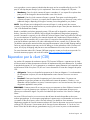
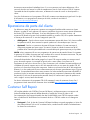
Customer Self Repair ............................................................................................................................... 68
Regulatory compliance notices ..................................................................................................... 76
Regulatory compliance identification numbers ............................................................................................. 76
Federal Communications Commission notice............................................................................................... 76
Modifications.......................................................................................................................................... 76
Cables ................................................................................................................................................... 77
Canadian notice ..................................................................................................................................... 77
European Union regulatory notice ............................................................................................................. 77
Disposal of waste equipment by users in private households in the European Union ......................................... 78
Japanese class A notice ........................................................................................................................... 78
BSMI notice ............................................................................................................................................ 78
Korean class A notice .............................................................................................................................. 78
Laser compliance .................................................................................................................................... 78
Battery replacement notice........................................................................................................................ 79
Taiwan battery recycling notice................................................................................................................. 79
Power cord statement for Japan................................................................................................................. 80
Acronyms and abbreviations........................................................................................................ 81
Index......................................................................................................................................... 83
Contents
4
Overview
In this section
Introduction ............................................................................................................................................. 5
Introduction
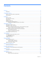
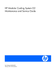
The HP Modular Cooling System is an air and water heat exchanger that removes high levels of excess
heat generated by equipment installed in HP 10642 G2 Racks. The installed equipment takes in cold air
through the front of the closed MCS unit, uses the air for internal cooling, and then expels it through the
rear vents after it has been warmed. The air is then recycled through the MCS unit.
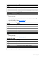
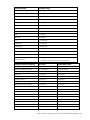
Item
Reference
1
Operator display
2
Heat exchanger units
Overview 5
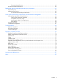
Item
Reference
3
Management module
4
Front door
5
AC transfer switch
6
Water group controller
7
Condensation pump assembly
8
Magnetic solenoid valve
9
Fan units
10
Rear door
11
Power connectors and RJ-45 connector
12
Leveling feet
Overview 6
Configuration factors
In this section
Optimum environment and site requirements ............................................................................................... 7
Site preparation ....................................................................................................................................... 7
Optimum environment and site requirements
CAUTION: Contaminated water may cause decreased cooling capacity or disruption in
service. It is important that the water flowing into the MCS unit meets the guidelines stated in
the HP Modular Cooling System Site Preparation Guide. Damage caused by contaminated
water is not covered by the MCS unit warranty.
IMPORTANT: You must read the HP Modular Cooling System Site Preparation Guide before
beginning the installation process.
Specific environmental requirements must be met to provide optimum performance with minimum
maintenance for your unit.
To help you learn about these requirements and to plan your unit configuration more efficiently, HP
provides the HP Modular Cooling System Site Preparation Guide.
Site preparation
The HP Modular Cooling System Site Preparation Guide provides specific information to help you plan
your unit configuration efficiently and organize your site location prior to delivery of your MCS unit.
To locate the latest version of the HP Modular Cooling System Site Preparation Guide:
1.
Go to the HP website (http://www.hp.com/go/rackandpower).
2.
Select Rack and Rack Options.
3.
Select Modular Cooling System.
4.
Select Support and Documents.
5.
Select Manuals.
6.
Select and download the HP Modular Cooling System Site Preparation Guide.
Configuration factors 7
Installation
In this section
MCS kit contents ...................................................................................................................................... 8
Rack hardware kit contents........................................................................................................................ 9
Required tools.......................................................................................................................................... 9
Installing the MCS unit ............................................................................................................................ 10
Powering up and configuring the unit ....................................................................................................... 16
MCS kit contents
•
HP MCS unit installed to an HP 10000 G2 Series Rack (1)
•
Automatic Door Release kit (1)
•
Counter hold wrench (1)
•
Water hose fitting wrench (1)
•
Rear plate cover (1)
•
Condensation pump to facility hose (blue) (1)
NOTE: This item might come directly attached to the MCS unit rather than in the standard kit
contents.
•
Condensation pan to facility hose (clear) (1)
•
Tubing clamp (2)
•
Adjustable clamp (1)
•
Power cord (3.6 m), L6-20 to C19 (2)
•
Power cord (3.6 m), IEC-309 to C19 (2)
•
CAT5e cable (25 ft) (1)
NOTE: This item might come directly attached to the MCS unit rather than in the standard kit
contents.
•
Serial cable (1)
Installation 8
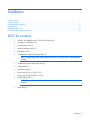
Rack hardware kit contents
1.
M6 screws (50)
2.
Cage nut insertion tool (1)
3.
M5.5 x 10 self tapping screws (6)
4.
M6 cage nuts (50)
5.
T-25 Torx bit (1)
6.
Cable management bracket (6)
7.
Rack ID plate (1)
8.
Leveling foot base (6)
9.
Documentation CD (1)
10.
Hook-and-loop cabling strap 12.7-cm (5 in) clip (1)
11.
Hook-and-loop cabling strap 20.3-cm (8 in) clip (1)
12.
Hook-and-loop cabling strap 30.5-cm (12 in) clip (1)
Required tools
The following tools are required for installation:
•
Flathead screwdriver
•
#2 Phillips screwdriver
•
Adjustable wrench
•
T-25 Torx driver
•
T-30 Torx driver
•
Water hose fitting wrench (included with your MCS kit contents)
Installation 9
•
Counter hold wrench (included with your MCS kit contents)
•
Bubble level
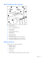
Installing the MCS unit
WARNING: The MCS unit and rack are shipped together on a heavy duty shock pallet
weighing approximately 2000 lb. HP recommends hiring professional movers to move the
heavy duty shock pallet, and then remove the MCS unit and rack from the pallet and into to the
final location.
CAUTION: Contaminated water may cause decreased cooling capacity or disruption in
service. It is important that the water flowing into the MCS unit meets the guidelines stated in
the HP Modular Cooling System Site Preparation Guide. Damage caused by contaminated
water is not covered by the MCS unit warranty.
IMPORTANT: You must read the HP Modular Cooling System Site Preparation Guide before
beginning the installation process.
IMPORTANT: Be sure to install the HP Water Hook-up Option Kit before connecting the In and
Out water hoses to the water lines.
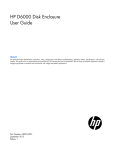
1.
Read the unpacking instructions on the MCS packaging material.
2.
With four or more people, carefully remove the MCS unit and rack from the pallet.
3.
Roll the MCS unit and rack approximately 91 cm (3 ft) in front of the final location.
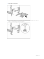
4.
Loosen the jam nut, and raise the unit by lowering the two rear leveling feet on both the MCS unit
and the rack until the rear caster plate can be removed.
Installation 10
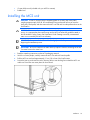
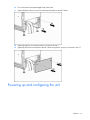
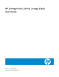
5.
Remove the rear caster plate.
6.
Lower the unit by raising the two rear leveling feet on both the MCS unit and the rack so that the
MCS unit can move freely on the remaining casters.
Installation 11
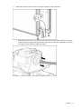
7.
Roll the MCS unit and rack into the final location while guiding the In and Out water hoses through
the raised floor opening.
8.
Using a bubble level, adjust the leveling feet to level the MCS unit and rack.
Installation 12
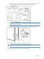
9.
Install and route the two drain hoses to the drain collection system catch basin.
a. Install the blue drain hose by inserting one end of the hose into the plastic collar quick connect
on the condensation pump, and then route the other end into either the condensation return line
or the gravity drain collection system catch basin.
Installation 13
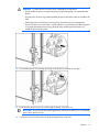
b. Install the clear drain hose by inserting one end of the hose into the condensation collection pan,
and then route the other end into the gravity drain collection system catch basin.
NOTE: Position the gravity drain collection system below the condensation collection pan,
allowing gravity to draw the water out of the condensation collection pan and into the gravity
drain collection system catch basin.
10.
Plug the network cable into the RJ-45 connector located above the In and Out water hoses.
11.
Guide the other end of the network cable through the bottom of the MCS unit.
IMPORTANT: Do not connect the power cords into a power supply.
12.
Plug the primary power cord into the power connector on the left.
Installation 14
WARNING: To reduce the risk of electric shock or damage to the equipment:
• Do not disable the power cord grounding plug. The grounding plug is an important safety
feature.
• Plug the power cord into a grounded (earthed) electrical outlet that is easily accessible at all
times.
• Unplug the power cord from the power supply to disconnect power to the equipment.
• Do not route the power cord where it can be walked on or pinched by items placed against
it. Pay particular attention to the plug, electrical outlet, and the point where the cord
extends from the storage system.
13.
If a secondary power cord is being used, plug it into the power connector on the right.
14.
Guide the other end of the power cords through the bottom of the MCS unit.
IMPORTANT: Be sure to flush the prearranged facility water lines of debris prior to connecting
them to the In and Out hoses.
15.
Connect the In and Out water hoses to the prearranged facility water lines.
Installation 15
16.
Turn on the water to the prearranged facility water lines.
17.
(Optional) Remove the two screws from the bottom brackets on the MCS frame.
18.
(Optional) Align the access panel with the two holes from step 17.
19.
(Optional) Secure the access panel to the MCS frame using the two screws you removed in step 17.
Powering up and configuring the unit
Installation 16
WARNING: To reduce the risk of electric shock or damage to the equipment:
• Do not disable the power cord grounding plug. The grounding plug is an important safety
feature.
• Plug the power cord into a grounded (earthed) electrical outlet that is easily accessible at all
times.
• Unplug the power cord from the power supply to disconnect power to the equipment.
• Do not route the power cord where it can be walked on or pinched by items placed against
it. Pay particular attention to the plug, electrical outlet, and the point where the cord
extends from the storage system.
The following steps outline the sequence for powering up and configuring the unit.
1.
Plug the power cord into an appropriate power source.
2.
Connect the network cable to your network infrastructure.
NOTE: If you have a DHCP server, you can change the IP address through the web interface
instead of through the serial port. For more information, refer to "Configuring the IP address
through the web interface."
3.
Connect a PC with a serial port or an asynchronous terminal to the serial communication port on the
management module (using the serial cable provided).
4.
Access the management module through a terminal emulation program, such as HyperTerminal
("Configuring HyperTerminal" on page 43) or Minicom.
5.
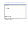
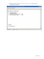
Log in to the HP Modular Cooling System Configuration Utility.
a. Enter the user name in the login field. The default user name is Admin.
Installation 17
b. Enter the password in the password field. The default password is Admin. The Main Menu screen
appears.
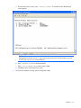
6.
Enter the product ID and serial number. The product ID and 10-digit serial number are located on a
label inside the rear MCS unit door.
Installation 18
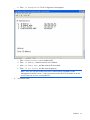
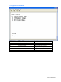
a. From the Main Menu screen, enter 3 Factory Default. The Default Product Identification
screen appears.
NOTE: MCS units with part number 405930-001 that have been upgraded from the
Management Controller version 1.0 may not have the product ID or serial number on the unit.
In such cases, use AF098A as the product ID.
b. Enter 2 Product ID MCS to set the product ID.
c.
Enter 3 Serial Number MCS to set the serial number.
d. Press Esc to return to the Main Menu screen.
7.
Access the HP Modular Cooling System Configuration Utility.
Installation 19
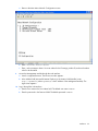
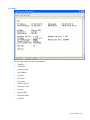
a. From the Main Menu screen, enter 1 Network Configuration. The Menu Network
Configuration screen appears.
Installation 20
b. Enter 1 IP Configuration. The IP Configuration screen appears.
c.
Enter 4 Enable/Disable DHCP to disable DHCP.
d. Enter 1 IP Address, and then enter the new IP address.
e. Enter 2 IP Subnet mask, and then enter the IP subnet mask.
f.
Enter 3 IP Def. Router, and then enter the gateway.
NOTE: MCS units with part number 405930-001 that have been upgraded from the
Management Controller version 1.0 may not have the product ID or serial number on the unit.
In such cases, use AF098A as the product ID.
8.
Activate the values.
Installation 21
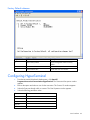
a. Return to the Main Menu Network Configuration screen.
b. Enter 4 Activate Actual Values.
c.
9.
Enter y at the prompt to reboot. You must reboot for the IP settings, product ID, and serial number
values to be activated.
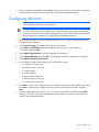
Access the Management module through the web interface.
a. Launch a supported browser. The browser window appears.
b. In the Address field (Microsoft® Internet Explorer) or the Location field (Mozilla), enter
http://ipaddress (where ipaddress is the IP address of the management module). The
login screen appears.
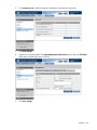
10.
Log in through the web interface.
a. Enter the user name in the User Name field. The default user name is Admin.
b. Enter the password in the Password field. The default password is Admin.
Installation 22
c.
11.
Click Sign In.
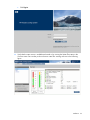
Verify that the water source is available and turned on by viewing the Water Flow status in the
Overview menu. Be sure that you do not have a water flow warning as shown in the following
figure.
Installation 23
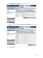
12.
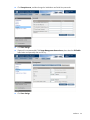
Click Setup>Accounts, and then change the Web Admin and Web User passwords.
13.
Click Save Settings.
14.
(Optional, but recommended) Click Setup>Management>Remote Access, then select the SSL Enable
radio button and optionally enter an SSL key.
15.
Click Save Settings.
Installation 24
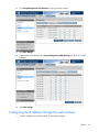
16.
Click Setup>Management>Trap Receivers to set up your trap receivers.
17.
Click Save Settings.
18.
(Optional but recommended) Click Setup>Management>SNMP Managers to set up your SNMP
managers.
19.
Click Save Settings.
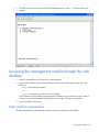
Configuring the IP address through the web interface
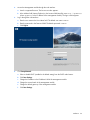
1.
View the IP address received from DHCP on the operator display.
Installation 25
2.
Access the Management module through the web interface.
a. Launch a supported browser. The browser window appears.
b. In the Address field (Internet Explorer) or the Location field (Mozilla), enter http://ipaddress
(where ipaddress is the IP address of the management module). The login screen appears.
3.
Log in through the web interface.
a. Enter the user name in the User Name field. The default user name is Admin.
b. Enter the password in the Password field. The default password is Admin.
c.
4.
Click Sign In.
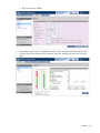
Click Setup>Network.
a. Select to disable DHCP (enabled is the default setting) from the DHCP radio buttons.
b. Click Save Settings.
c.
Change the IP address in the IP Address field of the management module.
d. Change the network mask of the management module.
e. Change the default gateway of the management module.
f.
Click Save Settings.
Installation 26
g. Log in to the new IP address.
5.
Verify that the water source is available and turned on by viewing the Water Flow status in the
Overview menu. Be sure that you do not have a water flow warning as shown in the following
figure.
Installation 27
6.
Click Setup>Accounts, and then change the Web Admin and Web User passwords.
7.
Click Save Settings.
8.
(Optional, but recommended) Click Setup>Management>Remote Access, then select the SSL Enable
radio button and optionally enter an SSL key.
9.
Click Save Settings.
Installation 28
10.
Click Setup>Management>Trap Receivers to set up your trap receivers.
11.
Click Save Settings.
12.
(Optional, but recommended) Click Setup>Management>SNMP Managers to set up your SNMP
managers.
13.
Click Save Settings.
Installation 29
Management module
In this section
Management module overview ................................................................................................................ 30
Management module components ............................................................................................................ 31
Accessing the management module through a terminal emulation program ................................................... 32
Accessing the management module through the web interface..................................................................... 33
Connecting an external alarm relay.......................................................................................................... 35
Management module overview
The HP Modular Cooling System has a management module which can be accessed remotely through the
web interface, that analyzes, queries, and manages various measurements, and warning and alarm
messages from the unit.
The management module analyzes measurements provided by each sensor or module, generates any
necessary warning or alarm messages, and then sends them to the web interface. When a new warning
or alarm occurs, the warning and alarm messages (on page 45) appear on the operator display, as well
as on the web interface Alarms menu and Alarm History menu. An alarm relay is also activated (if
installed on the unit and enabled in the appropriate web interface menu), and an alarm is signaled
acoustically by the internal beeper (if enabled in the appropriate web interface menu).
The management module performs regulation operations, such as:
•
Retrieving all measurements from the fan units and the water units in cycles, about once per second
(temperature, fan speed, and chilled water flow rate)
•
Analyzing all measurements and generated alarm and warning messages
•
Calculating heat removed from the water flow rate and temperature of the water supply and return
•
Measuring water flow rate
•
Regulating the server air inlet temperature by controlling the water flow
•
Sending control settings for fan speeds back to the HP Modular Cooling System
•
Sending various system values to the web interface
The web interface displays various measurements and warning and alarm messages (on page 45) from
the management module. Also, various system values can be set through the web interface and sent to the
management module. For more information about the web interface, see the HP Modular Cooling System
Web Interface User Guide.
The following values can be set through the web interface and sent to the management module:
•
Server Intake Temperature Set Point—Target value used by the management module for server intake
regulation
•
Hysteresis Value—Value used by the management module for air temperature regulation
•
High Temperature Threshold—Temperature difference above Server Intake Temperature Set Point for
temperature-critical alarm message
Management module 30
•
Warning Temperature Threshold—Temperature difference above Server Intake Temperature Set Point
for temperature warning message
•
Low Temperature Threshold—Temperature difference below Server Intake Temperature Set Point for
temperature warning message
The following values are displayed in the web interface for information only:
•
Fan Speed Target—Displays the percentage of the fan maximum speed
•
Water Valve—Displays the water valve state
•
Cooling Module 1 through 3—Displays the Server Intake and Server Exhaust Temperature and the
RPM of each cooling unit
•
Water Inlet Temperature—Displays the temperature of the water coming into the MCS unit to be
used to cool the servers
•
Water Outlet Temperature—Displays the temperature of the water after removing the server heat
•
Water Flow—Displays the value of the water flow in liters/gallons per minute
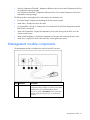
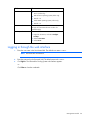
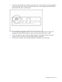
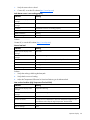
Management module components
The management module is located on the inside of the MCS front door.
Item Reference
Description
1
Used to confirm warnings, critical alarms, and
configuration setting changes, as well as to turn off the
audible alarm. Press and hold the C key for five
seconds, or click the Clear Alarms button on the Web
interface Setup tab>General menu, to confirm these
situations.
C key
Management module 31
Item Reference
Description
2
Used to indicate the internal status of the management
module, and to signal warnings and critical alarms.
3
4
Power/alarm LED
Traffic/link LED
Serial
communication
port
•
If the LED is green, there is power to the
management module and conditions are normal
•
If the LED is green and blinking, communication is
taking place
•
If the LED is yellow, a warning has been issued
•
If the LED is red, a critical alarm has been issued
•
If the LED is blinking green, yellow and red, a
configuration setting change has been made. Press
and hold the C key for five seconds to save the new
configuration settings to the internal memory of the
management module.
•
If the LED is off, there is no power to the
management module
Used to display the network connection.
•
If the LED is green, there is a 10-MB connection.
•
If the LED is yellow, there is a 100-MB connection.
•
If the LED is green or yellow and blinking, data is
being transferred.
•
If the LED is off, there is no connection.
Used to establish a serial connection (cable comes
attached).
For more information, refer to "Serial interface (on page
37)."
Accessing the management module through a
terminal emulation program
1.
Verify that a serial cable is connected between the management module and a host computer.
2.
Launch a terminal emulation program, such as HyperTerminal ("Configuring HyperTerminal" on
page 43) or Minicom.
For information about configuring the management module, see the HP Modular Cooling System
Web Interface User Guide.
3.
Log in through the terminal emulation program ("Logging in through the terminal emulation program"
on page 32).
Logging in through the terminal emulation program
1.
Enter the user name in the login field. The default user name is Admin.
Management module 32
2.
Enter the password in the password field. The default password is Admin. The Main Menu screen
appears.
Accessing the management module through the web
interface
1.
Launch a supported browser. The browser window appears.
2.
In the Address field (Microsoft® Internet Explorer) or the Location field (Mozilla), enter one of the
following:
http://hostname[:port number]
-orhttps://hostname[:port number] (if SSL is enabled)
where hostname is the IP address of the management module and port number is the port number if
using a port other than the default 80 for http and 443 for https. The login screen appears.
3.
Log in through the web browser.
Web interface requirements
The following table lists the minimum requirements necessary to operate the web interface.
Management module 33
Software
Browser
Web browser on a client
•
Microsoft® Internet Explorer 6.0 with Service
Pack 1 (32-bit only)
•
Red Hat Linux operating system (32-bit only)
•
Mozilla 1.4
•
SUSE LINUX operating system (32-bit only)
•
Mozilla 1.6
Monitor resolution
Minimum supported resolution of 1024 x 768, 16bit high color (maximize browser window for
optimal display)
Desktop resolution
SLES 9 Mozilla 1.6
1
Right-click the mouse, and select Configure
Desktop.
2
Select 1152 x 864.
3
Select 75 Hz.
Logging in through the web interface
1.
Enter the user name in the User Name field. The default user name is Admin.
NOTE: Passwords are case-sensitive.
2.
Enter the password in the Password field. The default password is Admin.
3.
Click Sign In. The HP Modular Cooling System web interface appears.
-orClick Clear to clear the credentials.
Management module 34
For instructions on changing the password, see the "Accounts menu" section in the HP Modular
Cooling System Web Interface User Guide.
Only one Admin session and one User session are supported at a time. Sessions can be terminated if a
second session is initiated (after successful login), or if a console session timeout occurs. In both situations,
the existing session is terminated and the login screen appears. Admin session logins, logouts, and
terminations are recorded in the Event Log menu. The console session timeout length can be enabled,
disabled, or modified in the Remote Access tab. The default is 30 minutes.
Connecting an external alarm relay
The external alarm relay must be ordered separately from the MCS unit, and can be purchased by visiting
the Rittal website (http://www.Rittal.com), and searching for the part number DK7320.590.
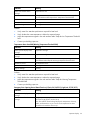
To add an external alarm relay:
Management module 35
1.
Connect the external alarm relay module to the sensor jack 1 (see figure below) on the management
module according to the instructions provided with the device. The management module LED status
light will blink red, yellow, and then green.
2.
Press and hold the management module C key for five seconds to confirm the new settings. The
management module LED status light turns green when the external alarm relay is ready.
3.
Test the external alarm relay by setting the High Temperature Threshold lower than the normal
settings from the web interface, and confirm that the alarm is generated.
4.
Once the test is complete, return the High Temperature Threshold to its normal setting.
Management module 36
Serial interface
In this section
HP Modular Cooling System Utility overview ............................................................................................. 37
Configuring HyperTerminal ..................................................................................................................... 43
Configuring Minicom.............................................................................................................................. 44
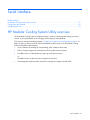
HP Modular Cooling System Utility overview
The HP Modular Cooling System Configuration Utility is used for entering network settings, accessing
controls, reviewing the details on the info page, and resetting to factory defaults.
First, log in to a terminal emulation program. ("Logging in through the terminal emulation program" on
page 32) After you have successfully initiated a terminal emulation session, the HP Modular Cooling
System Configuration Utility appears.
•
Open a submenu by entering the corresponding option number at the prompt.
•
Enter or change configuration information by following the onscreen prompts.
•
Press Esc or enter 0 at the submenu prompt to go to the previous menu.
-orPress Esc or enter 0 at the main menu prompt to exit the utility.
•
The management module must be reset before configuration changes can take effect.
Serial interface
37
Main menu
Option number
Submenu
Description
1
Network Configuration
Enter or change network properties for the
management module.
2
Info Page
View parameters for the management
module.
3
Factory Default
Change parameters back to default settings.
Serial interface
38
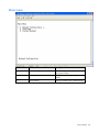
Menu Network Configuration submenu
Option number
Submenu
Description
1
IP Configuration
Enter or change the IP configuration for the
management module.
2
Change Passwords
Enter or change the passwords for the
management module.
3
HTTP/Console Timeout [min]
Enter or change the minimum HTTP/console
timeout for the management module.
4
Activate Actual Values
Select to accept changes and restart the unit.
Serial interface
39
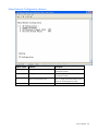
IP Configuration submenu
Option number
Submenu
Description
1
IP Address
Enter or change the IP address for the
management module.
2
IP Subnet mask
Enter or change the subnet mask for the
management module.
3
IP Def. Router
Enter or change the default router for the
management module.
4
Enable/Disable DHCP
Select to enable or disable DHCP.
Serial interface
40
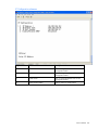
Change Passwords submenu
Option number
Submenu
Description
1
Console Password 'Admin'
Change the Admin password.
2
FTP Password 'ftpuser'
Change the FTP user password.
3
FTP Password 'ftpadmin'
Change the FTP Admin password.
4
HTTP Password 'User'
Change the HTTP user password.
5
HTTP Password 'Admin'
Change the HTTP Admin password.
Serial interface
41
Info page
The Info page displays the following parameters:
•
IP Address
•
Subnetmask
•
Router/Gateway
•
MAC Address
•
SysName
•
SysContact
•
SysLocation
•
Software Version
•
Hardware Version
•
Firmware
•
Serial Number
•
Manufacture Date
•
CMC-Info
Serial interface
42
Factory Default submenu
Option number
Submenu
Description
1
Set to Factory Default
Set the management module to factory
default.
2
Product ID MCS
Set the MCS unit product ID.
3
Serial Number MCS
Set the MCS unit serial number.
Configuring HyperTerminal
1.
From the Microsoft® Windows® desktop menu, click Start>All
Programs>Accessories>Communication>HyperTerminal. The Connection Description window
appears.
2.
Enter a description and select an icon for the connection. The Connect To window appears.
3.
Select the Com port through which to connect. The Com Properties window appears.
4.
Select the following parameter values.
Parameter
Value
Transmission rate
9600 Bps
Data bits
8
Parity
None
Stop bits
1
Flow control
None
Serial interface
43
5.
When a connection is established, press Enter and then log in. The Main menu for the management
module appears. Follow the onscreen options to configure the management module.
Configuring Minicom
NOTE: The following example uses Red Hat Linux 3.0. For more information, refer to your
Linux operating system Help or documentation.
IMPORTANT: Minicom is a utility that is loaded during the installation of Linux. However, if
you do not select the option to install the Linux Utilities during the operating system installation,
you cannot use Minicom without downloading the Minicom X.X.i386.rpm file from the Red Hat
website. (Refer to the procedure for installing RPMs on the Red Hat website.)
1.
Log in to a Linux console, or open a terminal and enter minicom-s at the command prompt. The
Configuration menu appears.
2.
Select Serial Port Setup. The Change which setting? menu appears.
3.
Select Option A (Serial Device). Manually change the device type from "dev/modem" to
"/dev/ttyS0" and press Enter.
4.
Select Option E (Bps/Par/Bits). The Comm Parameters menu appears.
5.
Select E (Speed 9600 Bps), and press Enter. The designation 9600 8 N1 appears next to Option E.
6.
Select Option F (Hardware Flow Control).
7.
Be sure that the Change which setting? menu is configured as follows:
o
A—Serial Device: /dev/ttyS0
o
B—Lockfile Location: /var/lock
o
C—Callin Program:
o
D—Callout Program:
o
E—Bps/Par/Bits: 9600 8 N1
o
F—Hardware Flow Control: No
o
G—Software Flow Control: No
8.
Press Enter to return to the Configuration menu. Scroll down to the Save setup as default option, and
press Enter. Scroll down the Configuration menu to the Exit from the Minicom option, and press
Enter.
9.
From the command prompt, enter Minicom. As soon as a connection is established, press Enter
and log in. The Main menu for the management module appears. Follow the onscreen options to
configure the management module.
Serial interface
44
Operator display
In this section
Operator display overview ...................................................................................................................... 45
Adjusting the operator display ................................................................................................................. 55
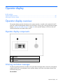
Operator display overview
The operator display provides information on the system operation, viewable on the outside of the MCS
front door. When the management module issues an alarm or warning, the warning and alarm messages
display ("Warning and alarm messages" on page 45) on the operator display, as well as on the web
interface Alarms menu and Alarm History menu.
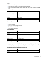
Operator display components
Item Reference
1
Operator display window
2
Scroll button
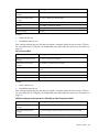
Warning and alarm messages
The following tables describe the possible warning and alarm messages that are sent to the management
module from the MCS unit and appear on the operator display, and on the web interface Alarms menu
and Alarm History menu.
Fan unit failed
Operator display
45
Indicators
Meaning
Actual operator display alarm
message
Top, Mid, or Bot Fan Mod. Failed
Actual web interface alarm
message
Top, Mid, or Bottom Fan Module Failed
Condition
Top, middle, or bottom fan module tach is less than its minimum rpm
Module
Top, middle, or bottom fan module
SNMP notification
Warning
Type of message
Warning
Solution:
1.
Remove the fan unit.
2.
Reinstall the same fan unit.
If the warning message does not clear after the module is reseated, replace the fan unit with a CSR part.
For more information on CSR parts, see "Replaceable parts and maintenance and service information (on
page 63)."
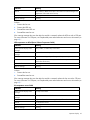
Fan unit not installed
Indicators
Meaning
Actual operator display alarm
message
Top, Mid, or Bot Fan Not installed
Actual web interface alarm
message
Top, Middle, or Bottom Fan Not installed
Condition
Failed connection to the fan unit sensors over the I²C bus (possible open
circuit)
Modules
Top, middle, or bottom fan module
SNMP notification
Warning
Type of message
Warning
Solution:
1.
Remove the fan unit.
2.
Reinstall the same fan unit.
If the warning message does not clear after the module is reseated, replace the fan unit with a CSR part.
For more information on CSR parts, see "Replaceable parts and maintenance and service information (on
page 63)."
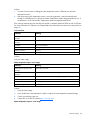
HEX (heat exchanger unit) temperature in failed (Server Intake Temperature failed)
Indicators
Meaning
Actual operator display alarm
message
HEX1, HEX2, or HEX3 Temp. In Failed
Actual web interface alarm
message
Top Heat Exchanger Intake Air Temperature Sensor to Server Failed
Condition
Temperature reading is beyond limit (possible open circuit)
Operator display
46
Indicators
Meaning
Sensors
HEX1, HEX2, or HEX3 sensors (this is the water to air heat exchanger unit
temperature of the intake to the servers)
SNMP notification
Warning
Type of message
Warning
Solution:
1.
Remove the fan unit.
2.
Remove the HEX unit.
3.
Reinstall the same HEX unit.
4.
Reinstall the same fan unit.
If the warning message does not clear after the module is reseated, replace the HEX unit with a CSR part.
For more information on CSR parts, see "Replaceable parts and maintenance and service information (on
page 63)."
HEX temperature out failed (Server Exhaust Temperature failed)
Indicators
Meaning
Actual operator display alarm
message
FAN1, FAN2, or FAN3 Temp. Out Failed
Actual web interface alarm
message
Top Fan Exhaust Air Temperature Sensor from Server Failed
Condition
Temperature reading is beyond limit (possible open circuit)
Sensors
FAN1, FAN2, or FAN3 sensors (this is the fan unit temperature of the
exhaust from the servers)
SNMP notification
Warning
Type of message
Warning
Solution:
1.
Remove the fan unit.
2.
Reinstall the same fan unit.
If the warning message does not clear after the module is reseated, replace the fan unit with a CSR part.
For more information on CSR parts, see "Replaceable parts and maintenance and service information (on
page 63)."
Air temperature sensor failed
Indicators
Meaning
Actual operator display alarm
message
Air Temp. Sens Failed
Actual web interface alarm
message
Air Temperature Sensor Failed
Condition
Single air temperature sensor is significantly different from the others
Sensors
Air temperature sensors
SNMP notification
Warning
Type of message
Warning
Operator display
47
Solution:
1.
View the Overview menu to distinguish which temperature sensor is different from the other
temperature sensors.
2.
After discovering which temperature sensor is not working properly, remove that module and
reinstall it. If the difference is in the Server Exhaust Temperature, replace the appropriate fan unit. If
the difference is in the Server Intake Temperature, replace the appropriate HEX unit.
If the warning message does not clear after the module is reseated, replace the HEX unit with a CSR part.
For more information on CSR parts, see "Replaceable parts and maintenance and service information (on
page 63)."
Low water flow
Indicators
Meaning
Actual operator display alarm
message
Water flow Low
Actual web interface alarm
message
Water flow Low
Condition
No or low water flow
Modules
Water group
SNMP notification
Warning
Type of message
Warning
Solution:
Verify the water supply.
Water temperature input is out of range
Indicators
Meaning
Actual operator display alarm
message
Water Temp. In Failed
Actual web interface alarm
message
Water Unit Temperature Input Out of Range
Condition
Water temperature sensor is not working properly (possible open circuit)
Sensors
Water group sensor
SNMP notification
Warning
Type of message
Warning
Solution:
1.
Verify the water supply.
2.
Verify whether the water temperature is below or above the water temperature expected range.
3.
Contact your building supervisor.
4.
Contact HP, or see the HP website (http://www.hp.com).
Water temperature output is out of range
Operator display
48
Indicators
Meaning
Actual operator display alarm
message
Water Temp. Out Failed
Actual web interface alarm
message
Water Unit Temperature Output Out of Range
Condition
Water temperature sensor is not working properly (possible open circuit)
Sensors
Water group sensor
SNMP notification
Warning
Type of message
Warning
Solution:
1.
Verify the water supply.
2.
Verify whether the water temperature is below or above the water temperature expected range.
3.
Contact your building supervisor.
4.
Contact HP, or see the HP website (http://www.hp.com).
Water flow sensor is not working properly
Indicators
Meaning
Actual operator display alarm
message
Water flow Sensor ?
Actual web interface alarm
message
Water flow Sensor Value Out of Range
Condition
Water flow sensor is not working properly
Sensor
Water group
SNMP notification
Warning
Type of message
Warning
Solution:
1.
Verify the water supply.
2.
Contact HP, or see the HP website (http://www.hp.com).
Water flow valve is closed
Indicators
Meaning
Actual operator display alarm
message
Water Valve ?
Actual web interface alarm
message
Water Valve Failed
Condition
Water flow valve is closed and water flow is detected
Modules
Water group
SNMP notification
Warning
Type of message
Warning
Solution:
Operator display
49
1.
Verify the water valve is closed.
2.
Contact HP, or see the HP website (http://www.hp.com).
Leak detector sensor is not working properly
Indicators
Meaning
Actual operator display alarm
message
Leak detector?
Actual web interface alarm
message
Leak detector Failed
Condition
Leak detector sensor is not working properly
Sensors
Leak detector sensor
SNMP notification
Warning
Type of message
Warning
Solution:
Contact HP, or see the HP website (http://www.hp.com).
Uneven heat load
Indicators
Meaning
Actual operator display alarm
message
Heat Load?
Actual web interface alarm
message
Heat Load Warning
Condition
Measured air temperature values dramatically different from top to bottom
Sensors
Air temperature sensors
SNMP notification
Warning
Type of message
Warning
Solution:
1.
Verify that nothing is blocking the heat path.
2.
Verify that the server is loading.
3.
Adjust the Temperature Difference for Heat Load Warning in the Advanced tab.
Heat overload condition (High Temperature Threshold field)
Indicators
Meaning
Actual operator display alarm
message
Temperature Warning
Actual web interface alarm
message
Temperature Warning
Condition
Heat overload condition
Modules or sensors
Average server air temperature is above the temperature assigned in the
web interface Intake Temp tab High Temperature Threshold field
SNMP notification
Critical
Type of message
Alarm
Operator display
50
Solution:
1.
Verify the water inlet temperature.
2.
Verify that the flow matches the specifications required for heat load.
3.
Adjust the temperature assigned in the web interface Intake Temp tab High Temperature Threshold
field.
Leakage detected
Indicators
Meaning
Actual operator display alarm
message
Leakage Detected
Actual web interface alarm
message
Leakage Detected
Condition
Leak is detected
Modules or sensors
Leakage detector actuated
SNMP notification
Critical
Type of message
Alarm
Solution:
1.
Open the rack doors.
2.
Power down the rack-mounted components.
3.
Turn off the water to the MCS unit.
4.
Locate the leak and correct it.
Communication failure
Indicators
Meaning
Actual operator display alarm
message
Comm. Failure I²C
Actual web interface alarm
message
Comm. Failure I²C
Condition
Management module cannot communicate with the MCS unit sensors
Modules or sensors
Any module or sensor
SNMP notification
Critical
Type of message
Alarm
Solution:
Power cycle the management module. If the alarm message continues to display, replace the management
module with a CSR part. For more information on CSR parts, see "Replaceable parts and maintenance
and service information (on page 63)."
Temperature below threshold (Low Temperature Threshold field)
Indicators
Meaning
Actual operator display alarm
message
Temperature Too low
Operator display
51
Indicators
Meaning
Actual web interface alarm
message
Temperature too low
Condition
Average server air temperature is lower than the temperature assigned in
the web interface Intake Temp tab Low Temperature Threshold field
Sensors
Air temperature sensor
SNMP notification
Warning
Type of message
Warning
Solution:
1.
Verify water flow matches specifications required for heat load.
2.
Verify whether the water temperature is below the expected range.
3.
Adjust the temperature assigned in the web interface Intake Temp tab Low Temperature Threshold
field.
4.
Contact your building supervisor.
Temperature above threshold (Warning Temperature Threshold field)
Indicators
Meaning
Actual operator display alarm
message
Temperature Too high
Actual web interface alarm
message
Temperature too high
Condition
Average server air temperature is above the temperature assigned in the
web interface Intake Temp tab Warning Temperature Threshold field
Modules or sensors
Air temperature sensor
SNMP notification
Warning
Type of message
Warning
Solution:
1.
Verify water flow matches specifications required for heat load.
2.
Verify whether the water temperature is above the expected range.
3.
Adjust the temperature assigned in the web interface Intake Temp tab Warning Temperature
Threshold field.
4.
Contact your building supervisor.
Emergency Door Opening due to Water Flow Loss (0 l/min; 36/34/35°C) (0 gal/min; 97/93/95°F)
Indicators
Meaning
Actual operator display alarm
message
Emergency Door, Flow
Actual web interface alarm
message
Emergency Door Opening due to Water Flow Loss (0 l/min;
36/34/35°C) (0 gal/min; 97/93/95°F)
Note: The interface alarm message displays the temperatures of the top,
middle, and bottom fans so you can see which temperature has been
exceeded and caused the alarm to trip.
Operator display
52
Indicators
Meaning
Condition
The Water Flow Loss Emergency Door Opening Temperature Threshold
has been exceeded or the water flow is less than 2 l/min (.5283
gal/min).
Modules or sensors
Server Intake Temperature, Water Flow Meter
SNMP notification
Critical
Type of message
Alarm
Solution:
1.
Verify water supply and verify the MCS unit is receiving water.
2.
Verify that the water flow is at least 2 l/min (.5283 gal/min) or greater.
3.
Verify that the Water Flow Loss Emergency Door Opening Temperature Threshold is not less than
5°C (9°F) above or more than 20°C (36°F) above the Server Intake Temperature Set Point.
4.
Adjust the temperature in the Server Intake Temperature Set Point or the Water Flow Loss Emergency
Door Opening Temperature Threshold fields to prevent false alarms.
IMPORTANT: Use caution when entering temperatures in the Emergency Door Opening fields.
Setting the temperature thresholds too low might cause the MCS unit to shut down.
Emergency Door Opening due to High Temperature (35/36/38°C) (95/97/100°F)
Indicators
Meaning
Actual operator display alarm
message
Emergency Door, Heat
Actual web interface alarm
message
Emergency Door Opening due to High Temperature (35/36/38°C)
(95/97/100°F)
Note: The interface alarm message displays the temperatures of the top,
middle, and bottom fans so you can see which temperature has been
exceeded and had caused the alarm to trip.
Condition
The High Temperature Emergency Door Opening Threshold has been
exceeded.
Modules or sensors
Server Intake Temperature
SNMP notification
Critical
Type of message
Alarm
Solution:
1.
Verify water supply and verify the MCS unit is receiving water.
2.
Verify that the High Temperature Emergency Door Opening Threshold is not less than 5°C (9°F)
above or more than 20°C (36°F) above the Server Intake Temperature Set Point, or that it is not
below the Water Flow Loss Emergency Door Opening Temperature Threshold.
3.
Adjust the temperature in the Server Intake Temperature Set Point or the Water Flow Loss Emergency
Door Opening Temperature Threshold fields to prevent false alarms.
IMPORTANT: Use caution when entering temperatures in the Emergency Door Opening fields.
Setting the temperature thresholds too low might cause the MCS unit to shut down.
The condensation pump has exceeded x cycles
Operator display
53
Indicators
Meaning
Actual operator display alarm
message
Excessive Moisture
Actual web interface alarm
message
The condensation pump has exceeded x cycles
Condition
The water level has exceeded the permissible level of the condensation
pump sensor
Modules or sensors
Condensation pump sensor
SNMP notification
Warning
Type of message
Warning
Solution:
1.
Look for leaks or determine if condensation is the cause.
2.
If no leaks are found, adjust the temperature in the Excessive Moisture: Condensation Pump Cycles
Warning Threshold field.
IMPORTANT: Use caution when entering temperatures in the Condensation Pump Threshold
fields. Be sure to determine the proper default settings to prevent false alarms, without masking
problems with the MCS.
Default settings will vary, depending on the humidity level of your data center and the heat
load generated by the equipment in the MCS.
The condensation pump has run more than x seconds
Indicators
Meaning
Actual operator display Excessive Moisture
alarm message
Actual web interface
alarm message
The condensation pump has run more than x seconds
Condition
The water level has exceeded the permissible level of the condensation pump sensor.
Modules or sensors
Condensation pump sensor
SNMP notification
Warning
Type of message
Warning
Solution:
1.
Look for leaks or determine if condensation is the cause.
2.
If no leaks are found, adjust the temperature in the Excessive Moisture: Condensation Pump Running
Time Warning Threshold field.
IMPORTANT: Use caution when entering temperatures in the Condensation Pump Threshold
fields. Be sure to determine the proper default settings to prevent false alarms, without masking
problems with the MCS.
Default settings will vary, depending on the humidity level of your data center and the heat
load generated by the equipment in the MCS.
Operator display
54
NOTE: A 24-hour clock starts when the condensation pump runs for the first time in more than
24 hours. A warning is issued if either the cycle threshold or pump running time is exceeded
within the 24-hour window. The clock stops and the counters are reset to zero for warning
purposes if the thresholds are not exceeded within 24 hours after the last time the
condensation pump runs.
NOTE: To clear the condensation pump cycles warning, click Cooling System in the left
navigation frame to access the Cooling System screen, and then click the Alarms/Warnings
tab. Under the Warnings section, set Alarm Reset to Manual and click Save Settings. Then,
return to the General menu and click Clear Alarms.
This step only clears the warning when the condensation pump is not running.
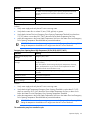
Adjusting the operator display
To optimize the operator display contrast:
1.
Using an 8-mm wrench, remove the three nuts securing the operator display rear cover to the back of
the MCS front door.
2.
Remove the operator display rear cover.
3.
Using a small flathead screwdriver, rotate the dial counter-clockwise to increase the contrast or
clockwise to decrease the contrast.
Operator display
55
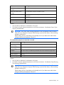
4.
Using an 8-mm wrench, reattach the three nuts removed in step 1 to replace the operator display
rear cover.
Operator display
56
Automatic Door Release Kit
In this section
Automatic Door Release Kit Overview....................................................................................................... 57
Automatic Door Release Kit Overview
The Automatic Door Release Kit is designed as a safety mechanism in the event that the MCS unit shuts off
unexpectedly. If the MCS unit shuts off unexpectedly, the electromagnetic locks on the front door, the rear
master door, and the rear slave door are immediately deactivated. This deactivation of the
electromagnetic locks will cause the release springs on each door to spring the rack doors open, and
allow air flow and cooling to the servers in the rack.
The Automatic Door Release Kit is included with your MCS unit. For specific installation instructions, see
the HP Modular Cooling System Automatic Door Release Kit Installation Instructions included with the kit.
Automatic Door Release Kit 57
Frequently asked questions
In this section
HP Modular Cooling System frequently asked questions.............................................................................. 58
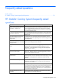
HP Modular Cooling System frequently asked
questions
Question
Answer
What cooling capacity ranges are
available in the MCS unit?
The cooling capacity of the heat exchanger units depends on the
water supply temperature and the server inlet set point. The MCS
unit is capable of cooling rack-mounted components consuming up
to 35 kW of electrical power.
Is special IT equipment required for
use with the MCS unit?
No, all IT equipment that uses the front-to-back cooling system (99%
of IT equipment) can be used without restriction in conjunction with
the MCS unit.
Does the additional heat from the
MCS unit increase the room
temperature?
In some cases, up to 10% of the total power supplied to the rack
may be lost to the room, depending on the server air setting and the
room temperature.
Yes, the control system automatically adjusts the water flow and air
Can the level of heat removal be
regulated in proportion to the waste flow to remove heat generated in the rack.
heat generated?
How is water connected to the MCS The water is connected to the unit using a 1 1/4 in flexible hose
unit?
and quick-disconnect automatic shutoff hose fittings. For more
information, see the HP Modular Cooling System Site Preparation
Guide on the HP website.
Can the MCS unit operate with the
front or rear door open?
Yes, due to the air curtain effect, the air will function normally with
little air lost. When the doors are open during operation, room air
mixes with air supplied to the servers.
Does the MCS unit require
maintenance?
No, assuming that the water quality is maintained, the MCS unit is
maintenance-free. For more information about water quality, see the
HP Modular Cooling System Site Preparation Guide on the HP
website.
Is a false floor necessary?
No, a false floor is not necessary to operate the MCS unit. For more
information, see the HP Modular Cooling System Site Preparation
Guide on the HP website.
Does condensation form?
During normal operation some condensation may form, but the MCS
unit condensation control system ensures that the condensation does
not reach any rack-mounted components or cause any damage. In
most cases, the condensation evaporates prior to reaching the MCS
unit condensation control system.
How does the MCS unit control
humidity?
There is some room-air interchange, so the moisture content of the
air inside the unit is the same as the room.
Frequently asked questions
58
Question
Answer
Does the air flow within the MCS
unit produce static electricity?
Very low humidity levels in the chilled air may produce static
electricity. However, static electricity is not a problem if the MCS
unit is operated at the specified settings located in the HP Site
Preparation Guide and the Environmental specifications listed in this
document.
Why do I get an extra line feed sent
from Windows when I access the
serial interface using an HP serial
console switch?
Enter these commands while logged in as Admin on the HP serial
console switch console port (where port x is the port connected to
the MCS management module):
port x set out lf=strip
port x set flow=Xonxof
Is water prevented from entering the Yes, the MCS unit is physically separate from the server enclosure.
MCS unit if a pipe breaks?
Therefore, there is no situation in which water can come directly in
contact with the servers. The base unit of each cooling module acts
as a condensation tray for water. These trays are connected
together, so that any water drains away at once through the
condensation drain. Also, each heat exchanger module has a leak
and condensation tray that transfers water to the bottom of the MCS
unit where it flows to the building condensation return system. If a
leak occurs, the integrated leak sensor detects it and an alarm
would is issued so that action can be quickly taken.
What will happen if water stops
flowing to the MCS unit?
If you have the Automatic Door Release Kit, an alarm will trigger the
doors of the rack to open, allowing the servers to be cooled by the
room ambient.
Can I install an MCS unit to an
existing rack in my data center?
No, the MCS unit ships with an empty HP 10000 G2 rack.
However, Configure to Order (CTO) is available.
Frequently asked questions
59
Troubleshooting
In this section
HP Modular Cooling System troubleshooting ............................................................................................. 60
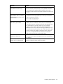
HP Modular Cooling System troubleshooting
Issue
Resolution
The water flow is low or not
flowing.
For more information, see the "Temperature Control settings" section
in the HP Modular Cooling System Web Interface User Guide
located on the Documentation CD included with this product.
The fan speed is too low.
For more information, see the "Cooling performance parameters"
section in the HP Modular Cooling System Web Interface User
Guide located on the Documentation CD included with this product.
The fan speed is too high.
For more information, see the "Cooling performance parameters"
section in the HP Modular Cooling System Web Interface User
Guide located on the Documentation CD included with this product.
The average server intake
temperature (air going to the
servers) is too high.
For more information, see the "Cooling performance parameters"
section in the HP Modular Cooling System Web Interface User
Guide located on the Documentation CD included with this product.
The average server intake
temperature (air going to the
servers) is too low.
For more information, see the "Cooling performance parameters"
section in the HP Modular Cooling System Web Interface User
Guide located on the Documentation CD included with this product.
The average exhaust temperature
For more information, see the "Cooling performance parameters"
(air coming out of the servers) is too section in the HP Modular Cooling System Web Interface User
high.
Guide located on the Documentation CD included with this product.
The average exhaust temperature
For more information, see the "Cooling performance parameters"
(air coming out of the servers) is too section in the HP Modular Cooling System Web Interface User
low.
Guide located on the Documentation CD included with this product.
Press and hold the management module C key for five seconds to
The settings that have been
modified through the web interface confirm these settings.
are not accepted, and the
management module LED is blinking
red, yellow, or green.
Press and hold the management module C key for five seconds to
The measurement readings on the
confirm these settings.
management module display or
web interface seem to be incorrect,
and the management module LED is
blinking red, yellow, or green.
The heat exchanger unit stops
operating correctly.
Remove the corresponding fan unit to keep the Automatic Door
Release Kit from holding the rack doors open.
Troubleshooting 60
Specifications
In this section
MCS specifications................................................................................................................................. 61
HP 10642 G2 Rack specifications ........................................................................................................... 62
MCS specifications
Item
Specification
Voltage
208–240 VAC +/- 10%, 50–60 Hz
Maximum Height
(including the rack)
200 cm (78.7 in)
Maximum Width
(including the rack)
90.9 cm (35.8 in) maximum
Maximum Depth
(including the rack and
rack handle)
127 cm (50 in)
Maximum Shipping
Height (on skid)
224.8 cm (88.5 in)
Maximum Shipping
Width (on skid)
122 cm (48 in)
Maximum Shipping
Depth (on skid)
177.8 cm (70 in)
Maximum Depth with
Rear Extension Kit
installed
142.5 cm (56.1 in)
Net Weight (including
the empty rack)
540 kg (1190 lb)
Shipping Weight (gross 621.4 kg (1370 lb)
with packaging)
Effective cooling with
75 l/min (20 gal/min)
water supply at 7°C,
cold air at 25°C
35 kW
Rated current maximum 208 VAC–15 Amps
Cooling medium
water
Minimum
recommended water
inlet temperature
7ºC (45ºF)
Permissible operating
pressure pmax
100 psi
Specifications
61
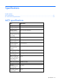
Thermal and air flow performance
Maximum thermal and air flow performance
parameters
Specifications
Air temperature—inlet to rack-mounted components
25ºC (68ºF)
Chilled water temperature
7º–10°C (45º–50°F)
Total rack-mounted component air flow
2,600 cfm or less at 0 or more pressure drop
across the rack-mounted components
Chilled water flow rate
21 gal/min
Chilled water pressure differential at flow needed to
meet thermal specifications
2.0 bar delta pressure
Heat lost to room
approximately 10% maximum depending on
the MCS settings and room temperature
Heat transferred to cooling fluid
35 kW maximum
Environmental specifications
Features
Specifications
Operating temperature
5ºC to 52ºC (41ºF to 95ºF)
Non-operating temperature
0ºC to 60ºC (32ºF to 140ºF)
Transit temperature
-30ºC to 60ºC (-22ºF to 140ºF), up to 72 hours
Storage temperature
-20ºC to 60ºC (-4ºF to 140ºF)
Operating humidity
20 to 80% relative humidity (non-condensing)
Non-operating humidity
5 to 95% relative humidity (non-condensing)
Operating altitude
-76.2 to 3,048 m (-250 to 10,000 ft)
Non-operating altitude
-76.2 to 9,144 m (-250 to 30,000 ft)
HP 10642 G2 Rack specifications
U height Width
Depth
42U
1,000 mm 907.18 kg (2,000 lb)
(39.37 in)
600 mm
(23.82 in)
Dynamic load (gross)
Static load
907.18 kg (2,000
lb)
Specifications
62
Replaceable parts and maintenance and service
information
In this section
Replaceable parts .................................................................................................................................. 63
Maintenance and service ........................................................................................................................ 63
Replaceable parts
The heat exchanger units and fan units are replaceable during real-time operation. Other unit parts are
also replaceable. For more information on replaceable parts and CSR parts, refer to Technical support (on
page 68).
Maintenance and service
For information on maintenance and service, refer to the HP website (http://www.hp.com).
Air and water heat exchanger maintenance
The air and water heat exchanger requires no maintenance. If particulates are present in the cooling
water, a filter must be fitted immediately upstream from the water inlet fittings. Check the functionality of
the condensation drainage system regularly. Regularly perform visual inspections for leaks (annually).
Replaceable parts and maintenance and service information
63
Water quality and leveling requirements, and
condensation management
In this section
Water quality requirements and specifications........................................................................................... 64
Leveling requirements ............................................................................................................................. 66
Condensation management ..................................................................................................................... 67
Water quality requirements and specifications
Tap water might be sufficient for some closed-loop systems. Water quality in a closed-loop system
encounters problems with scaling, blockage, leaks, and corrosion that are typically found in tap water
containing many chemicals and minerals. Determining the acceptable water quality range is the most
essential element of the system requirements. For more information, see the HP Modular Cooling System
Site Preparation Guide on the HP website (http://www.hp.com).
Cooling water composition guidelines
•
The closed-loop water must not contain any lime scale deposits or loose debris.
•
The water should have a low level of hardness, particularly a low level of carbon hardness.
However, the water should not be so soft that it attacks the materials with which it comes into
contact.
•
A 1-micron filter should be used to remove free floating particulates and regularly maintained.
•
Salt content should be monitored because it rises over time as a result of evaporation in the systems,
causing the water to become more corrosive. (Electrical conductivity increases as the concentration
of dissolved substances rises.)
•
Periodically some of the enriched water should be removed and new fresh water should be added to
avoid the formation of Gypsiferous water, which is unsuitable for cooling purposes. Gypsiferous
water has a tendency to form boiler scale, which is particularly difficult to remove.
•
Cooling water should be free from iron and manganese because these minerals tend to settle in the
pipes and cause blockage.
•
The presence of organic impurities with algaecides and other inhibitors should be minimized to
reduce the creation of sludge deposits and microbiological contamination.
Acceptable water quality range
The following are water quality ranges required for continuous quality of performance for the MCS unit:
Hydrological data
Acceptable range
pH value
7–8.5
Carbonic acid
> 3 < 8 ºdH
Water quality and leveling requirements, and condensation management 64
Hydrological data
Acceptable range
Free carbonic acid
8–15 mg/dm3
Accompanying carbonic acid
8–15 mg/dm3
Corrosive carbonic acid
0 mg/dm3
Sulphides
Free
Oxygen
< 10 mg/dm3
Chloride ions
< 50 mg/dm3
Sulphate ions
< 250 mg/dm3
Nitrates and nitrites
< 10 mg/dm3
CSB
< 7 mg/dm3
Ammonia
< 5 mg/dm3
Iron
< 0, 2 mg/dm3
Manganese
< 0, 2 mg/dm3
Conductivity
< 2200 µS/cm
Residue on evaporation
< 500 mg/dm3
Potassium permanganate consumption
< 25 mg/dm3
Suspended matter
< 3 mg/dm3
Particular size range filtration
recommendations
> 3 < 15 mg/dm3 part flow purification recommended
Closed-loop water specifications
Raw water
Treated water system
pH
6.5–9.5
8.0–10.0
Specific conductance at 25°C
10–1,000 µmhos
10–4,500 µmhos
"M" Alkalinity (CaCO3)
20–300 ppm
100–1,000 ppm
Sulfur (SO4)
0–150 ppm
0–150 ppm
Chloride (Cl)
0–150 ppm
0–150 ppm
Hardness (CaCO3)
0–350 ppm
0–350 ppm
Calcium hardness (CaCO3)
0–200 ppm
0–200 ppm
Magnesium hardness (CaCO3)
0–150 ppm
0–150 ppm
Copper (Cu)
< 0.10 ppm
< 0.20 ppm
Iron (Fe)
< 3.0 ppm
< 3.0 ppm
Aluminum (Al)
0.5 ppm maximum
0.5 ppm maximum
Sodium (Na)
0–1,000 ppm
0–1,000 ppm
Silica (SiO2)
0–150 ppm
0–150 ppm
Zinc (Zn)
1.0 ppm maximum
1.0 ppm maximum
Manganese (Mn)
0.1 ppm maximum
0.1 ppm maximum
Phosphate Ortho- (PO4)
3 ppm
3 ppm
Nitrite (NO2)
700–1,200 ppm
700–1,200 ppm
> 15 mg/dm3 continuous purification recommended
Water quality and leveling requirements, and condensation management 65
Closed-loop water specifications
Raw water
Treated water system
Molybdenum (Mo)
50–300 ppm
50–300 ppm
Tolytriazole
15–20 ppm
15–20 ppm
Suspended solid
< 1 µm
< 1 µm
Monitoring the quality of cooling solutions
Depending on the type of installation, it is advisable to put in place certain processes and procedures for
monitoring the quality of the cooling solution and for performing preventative maintenance. The following
table lists common types of contamination and techniques to eliminate them:
Type of impurity
Procedure
Mechanical
contamination
Filter the water using 1-micron filter (3.9e-5 in), sieving
filter, sand filter, cartridge filter, or pre-coated filter.
Hardness too high
Soften the water through ion exchange.
Moderate content of
mechanical impurities
and hardness agents
Add stabilizers, dispersing agents, or both to the water.
Moderate content of
chemical impurities
Use Anodic inhibitors: Nitrite based treatment
Use Azole treatment for copper corrosion.
Use Cathodic inhibitors: Molybdate based treatment
Inoculate the water with passivators, inhibitors, or both.
Biological impurities,
microbacteria, and
algae
Inoculate the water with biocides.
To ensure ongoing safe reliable operation of the closed-loop cooling system, see "Acceptable water
quality range (on page 64)."
Frost damage
To avoid frost damage, the water temperature must not be allowed to fall below the minimum permissible
temperature of +4 ºC (+39.2 ºF) at any point in the water cycle.
Before storage or transportation at sub-zero temperatures, the water cycle must be drained completely
using compressed air. Avoid setting the target temperature lower than is necessary because the danger of
falling below the dew point increases as water temperature decreases (condensation buildup). Ensure that
the enclosure is sealed on all sides, and in particular at the cable inlet (condensation formation).
Leveling requirements
Adjust the MCS leveling feet so that the unit is level.
For more information about seismic area considerations, refer to the HP Modular Cooling System Site
Preparation Guide on the HP website (http://www.hp.com).
Water quality and leveling requirements, and condensation management 66
Condensation management
Any condensation that forms is collected in each individual cooling module and is taken through a
discharge tube to a condensation tray integrated in the base assembly. Where multiple cooling modules
are used, the condensate discharge tubes are connected to one another using quick connectors. Any
condensation that occurs is then removed through this series of connections to the condensation tray.
When the specified condensation level in the condensation tray is reached, a sensor activates a pump
that pumps the condensation into the return system. A further discharge tube runs out of the system from
condensation tray to drain excess fluid if needed. This hose should be connected to a collection system or
an external drain.
To ensure reliable drainage:
•
Ensure no kinks form in the drainage hose.
•
Do not reduce diameter of drainage hose.
•
Route the drainage hoses so that they always run downhill.
To avoid excessive buildup of condensate and to conserve energy, consider raising the cooling water
temperature to the necessary cooling capacity.
Water quality and leveling requirements, and condensation management 67
Technical support
In this section
Before you contact HP............................................................................................................................. 68
HP contact information............................................................................................................................ 68
Customer Self Repair .............................................................................................................................. 68
Before you contact HP
Be sure to have the following information available before you call HP:
•
Technical support registration number (if applicable)
•
Product serial number
•
Product model name and number
•
Applicable error messages
•
Add-on boards or hardware
•
Third-party hardware or software
•
Operating system type and revision level
HP contact information
For the name of the nearest HP authorized reseller:
•
In the United States, see the HP US service locator webpage (http://www.hp.com/service_locator).
•
In other locations, see the Contact HP worldwide (in English) webpage
(http://welcome.hp.com/country/us/en/wwcontact.html).
For HP technical support:
•
•
In the United States, for contact options see the Contact HP United States webpage
(http://welcome.hp.com/country/us/en/contact_us.html). To contact HP by phone:
o
Call 1-800-HP-INVENT (1-800-474-6836). This service is available 24 hours a day, 7 days a
week. For continuous quality improvement, calls may be recorded or monitored.
o
If you have purchased a Care Pack (service upgrade), call 1-800-633-3600. For more
information about Care Packs, refer to the HP website (http://www.hp.com).
In other locations, see the Contact HP worldwide (in English) webpage
(http://welcome.hp.com/country/us/en/wwcontact.html).
Customer Self Repair
HP products are designed with many Customer Self Repair (CSR) parts to minimize repair time and allow
for greater flexibility in performing defective parts replacement. If during the diagnosis period HP (or HP
Technical support 68
service providers or service partners) identifies that the repair can be accomplished by the use of a CSR
part, HP will ship that part directly to you for replacement. There are two categories of CSR parts:
•
Mandatory—Parts for which customer self repair is mandatory. If you request HP to replace these
parts, you will be charged for the travel and labor costs of this service.
•
Optional—Parts for which customer self repair is optional. These parts are also designed for
customer self repair. If, however, you require that HP replace them for you, there may or may not be
additional charges, depending on the type of warranty service designated for your product.
NOTE: Some HP parts are not designed for customer self repair. In order to satisfy the customer
warranty, HP requires that an authorized service provider replace the part. These parts are identified as
"No" in the Illustrated Parts Catalog.
Based on availability and where geography permits, CSR parts will be shipped for next business day
delivery. Same day or four-hour delivery may be offered at an additional charge where geography
permits. If assistance is required, you can call the HP Technical Support Center and a technician will help
you over the telephone. HP specifies in the materials shipped with a replacement CSR part whether a
defective part must be returned to HP. In cases where it is required to return the defective part to HP, you
must ship the defective part back to HP within a defined period of time, normally five (5) business days.
The defective part must be returned with the associated documentation in the provided shipping material.
Failure to return the defective part may result in HP billing you for the replacement. With a customer self
repair, HP will pay all shipping and part return costs and determine the courier/carrier to be used.
For more information about HP's Customer Self Repair program, contact your local service provider. For
the North American program, refer to the HP website (http://www.hp.com/go/selfrepair).
Réparation par le client (CSR)
Les produits HP comportent de nombreuses pièces CSR (Customer Self Repair = réparation par le client)
afin de minimiser les délais de réparation et faciliter le remplacement des pièces défectueuses. Si pendant
la période de diagnostic, HP (ou ses partenaires ou mainteneurs agréés) détermine que la réparation peut
être effectuée à l'aide d'une pièce CSR, HP vous l'envoie directement. Il existe deux catégories de pièces
CSR:
•
Obligatoire - Pièces pour lesquelles la réparation par le client est obligatoire. Si vous demandez à
HP de remplacer ces pièces, les coûts de déplacement et main d'œuvre du service vous seront
facturés.
•
Facultatif - Pièces pour lesquelles la réparation par le client est facultative. Ces pièces sont
également conçues pour permettre au client d'effectuer lui-même la réparation. Toutefois, si vous
demandez à HP de remplacer ces pièces, l'intervention peut ou non vous être facturée, selon le type
de garantie applicable à votre produit.
REMARQUE: Certaines pièces HP ne sont pas conçues pour permettre au client d'effectuer lui-même la
réparation. Pour que la garantie puisse s'appliquer, HP exige que le remplacement de la pièce soit
effectué par un Mainteneur Agréé. Ces pièces sont identifiées par la mention "Non" dans le Catalogue
illustré.
Les pièces CSR sont livrées le jour ouvré suivant, dans la limite des stocks disponibles et selon votre
situation géographique. Si votre situation géographique le permet et que vous demandez une livraison le
jour même ou dans les 4 heures, celle-ci vous sera facturée. Pour bénéficier d'une assistance
téléphonique, appelez le Centre d'assistance technique HP. Dans les documents envoyés avec la pièce de
rechange CSR, HP précise s'il est nécessaire de lui retourner la pièce défectueuse. Si c'est le cas, vous
devez le faire dans le délai indiqué, généralement cinq (5) jours ouvrés. La pièce et sa documentation
Technical support 69
doivent être retournées dans l'emballage fourni. Si vous ne retournez pas la pièce défectueuse, HP se
réserve le droit de vous facturer les coûts de remplacement. Dans le cas d'une pièce CSR, HP supporte
l'ensemble des frais d'expédition et de retour, et détermine la société de courses ou le transporteur à
utiliser.
Pour plus d'informations sur le programme CSR de HP, contactez votre Mainteneur Agrée local. Pour plus
d'informations sur ce programme en Amérique du Nord, consultez le site Web HP
(http://www.hp.com/go/selfrepair).
Riparazione da parte del cliente
Per abbreviare i tempi di riparazione e garantire una maggiore flessibilità nella sostituzione di parti
difettose, i prodotti HP sono realizzati con numerosi componenti che possono essere riparati direttamente
dal cliente (CSR, Customer Self Repair). Se in fase di diagnostica HP (o un centro di servizi o di
assistenza HP) identifica il guasto come riparabile mediante un ricambio CSR, HP lo spedirà direttamente
al cliente per la sostituzione. Vi sono due categorie di parti CSR:
•
Obbligatorie – Parti che devono essere necessariamente riparate dal cliente. Se il cliente ne affida
la riparazione ad HP, deve sostenere le spese di spedizione e di manodopera per il servizio.
•
Opzionali – Parti la cui riparazione da parte del cliente è facoltativa. Si tratta comunque di
componenti progettati per questo scopo. Se tuttavia il cliente ne richiede la sostituzione ad HP,
potrebbe dover sostenere spese addizionali a seconda del tipo di garanzia previsto per il prodotto.
NOTA: alcuni componenti HP non sono progettati per la riparazione da parte del cliente. Per rispettare
la garanzia, HP richiede che queste parti siano sostituite da un centro di assistenza autorizzato. Tali parti
sono identificate da un "No" nel Catalogo illustrato dei componenti.
In base alla disponibilità e alla località geografica, le parti CSR vengono spedite con consegna entro il
giorno lavorativo seguente. La consegna nel giorno stesso o entro quattro ore è offerta con un
supplemento di costo solo in alcune zone. In caso di necessità si può richiedere l'assistenza telefonica di
un addetto del centro di supporto tecnico HP. Nel materiale fornito con una parte di ricambio CSR, HP
specifica se il cliente deve restituire dei componenti. Qualora sia richiesta la resa ad HP del componente
difettoso, lo si deve spedire ad HP entro un determinato periodo di tempo, generalmente cinque (5) giorni
lavorativi. Il componente difettoso deve essere restituito con la documentazione associata nell'imballo di
spedizione fornito. La mancata restituzione del componente può comportare la fatturazione del ricambio
da parte di HP. Nel caso di riparazione da parte del cliente, HP sostiene tutte le spese di spedizione e
resa e sceglie il corriere/vettore da utilizzare.
Per ulteriori informazioni sul programma CSR di HP contattare il centro di assistenza di zona. Per il
programma in Nord America fare riferimento al sito Web HP (http://www.hp.com/go/selfrepair).
Customer Self Repair
HP Produkte enthalten viele CSR-Teile (Customer Self Repair), um Reparaturzeiten zu minimieren und
höhere Flexibilität beim Austausch defekter Bauteile zu ermöglichen. Wenn HP (oder ein HP
Servicepartner) bei der Diagnose feststellt, dass das Produkt mithilfe eines CSR-Teils repariert werden
kann, sendet Ihnen HP dieses Bauteil zum Austausch direkt zu. CSR-Teile werden in zwei Kategorien
unterteilt:
•
Zwingend – Teile, für die das Customer Self Repair-Verfahren zwingend vorgegeben ist. Wenn Sie
den Austausch dieser Teile von HP vornehmen lassen, werden Ihnen die Anfahrt- und Arbeitskosten
für diesen Service berechnet.
Technical support 70
•
Optional – Teile, für die das Customer Self Repair-Verfahren optional ist. Diese Teile sind auch für
Customer Self Repair ausgelegt. Wenn Sie jedoch den Austausch dieser Teile von HP vornehmen
lassen möchten, können bei diesem Service je nach den für Ihr Produkt vorgesehenen
Garantiebedingungen zusätzliche Kosten anfallen.
HINWEIS: Einige Teile sind nicht für Customer Self Repair ausgelegt. Um den Garantieanspruch des
Kunden zu erfüllen, muss das Teil von einem HP Servicepartner ersetzt werden. Im illustrierten Teilekatalog
sind diese Teile mit „No“ bzw. „Nein“ gekennzeichnet.
CSR-Teile werden abhängig von der Verfügbarkeit und vom Lieferziel am folgenden Geschäftstag
geliefert. Für bestimmte Standorte ist eine Lieferung am selben Tag oder innerhalb von vier Stunden gegen
einen Aufpreis verfügbar. Wenn Sie Hilfe benötigen, können Sie das HP technische Support Center
anrufen und sich von einem Mitarbeiter per Telefon helfen lassen. Den Materialien, die mit einem CSRErsatzteil geliefert werden, können Sie entnehmen, ob das defekte Teil an HP zurückgeschickt werden
muss. Wenn es erforderlich ist, das defekte Teil an HP zurückzuschicken, müssen Sie dies innerhalb eines
vorgegebenen Zeitraums tun, in der Regel innerhalb von fünf (5) Geschäftstagen. Das defekte Teil muss
mit der zugehörigen Dokumentation in der Verpackung zurückgeschickt werden, die im Lieferumfang
enthalten ist. Wenn Sie das defekte Teil nicht zurückschicken, kann HP Ihnen das Ersatzteil in Rechnung
stellen. Im Falle von Customer Self Repair kommt HP für alle Kosten für die Lieferung und Rücksendung auf
und bestimmt den Kurier-/Frachtdienst.
Weitere Informationen über das HP Customer Self Repair Programm erhalten Sie von Ihrem Servicepartner
vor Ort. Informationen über das CSR-Programm in Nordamerika finden Sie auf der HP Website unter
(http://www.hp.com/go/selfrepair).
Reparaciones del propio cliente
Los productos de HP incluyen muchos componentes que el propio usuario puede reemplazar (Customer
Self Repair, CSR) para minimizar el tiempo de reparación y ofrecer una mayor flexibilidad a la hora de
realizar sustituciones de componentes defectuosos. Si, durante la fase de diagnóstico, HP (o los
proveedores o socios de servicio de HP) identifica que una reparación puede llevarse a cabo mediante el
uso de un componente CSR, HP le enviará dicho componente directamente para que realice su
sustitución. Los componentes CSR se clasifican en dos categorías:
•
Obligatorio: componentes para los que la reparación por parte del usuario es obligatoria. Si
solicita a HP que realice la sustitución de estos componentes, tendrá que hacerse cargo de los
gastos de desplazamiento y de mano de obra de dicho servicio.
•
Opcional: componentes para los que la reparación por parte del usuario es opcional. Estos
componentes también están diseñados para que puedan ser reparados por el usuario. Sin embargo,
si precisa que HP realice su sustitución, puede o no conllevar costes adicionales, dependiendo del
tipo de servicio de garantía correspondiente al producto.
NOTA: Algunos componentes no están diseñados para que puedan ser reparados por el usuario. Para
que el usuario haga valer su garantía, HP pone como condición que un proveedor de servicios
autorizado realice la sustitución de estos componentes. Dichos componentes se identifican con la palabra
"No" en el catálogo ilustrado de componentes.
Según la disponibilidad y la situación geográfica, los componentes CSR se enviarán para que lleguen a
su destino al siguiente día laborable. Si la situación geográfica lo permite, se puede solicitar la entrega
en el mismo día o en cuatro horas con un coste adicional. Si precisa asistencia técnica, puede llamar al
Centro de asistencia técnica de HP y recibirá ayuda telefónica por parte de un técnico. Con el envío de
materiales para la sustitución de componentes CSR, HP especificará si los componentes defectuosos
deberán devolverse a HP. En aquellos casos en los que sea necesario devolver algún componente a HP,
Technical support 71
deberá hacerlo en el periodo de tiempo especificado, normalmente cinco días laborables. Los
componentes defectuosos deberán devolverse con toda la documentación relacionada y con el embalaje
de envío. Si no enviara el componente defectuoso requerido, HP podrá cobrarle por el de sustitución. En
el caso de todas sustituciones que lleve a cabo el cliente, HP se hará cargo de todos los gastos de envío
y devolución de componentes y escogerá la empresa de transporte que se utilice para dicho servicio.
Para obtener más información acerca del programa de Reparaciones del propio cliente de HP, póngase
en contacto con su proveedor de servicios local. Si está interesado en el programa para Norteamérica,
visite la página web de HP siguiente (http://www.hp.com/go/selfrepair).
Customer Self Repair
Veel onderdelen in HP producten zijn door de klant zelf te repareren, waardoor de reparatieduur tot een
minimum beperkt kan blijven en de flexibiliteit in het vervangen van defecte onderdelen groter is. Deze
onderdelen worden CSR-onderdelen (Customer Self Repair) genoemd. Als HP (of een HP Service Partner)
bij de diagnose vaststelt dat de reparatie kan worden uitgevoerd met een CSR-onderdeel, verzendt HP
dat onderdeel rechtstreeks naar u, zodat u het defecte onderdeel daarmee kunt vervangen. Er zijn twee
categorieën CSR-onderdelen:
•
Verplicht: Onderdelen waarvoor reparatie door de klant verplicht is. Als u HP verzoekt deze
onderdelen voor u te vervangen, worden u voor deze service reiskosten en arbeidsloon in rekening
gebracht.
•
Optioneel: Onderdelen waarvoor reparatie door de klant optioneel is. Ook deze onderdelen zijn
ontworpen voor reparatie door de klant. Als u echter HP verzoekt deze onderdelen voor u te
vervangen, kunnen daarvoor extra kosten in rekening worden gebracht, afhankelijk van het type
garantieservice voor het product.
OPMERKING: Sommige HP onderdelen zijn niet ontwikkeld voor reparatie door de klant. In verband
met de garantievoorwaarden moet het onderdeel door een geautoriseerde Service Partner worden
vervangen. Deze onderdelen worden in de geïllustreerde onderdelencatalogus aangemerkt met "Nee".
Afhankelijk van de leverbaarheid en de locatie worden CSR-onderdelen verzonden voor levering op de
eerstvolgende werkdag. Levering op dezelfde dag of binnen vier uur kan tegen meerkosten worden
aangeboden, indien dit mogelijk is gezien de locatie. Indien assistentie gewenst is, belt u een HP Service
Partner om via de telefoon technische ondersteuning te ontvangen. HP vermeldt in de documentatie bij het
vervangende CSR-onderdeel of het defecte onderdeel aan HP moet worden geretourneerd. Als het defecte
onderdeel aan HP moet worden teruggezonden, moet u het defecte onderdeel binnen een bepaalde
periode, gewoonlijk vijf (5) werkdagen, retourneren aan HP. Het defecte onderdeel moet met de
bijbehorende documentatie worden geretourneerd in het meegeleverde verpakkingsmateriaal. Als u het
defecte onderdeel niet terugzendt, kan HP u voor het vervangende onderdeel kosten in rekening brengen.
Bij reparatie door de klant betaalt HP alle verzendkosten voor het vervangende en geretourneerde
onderdeel en kiest HP zelf welke koerier/transportonderneming hiervoor wordt gebruikt.
Neem contact op met een Service Partner voor meer informatie over het Customer Self Repair programma
van HP. Informatie over Service Partners vindt u op de HP website
(http://www.hp.nl/services/servicepartners).
Reparo feito pelo cliente
Os produtos da HP são projetados com muitas peças para reparo feito pelo cliente (CSR) de modo a
minimizar o tempo de reparo e permitir maior flexibilidade na substituição de peças com defeito. Se,
durante o período de diagnóstico, a HP (ou fornecedores/parceiros de serviço da HP) concluir que o
Technical support 72
reparo pode ser efetuado pelo uso de uma peça CSR, a peça de reposição será enviada diretamente ao
cliente. Existem duas categorias de peças CSR:
•
Obrigatória – Peças cujo reparo feito pelo cliente é obrigatório. Se desejar que a HP substitua
essas peças, serão cobradas as despesas de transporte e mão-de-obra do serviço.
•
Opcional – Peças cujo reparo feito pelo cliente é opcional. Essas peças também são projetadas
para o reparo feito pelo cliente. No entanto, se desejar que a HP as substitua, pode haver ou não a
cobrança de taxa adicional, dependendo do tipo de serviço de garantia destinado ao produto.
OBSERVAÇÃO: Algumas peças da HP não são projetadas para o reparo feito pelo cliente. A fim de
cumprir a garantia do cliente, a HP exige que um técnico autorizado substitua a peça. Essas peças estão
identificadas com a marca "No" (Não), no catálogo de peças ilustrado.
Conforme a disponibilidade e o local geográfico, as peças CSR serão enviadas no primeiro dia útil após
o pedido. Onde as condições geográficas permitirem, a entrega no mesmo dia ou em quatro horas pode
ser feita mediante uma taxa adicional. Se precisar de auxílio, entre em contato com o Centro de suporte
técnico da HP para que um técnico o ajude por telefone. A HP especifica nos materiais fornecidos com a
peça CSR de reposição se a peça com defeito deve ser devolvida à HP. Nos casos em que isso for
necessário, é preciso enviar a peça com defeito à HP dentro do período determinado, normalmente
cinco (5) dias úteis. A peça com defeito deve ser enviada com a documentação correspondente no
material de transporte fornecido. Caso não o faça, a HP poderá cobrar a reposição. Para as peças de
reparo feito pelo cliente, a HP paga todas as despesas de transporte e de devolução da peça e
determina a transportadora/serviço postal a ser utilizado.
Para obter mais informações sobre o programa de reparo feito pelo cliente da HP, entre em contato com
o fornecedor de serviços local. Para o programa norte-americano, visite o site da HP
(http://www.hp.com/go/selfrepair).
Technical support 73
Technical support 74
Technical support 75
Regulatory compliance notices
In this section
Regulatory compliance identification numbers ........................................................................................... 76
Federal Communications Commission notice ............................................................................................. 76
Modifications......................................................................................................................................... 76
Cables .................................................................................................................................................. 77
Canadian notice .................................................................................................................................... 77
European Union regulatory notice ............................................................................................................ 77
Disposal of waste equipment by users in private households in the European Union....................................... 78
Japanese class A notice .......................................................................................................................... 78
BSMI notice ........................................................................................................................................... 78
Korean class A notice ............................................................................................................................. 78
Laser compliance ................................................................................................................................... 78
Battery replacement notice ...................................................................................................................... 79
Taiwan battery recycling notice ............................................................................................................... 79
Power cord statement for Japan ............................................................................................................... 80
Regulatory compliance identification numbers
For the purpose of regulatory compliance certifications and identification, this product has been assigned
a unique regulatory model number. The regulatory model number can be found on the product nameplate
label, along with all required approval markings and information. When requesting compliance
information for this product, always refer to this regulatory model number. The regulatory model number is
not the marketing name or model number of the product.
Federal Communications Commission notice
This equipment has been tested and found to comply with the limits for a Class A digital device, pursuant
to Part 15 of the FCC Rules. These limits are designed to provide reasonable protection against harmful
interference when the equipment is operated in a commercial environment. This equipment generates,
uses, and can radiate radio frequency energy and, if not installed and used in accordance with the
instructions, may cause harmful interference to radio communications. Operation of this equipment in a
residential area is likely to cause harmful interference, in which case the user will be required to correct
the interference at personal expense.
Modifications
The FCC requires the user to be notified that any changes or modifications made to this device that are
not expressly approved by Hewlett-Packard Company may void the user’s authority to operate the
equipment.
Regulatory compliance notices
76
Cables
Connections to this device must be made with shielded cables with metallic RFI/EMI connector hoods in
order to maintain compliance with FCC Rules and Regulations.
Canadian notice
This Class A digital apparatus meets all requirements of the Canadian Interference-Causing Equipment
Regulations.
Cet appareil numérique de la classe A respecte toutes les exigences du Règlement sur le matériel
brouilleur du Canada.
European Union regulatory notice
This product complies with the following EU Directives:
•
Low Voltage Directive 2006/95/EC
•
EMC Directive 89/336/EEC
•
Machinery Directive 98/37/EEC
Compliance with these directives implies conformity to applicable harmonized European standards
(European Norms) which are listed on the EU Declaration of Conformity issued by Hewlett-Packard for this
product or product family.
This compliance is indicated by the following conformity marking placed on the product:
This marking is valid for non-Telecom products and EU harmonized Telecom products (e.g. Bluetooth).
This marking is valid for EU non-harmonized Telecom products.
*Notified body number (used only if applicable—refer to the product label)
Hewlett-Packard GmbH, HQ-TRE, Herrenberger Strasse 140, 71034 Boeblingen, Germany
Regulatory compliance notices
77
Disposal of waste equipment by users in private
households in the European Union
This symbol on the product or on its packaging indicates that this product must not be disposed of with
your other household waste. Instead, it is your responsibility to dispose of your waste equipment by
handing it over to a designated collection point for the recycling of waste electrical and electronic
equipment. The separate collection and recycling of your waste equipment at the time of disposal will
help to conserve natural resources and ensure that it is recycled in a manner that protects human health
and the environment. For more information about where you can drop off your waste equipment for
recycling, please contact your local city office, your household waste disposal service or the shop
where you purchased the product.
Japanese class A notice
BSMI notice
Korean class A notice
Laser compliance
This product may be provided with an optical storage device (that is, CD or DVD drive) and/or fiber optic
transceiver. Each of these devices contains a laser that is classified as a Class 1 Laser Product in
Regulatory compliance notices
78
accordance with US FDA regulations and the IEC 60825-1. The product does not emit hazardous laser
radiation.
Each laser product complies with 21 CFR 1040.10 and 1040.11 except for deviations pursuant to Laser
Notice No. 50, dated May 27, 2001; and with IEC 60825-1:1993/A2:2001.
WARNING: Use of controls or adjustments or performance of procedures other than those
specified herein or in the laser product's installation guide may result in hazardous radiation
exposure. To reduce the risk of exposure to hazardous radiation:
• Do not try to open the module enclosure. There are no user-serviceable components inside.
• Do not operate controls, make adjustments, or perform procedures to the laser device other
than those specified herein.
• Allow only HP Authorized Service technicians to repair the unit.
The Center for Devices and Radiological Health (CDRH) of the U.S. Food and Drug Administration
implemented regulations for laser products on August 2, 1976. These regulations apply to laser products
manufactured from August 1, 1976. Compliance is mandatory for products marketed in the United States.
Battery replacement notice
WARNING: The computer contains an internal lithium manganese dioxide, a vanadium
pentoxide, or an alkaline battery pack. A risk of fire and burns exists if the battery pack is not
properly handled. To reduce the risk of personal injury:
• Do not attempt to recharge the battery.
• Do not expose the battery to temperatures higher than 60°C (140°F).
• Do not disassemble, crush, puncture, short external contacts, or dispose of in fire or water.
Batteries, battery packs, and accumulators should not be disposed of together with the general
household waste. To forward them to recycling or proper disposal, use the public collection system
or return them to HP, an authorized HP Partner, or their agents.
For more information about battery replacement or proper disposal, contact an authorized reseller or an
authorized service provider.
Taiwan battery recycling notice
The Taiwan EPA requires dry battery manufacturing or importing firms in accordance with Article 15 of
the Waste Disposal Act to indicate the recovery marks on the batteries used in sales, giveaway or
promotion. Contact a qualified Taiwanese recycler for proper battery disposal.
Regulatory compliance notices
79
Power cord statement for Japan
Regulatory compliance notices
80
Acronyms and abbreviations
CSB
chemical species balance
CSR
Customer Self Repair
DHCP
Dynamic Host Configuration Protocol
DST
daylight savings time
EEPROM
electrical erasable programmable read only memory
FTP
file transfer protocol
GMT
Greenwich mean time
HTTP
hypertext transfer protocol
HTTPS
hypertext transfer protocol secure sockets
IP
Internet Protocol
MCS
modular cooling system
NTP
network time protocol
Acronyms and abbreviations
81
PDU
power distribution unit
SIM
Systems Insight Manager
SMTP
Simple Mail Transfer Protocol
SNMP
Simple Network Management Protocol
SSH
Secure Shell
SSL
Secure Sockets Layer
TCP
Transmission Control Protocol
TFTP
Trivial File Transfer Protocol
Acronyms and abbreviations
82
Index
A
accessing the management module 32, 33
adjusting operator display 45, 55
Air temperature sensor failed 45
alarm relay 35
Alarms and warnings 45
authorized reseller 68
Automatic Door Release Kit 57
C
Communication failure 45
condensation management 67
configuration factors 7
configuration utilities 37
configuring HyperTerminal 43
configuring Minicom 44
customer self repair (CSR) 68
E
environmental specifications 62
F
factory default settings 43
Fan unit failed 45
Fan unit not installed 45
frequently asked questions 58
H
Heat overload condition (High Temperature Threshold
field) 45, 67
HEX temperature in failed (Server Intake Temperature
failed) 45
HEX temperature out failed (Server Exhaust
Temperature failed) 45
HyperTerminal, configuring 43
I
Info & Updates menu 42
installation instructions 8, 10
installation, management card 8
installing hardware 10
IP address, configuring 25
IP addresses, setting up 25, 40
K
kit contents 8, 9
L
Leak detector sensor is not working properly 45
Leakage detected 45
LEDs, troubleshooting 58, 60
leveling requirements 66
Low water flow 45
M
main menu functions 38
maintenance 63
management module 30, 32, 33
management module components 31
Minicom, configuring 44
N
networking, configuration 39
O
operator display 45
optimum environment 7
overview, product 5
P
passwords 41
powering up 16
product overview 5
R
replaceable spare parts 63
required tools 9
S
serial interface 37
Index 83
site requirements 7
specifications 61, 62
specifications, environmental 62
support 68
T
technical support 68
telephone numbers 68
Temperature above threshold (Warning Temperature
Threshold field) 45
Temperature below threshold (Low Temperature
Threshold field) 45
terminal emulator session 32
thermal air flow performance 62
troubleshooting 60
U
Uneven heat load 45
W
Water flow sensor is not working properly 45
Water flow valve is closed 45
water quality 64, 66
Water temperature input is out of range 45
Water temperature output is out of range 45
web interface requirements 33
web interface, logging in 34
Index 84