1
LCS60 Network Interface
for Ethernet R3.0
Installation and Administration
Guide
255-111-107
Issue 3
July 1996
Copyright 1996 Lucent Technologies
All Rights Reserved
Printed in USA
Federal Communications Commission Statement
This equipment generates, uses, and can radiate radio frequency energy and if not installed and used
in accordance with the instruction manual, may cause interference to radio communications. It has
been tested and found to comply with the limits for a Class A computing device pursuant to Subject J
or Part 15 of FCC rules.
Trademarks
CommKit®, Datakit®, and StarKeeper® are registered trademarks of Lucent Technologies.
AppleTalk®, AppleShare®, EtherTalk®, Mac®, and Macintosh® are registered trademarks of Apple
Computer Company.
ChameleonNFS® is a registered trademark of IBM Corp.
DECnet is a trademark of Digital Equipment Company.
HP® is a registered trademark of Hewlett-Packard Co.
Hydralube Blue® is a registered trademark of Arnco Equipment Co.
InterPPP is a trademark of InterCon Systems Corp.
IPX® is a registered trademark of Novell, Inc.
NetWare® is a registered trademark of Novell, Inc.
PC/TCP® is a registered trademark of FTP Software, Inc.
Polywater® is a registered trademark of Polywater Company.
Sun and SunOS are trademarks of Sun Microsystems, Inc.
UNIX® is a registered trademark of Novell, Inc., in the United
States and other countries, licensed exclusively through X/Open Company, Ltd.
Windows® is a registered trademark of Microsoft Corporation.
WINS is a trademark of Wollongong Group, Inc.
XNS® is a registered trademark of Xerox Corp.
Ordering Information
Additional copies of this document can be ordered by calling:
U.S.A.: 1-800-432-6600
or, by writing to:
Issue 2
Canada: 1-800-255-1242
Other Areas: 1-317-352-8557
Lucent Technologies Customer Information Center
Attn: Customer Service Representative
P.O. Box 19901
Indianapolis, IN 46219
1-1
Table of Contents
1
Trademarks
1
Feature Description
Document Organization
Reference Documentation
Apple References
Gateway References
PPP References
SLIP Reference
Other References
Overview
Benefits
LAN Protocols
TCP/IP
Domain Name Server (DNS) Resolver
Simple Network Management Protocol (SNMP)
Routing Information Protocol (RIP)
AppleTalk Protocol
AppleTalk Network Number and Zone Assignment
IPX Protocol
IPX Virtual Network Assignment
Remote Access Protocols
TCP/Async Gateway Service
TCP Service Ports
Serial Line IP (SLIP)
Point-to-Point Protocol (PPP)
Van Jacobson TCP/IP Header Compression
Compressed IPX Header (CIPX)
AppleTalk Remote Access Protocol (ARAP)
Multiple IP Subnetworks
IP Routing
Security Groups
Issue 2
1-1
1-2
1-3
1-3
1-4
1-4
1-4
1-4
1-5
1-6
1-6
1-6
1-6
1-7
1-7
1-8
1-9
1-9
1-10
1-10
1-11
1-11
1-12
1-12
1-13
1-13
1-13
1-13
1-15
i
Table of Contents
IP Address Assignment by the LCS60
Hardware Features
Enhanced Processor
Fiber Interface
Network Security
Copy Protection
Administration
Backup/Restore
R3.0 Upgrade
Remote Upgrade
Centralized Network Management
Manual Pages
Customer Assistance
2
Hardware Installation
Introduction
Controls and Indicators
Site Preparation
Space Requirements
Cabling
EMI Considerations
Required Equipment
Assembly
Unpacking
Installing the LCS60
Rack Mounting
Wall Mounting
Table-Top Mounting
Connecting the System Console
Serial Port Optioning (DTE/DCE)
Direct Connection to the LCS60
Connection through a Data Switch
Connection through Modems
Connection through StarKeeper II NMS
Connecting the Fiber Interface
Routing the Optical Fiber Cable
Installing the CPM-HS Module and Optical Fiber
Cable
Configuration of the Lucent Technologies Data Switch
– LCS60
ii
1-17
1-17
1-17
1-18
1-18
1-19
1-19
1-19
1-20
1-20
1-20
1-21
1-22
2-1
2-1
2-2
2-4
2-4
2-5
2-5
2-6
2-6
2-6
2-6
2-8
2-8
2-9
2-9
2-12
2-12
2-17
2-17
2-19
2-19
2-20
2-21
Issue 2
Table of Contents
Dialogues
Enter Group Name
Define the Local Address for the LCS60
Configure the CPM-HS Module
Power and Grounding
Power-Up Procedures
Power-Down Procedures
Verify LCS60 Console Connection
Verify Fiber Connection
Configure the LCS60
LAN Connections
Ethernet
3
General LCS60 Software Configuration
Introduction
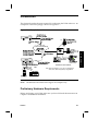
Preliminary Hardware Requirements
Preliminary Configuration Requirements
Specific Services
Initial Setup
Configure Protocols and Gateway Services —
srvsetup
Configure Default Route, DNS, and SNMP
Default Route – dftroute*
Domain Name Server – dns
SNMP Manager – snmp
Starting the LCS60
Base Level Backup
Configuration Changes
Administrative and Maintenance Commands
4
3-1
3-1
3-2
3-3
3-3
3-10
3-23
3-24
3-25
3-26
3-27
3-27
3-28
3-29
PPP – Configuration and
Administration
LCS60 Configuration and Connection for PPP Service
PPP Service Connection Dialstrings
Privately Administered Static IP Address
Reserved IP Address
Issue 2
2-22
2-22
2-22
2-24
2-25
2-25
2-27
2-27
2-28
2-29
2-29
2-29
4-1
4-13
4-15
4-16
iii
Table of Contents
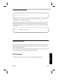
Dynamically Assigned IP Address
Administration
Show Session Examples
Call Trace Example
Log File
Related Commands
5
SLIP – Configuration and
Administration
LCS60 Configuration and Connection for SLIP Service
SLIP Service Connection Dialstrings
Privately Administered IP Address
Reserved IP Address
Dynamically Assigned IP Address
Administration
Stop Example
Call Trace Example
Errors
Log File
Related Commands
6
5-1
5-9
5-10
5-11
5-12
5-13
5-13
5-14
5-14
5-14
5-15
ARAP – Configuration and
Administration
LCS60 Configuration and Connection for ARAP
Service
ARAP Service Connection Dialstring
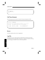
Administration
Show Service Example
Show Session Example
Call Trace Example
Log File
Related Commands
iv
4-17
4-18
4-18
4-20
4-21
4-21
6-1
6-5
6-5
6-5
6-6
6-6
6-7
6-7
Issue 2
Table of Contents
7
Gateway Services – Configuration and
Administration
LCS60 Configuration and Connection for Gateway
Service
Access to Gateway Services – Dialstrings
Telnet Service
Inactivity Timeout Option
Return to DESTINATION Option
User Information
Async-to-TCP Gateway Service
TCP-to-Async Gateway Service
UUCP Feature
Data Switch to LCS60 to LAN
LAN to LCS60 to Data Switch
Example UUCP Service Using SunOS 4.0
Example UUCP Service Using NCR 4.0
Administration
Service Ports
Trace TCP/Async
Error Messages
Log Files
8
Administration
Basics
Logging On
System Console
Remote Administration
lcsadm Interface
Common Commands
Initial System Setup (initsetup)
Top Directory Commands
Session Directory Commands
Ports Directory Commands
Service Directory Commands
Manager Directory Commands
Config Directory Commands
Issue 2
7-1
7-8
7-8
7-9
7-10
7-10
7-11
7-12
7-13
7-13
7-15
7-16
7-17
7-18
7-18
7-19
7-19
7-20
8-1
8-1
8-2
8-2
8-3
8-4
8-5
8-5
8-7
8-10
8-12
8-13
8-16
v
Table of Contents
Typical Administrative Tasks
Show Session Example
Log Level Example
Change the Default Route Example
Summary Output Examples
System Console Parameters– Autobaud
Backup and Restore Operations
Generic vs. Variable Files
Local and Remote Modes
Backup/Restore (Tape) – Local Mode
To Back Up to Tape
To Restore from Tape
To List the Contents of a Tape
Centralized Backup/Restore – Remote Mode
Security — Authorizing Clients and Servers
Access to Backup/Restore Functions – Clients and
Servers
Defining Backup/Restore Servers on a Client
Defining Backup/Restore Clients on the Server
Backup or Restore Functions
Creating a Tape
Network Access Password Option
Deleting the Network Access Password
Changing the Network Access Password
Status
Error Messages
Error Messages from the LCS60 Fiber Interface
Console Error Messages
Hardware Error Messages
Server Error Messages
Call Error Messages
Lucent Technologies Data Switch Server Log File
Additional Log Files
9
8-32
8-33
8-34
8-35
8-38
8-38
8-40
8-40
8-40
8-41
8-42
8-42
8-42
8-44
8-44
8-45
8-46
Maintenance
Reload System Software
UNIX System Software Installation
UFS Utility Fixes Tape Installation
inet Package Removal
vi
8-21
8-22
8-23
8-23
8-24
8-24
8-25
8-26
8-27
8-27
8-27
8-29
8-30
8-30
8-31
9-1
9-1
9-7
9-8
Issue 2
Table of Contents
LCS60 Application Software Installation
Removing the LCS60 Application Software
Upgrade
Remote Upgrade
Installing an Upgrade on a Remote Upgrade Client
Processor Board Firmware Update
Processor Diagnostics - MVME197
VMEDKHS Diagnostics
Connection Verification
LCS60 to Data Switch Connected Host Verification
(dkcu)
LCS60 to Data Switch Verification – Loopback Test
(dkcu)
LCS60 to Local Ethernet Host Verification (ping)
Memory Dump
After the Dump is Completed
A
srvtab
9-29
9-29
9-30
9-32
A-1
A-1
A-2
A-3
A-4
A-5
A-6
A-7
A-8
A-9
A-9
StarKeeper II NMS
Configuration of the StarKeeper II NMS
Diskette or Tape Installation
StarKeeper II NMS – Configuration Commands
Alarms to StarKeeper II NMS
Issue 2
9-28
Originating Group Security
Server Table
System Field
Service Field
Flags Field
User Field
Program Field
Initial Parms Field
Server Table Scanning Rules
Modifications to the Server Table
Server Table Validation and Matching
B
9-9
9-13
9-15
9-16
9-16
9-19
9-23
9-25
9-28
B-1
B-1
B-4
B-6
vii
Table of Contents
C
User Error Messages
Cable Error Message
Outgoing Call Error Messages
Incoming Error Messages
SLIP Sessions
D
Software Installation – Fujitsu or
Seagate ST5660N Drive
Reload System Software
UNIX System Software Installation
E
viii
C-1
C-1
C-9
C-10
D-1
D-1
Manual Pages
ATLOG
ATNETSTAT
ATPING
DKCU
DKMAINT
FTP
IFCONFIG
IFSTAT
IFTRACE
IPXNETSTAT
IPXPING
NETSTAT
NSLOOKUP
PING
PULL
PUSH
ROUTE
STATLCS
TELNET
E-1
E-2
E-4
E-6
E-8
E-9
E-19
E-21
E-24
E-26
E-27
E-28
E-30
E-34
E-35
E-37
E-40
E-42
E-43
Issue 2
Table of Contents
F
User Information
Introduction
Client Software Configuration
Client Packages
Mac Connection – CCL Script
CCL and Modem Hints
CCL
Modem
PPP Service Examples
Windows 95 – IPX over PPP
PC Configuration
PPP Connection
WIN PC/TCP 3.0
PC Configuration
PPP Connection
InterPPP
Connection
SLIP Service Examples
ChameleonNFS 4.0
ARAP Service Example
Connection (via Modem)
G
Glossary
Glossary
General
Parameters
AppleTalk Network/Zone (atalkas)
Ethernet Interface (etherif)
DNS Resolver (dns)
Define Service Sessions (maxsessions)
SLIP/PPP Service (ipas/ipx)
TCP-to-Asynchronous Gateway Services (srvports)
Subnetwork Configuration (subnet)
Report Fields
Session Directory
Ports Directory
Service Directory
Issue 2
F-1
F-1
F-2
F-2
F-5
F-5
F-6
F-6
F-6
F-7
F-9
F-9
F-9
F-11
F-14
F-14
F-19
F-19
F-22
F-22
G-1
G-1
G-3
G-3
G-4
G-5
G-5
G-5
G-6
G-7
G-8
G-8
G-16
G-17
ix
Table of Contents
Manager Directory
Server Directory
I
x
G-19
G-19
Index
Index
I-1
Issue 2
Figures
Figure 1-1:
Figure 1-2:
Figure 1-3:
Figure 1-4:
Figure 1-5:
Figure 2-1:
Figure 2-2:
Figure 2-3:
Figure 2-4:
Figure 2-5:
Figure 2-6:
Figure 2-7:
Figure 3-1:
Figure 3-2:
Figure 3-3:
Figure 4-1:
Figure 4-2:
Figure 5-1:
Figure 5-2:
Figure 6-1:
Figure 6-2:
Figure 7-1:
Figure 7-2:
Figure 8-1:
Figure 9-1:
Figure 9-2:
Figure F-1:
Figure F-2:
Figure F-3:
Figure F-4:
Figure F-5:
Figure F-6:
Figure F-7:
Issue 2
LCS60 as an AppleTalk Router
AppleTalk Virtual Zone
IPX Virtual Network
IP Routing with the LCS60
IP Address Assignment
Mounting the LCS60 Cabinet
MVME712M Header Locations and Factory Jumper Placements
System Console Connections – Direct
System Console Connections – through a Data Switch
System Console Connections – through Modems
System Console Connections – through StarKeeper II NMS
LCS60 Rear Panel AC Connections
Example Network
initsetup
srvsetup
Example Network – PPP Service
Configuring PPP Service for IP, IPX, and AppleTalk
Example Network – SLIP Service
Configuring SLIP Service
Example Network – ARAP Service
Configuring ARAP Service
Example Network – Gateway Services
Gateway Services Configuration
lcsadm Interface Directory Structure
Faceplates
Verifying Connections, Example Network
Windows 95 IPX Over PPP – Example Screens
Windows 95 IPX Over PPP – Connect To Example Screen
PC/TCP Example Screens
PC/TCP Session Configuration Screen Example
Network Control Panel
Modem Port and PPP Screens
IP Address Screen
1-8
1-8
1-9
1-14
1-16
2-7
2-10
2-12
2-16
2-17
2-18
2-26
3-1
3-4
3-10
4-1
4-2
5-1
5-2
6-1
6-2
7-1
7-2
8-4
9-23
9-28
F-8
F-8
F-12
F-13
F-16
F-16
F-17
xi
Table of Contents
Figure F-8: PPP Connection Screen
Figure F-9: AppleTalk Status Window
Figure F-10: Custom Interface Window
Figure F-11: Custom Setup Window
Figure F-12: Login Settings Window
Figure F-13: ARAP Remote Connection – Example
Figure F-14: ARAP Remote Access Setup – Connection Screen
Figure F-15: ARAP Remote Access Setup – Modem Example
Figure F-16: ARAP Remote Access Status Screen – Example
xii
F-18
F-18
F-19
F-20
F-20
F-23
F-23
F-24
F-25
Issue 2
Tables
Table 1-1:
Table 2-1:
Table 2-2:
Table 2-3:
Table 2-4:
Table 2-5:
Table 2-6:
Table 3-1:
Table 3-2:
Table 3-3:
Table 7-1:
Table 8-1:
Table 8-2:
Table 8-3:
Table A-1:
Table A-2:
Table A-3:
Issue 2
Online Manual Pages
Controls and Indicators
Specifications
Required Additional Equipment
System Console (and Port) Configuration
MVME712M Module Optioning
RS-232 Interface
Protocol and Services Commands
Configuration Commands – Config Directory
Administrative/Maintenance Commands – Config Directory
Gateway Services – Log Files
Start/stop Command Dependencies
Backup/Restore Functions
Log Files
Server Table Flags
User ID Mapping Options
Program Arguments Specification
1-21
2-2
2-3
2-5
2-9
2-10
2-11
3-9
3-28
3-29
7-20
8-7
8-35
8-47
A-4
A-6
A-7
xiii
Table of Contents
xiv
Issue 2
Screens
Screen 2-1: TY Configuration Dialogue
Screen 2-2: MSM Configuration Dialogue
Screen 3-1: LCS60 Top Directory
Screen 4-1: Configure IP Network Security Group – Example
Screen 4-2: Configure Reserved IP Address – Example
Screen 4-3: Configure IPX Parameters – Example
Screen 4-4: Configure AppleTalk Virtual Network – Example
Screen 4-5: Configure the Ethernet Interface – Example
Screen 5-1: Configure IP Network Security Group – Example
Screen 5-2: Configure Reserved IP Address – Example
Screen 5-3: Configure the Ethernet Interface – Example
Screen 6-1: Configure AppleTalk Virtual Network – Example
Screen 7-1: Gateway Service Configuration – Example
Screen 8-1: Top Directory
Screen 8-2: Session Directory
Screen 8-3: Ports Directory
Screen 8-4: Service Directory
Screen 8-5: Manager Directory
Screen 8-6: Server Directory
Screen 8-7: Config Directory
Screen 8-8: LCS60 Backup and Restore Configuration Menu
Screen 8-9: Backup/Restore Menu
Screen 8-10: Tape Backup Management Menu
Screen 8-11: Centralized Backup/Restore Menu – Server
Screen 8-12: Centralized Backup Server Definition Menu
Screen 8-13: Centralized Backup Client Definition Menu
Screen 8-14: Centralized Backup Operations Menu
Screen 8-15: Centralized Backup Operations Menu – Server
Screen 8-16: Tape Backup Management Menu – Server
Screen 8-17: TCP-to-Async Gateway with Network Access Password
Screen 9-1: How to Enter System Responses
Screen 9-2: UFS Utility Fixes Maintenance Tape Installation
Screen 9-3: inet Package Removal
Issue 2
2-13
2-14
3-5
4-3
4-5
4-7
4-10
4-12
5-3
5-5
5-7
6-3
7-4
8-5
8-8
8-10
8-12
8-14
8-15
8-17
8-26
8-28
8-28
8-32
8-33
8-34
8-35
8-36
8-38
8-39
9-2
9-7
9-8
xv
Table of Contents
Screen 9-4:
Screen 9-5:
Screen 9-6:
Screen 9-7:
Screen 9-8:
Screen D-1:
Screen F-1:
Screen F-2:
Screen F-3:
xvi
LCS60 Application Software Installation
LCS60 Application Software Removal – R2.0 Example
set and env Commands
Example diag cpm for CPM-HS Module
Service Menu
How to Enter System Responses
CCL Script – Example
Sample LCS60 dialup.scr
slip.ini File Fragment
9-9
9-14
9-22
9-26
9-31
D-2
F-3
F-10
F-21
Issue 2
1
Feature Description
Document Organization
1-1
Reference Documentation
1-2
1-3
1-3
1-4
1-4
1-4
Apple References
Gateway References
PPP References
SLIP Reference
Other References
Overview
Benefits
LAN Protocols
TCP/IP
Domain Name Server (DNS) Resolver
Simple Network Management Protocol (SNMP)
Routing Information Protocol (RIP)
AppleTalk Protocol
AppleTalk Network Number and Zone Assignment
IPX Protocol
IPX Virtual Network Assignment
Issue 3
1-4
1-5
1-6
1-6
1-6
1-6
1-7
1-7
1-8
1-9
1-9
i
Table of Contents
Remote Access Protocols
TCP/Async Gateway Service
TCP Service Ports
Serial Line IP (SLIP)
Point-to-Point Protocol (PPP)
Van Jacobson TCP/IP Header Compression
Compressed IPX Header (CIPX)
AppleTalk Remote Access Protocol (ARAP)
Multiple IP Subnetworks
ii
1-10
1-10
1-11
1-11
1-12
1-12
1-13
1-13
IP Routing
Security Groups
1-13
1-13
1-15
IP Address Assignment by the LCS60
1-17
Hardware Features
Enhanced Processor
Fiber Interface
1-17
1-17
1-18
Network Security
1-18
Copy Protection
1-19
Issue 3
Table of Contents
Administration
Issue 3
Backup/Restore
R3.0 Upgrade
Remote Upgrade
Centralized Network Management
1-19
1-19
1-20
1-20
1-20
Manual Pages
1-21
Customer Assistance
1-22
iii
Table of Contents
iv
Issue 3
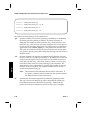
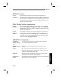
Document Organization
Features
This installation and administration guide is arranged as follows:
Feature Description
Chapter 1 describes the LCS60 and its supported services.
Hardware Installation
Chapter 2 gives all the information needed to install the
LCS60.
General Software
Configuration
Chapter 3 details the basic configuration procedures for
the LCS60 and gives examples of configuring the supported services (PPP, SLIP, ARAP, Gateway).
PPP Configuration
and Administration
Chapter 4 gives the specific instructions for configuring
and administering the PPP service.
SLIP Configuration
and Administration
Chapter 5 gives the specific instructions for configuring
and administering the SLIP service.
ARAP Configuration and Administration
Chapter 6 gives the specific instructions for configuring
and administering the ARAP service.
Gateway Services
Configuration and
Administration
Chapter 7 gives the specific instructions for configuring
and administering the Async-to-TCP service, including
details of the UUCP feature and the Telnet service.
Administration
Chapter 8 provides detailed instructions on administering the LCS60 system.
Maintenance
Chapter 9 provides maintenance procedures for reloading and removing the software, performing board diagnostics, and verifying connections.
Originating Group
Security
Appendix A briefly defines the originating group security built into the LCS60 using the srvtab files.
StarKeeper II NMS
Appendix B provides configuration instructions for the
StarKeeper II NMS and lists the LCS60 alarms reported
by the StarKeeper II NMS.
User Error Messages
Error messages that the user may encounter are listed in
Appendix C.
Issue 3
1-1
Features
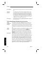
Document Organization
Software Installation
This appendix gives instructions for installing UNIX
System software on LCS60 machines with Fujitsu Drives
and with Seagate 5660N Drives.
Man Pages
Appendix E includes copies (listed alphabetically) of
selected man pages provided on-line with the LCS60.
User Information
Appendix F provides examples of software packages that
may be used with the LCS60. This appendix is provided
for the convenience of the user and is not an endorsement of any particular software package.
Glossary
A glossary of terms is provided.
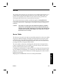
Reference Documentation
Note:
LCS60 users can obtain assistance to problems encountered while working on the system by calling the Customer Assistance Center (CAC)
HOTLINE: 1-800-WE2CARE.
Because it may be necessary to integrate the LCS60 with data switch and StarKeeper II NMS products, the following manuals are useful references:
StarKeeper II NMS User Guide, select code 255-114-707
Network Access Control (NAC) System Installation, Operations, and Maintenance Guide, select code 255-102-101
Datakit II VCS Node Reference, select code 255-115-220
BNS-1000 Node Reference, select code 255-190-220
BNS-2000 Node Reference, select code 255-191-220
CommKit Host Interface 386/486 Computers Installation and Administration
Guide, select code 255-110-115
1-2
Issue 3
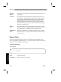
Reference Documentation
CommKit Internal Interface Specification, select code 700-283.
Order these manuals from the Customer Information Center, P.O. Box 19901
Indianapolis, IN 46219, 1-800-432-6600 (USA), 1-800-255-1242 (Canada),
1-317-352-8557 (other areas), or contact your Lucent Technologies account executive (AE).
Apple References
When using the LCS60 with AppleTalk or ARAP, the following references may
be useful:
Inside AppleTalk, Second Edition, G.S. Sidhu, et.al, Addison-Wesley Publishing (ISBN 0-201-55021-0).
AppleTalk Remote Access Modem Script Workshop – Software (contact Apple
Computer).
Gateway References
RFC 854, Telnet Protocol Specification
RFC 856, Telnet Binary Transmission
RFC 857, Telnet Echo Option
RFC 858, Telnet Suppress 60 Ahead Option
RFC 859, Telnet Status Option
RFC 860, Telnet Timing Mark Option
RFC 861, Telnet Extended Options - List Options
RFC 884, Telnet Terminal Type Option
Issue 3
1-3
Features
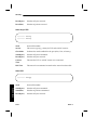
Data Networking Products and Services Ordering Guide, select code 255-100021.
Features
Reference Documentation
PPP References
RFC 1549, PPP in HDLC Framing
RFC 1548, The Point-to-Point Protocol (PPP)
RFC 1378, The PPP AppleTalk Control Protocol (ATCP)
RFC 1332, The PPP Internet Protocol Control Protocol (IPCP).
RFC 1552, The PPP Internetwork Packet Control Protocol (IPXCP).
RFC 1553, Compressing IPX Headers over WAN Media (CIPX).
SLIP Reference
RFC 1055, Nonstandard for Transmission of IP Datagrams over Serial Lines
(SLIP).
Other References
RFC 1213
Management Information Base for Network Management
of TCP/IP-based internets: MIB-II
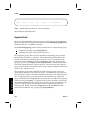
Overview
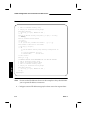
The LCS60 supports the following protocols:
• TCP/IP
• Serial Line IP (SLIP)
• Point to Point (PPP)
• AppleTalk
• AppleTalk Remote Access Protocol (ARAP)
• IPX
LAN to data switch connectivity between the resources of Ethernet LANs and
the data switch network is accomplished using the LCS60 (refer to Figure 3-1 for
an example of a data switch network).
1-4
Issue 3
Overview
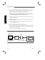
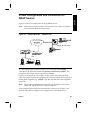
The LCS60 provides high-speed connectivity between Ethernet networks and the
Lucent Technologies family of data switches (Datakit II VCS 2.1 or greater, BNS1000, and BNS-2000).
Each LCS60 has the following components:
A CPU board to run the LCS60 software and to provide one Ethernet LAN
interface
A VMEDKHS board to provide a fiber interface to the data switch CPMHS trunk board
Communication between boards within the LCS60 is handled over a VME bus.
Benefits
The LCS60 expands the connectivity and enhances the functionality of the Lucent
Technologies data switch product line by allowing LAN and data switch network environments to communicate. Some of the benefits include:
Device-to-device connectivity over multiple LANs
Improved capability to develop and use distributed processing environments
Access through the most commonly used network protocols
Data switch network access to LAN data
Modular design which permits easy expansion as needs increase.
Issue 3
1-5
Features
The LCS60 provides the required hardware and software for the interface
between LAN and data switch network resources.
Features
LAN Protocols
TCP/IP
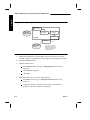
IP traffic is commonly associated with the Department of Defense (DOD) TCP/IP
suite and is often run over Ethernet LANs. The LCS60 allows asynchronous endpoints, such as a terminal or host connected to a data switch, to log onto any Ethernet TCP/IP LAN host by using the LCS60’s async-to-TCP gateway service. The
LCS60 provides the terminal user with an interface to the TCP/IP telnet command, which allows the network user to remotely log onto LAN hosts via a virtual terminal.
Conversely, an Ethernet TCP/IP LAN host can use the LCS60’s TCP-to-async
gateway service to access any asynchronous device (host, modem pool, etc.) connected to the data switch network. The LCS60 terminates the TCP/IP telnet
command initiated by the LAN host and provides the LAN user with asynchronous connectivity to the data switch network.
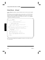
Domain Name Server (DNS) Resolver
The LCS60 can be configured as a Resolver in the DNS; this allows the LCS60 to
access a DNS Server for the translation of symbolic names into IP addresses.
This reduces the administration required for the LCS60. This feature provides a
less cumbersome and more efficient mechanism for performing translations
between symbolic host names and Internet addresses than checking the LCS60
database files.
The DNS function is a more manageable translation mechanism for large and
interconnected networks. It can connect to a name server (which maintains the
information database) on another host on the local or remote network.
The LCS60 default operating environment is still the use of the local host file. If
dns service is selected, the system will act as a resolver only.
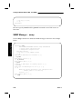
Simple Network Management Protocol (SNMP)
SNMP software allows the LCS60 to report its TCP/IP status to an SNMP
Manager. SNMP service can be started and stopped using the lcsadm interface
of the LCS60. Implicit in the SNMP architectural model is a collection of network
management stations and network elements. Network management stations execute management applications which monitor and control network elements.
Network elements are devices such as hosts, gateways, terminal servers, and the
1-6
Issue 3
LAN Protocols
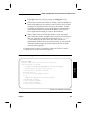
The LCS60 supports the standard SNMP management information base (MIB-II).
Refer to RFC 1213.
Supported Traps and MIBs
The generic traps that are supported are:
0 = cold start
2 = link down
3 = link up
4 = authentication failure
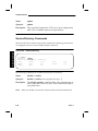
Routing Information Protocol (RIP)
The LCS60 supports RIP processing, i.e., handling IP routing information
through the use of routed. routed maintains the route table used by IP to determine the interface through which to send packets.
The LCS60 enables the administrator to start and stop routed service separately
using the lcsadm interface. In addition, the administrator can configure this service to be started at boot time.
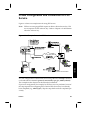
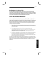
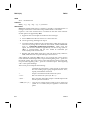
AppleTalk Protocol
The AppleTalk network system was developed to provide a link-independent
architecture to connect Apple and non-Apple network devices. AppleTalk provides a simple peer-to-peer protocol which allows any network device to communicate with any other network device running AppleTalk software.
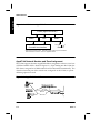
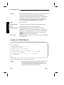
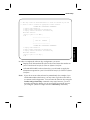
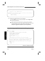
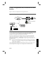
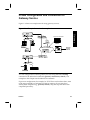
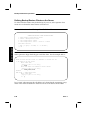
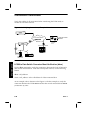
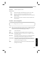
The LCS60 can be used as an AppleTalk router connecting the Ethernet LAN to a
virtual AppleTalk network. The virtual AppleTalk network created by the
LCS60 permits as many as 120 remote AppleTalk devices to dial in over the data
switch and connect to the AppleTalk internet. The virtual network on the LCS60
supports a single network number and zone name.
Issue 3
1-7
Features
like which have management agents responsible for performing the functions
requested by the network management stations. SNMP is used to communicate
management information between the network management stations and the
agents in the network elements.
Features
LAN Protocols
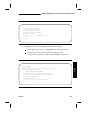
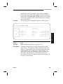
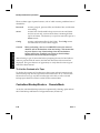
Figure 1-1: LCS60 as an AppleTalk Router
LCS60 (AppleTalk Router)
ARAP
PPP
CommKit Host Interface
ELAP*
Ethernet
* EtherTalk Link Access Protocol. EtherTalk is Apple’s data link protocol that allows
Ethernet cables to be used to connect an AppleTalk network.
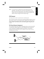
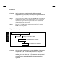
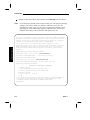
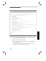
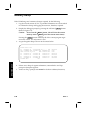
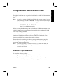
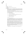
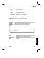
AppleTalk Network Number and Zone Assignment
The LCS60 supports dynamic AppleTalk address assignment within a virtual zone
of PPP and ARAP clients. (Refer to Figure 1-2.) Upon dialing into the LCS60, the
PPP client is assigned an available network and node number automatically. The
client then becomes part of the virtual zone configured on the LCS60; no special
dialstring options are used.
Figure 1-2: AppleTalk Virtual Zone
Mac
Lucent Data Switch
Network
LCS60
Mac
1-8
Issue 3
LAN Protocols
It is not necessary to configure the LCS60’s Ethernet interface for
AppleTalk. The LCS60 is not a seed router on the Ethernet. It will
discover the network range and the zones assigned to the Ethernet by
another router and will dynamically acquire a unique AppleTalk node
address within the assigned network number range.
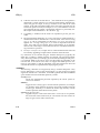
IPX Protocol
The IPX protocol is used to connect hosts in a Novell network.
The LCS60 can be used as an IPX router connecting the Ethernet LAN to a virtual
IPX network via PPP. The virtual IPX network created by the LCS60 permits as
many as 120 remote end hosts to dial in over the data switch and connect to the
Novell network. The virtual network on the LCS60 supports a single network
number.
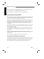
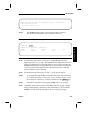
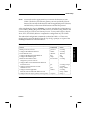
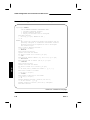
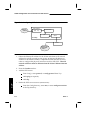
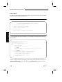
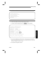
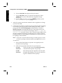
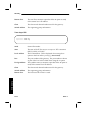
IPX Virtual Network Assignment
The LCS60 supports dynamic address assignment within a virtual network of IPX
over PPP clients. (Refer to Figure 1-3.) Upon dialing into the LCS60, the PPP
client is assigned an available IPX address automatically. The client then
becomes part of the virtual IPX network configured on the LCS60; no special
dialstring options are used.
Figure 1-3: IPX Virtual Network
Lucent Data Switch
Network
Issue 3
LCS60
1-9
Features
Note:
Features
Remote Access Protocols
TCP/Async Gateway Service
The LCS60 provides a gateway service such that a terminal user connected to the
data switch network either directly or through a modem can reach LANconnected hosts/workstations – this is the async-to-TCP gateway service. The
LCS60 provides communication in the other direction – from the LAN-host to
the data switch – with the TCP-to-async gateway service.
This connectivity is accomplished through the telnet and tcpsock commands
which allow communication between the data switch and LAN-host by means of
the TELNET protocol. Some features of this service are:
File Transfer. The LCS60 provides a mechanism for data switch to LAN
and LAN to data switch file transfer. A host connected to the data switch
network or to the LAN can initiate a file transfer (such as a uucp file
transfer) by including the dialstring for the LCS60 in its system files and
requesting TCP socket service. Both services provide an 8-bit TCP pipe as a
path for large file transfers; this pipe bypasses telnet which is slower.
Break character. The LCS60 recognizes the data-switch connected user’s
break character and converts it into a telnet IAC break character. From
the LAN, the LCS60 converts the telnet IAC BREAK sequence into an
URP* Level-D break toward the data switch connection.
Security. The LCS60 can be configured to drop the telnet connection if the
host to which the user is trying to telnet is unavailable. Without this
feature, trying to reach an unavailable host would result in putting the
user at the telnet> prompt and could possibly allow unauthorized connection to other LAN hosts. With this security feature, the connection is
taken down completely if the host is unavailable.
The LCS60 provides as many as 500 simultaneous telnet sessions (when no
PPP/SLIP/ARAP sessions are configured), which may be distributed in any way
between TCP-to-async and async-to-TCP sessions.
Note:
Simultaneous sessions are not necessarily all active.
Details of the telnet service are given in Chapter 7.
*
1-10
Refer to the CommKit Internal Interface Specification for details of the Universal Receiver Protocol (URP).
Issue 3
Remote Access Protocols
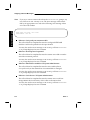
Refer to Chapter 7 for configuration of gateway services.
TCP Service Ports
A TCP service port is identified by a port number and can be customized to
streamline the transition from the TCP/IP network to the data switch network.
These ports can be configured with predefined destinations (PDDs), disconnect
options, window size changes, time limit options for the DESTINATION: prompt
and for data transmission, and customized destination prompts.
The number of TCP service ports is 500; each port can be defined with a unique
PDD offering the administrator enhanced flexibility in terms of the number of
data switch network connected hosts than can be contacted by each LCS60.
Serial Line IP (SLIP)
The LCS60 provides SLIP protocol capability to enhance dial-in access through
the data switch network. SLIP enables remote users to gain access to their internet and use familiar TCP/IP commands for most applications, e.g., file transfer,
electronic mail, and remote login.
SLIP allows a remote PC or Macintosh to logically reside on the TCP/IP LAN. In
a SLIP session, a remote user can dial into an LCS60, request SLIP service, and
receive an IP address automatically. This remote user is then logically connected
to the LAN and can execute such TCP/IP commands as ftp, telnet, and ping.
With the capability for automatic assignment of IP addresses, the LCS60 maintains a database of used addresses and the LCS60 administrator does not have to
pre-assign IP addresses to users. Static assignment of these addresses is still possible, however, for any situation where it may be necessary.
Issue 3
1-11
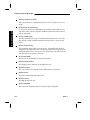
Features
The TCP gateway sessions take advantage of the highly efficient fiber interface
between the LCS60 and the data switch. With this service, any TCP/IP host that
can be reached on the LAN is accessible from the data switch network. For LAN
users, connection is generally provided through a DESTINATION: prompt, however, a TCP service port can be customized to bypass this prompt and automatically connect the LAN user directly to a particular data switch end point.
Features
Remote Access Protocols
The total combined number of remote access sessions – when SLIP, PPP, and/or
ARAP are configured – available through the LCS60 is 120.
Refer to Chapter 5 for configuration of the LCS60 for SLIP service.
Point-to-Point Protocol (PPP)
PPP provides point-to-point connectivity between a remote PC or Macintosh and
a LAN host, and is the industry standard. It is designed to carry multiple protocols such as TCP/IP, XNS, IPX, AppleTalk, and DECnet.
The remote PC or Macintosh negotiates the PPP protocol options with the LCS60
through the client software package residing on the PC or Mac. A remote user
can dial into the LCS60 through the data switch, request PPP service, and receive
an IP address, IPX address, and/or AppleTalk network and node number
automatically.
For TCP/IP, the IP address can be statically assigned, if needed (as it can be with
SLIP), and gives the remote user access to the TCP/IP network via commands
such as ftp, telnet, and ping.
For AppleTalk, a virtual AppleTalk address is assigned enabling the remote user
to access AppleShare and remote printer spooling services in various zones in
the network.
For IPX, a virtual IPX address is assigned. The remote user is viewed as a Novell
NetWare client and can therefore access file servers, printer servers, etc., in a
Novell network.
Refer to Chapter 4 for configuration of the LCS60 for PPP service.
Van Jacobson TCP/IP Header Compression
Negotiation of the TCP/IP header compression option is defined in RFC1332. If
your client package supports Van Jacobson Header Compression, then configure
this feature on your Mac or PC. The size of each packet can shrink up to 35
bytes, thereby giving your PPP session a significant performance boost.
1-12
Issue 3
Remote Access Protocols
Negotiation of the IPX header compression option is defined in RFC1553. If your
client package supports Compressed IPX Headers (CIPX), then configure this
feature on your PC. The size of each packet can shrink up to 34 bytes, thereby
giving your PPP session a significant performance boost.
AppleTalk Remote Access Protocol (ARAP)
ARAP is used to obtain direct access to AppleTalk resources at remote locations.
The LCS60 uses ARAP to provide connection between the CommKit Host Interface and Ethernet-connected AppleTalk devices.
A remote user can dial into the LCS60 through the data switch, request ARAP
service, and receive the AppleTalk network and node number automatically.
The remote user can access AppleShare and remote printer spooling services in
various zones in the network.
Refer to Chapter 6 for configuration of the LCS60 for ARAP service.
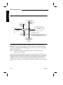
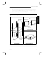
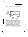
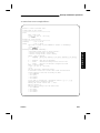
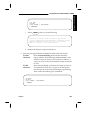
Multiple IP Subnetworks
IP Routing
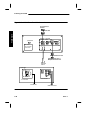
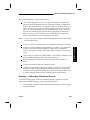
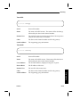
The LCS60 acts as an IP router with multiple IP network interfaces. Figure 1-4
shows an example of how an LCS60 might be configured, defining four virtual IP
subnetworks. Each interface has a unique IP subnetwork number that represents
a LAN segment. These numbers are allocated by the Network Administrator
during configuration of the LCS60.
Issue 3
1-13
Features
Compressed IPX Header (CIPX)
Features
Multiple IP Subnetworks
Figure 1-4: IP Routing with the LCS60
LAN Segment
Security Group: Techs
(virtual)
154.12.25
LAN Segment
Security Group: Library
(virtual)
154.12.24
Ethernet LAN
morse-e0
(physical)
154.12.21
Lucent Data Switch
Network
LCS60
morse
LAN Segment
Security Group: morse
(virtual)
135.12.23
CommKit Host Interface
Note: The numbers shown are IP network numbers.
The LCS60 reserves host address .1 for
each virtual LAN segment (e.g., 154.12.24.1).
LAN Segment
Security Group:Eng
(virtual)
154.12.26
The LCS60 has a physical IP network number for its Ethernet interface (e.g.,
154.12.21) and can have a virtual IP network number for each defined security
group (e.g., Library, morse, Techs, Eng), up to a maximum of four such groups
as shown in Figure 1-4.
Note:
The Ethernet IP network number and the four virtual IP network
numbers must be unique.
The LCS60 examines the destination address of every IP packet it receives over
the Ethernet and CommKit Host interfaces, and sends the packet on to the LAN
segment it matches. For this reason, all network numbers must be unique. For
example, for an IP packet with a destination address 154.12.24.50, the LCS60
morse would route the packet through LAN segment Library as shown in Figure
1-4.
1-14
Issue 3
Multiple IP Subnetworks
The LCS60 provides a mechanism for allocating IP addresses from one or more
pools of addresses. Each address pool is associated with a unique IP network
security group and is used to limit user access to the LAN.
This feature allows the LCS60 administrator to define up to four IP networks that
an LCS60 user can select when dialing in for either SLIP service or IP over PPP
service. Each IP network is associated one for one with a dkserver service name.
This name must be entered in the following databases:
LCS60 in which the dkserver name is referred to as an IP network security
group. One of these IP network security groups is required to match the
UNIX node uname value.
Data switch controller database as a local CPM host address, all associated
with the same CPM group.
Network Access Controller (NAC) as a host name (if security is required).
The NAC database is used to authorize members of a particular user group to
create calls to the LCS60 host name represented by the IP network security group
name. Generally, all those users who share common IP network access privileges
are assigned to a NAC user group; the NAC is set up to present the group
members a menu of LCS60 hosts they are permitted to call.
The IP routers connected to the same Ethernet LAN as an LCS60 are configured
to filter/secure IP traffic flow on the basis of an arriving packet’s source IP network address. A user’s source IP address is assigned by the LCS60 (or subject to
verification, it can be nominated by the user) when the SLIP or PPP session is
started.
An LCS60 is required to have an IP network security group whose name matches
the LCS60’s UNIX node name; this is referred to as the uname IP network security group. As a consequence, the ipas script requests that you configure the
uname security group’s IP network address before you are allowed to add any
other IP network security group. When editing the uname IP network security
group, the ipas script prevents you from altering its name; if you want to edit
this attribute, use the nodename script. Any change in the UNIX node name is
automatically applied to the uname IP network security group name and any of
its associated reserved IP addresses. You are not allowed to delete the uname IP
network security group because other LCS60 services depend on its dkserver
process being present.
Issue 3
1-15
Features
Security Groups
Features
Multiple IP Subnetworks
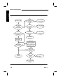
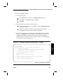
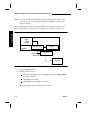
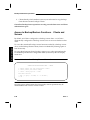
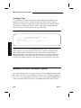
Figure 1-5: IP Address Assignment
Is this
IP address out
of range?
Incoming Call
Error: IP address
is not correct
Y
N
IP address
privately
administered
on PC?
Is this
IP address
busy?
Y
N
N
Was user
ID specified on
dialstring?
Is this
IP address
reserved?
Y
Error: IP address
is reserved
Y
N
Grant
requested IP
address
N
Set user id
to "guest"
-D option
on dialstring?
Error: IP address
is not available
Y
Search for
reserved IP address
with IP Network
security group name
and user ID name
N
Y
N
Find a
reserved IP
address?
Y
Assign
dynamic
IP address
Is the
reserved IP
address
busy?
N
assign reserved
IP address
Y
Error: IP address
is busy
1-16
Issue 3
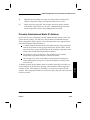
Multiple IP Subnetworks
PPP and SLIP users need to be assigned an IP address when they connect to the
LCS60, thereby allowing them to run TCP/IP applications over their serial connection. Figure 1-5 describes IP address assignment; refer to Chapter 4 (PPP) or
Chapter 5 (SLIP) for more information.
Note:
IP address assignment is defined in RFC1332.
The LCS60 has three mechanisms for assigning a SLIP or PPP user an IP address:
1 . Privately Administered Static IP Address. The user’s IP address is locally
administered by the user on his/her PC software package. The LCS60
will use the IP address requested by the PC package if it is valid and
unused.
2 . Reserved IP Address. This IP address, administered by the LCS60 administrator, is requested by specifying a zero IP address on the client software
package. A reserved IP address must exist in the LCS60 configuration
database before the session start up attempt.
3 . Dynamically Assigned IP Address. This IP address is randomly assigned by
the LCS60 from the IP network range associated with the particular IP
Network Security Group. A dynamic address may be requested on the
dialstring if no reserved IP address exists for a user ID.
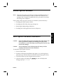
Hardware Features
Enhanced Processor
The LCS60 offers the enhanced Motorola MVME197 processor, rated at 100+
MIPS. With this processor, the LCS60 can sustain a higher number of sessions at
a greater aggregate throughput than its LCS50E predecessor.
Issue 3
1-17
Features
IP Address Assignment by the LCS60
Features
Hardware Features
Fiber Interface
The LCS60 supports a single multiplexed fiber interface to the data switch CPMHS module. This is a distinct advantage in terms of cable management and efficiency over traditional terminal servers which require separate asynchronous
connections.
Network Security
Complete network security is achieved through the Lucent Technologies Network Access Control (NAC) System. When a data-switch connected modem
accepts a call from a remote user, a PDD can force that user to authenticate
through a NAC. Once authenticated, the user can request a TCP gateway session
or a remote access session (such as ARAP, PPP, or SLIP) with an LCS60 by means
of a simple dialstring. From the LAN, all sessions bound for the data switch network can be forced to be authenticated by means of the TCP service port feature.
Additionally, the LCS60 supports a first-time authentication option with the
NAC. This option requires the LAN users to authenticate only once with the
NAC as long as the TCP/Async session remains open with the LCS60. The
actual duration time of an authenticated session is a NAC-dependent variable.
Therefore, consult the NAC documentation (refer to the section Reference Documentation in this chapter) for complete details on this feature.
1-18
Issue 3
Copy Protection
Administration
The LCS60 has its own local management software package called lcsadm. This
package allows a network administrator to configure services, administer service
sessions, and collect performance measurement data. This administration tool
can be accessed either through the LCS60 console port or through the multiplexed fiber interface.
Note:
The remote administration feature is delivered in the disabled state.
Instructions for enabling this feature are given in Chapter 8.
Backup/Restore
The LCS60 provides a backup/restore feature that allows an LCS60 to be configured as a backup/restore server. A backup/restore server can copy to its hard
disk (i.e., back up) a predefined set of files/directories from multiple remote
LCS60s (and LCS50Es) which are configured as backup/restore clients. The
backup/restore server can also be configured as its own client.
Note:
LCS60 R1.0 backups cannot be used to restore R3.0 systems.
The remote backup of clients is done disk-to-disk over the data switch network.
Backups and restores may be initiated either from a server or from a client.
This feature allows multiple backups of configuration files to be stored, and any
of several stored backups may be selected to be restored. Restores may be
comprehensive or selective, as required.
Issue 3
1-19
Features
This release of the LCS60 is copy-protected and requires a personalized software
key before it can be used. This number is assigned during the initial setup of the
LCS60 using the lcsadm interface (refer to Chapter 3 for complete details). The
copy-protection feature uses a release-specific software key; that is, Release 3 services can only be activated using the Release 3 key.
Features
Administration
R3.0 Upgrade
Previous releases of the LCS60 can be upgraded to Release 3.0. This requires
removing the software and any patches for the earlier release and installing the
R3.0 software from tape. Upgrade procedures are given in Chapter 9.
The configuration is automatically restored after installing R3.0; the user need
only configure new or changed services.
Note:
When upgrading from R1.0 or R2.0 to R3.0, you must have an R3.0
software key to activate R3.0 features. Refer to the section on Copy Protection.
Remote Upgrade
Upgrading multiple LCS60s to release 3.0 or greater can be done using the
remote upgrade feature. To upgrade several LCS60s to release 3.0 or greater, the
local tape drive need only be used to install the upgrade release on a single
LCS60 (the remote upgrade server). All other R2.0 or greater LCS60s in your
data switch network (remote upgrade clients) may then be upgraded remotely
across the data switch network.
Centralized Network Management
StarKeeper II NMS provides complete network management from one centralized location for both the data switch and the LCS60. The StarKeeper II NMS can
be located anywhere on the data switch network and can contact many LCS60
gateways.
1-20
Issue 3
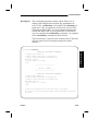
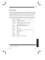
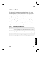
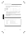
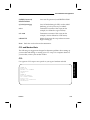
Manual Pages
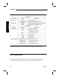
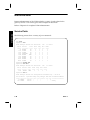
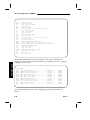
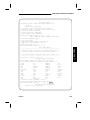
Table 1-1: Online Manual Pages
________________________________________________
________________________________________________
Commands
Protocol
Path
General
dkcu
/opt/dk/bin/dkcu
dkmaint
/opt/dk/sbin/dkmaint
ifstat
/usr/bin/ifstat
iftrace
/usr/etc/iftrace
push
/usr/bin/push
pull
/usr/bin/pull
________________________________________________
statlcs
/usr/etc/statlcs
TCP/IP
ftp
/usr/etc/ftp
ifconfig
/usr/etc/ifconfig
netstat
/usr/etc/netstat
nslookup
/usr/etc/nslookup
ping
/usr/etc/ping
route
/usr/etc/route
telnet
/usr/etc/telnet
________________________________________________
AppleTalk atlog
/usr/etc/atlog
atping
/usr/etc/atping
________________________________________________
atnetstat
/usr/etc/atnetstat
IPX
ipxping
/usr/etc/ipxping
________________________________________________
ipxnetstat
/usr/etc/ipxnetstat
The commands dkmaint and ifconfig are not used in normal LCS60 operations,
and should only be used by expert users and system administrators. These commands are not recommended except for troubleshooting purposes.
Access online man pages by executing the command:
Issue 3
1-21
Features
The LCS60 is provided with a set of online manual pages. Some commands that
may be of particular help to the system administrator are listed in Table 1-1 and
are included in Appendix E.
Features
Manual Pages
# man command
where command is the name of the command.
Customer Assistance
Technical support is available for the LCS60 from the Lucent Technologies Customer Technical Support Center at 1-800-WE2CARE.
For more information on these service offerings, or to establish a service account,
contact your Lucent Technologies account representative, or call 1-800-WE2CARE during our standard business hours (8AM – 5PM Eastern Time, Monday
through Friday, excluding holidays) and ask for the Data Networking Services
Operations department.
When you need assistance, call 1-800-WE2-CARE during the coverage period
selected when you established your service account. You will need to provide
your Service Account Number and identify the specific Lucent Technologies
Data Networking product for which you need assistance.
Outside the United States, Lucent Technologies Data Networking products and
support services are provided by Lucent Technologies subsidiaries and authorized value-added resellers. For more information, contact your sales representative.
1-22
Issue 3
2
Hardware Installation
Introduction
Controls and Indicators
Site Preparation
Space Requirements
Cabling
EMI Considerations
Required Equipment
Assembly
Unpacking
Installing the LCS60
Rack Mounting
Wall Mounting
Table-Top Mounting
Connecting the System Console
Serial Port Optioning (DTE/DCE)
Direct Connection to the LCS60
Connection through a Data Switch
Connection through Modems
Connection through StarKeeper II NMS
Connecting the Fiber Interface
Routing the Optical Fiber Cable
Installing the CPM-HS Module and Optical Fiber
Cable
Issue 3
2-1
2-1
2-2
2-4
2-4
2-5
2-5
2-6
2-6
2-6
2-6
2-8
2-8
2-9
2-9
2-12
2-12
2-17
2-17
2-19
2-19
2-20
i
Table of Contents
Configuration of the Lucent Technologies Data
Switch – LCS60
Dialogues
Enter Group Name
Define the Local Address for the LCS60
Configure the CPM-HS Module
Power and Grounding
Power-Up Procedures
Power-Down Procedures
Verify LCS60 Console Connection
Verify Fiber Connection
Configure the LCS60
LAN Connections
Ethernet
ii
2-21
2-22
2-22
2-22
2-24
2-25
2-25
2-27
2-27
2-28
2-29
2-29
2-29
Issue 3
Introduction
The LCS60 is supplied with the operating software already installed; therefore,
installation consists mainly of installing hardware and configuring the system.
The list below identifies the tasks, in the order that they should be performed, to
install and configure the product. These tasks are discussed in detail in the following sections.
1 . Mount the LCS60
Hardware
2 . Attach the console to the LCS60
3 . Connect the fiber between the LCS60 and the CPM-HS
4 . Configure the LCS60 in the data switch
5 . Power-up the LCS60
6 . Verify the LCS60 console connection
7 . Verify the LCS60 fiber connection
8 . Configure the LCS60 using the lcsadm interface (Chapters 3– 7)
9 . Verify connections between the LCS60 and LAN hosts and between the
LCS60 and data switch connected endpoints (Chapter 9).
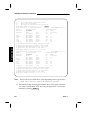
Controls and Indicators
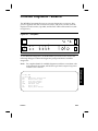
Table 2-1 lists the LCS60 controls and indicators.
Issue 3
2-1
Hardware
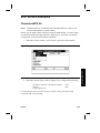
Introduction
Table 2-1: Controls and Indicators
______________________________________________________________________
Controls
______________________________________________________________________
Location
Switch
Function
______________________________________________________________________
Rear Panel
Power
________________________________________________________
Power ON/OFF
SYSTEM RESET Processor and VME bus reset
______________________________________________________________________
ABORT
Aborts program, returns to debugger
MVME197
________________________________________________________
RESET
______________________________________________________________________
Processor and VME bus reset
Indicators
______________________________________________________________________
Board
Indicator
Function
______________________________________________________________________
MVME197
FAIL
Hardware
failure
________________________________________________________
Indicates 197 board
SCON
is VME bus controller
________________________________________________________
RUN
Processor
run
state
________________________________________________________
LAN status
LAN
________________________________________________________
VME status
VME
________________________________________________________
SCSI
SCSI status
______________________________________________________________________
MVME712M ETHERNET XCVR Ethernet Transceiver
PWR STATUS*
power status (amber)
________________________________________________________
SCSI TERM
SCSI terminator
______________________________________________________________________
PWR STATUS*
power status (green)
*Can be seen by means of the rear panel cutout labeled SCSI INTERFACE.
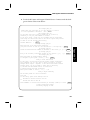
Site Preparation
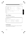
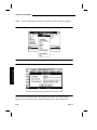
LCS60 specifications for the power, interface, and operating requirements, as
well as the other pertinent interface specifications, are listed in Table 2-2.
2-2
Issue 3
Site Preparation
Issue 3
Hardware
Table 2-2: Specifications
________________________________________________________
________________________________________________________
LCS60 Network Interface for Ethernet
90 to 132 VAC (47 to 63 Hz), 5 Amps
Power Requirements
180 to 250 VAC (47 to 63 Hz), 2.5 Amps
41
to
60
VDC,
8
Amps
Operating Temperature 10 to 45°C
−40 to 54°C
Storage Temperature
Operating Humidity
Long-Term 20 to 55%
Short-Term 20 to 80%
Storage Humidity
10 to 95%
________________________________________________________
Fiber Interface
________________________________________________________
Fiber Core Size
62.5 microns
Mode
Multi-mode
Fiber Optic Cable
FL2P-P Type
Connector
ST Type
________________________________________________________
________________________________________________________
Ethernet Interface
Interface
IEEE 802.3
________________________________________________________
Connector
Female 15-pin DB15
Console/Terminal Interfaces
________________________________________________________
RS-232C (limited) Asynchronous
Port 1 (console)
Ports 2,3,4 (terminal) RS-232C Asynchronous
Connectors
________________________________________________________
25-pin DB25 (receptacle)
________________________________________________________
Serial Port Defaults
Port 1
9600 bps
9600 bps
Port 2
Port 3
9600 bps
Port 4
________________________________________________________
1200 bps
2-3
Site Preparation
Space Requirements
Hardware
The LCS60 can be rack mounted, wall mounted, or installed on a secure surface.
The unit is 7 × 17 × 19 inches and weighs 40 lbs. A minimum of 12 inches of
clearance is required at the front and rear of the unit for access, and a minimum
of two inches of clearance at the sides of the unit to permit proper airflow
through the unit.
Cabling
WARNING:
Connect and disconnect cables ONLY when the power is off.
There are four types of connections commonly required for the LCS60:
1 . A dual optical fiber connection to a CPM-HS module installed in a Lucent
Technologies data switch or concentrator. The fiber cable between the
LCS60 and the data switch is limited to a maximum length of 2.9 km.
2 . Ethernet LAN connection.
3 . A console connection through an RS-232C interface to either a terminal or
data switch port. RS-232 distance limits apply to the LCS60 console connection (nominally 50 feet).
4 . An AC power connection is required for an AC powered unit. An AC
outlet must be within 6 feet of the LCS60; the use of extension cords
should be avoided.
5 . A DC power connection is required for DC powered units. The customer
must make this connection with wire no larger than 6 AWG and no
smaller than 18 AWG.
Cautions:
Do not run signal cables next to, or parallel with, AC power cables.
Do not run signal cables near radio transmitters or any equipment
that generates radio frequencies.
Do not run signal cables near electric motors, power supplies,
power line regulators, or relays.
Do not run signal cables near equipment that generates power line
noise; such as air conditioners, copy machines, and water coolers.
Use power outlets with adequate protective grounding.
2-4
Issue 3
Site Preparation
EMI Considerations
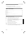
Required Equipment
The LCS60 is shipped in the hardware configuration ordered, the operating
software loaded, and user documentation included. Additional equipment
required for the initial installation of an LCS60 is listed in Table 2-3.
Table 2-3: Required Additional Equipment
___________________________________________________________________
___________________________________________________________________
Item
Description
Quantity
1
___________________________________________________________________
Fiber Pair
Lucent FL2P-P-[length]* (specified in feet)
1
RS-232
Length required to connect console to
___________________________________________________________________
(DB25) Cable
LCS60
1
Ethernet Transceiver Length required for connection from
___________________________________________________________________
(IEEE Cable)
LCS60 to Ethernet transceiver
(as reqd.) Horizontal Shelf,
Rack mounting hardware for additional
Slide Rails, or
support; provided by rack/cabinet
___________________________________________________________________
support brackets
vendor.
___________________________________________________________________
1 (as reqd.) ED5P183-33, G-40
Wall Mounting Kit for LCS60
1
CPM-HS module
Node connection
___________________________________________________________________
1
___________________________________________________________________
AWJ2
Paddleboard for the CPM-HS module
___________________________________________________________________
18 AWG — 6 AWG wire for DC powered unit only
(as reqd.) wire
* Formerly AT&T FL2P-P.
Issue 3
2-5
Hardware
The LCS60 can radiate radio frequency energy, and if not installed in accordance
with instructions, may cause interference to radio communications. This equipment has been tested and found to comply with the limits for a Class A computing device pursuant to Part 15, Subpart J of FCC Regulations, which are designed
to provide reasonable protection against such interference when operating in a
commercial environment. Operation in a residential area is likely to cause
interference, in which case the user must take whatever measures may be
required to correct the interference.
Assembly
Hardware
Unpacking
The LCS60 hardware comes fully assembled, with the exception of two handles
that mount on the front frame of the enclosure. After opening the shipping container, remove the documentation package, system software tapes and diskettes
and package of loose parts. Carefully remove the LCS60 unit. Open the front
cover of the LCS60 and check that the system is equipped as ordered and that all
circuit packs are fully seated in the LCS60 card cage.
Installing the LCS60
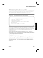
Follow the appropriate instructions (refer to Figure 2-1) to install the LCS60.
Rack Mounting
Mount the LCS60 in a 19-inch rack or cabinet using compatible mounting
hardware as shown in Figure 2-1. Mounting in a 23- or 25-inch rack or cabinet
requires a Bracket Extension Kit.
The front frame of the LCS60 has four mounting holes for securing the unit in a
standard 19-inch equipment rack. The weight of the LCS60 requires a shelf, slide
rails, or a support bracket. Contact the cabinet vendor for compatible hardware.
The handles for the LCS60 are shipped in a separate package within the main
shipping box. The handles can be attached to the front frame, with the handles
pointing away from the LCS60, using the four flat-head machine screws.
To rack mount the unit:
1 . Attach either a horizontal shelf, slide rails, or support brackets to the vertical uprights of the cabinet. For design compatibility, this hardware
should be purchased from the cabinet vendor.
2-6
Issue 3
Installing the LCS60
2 . With the horizontal support in place, slide the LCS60 into place. Fasten
the front frame of the LCS60 to the front uprights with four screws (23- or
25-inch cabinets require extension brackets).
Figure 2-1: Mounting the LCS60 Cabinet
Hardware
WALL
Cabinet
Rear uprights
TOP
Disk and tape drives
must be on top
..
....
.. . . .
.......
..
..
..
..
..
..
..
.
. .. . . . .
LCS60 mounts inside
Wall Mount Assembly
BOTTOM
Front
Frame
..
..
Wall Mount Assy.
mounts to wall
WALL MOUNT
Front
Cabinet
Front Uprights
Horizontal shelf,
slide rails, or
support brackets
required
RACK MOUNT
Issue 3
TABLE TOP MOUNT
2-7
Installing the LCS60
Wall Mounting
Wall mounting the LCS60 requires a Wall Mount Assembly to position the unit
vertically as shown in Figure 2-1.
Hardware
Wall mounting requires a surface 45 inches wide by 21 inches high covered by a
securely-fastened ¾-inch plywood sheet (or a comparably stable mounting surface).
The handles for the LCS60 are shipped in a separate package within the main
shipping box. If desired, attach the handles to the front frame, with the handles
pointing away from the LCS60, using the four flat-head machine screws.
To wall mount the unit:
1 . Using the Wall Mounting Assembly as a template, mark the location of
the four mounting holes on the plywood sheet. Drill the pilot holes or
install appropriate anchors, as required.
Note:
To function properly, the LCS60 must be positioned in the Wall Mount
Assembly with the disk and tape drive on top, the bottom surface
toward the wall, and the front cover of the LCS60 to the left.
2 . Attach the Wall Mounting Assembly to the plywood surface, using four ¼
x ¾-inch lag screws.
3 . Locate the LCS60 in the mounting assembly by aligning the front flange of
the LCS60 with the four threaded holes on the flange at the left end (facing
the assembly). Secure the LCS60 to the assembly, using the four M6 x
12mm screws included with the Wall Mount Assembly.
Table-Top Mounting
The handles for the LCS60 are shipped in a separate package within the main
shipping box. Attach the handles to the front frame, with the handles pointing
away from the LCS60, using the four flat-head machine screws.
Install the LCS60 on a stable surface with the required clearance as described previously under Space Requirements.
2-8
Issue 3
Installing the LCS60
Connecting the System Console
WARNING:
Connect and disconnect cables ONLY when the power is off.
The LCS60 uses a system console to run diagnostics, receive error messages, and
for administration. Configure the console as shown in Table 2-4.
Hardware
Table 2-4: System Console (and Port) Configuration
__________________________________
__________________________________
9600 bps
Baud Rate
Flow Control XON/XOFF
__________________________________
__________________________________
Data Bits
8, no parity
Stop Bits
1
__________________________________
Local Echo
__________________________________
None (full duplex)
The LCS60 has four serial RS-232 ports which can emulate asynchronous DTE or
DCE. Serial Port 1 is used for the LCS60 system console and operates at 9600
bps. Ports 2, 3, and 4 can be used to interface asynchronous terminals to the
LCS60 UNIX System with Ports 2 and 3 providing 9600 bps operation and Port 4
providing 1200 bps operation. The system console must be an asynchronous
ASCII terminal or PC (with terminal emulator). We recommend using a system
console with scrolling capability. The system console can be connected directly,
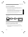
through a Lucent Technologies data switch, through modems (9600 bps), or
through StarKeeper II NMS.
Connect the system console to the LCS60 using one of the four connection
methods described in the following sections.
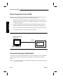
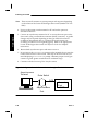
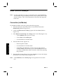
Serial Port Optioning (DTE/DCE)
Direct- and network-connected system consoles require Serial Port 1 to be
optioned to emulate DCE for connection to an external DTE device (this is the
default). If connection is through modems (DCE), Serial Port 1 must be optioned
to emulate DTE. Refer to Figure 2-2 and Table 2-5 for optioning information; see
Table 2-6 for DTE and DCE emulation and pin assignments for RS-232C interfaces.
Issue 3
2-9
Hardware
Installing the LCS60
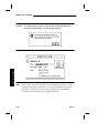
Table 2-5: MVME712M Module Optioning
_____________________________________________________
_____________________________________________________
Default Optioning
Ext.Interface
Port Emulation
Port
Jumper
Bridged Pins
_____________________________________________________
_____________________________________________________
DTE
DCE
all
1 J1
DTE
DCE
2 J16
all
_____________________________________________________
DTE
DCE
3
J13
all
_____________________________________________________
_____________________________________________________
DCE
DTE
all
4 J19
J15
no jumpers
_____________________________________________________
_____________________________________________________
Non-Default Optioning
DCE
DTE
1
J11
all
_____________________________________________________
DCE
DTE
all
_____________________________________________________
2 J17
_____________________________________________________
DCE
DTE
3 J14
all
DTE
DCE
4
J18
all
_____________________________________________________
_____________________________________________________
J15
no jumpers
Figure 2-2: MVME712M Header Locations and Factory Jumper Placements
2
J20
20
•• •• •• •• •• •• •• •• •• ••
J11
2 • ••••
1 • •• • • • • ••
J1
2
1
J14
14 2 • • • • • •
13 1 • • • • • •
J13
14 2
13 1
R3
R2
R1
13
25
13
25
2-10
J7
J9
1
14
1
14
1 J17
14 2 • • • •
•• 13 1 • •• • • • ••
J16
14 2
13 1
19
•• 14 2
13 1
J19
J8
J10
2 • • • • • • • • • • • • • • • • • • • • • • • • • 50
1 • • • • • • • • • • • • • • • • • • • • • • • • • 49
J3
A1
C1
14
13
J18
14 2 • • • • • • • 14
13 1 • • • • • • • 13
R4
J15
2 • • • • • • 12
1 • • • • • • 11
13
25
13
25
1 J21 6
••• •••
R7
R6
C1
R5
1
14
1
14
1
J6
R8
C2
8 1
R9
C3
8 1
R10 8
1
2
J5
49
50
DS1 DS2
8
15
A32
C32
J2
1
0
18
36
1
19
Issue 3
Installing the LCS60
Issue 3
2-11
Hardware
Table 2-6: RS-232 Interface
___________________________________________________________________
___________________________________________________________________
Pin Designation
Direction
Function
BA
Port 1
2
TD-Transmit Data
To DCE
BB
3
RD-Receive Data
From DCE
CA
Async DTE 4
RTS-Request To Send
To DCE
5
CTS-Clear To Send
From DCE
CB
Emulation 7
AB
Signal Ground
CD
___________________________________________________________________
20
DTR-Data Terminal Ready To DCE
___________________________________________________________________
Pin Designation
Function
Direction
Port1
2
From DTE
BA
TD-Transmit Data
BB
3
RD-Receive Data
To DTE
CA
Async DCE 4
RTS-Request To Send
From DTE
CB
5
CTS-Clear To Send
To DTE
Emulation 6
DSR-Data Set Ready
To DTE
CC
7
AB
Signal Ground
CF
___________________________________________________________________
8
DCD-Data Carrier Detect To DTE
___________________________________________________________________
Pin Designation
Function
Direction
Ports 2, 3, 2
To DCE
BA
TD-Transmit Data
BB
3
RD-Receive Data
From DCE
CA
and 4
4
RTS-Request To Send
To DCE
CB
5
CTS-Clear To Send
From DCE
Async DTE 7
Signal Ground
AB
8
CF
DCD-Data Carrier Detect
From DCE
Emulation 20
CD
___________________________________________________________________
DTR-Data Terminal Ready To DCE
___________________________________________________________________
Pin Designation
Function
Direction
Ports 2, 3, 2
From DTE
BA
TD-Transmit Data
BB
3
RD-Receive Data
To DTE
CA
and 4
4
RTS-Request To Send
From DTE
CB
5
CTS-Clear To Send
To DTE
Async DCE 6
DSR-Data Set Ready
To DTE
CC
7
AB
Signal Ground
CF
Emulation 8
DCD-Data Carrier Detect To DTE
CD
___________________________________________________________________
20
DTR-Data Terminal Ready From DTE
Installing the LCS60
Direct Connection to the LCS60
To connect an asynchronous terminal or PC directly to the LCS60 for use as an
LCS60 console, refer to Figure 2-3 and follow the steps below:
Hardware
1 . Serial Port 1 should be optioned to emulate DCE operation. This is the
default; therefore, if you haven’t changed anything there will be no need
to change the option.
2 . Connect a 25-pin RS-232 cable between the LCS60 rear panel connector
labeled "Serial Port 1" and an asynchronous terminal or PC (Figure 2-7).
3 . Power-up the system console and set the options as directed in Table 2-4.
4 . Continue with the Connecting Fiber Interface section.
Figure 2-3: System Console Connections – Direct
Asynchronous
Terminal
DCE
Console
Port
LCS60
Connection through a Data Switch
To connect an asynchronous terminal or PC to the LCS60 for use as a system console through a data switch network, refer to Figure 2-4 and follow the steps
below:
Note:
2-12
Connections to the data switch network must be to an asynchronous port
(e.g., a TY-12 port).
Issue 3
Installing the LCS60
1 . Serial Port 1 should be optioned to emulate DCE operation. This is the
default; therefore, if you haven’t changed anything there will be no need
to change the option.
2 . Connect the LCS60 rear panel connector labeled "Serial Port 1" to an asynchronous port using a straight-through connection (D8AH connector);
connect the 25-pin end to the LCS60.
a . Configure a group on the data switch network for the asynchronous port
connected to the LCS60
b . Configure a name pointing to this group which can be used to access the
LCS60 console port. (Refer to the appropriate Lucent Technologies data
switch Node Reference Guide for complete instructions.)
Note:
If you already have a terminal attached to the data switch that has a DESTINATION prompt, skip to step 7.
Screen 2-1: TY Configuration Dialogue
CC0> enter group
GROUP [up to 8 chars]: gmorscon
TYPE [local, trunk: +(local)]: local
DIRECTION [originate, receive, 2way]: receive
DEVICE OR HOST [up to 8 chars]: morscon
HOST AUTOBAUD [on, off: +(off)]: off
ROUND ROBIN SERVICE [per_port, per_module, none: +(none)]:
Creating New Host: morscon
GROUP [up to 8 chars]:
Delete
CC0> enter ty
TY TYPE [12 or ba12]: 12
MODULE ADDRESS: 18
Issue 3
Return
2-13
Hardware
3 . Configure the asynchronous port on the data switch according to Table
2-4 as a receiving group. Conduct the dialogues shown in Screen 2-1 or
2-2 on the data switch console to:
Installing the LCS60
Hardware
Screen 2-1: continued
PORT NUMBER [1-12: +(1-12)]: 11
COMMENT [up to 60 chars double quoted]:
"console for lcs60 morse"
SERVICE TYPE[console, dialer, host, modem, 2way, or terminal:+(terminal)]: console
GROUP [up to 8 chars]: gmorscon
BAUD RATE [300, 1200, 9600, ext, auto: +(9600)]:
Return
EXTERNAL BAUD RATE [2400, 4800, 19200: +(2400)]:
Return
PARITY [off, even, odd: +(off)]:
Return
FLOW CONTROL OF TY-12 BY DEVICE [xon_xoff, eia, none: +(none)]:
Return
FLOW CONTROL OF DEVICE BY TY-12 [xon_xoff, eia, none: +(xon_xoff)]:
Return
IS AN AT&T VDM CONNECTED TO THIS LINE [yes, no: +(no)]:
Return
TY TYPE [12 or ba12]:
Delete
CC0> enter address
LEVEL [local, area, exchange, local, speedcall: +(local)]: local
TYPE [numeric, mnemonic, both: +(mnemonic)]:
Return
MNEMONIC ADDRESS [up to 8 chars]: morscon
PAD SUPPORT [yes, no: +(no)]:
Return
DIRECTORY ENTRY [up to 30 chars double quoted, none: +(none)]:
"console to morse"
GROUP(S) [up to 4 groups separated by commas, none: +(none)]:
gmorscon
ORIGINATING GROUP NAME SECURITY PATTERN(S)
[comma-separated pattern list, same_as, none: +(none)]:
Return
INITIAL SERVICE STATE [in, out: +(out)]: in
LEVEL [network, area, exchange, local, speedcall: +(local)]:
Delete
CC0> restore ty
MODULE ADDRESS: 18
PORT NUMBER [1-12]: 11
CC0>
Screen 2-2: MSM Configuration Dialogue
CC0> enter group
GROUP [up to 8 chars]: gmorscon
TYPE [local, trunk: +(local)]: local
2-14
Issue 3
Installing the LCS60
Screen 2-2: continued
Hardware
DIRECTION [originate, receive, 2way]: receive
DEVICE OR HOST [up to 8 chars: +(standard)]: morscon
HOST AUTOBAUD [on, off: +(off)]: off
ROUND ROBIN SERVICE [per_port, per_module, none: +(none)]:
Return
Creating New Host: morscon
CC0> enter msm
COMPONENT [module, port]]: p
MODULE ADDRESS: 18
PORT NUMBER [1-12: +(1-12)]: 11
CC0> enter group
GROUP [up to 8 chars]: gmorscon
CONNECTED TO 2-WIRE MODEM [yes, no: +(no)]:
Return
BAUD RATE [75, 110, 150, 300, 1200, 2400, 4800, 9600, 14400
19200, 28800, 38400, 57600, 76800, 115200: +(9600)]:
Return
PARITY [off, even, odd: +(off)]:
Return
FLOW CONTROL OF MSM BY DEVICE [xon_xoff, eia, none: +(eia)]: none
FLOW CONTROL OF DEVICE BY MSM [xon_xoff, eia, none: +(eia)]: xon
VDM ON THIS PORT [yes, no: +(no)]:
Return
PERMANENTLY ACTIVATED PORT [yes, no: +(no)]: y
BITS PER CHARACTER [5, 6, 7, 8: +(8)]:
Return
NUMBER OF STOP BITS [1, 1.5, 2: +(1)]:
Return
ENDPOINT NUMBER OR RANGE [0000-9999, none: +(none)]:
Return
PORT NUMBER [1-12: +(1-12)]:
Delete
CC0> enter address
LEVEL [local, area, exchange, local, speedcall: +(local)]: local
TYPE [numeric, mnemonic, both: +(mnemonic)]:
Return
MNEMONIC ADDRESS [up to 8 chars]: morscon
PAD SUPPORT [yes, no: +(no)]:
Return
DIRECTORY ENTRY [up to 30 chars double quoted, none: +(none)]:
"console to morse"
GROUP(S) [up to 4 groups separated by commas, none: +(none)]:
gmorscon
ORIGINATING GROUP NAME SECURITY PATTERN(S)
[comma-separated pattern list, same_as, none: +(none)]:
Return
INITIAL SERVICE STATE [in, out: +(out)]: in
LEVEL [network, area, exchange, local, speedcall: +(local)]:
Delete
CC0> restore msm
COMPONENT [module, port]]: p
MODULE ADDRESS: 18
PORT NUMBER [1-12: +(1-12)]: 11
CC0>
Issue 3
2-15
Installing the LCS60
Note:
There are small variations in system prompts and responses depending
on the release of the Lucent Technologies data switch (Datakit II VCS or
BNS).
Hardware
4 . Power-up the system console terminal or PC and set the options as
directed in Table 2-4.
5 . Connect an asynchronous terminal or PC to an asynchronous port on the
data switch, using a null-modem connection (D8AG connector). A gender
changer may be required depending on the type of RS-232 connector
available on the terminal device. Configure the asynchronous port
according to Table 2-4 as an originating group. Refer to the appropriate
Lucent Technologies data switch Node Reference Guide for complete
instructions.
6 . Restore both asynchronous ports and name to service.
7 . In response to the DESTINATION prompt on the terminal device, enter the
name created for the LCS60 console. This step can be done from any terminal displaying a DESTINATION prompt. Maintain proper security precautions to guard against unauthorized or accidental usage.
8 . Continue with the Connecting Fiber Interface section.
Figure 2-4: System Console Connections – through a Data Switch
Asynchronous
Terminal
Data Switch
DCE
Asynchronous
Port
2-16
Console
Port
LCS60
Issue 3
Installing the LCS60
Connection through Modems
To connect an asynchronous terminal or PC to the LCS60 for use as a system console by means of modems, refer to Figure 2-5 and follow the steps below:
1 . Option Serial Port 1 to emulate DTE operation. (Refer to the section Serial
Port Optioning earlier in this chapter.)
3 . Power up the system console and set options as directed in Table 2-4.
4 . Continue with the Connecting Fiber Interface section.
Figure 2-5: System Console Connections – through Modems
Asynchronous
Terminal
Modem
Modem
DTE
Console
Port
LCS60
Connection through StarKeeper II NMS
For the StarKeeper II NMS connection (Figure 2-6), follow the steps below:
1 . Serial Port 1 should be optioned to emulate DCE operation. This is the
default; therefore, if you haven’t changed anything there will be no need
to change the option.
Issue 3
2-17
Hardware
2 . Connect the LCS60 rear panel connector labeled "Serial Port 1" to an asynchronous terminal by means of modems using straight-through RS-232
cabling. Modems must operate asynchronously at 9600 bps.
Installing the LCS60
2 . Connect the LCS60 rear panel connector labeled "Serial Port 1" to an asynchronous port on the data switch using a straight-through connection
(D8AH connector); connect the 25-pin end to the LCS60.
Hardware
3 . Configure the asynchronous port on the data switch according to Table
2-4 as a receiving group. Conduct the dialogue shown in Screen 2-1 (TY12) or Screen 2-2 (MSM) on the data switch console to:
a . Configure a group on the data switch network for the asynchronous port
connected to the LCS60
b . Configure a name pointing to this group which can be used to access the
LCS60 console port.
Refer to the appropriate Lucent Technologies data switch Node Reference
Guide for complete instructions.
4 . Restore the asynchronous port and name to service.
5 . Log on to StarKeeper II NMS; execute dkcu to the call address created for
the LCS60 console. Maintain proper security precautions to guard against
unauthorized or accidental usage.
6 . Continue with the Connecting Fiber Interface section.
Figure 2-6: System Console Connections – through StarKeeper II NMS
Asynchronous
Terminal
Data
Switch
StarKeeper
II NMS
CPM-HS
2-18
DCE
Console
Port
Asynchronous
Port
LCS60
Issue 3
Installing the LCS60
Connecting the Fiber Interface
Connection to the data switch network for data communications is by means of a
dual optical fiber cable. The network LCS60 fiber connection must be to a CPMHS module in a Datakit II VCS or BNS.
For network connection follow the steps below:
The optical fiber cable may be run in suspended ceilings, subfloor cable runs, and
riser shafts up to 500 feet. Before routing the cable, connect rubber caps to each
end of the cable to protect it from dirt and dust during installation.
Note:
Tools and hardware used to install copper wire and cable in building
duct and conduit systems are satisfactory for use in installing optical
fiber cable (such as, fish wire, woven cable grips, or rope). If woven
cable grips are used with fiber optic cables, tape them to the cable jacket
before pulling the cable.
When routing the cable, keep it away from copper riser cables. If this is not possible, install an inner liner (conduit or innerduct) to keep the cables separated.
EFT corrugated tubing (or equivalent) can be used; this tubing comes in short
lengths and can be bent.
Caution:
Optical fiber cables are not intended for use in air-handling ceiling
areas unless installed in approved conduit.
When installing the cable, avoid tight pulls or tugs against sharp corners of
framework. If cables are to be installed around sharp edges of cabinetry or
framework, cover the edges with split tubing or similar material. Observe the
minimum bending radius and maximum pulling tension specifications when routing
the dual optical fiber cables. When lacing or securing the cable, use flat lacing
twine or cable ties and do not tie the cable too tightly or microbending losses
may occur. Bundles of cables should not hang or protrude into the work space.
Wrap the cables in loops not less than 6 inches in diameter.
The optical fiber cable is not designed for conduit installation, but can be
installed in conduit if:
Issue 3
2-19
Hardware
Routing the Optical Fiber Cable
Installing the LCS60
Cables are placed in a single conduit having not less than ¾-inch inner
diameter
Hardware
The pull force on an optical fiber cable does not exceed 50 pounds per
cable.
Optical fiber cables should not be pulled through more than four 90-degree
bends, if more than four such bends are required, provide intermediate help
points. The minimum recommended conduit bend radius is 4-½ inches. Under
no circumstances should the cable be pulled around a sharp corner such as a
junction box connection.
Pulling tension during conduit installation can be minimized by:
Having the cable enter the end of the conduit nearest the curved sections.
Freeing ducts or conduits of foreign obstructions before cable installation.
Using approved polyvinylchloride (PVC) lubricants. Approved lubricants
are:
• Polywater A&C Lubricant
• Neutral soft soap
• Hydralube Blue Lubricant
• Talcum powder
Installing the CPM-HS Module and Optical Fiber Cable
1 . Slide the I/O distribution board (paddleboard) into one of the available
backplane slots from the rear of the data switch cabinet.
2 . Connect the paddleboard to the chassis.
3 . Slide the CPM-HS module into the same number slot as the paddleboard
from the front of the data switch cabinet.
4 . Connect the optical fiber cable as follows:
Note:
The length of the optical fiber cable between the data switch and the
LCS60 should not exceed 2.9 km.
Remove the rubber caps from the optical fiber cable that runs from the
transmitter side of the LCS60 and connect the optical fiber cable to the
receiver side (top connector) of the CPM-HS module in the data switch.
2-20
Issue 3
Installing the LCS60
Remove the rubber caps from the optical fiber cable that runs from the
receiver side of the LCS60, and connect the optical fiber cable to the
transmitter side (bottom connector) of the CPM-HS module in the data
switch.
5 . Set the MODE toggle switch on the CPM-HS faceplate to ENABLE.
6 . Set the Loopback switch on the CPM-HS paddleboard to NORM.
Configuration of the Lucent Technologies Data Switch
– LCS60
Configuration of the CPM-HS module in the data switch is done in the same way
as a CPM-HS module connected to a UNIX System host. The number of channels should be the same as the number of channels with which the LCS60 is configured, 512.
The first local address entered must match the first IP Network Security Group’s
name. Subsequent local addresses should match the other IP Security Group
names entered into the LCS60 configuration database. The LCS60 supports up to
four IP Network Security Groups. The first local address should be the same as
the node name of the LCS60. Additional information on creating the local
address group, and CPM-HS entries can be found in the Lucent Technologies
data switch documentation.
After the CPM-HS module is plugged into the data switch, the CPM-HS module
must be configured from the data switch console. The Network Administrator
enters the group name and local address for the LCS60, and configures the
CPM-HS module. The following tasks are performed at the data switch console:
Enter group name
Define the local address for the LCS60
Configure the CPM-HS module.
Sample dialogues (see also Figure 3-1) for these tasks are described below.
Issue 3
2-21
Hardware
If the cable is installed backwards, no harm will be done when powering
up.
Note:
Installing the LCS60
Dialogues
Note:
Dialogues differ depending on the data switch and release.
Hardware
Enter Group Name
CC0> enter group
GROUP [up to 8 chars]: morse
TYPE [local, trunk: +(local)]: local
DIRECTION [originate, receive, 2way]: 2way
DEVICE OR HOST [up to 8 chars]: morse
PASSWORD [up to 8 chars, none: +(none)]:none
ROUND ROBIN SERVICE [per_port, per_module, none: +(none)]: none
GROUP [up to 8 chars]:
Delete
CC0>
Conduct the appropriate dialogue as shown in screen above. (Enter Delete to
end the session.) The entries are described below:
group
Defines the group name by which the data switch knows the
LCS60. This is morse in the example. This must be the same as
the LCS60 node name.
type
The LCS60 is a local connection to the data switch (the CPM-HS
module resides in this data switch).
direction
The fiber interface may be used to originate and receive calls
through the CPM-HS module, therefore, it is 2way.
device/host
We recommend the name be the same as the name of the LCS60.
password
Passwords are not used with the CPM-HS module.
round robin
Choose the default of none.
Define the Local Address for the LCS60
Note:
You must enter an address for each IP Network Security group on the
node with a group name of the default node.
Conduct the appropriate dialogue as shown in the screen below.
2-22
Issue 3
Installing the LCS60
Hardware
CC0> enter address
LEVEL [local, area, exchange, local, speedcall: +(local)]: local
TYPE [x121, mnemonic, both: +(mnemonic)]: mnemonic
MNEMONIC ADDRESS [up to 8 chars]: morse
PAD SUPPORT [yes, no: +(no)]:
Return
DIRECTORY ENTRY [up to 30 chars double quoted, none: +(none)]:
"name of the LCS60"
GROUP(S) [up to 4 groups separated by commas, none: +(none)]:
morse
ORIGINATING GROUP NAME SECURITY PATTERN(S)
[comma-separated pattern list, same_as, none: +(none)]: Return
INITIAL SERVICE STATE [in, out: +(out)]: in
LEVEL [local, area, exchange, local, speedcall: +(local)]: local
TYPE [x121, mnemonic, both: +(mnemonic)]: mnemonic
MNEMONIC ADDRESS [up to 8 chars]: Library
PAD SUPPORT [yes, no: +(no)]:
Return
DIRECTORY ENTRY [up to 30 chars double quoted, none: +(none)]:
"name of the LCS60"
GROUP(S) [up to 4 groups separated by commas, none: +(none)]:
morse
ORIGINATING GROUP NAME SECURITY PATTERN(S)
[comma-separated pattern list, same_as, none: +(none)]: Return
LEVEL [local, area, exchange, local, speedcall: +(local)]:
local
INITIAL SERVICE STATE [in, out: +(out)]: in
TYPE [x121, mnemonic, both: +(mnemonic)]: mnemonic
MNEMONIC ADDRESS [up to 8 chars]: Techs
PAD SUPPORT [yes, no: +(no)]:
Return
DIRECTORY ENTRY [up to 30 chars double quoted, none: +(none)]:
"name of the LCS60"
GROUP(S) [up to 4 groups separated by commas, none: +(none)]:
morse
ORIGINATING GROUP NAME SECURITY PATTERN(S)
[comma-separated pattern list, same_as, none: +(none)]: Return
INITIAL SERVICE STATE [in, out: +(out)]: in
LEVEL [network, area, exchange, local, speedcall: +(local)]:
CC0>
level
Enter local.
type
Enter mnemonic.
Issue 3
Delete
2-23
Hardware
Installing the LCS60
address
This is the IP network security group name. The first address
entered must be the the same as the node name that is
assigned to the LCS60 when the LCS60, itself, is subsequently
configured from the LCS60’s system console. Up to four
security groups may be configured for the LCS60, therefore,
four corresponding local addresses may be defined.
PAD
This is not used.
directory entry
A 30-character description of the LCS60 in double quotes.
group
Enter the group from the previous operation.
security pattern
The originating group name security feature allows the
Datakit II VCS to restrict calls for this host to a select group of
Datakit II VCS originating groups. Since the srvtab files (see
Appendix A) may also be used to restrict incoming calls,
Return is used to disable this feature.
service state
The local address must be in service for the LCS60 to originate
and receive calls.
Configure the CPM-HS Module
CC0> enter cpm
MODULE ADDRESS: 6
COMMENT [up to 60 chars double quoted]:
"fiber interface to LCS60"
HARDWARE TYPE [422, hs: +(hs)]: hs
NUMBER OF CHANNELS [2-512: +(32)]:512
CONNECT-TIME BILLING [on, off: +(off)]: off
SINGLE OR MULTIPLE GROUP(S) [single, multiple: +(single)]: single
GROUP [up to 8 chars]: morse
ENDPOINT NUMBER OR RANGE [0000-9999, none: +(none)]: none
CC0> restore cpm 6
CC0>
Conduct the dialogue as shown in the screen above.
address
2-24
Check the data switch cabinet for the slot number of the
CPM-HS module to which the LCS60 is connected.
Enter the slot number of the CPM-HS module. In this
example the CPM-HS module is in slot 6.
Issue 3
Installing the LCS60
A description of the entry.
hardware type
The fiber interface hardware for the LCS60 always connects to the CPM-HS.
connect-time
Specifies if billing information is to be logged.
number of channels
Enter 512.
connect time billing
This is not used for the LCS60.
Single or multiple
Enter single.
group
Enter the group from the previous operation.
Endpoint
This is not used for the LCS60.
restore
The CPM-HS module must be restored to service before
it can be used.
Power and Grounding
Connect the AC power cord provided to a three-wire grounded 110 VAC receptacle and the LCS60 rear panel power receptacle as shown in Figure 2-7.
Connect DC power as shown in Figure 2-7.
Power-Up Procedures
Follow the steps below for LCS60 power up only after reading this section.
1 . Connect the LCS60 to the power source. For the AC power unit, the outlet
should be on a dedicated circuit for the LCS60.
2 . Power up the system console. (Refer to the section Connecting the System
Console.) If the system console is connected to the LCS60 by means of a
data switch network, enter the appropriate console name (entered in
Screens 2-1 or 2-2) in response to the DESTINATION prompt.
3 . Power up the LCS60 by turning the on/off switch to on.
Issue 3
2-25
Hardware
comment
Installing the LCS60
Figure 2-7: LCS60 Rear Panel AC Connections
To Asynchronous
Terminal
Hardware
Coaxial Cable
Serial Port 1
(console)
System Reset
Serial Port 3
See Inset
for AC and DC
connections
TX
Serial Port 2
SCSI
TTY01
Interface
Serial Port 4 Ethernet
Printer
RX
Ethernet Transceiver Cable
To Ethernet Transceiver or
Multipoint Transceiver Unit
Fiber to
Data Switch
CPM-HS
On/Off Switch
On/Off
Switch
Fuse
DC Connection
AC Connection
110 VAC Power
-48 VDC Power Source
2-26
Issue 3
Installing the LCS60
Power-Down Procedures
Only a user logged on as root may shut the system down at the system console.
When logged on as a user, log off and log back on as root (refer to Chapter 8).
(As shipped, the root password is the Return key.) At the root prompt (#),
enter:
/etc/shutdown -g0 -y -i0
Caution:
Use the correct procedure to power down the system. Do not use
the Reset button, the on/off system power switch, or pull the
electrical plug to stop the system or UNIX System file corruption
may result.
Reboot
To reboot the system (rather than shut it down), use the command:
/etc/shutdown -g0 -y -i6
This will shutdown the system and then reboot it. The reboot sequence ends
with the Console Login: prompt.
Verify LCS60 Console Connection
To verify the console connection, perform the following:
1 . Power-up the LCS60 and verify that communication with the console has
been established. The console should display diagnostic text followed by
the Console Login: prompt.
2 . If the above information is not displayed on the console after powering-up
the LCS60, check the following for your connection:
Direct – console optioning and cabling
Through the Data Switch – console and LCS60 connections to the
data switch network and the related data switch configuration
Issue 3
2-27
Hardware
The on/off switch can be used to halt the system only when you receive the message stating the system is secured for powering down.
Installing the LCS60
Through Modems – console and modem optioning and cabling
Through StarKeeper II NMS – check the console and LCS60 connections to the data switch network and the related data switch configuration.
Hardware
3 . If the STATUS and RUN LEDs on the MVME197 are on solid, contact your
service representative.
Caution:
Use the exit command or ctrl-d to log off the system console, and
use a break-break sequence to disconnect. The break-break
sequence will not log you off the console, so you must first type
exit or ctrl-d to log off.
Verify Fiber Connection
The newer CPM-HS modules have a red LED on the CPM-HS paddleboard that
indicates if the cable has not been installed correctly. If this LED is lit or if, after
configuring the CPM-HS module, the following message appears:
NOTICE: DKHS0:Interface is down: TX-HANG
. . .
**********
** The CommKit Server for morse is having problems
** Please get someone to attend to it.
** The last error was:May 16 07:49:20(273)[0]dkmgr:Can’t open /dev/dk/dial0
**********
reverse the fiber cable connection on either the LCS60 or CPM-HS (whichever is
more convenient); if the machine doesn’t recover after a few minutes stop and
start dkhost from the lcsadm interface. If the error message appears again, perform a diagnostic check as described in Chapter 9.
2-28
Issue 3
Installing the LCS60
Configure the LCS60
Configure the LCS60 as directed in Chapters 3 through 7.
Hardware
LAN Connections
Ethernet
Connections to an Ethernet LAN are made by a standard DB15 Ethernet transceiver cable. The MVME197 processor board supports a single LAN connection.
Refer to Figure 2-7 and follow the steps in the procedure below to connect the
LAN to an LCS60. Label all connections. This data is required for correct configuration.
1 . When using the MVME197 interface, connect one end of the DB15 cable to
the "Ethernet 0" connector on the MVME712M module at the back of the
LCS60.
2 . Connect the other end of the cable to the Ethernet transceiver at the LAN.
3 . After configuring the system (as described in Chapters 3 through 7), verify
the connections as specified in Chapter 9.
Issue 3
2-29
Hardware
LAN Connections
2-30
Issue 3
3
General LCS60 Software
Configuration
Introduction
Preliminary Hardware Requirements
Preliminary Configuration Requirements
Specific Services
3-1
3-1
3-2
3-3
Initial Setup
3-3
Configure Protocols and Gateway
Services — srvsetup
3-10
Configure Default Route, DNS, and
SNMP
Default Route – dftroute*
Domain Name Server – dns
SNMP Manager – snmp
Starting the LCS60
Base Level Backup
Issue 3
3-23
3-24
3-25
3-26
3-27
3-27
i
Table of Contents
ii
Configuration Changes
3-28
Administrative and Maintenance
Commands
3-29
Issue 3
Introduction
This chapter describes the steps required for configuring the LCS60 software. An
example of a network topology is shown in Figure 3-1.
Figure 3-1: Example Network
LCS60
Mac
Lucent Data Switch
Modem Pool
Mac
LCS60 Software
}
LCS60
Mac
78:1FC (IPX)
Remote Access Clients
LAN
Note: Refer to Chapters 4, 5, 6, and 7 for examples of
PPP, SLIP, ARAP and gateway configurations.
LCS200
Router
Note:
All addresses and names in this figure are examples only.
Preliminary Hardware Requirements
Before configuring your LCS60, make sure you have followed the instructions in
Chapter 2 for hardware installation.
Issue 3
3-1
Introduction
Verify that the following procedures have been followed:
1 . The LCS60 is securely mounted as described in Chapter 2.
2 . There is a fiber pair connection between the LCS60 and the CPM-HS
module in the data switch node.
3 . A grounded power cord is attached to the power input jack on the rear
panel of the LCS60.
4 . An RS-232 connection exists between the rear console port of the LCS60
and one of the following:
Modem
TY-12 port on the data switch node
LCS60 Software
Directly connected terminal.
Preliminary Configuration Requirements
Before configuring the LCS60, you must have the following information on hand:
nodename of the LCS60
IP and IPX addresses for the ethernet
IPX frame type for ethernet
protocols and services the LCS60 will be using
the number of sessions required for each protocol
the default route
the Domain Name Service (if DNS is to be used)
the SNMP manager (if SNMP is to be used)
IP and IPX addresses for virtual networks (if remote access is to be used)
AppleTalk address and zone name for the AppleTalk virtual network (if
AppleTalk is to be used)
3-2
Issue 3
Introduction
Specific Services
The instructions in this chapter describe the configuration of some of the available services on the LCS60. For details of configuring a specific service, refer to
the appropriate chapter: PPP (Chapter 4), SLIP (Chapter 5), ARAP (Chapter 6),
gateway services (Chapter 7).
Initial Setup
Note:
Fill-in the "Installer, Administrator, and Hardware Site" information on
your LCS60 Network Interface for Ethernet Software Certificate (included in
your LCS60 package). Keep this certificate handy; you will need it once
you enter initsetup. You will not be able to complete all the steps in
initsetup without this certificate.
Perform the following steps to power up the LCS60 and configure the basic
features (nodename, datetime, softwarekey).
Step 1
Flip the LCS60 rear power switch to the on position.
Step 2
Notice the power-on messages on the screen, and wait for the Console Login: prompt. This may take 1– 2 minutes.
Step 3
Enter root as the login name.
Step 4
As shipped the root login uses a carriage return for the password.
Enter Return at the password prompt; you are now logged in to
the LCS60 as root.
Issue 3
3-3
LCS60 Software
The initsetup command allows you to configure the basic LCS60 as shown in Figure 3-2. After completing the steps in initsetup you must continue with the configuration required for your LCS60 (refer to the sections Configure Protocols and
Gateway Services and Configure Default Route, DNS, and SNMP in this chapter and
to Chapters 4 through 7).
Initial Setup
Caution:
You have super-user permission and could inadvertently
change/delete any and all files, therefore, it is important that you
follow these steps verbatim.
Step 5
Assign a password to root by using the passwd root command. The
password must contain at least six characters. Only the first eight
characters are significant; longer passwords can be used but the
additional characters are ignored.
Step 6
Enter the LCSADM system administration interface by entering
lcsadm at the root prompt.
Figure 3-2: initsetup
LCS60 Software
initsetup
new installation or reinstallion
nodename
assign a name to the LCS60
datetime
set date, timezone, and time
softwarekey
Caution:
3-4
set software key to activate
LCS60 services
Only one system administrator at a time should be using lcsadm to
configure the LCS60. Use the lcsadm interface for all system
administration; do not attempt to adjust individual configuration
database files in any other way. If you attempt to execute any of
the configuration commands while another administrator is
executing Config commands, the following message will be
displayed:
Issue 3
Initial Setup
WARNING: "lcsadm" configuration is already in progress.
cause catastrophic results!
Continuing can
Do you want to continue? [y/n]
The lcsadm interface takes you into a hierarchical system of
directories and commands. (For example, Screen 3-1.)
Step 7
Screen 3-1: LCS60 Top Directory
sysV68:Top>
Return
Commands may be abbreviated.
help
session/
Commands are:
manager/
start
ports/
stop
LCS60 Software
config/
service/
!
quit
^
Note:
The machine name (shown in Screen 3-1 as sysV68) appears at the
beginning of the Top> prompt. The sysV68 will be replaced by the node
name you configure for your LCS60 after you exit and then re-enter the
lcsadm interface (in the example that follows the prompt would become
morse:Top>). The screen displays in this document, however, omit the
machine name to avoid confusion.
Note:
The directories are followed by a slash "/" in the screen display.
Step 8
To navigate through the directories, enter the name of the directory
you wish to access (top, session, ports, service, manager, config). To see
the contents of a directory, use the ls command or the Return key.
Step 9
Enter the Config directory by typing config at the Top> prompt.
Note:
Command and directory names can be abbreviated by typing a unique
string of the beginning characters of the command (e.g., the command
backup can be accessed by typing b at the Top>Config># prompt).
Issue 3
3-5
Initial Setup
Top># config
Top>Config>#
Return
Commands may be abbreviated.
addhost
datetime
etherif
manager/
quit
srvports
viewhosts
addnet
delhost
help
maxsessions
service/
srvsetup
viewnets
Commands are:
atalkas
delnet
initsetup
nodename
session/
subnet
^
backup
dftroute
ipas
ports/
snmp
top/
!
console
dns
ipx
protocol
softwarekey
upgrade
LCS60 Software
Top>Config># init
Step 10
Enter init (at Top>Config>) to start the initsetup routine.
Step 11
Follow the menus in the initsetup; they will guide you through the
essential items that must be configured for basic LCS60 operation (as
shown in Figure 3-2). A sample initsetup session is presented on the
following screen.
Top>Config># init
LCS60 Initial Setup and Configuration Procedure
The "initsetup" procedure leads you through the steps to initially set up this
LCS60 by entering the node name, time and date, and the software key.
*** This step allows the LCS60 Administrator to set the node name.
*** This is the name by which other hosts know this LCS60.
The LCS60 is currently called "sysV68".
==> Do you want to change it? [y, n, ?, q] y
Enter the new node name for this LCS60
[? for help, q to quit]
==> morse
*** This step allows the LCS60 Administrator to set the timezone, date, and
*** time of the LCS60 system clock.
Current time and time zone is: 13:33 EST
==> Change the time zone? [y, n, ?, q] n
Current date and time: Mon. 08/17/95 13:33
==> Change the date and time? [y, n, ?, q] n
3-6
Issue 3
Initial Setup
*** This step allows the LCS60 Administrator to enter the software key for this
*** LCS60 in order to activate the appropriate software features.
SOFTWARE KEY CONFIGURATION PARAMETERS
1. Display LCS60 Machine ID
2. Enter Software Certificate and Software Key
3. Display Software Certificate and Software Key
Enter Menu Selection
[ Type q to QUIT or ? for HELP ]
==> 1
+-------------------------+
|
|
|
LCS60 ID: XXXXXXXX
|
|
|
+-------------------------+
SOFTWARE KEY CONFIGURATION PARAMETERS
LCS60 Software
1. Display LCS60 Machine ID
2. Enter Software Certificate and Software Key
3. Display Software Certificate and Software Key
Enter Menu Selection
[ Type q to quit or ? for help ]
==> 2
In order to complete the software key configuration, you must:
Display the LCS60 machine ID as shown above and enter this number on
your LCS60 Network Interface for Ethernet Software Certificate
Call 1-800-WE2CARE for the software key; you will need to supply the
information requested on your LCS60 Network Interface for Ethernet Software
Certificate.
Note:
Issue 3
If you do not receive the software key immediately (for example, if you
call the 800 number after hours), you may enter a q on the screen above
to continue with configuration. You can enter the software key using the
lcsadm config softwarekey command at any time, however, you must
enter the software key before you can successfully activate the services
you configure. (Refer to Chapter 8 for the softwarekey command.)
3-7
Initial Setup
Enter 2 on the screen above and continue with initsetup as shown below.
Note:
If a software key already exists on the LCS60, you will receive a message
asking if you want to retain it or delete it and enter a new one. If a
software key exists, entry of a new one is not necessary unless you are
upgrading to a new release that requires a different key. Answer y to
keep the current key or n to discard it and enter a new one.
LCS60 Software
You will now be prompted to enter your Software Certificate Number and Software
Key. These values must be properly entered to unlock the copy protected LCS60
Software. Please refer to the Software Certificate for details on obtaining a
Software Key from the WECARE Support Center (1-800-WE2-CARE).
You can bypass entry of the software key values by typing "q" at the
appropriate prompt. If you choose to bypass entry of the Software Certificate
Number and Software Key at this time, you must manually run the "lcsadm -c
config softwarekey" command before the LCS60 can be used to provide network
services.
Please enter your Software Certificate Number.
Certificate number (or "q" to quit) > l60r3-xxxxxx-xxxx
You entered "L60R3-XXXXXX-XXXX".
Is this correct (y/n/q)? y
Please enter your Software Key.
Software Key (or "q" to quit) > xxxxx-xxxx-xxxx-xxxx
You entered "XXXXX-XXXX-XXXX-XXXX".
Is this correct (y/n/q)? y
Registration Completed Successfully
SOFTWARE KEY CONFIGURATION PARAMETERS
1. Display LCS60 ID
2. Enter Software Certificate and Software Key
3. Display Software Certificate and Software Key
Enter Menu Selection
[ Type q to quit or ? for help ]
==> q
*** To configure LCS60 protocols and services, enter the command "lcsadm" and
*** then type "config srvsetup" and follow the instructions in the LCS60
*** Network Interface Installation and Administration Guide.
Top>Config>#
3-8
Issue 3
Initial Setup
Note:
You must have the appropriate key to activate the features on your
LCS60. The R1 key will activate gateway services and the IP protocol
feature, R2 activates the R1 features and the AppleTalk protocol feature,
and the R3 key will activate all R2 features and the IPX protocol.
After completing the steps in initsetup, you must complete the configuration of
your LCS60 by adding the protocols and services you will be using. Refer to the
sections (Configure Protocols and Gateway Services– srvsetup and Configure Default
Route, DNS, and SNMP ) below to complete the configuration of your LCS60.
The individual configuration commands are listed in Table 3-1. These commands may be run individually from the Top>Config> prompt, or as part of the
srvsetup command as noted in Table 3-1.
Issue 3
3-9
LCS60 Software
Table 3-1: Protocol and Services Commands
_______________________________________________________________________
_______________________________________________________________________
Command Notes
Service
Define protocols/services
protocol
srvsetup
Configure the Ethernet Interface
etherif
srvsetup
Set the default route
dftroute
dftroute
Configure the Domain Name Resolver
dns
dns
Configure the SNMP Agent
snmp
snmp
Define the maximum LCS60
maxsessions srvsetup
and gateway service sessions
Configure IPX virtual and ethernet addresses
for PPP sessions
ipx
srvsetup, Chap. 4
Configure virtual network for SLIP
srvsetup,
and PPP services
ipas
Chap. 4 and 5
Configure virtual AppleTalk
atalkas
srvsetup,
network/zone for PPP and ARAP services
Chap. 4 and 6
_______________________________________________________________________
Chap. 7
Configure TCP-to-Async gateway service (ports) srvports
Configure Protocols and Gateway Services —
srvsetup
After executing the initial setup procedures above, configure the protocols and
gateway services using the srvsetup command (Figure 3-3).
Figure 3-3: srvsetup
srvsetup
configure protocols/services
protocol
select protocols and services:
asytcp, tcpasy, etc.
LCS60 Software
maxsessions
ipx
ipas
atalkas
etherif
Note:
assign the maximum
number of sessions to
each protocol and service
configure the ethernet
interface
The configuration activities in the srvsetup command (protocol,
maxsessions, ipas, ipx, atalkas, etherif) can also be accessed
individually. Refer to Chapters 4, 5, 6, and 7 for examples of individual
commands.
Perform the following steps to configure the protocols and gateway services for
your LCS60. (You should have already done an initsetup as described
previously.)
Step 1
Enter srvsetup at the Top>Config># prompt to start the
protocol/service setup routine.
Step 2
Follow the menus in the srvsetup; they will guide you through the
items essential for your configuration (refer to Figure 3-3). A sample
srvsetup session is presented in the screens that follow.
Note:
3-10
Refer to the Glossary at the end of this document for definitions of
parameter values.
Issue 3
Configure Protocols and Gateway Services — srvsetup
Top>Config># srvset
LCS60 Protocols and Services Configuration Procedure
The "srvsetup" procedure leads you through the steps to configure the LCS60
protocols and services. Before you run "srvsetup", you should read about LCS60
configuration in the "LCS60 Network Interface Installation and Administration
Guide" and assemble the information required for configuration.
[ q to quit, RETURN to continue ]
==>
Return
*** This step allows the LCS60 Administrator to define which services will
*** be activated on this LCS60 whenever the system is rebooted.
PROTOCOL/SERVICES TO BE STARTED WHEN BOOTING
1
2
3
Add Protocol/Service to Configuration
Delete Protocol/Service from Configuration
Display Current Protocol/Service Configuration
Please choose from the following protocols/services
that you want to add:
**> arap
asytcp
atalk
ipx
ppp
routed
slip
snmp
tcpasy
tcpip <**
Enter the protocol/service name(s) to be added
[? for help, q for MENU]
==> atalk ipx tcpip slip ppp arap asytcp tcpasy routed
"atalk" is added!
"ipx" is added!
"tcpip" is added!
"slip" is added!
"ppp" is added!
"arap" is added!
"asytcp" is added!
"tcpasy" is added!
"routed" is added!
PROTOCOL/SERVICES TO BE STARTED WHEN BOOTING
1
2
3
Issue 3
Add Protocol/Service to Configuration
Delete Protocol/Service from Configuration
Display Current Protocol/Service Configuration
3-11
LCS60 Software
Enter Menu Selection
[? for help, q to quit, RETURN for menu]
==> 1
Configure Protocols and Gateway Services — srvsetup
Enter Menu Selection
[? for help, q to quit, RETURN for menu]
==> q
*** This step allows the LCS60 Administrator to define the maximum number of
*** sessions for each configured service.
CAUTION: Please refer to the I&A Guide for instructions
about configuring this feature.
LCS60 AND SERVICE SESSION PARAMETER CONFIGURATION MENU
1. Add/Change a Session Parameter
2. Delete a Session Parameter
3. Display all Session Parameters
LCS60 Software
Enter Menu Selection
[ Type q to QUIT or ? for HELP ]
==> 1
Enter session parameter:
"maxsessions", "ppp", "slip", "arap", "asytcp", "tcpasy"
[ Type q to QUIT or ? for HELP ]
==> tcpasy
Note:
If you enter a value greater than 180 for maxsessions, the CPM-HS
module must be configured for 512 channels (refer to page 2-25).
Enter session parameter value
[ Type q to QUIT or ? for HELP ]
==> 120
NOTICE: Entering < tcpasy > service with value of < 120 >
Is this correct?
Enter y,n ==> y
CAUTION: Please refer to the I&A Guide for instructions
about configuring this feature.
LCS60 AND SERVICE SESSION PARAMETER CONFIGURATION MENU
1. Add/Change a Session Parameter
2. Delete a Session Parameter
3. Display all Session Parameters
3-12
Issue 3
Configure Protocols and Gateway Services — srvsetup
Enter Menu Selection
[ Type q to QUIT or ? for HELP ]
==> 1
Enter session parameter:
"maxsessions", "ppp", "slip", "arap", "asytcp", "tcpasy"
[ Type q to QUIT or ? for HELP ]
==> ppp
Enter session parameter value
[ Type q to QUIT or ? for HELP ]
==> 90
NOTICE: Entering < ppp > service with value of < 90 >
Is this correct?
Enter y,n ==> y
CAUTION: Please refer to the I&A Guide for instructions
about configuring this feature.
LCS60 AND SERVICE SESSION PARAMETER CONFIGURATION MENU
LCS60 Software
1. Add/Change a Session Parameter
2. Delete a Session Parameter
3. Display all Session Parameters
Enter Menu Selection
[ Type q to QUIT or ? for HELP ]
==> 1
Enter session parameter:
"maxsessions", "ppp", "slip", "arap", "asytcp", "tcpasy"
[ Type q to QUIT or ? for HELP ]
==> asytcp
Enter session parameter value
[ Type q to QUIT or ? for HELP ]
==> 120
NOTICE: Entering < asytcp > service with value of < 120 >
Is this correct?
Enter y,n ==> y
CAUTION: Please refer to the I&A Guide for instructions
about configuring this feature.
LCS60 AND SERVICE SESSION PARAMETER CONFIGURATION MENU
1. Add/Change a Session Parameter
2. Delete a Session Parameter
3. Display all Session Parameters
Enter Menu Selection
Issue 3
3-13
Configure Protocols and Gateway Services — srvsetup
[ Type q to QUIT or ? for HELP ]
==> 1
Enter session parameter:
"maxsessions", "ppp", "slip", "arap", "asytcp", "tcpasy"
[ Type q to QUIT or ? for HELP ]
==> slip
Enter session parameter value
[ Type q to QUIT or ? for HELP ]
==> 80
NOTICE: Entering < slip > service with value of < 80 >
Is this correct?
Enter y,n ==> y
CAUTION: Please refer to the I&A Guide for instructions
about configuring this feature.
LCS60 AND SERVICE SESSION PARAMETER CONFIGURATION MENU
LCS60 Software
1. Add/Change a Session Parameter
2. Delete a Session Parameter
3. Display all Session Parameters
Enter Menu Selection
[ Type q to QUIT or ? for HELP ]
==> 1
Enter session parameter:
"maxsessions", "ppp", "slip", "arap", "asytcp", "tcpasy"
[ Type q to QUIT or ? for HELP ]
==> arap
Enter session parameter value
[ Type q to QUIT or ? for HELP ]
==> 60
NOTICE: Entering < arap > service with value of < 60 >
Is this correct?
Enter y,n ==> y
CAUTION: Please refer to the I&A Guide for instructions
about configuring this feature.
LCS60 AND SERVICE SESSION PARAMETER CONFIGURATION MENU
1. Add/Change a Session Parameter
2. Delete a Session Parameter
3. Display all Session Parameters
Enter Menu Selection
[ Type q to QUIT or ? for HELP ]
==> q
NOTICE: Session parameter changes have been made effective!
3-14
Issue 3
Configure Protocols and Gateway Services — srvsetup
The following prompts (ipas) will be displayed only if SLIP or PPP is
configured.
Note:
***
***
***
***
This step allows the LCS60 Administrator to configure the IP address
server, which is used by < ppp slip > for both the static and dynamic
allocation of IP Addresses. Since one or more of these services is
currently configured, IPAS must be configured.
CAUTION: Please refer to the I&A Guide for instructions
about configuring this feature.
IP ADDRESS CONFIGURATION MANAGEMENT FOR SLIP AND PPP SERVICES
1
Configure/Display IP Network Security Groups
2
Configure/Display Reserved IP Addresses
Enter Menu Selection
[ ? for help, q to quit, RETURN for menu ]
==> 1
LCS60 Software
IP NETWORK SECURITY GROUP MANAGEMENT FOR SLIP AND PPP SERVICES
1
2
3
4
Add an IP Network Security Group
Delete an IP Network Security Group
Edit an IP Network Security Group
Display all IP Network Security Groups
Enter Menu Selection
[ ? for help, q to quit, RETURN for menu ]
==> 1
NOTICE: The first IP Network Security Group is required to be named [morse]
Enter an IP Network Security Group name [q to quit, ? for help]
==> morse
Enter an Internet network address
[q to quit]
==> 154.12.23
==> Is [154.12.23.0] divided into subnets ?
[y, n, ?] y
Enter number of mask bits for this subnet
[? for help, q for quit]
==> 8
*** New IP Network Security Group "morse" Configuration is:
***
*** Class B IP Address: 154.12.23
*** Network Mask:
255.255.255.0
Is this correct?
Enter y,n ==> y
Issue 3
3-15
Configure Protocols and Gateway Services — srvsetup
IP NETWORK SECURITY GROUP MANAGEMENT FOR SLIP AND PPP SERVICES
1
2
3
4
Add an IP Network Security Group
Delete an IP Network Security Group
Edit an IP Network Security Group
Display all IP Network Security Groups
Enter Menu Selection
[ ? for help, q to quit, RETURN for menu ]
==> 1
Enter an IP Network Security Group name [q to quit, ? for help]
==> Library
Enter an Internet network address
[q to quit]
==> 154.12.24
==> Is [154.12.24.0] divided into subnets ?
[y, n, ?] y
LCS60 Software
Enter number of mask bits for this subnet
[? for help, q for quit]
==> 8
*** New IP Network Security Group "Library" Configuration is:
***
*** Class B IP Address: 154.12.24
*** Network Mask:
255.255.255.0
Is this correct?
Enter y,n ==> y
IP NETWORK SECURITY GROUP MANAGEMENT FOR SLIP AND PPP SERVICES
1
2
3
4
Add an IP Network Security Group
Delete an IP Network Security Group
Edit an IP Network Security Group
Display all IP Network Security Groups
Enter Menu Selection
[ ? for help, q to quit, RETURN for menu ]
==> 1
Enter an IP Network Security Group name [q to quit, ? for help]
==> Techs
Enter an Internet network address
[q to quit]
==> 154.12.25
==> Is [154.12.25.0] divided into subnets ?
[y, n, ?] y
Enter number of mask bits for this subnet
[? for help, q for quit]
==> 8
*** New IP Network Security Group "Techs" Configuration is:
3-16
Issue 3
Configure Protocols and Gateway Services — srvsetup
***
*** Class B IP Address: 154.12.25
*** Network Mask:
255.255.255.0
Is this correct?
Enter y,n ==> y
IP NETWORK SECURITY GROUP MANAGEMENT FOR SLIP AND PPP SERVICES
1
2
3
4
Add an IP Network Security Group
Delete an IP Network Security Group
Edit an IP Network Security Group
Display all IP Network Security Groups
Enter Menu Selection
[ ? for help, q to quit, RETURN for menu ]
==> q
IP ADDRESS CONFIGURATION MANAGEMENT FOR SLIP AND PPP SERVICES
1
Configure/Display IP Network Security Groups
2
Configure/Display Reserved IP Addresses
LCS60 Software
Enter Menu Selection
[ ? for help, q to quit, RETURN for menu ]
==> 2
RESERVED IP ADDRESSES FOR SLIP AND PPP SERVICES
1
2
3
4
Add Reserved IP Address
Delete Reserved IP Address
Edit Reserved IP Address
Display Reserved IP Address
Enter Menu Selection
[ ? for help, q to quit, RETURN for menu ]
==> 1
Enter User login Id
[? for help, RETURN for user ids, q to quit]
==> tbaker
Select an IP Network Security Group to add an IP Reserved Address
morse
Library
Techs
[q to quit]
==> morse
Selected IP Network Security Group [ morse ]
Enter an Internet host address allocated from
IP network 154.12.23 [q to quit]
==> 154.12.23.7
Issue 3
3-17
Configure Protocols and Gateway Services — srvsetup
Added reserved IP address [ 154.12.23.7 ] for [ tbaker ]
within IP Network Security Group [ morse ]
RESERVED IP ADDRESSES FOR SLIP AND PPP SERVICES
1
2
3
4
Add Reserved IP Address
Delete Reserved IP Address
Edit Reserved IP Address
Display Reserved IP Address
Enter Menu Selection
[ ? for help, q to quit, RETURN for menu ]
==> q
LCS60 Software
IP ADDRESS CONFIGURATION MANAGEMENT FOR SLIP AND PPP SERVICES
1
Configure/Display IP Network Security Groups
2
Configure/Display Reserved IP Addresses
Enter Menu Selection
[ ? for help, q to quit, RETURN for menu ]
==> q
Note:
The following prompts (atalkas) will be displayed only if ARAP or PPP
is configured.
Note:
It is not necessary to configure the LCS60’s Ethernet interface for
AppleTalk. The LCS60 is not a seed router on the Ethernet. It will discover the network range and the zones assigned to the Ethernet by
another router and will dynamically acquire a unique AppleTalk node
address within the assigned network number range.
***
***
***
***
This step allows the LCS60 Administrator to configure the virtual AppleTalk
network and zone, which are used by < ppp arap > for dynamic allocation of
AppleTalk Addresses. Since one or more of these services is currently
configured, ATALKAS must be configured.
CONFIGURE ADDRESS AND ZONE FOR APPLETALK VIRTUAL NETWORK
1 Configure Address and Zone Name
2 Display Address and Zone Name
3 Delete Address and Zone Name
3-18
Issue 3
Configure Protocols and Gateway Services — srvsetup
Enter Menu Selection
[ Type q to quit or ? for help ]
==> 1
*** The AppleTalk virtual network has not yet been configured.
Enter the network number for the LCS60 interface to the AppleTalk network.
This must be a number between 1 and 65279, and must NOT be equal to any
other network number in use in the AppleTalk network, and must not be
contained within any other network number range in use in the AppleTalk
network.
[ Type q to quit ]
==> 2010
Enter the zone name to be used by AppleTalk nodes that use the virtual
network. The name may contain no more than 32 characters.
[ Type q to quit or ? for help ]
==> Research Lab
LCS60 Software
You have entered:
VIRTUAL NETWORK NUMBER ..... 2010
VIRTUAL NODE NUMBER ........ 1
VIRTUAL NETWORK ZONE NAME .. Research Lab
Confirm?
Enter y,n ==> y
The LCS60 virtual AppleTalk network is configured as follows:
VIRTUAL NETWORK NUMBER ..... <2010>
VIRTUAL NODE NUMBER ........ <1>
VIRTUAL NETWORK ZONE NAME .. <Research Lab>
NOTE: Changes to the configuration of the LCS60 virtual AppleTalk network
will not take effect until you:
- Enter the lcsadm command and then type ’start atalk’ from the top command
directory to start AppleTalk protocol.
CONFIGURE ADDRESS AND ZONE FOR APPLETALK VIRTUAL NETWORK
1 Configure Address and Zone Name
2 Display Address and Zone Name
3 Delete Address and Zone Name
Enter Menu Selection
[ Type q to quit or ? for help ]
==> q
*** This step allows the LCS60 Administrator to configure the Ethernet
*** interface for TCP/IP on this LCS60. This must be configured for TCP
*** Gateway, PPP and SLIP services.
TCP/IP ETHERNET INTERFACE CONFIGURATION MENU
Issue 3
3-19
Configure Protocols and Gateway Services — srvsetup
1
2
3
Configure an Ethernet Interface
Delete an Ethernet Interface
Display all Interfaces that are configured
Enter Menu Selection
[? for help, q to quit, RETURN for menu]
==> 1
WARNING !!
This option will automatically delete each interface that was
previously configured. It reconstructs the Ethernet interface
database from scratch and requires the user to reconfigure
each interface again.
Do you want to continue? [y, n, ?] y
Enter a name for Ethernet Interface 0
[? for help, q for menu]
==> morse-e0
LCS60 Software
Enter aliases for morse-e0
Separate each alias with blanks
Hit return if there are no aliases [q to quit]
==> mor
Enter morse-e0 internet address (e.g. 154.11.21.1) [q to quit]
==> 154.12.21.5
Enter official name of network [154.12] or q to quit
==> dock-net
Enter aliases for dock-net
Separate each alias with blanks
Hit return if there are no aliases [q to quit]
==>
Return
==> Is dock-net [154.12] divided into subnets ?
[y, n, ?] y
Enter name of subnet to be added
[? for help, q for quit]
==> m-net0
Enter number of mask bits for this subnet
[? for help, q for quit]
==> 8
Entering Ethernet interface 0 morse-e0 [154.12.21.5]
==> Is this correct? [y, n] y
Ethernet interface 0 morse-e0 [154.12.21.5] configured !
Enter Menu Selection
[ ? for help, q to quit, RETURN for menu ]
==> q
3-20
Issue 3
Configure Protocols and Gateway Services — srvsetup
The following prompts (ipx) will be displayed only if IPX is configured.
Note:
*** This step allows the LCS60 Administrator to configure the IPX protocol for
*** the Ethernet interface and define the virtual IPX network for PPP. Since
*** the IPX protocol is selected, it must be configured.
CAUTION: Please refer to the I&A Guide for instructions
about configuring this feature.
IPX CONFIGURATION MANAGEMENT
1
Ethernet interface configuration parameters
2
Virtual (PPP) interface configuration parameters
3
Display all Parameters
Enter Menu Selection
[ ? for help, q to quit, RETURN for menu ]
==> 1
ETHERNET CONFIGURATION PARAMETERS
LCS60 Software
1 Configure/Display Network Address
2 Configure/Display Framing Type
Enter Menu Selection
[ ? for help, q to quit, RETURN for menu ]
==> 1
Current Ethernet Network Number ..... < Undefined >
Enter an IPX Network Number
[ Type q to quit or ? for help ]
==> 1562
ETHERNET CONFIGURATION PARAMETERS
1 Configure/Display Network Address
2 Configure/Display Framing Type
Enter Menu Selection
[ ? for help, q to quit, RETURN for menu ]
==> 2
Current Ethernet Frame Type ..... < Undefined >
Enter frame type "ethernet", "802.2", "802.3", or "snap"
[ Type q to quit or ? for help ]
==> ethernet
ETHERNET CONFIGURATION PARAMETERS
1 Configure/Display Network Address
Issue 3
3-21
Configure Protocols and Gateway Services — srvsetup
2 Configure/Display Framing Type
Enter Menu Selection
[ ? for help, q to quit, RETURN for menu ]
==> q
CAUTION: Please refer to the I&A Guide for instructions
about configuring this feature.
IPX CONFIGURATION MANAGEMENT
1
Ethernet interface configuration parameters
2
Virtual (PPP) interface configuration parameters
3
Display all Parameters
Enter Menu Selection
[ ? for help, q to quit, RETURN for menu ]
==> 2
VIRTUAL (PPP) CONFIGURATION PARAMETERS
LCS60 Software
1 Configure/Display Network Address
Enter Menu Selection
[ ? for help, q to quit, RETURN for menu ]
==> 1
Current Virtual Network Number ..... < Undefined >
Enter an IPX Network Number
[ Type q to quit or ? for help ]
==> 57
Network < 57 > is already configured for your Ethernet Interface.
VIRTUAL (PPP) CONFIGURATION PARAMETERS
1 Configure/Display Network Address
Enter Menu Selection
[ ? for help, q to quit, RETURN for menu ]
==> q
CAUTION: Please refer to the I&A Guide for instructions
about configuring this feature.
IPX CONFIGURATION MANAGEMENT
1
Ethernet interface configuration parameters
2
Virtual (PPP) interface configuration parameters
3
Display all Parameters
Enter Menu Selection
[ ? for help, q to quit, RETURN for menu ]
3-22
Issue 3
Configure Protocols and Gateway Services — srvsetup
==>
3
The LCS60 IPX Parameters are configured as follows:
Ethernet Network Number ..... < 1562 >
Virtual Network Number ...... < 57 >
Ethernet Frame Type ......... < Ethernet II >
CAUTION: Please refer to the I&A Guide for instructions
about configuring this feature.
IPX CONFIGURATION MANAGEMENT
1
Ethernet interface configuration parameters
2
Virtual (PPP) interface configuration parameters
3
Display all Parameters
Enter Menu Selection
[ ? for help, q to quit, RETURN for menu ]
==> q
This completes your configuration of protocols and services on this LCS60.
LCS60 Software
To start ALL configured protocols and services, enter the command "lcsadm" and
then from the top command directory type "start all".
Top>Config>#
Configure Default Route, DNS, and SNMP
The following optional commands allow you to:
Define a default route
Define the Domain Name Server
Define an SNMP manager.
Issue 3
3-23
Configure Default Route, DNS, and SNMP
Default Route – dftroute*
Use the dftroute command to define the default route as shown in the example
below.
The default route may be entered either as a host name or as a TCP/IP dotted
numerical address (e.g., holmes or 154.12.21.3). The host name entered as the
default router must exist in the LCS60 configuration database; use the addhost
command to add the host as necessary.
Top>Config># dftroute
CURRENT default route is . . . . . . .
None
DEFAULT ROUTE FUNCTIONS
====================================================
LCS60 Software
1 ... Define the default route
2 ... Delete the default route
To select a function, enter the corresponding number
[ Type q to quit or ? for help]
==> 1
CAUTION: The default route defined here will be overridden if a
router is advertising a default route in the network.
Enter default router (name, alias, or internet address)
[ Type q to quit or ? for help ]
==> 154.12.21.3
Trying to reach host "154.12.21.3" ... OK.
CURRENT default route is ....... None
NEW
default route will be .. 154.12.21.3
Enter y to confirm NEW default route "154.12.21.3"
Enter n to reject NEW default route "154.12.21.3"
==> y
Top>Config> #
Be sure to specify routed with the protocol command to start default route service at boot time.
*
3-24
The dftroute command cannot be run unless the TCP/IP protocol is running.
Issue 3
Configure Default Route, DNS, and SNMP
Domain Name Server – dns
Use dns to define the Domain Name Server as shown in the example below.
Top>Config># dns
DOMAIN NAME SYSTEM (DNS) CONFIGURATION
1
2
3
Display Current Configuration
Modify/Create DNS Resolver Configuration
Enable/Disable DNS
Enter Menu Selection
[? for help, q to quit]
==> 2
Enter Domain Information [?, q]
==> ny.att.com
Enter Name Server [?, q]
==> 154.12.21.110
LCS60 Software
Enter Name Server [?, q]
==> 154.12.48.5
Enter Name Server [?, q]
==> q
DOMAIN NAME SYSTEM (DNS) CONFIGURATION
1
2
3
Display Current Configuration
Modify/Create DNS Resolver Configuration
Enable/Disable DNS
Enter Menu Selection
[? for help, q to quit, RETURN for menu]
==> 3
This system is configured with DNS DISABLED.
Enable DNS? [y, n] y
Your change "will only" become effective when you exit (i.e., quit)
from this menu.
Warning to administrator:
------------------------To ensure your subsequent TCP/IP commands will use DNS,
YOU SHOULD LOGOFF THEN RE-LOGIN AFTER EXITING lcsadm
Type RETURN to continue:
Return
DOMAIN NAME SYSTEM (DNS) CONFIGURATION
1
2
3
Display Current Configuration
Modify/Create DNS Resolver Configuration
Enable/Disable DNS
Enter Menu Selection
Issue 3
3-25
Configure Default Route, DNS, and SNMP
[? for help, q to quit]
==> q
Top>Config>#
Be sure to specify routed with the protocol command to start DNS service at
boot time.
SNMP Manager – snmp
LCS60 Software
Use the snmp command to define the SNMP manager as shown in the example
below.
Top>Config># snmp
SIMPLE NETWORK MANAGEMENT PROTOCOL (SNMP) CONFIGURATION
1
2
Display Current Configuration File
Modify/Create Configuration File
Enter Menu Selection
[? for help, q to quit, RETURN for menu]
==> 2
Enter Network Administrator’s Information [?, q]
==> my name
Enter Machine Location [?, q]
==> my location
Enter Community Name [?, d, q]
==> public
IP address of SNMP manager for community "public" [?, q]
==> 0.0.0.0
Access right for SNMP manager "0.0.0.0" [r, w, ?, q]
==> r
Adding the following information to the configuration file:
community public 0.0.0.0 read-only
Confirm? [y, n] y
Enter Community Name [?, d, q]
==> traps
3-26
Issue 3
Configure Default Route, DNS, and SNMP
IP address of SNMP manager for community "traps" [?, q]
==> 154.12.21.2
Access right for SNMP manager "154.12.21.2" [r, w, t, ?, q]
==> t
Adding the following information to the configuration file:
community traps 154.12.21.2 traps
Confirm? [y, n] y
Enter Community Name [?, q]
==> q
Top>Config> #
Note:
Supported traps are listed in Chapter 1. Refer to RFC1213 for supported
MIBs.
Starting the LCS60
After configuring the LCS60, you must start the protocols and services you have
configured using the start all command from the Top directory of lcsadm.
Base Level Backup
Once the LCS60 is installed and configured, the administrator should make a
complete set of backup tapes of the LCS60 variable files to preserve the configuration information. These tapes can be labeled "day 0 backups" and can be
used to restore the LCS60 quickly to a working state if necessary. Use the command lcsadm -c config backup as described in Chapter 8.
Issue 3
3-27
LCS60 Software
Be sure to specify routed and snmp with the protocol command to start SNMP
service at boot time.
Configuration Changes
A variety of commands are available to review the configuration. Commands
such as viewnets and viewhosts are available from the Config directory. Commands show, types, and summary are also available to check the current configuration before making configuration changes. Refer to Chapter 8 for details of
these commands.
LCS60 Software
The configuration database may be changed at any time by using commands
available from the Config directory. Table 3-2 lists the configuration commands.
Table 3-2: Configuration Commands – Config Directory
___________________________________________________________________
___________________________________________________________________
Command
Configuration
Set the date and time
datetime
Change the node name
nodename
Choose the protocols to start when the LCS60 is rebooted protocol
Change the default route
dftroute
Set the software key
softwarekey
Set the DNS resolver
dns
Change the SNMP configuration
snmp
Change the number of service sessions
maxsessions
Define service ports
srvports
Configure virtual IP network for PPP and SLIP
ipas
Configure IPX addresses for PPP
ipx
Configure virtual AppleTalk network for ARAP and PPP atalkas
Add a new host to the network
addhost
Add a new network to the LCS60 configuration
addnet
Remove a host from the network
delhost
Remove a network from the LCS60 configuration
delnet
Configure the Ethernet interface
etherif
Configure subnetworks and masks
subnet
Display all hosts on a network
viewhosts
Display all configured networks
viewnets
___________________________________________________________________
All of these commands are entered at the Top>Config># prompt.
Note 1:
3-28
For information on configuring multiple IP subnetworks for SLIP or
for IP over PPP, refer to Chapter 1 and to the ipas command in
Chapter 4 (PPP) or Chapter 5 (SLIP).
Issue 3
Configuration Changes
Note 2:
The addhost and viewhosts commands display only the hosts
configured in the local system database. If DNS is used on your
system the nslookup command can be used to display host
information.
Administrative and Maintenance Commands
In addition to the commands described in the previous sections, the following
administrative/maintenance commands are also available from the Config directory. Refer to the chapter listed in Table 3-3 for details of these commands.
LCS60 Software
Table 3-3: Administrative/Maintenance Commands – Config Directory
_____________________________________________________
_____________________________________________________
Command Description
Operation
Enable/disable autobaud console
see Chapter 8
Backup/restore functions backup
see Chapter 8
_____________________________________________________
Remote upgrade
upgrade
see Chapter 9
Issue 3
3-29
LCS60 Software
Administrative and Maintenance Commands
3-30
Issue 3
4
PPP – Configuration and
Administration
LCS60 Configuration and Connection
for PPP Service
PPP Service Connection Dialstrings
Privately Administered Static IP Address
Reserved IP Address
Dynamically Assigned IP Address
Administration
Show Session Examples
Call Trace Example
Log File
Related Commands
Issue 3
4-1
4-13
4-15
4-16
4-17
4-18
4-18
4-20
4-21
4-21
i
Table of Contents
ii
Issue 3
LCS60 Configuration and Connection for PPP
Service
Figure 4-1 shows an example network using PPP service.
Note:
PPP service using AppleTalk requires an R2.0 or R3.0 software key. IPX
service requires an R3.0 software key. Refer to Chapter 3 for information
about the software key.
Figure 4-1: Example Network – PPP Service
Mac
LCS60
Lucent Data Switch
Modem Pool
LAN
Mac
Novell File Server
PPP
Apple Printer
Remote Access Clients
Workstation
You can configure the LCS60 for PPP service using either the srvsetup command
or the individual commands (protocol, maxsessions, ipas, ipx, atalkas, etherif).
The examples in this chapter use the individual commands.
If previous configuration (for example, for SLIP service) was performed, some of
the steps required for configuring the LCS60 for PPP service may have already
been completed (e.g., etherif, ipas). Skip the steps that have been completed previously.
Issue 3
4-1
LCS60 Configuration and Connection for PPP Service
Note:
The user should familiarize him/herself with all aspects of the LCS60
PPP service. For details, including a description of Multiple IP Subnetworks, refer to Chapter 1.
After configuring the LCS60 as described under Initial Setup in Chapter 3, perform the steps shown in Figure 4-2 to configure the LCS60 PPP Service.
Figure 4-2: Configuring PPP Service for IP, IPX, and AppleTalk
For TCP/IP
obtain virtual
IP address
For IPX
obtain virtual
network number
config protocol
tcpip, atalk
ppp, ipx
maxsessions
For AppleTalk
obtain virtual
network number
and Zone name
ipas
atalkas
srvsetup
etherif
PPP
configure client
side of PPP
service
ipx
start all
1 . Obtain the Ethernet IP address for the LCS60 and an IP network address
for each IP network security group. At least one IP address, in addition to
the Ethernet address, is required for SLIP and PPP service in order to
configure the physical connection used for SLIP/PPP. These IP network
addresses must be different from the LCS60’s Ethernet internet address.
2 . If you will be using AppleTalk, obtain the AppleTalk virtual network
number and zone name. The network number and zone must be different
from the LCS60 AppleTalk Network and zone via the Ethernet.
3 . If you will be using IPX, obtain the IPX virtual network number, Ethernet
frame type, and Ethernet network number. The virtual network number
must be different from the LCS60 IPX network via the Ethernet.
4-2
Issue 3
LCS60 Configuration and Connection for PPP Service
4 . Enter the lcsadm interface.
5 . Add the PPP service:
Enter protocol from Config> or config protocol from Top>.
Add tcpip. Add atalk and ipx as required.
Add ppp.
6 . Define the PPP service sessions (maxsessions):
From the Config directory, enter max, or enter config maxsessions
at the Top directory.
Assign the number of sessions. The total number of sessions
through the LCS60 is 120 when PPP is configured.
7 . Set up IP network security groups (ipas). Enter ipas at the Top>Config>#
prompt or config ipas at Top> and follow the on-screen instructions for
configuring IP network security groups for the various workgroups
required. Refer to Screen 4-1 for an example. (Refer also to the Multiple
IP Subnetworks section of Chapter 1.)
Screen 4-1: Configure IP Network Security Group – Example
Top>Config># ipas
PPP
CAUTION: Please refer to the I&A Guide for instructions
about configuring this feature.
IP ADDRESS CONFIGURATION MANAGEMENT FOR SLIP AND PPP SERVICES
1
Configure/Display IP Network Security Groups
2
Configure/Display Reserved IP Addresses
Enter Menu Selection
[ ? for help, q to quit, RETURN for menu ]
==> 1
IP NETWORK SECURITY GROUP MANAGEMENT FOR SLIP AND PPP SERVICES
1
2
Add an IP Network Security Group
Delete an IP Network Security Group
Screen 4-1: continued on next page
Issue 3
4-3
LCS60 Configuration and Connection for PPP Service
Screen 4-1: Continued
3
4
Edit an IP Network Security Group
Display all IP Network Security Groups
Enter Menu Selection
[ ? for help, q to quit, RETURN for menu ]
==> 1
Enter an IP Network Security Group name [q to quit, ? for help]
==> Library
Enter an Internet network address
[q to quit]
==> 154.12.24
==> Is [154.12.24.0] divided into subnets ?
[y, n, ?] y
Enter number of mask bits for this subnet
[? for help, q for quit]
==> 8
*** New IP Network Security Group "Library" Configuration is:
***
*** Class B IP Address: 154.12.24
*** Network Mask:
255.255.255.0
Is this correct?
Enter y,n ==> y
IP NETWORK SECURITY GROUP MANAGEMENT FOR SLIP AND PPP SERVICES
1
2
3
4
Add an IP Network Security Group
Delete an IP Network Security Group
Edit an IP Network Security Group
Display all IP Network Security Groups
PPP
Enter Menu Selection
[ ? for help, q to quit, RETURN for menu ]
==> q
Top>Config>#
Note:
Do not use the IP addresses shown in the examples as they should follow
your corporate IP address convention.
8 . Configure reserved IP addresses (ipas) for those users who require them:
4-4
Issue 3
LCS60 Configuration and Connection for PPP Service
Enter ipas at the Top>Config># prompt or config ipas at Top>.
Follow the on-screen instructions for adding a reserved IP address.
Reserved IP addresses are useful in cases in which a user’s security
privileges are dependent on his/her source IP address. In other
computing environments, a reserved IP address could be used to
assure that a well known permanent IP address is set aside for
server applications residing on a user’s client machine.
When a Network Access Controller (NAC) is used, the remote
user’s NAC ID is used in the ipas script to reserve an IP address for
that user. Therefore, when the script prompts for User login
Id, it is referring to the user’s NAC ID. NAC user IDs are
alphanumeric symbols up to nine character long. A user NAC ID
can be allocated a unique reserved IP address for each of the IP
network security groups.
A sample session is shown in Screen 4-2. (Refer also to the IP Address
Assignment by the LCS60 section in Chapter 1.)
Screen 4-2: Configure Reserved IP Address – Example
Top>Config># ipas
CAUTION: Please refer to the I&A Guide for instructions
about configuring this feature.
IP ADDRESS CONFIGURATION MANAGEMENT FOR SLIP AND PPP SERVICES
Configure/Display IP Network Security Groups
2
Configure/Display Reserved IP Addresses
PPP
1
Enter Menu Selection
[ ? for help, q to quit, RETURN for menu ]
==> 2
RESERVED IP ADDRESSES FOR SLIP AND PPP SERVICES
1
2
3
4
Add Reserved IP Address
Delete Reserved IP Address
Edit Reserved IP Address
Display Reserved IP Address
Screen 4-2: continued on next page
Issue 3
4-5
LCS60 Configuration and Connection for PPP Service
Screen 4-2: Continued
Enter Menu Selection
[ ? for help, q to quit, RETURN for menu ]
==> 1
Enter User login Id
[? for help, RETURN for user ids, q to quit]
==> tbaker
Select an IP Network Security Group to add an IP Reserved Address
morse
Library
Techs
[q to quit]
==> morse
Selected IP Network Security Group [ morse ]
Enter an Internet host address allocated from
IP network 154.12.23 [q to quit]
==> 154.12.23.7
Added reserved IP address [ 154.12.23.7 ] for [ tbaker ]
within IP Network Security Group [ morse ]
RESERVED IP ADDRESSES FOR SLIP AND PPP SERVICES
1
2
3
4
Add Reserved IP Address
Delete Reserved IP Address
Edit Reserved IP Address
Display Reserved IP Address
PPP
Enter Menu Selection
[ ? for help, q to quit, RETURN for menu ]
==> 4
Enter User Login Id
[? for help, RETURN for user ids, q to quit]
==> tbaker
Reserved IP Address for User Login Id [ tbaker ] is:
morse
154.12.23.7
Enter User Login Id
[? for help, RETURN for user ids, q for quit]
==> q
RESERVED IP ADDRESSES FOR SLIP AND PPP SERVICES
Screen 4-2: continued on next page
4-6
Issue 3
LCS60 Configuration and Connection for PPP Service
Screen 4-2: Continued
1
2
3
4
Add Reserved IP Address
Delete Reserved IP Address
Edit Reserved IP Address
Display Reserved IP Address
Enter Menu Selection
[ ? for help, q to quit, RETURN for menu ]
==> q
Top>Config>#
9 . Configure the IPX network number and node address (ipx):
Enter ipx at Top>Config># or config ipx from the Top directory.
Follow the on-screen instructions for assigning the IPX
configuration parameters. (Refer to the example in Screen 4-3.)
Screen 4-3: Configure IPX Parameters – Example
Top>Config># ipx
PPP
CAUTION: Please refer to the I&A Guide for instructions
about configuring this feature.
IPX CONFIGURATION MANAGEMENT
1
Ethernet interface configuration parameters
2
Virtual (PPP) interface configuration parameters
3
Display all Parameters
Enter Menu Selection
[ ? for help, q to quit, RETURN for menu ]
==> 1
Issue 3
4-7
LCS60 Configuration and Connection for PPP Service
Screen 4-3: Continued.
ETHERNET CONFIGURATION PARAMETERS
1 Configure/Display Network Address
2 Configure/Display Framing Type
Enter Menu Selection
[ ? for help, q to quit, RETURN for menu ]
==> 1
Current Ethernet Network Number ..... < Undefined >
Enter an IPX Network Number
[ Type q to quit or ? for help ]
==> 1562
ETHERNET CONFIGURATION PARAMETERS
1 Configure/Display Network Address
2 Configure/Display Framing Type
Enter Menu Selection
[ ? for help, q to quit, RETURN for menu ]
==> 2
Current Ethernet Frame Type ..... < Undefined >
Enter frame type "ethernet", "802.2", "802.3", or "snap"
[ Type q to quit or ? for help ]
==> ethernet
ETHERNET CONFIGURATION PARAMETERS
1 Configure/Display Network Address
2 Configure/Display Framing Type
PPP
Enter Menu Selection
[ ? for help, q to quit, RETURN for menu ]
==> q
CAUTION: Please refer to the I&A Guide for instructions
about configuring this feature.
IPX CONFIGURATION MANAGEMENT
1
Ethernet interface configuration parameters
2
Virtual (PPP) interface configuration parameters
3
Display all Parameters
Enter Menu Selection
[ ? for help, q to quit, RETURN for menu ]
4-8
Issue 3
LCS60 Configuration and Connection for PPP Service
==>
2
VIRTUAL (PPP) CONFIGURATION PARAMETERS
1 Configure/Display Network Address
Enter Menu Selection
[ ? for help, q to quit, RETURN for menu ]
==> 1
Current Virtual Network Number ..... < Undefined >
Enter an IPX Network Number
[ Type q to quit or ? for help ]
==> 57
Network < 57 > is already configured for your Ethernet Interface.
VIRTUAL (PPP) CONFIGURATION PARAMETERS
1 Configure/Display Network Address
Enter Menu Selection
[ ? for help, q to quit, RETURN for menu ]
==> q
CAUTION: Please refer to the I&A Guide for instructions
about configuring this feature.
IPX CONFIGURATION MANAGEMENT
1
Ethernet interface configuration parameters
2
Virtual (PPP) interface configuration parameters
3
Display all Parameters
Enter Menu Selection
[ ? for help, q to quit, RETURN for menu ]
==> 3
PPP
The LCS60 IPX Parameters are configured as follows:
Ethernet Network Number ..... < 1562 >
Virtual Network Number ...... < 57 >
Ethernet Frame Type ......... < Ethernet II >
CAUTION: Please refer to the I&A Guide for instructions
about configuring this feature.
IPX CONFIGURATION MANAGEMENT
1
Ethernet interface configuration parameters
2
Virtual (PPP) interface configuration parameters
3
Display all Parameters
Enter Menu Selection
Issue 3
4-9
LCS60 Configuration and Connection for PPP Service
[ ? for help, q to quit, RETURN for menu ]
==> q
NOTICE: To allow IPX configuration changes to take effect you must first stop
and restart the IPX software as follows:
lcsadm -c stop ipx
lcsadm -c start ipx
10 . Configure the AppleTalk network/zone (atalkas):
Enter atalkas at the Top>Config># prompt or enter config atalkas
from the Top directory.
Follow the on-screen instructions for setting up the AppleTalk
network number and zone name. (Refer to Screen 4-4.) The virtual
AppleTalk address must be defined; it is used for dynamic
allocation of AppleTalk addresses for PPP and ARAP clients.
Screen 4-4: Configure AppleTalk Virtual Network – Example
Top>Config># atalkas
CONFIGURE ADDRESS AND ZONE FOR APPLETALK VIRTUAL NETWORK
PPP
1 Configure Address and Zone Name
2 Display Address and Zone Name
3 Delete Address and Zone Name
Enter Menu Selection
[ Type q to quit or ? for help ]
==> 1
*** The AppleTalk virtual network has not yet been configured.
Enter the network number for the LCS60 interface to the AppleTalk network.
This must be a number between 1 and 65279, and must NOT be equal to any
other network number in use in the AppleTalk network, and must not be
contained within any other network number range in use in the AppleTalk
network.
[ Type q to quit ]
==> 2010
Screen 4-4: continued on next page
4-10
Issue 3
LCS60 Configuration and Connection for PPP Service
Screen 4-4: Continued
Enter the zone name to be used by AppleTalk nodes that use the virtual
network. The name may contain no more than 32 characters.
[ Type q to quit or ? for help ]
==> Research Lab
You have entered:
VIRTUAL NETWORK NUMBER ..... 2010
VIRTUAL NODE NUMBER ........ 1
VIRTUAL NETWORK ZONE NAME .. Research Lab
Confirm?
Enter y,n ==> y
The LCS60 virtual AppleTalk network is configured as follows:
VIRTUAL NETWORK NUMBER ..... <2010>
VIRTUAL NODE NUMBER ........ <1>
VIRTUAL NETWORK ZONE NAME .. <Research Lab>
NOTE: Changes to the configuration of the LCS60 virtual AppleTalk network
will not take effect until you:
- Enter the lcsadm command and then type ’start atalk’ from the top command
directory to start AppleTalk protocol.
CONFIGURE ADDRESS AND ZONE FOR APPLETALK VIRTUAL NETWORK
1 Configure Address and Zone Name
2 Display Address and Zone Name
3 Delete Address and Zone Name
Enter Menu Selection
[ Type q to quit or ? for help ]
==> q
Top>Config>#
PPP
Note:
Do not use the AppleTalk address shown in the example; follow your
corporate AppleTalk address convention.
11 . Configure the Ethernet interface (etherif):
Enter etherif at the Top>Config># prompt or enter config etherif
from the Top directory.
Follow the on-screen instructions for configuring the ethernet
interface. (Refer to the example in Screen 4-5.)
Issue 3
4-11
LCS60 Configuration and Connection for PPP Service
Screen 4-5: Configure the Ethernet Interface – Example
Top>Config># etherif
TCP/IP ETHERNET INTERFACE CONFIGURATION MENU
1
2
3
Configure an Ethernet Interface
Delete an Ethernet Interface
Display all Interfaces that are configured
Enter Menu Selection
[ ? for help, q to quit, RETURN for menu ]
==> 1
WARNING !!
This option will automatically delete each interface that was
previously configured. It reconstructs the Ethernet interface
database from scratch and requires the user to reconfigure
each interface again.
Enter a name for Ethernet Interface 0
[? for help, q for menu]
==> morse-e0
Enter aliases for morse-e0
Separate each alias with blanks
Hit return if there are no aliases [q to quit]
==> mor
Enter morse-e0 internet address (e.g. 154.11.21.1) [q to quit]
==> 154.12.21.5
Enter official name of network [154.12] or q to quit
==> dock-net
PPP
Enter aliases for morse
Separate each alias with blanks
Hit return if there are no aliases [q to quit]
==>
==> Is morse [154.12] divided into subnets ? [y, n, ?] y
Enter name of subnet to be added
[? for help, q for quit]
==> m-net0
Enter number of mask bits for this subnet
[? for help, q for quit]
==> 8
Entering Ethernet interface 0 morse-e0 [154.12.21.5]
==> Is this correct? [y, n] y
Ethernet interface 0 morse-e0 [154.12.21.5] configured !
Enter Menu Selection
Screen 4-5: continued on next page
4-12
Issue 3
LCS60 Configuration and Connection for PPP Service
Screen 4-5: Continued
[ ? for help, q to quit, RETURN for menu ]
==> q
NOTE:
Changes to the configuration will not take effect until you:
- enter the lcsadm command and then type "stop tcpip" from the
top command directory to stop TCP/IP protocol.
- enter the lcsadm command and then type "start tcpip" from the
top command directory to start TCP/IP protocol.
Top>Config>#
12 . From the Top directory, enter start all.
Note:
In order for changes made to the IP network number or subnet
mask to take effect, you must first stop and then restart tcpip and
routed.
13 . To complete PPP configuration, you must configure the client side of the
service. Refer to the documentation included with your client software;
examples of some software packages are given in Appendix F.
PPP Service Connection Dialstrings
One of the following types of dialstrings (shown with the area/exch/name from the
example in Figure 4-1) may be used to connect to the LCS60 for PPP service.
Issue 3
4-13
PPP
To unconfigure PPP service, stop the service using the stop ppp command, enter
maxsessions at the Top>Config># prompt, and choose option 2 to delete the
service.
LCS60 Configuration and Connection for PPP Service
DESTINATION: mlkway/earth/morse.ppp
DESTINATION: mlkway/earth/morse.ppp..-q0:-e6
DESTINATION: mlkway/earth/morse.ppp..-D
DESTINATION: mlkway/earth/morse.ppp..-Con
The options for the dialstrings are described below.
Specifies whether or not priority queueing is enabled (1) or disabled (0).
By default, priority queueing is enabled. In priority queueing, IP
datagrams are marked as either interactive (e.g., telnet packets) or noninteractive (e.g., FTP packets); interactive datagrams are always queued
in front of non-interactive datagrams. This reduces latency in interactive
applications such as telnet, rlogin, etc., and yields better response time.
The queue is located between the IP protocol and the data switch, therefore, priority queueing only affects datagrams flowing from the LCS60 to
the data switch.
-eN
Specifies whether echo requests are disabled (0) and the time to disconnect (N, where N is a number greater than 3). By default, the LCS60 will
send out an echo request every 60 seconds over each PPP connection to
check that each link is up. After three minutes, if there is no echo reply
received from the client, the LCS60 will hang up the connection. The
three-minute wait is configurable by specifying the number of minutes
desired. In the screen above, the -e option has been used to specify a
six-minute wait before hang up.
PPP
-qN:
Note:
-D
4-14
Three minutes is the minimum allowed time to disconnect. If
you specify a time less than three minutes, the system will maintain the three-minute time to disconnect.
Specifies that the user be assigned an IP address dynamically (rather
than use a reserved IP address) provided a negotiable IP address has
been administered in the client software package. Without the -D
option, the reserved IP address for the user (if any exist) is assigned.
Issue 3
LCS60 Configuration and Connection for PPP Service
-u
Identifies the user (either user name or numeric ID) for whom the IP
address is requested. This is not required when a NAC is used.
-C
When connecting using IPX, the -C option is used to specify whether
CIPX header compression* is to be used. -Con (default) specifies that
header compression will be used; -Coff specifies it will not.
Privately Administered Static IP Address
In this case, the user’s IP address is locally administered by the user on his/her
client software package. For PPP users, this IP address is embedded in their
IPCP configuration request packet. The LCS60 grants the user’s request for the
proposed IP address if the IP address is:
A valid IP address allocated from within the IP network range associated
with the IP network security group name that he/she has called. The IP
network security group name matches the local address component of the
LCS60’s data switch dialstring mnemonic address.
Not already in use by another user. The LCS60 may have already
assigned the requested IP address to another IP session.
Not a match to any reserved IP address that has been allocated by the
LCS60 administrator (except for a reserved IP address set aside for that
user’s user id).
*
Refer to RFC 1553.
Issue 3
4-15
PPP
To obtain a specific (static) address that has not been reserved for the client, set
your IP address on the PPP client package. This IP address will be negotiated
with the LCS60. If that address is available, your session will acquire that IP
address. If the requested IP address is reserved or busy, then the connection will
not be successful.
LCS60 Configuration and Connection for PPP Service
Reserved IP Address
The user requests a reserved IP address by omitting the -D option on his/her
data switch dialstring and by having a negotiable IP address administered in
his/her client software package. The reserved IP address must be centrally
administered by the LCS60 administrator prior to the user’s call. To find that
user’s reserved IP address, the LCS60 searches its configuration database with
both the IP network security group name and the user ID field. The latter value
is extracted from the -u option appended to the data switch dialstring by the
NAC. In the absence of a NAC or an explicit -u option, the user ID defaults to
the value guest. If the LCS60 does not find a reserved IP address for the given
combination of the IP network and user ID, then the session start up request is
assigned a dynamic IP address.
If the reserved IP address is allocated when a second session setup attempt is
made for the same user ID, the call is refused and an entry is placed in the ppp.log
file. A given user ID can have multiple reserved IP addresses, one for each of the
IP network security groups that has been configured on the LCS60.
Note:
Reserved IP addresses can only be allocated by the system administrator
or someone with root permissions.
To reserve specific addresses for users:
Use the ipas command (Screen 4-2)
PPP
Select option 2 to display the RESERVED IP ADDRESSES FOR SLIP
AND PPP SERVICES menu
Select option 1 from this menu.
This will prompt for the login ID, group, and address as shown in Screen 4-2. If
you are using a NAC, the User Login Id is the NAC ID, otherwise, enter your
own unique login ID. In the example in Screen 4-2, user tbaker is assigned the
address 154.12.23.7 in the group morse.
To request the reserved IP address allocated for your PC or Mac by the LCS60
administrator, enter zero for the client package’s IP address and omit the -D
option from the data switch dialstring. The PPP software will then receive this
address during IP negotiation with the LCS60 PPP server.
4-16
Issue 3
LCS60 Configuration and Connection for PPP Service
If your client package does not support entry of a zero IP address (i.e., it
is not fully IPCP/PPP conformant) enter the reserved IP address instead
of zero.
Note:
If you are using a reserved address but not authenticating by means of a
NAC, then you must also specify your userid on the data switch dialstring as shown below:
DESTINATION: area/exch/60name.ppp..-uuserid
This specifies the full address of your LCS60 including the userid entered when
the address was reserved. For example, for a userid hartnell on the LCS60 morse:
DESTINATION: mlkway/earth/morse.ppp..-uhartnell
When reserving IP addresses, it may take as much as a minute for the IP
Network Address Server to detect changes in the database. Users who
attempt to log on before that delay will not receive their reserved IP
address.
Note:
The LCS60 will assign an IP address dynamically from the IP network range
associated with the called IP Network Security Group. To do so, the session start
up request must meet one of the following conditions:
The user has included the -D option on his/her data switch dialstring and
has a negotiable IP address administered in his/her client software package.
The -D option has been omitted from the dialstring and the user does not
have a reserved IP address administered in the LCS60 configuration database.
To obtain a dynamic address from the LCS60 for your Mac or PC you must:
Issue 3
4-17
PPP
Dynamically Assigned IP Address
LCS60 Configuration and Connection for PPP Service
1 . Have administered a negotiable IP address in your client software package
2 . Enter this address (e.g., 0.0.0.0 in some packages) on the appropriate
screen as documented for your client package
3 . Append the -D option to the data switch dialstring:
DESTINATION: area/exch/60name.ppp..-D
For example:
DESTINATION: mlkway/earth/morse.ppp..-D
PPP
Administration
Routine administration of the LCS60 includes PPP tasks such as starting or stopping PPP and generating PPP-specific reports. Refer to Chapter 8 for complete
LCS60 administration and the Glossary for a description of the report fields generated by the administrative commands.
Show Session Examples
The following screen shows how to check:
4-18
Issue 3
Administration
Link information for all PPP sessions
Link, IP, IPX, and AppleTalk status for a single PPP session
IP information for a single PPP session and display the local address as a
numeric value
Top>Session># show ppp link
LCS60 Point-to-Point Session LINK Configuration:
Max
Max Timeout
Sesid State
Config Term
Secs S
===== ======== ====== ==== ======= =
1.1
opened
10
2
3 L
P
1.10
opened
10
2
3 L
P
Top>Session># show ppp 1.1 all
MRU
====
1500
1500
1500
1500
Feb 05 07:56:00
ACCM
==========
0xffffffff
0xffffffff
0x00000000
0x00000000
LCS60 Point-to-Point Session LINK Configuration:
Proto Addr
Magic
Comp Comp
========== ===== ====
0x2e01c315
1
0
0xfc09fe02
1
0
0x2e0191ef
1
1
0x0000002a
1
1
Feb 05 07:56:07
Max
Max Timeout
Proto Addr
Sesid State
Config Term
Secs S MRU
ACCM
Magic
Comp Comp
===== ======== ====== ==== ======= = ==== ========== ========== ===== ====
1.1
opened
10
2
3 L 1500 0xffffffff 0x2e01c315
1
0
P 1500 0xffffffff 0xfc09fe02
1
0
LCS60 Point-to-Point Session IP Configuration:
Peer
Peer
Max
Sesid State
Addr
Slot
===== ======== =============== ====
1.1
opened 154.12.24.49
15
Feb 05 07:56:10
Peer
Local Local
Comp
Local
Max
Comp
Slot
Addr
Slot Slot
==== =============== ===== =====
1
154.12.24.1
15
1
Jan
5 07:56:14
PPP
LCS60 Point-to-Point Session IPX Configuration:
ROUTE ROUTER
CIPX
Sesid State
S
ADDRESS
PROTO
NAME
MAX SLOT
===== ======== = ===================== ===== ======== ========
1.1
opened L 00000057:01
none
morse
0
P 00000057:01
none
morse
0
LCS60 Point-to-Point Session ATALK Configuration:
Sesid State
===== ========
1.1
opened
LOCAL
Addr: 2010.1
Zone: Research Lab
Router: 2010.1
Issue 3
Feb 05 07:56:18
Server Info
=================
Class: 1
Imp ID: V1.1
Name: morse
AT Comp: none
Route Proto: none
Broadcast Supp: none
4-19
Administration
PEER
Addr: 2010.114
Zone: Research Lab
Router: 2010.1
Class: 0
Imp ID:
Name:
AT Comp: none
Route Proto: none
Broadcast Supp: none
Top>Session># show ppp 1.1 ip
LCS60 Point-to-Point Session IP Configuration:
Peer
Peer
Max
Sesid State
Addr
Slot
===== ======== =============== ====
1.1
opened
154.12.23.9
15
Top>Session>#
Feb 05 07:56:24
Peer
Local Local
Comp
Local
Max
Comp
Slot
Addr
Slot Slot
==== =============== ===== =====
1
154.12.23.1
15
1
Call Trace Example
The following screen shows how to obtain call trace information for PPP.
Top>Session> # trace ppp
PPP
LCS60 Point-to-Point Tracking Information: Feb
1 07:45:13
Sesid Name Remote User Chan Switch Address
===== ==== ============ ==== =======================
1.3
p499
smccoy 499 yard/gazebo.39.4
1.6
p496
hartnell 496 yard/gazebo.39.7
1.8
p493
troughtn 493 yard/gazebo.39.9
1.9
p492
jpertwee 492 yard/gazebo.39.10
1.10 p491
tbaker 491 yard/gazebo.39.11
1.11 p490
pdavison 490 yard/gazebo.39.12
1.12 p489
cbaker 489 yard/gazebo.39.13
Top>Session>#
4-20
Issue 3
Administration
Log File
The log file, ppp.log, is written to by the LCS60 PPP server and contains information about incoming PPP call requests. To display the contents of the log file, use
the page command as shown in the example below:
# pg /usr/adm/lcs/ppp.log
Fri Feb 16 11:32:55 13714 [3] ppp1 NEW 1.1 dkserver=morse dk=mlkway/earth/
inbound.54.6 ch=508 uid=tbaker rqst_reserved=1
Fri Feb 16 11:34:22 13714 [3] ppp1 DEL 1.1
Tue Feb 20 13:34:25 13714 [3] ppp1 NEW 1.1 dkserver=morse dk=mlkway/earth/
yardnac.65.3 ch=510 uid=pdavison rqst_reserved=1
Tue Feb 20 13:40:01 13714 [3] ppp1 DEL 1.1
Tue Feb 20 13:54:49 13714 [3] ppp1 NEW 1.1 dkserver=morse dk=mlkway/earth/
yardnac.65.3 ch=510 uid=pdavison rqst_reserved=1
Tue Feb 20 15:42:47 13714 [3] ppp1 NEW 1.3 dkserver=morse dk=mlkway/earth/
yardnac.65.3 ch=508 uid=troughtn rqst_reserved=1
Tue Feb 20 15:51:52 13714 [3] ppp1 DEL 1.3
Tue Feb 20 15:52:45 13714 [3] ppp1 NEW 1.4 dkserver=morse dk=mlkway/earth/
yardnac.65.3 ch=508 uid=troughtn rqst_reserved=1
Tue Feb 20 15:54:12 13714 [3] ppp1 DEL 1.4
Wed Feb 21 08:33:52 13714 [3] ppp1 DEL 1.1
Wed Feb 21 08:33:53 13714 [3] ppp1 exited
Wed Feb 21 10:32:25 489
[3] ppp1 started loglevel = 3
Wed Feb 21 10:32:25 489
[3] ppp1 nfiles=256
Wed Feb 21 11:04:15 388
[3] ppp1 p3m received HANGUP for protocol: 802b
•
•
\
\
\
\
\
PPP
Related Commands
The following commands may be of particular interest when administering the
LCS60’s PPP service:
• ping
• netstat
• ipxping
• ipxnetstat
• atping
• atnetstat
The manual pages for these commands are contained in Appendix E of this document; they are also available online.
Issue 3
4-21
PPP
Administration
4-22
Issue 3
5
SLIP – Configuration and
Administration
LCS60 Configuration and Connection
for SLIP Service
SLIP Service Connection Dialstrings
Privately Administered IP Address
Reserved IP Address
Dynamically Assigned IP Address
Administration
Stop Example
Call Trace Example
Errors
Log File
Related Commands
Issue 3
5-1
5-9
5-10
5-11
5-12
5-13
5-13
5-14
5-14
5-14
5-15
i
Table of Contents
ii
Issue 3
LCS60 Configuration and Connection for SLIP
Service
Figure 5-1 shows an example network using SLIP service.
Figure 5-1: Example Network – SLIP Service
Lucent Data Switch
Modem Pool
Mac
Remote Access Clients
LCS60
LAN
}
LCS200
Router
You can configure the LCS60 for SLIP service using either the srvsetup command
or the individual commands (protocol, maxsessions, ipas, etherif). The
examples in this chapter use the individual commands.
If previous configuration (for example, for PPP service) has been performed,
some of the steps required for configuring LCS60 for SLIP service may have
already been completed (e.g., etherif, ipas). Skip the steps that have been completed previously.
Note:
After configuring the LCS60 as described under Initial Setup in Chapter 3, perform the steps shown in Figure 5-2 to configure the LCS60 SLIP Service.
Issue 3
5-1
SLIP
The user should familiarize him/herself with all aspects of the LCS60
SLIP service. For details, including a description of Multiple IP Subnetworks, refer to Chapter 1.
LCS60 Configuration and Connection for SLIP Service
Figure 5-2: Configuring SLIP Service
obtain IP
address
config protocol
tcpip slip
maxsessions
ipas
etherif
srvsetup
start all
configure client
side of SLIP
service
1 . Obtain the Ethernet IP address for the LCS60 and obtain an IP network
address for each IP network security group. At least one IP address, in
addition to the Ethernet address, is required for SLIP and PPP service in
order to configure the physical connection used for SLIP/PPP. These IP
network addresses must be different from the LCS60’s Ethernet internet
address.
2 . Enter the lcsadm interface.
3 . Add the SLIP service:
From Config>, enter protocol, or config protocol from Top>.
Add tcpip (as required).
SLIP
Add slip.
4 . Define the SLIP service sessions (maxsessions):
From the Config directory, enter max, or enter config maxsessions
at the Top directory.
5-2
Issue 3
LCS60 Configuration and Connection for SLIP Service
Assign the number of sessions. The total number of sessions
through the LCS60 is 120 when SLIP is configured.
5 . Set up IP network security groups (ipas):
Enter ipas at the Top>Config># prompt or enter config ipas from the
Top directory.
Follow the on-screen instructions for configuring IP network
security groups for the various workgroups required. Refer to
Screen 5-1 for an example. (Refer to the Multiple IP Subnetworks
section of Chapter 1 for further information.)
Note:
Do not use the IP addresses shown in the examples as they should
follow your corporate IP address convention.
Screen 5-1: Configure IP Network Security Group – Example
Top>Config># ipas
CAUTION: Please refer to the I&A Guide for instructions
about configuring this feature.
IP ADDRESS CONFIGURATION MANAGEMENT FOR SLIP AND PPP SERVICES
1
Configure/Display IP Network Security Groups
2
Configure/Display Reserved IP Addresses
Enter Menu Selection
[ ? for help, q to quit, RETURN for menu ]
==> 1
IP NETWORK SECURITY GROUP MANAGEMENT FOR SLIP AND PPP SERVICES
1
2
3
4
Add an IP Network Security Group
Delete an IP Network Security Group
Edit an IP Network Security Group
Display all IP Network Security Groups
SLIP
Enter Menu Selection
[ ? for help, q to quit, RETURN for menu ]
==> 1
Enter an IP Network Security Group name [q to quit, ? for help]
Screen 5-1: continued on next page
Issue 3
5-3
LCS60 Configuration and Connection for SLIP Service
Screen 5-1: Continued
==> Library
Enter an Internet network address
[q to quit]
==> 154.12.24
==> Is [154.12.24.0] divided into subnets ?
[y, n, ?] y
Enter number of mask bits for this subnet
[? for help, q for quit]
==> 8
*** New IP Network Security Group "Library" Configuration is:
***
*** Class B IP Address: 154.12.24
*** Network Mask:
255.255.255.0
Is this correct?
Enter y,n ==> y
IP NETWORK SECURITY GROUP MANAGEMENT FOR SLIP AND PPP SERVICES
1
2
3
4
Add an IP Network Security Group
Delete an IP Network Security Group
Edit an IP Network Security Group
Display all IP Network Security Groups
Enter Menu Selection
[ ? for help, q to quit, RETURN for menu ]
==> q
Top>Config>#
6 . Configure IP addresses (ipas) for those users that require them:
Enter ipas at the Top>Config># prompt or enter config ipas from the
Top directory.
SLIP
Follow the on-screen instructions for adding a reserved IP address.
Reserved IP addresses are useful in cases in which a user’s security
privileges are dependent on his/her source IP address. In other
computing environments, a reserved IP address could be used to
assure that a well known permanent IP address is set aside for
server applications residing on a user’s client machine.
5-4
Issue 3
LCS60 Configuration and Connection for SLIP Service
When a NAC is used, the remote user’s NAC ID is used in the ipas
script to reserve an IP address for that user. Therefore, when the
script prompts for User login Id, it is referring to the user’s
NAC ID. NAC user IDs are alphanumeric symbols up to nine
character long.
A user NAC ID can be allocated a unique reserved IP address for
each of the IP network security groups.
A sample session is shown in Screen 5-2. (Refer to the IP Address
Assignment by the LCS60 section in Chapter 1 for more information.)
Screen 5-2: Configure Reserved IP Address – Example
Top>Config># ipas
CAUTION: Please refer to the I&A Guide for instructions
about configuring this feature.
IP ADDRESS CONFIGURATION MANAGEMENT FOR SLIP AND PPP SERVICES
1
Configure/Display IP Network Security Groups
2
Configure/Display Reserved IP Addresses
Enter Menu Selection
[ ? for help, q to quit, RETURN for menu ]
==> 2
RESERVED IP ADDRESSES FOR SLIP AND PPP SERVICES
1
2
3
4
Add Reserved IP Address
Delete Reserved IP Address
Edit Reserved IP Address
Display Reserved IP Address
Enter Menu Selection
[ ? for help, q to quit, RETURN for menu ]
==> 1
Enter User login Id
[? for help, RETURN for user ids, q to quit]
==> tbaker
SLIP
Select an IP Network Security Group to add an IP Reserved Address
morse
Library
Screen 5-2: continued on next page
Issue 3
5-5
LCS60 Configuration and Connection for SLIP Service
Screen 5-2: Continued
Techs
quit
==> morse
Selected IP Network Security Group [ morse ]
Enter an Internet host address allocated from
IP network 154.12.23 [q to quit]
==> 154.12.23.7
Added reserved IP address [ 154.12.23.7 ] for [ tbaker ]
within IP Network Security Group [ morse ]
RESERVED IP ADDRESSES FOR SLIP AND PPP SERVICES
1
2
3
4
Add Reserved IP Address
Delete Reserved IP Address
Edit Reserved IP Address
Display Reserved IP Address
Enter Menu Selection
[ ? for help, q to quit, RETURN for menu ]
==> 4
Enter User Login Id
[? for help, RETURN for user ids, q for quit]
==> tbaker
Reserved IP Address for User Login Id [ tbaker ] is:
morse
154.12.23.7
Enter User Login Id
[? for help, RETURN for user ids, q for quit]
==> q
RESERVED IP ADDRESSES FOR SLIP AND PPP SERVICES
1
2
3
4
Add Reserved IP Address
Delete Reserved IP Address
Edit Reserved IP Address
Display Reserved IP Address
Enter Menu Selection
[ ? for help, q to quit, RETURN for menu ]
==> q
SLIP
Top>Config>#
5-6
Issue 3
LCS60 Configuration and Connection for SLIP Service
Do not use the IP addresses shown in the example as they should follow
your corporate IP address convention.
Note:
7 . Configure the Ethernet interface (etherif):
Enter etherif at the Top>Config># prompt or enter config etherif
from the Top directory.
Follow the on-screen instructions for configuring the ethernet
interface. (Refer to the example in Screen 5-3.)
Screen 5-3: Configure the Ethernet Interface – Example
Top>Config># etherif
TCP/IP ETHERNET INTERFACE CONFIGURATION MENU
1
2
3
Configure an Ethernet Interface
Delete an Ethernet Interface
Display all Interfaces that are configured
Enter Menu Selection
[ ? for help, q to quit, RETURN for menu ]
==> 1
WARNING !!
This option will automatically delete each interface that was
previously configured. It reconstructs the Ethernet interface
database from scratch and requires the user to reconfigure
each interface again.
Enter a name for Ethernet Interface 0
[? for help, q for menu]
==> morse-e0
Enter aliases for morse-e0
Separate each alias with blanks
Hit return if there are no aliases [q to quit]
==> mor
Enter morse-e0 internet address (e.g. 154.11.21.1) [q to quit]
==> 154.12.21.5
SLIP
Enter official name of network [154.12] or q to quit
==> dock-net
Screen 5-3: continued on next page
Issue 3
5-7
LCS60 Configuration and Connection for SLIP Service
Screen 5-3: Continued
Enter aliases for morse
Separate each alias with blanks
Hit return if there are no aliases [q to quit]
==>
==> Is morse [154.12] divided into subnets ? [y, n, ?] y
Enter name of subnet to be added
[? for help, q for quit]
==> m-net0
Enter number of mask bits for this subnet
[? for help, q for quit]
==> 8
Entering Ethernet interface 0 morse-e0 [154.12.21.5]
==> Is this correct? [y, n] y
Ethernet interface 0 morse-e0 [154.12.21.5] configured !
Enter Menu Selection
[ ? for help, q to quit, RETURN for menu ]
==> q
NOTE:
Changes to the configuration will not take effect until you:
- enter the lcsadm command and then type "stop tcpip" from the
top command directory to stop TCP/IP protocol.
- enter the lcsadm command and then type "start tcpip" from the
top command directory to start TCP/IP protocol.
Top>Config>#
8 . From the Top directory, enter start all.
SLIP
Note:
In order for changes made to IP network number or subnet mask
to take effect, you must first stop and then restart tcpip and
routed.
9 . To complete SLIP configuration, you must configure the client side of the
service. Refer to the documentation included with your client software;
examples of some software packages are given in Appendix F.
To unconfigure SLIP service, stop the service using stop slip, enter maxsessions
at the Top>Config># prompt, and choose option 2 to delete the service.
5-8
Issue 3
LCS60 Configuration and Connection for SLIP Service
SLIP Service Connection Dialstrings
One of the following types of dialstrings (shown with the area/exch/name from the
example in Figure 5-1) may be used:
DESTINATION: mlkway/earth/morse.slip
DESTINATION: mlkway/earth/morse.slip..-m512:-q1:-v16
DESTINATION: mlkway/earth/morse.slip..-D
DESTINATION: mlkway/earth/morse.slip..154.12.23.10
The options for these dialstrings are described below:
Specifies the maximum transmission unit (MTU) that the SLIP
connection can transport. The default SLIP MTU is 1006; the
MTU value must satisfy: 296 ≤ N ≤ 1006.
-qN
Specifies whether priority queueing is enabled (1) or disabled
(0). By default, priority queueing is enabled. In priority queueing, IP datagrams are marked as either interactive or noninteractive; interactive datagrams are always queued in front of
non-interactive datagrams. The queue is located between the IP
protocol and the data switch, therefore, priority queueing only
affects datagrams flowing from the LCS60 to the data switch.
-vN
Specifies the number of Van Jacobson TCP/IP header compression slots to use. The default is 16; the number of slots must
satisfy: 3 ≤ N ≤ 64. (Refer to the section Van Jacobson TCP/IP
Header Compression in Chapter 1.)
-D
Specifies that the user be assigned an IP address dynamically
(rather than use his/her reserved IP address) provided a negotiable IP address has been administered in his/her client software
package. Without the -D option, the reserved IP address for the
user is assigned provided it exists and is not already in use.
Issue 3
5-9
SLIP
-mN
LCS60 Configuration and Connection for SLIP Service
-u
Identifies the user (either user name or numeric ID) for whom
the IP address is requested. This is not required when a NAC is
used.
154.12.23.10
Specifies a privately administered IP address in dotted IP
address format. If this option is included on the dialstring, the
SLIP server will assign this address only if the address is:
Within the IP address range assigned to the LCS60, and
Not reserved for any user, and
Not currently in use.
If this option is not included on the dialstring, then the server
assigns either a dynamic or a reserved IP address to the connection.
Note:
When a SLIP host is dialed (e.g., mlkway/earth/morse.slip), the LCS60
attaches the incoming call to the SLIP server. When the SLIP server is
ready to exchange IP datagrams, the server writes "SLIP
ipaddr=A.B.C.D" to the peer.
Privately Administered IP Address
In this case, the user’s IP address is locally administered by the user on his/her
PC software package. When calling into the LCS60 SLIP service, this requested
IP address is presented as part of the data switch dialstring. The LCS60 grants
the user’s request for the proposed IP address if the IP address is:
A valid IP address allocated from within the IP network range associated
with the IP network security group name that he/she has called. The IP
network security group name matches the local address component of the
LCS60’s data switch dialstring mnemonic address.
SLIP
Not already in use by another user. The LCS60 may have already dynamically assigned the requested IP address to another IP session.
Not a match to any reserved IP address that has been allocated by the
LCS60 administrator (except for a reserved IP address set aside for that
user’s user ID).
5-10
Issue 3
LCS60 Configuration and Connection for SLIP Service
Reserved IP Address
The user requests a reserved IP address by omitting the -D option on his/her
data switch dialstring and by having a negotiable IP address administered in
his/her client software package. The reserved IP address must be centrally
administered by the LCS60 administrator prior to the user’s call. To find that
user’s reserved IP address, the LCS60 searches its configuration database with
both the IP network security group name and the user ID field. The latter value
is extracted from the -u option appended to the data switch dialstring by the
NAC. In the absence of a NAC or an explicit -u option, the user ID defaults to
the value guest. If the LCS60 does not find a reserved IP address for the given
combination of the IP network and user ID, then the session start up request is
assigned a dynamic IP address.
If the reserved IP address is allocated when a second session setup attempt is
made for the same user ID, the call is refused with a "slip is busy" error (refer also
to Appendix C). A given user ID can have multiple reserved IP addresses, one
for each of the IP network security groups that has been configured on a LCS60.
To reserve specific addresses for users:
Use the ipas command (refer to Screen 5-2)
Select option 2 to display the RESERVED IP ADDRESSES FOR SLIP
AND PPP SERVICES menu
Select option 1 from this menu.
This will prompt for the login ID, group, and address as shown in Screen 5-2. If
you are using a NAC, the User Login Id is the NAC ID, otherwise, enter your
own unique login ID. In the example in Screen 5-2, user tbaker is assigned the
address 154.12.23.7 in the group morse.
Note:
Reserved IP addresses can only be allocated by the system administrator
or someone with root permissions.
To obtain a reserved address from the LCS60, the dialstring is:
SLIP
Issue 3
5-11
LCS60 Configuration and Connection for SLIP Service
DESTINATION: area/exch/60name.slip..-uuserid
This specifies the full address of your LCS60 including the userid entered when
the address was reserved. For example, for a userid hartnell on the LCS60 morse:
DESTINATION: mlkway/earth/morse.slip..-uhartnell
To obtain a privately administered (static) address that has not been reserved by
the LCS60, use a dialstring similiar to the following:
DESTINATION: mlkway/earth/morse.slip..154.12.23.11
This specifies the full address of the LCS60 and a specific IP address. The IP
address specified in the above dialstring cannot be one of the IP addresses that
has been reserved for other users or is in use.
Dynamically Assigned IP Address
The LCS60 will assign a random IP address dynamically from the IP network
range associated with the called IP Network Security Group. To do so, the session start up request must meet one of the following conditions:
SLIP
The user has included the -D option on his/her data switch dialstring and
has a negotiable IP address administered in his/her client software package.
The -D option has been omitted from the dialstring and the user does not
have a reserved IP address administered in the LCS60 configuration database.
For the user to always obtain a dynamic address from the PC, the dialstring is:
5-12
Issue 3
LCS60 Configuration and Connection for SLIP Service
DESTINATION: area/exch/60name.slip..-D
If the -D option is omitted, then the user’s reserved IP address is assigned if it is
available (i.e., it exists and is not busy).
In the following example, the user ID defaults to a guest user ID. If a reserved IP
address has been allocated for the guest user ID, that is the address assigned; if
no reserved IP address is set aside for the guest user ID, then a dynamic address
is assigned.
DESTINATION: mlkway/earth/morse.slip
Administration
Routine administration of the LCS60 includes SLIP tasks such as starting or stopping SLIP and generating SLIP-specific reports. This section gives some examples of SLIP-specific tasks.
Refer to Chapter 8 for complete LCS60 administration and to the Glossary for the
report fields generated by the administrative commands.
Stop Example
Issue 3
SLIP
The following screen shows an example of the stop slip command:
5-13
Administration
Top># stop slip
*** Stopping "slip" ...
Top>#
Call Trace Example
The following screen shows how to obtain call trace information for SLIP.
Top>Session> # trace slip
LCS60 Serial Line IP Gateway Tracking Information: Jun 16 10:57:50
Sesid
=====
1.78
1.106
Name
====
s510
s508
Dest. Address
=============
154.12.23.7
154.12.23.18
Remote User
============
cbaker
smccoy
Chan
====
510
508
Switch Address
====================
yard/samterm.141.10
yard/samterm.140.6
Errors
For SLIP connection errors, refer to Appendix C.
Log File
SLIP
The log file, slip.log is written to by the LCS60 interface software and contains
information about incoming SLIP call requests. To display the contents of the log
file, use the page command as shown in the example below:
5-14
Issue 3
Administration
# pg /usr/adm/lcs/slip.log
Fri Jun 2 10:59:34 22885
Fri Jun 2 11:00:32 22885
marina/pier/cove.140.9
Fri Jun 2 11:11:12 22885
Fri Jun 2 14:42:04 22885
Fri Jun 2 14:42:35 23342
[3] slip1 started
[3] slip1 NEW 1.1
ch=510 uid=tbaker
[3] slip1 DEL 1.1
[3] slip1 exited
[3] slip1 started
•
•
loglevel = 3
dkserver=morse ip=154.12.23.89 dk=\
ip=153.22.92.14
loglevel = 3
Related Commands
The following commands may be of particular interest when administering the
LCS60’s SLIP service:
• ping
• netstat
The manual pages for these commands are contained in Appendix E of this document; they are also available online.
SLIP
Issue 3
5-15
SLIP
Administration
5-16
Issue 3
6
ARAP – Configuration and
Administration
LCS60 Configuration and Connection
for ARAP Service
ARAP Service Connection Dialstring
Administration
Show Service Example
Show Session Example
Call Trace Example
Log File
Related Commands
Issue 3
6-1
6-5
6-5
6-5
6-6
6-6
6-7
6-7
i
Table of Contents
ii
Issue 3
LCS60 Configuration and Connection for
ARAP Service
ARAP
Figure 6-1 shows an example network using ARAP service.
Note:
ARAP service requires an R2.0 or R3.0 software key. Refer to Chapter 3
for information about the software key.
Figure 6-1: Example Network – ARAP Service
Lucent Data Switch
Modem Pool
Remote Access Clients
LCS60
LAN
AT&T
LCS200
Router
You can configure the LCS60 for ARAP service using either the srvsetup
command or the individual commands (protocol, maxsessions, atalkas). The
examples in this chapter use the individual commands.
If previous configuration (for example, for PPP service) has been performed,
some of the steps required for configuring the LCS60 for ARAP service may have
already been completed (e.g., atalkas). Skip the steps that have been completed
previously.
Note:
The user should familiarize him/herself with all aspects of the LCS60
ARAP and AppleTalk service. Refer to Chapter 1.
After configuring the LCS60 as described under Initial Setup in Chapter 3, perform the steps shown in Figure 6-2 to configure the LCS60 ARAP Service.
Issue 3
6-1
ARAP
LCS60 Configuration and Connection for ARAP Service
Figure 6-2: Configuring ARAP Service
config protocol
atalk arap
obtain virtual
Datakit VCS
network name
maxsessions
atalkas
etherif*
srvsetup
start all
configure client
side of ARAP
service
* etherif is not required for
ARAP service, however, it
is required if other services
(such as PPP) are being
configured as well
1 . Obtain the AppleTalk network number and zone name for the virtual
network. The network number must be unique in the AppleTalk internet.
2 . Enter the lcsadm interface.
3 . Add the ARAP service:
Enter protocol from Config, or config protocol from the Top
directory.
Add atalk (as required).
Add arap.
4 . Define the ARAP service sessions (maxsessions):
Enter max from Config, or config maxsessions from the Top
directory.
Assign the number of ARAP sessions. (The total number of
sessions is 120 when ARAP is configured.)
6-2
Issue 3
LCS60 Configuration and Connection for ARAP Service
ARAP
5 . Configure the AppleTalk network/zone (atalkas):
Enter atalkas at the Top>Config># prompt or enter config atalkas
from the Top directory.
Follow the on-screen instructions for setting up the AppleTalk
network number and zone name. (Refer to Screen 6-1.)
Screen 6-1: Configure AppleTalk Virtual Network – Example
Top>Config># atalkas
CONFIGURE ADDRESS AND ZONE FOR APPLETALK VIRTUAL NETWORK
1 Configure Address and Zone Name
2 Display Address and Zone Name
3 Delete Address and Zone Name
Enter Menu Selection
[ Type q to quit or ? for help ]
==> 1
*** The AppleTalk virtual network has not yet been configured.
Enter the network number for the LCS60 interface to the AppleTalk network.
This must be a number between 1 and 65279, and must NOT be equal to any
other network number in use in the AppleTalk network, and must not be
contained within any other network number range in use in the AppleTalk
network.
[ Type q to quit ]
==> 2010
Enter the zone name to be used by AppleTalk nodes that use the virtual
network. The name may contain no more than 32 characters.
[ Type q to quit or ? for help ]
==> Research Lab
You have entered:
VIRTUAL NETWORK NUMBER ..... 2010
VIRTUAL NODE NUMBER ........ 1
VIRTUAL NETWORK ZONE NAME .. Research Lab
Confirm?
Enter y,n ==> y
The LCS60 virtual AppleTalk network is configured as follows:
VIRTUAL NETWORK NUMBER ..... <2010>
VIRTUAL NODE NUMBER ........ <1>
Screen 6-1: continued on next page
Issue 3
6-3
ARAP
LCS60 Configuration and Connection for ARAP Service
Screen 6-1: Continued
VIRTUAL NETWORK ZONE NAME .. <Research Lab>
NOTE: Changes to the configuration of the LCS60 virtual AppleTalk network
will not take effect until you:
- Enter the lcsadm command and then type ’start atalk’ from the top command
directory to start AppleTalk protocol.
CONFIGURE ADDRESS AND ZONE FOR APPLETALK VIRTUAL NETWORK
1 Configure Address and Zone Name
2 Display Address and Zone Name
3 Delete Address and Zone Name
Enter Menu Selection
[ Type q to quit or ? for help ]
==> q
Top>Config>#
The virtual AppleTalk network address and the zone name must be
defined; they are used for the dynamic allocation of AppleTalk addresses
for PPP and ARAP sessions.
Note:
Do not use the AppleTalk address shown in the example; follow your
corporate AppleTalk address convention.
6 . From the Top directory, enter start all.
7 . To complete ARAP configuration, you must configure the client side of
the service. Refer to the documentation included with your client
software; examples of some software packages are given in Appendix F.
To unconfigure ARAP service: stop the service using stop arap, enter
maxsessions at the Top>Config># prompt, and choose option 2 to delete the
service.
6-4
Issue 3
LCS60 Configuration and Connection for ARAP Service
The following type of dialstring (shown with the area/exch/name from the example in Figure 6-1) is used to make the ARAP connection.
DESTINATION: mlkway/earth/brown.arap
Administration
Routine administration of the LCS60 includes ARAP tasks such as starting and
stopping ARAP and generating ARAP-specific reports. This section gives some
examples of ARAP-specific tasks. Refer to Chapter 8 for complete LCS60
administration and to the Glossary for a description of the report fields generated by the administrative commands.
Show Service Example
The following screen illustrates a check of the current status of arap service.
Top>Service># show arap
LCS60 AppleTalk Remote Access Service Statistics:
Cfg.
====
50
Issue 3
Use
===
4
Cap.
====
8%
Max.
====
4
Total
======
32
Busy
====
0
Jan 31 10:45:32
Fail State
==== =====
0 Enabled
6-5
ARAP
ARAP Service Connection Dialstring
ARAP
Administration
Show Session Example
The screen below shows how to obtain session information for ARAP.
Top> session
Top>Session> show arap
LCS60 AppleTalk Remote Access Protocol Statistics:
Sesid Xmit(Bytes) Xmit(Pkts) Recv(Bytes) Recv(Pkts)
===== =========== ========== =========== ==========
1.1
2469
145
2366
137
1.2
810
22
584
20
Top>Session>
Apr 20 09:22:01
- - Recv Errs - CRC
BadF Rej
===== ===== =====
0
0
2
0
0
0
Call Trace Example
The following screen shows how to obtain call trace information for ARAP.
Top>Session> trace arap
LCS60 AppleTalk Remote Access Protocol Tracking Information:
Apr 20 09:22:30
- - - - - Remote Addr - - - - Remote
Sesid Name
Zone
Address
User
Chan
Switch Address
===== ==== ==================== ========== ========= ==== ======================
1.1
a400 Research Lab
2010.114
cbaker 400
yard/gazebo.39.4
1.2
a411 Research Lab
2010.103
smccoy 411
yard/gazebo.39.7
1.6
a495 Research Lab
2010.19
troughtn 495
yard/gazebo.39.9
Top>Session>
6-6
Issue 3
Administration
The log file, arap.log is written to by the LCS60 interface software and contains
information about incoming ARAP call requests. To display the contents of the
arap.log file, use the page command as shown in the example below:
# pg /usr/adm/lcs/arap.log
Fri Jun 2 15:41:04 23961 [3] arap1 started loglevel = 3
Fri Jun 2 15:41:04 23961 [3] arap1 nfiles=256
Tue Jun 20 13:15:55 2159
[3] ARAPTOSS dk=mlkway/earth/topper.36.20 uid=5126 \
arap is temporarily disabled
Tue Jun 20 13:16:19 2188
[3] arap1 started loglevel = 3
Tue Jun 20 13:16:20 2188
[3] arap1 nfiles=256
Tue Jun 20 13:16:29 2188
[3] arap1 NEW 1.1 dk=mlkway/earth/topper.36.20 ch=510 \
uid=5126
Tue Jun 20 13:17:30 2188
[3] arap1 1.1 Connect Failed, r=4
Tue Jun 20 13:17:30 2188
[3] arap1 DEL 1.1
Wed Jun 21 08:15:01 2188
[3] arap1 exited
•
•
Related Commands
The following commands may be of particular interest when administering the
LCS60’s ARAP service:
• atping
• atnetstat
• atlog
The manual pages for these commands are contained in Appendix E of this document; they are also available online.
Issue 3
6-7
ARAP
Log File
ARAP
Administration
6-8
Issue 3
7
Gateway Services –
Configuration and Administration
LCS60 Configuration and Connection
for Gateway Service
Access to Gateway Services –
Dialstrings
Telnet Service
Inactivity Timeout Option
Return to DESTINATION Option
User Information
Async-to-TCP Gateway Service
TCP-to-Async Gateway Service
UUCP Feature
Data Switch to LCS60 to LAN
LAN to LCS60 to Data Switch
Example UUCP Service Using SunOS 4.0
Example UUCP Service Using NCR 4.0
Administration
Service Ports
Trace TCP/Async
Error Messages
Log Files
Issue 3
7-1
7-8
7-8
7-9
7-10
7-10
7-11
7-12
7-13
7-13
7-15
7-16
7-17
7-18
7-18
7-19
7-19
7-20
i
Table of Contents
ii
Issue 3
LCS60 Configuration and Connection for
Gateway Service
Figure 7-1 shows an example network using gateway services.
Figure 7-1: Example Network – Gateway Services
LCS60
Gateway
Asynchronous Host
NAC
Lucent Data Switch
Modem Pool
Remote
Access
Clients
LCS60
LCS200
You can configure the LCS60 for gateway services using either the srvsetup
command or the individual commands (protocol, maxsessions, etherif). The
examples in this chapter use the individual commands.
If previous configuration (for example, for TCP/IP service) has been done, some
of the steps required for configuring LCS60 for gateway services may have
already been completed (e.g., protocol, etherif). Skip the steps that have been
completed previously.
Issue 3
7-1
LCS60 Configuration and Connection for Gateway Service
Note:
The user should familiarize him/herself with all aspects of the LCS60
gateway service. For details, including a description of service ports,
refer to Chapter 1.
After configuring the LCS60 as described under Initial Setup in Chapter 3, perform the steps shown in Figure 7-2 to configure the LCS60 Gateway Services.
Gateway
Figure 7-2: Gateway Services Configuration
config protocol
tcpip
tcpasy
asytcp
maxsessions
etherif
srvsetup
telnet
socket
srvports
directory
start all
1 . Enter the lcsadm interface.
2 . Add the gateway service:
From the Config directory, enter protocol, or enter config protocol
at the Top directory.
Add tcpip (as required).
Add tcpasy and/or asytcp as required.
3 . Define the Gateway service sessions (maxsessions):
7-2
Issue 3
LCS60 Configuration and Connection for Gateway Service
From the Config directory, enter max, or enter config maxsessions
at the Top directory.
Assign the number of sessions of each type for the gateway service:
tcpasy and asytcp. The total number of sessions for all services is
120 if PPP, SLIP, or ARAP is configured. If these services are not
configured, the total number of sessions is 500.
Note:
Up to 500 TCP service ports can be configured if the LCS60 is used
for gateway service only. The ports are identified by a number
and can be customized with pre-defined destinations (PDDs),
disconnect options, inactivity timers, and other options. For a
complete description of all of the parameters, refer to the
Glossary.
Enter srvports at the Top>Config># prompt or enter config srvports
at the Top directory.
Select 2 (Add a service port).
Enter a number in the range 1024 – 65535.
Assign a type of service to the port: telnet for remote terminal
access, socket for 8-bit (raw) TCP data stream (e.g., uucp file
transfer), or directory for LAN queries of the TCP service port
database.
Follow the on-screen instructions for customizing each service port
you are configuring. Help is available by typing ?. A sample
session (illustrating each of the three service port types) is shown in
Screen 7-1.
5 . If TCP/IP has not been started enter start tcpip from the Top directory
now.
Issue 3
7-3
Gateway
4 . Configure TCP-to-asynchronous gateway service ports (srvports):
LCS60 Configuration and Connection for Gateway Service
Screen 7-1: Gateway Service Configuration – Example
TCP-TO-ASYNCHRONOUS GATEWAY SERVICE CONFIGURATION MENU
Gateway
1.
2.
3.
4.
5.
Display/Change the LCS60 call address prompt
Add a service port
Delete a service port
Change/modify a service port
Display service ports
Enter Menu Selection
[ Type q to QUIT or ? for HELP ]
==> 2
Enter service port number
[ Type q to QUIT or ? for HELP ]
==> 4419
Enter service type "telnet", "socket", or "directory" for port 4419
[ Type q to QUIT or ? for HELP ]
==> telnet
Enter Pre-Defined call address or dash (-) for no call address
[ Type q to QUIT, ? for HELP, or press RETURN for default of "-" ]
==> mlkway/earth/yard
Enter TCP window size
[ Type q to QUIT, ? for HELP, or press RETURN for default of "1024" ]
==>
Return
Enable 8-bit character mode for this port?
[ Type q to quit, ? for help, or press RETURN for default of "n" ]
Enter y,n ==> y
Enable the LCS60 NOHUP (no hangup) feature for this port?
[ Type q to quit, ? for help, or press RETURN for default of "n" ]
Enter y,n ==> y
Enable the LCS60 2WAY feature for this port?
[ Type q to quit, ? for help, or press RETURN for default of "n" ]
Enter y,n ==> y
Enable the LCS60 SID (Security Server Identification) feature for this
port?
[ Type q to quit, ? for help, or press RETURN for default of "n" ]
Enter y,n ==> y
Enter Security Server type "nac" or "other" for port 4419
[ Type q to QUIT, ? for HELP, or press RETURN for default of "nac" ]
Screen 7-1: continued on next page
7-4
Issue 3
LCS60 Configuration and Connection for Gateway Service
Screen 7-1: Continued
==> nac
Enter Inactivity timeout minutes
[ Type q to QUIT, ? for HELP, or press RETURN for default of "n" ]
==> 2
Gateway
*** NOTICE ***
Entering port < 4419 > to provide < telnet > service as follows:
> Pre-Defined call address:
>
> mlkway/earth/yard
-
TCP window size ..................
8-bit character mode .............
Inactivity timeout(minutes) ......
Wait-for-Input timeout(minutes) ..
NOHUP ............................
2WAY .............................
SID ..............................
1024 (default)
Enabled
2
2
Enabled
Enabled
Enabled as "nac"
Enter this service port?
Enter y,n ==> y
*** Port < 4419 > has been added.
Press RETURN to continue ==>
Return
TCP-TO-ASYNCHRONOUS GATEWAY SERVICE CONFIGURATION MENU
1.
2.
3.
4.
5.
Display/Change the LCS60 call address prompt
Add a service port
Delete a service port
Change/modify a service port
Display service ports
Enter Menu Selection
[ Type q to QUIT or ? for HELP ]
==> 2
Enter service port number
[ Type q to QUIT or ? for HELP ]
==> 2511
Enter service type "telnet", "socket", or "directory" for port 2511
[ Type q to QUIT or ? for HELP ]
==> directory
Screen 7-1: continued on next page
Issue 3
7-5
LCS60 Configuration and Connection for Gateway Service
Screen 7-1: Continued
*** NOTICE ***
Entering port < 2511 > to provide < directory > service.
Gateway
Enter this service port?
Enter y,n ==> y
*** Port < 2511 > has been added.
Press RETURN to continue ==>
Return
TCP-TO-ASYNCHRONOUS GATEWAY SERVICE CONFIGURATION MENU
1.
2.
3.
4.
5.
Display/Change the LCS60 call address prompt
Add a service port
Delete a service port
Change/modify a service port
Display service ports
Enter Menu Selection
[ Type q to QUIT or ? for HELP ]
==> 2
Enter service port number
[ Type q to QUIT or ? for HELP ]
==> 1111
Enter service type "telnet", "socket", or "directory" for port 1111
[ Type q to QUIT or ? for HELP ]
==> socket
Enter Pre-Defined call address or dash (-) for no call address
[ Type q to QUIT, ? for HELP, or press RETURN for default of "-" ]
==> wimsey
Enter TCP window size
[ Type q to QUIT, ? for HELP, or press RETURN for default of "1024" ]
==> 8192
Enable the LCS60 NOHUP (no hangup) feature for this port?
[ Type q to quit, ? for help, or press RETURN for default of "n" ]
Enter y,n ==> n
Enter Inactivity timeout minutes
[ Type q to QUIT, ? for HELP, or press RETURN for default of "-1" ]
==> 1
*** NOTICE ***
Screen 7-1: continued on next page
7-6
Issue 3
LCS60 Configuration and Connection for Gateway Service
Screen 7-1: Continued
Entering port < 1111 > to provide < socket > service as follows:
> Pre-Defined call address:
>
> wimsey
TCP window size ..................
8-bit character mode .............
Inactivity timeout(minutes) ......
Wait-for-Input timeout(minutes) ..
NOHUP ............................
2WAY .............................
SID ..............................
Gateway
-
8192
Enabled
1
2
Disabled
Disabled
Disabled
Enter this service port?
Enter y,n ==> y
*** Port < 1111 > has been added.
Press RETURN to continue ==>
Return
TCP-TO-ASYNCHRONOUS GATEWAY SERVICE CONFIGURATION MENU
1.
2.
3.
4.
5.
Display/Change the LCS60 call address prompt
Add a service port
Delete a service port
Change/modify a service port
Display service ports
Enter Menu Selection
[ Type q to QUIT or ? for HELP ]
==> q
Changes to TCP-to-Async gateway service to take effect immediately?
[ Type ? for HELP ]
Enter y,n ==> y
Note:
Changes have been made effective !!
Issue 3
7-7
Access to Gateway Services – Dialstrings
Telnet Service
The following dialstring options are available for the telnet service. The usage is:
telnet [-e<offchar>] [-8] [-B] [-D<offchar>] [-M:rawuucp] [-tterminal] [-w<1-16k>] host-name [port]
Gateway
When using more than one option, the options must be separated by a colon (:).
-e<offchar>
Allows the user to turn the telnet local escape key off or set it to
something other than the default of Ctrl-] .
-8
Allows 8-bit character mode.
-B
Negotiates with the remote host binary telnet character mode
processing. Otherwise, the user must escape into the local telnet
and manually negotiate binary mode with the remote host.
-D<offchar>
Allows the user to disable the local delete key option or set it to
something other than the default (ASCII DELETE, i.e., 0x7f). For
example, the user may choose to set it to Ctrl-C which is the
default delete key for Sun Workstations. This option, if enabled,
will recognize the Delete key and map it to the TELNET IAC
AO and IAC IP sequence which is sent to the remote host.
-M:rawuucp
Allows the user to transfer binary files across the telnet session
between two cooperating hosts. This option is usually used
when either uucp or kermit-like file transfer facilities are used.
When selected, this option automatically disables the local escape
key and negotiates binary mode with the remote host.
host-name
Is the remote IP dotted host address or a DNS hostname.
-tterminal
Allows the user to specify a terminal type (e.g., vt100) that will
be negotiated if requested by the LAN host during initial
handshake with the LAN host. A default terminal type of
unknown is used if a terminal type is not specified.
-w<1-16K>
Allows the user to specify a TCP window size that will override
the default (2K) for each session. This option allows more data
throughput, therefore a session will be blocked during data
transfer operations. The recommended values are: 1K (1024), 2K
(2048), 4K (4096), 8K (8192), 16K (16384).
7-8
Issue 3
Access to Gateway Services – Dialstrings
port
Is an optional TCP port number to which the user wants to connect on the remote host. For example, to connect to a remote
host’s daytime TCP service, the user would specify port 23.
An example is shown in the following screen:
DESTINATION: mlkway/earth/brown.telnet..-eoff:-8:-D
Ctrl-C :moon
Gateway
Circuit Open
Trying to connect to 154.12.26.1 ...
Connected to 154.12.26.1.
8-bit character mode is enabled.
Local Escape character ’CTRL ]’ is disabled.
Local Interrupt Key is ’CTRL C’.
Local BREAK Key is enabled.
UNIX System V Release 4.0 Version 2.1 (moon)
login:
Inactivity Timeout Option
An inactivity timeout option can be enabled for Async-to-TCP telnet and tcpsock
services. This option allows the administrator to place constraints on user sessions that remain inactive for long periods of time. When enabled, this option
will terminate all sessions that meet or exceed the inactivity timeout value. The
value is the number of consecutive minutes [i.e., 1 – 1440 (= 1 day)] that elapse
without any activity. This option applies to all users requesting this service. To
enable this option, edit the /etc/opt/dk/srvtab/telnet file for telnet and/or the
/etc/opt/dk/srvtab/tcpsock file for tcpsock by adding the -Iminutes option. An example of editing the telnet file to set a 60 minute timeout (-I60) is shown below:
# System Service Flag
User
Program
Initial Parms
#
*
telnet
R
root
/usr/etc/lcs/ftslisten
ftslisten:-v6:-Stelnet:-I60:-g%f.%m.%c:-u:%u:%p
Issue 3
\
7-9
Access to Gateway Services – Dialstrings
Return to DESTINATION Option
Gateway
The LCS60 can be configured to drop the telnet connection if the host to which
the user is trying to telnet is unavailable. Without this feature, trying to reach an
unavailable host would result in putting the user at the telnet> prompt and
could possibly allow unauthorized connection to other LAN hosts. With this
feature enabled, the connection is taken down completely if the host is unavailable.
To enable this option, edit the /etc/opt/dk/srvtab/telnet file for telnet and/or the
/etc/opt/dk/srvtab/tcpsock file for tcpsock by adding the -eoff option. An example
of editing the telnet file is shown below:
# System Service Flag
User
Program
Initial Parms
#
*
telnet
R
root
/usr/etc/lcs/ftslisten
ftslisten:-v6:-Stelnet:-I1:-g%f.%m.%c:-u:%u:%p:-eoff
\
User Information
The gateway services include:
Asynchronous-to-TCP
TCP-to-Asynchronous
UUCP
and are accessed by the telnet and/or socket service.
7-10
Issue 3
User Information
Async-to-TCP Gateway Service
A user on a terminal connected to the data switch network directly or through a
modem can use the LCS60 connectivity to reach LAN-connected hosts or workstations.
DESTINATION: earth/brown.telnet
telnet> open 154.12.26.1
Login:
For each destination that an async-to-TCP gateway service user may wish to
reach:
1 . The LCS60 must be configured to use a DNS server, or
2 . The name of that destination must be properly entered into the LCS60’s
configuration database (e.g., through the addhost command), or
3 . The user must request the destination from the telnet prompt by opening a
dotted IP numerical address (e.g., open 123.45.6.78).
Additionally, a host IP address can be specified in one of the following ways:
Host name (e.g., telnet..moon)
Dotted IP address (telnet..154.12.26.1)
Fully qualified DNS name (telnet..moon.lab.att.com).
Once the user is finished and exits the telnet session, the DESTINATION prompt
is returned.
A refinement of this service is shown on the screen below. The LAN can be
reached directly from the DESTINATION prompt.
Issue 3
7-11
Gateway
The preferred method is to enter <lcs60_call_address>.telnet at the DESTINATION: prompt. This gives the telnet prompt to which the user supplies the host
or workstation with the open command for telnet. The next login prompt is
from the host workstation on the LAN. An example is shown in the screen
below.
User Information
Gateway
DESTINATION:
Login:
earth/brown.telnet..moon
The Lucent Technologies data switch speedcall feature can also be used. In the
following screen, the first speedcall is entered such that telnet = brown.telnet;
the second speedcall is entered such that the host moon = brown.telnet..moon
(refer to the Lucent Technologies data switch documentation for details on setting up speedcall names).
DESTINATION: earth/telnet
telnet> open 154.12.26.1
Login:
- - - - - - - - - - - - - - - - - - - - - - - - - - - - - - - - - - - DESTINATION:
earth/moon
Login:
TCP-to-Async Gateway Service
A user on a host or workstation connected by means of an Ethernet LAN to an
LCS60 can use the LCS60 to connect to data switch connected hosts. Examples of
TCP-to-async gateway connections are shown in Figure 7-1.
To use the TCP-to-async gateway service, the user can issue a telnet command to
the LCS60’s IP address with or without the use of a service port. If no service
port is configured, enter the call address of the data-switch connected host. Log
on in the usual manner. An example is given below.
A service port may also be configured with a PDD, connecting the user to the
destination host with a telnet command as shown in the second example in the
following screen. In this example, service port 2222 has been configured as a telnet port with a PDD of mlkway/earth/watson.
7-12
Issue 3
User Information
$ telnet brown
Trying 154.12.26.6 ...
Connected to 154.12.26.6
Character mode is enabled.
Escape character is ’^]’.
Notice from LCS60(brown)...
Gateway
The following editing characters are valid during input at prompts:
-- An ASCII "backspace" erases the last character typed,
-- An ASCII "@" deletes the entire input line.
brown LCS60 DESTINATION:
- - - - - - - - - - - - - - - - - - - - - - - - - - - - - - - - - - - $ telnet brown 2222
Trying 154.12.26.6 (Port 2222)...
Connected to brown.lab.att.com
Character mode is enabled.
Escape character is ’^]’.
Notice from LCS60(brown)...
-- Connected to Data Switch Address: mlkway/earth/watson
login:
UUCP Feature
Data Switch to LCS60 to LAN
To transfer files using uucp between a host attached to a CommKit Host Interface and an Ethernet host on the LCS60, the /usr/lib/uucp/Systems file must be
modified on the host that is connected to the CommKit Host Interface.
The host originating the uucp connection must be attached to the CommKit Host
Interface. For Ethernet-connected hosts that cannot initiate uucp connections to
CommKit Host Interface connected hosts by means of the LCS60, configure
CommKit Host Interface connected hosts to regularly poll Ethernet-connected
hosts for uucp traffic.
There are two ways to set up the uucp feature for data switch to LCS60 to LAN
file transfer:
Issue 3
7-13
User Information
1 . For telnet, add the following entry to the /usr/lib/uucp/Systems file on the
originating CommKit Host Interface connected host.
e_host Any DK,g 0 area/exch/60name.telnet..-M:uucp:e_host in:--in: nuucp\012 word: password\012
Gateway
Note:
-M:raw may be entered instead of -M:uucp in the line above.
2 . Async-to-TCP also offers the TCP socket service (tcpsock) which provides a
higher speed transfer pipe for uucp service. For tcpsock, the administrator
should add the following line to the /usr/lib/uucp/Systems file:
e_host Any DK,g 0 area/exch/60name.tcpsock..e_host:540 in:--in: nuucp word: password
However, tcpsock can only be used if the LAN host supports the UUCP
service over the TCP/IP protocol (specified as 540 in the /etc/Services file
on the host). Otherwise, the telnet method should be used.
e_host is the host name of the Ethernet-connected host, which must be entered
into the LCS60 configuration database using the addhost command if the LCS60
has not been configured to use a DNS server. area and exch represent the area
and exchange of the data switch to which the LCS60 is connected, and 60name is
the name of the LCS60 performing the telnet. For tcpsock, 540 is the service
type. nuucp is the login ID corresponding to the UUCP service on the Ethernetconnected host, and password is the login password for the nuucp login on the
Ethernet-connected host.
For example, for the network shown in Figure 7-1, the string for telnet would be:
moon Any DK,g 0 mlkway/earth/brown.telnet..-M:uucp:moon in:--in: nuucp\012 word: \
password\012
Note:
The above entry must be entered on one line. Enter spaces as shown.
and for tcpsock would be:
moon Any DK,g 0 mlkway/earth/brown.tcpsock..moon:540 in:--in: nuucp word: password
Both ends of the uucp connection must use the uucp "g" protocol.
7-14
Issue 3
User Information
LAN to LCS60 to Data Switch
To transfer files, using uucp, from an Ethernet host to the LCS60 to a host
attached to a data switch, the system administrator must configure a service port
for socket service.
Configuration of the service port for socket service requires super user
permission.
Note:
# lcsadm
Top> # config srvports
TCP-TO-ASYNCHRONOUS GATEWAY SERVICE CONFIGURATION MENU
1.
2.
3.
4.
5.
Display/Change the LCS60 call address prompt
Add a service port
Delete a service port
Change/modify a service port
Display service ports
Enter Menu Selection
[ Type q to QUIT or ? for HELP ]
==> 2
Enter service port number
[ Type q to QUIT or ? for HELP ]
==> 2981
Enter service type "telnet", "socket", or "directory" for port 2981
[ Type q to QUIT or ? for HELP ]
==> socket
Enter Pre-Defined call address or dash (-) for no call address
[ Type q to QUIT, ? for HELP, or press RETURN for default of "-" ]
==> mlkway/earth/watson
Enter TCP window size
[ Type q to QUIT, ? for HELP, or press RETURN for default of "1024" ]
==> 8192
Enable the LCS60 NOHUP (no hangup) feature for this port?
Issue 3
7-15
Gateway
To configure the service, the administrator can assign a PDD (of the destination
to which you will be transferring files) to the service port. (If a PDD is not
assigned, once connected, the system will return the LCS60 call address prompt
for the user to enter the destination desired.) The screen below shows an example based on Figure 7-1 for the Ethernet host topper connected to the LCS60
morse to send files over port 2981 to host watson.
User Information
[ Type q to quit, ? for help, or press RETURN for default of "n" ]
Enter y,n ==> n
Enter Inactivity timeout minutes
[ Type q to QUIT, ? for HELP, or press RETURN for default of "n" ]
==>
Return
*** NOTICE ***
Entering port < 2981 > to provide < socket > service as follows:
Gateway
> Pre-Defined call address:
>
> watson
-
TCP window size ..................
8-bit character mode .............
Inactivity timeout(minutes) ......
Wait-for-Input timeout(minutes) ..
NOHUP ............................
2WAY .............................
SID ..............................
8192
Enabled
Disabled
2
Disabled
Disabled
Disabled
Enter this service port?
Enter y,n ==> y
*** Port < 2981 > has been added.
Press RETURN to continue ==>
Example UUCP Service Using SunOS 4.0
To use socket service to initiate a uucp connection to a data switch connected
host from a SunOS on the LAN, add the following line to the /etc/uucp/Systems
file on the Sun:
host_name Any TCP,g port 60name in: nuucp word: password
host_name is the host name of the data switch connected host. port is the port
number of the port configured in the LCS60 database to provide socket service
and 60name is the name of the LCS60 that is used as the TCP-to-Async gateway.
Note:
The LAN host must be able to translate the symbolic name (60name) to a
TCP/IP address either through an entry in the /etc/hosts file or by accessing a DNS server.
nuucp is the login ID corresponding to the UUCP service on the data switch connected host, and password is the login password for the nuucp login on the data
switch connected host.
7-16
Issue 3
User Information
If the socket port has not been configured with a PDD, additional fields
for the LCS60 call address prompt and data switch call address of the
host must be added to the line above.
Note:
Using port 2981 as configured above (and referring to Figure 7-1), the string
would be:
watson Any TCP,g 2981 morse in: nuucp word: nuucp123
Gateway
Example UUCP Service Using NCR 4.0
To use socket service to initiate a uucp connection to a data-switch connected
host from an NCR on the LAN, perform the following steps on the LANconnected NCR computer:
1 . Add the following entry to the /etc/uucp/Systems file on the originating
LAN-connected NCR host:
host_name Any LCST,g - area/exch/host_name in: nuucp word: password
host_name is the host name of the data switch connected host. area and
exch represent the area and exchange of the data switch to which
host_name is connected.
2 . Add the following entry to the /etc/uucp/Devices file on the originating
LAN-connected NCR host:
LCST tcp - - TLI \x0002YYYYZZZZZZZZ lcst \D
YYYY
is the port defined for socket service on the LCS60 (in hex)
ZZZZZZZZ
is the IP address of the LCS60 (in hex) and can be
obtained by executing:
/usr/etc/rfsaddr -h "60name"
on the LCS60. At the prompt, enter -; the IP address will
be the eight rightmost hex digits.
3 . Add the following entry to the /etc/uucp/Dialers file on the originating
LAN-connected NCR host:
lcst "" ""
Issue 3
\d TION:--TION: \D
7-17
Administration
Routine administration of the LCS60 includes a variety of tasks related to the
gateway services. This section gives some examples of these tasks.
Refer to Chapter 8 for complete LCS60 administration.
Gateway
Service Ports
The following screens show a variety of port commands:
Top> ports
Top>Ports> show
LCS60 TCP/Async Service Port Statistics:
Port #
======
23
1111
2222
2511
2999
4000
4419
10283
50000
Service
State
========== =====
TELNET
UP
SOCKET
UP
SOCKET
UP
DIRECTORY
UP
TELNET
DOWN
TELNET
UP
TELNET
UP
TELNET
UP
SOCKET
UP
Total
=====
6
0
0
0
0
0
0
0
0
Feb
Busy
====
0
0
0
0
0
0
0
0
0
Fail
====
0
0
0
0
0
0
0
0
0
LCS60 TCP/Async Service Port Statistics:
Feb
2 07:44:34
Reset
=====
0
0
0
0
0
0
0
0
0
Top>Ports> disable 4419
Top>Ports> show 4419
Port #
======
4419
Service
=======
TELNET
State
=====
DOWN
Total
=====
0
Busy
====
0
Fail
====
0
2 07:44:52
Reset
=====
2
Top>Ports> show -c
LCS60 TCP/Async Service Port Configuration Information: Apr
Port #
======
23
1111
7-18
Service
Tcpws 8bit Nohup
========= ===== ==== =====
TELNET
1024 On
SOCKET
8192 On
-
2way
====
-
5 10:32:15
SID-Type Idle Wait Pre-Defined Address
======== ==== ==== ===================
2
- wimsey
Issue 3
Administration
2222 SOCKET
2048
2511 DIRECTORY 1024
2999 TELNET
1024
4000 TELNET
1024
4419 TELNET
1024
10283 TELNET
512
50000 SOCKET
8192
Top>Ports> summary
On
On
On
On
On
On
On
On
On
On
On
-
other
nac
nac
Limit
Cfg.
=====
====
500
6
Top>Ports>
Cap.
====
3%
Use
===
6
2
1
-
marina/pier/cove
brown
triangle/center
mlkway/earth/yard
mlkway/earth/rocket
Feb 07 12:00:55
Gateway
LCS60 TCP/Async Service Port Summary Information:
2
2
3
-
Directory
=========
2511
Trace TCP/Async
The following screen shows a typical trace:
Top> session
Top>Session> trace tcp
LCS60 TCP to Async Gateway Tracking Information
Sesid
=====
1.3
1.2
1.1
State
=====
CONN
CONN
CONN
Port
=====
23
23
23
Foreign Address
====================
154.12.24.44.1188
154.12.24.47.2331
154.12.24.39.1448
Chan
====
5
4
3
Apr 24 15:12:48
Switch Address
=================
marina/pier/cove
marina/pier/cove
marina/pier/cove
Error Messages
For error messages that may appear when placing an outgoing call through the
CommKit Host Interface, refer to Appendix C.
Issue 3
7-19
Administration
Log Files
Gateway
The log files shown in Table 7-1 are written to by the LCS60 interface software
and contain information as shown in the table.
Table 7-1: Gateway Services – Log Files
______________________________________________________
______________________________________________________
Information
Directory
Log File
tcpasy#.log TCP-to-Async sessions /usr/adm/lcs/tcpasy
asytcp#.log Async-to-TCP sessions /usr/adm/lcs/asytcp
______________________________________________________
tcplisten.log TCP-to-Async service /usr/adm/lcs
To display the contents of the files use the page command as shown in the
following example:
# pg /usr/adm/lcs/tcplisten.log
Jun 5 12:27:06 (381) [6] main:STARTUP Complete
Jun 13 14:53:02 (381) [3] terminate:Shutdown:SIGTERM Received
Jun 13 14:58:54 (354) [6] main:STARTUP Complete
Jun 13 14:59:32 (354) [3] terminate:Shutdown:SIGTERM Received
Jun 16 11:00:40 (640) [6] main:STARTUP Complete
•
•
7-20
Issue 3
8
Administration
Basics
8-1
Logging On
8-1
8-2
8-2
System Console
Remote Administration
lcsadm Interface
Common Commands
Initial System Setup (initsetup)
Top Directory Commands
Session Directory Commands
Ports Directory Commands
Service Directory Commands
Manager Directory Commands
Config Directory Commands
Typical Administrative Tasks
Show Session Example
Log Level Example
Change the Default Route Example
Summary Output Examples
System Console Parameters– Autobaud
Issue 3
8-3
8-4
8-5
8-5
8-7
8-10
8-12
8-13
8-16
8-21
8-22
8-23
8-23
8-24
8-24
i
Table of Contents
Backup and Restore Operations
Generic vs. Variable Files
Local and Remote Modes
Backup/Restore (Tape) – Local Mode
To Back Up to Tape
To Restore from Tape
To List the Contents of a Tape
Centralized Backup/Restore – Remote Mode
Security — Authorizing Clients and Servers
Access to Backup/Restore Functions – Clients and
Servers
Defining Backup/Restore Servers on a Client
Defining Backup/Restore Clients on the Server
Backup or Restore Functions
Creating a Tape
Network Access Password Option
8-32
8-33
8-34
8-35
8-38
Deleting the Network Access Password
Changing the Network Access Password
8-38
8-40
8-40
Status
8-40
Error Messages
8-41
8-42
8-42
8-42
8-44
8-44
8-45
8-46
Error Messages from the LCS60 Fiber Interface
Console Error Messages
Hardware Error Messages
Server Error Messages
Call Error Messages
Lucent Technologies Data Switch Server Log File
Additional Log Files
ii
8-25
8-26
8-27
8-27
8-27
8-29
8-30
8-30
8-31
Issue 3
Basics
The administrator is responsible for operation of the LCS60; this includes verifying connections, maintaining the network, monitoring the operation, collecting
data, backing up and restoring files, starting and stopping protocols, and generating reports. All administration is done after the LCS60 is configured (see
Chapters 3 – 7). Administration can be performed at the system console or from
a remote terminal.
Logging On
Caution:
To protect the system from unauthorized changes, it is strongly
urged that only the system administrator, and a minimum number
of other knowledgeable users approved by the system administrator (ideally this number is zero), be allowed access to the system as
the superuser.
The administrator must log on as root to configure the system. (As shipped, the
password is the Return key.) Change the root password whenever the security
provided by the current password is suspected of having been compromised.
Only the superuser can change the password for root. To change the password,
use the passwd root command.
Note:
The commands in the Config and Manager directories require root permission and will initially prompt the administrator for the root password. The symbol # will appear at the end of the prompt (e.g.,
Top>Config>#) once the administrator has root permission.
Note:
root can only log on at the system console. The system can be administered remotely, however, as long as the administrator has the root
password and the lcsadm remote administration feature has been
enabled.
Issue 3
8-1
Administration
The most powerful user is root, often referred to as the superuser. The superuser
may access, alter, or remove any file on the system. Only the superuser has the
freedom to do all of the tasks needed to administer an LCS60. To restrict the
users with superuser privileges give the root password only to approved users.
Logging On
System Console
Log on at the system console and enter lcsadm at the root prompt to obtain access
to all LCS60 administrative operations.
Remote Administration
The LCS60 is provided with a remote access feature which is delivered in the disabled state. The system administrator can enable this feature:
Administration
1 . Go to the srvtab directory:
# cd /etc/opt/dk/srvtab
2 . Edit the file lcsadm
3 . Delete the # sign from the line:
#*
lcsadm t
bin
/bin/lcsadm
lcsadm:-r:%p
Once enabled, system administration can be performed by accessing the lcsadm
Interface from a remote terminal. To log on remotely, use one of the strings
shown below for the LCS60 morse.
DESTINATION: mlkway/earth/morse.lcsadm
Circuit Open
LCS60 Administrative Command Interface.
Enter ’RETURN’ key for command list!
morse:Top>
8-2
Issue 3
Logging On
# dkcu mlkway/earth/morse.lcsadm
Circuit Open
LCS60 Administrative Command Interface.
Enter ’RETURN’ key for command list!
morse:Top>
Note:
Remote access is impossible before the system is configured and the
dkhost protocol has been started.
The lcsadm interface uses a hierarchical system of directories and commands as
shown in Figure 8-1. The available directories – Top, Config, Session, Service,
Ports, Manager, and Manager Server – and commands are described in the following sections.
You can obtain access to the lcsadm interface commands with one of the following:
# lcsadm
Top>
---------------------------------------------------# lcsadm directory command
Top>directory>
---------------------------------------------------# lcsadm -c directory command
#
The first method above takes you to the lcsadm interface’s Top directory; the
second executes the command specified and takes you to the specified lcsadm
interface directory; the third method executes the command specified and
returns you to the system prompt.
Issue 3
8-3
Administration
lcsadm Interface
lcsadm Interface
Figure 8-1: lcsadm Interface Directory Structure
start
stop
Administration
Config
addhost
addnet
atalkas
backup
console
datetime
delhost
delnet
dftroute
dns
etherif
initsetup
Note:
ipas
ipx
maxsessions
nodename
protocol
snmp
softwarekey
srvports
srvsetup
subnet
upgrade
viewhosts
viewnets
Session
kill
show
trace
types
Top
Service
Ports
Manager
disable
enable
flush
show
summary
types
disable
enable
flush
show
summary
update
log
show
start
stop
update
Note: All commands in directories shown
in bold-italic typeface and all individual commands
shown in bold-italic typeface require root permission.
Server
log
show
types
Descriptions of the report fields generated by the lcsadm interface
administrative commands are given in the Glossary.
Common Commands
The following commands are available from all directories:
ls
Use ls or the Return key to list the available commands and directories.
help
help or ? provides additional information for any command. Use the
command help in conjunction with the command name for which you
need information (e.g., help start).
quit
This command exits the lcsadm interface.
!
The ! allows the administrator to perform shell commands without exiting the lcsadm interface. (! requires root permission when remotely
administering.)
8-4
Issue 3
lcsadm Interface
ˆ
The ˆ is used to move back to the previous directory. Refer to Figure 8-1.
Screen 8-1: Top Directory
Top>#
Return
Commands may be abbreviated.
config/
service/
!
Top># manager
Top>Manager># ^
Top>#
help
session/
Commands are:
manager/
start
ports/
stop
quit
^
Initial System Setup (initsetup)
The system must be initialized before it can be used. To initialize and configure
the system before it is used the first time, the system administrator must log on
as root and run the initial setup procedures described in Chapter 3.
Top Directory Commands
Once you log onto the LCS60, the Top> prompt is displayed. This indicates you
are in the LCS60 Top Directory. To display the options available from this directory, use the Return key as shown in Screen 8-1.
Note:
The directories appear on the screens followed by a slash "/".
Top is the initial directory entered when the lcsadm program is invoked. All
other directories are accessible from the Top directory by entering the directory
name. In addition to the common commands described previously, the following
commands are available from the Top directory.
Issue 3
8-5
Administration
Note in Screen 8-1 that the Top directory is available from the Manager directory
either by entering ˆ or top.
Administration
lcsadm Interface
Name
start
Synopsis
start [? dkhost ipx tcpip atalk slip ppp snmp
routed asytcp tcpasy arap all]
Description
The start service/protocol command starts the named service
or protocol. When invoked without options, start will list
the services/protocols that are running. Services and protocols can be started individually or all at once using the
all option. all will start all protocols and services configured to be started at boot time (through the lcsadm config
protocol command). start requires root permission.
dkhost indicates the CommKit Host Interface Software.
The start command may start more services/protocols
than specified on the command line due to the dependencies of the protocols and services. Table 8-1 shows the
dependencies for the start and stop commands.
Name
stop
Synopsis
stop [? dkhost ipx tcpip atalk slip ppp snmp
routed asytcp tcpasy arap all]
Description
The stop command (requires root permission) stops the
named service or protocol. Services/protocols can be
stopped individually or all at once (all). The all option
will stop all protocols and services that are running when
stop is executed. This command may stop more
services/protocols than specified on the command line
due to the dependencies of the protocols and services.
stop requires root permission. Table 8-1 shows the dependencies for the start and stop commands.
8-6
Issue 3
lcsadm Interface
Administration
Table 8-1: Start/stop Command Dependencies
___________________________________________________
___________________________________________________
Command Entered Protocols/Services Started
start arap
arap
start asytcp
tcpip, asytcp
start atalk
atalk
start dkhost
dkhost
start ipx
ipx
start ppp
tcpip, ppp
start routed
tcpip, routed
start slip
tcpip, slip
start snmp
tcpip, snmp
start tcpasy
tcpip, tcpasy
start tcpip
___________________________________________________
tcpip
___________________________________________________
Command Entered Protocols/Services Stopped
stop arap
arap
stop asytcp
asytcp
stop atalk
atalk
stop dkhost
dkhost
stop ipx
ipx
stop ppp
ppp
stop routed
routed
stop slip
slip
stop snmp
snmp
stop tcpasy
tcpasy
stop tcpip
asytcp, ppp, routed, snmp, slip, tcpasy, tcpip
___________________________________________________
Session Directory Commands
The Session directory (Screen 8-2) is used to report information on the status of
current gateway sessions.
Issue 3
8-7
lcsadm Interface
Screen 8-2: Session Directory
Top>Manager># session
Top>Session>#
Return
Commands may be abbreviated.
config/
quit
types
help
service/
^
Commands are:
kill
show
!
manager/
top/
ports/
trace
Administration
The following commands are available from the Session directory:
Name
kill
Synopsis
kill service-type sesid [sesid ...]
Description
The kill command terminates a session with the specific
service type and session ID (sesid) entered. This command
requires root permission.
Name
show
Synopsis
show [[ -i interval][-v][-w filename] [service-type] [sesid ...]]
show [ -i interval][-w filename] ppp [link/ip/atalk/ipx]
show [ -i interval][-w filename] ppp <sesid> [link/ip/atalk/ipx/all]
Description
The show command gives session statistics such as connect time, idle time, and receive/transmit byte counts.
The -i flag gives a continuous output at the specified interval; -v gives a verbose output. The -w flag puts the command output in the named file (filename). The statistics can
be generated for all occurrences of the named service-type
or individually by session ID (sesid). Service types are
tcpasy (TCP-to-async), asytcp (async-to-TCP), slip, ppp,
and arap. Arguments other than service-type are optional.
Entering show without arguments will display statistics
for all sessions.
When specifying ppp as the service type, the ip, link,
atalk, ipx, and all options are available to show IP, link,
8-8
Issue 3
lcsadm Interface
AppleTalk, or IPX configuration information (or all) for
the specified session ID. When ppp is specified without a
session ID, the ip, atalk, link, and ipx options are available
to show IP, AppleTalk, link, or IPX configuration information for all sessions.
Example
The following shows AppleTalk data for a PPP session.
Top>Session># show ppp 1.1 atalk
LCS60 Point-to-Point Session ATALK Configuration:
PEER
Addr: 2010.118
Zone: Research Lab
Router: 2010.1
Top>Session>#
Feb
6 14:04:45
Server Info
=================
Class: 1
Imp ID: V1.1
Name: morse
AT Comp: none
Route Proto: none
Broadcast Supp: none
Class: 0
Imp ID:
Name:
AT Comp: none
Route Proto: none
Broadcast Supp: none
Administration
Sesid State
===== ========
1.1
opened
LOCAL
Addr: 2010.1
Zone: Research Lab
Router: 2010.1
Name
trace
Synopsis
trace [ -nv][-w filename] service-type [sesid ...]
Description
The trace command gives tracing information on a persession basis. The output includes connection state, local
address, foreign address, fiber channel number, and data
switch address. The -v flag gives a verbose output; -n
displays the remote user IP address rather than the symbolic name; and -w puts the command output in the
named file (filename). The trace command requires the user
to specify a service-type.
Issue 3
8-9
Administration
lcsadm Interface
Name
types
Synopsis
types
Description
This command lists the available LCS60 service types as
shown below.
Top>Session># types
Help for different types of services. Service types may be abbreviated.
They are:
Types
Description
=====
===========
tcpasy
TCP/Async Service
asytcp
Async/TCP Service
slip
Serial Line IP Service
ppp
Point-to-Point Service
arap
AppleTalk Remote Access Service
Top>Session>#
Ports Directory Commands
Screen 8-3: Ports Directory
Top>Config># ports
Top>Ports>#
Return
Commands may be abbreviated.
config/
disable
manager/
quit
summary
top/
Commands are:
enable
service/
update
flush
session/
^
help
show
!
The Ports directory (Screen 8-3) contains utilities for the TCP-to-async service.
The following commands are available from the Ports directory:
8-10
Issue 3
lcsadm Interface
disable or enable
Synopsis
disable port# [port#2 ...]
Description
These commands are used with a port number to
temporarily disable a particular port from service or
temporarily enable a particular port. These commands
require root permission. More than one port number can
be specified on the command line.
Name
flush
Synopsis
flush [port# ...]
Description
This command resets TCP service port statistics for the
individual ports. This command requires root permission.
Name
show
Synopsis
show [-c[v]][-w filename] [port#, ...]
Description
The show command gives TCP service port statistics about
port state, service type, port resets. Output can be written
to a file (filename) using the -w option. Port statistics can be
shown individually by specifying a port number (port#).
The -c option displays configuration statistics including
service type, nohup, 2way, SID status, and PDDs. The -v
flag gives a verbose output.
Entering show without arguments will display statistics
for all ports.
Name
summary
Synopsis
summary
Description
This command summarizes the service port information
including number of ports configured and in use.
Issue 3
8-11
Administration
Name
lcsadm Interface
Name
update
Synopsis
update
Description
This command updates the TCP service port configuration
table. This command requires root permission.
Service Directory Commands
The Service directory (Screen 8-4) provides a method for obtaining current status
of configured services as well as enable/disable commands.
Administration
Screen 8-4: Service Directory
Top> service
Top>Service>
Return
Commands may be abbreviated.
config/
manager/
summary
disable
ports/
types
Commands are:
enable
quit
top/
flush
session/
^
help
show
!
The following commands are available from the Service directory:
Name
disable or enable
Synopsis
disable or enable service-type [service-type ...]
Description
The disable (enable) command allows the administrator to
turn a particular service off (on). These commands require
root permission.
Note:
8-12
When you disable a service the current sessions will not be taken down.
Issue 3
lcsadm Interface
flush
Synopsis
flush service-type [service-type ...]
Description
The flush command resets statistics for a service type.
This command requires root permission.
Name
show
Synopsis
show [service-type ...]
Description
The show command lists statistics on configured services,
capacities, and current states. Entering show without
arguments will display statistics for all services.
Name
summary
Synopsis
summary
Description
This command summarizes the service information
including the number of sessions configured for each
service and the state of the service. For PPP, this command
lists the number of IP, AppleTalk, and IPX over PPP
sessions.
Name
types
Synopsis
types
Description
The types command lists the available service types.
Manager Directory Commands
The Manager directory (Screen 8-5) provides utilities to obtain information about
the LCS60 management (LCM) subsystem components. This directory is not
used for standard administration but should only be used for diagnostic administrative purposes.
Issue 3
8-13
Administration
Name
lcsadm Interface
Screen 8-5: Manager Directory
Top> manager
NOTICE: ’manager’ requires super-user permission
Password: xxxx
Top>Manager>#
Return
Commands may be abbreviated. Commands are:
config/
server/
stop
Administration
Note:
help
service/
top/
log
session/
update
ports/
show
^
quit
start
!
The Manager directory requires the root password. If you have
previously supplied the root password, the system will not ask for it.
The following commands are available from the Manager directory:
Name
log
Synopsis
log [level]
Description
The log command is used to obtain and change the
verbosity of the log level of the LCS60 manager (lcm.log).
The higher the number given for the log level, the more
detailed the log file; valid values are 3, 6 (default), and 20.
Name
start or stop
Synopsis
start or stop
Description
The start and stop commands can be used to start and stop
the LAN Communications manager (LCM). start starts the
LCS60 software. stop terminates all active services and
their corresponding sessions.
Note:
8-14
Because stop terminates all active sessions, this command can only be
executed from the system console.
Issue 3
lcsadm Interface
Name
show
Synopsis
show
Description
The show command gives information about the LCS60,
including details such as process ID, start time, location of
log files, log levels, and number of software servers.
Name
update
Synopsis
update
Description
The update command resets the LCS60 manager
configuration.
Note:
The Server directory is a diagnostic tool for checking protocol service
information and is not intended for normal administrative purposes.
Screen 8-6: Server Directory
Top>Manager># server
Top>Manager>Server>#
Return
Commands may be abbreviated. Commands are:
config/
quit
types
help
service/
^
log
session/
!
manager/
show
ports/
top/
The following commands are available from the Server directory:
Name
log
Synopsis
log service-type level
Issue 3
8-15
Administration
In addition to the main directories (Top, Service, Ports, Session, and Config), a
Server directory (Screen 8-6) is available from the Manager directory.
lcsadm Interface
Description
This command is used to change the log level of each
protocol server for a service. The higher the number given
for the log level, the more detailed the log file. Valid log
levels are:
arap
slip
atmgr
lcm
3, 6, 9
3, 6
3, 9
3, 6, 20
ppp
asytcp
tcpasy
3, 6, 9, 10
3, 6, 20
3, 6, 20
Administration
Default is shown in bold italic typeface.
Use the atlog command to set/display the atmgr log level.
Use the Manager directory log command to set/display the lcm log
level.
Name
show
Synopsis
show [service-type]
Description
This command gives information about the specified service type. Entering show without arguments will display
statistics for all services.
Example
An example of the show command is given in the section
Typical Administrative Tasks later in this chapter.
Name
types
Synopsis
types
Description
The types command lists the available service types.
Config Directory Commands
The Config directory (Screen 8-7) provides access to the configuration commands
(see Chapter 3) as well as a variety of administrative and maintenance commands.
8-16
Issue 3
lcsadm Interface
Screen 8-7: Config Directory
Top> config
NOTICE: ’config’ requires super-user permission
Password: xxxx
Top>Config>#
Return
Commands may be abbreviated. Commands are:
addhost
datetime
etherif
manager/
quit
srvports
viewhosts
atalkas
delnet
initsetup
nodename
session/
subnet
^
backup
dftroute
ipas
ports/
snmp
top/
!
console
dns
ipx
protocol
softwarekey
upgrade
The Config directory requires the root password. If you have previously
supplied the root password, the system will not ask for it.
In addition to the commands described in detail in Chapters 3– 7, the following
configuration commands are available from the Config directory:
Name
addhost/delhost or addnet/delnet
Synopsis
addhost or addnet
Description
The addhost/delhost commands allow the system administrator to add or delete hosts (names and addresses) in the
network by adjusting the LCS60 database file. The addnet/
delnet commands allow the system administrator to add or
delete the network by adjusting the LCS60 database file.
Name
datetime
Synopsis
datetime
Description
This command allows the system administrator to set the
date and time. Refer to initsetup in Chapter 3.
Issue 3
8-17
Administration
Note:
addnet
delhost
help
maxsessions
service/
srvsetup
viewnets
Administration
lcsadm Interface
Name
nodename
Synopsis
nodename
Description
This command allows the system administrator to
set/change the LCS60 node name. Refer to initsetup in
Chapter 3.
Name
subnet
Synopsis
subnet
Description
This command allows the system administrator to enter
subnetwork information for the LCS60.
The following administrative/maintenance commands are available from the
Config directory:
Name
backup
Synopsis
backup
Description
This command generates a menu which allows you to perform the full range of LCS60 backup and restore operations. Refer to the section Backup and Restore Operations
later in this chapter.
Name
console
Synopsis
console
Description
This command is used to set system console parameters.
Currently, it can be used to enable or disable the autobaud
feature. Refer to the section System Console Parameters–
Autobaud later in this chapter.
Name
softwarekey
Synopsis
softwarekey
8-18
Issue 3
lcsadm Interface
Description
This command generates a menu which allows you to
display and configure the software key parameters for
your LCS60. softwarekey is invoked by the initsetup program since a key is required to activate any services you
configure for the LCS60. You must obtain a software key
from 1-800-WE2CARE for your particular LCS60 before
you can complete the softwarekey command. An example
of the softwarekey command is shown below.
The software key is specific to the release of the LCS60 and
will not grant access to features introduced in later
releases.
Top>Config># softwarekey
Administration
SOFTWARE KEY CONFIGURATION PARAMETERS
1. Display LCS60 Machine ID
2. Enter Software Certificate and Software Key
3. Display Software Certificate and Software Key
Enter Menu Selection
[ Type q to QUIT or ? for HELP ]
==> 1
+-------------------------+
|
|
|
LCS60 ID: XXXXXXXX
|
|
|
+-------------------------+
SOFTWARE KEY CONFIGURATION PARAMETERS
1. Display LCS60 Machine ID
2. Enter Software Certificate and Software Key
3. Display Software Certificate and Software Key
Enter Menu Selection
[ Type q to quit or ? for help ]
==> 2
A valid LCS60 registration record has been found on your system.
Do you wish to retain the existing Software Certificate Number and Software
Key values?
Issue 3
8-19
lcsadm Interface
[ Type ? for help ]
Enter y,n ==> n
Are you sure you want to delete the existing software key records?
[ Type ? for help ]
Enter y,n ==> y
A copy of your current keys have been saved in the file
/usr/adm/lcs/SoftwareKey.old for future reference.
You will now be prompted to enter your Software Certificate Number and Software
Key. These values must be properly entered to unlock the copy protected LCS60
Software. Please refer to the Software Certificate for details on obtaining a
Software Key from the WECARE Support Center (1-800-WE2-CARE).
Administration
You can bypass entry of the software key values by typing "q" at the
appropriate prompt. If you choose to bypass entry of the Software Certificate
Number and Software Key at this time, you must manually run the "lcsadm -c
config softwarekey" command before the LCS60 can be used to provide network
services.
Please enter your Software Certificate Number.
Certificate number (or "q" to quit) > l60r3-xxxxxx-xxxx
You entered "L60R3-XXXXXX-XXXX".
Is this correct (y/n/q)? y
Please enter your Software Key.
Software Key (or "q" to quit) > xxxxx-xxxx-xxxx-xxxx
You entered "XXXXX-XXXX-XXXX-XXXX".
Is this correct (y/n/q)? y
Registration Completed Successfully
SOFTWARE KEY CONFIGURATION PARAMETERS
1. Display LCS60 ID
2. Enter Software Certificate and Software Key
3. Display Software Certificate and Software Key
Enter Menu Selection
[ Type q to quit or ? for help ]
==> q
Top>Config>#
8-20
Issue 3
lcsadm Interface
upgrade
Synopsis
upgrade
Description
This command generates a menu which allows you to perform a remote upgrade of the LCS60. Refer to the Chapter
9 for complete details of the remote upgrade feature.
Name
viewhosts or viewnets
Synopsis
viewhosts or viewnets
Description
The viewhosts command displays the internet addresses
and host names of all hosts on a specific network or on all
networks that are currently in the network database as
well as IP reserved addresses for SLIP and PPP. viewnets
displays all networks (names, numbers, and aliases) in the
database configuration (as found in the /etc/networks file).
Typical Administrative Tasks
This section gives a few examples of tasks the LCS60 Administrator may perform. For LCS60 service-specific tasks refer to the appropriate chapter: PPP
(Chapter 4), SLIP (Chapter 5), ARAP (Chapter 6), gateway (Chapter 7).
Issue 3
8-21
Administration
Name
Typical Administrative Tasks
Show Session Example
The following screen shows how to check the status of all sessions.
Top>Session># show
LCS60 TCP to Async Gateway Session Statistics:
Sesid Service
===== ==========
2.93
TELNET
2.92
TELNET
2.91
TELNET
Administration
LCS60 Async to TCP Gateway Session Statistics:
Sesid Service
===== ==========
1.9
TELNET
1.8
TELNET
1.7
TELNET
Apr 26 09:30:25
Char
Total
Total
Idle Time
Mode
Xmit(Bytes) Recv(Bytes) Connect Time Hrs:Mins
====
=========== =========== ============ =========
8-bit
5634703
5634466
Apr 24 15:50
0:00
7-bit
5652973
5652736
Apr 24 15:50
0:00
binary
5574273
5574036
Apr 24 15:50
0:00
Apr 26 09:30:25
Char
Total
Total
Idle Time
Mode
Xmit(Bytes) Recv(Bytes) Connect Time Hrs:Mins
====
=========== =========== ============ =========
8-bit
2700993
2700781
Apr 24 16:02
0:00
7-bit
2701930
2701718
Apr 24 16:02
0:00
binary
2701930
2701718
Apr 24 16:02
0:00
LCS60 AppleTalk Remote Access Protocol Statistics:
Apr 26 10:24:07
- - Recv Errs - Sesid Xmit(Bytes) Xmit(Pkts) Recv(Bytes) Recv(Pkts) CRC
BadF Rej
===== =========== ========== =========== ========== ===== ===== =====
1.1
21109
655
15714
504
0
0
8
LCS60 Serial Line IP Gateway Session Statistics:
Apr 26 08:18:20
Sesid Name Mtu PriQ Vjslots Xmit(Bytes) Xmit(Pkts) Recv(Bytes) Recv(Pkts)
===== ==== ==== ==== ======= =========== ========== =========== ==========
1.1
s510 1006 YES
16
0
0
0
0
LCS60 Point-to-Point Session Statistics:
Apr 26 09:30:25
---- Receive Errors --Sesid Xmit(Bytes) Xmit(Pkts) Recv(Bytes) Recv(Pkts) Len
CRC State Alloc
===== =========== ========== =========== ========== ===== ===== ===== =====
1.1
8731
90
1527
108
0
0
0
0
1.3
3558396
21156
2584518
15559
0
0
0
0
1.6
3553134
21134
2579398
15534
0
0
0
0
1.10
519
21
525
21
0
0
0
0
LCS60 Point-to-Point Session IPX Configuration:
Apr 26 09:30:40
ROUTE ROUTER
CIPX
Sesid State
S
ADDRESS
PROTO
NAME
MAX SLOT
===== ======== = ===================== ===== ======== ========
1.1
opened L 00000057:08003E224056 none
morse
0
P 00000057:0000000001FC none
morse
0
Top>Session>#
8-22
Issue 3
Typical Administrative Tasks
Log Level Example
The following screen shows the user setting the log level for PPP.
Top>Manager>Server># log ppp 3
Top>Manager>Server>#
Change the Default Route Example
Administration
Top>Config># dftroute
CURRENT default route is ....... 154.12.21.3
DEFAULT ROUTE FUNCTIONS
====================================================
1 ... Define the default route
2 ... Delete the default route
To select a function, enter the corresponding number
[ Type q to quit or ? for help]
==> 1
CAUTION: The default route defined here will be overridden if a
router is advertising a default route in the network.
Enter default router (name, alias, or internet address)
[ Type q to quit or ? for help ]
==> 154.12.21.86
Trying to reach host "154.12.21.86" ... OK.
CURRENT default route is ....... holmes
NEW
default route will be .. 154.12.21.86
Enter y to confirm NEW default route "154.12.21.86"
Enter n to reject NEW default route "154.12.21.86"
==> y
An example of changing the default route from holmes (154.12.21.3) to
154.12.21.86 is shown above.
Issue 3
8-23
Typical Administrative Tasks
Summary Output Examples
The following screen illustrates the summary commands.
Top>Service># summary
LCS60 Gateway Service Summary:
Administration
Service Name
============
tcpasy
slip
ppp
-ip
-ipx
-atalk
arap
Totals
Cfg.
====
120
120
120
120
Mar
Use
===
1 08:05:38
Max.
====
0
31
1
1
1
0
0
32
State
=====
0
Disabled - Not Enabled
90
Enabled
120
Enabled
0
Disabled - Not Enabled
Top>Service># port
Top>Ports># summary
LCS60 TCP/Async Service Port Summary Information:
Limit
=====
500
Cfg.
====
8
Cap.
====
4%
Use
===
8
Mar
1 08:05:42
Directory
=========
2001
System Console Parameters– Autobaud
The following screen shows an example of the autobaud feature being disabled.
Top>Config># console
SYSTEM CONSOLE CONFIGURATION PARAMETERS
1. Disable/Enable Autobaud Feature
Enter Menu Selection
[ Type q to QUIT or ? for HELP ]
==> 1
8-24
Issue 3
Typical Administrative Tasks
*** NOTICE:
***
*** The system console "autobaud feature" is currently enabled!
***
==> Do you want to "disable" it? [y, n, ?] y
The system console "autobaud feature" is now disabled!
You must first log off the system console in order for this change
to take effect.
SYSTEM CONSOLE CONFIGURATION PARAMETERS
1. Disable/Enable Autobaud Feature
Enter Menu Selection
[ Type q to QUIT or ? for HELP ]
==> q
Top>Config>#
Administration
Backup and Restore Operations
The LCS60 backup and restore capabilities have been provided to help protect
the substantial investment in time and effort that may have been required to
work out the necessary networking definitions, administer them using LCS60
commands and functions, and then verify that they are correct. The
backup/restore facilities even permit a brand new LCS60 to be substituted with
no loss of functionality for one that has been catastrophically damaged (see the
section Reload System Software in Chapter 9).
Note:
Release 1 or 2 backups cannot be used on Release 3 systems.
The backup and restore operations can be accessed as shown in Figure 8-8, or by
entering backup from the Config directory.
Issue 3
8-25
Backup and Restore Operations
Screen 8-8: LCS60 Backup and Restore Configuration Menu
# lcsadm config backup
LCS60 BACKUP AND RESTORE CONFIGURATION MENU
1. Backup(restore) variable files locally or to a remote server
2. Backup-restore server operations and administration
Administration
Enter Menu Selection
[ Type q to quit or ? for HELP ]
==>
Generic vs. Variable Files
To use the backup and restore capabilities of the LCS60 most effectively to protect your system against accidental damage or corruption depends on understanding the difference between generic and variable files. The hard disk of each
LCS60 stores both kinds of files. Generic files are the same on every LCS60, and
never change. For example, executable programs such as lcsadm are generic
files, whereas the TCP/IP configuration file /etc/hosts is a variable file.
In case of system damage or corruption, generic files can be recovered by reinstalling the three generic tapes that are delivered with each LCS60 (see the section
Reload System Software in Chapter 9). These tapes cannot be used to recover variable files, however, because variable files are changed during system administration and configuration.
To define the networking parameters (networks, interfaces, etc.) that are unique
to each LCS60, the superuser invokes the LCS60’s administrative commands and
functions to tailor the LCS60 to its networking environment. The definitions,
which can be extremely complex, are recorded in the LCS60’s variable files, and
so are not the same on every LCS60.
8-26
Issue 3
Backup and Restore Operations
Local and Remote Modes
The LCS60 allows the backup and restore of variable files in either local or
remote mode. The local mode uses the LCS60’s tape drive to copy variable configuration files from the hard disk to a removable tape, and to restore configuration files to the hard disk from a tape.
The LCS60 also provides a centralized backup/restore capability. Using this facility,
a single LCS60 configured as a backup/restore server can copy (back up) to its
hard disk the variable configuration files of multiple remote LCS60s (and
LCS50Es) that are configured as backup/restore clients. The backup is done
disk-to-disk over the data switch network. The files that are copied to a server
are the same as the files that would otherwise be copied to the local tape drive.
To Back Up to Tape
The local backup/restore capability can be used at any time, by any LCS60,
whether it is a backup/restore client, a backup/restore server, or if it operates in
a network without a backup/restore server. This capability saves and restores
variable files by copying/reading them to/from removable tape cartridges that
have been inserted into the integral tape drive.
To access the local backup/restore functions:
1 . Enter lcsadm config backup at the root prompt.
2 . Select menu item 1 from the LCS60 Backup and Restore Configuration
menu shown in Screen 8-8. Screen 8-9 will be displayed.
Issue 3
8-27
Administration
Backup/Restore (Tape) – Local Mode
Backup and Restore Operations
Screen 8-9: Backup/Restore Menu
BACKUP/RESTORE MENU
1. Define, delete, and list backup_restore servers
2. Create, delete, and restore backups from a remote server
3. Copy backups to/from tape
Administration
Enter Menu Selection
[ Type q to QUIT, ? for HELP, or ^ to GO BACK ]
==> 3
To copy all variable configuration files to tape, select item 3 on the
Backup/Restore menu (Screen 8-9) and then item 3 on the Tape Backup
Management menu (Screen 8-10).
Screen 8-10: Tape Backup Management Menu
TAPE BACKUP MANAGEMENT MENU
1. Display the contents of a backup-restore tape
2. Selectively copy variable files from tape to disk
3. Copy ALL variable files to tape
Enter Menu Selection
[ Type q to QUIT, ? for HELP, or ^ to GO BACK ]
==> 3
Insert a blank tape – which is not write-protected – into the tape drive when
instructed to do so. If the LCS60 has been configured as a backup/restore server,
the tape that is created will also contain the backups of all of the server’s clients.
This copy all function should always be used to back up backup/restore servers.
Although it is possible to use the centralized backup/restore facility to back up a
server, the user is strongly urged not to do this, since doing so consumes a large
amount of disk space on the server and provides no additional network security.
For example, if an entire network were backed up remotely to a server and the
8-28
Issue 3
Backup and Restore Operations
server, itself, was never backed up to tape, then the backups for the entire network would be lost if the server were to suffer a catastrophic accident.
When the backup has been completed, the system will redisplay Screen 8-10.
To Restore from Tape
Note:
You cannot use Release 1 or 2 backup tapes for Release 3.
To restore variable configuration files from tape:
1 . Enter lcsadm config backup at the root prompt.
2 . Select option 1 from Screen 8-8.
3 . Select option 3 from Screen 8-9.
4 . Select option 2 from the Tape Backup Management Menu (Screen 8-10).
6 . After performing a COMPLETE, Server, or Config restore (as shown on
the screen below), you must stop and then start all services.
To prevent inadvertently restoring files from one machine to another, the selective
copy function will only accept backup tapes that were created for the same
machine (this includes tapes created by a backup/restore server for a
backup/restore client).
The selective copy function allows four types of restores:
1 ... COMPLETE
........
2 ... Password
3 ... Server
4 ... Config
:
:
:
:
:
Return the machine to the state defined by the backup.
......................................................
User ids and passwords
Centralized backup/restore control files
Protocol and services configuration files
One of these types must be selected before the restore can proceed.
A COMPLETE restore is comprehensive and returns the machine to the state
defined by the variable configuration files at the time of the backup. All files and
directories are restored. COMPLETE or Config restores will abort unless the
TCP/IP protocol has been stopped.
Issue 3
8-29
Administration
5 . Insert a backup tape into the tape drive when instructed to do so.
Backup and Restore Operations
There are three types of partial restores, each of which restores predefined sets of
related files:
Password
restores group id, password files, and shadow files, and the time
zone setting.
Server
restores lists of authorized backup/restore servers and clients
and, for servers only, restores the archives containing all backups for all clients. The directory /etc/opt/dk is restored as part of a
Server restore.
Config
restores configuration files for the LCS60. The Config restore
will fail unless TCP/IP has been stopped.
Administration
Caution:
When performing a Server or COMPLETE restore, the restored
database will be the database of the last backup. This means that
any new clients or any client backups since the last database
backup will be lost. Similarly, any clients or client backups
deleted since the last backup will reappear.
After selecting a type of restore but before prompting the user for final authorization to proceed with the restore, the files and directories to be restored are
displayed. This gives the user an opportunity to verify that the correct type of
restore has been selected.
To List the Contents of a Tape
To display the contents of a backup tape, select option 1 from Screen 8-10 and
insert a backup tape into the tape drive when instructed to do so. Because this
function does not copy any files from the tape to the disk, it will work with
backup tapes that have not been created for the same machine.
Centralized Backup/Restore – Remote Mode
Access the centralized backup and restore operations by selecting option 2 from
the LCS60 Backup and Restore Configuration menu (Screen 8-8).
8-30
Issue 3
Backup and Restore Operations
The centralized backup/restore feature allows:
An LCS60 configured as a server to copy to its hard disk variable configuration files from multiple remote LCS60s (and LCS50Es) configured as
clients. The remote backup is done disk-to-disk over the data switch network. A backup/restore server may be configured to be its own client.
However, since this capability would duplicate on the server’s hard disk
files that are already in place and functioning elsewhere on the server’s
disk, it is strongly recommended that servers back themselves up locally
disk-to-tape (see above) and not remotely disk-to-disk.
A server can only be a client of itself (although this is not recommended),
not of another server.
Note:
A server to store and individually access multiple backups for each client.
Users to choose complete or partial restores. This facility is identical to the
facility available during restores from tape (see above).
Remote backups and restores to be initiated either from a client or a
server.
A client to be backed up by more than one server.
A server to create backup tapes for its clients. A server can copy a client’s
backup from disk to tape rather than transmit the backup over the data
switch network from its disk to the client’s disk. Such tapes may be used
to restore damaged clients in case a remote restore cannot be done.
Security — Authorizing Clients and Servers
To ensure the integrity of a network containing backup/restore servers and
clients, the centralized backup/restore facility requires that:
1 . Servers identify which machines (clients) are authorized to store backups
on their hard disk
Issue 3
8-31
Administration
A server to restore variable configuration files to clients. Any of the backups that a server has stored on behalf of a client may be selected for
restore. The remote restore is done disk-to-disk over the data switch network.
Backup and Restore Operations
2 . Clients identify which machines (servers) are authorized to copy backups
from them and restore backups to them.
Centralized backup/restore operations can only proceed when server and client
authorizations agree.
Access to Backup/Restore Functions – Clients and
Servers
Administration
By default, an LCS60 is configured as a backup/restore client. An LCS60 is
automatically configured as a backup/restore server as soon as it defines its first
client.
To access the centralized backup/restore functions needed by a backup/restore
client, use the Backup/Restore menu (Screen 8-9 obtained by selecting option 1
from Screen 8-8).
To access these functions from a backup/restore server, select option 2 from the
LCS60 Backup and Restore Configuration Menu (Screen 8-8); this will display
Screen 8-11.
Screen 8-11: Centralized Backup/Restore Menu – Server
CENTRALIZED BACKUP/RESTORE MENU -- SERVER
1. Define, delete, and list backup-restore clients
2. Create, delete, and restore backups
3. Create a backup tape for a client
Enter Menu Selection
[ Type q to QUIT, ? for HELP, or ^ to GO BACK ]
==> 1
Once the proper authorizations have been made, remote operations may be
initiated either from a server or from a client.
8-32
Issue 3
Backup and Restore Operations
Defining Backup/Restore Servers on a Client
Servers are defined from the Backup/Restore Menu, Screen 8-9. To define which
machines (servers) may back up a client, enter option 1 on the Backup/Restore
menu (Screen 8-9). This will display the menu shown in Screen 8-12.
Screen 8-12: Centralized Backup Server Definition Menu
CENTRALIZED BACKUP SERVER DEFINITION MENU
1.
2.
3.
4.
Enter/change a backup-restore server
Delete a backup-restore server
List backup-restore servers
Show machines backup-restore status: a client or a server
Choose option 1 to define a server. The system will prompt for the client name
and call address. It is essential when entering the call address of a server that the
originating group name of the server be identical to the data switch’s local
address of the server.
Servers cannot define other LCS60s to back them up, however, a server can
specify itself as its own client by means of the Centralized Backup/Restore Menu
– Server (Screen 8-11), by choosing option 1.
Changing a Client to a Server
In the case in which you are reconfiguring a client to be a server, you must first
delete all servers previously defined for the LCS60. Select option 2 on Screen 8-12
to delete the servers. This is required because a backup/restore server may not
define other servers. You can convert a client to a server only if any existing
server has been deleted. You can then add the server by selecting option 1 on
Screen 8-12.
Issue 3
8-33
Administration
Enter Menu Selection
[ Type q to QUIT, ? for HELP, or ^ to GO BACK ]
==>
Backup and Restore Operations
Defining Backup/Restore Clients on the Server
To define which machines may be backed up by a server, select option 1 from
Screen 8-11 to obtain the menu shown in Screen 8-13.
Screen 8-13: Centralized Backup Client Definition Menu
CENTRALIZED BACKUP CLIENT DEFINITION MENU
1.
2.
3.
4.
Enter/change a backup-restore client
Delete a backup-restore client
List backup-restore clients
Show backup-restore status: a client or a server
Administration
Enter Menu Selection
[ Type q to QUIT, ? for HELP, or ^ to GO BACK ]
==> 1
Select option 1 to begin the dialogue to add the client. See the example below:
Enter the names and data switch call addresses of clients that are
to be backed up by this server.
Enter client name
[ Type q to quit or ? for help ]
==> brown
Enter Data Switch call address of client "brown"
[ Type q to quit or ? for help ]
==> mlkway/earth/brown
Entered:
NEW: brown -- mlkway/earth/brown
Enter client name
[ Type q to quit or ? for help ]
==> q
It is essential when entering the call address of a client that the originating group
name of the client be identical to the data switch’s local address of the client.
8-34
Issue 3
Backup and Restore Operations
Changing a Server to a Client
To reconfigure a server as a client, delete all of its clients (option 2 on Screen 813). An LCS60 configured as a backup/restore server will be re-configured as a
backup/restore client as soon as it deletes all of its clients.
Backup or Restore Functions
From a Client
To initiate a backup or restore from a client, log onto the client; select option 2
Screen 8-9; see Table 8-2 for the tasks shown on Screen 8-14.
Screen 8-14: Centralized Backup Operations Menu
Administration
CENTRALIZED BACKUP OPERATIONS MENU
1.
2.
3.
4.
Select
Select
Select
Select
a
a
a
a
server to back up this machine
server, delete backups of this machine stored there
server, list backups of this machine stored there
server to restore this machine
Enter Menu Selection
[ Type q to QUIT, ? for HELP, or ^ to GO BACK ]
==>
Table 8-2: Backup/Restore Functions
________________________________________________________________________
________________________________________________________________________
From
Option (Screen)
Function
Backup
________________________________________________________________________
Client/Server Option 1 (Screens 8-14 and 15)
________________________________________________________________________
Restore
Client/Server Option 4 (Screens 8-14 and 15)
List this client’s backups stored on a server
Client
Option 3 (Screen 8-14)
________________________________________________________________________
List the client’s backups this server has stored Server
Option 3 (Screen 8-15)
________________________________________________________________________
________________________________________________________________________
Delete this client’s backup stored on a server Client
Option 2 (Screen 8-14)
Delete a client’s backup stored on this server Server
Option 2 (Screen 8-15)
________________________________________________________________________
Issue 3
8-35
Backup and Restore Operations
From a Server
To initiate a backup or a restore from a server, log onto the server; select option 2
from Screen 8-11 to obtain Screen 8-15.
Screen 8-15: Centralized Backup Operations Menu – Server
CENTRALIZED BACKUP OPERATIONS MENU -- SERVER
1.
2.
3.
4.
Select
Select
Select
Select
a
a
a
a
client to back up
client, delete its backups
client, list its backups
client to restore
Administration
Enter Menu Selection
[ Type q to QUIT, ? for HELP, or ^ to GO BACK ]
==>
For the appropriate task, see Table 8-2. An example of a backup from a server is
shown below.
Back up a client’s variable files.
Clients known by this server
========================================
brown
Enter client name
[ Type q to quit or ? for help ]
==> brown
Type name of backup or press RETURN for default of "9401251342"
[ Type q to quit ]
==> backup1
Creating backup named "backup1" .
- "morse" calling "brown": assemble backup data.
- "morse" calling "brown": retrieve backup.
- Storing backup on server "morse" .
- "morse" calling "brown": clean up.
- Backup complete !!
Choose a logical name for the backup. The backup is the filename on the server
which stores the variable files. The default (yymmddhhmm) signifies the date
and time of the backup.
8-36
Issue 3
Backup and Restore Operations
A restore from server example follows:
Issue 3
8-37
Administration
Restore a client’s variable files.
Clients known by this server
========================================
brown
Enter client name
[ Type q to quit or ? for help ]
==> brown
Backups for client "brown"
========================================
wednesday
-- Dec 19 10:48
monday
-- Dec 17 09:55
Type name of backup or press RETURN for default of "wednesday"
[ Type q to quit ]
==>
Return
Restoring backup named "wednesday" .
- Retrieving backup stored on server "morse" .
- "morse" calling "brown": send backup.
- "morse" calling "brown": install backup.
Select a type of restore.
1 ... COMPLETE : Return the machine to the state defined by the backup.
........ : ......................................................
2 ... Password : User ids and passwords
3 ... Server
: Centralized backup/restore control files
4 ... Config
: Protocol and services configuration files
Enter a restore number
[ Type q to quit or ? for help ]
==> 2
You have selected a "Password" restore.
A "Password" restore will recover these files and directories
IF they existed at the time the backup was made.
- /etc/TIMEZONE
- /etc/group
- /etc/passwd
- /etc/shadow
Do you wish to proceed with a "Password" restore? [y, n, ?, q] y
Proceeding with a "Password" restore.
Reading the archive. Please wait ... Done.
Restore complete !!
Restored the following files and directories.
+ /etc/TIMEZONE
+ /etc/group
+ /etc/passwd
+ /etc/shadow
Backup and Restore Operations
Creating a Tape
If it is necessary to restore a client but it is impossible or inadvisable to do so
remotely, a server can copy a client’s backup from disk to tape by selecting
option 3 from Screen 8-11 rather than transmit the backup over the data switch
network from its disk to the disk of its client. This option displays the menu
shown in Screen 8-16. Select option 1 to copy the backup.
Screen 8-16: Tape Backup Management Menu – Server
TAPE BACKUP MANAGEMENT MENU -- SERVER
Administration
1. Copy a clients remote backup to tape
Enter Menu Selection
[ Type q to QUIT, ? for HELP, or ^ to GO BACK ]
==> 1
Tapes created in this way are indistinguishable from tapes created locally by a
client using the copy all option (3 on Screen 8-9). Clients may, therefore, be
restored by physically transporting a tape created from the Tape Backup
Management Menu – Server from the site of the server to the site of the client,
inserting the tape into the client’s tape drive, and then restoring the client by
invoking the command selective copy option (2) from Screen 8-10 on the client.
Network Access Password Option
The system administrator can require a password for the telnet command. When
the option is set, the user is prompted for a Network Access Password before the
DESTINATION prompt appears. The password is set by using the useradd command at the root prompt, followed by the passwd command as shown below:
8-38
Issue 3
Network Access Password Option
# useradd -u444 nap
# passwd nap
New password: password
Re-enter new password: password
#
Note:
The password will not echo on the screen.
The Network Access Password user ID parameters (e.g., group, uid, etc.) can be
modified with the usermod command.
An example of the telnet command (with the password option set) is shown in
Screen 8-17.
Administration
Screen 8-17: TCP-to-Async Gateway with Network Access Password
$ telnet 154.12.21.5
Trying 154.12.21.5 ...
Connected to 154.12.21.5.
Character mode is enabled.
Escape character is ’~’.
Notice from LCS60(morse)...
The following editing characters are valid during input at prompts:
-- An ASCII "backspace" erases the last character typed,
-- An ASCII "@" deletes the entire input line.
Network Access Password: enter password
Notice from LCS60(morse)...
The following editing characters are valid during input at prompts:
-- An ASCII "backspace" erases the last character typed,
-- An ASCII "@" deletes the entire input line.
morse LCS60 DESTINATION: mlkway/earth/watson
login:
Note:
Issue 3
The Network Access Password prompt appears only if the password
option is set. Echoing is turned off when the password is entered.
8-39
Network Access Password Option
Deleting the Network Access Password
Use the userdel at the root prompt to delete the network access password. For
example to delete the user id nap, enter:
# userdel nap
Changing the Network Access Password
Administration
To change an existing network access password, use the passwd command at the
root prompt and enter the new password as directed. Refer to the screen below.
# passwd nap
New password: password
Re-enter new password: password
#
Note:
The password will not echo on the screen.
The new password will become effective immediately.
Status
The system administrator can query the LCS60 to obtain process, fiber, and Ethernet interface status at any time using the command statlcs -t. An example is
shown below:
8-40
Issue 3
Status
LCS60 STATUS REPORT
====================
Ethernet interface status:
Interface to en0 is UP.
Data Switch status:
Fiber Interface to data switch is UP.
Note:
is
is
is
is
is
is
is
is
is
is
is
is
UP.
UP.
UP.
UP.
UP.
UP.
UP.
UP.
UP (IP Network Security Group).
UP (IP Network Security Group).
UP (IP Network Security Group).
UP.
If dkdaemon is DOWN, you must stop dkhost and then start dkhost.
Error Messages
Note:
For alarms to StarKeeper II NMS, refer to Appendix B.
Error messages are displayed on the LCS60 system console.
Issue 3
8-41
Administration
Process status:
ipxd
sapd
routed
snmpd
tlid
inetinit
lcm
dkdaemon
morse
Techs
Library
atmgr
Error Messages
Error Messages from the LCS60 Fiber Interface
The following sections identify error messages you may see when executing the
commands that make outgoing calls over the Host Interface.
Console Error Messages
The error messages that may appear on the console as a result of errors detected
in the CommKit Host Interface software and hardware are included below.
Messages that begin with the string:
dkhs0:
Administration
are printed by the dkhs driver and refer to the specified interface or unit device.
0 is the interface number.
Messages that begin with the string:
dkux0:
are printed by the dkux STREAMS module and refer to the specified circuit or
channel.
Hardware Error Messages
If the CPM-HS module in the data switch node goes out of service after the data
switch interface server is started, if the CPM-HS is removed from service during
operation, or if a power failure occurs on the data switch node, the following
error message will appear on the LCS60 system console indicating the loss in
communication with the data switch.
NOTICE: dkhs0: Interface is down: REASONS
The error indicates the software on the interface board has stopped running for
one of the following REASONS:
˜ALIVE_S
The fiber datalink between the LCS60 and the CPM-HS unexpectedly went down. This could be caused by tampering or by a
hardware failure. Try manually restarting the interface.
RX-SYNC
The optical receiver on the VMEDKHS board in the LCS60 lost
synchronization with the data stream transmitted from the
CPM-HS. The probable cause of this failure is tampering with
the loop-back switch on the CPM-HS paddle board at the data
8-42
Issue 3
Error Messages
switch. Try manually restarting the interface.
The optical connection between the receiver on the VMEDKHS
board in the LCS60 and the transmitter on the CPM-HS paddle
board at the data switch has been broken. Verify that the CPMHS is properly installed in the data switch slot and that there is
optical connectivity between the LCS60 and the CPM-HS. The
interface will recover automatically when the condition has been
cleared.
TX-HANG
The transmitter on the VMEDKHS board in the LCS60 has
stalled and is no longer able to send data to the data switch network through the CPM-HS. Verify that the CPM-HS is properly
installed in the data switch slot and that there is optical connectivity between the LCS60 and the CPM-HS. Also verify that the
CPM-HS is in service. The interface will recover automatically
when the condition has been cleared.
TX-FULL
The transmitter on the VMEDKHS board in the LCS60 has
apparently stalled and data is no longer draining to the data
switch network through the CPM-HS. This condition should be
detected as a TX-HANG error unless the administrator has disabled stall detection by modifying dkhs tunable parameters. Try
manually restarting the interface.
dkhs0: Interface Restarted
This message indicates the interface has automatically restarted after a previously detected error.
NOTICE: dkhs0: Hardware Reset Failed
This message indicates that an attempt to reset the board by means of the
dkmaint command has failed.
If an error message is received, the administrator should check the CPM-HS
module, hardware, and fiber link connections, and execute the dkmaint command to reset the interface.
Issue 3
8-43
Administration
RX-MUTE
Error Messages
Server Error Messages
When communications between the LCS60 and the data switch are interrupted,
the server detects the problem and prints the following error message on the host
console:
*
*
*
*
*
*
*
*
*
*
*
*
*
*
*
*
*
*
* * * * * * *
The Server for servername is having problems
Please get someone to attend to it.
The last error was: date
dkmgr: Unable to contact CommKit for Server servername
* * * * * * *
Administration
servername is the name of the server reporting the problem. The servername must be defined in the data switch node database.
date is the date, time, process ID, and channel number of the problem. This
has the form: Sep 25 08:45:40 (112) [0.000]. The number in
parentheses is the process ID of the dkserver process encountering the
problem. The number in brackets [0.000] is in x.yyy format; x indicates the
interface number and yyy indicates the channel number on which the
error occurred.
If you get this error message, look in the dksrvlog file for additional information
and check the state of the CPM-HS module on the data switch node console and
all hardware connections.
Call Error Messages
The error messages that may appear when placing a call through the CommKit
Host Interface are listed in Appendix C.
8-44
Issue 3
Error Messages
Lucent Technologies Data Switch Server Log File
The log file, dksrvlog, is written to by LCS60 interface software and contains information about incoming call requests. The default log file name is
/var/opt/dk/log/dksrvlog.network_security_group_name. There will be as many
dksrvlog files as there are multiple subnetworks configured. For the example in
Figure 3-1, the three dksrvlog files are: dksrvlog.morse, dksrvlog.Library, and
dksrvlog.Techs.
The dksrvlog file name may be changed with the -l option of the dkserver command. The -v option specifies the amount of information that will be written to
the file (i.e., log level). Its contents can be displayed by use of the pg command
as shown in the following example.
# pg /var/opt/dk/log/dksrvlog.morse
Jun 27 09:50:43 (274) [0.000]
SERVER morse is INITING files=(/etc/opt/dk \
/srvtab /etc/opt/dk/dkuidtab) loglvl=6
Jun 27 09:50:53 (274) [0.000]
ERROR dkmgr: Can’t open /dev/dk/dial0
Jun 27 09:50:53 (274) [0.000]
dkmgr : SERVER morse is ACTIVE and SERVING
Jun 27 09:51:11 (274) [0.139]
REQUEST s=pupu, u=45003=lcsadm, r=earth/ \
mlkway/brown
Jun 27 09:51:11 (315) [0.139]
Send ioctl init = 3
Jun 27 09:51:11 (315) [0.139]
ORIGIN h=TOOLBOX.52.3, c=/opt/dk/bin/pupu
•
•
Note:
morse is the network security group name.
More information is given depending on the following log levels:
Log Level 1
Issue 3
Each incoming call is logged with the service requested, the user id,
and the dial string of the remote system from which the call originated. The entry will also show whether the call was accepted
with the token REQUEST or rejected with the token DENIED.
8-45
Administration
Each entry in the dksrvlog file begins with a time stamp. The first message logged
after the dkserver starts with a log level of n is always of the form shown in the
example above: where morse is the name of the data switch interface server
started, srvtab is the name of the data switch interface server table, dkuidtab is the
name of the data switch interface dkuidtab, and n (6 in the example) is the level
at which the server activity is logged.
Administration
Error Messages
Log Level 2
This will log the reasons incoming calls are rejected. The token
used is either ERROR or DENIED.
Log Level 3
This will enter information when a call exits, including the device,
process id, and exit code. The exit code is passed from the process
which was spawned by the dkserver for the call. The token used is
EXIT.
Log Level 4
Arguments that are passed with the incoming call are logged. The
token is ARGS.
Log Level 5
Same as log level 4.
Log Level 6
Same as log level 4. (Default.)
Log Level 7
Prints information useful for debugging.
Log Level 8
Logs the number of channels per interface and for each call, the
parsed dial string. This information is actually logged by dkmgr
which receives and parses incoming calls. The value of the
DKKEY is also logged by dkmgr.
Log Level 9
Logs the full dial string (including DKKEY) as it was received.
Additional Log Files
A number of other log files that can be examined for troubleshooting and diagnostic purposes are contained in the directory /usr/adm/lcs. These files are written to by the LCS60 application software and contain information as shown in
Table 8-3.
Each entry in a .log file begins with a time stamp process id and log level (similar
to that shown in the example above). The contents of a .log file can be displayed
by use of the pg command.
8-46
Issue 3
Error Messages
Table 8-3: Log Files
____________________________________________
____________________________________________
Information
Log File
adial.log
Dialer information
arap.log1
ARAP sessions
asytcp# .log Async-to-TCP sessions
atmgr.log
AppleTalk information
lcm.log
Manager software
lcsstatD.log StarKeeper II NMS information
ppp.log
PPP sessions
slip.log
SLIP sessions
slipdial.log SLIP calls
tcpasy#1.log TCP-to-Async sessions
tcplisten.log TCP-to-Async service
____________________________________________
Administration
1
The tcpasy#.log file is located in the directory /usr/adm/lcs/tcpasy. The asytcp#.log file
is located in the directory /usr/adm/lcs/asytcp.
Issue 3
8-47
Administration
Error Messages
8-48
Issue 3
9
Maintenance
Reload System Software
Issue 3
UNIX System Software Installation
UFS Utility Fixes Tape Installation
inet Package Removal
LCS60 Application Software Installation
9-1
9-1
9-7
9-8
9-9
Removing the LCS60 Application
Software
9-13
Upgrade
9-15
Remote Upgrade
Installing an Upgrade on a Remote Upgrade Client
9-16
9-16
Processor Board Firmware Update
9-19
Processor Diagnostics - MVME197
9-23
i
Table of Contents
VMEDKHS Diagnostics
9-25
Connection Verification
9-28
LCS60 to Data Switch Connected Host Verification
(dkcu)
LCS60 to Data Switch Verification – Loopback Test
(dkcu)
LCS60 to Local Ethernet Host Verification (ping)
Memory Dump
After the Dump is Completed
ii
9-28
9-29
9-29
9-30
9-32
Issue 3
Reload System Software
If the system crashes, you may need to reload the system software:
1 . Install the UNIX System software
2 . Install the UFS Utility Fixes tape
3 . Remove the inet package
4 . Install the LCS60 application software.
UNIX System Software Installation
Caution:
Once the UNIX Software has been loaded, do not reset or power
off the LCS60 without first shutting down the system (/etc/shutdown
-y -g0 -i0) as file damage may result. A new installation of the
UNIX System will destroy all files currently on disks used for the
installation.
To install the UNIX System software:
1 . Power off the LCS60.
2 . Insert the UNIX System installation tape (tape 1 of 3) in the tape drive.
(Insert the tape with the label toward the left and the tape guard down.)
3 . Turn the machine on; this will generate the autoboot.
5 . Determine which type of drive you have by typing ioi at the 197-Bug>
prompt. The response to the ioi command is shown below for each of the
three types of drives:
Seagate ST5660N
0
0 VME197
Seagate ST11200N
0
0 VME197
Fujitsu
0
0 VME197
0
$00
N
SEAGATE
ST5660N
0600
0
$00
N
SEAGATE
ST11200N ST31230 0456
0
$00
N
FUJITSU
M2624F-512
M405
If you a have a Fujitsu drive or a Seagate ST5660N, refer to Appendix D
for UNIX System Software Installation; if you have a Seagate ST11200N
drive, continue with the instructions below.
Issue 3
9-1
Maintenance
4 . Abort the autoboot by hitting the Break key; this will display the
debugger prompt: 197-Bug>.
Reload System Software
6 . Enter bo 0 40 COREunix at the 197-Bug> prompt. This will generate installation screens ending with the Screen 9-1. This information will not be
repeated; use Screen 9-1 as you proceed with installation for instructions
on entering responses.
Screen 9-1: How to Enter System Responses
How to Type Responses during Installation
When typing responses:
<response><RETURN>
<CTRL>-h
<CTRL>-u
<CTRL>-r
<CTRL>-s
<CTRL>-q
<CTRL>-z
<CTRL>-c
?<RETURN>
Enters <response>
Erases the last character typed
Erases the entire line
Reprints the entire line
Pauses output to the screen
Resumes output to the screen
Suspends the installation
Cancels the installation and returns here
Gets help for the current screen
Press <RETURN> to continue.
Maintenance
Note:
If you have not inserted the tape the following will be displayed.
Booting from: VM197, Controller 0, Drive 40
Loading: COREunix
Boot logic error
Packet status: 0000
Additional Error Status: 0002
7 . Enter Return when Screen 9-1 is displayed; this will lead to the installation screen shown below. Continue with the dialogue as shown:
9-2
Issue 3
Reload System Software
Set Display Options
The display options currently assume your terminal has:
24 lines
unknown cursor addressing
1)
2)
3)
4)
5)
No change, proceed with installation or upgrade
Change the number of lines and return to this screen
Select vt100 cursor addressing
Select wyse50 cursor addressing
Select unknown cursor addressing
Enter option number of choice: [ 1-5 ] ( 1 ) 1
UNIX SYSTEM V/88 Release 4 Upgrade/Installation
You have the following options:
1)
2)
3)
4)
Full installation
Upgrade an existing R40V2 or later system
Exit without doing anything (reboot)
Enter maintenance mode
Enter option number of choice: [ 1-4 ] 1
Installation Warning
*-------------------------------------------------------------*
| CAUTION: A new installation of the UNIX system will destroy |
| all files currently on disks used for the installation.
|
|
|
| If you have not made a backup and want to do so, enter ’n’. |
*-------------------------------------------------------------*
Do you want to continue? [ y n ] y
Package Selection Confirmation
The following packages are available for installation.
Those currently selected for installation are marked by ’*’:
Enter option number of choice: [ 1-2 ] ( 1 )
Maintenance
C2sec
*ed
*mvme337
*Motif
*els
*mvme338
*NCD
*enet1x7
*mvme376
*X11
*envmon
*mvme37x
X11contrb
*face
*mvme385
*acct
*fsd
*nfs
*bnu
gold
nis
*cdfs
*inet
*nsu
*cds
*ipc
ocscomp
*compat
*lp
*perf
*dfm
*man
*rfs
*dfs
*mvme332xt
*rpc
1) Proceed to install packages as shown
2) View package descriptions and/or change selection
*sds
*siff
*spell
*sys
*sysadm
*tarlist
*tbx
*terminf
*ufs
*usrenv
*xcp
Return
Installation Disk Configuration
Issue 3
9-3
Reload System Software
1)
2)
3)
4)
Automatic 1-disk installation
All automatic disk configuration options
Manual disk configuration
Read the disk configuration from the disk(s)
Enter option number of choice: [ 1-4 ] ( 1 )
Return
Final Verification of 1-disk installation
Device
Disk description
m197_c0d0
1GB SCSI (SEAGATE)
BOOT COMMAND: "bo 0 0"
Format? Space Left
No
1073402
Partition
/
swap
/stand
/usr
/var
/home
/tftpboot
FS
ufs
bfs
ufs
ufs
ufs
s5
1)
2)
3)
4)
Slice
m197_c0d0s0
m197_c0d0s1
m197_c0d0s2
m197_c0d0s3
m197_c0d0s4
m197_c0d0s5
m197_c0d0s6
Size
58000
300000
25000
360000
120000
100000
22000
Block Size
4K
4K
4K
4K
2K
Proceed with installation using configuration shown
Change file system type and return to this screen
Change disk formatting and return to this screen
Change slice size and return to this screen
Maintenance
Enter option number of choice: [ 1-4 ] ( 1 ) 3
Final Verification of 1-disk installation
Device
Disk description
m197_c0d0
1GB SCSI (SEAGATE)
BOOT COMMAND: "bo 0 0"
Format? Space Left
Yes
1073402
Partition
/
swap
/stand
/usr
/var
/home
/tftpboot
FS
ufs
bfs
ufs
ufs
ufs
s5
1)
2)
3)
4)
Slice
m197_c0d0s0
m197_c0d0s1
m197_c0d0s2
m197_c0d0s3
m197_c0d0s4
m197_c0d0s5
m197_c0d0s6
Size
58000
300000
25000
360000
120000
100000
22000
Block Size
4K
4K
4K
4K
2K
Proceed with installation using configuration shown
Change file system type and return to this screen
Change disk formatting and return to this screen
Change slice size and return to this screen
Enter option number of choice: [ 1-4 ] ( 1 ) 1
8 . The system will ask if you want to install Motif, NCD, and X11 package
features. (Examples are shown below.) Choose the defaults by entering
Return .
9-4
Issue 3
Reload System Software
Motif Package Query #1
Install the Motif clients? [ y n ] ( y )
Return
NCD Package Query #6
Install the NCD 19 server? [ y n ] ( n )
Return
X11 Package Query #2
Install the X11 software development files? [ y n ] ( y )
Return
9 . Continue with the dialogue as shown in the screen below:
bnu Package Query #1
Please enter the ‘node name‘ to call this machine, it must be
8 or less alphanumeric characters: ( unix ) morse
inet Package Query #1
You can enter the value of the IP address now if you know it,
otherwise you can just press RETURN to continue.
If you do not enter a value now, the IP address must be initialized
later using the instructions found in the Initial System Setup booklet
in order to use the Internet functionality.
Internet Address: (
)
Return
lp Package Query #1
Enter the name of the OLD spooling directory;
just press <return> if this is a new installation: ( /usr/spool/lp )
Return
lp Package Query #2
Maintenance
Should the disable/enable commands be available to ALL users?[ y n ]( n )
Return
lp Package Query #3
Will you be attaching a PostScript printer to this system? [ y n ] ( y )
Return
nsu Package Query #1
Enter the number of pseudo-terminal devices
to configure on your system [ 0-1024 ] ( 256 )
Return
Ready to Start Installation
At this point, the installation should continue without interruption
until finished. You will only need to check occasionally for error
messages which require a response. If the installation media contains
multiple tapes, you may be asked to insert them as necessary.
1) Continue with Unattended Portion of Installation
2) Review Package Questions and Answers
Enter option number of choice: [ 1-2 ] ( 1 ) 1
Issue 3
9-5
Reload System Software
Ready to begin Formatting
The following disks will now be formatted:
m197_c0d0
You can safely ignore error messages such as:
Non-Motorola volume id read on unit xx
or
Invalid VTOC read on unit xx
Press <RETURN> to continue with formatting or interrupt (CTRL-c) to abort:
Return
Slicing Installation Disk(s)
Activating Swapping To Disk
Making File Systems
Installing Boot Block
Mounting Installation Partitions
Switching to Installation Partitions
Installing Package(s)
Installation in progress.
10 . Installation messages will continue to scroll as the UNIX System software
is installed. This procedure will continue for approximately 49-60
minutes.
Maintenance
11 . When the following message appears, remove the tape and press the
Return key to continue the shutdown and allow the host to reboot.
Do not enter ’bo 0 0’
At the nnn-Diag> or nnn-Bug> prompt, enter ‘bo 0 0‘.
Press <RETURN> to begin the system shutdown.
12 . At the Console prompt, login as root to continue with the UFS Utility
Fixes Tape installation.
9-6
Issue 3
Reload System Software
UFS Utility Fixes Tape Installation
Install the UFS Utility Fixes tape (tape 2 of 3) by inserting the UFS Utility tape in
the tape drive and conducting the dialogue shown in Screen 9-2.
Note:
In the pkgadd -d /dev/rmt/ctape1 command, the last character is a one
not the letter L.
Screen 9-2: UFS Utility Fixes Maintenance Tape Installation
# pkgadd -d /dev/rmt/ctape1
Installation in progress.
The following packages are available:
1 FH4042XX1
Post-IR ufs utility fixes
(m88k) IR03
Select package(s) you wish to process (or ’all’ to process
all packages). (default: all) [?,??,q]:
Return
Processing package instance <FH4042XX1> from </dev/rmt/ctape1>
Post-IR ufs utility fixes
Version IR03 (m88k)
Maintenance
## Processing package information.
## Processing system information.
7 package pathnames are already properly installed.
## Verifying package dependencies.
## Verifying disk space requirements.
Installing Post-IR ufs utility fixes as <FH4042XX1>
[ verifying class <none> ]
## Installing part 1 of 1.
Files overwritten by this package class have been saved in
/var/sadm/pkg/FH4042XX1/save/root
[ verifying class <replace> ]
Installation of <FH4042XX1> was successful.
Remove the tape once you have completed the installation.
Issue 3
9-7
Reload System Software
inet Package Removal
The LCS60 Application tape will initialize its own version of the inet package,
therefore it is essential that you remove the existing inet package. Remove the
inet package by conducting the dialogue shown Screen 9-3.
Screen 9-3: inet Package Removal
# pkgrm inet
The following package is currently installed:
inet
Internet Utilities
(m88k) FH40.42 IR03.111393
Do you want to remove this package [y,n,?,q] y
Maintenance
## Removing installed package instance <inet>
## Verifying package dependencies.
WARNING:
The <Motif> package depends on the package currently
being removed.
WARNING:
The <compat> package depends on the package currently
being removed.
WARNING:
The <nfs> package depends on the package currently
being removed.
Dependency checking failed.
Do you want to continue with the removal of this package [y,n,?,q] y
## Processing package information.
## Executing preremove script.
•
•
•
## Updating system information.
Removal of <inet> was successful.
9-8
Issue 3
Reload System Software
LCS60 Application Software Installation
To install the LCS60 Application:
1 . Be sure the /var file system has enough space (approximately 60,000 blocks
required); then:
2 . Insert the LCS60 Application tape (tape 3 of 3) in the tape drive and conduct the dialogue (as root; from the Console login) shown in Screen 9-4.
Note:
Package installation will be aborted if the inet package has not been
removed (use pkginfo -l inet to check for the package) or, if a version of
the LCS60 package is already installed (use pkginfo -l lcs60 and pkginfo
-l lcs60p to check for the LCS60 package and patch, respectively).
Error: information for "inet" was not found
indicates that the inet package has already been removed.
Note:
In the pkgadd -d /dev/rmt/ctape1 command, the last character is a one
not the letter L; similarly, in pkginfo -l, the character is a one.
Screen 9-4: LCS60 Application Software Installation
Maintenance
# pkgadd -d /dev/rmt/ctape1
Insert a cartridge tape into Cartridge Tape Drive.
Type [go] when ready,
or [q] to quit: go
Installation in progress.
The following packages are available:
1 lcs60
LCS60 Network Interface
(m88k) R3.0 Bldxx
Select package(s) you wish to process (or ’all’ to process
all packages). (default: all) [?,??,q]:
Return
Issue 3
9-9
Reload System Software
Screen 9-4: continued.
Processing package instance <lcs60> from </dev/rmt/ctape1>
LCS60 Network Interface
Version R3.0 Bldxx (m88k)
Copyright (c) 1996 Lucent Technologies Inc.
All Rights Reserved
Copyright (c) 1994, 1995 AT&T
All Rights Reserved
Copyright Motorola Inc. 1988 - 1994
All Rights Reserved
Copyright (c) 1985, 1986, 1987, 1988, 1989, 1990
The Wollongong Group, Inc.
All Rights Reserved
Copyright (c) 1990, 1991, 1992, 1993, 1994
Novell Inc.
All Rights Reserved
## Processing package information.
## Processing system information.
20 package pathnames are already properly installed.
## Verifying package dependencies.
## Verifying disk space requirements.
Maintenance
Installing LCS60 Network Interface as <lcs60>
## Installing part 1 of 1.
/usr/etc <implied directory>
/usr/local <implied directory>
[ verifying class <none> ]
## Executing postinstall script.
Installing DKHS module
Installing DKUX module
•
•
•
Installation of <lcs60> was successful.
Insert a cartridge tape into Cartridge Tape Drive.
Type [go] when ready,
or [q] to quit: q
*** IMPORTANT NOTICE ***
If installation of all desired packages is complete,
the machine should be rebooted in order to
ensure sane operation. Execute the shutdown
command with the appropriate options and wait for
the "Console Login:" prompt.
#
9-10
Issue 3
Reload System Software
3 . Remove the cartridge tape from the tape drive.
4 . Reboot the LCS60 as shown below:
# /etc/shutdown -g0 -y -i6
Shutdown started.
Mon Apr
10 16:43:19 EDT 1996
Broadcast Message from root (console) on morse Mon Apr
THE SYSTEM IS BEING SHUT DOWN NOW ! ! !
10 16:43:21...
Log off now or risk your files being damaged.
Changing to init state 6 - please wait
#
INIT: New run level: 6
The system is coming down. Please wait.
System services are now being stopped.
The LCS60 Software is being terminated.
Print services stopped.
Stopping process accounting
The system is down.
The system is being restarted.
NOTICE: System Reboot Requested
Maintenance
Copyright Motorola Inc. 1988 - 1994, All Rights Reserved
MVME197 Debugger/Diagnostics Release Version 1.1 - 06/17/94 (06_17.14)
COLD Start
Local Memory Found =02000000 (&33554432)
MPU Clock Speed =50Mhz
Idle MPU(s) : NONE
Autoboot in progress... To abort hit <BREAK>
Booting from: VME197, Controller 0, Drive 0
Loading: Operating System
Volume: $00000000
IPL loaded at: $00FC0000
SVR4 Disk Boot Loader 930913
Boot: system file more recent than unix.
Probing for devices
..........Probe for DKHS [0] @ (0xF0E90000) successful..
Boot: Using EDT built by probe programs
Boot: hardware change detected
Boot: reconfiguring kernel
Issue 3
9-11
Reload System Software
Multiprocessor Kernel Debugger Release 4 Version 4
Copyright (c) 1988 UNISYS.
Copyright (c) 1991, 1992, 1993 Motorola, Inc.
All rights reserved.
Found 1 CPU(s)
NOTICE: MP Locking disabled
STREAMS threshold = 13738550
Max STREAMS memory = 26103245
UNIX(R) MP System V Release 4.0 Motorola m88k Version R40V4.2
Total real memory = 33554432
Available memory
= 27648000
Copyright (c) 1984, 1986, 1987, 1988, 1990 AT&T
Copyright (c) 1991 UNIX System Laboratories, Inc.
Copyright (c) 1987, 1988 Microsoft Corp.
Copyright (c) 1990, 1991, 1992, 1993 Addamax
Copyright (c) 1990, 1991, 1992, 1993 Motorola, Inc.
All Rights Reserved
Node: morse
Maintenance
Enter <CR> to pause in a single user shell before init.
Default boot sequence continuing...
Updating modules with master file contents
/stand/unix is being created.
found in in-core EDT: BSW id 0
found in in-core EDT: CONS1X7 id 0
•
•
•
Node: morse
Enter <CR> to pause in a single user shell before init.
Default boot sequence continuing...
The system is coming up. Please wait.
configuration change detected: creating device nodes
sadc: Building symbols in /tmp/sa.adrfl for /stand/unix
Starting process accounting
Print services started.
Welcome!
Your LCS60 Network Interface must be set up by you. When you see the "login"
prompt you must login as "root" and then type:
lcsadm config initsetup
followed by the RETURN key. This will lead you through the steps to configure
9-12
Issue 3
Reload System Software
the LCS60 and the individual protocols and/or services you want to be up
whenever the system is rebooted.
Before you run "lcsadm" you should read about LCS60 configuration in the "LCS60
Network Interface Installation and Administration Guide" and assemble the
information required for configuration.
The system is ready.
morse
Console Login:
After the screen above is displayed, complete the installation by:
1 . Logging on as root
Note:
As shipped, the root password is the Return key. Change the
root password as soon as you log on.
2 . Accessing the lcsadm Interface
3 . Running initsetup and srvsetup (as required) as described in Chapter 3.
Before removing the LCS60 application software stop the configured protocols
and services by entering lcsadm -c stop all from the root prompt. Remove the
LCS60 application software by conducting the dialogue (as root; from the Console login) shown in Screen 9-5.
Issue 3
9-13
Maintenance
Removing the LCS60 Application Software
Removing the LCS60 Application Software
Screen 9-5: LCS60 Application Software Removal – R2.0 Example
# pkgrm lcs60
The following package is currently installed:
lcs60
LCS60 Network Interface
(m88k) R2.0 Bldxx
Do you want to remove this package [y,n,?,q] y
##
##
##
##
Removing installed package instance <lcs60>
Verifying package dependencies.
Processing package information.
Executing preremove script.
Updating /etc/ttysrch
Maintenance
Saving:
/usr/etc/default.route
/usr/etc/inetinit.cf
/usr/etc/snmpd.cf
/usr/etc/pppd.conf
/usr/etc/tlid.conf
/etc/lcs/lcm_sess.cf
/etc/lcs/tcpags.cf
/etc/lcs/ipas.cf
/etc/lcs/bootptab
/etc/lcs/atalkas.cf
/etc/networks
/etc/netmasks
/etc/lcscfg.boot
/etc/hosts
/etc/opt/dk directory
## Removing pathnames in <none> class
•
•
•
## Updating system information.
Removal of <lcs60> was successful.
*** IMPORTANT NOTICE ***
If removal of all desired packages is complete,
the machine should be rebooted in order to
ensure sane operation. Execute the shutdown
command with the appropriate options and wait for
the "Console Login:" prompt.
#
9-14
Issue 3
Removing the LCS60 Application Software
Although the file /usr/etc/pppd.conf is saved when an R1.0 or R2.0 package
is removed, it is not needed for R3.0 and will not be reloaded when you
load R3.0.
Note:
Upgrade
To upgrade an existing R1.0 or R2.0 LCS60 to R3.0, you will need an LCS60 R3.0
Application Tape (tape 3 of 3). To perform the upgrade:
1 . As root from the Console login, stop all services (lcsadm stop all).
2 . Determine if you have any patches on R1.0 or R2.0 by executing the
pkginfo command as shown in the example below:
Maintenance
# pkginfo -l lcs60p
PKGINST: lcs60p
NAME: LCS60 R1.0 Official Maintenance Patch #2 (Cumulative)
CATEGORY: system, utilities
ARCH: m88k
VERSION: R1.0 Bld24 P2
VENDOR: AT&T-LC
PSTAMP: R1.0 Bld24 P2 03/24/95 13:31:40
INSTDATE: June 19 1995 03:55
STATUS: completely installed
FILES:
15 installed pathnames
15 shared pathnames
10 executables
1 setuid/setgid executables
7943 blocks used (approx)
The line NAME on the screen above will indicate if there is a patch.
3 . If you have a patch, remove it first by entering: pkgrm lcs60p. If no patch
is installed, you will received the following message:
Error: information for "lcs60p" was not found
Issue 3
9-15
Upgrade
4 . Remove the R1.0 or R2.0 LCS60 software as described in the section
Removing the LCS60 Application Software earlier in this chapter (page 9-13).
Note:
The removal screen for the different releases will be similar but
not identical to the screen shown in Figure 9-5.
5 . Install the R3.0 LCS60 application software as described in the section
LCS60 Application Software Installation earlier in this chapter (page 9-9).
Note:
In order to activate R3.0 features, you must have an R3.0 software key.
Refer to Chapter 3 for more details on the software key.
Remote Upgrade
Maintenance
To upgrade many R2.0 or later LCS60s to release 3.0 or later, the local tape drive
need only be used to install the upgrade release on a single R2.0 or R3.0 LCS60,
the remote upgrade server. All other LCS60s in a network are remote upgrade
clients and can be upgraded remotely over the data switch from the server.
Installation and removal of releases of the LCS60 require access to the system
console. To obtain the full benefit of the remote upgrade feature, the system console of the remote upgrade clients should be remotely accessible. Any of the system console connections described in Chapter 2, except for direct connection to
the LCS60, provide remote console access.
Note:
The remote upgrade feature does not apply to R1.0 systems.
Installing an Upgrade on a Remote Upgrade Client
To install an upgrade remotely on a client:
1 . Log on to the client from the system console as root.
9-16
Issue 3
Remote Upgrade
2 . Access the Remote Upgrade Installation Menu using lcsadm -c config
upgrade or:
# lcsadm
Top># config
Top>Config># upgrade
REMOTE UPGRADE INSTALLATION MENU
CLIENT Procedures:
1. Enable a client to receive a generic download
2. Remove from client the previously installed generic
3. Install on a client the downloaded generic
4. Disable a client from receiving a generic download
..............................................................
SERVER Procedures:
5. Copy (from Tape) a generic onto this server
6. Send a generic from this server to a client
7. Remove a spooled generic from this server
Enter Menu Selection
[ Type q to QUIT or ? for HELP ]
==>
Note:
Do not exit or quit at this time. You will need to perform some
additional steps later on throughout this procedure.
4 . Log on to the server from the system console as root.
5 . Access the Remote Upgrade Installation Menu using lcsadm -c config
upgrade.
5 . On the server; select item 5 under the SERVER Procedures and answer
the prompts accordingly.
Note:
Issue 3
A server can only maintain (i.e., spool) one copy of an LCS60
software generic and an LCS60 patch. Therefore, if a copy already
resides on the server, this procedure will automatically remove it
before copying the newer generic from tape onto disk.
9-17
Maintenance
3 . You are on the client. Select item 1 and enter the server’s call address in the
form area/exchange/local when prompted. This authorizes the server to
establish the necessary connections.
Remote Upgrade
7 . On the server, select item 6 to transfer the software generic from the server
to the client. Before the copy is initiated, the client is checked to ensure it
has sufficient disk space to receive and store the copy. The software is
downloaded in the client’s save area. Do not continue with step 8 until
this transfer has completed.
8 . After the transfer from the server is complete, on the client, select menu
item 2. This will remove the previously installed software generic (and
patch, if a patch is installed) and stop all services and protocols. You must
perform this step before continuing on to step 9.
Note:
After this step has been completed do not quit or exit from the lcsadm
command or you will have to manually complete the process as follows:
From the root login prompt on the client execute the following:
# pkgadd -d /var/spool/pkg
Continue with step 10 below.
9 . On the client, select menu item 3. This will install the downloaded LCS60
software generic. After this step has been completed successfully you may
exit or quit from the lcsadm command.
Maintenance
10 . Reboot the client LCS60 using /etc/shutdown -g0 -y -i6.
11 . On the client, login as root and perform the initsetup procedures as
described in Chapter 3.
12 . On the client, configure all required protocols and services (using the
lcsadm commands) and enter start all from the lcsadm interface’s Top
directory.
13 . On the client, select item 4 from the Remote Upgrade Installation Menu to
disable the client from receiving a generic download. Exit lcsadm.
14 . On the server, remove the LCS60 Software Installation tape and store it in
a safe place. Exit lcsadm.
Note:
9-18
If the LCS60 software generic is no longer needed, remove it from the
server by selecting item 7 under the SERVER Procedures from the Remote
Upgrade Installation Menu.
Issue 3
Processor Board Firmware Update
If the MVME197E processor board has been replaced, the set and env must be
executed to reset the time and date and autoboot functions.
After replacing the board, attach a console to the console port on the rear of the
LCS60 as described in Chapter 2. Then turn the LCS60 rear power switch on.
Within a few seconds, boot messages will begin to appear on the console screen.
At the 197-Bug prompt use the set command to enter the date (in the format
mmddyyhhmm, that is, month, day, year, hour, minute), and use the env command to reset the autoboot. Refer to Screen 9-6.
Note:
9-19
Maintenance
Issue 3
Responses to the prompts generated by the env command are listed in
the table below.
_________________________________________________________
_________________________________________________________
B
Bug or System environment [B/S]=S?
Field Service Menu Enable [Y/N]=Y?
_________________________________________________________
N
_________________________________________________________
Remote Start Method Switch [G/M/B/N]=B?
B
Probe System for Supported Disk/Tape Controllers [Y/N]=Y? Y
_________________________________________________________
Negate VMEbus SYSFAIL* Always [Y/N]=N?
_________________________________________________________
N
_________________________________________________________
Y
Local SCSI Bus Reset on Debugger Startup [Y/N]=N?
Local SCSI Bus Negotiations Type [A/S/N]=A?
_________________________________________________________
A
_________________________________________________________
Ignore CFGA Block on a Hard Disk Boot [Y/N]=Y?
Y
Auto Boot Enable [Y/N]= N?
Y
_________________________________________________________
Auto Boot at power-up only [Y/N]= Y?
_________________________________________________________
N
_________________________________________________________
0
Auto Boot Controller LUN = 00?
Auto Boot Device LUN = 00?
_________________________________________________________
0
_________________________________________________________
Auto Boot Abort Delay = 15?
15
Auto Boot Default String [NULL for an empty string]=?
<CR>
_________________________________________________________
ROM Boot Enable [Y/N]=N?
_________________________________________________________
N
_________________________________________________________
Y
ROM Boot at power-up only [Y/N]=Y?
ROM Boot Enable search of VMEbus [Y/N]=N?
_________________________________________________________
N
_________________________________________________________
ROM Boot Abort Delay =0?
0
ROM Boot Direct Starting Address = FF800000?
FF800000
_________________________________________________________
ROM Boot Direct Ending Address - FFBFFFFC?
_________________________________________________________
FFBFFFFC
_________________________________________________________
N
Network Auto Boot Enable [Y/N]= N?
Maintenance
Processor Board Firmware Update
____________________________________________________________________
____________________________________________________________________
N
Network Auto Boot at power-up only [Y/N]= N?
Network Auto Boot Controller LUN = 00?
____________________________________________________________________
0
____________________________________________________________________
Network Auto Boot Device LUN = 00?
0
Network Auto Boot Abort Delay = 15?
15
____________________________________________________________________
Network Auto Boot Configuration Parameters Pointer (NVRAM) = 00000000? 0
____________________________________________________________________
____________________________________________________________________
0
Memory Search Starting Address = 00000000?
Memory Search Ending Address = 02000000?
____________________________________________________________________
02000000
____________________________________________________________________
Memory Search Increment Size = 00010000?
00010000
Memory Search Delay Enable [Y/N] = N?
N
____________________________________________________________________
Memory Search Delay Address = FFFFD00F?
____________________________________________________________________
FFFFD00F
____________________________________________________________________
N
Memory Size Enable [Y/N] = Y?
Memory Size Starting Address = 00000000?
____________________________________________________________________
0
____________________________________________________________________
Memory Size Ending Address = 02000000?
02000000
Base Address of Local Memory = 00000000?
0
____________________________________________________________________
Size of Local Memory = 02000000?
____________________________________________________________________
02000000
____________________________________________________________________
Y
Slave Enable #1 [Y/N]=Y?
Slave Starting Address #1 = 00000000?
____________________________________________________________________
0
____________________________________________________________________
Slave Ending Address #1 = 01FFFFFF?
01FFFFFF
Slave Address Translation Address #1 = 00000000?
0
____________________________________________________________________
Slave Address Translation Select #1 = 00000000?
____________________________________________________________________
0
____________________________________________________________________
01FF
Slave Control #1 = 01FF?
Slave Enable #2 [Y/N]=Y?
____________________________________________________________________
Y
____________________________________________________________________
Slave Starting Address #2 = 00000000?
0
Slave Ending Address #2 = 00000000?
00000000
____________________________________________________________________
Slave Address Translation Address #2 = 00000000?
____________________________________________________________________
0
____________________________________________________________________
0
Slave Address Translation Select #2 = 00000000?
Slave Control #2 = 0000?
____________________________________________________________________
0
____________________________________________________________________
Master Enable #1 [Y/N]=Y?
Y
Master Starting Address #1 = 02000000?
02000000
____________________________________________________________________
Master Ending Address #1 = EFFFFFFF?
____________________________________________________________________
EFFFFFFF
____________________________________________________________________
0D
Master Control #1 = 0D?
9-20
Issue 3
Processor Board Firmware Update
1
Maintenance
_____________________________________________
_____________________________________________
N
Master Enable #2 [Y/N]=N?
Master Starting Address #2 = 00000000?
_____________________________________________
0
_____________________________________________
Master Ending Address #2 = 00000000?
0
Master Control #2 = 00?
0
_____________________________________________
Master Enable #3 [Y/N]=N?
_____________________________________________
N
_____________________________________________
0
Master Starting Address #3 = 00000000?
Master Ending Address #3 = 00000000?
_____________________________________________
0
_____________________________________________
Master Control #3 = 00?
00
Master Enable #4 [Y/N]=N?
N
_____________________________________________
Master Starting Address #4 = 00000000?
_____________________________________________
0
_____________________________________________
0
Master Ending Address #4 = 00000000?
Master Address Translation Address #4 = 00000000? 0
_____________________________________________
_____________________________________________
Master Address Translation Select #4 = 00000000?
0
Master Control #4 = 00?
0
_____________________________________________
Short I/O (VMEbus A16) Enable [Y/N]=Y?
_____________________________________________
Y
_____________________________________________
01
Short I/O (VMEbus A16) Control =01?
F-Page (VMEbus A24) Enable [Y/N]=Y?
_____________________________________________
Y
_____________________________________________
F-Page (VMEbus A24) Control =02?
02
ROM Speed Bank A Code = 02?
02
_____________________________________________
ROM Speed Bank B Code = 02?
_____________________________________________
02
_____________________________________________
05
PCC2 Vector Base = 05?
VMEC2 Vector Base #1 = 06?
_____________________________________________
06
_____________________________________________
VMEC2 Vector Base #2 = 07?
07
VMEC2 GCSR Group Base Address = D0?
D0
_____________________________________________
VMEC2 GCSR Board Base Address = 00?
_____________________________________________
00
_____________________________________________
01
VMEbus Global Time Out Code =01?
Local Bus Time Out Code =01?
_____________________________________________
01
_____________________________________________
VMEbus Access Time Out Code =02?
02
Update Non-Volatile RAM [Y/N]?1
Y
_____________________________________________
Reset Local System (CPU) [Y/N]?1
Y
_____________________________________________
These prompts update the parameter values you enter and reboot the machine.
Issue 3
9-21
Processor Board Firmware Update
Screen 9-6: set and env Commands
Maintenance
Copyright Motorola Inc. 1988 - 1994 All Rights Reserved
MVME197 Debugger/Diagnostics Release Version 1.1 - 06/17/94 (06_17.94)
Local Memory Found = 02000000 (&33554432)
MPU Clock Speed =50Mhz
Initializing Local Memory... 02000000 Done
Idle MPU(s) : NONE
•
•
•
197-Bug> set 0310951210
197-Bug> env
Bug or System Environment [B/S]= B? b
Field Service Menu Enabled [Y/N]= N? n
Remote Start Method Switch [G/M/B/N]= B? b
Probe System for Supported I/O Controllers [Y/N]= Y? y
Negate VMEbus SYSFAIL* Always [Y/N]= N? n
Local SCSI Bus Reset on Debugger Startup [Y/N]= Y? y
Local SCSI Bus Negotiation Type [A/S/N]= A? a
Ignore CFGA Block on a Hard Disk Boot [Y/N]=Y?Y
Auto Boot Enable [Y/N]= N? Y
Auto Boot at power-up only [Y/N]= Y? N
Auto Boot Controller LUN = 00?.
Update Non-Volatile RAM [Y/N]? y
Reset Local System CPU? y
3 . Once you have completed the dialogue shown in Screen 9-6, the system
will perform an autoboot.
9-22
Issue 3
Processor Diagnostics - MVME197
The MVME197 automatically runs its processor diagnostics on start up, after
power is applied, and after a reset has occurred. If an error is found, it will be
displayed on the console, if possible, and the FAIL LED will be turned on (refer
to Figure 9-1).
RESET
ABORT
SCSI
VME
LAN
RUN
SCON
FAIL
MVME
197LE
TX
RX
Figure 9-1: Faceplates
To run additional diagnostics on the MVME197 processor board, conduct the
following dialogue to obtain the diagnostics prompt and list the available
diagnostics:
Note:
For complete details of available diagnostics and how to run them, refer
to the Motorola document, MVME197 Single Board Computer Diagnostics
Firmware User’s Manual.
Maintenance
197-Bug> sd
197-Diag> he
AEM
Append Error Messages Mode
BSW
BusSwitch Tests (DIR)
CEM
Clear Error Messages
CF
Configuration Editor
DCAM
DCAM Tests (DIR)
DE
Display Errors
DEM
Display Error Messages
Issue 3
9-23
Processor Diagnostics - MVME197
Maintenance
DP
ECDM
HE
HEX
LA
LANC
LC
LE
LF
LN
MASK
NCR
NV
PCC2
RAM
RAMCD
RAMCDI
RTC
SE
ST
ST2401
VME2
ZE
ZP
Display Pass Count
ECDM Tests (DIR)
Help on Tests/Commands
Help Extended
Loop Always Mode
LAN Coprocessor (Intel 82596) Tests (DIR)
Loop Continuous Mode
Loop on Error Mode
Line Feed Mode
Loop Non-Verbose Mode
Self Test Mask
NCR 53C710 SCSI I/O Processor Test (DIR)
Non-Verbose Mode
PCCchip2 Tests (DIR)
Random Access Memory Tests (DIR)
Generic Memory Tests with Data Cache only (DIR)
Generic Memory Tests with Instruction/Data Cache (DIR)
MK48T0x Timekeeping (DIR)
Stop on Error Mode
Self Test (DIR)
CD2401 Serial Self-Tests (DIR)
VME2Chip2 Tests (DIR)
Zero Errors
Zero Pass Count
Use the st command at the 197-Diag> prompt to run the self-test firmware
diagnostics. This will list all tests and status (e.g., PASSED) as it runs. A partial
example is shown below:
197-Diag> st
ECDM
REGS: Register Checks......................
ECDM
CHKGEN: Checkbit Generation................
ECDM
CHKRAM: Checkbit DRAM Test.................
ECDM
SBEC: SBE Control Options..................
ECDM
SBEP: SBE Permutations.....................
ECDM
DBEC: DBE Control Options..................
ECDM
DBEP: DBE Permutations.....................
ECDM
INITCK: INIT Function Check................
ECDM
I2C: I2C Bus Interface Check...............
BSW
REGS: Register Checks......................
BSW
TMR1A: Timer 1 Counter.....................
Running
Running
Running
Running
Running
Running
Running
Running
Running
Running
Running
--->
--->
--->
--->
--->
--->
--->
--->
--->
--->
--->
PASSED
PASSED
PASSED
PASSED
BYPASS
PASSED
BYPASS
PASSED
PASSED
PASSED
PASSED
Use the sd command to return to the debugger prompt and then reboot as
shown:
9-24
Issue 3
Processor Diagnostics - MVME197
197-Diag> sd
197-Bug> bo 0 0
VMEDKHS Diagnostics
After configuring the CPM-HS module, if a connection problem is encountered,
the screen below will be displayed.
NOTICE: DKHS0:Interface is down: TX-HANG
. . .
**********
** The CommKit Server for morse is having problems
** Please get someone to attend to it.
** The last error was:May 16 07:49:20(273)[0]dkmgr:Can’t open /dev/dk/dial0
**********
1 . Check the cabling:
The newer CPM-HS modules have a red LED on the paddleboard
which indicates if the cable has not been installed correctly. If this
LED is lit, check the cable connection. If the connection is complete,
reverse the fiber cable connection on either the LCS60 or the CPMHS (whichever is more convenient).
If the error message is still displayed, check the VMEDKHS board
in the LCS60.
Issue 3
9-25
Maintenance
If you receive these error messages:
VMEDKHS Diagnostics
2 . Check the VMEDKHS board:
Log into the system console and enter stop dkhost from the lcsadm
interface
Quit the lcsadm interface and enter dkdiag -a -n5 -i0 from the root
prompt
Verify that the diagnostic is completed successfully
If a failure occurs, reboot the system; if the error message occurs
again, check the CPM-HS board in the data switch node.
3 . Check the CPM-HS board:
On the data switch console, conduct the dialogue shown in Screen 9-7.
Maintenance
Screen 9-7: Example diag cpm for CPM-HS Module
CC0> rem cpm 11
CC0> diag cpm
MODULE ADDRESS: 11
TEST TYPE [command_logic, module_reset,
local_loop, remote_loop]: command_logic
90-08-18 13:46:56 NODE=NODENAME
M diagnose cpm 11 command_logic
Command Logic Test Successful
CC0> diag cpm 11
TEST TYPE [command_logic, module_reset,
local_loop, remote_loop]: module_reset
90-08-18 13:47:40 NODE=NODENAME
M diagnose cpm 11 module_reset
Module Reset Test Successful
CC0> diag cpm 11
TEST TYPE [command_logic, module_reset,
local_loop, remote_loop]: local_loop
Replace the fiber optic link connection on the paddle board
with a loop-around connector.
9-26
Issue 3
VMEDKHS Diagnostics
This task must be performed within 60 seconds!
Type yes To Continue, no To Stop Command:
CONTINUE TESTING [ yes, no: +(yes) ]: yes
90-08-18 13:47:57 NODE=NODENAME
M diagnose cpm 11 local_loop
DIAGNOSTIC EXITS
CC0> diag cpm 11
TEST TYPE [command_logic, module_reset,
local_loop, remote_loop]: remote_loop
Ask the host computer administrator to replace the fiber
optic link connection on the FIB paddle board with a loop-around connector.
This task must be performed within 60 seconds!
Type yes To Continue, no To Stop Command:
CONTINUE TESTING [ yes, no: +(yes) ]: yes
90-08-18 13:48:10 NODE=NODENAME
M diagnose cpm 11 remote_loop
DIAGNOSTIC EXITS
CC0> res cpm 11
CC0> display conn mod 11
Note:
A message stating "UNIX Server Dead" may appear; ignore this message
and continue.
Restore the CPM-HS to service as shown in Screen 9-7 (res cpm #).
4 . Restart the LCS60 software using the start dkhost command from the
lcsadm interface.
Issue 3
9-27
Maintenance
Verify that the CPM-HS is active as shown in Screen 9-7 (display
conn mod #).
Connection Verification
Verify the validity of all connections before considering the LCS60 ready to
assume its role in the network.
Figure 9-2: Verifying Connections, Example Network
LCS60
Remote Access
Clients
Lucent Data Switch
Modem
Pool
LCS60
Asynchronous Host
LCS200
Maintenance
Router
LCS60 to Data Switch Connected Host Verification (dkcu)
Use the dkcu command to verify the connectivity between the local LCS60 and a
data switch connected host. From the LCS60 system console, use the following
format:
dkcu <call_address>
where <call_address> is the call address of a fiber-connected host.
As an example, refer to the network in Figure 9-2. In this example, to verify the
connection between the LCS60 morse and the data switch connected host watson
(connection A), enter:
9-28
Issue 3
Connection Verification
dkcu mlkway/earth/watson
You should get a login prompt from watson.
LCS60 to Data Switch Verification – Loopback Test (dkcu)
Use the dkcu command to verify the connectivity between the local LCS60 and a
data switch. From the LCS60 system console, use the following format:
dkcu <lcs60name>
where <lcs60name> is the name of the LCS60, itself.
As an example, refer to the network in Figure 9-2. In this example, to verify the
connection between the LCS60 morse and the data switch (connection B), enter:
dkcu mlkway/earth/morse
You should get a login prompt from morse.
LCS60 to Local Ethernet Host Verification (ping)
Use the ping command to verify the connectivity between a LCS60 and an Ethernet host on the LAN attached to the LCS60. Log onto the LCS60 system console
as user root. Enter the following command:
/usr/etc/ping <Ethernethostname>
As an example, refer to the network in Figure 9-2. In this example, to verify the
connection between morse and topper (connection C), enter:
/usr/etc/ping topper
Proper communication is verified by continuous messages displayed on the
screen.
Issue 3
9-29
Maintenance
where the <Ethernethostname> is the internet IP address or host name of a specified host on the same LAN as the LCS60.
Memory Dump
If the LCS60 hangs and a memory dump is required, do the following:
1 . Log the console session on a PC, if possible. Information must be recorded
to evaluate the dump, and logging the session is, therefore, required.
2 . Display the debugger prompt by pressing the 197 board Abort button.
(Refer to Figure 9-1).
Caution:
Do not use the Reset button, this will clear the current
memory status ( Abort leaves the current status intact).
Pressing the Abort button will dump all of the current program registers to the screen. This information is vital.
3 . A typical register dump is shown in the screen below:
Maintenance
Format/Vector=1108
PC
=000054AC SR
=3000=TR:OFF_SM_0_.....
USP =01FFFEF8 MSP* =04000E64 ISP =0018BBFC
CACR =2111=D:W..E_I:B.E
CAAR =00000000
D0
=00000000 D1
=00000020 D2
=00003600
D4
=0000001C D5
=00000000 D6
=00002000
A0
=00000000 A1
=00010202 A2
=00000000
A4
=0017EBA0 A5
=001398E8 A6
=04000E70
000054AC 4E75
RTS
VBR
SFC
DFC
D3
D7
A3
A7
=00004000
=1=UD
=1=UD
=0000001C
=00000000
=0017F980
=04000E64
4 . If there is no dump of register information, enter rd at the 197-Diag>
prompt to dump the registers.
5 . At the 197-Diag> prompt enter menu for the Service Menu (Screen 9-8).
9-30
Issue 3
Memory Dump
Screen 9-8: Service Menu
1) Continue System Start Up
2) Select Alternate Boot Device
3) Go to System Debugger
4) Initiate Service Call
5) Display System Test Errors
6) Dump Memory to Tape
Enter Menu #:
6 . At the Service Menu, enter 6 to dump memory to tape.
7 . Continue with the dialogue below; use Return to select defaults:
Maintenance
Do you wish to dump memory (N/Y)? y
Controller LUN = 04, Device LUN = 00.
Change DLUN and/or CLUN (Y/N)? y
Controller LUN
=04? 00
Device LUN
=00? 40
Controller LUN = 00, Device LUN = 40.
Define memory blocks to be dumped.
File Number:1
Starting Address = 00000000?
Return
Ending Address
= 02000000?
Return
Define another memory block (Y/N)? n
The following memory blocks have been defined:
File: 1 Start: 00000000 End: 02000000
Insert tape..Do you want to continue (N/Y)?
8 . Put a write enabled tape in the tape drive. The tape may be formatted or
blank; this procedure will write over any existing information on the tape.
Enter y to dump the memory to tape.
9 . The system will respond as shown:
Issue 3
9-31
Memory Dump
Rewind command executing
Erase tape (Y/N)? n
Retension tape (Y/N)? n
Writing file #0
Writing file #1
Done with tape you may remove it.
followed by the Service Menu (Screen 9-8).
10 . Reboot the LCS60 using the Reset button on the LCS60.
After the Dump is Completed
After dumping the memory and rebooting the LCS60, follow the procedures
below to capture the information needed to understand the dump.
Login as root
Put in another tape (not the tape the dump is on) in the tape drive
At the root prompt in the / directory, enter:
Maintenance
cd /stand
echo unix cpio -oBc >/dev/rmt/ctape1
At the root prompt, remove the tape from tape drive.
9-32
Issue 3
A
Originating Group Security
srvtab
Server Table
System Field
Service Field
Flags Field
User Field
Program Field
Initial Parms Field
Server Table Scanning Rules
Modifications to the Server Table
Server Table Validation and Matching
Issue 3
A-1
A-1
A-2
A-3
A-4
A-5
A-6
A-7
A-8
A-9
A-9
i
Table of Contents
ii
Issue 3
srvtab
The granting and denial of access privileges by the CommKit Host Interface on a
called LCS60 is controlled entirely by the server table on the called LCS60. An
incorrect or incomplete server table can cause serious security problems by
allowing unauthorized access to system files and resources.
This section describes the facilities available through the /etc/opt/dk/srvtab
server table and provides the user with several suggestions to make the network
connections more secure. A high degree of security is ensured by editing server
table files.
Caution:
The sample /etc/opt/dk/srvtab files distributed with the CommKit
Software are not intended to be used as provided and do not provide the customer with a high degree of security as the default. The
customer must customize the example server table files to achieve
the desired level of security.
Server Table
The directory /etc/opt/dk/srvtab and associated files (referred to as the server table)
are used to validate incoming call requests and map them into processes on the
called host. The server table can be tailored to restrict the types of calls permitted. All incoming calls must be mapped by means of the server table; there are no
privileged calls that can bypass this procedure.
The server table is a directory containing files whose names correspond to the
names of requested services. For example, /etc/opt/dk/srvtab/pupu is the name of
the file used for the file transfer service, pupu.
Comments are indicated by a # character in the first column and are ignored during call validation and mapping. Use comments to describe the function of mapping lines. You may also use comments to disable mapping lines without removing them from the file.
Mapping lines in srvtab table consist of six tab-separated fields:
Appendix A
Issue 3
A-1
srvtab
system
Note:
service
flags
user
program
initial-parameters
Delimit fields by tabs only. Do not use blanks.
These fields are described below.
System Field
The system field (originating-group) contains a pattern against which originating
groups are matched. The format of the pattern is area/exchange/group[!][.user],
where the suffixes ! and .user are optional.
The area/exchange/group pattern may be specified in one of the following ways:
completely specified as in lc/sporty/hotrod
consisting of a single asterisk (wild card) as in *.
Appendix A
The originating-group suffix ! may be specified for originating-group patterns
that end with an asterisk (*) wild card. The exclamation point (!) prevents the
asterisk wild card from matching the local dkserver name. For example, if the
local server name is camaro, the pattern lc/sporty/*! will match all originating
groups in area/exchange lc/sporty except lc/sporty/camaro. This feature prevents
users from calling themselves on the same host. The local server name and the
group name of the host in the data switch control computer database must be the
same for the ! feature to work.
The originating-group suffix .user may be used to match specific users from
either specific groups or from classes of groups. The user must be specified as a
decimal integer user ID to match the format provided in the call request information. The group pattern *.0 would match the user root from any originating
group, while the pattern lc/sporty/*.0 would match the user root from any group
in the area/exchange lc/sporty. A question mark is used to match the null user ID.
Since TY6 and TY12 ports do not generate a user ID as part of the dialstring, the
pattern *.? may be used to match requests from an originating terminal or
modem group. Finally, the pattern lc/sporty/*!.0 on the host hotrod would
match the user root from any group except lc/sporty/hotrod.
A-2
Issue 3
srvtab
Service Field
The service field contains the name of the service the caller may request. This field
consists of a single word or abbreviation and is used to match the service string
that appears after the first period in the requester’s dialstring. A single asterisk
may be used to match any requested service and the special entry "-" is used to
match the case where no specific service was requested by the dialstring.
You may add additional unique services to the server table, but the following
alphabetically listed services are distributed as part of the standard product:
________________________________________________________
________________________________________________________
Service*
File
hyphen
null (generally login)
arap
ARAP
asterisk
wild card (matches any requested service)
authorize authorize (see also the section User Field)
cbr
LCS60 backup and restore
do
do (invoke commands on remote hosts)
lcsadm
LCS60 administrative interface
login
login
ppp
PPP
pupu
file transfer
question directory assistance (delivered in disabled state)
rl
auto login
rx
remote execution
slip
SLIP
tcpsock
socket
telnet
telnet
uucp
uucp
whoami invokes the echo command
________________________________________________________
For complete details of the standard delivered services, refer to the CommKit Host
Interface 386/486 Computer Installation and Administration Guide (refer to Chapter 1 for
ordering information).
Issue 3
A-3
Appendix A
*
srvtab
Flags Field
Appendix A
The flags field of a server table mapping line contains one or more flags that may
be used to control or modify the actions the server takes when processing a call
request that has been mapped to that line. Flags specify options that are unique
to the mapped line. A brief description of each flag is provided in Table A-1.
Table A-1: Server Table Flags
______________________________________________________________________
______________________________________________________________________
Flag
Description
a Additional arguments should be read from the incoming data channel before execu-
tion of the program. This flag should be specified only for remote execution channels
______________________________________________________________________
(see x option).
e Arranges for the exit code of the program to be passed back to the originating system.
______________________________________________________________________
This flag should be specified only for remote execution channels.
h Invokes the mapped program with the SIGHUP hangup signal ignored.
______________________________________________________________________
t Opens the tty mode data service and invokes the program with the stdin, stdout, and
stderr files attached to the /dev/dkt/?.??? device for the tty channel. Note that the t flag
should be used with caution when it is associated with non-standard service. The t
flag uses a TTY interface that echoes its input by default. Origination endpoints other
than a user terminal (from a DESTINATION prompt or a dkcu) will not receive the
echoed data. If the data is not drained by the originating endpoint the network will
flow control the echoed data which will build up on the destination host. The UNIX
System STREAMS module ldterm that actually echoes the data, does not honor flow
______________________________________________________________________
control and will consume all of the STREAMS resources.
u Opens the raw [URP protocol] data service and invokes the program with the stdin,
______________________________________________________________________
stdout, and stderr files attached to the /dev/dk/?.??? device for the raw channel.
v Environment variables should be read from the incoming data channel before execu-
______________________________________________________________________
tion of the program. This flag should be specified only for remote execution channels.
x Opens the remote execution protocol data service and invokes the mapped program
with the stdin, stdout, and stderr files attached to the /dev/dkx/?.??? device for the
______________________________________________________________________
remote execution channel.
I Creates an INIT_PROCESS type utmp entry for the invoked program. This style of
accounting makes an entry in the system utmpx file that is transparent when using the
default options of the who command. It also makes an entry in the system wtmpx file
that may be displayed using the command last.
______________________________________________________________________
L Creates a LOGIN_PROCESS type utmp entry for the invoked program. This style of
accounting makes an initial entry in the system utmpx file that is transparent when
______________________________________________________________________
using the default options of the who command. This style of accounting assumes that
Table A-1: continued on next page
A-4
Issue 3
srvtab
Table A-1: Continued
______________________________________________________________________
the invoked program (e.g., login) will overwrite this entry in the system utmpx file
with valid user information. This style of accounting does not make an entry in the
system wtmpx file; it assumes that the invoked program will make the initial entry,
______________________________________________________________________
thus avoiding multiple entries.
R Rejects the call unless the resulting mapped user ID has an ordinary shell. An ordinary
shell is defined as either a null shell field in the password file (the default /bin/sh), or a
shell field that references a program that ends in the string "sh" and the basename of
that program does not begin with the letter r (restricted shells like /bin/rsh).
______________________________________________________________________
T Traps the call, rejecting it with a NAK code obtained from the first argument of the
program arguments field. The remainder of the program argument field will be pro-
______________________________________________________________________
cessed for "special code" expansion and will then be logged to the server log file.
U Creates a USER_PROCESS type utmp entry for the invoked program. This style of
accounting makes an entry in the system utmpx file that is displayed when using the
default options of the who command. It also makes an entry in the system wtmpx file
______________________________________________________________________
that may be displayed using the command last.
/ If a / flag is present, the flags that follow it act as the default flag settings and the user-
supplied protocol field portion of the dialstring (if any) replaces the part after the /.
This flag is invalid if the user-supplied protocol field contains illegal flags or if it con-
tains an I, L, R, T or U flag.
The flags for remote execution channels are often specified as /vaex to indicate that the
______________________________________________________________________
default is to honor arguments, environment variables, and to return an exit code.
User Field
The user field (user ID mapping) of a server table entry determines the way in
which the calling user ID is treated. The user ID in the call request may be passed
to the program unchanged, translated (mapped) into a new user ID, restricted to
a range, or ignored altogether by using a fixed user ID. See Table A-2.
Issue 3
A-5
Appendix A
Regardless of the user ID mapping mode specified, a valid /etc/passwd entry must
exist for the resultant user ID in order for the server table entry to match the call
request. A program cannot be invoked with an invalid or illegal user ID.
srvtab
Table A-2: User ID Mapping Options
_______________________________________________________________________
_______________________________________________________________________
Option
Description
*n, *o
Use the numeric user ID supplied in the call request information. The *o means
the user ID should be interpreted as an octal number. The *n indicates the user
ID should be treated as a self-determining number. For example, an initial 0x or
0X indicates hexadecimal, and an initial 0 indicates octal.
The *n and *o user ID formats will only provide a valid match if an /etc/passwd
file entry exists with the same numerical user ID and the password has not
_______________________________________________________________________
expired. The group-id is determined from that password file entry.
Translate the supplied user ID and group-id names using the dkuidtab file. This
&
type of entry matches only those user IDs which have entries in the dkuidtab file.
This facility allows a user with a user ID on one host to be preauthorized as a
user with a different numerical user ID on another host. This preauthorization is
_______________________________________________________________________
performed by the authorize command.
<uid, >uid The previous two forms can be further restricted to a range of user IDs by
appending <uid or >uid to the field. This restricts the incoming user ID to be less
than (or greater than) the specified decimal number. For example, *n>0 prevents
root (user ID 0) from matching the line. Only one modifier may be appended to
_______________________________________________________________________
an entry.
[login] This type of entry provides a fixed login name that is used for all matching call
requests. The [login] user ID format will return a valid match as long as a valid
/etc/passwd entry exists for login. Fixed login name specifications are useful for
assigning a single uucp login to a group of originating sites. The facility is also
useful when invoking authorization type services that require a fixed set of per-
missions. The [login] user ID format can be thought of as a form of setuid facility,
_______________________________________________________________________
since all call requests are mapped to the same login ID.
Appendix A
Program Field
The program field of a server table entry contains the pathname of the program to
be executed. The field may contain a %s which will be replaced by the pathname
of the user’s shell as obtained from the /etc/passwd file.
The server uses the execv library function when invoking programs, so only paths
to binary executables may be specified in the program field of a server table entry.
The path should be fully specified (for example, /usr/lbin/program) for each entry
in the server table.
A-6
Issue 3
srvtab
Initial Parms Field
The initial parms field (fixed program arguments field) of a server table entry specifies the initial (fixed) arguments for the invoked program. The colon-separated
arguments from the server table will be passed to the invoked program starting
as the zero argument. If the flag is present in the server table entry, additional
arguments obtained from the incoming remote execution channel will follow the
initial arguments when the program is invoked.
Initial arguments may consist of, or be embedded with, one or more tokens
(sometimes referred to as special codes) that may be used to substitute information
from the dialstring. Each token is a two-character string consisting of a percent
sign (%), followed by a single alphabetic character. Invalid tokens are silently
removed and are not expanded.
Table A-3 summarizes the values and descriptions of the allowed substitution
tokens. Since some older versions of the Datakit II VCS common controller do not
support certain features, the substitution string may turn out to be null.
Table A-3: Program Arguments Specification
_________________________________________________________________________
_________________________________________________________________________
Specification
Description
%b
The baud rate of the calling terminal. This token is not expanded if the incoming
call did not originate from a port providing baud rate information. (For example,
_________________________________________________________________________
hosts currently do not provide this.)
_________________________________________________________________________
%c
Originating channel number of the call being serviced.
The dialed server name (for example, host). This does not include the period or
%d
anything after it.
_________________________________________________________________________
%e
_________________________________________________________________________
The service field of the dialstring (for example, pupu).
_________________________________________________________________________
The originating-group name of the caller (for example, lc/sporty/hotrod).
%f
Appendix A
Issue 3
A-7
srvtab
Table A-3: Continued
_________________________________________________________________________
_________________________________________________________________________
Specification
Description
%h
_________________________________________________________________________
The local server name.
_________________________________________________________________________
%l
The originator, as known to the local node.
The originating module number of the call being serviced.
%m
_________________________________________________________________________
%n
_________________________________________________________________________
The originating data switch node name.
_________________________________________________________________________
The type of originating device.
%o
%p
Parameters from the dialstring. The parameters are reparsed so that colons may
_________________________________________________________________________
be used to produce separate arguments.
_________________________________________________________________________
%r
The protocol field of the dialstring, if any.
The pathname of the user’s shell as obtained from the /etc/passwd file. A null shell
%s
field in the password file will be expanded as /bin/sh.
_________________________________________________________________________
%t
The device file name that corresponds to the assigned CommKit Host Interface
_________________________________________________________________________
channel, minus the initial /dev/.
_________________________________________________________________________
The numeric user ID of the user placing the call.
%u
%x
The call flag applies only to originating data switch ports (for example, TY6,
TY12, etc.) which have been assigned a predefined destination. An F is returned in
place of the flag if this is the first call from the originating device and a P if there
_________________________________________________________________________
have been previous calls.
%z
The module type flag will return the module type of the originating device if the
data switch includes this information in the dialstring (field 1 of the fifth line of
_________________________________________________________________________
the dialstring).
The server control file (for example, srvtab) or directory name used.
%C
_________________________________________________________________________
%H
The originating-group name truncated to the length of the host field of an
_________________________________________________________________________
/etc/utmp entry.
_________________________________________________________________________
The user ID mapping file name (for example, dkuidtab) used.
%U
Appendix A
Server Table Scanning Rules
Several parameters are associated with each incoming call. Some of these parameters include the requester’s originating data switch group, the requested service
name, and the requester’s user ID, if known. The server uses these parameters to
match lines in the server table during the call validation process.
A-8
Issue 3
srvtab
Modifications to the Server Table
The server table is opened each time a call request is received from the data
switch node. Opening the server table for each incoming call allows the administrator to make modifications that will take effect on the next incoming call. There
is no need to restart the server after modifications to the table.
Server Table Validation and Matching
Since /etc/opt/dk/srvtab is a directory, the file corresponding to the requested service is examined. If that file does not exist, the wild card file * is used. Call
requests are denied with an access denied [see dkerr(3x)] rejection code if the end
of the table is reached before a match occurs. All lines containing a # character in
the first column and all lines without the proper number of fields are ignored.
Following the format validation of a server line, three comparisons are made
with the call request information:
1 . The requested service is compared to the service specified in the server
table entry. If the services do not match, the scan moves on to the next line
of the server table.
2 . The originating group for the call is then compared against the
originating-group pattern in the server table entry according to the rules
specified in the System Field section. If the originating group fails the
check, the scan moves on to the next line.
3 . Finally, the originating user ID contained in the call request information is
processed by the method specified in the user field of the server table
entry. If the user ID processing results in an invalid user ID on the called
host, the scan moves on to the next line.
The first server table line that passes all the specified tests is considered a match.
When a match occurs, the call is accepted and the program specified in the server
table entry is invoked with the appropriate arguments according to the server
table flags.
Appendix A
Issue 3
A-9
Appendix A
srvtab
A-10
Issue 3
B
StarKeeper II NMS
Configuration of the StarKeeper II
NMS
Issue 3
Diskette or Tape Installation
StarKeeper II NMS – Configuration Commands
B-1
B-1
B-4
Alarms to StarKeeper II NMS
B-6
i
Table of Contents
ii
Issue 3
The LCS60 for Ethernet is compatible with the StarKeeper II NMS Releases 3.0
through 8.0 on the HP 720/730 platform and Release 3.0 and 4.2 on the 6386 platform.
Note:
To verify the version of StarKeeper II NMS that you are running, log on
to the StarKeeper II NMS as cnmsadm. To verify the version, the output
of help version should contain the following line:
StarKeeper (R) II NMS RX.Y
where X.Y is the Release number.
Before the network administrator can use StarKeeper II NMS configuration commands to configure the StarKeeper II NMS’s database to allow it to monitor individual LCS60s, a software package must be installed on the StarKeeper II NMS
from a tape or floppy diskette.
After installing the software package and configuring the database, all standard
StarKeeper II NMS alarm features will be available for LCS60 alarms. This
includes all StarKeeper II NMS commands and utilities that access the alarm
database, and all dynamic and graphic displays of alarms.
The procedures for installing the software package and then configuring the
database depend on the specific release of the StarKeeper II NMS. Follow the
appropriate procedures that follow.
Note:
If you are upgrading an LCS50 to an LCS60, you must first delete the
LCS50-NIK entry on the StarKeeper II NMS and re-enter the database
record for the LCS60.
Diskette or Tape Installation
To install the software package:
1 . Log on to the StarKeeper II NMS console as cnmsadm.
2 . Stop the StarKeeper II NMS; installation will abort if it is running
a . At the SK: prompt, enter SKsh; this displays the main menu
Issue 3
B-1
StarKeeper II NMS
Configuration of the StarKeeper II NMS
StarKeeper II NMS
Configuration of the StarKeeper II NMS
b . Choose SYSADM ; this displays the Sysadm menu
c.
Choose SHUTSK; select y to continue with shutdown. Enter
Return when you see the shutdown completed message.
d . Exit the SKsh program by pressing Return and then y at the
Exit the Menu Program? prompt.
3 . At the SK: prompt, enter the su command with no arguments to change
your user id to root.
4 . Confirm that the StarKeeper II NMS Support for LCS60 for Ethernet package
has not been previously installed on this StarKeeper II NMS. At the #
prompt enter the /usr/bin/displaypkg command (6386) or the cat -s
$INPUT/L60.name command (HP 720/730). If the output of the command entered does not contain a line that begins with: SK II NMS L60
Utility: R3.0 proceed to Step 5. If the command output does contain
the above line then the StarKeeper II NMS Support for LCS60 for Ethernet
package installed on this StarKeeper II NMS must be removed before the
new package can be installed.
Note:
If you have a version of the StarKeeper II NMS Support for LCS60
for Ethernet package currently installed you must remove it now.
To remove it:
a . Have on hand the diskette or tape that was originally used to
install the current package.
b . Follow the appropriate instructions for your hardware:
B-2
For 6386
Hardware
At the # prompt, enter the /usr/bin/removepkg
command and respond to the prompts.
For HP
Hardware
Insert the tape into the tape drive and wait until
the light stops blinking. Then execute the following four commands at the # prompt:
Issue 3
Configuration of the StarKeeper II NMS
c.
cd /tmp
mt rew
cpio -ivdumB
./UNINSTALL
<
StarKeeper II NMS
#
#
#
#
/dev/rmt/0mn
Enter i Return when you see the following:
Connections for L60 must either be removed or made inactive.
If you are upgrading L60 you should make the connections inactive,
otherwise connection information will have to be re-entered.
Enter "r" to remove, or "i" to make inactive: i
d . Remove the diskette or tape from the drive.
5 . Enter the package installation command and follow the instructions:
For 6386
Hardware
Enter /usr/bin/installpkg; then enter F to install the
floppy diskette. Insert the floppy diskette labeled LCS60
Network Interface for Ethernet R3.0 StarKeeper® NMS RX.Y
Support for AT&T 6386 into the disk drive when instructed
to do so.
For HP
Hardware
Insert the tape labeled LCS60 Network Interface for Ethernet
R3.0 StarKeeper® NMS RX.Y Support for Hewlett-Packard
into the tape drive and wait until the light stops blinking.
Then execute the following four commands:
#
#
#
#
Issue 3
cd /tmp
mt rew
cpio -ivdumB
./INSTALL
<
/dev/rmt/0mn
B-3
StarKeeper II NMS
Configuration of the StarKeeper II NMS
6 . Remove the floppy diskette or tape from the drive when installation is
complete.
7 . Enter exit Return to restore the user id to cnmsadm.
8 . Re-start the StarKeeper II NMS:
a . At the SK: prompt, enter SKsh; this displays the main menu
b . Choose SYSADM ; this displays the sysadm menu
c.
Choose STARTSK; select y to continue with startup. Enter
Return when you see the startup completed message.
d . Exit the SKsh program by pressing Return and then y at the
Exit the Menu Program? prompt.
9 . You can now configure the database to monitor individual LCS60s (see
below).
StarKeeper II NMS – Configuration Commands
After the software package has been installed, the network administrator can
configure the StarKeeper II NMS’s database to monitor individual LCS60s.
1 . Log on to StarKeeper II NMS as cnmsadm.
2 . At the SK: prompt, enter SKsh Return . This displays the selection
menu. Select the "Configuration Commands" by entering c Return ; this
displays the Network Elements menu.
3 . Select menu item System/Node by pressing Return . This displays the
"Configure a System/Node" menu.
4 . Select menu item Add by pressing Return .
5 . At System/Node name enter the name of the LCS60 (e.g., morse Return , in
the example in Figure 3-1).
6 . At Type enter L60 Return .
7 . At Release enter 3.0 Return .
B-4
Issue 3
Configuration of the StarKeeper II NMS
Return .
9 . At Time zone enter the applicable time zone for the LCS60 entered in Step 5
followed by a Return (refer to the StarKeeper II NMS documentation for
format details).
10 . The next field is optional. At Comment enter a comment (or nothing) and
press Ctrl-g .
11 . At Console press Return .
12 . At Alarms enter y Ctrl-t to indicate that the LCS60 uses an Alarms-type
connection.
13 . At Status enter a followed by Return if you are ready for StarKeeper
II NMS to begin monitoring this LCS60.
If you are not ready for StarKeeper II NMS to begin monitoring this
LCS60 (for example, you are populating the database in anticipation of
deploying an LCS60), enter i Return .
14 . At Method enter h followed by Return to indicate that StarKeeper II
NMS should use its host fiber interface to monitor the LCS60.
15 . At Dial string enter the area/exchange/name of the LCS60 entered in Step 5
followed by a carriage return (e.g., mlkway/earth/morse Return ), that
is, the data switch call address that StarKeeper II NMS should use to monitor the LCS60.
16 . At Password enter Return to use the default password.
17 . At Host Number select the StarKeeper II NMS host interface number that
should be used to monitor the LCS60. Enter 0 Return .
18 . At StarKeeper II NMS name field, if the field is not already populated, enter
the name of the StarKeeper II NMS that will monitor this LCS60 and then
enter Ctrl-g .
The StarKeeper II NMS should confirm the entry of the LCS60 with Alarms
connection has been added.
19 . Press Delete (6386) or Break (HP) three times to exit the menu system. At the CONFIRM EXIT prompt, enter Return to return to the main
selection menu.
Issue 3
B-5
StarKeeper II NMS
8 . The next field is optional. At Location enter the location of the LCS60
entered in Step 5 (e.g., room number) followed by a Return or just enter
StarKeeper II NMS
Configuration of the StarKeeper II NMS
20 . To exit the selection menu, press Return and enter yes at the Exit the
Menu program? prompt.
21 . At the SK: prompt, enter conn_sync.
Alarms to StarKeeper II NMS
Once you have configured the StarKeeper II NMS to monitor the LCS60, the
alarms listed in this section will be sent from the LCS60 to the StarKeeper II
NMS. If the condition that generated an alarm corrects itself, StarKeeper II NMS
will automatically clear the alarm.
Alarms transmitted to StarKeeper II NMS are not accompanied by the display of
corresponding user messages on the system console of the LCS60. The data
switch controller detects the loss of the LCS60’s CPM-HS module and sends the
alarm to StarKeeper II NMS. The StarKeeper II NMS detects loss of connectivity
to an LCS60 for Ethernet. (Refer to the StarKeeper II NMS Graphics User Guide for
details on StarKeeper II NMS alarms.)
L600600 LCS60STATD process exiting.
Description: The lcs60statD process has terminated execution.
Action: None required. StarKeeper II NMS will report a link-down condition for
the LCS60 within several minutes of receiving this message, it will then attempt
to reestablish connection to the LCS60. The lcs60statD process will automatically
be restarted when the connection is reestablished.
B-6
Issue 3
Alarms to StarKeeper II NMS
Interface to <interface id> is down. (reason: n)
Description: The LCS60 is not able to transmit data over the specified interface.
Reason code 1: Loss of carrier detected for the physical Ethernet interface.
Action: The recommended action for reason code 1 is as follows. Verify the connection of the Ethernet interface to the LCS60 and verify the physical state of the
Ethernet network. The LCS60 does not need to be rebooted when the physical
connection is reestablished.
L600625 Process lcm is down.
Description: The lcm process is not executing.
Action: Restart the LCM by executing lcsadm -c manager start on the system console. If the problem occurs again, reboot the system from the console using: cd /
; /etc/shutdown -y -g0 -i6.
Call your LCS60 support personnel if the problem persists.
L600630 Process routed is down.
Description: The routed process is not executing.
Action: Restart the routed process by executing lcsadm -c start routed from the
LCS60 system console.
Call your LCS60 support personnel if the problem persists.
L600635 Process inetinit is down.
Description: The inetinit process is not executing.
Action: Reboot the system (cd / ; /etc/shutdown -y -g0 -i6).
Note:
Anytime the inetinit processs goes down, the system must be rebooted,
even if a message is displayed that inetinit is back up.
Call your LCS60 support personnel if the problem persists.
Issue 3
B-7
StarKeeper II NMS
L600610
StarKeeper II NMS
Alarms to StarKeeper II NMS
L600640 Process tlid is down.
Description: The tlid process is not executing.
Action: Restart the tlid process by entering lcsadm -c stop tcpip and then lcsadm
-c start all from the LCS60 system console. If the problem occurs again, reboot the
system (cd / ; /etc/shutdown -y -g0 -i6). Refer to the start all command in
Chapter 8.
Call your LCS60 support personnel if the problem persists.
L600645 An IP Network Security Group <servername> process is
down.
Description: An IP Network Security group process is not executing.
Action: Log onto the LCS60 system console and restart the process (or processes)
by executing sh /etc/init.d/ipas_dkitrc restart from the LCS60 system console.
Call your LCS60 support personnel if the problem persists.
L600665 Process atmgr is down.
Description: The atmgr process is not executing.
Action: Restart the atmgr process by entering the lcsadm -c start atalk command
from the LCS60 system console. If the problem occurs again, use the cd /;
/etc/shutdown -y -g0 -i6 command to reboot the system.
Call your LCS60 support personnel if the problem persists.
L600725 Process snmpd is down.
Description: The snmpd process is not executing.
Action: Restart the snmpd process by executing lcsadm -c start snmp from the
LCS60 system console.
Call your LCS60 support personnel if the problem persists.
B-8
Issue 3
Alarms to StarKeeper II NMS
StarKeeper II NMS
L600730 Process ipxd is down.
Description: The ipxd process is not executing.
Action: Restart the ipxd process by executing lcsadm -c stop ipx, followed by
lcsadm -c start ipx from the LCS60 system console.
Call your LCS60 support personnel if the problem persists.
L600735 Process sapd is down.
Description: The sapd process is not executing.
Action: Restart the sapd process by executing lcsadm -c stop ipx, followed by
lcsadm -c start ipx from the LCS60 system console.
Call your LCS60 support personnel if the problem persists.
Issue 3
B-9
StarKeeper II NMS
Alarms to StarKeeper II NMS
B-10
Issue 3
C
User Error Messages
Cable Error Message
C-1
Outgoing Call Error Messages
C-1
Incoming Error Messages
C-9
C-10
SLIP Sessions
Issue 3
i
Table of Contents
ii
Issue 3
Cable Error Message
If the cable is disconnected the following error message will be displayed:
WARNING:e1x7=transmit packet dropped carrier sense
loss on controller 0 TDR problem at 405 3 meters.
Error Messages
WARNING:e1x7=transmit problem found by TDR for
on-board ethernet controller 0.
Outgoing Call Error Messages
The following are error messages that may appear when placing an outgoing call
through the CommKit Host Interface. Error codes from the data switch node are
interpreted by the CommKit Host Interface software and a descriptive message is
printed at the terminal.
For example, consider the following entry and error message:
$ dkcu mlkway/earth/morse
dkdial: Can’t connect to mlkway/earth/morse.rl.vx, dk_errno 4: Destination \
not recognized
This indicates the destination does not exist or the network does not allow the
host access to the destination.
The error messages are described below:
Access denied
The call was denied by the remote server or network security. This error
can also occur if this host attempted to set up a server, but the data switch
control computer database is not prepared to accept such a setup from this
Issue 3
C-1
Outgoing Call Error Messages
host. This can be caused by:
1 . The server name is not defined in the data switch control computer
database
2 . The name is not assigned to a group
Error Messages
3 . The group is not assigned to the host-connected CPM-HS module.
Address too long
The call was denied because the length of the dialstring was larger than
the network maximum.
All channels busy
All assigned ports/channels are in use or are marked as not available by
the remote endpoint.
All trunk channels busy
One of the network control computers has run out of some resource and is
unable to process the call at this time.
Auto dialer failed to initiate call. Try again
The autodialer on the called port responded to the data switch node and
failed during dialing. If this message appears more than twice in succession, contact the data switch Network Administrator.
Bad Parameter
The dkdial routine was called with an invalid parameter.
Call did not go through. Try again.
The autodialer on the called port responded to the data switch node and
failed during dialing. If this message appears more than twice in succession, contact the data switch Network Administrator.
Call Failed
Unknown call setup or remote host error.
Connection broken. Try again later
The call cannot be completed. The connection was broken enroute to the
destination. Try again.
C-2
Issue 3
Outgoing Call Error Messages
Could not complete your call. Try again
The call could not be completed because:
—
The autodialer failed to complete the dialing sequence, or
—
The port connected to the autodialer was removed from service
during the call.
Some part of the requested destination is not defined in the network. The
network does not allow this host to have access to the requested destination. The requested destination is not well formed (too many slashes).
Dial to vlp error
The call could not be completed because an error occurred converting the
dialstring to vlp format.
Dialed number is busy
The call was dialed successfully and a busy signal was detected.
Dialer error
The call could not be completed due to an error detected by an old autodialer.
Dialstring too long
The call was denied because the length of the dialstring was larger than
the network maximum.
Directory Assistance
The user has requested directory assistance.
Dkserver: Can’t open line. Call System Administrator
The call could not be completed because the remote host interface server
could not open the data switch special device file needed to accept the call.
If you are using the dk command and this error occurs, it may be due to
improper configuration of dkdaemon on the machine you are calling.
You may also see this error message on an incoming call from a DESTINATION prompt displayed as error code 130.
Issue 3
C-3
Error Messages
Destination not recognized
Outgoing Call Error Messages
Error Messages
Note:
If you try to contact a remote host from the DESTINATION: prompt, any
one of the errors 130– 136 may occur. The error message will be identified by its appropriate error code in the following error message where
xxx is the code number.
ERROR DURING CALL SETUP. CALL SYSTEM
ADMINISTRATOR. CODE: xxx
Dkserver: Can’t push your streams module.
The call could not be completed because the configured STREAMS
modules could not be pushed onto the open channel.
You may also see this error message on an incoming call from a DESTINATION prompt displayed as error code 131.
Dkserver: Invalid protocol requested.
The call could not be completed because the remote server did not understand the connection protocol.
You may also see this error message on an incoming call from a DESTINATION prompt displayed as error code 132.
Dkserver: Dksrvtab not readable. Call System Administrator
The call could not be completed because the server tables (files in
/etc/opt/dk/srvtab) on the remote host were unreadable or damaged.
You may also see this error message on an incoming call from a DESTINATION prompt displayed as error code 133.
Dkserver: Can’t chroot. Call System Administrator
The call could not be completed because the remote server could not
change root to the home directory of the caller on the remote host.
You may also see this error message on an incoming call from a DESTINATION prompt displayed as error code 134.
C-4
Issue 3
Outgoing Call Error Messages
Dkserver: Can’t set/get circuit parameters: Call System Administrator.
The call could not be accepted because the dkserver process could not
communicate with the host device. Either the incoming initialization or
buffer size could not be set or the the receiving buffer size could not be
returned in the answer.
Dkserver: Call on a busy device or call collision, try again.
The call could not be accepted because the host device is busy or because
the incoming call collided with an outgoing call. A busy device is one that
is being cleaned up from a prior call or a device that is held open by some
lingering process.
You may also see this error message on an incoming call from a DESTINATION prompt displayed as error code 136.
Endpoint hung up
The endpoint hung up the call. This is not an error.
Facility not subscribed
The facility on the SIM was not subscribed to.
Hop count exceeded
The call could not be completed because the hop count configured for this
node was exceeded.
Host configuration mismatch. Call Network Administrator
The call was rejected because the host channel picked for the outgoing call
is not configured on the network. Contact the data switch Network
Administrator.
Host protocol error
The call could not be completed because of an error detected in the host
protocol.
Issue 3
C-5
Error Messages
You may also see this error message on an incoming call from a DESTINATION prompt displayed as error code 135.
Outgoing Call Error Messages
Insufficient CIR at module
The call could not be completed because the module receiving the call
does not have sufficient resources to support the requested committed
information rate (CIR).
Error Messages
Invalid or missing phone number
The user has neglected to type the phone number required to make a
phone call as in dkcu dialer_name.phone_number. The phone_number is
synonymous with the dialstring.
Mismatched GOS endpoints
The call can not be completed because the originating and receiving endpoints of a call have the grade of service (GOS) configured differently.
Network congestion--Call forward error. Try again later
The call cannot be completed due to a lack of resources needed by a trunk
in the call path. Try again.
Network congestion--Call initiation failure. Try again
The call cannot be completed because a message usually sent between
processes during call setup was not sent. Wait a short time then call again.
Network congestion--Call timeout. Try again.
The call cannot be completed. No response was received and the call
attempt timed out. Try again.
Network congestion--Channel allocation error. Try again later.
The call cannot be completed because there is no free channel in the data
switch control computer database. Wait a short time before trying to call
again.
Network congestion--Connection error. Try again later
The call cannot be completed because a connection cannot be made. Wait
a short time before trying to call again.
Network congestion--Trunk call collision. Try again
The call cannot be completed because of a call collision in the trunk. Wait
a short time and try the call again.
C-6
Issue 3
Outgoing Call Error Messages
Network hung up
The network hung up the call.
Network routing error
Due to a network configuration error, the call is being sent and received
over the same trunk.
The call was dialed successfully but the autodialer did not get an answer.
No carrier tone was detected
The call was dialed successfully and answered; however, no carrier tone
was detected by the autodialer.
No diagnostic channel
The call could not be completed because a diagnostic channel is not available.
No initial dial tone detected
The autodialer on the called port may have a bad telephone line. The port
has been marked as bad and removed from the autodialer hunt group.
No response from autodialer. Try again
The autodialer on the called port failed to respond to the data switch node.
The port has been marked as bad and removed from the autodialer hunt
group.
No secondary dial tone detected
The autodialer was signaled to wait for a secondary dial tone in the dialing sequence and no such dial tone was detected.
Open channel error
The call could not be completed because an error occurred opening the
channel.
Please supply a valid phone number
The user has neglected to type the phone number required to make a
phone call as in dkcu dialer-name.phone-number. The phone-number is
synonymous with the dialstring.
Issue 3
C-7
Error Messages
No answer from dialed number
Outgoing Call Error Messages
Receive window too small
The call could not be completed because the receive window size is too
small.
Remote node not answering
Error Messages
A connection cannot be completed because a data switch trunk or common data switch control computer database somewhere in the network
path is inoperable.
Server already exists
This host attempted to set up a CommKit Host Interface server, but the
data switch control computer database already knows a server by that
name.
Server not answering
The requested server name is not in service. No interface hardware is
assigned to the requested name. The interface hardware assigned to the
requested name is not in service or is not operational. The remote server
may not answer for reasons of its own.
Service mismatch
The service on the SIM did not match the request.
SIM all channels busy
All assigned ports/channels on the SIM are in use.
SIM bad contact
The call could not be completed due to SIM resource congestion.
SIM no access
The call was denied by the remote side.
SIM no contact
The SIM rejected the call.
Splice completed
The connection endpoints were successfully spliced together.
C-8
Issue 3
Outgoing Call Error Messages
Splice failed
The connection endpoints could not be successfully spliced together.
Transmit window too big
The call could not be completed because the transmit window size is too
big.
The call could not be completed because a trunk in the call path is busy.
Trunk configuration mismatch. Call Network Administrator
The call was rejected because a trunk in the call path is not properly configured. Contact the data switch Network Administrator.
Trunk not answering
The call could not be completed because a trunk in the call path is not in
service.
Unsupported baud rate
The requested baud rate is not supported by the autodialer.
Urp error
The call could not be completed because of an internal protocol error.
Vlp to dial error
The call could not be completed because an error occurred converting vlp
format into a dialstring.
Incoming Error Messages
The following error messages may be seen on the user’s PC when he/she
attempts to start up a SLIP session and the session is refused.
Issue 3
C-9
Error Messages
Trunk busy
Incoming Error Messages
SLIP Sessions
The LCS60 may send the following messages to the SLIP user:
<IP address> is out of range
Error Messages
The IP/SLIP client requested an <IP address> on his/her data switch dialstring that was not within the range of the IP network and subnetwork
mask associated with the called IP Network Security Group (i.e., the
dkserver service name).
<IP address> is reserved
The IP/SLIP client requested an <IP address> on his/her data switch dialstring that has been reserved by the LCS60 administrator. If a user wishes
to request his/her own reserved IP address, then he/she should omit the
IP address from his/her data switch dialstring.
slip is busy
The SLIP service has reached its maximum allowed number of concurrent
sessions or else the user’s reserved IP address is in use by another session
for the same user. Try again later, or else have the LCS60 administrator
raise the limit.
<IP address> is busy
The IP/SLIP client requested an <IP address> on his/her data switch dialstring that has already been allocated to another user.
dkserver <dkserver name> does not have an IP network configured
The IP/SLIP client has called into the LCS60 using <dkserver name> as
the data switch dialstring’s local component. However, no IP Network
Security Group (and therefore no IP network) is associated with that
<dkserver name>. This should not happen unless the LCS60 administrator
has deleted an IP Network Security Group, the ipas daemon terminates
and is restarted, and dkhost is not restarted.
network is down
The SLIP service has been taken out of service by the LCS60 administrator.
C-10
Issue 3
Incoming Error Messages
ipaserrno=<error number>
An internal error occurred with the IP Address Server software logic.
slip is temporarily disabled
may have only one -s option, got <dkserver name> and <name from
user>
The IP/SLIP client attempted to bypass NAC security by entering a -s
<name from user> option on his/her data switch dialstring even though
he/she had been authorized to call <dkserver name>. The call is refused
and a message logged in the /usr/adm/lcs/slip.log file.
missing -s %h option in dksrvtab(4) ’slip’ file
The slip file in directory /etc/opt/dk/srvtab does not have the mandatory
-s%h option on the sliptoss command line. This error message suggests
that this file was not correctly installed or was edited incorrectly when
adding originating group security patterns.
ip address <IP address> is invalid
The IP/SLIP client entered a syntactically invalid IP address on his/her
data switch dialstring. The IP address should be in dotted notation, i.e.,
WWW.XXX.YYY.ZZZ, where WWW, XXX, YYY, and ZZZ are decimal
numbers between 1 and 254 and must conform to the Internet network
numbering conventions.
priq=<priority queue level>, must be 0 or 1
The IP/SLIP client gave an invalid value for the <priority queue level> on
the data switch dialstring.
vjslots=<# of vjslots>, must satisfy 3 <= vjslots <= 64
The IP/SLIP client specified an out of bounds number on the data switch
dialstring for the number of Van Jacobsen compression slots.
Issue 3
C-11
Error Messages
Either insufficient resources are available to allocate another SLIP session
or one of the required system processes cannot be contacted to set up the
user’s session. Try again later; if the problem persists contact the LCS60
administrator.
Incoming Error Messages
mtu=<MTU size>, must satisfy 296 <= mtu <= 1006
The IP/SLIP client specified an out of bounds number on the data switch
dialstring for the SLIP Maximum Transmission Unit (MTU) size.
can not request both dynamic IP address and IP address <IP address>
Error Messages
The user specified both the -D option and a privately administered IP
address in his/her dialstring. Only one of these may be entered.
C-12
Issue 3
D
Issue 3
Software Installation – Fujitsu or
Seagate ST5660N Drive
Reload System Software
D-1
UNIX System Software Installation
D-1
i
Table of Contents
ii
Issue 3
Reload System Software
Note:
This appendix applies to the Fujitsu and Seagate ST5660N disk drives
which were used in Release 1.0 and 2.0 of the LCS60. Release 3.0 is
equipped with a Seagate ST11200N disk drive; procedures for the R3.0
drive are given in Chapter 9.
If the system crashes, it may be necessary to reload the system software by:
1 . Installing the UNIX System software
2 . Installing the UFS Utility Fixes tape (Chapter 9)
3 . Removing the inet package (Chapter 9)
4 . Installing the LCS60 application software (Chapter 9).
Caution:
Once the UNIX Software has been loaded, the LCS60 must not be
reset or powered off without first shutting down the system
(/etc/shutdown -y -g0 -i0). Resetting or powering off the system may
result in file damage.
Caution:
A new installation of the UNIX System will destroy all files
currently on disks used for the installation.
To install the UNIX System software:
1 . Power off the LCS60.
2 . Insert the UNIX System installation tape (tape 1 of 3) in the tape drive.
(Insert the tape with the label toward the left and the tape guard down.)
3 . Turn the machine on; this will generate the autoboot.
4 . Abort the autoboot by hitting the Break key; this will display the
debugger prompt: 197-Bug>.
Issue 3
D-1
Appendix D
UNIX System Software Installation
UNIX System Software Installation
5 . Determine which type of drive you have by typing ioi at the 197-Bug>
prompt. The response to the ioi command is shown below for each of the
three types of drives:
Seagate ST5660N
0
0 VME197
Seagate ST11200N
0
0 VME197
Fujitsu
0
0 VME197
0
$00
N
SEAGATE
ST5660N
0600
0
$00
N
SEAGATE
ST11200N ST31230 0456
0
$00
N
FUJITSU
M2624F-512
M405
Appendix D
If you have a Seagate ST11200N drive, refer to Chapter 9 for UNIX System Software Installation; if you a have a Fujitsu drive or a Seagate
ST5660N, continue with the instructions below.
6 . Enter bo 0 40 COREunix at the 197-Bug> prompt. This will generate installation screens ending with the Screen D-1. This information will not be
repeated; use Screen D-1 as you proceed with installation for instructions
on entering responses.
Screen D-1: How to Enter System Responses
How to Type Responses during Installation
When typing responses:
<response><RETURN>
<CTRL>-h
<CTRL>-u
<CTRL>-r
<CTRL>-s
<CTRL>-q
<CTRL>-z
<CTRL>-c
?<RETURN>
Enters <response>
Erases the last character typed
Erases the entire line
Reprints the entire line
Pauses output to the screen
Resumes output to the screen
Suspends the installation
Cancels the installation and returns here
Gets help for the current screen
Press <RETURN> to continue.
D-2
Issue 3
UNIX System Software Installation
Note:
If you have not inserted the tape the following will be displayed.
Booting from: VM197, Controller 0, Drive 40
Loading: COREunix
Boot logic error
Packet status: 0000
Additional Error Status: 0002
7 . If you have a Fujitsu Drive, go to step 12.
8 . For the Seagate ST5660N drive only, continue with steps 9 through 11.
Appendix D
Set Display Options
The display options currently assume your terminal has:
24 lines
unknown cursor addressing
1) No change, proceed with installation or upgrade
2) Change the number of lines and return to this screen
3) Select vt100 cursor addressing
4) Select wyse50 cursor addressing
5) Select unknown cursor addressing
Enter option number of choice: [ 1-5 ] ( 1 ) 1
UNIX SYSTEM V/88 Release 4 Upgrade/Installation
You have the following options:
1)
2)
3)
4)
Full installation
Upgrade an existing R40V2 or later system
Exit without doing anything (reboot)
Enter maintenance mode
Enter option number of choice: [ 1-4 ] 4
•
•
•
Entering maintenance shell:
#
9 . For the Seagate ST5660N drive only: You are now able to edit scsifmt.info
by entering ed /etc/scsifmt.info at the # prompt above.
Issue 3
D-3
UNIX System Software Installation
Add the following line to the file:
"SEAGATE"
Note:
"ST5660N"
mfuj2624
7
"SEAGATE ST5660N"
Separate the fields above using tabs only; spaces are not allowed.
Write and quit the file.
10 . For the Seagate ST5660N drive only: Enter Ctrl-D at the # to return to the
installation menu and continue as shown below:
#
Ctrl-D
Leaving maintenance shell:
UNIX SYSTEM V/88 Release 4 Upgrade/Installation
Appendix D
You have the following options:
1)
2)
3)
4)
Full installation
Upgrade an existing R40V2 or later system
Exit without doing anything (reboot)
Enter maintenance mode
Enter option number of choice: [ 1-4 ]
Ctrl-C
Installation/Upgrade Interrupt
You have interrupted the installation or upgrade
No modifications to the system have yet taken place.
1) Restart the installation.
2) Reboot the machine.
3) Shutdown the machine.
Enter option number of choice: [ 1-3 ] ( 1 ) 1
Analyzing configuration...
11 . For the Seagate ST5660N drive only: Enter Return once the "How to
Type Responses" screen is displayed again.
12 . For both the Fujitsu and Seagate ST5660N drives: Continue with the dialogue that follows:
D-4
Issue 3
UNIX System Software Installation
Set Display Options
The display options currently assume your terminal has:
24 lines
unknown cursor addressing
1) No change, proceed with installation or upgrade
2) Change the number of lines and return to this screen
3) Select vt100 cursor addressing
4) Select wyse50 cursor addressing
5) Select unknown cursor addressing
Enter option number of choice: [ 1-5 ] ( 1 ) 1
UNIX SYSTEM V/88 Release 4 Upgrade/Installation
You have the following options:
1)
2)
3)
4)
Full installation
Upgrade an existing R40V2 or later system
Exit without doing anything (reboot)
Enter maintenance mode
Enter option number of choice: [ 1-4 ] 1
Appendix D
Installation Warning
*-------------------------------------------------------------*
| CAUTION: A new installation of the UNIX system will destroy |
| all files currently on disks used for the installation.
|
|
|
| If you have not made a backup and want to do so, enter ’n’. |
*-------------------------------------------------------------*
Do you want to continue? [ y n ] y
Package Selection Confirmation
The following packages are available for installation.
Those currently selected for installation are marked by ’*’:
C2sec
*ed
*mvme337
*Motif
*els
*mvme338
*NCD
*enet1x7
*mvme376
*X11
*envmon
*mvme37x
X11contrb
*face
*mvme385
*acct
*fsd
*nfs
*bnu
gold
nis
*cdfs
*inet
*nsu
*cds
*ipc
ocscomp
*compat
*lp
*perf
*dfm
*man
*rfs
*dfs
*mvme332xt
*rpc
1) Proceed to install packages as shown
2) View package descriptions and/or change selection
Enter option number of choice: [ 1-2 ] ( 1 )
Return
Installation Disk Configuration
1)
Automatic 1-disk installation
Issue 3
*sds
*siff
*spell
*sys
*sysadm
*tarlist
*tbx
*terminf
*ufs
*usrenv
*xcp
D-5
UNIX System Software Installation
Appendix D
2)
All automatic disk configuration options
3)
Manual disk configuration
4)
Read the disk configuration from the disk(s)
Enter option number of choice: [ 1-4 ] ( 1 )
Return
Final Verification of 1-disk installation
Device
Disk description
m197_c0d0
see note below
BOOT COMMAND: "bo 0 0"
Format? Space Left
No
29520
Partition
/
swap
/stand
/usr
/var
/home
/tftpboot
FS
ufs
bfs
ufs
ufs
ufs
s5
Slice
m197_c0d0s0
m197_c0d0s1
m197_c0d0s2
m197_c0d0s3
m197_c0d0s4
m197_c0d0s5
m197_c0d0s6
Size
58000
300000
25000
360000
120000
100000
22000
Block Size
4K
4K
4K
4K
2K
1) Proceed with installation using configuration shown
2) Change file system type and return to this screen
3) Change disk formatting and return to this screen
4) Change slice size and return to this screen
Enter option number of choice: [ 1-4 ] ( 1 ) 3
Final Verification of 1-disk installation
Device
Disk description
m197_c0d0
see note below
BOOT COMMAND: "bo 0 0"
Format? Space Left
Yes
29520
Partition
/
swap
/stand
/usr
/var
/home
/tftpboot
FS
ufs
bfs
ufs
ufs
ufs
s5
Slice
m197_c0d0s0
m197_c0d0s1
m197_c0d0s2
m197_c0d0s3
m197_c0d0s4
m197_c0d0s5
m197_c0d0s6
Size
58000
300000
25000
360000
120000
100000
22000
Block Size
4K
4K
4K
4K
2K
1) Proceed with installation using configuration shown
2) Change file system type and return to this screen
3) Change disk formatting and return to this screen
4) Change slice size and return to this screen
Enter option number of choice: [ 1-4 ] ( 1 ) 1
Note:
The Disk Description field above varies depending on the type of drive:
525MB SCSI (FUJITSU M2624) or SEAGATE ST5660N.
13 . For both the Fujitsu and Seagate ST5660N drives: The system will ask if
you want to install Motif, NCD, and X11 package features. Choose the
defaults by entering Return .
D-6
Issue 3
UNIX System Software Installation
14 . For the both Fujitsu and Seagate ST5660N drives: Continue with the dialogue as shown in the screen below:
bnu Package Query #1
Please enter the ‘node name‘ to call this machine, it must be
8 or less alphanumeric characters: ( unix ) morse
inet Package Query #1
You can enter the value of the IP address now if you know it,
otherwise you can just press RETURN to continue.
If you do not enter a value now, the IP address must be initialized
later using the instructions found in the Initial System Setup booklet
in order to use the Internet functionality.
Internet Address: (
)
Return
lp Package Query #1
Enter the name of the OLD spooling directory;
just press <return> if this is a new installation: ( /usr/spool/lp )
Return
Should the disable/enable commands be available to ALL users?[ y n ]( n )
Appendix D
lp Package Query #2
Return
lp Package Query #3
Will you be attaching a PostScript printer to this system? [ y n ] ( y )
Return
nsu Package Query #1
Enter the number of pseudo-terminal devices
to configure on your system [ 0-1024 ] ( 256 )
Return
Ready to Start Installation
At this point, the installation should continue without interruption
until finished. You will only need to check occasionally for error
messages which require a response. If the installation media contains
multiple tapes, you may be asked to insert them as necessary.
1) Continue with Unattended Portion of Installation
2) Review Package Questions and Answers
Enter option number of choice: [ 1-2 ] ( 1 ) 1
Ready to begin Formatting
The following disks will now be formatted:
m197_c0d0
You can safely ignore error messages such as:
Non-Motorola volume id read on unit xx
or
Invalid VTOC read on unit xx
Press <RETURN> to continue with formatting or interrupt (CTRL-c) to abort:
Return
Slicing Installation Disk(s)
Activating Swapping To Disk
Issue 3
D-7
UNIX System Software Installation
Making File Systems
Installing Boot Block
Mounting Installation Partitions
Switching to Installation Partitions
Installing Package(s)
Installation in progress.
15 . For both the Fujitsu and Seagate ST5660N drives: Installation messages
will continue to scroll as the UNIX System software is installed. This procedure will continue for approximately 49-60 minutes.
Appendix D
16 . For both the Fujitsu and Seagate ST5660N drives: When the following
message appears, hit the Return key to continue the shutdown and
allow the host to reboot. Do not enter ’bo 0 0’
At the nnn-Diag> or nnn-Bug> prompt, enter ‘bo 0 0‘.
Press <RETURN> to begin the system shutdown.
17 . For both the Fujitsu and Seagate ST5660N drives: At the Console prompt,
login as root to continue.
18 . For both the Fujitsu and Seagate ST5660N drives: Continue with the procedures described in Chapter 9 to install the UFS Utility Fixes Tape,
remove the inet package, and install the LCS60 application software.
D-8
Issue 3
E
Manual Pages
ATLOG
E-1
ATNETSTAT
E-2
ATPING
E-4
DKCU
E-6
DKMAINT
E-8
FTP
E-9
IFCONFIG
E-19
IFSTAT
E-21
Table of Contents
i
Table of Contents
ii
IFTRACE
E-24
IPXNETSTAT
E-26
IPXPING
E-27
NETSTAT
E-28
NSLOOKUP
E-30
PING
E-34
PULL
E-35
PUSH
E-37
ROUTE
E-40
Issue 3
Table of Contents
STATLCS
E-42
TELNET
E-43
Table of Contents
iii
Table of Contents
iv
Issue 3
ATLOG
ATLOG ( 1M )
NAME
atlog - AppleTalk manager log file
SYNOPSIS
atlog [-d loglevel] [-t enprz0]
DESCRIPTION
This command is used to display or set the logging level (-d) and the protocols for
which the log information will be displayed (-t).
For the -d option, the larger numbers provide more detailed logging information.
The valid entries for the -t option are:
e
Specify e to trace ECHO.
n
Specify n to trace NBP.
p
Specify p to trace atping sessions.
r
Specify r to trace RTMP.
z
Specify z to trace ZIP.
0
Specify 0 to turn off all protocol tracing.
More than one argument to the tracing, -t, option may be provided (e.g., -ten
requests both ECHO and NBP to be traced). Whenever tracing (-t) is specified,
specify a log level of 9. Valid log levels are 3 (default) and 9.
The atlog command generates output which specifies the request and the results
as shown:
Request: loglevel=ReportOnly, tracing=e
Results: loglevel=3. TRACING: ECHO
The above display is generated in response to the command line:
atlog -te
Omitting both the -d and -t options reports the current specification for atlog.
FILES
/usr/etc/lcs/atmgr
/usr/etc/atlog
/usr/adm/lcs/atmgr.log
the log file for the atlog requests
SEE ALSO
atping(1M).
Issue 3
E-1
ATNETSTAT ( 1M )
ATNETSTAT
NAME
atnetstat - show AppleTalk network status
SYNOPSIS
atnetstat -<irz> [-nv]
one of -i, -r, or -z is required
DESCRIPTION
The atnetstat command displays the contents of AppleTalk network-related data
structures to show the status of configured interfaces and routing tables known to
the kernel-level Datagram Delivery Protocol (DDP) routing module, and of zone
lists known to the atmgr process.
The interface (-i) option displays the status of the configured network interfaces
and remote virtual connections. The configured network interfaces are of the type
ETHERNET (configured automatically by the atalkif process) and of the type VIRTUAL (configured by the atmgr process) using the data provided by the atalkas
command. Remote virtual connections are of the type PPP and ARAP and use the
VIRTUAL AppleTalk network. The -i option displays:
address
the address of the interface, expressed as the network number
and node (net.node).
range
the range of network numbers that have been assigned to the link
used by the interface, expressed as (net_low:net_high).
interface type
configured (ETHERNET, VIRTUAL) or remote (PPP, ARAP).
Ipkts
the number of DDP packets received by the router from this
interface. Packets are not received over a VIRTUAL interface,
hence for a VIRTUAL interface, Ipkts is N/A.
Opkts
the number of DDP packets transmitted from the router through
this interface. Packets are not transmitted over a VIRTUAL interface, hence for a VIRTUAL interface, Opkts is N/A.
In general, Ipkts will not equal Opkts. This is true because:
1. many routing protocol Ipkts terminate within the router
and are not rebroadcast
2. many routing protocol Opkts are either generated within
the router or are replicated within the router for
transmission over each of the router’s real and virtual
interfaces.
The routing table (-r) option displays known AppleTalk routes. The -r option
displays:
Destination
E-2
the network range to which the route points, in the form
net_low:net_high
Issue 3
ATNETSTAT
ATNETSTAT ( 1M )
Gateway
the address of the next router to which packets intended for this
Destination will be sent or local if the Destination is directly connected to the router.
Distance
the number of router hops from the router to the Destination network.
The -v (verbose) option may be requested with both the -i and -r options. If the -v
option is requested, then the unique KEY associated with each interface and route
is displayed. The VIRTUAL interface is always assigned a zero KEY. For ETHERNET connections, the KEY associates routes with the interface over which they
may be reached. For PPP and ARAP connections, the KEY may be used for diagnostic purposes to ensure that a route at distance zero exists for each interface; if
there is no route to a connection, then it will not be possible to transmit data to
that connection.
The zone list -z option displays the AppleTalk zones and their corresponding network ranges known to the atmgr process. AppleTalk zone names may contain
characters that cannot be displayed on an alphanumeric terminal. To make these
characters visible, each such character that occurs in a zone name is replaced by
the 5-character string:
${xy}
where xy is the two-digit hexadecimal value of the character. To distinguish this
construct from zone names that may actually contain the $ symbol, all $ characters
that occur within a zone name are prepended with a backslash (\) in the display.
EXAMPLES
To display the zone name ABCDÄE with the -z option, the display will show the
following:
ABCD${80}E
Whereas the zone name ABCD$E would be displayed as:
ABCD\$E
FILES
/usr/etc/lcs/atmgr
/usr/etc/lcs/atalkif
/etc/lcs/atalkas.cf
/usr/etc/atnetstat
Issue 3
E-3
ATPING ( 1M )
ATPING
NAME
atping - send AppleTalk Echo Protocol (AEP) Request packets
SYNOPSIS
atping [ -d sec ] net.node [packetsize [count]]
DESCRIPTION
atping is intended for use in network testing, measurement, and management, primarily for manual fault isolation. Tracking a single-point hardware or software
failure in an AppleTalk network can often be difficult. atping uses the AppleTalk
Echo Protocol (AEP) Request packet to elicit an AEP Reply from a host or gateway
equipped with an Echoer process attached to the statically assigned socket number
4. Because of the load it could impose on the network, hosts, and gateways, atping
should not be used during normal operations and it should not be used from
automated scripts.
To use atping for fault isolation, the AppleTalk address of the target node must be
specified in net.host format. It is also possible to contact routers on networks
OTHER THAN that to which the LCS60 is attached by specifying a zero node, as
in net.0 (Refer to Inside AppleTalk, p. 4-7). It is not possible to contact the
AppleTalk addresses that correspond to the LCS60’s virtual network port or to its
Ethernet port.
By default, atping sends an AppleTalk data packet that is 64 bytes long. The first
byte is always the AEP header; this is followed by a time stamp. The remainder of
the packet is padded with additional bytes to fill out the packet. The size of the
packet, in bytes, may be changed by specifying an alternate packetsize on the command line.
By default, atping sends one packet per second and prints one line of output
showing the round trip time for every packet sent. The delay between packets (in
seconds) can be changed by specifying the argument to the -d option on the command line. Since a packet for which no reply has been received by the time the
next packet is sent is declared "lost", it may be necessary to use -d to increase the
inter-packet delay to communicate with hosts over slow networks, such as dial-up
connections over the virtual network.
By default, atping continues to send packets until it is killed. If count is specified
on the command line, atping will send the specified number of Echo Requests,
and then exit. Summary round trip time and packet loss statistics are displayed
just before atping exits.
E-4
Issue 3
ATPING
ATPING ( 1M )
DIAGNOSTICS
Exit status is zero for normal terminations; a positive number for error terminations.
FILES
/usr/etc/atping
/usr/etc/atlog
/usr/etc/atnetstat
SEE ALSO
Inside AppleTalk, Second Edition, Chapter 6.
Issue 3
E-5
DKCU ( 1C )
DKCU
NAME
dkcu – call another host
SYNOPSIS
dkcu [ – s ] [ – f ] [ – d ] [ – v ] [ – x ] destination
DESCRIPTION
dkcu dials another UNIX System, a terminal, or possibly a non-UNIX System. It
manages an interactive conversation with possible transfers of ASCII files.
It places a call to the destination host or terminal on the data switch network.
Several options are supported by dkcu:
–s
Suppresses the "Circuit Open" and other non-error messages.
–f
Forces a dkcu even if the user came in as a remote executor.
–d
Used to get tracing and diagnostic output.
–v
Local environment variables may be passed from the calling host to the destination host by listing them in the local environment variable DKEXPORT
(such as, ’DKEXPORT=TERM,LINES,COLUMNS’). When using this
option, the destination should be appended by ’rl’ and ’vt’ flags (such as,
’dkcu - v destination.rl.vt’) and the user should be authorized [see
authorize(1M)] on the destination host.
–x
Requests that XON/XOFF output flow control be done locally; otherwise,
XON/XOFF characters are passed through to the destination.
After making the connection, dkcu runs as two processes: the transmit process
reads data from standard input and, except for lines beginning with ’˜’, passes it to
the remote system. The receive process accepts data from the remote system and,
except for lines beginning with ’˜’, passes it to standard output. Lines beginning
with ’˜’ have special meanings.
The transmit process interprets the following:
E-6
˜.
Terminate the conversation. If the program on the remote
host isn’t reading input, typing the QUIT character twice,
rapidly, will break the connection.
˜!
Escape to an interactive shell on the local system.
˜ !cmd . . .
Run cmd on the local system (via ’sh – c’).
˜ $cmd . . .
Run cmd locally and send its output as standard input to the
remote system for execution.
˜ %take from [ to ]
Copy file from (on the remote system) to file to on the local
system. If to is omitted, the from argument is used in both
places.
Issue 3
DKCU
DKCU ( 1C )
˜ %put from [ to ]
Copy file from (on local system) to file to on remote system.
If to is omitted, the from argument is used in both places.
Permission to create or overwrite the to file must be
allowed.
˜ %break
Transmit a BREAK to the remote system.
˜ ˜. . .
Send the line ’˜ . . .’ to the remote system.
The use of ’˜ %put’ requires stty(1) and cat(1) on the remote side. It also requires
that the current erase and kill characters on the remote system be identical to the
current ones on the local system. Backslashes are inserted at appropriate places.
The use of ’˜ %take’ requires the existence of echo(1) and cat(1) on the remote system. Also, ’stty tabs’ mode should be set on the remote system if tabs are to be
copied without expansion.
Multiple Interfaces
If multiple interface boards are installed on the originating host, dkcu will use the
default processing to select the interface for the outgoing call. See dkdial(3X) and
authorize(1M) for more information.
FILES
/opt/dk/bin
directory in which this command resides
SEE ALSO
pull(1C), push(1C), authorize(1M), dkdial(3X).
cat(1), echo(1), stty(1), cu(1C), uucp(1C) in the UNIX System V User’s Reference
Manual.
DIAGNOSTICS
Exit code is zero for normal exit, non-zero otherwise.
WARNINGS
If a terminal that is directly connected to a host initiates a dial with dkcu, the ’- x’
option should be used.
BUGS
dkcu buffers input internally.
There is an artificial slowing of transmission by dkcu during the ’˜ %put’ operation so that loss of data is unlikely. If the to file of ’˜% put’ cannot be created, an
error message will be displayed, but the from file will then be written to the standard input of the remote system and the connection dropped.
Issue 3
E-7
DKMAINT ( 1M )
DKMAINT
NAME
dkmaint – host interface maintenance
SYNOPSIS
dkmaint – r – i interface [ – c channel ] [ – v ]
DESCRIPTION
dkmaint is a program used to reset and perform other maintenance operations on
host interfaces or channels. When the ’– r’ option is specified, dkmaint sends an
ioctl(2) to the host interface driver which eventually causes M_HANGUP messages
to be issued to each process using the specified channel. Use of the ’– i’ option
without the ’– c’ option resets all channels on a given interface. dkmaint must be
run as root.
The following flags are recognized by dkmaint:
–r
Reset-Used to reset the host interface or channel specified. Any
active connections on the interface/channel selected will be
closed as a result of the reset operation.
– i interface
Specifies which host interface to reset. One and only one interface
must be specified on the command line. To reset all host interfaces installed on a system, dkmaint must be run multiple times.
– c channel
Specifies a channel to reset. Combined with the – i option, a single channel on a single interface is reset.
–v
Verbose Option used for debugging and trouble shooting. The
dkmaint command works silently without the ’– v’ option.
FILES
/opt/dk/sbin
/dev/dk/ctlX
directory in which this command resides
Common Signaling Channel device for interface X
SEE ALSO
dkdaemon(1M), dkhs(7), dkux(7).
ioctl(2), close(2) in the UNIX System V Programmer’s Reference Manual.
DIAGNOSTICS
The dkmaint command reports errors when it cannot open the driver control
device for the specified interface. It also reports if the host interface driver returns
an error when the ioctl(2) request is issued.
WARNINGS
Resetting a channel with dkmaint will cause the host interface driver to request
that the process currently using the requested channel release [close(2)] the channel. This is done by sending an M_HANGUP message from the driver up
STREAM to the process. This is designed to look like having the remote side of the
connection disappear. The action that the process takes is application dependent.
E-8
Issue 3
FTP
FTP ( 1 )
NAME
ftp – file transfer protocol
SYNOPSIS
ftp [-d] [-g] [-i] [-n] [-t] [-v] [-wwsize] [host [port]]
DESCRIPTION
Ftp is the user interface to the ARPANET standard File Transfer Protocol (FTP).
This protocol allows a user to transfer files to and from a remote network site.
The ftp client includes a command interpreter which interactively executes file
transfer commands. The command interpreter prompt is ftp>. Ftp can also be run
from a shell script, taking its input from a file.
Several options may be specified on the ftp command line. Most options
correspond to an ftp command and are discussed in more detail in the description
of the referenced command.
–d
enable debugging (debug).
–g
disable file name globbing (glob).
–i
turn off interactive prompting during multiple file transfers (prompt).
–n
disable autologin upon initial connection.
–t
enable packet tracing (trace).
–v
enable verbose mode (verbose).
– wwsize
set the TCP window size.
If no host is specified on the command line, ftp will enter its command interpreter
and await further instructions from the user. If a host is specified, ftp will immediately attempt to establish a connection to an FTP server on that host. Host can be
either the host name or its Internet address. If the host is followed by a port, ftp
will attempt to contact an FTP server at that port. Port can be either the port
number or the name of the service associated with that port (see services(4)).
If autologin is enabled (default), ftp will check the .netrc(4) file in the user’s home
directory for an entry describing an account on the remote host. If such an entry
exists, ftp will automatically log in to that account. If no entry is found, ftp will use
the local user name as the login on the remote host and prompt for a password
[and account] to complete the login. If autologin is disabled, ftp will establish the
initial connection to the remote host and return to the command interpreter. The
user command must then be used to log in to that host.
File names specified as arguments to ftp commands are processed according to the
following rules.
1)
Issue 3
If the file name is -, stdin (for reading) or stdout (for writing) will be used.
E-9
FTP ( 1 )
FTP
2)
If the first character of the file name is , the remainder of the argument is
interpreted as a shell command. Ftp will fork a shell with the supplied argument, and pipe the output of the ftp command to the shell in the usual
manner. If the shell command includes spaces, the entire argument must be
enclosed in quotation marks (for example, "ls -lt"). Note that there can be no
space between the pipe symbol and the shell command. A particularly useful example of this mechanism is: "dir <dirname> pg".
3)
If ‘globbing’ is enabled, local file names are expanded as per the glob command.
4)
The transformations defined by case, ntrans, and nmap are applied whenever a
destination file name is derived from a source file name. For a retrieval, using
mget or get with an unspecified local file name, case, ntrans, and nmap are
applied. For a storage, using mput or put with an unspecified remote file
name. ntrans and nmap are applied. These transformations are of particular
interest when connecting to a non-UNIX remote host with different file naming conventions or practices.
5)
If runique or sunique is on, a unique local or remote destination file name will
be created by appending a unique numeric extension to the file name.
Ftp commands can be aborted using the terminal interrupt key (typically the
delete key or CTRL-C). Sending transfers (for example, put) will abort immediately. Receiving transfers (for example, get) are aborted by sending the FTP protocol command ABOR to the remote server and discarding the remainder of the
received data. If the remote server does not support the ABOR protocol command, it will continue to send the remainder of the data and the FTP client will
wait until the transfer is completed before displaying the prompt.
COMMANDS
The following commands are recognized by the ftp command interpreter. They
may be abbreviated, so long as they remain unique. Ftp will prompt for required
arguments omitted from a command. Command arguments that have embedded
spaces should be enclosed in double quotation (") marks.
account passwd
Specify the supplemental password required by the remote system for
access to its resources.
allbinary
Toggle the use of binary type for non-file transfer operations (for example,
ls). Normally, these operations are done in ascii mode regardless of the file
transfer type. If allbinary is on and the file transfer type is binary, non-file
transfer operations will be done in binary mode.
append local-file [remote-file]
Append local-file to a file on the remote host. If remote-file is not specified,
the remote file will be named local-file. File transfer uses the current settings for type, format, mode, and structure.
E-10
Issue 3
FTP
FTP ( 1 )
ascii
Set the data representation type to ascii. This is the default type.
bell
Toggle a bell that sounds after each file transfer command is completed.
By default the bell is turned off.
binary
Set the data representation type to binary.
bye
Terminate the FTP session with the remote server and exit the ftp program.
case
Toggle case-mapping of remote file names during an mget command.
When case-mapping is enabled, uppercase letters in the remote file name
are changed to lowercase letters in the local file name. By default casemapping is turned off.
cd remote-directory
Change the working directory on the remote host to remote-directory.
cdup
Change the working directory on the remote host to the parent (..) of the
current working directory.
chmod mode remote-file
Change the permission mode on the remote file or directory to mode per
the chmod(1) command.
close
Terminate the FTP session with the remote server and return to the command interpreter.
cr
Toggle carriage-return stripping during ASCII file retrieval. When
enabled, the carriage-return is stripped from each carriage-return/linefeed
record delimiter sequence encountered in the file, leaving the linefeed
record delimiter sequence recognized by UNIX. By default, carriagereturn stripping is on.
debug
Toggle debug mode. When debug mode is on, each FTP protocol command sent to the remote server will be displayed, preceded by the string
-->. By default, debug mode is off.
delete remote-file
Delete the file remote-file on the remote host.
dir [rfile [lfile] options [[rfile] lfile]]
List the current working directory or the specified (rfile) file or directory on
the remote host. Specified options are supplied to the remote list command
(for example, the UNIX ls command or the VMS dir command). The list
can be displayed on the standard output device or placed in the specified
(lfile) local file.
disconnect
A synonym for close.
Issue 3
E-11
FTP ( 1 )
FTP
form format
Set the vertical format control for ASCII and EBCDIC file transfers to format. Valid formats are carriage-control, non-print (default), and telnet.
Only the non-print format is currently supported.
get remote-file [local-file]
Retrieve the specified remote-file and store it on the local host. If local-file is
not specified, the local file will be named remote-file. File transfer uses the
current settings for type, format, mode, and structure.
glob
Toggle local file name globbing. With globbing disabled, all local files and
pathnames are treated literally. With file name globbing enabled, each
local file or pathname is processed for the sh(1) metacharacters *?[]˜. An
additional pair of metacharacters, {}, may enclose several comma-separated
strings, for each of which a match is sought. Globbing is always on with
reference to remote files; it is on by default with reference to local files.
hash
Toggle hash mark (#) printing for each data block transferred. The size of a
data block is 4096 bytes. By default, hash mark printing is off.
help [command]
Display a list of the ftp commands (no argument) or an informative message about the specified command.
idle [seconds]
Display the current inactivity timer on the remote host or set it to seconds.
image A synonym for binary.
lcd [directory]
Change the working directory on the local host to the user’s home directory (no arguments) or to the specified directory.
ls [<-lremote-directory> [local-file]]
A synonym for dir.
macdef mname
Define a macro that will be invoked by using the name mname. Subsequent lines will be stored as the macro definition. A null line (consecutive
newlines or carriage returns) will end the macro definition. Within the
macro definition, a dollar sign is used to specify substitution of arguments
from the macro invocation line. The sequence $n, where n is a number,
will be replaced by the nth argument (for example, ‘$1’ is the first argument). The sequence $i will cause the macro to loop automatically, executing once with each argument. Escape the dollar sign with a backslash
(‘\$’) to prevent this special treatment. The maximum number of macros
is 16. The maximum definition length is 4096 characters. A macro definition is valid only for the duration of a connection to a remote host, all macros are automatically deleted when the connection is closed.
E-12
Issue 3
FTP
FTP ( 1 )
macdel mname
Delete the macro mname.
macls [mname]
List the names of defined macros or the definition of the macro named
mname.
mdelete remote-file ...
Delete the specified files on the remote host. If globbing is enabled, each
remote-file will first be expanded.
mdir remote-file ... local-file
Obtain an extended directory listing of multiple files on the remote host
and place the result in local-file. Globbing must be turned off when using
this command. Note that the specification of local-file is mandatory.
mget remote-file ...
Retrieve the specified files from the remote host and place them in the
current local directory. If globbing is enabled, the specification of each
remote file will first be expanded.
mkdir directory-name
Make a directory on the remote host.
mls remote-file ... local-file
Obtain an abbreviated listing of multiple files on the remote host and place
the result in local-file. Globbing must be turned off when using this command. Note that the specification of local-file is mandatory.
mode [mode-name]
Set the file transmission mode to mode-name. Valid modes are block,
compressed, and stream (default). Only the stream mode is currently supported.
modtime remote-file
Display the last modification time of the remote file.
mput local-file ...
Transfer multiple files from the current local working directory to the
current working directory on the remote host.
newer remote-file
Get the specified remote file if a local file of that name does not exist or if
the remote file has a later modification date than the local file of the same
name.
nlist [rfile [lfile] options [[rfile] lfile]]
List the name(s) of the files in the current working directory or the specified (rfile) file or directory on the remote host. Specified options are supplied to the remote list command (for example, the UNIX ls command or
the VMS dir command). The list can be displayed on the standard output
device or placed in the specified (lfile) local file.
Issue 3
E-13
FTP ( 1 )
FTP
nmap [inpattern outpattern]
Unset (no arguments) or set the file name mapping mechanism. File name
mapping is used to automatically derive a destination file name from the
source file name during get, mget, mput, and put commands. This is of
particular interest when connecting to a non-UNIX remote host with different file naming conventions or practices.
The input pattern consists of the variables $1 through $9 and literals and is
matched against a source file name to extract the portions of interest. The input
pattern cannot contain spaces.
The output pattern specifies the manner in which the variables derived by the
input pattern should be used to create the destination file name. The variables $1
through $9 are replaced by their values. The variable $0 is replaced by the original
source file name. The pattern [str1,str2] is replaced by str1 if str1 is not a null
string or by str2 if str1 is a null string. All other spaces and characters are treated
as literals.
For example, the mapping ‘nmap $1;$2 $1.$2’ can be used to create a UNIX
equivalent of the VMS version number extension by replacing the semicolon with
a period.
ntrans [inchars [outchars]]
Unset (no arguments) or set the file name character translation mechanism.
Character translation is used to automatically derive a destination file
name from the source file name during get, mget, mput, and put commands.
This is of particular interest when connecting to a non-UNIX remote host
with different file naming conventions or practices.
If a character in the source file name matches the nth character in inchars, it will be
replaced by the corresponding character from outchars to create the destination file
name. If the inchars string is longer than the outchars string, the characters without
a corresponding output character will be ignored in the source file name.
For example, the translation ‘ntrans ;$-% .’ will translate semicolons to periods
wherever they appear and ignore all dollar signs, hyphens, and percent signs.
open host [port]
Establish a connection to the FTP server on the specified remote host. Port
is used to specify an alternate FTP server; it can be the actual port number
or the service name. If autologin is enabled (default), ftp will also attempt
to automatically log the user in.
prompt
Toggle interactive prompting. Interactive prompting occurs during multiple file transfers to allow the user to selectively retrieve or store files; it is
turned on by default. If prompting is turned off, any mget or mput will
transfer all specified files.
E-14
Issue 3
FTP
FTP ( 1 )
proxy ftp-cmd
Execute an FTP command on a secondary control connection. This command enables you to open simultaneous connections to two FTP servers
and transfer files between them instead of between the local client and a
server. The original FTP connection is called the primary control connection; the connection made through the proxy command is called the secondary control connection. The server on the secondary connection must
support the FTP protocol command PASV.
The first proxy command should be open, to establish the secondary connection.
The proxy command ? will display the list of commands that can be used on the
secondary connection. The following FTP commands behave differently when
executed as proxy commands: the open command will not define new macros during auto-login; the close command will not erase existing macro definitions; the get
and mget commands will transfer files from the primary server to the secondary
server; the put, mput, and append commands will transfer files from the secondary
server to the primary server.
put local-file [remote-file]
Store local-file on the remote host. If remote-file is not specified, the remote
file will be named local-file. File transfer uses the current settings for type,
format, mode, and structure.
pwd
Print the pathname of the current working directory on the remote host.
quit
A synonym for bye.
quote arg ...
The arguments specified are sent, verbatim, to the remote FTP server. A
single FTP reply code is expected in return. This command is used to
avoid processing of a command by the local FTP client, and facilitates the
sending of an explicit FTP protocol command to the remote server when
the client does not implement the related command.
recv remote-file [local-file]
A synonym for get.
reget remote-file [local-file]
Similar to get, but if local-file already exists and is smaller than remote-file, it
is assumed to be a partially transferred copy of the file. The transfer is
resumed from an offset into the remote file equal to the byte count of the
local file.
rename remote-file new-name
Rename the remote-file to new-name on the remote host.
reset
Clear the reply queue to resynchronize the command/reply mechanism
between the client and server.
restart marker
When followed immediately by a get or put command, restart the file
transfer at the indicated marker, which is usually a byte offset into the file.
Issue 3
E-15
FTP ( 1 )
FTP
rhelp [command]
Request a list of the FTP protocol commands implemented by the remote
server (no arguments) or an explanation of the specified protocol command.
rmdir directory-name
Delete a directory on the remote host.
rstatus [file]
Show the status of the remote host or of the specified file on the remote
host.
runique
Toggle the creation of unique local file names for retrieval using get and
mget. If the destination file name already exists, a numeric extension will
be added to the name, incrementing the number sequentially until a
unique name is created. For example, if the target local file name is ‘fortune’ and that file already exists, the target name ‘fortune.1’ will be used.
If fortune.1 already exists, the target name ‘fortune.2’ will be tried. This
will continue with extensions 1 through 99; if all versions of the file already
exist, the transfer will fail. The unique file name will be displayed if the
transfer succeeds. By default, receive unique is off.
send local-file [remote-file]
A synonym for put.
sendport
Toggle the use of the FTP protocol command PORT when establishing a
data connection. When enabled (default), ftp will use the PORT command
to inform the server of the local port on which the client is listening for the
data connection. The server will then connect to that port. When disabled,
ftp will listen for all data connections on the default port.
site arg ...
Send the arguments, verbatim, to the remote server via the FTP protocol
command SITE. SITE commands are non-standard or environmentspecific functions implemented by a particular server; the list of supported
SITE commands can be obtained with the command site help.
size remote-file
Display the size of the remote file.
status Show the current status of ftp.
struct [struct-name]
Set the structure of the file to be transferred to struct-name. Valid formats
are file (default), page, and record. Only the file structure is currently
supported.
sunique
Toggle the creation of unique remote file names for sending files using put
and mput. If the destination file name already exists, a numeric extension
will be added to the name, incrementing the number sequentially until a
unique name is created. For example, if the target remote file name is
E-16
Issue 3
FTP
FTP ( 1 )
‘fortune’ and that file already exists, the target name ‘fortune.1’ will be
used. If fortune.1 already exists, the target name ‘fortune.2’ will be tried.
This will continue with extensions 1 through 99; if all versions of the file
already exist, the transfer will fail. The unique file name will be displayed
if the transfer succeeds. By default, sunique is off.
system
Show the type of operating system running on the remote host.
tenex Set the data representation type to tenex. This corresponds to the local or
logical byte size type. The only byte size currently supported is 8, making
this type virtually the same as binary.
trace
Toggle packet tracing. Packet tracing is turned off by default.
type [type-name]
Display the data representation type of the file to be transfered (no arguments), or set it to type-name. Valid types are ascii (default), binary,
ebcdic, image, and tenex (local byte size). The binary and image types are
identical. The ebcdic type is not currently supported. The tenex type, in
which the logical byte size is 8, is virtually the same as binary.
umask [mask]
Display (no arguments) or set the umask on the remote host per the
umask(1) command.
user login [password [account]]
Log in to the remote FTP server as login. Ftp will prompt for the password
and account if they are required and not specified.
verbose
Toggle verbose mode. When enabled, all responses from the FTP server are
displayed to the user as well as statistics regarding the efficiency of each
file transfer. By default, verbose is enabled for an interactive session and
disabled for a background or batch session.
? [command]
A synonym for help.
$ mname [arg ...]
Invoke the macro mname with the specified arguments.
! [command]
Invoke a shell on the local host. To return to ftp, exit from the shell with
CTRL-D. If an argument is specified, that command is executed and the
shell will exit automatically.
DIAGNOSTICS
Exit status is zero for normal termination, a positive number for error termination.
Issue 3
E-17
FTP ( 1 )
FTP
FILES
.netrc(4), services(4)
NOTES
Note that a command works only if the FTP server on the remote host supports it.
Use rhelp to see which requests the remote server recognizes.
The mget and mdelete commands should be used with caution.
Specifying a directory where a plain file name is expected could produce unexpected results. For example, the ftp command ‘‘ls -l file’’ will put a long directory
listing of the current working directory into file instead of returning a long listing
of that file.
SEE ALSO
chmod(1), umask(1)
E-18
Issue 3
IFCONFIG
IFCONFIG ( 1M )
NAME
ifconfig – configure interface parameters
SYNOPSIS
ifconfig interface [address_family] [address [dest_address]] [parameters]
DESCRIPTION
The ifconfig command is used to display and modify the configuration of a network interface. Only the superuser can modify an interface configuration.
Interface is the name assigned to the interface in the network configuration file
inetinit.cf(4). When no other parameters are supplied, ifconfig displays the current
configuration of the specified network interface.
The only address-family currently supported is the DARPA Internet family, inet.
The interface address is initially set to the Internet address of the host name
assigned to the interface in the inetinit.cf(4) file. It can be changed by specifying
either a host name (see named(1M) or hosts(4)) or an Internet address (see inet(3)).
The destination address for a point-to-point interface can be assigned in the same
manner.
The following parameters can be set with ifconfig:
broadcast addr
(Internet Address family only) Identify the address to be used for broadcasts to the network. The default broadcast address is the interface
address with a host part (as identified by the subnet mask) of all 1’s. This
setting affects only the broadcast address for transmitted packets;
addresses of all 0’s and all 1’s are both recognized as broadcasts on incoming packets.
down Mark an interface as being down. No messages will be transmitted through
an interface that is down. If possible, the interface will be reset to disable
reception as well. This action does not automatically disable routes using
the interface.
hostgroups
Display the multicast host groups to which the interface currently belongs.
join addr
Join a multicast host group. Packets to the multicast address addr will be
accepted by the interface. Joining any individual multicast host group will
also automatically join the "all-hosts" multicast group with address
244.0.0.1.
leave addr
Leave a multicast host group. Packets to the multicast address addr will no
longer be accepted by the interface. Leaving all other individual multicast
host groups will also automatically leave the "all-hosts" multicast group
with address 244.0.0.1.
Issue 3
E-19
IFCONFIG ( 1M )
IFCONFIG
metric n
Set the routing metric of the interface to n; the default metric is zero.
Higher metrics have the effect of making a route less favorable; metrics are
counted as additional hops to the destination network or host. The routing metric is used by the routing protocol routed(1M).
mtu mtu
Set the Maximum Transmission Unit of the interface to mtu; the default
metric is the value that was returned by the interface when the network
was started.
netmask mask
(Internet Address family only). Identify the portions of the Internet
address to be used for the network and subnetwork specification; the
remainder is used as the host specification. It is strongly recommended
that the subnetwork field be contiguous with the network portion. The
32-bit address mask contains 1’s for the bit positions in the network and
subnet parts, and 0’s for the host part. The mask can be specified as a single hexadecimal number (for example, 0xffffff00), with a dot notation
Internet address (for example, 255.255.255.0), or with a pseudo-network
name listed in the network table networks(4).
up
Mark an interface as being UP. This is used to re-enable an interface after
an marking it down. An interface is automatically marked up when its
address is first set. If the interface was reset when previously marked
down, the hardware will be re-initialized.
DIAGNOSTICS
Exit status is zero for normal termination, a positive number for error termination.
Messages may indicate the specified interface does not exist, the requested
address is unknown, or that a nonprivileged user tried to alter an interface configuration.
NOTES
Trailers are not supported.
SEE ALSO
netstat(1)
inetinit.cf(4)
E-20
Issue 3
IFSTAT
IFSTAT ( 1M )
NAME
ifstat - displays interface statistics
SYNOPSIS
ifstat [-adfstz] [-l interval] [config file [cntrlr num]]
DESCRIPTION
ifstat provides a common, configurable platform for the display of driver-specific
interface statistics gathered by the supported drivers. ifstat displays statistics to
stdout in the format dictated by the configuration file, config file [see ifstat.conf(4)].
The user may specify config file on the command line or let ifstat choose the configuration file. ifstat chooses a configuration file by requesting a list of supported
interfaces from ip. ifstat picks the first interface for which a configuration file
exists in the directory /etc/ifstat.conf. The caller may specify config file as an absolute path or a relative path. If the path is relative (does not start with a "/"), ifstat
looks for config file relative to /etc/ifstat.conf. If not found, ifstat next looks for config file relative to the current working directory. ifstat fails if it cannot find a valid
configuration file.
If config file is specified, the caller may also issue a controller number, cntrlr num,
on the command line. The controller number defaults to 0 if unspecified. The
controller number is either appended to the special device file name found in config file or ignored depending on the action specified in config file [see ifstat.conf(4)].
For instance, the config file m376 tells ifstat to append the controller number to the
device name. A user issuing the command ifstat m376 would, by default, get
statistics from the MVME376 driver for controller 0. The command ifstat m376 1
would get statistics from controller 1.
The maximum length of the config file parameter is 128 characters. The maximum
length of the cntrlr num parameter is 8 characters.
The caller may issue the following options on the ifstat command line:
Issue 3
-a
All statistics. Display all possible statistics for the requested driver. ifstat
simply looks for the all version of the config file specified on the command
line (or the config file ifstat found if none are specified). The resulting display
typically exceeds the screen length, so this option should not normally be
used with the -f option.
-d
Difference counts. Display the differences between the current stats and the
previous stats during each display iteration. This option is used in conjunction with -f. Certain tagged statistics in the config file are unaffected by this
option, i.e., they are not counters and therefore, always show the same
value.
-f
Forever option. Cumulative statistics displayed every five seconds until the
user sends an interrupt signal to the program If the screen becomes garbled,
the user may send a quit signal to the program, and ifstat will clear the
screen on the next display iteration. See stty(1) for a discussion on setting
the interrupt (intr) and quit (quit) control characters.
E-21
IFSTAT ( 1M )
IFSTAT
-s
Show interfaces. Display the ip interfaces that ifstat supports. ifstat does
not display interfaces not currently configured under ip. For example, for
the two MVME376 boards in a system, if only the first board is configured
under ip, ifstat displays the first board and not the second. Examine the configuration files under /etc/ifstat.conf to learn all the possible interfaces ifstat
can support.
-t
Terminfo unsupported. Used with terminals that do not have terminfo(4)
entries or do not support curses(3X) commands.
-z
Zero statistics. Zeroes ifstat’s version of the statistics. When used with the
-f option, causes cumulative statistics to begin at 0. Certain tagged statistics
in the config file are unaffected by this option, i.e., they are not counters and
therefore, always show the same (non-zeroed) value. NOTE: this command
does not actually zero the statistics kept in the driver, only the version ifstat
keeps.
-l interval
Display interval. The number of seconds to wait before gathering and
displaying another set of statistics. This option is useful only in conjunction
with -f. ifstat treats this value as an unsigned integer.
ifstat prints a standard header before displaying any statistics. The header consists of the name of the device the ifstat is requesting statistics from followed by
the current time. ifstat then prints a blank line followed by the actual statistics. A
user should examine the MACIOC GETSTATS ioctl description in a corresponding driver man page to ascertain the exact meaning of the statistics displayed from
its configuration file. A driver man page that does not describe the MACIOC
GETSTATS ioctl does not support ifstat. Not all drivers corresponding to the section 7 man pages in the SEE ALSO section support ifstat.
FILES
/etc/ifstat.conf/*
SEE ALSO
stty(1), curses(3X), ifstat.conf(4), terminfo(4), dlce(7), e1x7(7), ip(7), lo(7), m385(7),
ppp(7), slip(7).
DIAGNOSTICS
ifstat displays the requested statistics, then exits with a 0 status. If ifstat does not
terminate normally, it displays an error message to stderr and returns a non-zero
exit status as follows:
E-22
1
Errors were found in the command line arguments.
2
config file does not exist
3
Failed to open the ip device to get interfaces
4
SIOCGIFCONF (get interfaces) ioctl to ip failed
Issue 3
IFSTAT
Issue 3
IFSTAT ( 1M )
5
No ifstat-supporting driver found via ip
6
Failed to open config file
7
Device line format bad in config file
8
Action in device line of config file bad
9
Code format bad in config file
10
Failed to initialize terminal for curses
11
Failed to open device specified in config file
12
MACIOC GETSTATS (get statistics) ioctl to driver failed
E-23
IFTRACE ( 1M )
IFTRACE
NAME
iftrace – trace host network packets
SYNOPSIS
iftrace [– gdpbhrtn] [– f diskfile] [– i count] [keywords]
DESCRIPTION
iftrace allows the super-user to trace packets at the interface level. The traced
packets may be those received, sent, or both. A filtering facility is provided to discard broadcast packets (-b), to select received (-r) and/or transmitted (-t) packets,
as well as to filter packets based upon keywords. Packets may be captured to a disk
file or displayed as captured. The default display decodes as much of the
datagram’s protocol as possible. Currently, only DOD IP and AppleTalk
datagram protocols are supported in this manner. All other datagram types are
captured and displayed in a hexadecimal dump format.
The options have the following meaning:
–g
Get packets. This option primes the driver for packet capture. The – r,
– t, – b options specify the capture filter.
–p
Print packets. This option displays the captured packets. If used with
the – g option, the packets are displayed as they are captured. Without
– g, the display comes from the disk file.
–r
Set capture filter to receive. This option is only valid with – g (get packets). The default is to capture transmit and receive packets. Specification of either – r or – t will reset default filter.
–t
Set capture filter to transmit. This option is only valid with – g (get
packets). The default is to capture transmit and receive packets. Specification of either – r or – t will reset default filter.
–b
Set capture filter to ignore broadcasts. This option is only valid with – g
(get packets). This option does not reset the default filter.
–h
By default, packets are interpreted and displayed in a verbose format.
This option interprets Ethernet Type II, IEEE802.3, and IEEE802.2
LLC/SNAP headers, and displays the rest of the packets in a hexadecimal dump format.
–n
Display host addresses in numerical format. The default display
translates addresses into host names. This option is only valid with – p
set. When using – gp, this option is recommended since packets are processed faster.
– f diskfile
Specify a diskfile for capture or display. The default filename is
/var/adm/lcs/iftrace.data.
– i count
Capture count packets and quit. This option is only valid with – g (get
packets). The default action is to capture until killed.
E-24
Issue 3
IFTRACE
–d
IFTRACE ( 1M )
Allows internal debug tracing to be enabled.
keywords
Allows packets to be filtered based upon specific fields within a packet.
The keywords ip, ipx, and apple are required to filter packets for either
DOD IP Internet or Novell IPX or AppleTalk datagrams, repectively. Only
one datagram type can be specified at a time. Once a datagram type has
been selected, the remaining keywords src, dst, sport, and dport can then be
selected to further filter datagrams, based upon specific fields within a
packet. The src and dst keywords will only capture packets whose source
and destination address fields match the addresses specified within either
an IP, IPX, or DDP datagram. The source and destination addresses for IP
datagrams can be specified in either dotted IP notation or as symbolic host
names. For AppleTalk addresses the format is network.node (e.g., 2001.147).
For IPX addresses the format is network:node:socket (e.g. 53:0000a200443d or
53:0000a200443d:ncp). The socket portion of the IPX address is optional.
However, either symbolic names or hexadecimal values can be used to
specify the socket field of an IPX address. Acceptible symbolic IPX socket
names are ncp, sap, rip, netbios, diagnostic, and nlsp. The sport and dport keywords are only supported for IP datagrams. Any IP (i.e., TCP or UDP)
packet that contains a source port or destination port number that matches
the sport and dport keywords will be captured. All other packets will be
captured but discarded when displayed (-p).
iftrace is a tool to allow the tracing of packets at the interface level. By default, it
does not capture packets from the media that are not addressed to the interface.
The normal method for capture is to use the – g option to capture into a file and
then use the – p option to display the captured packets. This allows for the fastest
capture with a minimum of lost packets.
If fast capture is not required, the – g and – p options may be combined to display
packets as they are captured.
SEE ALSO
hosts(4), ip(7P), tcp(7P), udp(7P)
BUGS
The packets captured are only those received/transmitted at the interface. It is not
possible to use iftrace as a media monitor because promiscuous mode is not supported and enabled on the interface.
Issue 3
E-25
IPXNETSTAT ( 1M )
IPXNETSTAT
NAME
ipxnetstat - show IPX network status
SYNOPSIS
ipxnetstat [-ir [dv] ] [-p rip ipx] [interval]
DESCRIPTION
The ipxnetstat command symbolically displays the contents of network-related
data structures to show the status of configured interfaces, routing tables, and network statistics related to IPX packet traffic.
The -i option shows the status of both the ethernet and virtual configured network
interfaces. This display includes the network number, node address, state of the
interface, the number of packets received and sent, and the number of sent and
receive errors.
When used with the -i option or the -r option, the -d option displays the network
address number in decimal.
The routing table display (-r) shows the status of configured routes. This display
includes the network address, the number of hops or routers that must be passed
through to reach the specified network, the number of ticks or length of time (i.e.,
expressed in units of 1/18 of a second) that a packet takes to reach the designated
network as well as the node address associated with that network.
When used with the -i option or the -r option, the -v option enables debugging
mode that displays additional information as the command executes. This information is helpful in diagnosing both software and/or network problems. The -p
ipx or -p rip option will show only those statistics for the specified protocol.
The option interval is a number that represents the frequency with which the
display is to be updated. This display shows the summary of the packets sent and
received over both the ethernet and virtual interfaces.
DIAGNOSTICS
Exit status is zero for normal termination; a positive number for error termination.
The message Can’t open device in the different displays indicates
that ipxnetstat cannot open the specific protocol device to obtain the requested
statistics because the IPX stack is not activated.
FILES
/etc/lcs/ipxas.cf
/usr/etc/ipxnetstat
SEE ALSO
ipxping(1M)
E-26
Issue 3
IPXPING
IPXPING ( 1M )
NAME
ipxping - send NetWare Link Services Protocol (NLSP) Ping Request packets
SYNOPSIS
ipxping network:node [packetsize ] [count] [ interval]
DESCRIPTION
ipxping is intended for use in network testing, measurement, and management,
primarily for manual fault isolation. Tracking a single-point hardware or software
failure in an Internetwork Packet Exchange (IPX) network can often be difficult.
ipxping uses the NLSP Ping Request packet to elicit a Ping Reply from a Novell
host or gateway equipped with NLSP. Because of the load it could impose on the
network, hosts, and gateways, ipxping should not be used during normal operations and it should not be used from automated scripts.
To use ipxping for fault isolation, the hexidecimal IPX address of the target node
must be specified in network:node format. While it is possible to contact the IPX
address of the LCS60’s Ethernet port, it is not possible to contact the addresses that
correspond to the LCS60’s virtual IPX network port.
By default, ipxping sends an IPX data packet that is 56-bytes long. The IPX
header is followed by a ping header containing signature, version, type, ping id
and results fields. The remainder of the packet is padded with additional bytes to
fill out the packet. The size of the packet, in bytes, may be changed by specifying
an alternate packetsize on the command line (40 >= packetsize <= 1500).
By default, ipxping sends one packet per second and prints one line of output
showing the round trip time, in hundredths of a second, for every packet sent. The
delay between packets (in seconds) can be changed by specifying an alternate
interval on the command line. Since a packet for which no reply has been received
by the time the next packet is sent is declared "lost", it may be necessary to
increase the inter-packet delay to communicate with hosts over congested networks.
By default, ipxping continues to send packets until it is killed. If count is specified
on the command line, ipxping will send the specified number of Ping Requests,
and then exit. Summary round trip time, packet loss, and errored packets statistics
are displayed just before ipxping exits.
DIAGNOSTICS
Exit status is zero for normal terminations; a positive number for error terminations.
FILES
/usr/etc/ipxping
/usr/etc/ipxnetstat
SEE ALSO
Novell NetWare® Link Services Protocol Specification, Version 1.0, Chapter 2.
Issue 3
E-27
NETSTAT ( 1 )
NETSTAT
NAME
netstat – show network status
SYNOPSIS
netstat [-AainrsSv] [-p protocol] [interval]
DESCRIPTION
The netstat command symbolically displays the contents of network-related data
structures to show the status of active connections (default), configured interfaces,
routing tables, network statistics, STREAMS buffer allocation failures, and packet
traffic. The effect of pertinent options will be described in the discussion of each
type of status display.
Wherever they are included in a status display, local and remote address formats
are of the form host.port. or network.port. The latter format is used if a transport
endpoint’s address specifies a network but no specific host address. The symbolic
names of host, network, and port will be displayed wherever available from the
name server (named(1M)) and the network databases (hosts(4), networks(4), and services(4)). The domain names will be stripped from the host and network names. If
the symbolic name for an address cannot be determined, the address will be
displayed in the Internet dot notation (see inet(3)). Where applicable, the -n
option to netstat will disable the symbolic translation of the address fields.
Unspecified or wildcard addresses and ports are identified by an asterisk (*).
The connection display (default) shows the status of active Internet connections.
This display includes the protocol, the size in bytes of the send and receive
queues, the local and remote addresses of the transport endpoints, and the internal state of the connection. The -A option adds the associated protocol control
block (PCB) to the display. The -a option includes the inactive connections (listening servers). The -n option disables the symbolic translation of the local and
remote addresses, causing both to be displayed in their Internet dot notation. The
-p protocol option limits the display to the specified protocol.
The interface display (-i) shows the status of the configured network interfaces.
This display includes the interface name, the maximum transmission unit (Mtu) in
bytes, the network and interface addresses, the number of packets received and
sent, and the number of send and receive errors. The -n option disables the symbolic translation of the network and interface addresses, causing both to be
displayed in their Internet dot notation. An asterisk (*) after the interface name
means the interface is down.
The routing table display (-r) shows the status of the configured routes. This
display includes the address of the destination host or network, the address of the
gateway host, the status and type of the route (flags), the current number of active
uses of the route (refcnt), the number of packets sent using that route (use), the
maximum transmission unit (MTU) in bytes, and the interface name of the gateway. A direct route is automatically added to the table for each configured interface when the network is brought up. Routes can also be added manually by the
system administrator (route(1M)) or dynamically by the routing daemon
(routed(1M)) or by IP itself if MTU discovery (RFC1191) is being used. The G flag
indicates that the route is a gateway to another network. The H flag indicates that
E-28
Issue 3
NETSTAT
NETSTAT ( 1 )
the destination of the route is a host. The D flag indicates that the route is
dynamic. The U flag indicates that the route is up. The -n option disables the
symbolic translation of the network and interface addresses, causing both to be
displayed in their Internet dot notation. Note that the reference count will always
be zero since the kernel routing functions do not yet track this statistic.
The network statistics display (-s) shows the current values of the statistics maintained by the kernel for each protocol. This display includes statistics for the ip,
icmp, tcp, and udp protocols. The -p protocol option will show only those statistics
for the specified protocol. The -r option will show routing statistics.
The STREAMS display (-S) shows the number of failed requests for STREAMS
buffers, by the size of the requested buffer, for each TCP/IP kernel STREAMS
module or driver. Note that no entry will appear for the character driver w_, since
it is not a STREAMS driver. The display is a matrix, containing a line for every
kernel module or driver. The columns represent buffer lengths, in bytes, rounded
up to the nearest power of two. Each failed request increments the counter for the
associated buffer size. The counters are reset only when the system is rebooted.
The packet traffic display is a running summary of packet transmission statistics.
This display is selected by calling netstat with a single numeric argument indicating the frequency with which the display is to be updated. No options can be
used with this display. This display includes the numbers of inbound and outbound packets and errors for the most active interface and the total for all interfaces. The first line of each screen of information contains a summary since the
network was last brought up. Subsequent lines show values accumulated over the
preceding interval.
DIAGNOSTICS
Exit status is zero for normal termination, a positive number for error termination.
The message can’t open device in the STREAMS display indicates that netstat cannot open the device to obtain the requested statistics, either because the module or
device has not been configured into the kernel or because all of the allocated
minor devices are already in use.
FILES
hosts(4), networks(4), protocols(4), services(4)
SEE ALSO
named(1M), route(1M), routed(1M)
Issue 3
E-29
NSLOOKUP ( 1 )
NSLOOKUP
NAME
nslookup – query name servers
SYNOPSIS
nslookup host [server]
nslookup [- server]
DESCRIPTION
Nslookup is a program that queries DARPA Internet domain name servers. If called
with a host name or address as the first argument, nslookup will print the name
and Internet address of that host. If called with no arguments or a hyphen as the
first argument, nslookup will enter interactive mode, enabling the user to query the
name server for information about various hosts and domains. The optional
second argument specifies the name or address of a specific name server to be
used for the search.
COMMANDS
The following commands are available when nslookup is run in interactive mode.
Commands may be interrupted at any time using the terminal interrupt character.
Commands must contain fewer than 80 characters.
NOTE: Unrecognized commands are interpreted as a host name.
host [server]
Request information about host using the current default server, or using
server server if it is specified. The type of information returned is identified by the query command; the default type returned is the host’s name
and address.
exit
Terminate interactive mode and return to the shell.
finger [user] [>>> file]
Connect with the finger server on the current host (see finger(1)). The
finger command must be preceded by a successful host address query (see
set query=A). The output can be redirected to a file in the usual manner
with > and >>.
help
?
Print a brief summary of commands.
ls [-a-h] domain [>>> file]
List the name and address of each host in the specified domain. The -a
option lists the name and alias of each host in the domain. The -h option
lists the name, CPU, and operating system of each host in the domain. The
output can be redirected in the usual manner with > and >>. If redirection
is used, a hash mark is printed for every 50 records received from the
server.
E-30
Issue 3
NSLOOKUP
NSLOOKUP ( 1 )
quit
Terminate interactive mode and return to the shell. Quit is an alias for
exit.
root
Change the default server to the server for the root of the domain name
space. The default root server is nic.ddn.mil. (Root is a synonym for the
command lserver nic.ddn.mil.) The name of the root server can be changed
with the set root command.
server host
lserver host
Change the default server to host. The lserver command uses the initial
server to look up information about host, while the server command uses
the current default server. If an authoritative answer cannot be found, the
names of servers that might have the answer are returned.
set keyword[=value]
This command is used to change state information that affects the searches.
The keywords can be abbreviated, as long as they remain unique. Valid
keywords are:
[no]aaonly
Allow authoritative query only.
all
Print the current values of options to set as well as information
about the current default server and host.
ALL
Print the current values of all options to set, including the hidden
options, as well as information about the current default server and
host.
[no]d2
Print exhaustive debugging information.
[no]debug
Turn debugging mode on. More information is printed about the
packet sent to the server and the resulting answer. The default is
nodebug.
[no]defname
Append the default domain name to the host name for every
search. The default is nodefname.
domain=domain
Change the default domain name to domain.
[no]ignore
Ignore truncation errors.
[no]primary
Use the primary server for the queries.
Issue 3
E-31
NSLOOKUP ( 1 )
NSLOOKUP
type=qtype
query=qtype
Specify the type of information requested from the name server.
The NS and SOA records apply to a domain, the PTR records
apply to a reverse Internet address, the remaining records apply to
a host.
A
Internet address (the default) of the host
CNAME
canonical (official) name for an alias
HINFO
host CPU and operating system type
MB
mail destination
MG
mail group member
MINFO
mailbox or mail list information
MR
mail rename domain name
MX
mail exchanger
NS
primary name server for the domain
PTR
host having the Internet address
SOA
Start of Authority information for a domain
WKS
well known services provided by the host
[no]recurse
Tell the name server to query other servers if it does not have the
information. The default is recurse.
retry=x
Set the number of retries to x; the default is 2. This regulates the
number of times a request is resent if a reply is not received within
a certain amount of time (changed with set timeout).
root=host
Change the name of the root server to host; the default is
nic.ddn.mil. This affects the root command.
timeout=x
Change the time-out interval for waiting for a reply to x seconds;
the default is 10 seconds.
[no]vc Always use a virtual circuit when sending requests to the server.
The default is novc.
view file
Sort an ls output file and view it with more.
E-32
Issue 3
NSLOOKUP
NSLOOKUP ( 1 )
DIAGNOSTICS
Exit status is zero for normal termination, a positive number for error termination.
The diagnostic messages displayed for an unsuccessful search are:
Time-out
The server did not respond to a request after a certain amount of time
(changed with set timeout=x) and a certain number of retries (changed
with set retry=x).
No information
Depending on the query type set with the set query command, no information about the host was available, though the host name is valid.
Nonexistent domain
The host or domain name does not exist.
Connection refused
Network is unreachable
The connection to the name or finger server could not be made at the
current time. This error commonly occurs with finger requests.
Server failure
The name server found an internal inconsistency in its database and could
not return a valid answer.
Refused
The name server refused to service the request.
Format error
The name server found that the request packet was not in the proper format. NOTE: This error indicates that there is a bug in the program.
NOTES
If you are connected to a name server that handles more than one domain, all host
names used in requests must be fully qualified by their domain. For example, the
server seismo.css.gov handles three domains: harvard.edu, css.gov, and
cornell.edu. A request for the host aiken in the domain harvard.edu must be specified as aiken.harvard.edu. The set domain=name and set defname commands can
be used to automatically append a domain name to each request.
SEE ALSO
named(1M)
resolver(3)
named.boot(4), resolv.conf(4)
Issue 3
E-33
PING ( 1M )
PING
NAME
ping – send ICMP ECHO_REQUEST packets
SYNOPSIS
ping [-r] [-v] host [packetsize [count]]
DESCRIPTION
Ping is intended for use in network testing, measurement, and management, primarily for manual fault isolation. The DARPA Internet is a large and complex
aggregation of network hardware connected by gateways. Tracking a single-point
hardware or software failure can often be difficult. Ping uses the Internet Control
Message Protocol (ICMP) mandatory ECHO_REQUEST datagram to elicit an
ICMP ECHO_RESPONSE from a host or gateway. Because of the load it could
impose on the network, it is unwise to use ping during normal operations or from
automated scripts.
When using ping for fault isolation, first ping the local host to verify that the local
network interface is up and running. Then, ping hosts and gateways farther and
farther away to determine where a fault occurs.
ECHO_REQUEST datagrams (pings) consist of IP and ICMP headers followed by
a struct timeval and an arbitrary number of bytes to fill out the packet. The
default packet size is 64 bytes; this may be changed by specifying an alternate
packetsize on the command line. The maximum packet size can be calculated by
subtracting 48 bytes (for the UDP and IP headers with options) from the value of
the tuneable parameter SOMOD_MSGSZ. Ping sends one datagram per second,
and prints one line of output showing the round-trip time for every
ECHO_RESPONSE returned. No output is produced if there is no response.
By default, ping continues to send packets until it is killed. If count is specified on
the command line, ping will send the specified number of ECHO_REQUESTS, and
exit when all responses have been either received or assumed lost. Summary
round-trip time and packet loss statistics are displayed just before ping exits.
The -r option causes ping to bypass the normal routing tables and send datagrams
directly to a host. An error will be returned if the host is not on a directly attached
network. This option can be used to ping a local host through an interface that
has no route (for example, after the interface was dropped by routed(1M)).
The -v option causes ping to display a message any time an ICMP packet other
than an ECHO_RESPONSE is received.
DIAGNOSTICS
Exit status is zero for normal termination, a positive number for error termination.
SEE ALSO
netstat(1)
ifconfig(1M)
E-34
Issue 3
PULL
PULL ( 1C )
NAME
pull – transfer files from another system
SYNOPSIS
pull [ - L ] destination filename ... directory
DESCRIPTION
pull establishes a data switch circuit to a source (remote) host named in destination
and transfers files from that host.
The filenames are files or directories on the source machine and are interpreted
relative to the user’s HOME directory on the source destination if they do not begin
with a ´/´. The filenames are placed in the directory on the target (local) machine. If
the directory does not begin with a ´/´ it is interpreted relative to the current directory. The directory will be created, if required, before the files are transferred.
Specifying a directory as one of the filenames will transfer the entire directory tree
beginning at the named point.
pull preserves the file modes and modification times of the files it moves. The original file owner (numeric user ID) is preserved if the effective user ID of the process on the local machine is root; otherwise, the files will be owned by the current
user.
pull preserves the name, type and contents of the files it moves with the following
exceptions.
Long Names
If the target file system does not support file names greater than 14
characters and the source machine transfers a file with a name
greater then 14 characters, the name will be truncated to 14 characters. The local side will warn the user for each file name that is
truncated.
Symbolic Links
Files of type symbolic link will be preserved unless the ’– L’ option
is used. A transferred symbolic link will be identical to the source
file. It may, however, have a different context in the target
environment. If the ’– L’ option is used, the source machine will be
asked to follow symbolic links with the following behaviors: the
symbolic link will be treated as if it were the file type of the file
pointed to. If the file does not exist or the user does not have permission to access the file, no transfer will take place and the source
machine will issue a warning. If, in following a path that contains a
symbolic link that points to a directory, the source machine finds a
directory that has already been transferred, it will not transfer it a
second time. The source however, will always transfer directories
in a path that does not contain a symbolic link even if that directory
has already been transferred while following a path that does contain a symbolic link. In both cases, the source machine will warn
the user for every affected directory.
Issue 3
E-35
PULL ( 1C )
PULL
The push(1C) and pull commands invoke the pupu program (/opt/dk/bin/pupu) on
the remote system to handle the remote end of all file transfers. If the srvtab(4) file
on the remote system invokes the pupu program with the ´– r´ option, file
transfers will be restricted to/from the home directory tree on the remote system
by disallowing all paths that begin with a leading ´/´ or that contain an embedded
´..´ specification. In this restricted mode, only transfers containing PATHs relative
to the HOME directory will be accepted.
Multiple Interfaces
If multiple interface boards are installed on the originating host, the pull command will use the default processing to select the interface for the out-going call.
See dkdial(3X) and authorize(1M) for more information.
WARNINGS
If the source destination is identical to the target host and the source directory is
identical to the target directory, then the pull command will overwrite filename
and its contents may be destroyed.
The modification times are preserved on transferred files as long as they are earlier in relative time (i.e., seconds since the 00:00:00 GMT, January 1, 1970, epoch)
than the current relative time on the local machine. If the modification time for a
file would date that file in the future on the local machine, the current time on the
local machine will be used as the file modification time.
FILES
/opt/dk/bin
/etc/opt/dk/dkhosts
directory in which this command resides
host control file for destination mapping
SEE ALSO
push(1C), authorize(1M), dkdial(3X), maphost(3X), dkhosts(4), srvtab(4).
time(2) in the UNIX System V Programmer’s Reference Manual.
E-36
Issue 3
PUSH
PUSH ( 1C )
NAME
push – transfer files to another system
SYNOPSIS
push [ – L ] destination filename ... directory
push [ – L ] destination – directory < file_list
DESCRIPTION
push establishes a data switch circuit to the target (remote) host named in destination and transfers files to that host.
The filenames are files or directories on the source (local) machine. The filenames
are placed in the directory on the target machine. If the directory does not begin
with a ´/´, it is interpreted relative to the user’s HOME directory on the target destination. The directory will be created, if required, before the files are transferred.
Specifying a directory as one of the filenames will transfer the entire directory tree
beginning at the named point.
The second command format takes the list of files to transfer from the standard
input. It differs from the first format, however, in that the position of the files in
input pathnames is preserved. For example,
push lxho9 a/b c a/d/e /tmp/one
creates files /tmp/one/b, /tmp/one/c, and /tmp/one/e, while
push lxho9 - /tmp/two <<!
a/b
c
a/d/e
!
creates files /tmp/two/a/b, /tmp/two/c, and /tmp/two/a/d/e. The second format is useful in combination with find(1) to select portions of a directory tree to transfer.
push preserves the file modes and modification times of the files it moves. The
original file owner (numeric user ID) is preserved if the effective user ID of the
process on the target machine is root. Otherwise the files will be owned by the
user’s login on the target host.
push preserves the name, type and contents of the files it moves with the following exceptions.
Long Names
If the target machine is a SVR4 implementation but the target file
system does not support file names greater than 14 characters and
the source machine transfers a file with a name greater then 14
characters, the file name will be truncated to 14 characters. The
remote side will warn the user for each file name that is truncated.
Issue 3
E-37
PUSH ( 1C )
PUSH
Long Names
If the target machine is not a SVR4 implementation and the source
machine transfers a file with a name greater then 14 characters, the
name will usually be truncated to 14 characters. Note: A few preSVR4 implementations support long file names but the push command has no way of knowing if these systems do or do not. The
local side will warn the user for each file name that may be truncated.
Symbolic Links
Files of type symbolic link will be preserved unless the ’– L’ option
is used or the target machine does not support symbolic links. A
transferred symbolic link will be identical to the source file; it may,
however, have a different context in the target environment. If the
’– L’ option is used or the target machine does not support symbolic links, the source machine will follow symbolic links with the
following behaviors: The symbolic link will be treated as if it were
the file type of the file pointed to. If the file does not exist or the
user does not have permission to access the file, no transfer will
take place and the source machine will issue a warning. If, in following a path that contains a symbolic link that points to a directory, the source machine finds a directory that has already been
transferred, it will not transfer it a second time. The source
machine, however, will always transfer directories in a path that
does not contain a symbolic link even if that directory has already
been transferred while following a path that does contain a symbolic link. In both cases the source machine will warn the user for
every affected directory.
The push and pull(1C) commands invoke the pupu program (/opt/dk/bin/pupu) on
the remote system to handle the remote end of all file transfers. If the srvtab(4) file
on the remote system invokes the pupu program with the ´– r´ option, file
transfers will be restricted to/from the home directory tree on the remote system
by disallowing all paths that begin with a leading ´/´ or that contain an embedded
´..´ specification. In this restricted mode, only transfers containing PATHs relative
to the HOME directory will be accepted.
Multiple Interfaces
If multiple interface boards are installed on the originating host the push command will use the default processing to select the interface for the out-going call.
See dkdial(3X) and authorize(1M) for more information.
WARNINGS
If the source host is identical to the target destination and the source directory is
identical to the target directory, then the push command will overwrite filename
and its contents may be destroyed.
The modification times are preserved on transferred files as long as they are earlier in relative time (i.e. seconds since the 00:00:00 GMT, January 1, 1970, epoch)
than the current relative time on the local machine. If the modification time for a
file would date that file in the future on the local machine, the current time on the
E-38
Issue 3
PUSH
PUSH ( 1C )
local machine will be used as the file modification time.
FILES
/opt/dk/bin
/etc/opt/dk/dkhosts
directory in which this command resides
host control file for destination mapping
SEE ALSO
pull(1C), authorize(1M), dkdial(3X), maphost(3X), dkhosts(4), srvtab(4).
time(2) in the UNIX System V Programmer’s Reference Manual.
find(1) in the UNIX System V User’s Reference Manual.
Issue 3
E-39
ROUTE ( 1M )
ROUTE
NAME
route – manipulate the routing tables
SYNOPSIS
route flush [<nethost>]
route add [<nethost>] destination gateway metric [netmask value] [mtu value]
route delete [<nethost>] destination gateway
DESCRIPTION
Route is used to manipulate the network routing tables used by ip to determine
which local network interface should be used to transmit a packet.
The flush command will remove all gateway routes (see netstat(1)) from the tables.
If the optional net or host keywords is used, only gateway routes of those type
will be removed.
The optional keywords net and host force the destination of the route to be interpreted as a network or host, respectively. If neither option is specified, the Internet address of the destination is used to determine the type. The destination will be
interpreted as a network if the host part of the Internet address is INADDR_ANY
or the address matches an entry in the networks database (see networks(4)). Otherwise, the destination is presumed to be a host.
Destination is the name or Internet address of the host or network to which the
route leads. The destination default will match any host or network address, the
default route is used for outbound packets to any destination for which a more
specific route does not exist.
Gateway is the name or Internet address of the gateway through which packets
intended for the destination should be routed.
Metric is the number of hops from the local host to the destination. The metric
between the local host and another host on the local network will be zero. If the
route is to a destination connected through a gateway, the metric will be greater
than zero.
Netmask can be used when installing network routes. Value can be represented in
any of the normal forms associated with network masks. The netmask is applied
to the destination address when IP is looking for network routes.
Mtu and it’s value allow the route to have a maximum transmission unit (MTU)
associated with the route to destination. Value must be less than or equal to the
MTU associated with the network interface used to get to gateway (see netstat(1) -i).
If the mtu option is not given when installing a route, IP will default the route
MTU to the network interface MTU used to get to gateway. The route MTU is
given to TCP when TCP asks IP for the Maximum Segment Size (MSS) it should
use when communicating with destination.
Only the superuser can modify the routing tables. The command netstat -r will
display the current routing tables.
E-40
Issue 3
ROUTE
ROUTE ( 1M )
DIAGNOSTICS
Exit status is zero for normal termination, a positive number for error termination.
add host destination: gateway gateway
add network destination: gateway gateway
The specified route was successfully added to the route table.
del host destination: gateway gateway
del network destination: gateway gateway
The specified route was successfully deleted from the route table.
destination gateway done
This message is displayed for each route deleted by the flush command.
not in table
A delete operation was attempted for an entry that wasn’t present in the tables.
MTU too large
The entry was not added to the table because the MTU value requested was too
large.
no current route to gateway
The entry was not added to the table because there is no route to gateway.
routing table overflow
The entry was not added to the table because the table is full.
already exists.br The entry was not added to the table because the same route
already exists.
illegal flags set
RTF_UP flag not on.
NOTES
Using the flush command of route(1M) while routed(1M) is running will cause
inconsistencies in the route tables. If this happens, the route daemon, routed(1M),
must be restarted.
SEE ALSO
netstat(1)
named(1M), routed(1M)
Issue 3
E-41
STATLCS ( 1M )
STATLCS
NAME
statlcs - check the interfaces and core processes status of the LCS60
SYNOPSIS
statlcs [-t]
DESCRIPTION
statlcs with -t displays the status to the terminal; without the -t option, statlcs outputs the status into the file /tmp/statlcs.log
EXAMPLES
An example of statlcs -t is shown:
LCS60 STATUS REPORT
====================
Ethernet interface status:
Interface to en0 is UP.
Data Switch status:
Fiber Interface to data switch is UP.
Process status:
routed
snmpd
tlid
inetinit
lcm
dkdaemon
morse
atmgr
ipxd
sapd
is
is
is
is
is
is
is
is
is
is
UP.
UP.
UP.
UP.
UP.
UP.
UP (IP Network Security Group).
UP.
UP.
UP.
Where:
"morse" is the official name (i.e., nodename) of your LCS60.
FILES
/usr/etc/statlcs
E-42
Issue 3
TELNET
TELNET ( 1 )
NAME
telnet – log in to remote host
SYNOPSIS
telnet [-ec] [-8] [host [port]]
DESCRIPTION
Telnet is used to communicate with another host using the TELNET protocol.
When invoked without the host and port arguments, telnet enters command mode,
as indicated by its prompt (telnet>). In this mode, it accepts and executes the commands discussed below.
When invoked with a host [and port], telnet performs an open command with those
arguments. The host can be either the host name or its Internet address. The port
can be either the service number or its name (see services(4)). If port is not specified, telnet will attempt to contact the server at the default port. Once a connection
has been opened, telnet enters input mode. In this mode, all text entered from the
keyboard is sent to the remote host for processing.
To enter command mode from input mode, enter the telnet escape character. To
return to input mode, enter a carriage return at the telnet> prompt. To execute a
single command from input mode, and return automatically to input mode, enter
the telnet command preceded by the escape character (for example, ˜linemode).
The default escape character is the tilde (˜). Use the -e command line option or the
escape command to change the escape character for a telnet session.
The -8 option enables the transmission of 8-bit data to facilitate communication
with hosts using an 8-bit character set such as the Asian or European character set.
If this option is not used, parity bits are stripped from the data.
Logging out of the shell on the remote host will terminate the telnet connection,
returning you to the local shell if the connection was opened from the telnet command line or to the telnet> prompt if the connection was opened from command
mode. This can also be accomplished with the close command. The quit command will terminate both the open connection and the telnet session, always
returning you to the local shell.
COMMANDS
The following commands are recognized by the telnet command interpreter. They
may be abbreviated, so long as they remain unique. The normal terminal editing
conventions are available in command mode.
close
Close an open telnet connection, returning to the telnet> prompt (command
mode) or to the local shell (input mode).
crmod
Toggle carriage return mode. When disabled (default), no translation of
carriage-return characters takes place. When enabled, a carriage-return
received from the remote host will be mapped into a carriage return and a
line feed. This mode does not affect characters typed by the user, only
those received. This mode is required by hosts that prefer the user to do
local echoing.
Issue 3
E-43
TELNET ( 1 )
TELNET
eight Toggle eight-bit mode. When disabled (default), the high order bit is
stripped on each byte to ensure transmission of valid seven-bit characters.
When enabled, telnet will not strip the high-order bit, facilitating communication with hosts using an 8-bit character set such as the European or
Asian character set. The -8 command line option also enables 8-bit mode.
escape c
Change the telnet escape character to the given c. The default escape character is the tilde (˜). Control characters should be specified as ˆ followed
by a single letter; for example, control-X is ˆX. The -e command line option
also changes the escape character.
help [command]
? [command]
Display a list of telnet commands (no arguments), or a description of the
specified command.
linemode
Toggle line mode. When disabled (default), each character is transmitted
as it is entered. When enabled, the local host will buffer all characters until
a carriage-return/line-feed sequence is entered, at which time the entire
line is transmitted.
localecho
Toggle the local echo mode. When disabled (default), the remote TELNET
server echoes input. When enabled, the local tty driver echoes characters
as they are input.
negotiate [command option]
Negotiate TELNET options over an open connection. The options negotiations follow the loop-preventing rules defined in the RFC 854 specifications. For a detailed description of the options, see the TELNET specifications (RFC 854-861). When command and option are specified, telnet will
negotiate that option and return to the command or input mode prompt.
When command and option are omitted, telnet will enter negotiate mode, as
indicated by the negotiate> prompt. To negotiate an option in this mode,
enter command option at the prompt. To return to command or input mode
from negotiate mode, enter a carriage return at the negotiate> prompt.
The negotiate commands are:
?
DO
list the commands and options that can be negotiated
request the remote server to start performing the option
DONT
request the remote server to stop performing the option
WILL
inform the remote server that you will start performing the option
E-44
Issue 3
TELNET
TELNET ( 1 )
WONT
inform the remote server that you will stop performing the option
The following options can be negotiated:
binary
transmit in binary (raw) mode
echo
remote echo (input is echoed by the remote server)
exopl
extended options list (negotiate from the extended options list)
status
display option status (display options currently in effect)
tm
timing mark (send a timing mark)
Options can be abbreviated to the shortest unique sequence. No options
are defined on the extended options list at this time. Note that the sga
(suppress go ahead) option can no longer be negotiated. This option will
still be recognized and processed correctly by the telnet daemon to support communications with older implementations, however.
open [-ec] [-8] host [port]
Open a connection to the named host. The -e option will select an alternate escape character for the session. The -8 option will enable eight-bit
mode for the session. Host can be either a host name or Internet address
(see hosts(4)). Port can be either a service name or number (see services(4)).
If no port number is specified, telnet will attempt to contact the server at
the default port.
options
Toggle viewing of TELNET options processing. When disabled (default),
options negotiation is conducted silently. When enabled, options negotiation will be displayed. Options sent by the local server are labelled SENT;
options received from the remote server are labelled RCVD.
quit
Close the open TELNET connection, if there is one, and exit to the local
shell.
status Show the current status of the telnet connection, modes, and options.
transnvt [command]
Send Network Virtual Terminal (NVT) commands to the remote server
over an open connection. The NVT commands help to preserve such functions as abort output, interrupt, and break, which may be invoked by different keystrokes on the local and remote hosts. When command is specified, telnet will send that NVT command and return to the command or
input mode prompt.
When command is omitted, telnet will enter transnvt mode, as indicated by
the transnvt> prompt. To send an NVT command in this mode, enter command at the prompt. To return to command or input mode from transnvt
mode, enter a carriage return at the transnvt> prompt.
Issue 3
E-45
TELNET ( 1 )
TELNET
The valid NVT commands are:
z
ao
send an abort output request
ayt
send a message (are you there?) to remote server
brk
send a break request
ec
send an erase character request
el
send an erase line request
dm
send a data mark to signify end of urgent data
ip
send an interrupt request
nop
send a null operation
?
display a list of transnvt commands.
Suspend the telnet session. True job suspension is implemented if supported by the original shell (csh or ksh). If not (sh), a new local shell will be
created.
NOTES
The TELNET specifications specify defaults for line mode transmission with the
local tty driver echoing. The Wollongong implementation, by default, provides
character mode tranmission with the local tty driver echoing.
DIAGNOSTICS
Exit status is zero for normal termination, a positive number for error termination.
SEE ALSO
telnetd(4)
E-46
Issue 3
F
User Information
Introduction
F-1
Client Software Configuration
F-1
F-2
F-2
F-5
F-5
F-6
Client Packages
Mac Connection – CCL Script
CCL and Modem Hints
CCL
Modem
PPP Service Examples
Windows 95 – IPX over PPP
PC Configuration
PPP Connection
WIN PC/TCP 3.0
PC Configuration
PPP Connection
InterPPP
Connection
SLIP Service Examples
ChameleonNFS 4.0
Issue 3
F-6
F-6
F-7
F-9
F-9
F-9
F-11
F-14
F-14
F-19
F-19
i
Table of Contents
ARAP Service Example
Connection (via Modem)
ii
F-22
F-22
Issue 3
Introduction
This Appendix provides examples of software packages that may be used with
the LCS60. This Appendix is by no means comprehensive.
In order to configure your client software for use with the LCS60 for ARAP, PPP,
and/or SLIP service, you must refer to the documentation provided with that
software. This Appendix offers examples only.
Inclusion of various software packages in this Appendix is not an endorsement of
any of these products. If you encounter difficulty with your client software configuration, contact the manufacturer of the client software. Lucent Technologies
provides support for the LCS60 side of the configuration only.
Client Software Configuration
To configure your software to use the LCS60 as the server:
Set up the connection to ARAP, PPP, or SLIP to send the following:
All users:
—
Issue 3
Destination [refer to the Service Connection Dialstrings section of the
appropriate chapter for PPP (Chapter 4), SLIP (Chapter 5), or
ARAP (Chapter 6)].
F-1
User Information
To use the LCS60 as a server for ARAP, PPP, or SLIP service, the remote user
must have client software loaded on his or her PC or Macintosh that conforms to
the ARAP, PPP, or SLIP protocol specifications. These client packages provide
scripts that can be tailored by the remote user to guide him or her through dialing the modem, NAC authentication (if applicable), and dialing the LCS60 for
remote access service. For information on configuring your client package, refer
to the documentation for that software.
Client Software Configuration
Users with a NAC security server:
—
Destination (as described above for All Users)
—
NAC User ID
—
NAC Password.
Enter any options directed by your package (refer to the documentation
for the package you are using).
Specify parameters (e.g., host name, domain name, etc.) as required.
Client Packages
A variety of ARAP, PPP, and SLIP software packages are available. Some examples are shown in this section. This section is not comprehensive; software packages that are not listed may also be used.
User Information
Mac Connection – CCL Script
You can use a Connection Control Language (CCL) script similar to the one
shown in Screen F-1 in order to establish a PPP or ARAP connection. After creating or editing the CCL Script, refer to section PPP Service Examples or ARAP Service Example.
Note:
The CCL documentation will indicate the supported baud rates.
Note:
Screen F-1 shows a CCL script for PPP. Screen F-1 may be used for
ARAP by substituting arap for ppp in the lines which include the string
nj/exch/system.ppp.
F-2
Issue 3
Client Software Configuration
Screen F-1: CCL Script – Example
!
!
@ORIGINATE
@ANSWER
! (xxxxx)
note "Communicating at 38400 bps." 2
CommunicatingAt 38400
serreset 38400, 3, 8, 1
note "Dialing ^1" 3
write "ATDT^1/38400\13"
!
User Information
@LABEL 19
write "\13"
matchstr 1 20 "USERID"
matchread 400
jump 59
@LABEL 20
note "Got USERID"
ask 1 "Enter USERID"
write "^*\13"
matchstr 1 21 "Password:"
matchread 400
jump 59
@LABEL 21
note "Got Password"
ask 1 "Enter Password"
write "^*\13"
matchstr 1 22 "DESTINATION:"
matchread 400
jump 59
@LABEL 22
write "nj/exch/system.ppp"
note "Sent nj/exch/system.ppp"
matchstr 1 24 "PPP (or ARAP) ready"
matchread 400
jump 59
@LABEL 24
note "Got PPP (or ARAP) ready"
pause 40
exit 0
Screen F-1: continued on next page
Issue 3
F-3
Client Software Configuration
Screen F-1: Continued
!
@LABEL 59
exit -6019
!
! Attempt to hang up the modem
!
@HANGUP
exit 0
User Information
Edit this script with the information appropriate for your modem and
configuration. The entries in the above script are described below:
!
Indicates a comment.
@ORIGINATE @ANSWER
Labels to begin execution of originate and
answer mode.
xxxxx
Anything specific to your modem should go
here. Refer to your modem documentation.
38400
Baud rate.
note “Dialing ˆ 1”
Writes to a log.
write “ATDTˆ1”
Writes to serial driver.
ask...
This line tells the system to prompt for the
information (in this example for the User ID and
password). Without this line, you would need
to hard code the information into the script.
@LABEL 19
Numeric label.
matchstr 1 20...
Match incoming characters. The 20 in this line is
a label.
matchread 400
Reads input from the serial driver and compares
the input to the current match string.
F-4
Issue 3
Client Software Configuration
USERID, Password,
DESTINATION
Your user ID, password, and DESTINATION.
nj/exch/system.ppp
Your LCS60 dialstring for PPP; use the ARAP
dialstring, nj/exch/system.arap, for ARAP.
exit 0
Terminates execution of the script (in this
example, 0 is defined as a good return).
exit -6019
Terminates execution of the script (in this
example, -6019 is defined as a bad return).
@HANGUP
Marks the point in the script where execution
begins to hang up.
Note:
Refer also to the software documentation.
CCL and Modem Hints
The following are suggestions designed to eliminate problems when setting up
your modem and editing or creating your CCL script. For complete details on
your modem, contact your modem vendor.
CCL
Use a generic CCL script or one specific to your type of modem and add:
User Information
@LABEL 19
write "\13"
matchstr 1 20 "USERID"
matchread 400
jump 59
@LABEL 20
note "Got USERID:"
ask 1 "Enter USERID"
write "^*\13"
matchstr 1 21 "Password:"
matchread 400
Issue 3
F-5
Client Software Configuration
@LABEL 21
note "Got Password:"
ask 1 "Enter Password"
write "^*\13"
matchstr 1 22 "DESTINATION:"
jump 59
matchread 400
jump 59
@LABEL 22
write "nj/exch/system.ppp/arap"
note "Sent nj/exch/system.ppp/arap"
Be sure you don’t have conflicts with existing label numbers.
Modem
The great majority of modems will work correctly right out of the box using the
default settings. For the few that do require some configuration:
Make sure the serial speed setting for MSM/TY on the data switch are set
correctly. Check your modem reference for the correct AT commands.
User Information
Make sure the MSM/TY data switch modem has answer mode set to pick
up on a certain number of rings (if the number of rings is set to zero, it will
not pick up). Check your modem reference for the correct AT commands.
PPP Service Examples
Windows 95 – IPX over PPP
Note:
F-6
Windows 95 is equipped with detailed on-line help. For any problems
related to Windows 95, refer to the on-line help or contact Microsoft.
Issue 3
PPP Service Examples
PC Configuration
Before you can make a PPP connection using IPX with Windows 95, you must
configure your PC as follows:
Install the following Client, Adapter, and Protocol software (included with
Windows 95):
—
Client Software for NetWare Networks (currently R3.X only)
—
Protocol Software for IPX (and IP if desired)
—
Dial-up Adapter Software.
To install the software, select Control Panel, then click on Network.
Click on the Add button to display the Select Network Component Type.
Select Client, Adapter, and Protocol in turn to add the software needed.
Once this software has been installed, you must configure the properties
for your particular configuration. To do so, click on Properties in the Network window. Refer to the Windows 95 on-line help screens for details.
Establish the PPP connection as follows (refer to Figures F-1 and F-2):
1 . Click on the Dial Up Networking icon (Figure F-1, left) to display
the Dial Up Networking window (Figure F-1, right).
Note:
When defining the connection parameters for your system,
select Display Terminal Window after dialup.
3 . Once you have entered the connection parameters, a Connect to
window will be displayed. Enter the appropriate information. This
will open a Terminal Window in which you can authenticate and
enter the data switch dialstring for the LCS60.
Issue 3
F-7
User Information
2 . From this window, select the Make New Connection icon to enter
the connection parameters. Once you have entered the connection
parameters, the system will save them with a name you select and
place an icon with that name in the Dial Up Networking window.
The next time you want to make the same connection, you need
only click on that icon.
PPP Service Examples
Figure F-1: Windows 95 IPX Over PPP – Example Screens
User Information
Figure F-2: Windows 95 IPX Over PPP – Connect To Example Screen
F-8
Issue 3
PPP Service Examples
In the previous screen, Password is not used.
Note:
PPP Connection
After completing the client configuration procedures described above, establish
the PPP connection as follows:
Enter the connection dialstring in the Terminal Window as shown in the
example below. Be sure to enter F7 after entering the dialstring.
DESTINATION: mlkway/earth/morse.ppp
Windows 95 can also use a customized dial-up script. Refer to the Windows 95 on-line help for details on scripts.
Note:
WIN PC/TCP 3.0
WIN PC/TCP 3.1 is different from 3.0. Refer to the user documentation
for specific details.
Note:
Before you can make a PPP connection using PC/TCP, you must configure your
PC as follows:
Define a new session for the LCS60 server
Modify the existing dialup and hangup scripts.
Procedures for these tasks are given in the Using PC/TCP in Windows manual
provided with the PC/TCP software.
The dialup script initializes and dials the modem, handles login authentication
(such as login/password prompts from the NAC) and sends the LCS60 dialstring
in response to the Lucent Technologies data switch DESTINATION prompt. The
hangup script will terminate the PPP connection and hang up the modem. Templates for these scripts are supplied with the package; a sample is shown in
Screen F-2.
Issue 3
F-9
User Information
PC Configuration
PPP Service Examples
Screen F-2: Sample LCS60 dialup.scr
(comment, {})
(comment, {You must change the phone number, username, and password.})
(comment, {If you change a modem command prefix, use uppercase characters.})
(comment, {})
(comment, {To operate a modem which supports the Hayes Command Set with })
(comment, {
command extensions:})
(send, {})
(send, {AT&F&C0}(cr){})
(comment, {})
(comment, {Leave first pause time at 1 second (minimum time possible).})
(comment, {})
(pause, 1000)
(comment, {})
(send, {})
(send, {AT&Q5N1DT 5551212}(cr){})
(pause, 10000)
(comment, {})
(comment, {Pause to confirm that the physical layer is open})
(poll, physical, open)
(comment, {For most situations, an 8 sec pause should suffice for the remote})
(comment, {system to respond with a login prompt.
Change if necessary.})
User Information
(pause, 14000)
(comment, {})
(send, {janedoe}(cr){})
(comment, {})
(comment, {For most situations, a 4 second pause should suffice for the remote})
(comment, {system to respond with a password prompt.
Change if necessary.})
(pause, 1000)
(define,temp,(receive,3000,Password:))
(has,temp,Password:,{
(send,(output,{password please? })(input)(cr))
})
(comment, {})
(comment, {For most situations, a 2 second pause should suffice for the remote})
(comment, {system to respond to your password.
(comment, {})
Change if necessary.})
Screen F-2: continued on next page
F-10
Issue 3
PPP Service Examples
Screen F-2: Continued
(pause, 2000)
(comment, {})
(comment, {Send \r to get DESTINATION prompt})
(send, {})
(pause, 1000)
(comment, {})
(comment, {Send dialstring for morse})
(send, {mlkway/earth/morse.ppp}(cr){})
(pause, 4000)
(comment, {})
(comment, {Switch the packet driver from character mode to packet mode.})
(comment, {})
(changemode, packet)
(comment, {})
(comment, {Send a request to open the LCP layer})
(comment, {Pause to confirm that the lcp and ipcp layers are open.})
(comment, {})
(poll, lcp, open)
(poll, ipcp, open)
Note:
PPP Connection
After completing the client configuration procedures described above, establish
the PPP connection as described in this section.
Note:
Enter information in the fields shown on the screens; example entries are
shown in the figures.
From the PC/TCP Main menu shown on the left in Figure F-3, select Dialer. This
will display the Dialer screen shown on the right in Figure F-3.
Issue 3
F-11
User Information
The above dialup script uses the script language slang. WIN PC/TCP
can also use a script language comscrpt; for additional information
contact Apple Computer Co.
PPP Service Examples
You can configure the PPP connection options, as described in the PC/TCP
Software documentation by selecting Configure... . You may specify the PPP
LINK and IP negotiation values that will be used during negotiation with the
LCS60 when you make the connection.
The Dialer screen allows you to specify the PPP server to which you would like
to connect and the connection script to use.
Figure F-3: PC/TCP Example Screens
mt60
User Information
dialup (c:\pctcp\dialmt.scr)
The choices for servers and scripts are read from the pctcp.ini file. Make sure you
have added a session for the LCS60 server and created the dialup and hangup
scripts for it. Select Configure... to set up your connection configuration for the
LCS60. This will display the screen shown in Figure F-4.
F-12
Issue 3
PPP Service Examples
Figure F-4: PC/TCP Session Configuration Screen Example
COM2
14400
154.12.22.81
Set the port and baud rate to the ones you are using with your modem. Enable
hardware flow control.
Note:
Negotiation of the TCP/IP header compression option is defined in
RFC1332. If your client package supports Van Jacobson Header
Compression, then configure this feature on your Mac or PC. The size of
each packet can shrink up to 35 bytes, thereby giving your PPP session a
significant performance boost.
Activate the dialup script by selecting Start Script . As the connection
progresses, a Progress Monitor screen will show dialup script activity to the
LCS60. Once the IPCP is highlighted, the PPP connection is established.
Issue 3
F-13
User Information
To have the LCS60 assign your client software an IP address dynamically, leave
the IP address as zeroes and add the -D option to your data switch dialstring. For
a privately administered address, enter the IP address your LCS60 administrator
assigned to your client software. To request your reserved IP address, leave the
IP address as zeroes and omit the -D dialstring option. Leave the login and password fields blank; the client software will not be using PPP authentication, but
the NAC instead (by means of the dialup script.) Leave the VJ settings as the
defaults.
PPP Service Examples
Note:
Be aware that baud rates are dictated by the application, serial drivers
installed, and the version of the PC UART.
InterPPP
Note:
InterPPP II is different from InterPPP. Refer to the user documentation
for specific details.
The InterPPP software requires minimal Mac configuration for AppleTalk or IP
over PPP.
Note:
Make sure MacTCP is installed in the Control Panels folder. MacTCP
should come with the InterPPP package. TCP/IP should be selected
under the MacTCP for the initial connection.
Note:
Remember to reselect PPP for the next PPP session.
Connection
User Information
To establish the PPP connection, perform the following steps:
1 . From the Network Control Panel of the Control Panels folder select the
AppleTalk/PPP icon. (Refer to Figure F-5.) This tells the AppleTalk
software to use the serial port instead of the built in LAN port.
2 . Launch the InterPPP application.
3 . Under File, choose New or Open CCL Script; create/edit and save the
script.
4 . Under Configure, select Modem (refer to Figure F-6):
—
Choose Port; select Modem Port
—
Choose Modem; select your CCL script
—
Choose After Connect: select StartPPP; then close the window.
5 . Under Configure; select PPP: choose the PPP settings (Figure F-6); then
close the window.
F-14
Issue 3
PPP Service Examples
6 . To set the IP address, under Configure, select TCP/IP (Figure F-7) and
enter the IP address in "Local IP Address."
Note:
If you are using a privately administered IP address, enter it in the
Local IP Address field, otherwise the LCS60 will dynamically
assign an IP address (if a negotiable IP address has been administered in the client software package).
7 . From the Main Screen, Figure F-8:
—
Enter the phone number or the dialstring.
—
Under File, select Save As to save the setup to a file name (for
example, lcs60). This will allow you to launch lcs60 the next time
you want to establish the PPP connection, rather than repeating
this procedure.
8 . Select Connect from the main screen (Figure F-8) to make the connection.
Note:
The status will be displayed on the right side of the main screen as
shown in Figure F-8.
9 . To check AppleTalk status, select AppleTalk under Configure. This will
display a screen similar to that shown in Figure F-9.
Note:
—
Status for overall status of the connection
—
Activity Log to see log entries of the connection.
User Information
Issue 3
For additional status, under Status select:
F-15
PPP Service Examples
Figure F-5: Network Control Panel
User Information
Figure F-6: Modem Port and PPP Screens
F-16
Issue 3
PPP Service Examples
Notes:
US Robotics Sportster in the preceding figure is the dialing script (CCL)
which contains the necessary instructions to set up the modem and log
on to the LCS60. Modem Port selects which device the modem is
connected to; the modem port is usually designated. When setting
your physical link parameters (LCP) you can take the defaults as
shown on the right. Make sure PAP/CHAP authentication are not
selected. Authentication is handled by the NAC.
Figure F-7: IP Address Screen
Issue 3
If you are using a privately administered IP address, enter it in the Local
IP Address field on the screen above, otherwise the LCS60 will
dynamically assign an IP address (when a negotiable IP address has been
administered in the client software package).
F-17
User Information
Note:
PPP Service Examples
Figure F-8: PPP Connection Screen
User Information
Figure F-9: AppleTalk Status Window
2010.122
Research Lab
morse
F-18
Issue 3
SLIP Service Examples
ChameleonNFS 4.0
Note:
ChameleonNFS 4.5 is different from ChameleonNFS 4.0. Refer to the
user documentation for specific details.
Before you can make a SLIP connection using ChameleonNFS, you must configure the SLIP interface through Windows; Figures F-10 - F12 show an example
configuration for dynamic IP address acquisition.
1 . Under the Custom window, select Interface and add a SLIP interface.
Figure F-10: Custom Interface Window
• IP address (1.1.1.1 for a dynamic IP address)
• Modem
• Login (Figure F-12)
• Port
• Dial
User Name field = NAC User ID; User Password field = NAC password; Startup
Command field = SLIP dialstring
Issue 3
F-19
User Information
2 . Under the Custom Setup window (Figure F-11), configure the following:
SLIP Service Examples
Note:
NEWT will display the dynamic IP address your PC has been assigned.
Figure F-11: Custom Setup Window
User Information
Figure F-12: Login Settings Window
The ID, password and dialstring information provided in the Setup Window
(Figure F-12) is called in by the scripting language file (in this example, the
F-20
Issue 3
SLIP Service Examples
slip.ini file); refer to Screen F-3 for an example.
3 . After configuring slip.ini, select "Connect" for the SLIP connection.
Screen F-3: slip.ini File Fragment
[DEFAULT]
SCRIPT=name: $u$r word: $p$r -n $6$c$r -i
TYPE=SLIP
[SLIP0]
SCRIPT=DESTINATION: $c$r -n $5
TYPE=SLIP
[SLIP1]
SCRIPT=USERID: $u$r Password: $p$r DESTINATION: $c$r -n $6 -i
TYPE=SLIP
Where (for the ChameleonNFS software):
sends the Chameleon user ID string as the NAC User ID
$p
sends the Chameleon password as the NAC password
$c
sends the Chameleon SLIP COMMAND as the data switch dialstring (in
the example in Figure F-12, mlkway/earth/morse.slip)
$r
sends a carriage return
-i
tells the script to capture the IP address
-n
tells the script not to expect an incoming string
$1-$9
indicates the number of seconds to pause.
Note:
All of the variables for the scripting language file are described in detail
in the software documentation for the package you are using.
Issue 3
F-21
User Information
$u
ARAP Service Example
Note:
In order to edit the CCL script, you should have the AppleTalk Remote
Access Modem Script Workshop software (contact your modem or client
software vendor). The CCL documentation will indicate the supported
baud rates.
Connection (via Modem)
To establish the ARAP connection, perform the following steps:
1 . From the Network Control Panel of the Control Panels folder select
Remote Only. (Refer to Figure F-13.)
2 . Launch the Remote Access Client program and select Guest. (Refer to
Figure F-14.)
3 . Select Remote Access Setup under Setup on the Control Bar (Figure F-15):
—
Choose Modem; select your CCL Script
—
Choose Port; select modem port
—
Use the defaults for all other fields
User Information
4 . From the Main Screen, Figure F-14:
—
Enter the phone number.
—
Use the defaults for all other fields.
—
Under File, select Save As to save the setup to a file name (for
example, lcs60). This will allow you to launch lcs60 the next time
you want to establish the ARAP connection, rather than repeating
this procedure.
5 . From the Main Screen (Figure F-14), select Connect to connect and display
the Remote Access Status window (Figure F-16).
Note:
F-22
Under Windows, select Activity Log to see log entries for the connection.
Issue 3
ARAP Service Example
Figure F-13: ARAP Remote Connection – Example
Figure F-14: ARAP Remote Access Setup – Connection Screen
User Information
UNTITLED
Issue 3
F-23
ARAP Service Example
Caution:
You must connect as Guest. You will receive the following error
message if you attempt to connect as Registered User.
User Information
Figure F-15: ARAP Remote Access Setup – Modem Example
Note:
F-24
Hayes Optima 14.4 in the figure above is the dialing script (CCL) which
contains the necessary instructions to set up the modem and log on to
the LCS60. Modem Port is used to select which device the modem is
connected to; the modem port is usually designated.
Issue 3
ARAP Service Example
Figure F-16: ARAP Remote Access Status Screen – Example
User Information
Issue 3
F-25
User Information
ARAP Service Example
F-26
Issue 3
G
Glossary
Glossary
General
Parameters
AppleTalk Network/Zone (atalkas)
Ethernet Interface (etherif)
DNS Resolver (dns)
Define Service Sessions (maxsessions)
SLIP/PPP Service (ipas/ipx)
TCP-to-Asynchronous Gateway Services (srvports)
Subnetwork Configuration (subnet)
Report Fields
Session Directory
Ports Directory
Service Directory
Manager Directory
Server Directory
Issue 3
G-1
G-1
G-3
G-3
G-4
G-5
G-5
G-5
G-6
G-7
G-8
G-8
G-16
G-17
G-19
G-19
i
Table of Contents
ii
Issue 3
Glossary
This glossary is provided as an easy reference for terms and parameters used
throughout this document.
General
The following terms are used throughout this document.
A link independent protocol developed by Apple.
ARA
Apple Remote Access. An ARAP client package from Apple
Computer Co.
ARAP
AppleTalk Remote Access Protocol. A set of protocols that
allows a client computer to connect to an AppleTalk network via
a serial connection.
call address
The data switch address used to establish connectivity between
destinations.
CCL
Connection control language.
data switch
Datakit II VCS, BNS-1000, or BNS-2000.
directory
service
This service allows LAN hosts to query the LCS60 to obtain a
listing of all TCP-to-async port numbers, associated PDDs, and
the service type of each port number. Only one port may act as a
directory port at a time.
DNS
Domain Name Server.
ELAP
EtherTalk Link Access Protocol. EtherTalk is Apple’s data link
protocol that allows Ethernet cables to be used to connect an
AppleTalk network.
frame type
Indicates the Ethernet or Novell framing type.
host
A workstation connected to a network or subnetwork.
host interface name
In TCP/IP Protocol, the name given to the interface. A host can
have more than one host interface name. (In Figure 3-1,
morse-e0 is the interface name.)
Issue 3
G-1
Glossary
AppleTalk
Glossary
Glossary
HDLC
High-level data link control. A link level protocol used by PPP.
IETF
Internal Engineering Task Force.
interface
The connection between a host and a network.
internet
A network of networks.
IP Network
Security
Group
A symbolic name assigned to a virtual subnet IP address. This
name matches the group ID assigned on the NAC. Four such IP
Network Security groups are supported in LCS60 R2.0; the first
IP Network Security group name assigned is the uname.
IPCP
IP control protocol.
IPX
Internetwork Packet Exchange protocol.
LAN
Local area network.
LCM
LAN Communications Manager.
LCS
LAN Communications Systems.
MIB
Management information base.
NAC
The Lucent Technologies Network Access Controller. The NAC
is used to provide network security.
network
name
The name by which the network is identified in the configuration database. (In Figure 3-1, dock-net is a network name.)
node
The point where switching between computers and terminals
takes place.
node name
The name given to a LCS60. This is the hostname and is
independent of host interface names. This becomes the uname
for this machine (e.g., morse in Figure 3-1).
originating
group
A group assigned to devices which can call each other.
PDD
Predefined destination.
PPP
Point-to-Point Protocol. Similar to SLIP, but can carry multiple
protocols simultaneously.
G-2
Issue 3
Glossary
RIP
Routing information protocol. A configurable lcsadm process
for routing IP packets.
RFC
Request for comments document of the IETF.
routed
A service which uses RIP to maintain the IP route table. A configurable lcsadm process for routing IP packets.
router
A device that routes information between networks.
SLIP
Serial Line IP Protocol. An internet protocol.
SNMP
Simple Network Management Protocol.
socket service
This service is used to allow LAN connected hosts to initiate
uucp connections to data switch connected hosts. The LCS60
terminates the uucp TCP datastream and retransmits it using 8bit virtual circuits over the data switch network to remote asynchronous endpoints.
subnetwork
In TCP/IP Protocol, a logical subsection of a single internet network (e.g., dock-net is divided into subnets m-net0 and b-net).
telnet service
The telnet service provides telnet network virtual terminal emulation to a data-switch connected device.
zone
A collection of networks on an AppleTalk internet. AppleTalk
uses zones to group resources logically across LANs, independent of device location; that is, zones do not have to be physically contiguous. Zones allow users to find devices easily.
Parameters
The following parameters are used in configuring the LCS60. The parameters are
listed alphabetically according to the service being configured.
AppleTalk Network/Zone (atalkas)
Issue 3
This is a number between 1 and 65279. It must not be equal to any
other network number in use in the AppleTalk network, and must
not be contained within any other network number range in use in
the AppleTalk network.
G-3
Glossary
network
number
Glossary
zone
name
The name of the virtual AppleTalk network. Although an
AppleTalk zone name may contain any 8-bit character listed in Table
D-1 of Inside AppleTalk, Second Edition, the only characters that may
be entered as the zone name for the LCS60 virtual AppleTalk network are the printable 7-bit ASCII characters.
The valid characters are the SPACE character, all punctuation marks,
digits, and upper-case and lower-case letters. SPACE characters that
precede the first non-space character are ignored. All other SPACE
characters are retained.
Invalid characters include all control characters, including the horizontal TAB, the DELETE character, and all 8-bit ASCII characters.
Glossary
Ethernet Interface (etherif)
interface
address
Specify the internet address. The interface must have a unique internet address. All hosts sharing the same network must have identical
network portions in the internet addresses. For example, 154.12.21.5
is a valid host address on network 154.12.21. The internet address
for the interface always has four components.
interface
alias
You may specify the interface alias name (a name that can be used in
place of the interface name). It can be any name, but is usually an
abbreviation of the name. Separate each alias with blanks or tabs.
interface
name
Specify a name for the interface to the LAN. For example the interface name is morse-e0 for the LCS60 named morse. The interface
name cannot be more than 31 characters. Interface names may contain letters, numbers, dashes, and underscores.
network
aliases
You may specify the network’s alias names (names that can be used
in place of the official network name). Separate each alias with
blanks or tabs.
network
name
Specify the name of the network (up to 31 characters) to which this
interface is connected (e.g., dock-net). Network names may contain
letters, numbers, dashes, and underscores.
subnetted network
The system will ask if the network is subnetted and if so, prompt for
subnet information, actually taking the user through the subnetwork
configuration option prompts.
G-4
Issue 3
Glossary
DNS Resolver (dns)
domain
The domain this machine and its name server(s) belong to.
nameserver
The nameserver is identified by its internet address using dotted
decimal notation. Multiple servers may be defined in your configuration file; they will be accessed in the order listed until a connection to a server is made.
Define Service Sessions (maxsessions)
session
parameter
This parameter defines the session type: async-to-TCP (asytcp),
TCP-to-async (tcpasy), PPP (ppp), SLIP (slip), and ARAP (arap).
maxsessions defines the maximum number of supported LCS60
sessions for all services.
session
parameter
value
The number of sessions you want to configure for a specific service. Maximum values: maxsessions (180 for a single protocol or
500 for gateway service or, if other protocols are running, the
maximum value is 120), asytcp, tcpasy (500 or 120 if other protocols are running), slip, ppp, arap (120).
SLIP/PPP Service (ipas/ipx)
A name (1– 8 characters) for the workgroup in which the
user will be assigned an IP address.
Internet network
address
Enter the IP network address for the Network Security
Group.
subnet
The system will ask if the the IP network address for the
Network security group is divided in to subnets. If y, it will
prompt for the number of mask bits.
mask bits
Enter the number of mask bits. Refer to the section Subnet
Configuration (subnet) later in this Glossary.
internet host
address
Enter the IP host address allocated for the user ID within the
Network Security Group selected.
Issue 3
G-5
Glossary
IP Network
Security Group
name
Glossary
User login id
Enter the remote user’s ID. If a NAC is used, this is the NAC
ID.
Network
Address
To configure the network address in ipx’s Ethernet Configuration Parameters, enter the actual IPX network number
(1– 8 digits in hexadecimal) of the LCS60. To configure the
network address in ipx’s Virtual (PPP) Interface Configuration Parameters, enter the virtual IPX network number. For
example, in Figure 3-1, morse’s actual IPX network number
is 1562 and its virtual IPX network is 57.
Frame Type
Enter the type of framing; ethernet, 802.2, 802.3 or snap used
in the IPX network.
TCP-to-Asynchronous Gateway Services (srvports)
The NOHUP feature keeps a telnet session active after the virtual circuit is disconnected. The benefit is automatic reconnection into the data switch network. Enter y to keep the session up
when the data switch is disconnected; this will force the LCS60
to attempt to re-establish the connection when the data switch is
up.
enable
2WAY
2WAY works in conjunction with NOHUP. With 2WAY enabled,
the telnet user will be prompted to enter the Return key
before automatic reconnection into the data switch network.
Enter y if you want the LCS60 to wait for the user to press the
Return key before it attempts to re-establish the connection.
enable SID
The SID feature works in conjunction with NOHUP. SID allows
the LAN user to automatically pass back through a security
server without having to re-authenticate. The period of time that
this automatic bypass stays active is dependent on the security
server administrator. Enter y to enable this feature only if the
service port is defined to establish telnet service to a NAC Security Server. This feature allows the LCS60 to recognize authorized users within a pre-determined time span (generally hours)
and to bypass reauthorization for these users. Enter other if the
endpoint is not a NAC Security Server with the SID feature configured or if you do not wish to bypass reauthorization.
Glossary
enable
NOHUP (no
hangup)
G-6
Issue 3
Glossary
Enable, 8-bit
character
mode
This prompt will be displayed for telnet ports only; enter y to
allow the administrator to configure the service port with 8-bit
character mode enabled. The default (n) is 7-bit character mode.
inactivity
timeout
Enter the time in minutes in which the session will terminate if
there is no input or output. The default is n which is a two
minute wait.
PDD
To associate a call address with this TCP-to-async port, enter a
PDD in the form area/exchange/local address (e.g.,
mlkway/earth/yard) or local address (e.g., yard).
port number
Enter the number of the port you wish to configure.
security
server type
Enter nac if your system uses a Lucent Technologies Network
Access Control System (NAC) R4.0 to provide security service.
Enter other if this service is provided by a non-Lucent Technologies security server.
service type
Enter the type of service being configured: telnet, directory,
socket.
TCP window size
The allowed values for the TCP window size are: 512, 1024, 2048,
4096, 8192, and 16384; the default is 1024. Generally, choose a
small window size for telnet connections, and a larger window
size for file transfers.
Wait for
input
timeout
Enter the time in minutes in which the connection attempt will
be dropped if no input is received. The default is a two minute
wait.
Subnetwork Configuration (subnet)
Subnetwork addresses are specified in Interface dotted notation.
For example, 154.12.26 is a subnetwork of Class B network
address 154.12.
host
If you know a host on the subnetwork, you can enter h. The host
address entered in the next prompt will be used to calculate the
subnet address.
host address
The address of the host on this subnet. The subnet address will
be calculated from this host address.
Issue 3
G-7
Glossary
address
Glossary
interface
address
Specify the internet address for the network named in the previous prompt.
mask bits
The subnetwork mask identifies the subnetwork field of a network address. The length of the subnetwork field is chosen by
specifying the number of subnetwork bits that will be used to
formulate the network mask for a subnetted network. Enter
only the number of bits in the host portion of the IP address.
The default number is set to zero. The number of bits specified
represents contiguous bits.
network
name
Specify the name of the network (up to 31 characters) to which
this subnetwork is connected (e.g., dock-net). Network names
may contain letters, numbers, dashes, and underscores.
subnetwork
name
Identifies the subnetwork. Subnetwork names cannot be more
than 31 characters. They may contain letters, numbers, dashes,
and underscores.
Report Fields
The following report fields are found in the LCS60 reports generated by the
status commands (e.g, show, trace, etc.). The report fields are listed according to
the directory in which they are generated.
Session Directory
Show ARAP
Glossary
Top>Session> show arap
Sesid
Session ID number.
Xmit(Bytes)
Number of bytes transmitted.
G-8
Issue 3
Glossary
Xmit(Pkts)
Number of packets transmitted.
Recv(Bytes)
Number of bytes received.
Recv(Pkts)
Number of packets received.
Recv Errs
CRC
Indicates a checksum error for the received PPP frame.
BadF
Indicates the number of invalid frames received.
Rej
Indicates the number of duplicate or out of sequence frames
rejected.
ReXmts
Number of re-transmissions (this is seen with the -v option).
When the connection is idle, this represents the continual keepalive signals, therefore it is not ordinarily displayed.
Show SLIP
Top>Session> show slip
Session ID number.
Name
The name of the session. This name will be the letter s followed
by the data switch channel number.
Mtu
The maximum transmit unit (refer to the documentation for the
SLIP package you are using).
PriQ
Indicates if priority queuing is on (YES) or off (NO) (refer to the
documentation for the SLIP package you are using).
Vjslots
The number of Van Jacobson compression slots (refer to the
documentation for the SLIP package you are using).
Xmit(Bytes)
Number of bytes transmitted.
Xmit(Pkts)
Number of packets transmitted.
Issue 3
Glossary
Sesid
G-9
Glossary
Recv(Bytes)
Number of bytes received.
Recv(Pkts)
Number of packets received.
Show Async/TCP
Top>Session> show asy
Top>Session> show tcp
Sesid
Session ID number.
Service
The service type (e.g., telnet) for TCP and ASYNC sessions.
Char Mode
Indicates the mode enabled for the port (8-bit, 7-bit, or binary).
Xmit(Bytes)
Number of bytes transmitted.
Recv(Bytes)
Number of bytes received.
Connect
Time
The time the TCP or ASYNC session was connected.
Idle Time
The time in hours:minutes format that the session has been idle.
Show PPP
Glossary
Top>Session> show ppp
Sesid
Session ID number.
Xmit(Bytes)
Number of bytes transmitted.
Xmit(Pkts)
Number of packets transmitted.
Recv(Bytes)
Number of bytes received.
G-10
Issue 3
Glossary
Recv(Pkts)
Number of packets received.
Receive Errors
Len
Indicates the length of the PPP frame received was not valid.
CRC
Indicates a checksum error for the PPP frame received.
State
Indicates that the state of the PPP frame received was invalid for
HDLC framing.
Alloc
Indicates that the system was unable to allocate a buffer for the
received frame.
Show PPP – Link, IP, IPX, AppleTalk
Top>Session> show ppp link, ip, ipx, atalk
Note:
Many of the report fields refer to features that are configured on the PPP
host with the particular PPP package you are using. Refer to the documentation for your particular PPP package for details.
Session ID number.
State
The state of the session (opened, closed, init, starting, etc.).
Max Config
The number of times the LCS60 will try to configure a connection before quitting.
Max Term
The number of times the LCS60 will try to terminate the link to
the PPP host gracefully before dropping the connection.
Timeout Secs
The number of seconds the LCS60 will wait for a response to a
configure or terminate request from the peer before timing out.
S
Side of the PPP link (p peer or l local).
MRU
Maximum receive unit (refer to the documentation for the PPP
package you are using).
Issue 3
G-11
Glossary
Sesid
Glossary
Glossary
ACCM
Asynchronous control character mapping (refer to the documentation for the PPP package you are using).
Magic
The option that detects if there is a loopback situation in the connection (refer to the documentation for the PPP package you are
using).
Proto Comp
Protocol compression (refer to the documentation for the PPP
package you are using).
Addr Comp
Address field compression (refer to the documentation for the
PPP package you are using).
Peer Addr
The IP address of the remote user.
Peer Max
Slot
Indicates whether Van Jacobson header compression is being
used by the peer or not (0). If used, the number is the maximum
number of slots.
Peer Comp
Slot
The peer’s identifier field compression setting (refer to the documentation for the PPP package you are using).
Local Addr
The IP address of the LCS60.
Local Max
Slot
Indicates whether Van Jacobson header compression is being
used by the LCS60 or not (0). If used, the number is the maximum number of slots.
Local Comp
Slot
The LCS60’s identifier field compression setting (refer to the
documentation for the PPP package you are using).
Addr (atalk)
The virtual AppleTalk address <network>.<node>.
Zone (atalk)
Name of the virtual zone.
Router
(atalk)
AppleTalk address <network>.<node> of default router (the
LCS60).
Server Info
(atalk)
The information listed below is given.
Note:
G-12
The local side (the LCS60 side) is the server, therefore, the Server Info
fields (Class, Imp ID, and Name) for the peer should be null. These fields
will be populated if the peer is attempting to act as the server.
Issue 3
Glossary
Class
Equals 1; dial-in server.
Imp ID
Implementation ID: V<major version>.<minor version>.
Name
Name of the server (LCS60).
AT Comp
AppleTalk compression type. (Not supported.)
Route Proto
Routing protocol. (Not supported.)
Broadcast
Supp
Broadcast packet suppression. (Not supported, therefore, no
packets are suppressed.)
Address (ipx)
IPX network number and node number.
Router
Name (ipx)
The IPX router (the LCS60) for the virtual network.
CIPX Max
Slot (ipx)
Indicates whether CIPX compression is being used or not (0). If
used, the number is the maximum number of slots.
Route Proto
(ipx)
Routing protocol to exchange. (Not supported.)
Trace ARAP
Top>Session> trace arap
Session ID number.
Name
The name of the ARAP session. This name will be the letter
a followed by the data switch channel number.
Remote Addr –
Zone
The zone name of the virtual AppleTalk network assigned to
the LCS60.
Remote Addr –
Address
The network and node number assigned to this session.
Issue 3
Glossary
Sesid
G-13
Glossary
Remote User
The user ID (or numeric equivalent if the -n option is used)
of the remote user’s IP address.
Chan
The data switch channel number used for the gateway.
Switch Address
The originating group information.
Trace Async/TCP
Top>Session> trace asy
Top>Session> trace tcp
Session ID number.
State
The state of the TCP-to-Async or Async-to-TCP connection
(IDLE, CONN, or FLOW).
Local Address
The LCS60 address. This is displayed when using the -v
option in the form address.port# (e.g., morse-e0.23).
Port
The port number of the gateway. The port number is shown
as part of the Local Address field when using the -v option.
Foreign Address
The symbolic name (or numeric equivalent if the -n option is
used) of the remote host’s IP address.
Chan
The data switch channel number used for the gateway.
Switch Address
The originating group information.
Remote User
The NAC user ID if a NAC is used.
Glossary
Sesid
G-14
Issue 3
Glossary
Trace PPP
Top>Session> trace ppp
Sesid
Session ID number.
Name
The name of the PPP session. This name will be the letter p
followed by the data switch channel number.
Remote User
The symbolic name (or numeric equivalent if the -n option is
used) of the remote user’s IP address.
Chan
The data switch channel number used for the gateway.
Switch Address
The originating group information.
Trace SLIP
Top>Session> trace slip
Session ID number.
Name
The name of the SLIP session. This name will be the letter s
followed by the data switch channel number.
Local Address
The LCS60 IP address, displayed using the -v option.
Dest Address
The IP address of the user.
Remote User
The user ID of the remote user.
Chan
The data switch channel number used for the gateway.
Switch Address
The originating group information.
Issue 3
Glossary
Sesid
G-15
Glossary
Ports Directory
Show Statistics
Top>Ports> show
Port #
The number of the configured port.
Service
The service configured on the specified port (i.e., directory, telnet,
socket).
State
The state of the port service (up or down).
Total
The number of times the port has been accessed.
Busy
The number of times the port has been busy when access has been
attempted.
Fail
The number of times port access has been tried and failed.
Reset
The number of times the port has been reset.
Show Configurations
Glossary
Top>Ports> show -c
Port #
The number of the configured port.
Service
The service configured on the specified port.
Tcpws
The window size configured for the port.
8-bit
Indicates whether the service port is configured with this option
enabled (on) or disabled (-).
G-16
Issue 3
Glossary
Nohup
Indicates whether the no hangup feature has been enabled.
2way
Indicates whether the 2way feature has been enabled.
SID-Type
The security server type (e.g., NAC).
Idle
The inactivity timeout in minutes.
Wait
Indicates whether the wait-for-input timeout feature is disabled
or the number of minutes configured if it has been enabled.
Pre-Defined
Address
The PDD call address associated with the specified port.
Summary
Top>Ports> summary
Limit
The maximum number of ports that can be configured (for service
ports).
Cfg.
The number of ports configured.
Cap.
The number of ports configured (Cfg) divided by the Limit.
Use
The number of ports in use (enabled).
Directory
The port number of the port configured for directory service.
Service Directory
Show
Top>Service> show
Issue 3
Glossary
Serv.
Name
The type of service (tcpasy, asytcp, slip, ppp, arap).
G-17
Glossary
Cfg.
The total number of sessions that have been configured for the service listed (determined from maxsessions).
Use
The number of sessions currently in use.
Cap.
The percent of the maximum number of sessions currently in use.
Max.
The maximum number of sessions in use at one time.
Total
The number of times the session has been accessed.
Busy
The number of times the session has been busy when access has been
attempted.
Fail
The number of times access has been tried and has failed.
State
The state of the service (enabled or disabled).
Summary
Glossary
Top>Service> summary
Service
Name
The name of the service type (e.g., asytcp, tcpasy, slip, ppp, or
arap). For PPP, a breakdown of the number of sessions currently
using each protocol (IP, IPX, AppleTalk) is displayed. Only the
number of PPP sessions in use is included in the total at the bottom of the report.
Cfg.
The total number of sessions that have been configured for the
service listed (determined from maxsessions).
Use
The number of sessions currently in use for the service listed.
Max.
The maximum number of sessions in use for the service listed at
one time.
State
The state of the service (enabled or disabled).
G-18
Issue 3
Glossary
Manager Directory
Show
Top>Manager># show
Name
The server name.
Pid #
Process ID number.
Total Ses. Cfg
The maximum number of sessions that can be configured.
Total Ses. Used
The maximum number of sessions in use.
Total Servers
The number of servers.
Start Time
The starting time of the session with the Pid # shown.
Verbosity
The verbosity level.
Log File Name
The session log file.
Server Directory
Show
Top>Manager>Server># show
The type of service (tcpasy, asytcp, slip, ppp, arap).
Psid #
Process ID number of the specific service.
Maxses
The maximum number of sessions configured for the service shown.
Issue 3
G-19
Glossary
Service Name
Glossary
The number of sessions in use.
Startup Time
The starting time of the service shown.
Server Name (#)
The name and number of the server running the specified
process.
Glossary
Inuse
G-20
Issue 3
I
Index
Index
Issue 2
I-1
i
Index
ii
Issue 2
Index
A
Access
remote, 1-12, 8-2
ACCM, G-12
Add
default route, 3-24
DNS information, 3-25
hosts, 3-28
networks, 3-28
protocols, 3-28
service ports, 7-3
SNMP information, 3-26
Addhost/delhost, 8-17
Adding a user, 8-38
Addnet/delnet, 8-17
Addr, G-12
Addr comp, G-12
Address (ipx), G-13
Addressing
dynamic, 4-17, 5-12
Reserved IP, 4-16
static, 4-16
adial.log, 8-47
Administration, 1-19
ARAP, 6-5
gateway services, 7-18
PPP, 4-18
remote, 1-19, 8-2
SLIP, 5-13
Administrative commands, 3-29, 8-18
Issue 2
Alarms
StarKeeper II NMS, B-6
Aliases, G-4
Apple
references, 1-3
AppleTalk, G-1
AppleTalk address, 4-10
AppleTalk network number and zone
assignment, 1-8, 6-4
AppleTalk network/zone
configuration, 4-10, 6-3
configuration parameters, G-3
AppleTalk protocol, 1-7
AppleTalk remote access protocol,
(see ARAP)
AppleTalk screen, F-15
AppleTalk Status Window, F-18
AppleTalk virtual network
configure, 4-10, 6-3
Application software
installation, 9-9
removal, 9-13
ARA, G-1
ARAP, 1-13, G-1
administration, 6-5
client software, F-2
configuration, 6-1
connection, F-2
dialstring, 6-5
miscellaneous administrative
commands, 6-7
service example, F-22
arap.log, 6-7, 8-47
Assembly, 2-6
Asterisk (service field), A-3
Async-to-TCP
inactivity timeout option, 7-9
return to DESTINATION option,
7-10
I-1
Index
2WAY, G-17
enable, G-6
8-bit, G-16
8-bit character mode
enable, G-7
Index
Index
Async-to-TCP gateway service, 1-6,
7-11
asytcp.log, 7-20, 8-47
AT Comp, G-13
Atalkas, 3-18, 4-10, 6-3
example, 6-3
Atlog, E-1
atmgr.log, 8-47
Atnetstat, E-2
Atping, E-4
Authentication
first-time, 1-18
Authorize, A-3
Autobaud, 8-24
Autoboot reset, 9-21
B
Backup, 8-18, (see Backup/restore)
base level, 3-27
from a server, 8-36
to tape, 8-27
Backup/restore, 1-19, 8-25
access, 8-32
centralized, 8-31
client, 8-27
from a server, 8-36
from client, 8-35
functions, 8-35
local, 8-27
remote, 8-31
server, 8-27
tape, 8-27
Backup/Restore menu, 8-28
BadF, G-9
Benefits, 1-5
Break character, 1-10
Broadcast Supp, G-13
I-2
Busy, G-16, G-18
C
Cable
error message, C-1
Cabling, 2-4
precautions, 2-4
CAC, 1-2
Call address, G-1
Call trace, (see Trace)
Cap, G-17 to G-18
Cbr, A-3
CCL, G-1
CCL script, F-2, F-5
example, F-2
Centralized Backup Client Definition
menu, 8-34
Centralized Backup Operations menu,
8-35
server, 8-36
Centralized Backup Server Definition
menu, 8-33
Centralized Backup/Restore menu –
server, 8-32
Cfg, G-17 to G-18
ChameleonNFS
SLIP, F-19
Chan, G-14 to G-15
Change
date, 3-28
default route, 3-24, 3-28
DNS information, 3-25, 3-28
Ethernet interface configuration,
3-28
nodename, 3-28
PPP information, 3-28
protocols, 3-28
Issue 2
Index
Issue 2
Configuration, 3-1
AppleTalk network/zone, 4-10,
6-3
AppleTalk virtual network, 4-10,
6-3
ARAP, 6-1
changes, 3-28
dialogues, 2-24
ethernet interface, 4-11, 5-7
files, 8-28
gateway services, 3-10, 7-1
initial, 3-3
IP address, 5-4
IPX network, 4-7
LCS60, 2-29
Mac, F-1
network security group, 4-3, 5-3
PC, F-1
port, 2-9
PPP, 4-1
protocols, 3-10
requirements, 3-2
reserved IP addresses, 4-4
service ports, 7-3
SLIP, 5-1
SLIP information, 5-3
StarKeeper II NMS, B-1
system console, 2-9
TY, 2-14
Configuration commands, 3-28
StarKeeper II NMS, B-4
Connect time, G-10
Connection
console, 2-12
direct to LCS60, 2-12
fiber - error messages, 9-25
fiber - verify, 2-28
fiber cable, 2-19 to 2-20
I-3
Index
service ports, 3-28, 7-3
SLIP information, 3-28
SNMP information, 3-26, 3-28
time, 3-28
Char mode, G-10
CIPX, 1-13
CIPX max slot (ipx), G-13
Class, G-13
Client
change a server to a, 8-35
change to a server, 8-33
define, 8-34
definition, 8-34
Client software
ARAP, F-2
PPP, F-2
SLIP, F-2
Commands
common, 8-4
path, 1-22
protocol and services, 3-9
UNIX, 1-21
CommKit Host Interface Software, 8-7
Common commands, 8-4
Compressed IPX header, (see CIPX)
Config, 8-5
Config directory, 3-28, 8-17
addnet/addhost, 8-17
backup, 8-18
commands, 8-16
console, 8-18
datetime, 8-17
delnet/delhost, 8-17
nodename, 8-18
softwarekey, 8-18
subnet, 8-18
upgrade, 8-21
viewhosts/viewnets, 8-21
Index
Index
fiber interface, 2-19
power, 2-26
system console, 2-9
through modems, 2-17
through StarKeeper II NMS, 2-17
through the Lucent Technologies
data switch, 2-12
verify, 2-27, 9-28
Console, 8-18
connection, 2-12
Controls, 2-1
Copy all, 8-28
Copy protection, 1-19, (see also
Software key)
CPM-HS module, 2-24, 2-28, 9-27
installation, 2-20
CRC, G-9, G-11
Creating a tape, 8-38
Customer Assistance, 1-22
Customer Assistance Center, (see
CAC)
D
D8AG cord, 2-16
D8AH connector, 2-13, 2-18
Data switch, G-1
Data switch dialstrings, 4-13, 5-10
Data switch to LCS60 to LAN, 7-13
Datetime, 8-17
DB15 connections, 2-29
Default route, 3-24
Ethernet-connected host, 3-24
example, 8-23
setting, 3-24
Define clients, 8-34
example, 8-34
Define servers, 8-33
I-4
Define service sessions
configuration parameters, G-5
Delete
hosts, 3-28
networks, 3-28
Department of Defense, 1-6
DESTINATION
return to, 7-10
Destination address, G-15
Dftroute, 3-24
example, 8-23
Diag cpm, 9-27
Diagnostics
fiber interface, 2-28
MVME197, 9-23
processor, 9-23
VMEDKHS, 9-25
Dialstring options
telnet, 7-8
Dialstrings
ARAP, 6-5
gateway services, 7-8
PPP, 4-13
SLIP, 5-9 to 5-10
dialup.scr
example, F-9
Directory, G-17
service port, 7-3
Directory service, G-1
Directory structure
lcsadm interface, 8-4
Disable, 8-10, 8-12
Display
host information, 3-28
network information, 3-28
Dkcu, 8-3, 9-28 to 9-29, E-6
Dkdaemon, 8-41
Dkdiag, 9-26
Issue 2
Index
E
Echo request, 4-14
EMI considerations, 2-5
Enable, 8-10, 8-12
2WAY, G-6
SID, G-6
Enable 8-bit character mode, G-7
Env, 9-21
Env command responses, 9-19
Error messages, 8-41
cable, C-1
call, 8-44
console, 8-42
fiber connection, 9-25
fiber interface, 8-42
gateway services, 7-19
hardware, 8-42
incoming, C-9
log files, 8-47
outgoing call, C-1
Issue 2
server, 8-44
server log file, 8-45
SLIP session, C-10
Errors, 5-14
Etc/hosts, 8-26
Etherif, 4-11, 5-7
Ethernet interface
configuration parameters, G-4
configure, 4-11, 5-7
Example
ARAP service, F-22
atalkas, 6-3
autobaud, 8-24
call trace, 6-6
CCL script, F-2
default route, 8-23
define a client, 8-34
dftroute, 8-23
initsetup, 3-6
IPX, F-9
LCS60 dialup.scr, F-9
log level, 8-23
network, 3-1
PC/TCP, F-12
PPP service, F-6
service ports, 7-18
show, 6-6
show ppp, 8-9
show (Server), 8-23
show service, 6-5
show session, 4-18, 8-22
SLIP service:, F-19
stop SLIP, 5-13
TCP-to-async service, 7-12
trace, 4-20, 6-6
trace tcp, 7-19
uucp/NCR, 7-17
uucp/SunOS, 7-16
Index
Dkmaint, E-8
Dksrvlog, 8-44 to 8-45
Dkuidtab, 8-45
DNS, 3-25, G-1
DNS configuration file, 3-25
example, 3-25
DNS Configuration menu, 3-25
DNS resolver, 1-6
configuration parameters, G-5
DNS service, 3-25
Do, A-3
Documentation
reference, 1-2
Domain, G-5
Domain name server, (see DNS)
Dynamic addressing, 4-17, 5-12
I-5
Index
Index
F
Fail, G-16, G-18
FCC regulations, 2-5
Features, 1-6
Fiber access, 8-2
Fiber cable
connection, 2-4, 2-19 to 2-20
routing, 2-19
Fiber connection
error messages, 9-25
Fiber interface, 1-18, 2-19
diagnostics, 9-26
Files, 8-26
damage, 8-25
generic, 8-26
transfer, 1-10
variable, 8-26
Firmware update
processor board, 9-19
First-time authentication, 1-18
Flags field, A-4
Flush, 8-11, 8-13
Foreign address, G-14
frame type, G-1
Ftp, E-9
G
Gateway
async-to-TCP, 7-11
references, 1-3
Gateway service sessions
define, 7-3
Gateway services
administration, 7-18
configuration, 7-1
configuring, 3-10
I-6
dialstrings, 7-8
error messages, 7-19
log files, 7-20
user information, 7-10
Generic files, 8-26
Glossary, G-1
Grounding, 2-25
H
Hardware
error messages, 8-42
installation, 2-1
requirements, 3-1
HDLC, G-2
Header compression, 1-12 to 1-13, F-13
Help, 1-2
Host, G-1, G-7
address, G-7
interface name, G-1
Hyphen (service field), A-3
I
Idle, G-17
Idle time, G-10
IETF, G-2
Ifconfig, E-19
Ifstat, E-21
Iftrace, E-24
Imp ID, G-13
Inactivity timeout, G-7
option, 7-9
Indicators, 2-1
Inet package
removal, 9-8
Initial configuration, 3-3
Issue 2
Index
Issue 2
IPX, 4-7, G-2
IPX address, 4-7
IPX example screens, F-9
IPX header compression, 4-15
IPX network
configuration, 4-7
IPX over PPP, F-6
IPX parameters, 4-7
IPX protocol, 1-9
IPX virtual network assignment, 1-9
Ipxas, 3-23
Ipxnetstat, E-26
Ipxping, E-27
Index
Initial parms field, A-7
Initial setup, 3-3
Initsetup, 3-6, 8-5
example, 3-6
Installation, 2-6
application software, 9-9
CPM-HS module, 2-20
hardware, 2-1
StarKeeper II NMS, B-1
UFS Utility Fixes tape, 9-7
Interface, G-2
address, G-4, G-8
name, G-4
Internet, G-2
Internet host address, G-5
Internet network address, G-5
InterPPP, F-14
Inuse, G-20
IP address
assignment, 1-17, 4-15
assignment by the LCS60, 1-17
configuration, 4-4, 5-4
privately administered static, 4-15
screen, F-17
server, 4-5, 5-4
static, 4-15, 5-11
IP addressing
reserved, 5-11
IP network address, 4-7, 5-7
IP network security group, 1-15, 2-21,
4-3, 5-3
IP network security group name, G-5
IP packets
routed, 1-7
IP routing, 1-14
IP subnetworks, 1-13
Ipas, 3-15, 4-4, 5-3 to 5-4
IPCP, G-2
K
Keepalive
PPP connection, 4-14
Kill, 8-8
L
LAN, G-2
LAN protocols, 1-6
LAN to LCS60 to data switch, 7-15
LCM, 8-13, G-2
start, 8-14
stop, 8-14
lcm.log, 8-14, 8-47
LCS, G-2
LCS50, B-1
LCS60 Backup and Restore Configuration menu, 8-26
Lcsadm, 3-4
Lcsadm interface, 3-4, 8-3
directory structure, 8-4
Lcsadm (service field), A-3
I-7
Index
Index
lcsstatD.log, 8-47
Len, G-11
Limit, G-17
Local addr, G-12
Local address, G-14 to G-15
Local backup/restore, 8-27
Local comp slot, G-12
Local max slot, G-12
Log, 8-14 to 8-15
Log file
arap.log, 6-7
asytcp.log, 7-20
ftslisten.log, 7-20
gateway services, 7-20
ppp.log, 4-21
server, 8-45
slip.log, 5-14
tcpasy.log, 7-20
Log file name, G-19
Log files, 8-47
Log level, 8-45
example, 8-23
Log levels, 8-16
Logging on, 8-1
Login, A-3
M
Mac
configuration, F-1, F-22
connection, F-2
user information, F-1
Magic, G-12
Maintenance, 9-1, D-1
commands, 3-29, 8-18
Manager directory, 8-14
commands, 8-13
log, 8-14
I-8
report fields, G-19
show, 8-15, G-19
start, 8-14
stop, 8-14
update, 8-15
Manual pages, 1-21, E-1
Mask bits, G-8
Max, G-18
Max config, G-11
Max term, G-11
Maxses, G-19
Maxsessions, 4-3, 5-3, 7-3, G-5
Memory dump, 9-30
Messages
error, 8-41
MIB, G-2
Modem, 2-17
hints, F-5
port screen, F-16
Mounting, 2-6
MRU, G-11
Mtu, G-9
Multiple IP subnetworks, 1-13
MVME197
diagnostics, 9-23
faceplate, 9-23
MVME712M
jumpers, 2-10
N
NAC, 1-15, 1-18, 4-5, 4-13, 5-5, 5-8,
G-2, G-6, F-9, F-21
Name, G-9, G-13, G-15, G-19
Nameserver, G-5
NCR
uucp example, 7-17
Netstat, E-28
Issue 2
Index
O
Online manual pages, 1-21
Operation, 2-1
Originating group, G-2
name, 8-33
P
Parameters, G-3
Passwd, 8-38, 8-40
Password
option, 8-38
restore, 8-30
Patches
software, 9-15
Issue 2
PC
configuration, F-1, F-7, F-9
user information, F-1
PC/TCP example screens, F-12
PC/TCP PPP, F-9
PC/TCP Session Configuration Screen
example, F-13
PDD, 1-11, 7-3, 7-12, G-2, G-7
Peer addr, G-12
Peer comp slot, G-12
Peer max slot, G-12
Pid #, G-19
Ping, 9-29, E-34
pkginfo, 9-9, 9-15
pkgrm, 9-15
Point-to-Point Protocol, (see PPP)
Port, G-14
Port #, G-16
Ports
configuration, 2-9
configure, 7-3
number, G-7
serial, 2-9
Ports directory, 8-10
commands, 8-10
disable, 8-10
enable, 8-10
flush, 8-11
report fields, G-16
show, 7-18, 8-11
show (configurations), G-16
show (statistics), G-16
summary, 7-19, 8-11, G-17
update, 8-12
Power, 2-25
rear panel connections, 2-26
Power down, 2-27
Power up, 2-25
I-9
Index
Network
example, 3-1
management, 1-20
name, G-2, G-4, G-8
security, 1-18
Network Access Controller, (see
NAC)
Network access password, 8-38
Network address, G-6
Network control panel, F-15
Network number, G-3
Network security group, G-5
configure, 4-3, 5-3
No hangup, G-6
Node, G-2
name, G-2
Nodename, 3-3, 3-6, 8-18
Nohup, G-6, G-17
Nslookup, E-30
Null service, A-3
Index
Index
PPP, 1-12, G-2
administration, 4-18
client software, F-2
configuration, 4-1
dialstrings, 4-13
ready, 4-15
references, 1-4
screen, F-16
service examples, F-6
user information, F-1
PPP connection, 4-13, F-2, F-9, F-11
keepalive, 4-14
screen, F-17
PPP service
configuration parameters, G-5
miscellaneous administrative
commands, 4-21
PPP (service field), A-3
PPP service sessions
define, 4-3
ppp.log, 4-21, 8-47
Pre-defined address, G-17
Predefined destination, (see PDD)
PriQ, G-9
Privately administered static IP
address., 4-15
Processor, 1-17
diagnostics, 9-23
Processor board
firmware update, 9-19
Program arguments, A-7
Program field, A-6
Prompt, 3-5
Proto comp, G-12
Protocol
commands, 3-9
configuring, 3-10
LAN, 1-6
I-10
remote access, 1-10
Psid #, G-19
Pull, E-35
Pupu, A-3
Push, E-37
Q
Question (service field), A-3
R
Rack mounting, 2-6
Re-authorization bypass, G-6
reboot, 2-27, 9-11
Receive errors, G-11
Recv, G-10
Recv errs, G-9
Recv(Bytes), G-9 to G-10
Recv(Pkts), G-9, G-11
Reference documentation, 1-2
References
Apple, 1-3
gateway, 1-3
PPP, 1-4
SLIP, 1-4
Reinstall software, 9-13
Rej, G-9
Release installed
determining, 9-9
Remote
access sessions, 1-12
administration, 1-19, 8-2
upgrade, 1-20, 9-16
Remote access
enable, 8-2
Remote access protocols, 1-10
Issue 2
Index
Issue 2
Routing IP packets, 1-7
RS-232 connections, 2-4, 2-9 to 2-10,
2-12, 2-16
rx, A-3
Index
Remote Addr Address, G-13
Remote Addr Zone, G-13
Remote Upgrade Installation Menu,
9-17
Remote user, G-14 to G-15
Removal
application software, 9-13
inet package, 9-8
Report fields, G-8
Requirements
configuration, 3-2
hardware, 3-1
Res, 9-27
Reserved IP addresses, 4-4
Reserved IP addressing, 4-16, 5-11
Reset, G-16
Restore
complete, 8-29
from a server, 8-37
from tape, 8-29
password, 8-30
server, 8-30
types, 8-29
Return to DESTINATION option
telnet, 7-10
ReXmts, G-9
RFC, G-3
RIP, 1-7, G-3
rl, A-3
root, 8-1
Route, E-40
Route Proto, G-13
Route Proto (ipx), G-13
routed, 1-7, 3-24, 3-26 to 3-27, G-3
Router, 3-24, G-3, G-12
Router name (ipx), G-13
Routing fiber cable, 2-19
Routing Information Protocol, (see
RIP)
S
Scanning rules
server table, A-8
Scripting language, F-21
SCSI interface, 2-2
Security
client and server, 8-31
network, 1-18
telnet, 1-10, 7-10
Security groups, 1-15
Security ID
enable, G-6
Security server
type, G-7
Selective copy option, 8-29
Serial Line IP, (see SLIP)
Serial ports, 2-9
optioning, 2-9
Serv name, G-17
Server
change a client to a, 8-33
change to a client, 8-35
error messages, 8-44
restore, 8-30
show example, 8-23
Server directory, 8-15
log, 8-15
report fields, G-19
show, 8-16, G-19
Server information (atalk), G-12
Server log file
error messages, 8-45
I-11
Index
Index
Server name (#), G-20
Server table, A-1
flags, A-4
modifications to, A-9
scanning rules, A-8
validation and matching, A-9
Servers
define, 8-33
Service, G-10, G-16
field, A-3
menu, 9-30
name, G-19
type, G-7
Service directory, 8-12
commands, 8-12
disable, 8-12
enable, 8-12
flush, 8-13
report fields, G-17
show, 6-5, 8-13, G-17
summary, 8-13, G-18
types, 8-13, 8-16
Service port, 1-11
configure, 7-3
directory, 7-3
example, 7-18
socket, 7-3, 7-15
telnet, 7-3
Services
commands, 3-9
Sesid, G-8 to G-11, G-13 to G-15
Session directory, 8-8
commands, 8-7
kill, 8-8
report fields, G-8
show, 4-18, 6-6, 8-8, G-8
show ppp, G-11
trace, 4-20, 5-14, 6-6, 7-19, 8-9,
G-13 to G-15
I-12
types, 8-10
Session parameters, G-5
Sessions
remote access, 1-12
Set, 9-21
Setup
initial, 3-3
Show, 8-8, 8-11, 8-13, 8-15 to 8-16
example, 6-6
Show arap, G-8
Show async, G-10
Show ppp, G-10
AppleTalk, G-11
example, 8-9
IP, G-11
IPX, G-11
link, G-11
Show service
example, 6-5
Show session
example, 4-18, 6-6, 8-22
Show slip, G-9
Show tcp, G-10
Shutdown, 2-27
SID
enable, G-6
SID-type, G-17
Simple network management protocol, (see SNMP)
Site preparation, 2-2
SLIP, 1-11, G-3
administration, 5-13
client software, F-2
configuration, 5-1
dialstrings, 5-9 to 5-10
PC, F-19
protocol, 5-10
references, 1-4
Issue 2
Index
Issue 2
configuration, B-1
configuration commands, B-4
connection, 2-17
determining release of, B-1
installation, B-1
Start
all, 3-27, 8-6
dependencies, 8-6
protocols, 8-6, 8-14
Start the LCS60, 3-27
Start time, G-19
Startup time, G-20
State, G-11, G-14
State (port), G-16
State (service), G-18
Static address, 4-16
Static IP address, 5-11
Statlcs, 8-40 to 8-41, E-42
Status, 8-40
Stop
all, 8-6
dependencies, 8-6
protocols, 8-6, 8-14
SLIP example, 5-13
Subnet, 3-28, 8-18, G-5, G-7
Subnetwork, G-3 to G-4
address, G-7
name, G-8
Subnetworks
multiple IP, 1-13
Summary, 8-11, 8-13
example, 7-19
SunOS
example, 7-16
uucp example, 7-16
Superuser (root), 8-1
Support, 1-2
Switch address, G-14 to G-15
Index
stop, 5-13
SLIP connection, 5-10
SLIP service
configuration, 5-3
configuration parameters, G-5
miscellaneous administrative
commands, 5-15
SLIP service examples, F-19
SLIP (service field), A-3
SLIP service sessions
define, 5-3
SLIP session
error messages, C-10
slipdial.log, 8-47
slip.ini file, F-21
slip.log, 5-14, 8-47
SNMP, 1-6, 3-26, G-3
traps, 1-7
SNMP agent setup, 3-26
SNMP Configuration menu, 3-26
Socket
service port, 7-3
Socket service, 1-10, 7-14, G-3, (see
also Tcpsock)
Software
reinstall, 9-13
Software certificate, 1-19, 3-3, 3-7
Software key, 1-19, 3-7, 3-28, (see also
Copy protection)
Softwarekey, 3-7, 3-28, 8-18, (see also
Copy protection)
Space requirements, 2-4
Specifications, 2-4
Srvports, 7-3
Srvsetup, 3-10
Srvtab, A-1
StarKeeper II NMS, 1-20, 2-9
alarms, B-6
I-13
Index
Index
System console, 8-2
configuration, 2-9
connection, 2-9
System console parameters, 8-24
System Field, A-2
System responses
how to enter, 9-2, D-2
System software
reload, 9-1, D-1
T
Table-top mounting, 2-8
Tape
backup to, 8-27
list contents, 8-30
restore from, 8-29
Tape Backup Management menu, 8-28
server, 8-38
TCP gateway sessions, 1-11
TCP service ports, 1-11
TCP window size, G-7
tcpasy.log, 7-20, 8-47
TCP/IP configuration
commands, 3-28
TCP/IP protocol, 1-6
tcplisten.log, 8-47
Tcpsock, 1-10, 7-14, A-3, (see also
Socket service)
TCP-to-async gateway service, 1-6,
7-3, 8-39
configuration parameters, G-6
example, 7-12
Tcpws, G-16
Technical support, 1-2
Telnet, 1-6, 7-11, 8-39, E-43
dialstring options, 7-8
inactivity timeout option, 7-9
I-14
return to DESTINATION option,
7-10
service port, 7-3
Telnet service, G-3
options, 7-8
Telnet (service field), A-3
Time and date reset, 9-21
Timeout
inactivity, G-7
wait for input, G-7
Timeout Secs, G-11
Top directory, 3-5, 8-5
commands, 8-5
start/stop, 8-6
Total, G-16, G-18
Total servers, G-19
Total ses cfg, G-19
Total ses used, G-19
Trace, 8-9
arap, 6-6
example, 4-20, 6-6
ppp, 4-20
slip, 5-14
tcp, 7-19
Trace arap, G-13
Trace async, G-14
Trace ppp, G-15
Trace slip, G-15
Trace tcp, G-14
example, 7-19
Traps
SNMP, 1-7
Troubleshooting, 8-46
TY configuration, 2-14
Types, 8-10, 8-13, 8-16
Issue 2
Index
UFS Utility Fixes tape
installation, 9-7
UNIX commands, 1-21
UNIX System software
installation, 9-1, D-1
Update, 8-12, 8-15
Upgrade, 1-20, 8-21
R1.0 to R3.0, 9-15
R2.0 to R3.0, 9-15
remote, 1-20, 9-16
Use, G-17 to G-18
User field, A-5
User ID mapping
options, A-5
User information
ARAP, F-1
gateway services, 7-10
Mac, F-1
PC, F-1
PPP, F-1
SLIP, F-1
User login ID, G-6
Useradd, 8-38
Userdel, 8-40
Usermod, 8-39
Uucp, 7-13, A-3
LCS60 console connection, 2-27
Version
determining, 9-9
Viewhosts, 8-21
Viewnets, 8-21
Virtual terminal, 1-6
Vjslots, G-9
VMEDKHS diagnostics, 9-25
W
Wait, G-17
Wait for input timeout, G-7
Wall mounting, 2-8
Whoami service, A-3
Wild card, A-3
Windows 95, F-6
X
Xmit, G-8 to G-10
Xmit(Bytes), G-10
Xmit(Pkts), G-9 to G-10
Z
Zone, G-3, G-12
Zone name, G-4
V
Van Jacobson header compression,
1-12, F-13
Variable files, 8-26
Verbosity, G-19
Verify
connections, 9-28
fiber connection, 2-28
Issue 2
I-15
Index
U
Index
Index
I-16
Issue 2