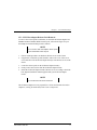
1
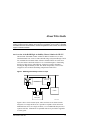
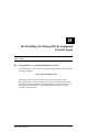
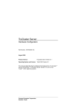
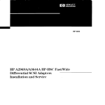
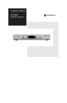
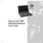
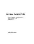
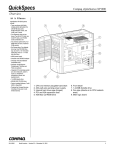
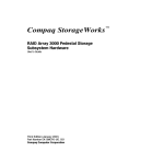
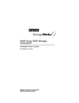
RA7000 / ESA10000 High Availability Solution Kit for HP-UX Installation Guide EK–HAHPU–MH. B01 Digital Equipment Corporation Maynard, Massachusetts 1st Edition, July 1998 The disclosure of this information does not grant the user a license under any patents, pending patents, trademarks, or copyrights or other rights of Digital Equipment Corporation, or of any third party. This software is proprietary to and embodies the confidential technology of Digital Equipment Corporation. Possession, use or copying of the software described in this publication is authorized only pursuant to a valid written license from Digital Equipment Corporation or an authorized sublicensor. Digital Equipment Corporation makes no representation that the use of its products in the manner described in this publication will not infringe on existing or future patent rights, nor do the descriptions contained in this publication imply the granting of licenses to make, use, or sell equipment or software in accordance with the description. UNIX is a registered trademark in the United States and other countries, licensed exclusively through X/Open Company, Ltd. Hewlett Packard and MC/ServiceGuard are registered trademarks of Hewlett Packard Corporation. The following are trademarks of Digital Equipment Corporation: DEC, RAID Array 7000 (RA7000), Enterprise Storage Array 10000 (ESA10000), HSZ70, StorageWorks, and the DIGITAL Logo. © Digital Equipment Corporation, 1998. Printed in U.S.A. All Rights Reserved Contents Revision Record About This Guide An Overview of the RAID High Availability Cluster Solution for HP-UX .........................vii Defining a “Clustered Host Server” ................................................................................. viii Audience ......................................................................................................................... viii Document Structure ......................................................................................................... viii Associated Documents.........................................................................................................x Conventions........................................................................................................................xi Support and Services ..........................................................................................................xi DIGITAL StorageWorks Web Site Address .......................................................................xii Getting Started RA7000 / ESA10000 (HA) Cluster Solution for HP-UX ROADMAP............................... xiii 1 Pre-Installation Steps 1.1 Verify (RA7000/ESA10000 for HP-UX) Cluster Requirements .............................. 1–1 1.2 Inventory the RAID SCSI Connection Kit............................................................... 1–2 1.3 Perform a System Backup....................................................................................... 1–4 1.4 Plan the Cluster Layout (SCSI Bus Interconnect) ................................................... 1–4 1.5 Prepare the SCSI Host Adapters.............................................................................. 1–6 1.5.1 Set Unique SCSI Host Adapter IDs................................................................... 1–6 1.5.2 SCSI Host Adapter Resistor Pack Removal (for mid-bus or end-bus RAID cluster layouts only)..................................................................................................... 1–7 2 Cabling the RAID Subsystem Cluster Components 2.1 Connecting RAID Subsystem Components through the SCSI Bus........................... 2–1 2.2 Mid-Bus RAID Cluster Layout - (SCSI Bus Interconnect) ..................................... 2–2 2.3 HUB-Radiant RAID Cluster Layout - (SCSI Bus Interconnect)............................... 2–3 2.4 End-Bus RAID Cluster Layout - (SCSI Bus Interconnect)....................................... 2–4 EK–HAHPU–MH. B01 iii RA7000 / ESA10000 High Availability Solution Kit for HP-UX 3 Software Setup Requirements for a Cluster 3.1 Software Requirements Summary ........................................................................... 3–1 3.2 Installing the StorageWorks CC RAID Manager Software ...................................... 3–1 3.3 Creating the RAID Storageset Configuration .......................................................... 3–2 3.4 Installing and Configuring MC/ServiceGuard Cluster Software .............................. 3–2 3.5 Running the SWCC Failover Transition Module Installation Script ........................ 3–3 A Cabling and Termination Required to Expand a Cluster A.1 Hardware Configuration of an Expanded Cluster ................................................... A–1 A.1.1 Adding Host Servers to an Existing Cluster ..................................................... A–2 A.1.2 Adding a Second RAID Subsystem to an Existing Cluster ............................... A–4 B De-Installing the StorageWorks Command Console Agent B.1 StorageWorks CC Agent De-Installation Procedures.............................................. B–1 Figures 1 RAID High Availability Cluster Concept ..................................................................vii 1–1 SCSI Host Adapter Model A28696A....................................................................... 1–8 1–2 SCSI Host Adapter Model A2969A ........................................................................ 1–8 1–3 SCSI Host Adapter Model A4107A ........................................................................ 1–9 2–1 Mid-Bus RAID Cluster Layout (SCSI Bus Interconnect)......................................... 2–2 2–2 Hub-Radiant RAID Cluster Layout (SCSI Bus Interconnect) .................................. 2–3 2–3 End-Bus RAID Cluster Layout (SCSI Bus Interconnect)......................................... 2–4 A–1 Expanded Cluster................................................................................................... A–2 A–2 Adding Host Servers to an Existing Cluster ........................................................... A–3 Tables 1 Associated StorageWorks and HP Documents.............................................................x 2 Style Conventions......................................................................................................xi 1–1 RAID RA7000 / ESA10000 for HP-UX - Cluster Prerequisites ............................... 1–1 1–2 RAID SCSI Connection Kit Contents (by kit number) ........................................... 1–3 1–3 RAID Subsystem Basic Cluster (SCSI Bus) Layout Options ................................... 1–5 iv EK–HAHPU–MH. B01 Revision Record This Revision Record provides a concise publication history of this manual. It lists the manual revision levels, release dates, and reasons for the revisions. The following revision history lists all revisions of this publication and their effective dates. The publication part number is included in the Revision Level column, with the last entry denoting the latest revision. This publication supports the StorageWorks RA7000 / ESA10000 Subsystem configured with or without a SCSI hub interconnect to two Hewlett Packard host servers running the HP-UX (Version 10.20 or later) operating system. The SCSI host adapters supported are HP models A28696A, A2969A and A4107A (all High Density 68-Pin compatible). Hewlett Packard MC/ServiceGuard (Version 10.10 or later) is the cluster software supported by this publication. Revision Level Date Summary of Changes EK–HAHPU–MH. A01 EK–HAHPU–MH. B01 July 1998 September 1998 Original release. Second release. EK–HAHPU–MH. B01 v About This Guide This section provides an overview of a StorageWorks RAID high availability (HA) cluster storage environment and defines the scope and conventions of this guide. It identifies associated reference documentation, and the StorageWorks sales, service, and technical support contacts worldwide. An Overview of the RAID High Availability Cluster Solution for HP-UX The RA7000 / ESA10000 Cluster solution for HP-UX enables two (or more) Hewlett Packard host servers to share a RAID storage subsystem through a SCSI bus, with MC/ServiceGuard cluster software. Should a failure on a host server occur, the failure is detected and the I/O is re-routed through to a functioning host server. This process, called failover, requires no resource downtime ensuring the high availability of data. The failed component(s) can be warmswapped or serviced while functioning components remain active. Figure 1 RAID High Availability Cluster Concept H ea rtb ea t 1 S erve r A A S erve r B H ea rtb ea t 2 A C lie nts R A ID S ub syste m S H R -1 02 4 - Figure 1 shows a basic cluster layout, where two host servers share a RAID subsystem via a single SCSI bus. It is possible to expand a cluster to include additional host servers on a single SCSI bus, or a second RAID subsystem on a separate SCSI bus. Illustrations of expanded clusters are provided in Appendix A of this guide. EK–HAHPU–MH. B01 vii RA7000 / ESA10000 High Availability Solution Kit for HP-UX Defining a “Clustered Host Server” For the host servers to be considered part of “the cluster” (e.g., share the RAID subsystem(s) and possess I/O failover capabilities), each server must be configured with MC/ServiceGuard cluster software, (including a “package” to failover the RAID CC agent), and the SCSI pass through device drivers that enable the SWCC agent to communicate with the RAID subsystem(s). This guide provides a master procedural roadmap to establish a “basic” cluster of shared RAID storage, focusing on cluster hardware and software configuration tasks. It begins with a new, boxed RAID subsystem and two HP host servers. Procedures for expanding a cluster are also discussed. Audience This guide is intended for experienced administrators and system integrators of HP host server and StorageWorks RA7000 / ESA10000 storage subsystem equipment. Setting up a cluster requires a general understanding of HP server networks, RAID storage concepts, HP MC/ServiceGuard cluster software and SCSI hardware configurations. Or, contact your service representative for installation assistance. Document Structure This guide contains the following chapters: Getting Started This section provides a roadmap to serve as the master procedural guide for establishing a cluster. Chapter 1: Pre-Installation Steps This chapter addresses the preparation needed before installing the hardware components of the RAID subsystem cluster. It provides a guide to your options in planning the cluster layout (e.g., the shared RAID subsystem, host servers and, if applicable, the SCSI hub), through the SCSI bus. This chapter also describes how to prepare the two SCSI host adapter boards for a cluster environment. viii EK–HAHPU–MH. B01 About This Guide Chapter 2: Cabling the RAID Subsystem Cluster Components This chapter describes the procedures for cabling a RAID subsystem to two HP host servers based on the cluster (SCSI) layout option selected in Chapter 1 of this guide. (Reference Appendix A if clustering more than two hosts or more than one RAID subsystem). It provides detailed illustrations of the cabling and termination required to support HD68-pin SCSI host adapter compatibility, and the use of a SCSI hub. Chapter 3: Software Setup Requirements for a Cluster This chapter summarizes and describes, in sequence, each of the software setups required to establish a cluster environment between multiple HP-UX host servers and a shared RAID storage subsystem. It explains how to access, invoke and interact with the SWCC Failover Transition Module Installation Script, which automatically configures the cluster for the seamless failover of the StorageWorks Command Console RAID Manager agent in the event of a server shutdown. Appendix A: Cabling and Termination Required to Expand a Cluster An expanded cluster is one in which more than two host servers are connected to a RAID subsystem on the same SCSI bus, or where a second RAID subsystem is added to the cluster on a separate SCSI bus. Appendix A provides the hardware cabling and termination, and highlights the software configurations required to expand a cluster. Appendix B: De-Installing the SWCC Failover Transition Module This appendix describes how to reverse the installation of the StorageWorks Command Console Failover Transition Module (agent) within a cluster. EK–HAHPU–MH. B01 ix RA7000 / ESA10000 High Availability Solution Kit for HP-UX Associated Documents In addition to this guide, the following documentation is useful to the reader: Table 1 Associated StorageWorks and MC/ServiceGuard Documents DIGITAL StorageWorks Document Title Order Number Getting Started - HSZ70 Solutions Software V7.1 for HP-UX Release Notes - RAID Array 7000 / Enterprise Storage Array 10000 for HP-UX AA-R84KB-TE AA-R84LA-TE RA7000 and ESA10000 Storage Subsystem User’s Guide EK-SMCPP-UG Configuring Your StorageWorks Subsystem HSZ70 Array Controllers Version 7.0 EK-HSZ70-CG Servicing Your StorageWorks Subsystem HSZ70 Array Controllers HSOF Version 7.0 EK- HSZ70-SV 16-Bit SCSI Bus Hub (DWXXH) SWCC Command Console 2.0 User’s Guide CLI Reference Manual HSZ70 Array Controllers HSOF Version 7.0 EK-DWZZH-UG AA-R60EA-TE EK-CLI70–RM HP MC/ServiceGuard Document Title HP A2969A HP-HSC Fast/Wide Differential SCSI Adapter Installation and Service guide A2969-90001 HP-PB Fast/Wide High-Performance SCSI Adapter Installation and Service guide (for host adapter 28696) 28696-90001 HP A4107A SCSI Adapter Installation and Service guide A4107-90001 Hands-On with High Availability and MC/ServiceGuard Student Workbook (Version A.02) Managing MC/ServiceGuard H6487 B3936-90019 To Order HEWLETT PACKARD products To order Hewlett Packard MC/ServiceGuard cluster software/documentation, contact your local sales representative, or contact the HP Customer Support hotline at: US Customers: 1-800-633-3600 Hewlett Packard Customer Support can also be reached through electronic mail at: http://www.hp.com x EK–HAHPU–MH. B01 About This Guide Conventions In this guide, references to StorageWorks RAID Array, controller, HSZ70 or subsystem pertain to • RAID Array 7000 (RA7000) or Enterprise Storage Array (ESA) 10000 The term High Availability is abbreviated as (HA). This guide uses the following documentation conventions: Table 2 Style Conventions Style Meaning boldface monospace type italic type To be input by the user. For emphasis, manual titles, utilities, menus, screens, and filenames. Screen text. Represents the HP system prompt. Do not type it as part of information to be input by the user. plain monospace type # StorageWorks Support and Services Who to contact in the Americas Local Sales Office / StorageWorks Hotline 1-800-786-7967 Contact the DIGITAL Distributor where the Installation Support: Storage Solution was Purchased / Local DIGITAL Sales Office. DIGITAL Multivendor Customer Service (MCS) Contact the DIGITAL Customer Support Installation Center (CSC). Contact the DIGITAL Customer Support Warranty Center (CSC) for warranty service after s olution is installed and operating. Information and Product Questions: Remedial Customer Support Center (CSC) EK–HAHPU–MH. B01 Contact the DIGITAL Customer Support Center (CSC). Note: A Service Contract is recommended when the equipment is out of warranty. Contact the local DIGITAL Sales Office. 1- 800-354-9000 xi RA7000 / ESA10000 High Availability Solution Kit for HP-UX Who to contact in Europe Information and Product Questions, Installation Support, and Installation: For Warranty Service For Remedial Service Contact the DIGITAL Distributor or reseller from whom the Storage Solution was purchased. See the Warranty Card packaged with the product. Contact the DIGITAL Distributor or reseller from whom the Storage Solution was purchased. Note: A Service Contract is recommended when the equipment is out of warranty. Who to contact in Asia Pacific For all services, contact the DIGITAL Distributor or reseller from whom the equipment was purchased. Visit our Web Site for the Latest Information The latest StorageWorks documentation and technical tips can be found at: http://www.storage.digital.com xii EK–HAHPU–MH. B01 Getting Started This section contains a roadmap to serve as your master guide for establishing a high availability cluster between two or more HP-UX host servers and a shared RAID subsystem. This roadmap presides over all other documentation supplied with your equipment, and refers to those resources as more technical depth is required. RA7000 / ESA10000 (HA) Cluster Solution for HP-UX - - - - - - - - - - - RoadMap - - - - - - - - - - STEP PERFORM THIS PROCEDURE… DESCRIBED IN… 1 All Pre-Installation steps, Including… ◊ Verify Cluster Requirements ◊ Verify SCSI Connection Kit Contents ◊ Perform a System Backup ◊ Plan the Cluster (SCSI bus) Layout ◊ Prepare the SCSI Host Adapters RA7000 / ESA10000 Cluster Solutions for HP-UX - Chapter 1 2 Unpack and Setup the RAID Subsystem Getting Started HSZ70 Solutions Software V7.1 for HP-UX – Chapter 1 or 2 3 Cable and Terminate the Cluster Components RA7000 / ESA10000 Cluster Solutions for HP-UX – Chapter 2 4 Install the StorageWorks Command Console (CC) RAID Manager Software Getting Started HSZ70 Solutions Software V7.1 for HP-UX – Chapter 4 5 Create the RAID Storage Configuration Getting Started HSZ70 Solutions Software V7.1 for HP-UX – Chapter 6 or 7 and Appendix B 6 Install/Configure HP MC/ServiceGuard on all Clustered Host Servers (HP) Managing MC/ServiceGuard manual 7 Run the SWCC Failover Transition Module Installation Script RA7000 / ESA10000 Cluster Solutions for HP-UX – Chapter 3 8 Test, Monitor and Manage the Cluster (HP) Managing MC/ServiceGuard manual EK–HAHPU–MH. B01 xiii 1 Pre-Installation Steps This chapter addresses the preparation needed before installing and configuring the RA7000 / ESA10000 cluster hardware components. The pre-installation steps required to support a cluster are as follows: • • • • • 1.1 Verify Cluster Requirements Inventory the SCSI Connection Kit Perform a System Backup Plan the Cluster Layout (e.g., the SCSI Bus Interconnect) Prepare the SCSI Host Adapters Verify (RAID RA7000/ESA10000 for HP-UX) Cluster Requirements Please verify that the cluster requirements listed in Table 1-1 are met. Table 1–1 RAID RA7000 / ESA10000 for HP-UX – Cluster Prerequisites Host Feature Requirement Platform Two (minimum) HP host servers Operating System HP-UX version 10.20 or later Cluster Software HP MC/ServiceGuard version 10.10 or later Free Disk Space 500KB per server for MC/ServiceGuard software Storage Subsystem StorageWorks RA7000 or ESA10000 RAID subsystem RAID Controllers Two StorageWorks HSZ70 controllers per RAID subsystem, trilinked, operating firmware V7.0 SCSI Host Adapters HP, HD68-pin (one adapter per host server). Supported models: A28696A, A2969A, A4107A. Additional Items Requirement RAID SCSI Connection Kit (Reference Table 1-2 for contents) RAID Hardware RAID subsystem kit DS-SWXRA-xx Service Tools Appropriate tools to service your equipment Technical Documentation The reference guides for the RAID subsystem, HP servers and MC/ServiceGuard cluster software supplement this installation guide. EK–HAHPU–MH. B01 1–1 RA7000 / ESA10000 High Availability Solution Kit for HP-UX NOTES 1.2 1. All of the host features that are supported by the platform kit are also supported in the RAID/HP cluster environment 2. The installation of a hub requires a 3.5” SSB slot available in your StorageWorks pedestal or shelf. Inventory the RAID SCSI Connection Kit Three types of RAID SCSI Connection Kits exist. Each kit supports the connection of two host servers to a RAID subsystem via a single SCSI bus. To connect more than two host servers in a cluster, or to add a second RAID subsystem, additional parts must be ordered (Reference Appendix A for parts required to expand a cluster). The part numbers and purpose served by each kit is as follows: • SWXKT-DE – for connecting the RAID subsystem to servers having HD68-pin host adapters • SWXKT-DF* – for connecting the RAID subsystem to servers having VHDCI (UltraSCSI) host adapters • SWXKT-EA – for connecting the RAID subsystem through a hub to servers having either HD68-pin or VHDCI host adapters (both adapters must be the same type) *This kit is not applicable to a RAID RA7000 / ESA10000 Cluster for HP-UX Please verify that the connection kit you have received is specific to your cluster needs, and use Table 1-2 to inventory its contents. If you are missing any hardware component required for a cluster, please contact your local sales representative or call the StorageWorks Hotline at 1-800-STORWORK (7867967). 1–2 EK–HAHPU–MH. B01 Chapter 1. Pre-Installation Steps Table 1–2 RAID SCSI Connection Kit Contents (listed by kit number) R AID S CS I Connection Kit Parts Identification K it S W X KT-DE K it Kit S W X K T-EA SW X K T-D F B N 2 1K-0 5 1 H D 6 8 S tr a ig h t-T h ru C a b le B N 3 7A-0 5 2 1 1 1 2 1 V H D C I (U ltra S C S I) S tra ig h t-T h r u C ab le B N 3 8C -0 5 1 V H D C I-to -H D 6 8 A d a p ter C a b le (5 m e te r) B N 3 8E-0 B V H D C I-to - H D 6 8 A d a p te r C a b le B N 2 1W -0B H D 6 8 -P in Y - C a b le 2 B N 3 7C -0 C 2 V H D C I Y -C a b le H 87 9-A A H D 6 8 M D iffe re n tia l Te rm in a to r 2 H 88 63 -A A 2 V H D C I M D iffe re n tia l Te rm in a to r D S-D W Z Z H -03 1 3 -P o rt D iffe re n tia l H u b S H R -1 0 2 6 NOTES 1. Above, VHDCI (UltraSCSI) parts are shaded; HD68-Pin (fast, wide SCSI) are white. 2. To supplement the RAID SCSI Connections Kit, please locate the following parts supplied with your RAID subsystem: • One BN37A-05 - VHDCI UltraSCSI (straight-thru) cable (RA7000) • One BN38E-0B - VHDCI-to-HD68-Pin Adapter cable (RA7000 / ESA1000) EK–HAHPU–MH. B01 1–3 RA7000 / ESA10000 High Availability Solution Kit for HP-UX 1.3 Perform a System Backup Follow normal procedures to backup the RAID subsystem and the host servers in your cluster, as applicable, prior to installing any of the cluster components. 1.4 Plan the Basic Cluster Layout (SCSI Bus Interconnect) To plan the layout of cluster components through the SCSI bus, first define the two ends of the SCSI bus by selecting where you want to locate the RAID subsystem on the bus relative to the other components (the two HP hosts and, if applicable, the SCSI Hub). Determining the RAID location depends on your preference or any physical limitations of your facility (see “Note” below). You can locate the RAID subsystem: • In the middle of the SCSI bus - (Mid-Bus RAID) • Radiating from a Hub - (Hub-Radiant RAID) • On an end of the SCSI bus - (End-Bus RAID) NOTE The maximum bus length for a mid-bus or an endbus RAID layout is 25M (include the Y-cable length when calculating total bus length). For a hub-radiant RAID layout, the maximum distance of each radial arm (from the hub to a device) is 25M. 1–4 EK–HAHPU–MH. B01 Chapter 1. Pre-Installation Steps Table 1–3 RAID Subsystem Basic Cluster (SCSI Bus) Layout Options For This Cluster Layout Option Mid-Bus RAID H o st A And This Type of Host Adapter HD68-Pin Reference This Section & Figure 2.2 2–1 R A 7 0 0 0 / E S A 1 00 0 0 H o st B S u bs y s te m SHR-1021 For This Cluster Layout Option… Hub-Radiant RAID Mid-Bus RAID And This Type of Host Adapter… HD68-Pin Reference This… Section & Figure 2.3 2–2 Host B H o st A HUB R A7000 / E S A10000 S ub s y s te m SHR-1023 Hub-Radiant RAID For This Cluster Layout Option … And This Type of Host Adapter… End-Bus RAID HD68-Pin H o st A H o st B R A 7 0 0 0 / E S A 1 0 00 0 S u b sy ste m SHR-1022 EK–HAHPU–MH. B01 Reference This… Section & Figure 2.4 2–3 End-Bus RAID 1–5 RA7000 / ESA10000 High Availability Solution Kit for HP-UX Use Table 1-3 to select the basic cluster layout that best suits your environment. Prepare and install the SCSI host adapters into your servers (as described in Section 1.5, “Prepare the SCSI Host Adapters”). Then, reference Chapter 2, – Cabling the RAID Subsystem Cluster Components, to proceed with the basic cluster installation. 1.5 Prepare the SCSI Host Adapters Each of the host servers in the RAID subsystem cluster requires at least one supported SCSI host adapter be installed. (Expanding a cluster with a second RAID subsystem requires two SCSI host adapters per server). Prior to installing the SCSI host adapter(s) into each server, as described in your HP Host Adapter installation and service guide, you must prepare each one for a cluster environment. This involves two main steps: • Setting a unique SCSI host adapter ID • (For Mid-Bus RAID and End-Bus RAID cluster layouts only) Removing the resistor packs (terminators) on-board the SCSI host adapter The procedures for setting unique SCSI host adapter IDs and removing resistor packs from the SCSI host adapters are contained in the following sections. As you perform these steps, reference the figure that corresponds to your SCSI host adapter model, as follows: SCSI Host Adapter Illustrated In A28696A Figure 1-1 A2969A Figure 1-2 A4107A Figure 1-3 1.5.1 Set Unique SCSI Host Adapter IDs It is mandatory that each server in a cluster have a unique SCSI host adapter ID (target ID). The default setting of a SCSI host adapter ID is 7. One of the hosts in the cluster can maintain this ID. Typically, the SCSI IDs for each added server should decrease one number from 7, (6, 5, 4, etc.), to ensure that an unused device number is selected for the server ID. Use the dip switch on-board the SCSI host adapter(s) to manually set the SCSI host adapter ID on each host server in the cluster to an unused number. (Two host adapters in the same server can have the same SCSI ID, as long as the adapters are not on the same SCSI bus). Reference the Figure for your SCSI host adapter model to locate the SCSI ID dip switch pack. 1–6 EK–HAHPU–MH. B01 Chapter 1. Pre-Installation Steps 1.5.2 SCSI Host Adapter Resistor Pack Removal To remove the resistor packs (terminators) on-board the SCSI host adapters in a Mid-Bus RAID or End-Bus RAID cluster layout, reference the figure for your host adapter board model and proceed as follows: NOTE Do not remove SCSI host adapter resistor packs in hub-radiant RAID cluster layouts. 1. Follow normal procedures to shutdown all host servers in the cluster. 2. If applicable, consult the system manual to remove the cover of the server cases and remove the SCSI host adapter board(s) from all host servers in the cluster. 3. Locate the resistor packs on the SCSI host adapter board(s) 4. Gently remove the resistors from the SCSI host adapter boards 5. Install the SCSI host adapter board(s) into the servers according to the SCSI host adapter installation manual supplied with your SCSI host adapter model. NOTE Do not reboot the host servers at this time. The SCSI host adapters are now prepared for a cluster environment. Proceed to Chapter 2, Cabling the RAID Subsystem Cluster Components. EK–HAHPU–MH. B01 1–7 RA7000 / ESA10000 High Availability Solution Kit for HP-UX Figure 1–1 SCSI Host Adapter Model A28696A F acep la te Te rm in ation R e sistor P acks R 13 , R 1 4 , R 1 5 S C S I A da pte r ID S w itch P a ck "S 1 " S H R -11 2 2 Figure 1–2 SCSI Host Adapter Model A2969A Te rm in ato r R esisto r P a cks R 23 , R 2 4, R 2 5 Fa cep la te S C S I A da pter ID S w itch P ack "SW 1 " S H R -11 2 1 1–8 EK–HAHPU–MH. B01 Chapter 1. Pre-Installation Steps Figure 1–3 SCSI Host Adapter Model A4107A Term ina tio n R esisto r P a cks U C 1 , U C 2 , U C 3 S C S I A d ap te r ID S w itch P acks "S 1" Fa ce plate S H R -11 2 3 EK–HAHPU–MH. B01 1–9 2 Cabling the RAID Subsystem Cluster Components This chapter provides the procedures for interconnecting two HP host servers and a shared StorageWorks RAID subsystem through the SCSI bus, and externally terminating the bus as applicable. Interconnection procedures for locating the RAID subsystem in a Mid-Bus, Hub-Radiant and End-Bus layout are provided, based upon the basic cluster layout selected in Chapter 1. 2.1 Connecting RAID Subsystem Components through the SCSI Bus Based on the basic RAID cluster (SCSI bus) layout option you have selected, locate the procedures in this section (cross-referenced in Chapter 1, Table 1-1 of this guide), to cable and terminate the cluster components through the SCSI bus. When you have finished, reboot all the servers in the cluster. NOTES • The following procedures assume that the SCSI host adapters have been prepared (e.g., onboard resistor packs removed and SCSI IDs set) as described in Chapter 1. • For clarity in Figures 2-1 through 2-3, the VHDCI SCSI cables and terminators are shaded and the HD68-pin (fast, wide SCSI) components are white. • Cables and terminators supplied with your RAID subsystem supplement the components in your RAID SCSI Connection Kit. (See Chapter 1, Table 1-2 ). EK–HAHPU–MH. B01 2–1 RA7000 / ESA10000 High Availability Solution Kit for HP-UX 2.2 Mid-Bus RAID Cluster Layout - (SCSI Bus Interconnect) To connect two HP hosts on the two ends of the SCSI bus (e.g., a Mid-Bus RAID cluster layout), with a RAID subsystem, reference Figure 2-1 and follow these steps: 1. Attach a Y-cable (BN21W-0B) to the HD68-pin host adapter on Host A. 2. Attach a Y-cable (BN21W-0B) to the HD68-pin host adapter on Host B. 3. Attach (compatible) end of a 5M adapter cable (BN38C-05) to one end of the Y-cable attached to Host A. 4. Connect the other end (VHDCI compatible) of the adapter cable to the end of a tri-link connector on a subsystem controller. 5. Attach (compatible) end of the short adapter cable (BN38E-0B) to one end of the Y-cable attached to Host B. 6. Connect the other end (VHDCI-compatible) of the adapter cable to the end of UltraSCSI cable BN37A-05. 7. Remove the terminator that occupies the tri-link connector on the subsystem controller. 8. Attach the remaining end of the VHDCI UltraSCSI cable attached to Host A to the available tri-link connector on the subsystem controller. 9. Connect a terminator (H879-AA) to the available end of the Y-cable on Host A, and to the available end of the Y-cable on Host B. Figure 2–1 Mid-Bus RAID Cluster Layout - (SCSI Bus Interconnect) HOST A R A 70 00 or E S A 10000 S ubsystem H D68 H ost A da pter B N 21W -0B Y -Ca ble Te rm inato r H 87 9-A A H O ST B H D 68 H os t A dapter B N 37A -0E Tri-L ink B N3 8C -05 V H D CI-to-H D 68 A dapter C ab le B N 2 1W -0B Y -Ca ble B N37A -05 V H DC I-to-V HD C I U ltraS C S I C able B N 38E -0B V H D C I-to-H D 68 A da pter Ca ble Term inato r H 879-A A S H R - 1 0 92 2–2 EK–HAHPU–MH. B01 Chapter 2. Cabling the RAID Subsystem Cluster Components 2.3 HUB-Radiant RAID Cluster Layout - (SCSI Interconnect) To connect two HP host servers to a RAID subsystem via use of a Hub (e.g., a Hub-Radiant RAID cluster layout), reference Figure 2-2 and follow these steps: 1. Attach (compatible) end of the 5M adapter cable (BN38C-05) to the HD68pin host adapter on Host A. 2. Connect the other end of the adapter cable to a convenient hub port. 3. Attach the compatible end of the short adapter cable (BN38E-0B) to the HD68-pin host adapter on Host B. 4. Connect the other end of the short adapter cable to the end of an UltraSCSI cable (BN37A-05). 5. Attach the remaining end of the UltraSCSI cable to a convenient hub port. 6. Connect one end of an UltraSCSI cable (BN37A-05) to a subsystem controller. 7. Attach the other end of the UltraSCSI cable to the remaining hub port. 8. Connect a terminator (H8863-AA) to the remaining tri-link connector on the subsystem controller. Figure 2–2 Hub-Radiant RAID Cluster Layout - (SCSI Bus Interconnect) HOST A H D 68 H os t A da p ter HO ST B D S-DW ZZH-03 U ltraSCSI H UB (3-Port, VHD CI) H D 6 8 H os t A da pter B N 38 E -0B V H D C I-to-H D 6 8 A da pte r C a ble B N 3 8 C -05 V H D C I-to-H D 6 8 A da pter C ab le B N 37 A -05 V H D C I-to -V H D C I U ltraS C S I C a b le B N 37A -0E Tr i-L in k RA7000 or ESA10000 Subsystem B N 3 7A -0 5 Te rm inato r H 8 8 63-A A S HR -1 09 3 NOTE: In hub configurations, termination is internal to the hub. EK–HAHPU–MH. B01 2–3 RA7000 / ESA10000 High Availability Solution Kit for HP-UX 2.4 End-Bus RAID Cluster Layout - (SCSI Bus Interconnect) To connect two HP host servers to a RAID subsystem located on the end of the SCSI bus (e.g., an End-Bus RAID cluster layout), reference Figure 2-3 and follow these steps: 1. Attach a Y-cable (BN21W-0B) to the HD68-pin host adapter on Host A. 2. Attach a Y-cable (BN21W-0B) to the HD68-pin host adapter on Host B. 3. Attach one end of the HD68-pin straight-thru cable (BN21K-05) to a convenient end of the Y-cable attached to Host A. 4. Connect the other end of the cable to a convenient end of the Y-cable attached to Host B. 5. Attach the compatible end of the 5M adapter cable (BN38C-05) to the available end of the HD68-pin Y-cable attached to Host B. 6. Connect the other (VHDCI-compatible) end of the adapter cable to the available end of a tri-link connector on a subsystem controller. 7. Connect terminator H8863-AA to the available end of a tri-link connector on a subsystem controller. 8. Connect terminator H879-AA to the available end of the Y-cable attached to Host A. Figure 2–3 End-Bus RAID Cluster Layout - (SCSI Bus Interconnect) H OST A HOST B H D 68 H os t A dapte r B N 21W -0B Y -C ab le Term ina tor H 8 79-A A 2–4 R A 7000 or E S A 1000 0 Su bsystem HD 68 Ho st A d ap te r B N 21W -0B Y -C ab le B N2 1K -05 H D68 S traight-Thru B N 37 A -0E Tri-Link B N38C -0 5 V HD C I-to-H D 68 A dapter C able Term inator H8863-A A S H R -1 0 9 4 EK–HAHPU–MH. B01 3 Software Setup Requirements for a Cluster This chapter summarizes and describes in sequence each of the software setups required to establish a high availability cluster environment between multiple HP-UX host servers and a shared RAID storage subsystem. 3.1 Software Requirements Summary The software setups required to establish a cluster between your RAID subsystem and HP host servers must be performed in the sequence provided in this chapter, which is as follows: 3.2 • Install the StorageWorks Command Console (SWCC) RAID Manager software • Create the RAID storageset configuration • Install and configure MC/ServiceGuard cluster software on all clustered host servers • Install/configure the (HP) SCSI pass through device driver software on all remaining host servers comprising the RAID subsystem cluster. • Run the SWCC Failover Transition Module Installation Script Installing the StorageWorks CC RAID Manager Software The StorageWorks Command Console agent software, which enables management of the RAID subsystem, must be installed and configured on any host server in the cluster from which you choose to perform the initial cluster configuration work. This server is designated as the “primary” host, and all other servers in the cluster, “secondary”. This designation must remain constant throughout the procedures described in this chapter. Reference the Getting Started – HSZ70 Solutions Software V7.1 for HP-UX, Chapters 3 and 4, for procedures to install the StorageWorks CC RAID Manager Software on your primary host server. (Chapter 3 is required to prepare your primary host server with the SPT device driver that facilitates communication with the RAID subsystem, and for configuring the HP-UX file system). EK–HAHPU–MH. B01 3–1 RA7000 / ESA10000 High Availability Solution Kit for HP-UX 3.3 Creating the RAID StorageSet Configuration Reference the Getting Started – HSZ70 Solutions Software V7.1 for HP-UX, Chapters 6 or 7 and Appendices A and B, to plan and create your RAID (storageset) configuration. 3.4 Installing and Configuring HP MC/ServiceGuard Cluster Software HP MC/ServiceGuard cluster software must be installed and configured on all host servers that share the RAID subsystem. CAUTION If a server is connected to a cluster, but is not configured with MC/ServiceGuard software, undesirable conditions could result. Reference the (HP) Managing MC/ServiceGuard manual to install and configure MC/ServiceGuard cluster software on all (primary and secondary) HP host servers that comprise your cluster. NOTES When you are using MC/ServiceGuard and assigning the MAX_CONFIGURED_PACKAGES, allow an extra package assignment for the SWCC agent. For a cluster containing more than two servers, The \.rhosts file must contain the “hostname root” or “IPaddress root” of all servers in the MC/ServiceGuard cluster, not just the two servers connected to the RAID subsystem. 3–2 EK–HAHPU–MH. B01 Chapter 3. Software Setup Requirements for a Cluster 3.5 Running the SWCC Failover Transition Module Installation Script The SWCC Failover Transition Module Installation Script automates the final software configuration tasks required to establish failover of the StorageWorks Command Console agent, which are: • Install the (HP) SCSI pass through device drivers on all the remaining clustered servers. (These drivers should already reside on your primary host, via the SWCC agent installation process performed in Section 3.2). WARNING Installing the SCSI pass through drivers requires a reboot of all servers on which it will be installed. • Install the SWCC Failover Transition Module (agent) in an MC/ServiceGuard “package” on all clustered servers. In order for the SWCC RAID Manager agent to failover in the case of a server shutdown, it must be installed in a “package” in the MC/ServiceGuard software that resides on each host server. A copy of the package resides on all hosts. Under normal operating conditions, the RAID Manager will run on the primary host only. When the primary host is unavailable as in a failover, MC/ServiceGuard will start up the RAID Manager on a secondary, assigned takeover host. To obtain and invoke the SWCC Failover Transition Module Installation Script required for your MC/ServiceGuard cluster configuration, proceed as follows: 1. Download a copy of the tar file (ha_stm_hp01.tar) into your /tmp directory, from the following StorageWorks website address: http://www.storage.digital.com/menusupport.htm 2. Set your current directory to /tmp 3. Extract the script software from the downloaded files by issuing this command: # tar xvf /tmp/ha_stm_hp01.tar EK–HAHPU–MH. B01 3–3 RA7000 / ESA10000 High Availability Solution Kit for HP-UX NOTES You MUST be root to proceed with the installation process. The capital letter at the end of each script prompt represents the default response. 4. Run the shell script by issuing this command: # /tmp/ha_install_hp.sh The SWCC Failover Transition Module Installation Script will prompt you to make several selections regarding your specific cluster configuration options. For the seamless failover of the SWCC transition module agent, be prepared to provide the script with the following information as prompted: • name of root directory to place the SWCC software • subnet address of the cluster • dedicated IP address for the SWCC failover agent (this is the IP address used by the SWCC client in order for you to configure and monitor the RAID subsystem within the cluster) The installation of the SWCC Failover Transition Module in your cluster is now complete. Reference your (HP) Managing MC/ServiceGuard manual for procedures to test server failover, and to monitor and manage your cluster. 3–4 EK–HAHPU–MH. B01 A Cabling and Termination Required to Expand a Cluster This appendix summarizes how to expand a basic (two-server, single RAID subsystem) cluster to support additional servers and/or a second RAID subsystem. This appendix assumes that the pre-installation, hardware and software configuration procedures for a basic cluster have been performed as described in this guide, and focuses only on the procedures required for cluster expansion. A.1 Hardware Configuration of an Expanded Cluster A basic cluster, (2 server, single RAID subsystem) configured in an End-Bus RAID or Mid-Bus RAID cluster layout, can be expanded in two ways: 1. By adding host servers to a single SCSI bus 2. By adding a second RAID subsystem via a separate SCSI bus Figure A-1 shows an expanded cluster, where one or more servers have been added the cluster by extending the SCSI bus of the basic cluster, and a second RAID subsystem has been added on a separate SCSI bus. Both RAID subsystems can be accessed by all clustered servers. The two heartbeats shown in Figure A-1 represent the failover capabilities configurable between clustered servers using MC/ServiceGuard software. In other words, all servers with MC/ServiceGuard software can be configured to failover any other server in the cluster that has MC/ServiceGuard software. The cabling and termination required to expand a cluster are discussed and illustrated in the following sections. EK–HAHPU–MH. B01 A–1 RA7000 / ESA10000 High Availability Solution Kit for HP-UX Figure A–1 Expanded Cluster N etw ork Incon n ect H ea rtb ea t 1 H ea rtb ea t 2 S erver A A C lien ts S erver C S erve r B A A A A A S C S I B us 1 Te rmination SC SI B u s 1 Te rmin ation S C SI B u s 2 Termin atio n S C S I B us 2 Term ina tion R a id S u bsyste m R aid S ub sys tem S H R -11 3 1 A.1.1 Adding Host Servers to an Existing Cluster Each host server added to a cluster requires the following cables: A–2 Part No. Description BN21K-xx HD68-Pin straight-thru BN21W-0B HD68-Pin Y-cable EK–HAHPU–MH. B01 Appendix A. Cabling and Termination Required to Expand a Cluster To add a host server to a basic End-Bus or Mid-Bus RAID subsystem cluster, reference Figure A-2 and proceed as follows: 1. Follow normal procedures to backup the all the devices in the existing cluster. 2. Follow normal procedures to power down all the devices in the existing cluster. 3. Attach a Y-cable (BN21W-0B) to the SCSI host adapter of the server being added to the cluster. 4. Connect cable BN21K-05 (HD68-pin straight-thru) to an end of the Y-cable just attached to your new server. 5. Remove the external terminator (H879AA) connected to the end of the Ycable of the last server on the SCSI bus in your existing cluster. 6. Attach the terminator just removed, to the remaining end of the Y-cable connected to your new server. 7. Connect one end of cable BN21K-05 (HD68-Pin straight-thru) to the end of the Y-cable of the server from which the terminator was removed. 8. Connect the other end of cable BN21K-05 to the available end of the Ycable of your new server. Figure A–2 Adding Host Servers to an Existing Cluster H ost S erver H o st S erve r H o st A da pte r H os t A da pte r B N 2 1W -0 8 H D 6 8 P in Y - C a b le B N 2 1W -0 8 H D 68 P in Y - C a b le C o n ne cts To N e x t S e rve r o r T he R a id S y s te m E nd O f B u s M u st B e Term in a ted (Term in a to r H 8 79 A A ) B N 21 K 0 5 (H D 6 8 P in S traig h t T hru ) S H R -112 8 EK–HAHPU–MH. B01 A–3 RA7000 / ESA10000 High Availability Solution Kit for HP-UX NOTES Repeat these procedures for each new server to be added to the cluster. When finished, follow normal procedures to power-up all cluster devices. Make sure that each server added to the cluster is configured for a cluster, according to Chapter 3 of this guide. A.1.2 Adding a Second RAID Subsystem to an Existing Cluster A second RAID subsystem can be added to an existing cluster by building a second, separate SCSI bus between the existing clustered servers and the new RAID subsystem. This requires a second SCSI host adapter be prepared and installed (reference Chapter 1, Pre-Installation Steps), in each of the host servers comprising the cluster. In this scenario, both RAID subsystems can be shared by all clustered servers. Figure A-1 illustrates the cluster layout when a second subsystem (and more than two servers) are added to a Mid-Bus RAID subsystem cluster layout. NOTES The second RAID subsystem must be configured as defined in the RoadMap of the Getting Started section of this guide. Follow normal procedures to backup the existing cluster devices and then power down the cluster devices prior to connecting the second subsystem. Reference Chapter 2, “Cabling the RAID Subsystem Components” for the parts and procedures required to cable and terminate a SCSI bus, integrating the following differences that apply to the second subsystem: A–4 1. Physically cable the second RAID subsystem to the same two host servers as the first (existing) RAID subsystem. 2. Connect the Y-cables to the second host adapter in each server. 3. Be sure to terminate both ends of the second SCSI bus. EK–HAHPU–MH. B01 B De-Installing the StorageWorks Command Console Agent This appendix describes how to reverse the installation of the StorageWorks CC Agent within a cluster. B.1 StorageWorks CC Agent De-Installation Procedures To de-install the CC agent (and the CC agent package) from the cluster, enter the following command: # /base_dir/steam/bin/stgwks.sh Select menu option 4 of the first menu. Then select menu option 5 of the subsequent menu. You will be prompted to exit to remove pass-through drivers, if installed, and then prompted to confirm the directory location. Answer yes to both prompts to remove the CC agent and the MC/ServiceGuard CC agent “package” from the cluster. EK–HAHPU–MH. B01 B–1 Reader’s Comments Manual Order Number: EK–HAHPU–MH. B01 DIGITAL is committed to providing the best products and services. Since our manuals are important components of our products, we value your comments, corrections, and suggestions for improvements. Please take a few minutes to fill out and return this form. Attach additional sheets, if necessary. Thank you. Excellent Manual Rating Accuracy (correct presentation of facts) [ ] Completeness (adequate information) [ ] Clarity (easy to understand) [ ] Organization (logical sequence of information) [ ] Layout (easy to follow subject matter) [ ] Indexing (easy to locate desired information) [ ] Good [ ] [ ] [ ] [ ] [ ] [ ] Fair [ ] [ ] [ ] [ ] [ ] [ ] Poor [ ] [ ] [ ] [ ] [ ] [ ] Errors Noted (include page, paragraph, table or figure number) ___________________ Most-Liked Features: ____________________________________________________ Least-Liked Feature _____________________________________________________ Suggestions for Improvement______________________________________________ Return Address: Digital Equipment Corporation Customer Research Response Center 334 South Street, SHR3-2/W3 Shrewsbury, MA 01545 Name Phone Title Company Street Address Mail Stop City Country (if other than USA) State ZIP