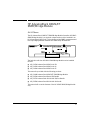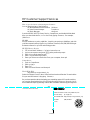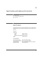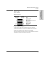
1
HP AdvanceStack 100VG/ET
SNMP/Bridge Module
Installation and Reference Guide
© Copyright 1996 Hewlett-Packard Company
All Rights Reserved.
This document contains information which is protected by
copyright. Reproduction, adaptation, or translation without
prior permission is prohibited, except as allowed under the
copyright laws.
Publication Number
J2414-90021
Edition 2
January 1996
Applicable Product
Disclaimer
The information contained in this document is subject to
change without notice.
HEWLETT-PACKARD COMPANY MAKES NO WARANTY
OF ANY KIND WITH REGARD TO THIS MATERIAL,
INCLUDING, BUT NOT LIMITED TO, THE IMPLIED
WARRANTIES OF MERCHANTABILITY AND FITNESS
FOR A PARTICULAR PURPOSE. Hewlett-Packard shall not
be liable for errors contained herein or for incidental or
consequential damages in connection with the furnishing,
performance, or use of this material.
Hewlett-Packard assumes no responsibility for the use or
reliability of its software on equipment that is not furnished
by Hewlett-Packard.
HP J2414B
Warranty
Trademark Credits
See the warranty card included with the product.
MS-DOS® and Microsoft® are U.S. registered trdemarks of
Microsoft Corporation. Ethernet is a registered trademark of
Xerox Corporation.
A copy of the specific warranty terms applicable to your
Hewlett-Packard product and replacement parts can be
obtained from your HP sales and service office or
HP-authorized reseller.
Hewlett-Packard Company
8000 Foothills Boulevard, m/s 5551
Roseville, California 95747-5551
http://www.hp.com/go/network_city
HP AdvanceStack 100VG/ET
SNMP/Bridge Module
At A Glance
The HP AdvanceStack 100VG/ET SNMP/Bridge Module (hereafter HP 100VG
SNMP/Bridge Module) is an optional component that can be installed in an
HP AdvanceStack 100VG hub. This module provides SNMP management and
two-way bridging between Ethernet and 100VG-AnyLAN networks.
The hubs into which an HP 100VG SNMP/Bridge Module can be installed
include:
■
HP J2413A AdvanceStack 100VG Hub-7M
■
HP J2415A AdvanceStack 100VG Hub-14
■
HP J2410A AdvanceStack 100VG Hub-15
This manual is provided with the following products:
■
HP J2414B AdvanceStack 100VG/ET SNMP/Bridge Module
■
HP J3159A AdvanceStack Router 210 Bundle
■
HP J3157A AdvanceStack Dial-A-LAN 2A/Plus Bundle
■
HP J3158A AdvanceStack Dial-A-LAN 4A Bundle
This manual will cover the features of the HP 100VG SNMP/Bridge Module
only.
iii
Features
If the optional HP 100VG SNMP/Bridge Module is installed in your hub, the
hub functionality is enhanced with these additional features:
■
SNMP agent code enabling the hub to be managed remotely from a
network management station that supports Simple Network Management
Protocol (SNMP) over IP or Novell NetWare (IPX).
■
ASCII console where you can diagnose and configure the hub through
a serial connection or by using Telnet.
■
10:100 and 100:10 bridge functionality for connecting the
HP 100VG LAN (or 100 Mbit/s network) to an Ethernet/IEEE 802.3 LAN
(or 10 Mbit/s network). The bridge supports up to 1,024 addresses (512
for 100VG and the other 512 for Ethernet). The HP J2414B product has a
transceiver port that accepts any of the following optional 10Base-T
modules:
•
HP J2606A Fiber-Optic Transceiver Module
•
HP J2607A Twisted-Pair Transceiver Module
•
HP J2608 ThinLAN Transceiver Module
•
HP J2609A AUI Port Module
■
Updatable firmware that enables enhancements to be downloaded
either from a computer attached to the out-of-band management port or
over the network. You can get the new firmware from sources such as
the World Wide Web as described later in this manual.
■
Advanced integrated design including an Intel i960 RISC processor, 2
megabytes of RAM, and 1 megabyte of flash memory for boot-up firmware
and non-volatile parameter storage.
■
HP EASE (Embedded Advanced Sampling Environment) for trend analysis of your network.
If you also purchased an HP Dial-A-LAN or HP Router bundle, see their
manuals for those remote server or routing features.
iv
HP Customer Support Services
How to get the latest software/agent firmware
You can download any of the following:
HP Management Module firmware: j2414b.exe
HP Interconnect Manager:
icmupdt.exe
HP Stack Manager:
stkmgr.exe
from the HP BBS, HP FTP Library Service, CompuServe, and the World Wide Web.
After you download the file, extract the file by typing: filename /x. For example,
j2414b.exe /x
HP BBS
Set your modem to no parity, eight bits, 1 stop bit, set speed up to 14400 bps, and with
your telecommunication program (e.g., Windows Terminal) dial (208) 344-1691 to get
the latest software for your HP networking product.
HP
1.
2.
3.
4.
5.
FTP Library Service
FTP to Internet IP Address — ftp ftp-boi.external.hp.com.
Log in as anonymous and press [Return] at the password prompt.
Enter bin to set the transfer type.
Enter cd /pub/networking/software.
Enter get filename to transfer the file to your computer, then quit.
CompuServe
1. Login to CompuServe.
2. Enter go hpsys.
3. Enter lib 7.
4. Enter download filename and then quit.
World Wide Web
http://www.hp.com/go/network_city
Select the “Support” section, then “Software Downloads and Patches”. Download the
file you need and extract it by typing: filename /x.
Do you have questions about designing your expanding network? From this web site,
you can also download the Designing HP AdvanceStack Workgroup Networks Guide
which addresses capacity planning, or dial 1-800-752-0900 to receive a copy through mail.
(over for more services)
✂
Obtain the latest console code (j3210a.exe) from
HP FTP Library:
ftp ftp.hp.com
World Wide Web: http://www.hp.com/go/network_city
HP BBS:
(over)
Perforate
(208) 344-1691
HP FIRST Fax Retrieval Service
HP FIRST is an automated fax retrieval service that is available 24 hours a day, seven
days a week. HP FIRST provides information on the following topics:
■
Product information
■
Troubleshooting instructions
■
Technical reviews and articles
■
Configuration information
To access HP FIRST, dial one of the following phone numbers:
Location
Phone Number
U.S. and Canada Only
Dial 1 (800) 333-1917 with your fax machine or touch-tone phone
and press 1.
Outside the U.S. and Canada
Dial 1 (208) 344-4809 from your fax machine and press 9.
To receive a list of currently available documents, enter
document number 19941. The information you requested will be
sent to you by return fax.
HP Network Phone-In Support (NPS)
In addition to the above services, the HP Network Phone-In Support (NPS) service
provides expert technical assistance for U.S.A. customers through an NPS contract or
at an hourly rate (1-800-790-5544) Monday through Friday, 5 am to 6 pm, Pacific Time.
You may also contact your HP Authorized Reseller or the nearest HP Sales and Support
Office to purchase an NPS contract.
✂
CompuServe:
Go the the “hp” service.
Select HP systems, etc.
Select Networking Products.
Download the file.
Network Phone-In 1-800-790-5544
Support (hourly):
Perforate
Contents
1 Installation
Installing the Module . . . . . . . . . . . . . . . . . . . . . . . . . . . . . . . . . . . . . . . . . .
Bridge Operation . . . . . . . . . . . . . . . . . . . . . . . . . . . . . . . . . . . . . . . .
Bridge Topology Considerations . . . . . . . . . . . . . . . . . . . . . . . . . . .
Number of Addressed Devices . . . . . . . . . . . . . . . . . . . . . . . . . . . . .
1-1
1-3
1-4
1-4
Removing the Module . . . . . . . . . . . . . . . . . . . . . . . . . . . . . . . . . . . . . . . . . . 1-5
Clearing a Password . . . . . . . . . . . . . . . . . . . . . . . . . . . . . . . . . . . . . . . . . . . 1-6
2 Graphical Software
HP Stack Manager Extended Features . . . . . . . . . . . . . . . . . . . . . . . . . . 2-1
Module Bundle Connection . . . . . . . . . . . . . . . . . . . . . . . . . . . . . . . . . . . 2-2
Bridge Configuration . . . . . . . . . . . . . . . . . . . . . . . . . . . . . . . . . . . . . . . . 2-2
IP Configuration . . . . . . . . . . . . . . . . . . . . . . . . . . . . . . . . . . . . . . . . . . . . 2-2
Network Test . . . . . . . . . . . . . . . . . . . . . . . . . . . . . . . . . . . . . . . . . . . . . . . 2-2
Factory Reset . . . . . . . . . . . . . . . . . . . . . . . . . . . . . . . . . . . . . . . . . . . . . . . 2-3
Additional Security Features . . . . . . . . . . . . . . . . . . . . . . . . . . . . . . . . . . 2-3
Authorized Mangers List . . . . . . . . . . . . . . . . . . . . . . . . . . . . . . . . . . 2-3
Password Protection . . . . . . . . . . . . . . . . . . . . . . . . . . . . . . . . . . . . . 2-3
From HP Interconnect Manager . . . . . . . . . . . . . . . . . . . . . . . . . . . . . . . . 2-4
Features Provided . . . . . . . . . . . . . . . . . . . . . . . . . . . . . . . . . . . . . . . . . . . 2-4
Network Addressing Notes . . . . . . . . . . . . . . . . . . . . . . . . . . . . . . . . . . . 2-4
3 ASCII Console
ASCII Console Features . . . . . . . . . . . . . . . . . . . . . . . . . . . . . . . . . . . . . . . 3-1
Connecting to the ASCII Console . . . . . . . . . . . . . . . . . . . . . . . . . . . . . . 3-3
Directly, Using A Serial Cable and a Terminal . . . . . . . . . . . . . . . . . . . 3-3
Remotely, Using Telnet . . . . . . . . . . . . . . . . . . . . . . . . . . . . . . . . . . . . . . 3-4
Using the ASCII Console . . . . . . . . . . . . . . . . . . . . . . . . . . . . . . . . . . . . . . 3-5
v
4 Troubleshooting
Customer Support Services . . . . . . . . . . . . . . . . . . . . . . . . . . . . . . . . . . . . 4-2
HP BBS and World Wide Web . . . . . . . . . . . . . . . . . . . . . . . . . . . . . . . . . 4-3
Hewlett-Packard FTP Library Service . . . . . . . . . . . . . . . . . . . . . . . . . . 4-3
CompuServe . . . . . . . . . . . . . . . . . . . . . . . . . . . . . . . . . . . . . . . . . . . . . . . . 4-4
HP FIRST Fax Retrieval Service . . . . . . . . . . . . . . . . . . . . . . . . . . . . . . . 4-4
HP Network Phone-In Support (NPS) . . . . . . . . . . . . . . . . . . . . . . . . . . 4-5
A Specifications and Cables and Connectors
Specifications . . . . . . . . . . . . . . . . . . . . . . . . . . . . . . . . . . . . . . . . . . . . . . . .
Physical . . . . . . . . . . . . . . . . . . . . . . . . . . . . . . . . . . . . . . . . . . . . . . .
Environmental . . . . . . . . . . . . . . . . . . . . . . . . . . . . . . . . . . . . . . . . .
Electromagnetic . . . . . . . . . . . . . . . . . . . . . . . . . . . . . . . . . . . . . . . .
A-1
A-1
A-1
A-2
ThinLAN Cable Requirements . . . . . . . . . . . . . . . . . . . . . . . . . . . . . . . . . A-2
AUI Cable . . . . . . . . . . . . . . . . . . . . . . . . . . . . . . . . . . . . . . . . . . . . . . . . . . . . A-3
Minimum Pin-Out . . . . . . . . . . . . . . . . . . . . . . . . . . . . . . . . . . . . . . . A-3
B Network Addressing
Communication Between the Hub and Network
Management Station . . . . . . . . . . . . . . . . . . . . . . . . . . . . . . . . . . . . . . . . . B-1
IPX Addressing for Novell NetWare . . . . . . . . . . . . . . . . . . . . . . . . . . . B-2
IPX Addressing Notes: . . . . . . . . . . . . . . . . . . . . . . . . . . . . . . . . . . . . . . B-2
IP Addresses for IP and Non-IP Networks . . . . . . . . . . . . . . . . . . . . . B-3
Using Assigned IP Addresses . . . . . . . . . . . . . . . . . . . . . . . . . . . . . . . . . B-3
Building Your Own IP Addressing Scheme . . . . . . . . . . . . . . . . . . . . . B-4
Example Addressing Scheme . . . . . . . . . . . . . . . . . . . . . . . . . . . . . B-4
Using Bootp . . . . . . . . . . . . . . . . . . . . . . . . . . . . . . . . . . . . . . . . . . . . . . . . . . B-5
The Bootp Process . . . . . . . . . . . . . . . . . . . . . . . . . . . . . . . . . . . . . . . . . B-5
Bootp Table File Entries . . . . . . . . . . . . . . . . . . . . . . . . . . . . . . . . . . . . B-5
Definitions of the table entry fields: . . . . . . . . . . . . . . . . . . . . . . . B-6
Notes for the bootptab file: . . . . . . . . . . . . . . . . . . . . . . . . . . . . . . . B-6
vi
1
Installation
■
Installing the Module
■
Removing the Module
■
Clearing a Password
Installing the Module
The HP 100VG SNMP/Bridge Module is installed in the 100VG Expansion Slot
on the back of an HP AdvanceStack 100VG Hub (100VG hubs are listed on
page iii).
Warning
Before installing the HP 100VG SNMP/Bridge Module, unplug the
HP AdvanceStack Hub from the power source. Electrical shock could
result if you attempt to install the module without unplugging the hub.
Caution
Static electricity can severely damage the sensitive electronic components on
the module. When installing the module in your hub, follow these procedures
to avoid damage from static electricity:
■
Handle the module by its edges and avoid touching the components and
the circuitry on the board.
■
Equalize any static charge difference between your body and the hub by
wearing a wrist strap and attaching it to the hub’s metal body, or by
frequently touching the hub’s metal body while you are installing the
module.
1-1
Installation
Installing the Module
Installation
1.
Unscrew the two captured screws holding the cover plate to the hub’s
100VG Expansion Slot and remove the cover. Note that the screws will
release outward when unscrewed far enough. Do not unscrew them
completely from the cover plate. Also notice that only modules with a
“Compatible Modules Only” sticker on the component board are to be
inserted into the hub.
loosen these two screws
Hub expansion slot
2.
Note
“Compatible Modules Only” sticker
(Optional step). If you want to bridge your 100VG network to a 10BaseT network, install an optional 10Base-T transceiver into the AUI/Xcvr Slot
on the module. See the module insertion and cable connection instructions in the installation guide that came with the transceiver manual.
If you install this module into the HP J2410A AdvanceStack Hub-15, the AUI/
Xcvr Slot located on the front of the hub is no longer available. A cable
connected to that port will not transfer data. That 10Base-T transceiver slot
on the front of that hub is only used with the HP J2414A SNMP/Bridge Module.
3.
Insert the HP 100VG SNMP/Bridge Module into the hub’s expansion slot.
Leading with the hub connector edge, line up the sides of the module with
the rails on the sides of the hub’s Expansion Slot. Then push the module
into the slot until it is firmly seated in the connector in the back of the slot.
Hub
connector
Module shown has
optional twisted-pair
transceiver installed
4.
1-2
Tighten the two screws that hold it in place. Be careful not to overtighten
the screws.
Installation
Installing the Module
5.
Slide the handle to the closed position.
6.
Turn on the power to the HP AdvanceStack hub by plugging in the power
cord (there is no On/Off switch).
If the HP 100VG SNMP/Bridge Module is installed and functioning
correctly, the Expansion Slot (“Exp Slot”) LED on the front of the hub will
be lit (solidly ON) after the self-tests have completed. The following
illustration shows the location of the Exp Slot LED on the front of the HP
J2415A AdvanceStack 100VG Hub-14.
Expansion Slot LED
If the “Exp Slot” LED begins to blink at a higher rate than during
self-test and continues to blink for an extended period of time, refer to
chapter 4, “Troubleshooting” in this guide.
If you are connecting the SNMP/Bridge module to a busy 100VG network,
the 10 Mbit/s LED on the back of the module may flash slowly while the
bridge learns all of the addresses on the network. After a while, the LED
should stop flashing.
You have now completed installation and verification of the module.
Bridge Operation
The bridge feature of the HP 100VG SNMP/Bridge Module allows you to use
an HP AdvanceStack 100VG hub to connect a 100VG LAN to a 10 Mbit/s
Ethernet/IEEE 802.3 LAN. When using the bridge, an optional 10Base
transceiver module must be installed in the module and connected to an
Ethernet/IEEE 802.3 LAN.
1-3
Installation
When power is applied, the hub will begin its power-on self-test, followed
by the module’s self-test. With the module installed, the combined selftest time is approximately 20 seconds. (The module may perform a second
self-test; the second test is normal during the first power-up and can take
an additional 20 seconds.)
Installation
Installing the Module
Installation
For traffic received from the Ethernet/IEEE 802.3 LAN and intended for the
100VG LAN, Demand Priority Protocol is used for network access. The bridge
acts as a standard 100VG LAN port by sending normal-priority requests to the
hub for permission to transmit packets onto the 100VG LAN.
For traffic received from the HP 100VG LAN and intended for the Ethernet/
IEEE802.3 LAN, CSMA/CD (Carrier Sense Multiple Access with Collision
Detection) protocol is used for network access.
Bridge Topology Considerations
You can install more than one bridge in a 100VG LAN that has multiple 100VG
hubs. However, by installing more than one bridge, you run the risk of creating
loops because this module does not support the Spanning Tree Protocol. You
can install more than one bridge successfully in these situations:
■
Bridge Module on Standby. If you want to install another bridge
module to act as a backup of the second, disable the second bridge
through the ASCII console, HP Stack Manager, or HP Interconnect
Manager. Bridging is enabled by default. If you do not disable the other
bridges, you will create loops! If the first bridge fails, use software to
enable the second one.
■
100VG network connected to separated Ethernet/802.3 networks.
You can use more than one bridge module if you are connecting your
100VG network to two or more Ethernet networks that are not joined by
a bridge, switch, or router.
The bridge module may be installed in any hub on the segment. Disable the
rest of the bridges through software such as the ASCII console.
Number of Addressed Devices
The bridge is a learning bridge and can store up to 512 addresses for each
direction. The 100VG addresses are stored in memory. This memory is also
used for packet filtering from a 100VG LAN to an Ethernet/IEEE 802.3 LAN
and for improving performance.
1-4
Installation
Removing the Module
Removing the Module
Warning
1.
Remove power from the hub by unplugging the power cord.
2.
Unscrew the two captured screws holding the module.
3.
Slide the handle (to the left) into the open position.
4.
Pull the module out of the slot.
5. Replace the cover plate over the slot using the two screws that
hold it in place. Be careful not to overtighten the screws. When
using the hub, the cover plate must always be installed. This is
required not only for safety, but also to ensure proper hub
cooling.
1-5
Installation
The module is removed from the hub by reversing the installation steps
described earlier in this document. To remove the module, follow these steps:
Installation
Clearing a Password
Installation
Caution
If the HP 100VG SNMP/Bridge Module is removed from the hub and inserted
into another hub, the IP address and any other configuration information in
the module’s firmware are lost. The HP 100VG SNMP/Bridge Module will reset
itself to the factory defaults when the new hub is powered on.
If you remove the HP 100VG SNMP/Bridge Module from a hub and then re-insert
it into the same hub, however, no firmware configuration information is lost.
Never try to separate the two boards that are connected together to form the
HP 100VG SNMP/Bridge Module. If you want remote access server or router
capability, you need to order those capabilities as separate products and
install them into another 100VG hub. Contact your HP-authorized dealer or
reseller for information.
Clearing a Password
There is a Password Clear button on the HP 100VG SNMP/Bridge Module that
is accessed through a hole in the hub’s bulkhead. The HP 100VG SNMP/Bridge
Module’s Password Clear button is behind the unlabeled hole toward the
bottom of the bulkhead.
You can use this button to clear a forgotten password that was previously
configured on the hub. The password is configured from either HP Stack
Manager, HP Interconnect Manager, or the ASCII console.
Press the Password Clear button
with a pen or other pointed object.
To clear the password, make sure the module is inserted into the hub and
the power is on, and press and hold the button for approximately five seconds.
1-6
Installation
Clearing a Password
As an indication that the password has been cleared, the Security LED on the
front of the hub will come on and stay on until the button is released.
After the password has been cleared, access to the hub from software will no
longer be password protected. A new password can be assigned from either
HP Stack Manager, the ASCII console, or HP Interconnect Manager.
1-7
Installation
Note
2
Graphical Software
■
Stack Manager Extended Features
■
HP Interconnect Manager Features
When you install an HP 100VG SNMP/Bridge Module in your AdvanceStack
100VG Hub, the functionality from both out-of-band management (HP Stack
Manager) and in-band management (from an SNMP network management
station) is now available. Without the HP 100VG SNMP/Bridge Module
installed, the hub cannot be directly managed in-band. See your hub manual
if you want a description of the basic functionality that is possible without the
HP 100VG SNMP/Bridge module installed.
HP Stack Manager Extended Features
HP Stack Manager is the Windows-based software that is supplied with the
HP AdvanceStack hubs. HP Stack Manager is graphical and can be used
out-of-band only.
With the HP 100VG SNMP/Bridge Module installed in an HP AdvanceStack
100VG Hub, the capabilities of the HP Stack Manager software are extended
to include these features:
■
module bundle connection
■
bridge configuration
■
IP configuration
■
network test
■
factory reset
■
additional security features
2-1
Graphical Software
HP Stack Manager Extended Features
A description of each extended feature follows on the pages below. For
specific information about how to use a feature, consult the online help in
HP Stack Manager.
Module Bundle Connection
Use this feature if you have purchased the HP Dial-A-LAN Bundle or the
HP Router 210 Bundle to connect to the console for the respective daughter
card.
Bridge Configuration
Graphical Software
After you click on the Bridge icon and click on Port Settings, you can enable
or disable the bridge. See page 1-4 for important information on multiple
bridges in your 100VG network before using this feature.
IP Configuration
The IP Configuration icon is used to define the parameters necessary for the
hub to communicate with a network management station using SNMP in a
TCP/IP network.
Network Test
The Network Test icon enables you to perform Ping, IPX, and Link network
tests. These tests are used to verify the connection between the hub and a
specified network device. The devices tested must support the test(s) by being
able to send appropriate response packets.
The Ping test sends Internet Control Message Protocol (ICMP) Echo Request
(“ping”) packets to another node with the specified IP address and waits for
Echo Response packets in return.
The IPX test sends IPX test packets to the specified IPX device and waits for
an IPX test packet in return.
The Link test sends IEEE 802.2 Test command packets and waits for an IEEE
802.2 Test response packet in return.
2-2
Graphical Software
HP Stack Manager Extended Features
Factory Reset
When you install an HP 100VG SNMP/Bridge Module in your hub, the Reset
function offers an additional reset option, Factory Reset. Use this reset option
to return the hub and the HP 100VG SNMP/Bridge Module to the original
factory configuration. All configuration except the IP configuration is
returned to the factory values. The factory reset also causes the hub to perform
its self-test, and then causes the following results:
all network ports are enabled
■
any configured password is deleted
■
the system name, system location, and system contact are deleted
■
the authorized managers list is cleared and the configuration is reset to
“Allow management from any address”
■
the IP configuration is not changed
Additional Security Features
With the HP 100VG SNMP/Bridge Module installed, you can create a list of
authorized managers and specify a password for the hub.
Authorized Mangers List
An authorized managers list that specifies the network addresses of the SNMP
management stations authorized to manage the hub and whether they should
be sent SNMP event alarms.
Password Protection
Password protection that limits access to the hub configuration from both HP
Stack Manager and HP Interconnect Manager. (HP Stack Manager can be run
through out-of-band management only.) The HP 100VG SNMP/Bridge Module
also has an external button that can be used to clear a configured password
if you forget it. See “Clearing a Password” on page 1-6.
2-3
Graphical Software
■
Graphical Software
From HP Interconnect Manager
From HP Interconnect Manager
The HP 100VG SNMP/Bridge Module has embedded SNMP agent code
allowing an HP AdvanceStack 100VG Hub, with the module installed, to be
managed by HP Interconnect Manager and any other SNMP-compliant
network management product.
Features Provided
Graphical Software
Most of the management features that are available through the out-of-band
management tool, HP Stack Manager, are also available from a network
management station running HP Interconnect Manager. This network
management tool also provides the additional management features listed
below. See the documentation accompanying HP Interconnect Manager for
more information.
■
Redundant SNMP management capability if there is more than one HP
100VG SNMP/Bridge Module in the chain. If communication between the
network management station and the hub with the HP 100VG SNMP/
Bridge Module is interrupted, any other hub that has an HP 100VG SNMP/
Bridge Module in the chain can take over the management communication. See the HP Interconnect Manager product documentation for more
information.
■
Capability to manage up to 16 HP 100VG hubs in a chain through a single
HP 100VG SNMP/Bridge Module. With only one SNMP/Bridge Module in
a 10Base-T hub stack and one 100VG SNMP/Bridge Module in a 100VG
hub stack, all the 100VG and the 10Base-T hubs in the two stacks can be
managed over the network from a network management station.
■
Graphs and statistics of network activity.
Network Addressing Notes
The communication between an SNMP network management station and the
agent code on the HP 100VG SNMP/Bridge Module takes place at the network
layer. To communicate with an SNMP network management station, the hub
with the HP 100VG SNMP/Bridge Module installed needs a network address.
If the communication is over a TCP/IP network, an IP address must be
assigned. If the communication is over a Novell NetWare network, the agent
code automatically gets an IPX address from an IPX router or server on the
network.
2-4
Graphical Software
From HP Interconnect Manager
IP Addressing:. By default, the hub with an HP 100VG SNMP/Bridge Module
installed is configured to automatically seek an IP address from a BOOTP
server on the network. This is done when the hub is powered on. If an IP
address is not found, the Module will seek an IP address every ten minutes
until it finds one.
To take advantage of the BOOTP feature, you must set up your BOOTP
(Internet Boot Protocol) server with the IP configuration for your hub before
you connect the hub to the network and power it on. To set up your BOOTP
server, see an example of a BOOTP table in appendix B, “Network Addressing”
in this guide.
IPX Addressing:. By default, the hub with an HP 100VG SNMP/Bridge
Module installed will automatically acquire an address from an IPX router on
the network.
2-5
Graphical Software
Alternatively, you can manually configure an IP address on the hub by using
the IP configuration function in HP Stack Manager or the IPconfig ASCII
console command.
3
ASCII Console
■
ASCII Console Features
■
Connecting to the ASCII Console
■
Using the ASCII Console
When you install an HP 100VG SNMP/Bridge Module in your AdvanceStack
100VG Hub, you can use the ASCII console provided in the firmware of the
SNMP/Bridge Module. This chapter describes the features available and how
to make a connection to the ASCII console.
ASCII Console Features
The ASCII console has similar features to HP Stack Manager. You can access
the ASCII console either in-band by using Telnet, or out-of-band by using a
serial cable. Because the features are described in the previous chapter, only
a brief description of the commands are listed in the sample session below.
For specific information about how to use a feature, consult the online help
in the ASCII console.
3-1
ASCII Console
ASCII Console Features
=>HE
HElp [cmd] or ? [cmd]
- displays this list of hub commands or detailed help for a specific command.
ADdress <ET|TR|SH>
- Sets address display mode in Ethernet (default at startup) or Token Ring.
AUxiliary
- connects to card attached to SNMP Module.
BOx configuration
- allows configuration of the box uplink ports.
BRidge
- configures bridging status & aging time.
BUndling
- configures the cable settings for the hub.
CHainlist
- displays a list of hubs on the management chain.
COunter [port]
- displays all port counters or counters for a specific port.
DIsconnect
- terminates this console session.
HUbselect <hub_number>
- accesses a 100VG hub without an SNMP card on the distributed management chain.
INtruder
- displays the intruder log for the last 20 intruder violations.
IPconfig
- configures Internet Protocol parameters.
MAnagers [SHow]
- edits or displays the authorized managers list.
NUlladdress
- configures how end nodes that use null address training packets will be handled.
PAssword
- changes the hub access password.
ASCII Console
POrt <port>
<ON|OFF|HIgh|NOrmal|SHow>- enables, disables a port; change a port priority; or show port status
PIng
- performs network-layer ICMP Echo Request test.
REset
- resets hub and runs power-on self-test.
RLink <ON|OFF>
- allows redundant links to be turned on or off.
SEcure <port|SHow|CLear>
- configures hub security, show the settings, or clears alarms.
<port> can be a port number or ALL.
SPeed <new speed>
- changes the console baud rate.
STatus
- displays the status of the hub.
TRaining <port><P|A|C>
- sets the permitted training level of a port to Private, Any device, or Cascade allowed.
TEstlink
- performs data-link layer communication test.
UPlinkselect <A|B>
- selects the active uplink port.
XPing
- performs an IPX link test.
Entering Ctrl-c during any command terminates that command.
=>
3-2
ASCII Console
Connecting to the ASCII Console
Connecting to the ASCII Console
To use the ASCII console, you need to connect a terminal to the hub’s console
port in the following ways:
■
directly, using a serial cable and a terminal (or a PC using a terminal
emulator)
■
remotely, using a modem and a terminal
■
remotely, using Telnet
(The directions to remotely connect with a modem and a terminal are
described in your 100VG hub manual.)
The HP AdvanceStack hubs support a single console session only. If a console
session is already running, a second console session can override the initial
console session.
Directly, Using A Serial Cable and a Terminal
The cable supplied should work with most PC’s and HP UNIX workstations.
To directly connect a terminal to a hub, follow these steps:
Connect an ASCII terminal, or a PC emulating an ASCII terminal, to the
console port using an RS-232-C “null modem” cable. (For pin-outs and
recommended cables see appendix A, “Cables and Connectors” in your
HP 100VG hub manual.
2.
Switch on the terminal’s power (or switch on the PC’s power and start
the terminal emulation program). Configure the terminal for 8 bits per
character, 1 stop bit, no parity, Xon/Xoff handshaking, and a baud rate of
38400, 19200, 9600, 4800, 2400, or 1200.
3.
Press [Return] several times for the => or Password prompt. The baud rate
for communication between the hub and the terminal is set automatically
when you press [Return].
3-3
ASCII Console
1.
ASCII Console
Connecting to the ASCII Console
Remotely, Using Telnet
The HP AdvanceStack hubs support a Telnet console session. By default,
Telnet is enabled. You can disable Telnet by using the IPconfig console
command.
To establish a Telnet session, follow these steps:
1.
Verify the hub you are accessing has an HP 100VG SNMP/Bridge Module
installed, that it has been configured with an IP address, and that it is
accessible from your PC or workstation by using the ping command.
2.
Enter the command telnet followed by the IP address or system name of
the hub, for example:
telnet 192.1.1.10
or
telnet your_hub
(Your Telnet syntax depends on your TCP/IP software or your terminal
server. You can only use a system name if you have name resolution such
as DNS.)
ASCII Console
To end the Telnet session, type DI (the Disconnect command) to terminate the
console session. Or use your Telnet application’s command to close or quit
the Telnet session.
3-4
ASCII Console
Using the ASCII Console
Using the ASCII Console
The console session starts with a display similar to the following (the actual
version numbers may be different):
The first command entered is usually HE to list all available commands. All
commands have online help that describes how to use them.
If a password has
not been assigned
with the PAssword
command, then you
are not prompted for
your password here.
HP J2414B 100VG SNMP/Bridge Module
ROM B.01.00
EEPROM B.01.00
HW A.01.00
Use HP Stack Manager or console commands for hub configuration.
If you are using
Telnet, the message
“Use HP Stack
Manager…” is not
relevant and is not
displayed.
Enter password:
If a console session
is currently active,
then you are
prompted to break
the current active
session.
A console session is currently active.
Do you want to break in? (Y/[N]) Y
Connecting...
Enter a console command, or HE or ? for help.
=>
ASCII Console
3-5
4
Troubleshooting
■
Diagnosing the Problem
■
Customer Support Services
The primary tools for troubleshooting the HP 100VG SNMP/Bridge Module are
the LEDs on the front of the hub and the LEDs on the HP 100VG SNMP/Bridge
Module.
Use this troubleshooting table to diagnose the problem with your HP 100VG
SNMP/Bridge Module.
LED patterns indicating problems
Diagnostic Tips
10 Mbit/s
LED
Fault
Exp Slot
OFF
*
*
Flashing
Slowly
Flashing
Slowly
Flashing
Slowly
This combination of flashing LEDs indicates a problem with the 10 Mbit/s
function on the module.
Be sure the cable is connected properly at both ends.
Try a different cable. Make sure it is a “straight-through” cable to another
hub. For a LAN adapter connection, the cable should be “cross-over”.
Check the LEDs on the Dial-A-LAN or Router 210 module to see if the
daughter card is the source of the problem.
*
OFF
OFF
The Module not seated properly. Be sure the latch is in the closed position
and the screws are securely tightened.
*
ON
Flashing
Rapidly
The software on the module may be corrupted. Download the agent software
from the included disk or download new software from the World Wide Web,
HP BBS, or CompuServe following the instructions at the end of this chapter.
The bridge port is off or the transceiver module is not seated properly.
Turn bridging on in software.
*This LED is not important or may be in an unknown state.
The slow flash rate is approximately once each 1.5 seconds, the rapid flash rate is approximately twice per second.
4-1
Troubleshooting
Customer Support Services
Remember that if you install this module into the HP J2410A AdvanceStack
Hub-15, the AUI/Xcvr Slot located on the front of the Hub-15 is no longer
active. A cable connected to that port will not transfer data. That 10Base-T
transceiver slot only works when the HP J2414A SNMP/Bridge Module is
installed in the Hub-15. Use the transceiver slot on the module itself when the
HP J2414B SNMP/Bridge Module is installed.
Verify that you have followed the bridge topology guidelines described in
chapter 1, “Installing the Module”.
Customer Support Services
Hewlett-Packard offers support 24 hours a day, seven days a week through
the use of automated electronic services including:
■
Hewlett-Packard BBS and World Wide Web
■
Hewlett-Packard FTP Library Service on the Internet
■
CompuServe
■
HP FIRST Fax Retrieval Service
Troubleshooting
HP Interconnect Manager (icmupdt.exe), HP Stack Manager (stkmgr.exe) and
SNMP firmware for your module (j2414b.exe) are available through the HP
BBS, World Wide Web, CompuServe, and the HP FTP Library Service. After
you download the file(s) from one of these sources, you type filename /x. For
example, icmupdt /x
4-2
Troubleshooting
Customer Support Services
HP BBS and World Wide Web
The HP BBS phone number is (208) 344-1691. Set your modem communication
settings to:
■
parity = N (None)
■
data bits = 8
■
stop bits = 1
■
baud rates = 300, 1200, 2400, 4800, 9600, or 14400
From the BBS, you can download files and learn about HP networking
products. After you download the file, extract the file (e.g., j2414b /x)
The URL address for the World Wide Web is:
http://www.hp.com/go/network_city
From this web site, you can download files and learn about HP networking
products. After you download the file, extract the file (e.g., j2414b /x)
Hewlett-Packard FTP Library Service
To access the HP FTP Library, follow these steps:
Enter the command:
ftp ftp-boi.external.hp.com
The ftp> prompt appears.
2.
At the ftp > prompt, enter:
anonymous
3.
At the password prompt, enter your internet e-mail address.
4.
Change directories:
cd /pub/networking/software
5.
At the ftp > prompt, set the transfer type to binary:
bin
6.
List the contents of the directory:
dir
7.
Retrieve the file by entering:
get filename (e.g., get j2414b.exe)
8.
Quit the FTP session by entering:
quit
9.
Extract the file (e.g., j2414b /x)
Troubleshooting
1.
4-3
Troubleshooting
Customer Support Services
CompuServe
CompuServe is an electronic information and communication service run by
an independent company. The service is typically accessed with a computer
and modem and uses standard voice telephone lines for transmitting and
receiving data. CompuServe is available 24 hours-a-day, seven days per week.
The participants pay a monthly fee for this service. To get the latest agent
firmware from CompuServe, follow these steps:
1.
Login to CompuServe.
2.
Type: go hpsys
3.
Type: lib 7
4.
Type: download filename (e.g., download j2414b.exe)
5.
Log off CompuServe.
6.
Extract the file (e.g., j2414b /x)
HP FIRST Fax Retrieval Service
HP FIRST is an automated fax retrieval service that is available 24 hours a day,
seven days a week. HP FIRST provides information on the following topics:
■
Product information
■
Troubleshooting instructions
■
Technical reviews and articles
■
Configuration information
Troubleshooting
To access HP FIRST, dial one of the following phone numbers:
Location
Phone Number
U.S. and Canada Only
Dial (800) 333-1917 with your fax machine or touch-tone
phone and press 1.
Outside the U.S. and
Canada
Dial (208) 344-4809 from your fax machine and press 9.
To receive a list of currently available documents, enter document number
19941. The information you requested will be sent to you by return fax.
4-4
Troubleshooting
Customer Support Services
HP Network Phone-In Support (NPS)
Call your HP Authorized Dealer or the nearest HP Sales and Support Office.
In addition, the HP Network Phone-In Support (NPS) service provides expert
technical assistance for U.S.A. customers through an NPS contract or at an
hourly rate (1-800-790-5544) Monday through Friday, 5 am to 6 pm.
Troubleshooting
4-5
A
Specifications and Cables and Connectors
■
Specifications
■
ThinLAN Cable Requirements
■
AUI Cable
Specifications
These specifications are for the HP J2414B product only. For dimensions of
the Dial-A-LAN or Router modules, see the Specifications chapter in their
manuals.
Physical
Dimensions
Height:
4.93 cm (1.94 in)
Width:
19.68 cm (7.75 in)
Depth (includes handle):17.14 cm (6.75 in)
Weight
3.96 kg (14.0 oz)
Environmental
Operating temperature:
Non-operating temperature:
Relative humidity:
Maximum altitude:
0°C to 55°C (32°F to 131°F)
-40°C to 70°C (-40°F to 158°F)
15% to 95% at 40°C (104°F) non-condensing
4.6 km(15,000 feet)
A-1
Specifications and Cables and Connectors
ThinLAN Cable Requirements
Specifications and Cables
and Connectors
Electromagnetic
Emissions
FCC part 15 Class A
EN55022 / CISPR-22 Class A
VCCI Level 1
Complies with Canadian EMC Class A requirements.
Immunity
See the Declaration of Conformity in the HP AdvanceStack 100VG Hub-14
(or Hub-7M) Installation and Reference Guide.
Acoustic Noise
Not applicable
ThinLAN Cable Requirements
If an module connects to an Ethernet/IEEE 802.3 ThinLAN network, the thin
coaxial cable used must comply with the IEEE 802.3 Type 10Base2 requirements. Some RG-58 A/U or RG-58 C/U cables meet these requirements.
The maximum length of a single thin coaxial cable segment is 185 meters. The
minimum length is 0.5 meter.
A-2
Specifications and Cables and Connectors
AUI Cable
Specifications and Cables
and Connectors
AUI Cable
Minimum Pin-Out
Transceiver end
15-pin female
2
3
4
5
6
9
10
12
13
Hub end
15-pin male
2
3
4
5
6
9
10
12
13
Signal
Control In circuit A
Data Out circuit A
Data In circuit Shield (common drain)
Data In circuit A
Voltage Common
Control In circuit B
Data Out circuit B
Data In circuit B
Voltage Plus
For this connection, you can use:
■
HP 92264D (1-meter thin AUI extension, pin 4 not connected)
■
HP 92254A through H (6-meter through 48-meter thick AUI cables)
■
HP 92254J (5-meter thin AUI cable, pin 4 not connected)
Some longer cables may have all 15 pins wired. See the IEEE 802.3 standards
document for definitions of the pins not shown here.
A-3
B
Network Addressing
■
Communications Between Hub
and Network Management Station
■
IPX Addressing for Novell NetWare
■
IP Addressing for IP and non-IP Networks
■
Using Bootp
Communication Between the Hub and
Network Management Station
The HP AdvanceStack 100VG Hubs that have an HP 100VG SNMP/Bridge
Module (HP J2414B or HP J2414A) installed in them can be managed over the
network by HP network management products, for example HP Interconnect
Manager. These hubs can also be managed by any other network management
products that comply with the Simple Network Management Protocol (SNMP)
standard and have standard SNMP MIB-browser functionality.
The communication between the SNMP network management station and the
hub takes place using the network layer protocols, IPX for Novell networks,
or IP for TCP/IP networks.
Which protocol you use depends on the protocol being used by the network
management station. Additionally, if the network management station is on
the other side of a router from your hub, the protocol you run on both the hub
and the network management station depends on which protocol the router
can handle.
The network layer communications require that the hub have a network layer
address. This appendix provides some background information on IPX and IP
addressing.
B-1
Network Addressing
IPX Addressing for Novell NetWare
IPX Addressing for Novell NetWare
Network Addressing
The Novell NetWare network operating system uses a proprietary protocol
called Internetwork Packet Exchange (IPX). The IPX protocol firmware is
always available on an HP AdvanceStack 100VG Hub that has an HP SNMP/
Bridge module; the firmware becomes active when the management module
gets an IPX address. The IPX address consists of a network number and a
device identification. The address is automatically assigned to the hub as
follows (no IPX configuration of the hub is necessary):
■
The network number is automatically assigned by a router or file server
on the network that is running the IPX protocol.
■
The device identification is usually the hub’s station address (also known
as the MAC address, Ethernet address, or physical address). This address
is a unique 12-digit hexadecimal number assigned to the hub at the factory.
IPX Addressing Notes:
B-2
■
Because the IPX address is assigned automatically, no IPX configuration
is necessary; therefore no IPX configuration is provided on the hub
console interface. By default, the hub is ready to be managed by an SNMP
network management station that is configured for IPX communications.
■
If your hub is part of a network that is running IPX only, you do not need
to perform the IP configuration.
Network Addressing
IP Addresses for IP and Non-IP Networks
IP Addresses for IP and Non-IP
Networks
If you have chosen to manage your hub with an SNMP/IP network manager,
your management module in your hub must be configured with an IP address.
If your network will be connected with other networks that use IP addresses,
you must use assigned IP addresses. Otherwise, you can build your own IP
addressing scheme (described on the next page).
Hewlett-Packard strongly recommends that if you intend to expand, integrate,
or connect your network to other networks, you use an assigned IP address
(globally administered addresses). There is a formal process to assign unique
IP addresses to networks worldwide. Government Systems, Incorporated
(GSI) is in charge of assigning IP addresses. You must fill out and submit an
application form to GSI. You can get this form by either sending an electronic
mail message to [email protected] or by writing GSI at the following
address:
Mailing Address
Government Systems, Inc.
Attn: Network Information Center
14200 Park Meadow Drive, Suite 200
Chantilly, VA 22021
Telephone
in U.S. only:
worldwide:
FAX:
1-800-365-3642
1-703-802-4535
1-703-802-8376
Allow at least eight working days for GSI to process an IP address request.
B-3
Network Addressing
Using Assigned IP Addresses
Network Addressing
IP Addresses for IP and Non-IP Networks
Building Your Own IP Addressing Scheme
If your network is isolated and will not be connected to any other networks
that use IP addressing, you can build your own IP addressing scheme (locally
administered addresses). If you use your own addressing scheme, be aware
that any connection to another IP network could cause communication
problems on both networks. The IP addresses on the two networks must be
compatible. Each address must be unique.
Network Addressing
The following documents have detailed descriptions on how to build your own
IP addressing scheme:
■
HP Network Management Reference Guide (HP part number
27256-90003)
■
Internetworking With TCP/IP: Principles, Protocols, and Architecture
Author: Douglas E. Comer
Publisher: Prentice-Hall, Inc.
Example Addressing Scheme
On the next page is an example of a class C addressing scheme. Class C
addresses allow up to 254 devices to be configured. If you have 254 or fewer
devices to be managed on your network, you can use the addressing scheme
shown below. If you have more than 254 devices to configure, see the referenced documents and use a class B addressing scheme. Class B allows 65534
devices to be configured.
The IP address format is X.X.X.X, where each X is an integer between 1 and
255. The integers are separated by decimal points. For a given network with
its own class C addressing scheme, the first three integers of each address
must be the same. The fourth integer must be unique for each addressed
device. Do not use 0 or 255 as the value in the last position on the right.
They are reserved integers.
For three hubs and an HP network management station on the network, the
class C addresses might be:
management station
first hub
second hub
third hub
…
192.1.1.1
192.1.1.10
192.1.1.11
192.1.1.12
…
The IP Configuration function in the HP Stack Manager software enables
you to specify IP addresses. See chapter 2, “Graphical Software”, and the
software’s online help system for details.
B-4
Network Addressing
Using Bootp
Using Bootp
Bootp (Internet Boot Protocol) is used to download network configuration
data from a server (the Bootp server) to the hub. The configuration data the
hub retrieves from the Bootp server is:
■
the IP address for the hub
■
the subnet mask for the subnet on which the hub is installed
■
the default router
The Bootp Process
When the hub is powered on, it broadcasts Bootp requests that contain the
hub’s station address. The Bootp server receives the request and searches its
Bootp table file for an entry that matches the hub’s station address. If a match
is found, the configuration data in the associated file entry is returned to the
hub as a Bootp reply. For most UNIX systems, the Bootp table is contained in
the /etc/bootptab file. The example below applies to the Bootp table for UNIX
systems.
Bootp Table File Entries
An entry in the Bootp table file /etc/bootptab for an HP AdvanceStack 100VG
Hub-14 would be similar to the following:
100vghub:\
:ht=ether:\
:ha=080009123456:\
:ip=190.40.101.22:\
:sm=255.255.255.0:\
:gw=190.40.101.1:\
:vm=rfc1048:
B-5
Network Addressing
If you have configured the hub’s IP parameters on a Bootp server, you do not
need to use the IP Configuration function in HP Stack Manager. As shipped
from the factory, the hub is configured to use Bootp to retrieve the IP
configuration information.
Network Addressing
Using Bootp
Network Addressing
Definitions of the table entry fields:
100vghub
is a user-defined symbolic name to help you find the correct section of the
bootptab file. If you have multiple hubs that will be using Bootp to get their
IP configuration, you should use a unique symbolic name for each hub.
ht
is the “hardware type” tag. For the HP AdvanceStack 100VG Hub-14, set this
to ether (for Ethernet). This tag must precede the ha tag.
ha
is the “hardware address” tag. Use the hub’s 12-digit station address.
ip
is the IP address to be assigned to the hub. Enter the address in the dotteddecimal format as shown in the example on the previous page.
sm
is the subnet mask of the subnet in which the hub is installed.
gw
is the IP address of the default router (or gateway) that allows the hub to
communicate with systems that are not on the local network segment. If
there is no default router, do not include this tag.
vm
is a required entry that specifies the Bootp report format. For the
HP AdvanceStack 100VG Hub-14, you must set this parameter to rfc1048.
Notes for the bootptab file:
B-6
■
Blank lines and lines beginning with the pound sign (#) are ignored.
■
Make sure you include a colon (:) and a backslash (\) as a continuation
indication at the end of each line except the last one. The last line should
end with just a colon (:).
■
Spaces are not allowed between the characters on a line.
■
Names, such as 100vghub must begin with a letter and can only contain
letters, numbers, periods, or hyphens.
Index
A
E
AdvanceStack hub
installing an SNMP Module into … 1-1
AUI cable
wiring diagram … A-3
Authorized Managers List
from HP Stack Manager … 2-3
EASE
Embedded Advanced Sampling
Environment … iv
Ethernet network
bridge operation … 1-3
Examples
IP addressing scheme … B-4
examples
BOOTP table entry … B-5
Expansion Slot
installing an SNMP Module into … 1-1
B
Baud rate … 3-3
BBS
obtaining software from … 4-3
BOOTP … B-5
example BOOTP table entry … B-5
bridge … 1-3
topology considerations … 1-4
Bridge Configuration
from HP Stack Manager … 2-2
bulletin board
obtaining software from … 4-3
F
Factory Default Reset
from HP Stack Manager … 2-3
fax
using to get HP product information … 4-4
features … iv
ftp
obtaining files from HP … 4-3
C
cables
AUI … A-3
Clearing
password … 1-6
CompuServe
obtaining files from … 4-4
Connecting a console
using a terminal connected directly … 3-3
Console
connecting a terminal directly … 3-3
starting a session … 3-3
customer service
types of … 4-2
H
Hourly support
calling for … 4-5
HP FIRST FAX Retrieval Service
using … 4-4
HP FTP Library Service
using … 4-3
HP Interconnect Manager
features with SNMP Module … 2-4
HP Stack Manager
features of … 3-1
Hub
installing the SNMP Module into … 1-1
Index – 1
I
R
IEEE 802.3 network
bridge operation … 1-3
installing the SNMP Module … 1-1
Internet
obtaining latest drivers from … 4-3
obtaining software from … 4-3
IP address … B-3
globally administered addresses … B-3
locally administered addresses … B-4
IP addressing … 2-5
IP Configuration
from HP Stack Manager … 2-2
IPX address … B-2
IPX addressing … 2-5
Redundant SNMP management
from HP Interconnect Manager … 2-4
Removing an SNMP Module … 1-5
L
LEDs
flash rate … 4-1
M
module bundle connection … 2-2
N
Network Addressing
from HP Interconnect Manager … 2-4
network addressing
IP address … B-3
IPX address … B-2
network management
communication with the hub … B-1
Network Test
from HP Stack Manager … 2-2
Novell NetWare … B-2
P
Password
clearing … 1-6
Password Protection
from HP Stack Manager … 2-3
2 – Index
S
SNMP Module
installing … 1-1
removing from a hub … 1-5
Specifications … A-1
Starting a console session … 3-3
static electricity
handling procedures … 1-1
Station address
use in IPX address … B-2
T
technical support
types of … 4-2
Telnet session
establishing … 3-4
ThinLAN transceiver
cable requirements … A-2
topology
using the bridge … 1-4
troubleshooting … 4-1
W
World Wide Web
obtaining software from … 4-3
WWW
obtaining software from … 4-3