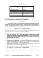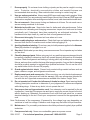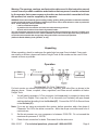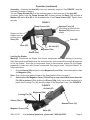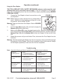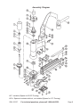
1
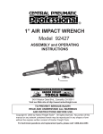
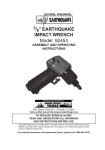
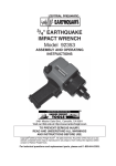
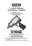
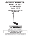
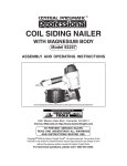
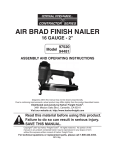
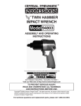
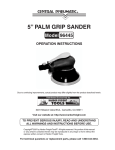
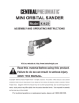
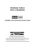
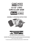
®
FLOOR STAPLER
WITH HAMMER
Model 93197
ASSEMBLY and OPERATING
INSTRUCTIONS
®
3491 Mission Oaks Blvd., Camarillo, CA 93011
Visit our Web site at http://www.harborfreight.com
Copyright© 2005 by Harbor Freight Tools®. All rights reserved. No portion of
this manual or any artwork contained herein may be reproduced in any shape or
form without the express written consent of Harbor Freight Tools.
For technical questions and replacement parts, please call 1-800-444-3353
Specifications
Air Inlet
Recommended Air Pressure
Maximum Air Pressure
Dimensions
Weight
Magazine Capacity
Air Consumption
Fastener Size Range
1/4” - 18 NPT
70-90 PSI
100 PSI
22-1/2” x 17-1/2” x 3-1/8”
21.85 Lbs.
80 Pcs. / Top Loaded
5.0 CFM @ 80 PSI
3/4” to 2” Long x 15 Gauge
Note: SKU 90429 - 2”, 15 Gauge Staples are available from Harbor Freight Tools.
Note: This Floor Stapler is designed for use on wood floors.
Save This Manual
You will need the manual for the safety warnings and precautions, assembly instructions,
operating and maintenance procedures, parts list and diagram. Keep your invoice with this
manual. Write the invoice number on the inside of the front cover. Keep the manual and
invoice in a safe and dry place for future reference.
Safety Warnings and Precautions
WARNING: When using tool, basic safety precautions should always be followed to
reduce the risk of personal injury and damage to equipment.
Read all instructions before using this tool!
1.
THIS TOOL DOES NOT USE A SAFETY MECHANISM; extreme caution must be
used whenever this tool is connected to an air supply. If the tool is dropped or if the
Hammer Face (10) is accidentally struck, then the tool will fire a staple, potentially causing
SEVERE PERSONAL INJURY.
2.
Keep work area clean. Cluttered areas invite injuries.
3.
Observe work area conditions. Do not use machines or power tools in damp or wet
locations. Don’t expose to rain. Keep work area well lighted. Do not use electrically
powered tools in the presence of flammable gases or liquids.
4.
Keep children away. Children must never be allowed in the work area. Do not let them
handle machines, tools, extension cords, or air hoses.
5.
Store idle equipment. When not in use, tools must be stored in a dry location to inhibit
rust. Always lock up tools and keep out of reach of children.
6.
Use the right tool for the job. Do not attempt to force a small tool or attachment to do
the work of a larger industrial tool. There are certain applications for which this tool was
designed. It will do the job better and more safely at the rate for which it was intended.
Do not modify this tool and do not use this tool for a purpose for which it was not intended.
SKU 93197
For technical questions, please call 1-800-444-3353.
Page 2
7.
Dress properly. Do not wear loose clothing or jewelry as they can be caught in moving
parts. Protective, electrically nonconductive clothes and nonskid footwear are
recommended when working. Wear restrictive hair covering to contain long hair.
8.
Use eye and ear protection. Always wear ANSI approved impact safety goggles. Wear
a full face shield if you are producing metal filings or wood chips. Wear an ANSI approved
dust mask or respirator when working around metal, wood, and chemical dusts and mists.
9.
Do not overreach. Keep proper footing and balance at all times. Do not reach over or
across running machines or air hoses.
10.
Maintain tools with care. Keep tools clean for better and safer performance. Follow
instructions for lubricating and changing accessories. Inspect tool cords and air hoses
periodically and, if damaged, have them repaired by an authorized technician. The
handles must be kept clean, dry, and free from oil and grease at all times.
11.
Disconnect air supply. Disconnect air hose when not in use.
12.
Remove adjusting keys and wrenches. Check that keys and adjusting wrenches are
removed from the tool or machine work surface before plugging it in.
13.
Avoid unintentional starting. Do not carry any tool with pressure applied to the Hammer
Face (10), whether it is plugged in or not.
14.
Stay alert. Watch what you are doing, use common sense. Do not operate any tool when
you are tired.
15.
Check for damaged parts. Before using any tool, any part that appears damaged should
be carefully checked to determine that it will operate properly and perform its intended
function. Check for alignment and binding of moving parts; any broken parts or mounting
fixtures; and any other condition that may affect proper operation. Any part that is damaged
should be properly repaired or replaced by a qualified technician. Do not use the tool if
any switch does not turn On and Off properly.
16.
Guard against electric shock. Prevent body contact with grounded surfaces such as
pipes, radiators, ranges, and refrigerator enclosures.
17.
Replacement parts and accessories. When servicing, use only identical replacement
parts. Use of any other parts will void the warranty. Only use accessories intended for
use with this tool. Approved accessories are available from Harbor Freight Tools.
18.
Do not operate tool if under the influence of alcohol or drugs. Read warning labels
if taking prescription medicine to determine if your judgement or reflexes are impaired
while taking drugs. If there is any doubt, do not operate the tool.
19.
Use proper size and type extension cord. If an extension cord is required for the air
compressor, it must be of the proper size and type to supply the correct current to the tool
without heating up. Otherwise, the extension cord could melt and catch fire, or cause
electrical damage to the tool. Check your compressor’s manual for the appropriate size
cord.
Note: Performance of the compressor (if powered by line voltage) may vary depending on
variations in local line voltage. Extension cord usage may also affect tool performance.
20.
Maintenance. For your safety, maintenance should be performed regularly by a qualified
technician.
21.
Compressed air only. Never use combustible gases as a power source.
SKU 93197
For technical questions, please call 1-800-444-3353.
Page 3
Warning: The warnings, cautions, and instructions discussed in this instruction manual
cannot cover all possible conditions and situations that may occur. It must be understood
by the operator that common sense and caution are factors which cannot be built into
this product, but must be supplied by the operator.
WARNING: Some dust created by power sanding, sawing, grinding, drilling, and other construction activities,
contain chemicals known [to the State of California] to cause cancer, birth defects or other reproductive
harm. Some examples of these chemicals are:
Lead from lead-based paints
Crystalline silica from bricks and cement or other masonry products
Arsenic and chromium from chemically treated lumber
Your risk from these exposures varies, depending on how often you do this type of work. To reduce your
exposure to these chemicals: work in a well ventilated area, and work with approved safety equipment,
such as those dust masks that are specially designed to filter out microscopic particles.
(California Health & Safety Code § 25249.5, et seq. )
Unpacking
When unpacking, check to make sure the parts listed on page 8 are included. If any parts
are missing or broken, please call Harbor Freight Tools at the number on the cover of this
manual as soon as possible
Operation
Floor
Stapler
1/4”-18 NPT
For best service you should incorporate an oiler, regulator, and inline filter, as shown in the
diagram above. Hoses, couplers, oilers, regulators, and filters are all available at Harbor
Freight Tools.
1.
You will need to prepare a 1/4” air connector (sold separately) to connect to the air inlet
on the Floor Stapler. First, wrap the 1/4” air connector (not included) with pipe thread
seal tape before threading it into the Air Inlet (47). Connect the 3/8” ID Air Source Hose
to the Air Inlet (47).
Note: If you are not using an automatic oiler system, before operation, add a few drops of
Pneumatic Tool Oil to the airline connection. Add a few drops more after each hour of
continual use.
2.
Set the air pressure on your compressor to between 70-90 PSI. Do not exceed the
maximum air pressure of 100 PSI.
3.
Check the air connection for leaks. Disconnect from the air source.
SKU 93197
For technical questions, please call 1-800-444-3353.
Page 4
Operation (continued)
Assembly - Attaching the Arm (48) is the only assembly required. See FIGURE 1 and the
Assembly Drawing on page 8.
The two Clamp Screws (44) fit in the recessed gaps on the lower part of the Arm (48).
As shown below, hold the Clamp Screws (44) in place around the Body (18) and add a
Washer (45) and a Nut (46) to the threaded ends of the Clamp Screws (44). Tighten them
securely.
FIGURE 1
Clamp Screws (44)
Staples exit the
Stapler from the
bottom of the
Shoe (28).
Hammer Face (10)
(Pounding on this with the
Hammer (49) shoots out a
staple.
Recessed
Gap
Arm (48)
Shoe (28)
Air Inlet (47)
Magazine (30a)
Sleeve (36a)
Loading the Stapler
Warning! Disconnect the Stapler from the air compressor whenever loading or servicing.
After disconnecting the Stapler from the air compressor, there could still be enough air pressure
to fire the Stapler. After the air compressor hose is disconnected, always fire the Stapler
repeatedly to make sure all of the air is expended. See page 6 under “Using the Stapler” for
firing instructions.
1.
Grip the Sleeve (36a) and pull out the Magazine Cover (33a). Insert the staples inside
the Magazine (30a).
Note: Only use the size staples listed on the Specifications Chart on page 2.
2.
Use caution, the Magazine Cover (33a) will try to snap closed with force when the
Pin (38) is pressed. While holding the Sleeve (36a) firmly, use a small screwdriver to
press in the Locking Pin (38) along the edge of the Magazine Cover. See FIGURE 2.
FIGURE 2
Air Inlet (47)
Magazine (30a)
Locking Pin (38)
Sleeve (36a)
Hammer Face (10)
Magazine Cover (33a)
Shoe (28)
SKU 93197
For technical questions, please call 1-800-444-3353.
Page 5
Operation (continued)
Using the Floor Stapler
THIS TOOL DOES NOT USE A SAFETY MECHANISM; extreme caution must be used
whenever this tool is connected to an air supply. If the tool is dropped or if the Hammer
Face (10) is accidentally struck, then the tool will fire a staple, potentially causing SEVERE
PERSONAL INJURY.
1.
Connect the Floor Stapler to the air hose and turn on the
FIGURE 3
air compressor.
Note: Before using on a floor, test the unit on a scrap piece of
wood. Adjust the driving depth by providing more or less
air pressure. Never exceed 100 PSI.
Warning! Keep your feet clear of the Stapler. Refer to FIGURES
1 and 3.
2.
Hold the Arm (48) securely with one hand and grip the
Hammer (49) with the other hand.
3.
Make sure the Shoe (28) is over the staple target position.
Press down hard so that the Shoe (28) is firmly contacting the floor, and then strike the
Hammer Face (10) with the Hammer (49) to drive out a staple. Lift the tool off of the
floor.
4.
Repeat the process until you are finished. Then, disconnect the Floor Stapler from the
air source.
Warning! After disconnecting the Stapler from the air compressor, there could still be enough
air pressure to fire the Stapler. After the air compressor hose is disconnected, always
fire the Stapler repeatedly to make sure all of the air is expended
Troubleshooting
Note: Have the following problems repaired by a qualified service technician.
PROBLEM
Air leaking in nose
CAUSE
1. Loose Nose Screws
2. Bumper is cracked/worn
SOLUTION
1. Tighten and recheck
2. Replace Bumper
Lack of Power, slow
to cycle.
1. Tool is too dry
2. Air Pressure is too low
3. Exhaust blocked
1. Lubricate
2. Check air supply equipment
3. Clean exhaust channel
Intermittent feeding
or no fastener
coming out
1. Damaged pusher spring
1. Replace Spring
2. Wrong size staple
2. Use correct size
3. Dirty magazine or wear-plate 3. Clean magazine and nose
Jammed Staple
1. Driver channel worn
2. Driver is broken/worn
3. Bent staples
SKU 93197
1. Replace wear plate
2. Replace driver
3. Use straight staples
For technical questions, please call 1-800-444-3353.
Page 6
Anytime any maintenance or repairs are done (including clearing jams), FIRST:
1.
2.
3.
4.
Disconnect the Stapler from the air hose.
Empty Magazine (30a) completely.
Attempt to fire the Stapler into a piece of scrap wood to ensure that it is disconnected
and is incapable of firing any staples.
Always leave Magazine Cover (33a) open during maintenance. The Magazine is
spring-loaded and may cause parts or a staple to fly out of the Stapler.
Clearing Jams
1.
2.
3.
5.
6.
7.
8.
9.
10.
11.
Disconnect tool from air hose, empty Magazine (30a) of staples, release any built-up
air pressure, and leave the magazine open, as explained above.
While doing this step and the next, hold the Stapler pointed away from you and any
other people or fragile objects. Remove all four Screws (11) and Washers (23a) on the
Driver Guide (22a).
Carefully lift the Driver Guide (22a) off and remove the jammed staple. Pliers may be
necessary to remove a stuck staple.
Inspect the driver on the end of the Piston Assembly (9) for bends or breakage. If it is
damaged, do not use the tool until it is repaired by a qualified technician.
Lightly oil the driver and replace the Driver Guide (22a). Replace and securely tighten
all of the Screws (11) and Washers (23a).
Reload the Stapler.
Reconnect the Stapler to the air hose.
Press the tip of the Stapler against an appropriate piece of scrap wood.
Test fire the Stapler several times, checking for proper operation.
Disconnect the Stapler, remove the staples, and store the Stapler in a location out of
children’s reach.
Maintenance
1.
2.
3.
Periodically lubricate all moving parts and pivots with a light oil.
Wipe down the Floor Stapler with a damp cloth. Do not use harsh detergents or solvents.
Check that the Shoe (28) and the Hammer Face (10) is clear of any dirt or debris.
PLEASE READ THE FOLLOWING CAREFULLY
THE MANUFACTURER AND/OR DISTRIBUTOR HAS PROVIDED THE PARTS DIAGRAM IN THIS MANUAL
AS A REFERENCE TOOL ONLY. NEITHER THE MANUFACTURER NOR DISTRIBUTOR MAKES ANY
REPRESENTATION OR WARRANTY OF ANY KIND TO THE BUYER THAT HE OR SHE IS QUALIFIED TO
MAKE ANY REPAIRS TO THE PRODUCT OR THAT HE OR SHE IS QUALIFIED TO REPLACE ANY PARTS
OF THE PRODUCT. IN FACT, THE MANUFACTURER AND/OR DISTRIBUTOR EXPRESSLY STATES THAT
ALL REPAIRS AND PARTS REPLACEMENTS SHOULD BE UNDERTAKEN BY CERTIFIED AND LICENSED
TECHNICIANS AND NOT BY THE BUYER. THE BUYER ASSUMES ALL RISK AND LIABILITY ARISING
OUT OF HIS OR HER REPAIRS TO THE ORIGINAL PRODUCT OR REPLACEMENT PARTS THERETO, OR
ARISING OUT OF HIS OR HER INSTALLATION OF REPLACEMENT PARTS THERETO.
SKU 93197
For technical questions, please call 1-800-444-3353.
Page 7
Parts List
Part
Description
Part
Description
1
Cylinder Bushing
26
Screw
2
Plunger
27
Spacer for 25/32" Flooring
3
0-ring
27a
Spacer for 1/2" Flooring
4
0-ring
28
Shoe
5
Poppet
29a
Pin
6
0-ring
30a
Magazine
7
0-ring
31a
Magazine Cap
8
0-ring
32a
Screw
9
Piston Assy.
33a
Magazine Cover
10
Hammer Face
34
Pin
11
Screw
35
Pin
12
Cylinder Cap
36a
Sleeve
13
0-ring
37
Detent Spring
14
Screw
38
Cover Latch Pin
15
Washer
40
Tension Spring
16
Poppet Actuator
41
Pusher
17
Gasket
42
Bushing
18
Body
43
Roller
19
Bumper
44
Clamp Screw
20a
Nose
45
Washer
21a
Screw
46
Nut
22a
Blade Guide
47
Air Inlet
23a
Washer
48
Arm
24
Washer
49
Hammer
25
Screw
NOTE: #27a - Spacer for 1/2” Flooring (Included but not installed)
NOTE: Some parts are listed and shown for illustration purposes only and are
not available individually as replacement parts.
SKU 93197
For technical questions, please call 1-800-444-3353.
Page 8
Assembly Diagram
#27 - Installed: (Spacer for 25/32” Flooring)
#27a - Spacer is included with tool, not installed (Spacer for 1/2” Flooring)
SKU 93197
For technical questions, please call 1-800-444-3353.
Page 9