1
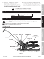
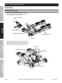
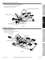
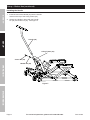
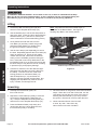
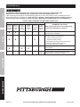
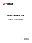
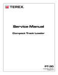
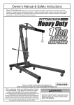
Table of Contents
Safety
Safety
Safety.......................................................... 2
Specifications.............................................. 3
Setup........................................................... 3
Operation..................................................... 8
Maintenance................................................ 9
Troubleshooting.......................................... 10
Parts Lists and Assembly Diagrams........... 12
Warranty..................................................... 16
WARNING SYMBOLS AND DEFINITIONS
This is the safety alert symbol. It is used to alert you to potential
personal injury hazards. Obey all safety messages that
follow this symbol to avoid possible injury or death.
Indicates a hazardous situation which, if not avoided,
will result in death or serious injury.
Indicates a hazardous situation which, if not avoided,
could result in death or serious injury.
SETUP
Assembly
Indicates a hazardous situation which, if not avoided,
could result in minor or moderate injury.
Addresses practices not related to personal injury.
IMPORTANT SAFETY INFORMATION
Failure to heed these warnings may result in personal injury and/or property damage:
Operation
Operation
1. Study, understand, and follow all instructions
before operating this device.
17. Keep hands away from the Lift Arms (8, 43)
when raising or lowering the Lift.
2. Do not exceed 1500 lb. rated capacity.
18. Stay alert. Watch what you are doing, and use
common sense when operating a Lift. Do not use
Lift while tired or under the influence of drugs,
alcohol, or medication. A moment of inattention while
operating lifts may result in serious personal injury
3. Use only on hard, level surfaces.
4. Load saddles equally.
5. Lifting device only. Immediately after lifting,
support the vehicle with appropriate means.
6. Do not adjust safety valve.
19. Never allow anyone to ride Lift when it is being raised,
lowered, or while holding an ATV or motorcycle.
7. Wear ANSI-approved safety goggles and
heavy-duty work gloves during use.
20. Before use, read manufacturer’s instruction
manual for the ATV or motorcycle being lifted.
8. Keep clear of load while lifting and lowering.
21. Store idle Lift out of reach of children and
other untrained persons. Lifts are dangerous
in the hands of untrained users.
9. Lower load slowly.
10. Do not use for aircraft purposes.
Maintenance
Maintenance
11. Lift vehicle only at manufacturerrecommended locations.
12. Inspect before every use; do not use
if parts are loose or damaged.
13. Secure load with appropriate restraint device.
14. Immediately after lifting load, ensure lift
mechanical load holding means is engaged.
15. Do not move or dolly the vehicle while on the Lift.
16. No alterations shall be made to this product.
Page 2
22. Lift service must be performed only by qualified repair
personnel. Service or maintenance performed by
unqualified personnel could result in a risk of injury.
23. When servicing the Lift, use only identical
replacement parts - refer to attached, productspecific parts lists and diagrams. Follow instructions
in the “Maintenance and Servicing” section of this
manual. Use of unauthorized parts or failure to follow
maintenance instructions may create a risk of injury.
24. Maintain labels and nameplates on the Lift. These
carry important information. If unreadable or missing,
contact Harbor Freight Tools for a replacement.
For technical questions, please call 1-800-444-3353.
Item 61632
26. The brass components of this product contain lead,
a chemical known to the State of California to cause
cancer, birth defects (or other reproductive harm).
(California Health & Safety code § 25249.5, et seq.)
Safety
Safety
25. The warnings, precautions, and instructions
discussed in this manual cannot cover all
possible conditions and situations that may occur.
The operator must understand that common sense
and caution are factors, which cannot be built into
this product, but must be supplied by the operator.
SAVE THESE INSTRUCTIONS.
Specifications
Maximum Capacity
1500 lb. (dead weight, evenly distributed)
Lift Range
4-3/4" to 16-3/8"
Dimensions
31-1/2" L x 16" W x 5-1/2" H
SETUP
Assembly
Setup – Before Use
Read the ENTIRE IMPORTANT SAFETY INFORMATION section at the beginning of this
manual including all text under subheadings therein before set up or use of this product.
Note: For additional information regarding the parts listed in the following pages,
refer to Parts Lists and Assembly Diagrams on page 12.
Lifting Frame
Bottle Jack
Stop Bar
Connecting Rod
Handle
Lift Saddle
with Rubber Pads
Operation
Operation
Components
Left Stop Bar
Foot Pedal
Release Pedal
Lock Bolt
Right Stop Bar
Rear Lift Arm
Front Lift Arm
Figure A
Item 61632
For technical questions, please call 1-800-444-3353.
Page 3
Maintenance
Maintenance
Stop Bar
Rod Clamp
Setup – Before Use (continued)
Lift Set Up
Safety
Safety
Mounting the Bottle Jack
1. Secure the Jack Assembly (30) to the Jack
Mounting Plate portion of the Bottom Base (13)
with two Bolts (23). See Figure B.
Bolt (23)
SETUP
Assembly
Bottle Jack (30)
Jack Mounting Plate
Bottom Base (13)
Figure B
Operation
Operation
2. Lift the Lifting Frame (36) onto the Jack’s ram
and place the Pin (25), on the upper end of the
Jack’s arm, into the bracket on the Lifting Frame,
securing it with the Bolt (35). See Figure C.
Pin (25)
Lifting Frame (36)
Bolt (35)
Maintenance
Maintenance
Bottle Jack (30)
Figure C
Page 4
For technical questions, please call 1-800-444-3353.
Item 61632
Installing the Stop Bar Connecting Rod
1. Insert the two ends of the Stop Bar Connecting Rod (40)
into the sleeves on the Right and Left Stop Bars (41, 44).
Safety
Safety
2. Secure the Stop Bar Connecting Rod in place
with two Nuts (42). See Figure D.
Stop Bar Connecting Rod (40)
SETUP
Assembly
Left Stop Bar (44)
Right Stop Bar (41)
Nut (42)
Figure D
Installing the Foot Pedal
1. Insert the Foot Pedal (27) into its
holder on the Bottle Jack (30).
Operation
Operation
2. Secure Foot Pedal in place using the Foot
Pedal Bolt (28). See Figure E.
Foot Pedal (27)
Bottle Jack (30)
Maintenance
Maintenance
Foot Pedal Bolt (28)
Figure E
Item 61632
For technical questions, please call 1-800-444-3353.
Page 5
Setup – Before Use (continued)
Installing the Handle
Safety
Safety
1. Insert the end of the Handle (34) into the handle
socket on the top of the Lifting Frame (36).
2. Secure the Handle in place with the Handle
Pin (29) and Cotter Pin (32). See Figure F.
SETUP
Assembly
Handle (34)
Lifting Frame (36)
Cotter Pin (32)
Operation
Operation
Handle Pin (29)
Figure F
Maintenance
Maintenance
Page 6
For technical questions, please call 1-800-444-3353.
Item 61632
IMPORTANT! Before first use, check for proper
hydraulic fluid level in the Bottle Jack (30). Then
thoroughly test the Lift for proper operation
prior to its actual use. If the Lift appears not
to be working properly, it may be necessary
to bleed its hydraulic system of excess air.
3. While holding the Release Pedal down,
quickly pump the Foot Pedal (27) up and down
several times to purge air from the system.
1. Remove the Fluid Fill Plug (39a) on
the side of the Bottle Jack (30).
5. Replace the Fluid Fill Plug.
2. Use one foot to step on and hold the
Release Pedal (13a) down.
4. Check the fluid fill hole and, if necessary, top
off the jack’s Fluid Reservoir (11a) with high
grade hydraulic fluid (sold separately).
6. Test the Lift several times for proper operation
before attempting to lift a load. If, after purging,
the Lift still does not appear to be working
properly, do not use the Lift until it has been
repaired by a qualified service technician.
Safety
Safety
Bleeding
1. Remove the Fluid Fill Plug (39a) on
the side of the Bottle Jack (30).
2. Add high grade hydraulic fluid (sold separately)
into the fluid fill hole slowly until the fluid
just begins to run out of the hole.
Maintenance
Maintenance
Operation
Operation
3. Replace the Fluid Fill Plug.
SETUP
Assembly
Adding Hydraulic Fluid
Item 61632
For technical questions, please call 1-800-444-3353.
Page 7
Operating Instructions
Safety
Safety
TO PREVENT SERIOUS INJURY: Do not work on the Lift, or leave it unattended if the Stop
Bars (41, 44) are not in the locked position, or the Lock Bolts (16) are not engaged (lifting the
Rear Wheels [17] off of the ground). Keep clear of Lift Arms (8, 43) during operation.
Lifting
1. Lift the Stop Bar Connecting Rod (40) and
secure it to the Stop Bar Rod Clamp (37).
2. Use the Handle (34) to roll the Lift and position it
next to the load. Lower the Lift by depressing the
Release Pedal (13a). (See ATV or motorcycle
owner’s manual for recommended lifting points.)
Note: Stop Bars fit behind the welded stops on
both sides of the Bottom Base. See Figure G
showing Stop Bars in the locked position.
SETUP
Assembly
3. Once positioned under the load, turn the
Lock Bolts (16) until they contact the ground
and lift the Rear Wheels (17) slightly off of
the ground to keep the Lift from rolling.
4. Use tie-down straps (sold separately) to secure
the load. Repeatedly depress the Foot Pedal (27)
slowly to raise the Lift. When the Lift makes
contact with the load, make sure the load sits
evenly on the Lift Saddle (2) before raising the
load. If the load is not evenly distributed on the
two Rubber Pads (3) or not secured in place with
tie-down straps, it may fall from the Lift, resulting
in personal injury and property damage.
Operation
Operation
5. Continue to raise the Lift to the desired height.
Disengage the Stop Bar Connecting Rod from
the clamp. Lock the Lift at one of the three
locking positions on the Bottom Base (13)
with the Stop Bars (41, 44) and lower Lift
slightly to securely engage the Stop Bars. Not
engaging the Stop Bars may result in serious
injury or death, and damage the Lift.
Stop Bar (41)
Welded stops on Bottom Base (13)
Figure G
Lowering
1. Carefully remove all tools, parts, etc.
from under the Lift.
Maintenance
Maintenance
2. Depress the Foot Pedal (27) slowly to raise the
Lift enough to disengage the Stop Bars (41,
44). Lift up the Stop Bar Connecting Rod (40)
and secure it to the Stop Bar Rod Clamp (37).
3. Press the Release Pedal (13a) slowly and
gently lower the load. Never allow the load
to come down quickly or suddenly.
Page 8
4. Once the load is on the ground, remove the tie-down
straps. When the Lift is clear of the load, turn the
Lock Bolts (16) until they are clear of the ground,
allowing the Rear Wheels (17) to firmly contact
the ground. Roll the Lift out from under the load.
5. Clean external surfaces of the Lift with
a clean, dry cloth. Store Lift in dry,
indoor area out of reach of children.
For technical questions, please call 1-800-444-3353.
Item 61632
Maintenance and Servicing
Safety
Safety
Procedures not specifically explained in this manual must
be performed only by a qualified technician.
TO PREVENT SERIOUS INJURY FROM TOOL FAILURE: Do not use damaged equipment.
If abnormal noise or vibration occurs, have the problem corrected before further use.
Cleaning, Maintenance, and Lubrication
• broken, cracked, or bent parts
• loose or missing parts
• any other condition that may
affect its safe operation.
If a problem occurs, have the problem
corrected before further use.
Do not use damaged equipment.
2. Before each use, thoroughly test the Lift
for proper operation prior to its actual use.
If the Lift appears not to be working properly,
follow Bleeding instructions on page 7.
3. Change the hydraulic fluid at least
once every three years:
a. With the Lift fully lowered, remove the Fluid Fill
Plug (39a) on the side of the Bottle Jack (30).
b. With assistance, place the Lift on its side to
allow the old hydraulic fluid to drain out of
the jack’s Fluid Reservoir (11a) completely,
and dispose of the old hydraulic fluid in
accordance with local regulations.
c. With the Lift upright, completely fill the jack’s
Fluid Reservoir with a high quality hydraulic
fluid (sold separately) until the fluid just
begins to run out of the fluid fill hole.
SETUP
Assembly
1. BEFORE EACH USE, inspect the general
condition of the Lift. Check for:
d. Reinstall the Fluid Fill Plug.
Maintenance
Maintenance
Operation
Operation
4. Wipe dry with a clean cloth. Store the Lift in
a safe, dry location out of reach of children
and other non-authorized people.
Item 61632
For technical questions, please call 1-800-444-3353.
Page 9
Troubleshooting
Safety
Safety
TO PREVENT SERIOUS INJURY: Use caution when troubleshooting a malfunctioning lift.
Stay well clear of the supported load. Completely resolve all problems before use.
If the solutions presented in the Troubleshooting guide do not solve the problem, have a qualified technician
inspect and repair the Lift before use. After the Lift is repaired: Test it carefully without a load by raising it
and lowering it fully, checking for proper operation, BEFORE RETURNING THE LIFT TO OPERATION.
DO NOT USE A DAMAGED OR MALFUNCTIONING LIFT!
POSSIBLE SYMPTOMS
Unit will
not lift at
its weight
capacity
Saddle
lowers
under
load
X
X
Pump
stroke
feels
spongy
Saddle
will not
lift all the
way
Handle
moves up
when jack
is under
load
PROBABLE SOLUTION
Fluid
leaking (Make certain that the lift is not supporting
from filler a load while attempting a solution.)
plug
Check that Release Pedal is not
stuck and raises completely.
SETUP
Assembly
Valves may be blocked and may not close fully.
To flush the valves, with assistance:
X
X
1. Lower the Lifting Frame and
release the Release Pedal.
X
2. Manually lift the Lifting Frame several inches.
3. Press the Release Pedal and force
the Lifting Frame down quickly.
X
X
Jack may be low on fluid. Check the fluid level and
refill if needed.
X
Jack may require bleeding – see page 7.
X
Unit may have too much hydraulic fluid inside.
Check fluid level and adjust if needed.
Operation
Operation
Maintenance
Maintenance
Page 10
For technical questions, please call 1-800-444-3353.
Item 61632
Maintenance
Maintenance
Operation
Operation
SETUP
Assembly
THE MANUFACTURER AND/OR DISTRIBUTOR HAS PROVIDED THE PARTS LIST AND ASSEMBLY DIAGRAM
IN THIS MANUAL AS A REFERENCE TOOL ONLY. NEITHER THE MANUFACTURER OR DISTRIBUTOR
MAKES ANY REPRESENTATION OR WARRANTY OF ANY KIND TO THE BUYER THAT HE OR SHE IS
QUALIFIED TO MAKE ANY REPAIRS TO THE PRODUCT, OR THAT HE OR SHE IS QUALIFIED TO REPLACE
ANY PARTS OF THE PRODUCT. IN FACT, THE MANUFACTURER AND/OR DISTRIBUTOR EXPRESSLY
STATES THAT ALL REPAIRS AND PARTS REPLACEMENTS SHOULD BE UNDERTAKEN BY CERTIFIED AND
LICENSED TECHNICIANS, AND NOT BY THE BUYER. THE BUYER ASSUMES ALL RISK AND LIABILITY
ARISING OUT OF HIS OR HER REPAIRS TO THE ORIGINAL PRODUCT OR REPLACEMENT PARTS
THERETO, OR ARISING OUT OF HIS OR HER INSTALLATION OF REPLACEMENT PARTS THERETO.
Safety
Safety
PLEASE READ THE FOLLOWING CAREFULLY
Record Product’s Serial Number Here:
Note: If product has no serial number, record month and year of purchase instead.
Note: Some parts are listed and shown for illustration purposes only,
and are not available individually as replacement parts.
Item 61632
For technical questions, please call 1-800-444-3353.
Page 11
Parts Lists and Assembly Diagrams
Main Parts List
Safety
Safety
Part
SETUP
Assembly
1
2
3
4
5
6
7
8
9
10
11
12
13
14
15
16
17
18
19
20
21
22
Description
Nylon Ring
Lift Saddle
Rubber Pad
Bolt
Washer
Washer
Nut
Front Lift Arm
Nut
Washer
Front Wheel
Bolt
Bottom Base
Pin
Cotter Pin
Lock Bolt Assembly
Rear Wheel
Washer
Washer
Nut
Bolt
Nut
Qty
2
1
2
6
10
4
4
1
4
2
2
2
1
4
4
2
2
2
2
2
1
2
Part
23
24
25
26
27
28
29
30
31
32
33
34
35
36
37
38
39
40
41
42
43
44
Description
Bolt M8 x 30
Spring
Pin
Rubber Pad
Foot Pedal
Foot Pedal Bolt M8 x 16
Handle Pin
Bottle Jack
Cotter Pin
Cotter Pin
Handle Sleeve
Handle
Bolt
Lifting Frame
Stop Bar Rod Clamp
Bolt
Washer
Stop Bar Connecting Rod
Right Stop Bar
Nut M8
Rear Lift Arm
Left Stop Bar
Qty
2
1
1
1
1
1
1
1
1
1
2
1
1
1
1
1
1
1
1
2
1
1
Operation
Operation
Maintenance
Maintenance
Page 12
For technical questions, please call 1-800-444-3353.
Item 61632
Item 61632
For technical questions, please call 1-800-444-3353.
7
8
2
11
Maintenance
Maintenance
5
6
4
3
12
10
9
1
Page 13
14
42
Operation
Operation
13
15
5
43
41
4
44
40
16
5
36
39
9
17
31
32
23
30
20
19
18
37
35
24
22
29
21
SETUP
Assembly
38
22
25
27
28
26
Safety
Safety
33
34
Main Assembly Diagram
Parts List A – Bottle Jack (30)
Part
Safety
Safety
1a
2a
3a
4a
5a
6a
7a
8a
9a
10a
11a
12a
13a
14a
15a
16a
17a
18a
19a
20a
21a
22a
23a
Description
SETUP
Assembly
Ram Cap
Ram O-Ring
Top Sealing Gasket
Ram Assembly
Retaining Ring
Piston Head
Ram Gasket
O-Ring
Cylinder
Cylinder Sealing Gasket
Fluid Reservoir
Reservoir Sealing Gasket
Release Pedal
O-Ring
Release Valve Rod
Split Cotter Pin
Pin
Base
Ball
Ball
Screw
Pin
Ball
Qty
1
1
1
1
1
1
1
1
1
1
1
1
1
1
1
2
1
1
3
2
2
3
1
Part
24a
25a
26a
27a
28a
29a
30a
31a
32a
33a
34a
35a
36a
37a
38a
39a
40a
41a
42a
43a
44a
45a
Description
Spring Plunger
Spring
Screw
O-Ring
Screw
Screw
Sealing Ring
Spring
Spring
Throttle Valve
Washer
Lower Spring Retainer
Spring
Pump Cylinder
Upper Spring Retainer
Fluid Fill Plug
O-Ring
Seal
Piston Rod
Split Cotter Pin
Link
Handle Socket
Qty
2
1
1
1
1
1
1
1
1
1
1
1
1
1
1
1
1
1
1
1
1
1
Operation
Operation
Maintenance
Maintenance
Page 14
For technical questions, please call 1-800-444-3353.
Item 61632
Safety
Safety
Assembly Diagram A – Bottle Jack (30)
1a
2a
3a
45a
5a
6a
22a
43a
7a
22a
8a
41a
39a
40a
38a
11a
19a
17a
19a
36a
32a
35a
34a
24a
18a
20a
19a
21a
22a
16a
Item 61632
33a
23a
24a
31a
25a
Maintenance
Maintenance
16a
37a
12a
15a
Operation
Operation
42a
10a
14a
44a
16a
9a
13a
SETUP
Assembly
4a
29a
30a
26a
For technical questions, please call 1-800-444-3353.
28a
27a
Page 15
Limited 90 Day Warranty
Harbor Freight Tools Co. makes every effort to assure that its products meet high quality and durability standards,
and warrants to the original purchaser that this product is free from defects in materials and workmanship for the
period of 90 days from the date of purchase. This warranty does not apply to damage due directly or indirectly,
to misuse, abuse, negligence or accidents, repairs or alterations outside our facilities, criminal activity, improper
installation, normal wear and tear, or to lack of maintenance. We shall in no event be liable for death, injuries
to persons or property, or for incidental, contingent, special or consequential damages arising from the use of
our product. Some states do not allow the exclusion or limitation of incidental or consequential damages, so the
above limitation of exclusion may not apply to you. THIS WARRANTY IS EXPRESSLY IN LIEU OF ALL OTHER
WARRANTIES, EXPRESS OR IMPLIED, INCLUDING THE WARRANTIES OF MERCHANTABILITY AND FITNESS.
To take advantage of this warranty, the product or part must be returned to us with transportation charges
prepaid. Proof of purchase date and an explanation of the complaint must accompany the merchandise.
If our inspection verifies the defect, we will either repair or replace the product at our election or we may
elect to refund the purchase price if we cannot readily and quickly provide you with a replacement. We will
return repaired products at our expense, but if we determine there is no defect, or that the defect resulted
from causes not within the scope of our warranty, then you must bear the cost of returning the product.
This warranty gives you specific legal rights and you may also have other rights which vary from state to state.
3491 Mission Oaks Blvd. • PO Box 6009 • Camarillo, CA 93011 • (800) 444-3353