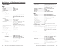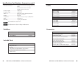
1
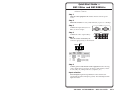
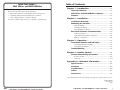
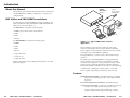
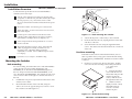
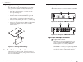
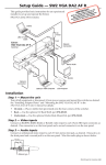
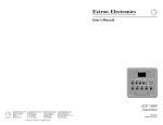
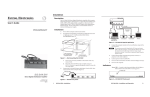
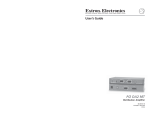
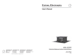
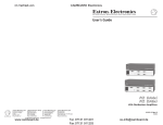
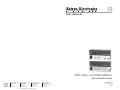
User’s Manual
SW2 VGAcc and SW2 RGBHVcc
VGA and RGBHV switchers
www.extron.com
Extron Electronics, USA
Extron Electronics, Europe
Extron Electronics, Asia
Extron Electronics, Japan
1230 South Lewis Street
Anaheim, CA 92805
USA
714.491.1500
Fax 714.491.1517
Beeldschermweg 6C
3821 AH Amersfoort
The Netherlands
+31.33.453.4040
Fax +31.33.453.4050
135 Joo Seng Road, #04-01
PM Industrial Building
Singapore 368363
+65.6383.4400
Fax +65.6383.4664
Daisan DMJ Building 6F
3-9-1 Kudan Minami
Chiyoda-ku, Tokyo 102-0074 Japan
+81.3.3511.7655
Fax +81.3.3511.7656
© 2004 Extron Electronics. All rights reserved.
68-965-01 Rev. A
Printed in USA
09 04
Precautions
Safety Instructions • English
This symbol is intended to alert the user of important
operating and maintenance (servicing) instructions
in the literature provided with the equipment.
This symbol is intended to alert the user of the
presence of uninsulated dangerous voltage within
the product's enclosure that may present a risk of
electric shock.
Caution
Read Instructions • Read and understand all safety and operating
instructions before using the equipment.
Retain Instructions • The safety instructions should be kept for future
reference.
Follow Warnings • Follow all warnings and instructions marked on the
equipment or in the user information.
Avoid Attachments • Do not use tools or attachments that are not
recommended by the equipment manufacturer because they may be
hazardous.
Consignes de Sécurité • Français
Ce symbole sert à avertir l’utilisateur que la
documentation fournie avec le matériel contient des
instructions importantes concernant l’exploitation
et la maintenance (réparation).
Ce symbole sert à avertir l’utilisateur de la présence
dans le boîtier de l’appareil de tensions dangereuses
non isolées posant des risques d’électrocution.
Attention
Lire les instructions• Prendre connaissance de toutes les consignes de
sécurité et d’exploitation avant d’utiliser le matériel.
Conserver les instructions• Ranger les consignes de sécurité afin de
pouvoir les consulter à l’avenir.
Respecter les avertissements • Observer tous les avertissements et
consignes marqués sur le matériel ou présentés dans la documentation
utilisateur.
Eviter les pièces de fixation • Ne pas utiliser de pièces de fixation ni
d’outils non recommandés par le fabricant du matériel car cela
risquerait de poser certains dangers.
Sicherheitsanleitungen • Deutsch
Dieses Symbol soll dem Benutzer in der im
Lieferumfang enthaltenen Dokumentation
besonders wichtige Hinweise zur Bedienung und
Wartung (Instandhaltung) geben.
Dieses Symbol soll den Benutzer darauf aufmerksam
machen, daß im Inneren des Gehäuses dieses
Produktes gefährliche Spannungen, die nicht isoliert
sind und die einen elektrischen Schock verursachen
können, herrschen.
Achtung
Lesen der Anleitungen • Bevor Sie das Gerät zum ersten Mal verwenden,
sollten Sie alle Sicherheits-und Bedienungsanleitungen genau
durchlesen und verstehen.
Aufbewahren der Anleitungen • Die Hinweise zur elektrischen Sicherheit
des Produktes sollten Sie aufbewahren, damit Sie im Bedarfsfall darauf
zurückgreifen können.
Befolgen der Warnhinweise • Befolgen Sie alle Warnhinweise und
Anleitungen auf dem Gerät oder in der Benutzerdokumentation.
Keine Zusatzgeräte • Verwenden Sie keine Werkzeuge oder Zusatzgeräte,
die nicht ausdrücklich vom Hersteller empfohlen wurden, da diese eine
Gefahrenquelle darstellen können.
Instrucciones de seguridad • Español
Este símbolo se utiliza para advertir al usuario sobre
instrucciones importantes de operación y
mantenimiento (o cambio de partes) que se desean
destacar en el contenido de la documentación
suministrada con los equipos.
Este símbolo se utiliza para advertir al usuario sobre
la presencia de elementos con voltaje peligroso sin
protección aislante, que puedan encontrarse dentro
de la caja o alojamiento del producto, y que puedan
representar riesgo de electrocución.
Precaucion
Leer las instrucciones • Leer y analizar todas las instrucciones de
operación y seguridad, antes de usar el equipo.
Conservar las instrucciones • Conservar las instrucciones de seguridad
para futura consulta.
Obedecer las advertencias • Todas las advertencias e instrucciones
marcadas en el equipo o en la documentación del usuario, deben ser
obedecidas.
Evitar el uso de accesorios • No usar herramientas o accesorios que no
sean especificamente recomendados por el fabricante, ya que podrian
implicar riesgos.
Extron’s Warranty
Warning
Power sources • This equipment should be operated only from the power source
indicated on the product. This equipment is intended to be used with a main
power system with a grounded (neutral) conductor. The third (grounding) pin is
a safety feature, do not attempt to bypass or disable it.
Power disconnection • To remove power from the equipment safely, remove all
power cords from the rear of the equipment, or the desktop power module (if
detachable), or from the power source receptacle (wall plug).
Power cord protection • Power cords should be routed so that they are not likely to
be stepped on or pinched by items placed upon or against them.
Servicing • Refer all servicing to qualified service personnel. There are no userserviceable parts inside. To prevent the risk of shock, do not attempt to service
this equipment yourself because opening or removing covers may expose you to
dangerous voltage or other hazards.
Slots and openings • If the equipment has slots or holes in the enclosure, these are
provided to prevent overheating of sensitive components inside. These openings
must never be blocked by other objects.
Lithium battery • There is a danger of explosion if battery is incorrectly replaced.
Replace it only with the same or equivalent type recommended by the
manufacturer. Dispose of used batteries according to the manufacturer's
instructions.
Extron Electronics warrants this product against defects in materials and
workmanship for a period of three years from the date of purchase. In the event of
malfunction during the warranty period attributable directly to faulty workmanship
and/or materials, Extron Electronics will, at its option, repair or replace said products
or components, to whatever extent it shall deem necessary to restore said product to
proper operating condition, provided that it is returned within the warranty period,
with proof of purchase and description of malfunction to:
USA, Canada, South America,
and Central America:
Extron Electronics
Avertissement
1001 East Ball Road
Alimentations• Ne faire fonctionner ce matériel qu’avec la source d’alimentation
indiquée sur l’appareil. Ce matériel doit être utilisé avec une alimentation
principale comportant un fil de terre (neutre). Le troisième contact (de mise à la
terre) constitue un dispositif de sécurité : n’essayez pas de la contourner ni de la
désactiver.
Déconnexion de l’alimentation• Pour mettre le matériel hors tension sans danger,
déconnectez tous les cordons d’alimentation de l’arrière de l’appareil ou du
module d’alimentation de bureau (s’il est amovible) ou encore de la prise secteur.
Protection du cordon d’alimentation • Acheminer les cordons d’alimentation de
manière à ce que personne ne risque de marcher dessus et à ce qu’ils ne soient
pas écrasés ou pincés par des objets.
Réparation-maintenance • Faire exécuter toutes les interventions de réparationmaintenance par un technicien qualifié. Aucun des éléments internes ne peut être
réparé par l’utilisateur. Afin d’éviter tout danger d’électrocution, l’utilisateur ne
doit pas essayer de procéder lui-même à ces opérations car l’ouverture ou le
retrait des couvercles risquent de l’exposer à de hautes tensions et autres dangers.
Fentes et orifices • Si le boîtier de l’appareil comporte des fentes ou des orifices,
ceux-ci servent à empêcher les composants internes sensibles de surchauffer. Ces
ouvertures ne doivent jamais être bloquées par des objets.
Lithium Batterie • Il a danger d'explosion s'll y a remplacment incorrect de la
batterie. Remplacer uniquement avec une batterie du meme type ou d'un ype
equivalent recommande par le constructeur. Mettre au reut les batteries usagees
conformement aux instructions du fabricant.
Anaheim, CA 92805, USA
Vorsicht
Stromquellen • Dieses Gerät sollte nur über die auf dem Produkt angegebene
Stromquelle betrieben werden. Dieses Gerät wurde für eine Verwendung mit
einer Hauptstromleitung mit einem geerdeten (neutralen) Leiter konzipiert. Der
dritte Kontakt ist für einen Erdanschluß, und stellt eine Sicherheitsfunktion dar.
Diese sollte nicht umgangen oder außer Betrieb gesetzt werden.
Stromunterbrechung • Um das Gerät auf sichere Weise vom Netz zu trennen,
sollten Sie alle Netzkabel aus der Rückseite des Gerätes, aus der externen
Stomversorgung (falls dies möglich ist) oder aus der Wandsteckdose ziehen.
Schutz des Netzkabels • Netzkabel sollten stets so verlegt werden, daß sie nicht
im Weg liegen und niemand darauf treten kann oder Objekte darauf- oder
unmittelbar dagegengestellt werden können.
Wartung • Alle Wartungsmaßnahmen sollten nur von qualifiziertem
Servicepersonal durchgeführt werden. Die internen Komponenten des Gerätes
sind wartungsfrei. Zur Vermeidung eines elektrischen Schocks versuchen Sie in
keinem Fall, dieses Gerät selbst öffnen, da beim Entfernen der Abdeckungen die
Gefahr eines elektrischen Schlags und/oder andere Gefahren bestehen.
Schlitze und Öffnungen • Wenn das Gerät Schlitze oder Löcher im Gehäuse
aufweist, dienen diese zur Vermeidung einer Überhitzung der empfindlichen
Teile im Inneren. Diese Öffnungen dürfen niemals von anderen Objekten
blockiert werden.
Litium-Batterie • Explosionsgefahr, falls die Batterie nicht richtig ersetzt wird.
Ersetzen Sie verbrauchte Batterien nur durch den gleichen oder einen
vergleichbaren Batterietyp, der auch vom Hersteller empfohlen wird. Entsorgen
Sie verbrauchte Batterien bitte gemäß den Herstelleranweisungen.
Advertencia
Alimentación eléctrica • Este equipo debe conectarse únicamente a la fuente/tipo
de alimentación eléctrica indicada en el mismo. La alimentación eléctrica de este
equipo debe provenir de un sistema de distribución general con conductor
neutro a tierra. La tercera pata (puesta a tierra) es una medida de seguridad, no
puentearia ni eliminaria.
Desconexión de alimentación eléctrica • Para desconectar con seguridad la
acometida de alimentación eléctrica al equipo, desenchufar todos los cables de
alimentación en el panel trasero del equipo, o desenchufar el módulo de
alimentación (si fuera independiente), o desenchufar el cable del receptáculo de
la pared.
Protección del cables de alimentación • Los cables de alimentación eléctrica se
deben instalar en lugares donde no sean pisados ni apretados por objetos que se
puedan apoyar sobre ellos.
Reparaciones/mantenimiento • Solicitar siempre los servicios técnicos de personal
calificado. En el interior no hay partes a las que el usuario deba acceder. Para
evitar riesgo de electrocución, no intentar personalmente la reparación/
mantenimiento de este equipo, ya que al abrir o extraer las tapas puede quedar
expuesto a voltajes peligrosos u otros riesgos.
Ranuras y aberturas • Si el equipo posee ranuras o orificios en su caja/alojamiento,
es para evitar el sobrecalientamiento de componentes internos sensibles. Estas
aberturas nunca se deben obstruir con otros objetos.
Batería de litio • Existe riesgo de explosión si esta batería se coloca en la posición
incorrecta. Cambiar esta batería únicamente con el mismo tipo (o su equivalente)
recomendado por el fabricante. Desachar las baterías usadas siguiendo las
instrucciones del fabricante.
Asia:
Extron Electronics, Asia
135 Joo Seng Road, #04-01
PM Industrial Bldg.
Singapore 368363
Europe, Africa, and the Middle East:
Extron Electronics, Europe
Beeldschermweg 6C
3821 AH Amersfoort
The Netherlands
Japan:
Extron Electronics, Japan
Daisan DMJ Bldg. 6F,
3-9-1 Kudan Minami
Chiyoda-ku, Tokyo 102-0074
Japan
This Limited Warranty does not apply if the fault has been caused by misuse,
improper handling care, electrical or mechanical abuse, abnormal operating conditions
or non-Extron authorized modification to the product.
If it has been determined that the product is defective, please call Extron and ask for an
Applications Engineer at (714) 491-1500 (USA), 31.33.453.4040 (Europe), 65.6383.4400
(Asia), or 81.3.3511.7655 (Japan) to receive an RA# (Return Authorization number). This
will begin the repair process as quickly as possible.
Units must be returned insured, with shipping charges prepaid. If not insured, you
assume the risk of loss or damage during shipment. Returned units must include the
serial number and a description of the problem, as well as the name of the person to
contact in case there are any questions.
Extron Electronics makes no further warranties either expressed or implied with
respect to the product and its quality, performance, merchantability, or fitness for any
particular use. In no event will Extron Electronics be liable for direct, indirect, or
consequential damages resulting from any defect in this product even if Extron
Electronics has been advised of such damage.
Please note that laws vary from state to state and country to country, and that some
provisions of this warranty may not apply to you.
Quick Start Guide —
SW2 VGAcc and SW2 RGBHVcc
Install and operate the SW2 VGAcc and SW2 RGBHVcc
switchers as follows:
Step 1
Turn all of the equipment off and disconnect it from the power
source.
Step 2
Mount the switcher in a rack, under furniture, or place on a desktop.
INPUTS
Step 3
2
1
Connect the input cables (VGA or
BNC) as shown at right.
Step 4
Connect the video output cable(s).
Step 5
R
G
INPUTS
B
H
V
R
G
B
H
V
1
2
Wire the contact closure/tally out
connector appropriately as shown below.
CONTACT
TALLY
OUT
1 2
1 2
(1) (2) (3) (4) (5)
PIN
1
2
3
4
5
Tally
Out
—
—
Gnd
In #1
In #2
Contact
Closure
Function
In #1 Input #1 (contact)
In #2 Input #2 (contact)
Ground
Gnd
—
Input #1 (tally)
Input #2 (tally)
—
Step 6
Connect power cords and turn on the equipment in the following
order: output devices (projectors, monitors), SW2 switcher, contact
closure/tally out, and input devices (computers, etc.).
Input selection
Select an input using the front panel buttons or the contact closure
(momentarily short the control pin to ground). The selected input’s LED
lights when active.
SW2 VGAcc and SW2 RGBHVcc • Quick Start Guide
QS-1
Quick Start Guide —
SW2 VGAcc and SW2 RGBHVcc
Troubleshooting
If the picture does not appear, do the following:
• Ensure that all devices are plugged in and receiving power.
• Check the cabling and make adjustments as needed.
• Select a different input to check for a display.
For more troubleshooting scenarios, see chapter 3, Troubleshooting.
Table of Contents
Chapter 1 • Introduction .......................................................... 1-1
About this Manual ....................................................... 1-2
SW2 VGAcc and SW2 RGBHVcc switchers .................. 1-2
Features ...................................................................................... 1-3
Chapter 2 • Installation ............................................................ 2-1
Installation Overview .......................................................... 2-2
Mounting the Switcher ...................................................... 2-2
Rack mounting ....................................................................... 2-2
Furniture mounting ............................................................... 2-3
Through-desk mounting ....................................................... 2-4
Rear Panel Features and Connections ......................... 2-4
Power connection .................................................................. 2-5
Signal input and output connections ................................... 2-5
Remote connection .............................................................. 2-6
Chapter 3 • Operation ................................................................ 3-1
Front Panel Controls and Indicators ............................ 3-2
Front panel buttons and LEDs .............................................. 3-2
Front panel operations .......................................................... 3-2
Troubleshooting ..................................................................... 3-2
Chapter 4 • Remote Control .................................................. 4-1
Contact Closure/Tally Out Control ................................. 4-2
Contact closure ...................................................................... 4-2
Tally out .................................................................................. 4-2
Appendix A • Reference Information ............................ A-1
Specifications ......................................................................... A-2
Switchers .................................................................................. A-4
Included Parts ......................................................................... A-4
Cables .......................................................................................... A-5
Accessories ............................................................................... A-5
All trademarks mentioned in this manual are the properties of their respective owners.
68-965-01 Rev. A
Printed in USA
09 04
QS-2
SW2 VGAcc and SW2 RGBHVcc • Quick Start Guide
SW2 VGAcc and SW2 RGBHVcc • Table of Contents
i
Table of Contents, cont’d
SW2 VGAcc and SW2 RBGHVcc
1
Chapter One
Introduction
About this Manual
SW2 VGAcc and SW2 RGBHVcc Switchers
Features
ii
SW2 VGAcc and SW2 RGBHVcc • Table of Contents
Introduction
About this Manual
Extron
SW2 VGAcc
Switcher
This manual contains information about the Extron SW2 VGAcc
and SW2 RGBHVcc switchers, detailing how to operate and
configure them.
2-button
Contact Closure
with Tally LEDs
Y
LL
TA T
OU
AC
NT
T
CO
SW2 VGAcc and SW2 RGBHVcc switchers
OU
TP
SW
The SW2 VGAcc and SW2 RGBHVcc are input switchers, each
with one buffered output and 350 MHz (-3dB) bandwidth (the
SW2 VGAcc is shown in figure 1-1).
INP
0.2
10
0-24
50
A
UTS
1
UT
1
2
V
2
2
cc
GA
2
1
0V
/60
Hz
LCD
Projector
The SW2 VGAcc accepts the following signals:
• RGBHV (VGA/SVGA/XGA/XGA2/UXGA)
• RGBS
Computer
• RGsB
Laptop
• RsGsBs
The SW2 RGBHVcc accepts the following signals:
• RGBHV
• RGBS
• RGsB
• RsGsBs
• component video
• S-video (Y/C)
• composite video
With an optional Mac/VGA adapter, both switchers can switch
Macintosh signals.
Figure 1-1 — Typical SW2 VGAcc switcher
application
These switchers are housed in 1U, half rack, and 6" deep
enclosures with internal universal 100 - 240 VAC 50/60 Hz
power supplies. Both models provide contact closure and tally
out remote control and feedback capability.
Front panel buttons or contact closure can be used for input
selection.
The SW2 VGAcc and SW2 RGBHVcc are high performance
video switchers. These switchers are designed to route high
resolution source signals to a video projector, monitor, or LCD
panel. Users may select the desired input channel using the
front panel Channel Select button or via remote control by using
a wired remote, a third-party control system, or any other
device capable of providing a momentary contact closure.
Features
350 MHz Video Bandwidth — The SW2 models provide high
performance, ultra-high resolution video signals with no
signal loss.
Front Panel Channel Selection Button and LED indicators
Contact closure /Tally Out — Contact closure allows for remote
selection of an input channel using contact closure.
A tally out status pin provides feedback to a control
system to indicate which input is currently selected.
1-2
SW2 VGAcc and SW2 RGBHVcc • Introduction
SW2 VGAcc and SW2 RGBHVcc • Introduction
1-3
Introduction, cont’d
Rack Mountable — The units rack mount into a 1U rack space
using the optional 19" 1U Universal rack shelf or 6" deep
1U rack shelf. Two units can mount side-by-side on a
single rack shelf.
SW2 VGAcc and SW2 RBGHVcc
2
Chapter Two
Installation
Installation Overview
Mounting the Switcher
Rear Panel Features and Connections
1-4
SW2 VGAcc and SW2 RGBHVcc • Introduction
Installation
Installation Overview
SW2 VGAcc_RGBHVcc User'sManl.pdf
6" Deep Rack Shelf
1/2 Rack Width Front False
Faceplate
To install and set up the SW2 VGAcc and SW2 RGBHVcc
switchers, follow these steps:
1
Turn all of the equipment off. Make sure that the video
(computers or other devices), the SW2 switcher, the output
devices (projectors, etc.), and contact closure control
device are all turned off and disconnected from the power
source.
2
Mount the switcher. See Mounting the Switcher, below.
3
Attach the cables. See Rear Panel Features and Connections,
later in this chapter.
4
Connect power cords and turn on the devices in the
following order: output devices (projectors, monitors),
SW2 switcher, and input devices (computers, etc.).
5
Select an input from the front panel buttons or contact
closure controller.
6
The picture should now appear. If not, ensure that all
cables are plugged in correctly and all devices are
receiving power. Check the cabling and make
adjustments as needed. Select a different input to check
for a display.
If problems occur, see chapter 3, Troubleshooting.
Mounting the Switcher
Rack mounting
For rack mounting, mount the SW2 VGAcc and SW2 RGBHVcc
on the optional 1U Universal Rack Shelf (Extron part
#60-190-01), the 1U Basic Rack Shelf (#60-604-01) (figure 2-1),
the 1U 6" Deep Universal Rack Shelf Kit (#60-190-10), or the
1U 6" Basic Rack Shelf (#60-604-10). The switcher mounts in one
of two locations: either to the right or to the left at the front of
the rack.
1.
If rubber feet were previously installed on the bottom of the
switcher, remove them.
2.
Mount the SW2 switcher on the rack shelf, using two
4-40 x 3/16 screws in opposite (diagonal) corners to secure
the switcher to the shelf (figure 2-1).
Front false
faceplate
uses 2
screws.
(2) 4-40 x 3/16"
Screws
Use 2 mounting holes on
opposite corners.
Figure 2-1 — Rack mounting the switcher
3.
Attach a blank panel or other unit(s) to the rack shelf.
4.
Insert the shelf into the rack, aligning the holes in the shelf
with those of the rack.
5.
Secure the shelf to the rack using the supplied machine
screws. This shelf can be mounted in the front or in the rear
of the rack.
Furniture mounting
Both SW2 models can be mounted under furniture, such as a
table or podium surface, using optional under-desk mounting
brackets (Extron part #70-077-01). Furniture mount the switcher
as follows:
1.
Insert #8 wood screws into the four pilot holes. Tighten
each screw into the mounting surface until just less than
1/4” of the screw
protrudes.
2. Align the mounting
screws with the slots in
the brackets and place the
switcher against the
surface, with the screws
through the bracket slots.
3. Slide the switcher
slightly forward or back,
then tighten all four
screws to secure the
switcher in place.
Figure 2-2 — Under-desk mounting
2-2
SW2 VGAcc and SW2 RGBHVcc • Installation
SW2 VGAcc and SW2 RGBHVcc • Installation
2-3
Installation
Through-desk mounting
Both SW2 models can be mounted through a table or podium,
using optional through-desk mounting brackets (Extron part
#70-077-02).
1.
Attach the mounting brackets to the switcher with the
screws provided (figure 2-3).
2.
Cut the proper sized hole in the mounting surface.
3.
Hold the switcher with the attached brackets against the
underside of the table or other furniture. Mark the location
of the screw holes of the bracket on the mounting surface.
Power connection
AC power connector — Plug a standard IEC power cord
into this connector to connect the switcher to a 100 to 240
VAC, 50/60 Hz power source.
1
3
2
100-240V
0.2A
INPUTS
4.
Drill 3/32” (2 mm) diameter pilot holes, 1/4” (6.3 mm) deep
in the mounting surface at the marked screw locations.
5.
Insert four #8 wood screws through the bracket and into the
four pilot holes. Tighten all four screws to secure the
switcher in place.
1
OUTPUT
2
CONTACT
SW2 VGAcc
50/60 Hz
1 2
1
TALLY
OUT
1 2
4
Figure 2-4 — Rear panel – SW2 VGAcc switcher
3
2
100-240V
R
G
INPUTS
B
H
V
R
OUTPUT
G
R
G
B
H
V
H
V
0.2A
B
1
2
50/60 Hz
SW2 RGBHVcc
1
CONTACT
TALLY
OUT
1 2
1 2
4
Figure 2-5 — Rear panel – SW2 RGBHVcc switcher
Signal input and output connections
2
Computer input connectors:
SW2 VGAcc — Connect your computer input (VGA,
SVGA, XGA, SXGA, UXGA, RGBHV, RGBS, RGsB or
RsGsBs computer video) to the 15-pin HD female
connectors.
Figure 2-3 — Through-desk mounting
Rear Panel Features and Connections
SW2 RGBHVcc — Connect your computer input (RGBHV,
RGBS, RGsB, RsGsBs, component video, S-video (Y/C),
and composite video) to the BNC female connectors.
All connectors are on the rear panel. Figure 2-4 shows the rear
panel of the SW2 VGAcc switcher, and figure 2-5 shows the rear
panel of the SW2 RGBHVcc.
2-4
SW2 VGAcc and SW2 RGBHVcc • Installation
SW2 VGAcc and SW2 RGBHVcc • Installation
2-5
Installation, cont’d
3
Output connector :
SW2 VGAcc and SW2 RBGHVcc
RGBHV
R
G
B
H
V
R
G
B
H
V
R
G
B
H
V
R
G
B
H
V
R
G
B
H
V
RGBS
RGsB,
RsGsBs,
Component
S-Video
Composite
Figure 2-6 — BNC output connector set up
SW2 VGAcc — Connect the output device to the 15-pin HD
female connector.
SW2 RGBHVcc — Connect the output device to the 5 BNC
female connector.
Remote connection
4
Remote contact closure/tally out connector — Connect a
control module to this 3.5 mm 5-pole captive screw
connector to allow remote switching through contact
closure, or activity feedback through tally out.
CONTACT
TALLY
OUT
1 2
1 2
(1) (2) (3) (4) (5)
PIN
1
2
3
4
5
Tally
Out
—
—
Gnd
In #1
In #2
Contact
Closure
Function
In #1 Input #1 (contact)
In #2 Input #2 (contact)
Ground
Gnd
—
Input #1 (tally)
Input #2 (tally)
—
Figure 2-7 — Contact closure and tally out connector
pinout
2-6
SW2 VGAcc and SW2 RGBHVcc • Installation
3
Chapter Three
Operation
Front Panel Controls and Indicators
Troubleshooting
Operation, cont’d
Front Panel Controls and Indicators
Figure 3-1 shows the controls and indicators on the front panel
of the SW2 VGAcc and SW2 RGBHVcc switchers (the front
panels of the two models are identical).
Front panel buttons and LEDs
Active LED — A lit LED indicates that the switcher is
active.
1
Solution: Verify that the unit is getting power by checking the
front LED. If the LED is not on, the AC power source may be
faulty or the unit may have an internal failure.
Problem: When controlling the switcher through the contact
closure port, Input 2 can be selected for an instant, but then the
unit quickly switches back to Input 1.
Solution: The control system may be providing a latching
contact closure. The SW2 models require a momentary closure
to select Input 2.
1
1
2
SW2 VGA/RGB SERIES SWITCHER
2
Figure 3-1 — Front panel (SW2 VGAcc and SW2
RGBHVcc front panels are identical.)
2
Problem: The unit does not pass any signals.
Input selection buttons and LEDs — Use the front panel
buttons to manually select between inputs 1 or 2. The LED
of the selected input lights when active.
Problem: When connecting a MAC Quadra computer directly
to the SW2 VGAcc input, the computer is booting up in the
13" RGB monitor resolution (640 X 480). How can the
computer be forced to boot in the 21" mode?
Solution: Use a P/2 DA2xi distribution amplifier to split the
signal between the local monitor and the switcher input. The
computer sees the 21" local monitor attached to the
P/2 DA2xi loop through connector and boots up in that high
resolution mode.
If you are still experiencing problems, call the Extron S3 Sales &
Technical Support Hotline for further assistance.
Front Panel Operations
Select input 1 or 2 by pressing the appropriate input button.
The corresponding input LED lights.
Troubleshooting
Problem: The display device connected to the switcher output
has a bad/scrambled image.
Solution 1: The display device connected to the output of the
switcher may not be compatible with the computer’s video
output. VGA / SVGA / XGA / SXGA graphics cards operate at
multiple resolutions and refresh rates with newer modes (such
as 1920 x 1400) running as high as 79 KHz. Check the operation
manual on both the computer graphics card and the display
device to ensure that they are compatible.
Solution 2: The RGB, VGA, or MAC input or output cable may
have a bad sync line. Try running the sync through another
cable.
3-2
SW2 VGAcc and SW2 RGBHVcc • Operation
SW2 VGAcc and SW2 RGBHVcc • Operation
3-3
Operation, cont’d
SW2 VGAcc and SW2 RBGHVcc
4
Chapter Four
Remote Control
Contact Closure/Tally Out Control
3-4
SW2 VGAcc and SW2 RGBHVcc • Operation
Remote Control
Contact Closure/Tally Out Control
The contact closure/tally out port provides a way to remotely
select an input to the switcher or access feedback.
SW2 VGAcc and SW2 RBGHVcc
Contact closure
To select a different input number (Input 1 or Input 2) using a
contact closure device, momentarily short the pin for the desired
input number to logic ground (pin 3). To force one of the inputs
to be always selected, leave the short to logic ground in place.
The short overrides front panel input selections.
The contact closure pin assignments are shown in the table on
page 2-6.
Tally out
Pins 4 and 5 provide feedback to a control system. This
feedback can be accessed from a MediaLink controller or similar
remote system.
Pin output
voltage
3
4
5
Input 2
Input 1
selected selected
GND
GND
5V
0V
0V
5V
Figure 3-1 — Active voltages for pins 4 and 5
A
Appendix A
Reference Information
Specifications
Switchers
Included Parts
Cables
Accessories
4-2
SW2 VGAcc and SW2 RGBHVcc • Remote Control
Specifications, Part Numbers, and Accessories
Specifications
Video
Gain ...............................................
Bandwidth ....................................
Crosstalk .......................................
Switching speed ...........................
Unity
350 MHz (-3 dB)
<-68dB @ 10 MHz
5 ms (max.)
Video input
Number/signal type
SW2 VGAcc ...................... 2 VGA–UXGA RGBHV, RGBS, RGsB,
RsGsBs computer video
SW2 RGBHVcc ................. 2 RGBHV, RGBS, RGsB, RsGsBs,
component video, S-video, composite
video
Connectors
SW2 VGAcc ...................... 2 female 15-pin HD
SW2 RGBHVcc ................. 2 x 5 female BNC
Nominal level ............................... 1 Vp-p for Y of component video and Svideo, and for composite video
0.7 Vp-p for RGB
0.3 Vp-p for R-Y and B-Y of component
video, and for C of S-video
Minimum/maximum levels ...... Analog: 0.3 V to 1.5 Vp-p with no offset
Impedance .................................... 75 ohms
Horizontal frequency .................. 15 kHz to 145 kHz
Vertical frequency ....................... 30 Hz to 179 Hz
Return loss .................................... <-42 dB @ 5 MHz
DC offset (max. allowable) ......... 1.7 V
Video output
Number/signal type
SW2 VGAcc ...................... 1 VGA–UXGA RGBHV, RGBS, RGsB,
RsGsBs computer video
SW2 RGBHVcc ................. 1 RGBHV, RGBS, RGsB, RsGsBs,
component video, S-video, composite
video, (follows input type)
Connectors
SW2 VGAcc ...................... 1 female 15-pin HD
SW2 RGBHVcc ................. 5 female BNC
A-2
SW2 VGAcc and SW2 RGBHVcc • Reference Information
Nominal level ............................... 1 Vp-p for Y of component video and Svideo, and for composite video
0.7 Vp-p for RGB
0.3 Vp-p for R-Y and B-Y of component
video, and for C of S-video
Minimum/maximum levels ...... 0.3 V to 1.5 Vp-p (follows input)
Impedance .................................... 75 ohms
Return loss .................................... <-43 dB @ 5 MHz
DC offset ....................................... ±5 mV with input at 0 offset
Sync
Input type ..................................... RGBHV, RGBS, RGsB, RsGsBs
Output type .................................. RGBHV, RGBS, RGsB, RsGsBs (follows
input)
Input level ..................................... Analog or TTL, 1.7 V to 5.0 Vp-p
Output level .................................. 5.0 Vp-p, unterminated
Input impedance .......................... 510 ohms
Output impedance ....................... 50 ohms
Max. propagation delay ............. 30 ns
Max. rise/fall time ....................... 4 ns
Polarity .......................................... Positive or negative (follows input)
Control/remote — switcher
Contact closure/tally .................. (1) 3.5 mm captive screw connector, 5 pole
Contact closure and tally pin configurations
1 = input 1 contact closure, 2 = input 2
contact closure, 3 = GND,
4 = input 1 tally output, 5 = input 2 tally
output
General
Power ............................................. 100 VAC to 240 VAC, 50/60 Hz, 7 watts,
internal, autoswitchable
Temperature/humidity .............. Storage -40° to +158°F (-40° to +70°C) /
10% to 90%, noncondensing
Operating +32° to +122°F (0° to +50°C) /
10% to 90%, noncondensing
Rack mount ................................... Yes, with optional 1U rack shelf,
part #60-190-01, 60-190-10, 60-604-01,
or 60-604-10
Also furniture mountable with an optional
Under-desk Mounting kit, #70-077-01
Enclosure type .............................. Metal
SW2 VGAcc and SW2 RGBHVcc • Reference Information
A-3
Specifications, Part Numbers, Accessories, cont’d
Enclosure dimensions ................. 1.7" H x 8.7" W x 6.0" D (1U high, half rack
wide)
4.3 cm H x 22.1 cm W x 15.2 cm D
(Depth excludes connectors.)
Product weight ............................. 2 lbs (1 kg)
Shipping weight .......................... 4 lbs (2 kg)
Vibration ....................................... ISTA 1A in carton (International Safe
Transit Association)
Listings .......................................... UL, CUL
Compliances ................................. CE, FCC Class A, VCCI, AS/NZS, ICES
MTBF ............................................. 30,000 hours
Warranty ....................................... 3 years parts and labor
All nominal levels are at ±10%
Specifications are subject to change without notice.
Switchers
Models
Cables
Male-to-Male BNC Cables
Part number
BNC-5 3’ MHR
26-260-15
BNC-5 6’ MHR
26-260-01
BNC-5 12’ MHR
26-260-02
BNC-5 25’ MHR
26-260-03
Male-to-Male VGA Cables
VGA 3’ MHR
Part number
26-238-14
VGA 6’ MHR
26-238-01
VGA 10’ MHR
26-238-07
VGA 15’ MHR
26-238-02
Accessories
Part number
Accessories
Part number
SW2 VGAcc
60-679-01
1U Universal Rack Shelf
60-190-01
SW2 RGBHVcc
60-680-01
1U Basic Rack Shelf
60-604-01
1U 6" Deep Universal Rack Shelf Kit
60-190-10
Included Parts
Included Parts
IEC power cord
1U 6" Deep Basic Rack Shelf
60-604-10
Under-desk Mounting Kit
70-077-01
Through-desk Mounting Kit
70-077-02
Mac HV/VGA adapter
26-340-02
SY-VGA/Male to 5 BNC female adaptor
26-531-01
Tweeker
SW2 VGAcc and SW2 RGBHVcc User’s Manual
3.5 mm, 5-pole captive screw connector
Rubber feet (4)
A-4
SW2 VGAcc and SW2 RGBHVcc • Reference Information
SW2 VGAcc and SW2 RGBHVcc • Reference Information
A-5