1
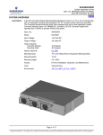
NetSure™ +24VDC to -48VDC Converter System Installation and User Instructions UM584622100 (Issue AC, July 3, 2012) SPEC. NOS. MODEL 584622100 (19” MAIN SHELF), 584622200 (19” EXPANSION SHELF) 584622300 (23” MAIN SHELF), 584622400 (23” EXPANSION SHELF) DCS48375 Business-Critical Continuity™, Emerson Network Power, and the Emerson Network Power logo are trademarks and service marks of Emerson Electric Co. NetSure™, NetSpan™, NetReach™, NetXtend™, and NetPerform™ are trademarks of Emerson Network Power, Energy Systems, North America, Inc. All other trademarks are the property of their respective owners. The products covered by this instruction manual are manufactured and/or sold by Emerson Network Power, Energy Systems, North America, Inc. The information contained in this document is subject to change without notice and may not be suitable for all applications. While every precaution has been taken to ensure the accuracy and completeness of this document, Emerson Network Power, Energy Systems, North America, Inc. assumes no responsibility and disclaims all liability for damages resulting from use of this information or for any errors or omissions. Refer to other local practices or building codes as applicable for the correct methods, tools, and materials to be used in performing procedures not specifically described in this document. This document is the property of Emerson Network Power, Energy Systems, North America, Inc. and contains confidential and proprietary information owned by Emerson Network Power, Energy Systems, North America, Inc. Any copying, use or disclosure of it without the written permission of Emerson Network Power, Energy Systems, North America, Inc. is strictly prohibited. Copyright © 2012, Emerson Network Power, Energy Systems, North America, Inc. All rights reserved throughout the world. Installation and User Instructions Spec. Nos. 584622100, 584622200, 584622300, 584622400 (Model DCS48375) UM584622100 Issue AC, July 3, 2012 TABLE OF CONTENTS CONTENTS PAGE STATIC WARNING ................................................................................................................... iii ADMONISHMENTS .................................................................................................................. iv General Safety .................................................................................................................................................... iv Voltages .............................................................................................................................................................. iv Circuit Card Handling .......................................................................................................................................... iv CHAPTER 1. DESCRIPTION AND INSTALLATION ACCEPTANCE CHECKLIST ..................1 System Description .............................................................................................................................................. 1 Installation Acceptance Checklist ........................................................................................................................ 1 CHAPTER 2. INSTALLING THE SYSTEM ................................................................................3 General Requirements ......................................................................................................................................... 3 Mounting the Shelf(s) ........................................................................................................................................... 5 Securing the Main Shelf to a Relay Rack ...................................................................................................... 5 Securing the Expansion Shelf(s) to a Relay Rack and Installing the Expansion Wiring Cover on the Main Shelf ................................................................................................................................................ 6 Installing Optional Lug Adapter Busbar Kits ........................................................................................................ 7 Installing Bullet Nose Circuit Breakers and/or Fuseholders (with TPS/TPL Fuses) ............................................ 8 Installing an Optional Bullet Nose GMT Fuse Block .......................................................................................... 10 CHAPTER 3. SETTING JUMPER AND SWITCH OPTIONS ................................................... 12 Jumper and Switch Settings on the System Interface Circuit Card ................................................................... 12 Switch S1 ..................................................................................................................................................... 12 Jumper P2 ................................................................................................................................................... 13 CHAPTER 4. MAKING ELECTRICAL CONNECTIONS .......................................................... 14 Admonishments ................................................................................................................................................. 14 Wiring Considerations ........................................................................................................................................ 14 Shelf(s) Grounding (Frame Ground) Connection ............................................................................................... 15 External Alarm, Reference, Monitoring, and Control Connections .................................................................... 16 Load Connections .............................................................................................................................................. 18 To Distribution Bus Row .............................................................................................................................. 18 To Optional Bullet Nose 6-Position GMT Fuse Block.................................................................................. 20 Expansion Shelf(s) Interconnections ................................................................................................................. 21 Installing Output Paralleling Leads .............................................................................................................. 21 FA/CBA and CAN Bus Interconnections ..................................................................................................... 22 DC Input Connections ........................................................................................................................................ 23 CHAPTER 5. INSTALLING THE CONVERTER MODULES AND INITIALLY STARTING THE SYSTEM ................................................................................................................................... 25 Installing Converter Modules.............................................................................................................................. 25 Table of Contents Page i This document is property of Emerson Network Power, Energy Systems, North America, Inc. and contains confidential and proprietary information owned by Emerson Network Power, Energy Systems, North America, Inc. Any copying, use, or disclosure of it without the written permission of Emerson Network Power, Energy Systems, North America, Inc. is strictly prohibited. UM584622100 Issue AC, July 3, 2012 Installation and User Instructions Spec. Nos. 584622100, 584622200, 584622300, 584622400 (Model DCS48375) Initially Starting and Checking System Operation .............................................................................................. 26 Initial Startup Preparation ............................................................................................................................ 26 Initially Starting the System ......................................................................................................................... 26 Checking System Status ............................................................................................................................. 26 CHAPTER 6. OPERATING PROCEDURES ............................................................................ 27 Converter Modules ............................................................................................................................................. 27 Using the Converter System with an ACU+ Controller ...................................................................................... 27 Local Indicators and Test Points ........................................................................................................................ 27 Local Indicators............................................................................................................................................ 27 Test Points ................................................................................................................................................... 28 CHAPTER 7. MAINTENANCE ................................................................................................. 29 Admonishments ................................................................................................................................................. 29 System Maintenance Procedures ...................................................................................................................... 29 CHAPTER 8. TROUBLESHOOTING AND REPAIR ................................................................ 30 Contact Information ............................................................................................................................................ 30 Admonishments ................................................................................................................................................. 30 Converter Modules ............................................................................................................................................. 30 System Troubleshooting Information ................................................................................................................. 30 Replacement Information ................................................................................................................................... 30 Replacement Procedures................................................................................................................................... 31 Replacing a Converter Module .................................................................................................................... 31 Replacing a Distribution Device ................................................................................................................... 31 Replacing the System Interface Circuit Card .............................................................................................. 34 REVISION RECORD ................................................................................................................ 36 Page ii Table of Contents This document is property of Emerson Network Power, Energy Systems, North America, Inc. and contains confidential and proprietary information owned by Emerson Network Power, Energy Systems, North America, Inc. Any copying, use, or disclosure of it without the written permission of Emerson Network Power, Energy Systems, North America, Inc. is strictly prohibited. Installation and User Instructions Spec. Nos. 584622100, 584622200, 584622300, 584622400 (Model DCS48375) UM584622100 Issue AC, July 3, 2012 STATIC WARNING The printed circuit cards used in this equipment contain static sensitive components. The warnings listed below must be observed to prevent damage to these components. Disregarding any of these warnings may result in personal injury or damage to the equipment. 1. Strictly adhere to the procedures provided in this document. 2. Before touching any static sensitive component or printed circuit card containing such a component, discharge all static electricity from yourself by wearing a wrist strap grounded through a one megohm resistor. Some wrist straps, such as Emerson Network Power Part Number 631810600, have a built-in one megohm resistor; no external resistor is necessary. Read and follow wrist strap manufacturer’s instructions outlining use of a specific wrist strap. 3. Do not touch the traces or components on a printed circuit card containing static sensitive components. Handle the printed circuit card only by the edges that do not have connector pads. 4. After removing a printed circuit card containing a static sensitive component, place the printed circuit card only on conductive or anti-static material such as conductive foam, conductive plastic, or aluminum foil. Do not use ordinary Styrofoam or ordinary plastic. 5. Store and ship static sensitive devices or printed circuit cards containing such components only in static shielding containers. 6. If necessary to repair a printed circuit card containing a static sensitive component, wear an appropriately grounded wrist strap, work on a conductive surface, use a grounded soldering iron, and use grounded test equipment. Static Warning Page iii This document is property of Emerson Network Power, Energy Systems, North America, Inc. and contains confidential and proprietary information owned by Emerson Network Power, Energy Systems, North America, Inc. Any copying, use, or disclosure of it without the written permission of Emerson Network Power, Energy Systems, North America, Inc. is strictly prohibited. UM584622100 Issue AC, July 3, 2012 Installation and User Instructions Spec. Nos. 584622100, 584622200, 584622300, 584622400 (Model DCS48375) ADMONISHMENTS GENERAL SAFETY Danger: YOU MUST FOLLOW APPROVED SAFETY PROCEDURES. Performing the following procedures may expose you to hazards. These procedures should be performed by qualified technicians familiar with the hazards associated with this type of equipment. These hazards may include shock, energy, and/or burns. To avoid these hazards: a) The tasks should be performed in the order indicated. b) Remove watches, rings, and other jewelry. c) Prior to contacting any uninsulated surface or termination, use a voltmeter to verify that no voltage or the expected voltage is present. d) Wear eye protection and use recommended tools. e) Use double insulated tools appropriately rated for the work to be performed. VOLTAGES Danger: This system operates from DC input power. All DC power sources must be completely disconnected from the branch circuit wiring used to provide power to this system before DC input connections are made. Danger: This system produces DC power. CIRCUIT CARD HANDLING Warning: Installation or removal of the circuit cards requires careful handling. Before handling any circuit card, read and follow the instructions contained on the Static Warning Page. Page iv Admonishments This document is property of Emerson Network Power, Energy Systems, North America, Inc. and contains confidential and proprietary information owned by Emerson Network Power, Energy Systems, North America, Inc. Any copying, use, or disclosure of it without the written permission of Emerson Network Power, Energy Systems, North America, Inc. is strictly prohibited. Installation and User Instructions Spec. Nos. 584622100, 584622200, 584622300, 584622400 (Model DCS48375) UM584622100 Issue AC, July 3, 2012 CHAPTER 1. DESCRIPTION AND INSTALLATION ACCEPTANCE CHECKLIST SYSTEM DESCRIPTION +24VDC to -48VDC @ up to 375A Converter System. The NetSure™ DCS48375 Converter System is comprised of a main shelf and up to two (2) expansion shelves. Each shelf provides mounting positions for up to four (4) converter modules. Each shelf also provides a 15-position distribution row (19” version) or 20-position distribution row (23” version) which accepts bullet nose circuit breakers and TPS/TLS fuseholders. A GMT fuse block option is also available. Note: Refer to SAG584622100 (System Application Guide) for additional system information. Note: Refer to UM1C24481500 (Converter Module User Instructions) for converter module information. INSTALLATION ACCEPTANCE CHECKLIST Provided below is an Installation Acceptance Checklist. This checklist helps ensure proper installation and initial operation of the system. As the procedures presented in Chapters 2 through 5 of this document are completed, check the appropriate box on this list. If the procedure is not required to be performed for your installation site, also check the box in this list to indicate that the procedure was read. When installation is done, ensure that each block in this list has been checked. Some of these procedures may have been factory performed for you. Chapter 1. Description and Installation Checklist Page 1 This document is property of Emerson Network Power, Energy Systems, North America, Inc. and contains confidential and proprietary information owned by Emerson Network Power, Energy Systems, North America, Inc. Any copying, use, or disclosure of it without the written permission of Emerson Network Power, Energy Systems, North America, Inc. is strictly prohibited. UM584622100 Issue AC, July 3, 2012 Installation and User Instructions Spec. Nos. 584622100, 584622200, 584622300, 584622400 (Model DCS48375) Note: The system is not powered up until the end of this checklist. Note: Some of these procedures may have been factory performed. Chapter 2. Installing the System Optional Wiring Access Panel Installed on Top of Shelf(s), if desired Main Shelf Secured to Relay Rack Expansion Shelf(s) Secured to Relay Rack (if furnished) and Expansion Wiring Cover installed on Main Shelf Optional Lug Adapter Busbar Kits Installed Bullet Nose Circuit Breakers Installed Bullet Nose Fuseholders and TPS/TLS Fuses Installed Optional Bullet Nose GMT Fuse Block Installed (if furnished) Chapter 3. Setting Jumper and Switch Options Jumper on System Interface Circuit Card Set Switches on System Interface Circuit Card Set Chapter 4. Making Electrical Connections Shelf(s) Grounding (Frame Ground) Connection Made External Alarm, Reference, Monitoring, and Control Connections Made Load Connections Made Expansion Shelf(s) Interconnections Made (if furnished) DC Input Connections Made Chapter 5. Installing the Converter Modules and Initially Starting the System Converter Modules Installed System Started and Checked Page 2 Chapter 1. Description and Installation Checklist This document is property of Emerson Network Power, Energy Systems, North America, Inc. and contains confidential and proprietary information owned by Emerson Network Power, Energy Systems, North America, Inc. Any copying, use, or disclosure of it without the written permission of Emerson Network Power, Energy Systems, North America, Inc. is strictly prohibited. Installation and User Instructions Spec. Nos. 584622100, 584622200, 584622300, 584622400 (Model DCS48375) UM584622100 Issue AC, July 3, 2012 CHAPTER 2. INSTALLING THE SYSTEM GENERAL REQUIREMENTS The shelf is designed for mounting in a 19-inch or 23-inch wide relay rack with 1-3/4 inch multiple drilling. The installer should be familiar with the installation requirements and techniques to be used in securing the shelf(s) to a relay rack. This product is intended only for installation in a Restricted Access Location on or above a non-combustible surface. This product must be located in a Controlled Environment with access to Craftspersons only. This product is intended for installation in Network Telecommunication Facilities (CO, vault, hut, or other environmentally controlled electronic equipment enclosure). This product is intended to be connected to the common bonding network in a Network Telecommunication Facility (CO, vault, hut, or other environmentally controlled electronic equipment enclosure). Typical industry standards recommend minimum aisle space clearance of 2'6" for the front of the relay rack and 2' for the rear of the relay rack. Converter module and mounting shelf ventilating openings must not be blocked and temperature of air entering system must not exceed rated Operating Ambient Temperature Range found in SAG584622100. Chapter 2. Installing the System Page 3 This document is property of Emerson Network Power, Energy Systems, North America, Inc. and contains confidential and proprietary information owned by Emerson Network Power, Energy Systems, North America, Inc. Any copying, use, or disclosure of it without the written permission of Emerson Network Power, Energy Systems, North America, Inc. is strictly prohibited. UM584622100 Issue AC, July 3, 2012 Installation and User Instructions Spec. Nos. 584622100, 584622200, 584622300, 584622400 (Model DCS48375) INSTALLING OPTIONAL WIRING ACCESS COVER ON TOP OF SHELF(S), IF DESIRED The optional wiring access cover is a 1U high panel that is installed on top of the shelf(s) to allow greater access to load distribution return connection points. Procedure 1) To install the optional wiring access cover, perform the procedure in Figure 2-1. Wiring Access Cover Top Panel 584622100 / 584622200 shown. 584622300 / 584622400 similar. 1. Open front door. 2. Remove top panel. 3. Install Wiring Access Cover (use same hardware removed from top panel). 4. Close front door. Figure 2-1 Installing Optional Wiring Access Cover Page 4 Chapter 2. Installing the System This document is property of Emerson Network Power, Energy Systems, North America, Inc. and contains confidential and proprietary information owned by Emerson Network Power, Energy Systems, North America, Inc. Any copying, use, or disclosure of it without the written permission of Emerson Network Power, Energy Systems, North America, Inc. is strictly prohibited. Installation and User Instructions Spec. Nos. 584622100, 584622200, 584622300, 584622400 (Model DCS48375) UM584622100 Issue AC, July 3, 2012 MOUNTING THE SHELF(S) The 584622100 and 584622200 shelves are equipped with reversible mounting angles for mounting in a standard 19-inch or 23-inch wide relay rack having 1-3/4 inch multiple drillings. The 584622300 and 584622400 shelves mount in a standard 23-inch wide relay rack having 1-3/4 inch multiple drillings. Note: Refer to the “General Requirements” section at the beginning of this chapter. Securing the Main Shelf to a Relay Rack Procedure 1) 584622100 and 584622200: Reverse the mounting angles if required to fit your relay rack. Refer to Figure 2-2. 2) Secure the shelf mounting angles to the relay rack at four (4) locations per side. Use grounding washers at one (1) location per side. Refer to Figure 2-2. Ensure the grounding washers are oriented properly to enable the teeth to dig into the mounting angle surface for a secure ground connection. 584622100 / 584622200 shown. 584622300 / 584622400 similar. Torque mounting angle to shelf connections to 20 in-lbs. Torque mounting angle to relay rack connections to 70 in-lbs. 584622100 and 584622200 Reversible Mounting Angle Figure 2-2 Reversing the Mounting Angles (if required) and Securing the Shelf to a Relay Rack Chapter 2. Installing the System Page 5 This document is property of Emerson Network Power, Energy Systems, North America, Inc. and contains confidential and proprietary information owned by Emerson Network Power, Energy Systems, North America, Inc. Any copying, use, or disclosure of it without the written permission of Emerson Network Power, Energy Systems, North America, Inc. is strictly prohibited. UM584622100 Issue AC, July 3, 2012 Installation and User Instructions Spec. Nos. 584622100, 584622200, 584622300, 584622400 (Model DCS48375) Securing the Expansion Shelf(s) to a Relay Rack and Installing the Expansion Wiring Cover on the Main Shelf SECURING AN EXPANSION SHELF TO A RELAY RACK Secure an expansion shelf to a relay rack, directly below the shelf above it, per the previous procedure. The optional 1U wiring access panel is recommended for expansion shelves to facilitate load cable connections. INSTALLING THE EXPANSION WIRING COVER ON THE MAIN SHELF PERFORM THIS PROCEDURE AFTER PARALLELING THE OUTPUTS OF BOTH SHELVES AS DESCRIBED IN THE “MAKING ELECTRICAL CONNECTIONS” CHAPTER. Procedure 1) Remove the cover shown in Figure 2-3 from the main shelf. 2) Remove the expansion wiring cover from the expansion shelf as shown in Figure 2-3. 3) On the expansion wiring cover for both the expansion shelf and the main shelf (provided loose with the expansion shelf), remove the tabs shown in Figure 2-3 so wiring can pass between the shelves. Apply the provided material along the exposed edges of the cutouts to provide protection to the wires as they are passed between shelves. 4) Make the paralleling connections as described in the “Making Electrical Connections” chapter. 5) Refer to Figure 2-3, and install the expansion wiring covers to both the main shelf and the expansion shelf. Replace this cover with the Expansion Wiring Cover Expansion Wiring Cover (supplied loose with Expansion Shelf, attach to Main Shelf) Remove these tabs at the bottom of the top shelf and at the top of the bottom shelf to allow wiring between shelves. Apply the provided material along the exposed edges of the cutouts to provide protection to the wires as they are passed between shelves. 584622100 / 584622200 shown. 584622300 / 584622400 similar. Figure 2-3 Installing the Expansion Wiring Cover on the Main Shelf Page 6 Chapter 2. Installing the System This document is property of Emerson Network Power, Energy Systems, North America, Inc. and contains confidential and proprietary information owned by Emerson Network Power, Energy Systems, North America, Inc. Any copying, use, or disclosure of it without the written permission of Emerson Network Power, Energy Systems, North America, Inc. is strictly prohibited. Installation and User Instructions Spec. Nos. 584622100, 584622200, 584622300, 584622400 (Model DCS48375) UM584622100 Issue AC, July 3, 2012 INSTALLING OPTIONAL LUG ADAPTER BUSBAR KITS Procedure 1) Refer to Figure 2-4 to install the optional lug adapter busbar kits. P/N 545404 P/N 545405 P/N 545571 1. Open the shelf’s front door. 2. Install the lug adapter busbar kits as shown. Apply anti-oxidizing compound to busbar mating surfaces before installing. 3. Torque connections to 58 in-lbs using the supplied 1/4” hardware. 4. Close the front door after wiring is complete. 584622100 / 584622200 shown. 584622300 / 584622400 similar. Top Cover Removed in Illustration for Clarity Only Figure 2-4 Installing Optional Lug Adapter Busbar Kits Chapter 2. Installing the System Page 7 This document is property of Emerson Network Power, Energy Systems, North America, Inc. and contains confidential and proprietary information owned by Emerson Network Power, Energy Systems, North America, Inc. Any copying, use, or disclosure of it without the written permission of Emerson Network Power, Energy Systems, North America, Inc. is strictly prohibited. UM584622100 Issue AC, July 3, 2012 Installation and User Instructions Spec. Nos. 584622100, 584622200, 584622300, 584622400 (Model DCS48375) INSTALLING BULLET NOSE CIRCUIT BREAKERS AND/OR FUSEHOLDERS (WITH TPS/TPL FUSES) Caution: For ambient temperatures at or below +40°C (+104°F), overcurrent devices rated 100A or greater MUST HAVE an empty mounting position between it and any other overcurrent protective device. Maximum size circuit breakers that can be used are 100A single pole, 200A double pole, and 250A triple pole. Maximum size fuse is 100A. The distribution row is rated for a maximum of 250A. For ambient temperatures between +40°C (+104°F) and +65°C (+149°F), overcurrent devices rated 60A or greater MUST HAVE an empty mounting position between it and any other overcurrent protective device. Maximum size circuit breakers that can be used are 70A single pole. No double pole or triple pole circuit breakers can be used. Maximum size fuse 70A. The distribution row is rated for a maximum of 250A. Note: Circuit breakers and/or fuses may have been factory installed for you. If so, verify their positions and sizes. Procedure 1) Open the shelf’s front door. 2) Circuit Breakers and Fuses: Ensure that a circuit breaker is in the OFF position. Orient the distribution device as shown in Figure 2-5. Insert the terminals on the rear of the distribution device into their corresponding sockets on the distribution row. Ensure the alarm contact on the back of the distribution device makes contact with the alarm terminal on the mounting circuit card. Push distribution device in firmly until fully seated in the distribution row. 3) Fuses: When all fuseholders are installed, install an appropriately sized TPS/TLS fuse in each. To do this, remove the fuse carrier from the mounted fuseholder body by pulling it straight out. Slide the fuse in place between the contacts of the fuse carrier. When done, push the fuse carrier back into the fuseholder body. Note that a polarizing key on the bottom of the carrier prevents the carrier from being inserted upside down. Verify that an 18/100 ampere alarm fuse is present in each fuseholder and that a plastic safety cover is installed on this fuse. 4) Record all circuit breaker and/or fuse sizes on the label provided. 5) Close the shelf's front door. Page 8 Chapter 2. Installing the System This document is property of Emerson Network Power, Energy Systems, North America, Inc. and contains confidential and proprietary information owned by Emerson Network Power, Energy Systems, North America, Inc. Any copying, use, or disclosure of it without the written permission of Emerson Network Power, Energy Systems, North America, Inc. is strictly prohibited. Installation and User Instructions Spec. Nos. 584622100, 584622200, 584622300, 584622400 (Model DCS48375) UM584622100 Issue AC, July 3, 2012 584622100 / 584622200 shown. 584622300 / 584622400 similar. Shorter Side to the Top Shorter Side to the Top Lettering on handle must be right side up. Insert these terminals into corresponding sockets on distribution row. Insert these terminals into corresponding sockets on distribution row. Turn off before installing. Circuit Breaker Fuseholder Assembly Longer Side to the Bottom Longer Side to the Bottom Fuseholder Body TPS/TLS Fuse Safety Cover (Replacement P/N 248898700) Fuse Carrier Fuseholder Assembly Exploded View Alarm Fuse (Replacement P/N 248610301) Polarizing Keyway Matches Key on Bottom of Fuse Carrier Fuseholder Assembly (P/N 117201) includes body & carrier, alarm fuse, and alarm fuse safety cover. Figure 2-5 Installing Bullet Nose Circuit Breakers and/or Fuseholders (with TPS/TLS Fuse) Chapter 2. Installing the System Page 9 This document is property of Emerson Network Power, Energy Systems, North America, Inc. and contains confidential and proprietary information owned by Emerson Network Power, Energy Systems, North America, Inc. Any copying, use, or disclosure of it without the written permission of Emerson Network Power, Energy Systems, North America, Inc. is strictly prohibited. UM584622100 Issue AC, July 3, 2012 Installation and User Instructions Spec. Nos. 584622100, 584622200, 584622300, 584622400 (Model DCS48375) INSTALLING AN OPTIONAL BULLET NOSE GMT FUSE BLOCK Caution: At 40°C ambient, GMT fuses greater than 10A MUST HAVE an empty mounting position between it and any other fuse. Maximum total current is 35A. Maximum GMT fuse size is 15A. At 65°C ambient, GMT fuses greater than 5A MUST HAVE an empty mounting position between it and any other fuse. Maximum total current is 21A. Maximum GMT fuse size is 10A. Refer to Figure 2-6 while performing this procedure. Procedure 1) Open the shelf’s front door. 2) Follow the steps in Figure 2-6. 3) Install an appropriately sized GMT fuse in each fuse mounting position on the GMT distribution fuse block as required. If dummy fuses are installed, first remove the dummy fuse. a) Verify that dummy fuses are installed in all unused fuse positions on the GMT distribution fuse block. b) Verify that a plastic safety cover is installed on all GMT fuses on the GMT distribution fuse block. 4) Record all fuse sizes (installed on the GMT distribution fuse block) on the label provided. 5) Close the shelf's front door. Page 10 Chapter 2. Installing the System This document is property of Emerson Network Power, Energy Systems, North America, Inc. and contains confidential and proprietary information owned by Emerson Network Power, Energy Systems, North America, Inc. Any copying, use, or disclosure of it without the written permission of Emerson Network Power, Energy Systems, North America, Inc. is strictly prohibited. Installation and User Instructions Spec. Nos. 584622100, 584622200, 584622300, 584622400 (Model DCS48375) 584622100 / 584622200 shown. 584622300 / 584622400 similar. UM584622100 Issue AC, July 3, 2012 1. Press in tabs to release lug terminal busbars for positions to be occupied by GMT Fuse Block. 2. Remove two lug terminal busbars for positions to be occupied by GMT Fuse Block. Top Cover Removed in Illustration for Clarity Only 3. Plug in GMT Fuse Block and secure at one location on the RTN bar with hardware provided. Torque to 58 in-lbs. RTN Bar Figure 2-6 Installing an Optional Bullet Nose GMT Fuse Block Chapter 2. Installing the System Page 11 This document is property of Emerson Network Power, Energy Systems, North America, Inc. and contains confidential and proprietary information owned by Emerson Network Power, Energy Systems, North America, Inc. Any copying, use, or disclosure of it without the written permission of Emerson Network Power, Energy Systems, North America, Inc. is strictly prohibited. UM584622100 Issue AC, July 3, 2012 Installation and User Instructions Spec. Nos. 584622100, 584622200, 584622300, 584622400 (Model DCS48375) CHAPTER 3. SETTING JUMPER AND SWITCH OPTIONS JUMPER AND SWITCH SETTINGS ON THE SYSTEM INTERFACE CIRCUIT CARD Perform the following procedures to verify the factory settings and/or make the required settings per your site requirements. These procedures can also be used to make adjustments on a replacement circuit card. Refer to Figure 3-1 for switch and jumper locations. Switch S1 Switch Positions 1 and 2 of S1 Selects the converter system’s output voltage as shown in Table 3-1. S1 48V 50V 52V 54V Switch 1 OFF OFF ON ON Switch 2 OFF ON OFF ON Table 3-1 Converter System Output Voltage Selection Switch Position 3 of S1 Selects the current scale for the output current test points as shown in Table 3-2. S1 1A / 1mV 400A / 50mV Switch 3 OFF ON Table 3-2 Output Current Test Points “Current Scale” Selection Switch Position 4 of S1 Selects whether converter system output voltage is controlled by the system interface circuit card (stand alone mode) or by an ACU+ as shown in Table 3-3. S1 Stand Alone Mode ACU+ Controller Mode Switch 4 OFF ON Table 3-3 Output Voltage Control Selection Page 12 Chapter 3. Setting Jumper and Switch Options This document is property of Emerson Network Power, Energy Systems, North America, Inc. and contains confidential and proprietary information owned by Emerson Network Power, Energy Systems, North America, Inc. Any copying, use, or disclosure of it without the written permission of Emerson Network Power, Energy Systems, North America, Inc. is strictly prohibited. Installation and User Instructions Spec. Nos. 584622100, 584622200, 584622300, 584622400 (Model DCS48375) UM584622100 Issue AC, July 3, 2012 Jumper P2 Jumper P2 is the CAN termination jumper. a) When in stand alone mode, the jumper P2 must be in place to ensure reliable communications. b) When an ACU+ is on the CAN bus, jumper P2 should be removed. S1 Jumper P2 Switch S1 OFF ON 4 P2 3 TB2 1 2 1 TB1 9 1 12 Inside View of Main Shelf’s Front Door Figure 3-1 System Interface Circuit Card Jumper and Switch Locations Chapter 3. Setting Jumper and Switch Options Page 13 This document is property of Emerson Network Power, Energy Systems, North America, Inc. and contains confidential and proprietary information owned by Emerson Network Power, Energy Systems, North America, Inc. Any copying, use, or disclosure of it without the written permission of Emerson Network Power, Energy Systems, North America, Inc. is strictly prohibited. UM584622100 Issue AC, July 3, 2012 Installation and User Instructions Spec. Nos. 584622100, 584622200, 584622300, 584622400 (Model DCS48375) CHAPTER 4. MAKING ELECTRICAL CONNECTIONS ADMONISHMENTS Observe the admonishments located at the beginning of this document. WIRING CONSIDERATIONS All wiring should follow the current edition of the American National Standards Institute (ANSI) approved National Fire Protection Association's (NFPA) National Electrical Code (NEC), and applicable local codes. For operation in countries where the NEC is not recognized, follow applicable codes. For recommended wire sizes, crimp lugs, alarm relay contact ratings, and general wiring information and restrictions; refer to System Application Guide SAG584622100. Refer to drawing 031110100 for lug crimping information. Refer to drawings 031110200 and 031110300 for additional lug information. Refer to Table 4-1 for supplemental lug crimping information when using the special application crimp lug / strap combination. 1 Crimp Lug Part No. Crimp Tool Required , T&B Model TBM12 or TBM15 Hydraulic Heads Color Key Die Index/ Code No. Die Cat. Number PINK 42H 15508 245393500 Burndy: YA25L-4TCG1 245393600 Burndy: YA26L-4TCG1 BLACK 45 15526 245393700 Burndy: YA27L-4TCG1 ORANGE 50 15530 Burndy: YA28L-4TCG1 PURPLE 54H 15511 YELLOW 62 15510 RED 71 15514 245393800 514872 514873 1 T & B: 256-30695-1879 Burndy: YA29L-4TCG1 T & B: 256-30695-1880 Burndy: YA31L-4TCG1 The lugs should be crimped to the specifications given in the manufacturer’s instructions furnished with the crimp tool or lug. Table 4-1 Supplemental Lug Crimping Information when using the Special Application Crimp Lug / Strap Combination Page 14 Chapter 4. Making Electrical Connections This document is property of Emerson Network Power, Energy Systems, North America, Inc. and contains confidential and proprietary information owned by Emerson Network Power, Energy Systems, North America, Inc. Any copying, use, or disclosure of it without the written permission of Emerson Network Power, Energy Systems, North America, Inc. is strictly prohibited. Installation and User Instructions Spec. Nos. 584622100, 584622200, 584622300, 584622400 (Model DCS48375) UM584622100 Issue AC, July 3, 2012 SHELF(S) GROUNDING (FRAME GROUND) CONNECTION For shelf grounding requirements, refer to the current edition of the American National Standards Institute (ANSI) approved National Fire Protection Association's (NFPA) National Electrical Code (NEC), applicable local codes, and your specific site requirements. Note: The DC return connection to this system can remain isolated from system frame and chassis (DC-I). Note: This system is suitable for installation as part of the Common Bonding Network (CBN). 1/4-20 x 0.5” studs on 5/8” center are provided for installation of a customer provided frame ground lead terminated in a 2-hole lug. Procedure 1) For shelf(s) grounding (frame ground) connection, refer to Figure 4-1. 584622100 / 584622200 shown. 584622300 / 584622400 similar. Rear Frame Ground Lead Enters Here Rear panels removed in illustration. Frame Ground * 1/4-20 x 0.5” studs on 5/8” center for installation of lead with 2-hole lug. * Torque to 84 in-lbs. Figure 4-1 Shelf(s) Grounding (Frame Ground) Connection Chapter 4. Making Electrical Connections Page 15 This document is property of Emerson Network Power, Energy Systems, North America, Inc. and contains confidential and proprietary information owned by Emerson Network Power, Energy Systems, North America, Inc. Any copying, use, or disclosure of it without the written permission of Emerson Network Power, Energy Systems, North America, Inc. is strictly prohibited. UM584622100 Issue AC, July 3, 2012 Installation and User Instructions Spec. Nos. 584622100, 584622200, 584622300, 584622400 (Model DCS48375) EXTERNAL ALARM, REFERENCE, MONITORING, AND CONTROL CONNECTIONS External alarm, reference, monitoring, and control connections are made to terminals of TB1 and TB2 located on the system interface circuit card mounted on the inside of the main shelf’s front door. Refer to Figure 4-2 for location. External FA/CBA Alarm Input: An external FA/CBA alarm signal can be connected to the system as described in the Expansion Shelf(s) Interconnections section. External Alarm Relays External alarm relays are extended to terminal block TB1 located on the system interface circuit card. Relays are energized for normal operating conditions and de-energized for an alarm condition. Low Input Voltage Alarm: Alarms if a converter module reports a low input voltage condition. A close loop circuit is provided between terminals 1 and 2 of TB1 and an open loop circuit is provided between terminals 2 and 3 of TB1 during an alarm condition. Fuse / Circuit Breaker Alarm: Alarms if any distribution fuse or circuit breaker opens. A close loop circuit is provided between terminals 4 and 5 of TB1 and an open loop circuit is provided between terminals 5 and 6 of TB1 during an alarm condition. Converter Fail Major Alarm: Alarms if more than one converter module fails (or if only one converter module is installed in the system and it fails). A close loop circuit is provided between terminals 7 and 8 of TB1 and an open loop circuit is provided between terminals 8 and 9 of TB1 during an alarm condition. Refer to the Operating Procedures chapter for alarm conditions. Converter Fail Minor Alarm: Alarms if one converter module fails. A close loop circuit is provided between terminals 10 and 11 of TB1 and an open loop circuit is provided between terminals 11 and 12 of TB1 during an alarm condition. Refer to the Operating Procedures chapter for alarm conditions. CAN Bus An ACU+ can be connected to terminals 1 (CANL) and 2 (CANH) of TB2. Output Current Signal Reference The output current signal (also provided at the output current test points on the front door of the main shelf) can be selected to be referenced to plus battery (input), referenced to minus battery (input), or not referenced as detailed below. The output current signal can be set at 1A/mV or 400A/50mV per CHAPTER 3. SETTING JUMPER AND SWITCH OPTIONS. Referenced to Plus Battery (input): Provide a jumper between terminals 4 (+BT) and 5 (-IO) of TB2. Page 16 Chapter 4. Making Electrical Connections This document is property of Emerson Network Power, Energy Systems, North America, Inc. and contains confidential and proprietary information owned by Emerson Network Power, Energy Systems, North America, Inc. Any copying, use, or disclosure of it without the written permission of Emerson Network Power, Energy Systems, North America, Inc. is strictly prohibited. Installation and User Instructions Spec. Nos. 584622100, 584622200, 584622300, 584622400 (Model DCS48375) UM584622100 Issue AC, July 3, 2012 Referenced to Minus Battery (input): Provide a jumper between terminals 3 (-BT) and 6 (+IO) of TB2. Not Referenced: Do not provide a jumper. Output Voltage Monitoring An output voltage monitoring device can be connected to terminals 7 (-VO) and 8 (+VO) of TB2. These terminals are internally paralleled with the test points provided on the front door of the main shelf. Emergency Shutdown (Estop) The converter modules can be inhibited by applying an external ground signal (24V Return) to terminal 9 of TB2. Converter modules automatically restart upon removal of the ground signal. TB2 CANH CANL -BT +BT -IO TB1 +IO -VO +VO E S T O P NC 9 1 Low Input Voltage C NO Conv Major Fuse / CB NC C NO NC C Conv Minor NO NC C NO CAN TERM P2 1 Recommended Torque is 5.0 in-lbs. 12 Recommended Torque is 5.0 in-lbs. Relays are energized for normal operating conditions and de-energized for an alarm condition. Relays are shown in the de-energized state. P2 TB2 1 TB1 9 1 12 Inside View of Main Shelf’s Front Door Figure 4-2 External Alarm, Reference, Monitoring, and Control Connections Chapter 4. Making Electrical Connections Page 17 This document is property of Emerson Network Power, Energy Systems, North America, Inc. and contains confidential and proprietary information owned by Emerson Network Power, Energy Systems, North America, Inc. Any copying, use, or disclosure of it without the written permission of Emerson Network Power, Energy Systems, North America, Inc. is strictly prohibited. UM584622100 Issue AC, July 3, 2012 Installation and User Instructions Spec. Nos. 584622100, 584622200, 584622300, 584622400 (Model DCS48375) LOAD CONNECTIONS To Distribution Bus Row 1/4-20 x 0.625” studs on 5/8” centers are provided for installation of customer provided load distribution leads terminated in 2-hole lugs. Refer to Figure 4-3. Warning: Observe correct polarity when making connections. Otherwise equipment damage may occur. Procedure 1) For load connections to the distribution bus row, refer to Figure 4-3. Page 18 Chapter 4. Making Electrical Connections This document is property of Emerson Network Power, Energy Systems, North America, Inc. and contains confidential and proprietary information owned by Emerson Network Power, Energy Systems, North America, Inc. Any copying, use, or disclosure of it without the written permission of Emerson Network Power, Energy Systems, North America, Inc. is strictly prohibited. Installation and User Instructions Spec. Nos. 584622100, 584622200, 584622300, 584622400 (Model DCS48375) Load Distribution Leads Enter Here (break tabs off shield as required) 584622100 / 584622200 shown. 584622300 / 584622400 similar. Components removed in illustration for clarity only. UM584622100 Issue AC, July 3, 2012 Return -48VDC Front Load Distribution Connections * 1/4-20 x 0.625” studs on 5/8” centers for installation of leads with 2-hole lugs. * Maximum lug width 0.625”. * Torque to 58 in-lbs. P/N 545404 Optional Busbar Adapters P/N 545571 P/N 545405 Top Cover Removed in Illustration for Clarity Only Front Figure 4-3 Load Connections to Distribution Bus Row Chapter 4. Making Electrical Connections Page 19 This document is property of Emerson Network Power, Energy Systems, North America, Inc. and contains confidential and proprietary information owned by Emerson Network Power, Energy Systems, North America, Inc. Any copying, use, or disclosure of it without the written permission of Emerson Network Power, Energy Systems, North America, Inc. is strictly prohibited. UM584622100 Issue AC, July 3, 2012 Installation and User Instructions Spec. Nos. 584622100, 584622200, 584622300, 584622400 (Model DCS48375) To Optional Bullet Nose 6-Position GMT Fuse Block Warning: Observe correct polarity when making connections. Otherwise equipment damage may occur. Procedure 1) For load connections to an optional GMT fuse block, refer to Figure 4-4. Load Return Leads Load Leads Wire Size Capacity: 26-14 AWG. Recommended Torque: 4.5 in-lbs. Figure 4-4 Load Connections to GMT Fuse Block Page 20 Chapter 4. Making Electrical Connections This document is property of Emerson Network Power, Energy Systems, North America, Inc. and contains confidential and proprietary information owned by Emerson Network Power, Energy Systems, North America, Inc. Any copying, use, or disclosure of it without the written permission of Emerson Network Power, Energy Systems, North America, Inc. is strictly prohibited. Installation and User Instructions Spec. Nos. 584622100, 584622200, 584622300, 584622400 (Model DCS48375) UM584622100 Issue AC, July 3, 2012 EXPANSION SHELF(S) INTERCONNECTIONS Installing Output Paralleling Leads Procedure 1) Perform the procedure in Figure 4-5 for each expansion shelf. Cable, lugs (P/N 144511), and labels are provided loose with the Expansion Shelf to assemble a Return and a -48V paralleling cable. 1. Cut the cables to the proper length. 2. Lug the cables (use standard brown die for 2 ga. cable). 3. Connect cables between terminals as indicated below. Torque to 58 in-lbs. 4. Re-Install Expansion Wiring Covers. (refer to procedure in the “Installing the System” chapter.) RETURN PARALLELING CABLE -48V PARALLELING CABLE 584622100 / 584622200 shown. 584622300 / 584622400 similar. Hardware provided on terminals. Expansion Wiring Covers Figure 4-5 DC Output Paralleling Interconnections Chapter 4. Making Electrical Connections Page 21 This document is property of Emerson Network Power, Energy Systems, North America, Inc. and contains confidential and proprietary information owned by Emerson Network Power, Energy Systems, North America, Inc. Any copying, use, or disclosure of it without the written permission of Emerson Network Power, Energy Systems, North America, Inc. is strictly prohibited. UM584622100 Issue AC, July 3, 2012 Installation and User Instructions Spec. Nos. 584622100, 584622200, 584622300, 584622400 (Model DCS48375) FA/CBA and CAN Bus Interconnections Procedure 1) Perform the procedure in Figure 4-6 for each expansion shelf and to connect an external FA/CBA alarm lead to this system. If there are expansion shelves, unplug the external FA/CBA lead from this connector. If there are expansion shelves, move the termination plug from connector in main shelf to same connector in bottom most expansion shelf. Connect these connectors to mating connectors in shelf above. Connect these connectors to mating connectors in shelf above. Rear Move the termination plug from connector in main shelf to same connector in bottom most expansion shelf. 584622100 / 584622200 shown. 584622300 / 584622400 similar. Plug the external FA/CBA lead from main shelf into same connector in bottom most expansion shelf. External FA/CBA connector in bottom most shelf. External FA/CBA plug terminated in butt splice connector. (12” long, 22 AWG, yellow wire) (Factory Supplied) Connect an external FA/CBA lead to the butt splice located at the end of the external FA/CBA plug assembly. Supply a voltage signal within 1V of the converter system output voltage to this lead to activate the system’s fuse alarm circuit. Figure 4-6 FA/CBA and CAN Bus Interconnections Page 22 Chapter 4. Making Electrical Connections This document is property of Emerson Network Power, Energy Systems, North America, Inc. and contains confidential and proprietary information owned by Emerson Network Power, Energy Systems, North America, Inc. Any copying, use, or disclosure of it without the written permission of Emerson Network Power, Energy Systems, North America, Inc. is strictly prohibited. Installation and User Instructions Spec. Nos. 584622100, 584622200, 584622300, 584622400 (Model DCS48375) UM584622100 Issue AC, July 3, 2012 DC INPUT CONNECTIONS 3/8-16 x 0.875” studs on 1” centers are provided for installation of customer provided DC input leads terminated in 2-hole lugs. Terminations are provided for each converter module (individual feed). Adapter busbars are provided loose with each shelf which allows two (2) converter modules to be fed by a single input. Refer to Figure 4-7. Warning: Observe correct polarity when making connections. Otherwise equipment damage will occur. Note: The DC return connection to this system can remain isolated from system frame and chassis (DC-I). Note: This system is suitable for installation as part of the Common Bonding Network (CBN). Note: Recommended DC input protective device rating is 100A for individual converter module feeds and 200A for dual converter module feeds. See SAG584622100 for additional restrictions. Procedure 1) For DC input connections, refer to Figure 4-7. 2) If using the dual converter module feed adapter busbars, install the busbars as shown in Figure 4-7. Chapter 4. Making Electrical Connections Page 23 This document is property of Emerson Network Power, Energy Systems, North America, Inc. and contains confidential and proprietary information owned by Emerson Network Power, Energy Systems, North America, Inc. Any copying, use, or disclosure of it without the written permission of Emerson Network Power, Energy Systems, North America, Inc. is strictly prohibited. UM584622100 Issue AC, July 3, 2012 Installation and User Instructions Spec. Nos. 584622100, 584622200, 584622300, 584622400 (Model DCS48375) 584622100 / 584622200 shown. 584622300 / 584622400 similar. Rear Rear panels removed in illustration. DC Input Leads Enter Here +24VDC Converter #1 (top) Converter #2 Converter #3 Converter #4 (bottom) DC Input Connections * 3/8-16 x 0.875” studs on 1” centers for installation of leads with 2-hole lugs. * Provide separate inputs for each converter. * Maximum lug width 0.812”. * Torque to 240 in-lbs. Return Converter #1 Converter #2 +24VDC Converter #1 Converter #2 Return Converter #1 (top) Converter #2 Converter #3 Converter #4 (bottom) Feed One Busbars P/Ns 552506 Dual Converter Module Feed with Adapter Busbars P/Ns 552506 Discard Extra Hardware Feed Two Rear +24VDC Converter #3 Converter #4 Return Converter #3 Converter #4 DC Input Connections * 3/8-16 x 0.875” studs on 1” centers for installation of leads with 2-hole lugs. * Provide one input for two converters. * Maximum lug width 1.156”. * Torque to 240 in-lbs. Figure 4-7 DC Input Connections Page 24 Chapter 4. Making Electrical Connections This document is property of Emerson Network Power, Energy Systems, North America, Inc. and contains confidential and proprietary information owned by Emerson Network Power, Energy Systems, North America, Inc. Any copying, use, or disclosure of it without the written permission of Emerson Network Power, Energy Systems, North America, Inc. is strictly prohibited. Installation and User Instructions Spec. Nos. 584622100, 584622200, 584622300, 584622400 (Model DCS48375) UM584622100 Issue AC, July 3, 2012 CHAPTER 5. INSTALLING THE CONVERTER MODULES AND INITIALLY STARTING THE SYSTEM INSTALLING CONVERTER MODULES The converter module is hot swappable. It can be installed with the system operating. Warning: To prevent damage to the latching mechanism, ensure the handle is in the open position when installing or removing a converter module. NEVER hold the handle in the closed position when installing a converter module into a shelf. Procedure 1) Place the module into an unoccupied mounting slot without sliding it in completely. 2) Loosen the captive screw on the module handle. Pull the handle to pivot it out of the module front panel (this will also retract the latch mechanism located at the right side of the module). Refer to Figure 5-1 for latch mechanism illustration. 3) Push the converter module completely into the shelf. 4) Push the handle into the front panel of the module. This will lock the module securely to the shelf. Tighten the captive screw on the handle. 5) Repeat the above steps for each converter module being installed in the system. 6) After the converter modules are physically installed in the mounting shelf(s), they are ready for operation immediately after power is supplied to them. Note: Handle must be open when installing or removing module. Screw Handle in Closed Position Figure 5-1 Converter Module Handle/Latch Mechanism Chapter 5. Installing the Converter Modules and Initially Starting the System Page 25 This document is property of Emerson Network Power, Energy Systems, North America, Inc. and contains confidential and proprietary information owned by Emerson Network Power, Energy Systems, North America, Inc. Any copying, use, or disclosure of it without the written permission of Emerson Network Power, Energy Systems, North America, Inc. is strictly prohibited. UM584622100 Issue AC, July 3, 2012 Installation and User Instructions Spec. Nos. 584622100, 584622200, 584622300, 584622400 (Model DCS48375) INITIALLY STARTING AND CHECKING SYSTEM OPERATION Initial Startup Preparation Ensure that all blocks for Chapters 2 through 4 in the Installation Acceptance Checklist, located in Chapter 1, have been checked. Ensure no objects block the ventilation openings on the system shelf(s). Initially Starting the System Procedure 1) Close the external disconnects or protective devices that supply input power to the system. Converter modules automatically start. 2) Open each shelf’s front door. 3) Place each distribution circuit breaker (if furnished) to the ON position. 4) Close each shelf’s front door. Checking System Status Procedure 1) Observe the status of the indicators located on the main shelf’s front door and the converter modules. If the system is operating normally, the status of these is as shown in Table 5-1. Verify there are no external alarms. Component Main Shelf Front Door Converter Modules Indicator Normal State Circuit Breaker or Fuse Open (Red LED) Off Input Voltage OK (Green LED) On Converter Major (Red LED) Off Converter Minor (Yellow LED) Off Power (Green) On Protection (Yellow) Off Fault (Red) Off Table 5-1 Status and Alarm Indicators Page 26 Chapter 5. Installing the Converter Modules and Initially Starting the System This document is property of Emerson Network Power, Energy Systems, North America, Inc. and contains confidential and proprietary information owned by Emerson Network Power, Energy Systems, North America, Inc. Any copying, use, or disclosure of it without the written permission of Emerson Network Power, Energy Systems, North America, Inc. is strictly prohibited. Installation and User Instructions Spec. Nos. 584622100, 584622200, 584622300, 584622400 (Model DCS48375) UM584622100 Issue AC, July 3, 2012 CHAPTER 6. OPERATING PROCEDURES CONVERTER MODULES Refer to UM1C24481500 (Converter Module User Instructions) for converter module operation instructions. USING THE CONVERTER SYSTEM WITH AN ACU+ CONTROLLER The following outlines the steps to set-up the converter system to be used with an ACU+ controller. Refer to the ACU+ Controller User Instructions (UM1M820BNA) for ACU+ operation. Set switch position 4 of S1 to the “ON” position. See Figure 3-1. Remove (and store) Jumper P2. See Figure 3-1. Connect terminal 1 (CANL) and 2 (CANH) of TB2 to the CAN bus the ACU+ resides on. See Figure 4-2. Note: The converter system must be the last device on the CAN bus to function properly. Note: If the converter system is used with control/monitoring via an ACU+ controller and the converter input is powered through a distribution device in the host system, the ACU+ controller should not be set up to calculate battery current. If battery current measurement via the ACU+ is desired, the host system must measure battery current with a battery shunt. LOCAL INDICATORS AND TEST POINTS Refer to the Converter Module User Instructions (UM1C24481500) for descriptions of the local indicators located on the converter modules. Refer to this section for descriptions of the local indicators and test points located on the main shelf’s front door. Local Indicators The following local indicators are provided on the front door of the main shelf. Refer to Figure 6-1. a) Circuit Breaker or Fuse Open (Red LED): Illuminates red if any distribution fuse or circuit breaker in the system opens. b) Input Voltage OK (Green LED): Illuminates green when all converter modules report input voltage is OK. This indicator is off if any converter module reports a low input voltage condition. Chapter 6. Operating Procedures Page 27 This document is property of Emerson Network Power, Energy Systems, North America, Inc. and contains confidential and proprietary information owned by Emerson Network Power, Energy Systems, North America, Inc. Any copying, use, or disclosure of it without the written permission of Emerson Network Power, Energy Systems, North America, Inc. is strictly prohibited. UM584622100 Issue AC, July 3, 2012 Installation and User Instructions Spec. Nos. 584622100, 584622200, 584622300, 584622400 (Model DCS48375) c) Converter Major (Red LED): Illuminates red if more than one converter module fails (or if only one converter module is installed in the system and it fails). Failure conditions are as stated in d) below. d) Converter Minor (Yellow LED): Illuminates yellow if one converter module fails. Failure conditions are as follows. A converter module reports a high voltage shutdown condition (HVSD). A converter module reports a fan failure. A converter module reports an EEPROM failure. A converter module reports a converter failure. A converter module reports a low input voltage condition. A converter module reports a high temperature condition. A converter module reports a thermal derating condition. Test Points The following test points are provided on the front door of the main shelf. Refer to Figure 6-1. a) Output Voltage (+, -): Provided for measuring system output voltage. b) Output Current (+, -): Provided for measuring system output current. Scale is User selectable for 400A/50mV or 1A/1mV. Current measurement is User selectable to be referenced to plus battery, minus battery, or no reference. See CHAPTER 3. SETTING JUMPER AND SWITCH OPTIONS. 584622100 shown. 584622300 similar. CIRCUIT BREAKER OR FUSE OPEN INPUT VOLTAGE OK CHECK SWITCH S1 SETTING FOR CURRENT SCALE OUTPUT CURRENT OUTPUT VOLTAGE CONVERTER MAJOR CONVERTER MINOR Front of Main Shelf Figure 6-1 Local Indicators and Test Points Page 28 Chapter 6. Operating Procedures This document is property of Emerson Network Power, Energy Systems, North America, Inc. and contains confidential and proprietary information owned by Emerson Network Power, Energy Systems, North America, Inc. Any copying, use, or disclosure of it without the written permission of Emerson Network Power, Energy Systems, North America, Inc. is strictly prohibited. Installation and User Instructions Spec. Nos. 584622100, 584622200, 584622300, 584622400 (Model DCS48375) UM584622100 Issue AC, July 3, 2012 CHAPTER 7. MAINTENANCE ADMONISHMENTS Observe the admonishments located at the beginning of this document. SYSTEM MAINTENANCE PROCEDURES It is recommended to perform and record the maintenance procedures listed in Table 7-1 every 6-months to ensure continual system operation. The table references specific chapters in this document that help in performing these procedures. PROCEDURE REFERENCED IN Check ventilation openings for obstructions such as dust, papers, manuals, etc. -- Inspect and tighten all installer's connections. COMPLETED (√) Chapter 4. Making Electrical Connections. Note: This table may be reproduced as necessary to record and document system performance. Table 7-1 Maintenance Procedures to be Performed at 6-Month Intervals Chapter 7. Maintenance Page 29 This document is property of Emerson Network Power, Energy Systems, North America, Inc. and contains confidential and proprietary information owned by Emerson Network Power, Energy Systems, North America, Inc. Any copying, use, or disclosure of it without the written permission of Emerson Network Power, Energy Systems, North America, Inc. is strictly prohibited. UM584622100 Issue AC, July 3, 2012 Installation and User Instructions Spec. Nos. 584622100, 584622200, 584622300, 584622400 (Model DCS48375) CHAPTER 8. TROUBLESHOOTING AND REPAIR CONTACT INFORMATION Support contact information is provided on the inside of the back cover of this document. ADMONISHMENTS Observe the admonishments located at the beginning of this document. CONVERTER MODULES Refer to UM1C24481500 (Converter Module User Instructions) for converter module troubleshooting and repair instructions. SYSTEM TROUBLESHOOTING INFORMATION This system is designed for ease in troubleshooting and repair. The various indicators as described in CHAPTER 6. OPERATING PROCEDURES and in the Converter Module User Instructions (UM1C24481500) are designed to isolate failure to a specific element. Once the faulty element has been identified, refer to “Replacement Information” and "Replacement Procedures" in this chapter. Clearing a Converter Fail Alarm after Removing a Converter Module If a converter module is removed from the system, a converter fail alarm is generated. If the converter module will not be replaced, the alarm should be cleared as described in the following procedure. Procedure 1) Momentarily push the “Update Converter Inventory” button located on the inside of the main shelf’s front door. Refer to Figure 3-1 for location. REPLACEMENT INFORMATION When a trouble symptom is localized to a faulty converter module, the converter module should be replaced in its entirety. Other than a converter module fan replacement, no attempt should be made to troubleshoot or repair individual components on any converter module. Refer to SAG584622100 (System Application Guide) for replacement part numbers. Page 30 Chapter 8. Troubleshooting and Repair This document is property of Emerson Network Power, Energy Systems, North America, Inc. and contains confidential and proprietary information owned by Emerson Network Power, Energy Systems, North America, Inc. Any copying, use, or disclosure of it without the written permission of Emerson Network Power, Energy Systems, North America, Inc. is strictly prohibited. Installation and User Instructions Spec. Nos. 584622100, 584622200, 584622300, 584622400 (Model DCS48375) UM584622100 Issue AC, July 3, 2012 REPLACEMENT PROCEDURES Replacing a Converter Module Refer to the Converter Module User Instructions (UM1C24481500) for a converter module replacement procedure. Refer also to System Troubleshooting Information in this chapter to clear a converter fail alarm after removing a converter module. Replacing a Distribution Device General Replace distribution devices with the same type and rating, or equivalent. Refer to SAG584622100 (System Application Guide) for part numbers. Distribution Fuse “Alarm Fuse” Replacement If a distribution fuse opens, the associated alarm fuse opens. Replace the distribution fuse before replacing the alarm fuse. Procedure 1) An alarm fuse is removed by pulling it straight out of the fuseholder. If the alarm fuse is located in a modular fuse carrier, hold the fuse carrier in place with your thumb while pulling on the alarm fuse to prevent the entire carrier from inadvertently being pulled out. 2) Safety fuse covers are provided for all Bussmann GMT type fuses installed in the system. These covers snap onto the fuses and provide protection from exposed electrical terminations when a fuse opens. Insure that the safety fuse cover is installed after replacing a fuse. Refer to Figure 8-1 for installation details. Safety Cover P/N 248898700 (GMT-X) Safety Cover P/N 102774 (GMT-Y) Figure 8-1 Installation of Safety Fuse Covers Chapter 8. Troubleshooting and Repair Page 31 This document is property of Emerson Network Power, Energy Systems, North America, Inc. and contains confidential and proprietary information owned by Emerson Network Power, Energy Systems, North America, Inc. Any copying, use, or disclosure of it without the written permission of Emerson Network Power, Energy Systems, North America, Inc. is strictly prohibited. UM584622100 Issue AC, July 3, 2012 Installation and User Instructions Spec. Nos. 584622100, 584622200, 584622300, 584622400 (Model DCS48375) Replacing a TPS/TLS Fuse Note: Refer to Figure 2-5 as this procedure is performed. Procedure 1) Open the shelf’s front door. 2) Remove the fuse carrier from the mounted fuseholder body by pulling it straight out. 3) Remove the open fuse from the fuse carrier and replace it with the same type and rating, or equivalent. 4) Replace the alarm fuse located in the front of the fuse carrier with the same type and rating, or equivalent. Ensure that a plastic safety cover is installed on the alarm fuse. 5) Push the fuse carrier securely back into the mounted fuseholder body. Note that a polarizing key on the bottom of the carrier prevents the carrier from being inserted upside down. 6) Verify there are no alarms active. 7) Close the shelf’s front door. Page 32 Chapter 8. Troubleshooting and Repair This document is property of Emerson Network Power, Energy Systems, North America, Inc. and contains confidential and proprietary information owned by Emerson Network Power, Energy Systems, North America, Inc. Any copying, use, or disclosure of it without the written permission of Emerson Network Power, Energy Systems, North America, Inc. is strictly prohibited. Installation and User Instructions Spec. Nos. 584622100, 584622200, 584622300, 584622400 (Model DCS48375) UM584622100 Issue AC, July 3, 2012 Replacing a Bullet Nose Circuit Breaker or Fuseholder Note: Refer to Figure 2-5 as this procedure is performed. Procedure 1) Open the shelf’s front door. 2) Circuit Breaker: Operate a defective circuit breaker to the OFF position. Fuseholder: Remove the fuse carrier from the mounted fuseholder body by pulling it straight out. 3) Gently rock the defective circuit breaker or fuseholder up and down while pulling firmly outward until the circuit breaker or fuseholder is free from the distribution row. 4) Circuit Breaker: Ensure that the circuit breaker is in the OFF position, and is of the correct rating. 5) Orient the distribution device as shown in Figure 2-5. Insert the terminals on the rear of the distribution device into their corresponding sockets on the distribution row. Ensure the alarm contact on the back of the distribution device makes contact with the alarm terminal on the mounting circuit card. Push distribution device in firmly until fully seated in the distribution row. 6) Circuit Breaker: Operate the replacement circuit breaker to the ON position. Fuseholder: Push the fuse carrier securely back into the mounted fuseholder body. Note that a polarizing key on the bottom of the carrier prevents the carrier from being inserted upside down. 7) Verify there are no alarms active. 8) Close the shelf’s front door. Chapter 8. Troubleshooting and Repair Page 33 This document is property of Emerson Network Power, Energy Systems, North America, Inc. and contains confidential and proprietary information owned by Emerson Network Power, Energy Systems, North America, Inc. Any copying, use, or disclosure of it without the written permission of Emerson Network Power, Energy Systems, North America, Inc. is strictly prohibited. UM584622100 Issue AC, July 3, 2012 Installation and User Instructions Spec. Nos. 584622100, 584622200, 584622300, 584622400 (Model DCS48375) Replacing the System Interface Circuit Card Warning: The system interface circuit card contains static-sensitive devices. Read the Static Warning at the front of this document before performing the following procedure. Caution: When performing any step in this procedure that requires removal or installation of hardware, use caution to ensure no hardware is dropped and left inside the cabinet; otherwise service interruption or equipment damage may occur. Note: When performing any step in this procedure that requires removal of existing hardware, retain all hardware for use in subsequent steps. Note: Refer to Figure 8-2 as this procedure is performed. Procedure 1) Refer to the Static Warning and Admonishments at the beginning of this document before performing this procedure. 2) Performing this procedure may activate external alarms. Do one of the following. If possible, disable these alarms. If these alarms cannot be easily disabled, notify the appropriate personnel to disregard any future alarms associated with this system while the procedure is being performed. 3) Open the main shelf’s front door. Warning: Damage to the circuit card may result if the next step is not followed. 4) Connect an approved grounding strap to your wrist. Attach the other end to a suitable ground. 5) On the replacement circuit card, set the switches and jumper to match the existing circuit card settings. Refer to Figure 3-1. 6) Transfer any jumpers on terminal block TB2 of the existing circuit card to the replacement circuit card. Refer to Figure 4-2. 7) Carefully label any wires connected to terminal blocks TB1 and TB2 on the existing circuit card. These wires must be connected to the same terminals on the replacement circuit card. Refer to Figure 4-2. 8) Remove the external wiring from terminal blocks TB1 and TB2. 9) Unplug the connector plugged into the circuit card. 10) Remove the screws securing the cover over the System Interface Circuit Card and remove the cover and circuit card. 11) Position the replacement circuit card over its mounting position and replace the cover. Secure the cover and circuit card with the screws previously removed. Page 34 Chapter 8. Troubleshooting and Repair This document is property of Emerson Network Power, Energy Systems, North America, Inc. and contains confidential and proprietary information owned by Emerson Network Power, Energy Systems, North America, Inc. Any copying, use, or disclosure of it without the written permission of Emerson Network Power, Energy Systems, North America, Inc. is strictly prohibited. Installation and User Instructions Spec. Nos. 584622100, 584622200, 584622300, 584622400 (Model DCS48375) UM584622100 Issue AC, July 3, 2012 12) Reconnect the external wiring to the correct terminals on terminal blocks TB1 and TB2. 13) Plug the connector removed from the old circuit card into the same position on the replacement circuit card. 14) Remove the grounding wrist strap. 15) Enable the external alarms, or notify appropriate personnel that this procedure is finished. 16) Ensure that there are no local or remote alarms active on the system. 17) Close the shelf’s front door. System Interface Circuit Card Insid e Vie w of Main Shel f’s Fron t Door Figure 8-2 Replacing the System Interface Circuit Card Chapter 8. Troubleshooting and Repair Page 35 This document is property of Emerson Network Power, Energy Systems, North America, Inc. and contains confidential and proprietary information owned by Emerson Network Power, Energy Systems, North America, Inc. Any copying, use, or disclosure of it without the written permission of Emerson Network Power, Energy Systems, North America, Inc. is strictly prohibited. UM584622100 Issue AC, July 3, 2012 Installation and User Instructions Spec. Nos. 584622100, 584622200, 584622300, 584622400 (Model DCS48375) REVISION RECORD Issue Change Number (ECO) AA LLP215922 New AB LLP216279 Optional external FA/CBA plug assembly added. AC LLP217215 Added 584622300 and 584622400. Page 36 Description of Change Revision Record This document is property of Emerson Network Power, Energy Systems, North America, Inc. and contains confidential and proprietary information owned by Emerson Network Power, Energy Systems, North America, Inc. Any copying, use, or disclosure of it without the written permission of Emerson Network Power, Energy Systems, North America, Inc. is strictly prohibited. NetPerform™ Optimization Services At Emerson Network Power, we understand the importance of reliable equipment – it’s critical to both your business and your bottom line. That is why we offer a wide array of services to meet all of your network infrastructure needs. Technical Support Email [email protected] [email protected] Phone 1.800.800.5260 Answers technical product and system questions; determines status of warranties and contractual agreements for repair. Services - Design, Deployment & Optimization Email [email protected] Phone 1.800.800.1280, option 7 FreedomCare Secure.EmersonNetworkPower.com Provides quotes and bid responses, order placement and scheduling for design, and deployment and optimization services. Download service & maintenance reports online. Spare Parts Email [email protected] [email protected] Phone 1.800.800.1280, option 5 Pricing and PO processing of spare parts, including but not limited to breakers, cables, fuses, rectifier fans, misc. breaker and fuse panels, enclosure fans, doors & switches, etc. DC Power Depot Repair Email [email protected] Phone 1.800.800.1280, option 6 Creates and processes RMAs, determines lead times and pricing, provides repair shipping information and status. DC Power Product Training Email Phone [email protected] Requests for quotes, order placement and scheduling. 1.800.800.1280, option 8 For More Information To learn more about service offerings from Emerson Network Power, please contact your sales representative, call 1-800-800-1280 option 7, email [email protected] or visit www.EmersonNetworkPower.com/EnergySystems.