1
0.
®
Dolby DP600 Program
Optimizer Manual
Issue 2
Part Number 91963
Dolby Laboratories, Inc.
Corporate Headquarters
Dolby Laboratories, Inc.
100 Potrero Avenue
San Francisco, CA 94103‐4813 USA
Telephone 415‐558‐0200
Fax 415‐863‐1373
www.dolby.com
European Headquarters
Dolby Laboratories, Inc.
Wootton Bassett
Wiltshire SN4 8QJ England
Telephone 44‐1793‐842100
Fax 44‐1793‐842101
DISCLAIMER OF WARRANTIES:
EQUIPMENT MANUFACTURED BY DOLBY LABORATORIES IS WARRANTED AGAINST DEFECTS IN MATERIALS AND WORKMANSHIP FOR A PERIOD OF ONE YEAR FROM THE DATE OF PURCHASE. THERE ARE NO OTHER EXPRESS OR IMPLIED WARRANTIES AND NO WARRANTY OF MERCHANTABILITY OR FITNESS FOR A PARTICULAR PURPOSE, OR OF NONINFRINGEMENT OF THIRD‐PARTY RIGHTS (INCLUDING, BUT NOT LIMITED TO, COPYRIGHT AND PATENT RIGHTS).
LIMITATION OF LIABILITY: IT IS UNDERSTOOD AND AGREED THAT DOLBY LABORATORIES’ LIABILITY, WHETHER IN CONTRACT, IN TORT, UNDER ANY WARRANTY, IN NEGLIGENCE, OR OTHERWISE, SHALL NOT EXCEED THE COST OF REPAIR OR REPLACEMENT OF THE DEFECTIVE COMPONENTS OR ACCUSED INFRINGING DEVICES, AND UNDER NO CIRCUMSTANCES SHALL DOLBY LABORATORIES BE LIABLE FOR INCIDENTAL, SPECIAL, DIRECT, INDIRECT, OR CONSEQUENTIAL DAMAGES (INCLUDING, BUT NOT LIMITED TO, DAMAGE TO SOFTWARE OR RECORDED AUDIO OR VISUAL MATERIAL), COST OF DEFENSE, OR LOSS OF USE, REVENUE, OR PROFIT, EVEN IF DOLBY LABORATORIES OR ITS AGENTS HAVE BEEN ADVISED, ORALLY OR IN WRITING, OF THE POSSIBILITY OF SUCH DAMAGES.
Dolby, Pro Logic, and the double‐D symbol are registered trademarks of Dolby Laboratories. Part Number 91963
Dialogue Intelligence is a trademark of Dolby Laboratories. S08/18709/19636 All other trademarks remain the property of their respective owners. Issue 2 © 2008 Dolby Laboratories, All rights reserved. ii
Dolby® DP600 Program Optimizer Manual
Regulatory Notices
FCC
NOTE: This equipment has been tested and found to comply with the limits for a Class A digital device, pursuant to Part 15 of the FCC Rules. These limits are designed to provide reasonable protection against harmful interference when the equipment is operated in a commercial environment. This equipment generates, uses, and can radiate radio frequency energy and, if not installed and used in accordance with this instruction manual, may cause harmful interference to radio communications. Operation of this equipment in a residential area is likely to cause harmful interference in which case the user will be required to correct the interference at his own expense.
Canada
This Class A digital apparatus complies with Canadian ICES‐003.
EU/EMC
This is a class A product. In a domestic environment this product may cause radio interference in which case the user may be required to take adequate measures.
Important Safety Instructions
1. CAUTION: Troubleshooting must be performed by a trained technician. To reduce the risk of electric shock, do not attempt to service this equipment unless you are qualified to do so.
2. Do not defeat the safety purpose of the polarized or grounding‐type plug. A polarized plug has two blades with one wider than the other. A grounding‐type plug has two blades and a third grounding prong. The wide blade or the third prong is provided for your safety. If the provided plug does not fit into your outlet, consult an electrician for replacement of the obsolete outlet.
3. This apparatus must be earthed (grounded) by connecting to a correctly wired and earthed power outlet.
4. Ensure that your mains supply is in the correct range for the input power requirement of the unit.
5. In order to reduce the risk of electrical shock, the power cord must be disconnected when the power supply assembly is removed.
6. This equipment is designed to mount in a suitably ventilated 19” rack; ensure that any ventilation slots in the unit are not blocked or covered.
7. CAUTION: This equipment contains a lithium battery. Danger of explosion if the battery is incorrectly replaced. Replace only with the same or equivalent type. Do not disassemble, crush, puncture, short external contacts, or dispose of in fire or water. Dispose of the used battery in accordance with local law.
8. The mains power disconnect device for this unit is the plug‐in mains cord rather than a power switch. The mains cord must remain readily accessible for disconnecting mains power.
Dolby® DP600 Program Optimizer Manual
iii
Regulatory Notices
9. To avoid exposure to dangerous voltages and to avoid damage to the unit, do not connect the rear panel Ethernet port to telephone circuits.
10. As the colours of the cores in the mains lead may not correspond with the coloured markings identifying the terminals in your plug, proceed as follows:
•
The green and yellow core must be connected to the terminal in the plug identified by the letter E, or by the earth symbol , or coloured green, or green and yellow.
•
The blue core must be connected to the terminal marked with the letter N or coloured black.
•
The brown core must be connected to the terminal marked with the letter L or coloured red.
11. This apparatus must be earthed.
WEEE
PRODUCT END‐OF‐LIFE INFORMATION
This product was designed and built by Dolby Laboratories to provide many years of service, and is backed by our commitment to provide high‐quality support. When it eventually reaches the end of its serviceable life, it should be disposed of in accordance with local or national legislation.
For current information please visit our website at: www.dolby.com/environment.
iv
Dolby® DP600 Program Optimizer Manual
Regulatory Notices
IMPORTANT SAFETY NOTICE
This unit complies with safety standard EN60950-1 as appropriate. The unit shall not be exposed to dripping or splashing and no objects filled with
liquids, such as coffee cups, shall be placed on the equipment. To ensure safe operation and to guard against potential shock hazard or risk of fire, the
following must be observed:
o Ensure that your mains supply is in the correct range for the input power requirement of the unit.
o Ensure fuses fitted are the correct rating and type as marked on the unit.
GB
o The unit must be earthed by connecting to a correctly wired and earthed power outlet.
o The power cord supplied with this unit must be wired as follows:
Live—Brown
Neutral—Blue
Earth—Green/Yellow
IMPORTANT – NOTE DE SECURITE
Ce materiel est conforme à la norme EN60950-1. Ne pas exposer cet appareil aux éclaboussures ou aux gouttes de liquide. Ne pas poser d'objets remplis
de liquide, tels que des tasses de café, sur l'appareil. Pour vous assurer d'un fonctionnement sans danger et de prévenir tout choc électrique ou tout
risque d'incendie, veillez à observer les recommandations suivantes.
o Le selecteur de tension doit être placé sur la valeur correspondante à votre alimentation réseau.
o Les fusibles doivent correspondre à la valeur indiquée sur le materiel.
F
o Le materiel doit être correctement relié à la terre.
o Le cordon secteur livré avec le materiel doit être cablé de la manière suivante:
Phase—Brun
Neutre—Bleu
Terre—Vert/Jaune
WICHTIGER SICHERHEITSHINWEIS
Dieses Gerät entspricht der Sicherheitsnorm EN60950-1. Das Gerät darf nicht mit Flüssigkeiten (Spritzwasser usw.) in Berührung kommen; stellen Sie
keine Gefäße, z.B. Kaffeetassen, auf das Gerät. Für das sichere Funktionieren des Gerätes und zur Unfallverhütung (elektrischer Schlag, Feuer) sind die
folgenden Regeln unbedingt einzuhalten:
o Der Spannungswähler muß auf Ihre Netzspannung eingestellt sein.
o Die Sicherungen müssen in Typ und Stromwert mit den Angaben auf dem Gerät übereinstimmen.
o Die Erdung des Gerätes muß über eine geerdete Steckdose gewährleistet sein.
D
o Das mitgelieferte Netzkabel muß wie folgt verdrahtet werden:
Phase—braun
Nulleiter—blau
Erde—grün/gelb
NORME DI SICUREZZA – IMPORTANTE
Questa apparecchiatura è stata costruita in accordo alle norme di sicurezza EN60950-1. Il prodotto non deve essere sottoposto a schizzi, spruzzi e
gocciolamenti, e nessun tipo di oggetto riempito con liquidi, come ad esempio tazze di caffè, deve essere appoggiato sul dispositivo. Per una perfetta
sicurezza ed al fine di evitare eventuali rischi di scossa êlettrica o d'incendio vanno osservate le seguenti misure di sicurezza:
o Assicurarsi che il selettore di cambio tensione sia posizionato sul valore corretto.
o Assicurarsi che la portata ed il tipo di fusibili siano quelli prescritti dalla casa costruttrice.
o L'apparecchiatura deve avere un collegamento di messa a terra ben eseguito; anche la connessione rete deve
I
avere un collegamento a terra.
o Il cavo di alimentazione a corredo dell'apparecchiatura deve essere collegato come segue:
Filo tensione—Marrone
Neutro—Blu
Massa—Verde/Giallo
AVISO IMPORTANTE DE SEGURIDAD
Esta unidad cumple con la norma de seguridad EN60950-1. La unidad no debe ser expuesta a goteos o salpicaduras y no deben colocarse sobre el equipo
recipientes con liquidos, como tazas de cafe. Para asegurarse un funcionamiento seguro y prevenir cualquier posible peligro de descarga o riesgo de
incendio, se han de observar las siguientes precauciones:
o Asegúrese que el selector de tensión esté ajustado a la tensión correcta para su alimentación.
o Asegúrese que los fusibles colocados son del tipo y valor correctos, tal como se marca en la unidad.
E
o La unidad debe ser puesta a tierra, conectándola a un conector de red correctamente cableado y puesto a tierra.
o El cable de red suministrado con esta unidad, debe ser cableado como sigue:
Vivo—Marrón
Neutro—Azul
Tierra—Verde/Amarillo
VIKTIGA SÄKERHETSÅTGÄRDER!
Denna enhet uppfyller säkerhetsstandard EN60950-1. Enheten får ej utsättas för yttre åverkan samt föremål innehållande vätska, såsom kaffemuggar,
får ej placeras på utrustningen. För att garantera säkerheten och gardera mot eventuell elchock eller brandrisk, måste följande observeras:
o Kontrollera att spänningsväljaren är inställd på korrekt nätspänning.
o Konrollera att säkringarna är av rätt typ och för rätt strömstyrka så som anvisningarna på enheten föreskriver.
o Enheten måste vara jordad genom anslutning till ett korrekt kopplat och jordat el-uttag.
S
o El-sladden som medföljer denna enhet måste kopplas enligt foljande:
Fas—Brun
Neutral—Blå
Jord—Grön/Gul
BELANGRIJK VEILIGHEIDS-VOORSCHRIFT:
Deze unit voldoet aan de EN60950-1 veiligheids-standaards. Dit apparaat mag niet worden blootgesteld aan vocht. Vanwege het risico dat er druppels
in het apparaat vallen, dient u er geen vloeistoffen in bekers op te plaatsen. Voor een veilig gebruik en om het gevaar van electrische schokken en het
risico van brand te vermijden, dienen de volgende regels in acht te worden genomen:
o Controleer of de spanningscaroussel op het juiste Voltage staat.
o Gebruik alleen zekeringen van de aangegeven typen en waarden.
NL
o Aansluiting van de unit alleen aan een geaarde wandcontactdoos.
o De netkabel die met de unit wordt geleverd, moet als volgt worden aangesloten:
Fase—Bruin
Nul—Blauw
Aarde—Groen/Geel
Dolby® DP600 Program Optimizer Manual
v
Table of Contents
Chapter 1 Introduction
1.1
1.2
1.3
1.4
1.5
Work Flow Integration.........................................................................................................3
Work Flow Flexibility and Ease of Use ...............................................................................3
Applications ........................................................................................................................4
Supported Media Formats and Audio Types ......................................................................4
DP600 Front Panel .............................................................................................................5
1.5.1 Touch Screen User Interface ...................................................................................5
1.5.2 CD/DVD Drive..........................................................................................................5
1.5.3 System Reset and Display Controls ........................................................................6
1.5.4 Power Supply Indicators ..........................................................................................6
1.5.5 Internal Drive Indicators ...........................................................................................6
1.5.6 USB 2.0 Port ............................................................................................................7
1.6 DP600 Rear Panel..............................................................................................................8
Chapter 2 Using the DP600
2.1 Installing the DP600 Hardware ...........................................................................................9
2.2 Starting the System for the First Time ..............................................................................10
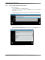
2.2.1 DP600 Home Screen .............................................................................................20
2.2.2 Using the System Screen ......................................................................................21
2.3 Using the DP600 Remote Client Software........................................................................27
2.3.1 Understanding Work Orders ..................................................................................27
2.3.2 Running the DP600 Client .....................................................................................29
2.3.3 DP600 Client Home Screen...................................................................................30
2.4 Creating a Work Order .....................................................................................................31
Chapter 3 System Maintenance
3.1 Maintaining the DP600 Hard Drives .................................................................................43
3.1.1 Replacing a Drive...................................................................................................44
3.1.2 Rebuilding a Drive..................................................................................................49
3.2 Replacing a DP600 Power Supply ...................................................................................51
3.3 Upgrading/Installing the DP600 Software.........................................................................55
Appendix A Setting Up a Shared Folder
and Entering a Path
A.1 Setting Up a Shared Folder ..............................................................................................57
A.2 Entering a Path ................................................................................................................58
A.3 Entering a Source Path ....................................................................................................58
A.3.1 Entering a URL to Specify a Path ..........................................................................59
A.3.2 Browsing to a Location to Specify a Path ..............................................................60
A.3.3 Selecting a Bookmark to Specify a Path................................................................64
A.4 Entering a Destination Path ..............................................................................................65
Dolby® DP600 Program Optimizer Manual
vii
Table of Contents
Appendix B DP600 Program Optimizer Detailed Profile Descriptions
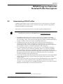
B.1 Understanding DP600 Profiles .........................................................................................67
B.2 Profile Descriptions...........................................................................................................69
Index.............................................................................................................................. 91
viii
Dolby® DP600 Program Optimizer Manual
List of Figures
Figure 1-1
Figure 1-2
Figure 1-3
Figure 1-4
Figure 1-5
Figure 2-1
Figure 2-2
Figure 2-3
Figure 2-4
Figure 2-5
Figure 2-6
Figure 2-7
Figure 2-8
Figure 2-9
Figure 2-10
Figure 2-11
Figure 2-12
Figure 2-13
Figure 2-14
Figure 2-15
Figure 2-16
Figure 2-17
Figure 2-18
Figure 2-19
Figure 2-20
Figure 2-21
Figure 2-22
Figure 2-23
Figure 2-24
Figure 2-25
Figure 2-26
Figure 2-27
Figure 2-28
Figure 2-29
Figure 2-30
Figure 2-31
Figure 2-32
Figure 2-33
Figure 2-34
Figure 2-35
Figure 2-36
Figure 2-37
Figure 2-38
Figure 2-39
Coded Audio with Metadata Analysis and Correction ........................................................... 2
Audio Analysis and Correction for Audio Types Without Metadata ....................................... 2
DP600 Front Panel ................................................................................................................ 5
DP600 CD/DVD Drive (Behind Touch Screen Door)............................................................. 5
DP600 Rear Panel................................................................................................................. 8
Connect DP600 Keyboard (Front-Panel connection) ............................................................ 9
Connect DP600 to Network ................................................................................................... 9
DP600 Welcome! Screen .................................................................................................... 10
Network Screen ................................................................................................................... 11
Enter Gateway Address Number Pad Screen ..................................................................... 11
Date & Time Screen ............................................................................................................ 12
Set Server Date/Time Screen.............................................................................................. 12
Select Region Screen.......................................................................................................... 13
Select City or Zone Screen.................................................................................................. 13
License Agreement Screen ................................................................................................. 14
License Screen.................................................................................................................... 14
Select Product Licensing on DolbySupport Home Page ..................................................... 15
Get New License File Page ................................................................................................. 15
Product Registered Page .................................................................................................... 16
Upgrade Serial Number....................................................................................................... 17
Upgrade Appears Under Previous Upgrades ...................................................................... 17
License Confirmation Prompt .............................................................................................. 18
Finished! Screen.................................................................................................................. 19
DP600 Front-Panel Home Screen....................................................................................... 20
System Screen .................................................................................................................... 21
Software Information Screen ............................................................................................... 21
Upgrade Screen .................................................................................................................. 22
License Upgrade Screen ..................................................................................................... 22
Config Screen...................................................................................................................... 23
Network Screen ................................................................................................................... 23
Date & Time Reboot Screen................................................................................................ 24
Calibrate Button................................................................................................................... 25
Calibration Setup Screen..................................................................................................... 25
Power Screen ...................................................................................................................... 26
Reboot DP600 Confirmation Prompt ................................................................................... 26
DP600 Program Optimizer Splash Screen .......................................................................... 29
DP600 Client Home Screen ................................................................................................ 30
Displaying the Work Order Screen ...................................................................................... 31
Adding a Work Order........................................................................................................... 31
Add Workorder Screen ........................................................................................................ 32
Selecting a Work Order Type .............................................................................................. 32
Enter Path Screen ............................................................................................................... 33
Entering the Work Order Start Time .................................................................................... 34
Hot Folder and Grass Valley Hot Folder Options (Pinnacle Hot Folder Options are the same
as Hot Folder Options, Grass Valley Hot Folder Shows Additional Options)34
Figure 2-40 Entering the Work Order End Time (For Hot Folders & Grass Valley Hot Folders Only) .... 35
Figure 2-41 Selecting a Work Order Profile ............................................................................................ 36
Figure 2-42 Work Order Running as Displayed in Home Screen ........................................................... 37
Dolby® DP600 Program Optimizer Manual
ix
List of Figures
Figure 2-43
Figure 2-44
Figure 2-45
Figure 2-46
Figure 2-47
Figure 2-48
Figure 2-49
Figure 2-50
Figure 2-51
Figure 3-1
Figure 3-2
Figure 3-3
Figure 3-4
Figure 3-5
Figure 3-6
Figure 3-7
Figure 3-8
Figure 3-9
Figure 3-10
Figure 3-11
Figure 3-12
Figure 3-13
Figure 3-14
Figure 3-15
Figure 3-16
Figure A-1
Figure A-2
Figure A-3
Figure A-4
Figure A-5
Figure A-6
Figure A-7
Figure A-8
Figure A-9
Figure A-10
Figure A-11
Figure A-12
Figure A-13
x
Work Order Database ......................................................................................................... 37
Work Orders Info Screen..................................................................................................... 38
Info Reports Screen............................................................................................................. 38
Detailed Report Displayed in Reports Info Screen .............................................................. 39
Export Report Confirmation ................................................................................................. 40
Edit Selected Workorder Screen ......................................................................................... 40
Click Reports in Home Screen ............................................................................................ 41
Click Info in Home Reports Screen ..................................................................................... 41
Display Report in Home Reports Info Screen...................................................................... 42
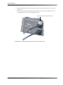
Red LED Indicates Failed Disk Drive ................................................................................. 44
Removing the DP600 Drive Cover ...................................................................................... 45
Remove the Drive Retaining Bracket .................................................................................. 45
Physical Drive Numbers ...................................................................................................... 46
Remove Failed Drive from DP600....................................................................................... 46
Insert Replacement Drive in DP600 .................................................................................... 47
Reinstall Retaining Bracket ................................................................................................. 47
Reinstall Front-Panel Drive Cover ....................................................................................... 48
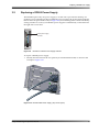
DP600 Front-Panel Power Supply Indicator........................................................................ 51
DP600 Failed Power Supply (Top Unit in Figure)................................................................ 51
Loosen Thumbscrew on Failed Power Supply .................................................................... 52
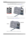
Press on Tab and Pull Handle to Remove Failed Power Supply ........................................ 52
Remove Failed Power Supply ............................................................................................. 53
Install New Power Supply.................................................................................................... 53
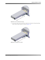
New Power Supply Installed and AC Cable Reconnected .................................................. 54
Calibration Setup Screen..................................................................................................... 55
Add Workorder Screen ........................................................................................................ 58
Enter Path Screen ............................................................................................................... 59
Type URL in Enter Path Screen .......................................................................................... 59
URL Entered in Add Workorder Screen .............................................................................. 60
Click Browse........................................................................................................................ 60
Select Protocol Screen ........................................................................................................ 60
Enter User Credentials Screen............................................................................................ 61
Enter Server Details Screen ................................................................................................ 61
Select File Screen ............................................................................................................... 62
Create Bookmark................................................................................................................. 63
Add Bookmark Screen......................................................................................................... 63
Selecting a Bookmark.......................................................................................................... 64
Bookmark Entered in Source Field...................................................................................... 64
Dolby® DP600 Program Optimizer Manual
Chapter 1
Introduction
Welcome to Dolby® file‐based audio!
The Dolby DP600 Program Optimizer is a direct result of Dolby Laboratories’ continued leadership in the development of innovative broadcast technologies. This innovative tool is designed specifically for cable, satellite, IPTV, and terrestrial TV broadcasters that employ a file‐based infrastructure and work flow. The DP600 includes the world’s first intelligent audio analysis and automated loudness normalization engine for many of the most common broadcast media file and audio formats in use today. In addition, it offers Dolby E, Dolby Digital, and Dolby Digital Plus encoding, decoding, and transcoding, all in an open architecture.
Using the DP600, broadcasters can provide their viewers with a consistent audio experience and reduce loudness complaints across all of their programs, channels, and networks. Expanding upon the unique Dialogue Intelligence™ technology developed for the Dolby LM100 Broadcast Loudness Meter, the DP600 normalizes the loudness of audio programs with no impact on their original dynamic range.
The DP600 automates previously lengthy quality‐control processes, and performs them in faster than real time. It automatically analyzes audio bitstreams coded in Dolby E, Dolby Digital, and Dolby Digital Plus, for any channel configuration and loudness level. It intelligently and automatically sets, validates, and corrects the dialogue normalization (dialnorm) audio metadata parameter without the need for decoding and reencoding—
ensuring a properly encoded bitstream. The DP600 also provides intelligent and automatic speech‐based loudness normalization for both PCM audio and MPEG‐1 LII audio.
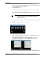
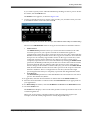
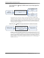
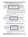
For compressed audio formats that include metadata (for example, Dolby E, Dolby Digital, and Dolby Digital Plus), the Dolby DP600 can automatically set or correct the dialnorm parameter (see Figure 1‐1). For audio formats that do not include metadata, the Dolby DP600 can automatically set or correct the dialnorm parameter by referencing a user‐defined target level (see Figure 1‐2). The Model DP600‐C adds faster‐than‐real‐time file‐based encoding and decoding of Dolby Digital and Dolby Digital Plus, and the first file‐based implementation of Dolby E. In addition, this model enables multichannel audio transcoding of Dolby E to Dolby Digital or Dolby Digital Plus formats. It also provides a unique high‐quality, single‐step Dolby Digital to Dolby Digital Plus transcoder that preserves the metadata and minimizes tandem coding losses. This allows the audio from existing media archives to be converted to next‐generation broadcast formats.
Dolby® DP600 Program Optimizer Manual
1
Introduction
Figure 1‐1
Dolby DP600 Program Optimizer
Uncorrected File
Broadcast Media File with
Dolby E, Dolby Digital, or
Dolby Digital Plus
Analyzed and
Corrected File
Broadcast Media File with
Dolby E, Dolby Digital, or
Dolby Digital Plus
Analyze Audio
Analyze Dolby Metadata
01101010011010100111001101110000
Yes
Error = 0?
Audio Stream
and Metadata Are
Already OK
No
Update/Correct
Metadata
Figure 1-1
Coded Audio with Metadata Analysis and Correction
Figure 1‐2
Dolby DP600 Program Optimizer
Uncorrected File
Broadcast Media or
Multichannel WAV File
Without Metadata
Analyzed and
Corrected File
Broadcast Media or
Multichannel WAV File
Without Metadata
Analyze Digital Audio
n channels
n channels
User-Defined Target Level
–(xx) dBFS
Yes
Error = 0?
Audio Loudness
Already at Target
Level (No Correction
Needed)
No
Scale Loudness
Level
Figure 1-2
2
Audio Analysis and Correction for Audio Types Without Metadata
Dolby® DP600 Program Optimizer Manual
Work Flow Integration
1.1
Work Flow Integration
You can integrate the DP600 into an existing file‐based network infrastructure where the unit functions as an intelligent processing node. In this environment, the DP600 adapts to your day‐to‐day operations and work flow, which includes:
1.2
•
Program ingest, audio transcoding, and quality control: Newly ingested content can be routed through the DP600 for loudness analysis and correction, encoding, decoding, and transcoding processes before being moved to your media storage library or play‐out server. •
Postproduction: File‐based Dolby E, Dolby Digital, and Dolby Digital Plus bitstreams can be encoded and decoded to and from multichannel .wav or Broadcast WAV Format (BWF) files with metadata (included in the Dolby audio metadata chunk). File‐based media and audio assets can be analyzed, logged, and (if necessary) corrected in faster than real time before delivery to clients. •
Ad insertion: Newly ingested ad content can be passed directly to the DP600 for loudness analysis and correction before it’s placed in your storage archive or ad server. •
Video‐on‐demand (VOD): Customer‐facing VOD servers, as installed at cable and IPTV head‐ends, need to have their content normalized before it is made available to the public. This content can be supplied to the servers either directly, via an ingest department at the broadcaster or affiliate, or via satellite from one or more content aggregators. The DP600 can be installed at the content aggregator, normalizing content before it is sent (ʺpitchedʺ) over the satellite link. Alternatively, it can be installed at the head‐end, taking content that has either been ingested directly or caught from one or more pitchers and normalizing it before it is passed to the customer‐facing server.
Work Flow Flexibility and Ease of Use
The Dolby DP600 platform suits several types of applications, including archiving, automated quality control, content conversion, and media asset management, and it offers considerable potential for integration with third‐party systems through an open application programming interface (API).
You can control the DP600 and its processing engines in three ways to suit specific user requirements. •
Manual control: Users can set up and initiate work orders on an individual or batch basis from a simple‐to‐use interface. •
Third‐party control via Web services: To enable system integration at any level, the DP600’s processing engines are also available as a set of Web services. This allows manufacturers to integrate these engines directly into their work flow to create a seamless user experience without impacting day‐to‐day operations. •
Automatic hot folder ingest process: Users can create hot folders and predefine a work order profile for each one. The profile governs the DP600’s behavior with specific broadcast media types. All media files moved to a hot folder are automatically processed based on the folder’s profile and delivered to a user‐defined folder upon completion. Hot folders are easy to set up and use and can greatly speed integration time within some facilities.
Dolby® DP600 Program Optimizer Manual
3
Introduction
1.3
Applications
The DP600 platform has many applications in terrestrial, satellite, cable, and IPTV broadcasting.
Cable and IPTV Applications
•
Automated VOD file analysis and loudness correction •
Automated VOD file transcoding: ‐ MPEG‐1 LII to Dolby Digital (AC‐3) ‐ Dolby Digital (AC‐3) to Dolby Digital Plus (E‐AC‐3)
•
Automated digital program insertion (DPI) file analysis and loudness correction •
Automated broadcast media file (GXF, others) audio transcoding: ‐ Dolby E to Dolby Digital ‐ Dolby E to Dolby Digital Plus ‐ Dolby Digital to Dolby Digital Plus •
Automated broadcast media file quality control and loudness correction Satellite Applications
•
Automated broadcast media file (GXF, others) audio transcoding: ‐ Dolby E to Dolby Digital ‐ Dolby E to Dolby Digital Plus ‐ Dolby Digital to Dolby Digital Plus •
Automated broadcast media file quality control and loudness correction •
Pay‐per‐view (PPV) file analysis and loudness correction •
Pay‐per‐view file audio transcoding Terrestrial Broadcast Applications
1.4
•
Automated broadcast media file quality control and loudness correction •
Automated broadcast media file transcoding
Supported Media Formats and Audio Types
The DP600 supports many media formats and audio types, including media file formats and linear and coded audio types.
Media File Formats
GXF (SMPTE 360M), MPEG‐2 program stream, MPEG‐2 transport stream
Linear Audio Types
.wav, BWF, and multichannel .wav files with or without a Dolby audio metadata chunk at
16‐, 20‐, and 24‐bit PCM (within any of the listed media file formats above)
Coded Audio Types
Dolby E, Dolby Digital (AC‐3), Dolby Digital Plus (E‐AC‐3), MPEG‐1 LII
4
Dolby® DP600 Program Optimizer Manual
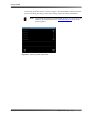
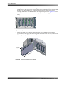
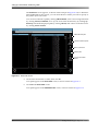
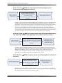
DP600 Front Panel
1.5
DP600 Front Panel
The DP600 front panel includes the following components:
Figure 1‐3
•
Touch screen user interface
•
CD/DVD drive and system reset and display controls (behind touch screen door)
•
Power supply indicators •
Local storage indicators
•
USB 2.0 port
Touch screen user interface
Power supply indicators
DP600 Program Optimizer
!
!
1
2
3
4
USB 2.0 port
Figure 1-3
DP600 Front Panel
1.5.1
Touch Screen User Interface
Local storage indicators
The LCD touch screen provides user controls for rescheduling, cancelling, and pausing work orders and reports and checking the system status. You simply touch the icon that represents the desired function, and the DP600 responds accordingly. To add and configure work orders and export reports, you need to use the DP600 Client. For a complete description of all work order functions, see Understanding Work Orders on page 27. 1.5.2
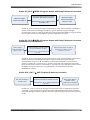
CD/DVD Drive
The CD/DVD drive is located behind the touch screen door. With this drive, you can perform DP600 software upgrades.
Figure 1‐4
System Reset and Display buttons
CD/DVD drive
Figure 1-4
Note:
DP600 CD/DVD Drive (Behind Touch Screen Door)
You cannot play commercial CDs or DVDs in the DP600 CD/DVD drive.
Dolby® DP600 Program Optimizer Manual
5
Introduction
1.5.3
System Reset and Display Controls
These recessed buttons are located behind the touch screen, above the CD/DVD drive. If you need to press any of these buttons, use a nonconductive material, such as a toothpick. If you press the System Reset button, the system restarts. Press this recessed button only if you cannot restart the system using the DP600 software (or by pressing <Ctrl>+<Alt>+ <Delete> to restart, as described on page 26. Always avoid restarting by disconnecting and reconnecting the power cables.
You can use the Display control button to adjust the LCD display.
1.5.4
Power Supply Indicators
Three power supply LEDs on the front panel indicate whether the power is on, if one of the redundant power supplies has failed, and the temperature of the unit. Power: This green LED lights when the DP600 has power. !
Power supply failure: This red LED is off during normal operation. It lights or flashes red if either of the redundant power supplies fails.
Temperature: This tricolor LED glows green when the temperature of the unit is cool, yellow if the temperature is warm, and red if the temperature is hot. If this LED is yellow or red, the operating environment may be warmer than expected and in need of modification. In such a case, call your Dolby authorized technical representative immediately.
1.5.5
Internal Drive Indicators
1
2
3
4
The DP600 has five physical internal hard drives. Drives 1 and 2 are arranged in a RAID 1 configuration to provide protection for the operating system as well as local storage. The remaining three hard drives are configured as separate drives to provide local storage. This configuration of one RAID pair and three separate drives represents four logical drives. There are four bicolor LEDs on the front panel, labeled 1, 2, 3, and 4. These LEDs indicate the status of the DP600’s four logical internal hard drives. The drive LEDs function as follows:
Off (non‐illuminated): Indicates a functional drive with no current disk access activity.
Green: Indicates normal drive activity.
Red: Indicates a drive failure.
LED 1 shows the status of the two‐drive RAID 1 configuration. The operating system is installed on these mirrored drives to prevent a physical drive failure, resulting in an inoperable system. If either of the mirrored drives fails, the other RAID drive enables the system to operate normally until the failed drive is replaced.
6
Dolby® DP600 Program Optimizer Manual
DP600 Front Panel
LEDs 2, 3, and 4 indicate the status of the other three physical disks. These disks are configured as separate drives and do not have RAID backup capability. If any of these drives fail, the failed drives must be replaced, and any work orders in progress during the failure must be restarted. If one of the drive LEDs turns red, refer to Table 1‐1 to determine which physical drive failed. Typically, the DP600 automatically rebuilds the RAID array when one of the RAID drives has a problem or is replaced (with the power on). During the RAID rebuild process, LED 1 blinks in red in half‐second intervals. When the rebuild process is complete, LED 1 stops blinking. In some instances, you must initiate the rebuild process manually (as described in Rebuilding a Drive on page 49). For example, if you replace a non‐RAID drive. If you replace both RAID drives, you also need to reinstall the DP600 software. In such a case, follow the instructions for a clean installation in Upgrading/Installing the DP600 Software on page 55. When you reinstall the software, the system automatically synchronizes the two RAID drives, recreating the original mirrored RAID array (manual rebuild not required).
For instructions on replacing a drive, see Replacing a Drive on page 44.
Table 1-1
Local Storage LED Conditions
Front-Panel LED
1
1
1
2
3
4
1.5.6
Condition
Solid red
Blinks in red in two‐second intervals
Blinks in red in half‐second intervals
Solid red
Solid red
Solid red
Failed Physical Drive
1
2
Rebuilding RAID
3
4
5
USB 2.0 Port
The front panel USB 2.0 port is provided for license loading from a USB flash drive or to connect the provided USB keyboard.
Dolby® DP600 Program Optimizer Manual
7
Introduction
1.6
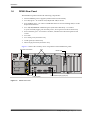
DP600 Rear Panel
The DP600 rear panel includes the following components:
•
Dual‐redundant power supplies (with red alarm reset button)
•
Two PS/2 ports—To connect a PS/2 keyboard and/or mouse
•
Four USB 2.0 ports—To connect a USB flash drive for license loading and/or a USB keyboard and mouse
•
Two 10/100/1000BASE‐T Ethernet ports (with auto‐detection)—To connect to your network (upper port currently active, lower port reserved for future use)
•
SVGA monitor port—To connect a monitor, which mirrors the front‐panel touch screen
•
Two fans
•
Two serial ports (for future use)
•
Audio ports (for future use)
•
Three empty PCI slots (for future use)
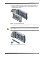
Figure 1‐5 shows the currently active components on the DP600 rear panel.
Figure 1‐5
Fans
Red alarm reset button
Monitor port
WARNING
Model DP600
Program Optimizer
Risk of electric shock.
Do not open.
No user serviceable parts
inside. Refer all service
to qualified personnel.
MAINS INPUT
100–240Vac
3.0–1.25A 50/60Hz
This equipment must be
earthed/grounded.
Power Supply
Alarm Reset
Dolby and the double-D symbol are registered trademarks of Dolby Laboratories.
Power supplies
PS/2 ports
USB 2.0 ports
Figure 1‐6
Figure 1-5
8
Active Ethernet port (upper port)
DP600 Rear Panel
Dolby® DP600 Program Optimizer Manual
Chapter 2
Using the DP600
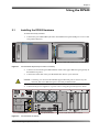
2.1
Installing the DP600 Hardware
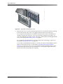
To install the Dolby® DP600:
1.
Connect the provided USB keyboard to the DP600 front‐panel USB port or one of the rear‐panel USB ports.
Figure 2‐1
DP600 Program Optimizer
!
!
1
2
3
4
Connect provided USB keyboard here or in rear panel
Figure 2-1
Connect DP600 Keyboard (Front-Panel connection)
2.
Connect one end of the provided Ethernet cable to the upper Ethernet port (port 0) on the DP600 rear panel.
3.
Connect the other end of the provided Ethernet cable to your network.
Caution: Currently, you must use the DP600’s upper Ethernet port to connect to your network. The lower Ethernet port is currently nonfunctional.
4.
Connect both power supplies to a power source using the provided power cables.
Figure 2‐2
WARNING
Model DP600
Program Optimizer
Risk of electric shock.
Do not open.
No user serviceable parts
inside. Refer all service
to qualified personnel.
MAINS INPUT
This equipment must be
earthed/grounded.
100–240Vac
3.0–1.25A 50/60Hz
Power Supply
Alarm Reset
Dolby and the double-D symbol are registered trademarks of Dolby Laboratories.
Connect power
Figure 2-2
Rear-panel USB ports
Connect upper Ethernet port to network
Connect DP600 to Network
Dolby® DP600 Program Optimizer Manual
9
Using the DP600
2.2
Starting the System for the First Time
Caution: Before starting the system, be sure it’s connected to an active network.
The DP600 touch screen provides a user‐friendly interface where you perform actions by pressing the respective screen area. The touch screen is calibrated during the manufacturing process.
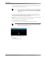
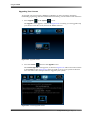
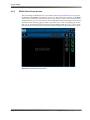
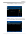
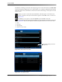
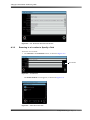
When you start the DP600 for the first time, the DP600 Welcome! screen appears, which provides a checklist of things you need before you can set up the system, as shown in Figure 2‐3.
Figure 2‐3
Figure 2-3
DP600 Welcome! Screen
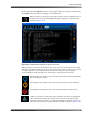
To configure the system:
1.
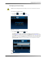
Be sure you are ready to proceed by checking the Welcome! screen, then press the right arrow at the bottom of the screen.
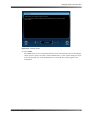
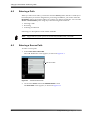
The Network screen appears, as shown in the example in Figure 2‐4. Before you set up the system, the IP address appears only if you enter a static IP address (DHCP unchecked). If you’re using DHCP, the IP address does not appear until you complete the system setup.
Note:
10
In this screen, and in all the following DP600 setup screens, you enter information to configure your system. If you press the cancel button at the bottom left corner of any of the following setup screens, the system cancels all of your entries (in all the setup screens, in addition to the currently displayed setup screen). A cancel confirm prompt appears. If you confirm, the unit cancels your entries and automatically reboots, and then the Welcome! screen reappears. At this point, you can reenter your settings.
Dolby® DP600 Program Optimizer Manual
Starting the System for the First Time
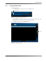
Figure 2‐4
Figure 2-4
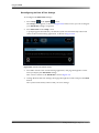
2.
Network Screen
Be sure the provided USB keyboard is connected to one of the DP600 USB ports.
You can connect the keyboard to any free USB port (front or rear panel), but we recommend using one of the rear‐panel USB ports, because the front panel is more convenient for inserting a USB flash drive (which is required to load a license).
3.
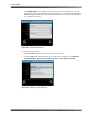
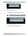
In the General Configuration box, press the Hostname field, then use the keyboard to enter a host name. Currently, you must use the keyboard to make entries in the Hostname field. Enter a unique name with no spaces or other nonconventional network naming characters (for example, dp600‐unit‐1).
4.
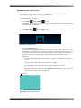
In the General Configuration box, press on the Gateway field.
The Enter Gateway Address number pad appears, as shown in Figure 2‐5.
Figure 2‐5
Figure 2-5
Enter Gateway Address Number Pad Screen
Dolby® DP600 Program Optimizer Manual
11
Using the DP600
5.
Press on the desired numbers to enter an optional gateway address, then select ok.
6.
In the Upper Interface Settings box, press the Use DHCP box (if it is unchecked) for dynamic addressing or uncheck this box (by pressing on it) if you want to enter a fixed IP address. The upper interface corresponds to the top Ethernet port (port 0) on the DP600 rear panel. The lower interface (bottom port) is currently nonfunctional.
7.
If you specified a fixed IP address, the respective fields are now active. Make your entries by pressing on the IP Address and Netmask fields to display the corresponding number pad screens, then press on the appropriate numbers (see gateway address number pad instructions above). Alternatively, you can press on the field, and then use the USB keyboard to make your entries (as described earlier for the Hostname field).
8.
Press the right arrow at bottom of the Network screen.
The Date & Time screen appears, as shown in Figure 2‐6.
Figure 2‐6
Figure 2-6
9.
Date & Time Screen
Press the Server Date & Time field.
The Set Server Date/Time screen appears, as shown in Figure 2‐7.
Figure 2‐7
Set Figure 2-7
12
Set Server Date/Time Screen
Dolby® DP600 Program Optimizer Manual
Starting the System for the First Time
10. Press the up and down arrows above and below each field to set the server date and time, then press ok.
11. Press the Server Time Zone field.
The Select Region screen appears, as shown in Figure 2‐8.
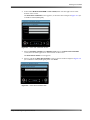
Figure 2‐8
S
Figure 2-8
Select Region Screen
12. Press on your region, then press the right arrow.
The Select City or Zone screen appears for your region, as shown in Figure 2‐9.
You need to select your closest city to ensure that submitted work orders run at the scheduled time.
Figure 2‐9
L
Figure 2-9
Select City or Zone Screen
Dolby® DP600 Program Optimizer Manual
13
Using the DP600
13. Press on your closest city, then press finish.
The End User License Agreement screen appears, as shown in Figure 2‐10.
Figure 2‐10
Figure 2-10 License Agreement Screen
14. Read the license agreement and be sure you understand it, then press the I understand
and accept these terms box, then press the right arrow.
The License screen appears. This screen displays the unit’s Serial Number and user personal identification number (PIN). Note these two numbers—you’ll need them to license your unit for operation. You’ll also need access to a computer with an Internet connection and an available USB port. Figure 2‐11
Figure 2-11 License Screen
14
Dolby® DP600 Program Optimizer Manual
Starting the System for the First Time
15. Obtain the USB flash memory stick from the DP600 packing kit, and insert it into a PC connected to the Internet. 16. Open a Web Browser and go to www.dolbysupport.com.
17. If you are already registered, simply log in.
18. If you are a new user, please take a few moments to register.
19. Once logged in, click Product Licensing on the DolbySupport home page, as shown in Figure 2‐12.
A shortcut to DP600 product licenses may also appear under Product Licensing. If this shortcut appears, you can click on it to go directly to the Get License File page.
Figure 2‐12
Click Product
Licensing
or DP600 Get
License Shortcut
Figure 2-12 Select Product Licensing on DolbySupport Home Page
The Get New License File page appears, as shown in Figure 2‐13.
Figure 2‐13
Enter required information, then click Register product Figure 2-13 Get New License File Page
Dolby® DP600 Program Optimizer Manual
15
Using the DP600
20. Select DP600 from the Product drop‐down menu if it is not already selected.
21. Enter the required information in the rest of the fields (the unit’s Serial Number is displayed on the DP600 touch screen, as shown in the example in Figure 2‐11).
22. Fields marked with an asterisk (*) are required.After entering information in all the required fields, select Register product near the bottom of the page, as shown in Figure 2‐13.
Once the product is registered, a message in red text near the top of the screen informs you that the DP600 is now registered, and the registered product information appears at the bottom of the screen (identified by serial number) and as shown in Figure 2‐14.
Figure 2‐14
Enter PIN
Click Download
to download license
Click Upgrade
to upgrade license
Figure 2-14 Product Registered Page
23. To download a license and/or upgrade the unit:
16
•
To download a license, type the unit’s PIN in the field next to the serial number (the PIN is displayed on the DP600 touch screen, as shown in the example in Figure 2‐11), then click Download. Proceed to step 24.
•
To upgrade the unit, click Upgrade. The Upgrade Serial Number page appears, as shown in Figure 2‐14. Enter the unit’s PIN and upgrade key and click Upgrade
again.
Dolby® DP600 Program Optimizer Manual
Starting the System for the First Time
Figure 2‐15
Enter PIN
Enter upgrade key
Click Upgrade
Figure 2-15 Upgrade Serial Number
All upgrades appear at the bottom of the screen under Previous Upgrades. When you are done, click the Done button. On the Get License page, enter the unit’s PIN next to its serial number and click Download to download your new license (with all upgrades applied). Proceed to step 24. Figure 2‐16
Upgrade displayed
Figure 2-16 Upgrade Appears Under Previous Upgrades
Dolby® DP600 Program Optimizer Manual
17
Using the DP600
You can repeat the previous steps for each license you want to download and each upgrade you want to apply to your license.
Note:
After you apply your system upgrade keys, future downloads do not require reentering the keys. After entering your PIN, click Download, and your license automatically downloads (including all applicable upgrade keys).
24. At the prompt, save the downloaded file to the USB flash memory stick that you previously inserted into the PC you are using to view this Web page. This file is the license for your DP600 system (including any upgrades).
25. Remove the flash memory stick from the PC, then insert it into one of the DP600 USB ports. It will take a few seconds for the DP600 to recognizes the license.
26. Press the license button in the License screen.
A confirmation prompt informs you that the license installed successfully. Note:
Figure 2‐17
If the system does not install the license, press the license button again. The system may take a few seconds to recognize the inserted flash drive containing the license file.
Figure 2-17 License Confirmation Prompt
27. Press ok.
The Finished! screen appears.
18
Dolby® DP600 Program Optimizer Manual
Starting the System for the First Time
Figure 2‐18
Figure 2-18 Finished! Screen
28. Press finish.
The DP600 setup is now completed and the system automatically reboots. During the reboot process, remove any discs in the CD/DVD drive, as the system attempts to boot from any inserted disc. If an installation disc is inserted, the system begins a new installation.
Dolby® DP600 Program Optimizer Manual
19
Using the DP600
2.2.1
DP600 Home Screen
After you complete the DP600 setup, the unit automatically reboots and the DP600 home screen appears, as shown in Figure 2‐19. This screen displays the date and time at the upper right corner. The system status in the right column shows icons indicating the current status of the server, network (net), and disk(s). A green “happy face” indicates all is OK. A red “unhappy” face indicates a problem. If you see an “unhappy face,” touch the corresponding icon to display additional information.
The work orders and reports icons also appear in the home screen. You’ll learn how to use the work order and report functions later in this chapter, as described in Understanding Work Orders on page 27. Figure 2‐19
Figure 2-19 DP600 Front-Panel Home Screen
20
Dolby® DP600 Program Optimizer Manual
Starting the System for the First Time
2.2.2
Using the System Screen
The system screen allows you to check the system status, reconfigure the network and date and time, upgrade your license, and reboot and shut down the system.
Checking the System Status
To check the system status:
1.
Press system
at the upper right side of the home screen.
The system screen appears, as shown in Figure 2‐20. Grayed‐out icons are currently nonfunctional.
Figure 2‐20
Figure 2-20 System Screen
2.
Press status
in the system screen.
The Software Information screen appears, as shown in Figure 2‐21.
Figure 2‐21
Figure 2-21 Software Information Screen
Dolby® DP600 Program Optimizer Manual
21
Using the DP600
Upgrading Your License
To upgrade your license from a DP600 to a DP600‐C (to allow encoding, decoding, transcoding, upmixing, and other additional functionality), use the touch screen as follows:
1.
Press upgrade in the system screen.
The upgrade screen appears, as shown in Figure 2‐22. Currently, you can upgrade only your license from this screen, but not the DP600 software. Figure 2‐22
Figure 2-22 Upgrade Screen
2.
Press the license button in the upgrade screen.
The License Upgrade screen appears, as shown in Figure 2‐23. This screen looks similar to the License screen in Figure 2‐11 that you used to set up your system for the first time. You follow the same procedure to upgrade your system.
Figure 2‐23
Figure 2-23 License Upgrade Screen
22
Dolby® DP600 Program Optimizer Manual
Starting the System for the First Time
Reconfiguring the Network Settings
Caution: Before changing the network settings, be sure you’re connected to a network.
To reconfigure the network settings:
1.
Press config
in the system screen.
The config screen appears, as shown in Figure 2‐24. Figure 2‐24
Figure 2-24 Config Screen
2.
Press network in the config screen.
The network screen appears, where you can reconfigure your network settings, as shown in Figure 2‐25. This screen is similar to the network screen in Figure 2‐4, except for the undo button at the lower left corner. The undo button in this screen replaces the cancel button. If you press the undo button, the system deletes your new entries in this screen only. After changing your network settings, you are prompted to manually reboot the system. Figure 2‐25
undo
button
Figure 2-25 Network Screen
Dolby® DP600 Program Optimizer Manual
23
Using the DP600
Reconfiguring the Date & Time Settings
To reconfigure the date & time settings:
1.
in the system Press config
screen.
The config screen appears, as shown in Figure 2‐24. In this screen, you can reconfigure your date & time settings, if required. 2.
Press date & time in the config screen. A prompt appears that informs you that the system will automatically reboot and return to the commissioning application, as shown in Figure 2‐26.
Figure 2‐26
Figure 2-26 Date & Time Reboot Screen
3.
Press ok to return to the commissioning application, and page through the screens until you display the date & time settings.
This screen is similar to the date & time screen in Figure 2‐6. 4.
Change the date and time settings, then page through the screens and press the finish button.
The system automatically reboots with your new settings.
24
Dolby® DP600 Program Optimizer Manual
Starting the System for the First Time
Recalibrating the Touch screen
Your DP600 touch screen was calibrated during the manufacturing process, but occasionally, you may need to perform a recalibration. To recalibrate the touch screen:
1.
in the system Press config
screen.
The config screen appears, as shown in Figure 2‐24. In this screen, you can recalibrate the touch screen, if required. 2.
Press touchscreen
in the config screen. The calibrate button appears, as shown in Figure 2‐27.
Figure 2‐27
Figure 2-27 Calibrate Button
3.
Press the calibrate button.
The calibration setup appears with a small target at the upper left corner, and a cross at each of the other three corners, as shown in Figure 2‐28. To calibrate the touch screen, you need to proceed as follows within approximately 30 seconds from the time it appears. If you do not proceed within this time period, the calibration screen disappears.
•
Press the target at the upper left corner for a couple of seconds until it changes to a cross. The cross at the upper right corner changes to a target. •
Press the target at the upper right corner until it changes to a cross.
•
Continue the above procedure at the lower left corner and the lower right corner.
When the calibration is complete, the calibrate button reappears, and you can now move on to any other screen, as required.
Figure 2‐28
Press target
Figure 2-28 Calibration Setup Screen
Dolby® DP600 Program Optimizer Manual
25
Using the DP600
Rebooting and Shutting Down the System
To reboot or shut down the system:
1.
Press power in the system screen.
The power screen appears, as shown in Figure 2‐29.
Figure 2‐29
Figure 2-29 Power Screen
2.
To reboot or shut down the system, press reboot or shutdown, respectively.
A confirmation prompt asks if you’re sure you want to reboot (or shutdown) the DP600, as shown in the example in Figure 2‐30 for a reboot.
Figure 2‐30
Figure 2-30 Reboot DP600 Confirmation Prompt
26
Dolby® DP600 Program Optimizer Manual
Using the DP600 Remote Client Software
3.
Press ok at the prompt to reboot (or shut down) the system.
If pressing the reboot button does not work, you can press <Cntrl>+<Alt>+<Delete> on the provided keyboard. When you shutdown, the Dolby DP600 Program Optimizer screen appears. When you see this screen, disconnect the power cable to shut down completely.
Caution: Currently the front panel touch screen may not display the local home screen following a system restart, while remote clients continue to display correctly. In such a case, reboot the system again to display the local home screen.
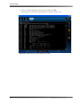
2.3
Using the DP600 Remote Client Software
To process audio using the DP600, you need to use the Dolby DP600 Remote Client software (also referred to as “DP600 Client“ or “Client”). With this application, you can define and run an operation we call a work order. The DP600 Client runs on your Microsoft® Windows® PC. This application looks similar to the front panel touch screen, but provides more user control functions. For example, with the Client, you can:
2.3.1
•
Add and configure work orders
•
Run work order profiles to analyze dialogue levels, perform dialogue normalization, and encode/transcode/decode audio files
•
Export work order reports
Understanding Work Orders
Currently, there are five types of work orders:
•
•
Standard
Pinnacle Standard
•
Hot Folder •
•
Pinnacle Hot Folder
Grass Valley Hot Folder
Standard and Pinnacle Standard Work Orders
These type of work orders process audio on a file‐by‐file basis. You specify the path to the source file on your PC or anywhere on the network. You also specify a destination where you want to save the processed file. Pinnacle work orders are designed specifically for Pinnacle Systems® MediaStream™ server files.
Hot Folder Work Order
With this type of work order, you specify the path to a source folder on your PC or network where the audio files you want to process are located. The DP600 periodically looks for files of a specific type in this folder, which is controlled by the work order profile. The work order profile associated with your hot folder also determines how the DP600 processes the files. In addition, you specify the destination where you want to save the processed files. Dolby® DP600 Program Optimizer Manual
27
Using the DP600
When the DP600 sees the specified file type in the source directory, it processes those files according to the current profile, and then saves the processed files in the destination folder. Note:
You can link only one work order profile with a single hot folder. However, you can create multiple hot folders, each with a different profile.
Pinnacle Hot Folder Work Order
This type of hot folder is designed specifically for Pinnacle MediaStream server files.
Grass Valley Hot Folder Work Order
This type of hot folder is designed specifically for Grass Valley™ Profile® and Profile XP server files.
Work Order Profile
While the type of work order indicates how the DP600 accesses audio files, the work order profile controls the processing specifications (for example, whether the DP600 performs audio loudness analysis and correction, transcoding/encoding/decoding, or other actions on the respective audio files).
28
Dolby® DP600 Program Optimizer Manual
Using the DP600 Remote Client Software
2.3.2
Running the DP600 Client
To run the Client:
1.
Open your browser and go to http://<dp600 server>/,where <dp600 server> is the host name or IP address of the DP600 (for example, http://zico.eng/ or http://10.201.1.88/). After you open the Client for the first time, a shortcut appears on your desktop and in the Start>All Programs>Dolby Laboratories menu.
Currently we support Windows XP, using Internet Explorer® versions 6 and 7, Firefox® 2, and Opera 9. Other browsers and operating systems are untested or unsupported.
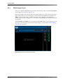
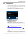
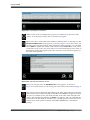
The DP600 Program Optimizer splash screen appears, as shown in Figure 2‐31.
Figure 2‐31
T
Download manual
Download Java
Click launch client
Figure 2-31 DP600 Program Optimizer Splash Screen
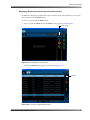
2.
Click launch client in the splash screen.
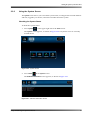
Sun Microsystem’s Java® Web Start launches, the Client automatically connects to the DP600, and the DP600 Client home screen appears, as shown in Figure 2‐32. Subsequently, you can start the Client with either the shortcut described above, or by revisiting the DP600 Web page and following the links again.
If the Client PC does not have the correct version of the Java Runtime Environment (JRE) installed and the Client PC has access to the Internet, the correct version of Java installs automatically. If this fails, then you need to install the JRE manually by clicking the icon on the splash screen or going to www.java.com/en/download/manual.jsp?locale=en&host=www.java.com. You can download a copy of the DP600 manual (this manual) by clicking the icon.
If the current version of Client software is not already installed on the Client PC, the correct version automatically downloads directly from the DP600 (no Internet access required).
You can install and run the Client from multiple computers simultaneously. Client updates automatically occur each time the Client runs on a specific PC. For this reason, the Client isnʹt really installed as such. You simply run the application from the DP600, which automatically downloads any necessary files and updates as required.
Dolby® DP600 Program Optimizer Manual
29
Using the DP600
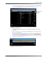
2.3.3
DP600 Client Home Screen
After launching the DP600 Client, as described in Running the DP600 Client on page 29, the DP600 Client home screen appears on your PC. This screen looks similar to the home screen on the front‐panel touch screen and you can perform many of the same functions using the Client. You can also perform some additional functions. The Client functions are described on the following pages. When a procedure says “click” something, this means that you can perform the respective function only with the Client. If it says “press or click,” this means you can perform the respective function using the touch screen or the Client.
Figure 2‐32
Figure 2-32 DP600 Client Home Screen
30
Dolby® DP600 Program Optimizer Manual
Creating a Work Order
2.4
Creating a Work Order
To create a work order: 1.
Figure 2‐33
Click work orders near the upper left corner of the home screen.
{Click work orders
Figure 2-33 Displaying the Work Order Screen
The work orders screen appears, as shown in Figure 2‐34. In this screen, you can add and configure a work order and perform other related functions.
2.
Figure 2‐34
Click add at the right side of the work orders screen.
Click add
Figure 2-34 Adding a Work Order
Dolby® DP600 Program Optimizer Manual
31
Using the DP600
The Add Workorder screen appears, as shown in Figure 2‐35. In this menu, you can enter information in the displayed fields to configure your work orders. In addition, a Notes field appears below the work order fields, where you can enter some related text for a specific work order.
Figure 2‐35
Figure 2-35 Add Workorder Screen
To set up your work order:
Figure 2‐36
1.
Click the Name field, then enter a name for your work order.
2.
Click the Type field, then select the type of work order you’d like to run (Standard, Pinnacle Standard, Hot Folder, Pinnacle Hot Folder, or Grass Valley Hot Folder).
Figure 2-36 Selecting a Work Order Type
32
Dolby® DP600 Program Optimizer Manual
Creating a Work Order
3.
Click the Source field.
The Enter Path screen appears, as shown in Figure 2‐37. In this screen, you can enter the path to the file or folder (for a hot folder) that you want to designate for processing. Before entering a path, be sure you’re connected to an active network, and then set up a shared folder for all authorized users, as described in Setting Up a Shared Folder on page 57.
Note:
Supported file system protocols include FTP, SAMBA/CIFS, and SFTP.
You can enter a path using any of the following methods: •
Enter a URL (directly)
Type the desired URL in the URL field. You must pre‐encode your URL entry, which cannot include the username/password/domain information in the URL field. For example, smb://dp600/users/common/hot_folder/. If necessary, you can enter a Username, Password, and Domain (SMB only) in the corresponding fields below. After entering the URL, click ok.
•
Browse to the desired location
Click browse to display the Select Protocol screen (if the URL field is blank) and select either Windows Share/SMB or FTP or SFTP, then click the right arrow and (if necessary) enter a Username, Password, and Domain (SMB only) in the Enter User
Credentials screen. Click the right arrow and enter a path in the Enter Server
Details screen. Then click finish to display the Select File screen, click on the desired file or folder, then click ok. If you want to create a bookmark, click on the desired file or folder in the Select File screen, click add, then click ok. If you click browse and the URL field is not blank, the system attempts to browse to the entered URL.
•
Select a bookmark
Click on the Bookmarks field to display all the bookmarks you previously added in the Select File screen (as described previously), then select the desired bookmark to specify the path, and click ok. When you select a bookmark, it automatically appears in the URL field. If necessary, you must still enter a Username, Password, and Domain (SMB only), in the corresponding fields each time you select the bookmark. After selecting the bookmark, you can click browse to go to the corresponding location.
Note:
Figure 2‐37
For complete details on entering a path using the above three methods, see Entering a Path on page 58.
Figure 2-37 Enter Path Screen
Dolby® DP600 Program Optimizer Manual
33
Using the DP600
4.
Use one of the methods to enter the path to the file or folder (for a hot folder) that you want to designate for processing, then click ok.
Click the Destination field. The Enter Path screen appears. In this screen you can enter the path to the file or folder where you want to save the processed files. This screen is identical to the Enter Path
screen described earlier for the source path.
5.
Use one of the methods to enter the path to the location where you want to save the processed files, then click ok.
Note:
6.
You need to set up a shared folder for all authorized users and enter the correct syntax for your source and destination directories, as explained in Appendix A. If you want to start your work order immediately, use the default (Immediately) in the Start At field. If you want to specify a start time for your work order, click on the Start
At field.
The Start At screen appears, as shown in Figure 2‐38.
Figure 2‐38
Figure 2-38 Entering the Work Order Start Time
Figure 2‐39
7.
Use the up and down arrows to specify a day, month, year, and time when you want to start (run) the work order, then click ok.
8.
For Hot Folder, Pinnacle Hot Folder, and Grass Valley Hot Folder work orders (see Figure 2‐39), if you want to run your work order indefinitely, use the default (Indefinitely) in the End At field.
Figure 2-39 Hot Folder and Grass Valley Hot Folder Options (Pinnacle Hot Folder Options are the
same as Hot Folder Options, Grass Valley Hot Folder Shows Additional Options)
34
Dolby® DP600 Program Optimizer Manual
Creating a Work Order
If you want to specify a time when the DP600 stops looking for files to process in this hot folder, click the End At field.
The End At screen appears, as shown in Figure 2‐40.
9.
Use the up and down arrows to specify a day, month, year, and time when you want to end the hot folder work order, then click ok.
Figure 2‐40
Figure 2-40 Entering the Work Order End Time (For Hot Folders & Grass Valley Hot Folders Only)
The next two Add Workorder fields for all types of hot folders are defined as follows:
•
Stable Period
The Stable Period parameter allows you to fine‐tune the hot folder/work order activation process for your specific network environment.This applies to configurations where the system copies files from one server into a hot folder the DP600 is monitoring on another server. This is typical in work flow environments that process an extremely large number of files. In this type of work flow, some remote file systems cannot confirm to any degree of accuracy when a file is completely copied from its source into a hot folder. By utilizing the Stable Period parameter, the DP600 periodically checks the size of all new files in the hot folder, and waits until the file size stabilizes (does not increase in size). If the file size doesnʹt change for the number of milliseconds (ms) you enter in the Stable Period field, then the DP600 activates the work order process on the respective files.The default is 20,000 ms. This is a safeguard to be sure the system doesn’t begin processing files before they’re completely copied into the designated hot folder.
•
Scan Interval
The Scan Interval specifies how often the DP600 scans a hot folder for new files to process. The default is 5,000 ms.
10. If applicable, enter the desired number of milliseconds in the Stable Period field.
11. Enter the desired number of milliseconds in the Scan Interval field, if appropriate for your application.
12. For Grass Valley hot folders, enter the IP Address and IP Port of the Destination folder.
13. Click the Profile field.
The Profile menu displays a list of work order profiles. Use the up and down arrows to scroll through the list. When you click a profile, a short description of the selected profile appears (for example, transcode a Dolby Digital file to a Dolby Digital Plus file). Dolby® DP600 Program Optimizer Manual
35
Using the DP600
Profiles that perform loudness correction require a standard DP600, while profiles that perform encoding, decoding, and/or transcoding require the enhanced DP600‐C. Note:
Figure 2‐41
For detailed descriptions of all the DP600 profiles, see Appendix B. In addition, check the DP600 area of www.dolbysupport.com for periodic profile updates. Figure 2-41 Selecting a Work Order Profile
36
Dolby® DP600 Program Optimizer Manual
Creating a Work Order
14. Select the work order profile you want to use to process your files, then click ok.
After you add a work order, it runs as specified in the Add Workorder menu. When a work order is running, the home screen displays the progress, as shown in Figure 2‐42.
Figure 2‐42
Figure 2-42 Work Order Running as Displayed in Home Screen
After you add a work order, it appears in the work order screen database (when you select work orders in the home screen). The work order database displays the names, profiles, creation dates, status, scheduled start times, and source files for all work orders, as shown in Figure 2‐43. For hot folder work orders, a folder icon appears on the left side of each entry.
Figure 2‐43
Figure 2-43 Work Order Database
Dolby® DP600 Program Optimizer Manual
37
Using the DP600
In addition to adding work orders and displaying work order information, the work order screen also displays additional icons, which enable you to display additional information and pause, edit, cancel, and delete a selected work order. Following is a description of each of these icons:
When you select a work order in the database, and then press or click this icon, profile, schedule, and reports information appears in the info screen, as shown in Figure 2‐44.
In addition, if you press or click the reports icon in the info screen, the corresponding report information appears for the selected work order, as shown in Figure 2‐45. This screen displays the following information for each work order:
Figure 2‐44
•
Date •
Severity •
Description •
Name of work order
Click reports to display info shown
in Figure 2-45
.
Figure 2-44 Work Orders Info Screen
Figure 2‐45
Figure 2-45 Info Reports Screen
38
Dolby® DP600 Program Optimizer Manual
Creating a Work Order
On the right side of the reports screen, five icons appear. When you click any of these icons, the reports screen responds accordingly, as described below. When you press or click on a work order report to select it, and then press or click this icon, the corresponding detailed report appears, as shown in the example in Figure 2‐46.
Figure 2‐46
Figure 2-46 Detailed Report Displayed in Reports Info Screen
When you press or click any of the lower four icons, only work order reports associated with that icon appear. When you press or click again on the same icon, this type of report no longer appears. If you click more than one icon, the respective reports appear, corresponding to all the selected icons. Following is a description of each icon:
Selecting this icon displays any work order reports that contain information, but no warnings or errors.
Selecting this icon displays any work order reports that contain warnings.
Selecting this icon displays any work order reports that contain errors.
When you click on a work order report, and then click this icon (displayed only in the DP600 Client), the system saves a text file of the report to the desired location on your PC. A confirmation dialog box appears where you enter the desired name and path, and then click ok, as shown in Figure 2‐47.
Dolby® DP600 Program Optimizer Manual
39
Using the DP600
Figure 2‐47
Figure 2-47 Export Report Confirmation
When a work order is running and you press or click this icon, the work order pauses. To resume processing, click or press this icon again.
When you select a work order in the database, and then press or click this icon, the Edit Selected Workorder screen appears, as shown in Figure 2‐48. In this screen, you can edit your work order settings. After making the desired changes, you can either select update to update the current work order or select create new to create a new work order. If you create a new work order, we recommend entering a new name to differentiate it from the original work order. The new work order now appears in the work order database.
Figure 2‐48
Figure 2-48 Edit Selected Workorder Screen
When you click this icon, the Add Workorder screen appears, as shown in Figure 2‐35. In this menu, you can set up your work orders, as described on page 31.
One of these icons is displayed, depending on the state of the selected work order. If the selected work order is running or scheduled, the cancel icon appears and you can press or click this icon to cancel the selected work order. If the selected work order is not scheduled or running, the delete icon appears, and you can delete the work order from the database. In either case, a prompt appears, which asks you to confirm your action (cancel or delete). Select ok or cancel at the confirmation prompt.
40
Dolby® DP600 Program Optimizer Manual
Creating a Work Order
Displaying Work Order Reports from the Home Screen
In addition to displaying work order reports from the work order database, you can also access reports from the home screen. To access a report from the home screen:
1.
Figure 2‐49
Press or click the reports icon in the home screen, as shown in Figure 2-49.
Click reports
Figure 2-49 Click Reports in Home Screen
The home reports screen appears, as shown in Figure 2‐50.
Figure 2‐50
Click info
Figure 2-50 Click Info in Home Reports Screen
Dolby® DP600 Program Optimizer Manual
41
Using the DP600
2.
Press or click the desired work order report, then click info.
The respective work order report appears, as shown in Figure 2‐51.
Figure 2‐51
Figure 2-51 Display Report in Home Reports Info Screen
42
Dolby® DP600 Program Optimizer Manual
Chapter 3
System Maintenance
This chapter explains how to maintain the Dolby® DP600. The sections that follow show you how to diagnose and repair hard drives and power supplies.
3.1
Maintaining the DP600 Hard Drives
The DP600 has five physical internal hard drives. Drives 1 and 2 are arranged in a RAID 1 configuration to provide protection for the operating system as well as local storage. The remaining three hard drives are configured as separate drives to provide local storage. This configuration of one RAID pair and three separate drives represents four logical drives. There are four bicolor LEDs on the front panel, labeled 1, 2, 3, and 4. These LEDs indicate the status of the DP600’s four logical internal hard drives. The drive LEDs function as follows:
•
Off (nonilluminated): Indicates a functional drive with no current disk access activity
•
Green: Indicates normal drive activity
•
Red: Indicates a drive failure. LED 1 shows the status of the two‐drive RAID 1 configuration. The operating system is installed on these mirrored drives to prevent a physical drive failure, resulting in an inoperable system. If either of the mirrored drives fails, the other RAID drive enables the system to operate normally until the failed drive is replaced.
LEDs 2, 3, and 4 indicate the status of the other three physical disks. These disks are configured as separate drives and do not have RAID backup capability. If any of these drives fail, the failed drives must be replaced, and any work orders in progress during the failure must be restarted.
If one of the drive LEDs turns red, refer to Table 3‐1 to determine which physical drive failed. Typically, the DP600 automatically rebuilds the RAID array when one of the RAID drives has a problem or is replaced (with the power on). During the RAID rebuild process, LED 1 blinks in red in half‐second intervals. When the rebuild process is complete, LED 1 stops blinking. In some instances, you must initiate the rebuild process manually (as described in Rebuilding a Drive on page 49). For example, if you replace a non‐RAID drive. If you replace both RAID drives, you also need to reinstall the DP600 software. In such a case, follow the instructions for a clean installation in Upgrading/Installing the DP600 Software on page 55. When you reinstall the software, the system automatically synchronizes the two RAID drives, recreating the original mirrored RAID array (manual rebuild not required).
To replace a drive, follow the instructions in Replacing a Drive on page 44.
Dolby® DP600 Program Optimizer Manual
43
System Maintenance
Table 3‐1 shows the LED conditions that specify the failed drive.
Table 3-1
Local Storage LED Conditions
Front-Panel LED
1
1
Failed Physical Drive
Solid red
Blinks in red in two‐second intervals
Blinks in red in half‐second intervals
Solid red
Solid red
Solid red
1
2
3
4
3.1.1
Condition
1
2
Rebuilding RAID
3
4
5
Replacing a Drive
To replace a DP600 hard drive:
1.
Look at the front‐panel drive LEDs, then refer to Table 3‐1 to determine which drive has failed.
Figure 3‐1
!
1
2
Failed drive
red LED
3
4
Figure 3-1
44
Red LED Indicates Failed Disk Drive
Dolby® DP600 Program Optimizer Manual
Maintaining the DP600 Hard Drives
2.
Remove the DP600 front‐panel drive cover by placing one hand on its left side and one hand on its right side, then pulling it toward you until it disengages from the main unit, as shown in Figure 3‐2.
Figure 3‐2
Figure 3-2
3.
Removing the DP600 Drive Cover
Use a Phillips screwdriver to loosen the four screws that secure the drive retaining bracket, then remove the bracket as shown in Figure 3‐3.
Caution: When loosening the screws, be sure not to remove them completely from the bracket.
Figure 3‐3
Figure 3-3
Remove the Drive Retaining Bracket
Dolby® DP600 Program Optimizer Manual
45
System Maintenance
Starting from the left side of the drive cage, the first slot contains physical drive 1 (RAID drive 1). The second slot contains physical drive 2 (RAID drive 2). Starting with the third slot, physical drives 3, 4, and 5 are installed next, in that order. In this example, RAID drive 1 is the failed drive that requires replacement. Figure 3‐4 shows how the drives are numbered from left to right (numbers do not appear on the actual unit).
Figure 3‐4
1
Figure 3-4
4.
2
3
4
5
Physical Drive Numbers
Match the failed drive’s number (determined in step 1) with the corresponding physical drive, then grasp the drive’s finger tab and slide it out of its slot, as shown in the example in Figure 3‐5. Figure 3‐5
Finger tab
Figure 3-5
46
Remove Failed Drive from DP600
Dolby® DP600 Program Optimizer Manual
Maintaining the DP600 Hard Drives
5.
Be sure that no work file is running, then grasp the replacement drive’s finger tab, and firmly but gently slide the drive into its slot (see Figure 3‐6) until you feel resistance, which indicates that the drive is seated in its socket. You can replace a drive with a higher capacity unit but not with a lower capacity unit.
Figure 3‐6
Figure 3-6
6.
Insert Replacement Drive in DP600
Position the retaining bracket in front of the hard drives, lining it up with the screw holes, then use a Phillips screwdriver to tighten its four screws and secure the drives, as shown in Figure 3‐7. Figure 3‐7
Figure 3-7
7.
Reinstall Retaining Bracket
Reinstall the front cover by positioning it, so that the mounting tang on the right side of the RAID bay inserts in the mounting slot on the rear of the front cover. To do this, hold the front cover so that there is an approximately “10‐degree angle” between the cover and the front of the unit, as shown in Figure 3‐8.
Dolby® DP600 Program Optimizer Manual
47
System Maintenance
Figure 3‐8
Figure 3-8
8.
Reinstall Front-Panel Drive Cover
Slide the front cover over the mounting tang and move it to the left until the mounting stud on the left rear side of the cover engages the hole in the front of the unit. If you replaced one RAID drive and did not shut down the system, the RAID array rebuilds automatically. However, if you are not running multiple work orders, we recommend shutting down the system, rebooting, and manually rebuilding the RAID array, as described in Rebuilding a Drive on page 49.
If you replaced a non‐RAID drive, rebooting and manual rebuilding is required, as described in Rebuilding a Drive on page 49.
If you replaced both RAID drives (drives 1 and 2), you need to use the DP600 software DVD to reinstall the software, as described in Upgrading/Installing the DP600 Software on page 55. In such a case, you perform a clean installation and the system automatically synchronizes the two RAID drives, recreating the original mirrored RAID array (manual rebuilding not required).
48
Dolby® DP600 Program Optimizer Manual
Maintaining the DP600 Hard Drives
3.1.2
Rebuilding a Drive
To rebuild a DP600 hard drive:
1.
Place the DP600 in an idle state by halting all work orders being processed.
2.
Determine which physical hard drive has failed (1, 2, 3, 4, or 5) by checking the drive LEDs on the DP600 front panel, as described in Maintaining the DP600 Hard Drives on page 43.
3.
Shut down the unit by clicking the power button in the system screen, then remove the failed drive from its slot following the instructions in Replacing a Drive on page 44.
4. Be sure a monitor and keyboard are connected to the DP600, then reconnect the power.
5. Press <Alt>+<3> when prompted to access the 3ware® BIOS Manager.
At this point, a red dialog box informs you that a degraded disk array is installed. Press any key to continue.
If you replaced one of the RAID drives (physical drives 1 or 2):
•
Use the arrow keys on the keyboard to select (highlight) the available drive, then press the space bar to select it.
•
Use the arrow keys to select the RAID marked as degraded, then press the space bar to select it.
•
Press the <Tab> key to select Maintain Unit, then press <Enter>.
•
Use the arrow keys to select Rebuild in the pop‐up menu, then press <Enter>.
A list appears that shows which RAID drive is designated for rebuilding.
•
Press <Enter> to select OK.
•
Press <F8>, then type Y to accept your entries and allow the unit to reboot.
Note:
On some smaller keyboards you may need to press <F‐Lock> to enable the <F8> function for the dual‐use keys.
If you are rebuilding only the RAID array and did not replace a RAID drive:
•
Use the arrow keys on the keyboard to highlight the RAID marked as degraded, then press the space bar to select it.
•
Press the <Tab> key to select Maintain Unit, then press <Enter>.
•
Use the arrow keys to select Rebuild in the pop‐up menu, then press <Enter>.
A list appears that shows which RAID drive is designated for rebuilding.
•
Press <Enter> to select OK.
•
Press <F8>, then type Y to accept your entries and reboot the unit.
Depending on the original size of the RAID array, a rebuild will take from one to several hours to complete. During this time, the system operates normally.
If you replaced a single non‐RAID drive (physical drives 3, 4,or 5): •
Use the arrow keys to highlight the new drive that appears in the Available Drives area, then press the space bar to select it. •
Press the <Tab> key to move to the menu buttons at the bottom of the screen, then use the arrow keys to select the Create Unit button, and press <Enter>. The available unit should now appear in the Create a disk array from these drives
box.
•
Use the arrow keys to select the OK button, then press <Enter>. Dolby® DP600 Program Optimizer Manual
49
System Maintenance
50
•
Type Y to enable the write cache on the new drive. The 3ware BIOS Manager main screen reappears. •
Press <F8> to exit, then type Y to accept your entries and reboot the unit. When you replace a single drive, no rebuild time is required. The new drive appears immediately.
Dolby® DP600 Program Optimizer Manual
Replacing a DP600 Power Supply
3.2
Replacing a DP600 Power Supply
The DP600 requires only one power supply; a second unit is provided for backup. If a problem occurs with either of these redundant power supplies, the power failure indicator LED on the front panel flashes red (see Figure 3‐9) and a warning alarm sounds. The Dolby catalog number for each of your DP600’s power supplies is identified by a label affixed to the right side of each unit.
Figure 3‐9
Failed power supply
red LED
!
1
2
3
4
Figure 3-9
DP600 Front-Panel Power Supply Indicator
To replace a DP600 power supply:
1.
Figure 3‐10
Identify the failed unit in the rear panel by its nonilluminated LED, as shown in the example in Figure 3‐10. Figure 3-10 DP600 Failed Power Supply (Top Unit in Figure)
Dolby® DP600 Program Optimizer Manual
51
System Maintenance
2.
Press the red Power Supply Alarm Reset button to turn off the warning alarm, then disconnect the power cable on the failed power supply and loosen the unit’s thumbscrew by turning it counterclockwise, as shown in Figure 3‐11.
Figure 3‐11
Press Alarm Reset button
Disconnect power and
loosen thumbscrew
WARNING
Risk of electric shock.
Do not open.
This equipment must be
earthed/grounded.
100–240Vac
3.0–1.25A 50/60Hz
Figure 3-11 Loosen Thumbscrew on Failed Power Supply
3.
Press the failed power supply’s tab to the left while grasping its handle and pulling the unit out of its slot (see Figure 3‐12 and Figure 3‐13).
Figure 3‐12
Press tab to the left
Pull handle
Figure 3-12 Press on Tab and Pull Handle to Remove Failed Power Supply
52
Dolby® DP600 Program Optimizer Manual
Replacing a DP600 Power Supply
Figure 3‐13
Figure 3-13 Remove Failed Power Supply
4.
Figure 3‐14
Position the replacement unit squarely within its slot and push it along the guiding surface until it snaps into place, as shown in Figure 3‐14.
Figure 3-14 Install New Power Supply
Dolby® DP600 Program Optimizer Manual
53
System Maintenance
5.
Tighten the thumbscrew by turning it clockwise and reconnect power, as shown in Figure 3‐15.
The replacement unit’s LED turns green and the front panel’s red LED turns off to verify that the new unit is functioning correctly.
Figure 3‐15
Tighten thumbscrew and reconnect power
Figure 3-15 New Power Supply Installed and AC Cable Reconnected
54
Dolby® DP600 Program Optimizer Manual
Upgrading/Installing the DP600 Software
3.3
Upgrading/Installing the DP600 Software
The DP600 packing kit includes an installation DVD. With this disc, you can perform a clean installation or an upgrade of the DP600 software (if required). A clean installation restores the DP600 to the factory settings. An upgrade simply updates the software to the latest release, retaining all your custom settings. To perform an upgrade or a clean installation of the DP600 software:
1.
2.
Obtain the DP600 DVD from Dolby, and be sure the provided keyboard is connected to one of the unit’s USB ports.
Insert the DVD in the CD/DVD drive, and reboot the system.
A message says that the software is already installed and displays the currently installed version and the version on the DVD. It prompts you to either type y to upgrade or press any key to start a clean installation.
3.
Press y to upgrade or press any key to start a clean installation.
The upgrade or clean installation process begins. When the new software is completely installed, you are prompted to press any key to reboot, and to remove the DVD.
4.
Press any key to reboot and remove the installation disc from the CD/DVD drive.
When the system reboots, if the disc is still in the CD/DVD drive, a clean installation begins.
Your DP600 touch screen was calibrated during the manufacturing process, but you may need to recalibrate the touch screen after a clean installation. When the DP600 reboots after a clean installation, the calibration setup appears on the front‐panel touch screen. The calibration setup enables you to configure the touch screen, so it responds properly. To calibrate the touch screen, you need to proceed as follows within approximately 30 seconds from the time it appears. If you do not proceed within this time period, the calibration screen disappears.
A small target appears at the upper left corner of the calibration setup, and a cross appears at each of the other three corners, as shown in Figure 3‐16. To calibrate the touch screen:
•
Press the target at the upper left corner for a couple of seconds until it changes to a cross. The cross at the upper right corner changes to a target. •
Press the target at the upper right corner until it changes to a cross.
•
Continue the above procedure at the lower left corner and the lower right corner.
When the calibration is complete, the DP600 Welcome! screen appears, providing a checklist of things you need before you can reconfigure your system, as shown in Figure 2‐3. Follow the instructions in Starting the System for the First Time on page 10 to reconfigure your system.
Figure 3‐16
Press target
Figure 3-16 Calibration Setup Screen
Dolby® DP600 Program Optimizer Manual
55
Figure 3‐17
Figure 3‐18
Appendix A
Setting Up a Shared Folder
and Entering a Path
A.1
Setting Up a Shared Folder
For source and destination work order directories, you need to set up a shared folder for all authorized users. The following instructions provide a high‐level example for creating a shared folder on a Microsoft® Windows® PC (with a static IP address) and testing the Dolby® DP600 Client application:
1. Create a login account on the Windows PC named dp600.
2.
Create a folder in the root of your hard drive named dp600share.
3. Copy content files into dp600share.
4. Right‐click on the dp600share folder, then select Sharing and Security.
5.
Select the Share this folder button.
6.
Click the Permissions button.
7.
Click the Add button.
8. Be sure the Location is the local computer.
9.
Enter dp600 in the text field.
10. Click the Check Names button to verify that the account exists on your system.
11. Click the OK button.
12. Be sure the permissions for the added user is set to Full Control.
13. Click the OK button.
14. Select the Security tab at the top of the window.
15. Click the Add button.
16. Be sure the Location is the local computer.
17. Enter dp600 in the text field.
18. Click the Check Names button to verify that the account exists on your system.
19. Click the OK button.
20. Be sure permissions for the added user is set to Full Control.
21. Click the OK button.
The share should now be set up correctly.
Dolby® DP600 Program Optimizer Manual
57
Setting Up a Shared Folder and Entering a Path
A.2
Entering a Path
When you add a work order, you need to enter the Source path to the file or folder (for a hot folder) that you want to designate for processing. In addition, you need to enter the Destination path to the location where you want to save the processed files. You can enter Source and Destination paths using any of the following three methods:
•
Entering a URL
•
Browsing •
Selecting a bookmark
Following is a description of each of these methods:
Note:
A.3
Supported file system protocols include FTP, SAMBA/CIFS, and SFTP.
Entering a Source Path
To enter a source path:
1.
Select home>work orders>add.
The Add Workorder screen appears, as shown in Figure A‐1.
Figure A‐1
Click Source field
Figure A-1
2.
Add Workorder Screen
Click on the Source field in the Add Workorder screen.
The Enter Path screen appears, as shown in Figure A‐2. 58
Dolby® DP600 Program Optimizer Manual
Entering a Source Path
Figure A‐2
Figure A-2
A.3.1
Enter Path Screen
Entering a URL to Specify a Path
To Enter a URL:
1.
In the Enter Path screen, type the desired URL in the URL field. If required, you can enter a Username, Password, and Domain (SMB only), in the corresponding fields, as shown in Figure A‐3.
Note:
Figure A‐3
Supported file system protocols include FTP, SAMBA/CIFS, and SFTP.
Figure A-3
2.
Type URL in Enter Path Screen
After entering a URL, click ok.
Your URL appears in the Source field in the Add Workorder screen, as shown in the example in Figure A‐4 (for a Windows Share/SMB path).
Dolby® DP600 Program Optimizer Manual
59
Setting Up a Shared Folder and Entering a Path
Figure A‐4
Figure A-4
A.3.2
URL Entered in Add Workorder Screen
Browsing to a Location to Specify a Path
To browse to a location:
1.
Click browse in the Enter Path screen, as shown in Figure A‐5.
Figure A‐5
Click browse
Figure A-5
Click Browse
The Select Protocol screen appears, as shown in Figure A‐6.
Figure A‐6
Figure A-6
60
Select Protocol Screen
Dolby® DP600 Program Optimizer Manual
Entering a Source Path
2.
Select either Windows Share/SMB or FTP or SFTP, then click the right arrow at the bottom of the screen.
The Enter User Credentials screen appears, as shown in the example in Figure A‐7 (for a Windows Share/SMB path).
Figure A‐7
Figure A-7
3.
Enter User Credentials Screen
Enter a Username, Password, and Domain (SMB only) in the Enter User Credentials screen, then click the right arrow at the bottom of the screen.
The Enter Server Details screen appears.
4.
Enter a path in the Enter Server Details screen, as shown in the example in Figure A‐8 (for a Windows Share/SMB path), then click finish.
Figure A‐8
E
Figure A-8
Enter Server Details Screen
Dolby® DP600 Program Optimizer Manual
61
Setting Up a Shared Folder and Entering a Path
The Select File screen appears, as shown in the example in Figure A‐9 (for a Windows Share/SMB path). In this screen, you can select the file or folder you want to specify as the path to your source files. You can also bookmark a path by clicking add bookmark, remove an existing bookmark by clicking remove, bookmark, move up one level in the file hierarchy by clicking up
directory, refresh the displayed path by clicking refresh, and connect to another server by clicking server connect.
Figure A‐9
Add bookmark path
Remove bookmark path
Move up one level
Refresh path
Connect to another
server
Figure A-9
Select File Screen
5.
Click on the desired file or folder, then click ok. Your path appears in the Enter Path screen, as shown earlier in Figure A‐3.
6.
Click ok in the Enter Path screen. Your path appears in the Add Workorder screen, as shown earlier in Figure A‐4.
62
Dolby® DP600 Program Optimizer Manual
Entering a Source Path
If you want to create a bookmark, click on the desired file or folder in the Select File screen, click add bookmark, and then click ok, as shown in Figure A‐10.
Figure A‐10
Click add bookmark
to create a
bookmark
Figure A-10 Create Bookmark
The Add Bookmark screen appears with the bookmark’s file/folder name and URL displayed.
7.
Enter a unique name for your bookmark in the Name field, as shown in the example Figure A‐11, then click ok.
Your bookmark appears in the Bookmarks pane at the left side of the Select File screen, as shown in the example in Figure A‐10. It also appears in the Choose a bookmark drop‐down menu (in the Select Source Path screen), where you can select it to specify a path, as shown in Figure A‐12.
Figure A‐11
Figure A-11 Add Bookmark Screen
Dolby® DP600 Program Optimizer Manual
63
Setting Up a Shared Folder and Entering a Path
A.3.3
Selecting a Bookmark to Specify a Path
To select a bookmark:
1.
Click the Bookmarks field in the Enter Path screen.
All the bookmarks you previously added in the Select File screen appear in the Choose
a bookmark drop‐down menu.
2.
Figure A‐12
Select the desired bookmark in the drop‐down menu to specify a path, then click ok, as shown in Figure A‐12.
Figure A-12 Selecting a Bookmark
The selected bookmark’s path appears in the Source field in the Add Workorder screen, as shown in the example in Figure A‐13.
Figure A‐13
Figure A-13 Bookmark Entered in Source Field
64
Dolby® DP600 Program Optimizer Manual
Entering a Destination Path
A.4
Entering a Destination Path
To enter a Destination path:
1.
Click the Destination field in the Add Workorder screen.
The Enter Path screen appears. This screen is identical to the Enter Path screen shown in Figure A‐2. 2.
Use any of the methods described for entering a source path to enter the destination path, then click ok (see Entering a Source Path on page 58).
Dolby® DP600 Program Optimizer Manual
65
Appendix B
DP600 Program Optimizer
Detailed Profile Descriptions
B.1
Understanding DP600 Profiles
A DP600 profile defines a set of actions and processes on a specific type of source file, which includes specific actions on any or all audio data types and the configurations contained within them (if applicable).
Following are some important points to remember regarding DP600 profiles:
Note:
DP600 profile information is updated periodically. For the latest information on DP600 profiles, please go to the DP600 area on www.dolbysupport.com. 1.
The DP600 profiles and processes always expect and are capable of providing multichannel .wav files that are restricted to the following channel order within the file: Left, Right, Center, LFE, Left Surround, Right Surround per SMPTE 320M Table 2. (Failure to adhere to this rule results in unintended behavior.)
2.
All DP600 profiles and processes that expect and/or provide multichannel or multiprogram audio must be contained in a single file (that is, all channels are interleaved). For this reason, the DP600 does not support discrete (mono) input files that (together) comprise a complete multichannel audio program.
3.
For any DP600 profiles that expect a PCM .wav source file, the Dolby® metadata chunk1 is optional. In cases where the metadata chunk is not present, the DP600 processes utilize a default set of metadata parameters, except where noted in the profile descriptions provided on the following pages in this appendix. For this reason, the Dolby metadata chunk is required to obtain full control over any/all Dolby metadata parameters (on a file‐by‐file basis).
4.
All decoder‐related profiles that output PCM .wav files default to 16‐bit sample depths (unless noted otherwise), except for Dolby E decoding, which defaults to 24‐bit sample depths.
5.
Unless otherwise noted, many files processed by the DP600 (that is, the output files) contain the text string -corrected, which is appended to the input file name. For example, a source file name such as DP600_test.mpg results in a processed file named DP600_test-corrected.mpg in your destination directory. 1
The Dolby metadata chunk specification is available upon request.
Dolby® DP600 Program Optimizer Manual
67
DP600 Program Optimizer Detailed Profile Descriptions
6.
Profiles that are capable of processing source files into multiple output files (for example, a 5.1+2–channel Dolby E decode) name each program as follows:
Program 1: source_filename-sequence[1]-program[1]-corrected.wav
Program 2: source_filename-sequence[1]-program[2]-corrected.wav
Note:
The -corrected suffix appears if a loudness correction step was performed.
7.
All profiles referencing MPEG‐2 transport streams assume that only a single program is present.
8.
For .wav files larger than 4 GB, the DP600 supports only the European Broadcasting Union (EBU) RF64 BWF‐compatible multichannel file format. (An RF64 format file may also be termed as a Multichannel Broadcast WAV Format, or MBWF, file).
9.
All 20‐bit Dolby E data must be formatted per SMPTE 337M and wrapped in a 24‐bit .wav file container before transferring it to the DP600 for processing (this excludes any Dolby E data contained within an MPEG transport stream, MPEG program stream, or GXF file).
10. All 16‐bit Dolby E data must be formatted per SMPTE 337M and wrapped in a 16‐bit .wav file container before transferring it to the DP600 for processing (this excludes any Dolby E data contained within an MPEG transport stream, MPEG program stream, or GXF file).
Note:
68
16‐bit Dolby E data is supported only when used with specific profiles. For more information, see the profile descriptions in Section B.2.
Dolby® DP600 Program Optimizer Manual
Profile Descriptions
B.2
Profile Descriptions
Following are descriptions of all the current DP600 profiles. Profiles that perform encoding, decoding, and transcoding functions require the DP600‐C. Note:
DP600 profiles are updated periodically. For the latest DP600 profiles, please go to the DP600 area on www.dolbysupport.com.
Profile: AC3_AC3-1 Æ Dolby Digital (AC-3) Speech-Based Loudness Correction
via Metadata
Process Æ Loudness estimate & correction
.ac3 file
.ac3 file
Measurement type Æ Speech-based ITU-R BS.1770
Profile AC3_AC3‐1 corrects the metadata values (dialnorm, dynrng, and compr) within the .ac3 file if the measured dialogue loudness is greater than the original dialogue normalization value by ±1 dB.
Profile: AC3_AC3-2 Æ Dolby Digital 2/0 to 5.1 (adaptive) Upmix with Loudness
Correction
Process Æ Upmix 2/0 AC-3 to 3/2L AC-3 with
Loudness estimate & correction
NOTE: .ac3 files with 1/0, 3/2, & 3/2L acmod types
are supported w /o upmixing
(i.e. Loudness estimate & correction ONLY )
.ac3 file
.ac3 file
Measurement Type Æ Speech-based ITU-R BS.1770
Profile AC3_AC3‐2 automatically upmixes 2/0 (stereo) .ac3 files to 3/2L .ac3 (at 384 kbps), and also corrects the metadata values (dialnorm, dynrng, and compr) if the measured dialogue loudness is greater than the original dialnorm value by ±1 1dB. Note:
This profile also supports 1/0, 3/2, and 3/2L .ac3 source files, which only pass through the loudness analysis and correction processes (that is, the upmixer is adaptively bypassed in such cases).
Dolby® DP600 Program Optimizer Manual
69
DP600 Program Optimizer Detailed Profile Descriptions
Profile: AC3_EC3-1 Æ Dolby Digital (AC-3) to Dolby Digital Plus (E-AC-3)
Transcode
Process Æ Dolby Digital (AC-3) to Dolby Digital Plus (E AC-3) Transcoder
Output datarate (s):
1/0 == 96kbps
2/0 == 128 kbps
3/2L == 224kbps
.ac3 file
.ec3 file
Profile AC3_EC3‐1 directly transcodes an .ac3 file to an .ec3 file, where .ec3 is a Dolby Digital Plus file type. All metadata is preserved in this profile, except for the output data rate. For 1/0 (mono) sources, the output data rate is 96 kbps. For 2/0 (stereo) sources, the output data rate is 128 kbps. For 2/1 sources, the output data rate is 160 kbps. For 3/2 or 3/2L sources, the output data rate is 224 kbps.
Profile: AC3_PCM-1 Æ Dolby Digital (AC-3) to .wav Extensible PCM (with
Metadata Chunk)
Process Æ Dolby Digital (AC-3) to PCM
AC-3 Decoder Operating Mode == Line
.ac3 file
WAV Extensible File
w/ Metadata Chunk
Profile AC3_PCM‐1 decodes an .ac3 (Dolby Digital) file to a .wav extensible file. The output file also contains a Dolby metadata chunk. Note that the AC‐3 decoder operating mode is Line mode, with scale factors set to 1.0.
Profile: AC3_PCM-2 Æ Dolby Digital (AC-3) to .wav Extensible PCM (with
Metadata Chunk)
Process Æ Dolby Digital (AC-3 ) to PCM
AC-3 Decoder Operating Mode == Custom (no Metadata applied )
.ac3 file
W AV Extensible File
w/ Metadata Chunk
Profile AC3_PCM‐2 decodes an .ac3 (Dolby Digital) file to a .wav extensible file. The output file also contains a Dolby metadata chunk.
Note:
70
The AC‐3 decoder operating mode is Custom (that is, no metadata applied).
Dolby® DP600 Program Optimizer Manual
Profile Descriptions
Profile: EC3_PCM-1 Æ Dolby Digital Plus (E-AC-3) to .wav Extensible PCM (with
Metadata Chunk)
Process Æ Dolby Digital Plus (E AC-3) to PCM
E AC-3 Decoder Operating Mode == Line
.ec3 file
WAV Extensible File
w/ Metadata Chunk
Profile EC3_PCM‐1 decodes an .ec3 (Dolby Digital Plus) file to a .wav extensible file. The output file also contains a Dolby metadata chunk. Note that the E‐AC‐3 decoder operating mode is Line mode, with scale factors set to 1.0.
Profile: EC3_PCM-2 Æ Dolby Digital Plus (E-AC-3) to .wav Extensible PCM (with
Metadata Chunk)
.ec3 file
Process Æ Dolby Digital Plus (E AC-3) to PCM
E AC-3 Decoder Operating Mode == Custom (no Metadata applied )
W AV Extensible File
w/ Metadata Chunk
Profile EC3_PCM‐2 decodes an .ec3 (Dolby Digital Plus) file to a .wav extensible file. The output file also contains a Dolby metadata chunk.
Note:
The E‐AC‐3 decoder operating mode is Custom (that is, no metadata applied).
Profile: PCM_AC3-1 Æ .wav PCM to Dolby Digital (AC-3) Encoding with
Speech-Based Loudness Estimation and dialnorm Provisioning
WAVE
PCM
Process ÆSpeech-based Loudness
Estimation and dialnorm provisioning
Measurement Type Æ Speech-based
ITU-R BS.1770
Process Æ PCM to Dolby Digital (AC-3)
NOTE: Multichannel WAVE PCM files are supported
.ac3
Profile PCM_AC3‐1 encodes PCM .wav files to Dolby Digital (AC‐3) with the correct dialogue normalization value. Note that only two‐ or six‐channel files are supported in this profile, where the AC‐3 encoder acmod value is either configured through the nchannels field in the .wav format chunk or the acmod field within the Dolby metadata chunk (if present). Encoded output data rates are adaptively provisioned to either six channels at either 384 kbps (for six‐channel audio) or 192 kbps (for two‐channel audio). All remaining metadata parameters are set to default values or provisioned through the Dolby metadata chunk (if present).
Dolby® DP600 Program Optimizer Manual
71
DP600 Program Optimizer Detailed Profile Descriptions
Profile: PCM_DOWNMIX Æ Multichannel PCM (.wav) Dolby Pro Logic II Downmix
Process Æ 5.0 or 5.1 ProLogic II Encoding (downmix )
NOTE: 2-channel sources are passed through
W AVE
PCM
W AV Extensible File
w/ Metadata Chunk
Profile PCM_DOWNMIX encodes five‐ or six‐channel (3/2 or 3/2L) multichannel .wav files into Dolby Pro Logic® II format (containing two channels). The Dolby Pro Logic II encoded two‐channel output file is formatted as a .wav extensible file with a Dolby metadata chunk. Note:
Two‐channel source (input) files processed by this profile pass through (that is, without Dolby Pro Logic II processing). However, the output file is formatted as a .wav extensible file that includes a Dolby metadata chunk. Profile: PCM_EC3-1 Æ .wav PCM to Dolby Digital Plus (E-AC-3) Encoding
WAVE
PCM
Process Æ PCM to Dolby Digital Plus (E AC-3)
NOTE: Multichannel WAVE PCM files are supported
.ec3
Profile PCM_EC3‐1 encodes PCM .wav files to Dolby Digital Plus (E‐AC‐3). Note that the E‐AC‐3 encoder acmod value is configured through the nchannels field in the .wav format chunk or the acmod field within the Dolby metadata chunk (if present). Encoded output data rates are adaptively provisioned as follows: six channel = 192 kbps and two channel = 96 kbps. All remaining metadata parameters are set to default values or provisioned through the Dolby metadata chunk (if present).
Profile: PCM_MPII-1 Æ .wav PCM to MPEG-1 LII Encoding
WAVE
PCM
Process Æ PCM to MPEG-1 Layer II
.mp2
Profile PCM_MPII‐1 encodes PCM .wav files to MPEG‐1 LII. Only mono and stereo audio sources are accepted.
72
Dolby® DP600 Program Optimizer Manual
Profile Descriptions
Profile: PCM_PCM-1 Æ .wav PCM File Speech-Based Loudness Normalization to
–27 LKFS
Process ÆSpeech-based Loudness
Estimation and Normalize to -27 LKFS
WAVE
PCM
Measurement Type Æ Speech-based
ITU-R BS.1770
WAVE Extensible File
(PCM)
w/ Metadata Chunk
Profile PCM_PCM‐1 normalizes the loudness of the file, resulting in a long‐term speech level of –27 LKFS. Note that multichannel .wav files are supported and are processed as a single program and remaining metadata parameters are set to default values.
Profile: PCM_PCM-2 Æ .wav PCM File Loudness Estimation and Dolby Metadata
Chunk Generation
Process ÆSpeech-based Loudness
Estimation, dialnorm provisioning &
Dolby Metadata chunk generation
WAVE
PCM
Measurement Type Æ Speech-based
ITU-R BS.1770
WAVE Extensible File
(PCM)
w/ Metadata Chunk
Profile PCM_PCM‐2 estimates the speech loudness of the .wav file and automatically generates a Dolby metadata chunk with the proper dialogue normalization value. In addition, RF/Line Mode compression profiles are set to Film Standard and remaining metadata parameters are set to default values. Note that multichannel .wav files are supported and are processed as a single program.
Profile: PCM_PCM-3 Æ .wav PCM File Loudness Normalization to –27 LKFS and
Dolby Metadata Chunk Generation
WAVE
PCM
Process ÆSpeech-based Loudness
Estimation and Normalize to -27 LKFS
& Dolby Metadata chunk generation
Measurement Type Æ Speech-based
ITU-R BS.1770
WAVE Extensible File
(PCM)
w/ Metadata Chunk
Profile PCM_PCM‐3 normalizes the loudness of the file, resulting in a long‐term speech level of –27 LKFS. In addition, it automatically generates a Dolby metadata chunk with the proper dialogue normalization value and RF/Line Mode compression profiles set to Film Standard, while the remaining Dolby metadata parameters are set to default values. Note that multichannel .wav files are supported and are processed as a single program.
Dolby® DP600 Program Optimizer Manual
73
DP600 Program Optimizer Detailed Profile Descriptions
Profile: PCM_UPMIX Æ .wav PCM file Upmixing to Multichannel PCM (wav)
Process Æ 2-channel to 5.1 Channel Upmix
NOTE: 1/0, 3/2 & 3/2L source files are passed through
W AVE
PCM
Multichannel
W AV Extensible File
w/ Metadata Chunk
Profile PCM_UPMIX upmixes two‐channel .wav files to 5.1‐channel (3/2L) multichannel .wav files. The upmixed output file is formatted as a multichannel .wav extensible file with a Dolby metadata chunk.
Note:
One‐channel, five‐channel (3/2), and six‐channel (3/2L) source .wav (input) files processed by this profile pass through (that is, without upmix processing). However, the output file is reformatted as a .wav extensible file with a Dolby metadata chunk, and -upmix is appended to the filename.
Profile: PCM_WAV/E-1 Æ .wav PCM File to NTSC (29.97 Hz) Dolby E Encoding
Process Æ Dolby E Encoding (29.97Hz)
WAVE PCM
Dolby E Program Config Æ 5.1+2 or 5.1 only
WAVE w/
SMPTE 337M formatted
Dolby E
Profile PCM_WAV/E‐1 encodes PCM .wav files into 29.97 Hz Dolby E. The output .wav file contains 29.97 Hz Dolby E formatted per SMPTE 337M (20‐bit mode). Note that the output .wav file (which contains the 20‐bit Dolby E data) utilizes 24‐bit audio sample words. Therefore, each 20‐bit Dolby E data word is placed in the 20 most significant bits of each .wav audio sample word. Also note that only source files containing either six or eight channels are supported. As a result, a two‐channel source file generates an error condition and is not processed. Profile: PCM_WAV/E-2 Æ .wav PCM File to NTSC (25 Hz) Dolby E Encoding
Process Æ Dolby E Encoding (25Hz)
WAVE PCM
Dolby E Program Config Æ 5.1+2 or 5.1 only
WAVE w/
SMPTE 337M formatted
Dolby E
Profile PCM_WAV/E‐2 encodes PCM .wav files into 25 Hz Dolby E. The output .wav file contains 25 Hz Dolby E formatted per SMPTE 337M (20‐bit mode). Note that the output .wav file (which contains the 20‐bit Dolby E data) utilizes 24‐bit audio sample words. Therefore, each 20‐bit Dolby E data word is placed in the 20 most significant bits of each .wav audio sample word. Note that only source files containing either six or eight channels are supported. As a result, a two‐channel source file generates an error condition and is not processed.
74
Dolby® DP600 Program Optimizer Manual
Profile Descriptions
Profile: PCM_WAV/E-3 Æ .wav PCM File to NTSC (23.98 Hz) Dolby E Encoding
Process Æ Dolby E Encoding (23.98Hz)
WAVE PCM
Dolby E Program Config Æ 5.1+2 or 5.1 only
WAVE w/
SMPTE 337M formatted
Dolby E
Profile PCM_WAV/E‐3 encodes PCM .wav files into 23.98 Hz Dolby E. The output .wav file contains 25 Hz Dolby E formatted per SMPTE 337M (20‐bit mode). Note that the output .wav file (which contains the 20‐bit Dolby E data) utilizes 24‐bit audio sample words. Therefore, each 20‐bit Dolby E data word is placed in the 20 most significant bits of each .wav audio sample word. Also note that only source files containing either six or eight channels are supported. As a result, a two‐channel source file generates an error condition and is not processed.
Profile: PCM_WAV/E-4 Æ .wav PCM File to NTSC (24 Hz) Dolby E Encoding
Process Æ Dolby E Encoding (24Hz)
WAVE PCM
Dolby E Program Config Æ 5.1+2 or 5.1 only
WAVE w/
SMPTE 337M formatted
Dolby E
Profile PCM_WAV/E‐4 encodes PCM .wav files into 24 Hz Dolby E. The output .wav file contains 25 Hz Dolby E formatted per SMPTE 337M (20‐bit mode). Note that the output .wav file (which contains the 20‐bit Dolby E data) utilizes 24‐bit audio sample words. Therefore, each 20‐bit Dolby E data word is placed in the 20 most significant bits of each .wav audio sample word. Also note that only source files containing either six or eight channels are supported. As a result, a two‐channel source file generates an error condition and is not processed.
Profile: WAV/AC3_PCM-1 Æ Dolby Digital (337M Formatted .wav) to .wav
Extensible PCM (with Metadata Chunk)
WAVE File w/
SMPTE 337M formatted
Dolby Digital (AC-3)
Process Æ Dolby Digital (AC-3) to PCM
AC-3 Decoder Operating Mode == Line
WAVE Extensible File
(PCM)
w/ Metadata Chunk
Profile WAV/AC3_PCM‐1 decodes a Dolby Digital (AC‐3) file formatted per SMPTE 337M/340M wrapped in a .wav file container to a .wav extensible PCM file. The output .wav file also contains a Dolby metadata chunk. Note that the AC‐3 decoder operating mode is Line mode, with scale factors set to 1.0.
Dolby® DP600 Program Optimizer Manual
75
DP600 Program Optimizer Detailed Profile Descriptions
Profile: WAV/EC3_PCM-1 Æ Dolby Digital Plus (337M/340M Formatted .wav) to
.wav Extensible PCM (with Metadata Chunk)
WAVE File w/
SMPTE 337 M/340 M
formatted
Dolby Digital Plus
(E AC-3)
Process Æ Dolby Digital Plus (E AC-3) to PCM
E AC-3 Decoder Operating Mode == Line
WAVE Extensible File
(PCM)
w/ Metadata Chunk
Profile WAV/EC3_PCM‐1 decodes a Dolby Digital Plus (E‐AC‐3) file formatted per SMPTE 337M/340M wrapped in a .wav file container to a .wav extensible PCM file. The output .wav file also contains a Dolby metadata chunk. Note that the E‐AC‐3 decoder operating mode is Line mode, with scale factors set to 1.0.
Profile: WAV/E_PCM-1 Æ Dolby E (337M Formatted .wav) to .wav Extensible PCM
(with Metadata Chunk)
Process Æ Dolby E to PCM
Measurement Type Æ Speech-based
ITU-R BS.1770
Dialnorm Metadata Correction only
...
WAVE w/
SMPTE 337M
formatted Dolby E
WAVE Extensible File #1
(PCM)
w/ Metadata Chunk
Program 1
WAVE Extensible File #n
(PCM)
w/ Metadata Chunk
Program n
Profile WAV/E_PCM‐1 decodes a Dolby E file formatted per SMPTE 337M wrapped in a .wav file container to a single or multiple .wav extensible PCM files. The output .wav files also contain a Dolby metadata chunk with the correct dialogue normalization value indicated for each program.
76
Dolby® DP600 Program Optimizer Manual
Profile Descriptions
Profile: WAV/E_PCM-2 Æ Dolby E (337M Formatted .wav) to .wav Extensible PCM
(with Metadata Chunk)
Process Æ Dolby E decode Æ Speech-based
Loudness Estimation and dialnorm correction
for all Dolby E programs
WAVE w/
SMPTE 337M
formatted Dolby E
Measurement Type Æ Speech-based ITU -R
BS.1770
Multiprogram WAVE
Extensible File (PCM)
w/ Metadata Chunk
dialnorm set correctly
Profile WAV/E_PCM‐2 decodes a Dolby E file formatted per SMPTE 337M wrapped in a .wav file container to a single .wav extensible PCM file. The output .wav file also contains a Dolby metadata chunk with the correct dialogue normalization value indicated for each program. Note that the output file may contain single or multiple programs, depending on the configuration of the Dolby E file from which it was generated. Profile: WAV/E_STITCH_AC3-1 Æ Adaptive PCM/Dolby E (337M .wav) to Dolby
Digital (.ac3)
Process Æ Dolby E and/or 2-channel PCM
to seamless Dolby Digital (AC-3)
with 2/0 <-> 3/2L metadata transitions
(if applicable)
...
W AVE w/
SMPTE 337M
formatted Dolby E
and/or 2-channel
PCM W AVE
(stitched) .ac3 File
Dolby Digital (AC-3)
Program 1
(stitched) .ac3 File
Dolby Digital (AC-3)
Program n
Profile WAV/E_STITCH_AC3‐1 transcodes 5.1 or a 5.1+2 20‐bit Dolby E files (formatted per SMPTE 337M wrapped in a 24‐bit .wav file container) to .ac3 files. The encoded output data rates are automatically provisioned as six‐channel and two‐channel programs at 384kbps. Any two‐channel PCM programming (that is, not Dolby E data) detected within the source .wav file (that is, within the Dolby E 337M .wav is automatically encoded to the .ac3 format with an acmod of 2/0 and seamlessly stitched (in the proper sequence) into the final .ac3 file (that is, along with the 5.1 [3/2L] .ac3, if applicable). As a result, this profile creates a continuous .ac3 file with seamless acmod metadata changes (that is, 2/0 to 5.1 to 2/0, and so on) that correspond to the original source file transitions from two‐channel PCM to Dolby E and vice versa.
Note:
This profile supports 20‐bit Dolby E files containing either 5.1 or 5.1+2 Dolby E data and/or two‐channel 24‐bit .wav PCM files. As a result, if the system processes a 24‐bit 2‐channel .wav PCM file using this profile, it creates a single .ac3 file. In addition, all output files append -stitched to the filename.
Dolby® DP600 Program Optimizer Manual
77
DP600 Program Optimizer Detailed Profile Descriptions
Profile: WAV/E_STITCH_AC3-2 Æ Adaptive PCM/Dolby E (337M .wav) to Dolby
Digital (.ac3)
W AVE w/
SMPTE 337M
formatted Dolby E
and/or 2-channel
PCM W AVE
Process Æ Dolby E and/or 2-channel PCM
to seamless Dolby Digital (AC-3)
with 2/0 <-> 3/2L metadata transitions
(if applicable)
(stitched) .ac3 File
Dolby Digital (AC-3)
Profile WAV/E_STITCH_AC3‐2 transcodes a 5.1 16‐bit Dolby E file (formatted per SMPTE 337M wrapped in a 16‐bit .wav file container) to an .ac3 file. The encoded output data rate is automatically provisioned to 384 kbps. Any two‐channel PCM programming (that is, not Dolby E data) detected within the source .wav file (that is, within the Dolby E 337M .wav) is also automatically encoded to the .ac3 format with an acmod of 2/0 and seamlessly stitched (in the proper sequence) into the final .ac3 file (that is, along with the 5.1 [3/2L] .ac3, if applicable). As a result, this profile creates a continuous .ac3 file with seamless acmod metadata changes (that is, 2/0 to 5.1 to 2/0, and so on) that correspond to the original source file transitions from two‐channel PCM to Dolby E and vice versa.
Note:
This profile supports only 16‐bit Dolby E files containing 5.1 Dolby E data and/or two‐channel 16‐bit .wav PCM files. In addition, all output files append -stitched to the filename.
Profile: WAV/E_WAV/AC3-1 Æ Dolby E (337M Formatted .wav) to Dolby Digital
(AC-3) (16-Bit 337M/340M Formatted .wav)
Process Æ Dolby E to Dolby Digital (AC-3)
Measurement Type Æ Speech-based
ITU-R BS.1770
Dialnorm Metadata Correction
...
W AVE w/
SMPTE 337M
formatted Dolby E
16-bit W AVE Extensible File
w/ SMPTE 337M/340M
formatted Dolby Digital (AC-3)
Program 1
16-bit W AVE Extensible File
w/ SMPTE 337M/340M
formatted Dolby Digital (AC-3)
Program n
Profile WAV/E_WAV/AC3‐1 encodes a Dolby E file formatted per SMPTE 337M wrapped in a .wav file container to single or multiple .wav extensible files containing Dolby Digital (AC‐3) data formatted per SMPTE 337M/340M. The output Dolby Digital data contained in the 16‐bit .wav extensible files also contains the correct dialogue normalization value indicated for each program. Encoded output data rates are automatically provisioned at either 384 kbps (for six‐channel audio) or 192 kbps (for two‐channel audio). All remaining metadata parameters follow the AC‐3 metadata for each program contained in the Dolby E data file/stream. Note that this profile supports only files containing either 5.1 or 5.1+2 Dolby E data 78
Dolby® DP600 Program Optimizer Manual
Profile Descriptions
Profile: WAV/E_WAV/AC3-2 ÆDolby E (337M Formatted .wav) to Dolby Digital
(AC-3) (24-bit 337M/340M Formatted .wav)
Process Æ Dolby E to Dolby Digital (AC-3)
Measurement Type Æ Speech-based
ITU-R BS.1770
Dialnorm Metadata Correction
...
W AVE w/
SMPTE 337M
formatted Dolby E
24-bit W AVE Extensible File
w/ SMPTE 337M/340M
formatted Dolby Digital (AC-3)
Program 1
24-bit W AVE Extensible File
w/ SMPTE 337M/340M
formatted Dolby Digital (AC-3)
Program n
Profile WAV/E_WAV/AC3‐2 encodes a Dolby E file formatted per SMPTE 337M wrapped in a .wav file container to a single or multiple .wav extensible files containing Dolby Digital (AC‐3) data formatted per SMPTE 337M/340M. The output Dolby Digital data contained in the 24‐bit .wav extensible files also contains the correct dialogue normalization value indicated for each program. Encoded output data rates are automatically provisioned at either 384 kbps (for six‐channel audio) or 192 kbps (for two‐channel audio). All remaining metadata parameters follow the AC‐3 metadata for each program contained in the Dolby E data file/stream. Note that only files containing either 5.1 or 5.1+2 Dolby E data are supported by this profile.
Profile: WAV/E_WAV/E-1 Æ Dolby E (337M .wav) Loudness Correct and
Reencode
W AVE w/
SMPTE 337M
formatted Dolby E
Process Æ Dolby E Loudness Correction
via Metadata (dialnorm )
Measurement Type Æ Speech-based
ITU-R BS.1770
W AVE w/
SMPTE 337M
formatted Dolby E
Profile WAV/E_WAV/E‐1 performs Dolby loudness correction on a 20‐bit Dolby E file formatted per SMPTE 337M wrapped in a 24‐bit .wav file container. The dialogue normalization value is corrected for all AC‐3 programs contained in the Dolby E stream. All other metadata is preserved. Any Dolby E CRC errors present in the source file are corrected.
Profile: WAV/E_WAV/E-2 Æ Dolby E (337M .wav) Loudness Correct via Metadata
W AVE w/
SMPTE 337M
formatted Dolby E
Process Æ Dolby E Loudness Correction
via Metadata (dialnorm )
Measurement Type Æ Speech-based
ITU-R BS.1770
W AVE w/
SMPTE 337M
formatted Dolby E
Profile WAV/E_WAV/E‐2 performs a Dolby E loudness correction via metadata (dialnorm) processing on a 20‐bit Dolby E file formatted per SMPTE 337M wrapped in a 24‐bit .wav file. The system corrects the dialnorm value for all AC‐3 programs contained in the Dolby E stream. All other metadata is preserved.
Dolby® DP600 Program Optimizer Manual
79
DP600 Program Optimizer Detailed Profile Descriptions
Profile: WAV/E_AC3-1 Æ Dolby E (337M Formatted .wav) to Dolby Digital (AC-3)
File
.ac3 File
Dolby Digital (AC-3)
Program 1
Process Æ Dolby E to Dolby Digital (AC-3)
...
WAVE w/
SMPTE 337M
formatted Dolby E
.ac3 File
Dolby Digital (AC-3)
Program n
Profile WAV/E_AC3‐1 transcodes a 5.1 or a 5.1+2 Dolby E stream/file formatted per SMPTE 337M wrapped in a .wav file container to .ac3 files. Encoded output data rates are automatically provisioned at either 384 kbps (for six‐channel audio) or 192 kbps (for two‐channel audio). All remaining metadata parameters follow the AC‐3 metadata for each program contained in the Dolby E data file/stream. Note that only files containing either 5.1 or 5.1+2 Dolby E data are supported.
Profile: WAV/E_AC3-2 Æ Dolby E (337M Formatted .wav) to Dolby Digital (AC-3)
File (AC-3 dialnorm Value Automatically Provisioned to the Correct Value)
.ac3 File
Dolby Digital (AC-3)
Program 1
Process Æ Dolby E to Dolby Digital (AC-3)
Measurement Type Æ Speech-based
ITU-R BS.1770
Dialnorm Metadata Correction only
...
WAVE w/
SMPTE 337M
formatted Dolby E
.ac3 File
Dolby Digital (AC-3)
Program n
Profile WAV/E_AC3‐2 transcodes a 5.1 or a 5.1+2 Dolby E stream/file formatted per SMPTE 337M wrapped in a .wav file container to .ac3 files. Encoded output data rates are automatically provisioned at either 384 kbps (for six‐channel audio) or 192 kbps (for two‐channel audio). The dialogue normalization value is also automatically provisioned to the correct value for all AC‐3 programs contained in the Dolby E stream. All remaining AC‐3 metadata parameters are provisioned from the AC‐3 metadata within each program contained in the Dolby E data file/stream. Note that only files containing either 5.1 or 5.1+2 Dolby E data are supported.
80
Dolby® DP600 Program Optimizer Manual
Profile Descriptions
Profile: WAV/E_AC3-3 Æ Dolby E (337M Formatted .wav) to Dolby Digital (AC-3)
File
.ac3 File
Dolby Digital (AC-3)
Program 1
Process Æ Dolby E to Dolby Digital (AC-3)
Measurement Type Æ Speech-based
ITU-R BS.1770
Dialnorm Metadata Correction only
...
WAVE w/
SMPTE 337M
formatted Dolby E
.ac3 File
Dolby Digital (AC-3)
Program n
Profile WAV/E_AC3‐3 transcodes a 5.1 or a 5.1+2 Dolby E stream/file formatted per SMPTE 337M wrapped in a .wav file container to .ac3 files. Encoded output data rates are automatically provisioned at either 384 kbps (for six‐channel audio) or 192 kbps (for two‐channel audio). The dialogue normalization value is also automatically provisioned to the correct value for all AC‐3 programs contained in the Dolby E stream. Any two‐channel PCM programming (not Dolby E data) found within the source file is automatically normalized to the same loudness found in the first Dolby E program. All remaining AC‐3 metadata parameters are provisioned from the AC‐3 metadata within each program contained in the Dolby E data file/stream. Note that only files containing either 5.1 or 5.1+2 Dolby E data are supported.
Profile: WAV/E_AC3-4 Æ Dolby E (337M .wav) to Dolby Digital (.ac3)
with adaptive .wav (PCM) Upmix
Process Æ Dolby E to Dolby Digital (AC-3)
OR 2-channel W AVE (PCM) Upmixed to
5.1-channel Dolby Digital (AC-3)
...
W AVE w/
SMPTE 337M
formatted Dolby E
Or 2-channel
PCM W AVE
.ac3 File
Dolby Digital (AC-3)
Program 1
.ac3 File
Dolby Digital (AC-3)
Program n
Profile WAV/E_AC3‐4 transcodes 5.1 or 5.1+2 Dolby E stream/files formatted per SMPTE 337M wrapped in a .wav file container to .ac3 files. Encoded output data rates are automatically provisioned as six‐channel and two‐channel programs at 384 kbps. Any two‐channel PCM programming (that is, not Dolby E data) found within the source file (that is, the Dolby E 337M .wav or two‐channel PCM .wav) is automatically upmixed and an independent .ac3 file is created for each. This includes all two‐channel PCM .wav files processed with this profile and/or all two‐channel PCM audio sequences found within the Dolby E 337M .wav data. Note:
This profile supports Dolby E files containing either 5.1 or 5.1+2 Dolby E data and/or two‐channel .wav PCM files.
Dolby® DP600 Program Optimizer Manual
81
DP600 Program Optimizer Detailed Profile Descriptions
Profile: WAV/E_EC3-1 Æ Dolby E (337M Formatted .wav) to Dolby Digital Plus
(E-AC-3) File
.ec3 File
Dolby Digital Plus (E AC-3)
Program 1
Process Æ Dolby E to Dolby Digital Plus
(E AC-3)
...
WAVE w/
SMPTE 337M
formatted Dolby E
.ec3 File
Dolby Digital Plus (E AC-3)
Program n
Profile WAV/E_EC3‐1 transcodes a Dolby E stream/file formatted per SMPTE 337M wrapped in a .wav file container to .ec3 files. Encoded output data rates are automatically provisioned at either 192 kbps (for six‐channel audio) or 96 kbps (for two‐channel audio). All E‐AC‐3 metadata parameters are provisioned from the AC‐3 metadata within each program contained in the Dolby E data file/stream. Note that only files containing 5.1 or 5.1+2 Dolby E data are supported.
Profile: TS_TS-1 Æ MPEG-2 Transport Stream AC-3 Loudness Correction
MPEG-2 Transport
Stream with AC-3
Process Æ Speech-based Loudness
Estimation and dialnorm correction
Measurement Type Æ Speech-based
ITU-R BS.1770
MPEG-2 Transport
Stream with AC-3
Profile TS_TS‐1 corrects the loudness within all AC‐3 elementary streams contained within the MPEG‐2 transport stream file. This process corrects the metadata values (dialnorm, dynrng, and compr) within the original AC‐3 elementary streams if the measured dialogue loudness is greater than the original dialogue normalization value within ±1 dB. If the measured dialogue loudness is below –32 LKFS, the audio is scaled, resulting in an average dialogue loudness of –31 LKFS with dialogue normalization set to –31. All remaining metadata is preserved.
82
Dolby® DP600 Program Optimizer Manual
Profile Descriptions
Profile: TS_TS-2 Æ MPEG-2 Transport Stream MPEG-1 LII Loudness
Normalization and Dolby Digital (AC-3) dialnorm Correction
MPEG-2 Transport
Stream with Dolby
Digital (AC-3) &
MPEG-1 Layer II
Process ÆSpeech -based Loudness Normalization to -24 LKFS
for MPEG-1 Layer II AND
Dialnorm Correction for Dolby Digital (AC-3)
Measurement Type Æ Speech-based ITU-R BS.1770
MPEG-2 Transport
Stream with Dolby
Digital (AC-3) &
MPEG-1 Layer II
Profile TS_TS‐2 normalizes the loudness of all MPEG‐1 LII elementary streams contained within the MPEG‐2 transport stream file. This process scales the loudness, resulting in a dialogue loudness (in the output file) of –24 LKFS. This profile also corrects the loudness of all AC‐3 elementary streams contained within the file. This process corrects the metadata values (dialnorm, dynrng, and compr) within the original AC‐3 elementary streams if the measured dialogue loudness is greater than the original dialogue normalization value within ±1 dB. If the measured dialogue loudness is below –32 LKFS, the audio is scaled, resulting in an the average dialogue loudness of –31 LKFS with dialogue normalization set to –31. All remaining metadata is preserved. Profile: TS_TS-3 Æ MPEG-2 Transport Stream MPEG-1 Layer II Loudness
Normalization
MPEG-2 Transport
Stream with MPEG -1
Layer II
Process Æ Speech-based Loudness
Normalization to -24 LKFS
Measurement Type Æ Speech-based
ITU-R BS.1770
MPEG-2 Transport
Stream with MPEG -1
Layer II
Profile TS_TS‐3 normalizes the loudness of all MPEG‐1 LII elementary streams contained within the MPEG‐2 transport stream file. This process scales the loudness, resulting in a dialogue loudness of –24 LKFS in the output file. Profile: TS_TS-4 Æ MPEG-2 Transport Stream with MPEG-1 LII Loudness
Normalization and Transcoding to AC-3 with the Correct dialnorm Value
MPEG-2 Transport
Stream with a single
MPEG-1 Layer II ES
Process ÆSpeech-based Loudness
Normalization to -24 LKFS (for LII) &
Transcode to Dolby Digital (AC-3) with
Correct Dialnorm value
Measurement Type Æ Speech-based
ITU-R BS.1770
MPEG-2 Transport
Stream with MPEG-1
Layer II & AC-3
AC-3 stream_type = 0x81
AC-3 PID = 0x1e2
Profile TS_TS‐4 normalizes the loudness of a single MPEG‐1 LII elementary stream contained within the MPEG‐2 transport stream file. This process scales the loudness, resulting in a dialogue loudness of –24 LKFS in the output file. The MPEG‐1 LII audio is also transcoded to Dolby Digital (AC‐3) and remuxed with a stream_type value of 0x81 and a PID value of 0x1e2.
Dolby® DP600 Program Optimizer Manual
83
DP600 Program Optimizer Detailed Profile Descriptions
Profile: TS_TS-5 Æ MPEG-2 Transport Stream with Dolby Digital (AC-3)
Transcode to Dolby Digital Plus (E-AC-3)
MPEG-2 Transport
Stream with Dolby
Digital (AC-3)
Process ÆSpeech-based Loudness
Estimation / dialnorm provisioning &
Transcode to Dolby Digital (AC-3) with
Correct Dialnorm value
MPEG-2 Transport Stream with
Dolby Digital Plus (E AC-3)
Measurement Type Æ Speech-based ITU -R
BS.1770
Profile TS_TS‐5 transcodes all Dolby Digital (AC‐3) elementary streams contained within a single program transport stream (SPTS) to Dolby Digital Plus (E‐AC‐3). The E‐AC‐3 elementary streams replace the original AC‐3 elementary streams, but retain the original PID values. The dialogue normalization value in the E‐AC‐3 elementary streams is correctly provisioned based on the ITU‐R BS.1770 speech level. All audio metadata is preserved in this profile, except for the output data rate, which is provisioned as follows: For 1/0 (mono) sources, the output data rate is 96 kbps. For 2/0 (stereo) sources, the output data rate is 128 kbps. For 3/2 or 3/2L sources, the output data rate is 224 kbps.
Profile: PS_PCM-1 Æ MPEG-2 Program Stream Dolby E Decode to Multiprogram
.wav Extensible File with Dolby Metadata Chunk (Dialnorm Set Correctly)
MPEG-2 Program
Stream with Dolby E
Process Æ Dolby E decode Æ Speech-based
Loudness Estimation for all Dolby E programs
Measurement Type Æ Speech-based ITU -R
BS.1770
Multiprogram WAVE
Extensible File (PCM)
w/ Metadata Chunk
dialnorm set correctly
Profile PS_PCM‐1 decodes all Dolby E streams within an MPEG‐2 program stream to a single multiprogram PCM .wav extensible file with a Dolby metadata chunk. Note that the dialogue normalization value for each program in the audio metadata chunk is set correctly. Also note that this profile assumes the MPEG‐2 program stream file was generated by an Avid/Pinnacle Systems® MediaStream™ system.
Profile: PS_PS-1 Æ MPEG-2 Program Stream with Dolby Digital (AC-3) dialnorm
Correction
MPEG-2 Program Stream
with Dolby Digital (AC-3)
Process Æ Speech-based Loudness
Estimation and dialnorm correction
Measurement Type Æ Speech-based
ITU-R BS.1770
MPEG-2 Program Stream
with Dolby Digital (AC-3)
dialnorm correct
Profile PS_PS‐1 corrects the metadata values (dialnorm, dynrng, and compr) within all Dolby Digital (AC‐3) elementary streams if the measured dialogue loudness is greater than the original dialogue normalization value by ±1 dB.
84
Dolby® DP600 Program Optimizer Manual
Profile Descriptions
Profile: PS_PS-2 Æ MPEG-2 Program Stream with Dolby E dialnorm Correction
Process ÆSpeech-based Loudness
Estimation and dialnorm correction
MPEG-2 Program
Stream with Dolby E
Measurement Type Æ Speech-based
ITU-R BS.1770
MPEG-2 Program
Stream with Dolby E
dialnorm correct
Profile PS_PS‐2 corrects the dialogue normalization value within all Dolby E elementary streams if the measured dialogue loudness is greater than the original dialogue normalization value by ±1 dB. Note that this profile assumes the MPEG‐2 program stream file was generated by an Avid/Pinnacle Systems MediaStream system.
Profile: PS_PS-3 Æ MPEG-2 Program Stream with Dolby E dialnorm Correction
and MPEG-1 LII Normalization
MPEG-2 Program
Stream with Dolby E &
MPEG-1 Layer II
Process ÆSpeech-based Loudness
Estimation and dialnorm correction (Dolby E)
& Layer II normalized to -27 LKFS
Measurement Type Æ Speech-based ITU -R
BS.1770
MPEG-2 Program Stream with Dolby E
dialnorm correct & MPEG-1 Layer II
normalized to -27 LKFS
Profile PS_PS‐2 corrects the dialogue normalization value within all Dolby E elementary streams if the measured dialogue loudness is greater than the original dialogue normalization value by ±1 dB. In addition, it normalizes all MPEG‐1 LII elementary streams, resulting in a speech level of –27 LKFS. Note that any PCM data found in the Dolby E elementary stream is normalized to –27 LKFS. Also note that this profile assumes the MPEG‐2 program stream file was generated by an Avid/Pinnacle Systems MediaStream system.
Profile: GXF_GXF-1 Æ GXF File Dolby E dialnorm Correction
GXF File with Dolby E
& PCM Tracks
Process ÆSpeech-based Loudness
Estimation and Dolby E dialnorm correction
Measurement Type Æ Speech-based ITU -R
BS.1770
GXF File with Dolby E
dialnorm correct
PCM Tracks Unchanged
Profile GXF_GXF‐1 corrects the dialogue normalization value in all Dolby E programs contained on all General eXchange Format (GXF, SMPTE 360M) audio tracks when the measured dialogue loudness is greater than the original dialogue normalization value by ±1 dB.
Dolby® DP600 Program Optimizer Manual
85
DP600 Program Optimizer Detailed Profile Descriptions
Profile: GXF_GXF–2Æ GXF File Dolby E dialnorm Correction and PCM
Normalization to –27 LKFS
GXF File with Dolby E
& PCM Tracks
Process ÆSpeech-based Loudness
Estimation and dialnorm correction (Dolby E)
& PCM normalized to -27 LKFS
GXF File with Dolby E
dialnorm correct & PCM tracks
normalized to -27 LKFS
Measurement Type Æ Speech-based ITU -R
BS.1770
Profile GXF_GXF‐2 corrects the dialogue normalization value in all Dolby E programs contained on all GXF audio tracks when the measured dialogue loudness is greater than the original dialogue normalization value by ±1 dB. All PCM audio tracks contained within pairs of GXF tracks (media type 182 as defined in Table 5 of SMPTE 360M‐2004) are normalized, resulting in a speech level normalized to –27 LKFS.
Profile: GXF_GXF–3Æ GXF File Dolby E and PCM Normalized to –27 LKFS
GXF File with Dolby E
& PCM Tracks
Process ÆSpeech-based Loudness
Estimation and normalization to -27 LKFS for
Dolby E and PCM tracks
GXF File with Dolby E & PCM
tracks normalized to -27 LKFS
Measurement Type Æ Speech-based ITU -R
BS.1770
Profile GXF_GXF‐3 normalizes all Dolby E programs and PCM audio tracks contained within pairs of GXF tracks (media type 18 as defined in Table 5 of SMPTE 360M‐2004), resulting in a speech level normalized to –27 LKFS.
Profile: GXF_GXF–4Æ GXF File with PCM Tracks (Only) Normalized to –27 LKFS
GXF File with PCM
Tracks Only
Process ÆSpeech-based Loudness
Estimation and normalization to -27 LKFS for
PCM tracks
GXF File with PCM tracks
normalized to -27 LKFS
Measurement Type Æ Speech-based ITU -R
BS.1770
Profile GXF_GXF‐4 normalizes all PCM audio tracks contained within pairs of GXF tracks (media type 18 as defined in Table 5 of SMPTE 360M‐2004), resulting in a speech level normalized to –27 LKFS.
2
86
Media type 18 tracks/channels are provisioned to handle Dolby E.
Dolby® DP600 Program Optimizer Manual
Profile Descriptions
Profile: GXF_GXF–5Æ GXF File Dolby E dialnorm Correction and PCM
Normalization to –27 LKFS
GXF File with Dolby E
& PCM Tracks
Process ÆSpeech-based Loudness
Estimation and dialnorm correction (Dolby E)
& PCM normalized to -27 LKFS
Measurement Type Æ Speech-based ITU -R
BS.1770
GXF File with Dolby E
dialnorm correct & PCM tracks
normalized to -27 LKFS
Profile GXF_GXF‐5 corrects the dialogue normalization value in all Dolby E programs contained on all GXF audio tracks where the measured dialogue loudness is greater than the original dialogue normalization value by ±1 dB. All PCM audio tracks contained within pairs of GXF tracks (media type 183 as defined in Table 5 of SMPTE 360M‐2004) are normalized, resulting in a speech level normalized to –27 LKFS.
Profile: GXF_GXF–6Æ GXF File 5.1 + 2 + 2 PCM Normalization to
–27 LKFS
GXF File with a 5.1 and
two +2 PCM programs
Only
Process ÆSpeech-based Loudness
Estimation and normalization to -27 LKFS for
PCM tracks
Measurement Type Æ Speech-based ITU -R
BS.1770
GXF File with a 5.1 and two +2
PCM programs normalized to
-27 LKFS
Profile GXF_GXF‐6 normalizes a 5.1‐channel PCM and two two‐channel PCM programs contained in the GXF file, resulting in a speech level normalized to –27 LKFS for both. Note that tracks 1–6 (pairs 1–3) are treated as a single 5.1 program, and tracks 7 and 8 (pair 4) and 9 and 10 (pair 5) are treated as two‐channel programs. Other configurations are not supported by this profile.
Profile: GXF_GXF–7Æ GXF File PCM Tracks 1–4 Normalization to –27 LKFS
GXF File with PCM on
Tracks ½ & ¾ Only
Process ÆSpeech-based Loudness
Estimation and normalization to -27 LKFS
Measurement Type Æ Speech-based ITU -R
BS.1770
GXF File with PCM on
Tracks ½ & ¾ Only
normalized to -27 LKFS
Profile GXF_GXF‐7 normalizes a two‐channel PCM program on tracks 1 and 2 and a two‐channel PCM program on tracks 3 and 4 contained in the GXF file, resulting in a speech level normalized to –27 LKFS for both. Note that tracks 1 and 2 (pair 1) is treated as a single program and tracks 3 and 4 (pair 2) is also treated as a single program. Other configurations are not supported by this profile.
3
media type 18 tracks/channels are provisioned to handle Dolby E.
Dolby® DP600 Program Optimizer Manual
87
DP600 Program Optimizer Detailed Profile Descriptions
Profile: GXF_GXF–8 Æ GXF File with Discrete 5.1-Channel PCM Normalization to
–27 LKFS and/or Correct dialnorm Metadata in VANC
GXF File with a discrete
5.1 channel PCM
program on pairs 1-3
Process ÆSpeech-based Loudness
Estimation and normalization to -27 LKFS for
5.1 program ONLY on pairs 1-3 AND/OR
correct dialnorm metadata value in VANC
Measurement Type Æ Speech-based ITU -R
BS.1770
GXF File with a 5.1 PCM
program normalized to
-27 LKFS AND/OR correct
dialnorm metadata value in
VANC
Profile GXF_GXF‐8 normalizes a discrete 5.1‐channel PCM program contained in the GXF file, resulting in a speech level normalized to –27 LKFS and/or dialogue normalization correction contained within audio metadata carried in the vertical ancillary space (VANC). Note that tracks 1–6 (pairs 1–3) are treated as a single 5.1 program. Any remaining audio tracks are not processed, but are retained in their original format in the output file. Profile: GXF_PCM-1 Æ GXF File with Dolby E to Multiprogram .wav Extensible
File with Dolby Metadata Chunk Containing the Correct dialnorm Value
GXF File with Dolby E
Process Æ Dolby E decode Æ Speech-based
Loudness Estimation for all Dolby E programs
& Dolby Metadata chunk generation
Measurement Type Æ Speech-based ITU -R
BS.1770
Multiprogram WAVE
Extensible File (PCM)
w/ Metadata Chunk
dialnorm set correctly
Profile GXF_PCM‐1 decodes all Dolby E streams within a GXF file to a single multiprogram PCM .wav extensible files with a Dolby metadata chunk. Note that the dialogue normalization value for each program in the audio metadata chunk is set correctly.
88
Dolby® DP600 Program Optimizer Manual
Profile Descriptions
Profile: GXF_AC3-1 Æ GXF File with Dolby E Transcoded to Dolby Digital .ac3
Files
Measurement Type Æ Speech-based ITU -R
BS.1770
...
GXF File with
Dolby E
Process Æ Dolby E decode Æ Speech-based
Loudness Estimation for all Dolby E programs
ÆDolby Digital encode for each E program with
dialnorm set correctly
.ac3 File
Dolby Digital (AC-3)
Program 1
dialnorm set correctly
.ac3 File
Dolby Digital (AC-3)
Program n
dialnorm set correctly
Profile GXF_AC3‐1 transcodes all Dolby E tracks within a GXF file to .ac3 files (one for each program contained in Dolby E). Encoded output data rates are automatically provisioned at either 384 kbps (for six‐channel audio) or 192 kbps (for two‐channel audio). The dialogue normalization value is also automatically provisioned to the correct value for all AC‐3 programs contained in the Dolby E stream. Note that any two‐channel PCM programming (non Dolby E data) found within the Dolby E tracks is also encoded to a separate set of .ac3 files (with the appropriate sequence numbering found in the file names) and automatically normalized to –27 LKFS. All remaining AC‐3 metadata parameters are provisioned from the AC‐3 metadata within each program contained in the Dolby E data file/stream.
Dolby® DP600 Program Optimizer Manual
89
Index
add work order......................................................... 32
applications
cable ........................................................................ 4
described ............................................................ 3, 4
IPTV ........................................................................ 4
satellite.................................................................... 4
terrestrial broadcast .............................................. 4
audio port .................................................................... 8
audio processing
with metadata........................................................ 2
without metadata.................................................. 2
audio transcoding ...................................................... 3
audio types
coded....................................................................... 4
linear ....................................................................... 4
supported ............................................................... 4
cable applications ....................................................... 4
calibrating the touch screen .................................... 55
cancel
system setup ........................................................ 11
CD/DVD drive ............................................................ 5
Client
described .............................................................. 27
home screen ......................................................... 30
running ................................................................. 29
coded audio types ...................................................... 4
config.......................................................................... 23
date and time
network settings.................................................. 12
reconfiguring ....................................................... 24
DHCP ......................................................................... 12
display control button ............................................... 6
DP600
applications............................................................ 4
audio types
supported............................................................ 4
components............................................................ 5
described ................................................................ 1
drive
internal ........................................................ 44–48
rebuilding ......................................................... 49
formats
supported............................................................ 4
front panel.............................................................. 5
removing........................................................... 44
hardware installation ..................................... 9–19
home screen ......................................................... 20
integrating.............................................................. 3
LEDs
internal drives .............................................. 6, 43
power .................................................................. 6
power supply ..................................................... 6
Dolby® DP600 Program Optimizer Manual
temperature.........................................................6
power supply, replacing.............................. 51–54
rear panel ................................................................8
registering .............................................................15
software
installing ............................................................55
upgrading ..........................................................55
system reset ............................................................6
system setup .................................................. 10–19
work flow integration ...........................................3
DP600 Client
described ...............................................................27
home screen ..........................................................30
running..................................................................29
drive
activity .....................................................................6
internal
failure ............................................................ 6, 43
replacing ............................................................44
rebuilding .............................................................49
Ethernet port................................................................8
fans ................................................................................8
formats
media file ................................................................4
front panel
components ............................................................5
gateway address........................................................11
general configuration ...............................................11
Grass Valley hot folder
described ...............................................................28
selecting.................................................................32
hardware installation .......................................... 9–19
home screen
front panel.............................................................20
hostname ....................................................................11
hot folder
described .................................................................3
Grass Valley
described ...........................................................28
selecting .............................................................32
Pinnacle
described ...........................................................28
selecting .............................................................32
work order
described ...........................................................27
selecting .............................................................32
IP address ...................................................................12
IPTV applications........................................................4
LEDs
DP600
internal drives.............................................. 6, 43
power ...................................................................6
power supply ......................................................6
temperature.........................................................6
91
Index
license
downloading........................................................ 16
upgrading....................................................... 16, 22
linear audio types....................................................... 4
local storage indicators
front panel.............................................................. 5
loudness analysis........................................................ 3
media file formats ...................................................... 4
monitor port ................................................................ 8
netmask...................................................................... 12
network settings ....................................................... 10
date and time ....................................................... 12
DHCP.................................................................... 12
gateway address.................................................. 11
general configuration ......................................... 11
hostname .............................................................. 11
IP address............................................................. 12
license ................................................................... 14
netmask ................................................................ 12
reconfiguring ....................................................... 23
select region ......................................................... 13
time zone .............................................................. 13
upper interface .................................................... 12
path
entering................................................................. 58
add bookmark.................................................. 63
browsing ........................................................... 60
destination ........................................................ 64
select bookmark ............................................... 63
source ................................................................ 58
url....................................................................... 59
pay‐per‐view............................................................... 4
PCI slot......................................................................... 8
Pinnacle hot folder
described .............................................................. 28
selecting................................................................ 32
Pinnacle standard work order
described .............................................................. 27
selecting................................................................ 32
postproduction ........................................................... 3
power
LEDs........................................................................ 6
power supplies ........................................................... 8
power supply
DP600
replacing ..................................................... 51–54
LEDs........................................................................ 6
power supply indicator
front panel.............................................................. 5
profile description
details.............................................................. 67–89
program ingest............................................................ 3
PS/2 port ...................................................................... 8
quality control............................................................. 3
rear panel
components............................................................ 8
92
reboot ..........................................................................26
registering product ...................................................15
satellite applications ...................................................4
select region ...............................................................13
serial port .....................................................................8
shared folder
setting up ..............................................................57
shutdown ...................................................................26
software
information ...........................................................21
installing................................................................55
upgrading .............................................................55
standard work order
described ...............................................................27
selecting.................................................................32
status
checking ................................................................21
system
rebooting ...............................................................26
setup ............................................................... 10–19
shutting down ......................................................26
status......................................................................21
upgrading .............................................................22
system reset button .....................................................6
system screen
using ............................................................... 21–26
temperature
LEDs ........................................................................6
terrestrial broadcast applications .............................4
time zone ....................................................................13
touch screen
calibrating .............................................................55
front panel...............................................................5
recalibrating..........................................................25
upgrade
system....................................................................22
upper interface settings............................................12
USB port
front panel...............................................................5
rear panel ................................................................8
video‐on‐demand........................................................3
work flow
controlling...............................................................3
integration...............................................................3
work order
cancel .....................................................................40
creating........................................................... 31–37
database.................................................................37
delete .....................................................................40
described ...............................................................27
destination ..................................................... 34, 65
edit .........................................................................40
end at .....................................................................34
exporting reports .................................................40
Dolby® DP600 Program Optimizer Manual
Index
Grass Valley hot folder
described........................................................... 27
selecting ............................................................ 32
hot folder
described........................................................... 27
selecting ............................................................ 32
info ........................................................................ 38
pause ..................................................................... 40
Pinnacle hot folder
described........................................................... 27
selecting ............................................................ 32
Pinnacle standard
described........................................................... 27
selecting ............................................................ 32
profile...................................................................... 3
described........................................................... 28
selecting ............................................................ 35
reports............................................................. 38, 41
scan interval......................................................... 35
source........................................................32, 58, 64
stable period ........................................................ 35
standard
described........................................................... 27
selecting ............................................................ 32
start at ................................................................... 34
type........................................................................ 32
Dolby® DP600 Program Optimizer Manual
93