1
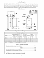
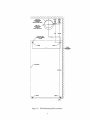
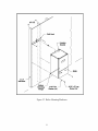
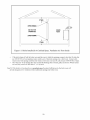
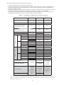
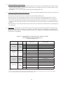
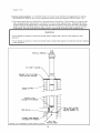
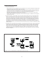
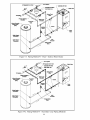
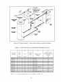
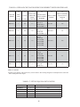
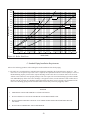
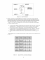
Table of Contents I. II. III. IV. V. VI. VII. VIII. IX. X. XI. XII. XIII. XIV. XV. Product Description Specifications Before Installing Locating The Boiler Mounting The Boiler Air For Ventilation Venting A. Vent System Design B. Removing An Existing Boiler From Common Chimney C. Assembly of Crown 60/100mm Concentric Venting D. Assembly of Crown 80/125mm Concentric Venting E. Assembly of Stainless Steel Venting F. Condensate Trap and Drain Gas Piping System Piping General System Piping Precaution System Design Standard Piping Installation Requirements Piping For Special Situations Wiring Start-up and Checkout Operation Service and Maintenance Troubleshooting Parts Appendix A: Optional Method for Retrofitting BWC Boilers into Existing Circulator Zone Systems Appendix B: Special Requirements For Side-Wall Vented Appliances In The Commonwealth of Massachusetts 1 2 2 3 3 6 9 11 11 21 22 26 35 40 42 43 43 43 50 51 53 57 63 68 70 73 85 87 III Before Installing 1) Safe, reliable operation of this boiler depends upon installation by a professional heating contractor in strict accordance with this manual and the authority having jurisdiction. • • In the absence of an authority having jurisdiction, installation must be in accordance with this manual and the National Fuel Gas Code, ANSI Z223.1. In Canada, installation must be in accordance with the B149.1 Installation Code Where required by the authority having jurisdiction, this installation must conform to the Standard for Controls and Safety Devices for Automatically Fired Boilers (ANSI/ASME CSD-1). 2) BWC boilers utilize aluminum heat exchangers constructed, tested, and stamped in accordance with ASME Boiler and Pressure Vessel Code Case 2382. Some jurisdictions which require ASME boiler construction do not recognize this Code Case and may not approve the installation of an aluminum boiler. Consult the authority having jurisdiction before installing this boiler. 3) Read Section VII to verify that the maximum combustion air and exhaust pipe lengths will not be exceeded in the planned installation. Also verify that the vent terminal can be located in accordance with Section VII. 4) Make sure that the boiler is correctly sized: • • • • For heating systems employing convection radiation (baseboard or radiators), use an industry accepted sizing method such as the I=B=R Heat Loss Calculation Guide (Pub. #H21 or #H22) published by the Hydronics Institute in Berkely Heights, NJ. For new radiant heating systems, refer to the radiant tubing manufacturer’s boiler sizing guidelines. For systems including a Crown Mega-Stor indirect water heater, size the boiler to have either the DOE Heating Capacity required for the Mega-Stor or the net rating required for the heating system, whichever results in the larger boiler. For systems that incorporate other indirect water heaters, refer to the indirect water heater manufacturer’s instructions for boiler output requirements. 5) Make sure that the boiler received is configured for the correct gas (natural or LP). 6) Make sure that the boiler is configured for use at the altitude at which it is to be installed. NOTICE This product must be installed by a licensed plumber or gas fitter when installed within the Commonwealth of Massachusetts. See Appendix A for additional important information about installing this product within the Commonwealth of Massachusetts. IV Locating the Boiler 1) Observe the minimum clearances shown in Figure 4.1. These clearances apply to both combustible and noncombustible materials. Observe the minimum clearances to combustibles for vent pipe shown in Table 4.2. 2) Note the recommended service clearances in Figure 4.1. These service clearances are recommended, but may be reduced to the combustible clearances provided: a. b. Access to the front of the boiler is provided through a door. Access is provided to the condensate trap and transformer located underneath the boiler. 3) When the boiler is installed on the floor using the optional pedestal kit, the boiler may be installed on a noncarpeted combustible surface. 4) The relief valve must be installed in the factory specified location. 3 Table 4.2: Clearances From Vent Piping To Combustible Construction TYPE OF VENT PIPE PIPE DIRECTION ENCLOSURE MINIMUM CLEARANCE TO COMBUSTIBLE MATERIAL 80/125 and 60/100mm CONCENTRIC VENTING VERTICAL OR HORIZONTAL ENCLOSED ON ALL FOUR SIDES 0” HEAT FAB SAF-T VENT PROTECH FASNSEAL Z-FLEX Z-VENT III METAL-FAB CORR/GUARD VERTICAL OR HORIZONTAL AT LEAST ONE SIDE OPEN, COMBUSTIBLE MATERIAL ON A MAXIMUM OF THREE SIDES HEAT FAB SAF-T VENT PROTECH FASNSEAL Z-FLEX Z-VENT III METAL-FAB CORR/GUARD HORIZONTAL OR VERTICAL WITH OFFSETS ENCLOSED ON ALL FOUR SIDES HEAT FAB SAF-T VENT PROTECH FASNSEAL Z-FLEX Z-VENT III METAL-FAB CORR/GUARD VERTICAL WITH NO OFFSETS ENCLOSED ON ALL FOUR SIDES 5 1” 2-1/2” 2-1/2” VI Air for Ventilation WARNING OUTDOOR COMBUSTION AIR MUST BE PIPED TO THE AIR INTAKE. NEVER PIPE COMBUSTION AIR FROM AREAS CONTAINING CONTAMINATES SUCH AS SWIMMING POOLS AND LAUNDRY ROOM EXHAUST VENTS. CONTAMINATED COMBUSTION AIR WILL DAMAGE THE BOILER AND MAY CAUSE PROPERTY DAMAGE, PERSONAL INJURY OR LOSS OF LIFE. Air for combustion must always be obtained directly from outdoors, however sufficient air for ventilation must still be provided in the boiler room. Air for ventilation is required to keep various boiler components from overheating and is always obtained from indoors. To ensure an adequate ventilation air supply, perform the following steps: Step 1: Determine whether the boiler is to be installed in a confined space - A confined space is defined by the National Fuel Gas Code as having a volume less than 50 cubic feet per 1000 BTU/hr input of all appliances installed in that space. To determine whether the boiler room is a confined space: 1) Total the input of all appliances in the boiler room in thousands of BTU/hr. Round the result to the next highest 1000 BTU/hr. 2) Find the volume of the room in cubic feet. The volume of the room in cubic feet is: Length (ft) x width (ft) x ceiling height (ft) In calculating the volume of the boiler room, consider the volume of adjoining spaces only if no doors are installed between them. If doors are installed between the boiler room and an adjoining space, do not consider the volume of the adjoining space, even if the door is normally left open. 3) Divide the volume of the boiler room by the input in thousands of BTU/hr. If the result is less than 50, the boiler room is a confined space. Example: A BWC120 and a water heater are to be installed in a room measuring 6ft – 3 in x 7ft with an 8 ft ceiling. The water heater has an input of 30000 BTU/hr: Total input in thousands of BTU/hr = (120000 BTU/hr + 30000 BTU/hr) / 1000 = 150 MBTU/hr Volume of room = 6.25 ft x 7 ft x 8 ft = 350 ft3 350/150 = 2.33. Since 2.33 is less than 50, the boiler room is a confined space. Step 2a: If the boiler is to be placed in a confined space, provide two openings into the boiler room, one near the floor and one near the ceiling. The top edge of the upper opening must be within 12” of the ceiling and the bottom edge of the lower opening must be within 12” of the floor (Fig 6.1). The minimum opening dimension is 3 inches. • • If the BWC boiler is the only gas-burning appliance in the boiler room, these openings must each have a minimum free area of 100 square inches. If other gas-burning appliances are in the boiler room, size the openings in accordance with the appliance manufacturer’s instructions or the National Fuel Gas Code. Minimum opening free area is 100 square inches even if opening requirements for other appliances are less. 9 VII Venting WARNING FAILURE TO VENT THIS BOILER IN ACCORDANCE WITH THESE INSTRUCTIONS COULD CAUSE FLUE GAS TO ENTER THE BUILDING RESULTING IN SEVERE PROPERTY DAMAGE, PERSONAL INJURY, OR DEATH: * Use only vent systems and materials explicitly permitted by Crown for use with this boiler. * Do not attempt to mix components from different approved vent systems. * Do not obtain combustion air from within the building. * Do not install a barometric damper or drafthood on this boiler. CAUTION Moisture and ice may form on the surfaces around the vent termination. To prevent deterioration, surfaces should be in good repair (sealed, painted, etc.). A. Vent System Design There are four basic ways to vent this boiler: • Horizontal (“Side Wall”) Concentric Venting - Vent system exits the building through an outside wall. Concentric venting consists of a “pipe within a pipe”. Flue gas exits the building through the inner pipe and combustion air is drawn into the boiler through the space between the inner and outer pipe. • Horizontal (“Side Wall”) Twin Pipe Venting - Vent system exits the building through an outside wall. Combustion air and flue gas are routed between the boiler and outdoors using separate pipes. • Vertical Concentric Venting - Vent system exits the building through the roof. Concentric venting consists of a “pipe within a pipe”. Flue gas exits the building through the inner pipe and combustion air is drawn into the boiler through the space between the inner and outer pipe. • Vertical Twin Pipe Venting - Vent system exits the building through a roof. Combustion air and flue gas are routed between the boiler and outdoors using separate pipes. All of these systems are considered “direct vent” because in all of them air for combustion is drawn directly from the outdoors into the boiler. A description of all of these venting options are shown in Tables 7.1 and 7.9. For clarity, these vent options are numbered from 1 to 6. One of the vent option columns in Tables 7.1 or 7.9 must match the planned vent and air intake system exactly. In addition, observe the following guidelines: 1) Approved vent systems - Use only one of the approved vent systems shown in Tables 7.4 or 7.5. These vent systems fall into two basic categories: • Concentric Vent System - The standard boiler is supplied with a concentric vent system having a maximum usable length of 25” (Figure 1.1). For longer runs, additional straight lengths and elbows are available from Crown. In some cases, larger diameter concentric pipe must be used. Each Crown concentric vent component consists of an inner pipe of polypropylene and the outer pipe of steel. Integral gaskets on each concentric fitting provide a gas tight seal. A list of all Crown concentric vent components is shown in Table 7.4. In this manual, concentric pipe sizes are called out in terms of the inner and outer pipe nominal diameters in millimeters. For example, “60/100mm” pipe consists of a 60mm exhaust pipe inside a 100mm diameter outer pipe. • Twin Pipe Vent Systems - Approved vent systems are made of a special stainless steel alloy (AL29-4C) for protection against corrosive flue gas condensate. They are designed to provide a gas tight seal at all joints and seams so that flue gas does not enter the building. Each approved vent system has a unique method for installation - do not attempt to mix components from different vent systems. A list of approved twin pipe vent systems is shown in Table 7.5. Note that a special vent collar (Crown PN 230510) is required if the boiler is to be vented with one of the approved stainless vent systems. 11 2) Maximum Vent and Air Intake Lengths - The maximum length of the vent air intake piping depends upon the vent option selected and the boiler size. See Table 7.1 or 7.9 for the maximum vent length. In horizontal vent systems, the lengths shown in Table 7.1 are in addition to the first standard elbow on top of the boiler. For vertical vent systems, the maximum vertical vent lengths shown in Table 7.9 are in addition to two standard radius elbows. If more elbows are desired, the maximum allowable vent length must be reduced by the amount shown in Table 7.8 for each additional elbow used. Termination fittings are never counted, although the length of the concentric terminal section is counted. Example: A 60/100mm concentric vent system is planned for a horizontally vented BWC120 which has the following components: 80/125 x 60/100mm Reducing Elbow (supplied with the boiler) 5ft Straight Pipe 90 elbow 1-1/2ft Straight Pipe 45Elbow Uncut Terminal Section (supplied with the boiler) The Vent Option #1 column in Table 7.1 describes a horizontal direct vent system using 60/100mm concentric vent pipe. From this column, we see that a BWC120 may have a vent length of up to 18ft. The 90 degree reducing elbow is not considered. The length of the terminal section (not including the plastic terminal itself) is approximately 22 1/2” (1.9ft) installed. From Table 7.8, we see that the equivalent length of the 60/100mm elbow is 4.5ft and that the equivalent length of the 45 degree elbow is 4ft. The total equivalent length of the planned venting system is therefore: 5ft (Straight ) + 4.5ft (90 Elbow) + 1.5ft (Straight ) + 4 ft (45 Elbow) + 1.9ft (Uncut Terminal Section) = 16.9ft. Since Table 7.1 shows a maximum allowable vent length of 18ft, the planned vent system length is acceptable. 3) Minimum Vent and Air Intake Lengths - Observe the minimum vent lengths shown in tables 7.1 and 7.9. 4) Permitted Terminals for Horizontal Venting: • Vent Option 1 - The 60/100mm concentric vent terminal is supplied with the boiler as part of the standard vent system. • Vent Option 2 - The exhaust terminal is Crown PN 230511. The air intake fitting is a 90 degree elbow with a rodent screen supplied by the installer. This elbow is made out of the same material as the rest of the air inlet system (either galvanized or PVC) and is installed as shown in Figure 7.3. • Vent Option 3 - Two terminals are permitted: a) 80/125mm Concentric Vent Terminal (Crown PN 230531) b) 80/125mm Snorkel Terminal (Crown PN 230540) . This terminal allows the vent system to exit the building close to grade and go up the exterior wall far enough to provide adequate clearance between the terminal itself and the snow line (Figure 7.7). 5) Horizontal Vent and Air Intake Terminal Location - Observe the following limitations on the vent terminal location (also see Figures 7.6, 7.7). When locating a concentric terminal, observe the limitations outlined below for “vent terminals”. • Vent terminals must be at least 1 foot from any door, window, or gravity inlet into the building. • For twin pipe terminals, maintain the correct clearance and orientation between the vent and air intake terminals. The vent and air intake terminals must be at the same height and their center lines must be between 12 and 36 inches apart. Both terminals must be located on the same wall. • The bottom of all terminals must be at least 12” above the normal snow line. In no case should they be less than 12” above grade level. • The bottom of the vent terminal must be at least 7 feet above a public walkway. • Do not install the vent terminal directly over windows or doors. • The bottom of the vent terminal must be at least 3 feet above any forced air inlet located within 10 feet. • USA Only: A clearance of at least 4 feet horizontally must be maintained between the vent terminal and gas meters, electric meters, regulators, and relief equipment. Do not install vent terminal over this equipment. In Canada, refer to B149.1 Installation Code for clearance to meters, regulators and relief equipment. • Do not locate the vent terminal under decks or similar structures. • Top of vent terminal must be at least 5 feet below eves, soffits, or overhangs. Maximum depth of overhang is 3 ft. 12 Horizontal Terminal Clearance Requirements (continued): • Vent terminal must be at least 6 feet from an inside corner. • Under certain conditions, water in the flue gas may condense, and possibly freeze, on objects around the vent terminal including on the structure itself. If these objects are subject to damage by flue gas condensate, they should be moved or protected. • If possible, install the vent and air intake terminals on a wall away from the prevailing wind. Reliable operation of this boiler cannot be guaranteed if these terminals are subjected to winds in excess of 40 mph. • Air intake terminal must not terminate in areas that might contain combustion air contaminates, such as near swimming pools. See Section IV for more information on possible contaminates. TABLE 7.1: SUMMARY OF HORIZONTAL VENTING OPTIONS VENT OPTION # 1 CLASSIFICATION USED IN THIS MANUAL 2 HORIZONTAL CONCENTRIC HORIZONTAL TWIN PIPE 3 HORIZONTAL CONCENTRIC ILLUSTRATED IN FIGURE 7.2 7.3 7.2 VENT PIPE PENETRATION THROUGH STRUCTURE WALL WALL WALL AIR INTAKE PIPE PENETRATION THROUGH STRUCTURE WALL WALL WALL 60/100 mm CONCENTRIC 3” 80/125 mm CONCENTRIC VENT PIPE SIZE VENT BWC070 32ft 100ft 100ft 32ft 100ft 100ft BWC120 18ft 100ft 100ft 100ft 100ft 100ft 100ft BWC070 32ft BWC090 32ft 100ft 100ft BWC120 18ft 100ft 100ft 100ft 100ft VENT BWC151 BWC070 10in 10in 10in BWC090 10in 10in 10in BWC120 10in 10in 10in 10in 10in BWC151 INLET MINIMUM LENGTH 3” BWC090 BWC151 INLET MAXIMUM LENGTH AIR INTAKE PIPE SIZE BWC070 10in 10in 10in BWC090 10in 10in 10in BWC120 10in 10in 10in 10in 10in BWC151 VENT TERMINAL 60/100 mm CONCENTRIC AIR INTAKE TERMINAL VENT MATERIAL AIR INTAKE MATERIAL CROWN 60/100mm VENT COMPONENTS SHOWN IN TABLE 7.4a (Note #1) CROWN #230511 3” 90 ELBOW Crown 230531 CONCENTRIC or 230540 SNORKEL APPROVED STAINLESS STEEL VENT SYSTEM SHOWN IN TABLE 7.5 CROWN 80/125mm VENT COMPONENTS SHOWN IN TABLE 7.4b GALVANIZED OR PVC Note #1: In Vent Option #1, the 80/125mm concentric straight section (PN 230515) shown in Table 7.4a may be used between the boiler and the first 80/125 x 60/100 reducing elbow. If this is done, the overall maximum vent length is still restricted to that shown for Vent Option #1 in Table 7.1 above. 13 TABLE 7.4a: CROWN CONCENTRIC 60/100 VENT COMPONENTS (VENT OPTION 1) CROWN PN DESCRIPTION SIZE USED ON VENT OPTION # COMMENTS 230521 80/125 x 60/100mm REDUCING ELBOW 80/125 x 60/100mm 1 INCLUDED WITH STANDARD BWC070/090/120 230520 TERMINAL SECTION 60/100mm 1 INCLUDED WITH STANDARD BWC070/090/120 230522 WALL GROMMET 60/100mm 1 INCLUDED WITH STANDARD BWC070/090/120 230505 39” STRAIGHT 60/100mm 1 OPTIONAL - MAY NOT BE CUT 230504 78” STRAIGHT 60/100mm 1 OPTIONAL - MAY NOT BE CUT 230506 19 1/2” STRAIGHT 60/100mm 1 OPTIONAL - CAN BE CUT 230507 90 DEGREE ELBOW 60/100mm 1 OPTIONAL 230508 45 DEGREE ELBOW 60/100mm 1 OPTIONAL 230515 39” STRAIGHT 80/125mm 1 OPTIONAL - CAN BE CUT (Note #1) Note #1: On 60/100mm vent systems, this may only be used between the boiler and the first 80/125 x 60/100 Reducing elbow (see text). TABLE 7.4b: CROWN CONCENTRIC 80/125 VENT COMPONENTS (VENT OPTIONS 3,6) CROWN PN DESCRIPTION SIZE USED ON VENT OPTION # 230527 90 DEGREE EL (STANDARD) 80/125mm 3,6 230528 90 DEGREE EL (SWEEP) 80/125mm 3,6 COMMENTS 230526 45 DEGREE EL 80/125mm 3,6 230517 19 1/2” STRAIGHT 80/125mm 3,6 CAN BE CUT 230515 39” STRAIGHT 80/125mm 3,6 CAN BE CUT 230518 39” STRAIGHT 80/125mm 3,6 MAY NOT BE CUT 230519 78” STRAIGHT 80/125mm 3,6 MAY NOT BE CUT 230525 TELESCOPING STRAIGHT 80/125mm 3,6 ADJUSTABLE FROM 12-1/2” TO 16-1/2 230531 HORIZONTAL TERMINAL 80/125mm 3 230540 SNORKEL KIT 80/125mm 3 (NOTE #1) (NOTE #2) 230532 VERTICAL TERMINAL 80/125mm 6 230533 FLAT ROOF FLASHING 80/125mm 6 230535 SLOPED ROOF FLASHING 80/125mm 6 (NOTE #3) 230530 SUPPORT ELBOW WITH CHIMNEY CHASE BRACKET 80/125mm 6 (NOTE #4) 230536 SUPPORT BAND 80/125mm 3,6 Table 7.4b Notes: 1) Snorkel kit includes parts needed to offset terminal on exterior wall by up to 46”. 2) Vertical terminal can be used with either of the roof flashings listed beneath it. 3) Sloped roof flashing suitable for roof angles between 25 and 45 degrees. 4) Used at base of vertical run inside unused masonry chimney. 15 6) Permitted Terminals for Vertical Venting • Vent Option 5 - A straight termination is installed in the end of the vent pipe. Vent manufacturer part numbers for these screens are shown in Table 7.5. The air inlet terminal consists of a 180 degree elbow (or two 90 degree elbows) with a rodent screen as shown in Figure 7.10. • Vent Option 6 - Use Crown PN 230532 with the appropriate flashing (Table 7.4b) 7) Vertical Vent Terminal Locations (Vent Options 5,6) - Observe the following limitations on the location of all vertical vent terminals (see Figures 7.10, 7.11): • The top of the vent pipe must be at least 2 feet above any object located within 10 feet. • For Vent Option #5, the vertical distance between top of the vent and air inlet terminal openings must be at least 12”. • The bottom of the air inlet terminal must be at least 12” above the normal snow accumulation that can be expected on the roof. The terminal used in Vent Option #6 has a fixed distance above the storm collar of 19”. If a greater distance is needed to provide the clearance above the snow line, build a chase on the roof and mount the vertical terminal on top of the chase. • For Vent Option #5, the air intake terminal must be located on the roof and must be no further than 24” horizontally from the exhaust pipe. 8) Wall thimbles – Wall thimbles are required where single wall vent pipe passes through combustible walls with less than the required clearance shown in Table 4.2 or as required by local codes. Stainless vent manufacturer’s wall thimble part numbers are shown in Table 7.5. Note that concentric vent has a “zero” clearance to combustibles and therefore does not require the use of wall thimbles. TABLE 7.5: PERMISSIBLE STAINLESS STEEL VENT SYSTEMS AND PRINCIPLE VENT COMPONENTS (VENT OPTIONS 2, 5) MANUFACTURER VENT SYSTEM HEAT FAB SAF-T VENT EZ SEAL PROTECH SYSTEMS INC. Z-FLEX METAL-FAB FASNSEAL SVE SERIES III (“Z-VENT III”) CORR/ GUARD SIZE COMPONENT PART NUMBER 3 BOILER COLLAR CROWN 230510 3 WALL THIMBLE HEAT FAB 7393, 7393GCS, 5391CI 3 HORIZONTAL TERMINAL CROWN 230511 3 VERTICAL TERMINAL HEAT FAB 9392 3 BOILER COLLAR CROWN 230510 3 WALL THIMBLE FSWT3 3 HORIZONTAL TERMINAL 3 VERTICAL TERMINAL 3 BOILER COLLAR 3 WALL THIMBLE 3 HORIZONTAL TERMINAL 3 VERTICAL TERMINAL 3 BOILER COLLAR CROWN 230510 3 WALL THIMBLE CGSWWPK(3”) 3 HORIZONTAL TERMINAL CROWN 230511 3 VERTICAL TERMINAL CGSWHTM(3”) CROWN 230511 FSBS3 CROWN 230510 2SVSWTEF03 CROWN 230511 24SVSTPF03 NOTES: 1) See vent system manufacturer’s literature for other part numbers that are required such as straight pipe, elbows, firestops and vent supports. 2) Crown 230510 collar replaces factory-mounted concentric collar (Figure 7.16). 16 9) Pitch of Horizontal Piping - Pitch all horizontal piping so that any condensate which forms in the piping will run towards the boiler: • Pitch Crown horizontal concentric venting 5/8” per foot • Pitch Stainless steel venting 1/4” per foot. 10) Supporting Pipe - Vertical and horizontal sections of pipe must be properly supported: • Support Crown concentric venting near the female end of each straight section of pipe. Exception: Vertical runs of concentric pipe in an unused chinmey (Figure 7.36) need only be supported at the terminal and at the base of the run. • Support stainless steel venting as called for by the vent manufacturer’s instructions. FIGURE 7.7: SNORKEL TERMINAL CONFIGURATION 18 TABLE 7.8: VENT/ AIR INTAKE FITTING EQUIVALENT LENGTH VENT FITTING EQUIVALENT LENGTH (ft) 60/100mm 90° CONCENTRIC ELBOW 4.5 60/100mm 45° CONCENTRIC ELBOW 4.0 80/125mm 90° CONCENTRIC ELBOW 8.5 80/125mm 90° SWEEP CONCENTRIC ELBOW 5.5 80/125mm 45° CONCENTRIC ELBOW 3.0 80/125mm 90° CONCENTRIC SUPPORT ELBOW 8.5 3” SINGLE WALL 90° ELBOW 5.5 3” SINGLE WALL 45° ELBOW 4.0 TABLE 7.9: SUMMARY OF VERTICAL VENTING OPTIONS VENT OPTION # 5 CLASSIFICATION USED IN THIS MANUAL VERTICAL TWIN PIPE 6 VERTICAL CONCENTRIC ILLUSTRATED IN FIGURE 7.10 7.11 VENT PIPE PENETRATION THROUGH STRUCTURE ROOF ROOF AIR INTAKE PIPE STRUCTURE THROUGH STRUCTURE ROOF ROOF AIR INTAKE PIPE SIZE 3” INLET VENT INLET MINIMUM LENGTH VENT 3” MAXIMUM LENGTH VENT PIPE SIZE 80/125 mm CONCENTRIC BWC070 98ft 95ft BWC090 98ft 95ft BWC120 98ft 95ft BWC151 98ft 95ft BWC070 98ft 95ft BWC090 98ft 95ft BWC120 98ft 95ft BWC151 98ft 95ft BWC070 2ft 2ft BWC090 2ft 2ft BWC120 2ft 2ft BWC151 2ft 2ft BWC070 2ft 2ft BWC090 2ft 2ft BWC120 2ft 2ft 2ft 2ft BWC151 VENT TERMINAL STRAIGHT TERMINAL BY VENT SYSTEM MFR. (TABLE 7.5) 3” 180° ELBOW (FIGURE 7.10) AIR INTAKE TERMINAL VENT MATERIAL AIR INTAKE MATERIAL APPROVED STAINLESS STEEL VENT SYSTEM GALVANIZED OR PVC 19 CROWN #230532 CONCENTRIC TERMINAL (TABLE 7.4b) CROWN 80/125 mm VENT COMPONENTS SHOWN IN TABLE 7.4b FIGURE 7.10: VERTICAL TWIN PIPE VENT SYSTEM (VENT OPTION 5) FIGURE 7.11: VERTICAL CONCENTRIC VENT SYSTEM (VENT OPTION 6) 20 B. Removing an Existing Boiler From a Common Chimney Read this only if the BWC boiler is replacing an existing boiler that is being removed from a common chimney. This section does not apply to the installation of a BWC boiler. In some cases, when an existing boiler is removed from a common chimney, the common venting system may be too large for the remaining appliances. At the time of removal of an existing boiler, the following steps shall be followed with each appliance remaining connected to the common venting system placed in operation, while the other appliances remaining connected to the common venting system are not in operation. (a) Seal any unused openings in the common venting system. (b) Visually inspect the venting system for proper size and horizontal pitch and determine there is no blockage or restriction, leakage, corrosion and other deficiencies which could cause an unsafe condition. (c) Insofar as practical, close all building doors and windows and all doors between the space in which all the appliances remaining connected to the common venting system are located and other spaces of the building. Turn on clothes dryers and any appliance not connected to the common venting system. Turn on any exhaust fans, such as range hoods and bathroom exhausts, so they will operate at maximum speed. Do not operate a summer exhaust fan. Close fireplace dampers. (d) Place in operation the appliance being inspected. Follow the lighting instructions. Adjust thermostat so the appliance will operate continuously. (e) Test for spillage at the draft hood relief opening after 5 minutes of main burner operation. Use the flame of a match or candle, or smoke from a cigarette, cigar, or pipe. (f) After it has been determined that each appliance remaining connected to the common venting system properly vents when tested as outlined above, return doors, windows, exhaust fans, fireplace dampers and any other gas-burning appliances to their previous condition of use. (g) Any improper operation of the common venting system should be corrected so the installation conforms with the National Fuel Gas Code, ANSI Z223.1. When re-sizing any portion of the common venting system, the common venting system should be re sized to approach the minimum size as determined using the appropriate tables in Part 11 of the National Fuel Gas Code, ANSI Z223.1. WARNING NEVER COMMON VENT A BWC BOILER WITH OTHER APPLIANCES. 21 C. Assembly of Crown 60/100mm Concentric Venting (IMPORTANT - Skip to Section D for 80/125mm Concentric Vent Assembly) WARNING Failure to follow the instructions could result in flue gas leakage into the combustion air or indoor air, resulting in unsafe or unreliable operation. • Do not lubricate concentric gaskets with anything other than water. • Do not attempt to cut any piping except as permitted in this section. When cutting these sections, make sure all cuts are square and allow for proper insertion. • Do not attempt to try to mix this concentric pipe with other venting systems. 1) Concentric vent components supplied with the boiler are packed inside the BWC070/090/120 carton and include the following: a) 80/125 x 60/100mm reducing elbow (Crown PN 230521). b) 60/100mm terminal section (straight section with a terminal and overall length of 27 3/4” (Crown PN 230520). c) Two (2) Rubber wall grommets (Crown PN 230522). 2) Unless the 80/125 straight riser (PN 230515) is used, start by attaching the reducing elbow to the boiler collar. To do so, remove the clamp from the large end of the reducing elbow and set aside. Apply a small amount of water to the brown gasket on the boiler collar. Push the elbow onto the boiler collar until the bead on the elbow contacts the top edge of the collar (Figure 7.20). 3) Reinstall the clamp removed in Step (2) so that the elbow is secured to the boiler collar. 4) If no additional sections of concentric pipe are required, attach the terminal section to the elbow. In most cases, it will need to be cut before doing so. Use the following procedure to cut the pipe: a) Measure distance “L” from the outside surface of the exterior wall to the end of the elbow as shown in Figure 7.21. b) Add 2-1/8” to distance “L”. Carefully mark this length on the pipe as shown in Figure 7.22. c) Press in the two tabs holding the plastic terminal in the terminal section (Figure 7.22). Carefully pull out the terminal and the inner pipe. d) Cut the outer pipe only at the point marked in Step (b) using aviation shears, a hacksaw, or an abrasive wheel cutter. Be careful to cut the pipe square. De burr the cut end with a file or emery cloth. e) Cut the plastic inner pipe so that it will protrude 3/8” beyond the outer pipe when reinstalled in the terminal section (Figure 7.23). Use a fine tooth hacksaw or a PVC saw to cut the plastic pipe and be careful to cut the pipe square. De burr the cut edge of the plastic pipe with a file, razor blade, or fine sandpaper. f) Reinstall the inner pipe in the terminal section. Slip the outside wall grommet over the terminal section and position so that it covers the joint between the outer pipe and the terminal (Figure 7.24). g) Make a mark on the terminal section 1” from the cut end of the outer pipe as shown in Figure 7.24. h) Pass the terminal section through the wall from the outside. Push the remaining wall grommet over the terminal section on the inside of the wall. Push the terminal section into the elbow until the mark made in Step (g) is no longer visible. If necessary, the brown gasket in the inner pipe may be lubricated with a few drops of water. i) The terminal section must be attached to the elbow with a single #10 x 1/2” sheet metal screw ( not supplied) at the top of the elbow. Drill a 1/8” hole in the location shown in Figure 7.25. Use a short drill bit or a drill stop to ensure that the drill bit does not penetrate the pipe by more than 3/8”. Install a #10 x 1/2” screw in this hole. Do not use a screw longer than 1/2” long. j) If not already done, make sure that both wall grommets are firmly against the interior and exterior wall surfaces. Seal any cracks or other openings near the terminal through which exhaust could enter the building. 5) If additional pieces of pipe are used, install them starting at the boiler elbow. Support each section of straight pipe at its female end. 22 D. Assembly of Crown 80/125mm Concentric Venting (IMPORTANT - See Section C for 60/100mm Concentric Vent Assembly) WARNING Failure to follow the instructions could result in flue gas leakage into the combustion air or indoor air, resulting in unsafe or unreliable operation. • Do not lubricate concentric gaskets with anything other than water. • Do not attempt to cut any piping except as permitted in this section. When cutting these sections, make sure all cuts are square and allow for proper insertion. • Do not attempt to try to mix this concentric pipe with other venting systems. 1) When BWC070, BWC090, or BWC120 boilers are vented using 80/125 venting, the 60/100 terminal section and reducing elbow supplied with the boiler are not used. The components listed in Table 7.4b are required for 80/125mm installations and are not supplied. The BWC151 is supplied with the following 80/125 components: a) b) 80/125 Standard Radius Elbow 80/125 Terminal Section Before starting assembly of an 80/125 vent system, make sure that the planned installation is in accordance with the “Vent System Design” Section of this manual and that all required 80/125mm vent components are on hand. Any components not supplied with the boiler are available through Crown distributors. FIGURE 7.30a: CUTTABLE STRAIGHT SECTION FIGURE 7.30b: NON CUTTABLE STRAIGHT SECTION 26 3) Assembly of Metal-Fab Corr/Guard Vent System: a) Corr/Guard General Notes: • Do not cut Corr/Guard vent components. • Refer to Corr/Guard installation instructions for proper methods of support. • Orient Corr/Guard components so that the males ends of all fittings point in the direction of the boiler. b) Start assembly of the vent system at the boiler. Remove the hose clamp shipped on the BWC vent collar. Bend the three hose clamp tabs on this collar outward slightly. c) Clean the exterior of the male end of the first piece of pipe and the inside of the vent collar on the boiler. Remove dirt, grease, and moisture from the surfaces to be sealed. Dry surfaces or allow to dry thoroughly. d) On the male end of the pipe, apply a ¼” wide bead of silicone approximately 1/2” from the end of the pipe (Fig 7.47). e) Insert the male end of the pipe into the boiler vent collar until it bottoms out. f) Apply an additional bead of silicone over the outside of the joint and smooth out. g) Replace and tighten the clamp on the vent collar. h) Assemble remaining Corr/Guard components in accordance with the Corr/Guard installation instructions. i) Allow the silicone to cure per the silicone manufacturer’s instructions before operating the boiler. FIGURE 7.47: CORR/GUARD CONNECTION TO VENT COLLAR 36 4) Assembly of Z-Flex Z-Vent III: a) General Notes: • Non-expanded ends of SVE Series III piping sections may be cut using aviation snips or a 24 thread per inch hacksaw. File or sand the cut end smooth before assembling. Expanded ends may be cut to adapt the SVE series III to the vent collar. See the following instructions. • Support horizontal piping sections at intervals of 48” or less. • Vertical venting systems must be supported by at least one Z-Flex fire stop. An additional vertical support is required after any offset and as required by the Z-Vent III installation instructions. b) Start assembly of the vent system at the boiler. Remove the hose clamp shipped on the BWC vent collar. Bend the three hose clamp tabs on this collar outward slightly. c) Clean the exterior of the male end of the first piece of pipe and the inside of the vent collar on the boiler. Remove dirt, grease, and moisture from the surfaces to be sealed. Dry surfaces or allow to dry thoroughly. d) On the male end of the pipe, apply a ¼” wide bead of high temperature silicone approximately ½ inch from the male end of the pipe. Apply ¼” beads of silicone along both sides of the longitudinal seam (Fig. 7.48). e) Insert the male end of the pipe into the boiler vent collar until it bottoms out. f) Apply an additional bead of silicone over the outside of the joint and smooth out. g) Replace and tighten the clamp on the vent collar. h) The female end of each Z-Vent III component has a silicone sealing gasket. Examine all vent components to insure that the gasket integrity has remained during shipping. Gaskets must be in the proper position or flue gas could leak resulting in carbon monoxide poisoning. i) Align the second piece of pipe with the first and push them together as far as they will go, but not less than 13/4”. j) Tighten gear clamp to a minimum torque of 40 in-lbs and a maximum of 50 in-lbs. k) Repeat Steps (h) – (j) for the remaining Z-Vent III components. l) In horizontal vent systems, a locking band or gear clamp must be used at either side of the wall penetration to prevent shifting of the vent system in and out of the wall. This applies to both combustible and non-combustible walls. n) Allow the silicone to cure per the silicone manufacturer’s instructions before operating the boiler. FIGURE 7.48: Z-VENT III CONNECTION TO VENT COLLAR 37 5) Assembly of Heat Fab Saf-T Vent EZ Seal: a) Saf-T Vent General Notes: • These instructions cover the installation of Saf-T Vent EZ Seal. Saf-T Vent EZ Seal piping has integral gaskets installed in the female ends of the pipe which seal the joints. • In general, Saf-T Vent pipe sections may not be cut. Exceptions to this are the Saf-T Vent slip connector and connections to the boiler vent collar.In these cases, use a sharp pair of aviation snips, an abrasive cut-off, or a plasma cutter. See the Saf-T Vent instructions for information on cutting the slip connector. • Orient Saf-T Vent components so that the arrows on the piping labels are in the direction of flue gas flow. • Support horizontal piping sections at intervals of 6 feet or less. • Vertical venting systems must be supported by at least one Heat Fab support. An additional vertical support is required after any offset. b) Connection to Boiler – Start assembly of the vent system at the boiler. Remove the hose clamp shipped on the BWC vent collar. Bend the three hose clamp tabs on this collar outward slightly. Cut the “male spigot” off of the first piece of pipe (Fig 7.49). If necessary, crimp the cut end of the pipe so that it can be inserted at least 1” into the collar. Clean the exterior of the male end of the first piece of pipe and the inside of the vent collar on the boiler with an alcohol pad. On the male end of the pipe, apply a ¼” wide bead of high temperature silicone approximately ½ inch from the male end of the pipe. Also apply a ¼” bead of silicone along the first 2 ½” of the longitudinal weld. Insert the male end of the pipe into the boiler vent collar until it bottoms out. Apply an additional bead of silicone over the outside of the joint and smooth out (Fig 7.49). Replace and tighten the clamp on the vent collar. c) Assembly of Saf-T Vent EZ Seal Vent Components - Clean the male end of the next piece of pipe with an alcohol pad and make sure that it is free of burrs. Check the female end of the first piece of pipe to make sure that the gasket is in place and is undamaged. Using a slight twisting motion, insert the male end of the second fitting into the female end of the first fitting, taking care not to dislodge or cut the factory gasket. In extremely arid conditions, it may be easier to assemble these fittings if the gasket is moistened with water prior to assembly. Bend the locking tabs over the locking ring on the adjacent piece of pipe. Repeat these steps for the remaining Saf-T-Vent components. FIGURE 7.49: SAF-T VENT EZ SEAL CONNECTION TO VENT COLLAR 38 8) Installation of Vertical Exhaust Terminal - Use the terminal supplied by the vent system manufacturer shown in Table 7.5. Attach to the vent system, following the assembly instructions in this manual for the stainless vent system being used. 9) Assembly of the Air Intake System and Air Intake Terminals: a) Assemble the air intake system using either galvanized or PVC pipe. b) If PVC piping is used, use PVC cement to assemble the PVC intake system components. c) If galvanized piping is used, use at least two sheet metal screws per joint. Seal the outside of all joints. d) 3” galvanized smoke pipe will fit inside the inlet collar on the boiler. Depending upon the exact OD of the pipe used, it may be necessary to crimp this pipe. Secure with a single #10 sheet metal screw through the hole in the inlet collar and seal the outside of the joint with silicone. If PVC is used for the intake system, use a short piece of 3” galvanized pipe to connect the PVC to the boiler. Silicone the outside of the joint between the PVC and galvanized pipe. e) Horizontal intake terminal is a 90 degree elbow pointing down. Elbow should protrude the same distance from the wall as the exhaust terminal. f) Vertical air intake terminal consists of a 180 degree bend (composed of two 90 degree elbows) as shown in Figure 7.10. g) Install a rodent screen (not supplied) in the inlet terminal. Use a screen having 1/2” (2 x 2) or larger mesh. F. Condensate Trap and Drain Line All condensate which forms in the boiler or vent system collects in the sump under the heat exchanger and leaves the boiler through the condensate trap. This trap allows condensate to drain from the sump while retaining flue gases in the boiler. The trap is supplied loose and must be installed as shown in Figure 7.51. A length of drain hose is supplied with the boiler and is connected to the trap as shown in Figure 7.51. Note the following when disposing of the condensate: a) If the condensate drain line must be extended, construct the extension from PVC or CPVC pipe. Insert the hose provided with the boiler into the end of the extension as shown in Figure 7.51. b) Condensate is slightly acidic. Do not use metallic pipe or fittings in the condensate drain line. Do not route the drain line through areas that could be damaged by leaking condensate. c) Some jurisdictions may require that the condensate be neutralized before being disposed of. Dispose of condensate in accordance with local codes. d) Do not route, or terminate, the condensate drain line in areas subjected to freezing temperatures. e) If the point of condensate disposal is above the trap, it will be necessary to use a condensate pump to move the condensate to the drain. In such cases, select a condensate pump that is approved for use with condensing furnaces. If overflow from this pump would result in property damage, select a pump with an overflow switch and use this switch to shut down the boiler. Alternatively, if heat is a necessity, use the overflow switch to trigger an alarm. f) Do not attempt to move the trap from the location shown in Figure 7.51. Do not attempt to substitute another trap for the one provided with the boiler. g) The vent shown in Figure 7.51 must be left open for the trap to work properly. WARNING FAILURE TO INSTALL THE CONDENSATE TRAP AND CONDENSATE DRAIN IN ACCORDANCE WITH THE ABOVE INSTRUCTIONS COULD CAUSE FLUE GAS TO ENTER THE BUILDING, RESULTING IN PERSONAL INJURY OR DEATH. CAUTION BOILER CONDENSATE IS CORROSIVE. ROUTE CONDENSATE DRAIN LINE IN A MANNER SUCH THAT ANY CONDENSATE LEAKAGE WILL NOT CAUSE PROPERTY DAMAGE. 40 IX System Piping A. General System Piping Precautions WARNING INSTALL BOILER SO THAT THE GAS IGNITION SYSTEM COMPONENTS ARE PROTECTED FROM WATER (DRIPPING, SPRAYING, RAIN, ETC) DURING APPLIANCE OPERATION AND SERVICE (CIRCULATOR REPLACEMENT, ETC). CAUTION THE HEAT EXCHANGER USED IN THE BWC IS MADE FROM A SPECIAL ALUMINUM ALLOY. FAILURE TO TAKE THE FOLLOWING PRECAUTIONS COULD RESULT IN SEVERE BOILER DAMAGE. • BEFORE CONNECTING BOILER, MAKE SURE THAT THE SYSTEM IS FREE OF SEDIMENT, FLUX AND ANY RESIDUAL BOILER WATER ADDITIVES. FLUSH THE SYSTEM IF NECESSARY TO ENSURE THAT THESE CONTAMINATES ARE REMOVED. • DO NOT CONNECT THIS BOILER TO A SYSTEM THAT IS SUBJECT TO REGULAR ADDITIONS OF MAKEUP WATER OR ONE WHICH EMPLOYS RADIANT TUBING WITHOUT AN OXYGEN BARRIER. • DO NOT ADD ANTIFREEZE OR OTHER BOILER WATER TREATMENT CHEMICALS EXCEPT THOSE LISTED IN PART XI OF THIS MANUAL. • MAINTAIN THE PRESSURE IN THE BOILER AT A MINIMUM OF 12 PSI. • DESIGN SYSTEM TO ENSURE THAT THE FLOW FALLS WITHIN THE LIMITS CALLED FOR IN TABLE 9.1. B. System Design Proper operation of the BWC boiler requires that the water flow through the boiler remain within the limits shown in Table 9.1 any time the burner is firing. Failure to maintain the flow within these limits could result in erratic operation or premature boiler failure. There are two basic methods that can be used to pipe the BWC boiler. Method #1 is almost always preferred. The instructions on the following pages describe these methods for piping BWC boilers and explain how to size the circulator and piping. Additional information on hydronic system design may be found in Installation of Residential Hydronic Systems (Pub. #200) published by the Hydronics Institute in Berkeley Heights, NJ. TABLE 9.1: FLOW REQUIREMENTS THROUGH BOILER BOILER MODEL BWC070 BWC090 BWC120 BWC151 MIN. REQUIRED FLOW (GPM) 4.0 4.0 4.5 6.0 43 MAX. ALLOWABLE FLOW (GPM) 9.0 9.0 12.0 15.0 TABLE 9.6: PIPE AND CIRCULATOR SIZING FOR INDIRECT WATER HEATER LOOP BOILER MODEL (a) (b) (c) PIPE SIZE FLOW MAX. I.W.H. PRESSURE DROP (in NPT) (GPM) (ft HEAD) BWC070 1 6.0 1.7 BWC090 1 8.0 3.0 BWC120 1 8.0 3.0 BWC120 1 8.0 5.0 BWC151 1 8.0 3.0 BWC151 1 8.0 5.0 (d) (e) (f) CROWN INDIRECT WATER HEATERS CIRCULATOR MODEL I.W.H. LOOP MAX EQUIVALENT LENGTH (ft) MS-26 (*) MS-40 (*) MSH-40H (*) MT040GBR (*) MS-26 MS-40 (*) MSH-40H MT040GBR (*) MS-26 MS-40 MSH-40H MT040GBR MT050GBR MT065GBR MT080GBR MSH-53H MS-26 MS-40 MSH-40H MT040GBR MT050GBR MT065GBR MT080GBR MS-53 MS-53H MSH-79(*) Taco 008 122 Taco 0014 78 Taco 0014 108 Taco 0014 70 Taco 008 49 Taco 0014 150 TABLE 9.6 NOTES: 1) Indirect water heaters with an asterisk (*) will not achieve their catalog rating due to inadequate boiler water flow and/or inadequate boiler output. TABLE 9.7: FITTING EQUIVALENT LENGTHS PIPE SIZE EQUIVALENT LENGTH (ft) 90 ELBOW 1 2.75 TURN IN TEE 1 5.50 RUN OF TEE 1 1.75 SWING CHECK GATE VALVE 1 1 7.00 0.60 FITTING 48 19.00 18.00 17.00 16.00 BWC120 15.00 BWC070, BWC090 14.00 13.00 BWC151 Head Loss (ft wc) 12.00 11.00 10.00 9.00 8.00 7.00 6.00 5.00 4.00 3.00 2.00 1.00 0.00 4 5 6 7 Figure 9.9: Boiler Head Loss 8 9 10 11 12 13 14 15 16 FLOW (GPM) C: Standard Piping Installation Requirements Observe the following guidelines when making the actual installation of the boiler piping: 1) The relief valve is packaged loose with the boiler and must be installed in the location shown in Figure 2.1. The relief valve is set to open at 30 psi. If the valve is replaced, the replacement must have a relief capacity in excess of the DOE heating capacity for the boiler. Pipe the discharge of the relief valve to a location where water or steam will not create a hazard or cause property damage if the valve opens. The end of the discharge pipe must terminate in an unthreaded pipe. If the relief valve discharge is not piped to a drain, it must terminate at least 6 inches above the floor. Do not run relief valve discharge piping through an area that is prone to freezing. The termination of the relief valve discharge piping must be in an area where it is not likely to become plugged by debris. DANGER PIPE RELIEF VALVE DISCHARGE TO A SAFE LOCATION. DO NOT INSTALL A VALVE IN THE RELIEF VALVE DISCHARGE LINE. DO NOT INSTALL RELIEF VALVE IN A LOCATION OTHER THAN THAT SPECIFIED BY THE FACTORY. DO NOT PLUG THE RELIEF VALVE DISCHARGE. 50 2) Circulator (Required) - Usually at least two circulators will be required to properly install a BWC Series boiler. See the previous section for information on sizing the circulators. 3) Expansion Tank (Required) - If this boiler is replacing an existing boiler with no other changes in the system, the old expansion tank can generally be reused. If the expansion tank must be replaced, consult the expansion tank manufacturer’s literature for proper sizing. 4) Fill Valve (Required) - Either a manual or automatic fill valve may be used. The ideal location for the fill is at the expansion tank. 5) Automatic Air Vent (Required) - At least one automatic air vent is required. Manual vents will usually be required in other parts of the system to remove air during initial fill. IMPORTANT If there are any downturns, or downward pitches, in the boiler supply piping between the boiler and the automatic air vent mounted on the system’s air separator, install a second automatic air vent in the supply piping as close as possible to the boiler (Figures 9.2-9.4). This will prevent nuisance low water cut-off lockouts due to trapped air. 6) Manual Reset High Limit (Required by some codes) - This control is required by ASME CSD-1 and some other codes. Install the high limit in the boiler supply piping just above the boiler with no intervening valves. Set the manual reset high limit to 200°F. Wire the limit per Figures 10.1 & 10.2 in the Wiring section. 7) Flow Control Valve (Required) - The flow control valve prevents flow through the system unless the circulator is operating. Flow control valves are used to prevent gravity circulation or “ghost flows” in circulator zone systems through zones that are not calling for heat. 8) Isolation Valves (Recommended) - Isolation valves are useful when the boiler must be drained, as they will eliminate having to drain and refill the entire system. 9) Drain Valve (Required) - The drain valve is installed on the return tee located in the lower vestibule compartment as shown in Figure 9.2. 10) Low Water Cut-off (Required) - The low water cut-off supplied with this boiler must not be removed. D. Piping for Special Situations 1) Systems containing oxygen - Many hydronic systems contain enough dissolved oxygen to cause severe corrosion damage to an aluminum boiler such as the BWC. Some examples include: • • • Radiant systems that employ tubing without an oxygen barrier. Systems with routine additions of fresh water. Systems which are open to the atmosphere. If the boiler is to be used in such a system, it must be separated from the oxygenated water being heated with a heat exchanger as shown in Figure 9.10. Consult the heat exchanger manufacturer for proper heat exchanger sizing as well as flow and temperature requirements. All components on the oxygenated side of the heat exchanger, such as the pump and expansion tank, must be designed for use in oxygenated water. 2) Piping with a Chiller - If the boiler is used in conjunction with a chiller, pipe the boiler and chiller in parallel as shown in Figure 9.11. Use isolation valves to prevent chilled water from entering the boiler. 3) Air Handlers - Where the boiler is connected to air handlers through which refrigerated air passes, use flow control valves in the boiler piping or other automatic means to prevent gravity circulation during the cooling cycle. 51 X Wiring WARNING All wiring and grounding must be done in accordance with the authority having jurisdiction or, in the absence of such requirements, with the National Electrical Code (ANSI/NFPA 70). 1) Line Voltage (120 VAC) Connections (Fig 10.1) – The line voltage connections are located in the junction box on the right side of the vestibule: • • • • • Black – Line voltage “hot” White – “Neutral” for boiler and circulators Red – “Heating” circulator “hot” Blue – “Indirect Water Heater “ circulator “hot” Green – Ground connection 2) Maximum circulator continuous current draw is 2A. When Piping Method #1 is used, it may be desirable to use the boiler to directly control the primary circulator in addition to the secondary circulator. If this is done, control both heating circulators using a relay with a 120VAC coil, such as a Honeywell R4222, as shown in Figure 10.3. Select a relay with a contact rating in excess of the combined draw of the two circulators. 3) Low Voltage Connections (Fig 10.1) – These connections are screw terminals located on the terminal strip next to the junction box on the left: • • • • • • Terminals 1 and 2 – “Heating” thermostat connections Terminals 3 and 4 – “External Limit Control” connections Terminals 5 and 6 – “Outdoor Reset Sensor” connections Terminals 7 and 8 – “Domestic Indirect Water Heater” thermostat connections Terminal 9 – “Flame Signal Reading” Heat anticipator setting for the thermostat connection is 0.1 A when thermostat is connected directly to terminals 1 and 2. CAUTION • WHEN MAKING LOW VOLTAGE CONNECTIONS, MAKE SURE THAT NO EXTERNAL POWER SOURCE IS PRESENT IN THE THERMOSTAT OR LIMIT CIRCUITS. IF SUCH A POWER SOURCE IS PRESENT, IT COULD DESTROY THE BOILER’S MICROPROCESSOR CONTROL (MCBA). ONE EXAMPLE OF AN EXTERNAL POWER SOURCE THAT COULD BE INADVERTENTLY CONNECTED TO THE LOW VOLTAGE CONNECTIONS IS A TRANSFORMER IN OLD THERMOSTAT WIRING. 4) If the outdoor sensor is connected to terminals 5 and 6, the boiler will adjust the target space heating set point supply water temperature downwards as the outdoor air temperature increases. If used, this sensor should be located on the outside of the structure in an area where it will sense the average air temperature around the house. Avoid placing this sensor in areas where it may be covered with ice or snow. In general, locations where the sensor will pick up direct radiation from the sun should also be avoided. Avoid placing the sensor near potential sources of electrical noise such as transformers, power lines, and fluorescent lighting. Wire the sensor to the boiler using 22 gauge or larger wire. As with the sensor, the sensor wiring should be routed away from sources of electrical noise. Where it is impossible to avoid such noise sources, wire the sensor using a 2 conductor, UL Type CM, AWM Style 2092, 300Volt 60°C shielded cable. Connect one end of the shielding on this cable to ground. 53 XI Start-up and Checkout NOTE SAFE LIGHTING AND OTHER PERFORMANCE CRITERIA WERE MET WITH THE GAS TRAIN ASSEMBLY PROVIDED ON THE BOILER WHEN THE BOILER UNDERWENT THE TEST SPECIFIED IN Z21.13. Use the following procedure for initial start-up of the boiler: 1) If not already done, flush the system to remove sediment, flux, and traces of boiler additives. This should be done with the boiler isolated from the system. 2) Fill the boiler and hydronic system with water meeting the following requirements below (also see the note on the next page): pH between 6.5 and 8.5 Total Solids less than 2500 PPM Hardness less than 120 PPM (7 Grains/Gallon) Pressurize the system to at least 12 psi at the boiler WARNING NEVER ATTEMPT TO FILL A HOT EMPTY BOILER 3) Check all new piping for leaks and purge piping sections that are filled with air. See the National Fuel Gas Code for additional information on testing and purging gas lines. WARNING • NEVER USE A FLAME TO CHECK FOR GAS LEAKS. • MAKE SURE THAT THE AREA AROUND THE BOILER IS CLEAR AND FREE FROM COMBUSTIBLE MATERIALS, GASOLINE AND OTHER FLAMMABLE VAPORS AND LIQUIDS. 4) Vent system must be complete and free of obstructions before attempting to fire boiler. Make sure that the silicone cure time called for in the vent assembly instructions has passed before firing boiler. 5) Inspect all line voltage wiring for loose or uninsulated connections. 6) Remove the dust cap from the condensate trap (Fig 7.21). Add water to the trap until water runs out the condensate drain. Reinstall the dust cap. 57 BWC Series Lighting and Operating Instructions FOR YOUR SAFETY READ BEFORE LIGHTING WARNING: If you do not follow these instructions exactly, a fire or explosion may result causing property damage, personal injury or loss of life. A. This appliance does not have a pilot. It is equipped with an ignition device which automatically lights the burner. Do not try to light the burner by hand. B. BEFORE OPERATING smell all around the appliance area for gas. Be sure to smell next to the floor because some gas is heavier than air and will settle on the floor. WHAT TO DO IF YOU SMELL GAS • Do not try to light any appliance. • Do not touch any electric switch; do not use any phone in your building. • Immediately call your gas supplier from a neighbor's phone. Follow the gas supplier's instructions. • If you cannot reach your gas supplier, call the fire department. C. Use only your hand to turn the gas control knob. Never use tools. If the knob will not push in or turn by hand, don't try to repair it, call a qualified service technician. Force or attempted repair may result in a fire or explosion. D. Do not use this appliance if any part has been under water. Immediately call a qualified service technician to inspect the appliance and to replace any part of the control system and any gas control which has been under water. OPERATING INSTRUCTIONS ඞ 1. STOP! Read the safety information above on this label. 6. Turn the external boiler manual gas valve Thandle counterclockwise to open gas supply. 2. Set the thermostat to the lowest setting. 7. Smell for gas in the boiler enclosure. If you smell gas, STOP! Follow "B" in the safety information above. If you don't smell gas, go to the next step. 3. Turn off all electric power to the appliance. 4. This appliance is equipped with an ignition device which automatically lights the burner. Do not try to light the burner by hand. 5. Remove the front door panel and the upper boiler access panel. 8. Turn on all electric power to the appliance. 9. Set the thermostat to the desired setting. 10. The first digit of the control display panel will show a series of numbers that indicate the boiler control sequence. The number 3 or 4 means the burner is firing. The number 0 means there is no call for heat from the thermostat or the domestic water heater. 11. If the appliance will not operate, follow the instructions "To Turn Off Gas To Appliance" below and call your service technician or gas supplier. 12. Replace the upper boiler access panel and the front door panel. TO TURN OFF GAS TO THE APPLIANCE ඟ 1. Turn off all electric power to the appliance if service is to be performed. 3. Turn the external boiler manual gas valve Thandle clockwise to close the gas supply. 2. Set the thermostat to the lowest setting. 4. Replace the upper boiler access panel and the front door panel. 59 WARNING EACH BWC SERIES BOILER IS TESTED AT THE FACTORY AND ADJUSTMENTS TO THE AIR-FUEL MIXTURE ARE NORMALLY NOT NECESSARY. CONSULT A CROWN REPRESENTATIVE BEFORE ATTEMPTING TO MAKE ANY SUCH ADJUSTMENTS. IMPROPER GAS VALVE OR MIXTURE ADJUSTMENTS COULD RESULT IN PROPERTY DAMAGE, PERSONAL INJURY, OR LOSS OF LIFE. 12) Test any external limits or other controls in accordance with the manufacturer’s instructions. 13) Verify that the boiler starts and stops in response to calls for heat from the heating thermostat and indirect water heater thermostat. Make sure that the appropriate circulators also start and stop in response to the thermostats. 14) As shipped, the heating and indirect water heater set point supply temperatures are both set to 180°F. If necessary, adjust these to the appropriate settings for the type of system to which this boiler is connected. See the Operation section of this manual for information on how to do this. 15) Adjust the heating and indirect water heater thermostats to their final set points. 62 In standby mode, it is possible to view both the heating supply set point temperature and the “domestic hot water reference set point”. The “domestic hot water reference set point” plus 45°F equals the boiler supply set point when it is responding to a call from the indirect water zone. It is not the actual domestic hot water set point. The BWC is designed for use with a storage type indirect water heater such as the Crown Mega-Stor. The domestic water set point is controlled by the thermostat on the indirect water heater. The “default domestic water reference set point” is 135°F and target boiler supply temperature when responding to a call from the indirect water heater is therefore 180°F (135°F +45°F). The default heating supply set point (parameter 4) is 180°F. In standby mode it is also possible to turn on or off either the heating or domestic water zone. There is normally no reason to turn off either of these zones and doing so is not recommended. CAUTION PUSHING AND HOLDING THE “+” WHILE IN STANDBY MODE WILL PREVENT THE BOILER FROM RESPONDING TO A CALL FOR HEAT. PUSHING AND HOLDING THE “-” WHILE IN STANDBY MODE WILL PREVENT THE BOILER FROM RESPONDING TO A CALL FOR DOMESTIC WATER. IF THIS HAPPENS, “cOFF” or “dOFF” WILL APPEAR ON THE DISPLAY. TO TURN BACK ON THE HEATING FUNCTION, PRESS AND HOLD “+” UNTIL “c” AND THE SET POINT TEMPERATURE APPEARS ON THE DISPLAY. TO TURN BACK ON THE DOMESTIC WATER FUNCTION, PRESS AND HOLD “-” UNTIL “d” AND THE SET POINT TEMPERATURE APPEARS ON THE DISPLAY. AFTER PRESSING ANY KEYS, AND BEFORE LEAVING THE INSTALLATION, VERIFY THAT THE BOILER FIRES IN RESPONSE TO A CALL FOR HEAT AND DOMESTIC WATER. In standby mode, if “Mode” and either “+” or “-“are simultaneously pushed and held for at least 2 seconds, the burner can be forced into either high or low fire. This feature is used for running combustion tests. After 15 minutes, the burner will automatically revert to modulation. If it is desired to revert to modulation before 15 minutes has passed, simultaneously pushing “+” and “-“ will restore modulation. In Parameter mode both set points can be changed and both zones turned on or off. In addition, both zones can be configured for continuous pump operation. If the heating zone is set for continuous pump operation (parameter 3 set to 3), the heating pump will still shut down when there is a call for domestic hot water. If either the heating supply set point (parameter 4) , or the DHW reference set point (parameter 1) are set above their factory set values, the boiler supply temperature will exceed 180°F and there is a possibility that the safety temperature limit will open. If this happens, the boiler will shut down and a “b26” error will appear on the display. The boiler will resume normal operation without manual intervention when the safety limit closes (this behavior is common on conventional boilers). Information mode is used to view various temperatures and settings but cannot be used to change parameters or otherwise control the boiler. The information available is shown in Figure 12.2 and is largely self-explanatory. The digit to the left of the decimal point is the Step number and the digits to the right are the corresponding temperature. In information mode, the “supply water temperature set point” (Step 6) is the supply temperature set point for the zone to which the boiler is currently responding (either heat or DHW). If an outdoor sensor is connected to the boiler, and the boiler is responding to a call for heat, this value will be the current point on the reset curve. When no call for heat or DHW is present, Step 6 shows the heating supply set point. In some cases a “-22” will appear in Information Mode for a particular reading. This means that the reading is not applicable. For example, “-22” will appear for the outdoor temperature (Step 4) if no outdoor sensor is connected to the boiler. 64 Figure 12.4: Outdoor Reset Curve 7) The sequence of operation for a BWC series boiler on a call for heat from a thermostat is as described below: a) When power is first turned on, 120V is provided to the MCBA, the combustion fan and the LWCO transformer. A separate 50VA transformer, connected directly to the MCBA, powers all other low voltage circuits. b) For the first few seconds after power-up the control module goes through a self check. c) When there is a call for heat, the control module checks to make sure the air pressure switch is open. If it is, the combustion fan will be energized and will ramp up to ignition speed. When the air pressure switch closes, a 10 second prepurge is activated. d) After the prepurge, the control module energizes the gas control valve and the spark for 4.5 seconds. If a flame is established and proved, the control allows the flame to stabilize for 5 seconds at the combustion fan ignition speed setting. If the flame fails to prove, the control module will attempt to light the burner 4 more times. If a flame is still not established, the control will lockout. e) Once the flame stabilization period has ended, the MCBA allows the burner to modulate. The actual firing rate is dependent upon the measured current and recent differences between the set point temperature and the supply temperature. If an outdoor sensor is connected to the control module and the boiler is responding to a call for heat, the set point temperature will be determined by the outdoor reset curve shown in Figure 12.4. f) Once the set point temperature is reached, the MCBA will turn the burner off and allow the combustion fan to operate in postpurge for 35 seconds before it turns off. g) The central heating pump will continue to operate until the room thermostat has been satisfied. h) A demand for domestic hot water (DHW) is given priority on BWC series boilers. If a call for DHW is received while the boiler is responding to a call for heat, the heating circulator is deenergized until the call for DHW is satisfied. 67 XIII. Service and Maintenance IMPORTANT WARRANTY DOES NOT COVER BOILER DAMAGE OR MALFUNCTION IF THE FOLLOWING STEPS ARE NOT PERFORMED AT THE INTERVALS SPECIFIED. 1) Continuously: a. b. c. Keep the area around the boiler free from combustible materials, gasoline and other flammable vapors and liquids. Keep the area around the combustion air inlet terminal free from contaminates. Keep the boiler room ventilation openings open and unobstructed. 2) Monthly Inspections: a. b. c. Inspect the vent piping and outside air intake piping to verify they are open, unobstructed and free from leakage or deterioration. Call the service technician to make repairs if needed. Inspect the condensate drain system to verify it is leak tight, open and unobstructed. Call the service technician if the condensate drain system requires maintenance. Inspect the water and gas lines to verify they are free from leaks. Call the service technician to make repairs if required. CAUTION WATER LEAKS CAN CAUSE SEVERE CORROSION DAMAGE TO THE BOILER OR OTHER SYSTEM COMPONENTS. IMMEDIATELY REPAIR ANY LEAKS FOUND. 4) Annual Inspections and Service: In addition to the inspections listed above, the following should be performed by a service technician once every year. a. b. c. Test the low water cutoff by pressing the “Test” button located at its end. The yellow light should come on and “E12” should flash on the display. Push the reset button on the display to restore normal operation. If the yellow light does not come on, determine why the low water cutoff is not working properly. Follow the procedure for turning the boiler off found in the BWC Series Lighting and Operating Instructions. Inspect the wiring to verify the conductors are in good condition and attached securely. CAUTION LABEL ALL WIRES PRIOR TO DISCONNECTION WHEN SERVICING CONTROLS. WIRING ERRORS CAN CAUSE IMPROPER AND DANGEROUS OPERATION. VERIFY PROPER OPERATION AFTER SERVICING. 68 d. e. f. g. h. i. j. k. l. m. n. o. p. Remove the ignition electrode and inspect it for oxides. Clean the oxides off the electrode with sandpaper. Inspect the ceramic insulator for cracks and replace the ignitor assembly if necessary. Remove the fan/gas valve assembly from the burner hood. Inspect for lint and dust. If significant lint and dust are found, disassemble the fan/gas valve assembly to expose the swirlplate and fan inlet (see the exploded diagram in the parts list at the back of this manual). Vacuum these parts as required, being careful not to damage the vanes on the swirlplate. Remove the burner hood to access the burner and the combustion chamber. Remove the burner and vacuum any dust or lint from the burner. If the burner shows signs of deterioration or corrosion, replace it immediately. Inspect the burner gasket and replace, if necessary. Inspect the heat exchanger and vacuum any debris found on the pins and other surfaces. Clean the casting pins by flushing with clean water. A soft nylon brush may be used in accessible areas. Drain and flush the inside of the heat exchanger and condensate collector as required. Do not use any cleaning agents or solvents. Inspect the condensate trap to verify it is open and free from debris. Clean if necessary. Reinstall the burner, burner hood and fan/gas valve assembly. Reconnect any wiring which has been disconnected. Inspect the heating system and correct any other deficiencies prior to restarting the boiler. Follow Section XI Start-up and Checkout instructions before leaving installation. Perform the combustion test outlined in Section XI. Verify that the system PH is between 6.5 and 8.5. Check for vent terminal obstructions and clean as necessary. 69 B. Trouble shooting problems where a soft lockout code is displayed. When a soft lockout occurs, the boiler will shut down and the display will alternate between the number “9” and the letter “b” followed by a two digit service code. The boiler will automatically restart once the condition that caused the lockout is corrected. Table 14.3: Soft Lockout Codes Displayed CODE CONDITION POSSIBLE CAUSES Pressure switch circuit open. • Blockage in intake or vent system. • Vent and/or intake system not constructed in accordance with Part VII. • Blocked or leaking pressure switch tubing. • Heat exchanger or burner blockage. • Terminals exposed to high winds. • Blockage in condensate trap above vent. b 18 MCBA supply sensor detected temperatures in excess of 200°F. • Heating load at time of error was far below the minimum firing rate of the boiler. • Defective primary pump or no flow in primary loop (Piping Method 1). • Control system miswired so that boiler operation is permitted when no zones are calling. b 19 MCBA return sensor detected temperatures in excess of 200°F. b 08 • See possible causes for “b18”. • Flow through boiler reversed. • Sensor wiring reversed. MCBA is reading a return sensor temperature higher than the supply sensor temperature. Condition must be present for at least 75s for this error code to appear. • Flow through boiler reversed. Verify correct piping and pump orientation. • No boiler water flow. Verify that system is purged of air and that appropriate valves are open. • Sensor wiring reversed. • Supply or return sensor defective. b 25 Supply water temperature has risen too quickly. • See possible causes for “b18”. • Inadequate boiler water flow. Verify that pump is operating and that pump and piping are sized per Part IX of this manual. b 26 Boiler safety limit, or external limit wired across terminals 3&4, is open. • See possible causes for “b18”. • Defective supply sensor. b 30 Temperature rise between supply and return is too high. • Inadequate boiler water flow. Verify that pump is operating and that pump and piping are sized per Part IX of this manual. b 61 Pressure switch circuit closed with fan off. • Blockage in pressure switch hose. • Pressure switch wires shorted together. • Defective pressure switch. • Loose or miswired fan speed harness (if “b61” error code is observed while fan is running). b 65 Fan is not achieving set point speed. • Loose or incorrect fan speed control connection. • Defective fan. b 24 71 XV Parts The following parts may be obtained from any Crown distributor. To find the closest Crown distributor, consult the area Crown representative or the factory at: Crown Boiler Co. Customer Service P.O. Box 14818 Philadelphia, PA 19134 www.crownboiler.com 73