1
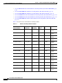
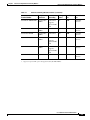
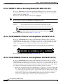
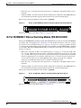
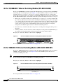
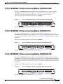
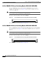
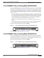
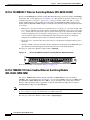
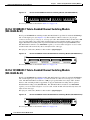
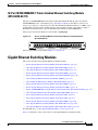
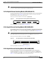
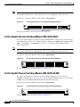
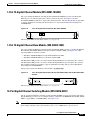
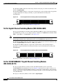
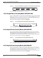
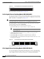
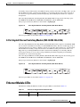
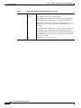
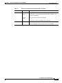
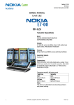
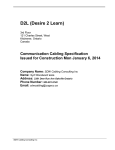
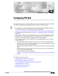
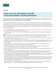
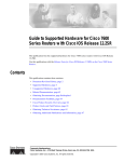
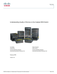
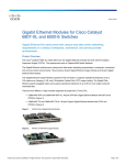
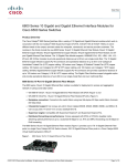
C H A P T E R
2
Ethernet and Gigabit Ethernet Switching
Modules
This chapter describes the Ethernet and Gigabit Ethernet switching modules, and it contains these
sections:
•
10/100 and 10/100/1000 Ethernet Switching Modules, page 2-1
•
Gigabit Ethernet Switching Modules, page 2-13
•
Ethernet Module LEDs, page 2-21
10/100 and 10/100/1000 Ethernet Switching Modules
Note
Specific combinations of supervisor engines and modules may not be supported in your chassis. Refer
to the release notes for the software version running on your system for specific information on modules
and supervisor engine combinations that are not supported.
This section describes these 10/100 and 10/100/1000 Ethernet switching modules:
•
24-Port 10BASE-FL Ethernet Switching Module (WS-X6024-10FL-MT), page 2-4
•
48-Port 10/100/1000BASE-T Ethernet Switching Module (WS-X6148-GE-TX), page 2-4
•
48-Port 10/100/1000BASE-T Ethernet Switching Module (WS-X6148V-GE-TX), page 2-4
•
48-Port 10/100BASE-T Ethernet Switching Module (WS-X6148-RJ21V), page 2-5
•
48-Port 10/100BASE-T Ethernet Switching Module (WS-X6148-RJ45V), page 2-6
•
24-Port 100BASE-FX Ethernet Switching Module (WS-X6224-100FX-MT), page 2-6
•
48-Port 10/100BASE-T Ethernet Switching Module (WS-X6248-RJ45), page 2-7
•
48-Port 10/100BASE-T Ethernet Switching Module (WS-X6248-TEL), page 2-7
•
48-Port 10/100BASE-T Ethernet Switching Module (WS-X6248A-TEL), page 2-7
•
24-Port 100BASE-FX Ethernet Switching Module (WS-X6324-100FX-MM), page 2-8
•
24-Port 100BASE-FX Ethernet Switching Module (WS-X6324-100FX-SM), page 2-8
•
48-Port 10/100BASE-T Ethernet Switching Module (WS-X6348-RJ21V), page 2-9
•
48-Port 10/100BASE-T Ethernet Switching Module (WS-X6348-RJ-45), page 2-9
•
48-Port 10/100BASE-T Ethernet Switching Module (WS-X6348-RJ45V), page 2-10
Cisco 7600 Series Routers Module Guide
OL-9392-04
2-1
Chapter 2
Ethernet and Gigabit Ethernet Switching Modules
10/100 and 10/100/1000 Ethernet Switching Modules
•
24-Port 100BASE-FX Fabric-Enabled Ethernet Switching Module (WS-X6524-100FX-MM), page
2-10
•
48-Port 10/100/1000BASE-T Ethernet Switching Module (WS-X6548-GE-TX), page 2-11
•
48-Port 10/100/1000BASE-T Ethernet Switching Module (WS-X6548V-GE-TX), page 2-11
•
48-Port 10/100BASE-T Fabric-Enabled Ethernet Switching Module (WS-X6548-RJ-21), page 2-12
•
48-Port 10/100BASE-T Fabric-Enabled Ethernet Switching Module (WS-X6548-RJ-45), page 2-12
•
48-Port 10/100/1000BASE-T Fabric-Enabled Ethernet Switching Module (WS-X6748-GE-TX),
page 2-13
Table 2-1 lists the features of the Ethernet switching modules.
Table 2-1
Ethernet Switching Modules Features
Product Number
Backplane
Connection
Forwarding
Inline
Power1
Port Buffer
Size
Queues Per
Port
WS-X6024-10FL-MT
32 Gbps Bus
Centralized
No
128 KB
2 transmit,
1 receive
WS-X6148-GE-TX
32 Gbps Bus
Centralized
Optional2
128 KB
2 transmit,
1 receive
WS-6148V-GE-TX
32 Gbps Bus
Centralized
Yes
128 KB
2 transmit,
1 receive
WS-X6148-RJ21V
32 Gbps Bus
Centralized
Yes
128 KB
2 transmit,
1 receive
WS-X6148-RJ45V
32 Gbps Bus
Centralized
Yes
128 KB
2 transmit,
1 receive
WS-X6224-100FX-MT
32 Gbps Bus
Centralized
Yes
128 KB
2 transmit,
1 receive
WS-X6248-RJ-45
32 Gbps Bus
Centralized
No
128 KB
2 transmit,
1 receive
WS-X6248-TEL
32 Gbps Bus
Centralized
No
128 KB
2 transmit,
1 receive
WS-X6248A-TEL
32 Gbps Bus
Centralized
No
128 KB
2 transmit,
1 receive
WS-X6324-100FX-MM
32 Gbps Bus
Centralized
No
128 KB
2 transmit,
1 receive
WS-X6324-100FX-SM
32 Gbps Bus
Centralized
No
128 KB
2 transmit,
1 receive
WS-X6348-RJ21V
32 Gbps Bus
Centralized
Yes
128 KB
2 transmit,
1 receive
WS-X6348-RJ-45
32 Gbps Bus
Centralized
Optional2
128 KB
2 transmit,
1 receive
WS-X6348-RJ45V
32 Gbps Bus
Centralized
Yes
128 KB
2 transmit,
1 receive
Cisco 7600 Series Routers Module Guide
2-2
OL-9392-04
Chapter 2
Ethernet and Gigabit Ethernet Switching Modules
10/100 and 10/100/1000 Ethernet Switching Modules
Table 2-1
Ethernet Switching Modules Features (continued)
Forwarding
Inline
Power1
Port Buffer
Size
Queues Per
Port
Switch Fabric
and Bus
Centralized
No
1 MB
4 transmit,
2 receive
WS-X6548-GE-TX
Switch Fabric
and Bus
Centralized
Optional2
1 MB
4 transmit,
2 receive
WS-6548V-GE-TX
Switch Fabric
and Bus
Centralized
Yes
1 MB
4 transmit,
2 receive
WS-X6548-RJ-21
Switch Fabric
and Bus
Centralized
No
1 MB
4 transmit,
2 receive
Switch Fabric
and Bus
Centralized
No
1 MB
4 transmit,
2 receive
Switch Fabric
CEF720
No
1.3 MB
4 transmit,
2 receive
Product Number
WS-X6524-100FX-MM
WS-X6548-RJ-45
WS-X6748-GE-TX
Backplane
Connection
Supports
optional DFC
card
Supports
optional DFC
card
Supports
optional DFC
card
1. Supports IP phones.
2. Supports an optional inline power field upgrade module (WS-F6K-VPWR=)
Cisco 7600 Series Routers Module Guide
OL-9392-04
2-3
Chapter 2
Ethernet and Gigabit Ethernet Switching Modules
10/100 and 10/100/1000 Ethernet Switching Modules
24-Port 10BASE-FL Ethernet Switching Module (WS-X6024-10FL-MT)
The 24-port 10BASE-FL switching module (WS-X6024-10FL-MT) provides 24 switched, 10-Mbps,
full- or half-duplex ports. (See Figure 2-1.) The module has 24 MT-RJ connectors for connection to
multimode fiber-optic (MMF) cable.
The QoS port architecture (Rx/Tx) for this module is 1q4t/2q2t.
Note
This module is a Class 1 laser product. Refer to the Regulatory Compliance and Safety Information for
the Cisco 7600 Series Routers for information on working with lasers.
Figure 2-1
24-Port 10BASE-FL Ethernet Switching Module (WS-X6024-10FL-MT)
26947
LIN
K
LIN
K
LIN
K
LIN
K
LIN
K
LIN
K
LIN
K
LIN
K
LIN
K
LIN
K
LIN
K
LIN
K
LIN
K
LIN
K
LIN
K
LIN
K
LIN
K
LIN
K
LIN
K
LIN
K
LIN
K
LIN
K
LIN
K
24 PORT 10FL
LIN
K
ST
AT
US
WS-X6024-10FL-MT
The front panel LEDs are described in Table 2-3 on page 2-21.
48-Port 10/100/1000BASE-T Ethernet Switching Module (WS-X6148-GE-TX)
The 48-port 10/100/1000BASE-T switching module (WS-X6148-GE-TX) provides 48 switched,
10/100/1000-Mbps autosensing, full- or half-duplex ports. (See Figure 2-2.) The module has 48 RJ-45
connectors for use with either Category 3, Category 5, Category 5e, or Category 6 UTP cable. This
module can be upgraded with an inline-power daughter card to support IP phones.
48-Port 10/100/1000BASE-T Ethernet Switching Module (WS-X6148-GE-TX)
47
48
48
47
46
45
44
43
42
41
40
39
38
37
36
35
34
33
32
31
PHONE
90851
37
38
SWITCHING MODULE
30
10/100/1000
BASE-T GE
35
36
29
24
23
22
21
20
19
18
17
16
15
14
12
11
9
8
10
7
6
5
4
3
2
1
48 PORT
25
26
28
23
24
27
STATUS
13
14
26
11
12
2
25
WS-X6148V-GE-TX 1
13
Figure 2-2
The front panel LEDs are described in Table 2-3 on page 2-21.
48-Port 10/100/1000BASE-T Ethernet Switching Module (WS-X6148V-GE-TX)
The 48-port 10/100/1000BASE-T switching module (WS-X6148V-GE-TX) provides 48 switched,
10/100/1000-Mbps autosensing, full- or half-duplex ports. (See Figure 2-3.) The module has 48 RJ-45
connectors for use with either Category 3, Category 5, Category 5e, or Category 6 UTP cable. The “V”
in the product number indicates that the inline-power daughter card is installed on the module. With the
voice daughter card installed, the module provides these IP phone features on each port:
•
Inline power—Provides 48 VDC over standard Category 5, Category 5e, or Category 6 UTP cable
up to 328 feet (100 meters) from the switch to the IP phone. With inline power, pairs 2 and 3 (pins
1, 2, 3, and 6) of the four pairs in the cable are used to transmit power (6.3 W) from the switch. This
method of supplying power is sometimes called phantom power because the power signals travel
over the same two pairs used to transmit Ethernet signals. The power signals are completely
transparent to the Ethernet signals and do not interfere with their operation.
Cisco 7600 Series Routers Module Guide
2-4
OL-9392-04
Chapter 2
Ethernet and Gigabit Ethernet Switching Modules
10/100 and 10/100/1000 Ethernet Switching Modules
•
Phone discovery—Automatically detects the presence of an IP phone and supplies inline power to
the phone.
•
Auxiliary VLANs—Provides automatic VLAN configuration for IP phones using IEEE 802.1Q as
the standards-based VLAN tagging mechanism between the switch and the IP phone.
The QoS port architecture (Rx/Tx) for this module is 1q4t/2q2t.
48-Port 10/100/1000BASE-T Ethernet Switching Module (WS-X6148V-GE-TX)
47
48
48
47
46
45
44
43
42
41
40
39
38
37
36
35
34
33
32
PHONE
90851
37
38
SWITCHING MODULE
31
10/100/1000
BASE-T GE
35
36
30
24
23
22
21
20
19
18
17
16
15
14
13
12
9
11
8
10
7
6
5
4
3
2
1
48 PORT
25
26
29
23
24
28
STATUS
13
14
27
11
12
2
26
WS-X6148V-GE-TX 1
25
Figure 2-3
The front panel LEDs are described in Table 2-3 on page 2-21.
48-Port 10/100BASE-T Ethernet Switching Module (WS-X6148-RJ21V)
The 48-port 10/100BASE-T switching module (WS-X6148-RJ21V) provides 48 switched, 10/100-Mbps
autosensing, full- or half-duplex ports. (See Figure 2-4.) The module has 4 RJ-21 connectors (12 ports
per connector) for use with either Category 3, Category 5, Category 5e, or Category 6 UTP cable. The
“V” in the product number indicates that the inline-power daughter card (WS-F6K-VPWR) is installed
on the module. With the WS-F6K-VPWR daughter card installed, the module provides these IP phone
features on each port:
•
Inline power—Provides 48 VDC over standard Category 5, Category 5e, or Category 6 UTP cable
up to 328 feet (100 meters) from the switch to the IP phone. With inline power, pairs 2 and 3 (pins
1, 2, 3, and 6) of the four pairs in the cable are used to transmit power (6.3 W) from the switch. This
method of supplying power is sometimes called phantom power because the power signals travel
over the same two pairs used to transmit Ethernet signals. The power signals are completely
transparent to the Ethernet signals and do not interfere with their operation.
•
Phone discovery—Automatically detects the presence of an IP phone and supplies inline power to
the phone.
•
Auxiliary VLANs—Provides automatic VLAN configuration for IP phones using IEEE 802.1Q as
the standards-based VLAN tagging mechanism between the switch and the IP phone.
The QoS port architecture (Rx/Tx) for this module is 1q4t/2q2t.
Figure 2-4
48-Port 10/100BASE-T Ethernet Switching Module (WS-X6148-RJ21V)
8
37
48 PORT
10/100 BASE-T
ETHERNET
SWITCHING MODULE
48
47
46
45
44
43
42
41
40
39
38
PHONE
37
36
35
34
33
32
31
30
29
28
27
26
25
24
23
22
21
20
19
18
17
16
15
14
13
12
11
10
9
8
7
6
5
4
3
2
1
STATUS
68149
-4
6
25
-3
-2
13
1-
12
4
WS-X6348-RJ21
The front panel LEDs are described in Table 2-3 on page 2-21.
Cisco 7600 Series Routers Module Guide
OL-9392-04
2-5
Chapter 2
Ethernet and Gigabit Ethernet Switching Modules
10/100 and 10/100/1000 Ethernet Switching Modules
48-Port 10/100BASE-T Ethernet Switching Module (WS-X6148-RJ45V)
The 48-port 10/100BASE-T switching module (WS-X6148-RJ45V) provides 48 switched, 10/100-Mbps
autosensing, full- or half-duplex ports. (See Figure 2-5.) The module has 48 RJ-45 connectors for use
with either Category 3, Category 5, Category 5e, or Category 6 UTP cable. The “V” in the product
number indicates that the inline-power daughter card (WS-F6K-VPWR) is installed on the module. With
the WS-F6K-VPWR daughter card installed, the module provides these IP phone features on each port:
•
Inline power—Provides 48 VDC over standard Category 5, Category 5e, or Category 6 UTP cable
up to 328 feet (100 meters) from the switch to the IP phone. With inline power, pairs 2 and 3 (pins
1, 2, 3, and 6) of the four pairs in the cable are used to transmit power (6.3 W) from the switch. This
method of supplying power is sometimes called phantom power because the power signals travel
over the same two pairs used to transmit Ethernet signals. The power signals are completely
transparent to the Ethernet signals and do not interfere with their operation.
•
Phone discovery—Automatically detects the presence of an IP phone and supplies inline power to
the phone.
•
Auxiliary VLANs—Provides automatic VLAN configuration for IP phones using IEEE 802.1Q as
the standards-based VLAN tagging mechanism between the switch and the IP phone.
The QoS port architecture (Rx/Tx) for this module is 1q4t/2q2t.
Figure 2-5
48-Port 10/100BASE-T Ethernet Switching Module (WS-X6148-RJ45V)
39334
47
48
47
46
45
48
44
43
42
41
40
39
38
37
36
35
34
33
32
31
30
29
28
27
26
PHONE
25
ETHERNET SWITCHING
MODULE
37
38
35
36
25
26
23
24
24
23
22
21
20
19
18
17
16
15
14
13
9
48 PORT
10/100 BASE-T
12
8
11
7
10
6
5
4
3
2
1
STATUS
13
14
2
1
11
12
WS-X6348-RJ-45V
The front panel LEDs are described in Table 2-3 on page 2-21.
24-Port 100BASE-FX Ethernet Switching Module (WS-X6224-100FX-MT)
The 24-port 100BASE-FX Etherent switching module (WS-X6224-100FX-MT) provides 24 switched,
100-Mbps, full or half-duplex ports. (See Figure 2-6.) Ports have MT-RJ optical connectors for
connection to MMF optical cable.
Note
This module is a Class 1 laser product. Refer to the Regulatory Compliance and Safety Information for
the Cisco 7600 Series Routers for information on working with lasers.
The QoS port architecture (Rx/Tx) for this module is 1q4t/2q2t.
Figure 2-6
24-Port 100BASE-FX Ethernet Switching Module (WS-X6224-100FX-MT)
2
3
4
5
6
7
8
9
10
11
12
13
14
15
16
17
18
19
20
21
22
23
24
K
N
LI
K
N
LI
K
N
LI
K
N
LI
K
K
N
N
LI
LI
K
N
LI
K
N
LI
K
N
LI
K
N
K
N
LI
LI
K
N
LI
K
N
LI
K
N
LI
K
N
LI
K
N
LI
K
K
K
K
N
N
LI
LI
N
LI
N
LI
K
N
LI
K
K
N
N
LI
LI
K
N
LI
24 PORT 100FX
16063
1
ST
AT
US
WS-X6224
100BASE-FX ports
The front panel LEDs are described in Table 2-3 on page 2-21.
Cisco 7600 Series Routers Module Guide
2-6
OL-9392-04
Chapter 2
Ethernet and Gigabit Ethernet Switching Modules
10/100 and 10/100/1000 Ethernet Switching Modules
48-Port 10/100BASE-T Ethernet Switching Module (WS-X6248-RJ45)
The 48-port 10/100BASE-T Ethernet switching module (WS-X6248-RJ45) provides 48 switched
10/100-Mbps autosensing, full or half-duplex ports. (See Figure 2-7.) The 48 ports have RJ-45
connectors for Category 3, Category 5, Category 5e, or Category 6 UTP or FTP cable.
The QoS port architecture (Rx/Tx) for this module is 1q4t/2q2t.
Figure 2-7
48-Port 10/100BASE-TX Ethernet Switching Module (WS-X6248-RJ45)
16791
48
47
46
45
44
43
42
41
40
39
38
37
48
38
36
35
34
33
32
31
30
29
28
27
36
26
26
ETHERNET SWITCHING
MODULE
25
24
23
22
21
20
19
18
17
16
15
14
24
14
48 PORT
10/100 BASE-T
13
9
12
8
11
7
10
6
5
4
3
2
1
2
12
1
WS-X6248-RJ-45
The front panel LEDs are described in Table 2-3 on page 2-21.
48-Port 10/100BASE-T Ethernet Switching Module (WS-X6248-TEL)
The 48-port 10/100BASE-T Ethernet switching module (WS-X6248-TEL) provides 48 switched
10/100-Mbps autosensing, full or half-duplex ports. (See Figure 2-8.) Four RJ-21 connectors (12 ports
per connector) use Category 3, Category 5, Category 5e, or Category 6 UTP or FTP cable to connect to
the network.
The QoS port architecture (Rx/Tx) for this module is 1q4t/2q2t.
Figure 2-8
48-Port 10/100BASE-T Ethernet Switching Module (WS-X6248-TEL)
8
6
18502
48
47
46
45
44
43
42
41
40
39
38
37
36
35
34
33
32
31
30
29
28
27
26
25
37
-4
-3
25
24
23
22
21
20
19
18
17
16
15
ETHERNET SWITCHING
MODULE
14
48 PORT
10/100 BASE-T
13
13
12
11
10
9
8
7
6
5
4
3
2
1
1-
12
-2
4
WS-X6248-RJ-TEL
The front panel LEDs are described in Table 2-3 on page 2-21.
48-Port 10/100BASE-T Ethernet Switching Module (WS-X6248A-TEL)
The 48-port 10/100BASE-T Ethernet switching module (WS-X6248A-TEL) provides 48 switched
10/100-Mbps autosensing, full or half-duplex ports. (See Figure 2-9.) The WS-X6248A-TEL Ethernet
module has a larger buffer than the WS-X6248-TEL Ethernet module. Four RJ-21 connectors (12 ports
per connector) use Category 3, Category 5, Category 5e, or Category 6 UTP or FTP cable to connect to
the network.
The QoS port architecture (Rx/Tx) for this module is 1q4t/2q2t.
Figure 2-9
48-Port 10/100BASE-T Ethernet Switching Module (WS-X6248A-TEL)
8
6
18502
48
47
46
45
44
43
42
41
40
39
38
37
36
35
34
33
32
31
30
29
28
27
26
25
37
-4
-3
25
24
23
22
21
20
19
18
17
16
15
ETHERNET SWITCHING
MODULE
14
48 PORT
10/100 BASE-T
13
13
12
11
10
9
8
7
6
5
4
3
2
1
1-
12
-2
4
WS-X6248-RJ-TEL
The front panel LEDs are described in Table 2-3 on page 2-21.
Cisco 7600 Series Routers Module Guide
OL-9392-04
2-7
Chapter 2
Ethernet and Gigabit Ethernet Switching Modules
10/100 and 10/100/1000 Ethernet Switching Modules
24-Port 100BASE-FX Ethernet Switching Module (WS-X6324-100FX-MM)
The 24-port 100BASE-FX switching module (WS-X6324-100FX-MM) provides 24 switched,
100-Mbps, full- or half-duplex ports. (See Figure 2-10.) The module has 24 MT-RJ connectors for
connection to the MMF cable.
Note
This module is a Class 1 laser product. Refer to the Regulatory Compliance and Safety Information for
the Cisco 7600 Series Routers for information on working with lasers.
The QoS port architecture (Rx/Tx) for this module is 1q4t/2q2t.
Figure 2-10
24-Port 100BASE-FX Ethernet Switching Module (WS-X6324-100FX-MM)
2
3
4
5
6
7
8
9
10
11
12
13
14
15
16
17
18
19
20
21
22
23
24
K
K
N
LI
K
N
LI
K
N
LI
K
N
LI
K
N
LI
K
N
LI
K
N
LI
K
N
LI
K
N
LI
K
N
LI
K
N
LI
K
N
LI
K
N
LI
K
N
LI
K
N
LI
K
N
LI
K
N
LI
K
N
LI
K
N
LI
K
N
LI
K
N
LI
K
N
N
LI
LI
LI
N
K
24 PORT 100FX-MMF
44744
1
ST
AT
US
WS-X6324-100FX-MM
The front panel LEDs are described in Table 2-3 on page 2-21.
24-Port 100BASE-FX Ethernet Switching Module (WS-X6324-100FX-SM)
The 24-port 100BASE-FX switching module (WS-X6324-100FX-SM) provides 24 switched, 100-Mbps,
full- or half-duplex ports. (See Figure 2-11.) The module has 24 MT-RJ connectors for connection to
SMF cable.
Note
This module is a Class 1 laser product. Refer to the Regulatory Compliance and Safety Information for
the Cisco 7600 Series Routers for information on working with lasers.
The QoS port architecture (Rx/Tx) for this module is 1q4t/2q2t.
Figure 2-11
24-Port 100BASE-FX Ethernet Switching Module (WS-X6324-100FX-SM)
2
3
4
5
6
7
8
9
10
11
12
13
14
15
16
17
18
19
20
21
22
23
24
K
N
LI
K
N
LI
K
N
LI
K
N
LI
K
N
LI
K
K
N
LI
K
N
LI
N
LI
K
N
LI
K
N
LI
K
N
LI
K
K
N
LI
K
N
LI
N
LI
K
N
LI
K
N
LI
K
N
LI
K
N
LI
K
K
N
LI
K
N
LI
N
LI
K
LI
N
K
N
LI
K
N
LI
24 PORT 100FX-SMF
44745
1
ST
AT
US
WS-X6324-100FX-SM
The front panel LEDs are described in Table 2-3 on page 2-21.
Cisco 7600 Series Routers Module Guide
2-8
OL-9392-04
Chapter 2
Ethernet and Gigabit Ethernet Switching Modules
10/100 and 10/100/1000 Ethernet Switching Modules
48-Port 10/100BASE-T Ethernet Switching Module (WS-X6348-RJ21V)
The 48-port 10/100BASE-T switching module (WS-X6148-RJ21V) provides 48 switched, 10/100-Mbps
autosensing, full- or half-duplex ports. (See Figure 2-12.) The module has 4 RJ-21 connectors (12 ports
per connector) for use with either Category 3, Category 5, Category 5e, or Category 6 UTP cable. The
“V” in the product number indicates that the inline-power daughter card (WS-F6K-VPWR) is installed
on the module. With the WS-F6K-VPWR daughter card installed, the module provides these IP phone
features on each port:
•
Inline power—Provides 48 VDC over standard Category 5, Category 5e, or Category 6 UTP cable
up to 328 feet (100 meters) from the switch to the IP phone. With inline power, pairs 2 and 3 (pins
1, 2, 3, and 6) of the four pairs in the cable are used to transmit power (6.3 W) from the switch. This
method of supplying power is sometimes called phantom power because the power signals travel
over the same two pairs used to transmit Ethernet signals. The power signals are completely
transparent to the Ethernet signals and do not interfere with their operation.
•
Phone discovery—Automatically detects the presence of an IP phone and supplies inline power to
the phone.
•
Auxiliary VLANs—Provides automatic VLAN configuration for IP phones using IEEE 802.1Q as
the standards-based VLAN tagging mechanism between the switch and the IP phone.
The QoS port architecture (Rx/Tx) for this module is 1q4t/2q2t.
Figure 2-12
48-Port 10/100BASE-T Ethernet Switching Module (WS-X6348-RJ-21V)
8
37
10/100 BASE-T
ETHERNET
SWITCHING MODULE
48
47
46
45
44
43
42
41
40
39
38
PHONE
37
36
35
34
33
32
31
30
29
28
27
26
25
24
23
22
21
20
19
18
17
16
15
14
13
9
12
8
11
7
10
6
5
4
3
2
1
STATUS
68149
-4
6
25
-3
-2
48 PORT
1-
13
12
4
WS-X6348-RJ21
The front panel LEDs are described in Table 2-3 on page 2-21.
48-Port 10/100BASE-T Ethernet Switching Module (WS-X6348-RJ-45)
The 48-port 10/100BASE-T switching module (WS-X6348-RJ-45) provides 48 switched, 10/100-Mbps
autosensing, full- or half-duplex ports. (See Figure 2-13.) The module has 48 RJ-45 connectors for
connection to either Category 3, Category 5, Category 5e, or Category 6 UTP or FTP cable. This module
can be upgraded with an inline-power daughter card to support IP phones.
The QoS port architecture (Rx/Tx) for this module is 1q4t/2q2t.
Figure 2-13
48-Port 10/100BASE-T Ethernet Switching Module (WS-X6348-RJ-45)
48
47
46
45
44
43
42
41
40
39
38
37
36
35
34
33
32
31
30
29
28
27
PHONE
26
ETHERNET SWITCHING
MODULE
25
24
23
22
21
20
19
18
17
16
15
14
48 PORT
10/100 BASE-T
13
12
11
10
9
8
7
6
5
4
3
2
1
STATUS
39496
48
38
36
26
24
12
2
14
1
WS-X6348-RJ-45
The front panel LEDs are described in Table 2-3 on page 2-21.
Cisco 7600 Series Routers Module Guide
OL-9392-04
2-9
Chapter 2
Ethernet and Gigabit Ethernet Switching Modules
10/100 and 10/100/1000 Ethernet Switching Modules
48-Port 10/100BASE-T Ethernet Switching Module (WS-X6348-RJ45V)
The 48-port 10/100BASE-T switching module (WS-X6348-RJ45V) provides 48 switched, 10/100-Mbps
autosensing, full- or half-duplex ports. (See Figure 2-14.) The module has 48 RJ-45 connectors for use
with either Category 3, Category 5, Category 5e, or Category 6 UTP or FTP cable. The “V” in the
product number indicates that the inline-power daughter card (WS-F6K-VPWR) is installed on the
module. With the WS-F6K-VPWR daughter card installed, the module provides these IP phone features
on each port:
•
Inline power—Provides 48 VDC over standard Category 5, Category 5e, or Category 6 UTP cable
up to 328 feet (100 meters) from the switch to the IP phone. With inline power, pairs 2 and 3 (pins
1, 2, 3, and 6) of the four pairs in the cable are used to transmit power (6.3 W) from the switch. This
method of supplying power is sometimes called phantom power because the power signals travel
over the same two pairs used to transmit Ethernet signals. The power signals are completely
transparent to the Ethernet signals and do not interfere with their operation.
•
Phone discovery—Automatically detects the presence of an IP phone and supplies inline power to
the phone.
•
Auxiliary VLANs—Provides automatic VLAN configuration for IP phones using IEEE 802.1Q as
the standards-based VLAN tagging mechanism between the switch and the IP phone.
The QoS port architecture (Rx/Tx) for this module is 1q4t/2q2t.
Figure 2-14
48-Port 10/100BASE-T Ethernet Switching Module (WS-X6348-RJ45V)
48
47
46
45
44
43
42
41
40
39
38
37
36
35
34
33
32
31
30
29
28
27
26
PHONE
39334
47
48
37
38
35
36
25
26
ETHERNET SWITCHING
MODULE
25
23
24
24
23
22
21
20
19
18
17
16
15
14
48 PORT
10/100 BASE-T
13
9
12
8
11
7
10
6
5
4
3
2
1
STATUS
13
14
2
1
11
12
WS-X6348-RJ-45V
The front panel LEDs are described in Table 2-3 on page 2-21.
24-Port 100BASE-FX Fabric-Enabled Ethernet Switching Module
(WS-X6524-100FX-MM)
The 24-port 100BASE-FX switching module (WS-X6524-100FX-MM) provides 24 switched,
100-Mbps, full- or half-duplex ports. (See Figure 2-15.) Ports have MT-RJ connectors for MMF cable.
The WS-X6524-100FX-MM module has 1-MB per-port packet buffers and a single fabric channel
interface. The switching module is upgradable to support distributed forwarding with an optional
Distributed Forwarding Card (WS-F6K-DFC).
Note
This module is a Class 1 laser product. Refer to the Regulatory Compliance and Safety Information for
the Cisco 7600 Series Routers for information on working with lasers.
The QoS port architecture (Rx/Tx) for this module is 1p1q0t/1p3q1t.
Cisco 7600 Series Routers Module Guide
2-10
OL-9392-04
Chapter 2
Ethernet and Gigabit Ethernet Switching Modules
10/100 and 10/100/1000 Ethernet Switching Modules
Figure 2-15
24-Port 100BASE-FX Fabric-Enabled Ethernet Switching Module
(WS-X6524-100FX-MM)
WS-X6524-100FX-MM
24 PORT 100FX-MMF
63671
N
K
LI
N
K
24
LI
N
K
23
LI
N
K
22
LI
N
K
21
LI
N
K
20
LI
N
K
19
LI
N
K
18
LI
N
K
17
LI
N
K
16
LI
N
K
15
LI
N
K
14
LI
N
K
13
LI
N
K
12
LI
N
K
11
LI
N
K
10
LI
N
K
9
LI
N
K
8
LI
N
K
7
LI
N
K
6
LI
N
K
5
LI
LI
LI
LI
4
N
K
3
N
K
2
N
K
1
STATUS
The front panel LEDs are described in Table 2-3 on page 2-21.
48-Port 10/100/1000BASE-T Ethernet Switching Module (WS-X6548-GE-TX)
The 48-port 10/100/1000BASE-T switching module (WS-X6548-GE-TX) provides 48 switched,
10/100/1000-Mbps autosensing, full- or half-duplex ports. (See Figure 2-16.) The module has 48 RJ-45
connectors for use with either Category 3, Category 5, Category 5e, or Category 6 UTP cable. This
module can be upgraded with an inline-power daughter card to support IP phones.
48-Port 10/100/1000BASE-T Ethernet Switching Module (WS_X6548-GE-TX)
47
48
48
47
46
45
44
43
42
41
40
39
38
37
36
35
34
33
32
30
PHONE
90852
37
38
SWITCHING MODULE
29
10/100/1000
BASE-T GE
35
36
31
24
23
22
21
20
19
18
17
16
15
12
11
10
9
8
7
6
5
4
3
2
1
48 PORT
25
26
28
23
24
27
STATUS
13
14
26
11
12
2
25
1
14
WS-X6148-GE-TX
13
Figure 2-16
The front panel LEDs are described in Table 2-3 on page 2-21.
48-Port 10/100/1000BASE-T Ethernet Switching Module (WS-X6548V-GE-TX)
The 48-port 10/100/1000BASE-T switching module (WS-X6548V-GE-TX) provides 48 switched,
10/100/1000-Mbps autosensing, full- or half-duplex ports. (See Figure 2-17.) The module has 48 RJ-45
connectors for use with either Category 3, Category 5, Category 5e, or Category 6 UTP cable. The “V”
in the product number indicates that the inline-power daughter card is installed on the module. With the
voice daughter card installed, the module provides these IP phone features on each port:
•
Inline power—Provides 48 VDC over standard Category 5, Category 5e, or Category 6 UTP cable
up to 328 feet (100 meters) from the switch to the IP phone. With inline power, pairs 2 and 3 (pins
1, 2, 3, and 6) of the four pairs in the cable are used to transmit power (6.3 W) from the switch. This
method of supplying power is sometimes called phantom power because the power signals travel
over the same two pairs used to transmit Ethernet signals. The power signals are completely
transparent to the Ethernet signals and do not interfere with their operation.
•
Phone discovery—Automatically detects the presence of an IP phone and supplies inline power to
the phone.
•
Auxiliary VLANs—Provides automatic VLAN configuration for IP phones using IEEE 802.1Q as
the standards-based VLAN tagging mechanism between the switch and the IP phone.
The QoS port architecture (Rx/Tx) for this module is 1q4t/2q2t.
Cisco 7600 Series Routers Module Guide
OL-9392-04
2-11
Chapter 2
Ethernet and Gigabit Ethernet Switching Modules
10/100 and 10/100/1000 Ethernet Switching Modules
48-Port 10/100/1000BASE-T Ethernet Switching Module (WS-X6548V-GE-TX)
37
38
47
48
48
47
46
45
44
43
42
41
40
39
38
PHONE
37
36
35
34
33
32
SWITCHING MODULE
31
10/100/1000
BASE-T GE
24
23
22
21
20
19
18
17
16
15
14
13
9
12
8
11
7
10
6
5
4
3
2
1
48 PORT
35
36
90852
25
26
30
23
24
29
STATUS
13
14
28
11
12
2
27
1
26
WS-X6148-GE-TX
25
Figure 2-17
The front panel LEDs are described in Table 2-3 on page 2-21.
48-Port 10/100BASE-T Fabric-Enabled Ethernet Switching Module
(WS-X6548-RJ-21)
The 48-port 10/100BASE-T switching module (WS-X6548-RJ-21) provides 48 switched, 10/100-Mbps,
full- or half-duplex ports. (See Figure 2-18.) The module has 4 RJ-21 connectors (12 ports per
connector) for Category 5, Category 5e, or Category 6 cable. The WS-X6548-RJ-21 module has 1-MB
per-port packet buffers and a single fabric channel interface. The switching module is upgradable to
support distributed forwarding with an optional Distributed Forwarding Card (WS-F6K-DFC). The
WS-X6548-RJ-21 module is auto-MDI/MDIX capable; you can use either straight or crossover cable,
and the module will automatically detect and adjust for the cable type.
The QoS port architecture (Rx/Tx) for this module is 1p1q0t/1p3q1t.
Figure 2-18
48-Port 10/100BASE-T Fabric-Enabled Ethernet Switching Module (WS-X6548-RJ-21)
8
48 PORT
10/100 BASE-T
ETHERNET
SWITCHING MODULE
63672
37
-4
6
25
-3
13
1-
-2
12
4
WS-X6548-RJ21
48
47
46
45
44
43
42
41
40
39
38
37
36
35
34
33
32
31
30
29
28
27
26
25
24
23
22
21
20
19
18
17
16
15
14
13
12
11
10
9
8
7
6
5
4
3
2
1
STATUS
The front panel LEDs are described in Table 2-3 on page 2-21.
48-Port 10/100BASE-T Fabric-Enabled Ethernet Switching Module
(WS-X6548-RJ-45)
The 48-port 10/100BASE-T switching module (WS-X6548-RJ-45) provides 48 switched, 10/100-Mbps,
full- or half-duplex ports. (See Figure 2-19.) Ports have RJ-45 connectors for Category 5, 5e, and 6
cable. The WS-X6548-RJ-45 module has 1-MB per-port packet buffers and a single fabric channel
interface. The switching module is upgradable to support distributed forwarding with an optional
Distributed Forwarding Card (WS-F6K-DFC). The WS-X6548-RJ-45 module is auto-MDI/MDIX
capable; you can use either straight or crossover cable, and the module will automatically detect and
adjust for the cable type.
The QoS port architecture (Rx/Tx) for this module is 1p1q0t/1p3q1t.
48-Port 10/100BASE-T Fabric-Enabled Ethernet Switching Module (WS-X6548-RJ-45)
47
46
45
44
43
42
41
40
39
38
37
36
35
34
33
32
31
63673
47
48
48
PH
O
N
E
37
38
SWITCHING MODULE
30
10/100 BASE-T
ETHERNET
35
36
29
24
23
22
21
20
19
18
17
16
15
12
11
10
9
8
7
6
5
4
3
2
1
48 PORT
25
26
28
23
24
27
STATUS
13
14
26
11
12
2
25
1
14
WS-X6548
13
Figure 2-19
The front panel LEDs are described in Table 2-3 on page 2-21.
Cisco 7600 Series Routers Module Guide
2-12
OL-9392-04
Chapter 2
Ethernet and Gigabit Ethernet Switching Modules
Gigabit Ethernet Switching Modules
48-Port 10/100/1000BASE-T Fabric-Enabled Ethernet Switching Module
(WS-X6748-GE-TX)
The 48-port 10/100/1000BASE-T switching module (WS-X6748-GE-TX) provides 48 switched,
10/100/1000-Mbps, full- or half-duplex ports. (See Figure 2-20.) Ports have RJ-45 connectors for
Category 5, Category 5e, and Category 6 cable. The WS-X6748-GE-TX module has 1.3-MB per-port
packet buffers and a dual-fabric channel interface. The switching module is upgradable to support
distributed forwarding with an optional Distributed Forwarding Card (WS-F6K-DFC3).
The QoS port architecture (Rx/Tx) for this module is 1q8t/1p3q8t.
Figure 2-20
48-Port 10/100/1000BASE-T Fabric-Enabled Ethernet Switching Module
(WS-X6748-GE-TX)
)
48 PORT 10/100/1000 RJ-45
11
12
2
13
14
23
24
25
26
35
36
37
38
47
48
99884
1
48
47
46
45
44
43
42
41
40
39
36
35
34
33
32
31
30
29
28
27
26
25
24
23
22
21
20
19
18
17
16
15
14
13
9
12
8
11
7
10
6
5
4
3
2
1
38
SWITCHING MODULE
STATUS
37
WS-X6748-GE-TX
The front panel LEDs are described in Table 2-3 on page 2-21.
Gigabit Ethernet Switching Modules
This section describes these Gigabit Ethernet switching modules:
•
16-Port Gigabit Ethernet Switching Module (WS-X6316-GE-TX), page 2-15
•
8-Port Gigabit Ethernet Switching Module (WS-X6408-GBIC), page 2-15
•
8-Port Gigabit Ethernet Switching Module (WS-X6408A-GBIC), page 2-15
•
16-Port Gigabit Ethernet Switching Module (WS-X6416-GBIC), page 2-16
•
16-Port Gigabit Ethernet Switching Module (WS-X6416-GE-MT), page 2-16
•
1-Port 10-Gigabit Ethernet Module (WS-X6501-10GEX4), page 2-17
•
1-Port 10-Gigabit Ethernet Base Module (WS-X6502-10GE), page 2-17
•
16-Port Gigabit Ethernet Switching Module (WS-X6516-GBIC), page 2-17
•
16-Port Gigabit Ethernet Switching Module (WS-X6516A-GBIC), page 2-18
•
16-Port 10/100/1000BASE-T Gigabit Ethernet Switching Module (WS-X6516-GE-TX), page 2-18
•
4-Port 10 Gigabit Ethernet Switching Module (WS-X6704-10GE), page 2-19
•
24-Port Gigabit Ethernet Switching Module (WS-X6724-SFP), page 2-19
•
48-Port Gigabit Ethernet Switching Module (WS-X6748-SFP), page 2-19
•
16-Port Gigabit Ethernet Switching Module (WS-X6816-GBIC), page 2-20
•
8-Port Gigabit Ethernet Switching Module (WS-X6708-10G-3C), page 2-20
•
8-Port Gigabit Ethernet Switching Module (WS-X6708-10G-3CXL), page 2-21
For LED indicators, see the “Ethernet Module LEDs” section on page 2-21.
Table 2-2 summarizes some of the features of the Gigabit Ethernet switching modules.
Cisco 7600 Series Routers Module Guide
OL-9392-04
2-13
Chapter 2
Ethernet and Gigabit Ethernet Switching Modules
Gigabit Ethernet Switching Modules
Table 2-2
Gigabit and 10-Gigabit Ethernet Switching Modules Features
Forwarding
Number of
Transmit
Queues/Port
Number of
Receive
Queues/Port
Bus
Centralized
3
2
WS-X6408-GBIC
Bus
Centralized
3
2
WS-X6408A-GBIC
Bus
Centralized
3
2
WS-X6416-GBIC
Bus
Centralized
3
2
WS-X6416-GE-MT
Bus
Centralized
3
2
WS-X6501-10GEX4
Switch fabric
and bus
Centralized. Support for 3
distributed forwarding
with optional
distributed forwarding
card (DFC)
2
WS-X6502 -10GE
Switch fabric
and bus
Centralized. Support for 3
distributed forwarding
with optional DFC
2
WS-X6516-GBIC
Switch fabric
and bus
Centralized. Support for 3
distributed forwarding
with optional DFC
2
WS-X6516A-GBIC
Switch fabric
and bus
Centralized. Support for 3
distributed forwarding
with optional DFC
2
WS-X6516-GE-TX
Switch fabric
and bus
Centralized. Support for 3
distributed forwarding
with optional DFC
2
WS-X6704-10GE
Switch fabric1 Centralized. Support for 3
(dual channel) distributed forwarding
with optional DFC
22
WS-X6724-SFP
Switch fabric
Centralized. Support for 3
distributed forwarding
with optional DFC
22
WS-X6748-SFP
Switch fabric
Centralized. Support for 3
distributed forwarding
with optional DFC
22
WS-X6816-GBIC
Switch fabric1 Distributed forwarding
(dual channel) with integrated DFC
3
2
WS-X6708-10G-3C
Switch fabric
Distributed forwarding
with integrated DFC
8
82
WS-X6708-10G-3CXL
Switch fabric
Distributed forwarding
with integrated DFC
8
82
Product Number
Backplane
Connection
WS-X6316-GE-TX
1. The module can be installed in slots 2–6 in the Cisco 7606, slots 2–9 in the Cisco 7609 and OSR-7609, and slots 9–13 in the Cisco
7613 routers. It cannot be installed in slots 2–8 of the Cisco 7613 router. The module requires a Supervisor Engine 720.
2. Receive queues change depending on whether you have a centralized forward card (CFC) or a DFC. For information about queue
structures, see http://www.cisco.com/en/US/docs/routers/7600/ios/12.2SXF/configuration/guide/qos.html#wp1666010.
Cisco 7600 Series Routers Module Guide
2-14
OL-9392-04
Chapter 2
Ethernet and Gigabit Ethernet Switching Modules
Gigabit Ethernet Switching Modules
Note
These modules are Class 1 laser products. Refer to the Regulatory Compliance and Safety Information
for the Cisco 7600 Series Routers for information on working with lasers.
16-Port Gigabit Ethernet Switching Module (WS-X6316-GE-TX)
The 16-port Gigabit Ethernet switching module (WS-X6316-GE-TX) provides 16 switched, full-duplex
Gigabit Ethernet ports. (See Figure 2-21.) Ports have RJ-45 connectors for Category 5 UTP. The
WS-X6316-GE-TX module has enhanced QoS features.
The QoS port architecture (Rx/Tx) for this module is 1p1q4t/1p2q2t.
Figure 2-21
16-Port Gigabit Ethernet Switching Module (WS-X6316-GE-TX)
2
3
LIN
K
4
5
6
7
8
9
10
11
12
13
14
15
16
44314
LIN
K
LIN
K
LIN
K
LIN
K
LIN
K
LIN
K
LIN
K
LIN
K
LIN
K
LIN
K
LIN
K
LIN
K
LIN
K
16 PORT 1000 BASE-T GE
LIN
K
ST
AT
1
LIN
K
US
WS-X6316-GE-7X
The front panel LEDs are described in Table 2-3 on page 2-21.
8-Port Gigabit Ethernet Switching Module (WS-X6408-GBIC)
The 8-port Gigabit Ethernet switching module (WS-X6408-GBIC) provides eight switched, full-duplex
Gigabit Ethernet ports that you can configure with any combination of 1000BASE-SX, LX/LH, and ZX
GBICs, copper GBICs, or Coarse Wave Division Multiplexer (CWDM) GBICs. (See Figure 2-22.)
Note
CWDM GBICs are used with the CWDM Passive Optical System. For more information on the CWDM
Passive Optical System, refer to the Installation Note for the CWDM Passive Optical System.
The QoS port architecture (Rx/Tx) for this module is 1q4t/2q2t.
Figure 2-22
8-Port Gigabit Ethernet Switching Module (WS-X6408-GBIC)
2
3
4
5
6
7
8
K
N
LI
K
N
LI
K
LI
N
K
N
LI
K
N
LI
K
N
LI
K
N
LI
LI
N
K
ST
8 PORT GIGABIT ETHERNET
16061
1
AT
US
WS-X6408
1000BASE-X GBIC ports
The front panel LEDs are described in Table 2-3 on page 2-21.
8-Port Gigabit Ethernet Switching Module (WS-X6408A-GBIC)
The 8-port Gigabit Ethernet switching module (WS-X6408A-GBIC) provides eight switched,
full-duplex Gigabit Ethernet ports that you can configure with any combination of 1000BASE-SX,
LX/LH, and ZX GBICs, copper GBICs, or Coarse Wave Division Multiplexer (CWDM) GBICs. (See
Figure 2-23.) The WS-X6408A-GBIC module has enhanced QoS features.
Cisco 7600 Series Routers Module Guide
OL-9392-04
2-15
Chapter 2
Ethernet and Gigabit Ethernet Switching Modules
Gigabit Ethernet Switching Modules
Note
CWDM GBICs are used with the CWDM Passive Optical System. For more information on the CWDM
Passive Optical System, refer to the Installation Note for the CWDM Passive Optical System.
The QoS port architecture (Rx/Tx) for this module is 1p1q4t/1p2q2t.
8-Port Gigabit Ethernet Switching Module (WS-X6408A-GBIC)
2
1
3
4
5
6
7
8
N
K
LI
N
K
LI
N
K
LI
N
K
LI
N
K
LI
N
K
LI
LI
LI
N
K
8 PORT GIGABIT ETHERNET
N
K
ST
16061
AT
US
Figure 2-23
X GBIC
The front panel LEDs are described in Table1000BASE
2-3 on page
2-21.
16-Port Gigabit Ethernet Switching Module (WS-X6416-GBIC)
The 16-port Gigabit Ethernet switching module (WS-X6416-GBIC) provides 16 switched, full-duplex
Gigabit Ethernet ports that you can configure with any combination of 1000BASE-SX, LX/LH, and ZX
GBICs, copper GBICs, or CWDM GBICs. (See Figure 2-24.) The WS-X6416-GBIC module has
enhanced QoS features.
Note
CWDM GBICs are used with the CWDM Passive Optical System. For more information on the CWDM
Passive Optical System, refer to the Installation Note for the CWDM Passive Optical System.
The QoS port architecture (Rx/Tx) for this module is 1p1q4t/1p2q2t.
Figure 2-24
16-Port Gigabit Ethernet Switching Module (WS-X6416-GBIC)
8
9
10
11
12
13
14
LIN
K
7
LIN
K
6
LIN
K
5
LIN
K
4
LIN
K
3
LIN
K
2
LIN
K
1
15
16
30694
16
16 PORT GIGABIT ETHERNET
LIN
K
15
14
LIN
K
13
12
LIN
K
11
10
LIN
K
9
8
LIN
K
7
6
LIN
K
5
4
LIN
K
3
2
LIN
K
1
LIN
K
ST
AT
US
WS-X6416-GBIC
The front panel LEDs are described in Table 2-3 on page 2-21.
16-Port Gigabit Ethernet Switching Module (WS-X6416-GE-MT)
The 16-port Gigabit Ethernet switching module (WS-X6416-GE-MT) provides 16 switched,
1000-Mbps, full-duplex ports. (See Figure 2-25.) The module has 16 MT-RJ connectors for connecting
to MMF cable. The WS-X6416-GE-MT module has enhanced QoS features.
The QoS port architecture (Rx/Tx) for this module is 1p1q4t/1p2q2t.
Figure 2-25
16-Port Gigabit Ethernet Switching Module (WS-X6416-GE-MT)
WS-X6416-GE-MT
2
3
4
5
6
7
8
9
10
11
12
13
14
15
16
K
LIN
K
LIN
K
LIN
K
LIN
K
26953
16 PORT GIGABIT ETHERNET
LIN
K
LIN
K
LIN
K
LIN
K
K
LIN
LIN
K
LIN
K
LIN
K
LIN
K
LIN
K
LIN
LIN
K
ST
AT
US
1
The front panel LEDs are described in Table 2-3 on page 2-21.
Cisco 7600 Series Routers Module Guide
2-16
OL-9392-04
Chapter 2
Ethernet and Gigabit Ethernet Switching Modules
Gigabit Ethernet Switching Modules
1-Port 10-Gigabit Ethernet Module (WS-X6501-10GEX4)
The 1-port 10-Gigabit Ethernet switching module (WS-X6501-10GEX4) provides one 10-Gigabit
Ethernet port accessible through an SC connector on the front panel. (See Figure 2-26.) The
WS-X6501-10GEX4 module has a single fabric channel interface. The switching module is upgradable
to support distributed forwarding with the installation of an optional Distributed Forwarding Card
(WS-F6K-DFC).
Figure 2-26
1-Port 10-Gigabit Ethernet Module (WS-X6501-10GEX4)
WS-X6501-10GEX4
RX
LIN
K
63675
ST
AT
US
TX
Metro 10GigE
10G BASE-EX4
The front panel LEDs are described in Table 2-3 on page 2-21.
1-Port 10-Gigabit Ethernet Base Module (WS-X6502-10GE)
The 1-port 10-Gigabit Ethernet switching module (WS-X6502-10GE) consists of a 10-Gigabit Ethernet
Base Module (WS-X6502-10GE) and an Optical Interface Module (OIM). (See Figure 2-27.) The
following OIMs are currently available:
•
WS-G6483 10GBASE-ER Serial 1550-nm Extended Reach OIM
•
WS-G6488 10GBASE-LR Serial 1310-nm Long Haul OIM
The WS-G6483 OIM provides one serial 1550-nm 10-Gigabit Ethernet port through an SC connector.
The WS-G6488 OIM provides one serial 1310-nm 10-Gigabit Ethernet port through an SC connector.
The switching module is upgradable to support distributed forwarding with an optional Distributed
Forwarding Card (WS-F6K-DFC).
The QoS port architecture (Rx/Tx) for this module is 1p1q8t/1p2q1t.
Figure 2-27
1-Port 10-Gigabit Ethernet Base Module (WS-X6502-10GE) with the WS-G6488 OIM
Installed
WS - G6488
TX
RX
10Gigabit Ethernet
10G BASE - LR Serial 1310nm Optical Interface Module
73779
LIN
K
ST
AT
US
WS-X6502 - 10GE
The front panel LEDs are described in Table 2-3 on page 2-21.
16-Port Gigabit Ethernet Switching Module (WS-X6516-GBIC)
The 16-port Gigabit Ethernet switching module (WS-X6516-GBIC) provides 16 switched, full-duplex
Gigabit Ethernet ports that you can configure with any combination of 1000BASE-SX, LX/LH, and ZX
GBICs, copper GBICs, or CWDM GBICs. (See Figure 2-28.)
Note
CWDM GBICs are used with the CWDM Passive Optical System. For more information on the CWDM
Passive Optical System, refer to the Installation Note for the CWDM Passive Optical System.
Cisco 7600 Series Routers Module Guide
OL-9392-04
2-17
Chapter 2
Ethernet and Gigabit Ethernet Switching Modules
Gigabit Ethernet Switching Modules
The WS-X6516-GBIC module has enhanced QoS features. The QoS port architecture (Rx/Tx) for this
module is 1p1q4t/1p2q2t.
The WS-X6516-GBIC module has a single fabric channel interface. The switching module is upgradable
to support distributed forwarding by installing an optional Distributed Forwarding Card
(WS-F6K-DFC).
Figure 2-28
16-Port Gigabit Ethernet Switching Module (WS-X6516-GBIC)
8
9
10
11
12
13
14
LIN
K
7
LIN
K
6
LIN
K
5
LIN
K
4
LIN
K
3
LIN
K
2
LIN
K
1
15
16
44315
16
16 PORT GIGABIT ETHERNET
LIN
K
15
14
LIN
K
13
12
LIN
K
11
10
LIN
K
9
8
LIN
K
7
6
LIN
K
5
4
LIN
K
3
2
LIN
K
1
LIN
K
ST
AT
US
WS-X6516-GBIC
The front panel LEDs are described in Table 2-3 on page 2-21.
16-Port Gigabit Ethernet Switching Module (WS-X6516A-GBIC)
The 16-port Gigabit Ethernet switching module (WS-X6516A-GBIC) provides 16 switched, full-duplex
Gigabit Ethernet ports that you can configure with any combination of 1000BASE-SX, LX/LH, and ZX
GBICs, copper GBICs, or CWDM GBICs. (See Figure 2-28.)
Note
CWDM GBICs are used with the CWDM Passive Optical System. For more information on the CWDM
Passive Optical System, refer to the Installation Note for the CWDM Passive Optical System.
The WS-X6516A-GBIC module has enhanced QoS features. The QoS port architecture (Rx/Tx) for this
module is 1p1q4t/1p2q2t. The module has 1 MB per port buffers.
The WS-X6516A-GBIC module has a single fabric channel interface. The switching module is
upgradable to support distributed forwarding by installing an optional Distributed Forwarding Card
(WS-F6K-DFC).
Figure 2-29
16-Port Gigabit Ethernet Switching Module (WS-X6516A-GBIC)
7
8
9
10
11
12
13
14
15
16
44315
6
LIN
K
5
LIN
K
4
LIN
K
3
LIN
K
2
LIN
K
1
LIN
K
16 PORT GIGABIT ETHERNET
LIN
K
16
LIN
K
15
14
LIN
K
13
12
LIN
K
11
10
LIN
K
9
8
LIN
K
7
6
LIN
K
5
4
LIN
K
3
2
LIN
K
1
LIN
K
ST
AT
US
WS-X6516-GBIC
The front panel LEDs are described in Table 2-3 on page 2-21.
16-Port 10/100/1000BASE-T Gigabit Ethernet Switching Module
(WS-X6516-GE-TX)
The 16-port Gigabit Ethernet switching module (WS-X6516-GE-TX) provides 16 switched,
10/100/1000BASE-T Gigabit Ethernet ports. (See Figure 2-30.) The ports have RJ-45 connectors for
Category 5 UTP. The WS-X6516-GE-TX module has a single fabric channel interface. The switching
module is upgradable to support distributed forwarding by installing an optional Distributed Forwarding
Card (WS-F6K-DFC).
The QoS port architecture (Rx/Tx) for this module is 1p1q4t/1p2q2t.
Cisco 7600 Series Routers Module Guide
2-18
OL-9392-04
Chapter 2
Ethernet and Gigabit Ethernet Switching Modules
Gigabit Ethernet Switching Modules
Figure 2-30
16-Port 10/100/1000BASE-T Gigabit Ethernet Switching Module (WS-X6516-GE-TX)
4
LIN
K
LIN
K
5
6
7
8
LIN
K
3
LIN
K
2
9
10
11
12
13
14
15
16
63187
LIN
K
LIN
K
LIN
K
LIN
K
LIN
K
LIN
K
LIN
K
LIN
K
LIN
K
LIN
K
16 PORT 1000 BASE-T GE
LIN
K
ST
AT
U
S
1
LIN
K
WS-X6516-GE-T X
The front panel LEDs are described in Table 2-3 on page 2-21.
4-Port 10 Gigabit Ethernet Switching Module (WS-X6704-10GE)
The 4-port 10-Gigabit Ethernet switching module (WS-X6704-10GE) provides 4 switched, 10-Gigabit
Ethernet ports. (See Figure 2-31.) The four ports support hot-swappable 10GBASE-LR long-reach or
10GBASE-ER extended reach XenPak optical transceivers. The WS-X6704-10GE module has dual
fabric channel interface and requires the Supervisor Engine 720.
The QoS port architecture (Rx/Tx) for this module is 1q8t/1p7q8t.
Figure 2-31
4-Port 10 Gigabit Ethernet Switching Module (WS-X6704-10GE)
WS-X6704-10GE
PORT 1
RX
TX
PORT 2
RX
TX
PORT 3
RX
TX
PORT 4
RX
4
K
2
3
LIN
1
K
K
K
LIN
LIN
LIN
99885
ST
AT
US
TX
4 PORT 10 GIGABIT ETHERNET
The front panel LEDs are described in Table 2-3 on page 2-21.
24-Port Gigabit Ethernet Switching Module (WS-X6724-SFP)
The 24-port Gigabit Ethernet switching module (WS-X6724-SFP) provides 24 switched, Gigabit
Ethernet ports. (See Figure 2-32.) The 24 ports support hot-swappable Small Form-Factor Pluggable
(SFP) 1000BASE-SX, 1000BASE-LX/LH, and 1000BASE-ZX optical transceivers. The
WS-X6724-SFP module has single fabric channel interface and requires the Supervisor Engine 720.
The QoS port architecture (Rx/Tx) for this module is 1q8t/1p3q8t.
24-Port Gigabit Ethernet Switching Module (WS-X6724-SFP)
WS-X6724-SFP
24 PORT GIGABIT ETHERNET-SFP
99886
Figure 2-32
STATUS
The front panel LEDs are described in Table 2-3 on page 2-21.
48-Port Gigabit Ethernet Switching Module (WS-X6748-SFP)
The 48-port Gigabit Ethernet switching module (WS-X6748-SFP) provides 48 switched, Gigabit
Ethernet ports. (See Figure 2-33.) The 48 ports support hot-swappable Small Form-Factor Pluggable
(SFP) 1000BASE-SX, 1000BASE-LX/LH, and 1000BASE-ZX optical transceivers. The
WS-X6748-SFP module has a dual fabric channel interface and requires the Supervisor Engine 720.
The QoS port architecture (Rx/Tx) for this module is 1q8t/1p3q8t.
Cisco 7600 Series Routers Module Guide
OL-9392-04
2-19
Chapter 2
Ethernet and Gigabit Ethernet Switching Modules
Gigabit Ethernet Switching Modules
Figure 2-33
48 PORT GIGABIT ETHERNET-SFP
144612
WS-X6748-SFP
48-Port Gigabit Ethernet Switching Module (WS-X6748-SFP)
STATUS
The front panel LEDs are described in Table 2-3 on page 2-21.
16-Port Gigabit Ethernet Switching Module (WS-X6816-GBIC)
The 16-Port Gigabit Ethernet switching module (WS-X6816-GBIC) provides 16 switched, full-duplex
Gigabit Ethernet ports that you can configure with any combination of 1000BASE-SX, LX/LH, and ZX
GBICs, copper GBICs, or CWDM GBICs. (See Figure 2-34.)
Note
CWDM GBICs are used with the CWDM Passive Optical System. For more information on the CWDM
Passive Optical System, refer to the Installation Note for the CWDM Passive Optical System.
The WS-X6816-GBIC is a fabric-dependent module that has enhanced QoS features. The QoS port
architecture (Rx/Tx) for this module is 1p1q4t/1p2q2t.
The WS-X6816-GBIC module has the following installation restrictions:
•
The WS-X6816-GBIC requires a Supervisor Engine 2 or Supervisor Engine 720.
The WS-X6816-GBIC must have a DFC3A daughter card installed to operate with the
Supervisor Engine 720.
Note
•
A Switch Fabric Module must be installed in the Cisco 7600 series routers chassis when a
WS-X6816-GBIC module is installed.
•
The WS-X6816-GBIC can be installed in slots 2 through 6 in the Cisco 7606 router.
•
The WS-X6816-GBIC can be installed in slots 2 through 9 in the Cisco 7609 router.
•
The WS-X6816-GBIC can only be installed in slots 9 through 13 in the Cisco 7613 router; it cannot
be installed in slots 2 through 8.
Figure 2-34
16-Port Gigabit Ethernet Switching Module (WS-X6816-GBIC)
1
2
3
4
5
6
7
8
9
10
11
12
13
14
15
16
52719
16
LIN
K
14
LIN
K
12
LIN
K
10
LIN
K
8
LIN
K
6
LIN
K
4
LIN
K
2
16 PORT GIGABIT ETHERNET
LIN
K
15
LIN
K
13
LIN
K
11
LIN
K
9
LIN
K
7
LIN
K
5
LIN
K
3
LIN
K
1
LIN
K
ST
AT
US
WS-X6816-GBIC
The front panel LEDs are described in Table 2-3 on page 2-21.
8-Port Gigabit Ethernet Switching Module (WS-X6708-10G-3C)
The 8-Port Gigabit Ethernet Switching Module (WS-X6708-10G-3C) comprises a WS-X6708-10GE
base board and a distributed forwarding card. The base module supports up to eight pluggable X2 optics
and has a 40 Gbps connection to the fabric and is therefore 2:1 oversubscribed. The distributed
Cisco 7600 Series Routers Module Guide
2-20
OL-9392-04
Chapter 2
Ethernet and Gigabit Ethernet Switching Modules
Ethernet Module LEDs
forwarding card provides hardware-based MAC learning and forwards traffic at 48 Mpps. The 8-port 10
Gigabit Ethernet module can demonstrate 60 Gbps local switching. Besides increased port density, it
also has increased port buffering and enhanced queuing and scheduling mechanisms for congestion
management.
The 8-Port Gigabit Ethernet Switching Module (WS-X6708-10G-3C) supports the following optics:
X2-10GB-SR, X2-10GB-LR, X2-10GB-ER, X2-10GB-LX4, and X2-10GB-CX4.
The QoS port architecture (Rx/Tx) for this module is 8q4t/1p7q4t.
8-Port Gigabit Ethernet Switching Module (WS-X6708-10G-3C)
241787
Figure 2-35
The front panel LEDs are described in Table 2-3 on page 2-21.
8-Port Gigabit Ethernet Switching Module (WS-X6708-10G-3CXL)
The 8-Port Gigabit Ethernet Switching Module (WS-X6708-10G-3CXL) comprises a WS-X6708-10GE
base board and a distributed forwarding card (WS-F6700-DFC3CXL). The base module supports up to
eight pluggable X2 optics and has a 40 Gbps connection to the fabric and is therefore 2:1 oversubscribed.
The distributed forwarding card provides hardware-based MAC learning and forwards traffic at 48
Mpps. The 8-port 10 Gigabit Ethernet module can demonstrate 60 Gbps local switching. Besides
increased port density, it also has increased port buffering and enhanced queuing and scheduling
mechanisms for congestion management. .
The 8-Port Gigabit Ethernet Switching Module (WS-X6708-10G-3CXL) supports the following optics:
X2-10GB-SR, X2-10GB-LR, X2-10GB-ER, X2-10GB-LX4, and X2-10GB-CX4.
The QoS port architecture (Rx/Tx) for this module is 8q4t/1p7q4t.
8-Port Gigabit Ethernet Switching Module (WS-X6708-10G-3C)
241787
Figure 2-36
The front panel LEDs are described in Table 2-3 on page 2-21.
Ethernet Module LEDs
The Ethernet and Gigabit Ethernet module front-panel LEDs are described in Table 2-3.
Table 2-3
Ethernet and Gigabit Ethernet Module LEDs
LED
Color/State
Description
STATUS
Green
All diagnostics pass; the module is operational.
Cisco 7600 Series Routers Module Guide
OL-9392-04
2-21
Chapter 2
Ethernet and Gigabit Ethernet Switching Modules
Ethernet Module LEDs
Table 2-3
LED
Ethernet and Gigabit Ethernet Module LEDs (continued)
Color/State
Description
Orange
The module is booting or running diagnostics.
An overtemperature condition has occurred. (A minor temperature
threshold has been exceeded during environmental monitoring.)
Red
The module is resetting. The switch has just been powered on or the
module has been hot inserted during the normal initialization
sequence.
An overtemperature condition has occurred. (A major temperature
threshold has been exceeded during environmental monitoring.)
If the module fails to download code and configuration information
successfully during the initial reset, the LED stays red; the module
does not come online.
Off
The module is not receiving power.
Cisco 7600 Series Routers Module Guide
2-22
OL-9392-04
Chapter 2
Ethernet and Gigabit Ethernet Switching Modules
Ethernet Module LEDs
Table 2-3
Ethernet and Gigabit Ethernet Module LEDs (continued)
LED
Color/State
Description
LINK
Green
The port is active (the link is connected and operational).
Orange
The module or port is disabled through the CLI command or the
module is initializing1.
Flashing
orange
The port is faulty and has been disabled.
Off
The port is not active or the link is not connected.
Green
The voice daughter card is installed.
Off
The voice daughter card is not detected or is not installed.
PHONE
1. This is a good time to verify that all LINK LEDs are functioning.
Cisco 7600 Series Routers Module Guide
OL-9392-04
2-23
Chapter 2
Ethernet and Gigabit Ethernet Switching Modules
Ethernet Module LEDs
Cisco 7600 Series Routers Module Guide
2-24
OL-9392-04