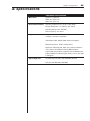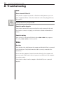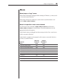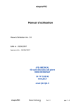
1
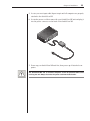
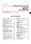
SwitchView MP
®
Installer/UserGuide
Guide
Installer/User
INSTRUCTIONS
The exclamation point within an equilateral triangle is intended to alert the
user to the presence of important operating and maintenance (servicing)
instructions in the literature accompanying the appliance.
DANGEROUS VOLTAGE
The lightning flash with arrowhead symbol, within an equilateral triangle, is
intended to alert the user to the presence of uninsulated “dangerous voltage”
within the product’s enclosure that may be of sufficient magnitude to constitute
a risk of electric shock to persons.
POWER ON
This symbol indicates the principle on/off switch is in the on position.
POWER OFF
This symbol indicates the principle on/off switch is in the off position.
PROTECTIVE GROUNDING TERMINAL
A terminal which must be connected to earth ground prior to making any other
connections to the equipment.
SwitchView MP
®
Installer/User Guide
Avocent and the Avocent logo are trademarks of Avocent Corporation.
AutoView is a trademark of Cybex Computer Products Corporation. All
other marks are trademarks or registered trademarks of their respective
owners. Cybex Computer Products Corporation is a wholly owned
subsidiary of Avocent Corporation.
© 2001 Avocent Corporation. All rights reserved.
FCC Notification
Warning: Changes or modifications to this unit not expressly approved by the party responsible for
compliance could void the user’s authority to operate the equipment.
NOTE: This equipment has been tested and found to comply with the limits for a Class B digital device,
pursuant to Part 15 of the FCC Rules. These limits are designed to provide reasonable protection against
harmful interference in a residential installation. This equipment generates, uses and can radiate radio
frequency energy and, if not installed and used in accordance with the instructions, may cause harmful
interference to radio communications. However, there is no guarantee that interference will not occur in
a particular installation. If this equipment does cause harmful interference to radio or television reception,
which can be determined by turning the equipment off and on, the user is encouraged to try to correct the
interference by one or more of the following measures:
• Reorient or relocate the receiving antenna.
• Increase the separation between the equipment and receiver.
• Connect the equipment into an outlet on a circuit different from that to which the receiver is connected.
• Consult the dealer or an experienced radio/TV technician for help.
Canadian Notification
This Class B digital apparatus complies with Canadian ICES-003.
Cet appareil numèrique de la classe B est conforme à la norme NMB-003 du Canada.
VCCI Approvals
Agency Approvals
UL 1950, CSA C22.2 No. 950, EN60950, IEC 950
FCC part 15B, EN55022, EN50082
SwitchView® MP
Installer/User Guide
Contents
Chapter 1 - Product Overview
Feature Overview . . . . . . . . . . . . . . . . . . . . . . . . . . . . . 3
Compatibility . . . . . . . . . . . . . . . . . . . . . . . . . . . . . . . . . 5
Chapter 2 - Installation
Connecting your Local Peripherals . . . . . . . . . . . . . . 9
Connecting Computers to the SwitchView MP . . . . 9
Chapter 3 - Basic Operations
Selecting a PC . . . . . . . . . . . . . . . . . . . . . . . . . . . . . . .
Scanning PCs . . . . . . . . . . . . . . . . . . . . . . . . . . . . . . . .
System Control . . . . . . . . . . . . . . . . . . . . . . . . . . . . . .
Keyboard Translation . . . . . . . . . . . . . . . . . . . . . . . .
15
16
17
18
Chapter 4 - Appendices
A: Specifications . . . . . . . . . . . . . . . . . . . . . . . . . . . . . 23
B: Troubleshooting . . . . . . . . . . . . . . . . . . . . . . . . . . . 24
C H A P T E R
1
Product Overview
Contents
Feature Overview . . . . . . . . . . . . . . . . . . . . . . . . . . . 3
Compatibility . . . . . . . . . . . . . . . . . . . . . . . . . . . . . . 5
Chapter 1: Product Overview
Product Overview
3
Feature Overview
The SwitchView MP allows you to control up to 4 PC, Sun or USB computers
with one keyboard, monitor and mouse. The SwitchView MP works with
Sun Workstations, USB computers, IBM PC/AT and PS/2 systems and 100%
compatible machines with support for VGA, SVGA, XGA and XGA-II video.
Sun and PS/2 keyboard and mouse peripherals are supported through the
rear of the unit.
Multiplatform
The SwitchView MP adds multiplatform capabilities to your switching system
by simultaneously supporting any combination of PS/2, Sun or USB computers
in the same system.
Plug and play
The SwitchView MP supports Plug and Play video and is compliant with the
VESA DDC2B standard.
Mouse translation
For added compatibility with your current equipment, SwitchView MP features
mouse translation capability. Operated through the SwitchView MP, your
mouse will work with any attached computer- regardless of whether the
computer is Sun, USB, serial or PS/2 mouse compatible!
“Keep Alive” feature
SwitchView MP’s “Keep Alive” feature allows attached servers to power the
unit in the event of an SwitchView MP power failure. This prevents attached
computers from locking up and keeps you from losing time and data.
AutoBoot technology
The AutoBoot feature boots all attached servers during initial power-up or
after a power failure. Computers are booted transparently without operator
intervention, and may be powered-up one-at-a-time or all at once. When the
power stabilizes, a channel may be selected.
4
SwitchView MP Installer/User Guide
Built-in scanning capabilities
A built-in scanning feature allows you to automatically monitor, or scan, connected computers without intervention. When keyboard activity is detected,
scanning is suspended until all activity stops. Scanning then resumes with the
next channel in sequence. You can switch computer channels in one of two
ways: via the Select button or with a simple keyboard sequence.
Indicator LEDs give you constant readings on the status of your SwitchView
MP unit. Status and channel LEDs take the guesswork out of system operation
and diagnostics.
Figure 1
A typical SwitchView MP configuration is shown below.
Chapter 1: Product Overview
5
Compatibility
XGA/XGA-II support
If you wish to use XGA or XGA-II video, you will need to purchase an adaptor
available through Avocent.
C H A P T E R
2
Installation
Contents
Connecting Your Local Peripherals . . . . . . . . . . . . . . . 9
Connecting Computers to the SwitchView MP . . . . . . 9
Chapter 2: Installation
Installation
9
1. Power down all computers that will be part of your SwitchView MP system.
Connecting your Local Peripherals
2. Locate your keyboard, video monitor and mouse.
3. Plug your VGA monitor cable into the port labeled
on the back of your
SwitchView MP. Either plug your Sun connector into the port labeled “SUN”
or plug your PS/2 keyboard cable and your PS/2 mouse cable into the ports
labeled
and
respectively.
A PS/2 keyboard will not function if a Sun keyboard is attached. However, you may
use a PS/2 mouse with a Sun keyboard.
Connecting Computers to the SwitchView MP
4. Locate the input cable appropriate to the computer you are connecting.
(SwitchView MP cable types are identified on page 10.) Plug this cable into
any lettered channel port on the rear of the SwitchView MP. The other end
of the input cable will have up to five connectors depending on type. The
PS/2 mouse connector is designated by a yellow band or mouse icon.
Use only the keyboard and mouse connectors that are appropriate for your
machine, and leave the others unconnected.
Plug these connectors into the matching ports on your computer.
10
SwitchView MP Installer/User Guide
SWITCHVIEW COMPATIBLE CABLES
Cable
Description
Length
CUFC-6
CUFC-8
CUFC-15
Universal PS/2,AT,Serial, VGA
Universal PS/2,AT,Serial, VGA
Universal PS/2,AT,Serial, VGA
6 ft.
8 ft.
15 ft.
CIFCA-4
CIFCA-8
CIFCA-15
PS/2 only/VGA
PS/2 only/VGA
PS/2 only/VGA
4 ft.
8 ft.
15 ft.
CUSB-4
CUSB-8
CUSB-12
USB/VGA
USB/VGA
USB/VGA
4 ft.
8 ft.
12 ft.
CWSN-4
CWSN-8
CWSN-15
SUN Kbd/Mouse 13W3
SUN Kbd/Mouse 13W3
SUN Kbd/Mouse 13W3
4 ft.
8 ft.
15 ft.
CVSN-4
CVSN-8
CVSN-15
SUN Kbd/Mouse VGA
SUN Kbd/Mouse VGA
SUN Kbd/Mouse VGA
4 ft.
8 ft.
15 ft.
Chapter 2: Installation
11
5. Locate your next input cable. Repeat step 4 until all computers are properly
attached to the SwitchView MP.
6. Locate the power cord that came with your SwitchView MP unit and plug it
into the power connector on the back of the SwitchView MP.
7. Power-up your SwitchView MP unit first, then power up all attached computers.
The SwitchView MP and all attached computers should be powered-down before
servicing the unit. Always disconnect the power cord from the wall outlet.
C H A P T E R
3
Basic Operations
Contents
Selecting a PC . . . . . . . . . . . . . . . . . . . . . . . . . . . . . . . 15
Scanning PCs . . . . . . . . . . . . . . . . . . . . . . . . . . . . . . . . 16
System Control . . . . . . . . . . . . . . . . . . . . . . . . . . . . . . . 17
Keyboard Translation . . . . . . . . . . . . . . . . . . . . . . . . . 18
Chapter 3: Operations
Basic Operations
15
PCs may be powered-up one-at-a-time or all at once. The green LEDs by each
channel will light, indicating that the attached computer is powered on. After
power-up, a lit amber LED indicates the selected computer. Other PCs may
now be selected for operation.
Selecting a PC
There are two ways to select a PC. One way is via the Select push-button. This
selects the next computer in sequence. Another way is by entering a short sequence
of keystrokes on the keyboard. This is called keyboard, or hot-key, switching.
Press the Control key twice within one second to place your SwitchView in Command Mode. Your keyboard LEDs will flash to verify that you are operating
in Command Mode. Now, whatever you type will be interpreted as SwitchView
system commands until Enter is pressed to accept the command or Escape is
pressed to cancel.
In Command Mode, type the letter(s) for the PC you wish to select. Press Enter
to accept the new address (Addr). See below.
SELECTING A PC KEY SEQUENCES
Key Sequence
<CTRL> <CTRL>Addr <Enter>
Action
Selects an active channel via keyboard.
EXAMPLE
Key Sequence
Action
1. <CTRL> <CTRL>C <Enter>
Selects Channel C.
2. <CTRL> <CTRL> B <Enter>
Selects Channel B.
16
SwitchView MP Installer/User Guide
Scanning PCs
The scanning feature allows you to automatically monitor, or scan, each PC
in your SwitchView system. If you use the keyboard during scanning, the scan
will pause until you finish, then resume with the next PC. The length of time
each PC’s video remains on the screen, or dwell time, can be changed at any
time. Scanning will be halted if the Halt command is entered or if another
PC is selected.
The following tables list scanning, mouse and keyboard key sequences configure.
SCANNING CONFIGURE AND CONTROL KEY SEQUENCES
Key Sequence
Action
<CTRL> <CTRL>Dnn<Enter>
Configures the dwell time. Substitute nn with a
value from 2 to 60 seconds. The default value is
5 seconds.
<CTRL> <CTRL>SG<Enter>
Enables the scan Go command.
<CTRL> <CTRL>SH<Enter>
Enables the scan Halt command.
SCANNING SUSPENSION KEY SEQUENCES
Key Sequence
Action
<CTRL> <CTRL>M+<Enter>
Mouse will suspend scanning.
<CTRL> <CTRL>M-<Enter>
Mouse will not suspend scanning. (default)
EXAMPLE
Key Sequence
Action
1. <CTRL> <CTRL> D10<Enter>
Each PC’s video will remain on the screen for 10
seconds before the next channel is displayed.
2. <CTRL> <CTRL> SG<Enter>
Scanning begins with the current computer, then
continues to the next PC in sequence.
3. <CTRL> <CTRL> SH<Enter>
Scanning is halted until the Go command is
issued again.
Chapter 3: Operations
17
System Control
The following is a summary of all operational commands.
SYSTEM CONTROL KEY SEQUENCES
Key Sequence
Action
<CTRL> <CTRL> Addr <Enter>
Selects an active channel via keyboard.
<CTRL> <CTRL> Dnn<Enter>
Configures the dwell time. Substitute nn with a value
from 2 to 60 seconds.
<CTRL> <CTRL> SG<Enter>
Enables the scan Go command.
<CTRL> <CTRL> SH<Enter>
Enables the scan Halt command.
<CTRL> <CTRL> M+<Enter>
Mouse will suspend scanning.
<CTRL> <CTRL> M-<Enter>
Mouse will not suspend scanning. (default)
<CTRL> <CTRL> MR<Enter>
If you hot-plug the SwitchView to a PC connection
you may experience a loss of mouse signal. Use
this command to restore the signal if you’re using a
standard PS/2 mouse driver.
<CTRL> <CTRL> MW<Enter>
Use this command to restore the mouse signal if
you’re using a PC with a Microsoft IntelliMouse driver.
<CTRL> <CTRL> Kn <Enter>
Sets keyboard scan set; n is a number 1 - 3.
<CTRL> <CTRL> AV<Enter>
Displays the current firmware version of the
SwitchView processors. You must be either at a
DOS prompt or in a text editor/word processor to
view this information.
<CTRL> <CTRL> H1<Enter>
Default Command Mode Activitation.
<CTRL> <CTRL> H2<Enter>
Changes the Command mode activation sequence
to <Alt> <Alt>.
<CTRL> <CTRL> H3<Enter>
Changes the Command mode activation sequence
to <Shift> <Shift>.
SYSTEM CONTROL KEY SEQUENCES (CONT.)
Key Sequence
Action
<CTRL> <CTRL> H4<Enter>
Changes the Command mode activation sequence
to <NUMLOCK> <->.
<CTRL> <CTRL> ZM<Enter>
Resynchronizes the mouse.
<CTRL> <CTRL> SSON<Enter>
Enables SmartSwitch Command, where only
powered channels can be selected.
<CTRL> <CTRL> SSOFF<Enter>
Disables SmartSwitch Command, allowing user to
switch to non-powered channels. Use this to select
a laptop.
18
SwitchView MP Installer/User Guide
Keyboard Translation
The SwitchView MP allows you to use PS/2 or Sun keyboards to operate any
type of attached computer. However, when crossing platforms, certain keys will
need to be ‘remapped’ in order to provide all of the functions available on the
keyboard native to that platform. For example, if you access a Sun workstation
with a PS/2 keyboard, you will notice that the PS/2 keyboard does not have the
STOP and AGAIN keys that are on a true Sun keyboard. But, by turning Scroll
Lock on, the F1 and F2 keys on the PS/2 keyboard function as the Sun STOP and
AGAIN keys. With Scroll Lock off, F1 and F2 function normally. Table 1 below
shows the translations for a PS/2 keyboard to a Sun computer. All mapped
functions in Table 1 will only be valid when the Scroll Lock is on.
TABLE 1: PS/2 KEYBOARD TO SUN COMPUTER
Key
Sun
Key
Sun
F1
STOP
F9
FIND
F2
AGAIN
F10
CUT
F3
PROPS
F11
POWER
F4
UNDO
F12
COMMAND
F5
FRONT
keyboard *
COMPOSE
F6
COPY
NUMLOCK
HELP
F7
OPEN
keypad /
MUTE
F8
PASTE
keypad -
VOL -
keypad +
VOL +
Sun keyboards have a power key used to power the workstation on and off.
PS/2 keyboards may have a sleep key to place the computer in a stand-by or
power saving mode.
Chapter 3: Operations
TABLE 2: POWER/SLEEP FOR USB COMPUTERS
Peripheral
Computer
Keyboard
Key
Scroll Lock
PS/2
Shift-F11
On
Win 98/2000
F11
On
Win 98/Mac
Sleep
On
Win 98/Mac
Off
Win 98/2000
On
Win 98/2000
Off
Win 98/Mac
Sun
Power
To issue the Power/Sleep command to a PS/2 computer, type Scroll
Lock, F11 (or Sleep key) on a PS/2 keyboard. For a Sun computer, use
the Power key.
TABLE 3: SUN KEYBOARD TO PS/2 PC
Key
Key
Compose Key
PS/2
Windows Key
Select Key
19
C H A P T E R
4
Appendices
Contents
A: Specifications . . . . . . . . . . . . . . . . . . . . . . . . . . . . . . 23
B: Troubleshooting . . . . . . . . . . . . . . . . . . . . . . . . . . . 24
Chapter 4: Appendices
A: Specifications
23
HARDWARE SPECIFICATIONS
Mechanical
Height: 1.9" (4.83 cm)
Width: 8.1" (20.57 cm)
Depth: 5.0" (12.7 cm)
Environmental/Power
Operating Temperature: 41° (5°C) to 104° (40°C)
Storage Temperature: -4° (-20°C) to 122° (50°C)
Operating Voltage: 100 - 240 VAC
Power Frequency: 50 - 60 Hz
Supported Hardware
Computer: IBM PC/AT, PS/2, Sun workstations, USB
computers and 100% compatibles
Video Modes: VGA, SVGA, (XGA, XGA-II with adaptor)
Maximum Resolution: 1600 x 1200 @ 85 Hz
Peripherals: PS/2 keyboard, PS/2 mouse, Microsoft Explorer
mouse, Microsoft IntelliMouse Family, IBM Scrollpoint,
Logitech Mouseman Wheel, Logitech Trackman Marble wheel,
Logitech Marble FX and Kensington 4 button mouse, Sun Type
5 and Type 6.
Agency Approvals
UL 1950, CSA C22.2 No. 950, EN60950, IEC 950
FCC part 15B, EN55022, EN50082
24
SwitchView MP Installer/User Guide
B: Troubleshooting
Unit
Green channel LED not lit
Verify that the computer is powered on. Check the cabling between your computer and the SwitchView. Verify that a keyboard works when plugged directly
into your PC.
A laptop computer may not light the LED.
Unable to switch channels
Verify that all attached PCs are powered and correctly connected to the unit.
If you wish to connect to a laptop, you will need to disable the SmartSwitch
feature.
Unable to hot-key
After a power loss, the unit will default to the <CTRL> <CTRL> key sequence.
Try using <CTRL> <CTRL> to hot-key switch.
Video
No video
Verify that the video cable between the computer and the SwitchView is connected
to the selected port. Verify that the monitor cable is correctly connected to the
SwitchView.
Power down the computer. Connect the monitor directly to the computer and
power up again. If the monitor does not operate correctly direct to the computer,
try another monitor.
Verify that the cables from the computer to the SwitchView are connected
properly.
Chapter 4: Appendices
25
Mouse
Mouse jumps or “hugs” screen
If the mouse has been hot-plugged while running in Windows, you may need
to close and restart Windows.
If the mouse still does not function, try the mouse resynchronization command: <CTRL> <CTRL>ZM<Enter>.
Mouse is inoperable on one or more channels
Try the mouse reset command: <CTRL> <CTRL>MR<Enter> for PS/2 mice,
<CTRL> <CTRL>MW<Enter> for IntelliMouse. Check the table below for the
appropriate keyboard sequence.
Verify that the mouse is plugged into the mouse port in the User console area
on the rear panel of the unit.
Verify that the computer works properly with a mouse connected directly to
it. If not, try another mouse.
Microsoft
Intellipoint
Driver
Logitech
MouseWare
Driver
Logitech MouseMan Wheel
MW
MR
Logitech Trackman Marble Wheel
MW
MR
Logitech Wheel Mouse
MW
MR
Logitech Trackman Marble FX
MR
MR
Logitech Marble Mouse
MR
MR
Peripheral
Mouse
Three Button
MR
MR
Microsoft IntelliMouse
MW
MW
Microsoft Explorer
MW
MW
26
SwitchView MP Installer/User Guide
Keyboard
Keyboard is inoperable on one or more channels
Verify that the cables from the PC to the SwitchView are connected properly.
Verify that the keyboard is plugged into the keyboard port in the User Console
area on the rear panel of the unit.
Verify that the keyboard works properly connected directly to the computer. If
not, try a different keyboard.
If the keyboard still does not function, cycle power on all attached computers
and try again.
Keyboard is inoperable after switching channels or characters on screen do not
match keyboard input. Try changing the keyboard scan set by using the
keyboard command sequence: <CTRL> <CTRL>Kn <Enter>, where n is a scan
set number 1-3.
If you need further assistance, call Technical Support between the hours of 8
a.m. and 6 p.m. Central time, Monday through Friday at (256) 430-4000 for
assistance. You can fax Technical Support at (256) 430-4031.
Warranty
Avocent International Ltd. warrants to the original retail purchaser that this product is and will be free from defects in materials
and workmanship for a period of 12 months from the date of purchase.
During the warranty period, purchaser must promptly call Avocent for a RETURN MATERIALS AUTHORIZATION (RMA)
number. Make sure that the RMA number appears on the packaging slip, proof of purchase, AND ON THE OUTSIDE OF EACH
SHIPPING CARTON. Unauthorized returns or collect shipments will be refused.
Ship prepaid to:
Avocent International Ltd.
Avocent House
Shannon Free Zone
Shannon, Co. Clare, Ireland
Tel: +353 61 471877
Fax: +353 61 471871
The warranty is void under the following conditions:
1.
If defect or malfunction was caused by abuse, mishandling, unauthorized repair, or use other than intended.
2.
If unauthorized modification were made to the product.
3.
If unreported damages occurred in any shipments of the product.
4.
If damages were due to or caused by equipment or software not provided by Avocent International Ltd.
EXCEPT AS SPECIFICALLY PROVIDED ABOVE, AVOCENT INTERNATIONAL LTD. MAKES NO WARRANTIES EITHER
EXPRESS OR IMPLIED AS TO ANY MATTER WHATSOEVER, INCLUDING, WITHOUT LIMITATION, THE CONDITION OF
THE PRODUCT, ITS MERCHANTABILITY, OR ITS FITNESS FOR ANY PARTICULAR PURPOSE. EXCEPT AS EXPRESSLY
PROVIDED ABOVE, AVOCENT INTERNATIONAL LTD. SHALL NOT BE LIABLE FOR LOSS OF PROFIT, LOSS OF BUSINESS,
SPECIAL OR CONSEQUENTIAL DAMAGES, OR OTHER FINANCIAL LOSS WHICH MAY BE CAUSED BY, DIRECTLY OR
INDIRECTLY, THE INADEQUACY OF THE PRODUCT FOR ANY PURPOSE OR USE THEREOF OR BY ANY DEFECT OR
DEFICIENCY THERIN EVEN IF AVOCENT INTERNATIONAL LTD. OR ANY OTHER AUTHORISED DEALER HAS BEEN
ADVISED OF THE POSSIBILITY OF SUCH DAMAGES OR LOSSES.
For Technical Support:
Email: [email protected]
www.avocent.com
Avocent Corporation
4991 Corporate Drive
Huntsville, Alabama 35805-6201 USA
Tel: +1 256 430 4000
Fax: +1 256 430 4031
Avocent International Ltd.
Avocent House, Shannon Free Zone
Shannon, County Clare, Ireland
Tel: +353 61 715 292
Fax: +353 61 471 871
Avocent Asia Pacific
Singapore Branch Office
100 Tras Street, #15-01/2
Amara Corporate Tower
Singapore 079027
Tel: +65 227 3773
Fax: +65 223 9155
Avocent Germany
Gottlieb-Daimler-Straße 2-4
D-33803 Steinhagen
Germany
Tel: +49 5204 9134 0
Fax: +49 5204 9134 99
Avocent Canada
50 Mural Street, Unit 5
Richmond Hill, Ontario
L4B 1E4 Canada
Tel: +1 877 992 9239
Fax: +1 877 524 2985
590-171-101 Rev C