1
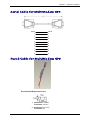
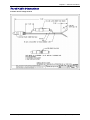
MultiModem Wireless Modems EDGE, GPRS, CDMA with GPS Functionality MTCBA-E-GP MTCBA-G-GP-Fx MTCBA-C-GP-Nx User Guide Copyright and Technical Support User Guide MultiModem Wireless EDGE, GPRS, and CDMA Modems with GPS Functionality MTCBA-E-GP, MTCBA-G-GP-Fx, MTCBA-C-GP-Nx S000376A, Revision A Copyright This publication may not be reproduced, in whole or in part, without prior expressed written permission from MultiTech Systems, Inc. All rights reserved. Copyright © 2006 by Multi-Tech Systems, Inc. Multi-Tech Systems, Inc. makes no representations or warranty with respect to the contents hereof and specifically disclaims any implied warranties of merchantability or fitness for any particular purpose. Furthermore, Multi-Tech Systems, Inc. reserves the right to revise this publication and to make changes from time to time in the content hereof without obligation of Multi-Tech Systems, Inc. to notify any person or organization of such revisions or changes. Record of Revisions Revision Date A 03/07/06 Description Initial release. Includes the Waste Electrical and Electronic Equipment Statement. Trademarks Trademarks and registered trademarks of Multi-Tech Systems, Inc. include MultiModem, the Multi-Tech logo, and Multi-Tech. Windows is a registered trademark of Microsoft Corporation in the United States and other countries. All products or technologies mentioned in this guide are the trademarks or registered trademarks of their respective holders. Technical Support Country France India Europe, Asia, Africa U.S., Canada, all others By Email [email protected] [email protected] [email protected] [email protected] By Phone +(33) 1-64 61 09 81 +(91) 124-2340780 +(44) 118 959 7774 800-972-2439 or +763-785-3500 World Headquarters Multi-Tech Systems, Inc. 2205 Woodale Drive Mounds View, Minnesota 55112 (763) 785-3500 or (800) 328-9717 Fax 763-785-9874 Internet Address: http://www.multitech.com Multi-Tech Systems, Inc. MultiModem Wireless EDGE, GPRS, and CDMA Modems with GPS (S000376A) 2 Table of Contents Table of Contents Chapter 1 – Introduction and Product Description ................................................................................... 4 GPS Interface............................................................................................................................................................4 MultiModem EDGE ...................................................................................................................................................4 MultiModem GPRS ...................................................................................................................................................4 MultiModem CDMA ..................................................................................................................................................4 Safety Warnings .......................................................................................................................................................5 General Safety.................................................................................................................................................5 Vehicle Safety..................................................................................................................................................5 Maintenance of the Wireless MultiModem .......................................................................................................5 Handling Precautions.......................................................................................................................................5 Safety Recommendations for Rack Installations..............................................................................................6 Ship Kit Contents .....................................................................................................................................................6 Wireless Modem Specifications..............................................................................................................................7 GPS Specifications ..................................................................................................................................................8 Key Features ...................................................................................................................................................8 Performance ....................................................................................................................................................8 Interface...........................................................................................................................................................8 The Front Panel ........................................................................................................................................................9 LEDs ................................................................................................................................................................9 Modem LEDs ...................................................................................................................................................9 Chapter 2 – Setup and Configuration ....................................................................................................... 10 Back Panel of the MultiModem with GPS.............................................................................................................10 S1/S2 Switches..............................................................................................................................................10 Configuring the Wireless Modem Side of the MultiModem ................................................................................10 1. Hardware Setup ........................................................................................................................................10 2. SIM Card for GPRS or EDGE ...................................................................................................................11 3. Establish a Wireless Account....................................................................................................................11 4. Establish Internet Access..........................................................................................................................11 5. Login Using TTY .......................................................................................................................................12 6. Using AT Commands to Test Your Modem ..............................................................................................12 Configuring the GPS Side of the MultiModem.....................................................................................................13 1. Port Configuration .....................................................................................................................................13 2. Hardware Setup ........................................................................................................................................14 3. Verify the GPS Connection .......................................................................................................................14 Chapter 3 – Setup/Configuration Examples............................................................................................. 15 Application Example 1...........................................................................................................................................15 Application Example 2...........................................................................................................................................16 Chapter 4 – Antennas and Cables ............................................................................................................ 17 The Antenna ...........................................................................................................................................................17 EDGE, GSM, and CDMA Antenna.................................................................................................................17 EDGE and GSM Radio Characteristics..........................................................................................................17 CDMA Radio Characteristics .........................................................................................................................17 GSM / CDMA Antenna Example....................................................................................................................17 GPS Antenna Compact Magnetic Mount Antenna ..............................................................................................18 Serial Cable for MultiModem GPS ........................................................................................................................20 Fused Cable for MultiModem GPS........................................................................................................................20 Fused Cable Dimensions...............................................................................................................................21 Appendix A – Multi-Tech Systems, Inc. Warranty and Repair Policies ................................................ 22 Multi-Tech Warranty Statement ............................................................................................................................22 Appendix B – Waste Electrical and Electronic Equipment .................................................................... 24 Index............................................................................................................................................................. 25 Multi-Tech Systems, Inc. MultiModem Wireless EDGE, GPRS, and CDMA Modems with GPS (S000376A) 3 Chapter 1 – Introduction and Product Description Chapter 1 – Introduction and Product Description This User Guide describes the MultiModem Wireless EDGE, GPRS, and CDMA modems with GPS functionality. Your product choice depends on the technology (cellular network) available to you. Product MTCBA-C-GP-Nx MTCBA-E-GP MTCBA-G-GP-Fx Your Cellular Network CDMA EDGE GPRS Interface GPS GPS GPS GPS Interface The MultiModem EDGE, GPRS, or CDMA wireless modem with GPS incorporates an internal Trimble Lassen iQ GPS module providing 12-channel GPS functionality. It delivers complete position, velocity, and time (PVT) solutions making it ideal for real-time vehicle tracking, navigation, and fleet management applications. The GPS functionality supports four of the most popular protocols: NMEA 0183, DGPS (RTCM), TSIP (Trimble Standard Interface Protocol), and TAIP (Trimble ASCII Interface Protocol) and provides dual sensitivity modes allowing it to automatically switch to higher sensitivity when satellite signals are weak. The MultiModem EDGE, GPRS, or CDMA wireless modem with GPS utilizes an RS-232 interface. The GPS information is received on a secondary serial port and can be used for in-vehicle navigation. In addition, the data can be sent through the wireless modem to a central, real-time tracking server via SMS or GPRS. The MultiModem EDGE, GPRS, or CDMA wireless modem provides flexibility to allow third party GPS applications and Application Service Providers (ASPs) the ability to customize their software to work with the wireless modem hardware. MultiModem EDGE The MultiModem® EDGE wireless modem delivers some of the fastest cellular wireless data speeds utilizing EDGE technology. It allows users to connect to the Internet and send and receive data up to three times faster than possible with an ordinary GSM/GPRS network making it ideal for highly data-intensive multimedia applications. The MultiModem EDGE wireless modem is equipped with quad-band GSM, which means it can be used worldwide on all existing GSM networks. AT Commands The MultiModem EDGE wireless modem is configured using the EDGE AT Commands. These commands are documented in the Reference Guide for the MultiModem Wireless EDGE Modems, document number S000371x located on the MultiModem CD included in your ship kit. MultiModem GPRS The MultiModem® GPRS wireless modem offers standards-based multi-band GSM/GPRS Class 10 performance. It supports GSM circuit-switched cellular data connections, offers SMS features, and includes an embedded TCP/IP protocol stack. AT Commands The MultiModem GPRS wireless modem is configured using the GPRS AT Commands. These commands are documented in the Reference Guide for the MultiModem Wireless GPRS Modems, document number S000293x and also the Reference Guide for the GSM IP Commands, document number S000333x located on the MultiModem CD included in your ship kit. MultiModem CDMA The MultiModem® CDMA wireless modem offers standards-based multi-band CDMA200 1xRTT performance. It supports CDMA IS-95A and IS-95B circuit-switched cellular data connections and offers SMS services. AT Commands The MultiModem CDMA wireless modem is configured using the CDMA AT Commands. These commands are documented in the Reference Guide for the MultiModem Wireless CDMA Modems, document number S000294x located on the MultiModem CD included in your ship kit. Multi-Tech Systems, Inc. MultiModem Wireless EDGE, GPRS, and CDMA Modems with GPS (S000376A) 4 Chapter 1 – Introduction and Product Description Safety Warnings General Safety The modem is designed and intended to be used in either fixed or mobile applications. In the “Fixed” application, the device is physically secured at one location and not easily moved to another location. In the “Mobile” application, the device may be regularly moved to different locations. Caution! Maintain a separation distance of at least 20 cm (8 inches) between the transmitter’s antenna and the body of the user or nearby persons. The modem is not designed for, nor intended to be, used in applications within 20 cm (8 inches) of the body of the user. Such uses are strictly prohibited. Avoid possible radio frequency (RF) interference by carefully following the safety guidelines below. • Switch OFF the MultiModem in the vicinity of gasoline or diesel-fuel pumps or before filling a vehicle with fuel. • Switch OFF the MultiModem in hospitals and any other place where medical equipment may be in use. • Respect restrictions on the use of radio equipment in fuel depots, chemical plants, or where blasting operations are in progress. • There may be a hazard associated with the operation of your MultiModem in the vicinity of inadequately protected personal medical devices such as hearing aids and pacemakers. Consult the manufacturers of the medical device to determine if it is adequately protected. • Operation of the MultiModem in the vicinity of other electronic equipment may cause interference if the equipment is inadequately protected. Observe any warning signs and manufacturers’ recommendations. Vehicle Safety • Do not use your MultiModem while driving. • Respect national regulations on the use of cellular telephones in vehicles. Road safety always comes first. • If incorrectly installed in a vehicle, the operation of MultiModem telephone could interfere with the correct functioning of vehicle electronics. To avoid such problems, be sure that the installation has been performed by qualified personnel. Verification of the protection of vehicle electronics should be part of the installation. • The use of an alert device to operate a vehicle’s lights or horn on public roads is not permitted. Maintenance of the Wireless MultiModem Your wireless MultiModem is the product of advanced engineering, design, and craftsmanship and should be treated with care. The suggestions below will help you to enjoy this product for many years. • Do not expose the MultiModem to any extreme environment where the temperature or humidity is high. • Do not attempt to disassemble the MultiModem. There are no user serviceable parts inside. • Do not expose the MultiModem to water, rain, or spilled beverages. It is not waterproof. • Do not abuse your MultiModem by dropping, knocking, or violently shaking it. Rough handling can damage it. • Do not place the MultiModem alongside computer discs, credit or travel cards, or other magnetic media. The information contained on discs or cards may be affected by the phone. • The use of accessories not authorized by Multi-Tech or not compliant with Multi-Tech’s accessory specifications may invalidate the warranty of the MultiModem. • In the unlikely event of a fault in the MultiModem, contact Multi-Tech Technical Support. Handling Precautions All devices must be handled with certain precautions to avoid damage due to the accumulation of static charge. Although input protection circuitry has been incorporated into the devices to minimize the effect of this static build up, proper precautions should be taken to avoid exposure to electrostatic discharge during handling and mounting. Multi-Tech Systems, Inc. MultiModem Wireless EDGE, GPRS, and CDMA Modems with GPS (S000376A) 5 Chapter 1 – Introduction and Product Description Safety Recommendations for Rack Installations • • • • • • • • Ensure proper installation in a closed or multi-unit enclosure by following the recommended installation as defined by the enclosure manufacturer. If installing the wireless modem in a closed or multi-unit enclosure, ensure adequate airflow so that the maximum recommended ambient temperature is not exceeded. Do not place the device directly on top of other equipment or place other equipment directly on top of this device. Ensure that the device is properly connected to earth ground via a grounded power cord. If a power strip is used, ensure that the power strip also provides adequate grounding. Ensure that the main supply circuit is capable of handling the load. See the power label on the device for requirements. Maximum ambient temperature is 70 degrees Celsius. This device should be installed by properly qualified personnel. Only connect like circuits; e.g., connect SELV (Secondary Extra Low Voltage) circuits to SELV circuits and TN (Telecommunications Network) circuits to TN circuits. Ship Kit Contents The single wireless modem is shipped with the following: • • • • • • One MultiModem GPRS/EDGE/CDMA wireless modem with GPS functionality. One fused DC power cable. Four rubber feet for desktop placement. Printed Activation Customer Notices (for Cingular, Sprint, Verizon networks, and general CDMA activation). One printed Quick Start Guide. One MultiModem CD that provides documentation, two GPS utility programs (iQ Monitor.exe and iQ Chat.exe), and Adobe Acrobat Reader. The GPS Developer Kit is shipped with the following: • • • • • • • • Three power cords. One fused DC power cable. One universal power supply. Two serial cables. Some international kits may have three antennas (two wireless antennas and one GPS antenna). Printed Customer Activation Notices (for Cingular, Sprint, Verizon networks, and general CDMA activation). One printed Quick Start Guide. One MultiModem CD that provides documentation, two GPS utility programs (iQ Monitor.exe and iQ Chat.exe), and Adobe Acrobat Reader. Multi-Tech Systems, Inc. MultiModem Wireless EDGE, GPRS, and CDMA Modems with GPS (S000376A) 6 Chapter 1 – Introduction and Product Description Wireless Modem Specifications Features EDGE Modem GPRS Modem CDMA Modem EDGE: E-GPRS Class 10 GPRS: Class 12 Band, Quad-band GSM Frequency 850/900/1800/1900 MHz Packet Data EDGE: E-GPRS Up to 240K bps, Coding scheme MCS 1-9, Mobile station Class B, LLC layer, 4 time slots GPRS: GPRS Class 12, Full PBCCH support, Coding scheme 14, Mobile station Class B CircuitAsynchronous, transparent and Switched Data non-transparent up to 14.4K bps Fax Class 1 Group 3 Short Message Text & PDU, Point-to-Point MO & Services-SMS MT, cell broadcast Internet TCP, UDP, DNS, FTP, SMTP, POP3, HTTP Protocols Supported GPRS Class 10 CDMA2000 1xRTT Dual-band 850/1900 or 900/1800 MHz GSM/GPRS Up to 85.5K bps PBCCH support Coding schemes: CS1 to CS4 Dual-band 800/1900 MHz CDMA; 800 MHz with R-UIM support Up to 153.6K bps forward and reverse Asynchronous, transparent and non-transparent up to 14.4K bps GSM Class 1 and Class 2 Group 3 Text & PDU, Point-to-Point, cell broadcast ARP, Dial-in PPP, DNS Resolve, FTP client, ICMP, IP, IPCP, LCP, POP3 (receive mail), PPP, SMTP (send mail), TCP socket, Telnet client, Telnet server, UDP socket, CHAP, PAP NA IS-95A, IS 95B up to 14.4K bps RF Antenna: 50 ohm SMA GPS Antenna: 50 ohm SMA Standard 3V SIM receptacle (2) DB-9 RF Antenna: 50 ohm SMA GPS Antenna: 50 ohm SMA NA (2) DB-9 2.5mm miniature screw 2.5mm miniature screw NA NA 5V to 32 VDC 5V to 32 VDC Performance Class 2.0 Group 3 ASCII Text & UCS-2, Point-to-Point, cell broadcast Dial-in PPP, DNS, FTP, HTTP, ICMP, IP, IPCP, LCP, POP3, PPP, SMTP, SNMP, SNTP, TCP, Telnet, TFTP & UDP Voice Features Half rate (HR), Full rate (FR), Enhanced full rate (EHR), Adaptive multi rate (AMR). Basic hands free operation with echo cancellation and noise reduction Antenna RF Antenna: 50 ohm SMA Connectors GPS Antenna: 50 ohm SMA SIM Connector Standard 3V SIM receptacle Interface (2) DB-9 Connectors Power 2.5mm miniature screw Connectors Voice RJ-9 4-pos modjack Connectors Power 5V to 32 VDC Requirements Physical 2.8" L x 6.4" W x 1.2" H; 11.5 oz. Description (7.1 cm x 16.3 cm x 3.0 cm; 326g) Operating 0° to +50° C Environment Humidity 20% to 90% non-condensing Certifications CE Mark, R&TTE EMC: FCC Part 2, 15 Class A, 22, 24 EN 55022 EN 55024 Safety: cUL, UL 60950; EN 60950 Network: PTCRB Miscellaneous AT Command Compatible Desktop or panel mounting Carrier approved Numerous LEDs provide status Embedded TCP/IP stack 2.8" L x 6.4" W x 1.2" H; 11.5 oz. (7.1 cm x 16.3 cm x 3.0 cm; 326g) 0° to +50° C 2.8" L x 6.4" W x 1.2" H; 11.5 oz. (7.1 cm x 16.3 cm x 3.0 cm; 326g) 0° to +50° C 20% to 90% non-condensing CE Mark, R&TTE EMC: FCC Part 2, 15 Class A, 22, 24 EN 55022 EN 55024 Safety: cUL, UL 60950; EN 60950 Network: PTCRB AT Command Compatible Desktop or panel mounting Carrier approved Numerous LEDs provide status Embedded TCP/IP stack 20% to 90% non-condensing EMC: FCC Part 2, 15 Class A, 22, 24 EN 55022 EN 55024 Safety: cUL, UL 60950; EN 60950 Network: PTCRB Warranty Two years Two years NA AT Command Compatible Desktop or panel mounting Carrier approved Numerous LEDs provide status CDG 1 and 2 network certified CDMA IS-95A, IS-95B backwards compatible Two years Multi-Tech Systems, Inc. MultiModem Wireless EDGE, GPRS, and CDMA Modems with GPS (S000376A) 7 Chapter 1 – Introduction and Product Description GPS Specifications Key Features • 12-channel simultaneous operation • Dual sensitivity modes with automatic switching • Aided GPS through TSIP • Antenna open and short circuit detection and protection • Supports NMEA 0183, TSIP, and TAIP, DGPS protocols • DGPS capable Performance General Update Rate Accuracy Acquisition L1 frequency (1575.42 MHz), C/A code (Standard Positioning Service), 12-channel, continuous tracking receiver TSIP @ 1 Hz; NMEA @ 1 Hz; TAIP @ 1Hz Horizontal: <5 meters (50%), <8 meters (90%) Altitude: <10 meters (50%), <16 meters (90%) Velocity: 0.06 m/sec. PPS (static): ±50 nanoseconds (Autonomous Operation in Standard Sensitivity Mode) Reacquisition: <2 sec. (90%) Hot Start: <10 sec. (50%), <13 sec. (90%) Warm Start: <38 sec. (50%), <42 sec. (90%) Cold Start: <50 sec. (50%), <84 sec. (90%) (Cold Start requires no initialization. Warm Start implies that the last position, time, and almanac are saved by backup power. Hot start implies ephemeris also saved. Optional (COCOM) Limits Altitude: 18,000 m Velocity: 515 m/s Either limit may be exceeded, but not both. Interface PPS Protocols NMEA 3.3 V CMOS-compatible TTL-level pulse Once per second TSIP, TAIP, NMEA 0183 v3.0, RTCM SC-104 GGA, VTG, GLL, ZDA, GSA, GSV and RMC Messages selectable by TSIP command; selection stored in flash memory. Multi-Tech Systems, Inc. MultiModem Wireless EDGE, GPRS, and CDMA Modems with GPS (S000376A) 8 Chapter 1 – Introduction and Product Description The Front Panel The MultiModem wireless EDGE modem with GPS functionality has 8 LEDs, 5 of which are modem LEDs, and a SIM card. The MultiModem wireless GPRS modem with GPS functionality has the same LEDs and SIM card as the EDGE modem. The MultiModem wireless CDMA modem with GPS functionality has the same LEDs as the EDGE and GPRS modem, but it does not, however, have a SIM card. LEDs PWR POWER. GPS GPS. Blinks to show GPS is active. IP IP FUNCTION. This LED blinks when the IP function of the modem is operating normally. It shows a steady light when powering-up, initializing, or flashing the firmware. Modem LEDs TD RD CD TR LS TRANSMIT DATA. This LED blinks when the modem is transmitting data to your wireless carrier. RECEIVE DATA. This LED blinks when the modem is receiving data from your wireless carrier. CARRIER DETECT. This LED lights when the modem detects a valid carrier signal from a wireless carrier. (DATA) TERMINAL READY. This LED lights when the modem is trying to establish a wireless connection. LINK STATUS. This LED blinks when there is a valid wireless signal. When it is on or off, the wireless strength is low. Multi-Tech Systems, Inc. MultiModem Wireless EDGE, GPRS, and CDMA Modems with GPS (S000376A) 9 Chapter 2 – Setup and Configuration Chapter 2 – Setup and Configuration Back Panel of the MultiModem with GPS The back panel view is included to help you understand the MultiModem setup. MultiModem with GPS Interface Back Panel S1/S2 Switches Note: The switches as shown in the diagram above are located behind a cover plate that can be removed when you need to change the switch settings. S1: Down puts the MultiModem in reset state. Up runs the MultiModem properly. Toggle the S1 switch down and back up to reset the MultiModem. S2: Up keeps the GPS data signals separate from the wireless modem. Down allows GPS data from Port 1 to flow to the wireless modem’s data in signal. Configuring the Wireless Modem Side of the MultiModem 1. Hardware Setup 1. 2. 3. 4. Using an RS-232 cable, connect a workstation to the GSM/CDMA connector on the MultiModem. Attach both antennas. The GPS antenna is a 50 ohm SMA antenna. The GSM/CDMA antenna is a standard SMA antenna. Switches S1 and S2 should be in the default positions – both up. Plug one end of the power cord into the MultiModem and the other end into a live power outlet. The PWR LED lights up. Warning: Do not connect your wireless modem directly to a vehicle’s battery for your power source. Doing so may cause power spikes. If you wish to use the battery as a power source, add a filtering device to the DC input. Multi-Tech Systems, Inc. MultiModem Wireless EDGE, GPRS, and CDMA Modems with GPS (S000376A) 10 Chapter 2 – Setup and Configuration 2. SIM Card for GPRS or EDGE The wireless modem requires the power supply connection to begin operation. It also requires a SIM card (Subscriber Identity Module) to operate on a GPRS or EDGE network. To install the SIM card: 1. Use a small screwdriver to remove the screw closest to the outside edge of the modem. Then swing the loosened SIM slot cover up and over to the left. 2. Insert the SIM card into the SIM card slot. The following graphic illustrates the correct SIM card orientation. SIM AT Commands SIM Commands for GPRS SIM commands are included in the GPRS AT Commands Reference Guide. SIM Commands for EDGE SIM commands are covered in a separate guide entitled SIM Application Toolkit – AT Commands Reference Guide. 3. Establish a Wireless Account Obtain a wireless account through a Wireless Service Provider. This will allow you to use the service provider's network; for example, Cingular, Sprint, and Verizon. Cingular and Sprint: Contact Multi-Tech, a certified national activation agent for Cingular and Sprint to set up one of these accounts. Verizon and Others: For Verizon and other accounts, contact their activation agents directly. Activations Instructions: See the Cingular, Sprint, Verizon, and general Customer Activation Customer Notices included with your modem for a list of the information you must give to the activation agent. You will receive, depending upon your provider, one or two phone numbers and a service programming code or lock code. Write these numbers down as you will have to use them to configure the wireless modem. If you have any questions or want to set up your account, contact Multi-Tech Systems, Inc. at: 800-972-2439 or 763-717-5863. 4. Establish Internet Access Internet Access Using: • GSM with GPRS • CDMA 1x Data A single DUN number is generally used by all of a wireless provider’s subscribers throughout its area of coverage – regional, nationwide, continental, etc. Rather than being a literal phone directory number, as in conventional DUN, this is a code that gives the modem Internet access. Internet Access Using: • GSM without GPRS • CDMA Point-to-Point Data A circuit-switched data connection is used. Use the dial-up-network (DUN) to make a conventional V.32 modem connection to any terminating modem at the other end. The phone number specified in the DUN can be one supplied by the wireless service provider or another phone number related to a different dialup modem service (e.g., a dialup modem service phone number from any commercial or private dialup network). Multi-Tech Systems, Inc. MultiModem Wireless EDGE, GPRS, and CDMA Modems with GPS (S000376A) 11 Chapter 2 – Setup and Configuration 5. Login Using TTY • Use TTY to configure your IP module for the first time. Configure the host serial port using the defaults listed below: Baud: 115.2K Data: 8 Parity: N Stop: 1 Flow-Control: None • Press the Enter key three times to get to the Login prompt. • At the Login prompt, type admin. • At the Password prompt, type admin. Important: User name and password are case sensitive. They must be typed in lowercase letters. • Then type dialout serial s1 to start a dialout session. Dialout serial s1 is used to initiate a dialout session to the modem. You can now enter AT commands to test your modem. 6. Using AT Commands to Test Your Modem 1. Check the signal quality. This command determines the received signal strength indication (<rssi>) • Type AT+CSQ Modem responds with the received signal strength (<rssi>). Response 0 means -113 dBm or less Response 1 means -111 dBm Response 2 to 30 means -109 to -53 dBm Response 31 means -51 dBm or greater Response 99 means not known or detectable 2. Check the identity of the modem. Use this command: ATI (AT is followed by the capital letter i). • Type ATI0 (The command ends in a zero). Manufacturing data displays: Wavecom Modem 800 1900 • Type ATI3 Software version displays. Ex: S/W VER: xxxxx • Type ATI6 Capability data displays. Ex: +CGSM, +CIS707, ... 3. Check the network registration and roaming status. • Type AT+CREG? The modem will respond in one of the following ways: +CREG: 0,0 (this tells you the modem is not registered on any network) +CREG: 0,1 (this tells you the modem is registered on the home network) +CREG: 0,5 (this tells you the modem is registered on a network but it is roaming) Multi-Tech Systems, Inc. MultiModem Wireless EDGE, GPRS, and CDMA Modems with GPS (S000376A) 12 Chapter 2 – Setup and Configuration Configuring the GPS Side of the MultiModem 1. Port Configuration The GPS receiver module has two I/O ports. The table below provides the default protocols and port configurations for the receiver, as delivered from the factory. TSIP IN/OUT is the default protocol on Port 1 and RTCM-IN and NMEA-OUT is the default protocol on Port 2. Default Protocols and Port Configurations Port Input Default Setup Protocol 1 TSIP Baud Rate: 9600 Data Bits: 8 Parity: Odd Stop Bits: 1 No Flow Control 2 RTCM Baud Rate: 4800 Data Bits: 8 Parity: None Stop Bits: 1 No Flow Control Output Default Setup Language TSIP Baud Rate: 9600 Data Bits: 8 Parity: Odd Stop Bits: 1 No Flow Control NMEA Baud Rate: 4800 Data Bits: 8 Parity: None Stop Bits: 1 No Flow Control The GPS Receiver can also be configured to output TAIP messages. The standard port characteristics for TAIP are: • • • • • Baud Rate: 4800 Data Bits: 8 Parity: None Stop Bits:1 No Flow Control GPS DB-9: Pin 2 = Port 1 Transmit Data from GPS Pin 3 = Port 1 Receive Data into GPS Pin 6 = Port 2 Transmit Data from GPS Pin 4 = Port 2 Receive Data into GPS Pin 5 = GND Any standard serial communications program, such as Windows Hyper-Terminal or PROCOMM, can be used to view the NMEA or TAIP output messages. TSIP is a binary protocol and outputs raw binary serial data that cannot be read when using Windows Terminal or PROCOMM. To view the output of the TSIP protocol in text format, use the iQ_CHAT or the iQ_Monitor program. These programs are included on the CD-ROM as part of the MultiModem GPS Developer’s Kit. About iQ_Monitor and iQ_Chat Utilities The iQ_Monitor.exe and iQ_Chat.exe files plus a Developer’s Guide entitled Developing a Software Interface for the GPS Module in the Multi-Tech MultiModem are included on the CD as part of the MultiModem Developer’s Kit. iQ_Monitor iQ_Monitor is used to verify GPS is functioning. The Developer Guide explains how to setup and use this utility. It is a 32-bit Windows application that interfaces with a TSIP-speaking receiver through the GPS serial port. The program accepts TSIP reports and displays these fields in a window: Position, Velocity, Time, Receiver Status, and Satellite Track Status. The program allows you to exercise some basic TSIP commands and can also log a TSIP report in binary format for later translation. iQ_Chat iQ_Chat is a 16-bit DOS-based application that interfaces with the GPS receiver through a serial port. It allows you to exercise TSIP commands, configure the GPS receiver for NMEA or TAIP, and view NMEA or TAIP output. It also logs a TSIP report in binary format. Multi-Tech Systems, Inc. MultiModem Wireless EDGE, GPRS, and CDMA Modems with GPS (S000376A) 13 Chapter 2 – Setup and Configuration 2. Hardware Setup 1. Using an RS-232 cable, connect a workstation to the GPS connector on the MultiModem. 2. Attach both antennas (included in your ship kit). The GPS antenna is a 50 ohm SMA antenna. The GSM/ CDMA antenna is a standard SMA antenna. 3. Plug one end of the power cord into the device and the other end into a live power outlet. The PWR LED lights up. Warning: Do not connect your wireless modem directly to a vehicle’s battery for your power source. Doing so may cause power spikes. If you wish to use the battery as a power source, add a filtering device to the DC input. 3. Verify the GPS Connection The workstation should be running a utility, such as iQ_Monitor, to monitor GPS satellite signals. iQ_Monitor is included on the product CD with the MultiModem Developer’s Kit. Multi-Tech Systems, Inc. MultiModem Wireless EDGE, GPRS, and CDMA Modems with GPS (S000376A) 14 Chapter 3 – Setup/Configuration Examples Chapter 3 – Setup/Configuration Examples Application Example 1 In this example, the GPS side of the MultiModem is monitoring GPS locations and the wireless modem side of the MultiModem is waiting for incoming data. A portable workstation, such as a laptop or handheld PC, is connected to this wireless modem to both serial ports – the GSM/CDMA port and the GPS port. 1. Using an RS-232 cable, connect the GPS connector jack to portable PC’s serial port. 2. Using an RS-232 cable, connect the GSM/CDMA jack to the PC’s other serial port. 3. Attach both antennas (the GPS antenna and the GSM/ CDMA antenna). 4. Set both the S1 and S2 switches up (the default). If you have not changed the switches previously, then they will be in the default position. Note that the switches are located behind a cover plate on the connector side of the modem. The cover plate can be removed when you need to change the switch settings. 5. Connect to a power source; for example, to a cigarette outlet on a vehicle. 6. Run your software application that reads GPS data from the GPS serial port. The wireless modem is available to the portable PC for transferring data. 7. Your central tracking station can then retrieve the data wirelessly from your CDMA, GPRS, or EDGE network provider connection. Multi-Tech Systems, Inc. MultiModem Wireless EDGE, GPRS, and CDMA Modems with GPS (S000376A) 15 Chapter 3 – Setup/Configuration Examples Application Example 2 This example shows the MultiModem GRPS Wireless Modem with GPS mounted in a truck that can be tracked by a GPS satellite. This configuration shows a MultiModem located in a vehicle and not connected to a portable PC. The MultiModem in this example simply reads the GPS data as it is sent from GPS satellite, and then it broadcasts the data to your central tracking system by way of your CDMA, GPRS, or EDGE network provider connection. Note that in this example, you cannot configure the GPS; you can only receive data from port 1 of the GPS. 1. Mount the MultiModem in a vehicle. 2. Attach both antennas (the GPS antenna and the GSM/ CDMA antenna). 3. Verify the S1 switch up (the default). 4. Set the S2 switch down. This allows data from the GPS port 1 to flow to the wireless modem side of the MultiModem. Then, when you call into this modem from a remote location, the GPS data is displayed on the remotely located workstation’s screen. Note that the workstation can be a laptop or a handheld device. 5. Connect to a power source; for example, to a cigarette outlet on a vehicle. 6. Your central tracking station can then retrieve the data wirelessly from your CDMA, GPRS, or EDGE network provider connection. Multi-Tech Systems, Inc. MultiModem Wireless EDGE, GPRS, and CDMA Modems with GPS (S000376A) 16 Chapter 4 – Antennas and Cables Chapter 4 – Antennas and Cables The Antenna The antenna sub-system and integration in the application is a major issue: Choice of antenna (type, length, performances, thermal resistance, etc.) These elements could affect GSM performances such as sensitivity and emitted power. EDGE, GSM, and CDMA Antenna The integrated modem antenna connector is a SMA connector. The SMA connector incorporates a 'Screw-on' action in order to make the connection easier while providing an excellent RF performance. An additional advantage is its small physical size, which is 50% of the standard MCX connector. This type of connector is suitable for the standard ranges of flexible and semi-rigid cables. The characteristic impedance of the MMCX coaxial connector is 50 ohm. The antenna manufacturer must guarantee that the antenna will be working according to the radio characteristics presented in the table below. EDGE and GSM Radio Characteristics GSM 850 Frequency RX 869 to 894 MHz Frequency TX 824 to 849 MHz RF Power Stand 2W at 12.5% duty cycle Impedance VSWR Typical Radiated Gain E-GSM 900 GSM 1800 925 to 960 MHz 1805 to 1880 MHz 880 to 915 MHz 1710 to 1785 MHz 2W at 12.5% duty cycle 1W at 12.5% duty cycle 50 ohms <2 0 dBi on azimuth plane GSM 1900 1930 to 1990 MHz 1850 to 1910 MHz 1W at 12.5% duty cycle CDMA Radio Characteristics Frequency RX Frequency TX Impedance VSWR Typical Radiated Gain CDMA 800 869 to 894 MHz 824 to 849 MHz CDMA 1900 1930 to 1990 MHz 1850 to 1910 MHz 50 ohms <2 0 dBi in at least one direction GSM / CDMA Antenna Example An antenna that meets the requirements for use with this product is included with your purchase. Multi-Tech Systems, Inc. MultiModem Wireless EDGE, GPRS, and CDMA Modems with GPS (S000376A) 17 Chapter 4 – Antennas and Cables GPS Antenna Compact Magnetic Mount Antenna Antenna Frequency Range Gain Polarization Axial Ratio 1,575.42+/-1.023MHz 90°: 3.0dBi min.; 20°: -4.0dBi min. (mounted on the 65mm X 65mm square ground plane) RHCP 90°: 4.0dB max.; 10°: 6.0dB max. (mounted on the 65mm X 65mm square ground plane) LNA Frequency Range Gain Noise Out of band rejection Output Impedance Output VSWR 1,575.42 ±1.023MHz 28 ±3 dB (-40°C to 85°C) 1.5dB max. (+25°C ± 5°C) 2.2dB max. (+85°C) fo=1,575.42MHz fo±20MHz 7dB min. fo±30MHz 12dB min. fo+/-50MHz 20dB min. fo±100MHz 30dB min. 50Ω 2.0max. Overall Specifications Frequency Range Gain Output Impedance VSWR ESD MTBF 1,575.42 ± 1.023MHz 27 ± 3dBi (+25°C ± 5°C) 27 ± 4dBi (-40°C to 85°C) (mounted on the 65mm x 65mm square ground plane) 50Ω 2.0MAX. Antenna surface ± 15KV Connector pin ± 8KV 5.13E+6Hr. Storage Conditions Temperature and Humidity -20°C to 45°C, humidity 80% max. consumption at room temperature General Operating Temp. Storage Temp. Relative Humidity Input voltage Power Cons. Output connection Cable Weight -40°C to + 85°C -40°C to + 100°C 20% to 95% 3.0V ± 0.3V 15mA max (room temp) MCX (plug) 1.5DS-QEHV (Shikoku Cable Co.) black: 5m 20g TYP Multi-Tech Systems, Inc. MultiModem Wireless EDGE, GPRS, and CDMA Modems with GPS (S000376A) 18 Chapter 4 – Antennas and Cables Multi-Tech Systems, Inc. MultiModem Wireless EDGE, GPRS, and CDMA Modems with GPS (S000376A) 19 Chapter 4 – Antennas and Cables Serial Cable for MultiModem GPS DE-9P DE-9S 1 1 2 2 3 3 4 4 5 5 6 6 7 7 8 8 9 9 Fused Cable for MultiModem GPS Recommended Replacement Fuses 1. Manufacturer: Littelfuse Part Number: 313 02.5 2. Manufacturer: Sun Fuse Part Number: 6S Multi-Tech Systems, Inc. MultiModem Wireless EDGE, GPRS, and CDMA Modems with GPS (S000376A) 20 Chapter 4 – Antennas and Cables Fused Cable Dimensions Includes: How to Change the Fuse Multi-Tech Systems, Inc. MultiModem Wireless EDGE, GPRS, and CDMA Modems with GPS (S000376A) 21 Appendix A – Multi-Tech Systems, Inc. Warranty and Repair Policies Appendix A – Multi-Tech Systems, Inc. Warranty and Repair Policies Multi-Tech Warranty Statement Multi-Tech Systems, Inc., (hereafter “MTS”) warrants that its products will be free from defects in material or workmanship for a period of two, five, or ten years (depending on model) from date of purchase, or if proof of purchase is not provided, two, five, or ten years (depending on model) from date of shipment. MTS MAKES NO OTHER WARRANTY, EXPRESS OR IMPLIED, AND ALL IMPLIED WARRANTIES OF MERCHANTABILITY AND FITNESS FOR A PARTICULAR PURPOSE ARE HEREBY DISCLAIMED. This warranty does not apply to any products which have been damaged by lightning storms, water, or power surges or which have been neglected, altered, abused, used for a purpose other than the one for which they were manufactured, repaired by Customer or any party without MTS’s written authorization, or used in any manner inconsistent with MTS’s instructions. MTS’s entire obligation under this warranty shall be limited (at MTS’s option) to repair or replacement of any products which prove to be defective within the warranty period or, at MTS’s option, issuance of a refund of the purchase price. Defective products must be returned by Customer to MTS’s factory — transportation prepaid. MTS WILL NOT BE LIABLE FOR CONSEQUENTIAL DAMAGES, AND UNDER NO CIRCUMSTANCES WILL ITS LIABILITY EXCEED THE PRICE FOR DEFECTIVE PRODUCTS. Repair Procedures for U.S. and Canadian Customers In the event that service is required, products may be shipped, freight prepaid, to our Mounds View, Minnesota factory: Multi-Tech Systems, Inc. 2205 Woodale Drive Mounds View, MN 55112 Attn: Repairs, Serial # ____________ A Returned Materials Authorization (RMA) is not required. Return shipping charges (surface) will be paid by MTS to destinations in U.S. and Canada. Please include, inside the shipping box, a description of the problem, a return shipping address (must have street address, not P.O. Box), your telephone number, and if the product is out of warranty, a check or purchase order for repair charges. For out of warranty repair charges, go to COMPANY/Policies/warranty/ Extended two-year overnight replacement service agreements are available for selected products. Please call MTS customer service at (888) 288-5470 or visit our web site at http://www.multitech.com/PARTNERS/Programs/overnight_replacement/ for details on rates and coverage’s. Please direct your questions regarding technical matters, product configuration, verification that the product is defective, etc., to our Technical Support department at (800) 972-2439 or email [email protected]. Please direct your questions regarding repair expediting, receiving, shipping, billing, etc., to our Repair Accounting department at (800) 328-9717 or (763) 717-5631, or email [email protected]. Repairs for damages caused by lightning storms, water, power surges, incorrect installation, physical abuse, or usercaused damages are billed on a time-plus-materials basis. Multi-Tech Systems, Inc. MultiModem Wireless EDGE, GPRS, and CDMA Modems with GPS (S000376A) 22 Appendix A – Multi-Tech Systems, Inc. Warranty and Repair Policies Repair Procedures for International Customers (Outside U.S.A. and Canada) Your original point of purchase Reseller may offer the quickest and most economical repair option for your Multi-Tech product. You may also contact any Multi-Tech sales office for information about the nearest distributor or other repair service for your Multi-Tech product. The Multi-Tech sales office directory is available at http://www.multitech.com/COMPANY/contact_us/ In the event that factory service is required, products may be shipped, freight prepaid to our Mounds View, Minnesota factory. Recommended international shipment methods are via Federal Express, UPS or DHL courier services, or by airmail parcel post; shipments made by any other method will be refused. Please include, inside the shipping box, a description of the problem, a return shipping address (must have street address, not P.O. Box), your telephone number, and if the product is out of warranty, a check in U.S. dollars drawn on a U.S. bank or your company’s purchase order for repair charges. Repaired units shall be shipped freight collect, unless other arrangements are made in advance. Please direct your questions regarding technical matters, product configuration, verification that the product is defective, etc., to our Technical Support department nearest you or email [email protected]. When calling the U.S., please direct your questions regarding repair expediting, receiving, shipping, billing, etc., to our Repair Accounting department at +(763) 717-5631 in the U.S.A., or email [email protected]. Repairs for damages caused by lightning storms, water, power surges, incorrect installation, physical abuse, or usercaused damages are billed on a time-plus-materials basis. Repair Procedures for International Distributors International distributors should contact their MTS International sales representative for information about the repairs for their Multi-Tech product. Please direct your questions regarding technical matters, product configuration, verification that the product is defective, etc., to our International Technical Support department at +(763)717-5863. When calling the U.S., please direct your questions regarding repair expediting, receiving, shipping, billing, etc., to our Repair Accounting department at +(763) 717-5631 in the U.S.A. or email [email protected]. Repairs for damages caused by lightning storms, water, power surges, incorrect installation, physical abuse, or usercaused damages are billed on a time-plus-materials basis. Replacement Parts SupplyNet, Inc. can supply you with replacement power supplies, cables, and connectors for selected Multi-Tech products. You can place an order with SupplyNet via mail, phone, fax, or the Internet at the following addresses: Mail: Phone: Fax: Email: Internet: SupplyNet, Inc. 614 Corporate Way Valley Cottage, NY 10989 800 826-0279 914 267-2420 [email protected] http://www.thesupplynet.com 2005 Multi-Tech Systems, Inc. MultiModem Wireless EDGE, GPRS, and CDMA Modems with GPS (S000376A) 23 Appendix B – Waste Electrical and Electronic Equipment Appendix B – Waste Electrical and Electronic Equipment Waste Electrical and Electronic Equipment (WEEE) The WEEE directive places an obligation on EU-based manufacturers, distributors, retailers and importers to takeback electronics products at the end of their useful life. A sister Directive, ROHS (Restriction of Hazardous Substances) complements the WEEE Directive by banning the presence of specific hazardous substances in the products at the design phase. The WEEE Directive covers all Multi-Tech products imported into the EU as of August 13, 2005. EU-based manufacturers, distributors, retailers and importers are obliged to finance the costs of recovery from municipal collection points, reuse, and recycling of specified percentages per the WEEE requirements. Instructions for Disposal of WEEE by Users in the European Union The symbol shown below is on the product or on its packaging, which indicates that this product must not be disposed of with other waste. Instead, it is the user’s responsibility to dispose of their waste equipment by handing it over to a designated collection point for the recycling of waste electrical and electronic equipment. The separate collection and recycling of your waste equipment at the time of disposal will help to conserve natural resources and ensure that it is recycled in a manner that protects human health and the environment. For more information about where you can drop off your waste equipment for recycling, please contact your local city office, your household waste disposal service or where you purchased the product. July, 2005 Multi-Tech Systems, Inc. MultiModem Wireless EDGE, GPRS, and CDMA Modems with GPS (S000376A) 24 Index Index A Antennas ............................................................17, 18 AT Commands ...........................................................4 B Back Panel ...............................................................10 C CDMA ........................................................................4 CDMA200 1xRTT.......................................................4 Changing the Fuse...................................................21 Compact Magnetic Mount Antenna ..........................18 Customer Activation Notices ......................................6 D DGPS (RTCM) ...........................................................4 dialout serial s1 ........................................................12 E EDGE.........................................................................4 F Front Panels...............................................................9 Fuse Replacement ...................................................20 Fused Cable.............................................................20 G GPS Developer Kit .....................................................6 GPS functionality........................................................4 H Handling Precautions .................................................5 Hardware Setup .......................................................10 How to Remove the Fuse.........................................20 I I/O ports ...................................................................13 Internet Access ........................................................11 iQ_CHAT..................................................................13 iQ_Monitor ...............................................................13 L LEDs ..........................................................................9 M Maintenance ..............................................................5 Modem Identity Check .............................................12 N Network Registration Check.....................................12 NMEA 0183................................................................4 O Ordering Replacement Parts....................................23 P port configurations....................................................13 Power source warning........................................10, 14 R Rack Installation Safety..............................................6 Radio Characteristics ...............................................17 real-time tracking server.............................................4 Receiver Performance ...............................................8 Repair ......................................................................22 Replacement Parts...................................................23 S S1/S2 Switches ........................................................10 Safety.........................................................................5 Serial Cable .............................................................20 Setup Examples .................................................15, 16 Ship Kit.......................................................................6 Signal Quality Check................................................12 SIM AT Commands..................................................11 SIM card...................................................................11 Specifications .........................................................7, 8 T TAIP .....................................................................4, 13 Trimble ASCII Interface Protocol................................4 Trimble Standard Interface Protocol...........................4 Trimble Lassen iQ GPS module .............................4 TSIP ...........................................................................4 TTY Login ................................................................12 V Vehicle battery warning......................................10, 14 Vehicle Safety ............................................................5 Verify the GPS Connection ......................................14 W Warranty ..................................................................22 WEEE directive ........................................................24 Wireless activation ...................................................11 Wireless Service Provider ........................................11 Multi-Tech Systems, Inc. MultiModem Wireless EDGE, GPRS, and CDMA Modems with GPS (S000376A) 25