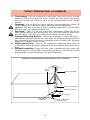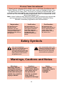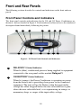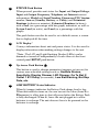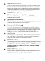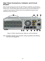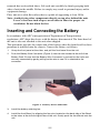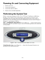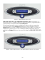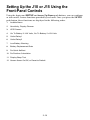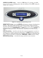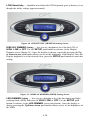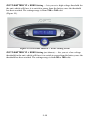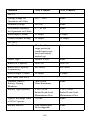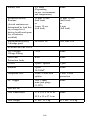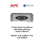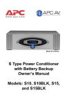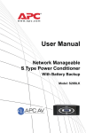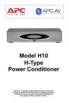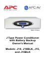
1
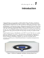
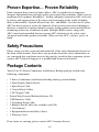
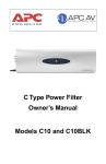
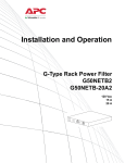
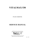
Model J15 Shown
J Type Power Conditioner
with Battery Backup
Owner’s Manual
Models: J10, J10BLK, J15,
and J15BLK
Safety Information
1.
2.
3.
4.
5.
6.
7.
8,
9.
10.
!
11.
12.
13.
14.
15.
Read this manual - Read all of the safety and operating instructions before
installing and operating this device.
Keep this manual - Retain this manual, and all of the safety information that
came with this device.
Warnings - Comply with all warnings presented in this manual, as well as any
found on the device.
Follow Instructions - Follow all operating and use instruction.
Cleaning - Shut off and unplug this device from the wall outlet before
cleaning. Use a soft cloth dampened with mild soap or water only. Do not use
ammonia or alcohol-based cleaning agents.
Note: Any equipment connected to this device will not be powered or protected
from uninterrupted service during this process.
Water and Moisture - Do not use this product near any source of water, or in
an environment where the relative humidity may exceed 95% (noncondensing).
Placement - Do not install this device on any unsteady surface. Do not install
this device on any heat source. Place the unit on a surface capable of supporting
at least 50lbs.
Ventilation - Do not install this device in an area where the vents provided for
cooling purposes may become obstructed.
Power - Ensure this device is connected to a properly grounded AC power
source. Further ensure the device is plugged into a source providing the
required 120 Vac. Do not use a plug adapter which defeats the ground pin of the
AC plug.
Polarization - This device has a polarized AC line plug with two blades and a
ground pin. This plug fits into the wall outlet only in one orientation because of
the ground pin. This is a safety feature. Do not remove the round grounding
pin, or use an adapter that defeats this safety feature.
Power Cord - Ensure power cords are routed in a manner that will preclude
them being pinched, frayed, or stepped on. After connecting other devices to
this device, do not push the rear panel of the device up against any surface (wall
or shelving unit), as this may create an undesired bend in the power cords
which may break the wire strands of the cord.
Antenna Grounding - Although this device provides protection against
electrical surges, when connecting an outside antenna or cable system to
devices connected to this device, ensure the antenna or cable system is
grounded so as to provide additional protection against voltage surges and
static charges in accordance with Section 810 of the National Electric Code,
ANSI/NFPA No.70 (see illustration - next page).
Other Grounding - This device provides a grounding lug at the rear panel for
grounding the device to an external Transient Voltage Surge Suppression
(TVSS) device. Ensure this connection is made in accordance with the
instructions provided by the TVSS device.
Lightning - This device employs Metal Oxide Varisters (MOVs), and other
circuitry to protect against lightning and other sources of voltage surges and
sags. It is not necessary to turn this device or the devices connected to this
device off during a lighting storm.
Power Lines - Do not locate outside antenna systems near overhead power
lines, or other electric light or power circuits, or where it may fall or otherwise
come in contact with these power sources. Do not allow the ladder being used,
or the antenna itself to come into contact with these power sources, as such
contact may be fatal.
i
Safety Information (continued)
16. Overloading - Do not overload the wall outlet where this device is being
connected. Do not overload this device. Ensure the total load to this device
does not exceed that which is listed in the Specifications section of this
manual.
17. Openings - Do not push any object into the vents provided for cooling, as
such an object may come into contact with high-voltage components.
Warning: This may cause injury, death, or damage to the device. Do not allow
liquids to enter any opening in this device.
18. Servicing - There are no user-serviceable components within this device
other than the battery pack. Removal of any cover, other than the front bezel,
from this device may present a shock hazard, and/or void the warranty.
19. Damage Requiring Service - If any type of damage occurs to this device,
immediately disconnect it from the wall outlet. Do not use the Power switch or
line cord into the rear of the device to disconnect power. Notify APC Technical
Support or Customer Service at once.
20. Replacement Parts - There are no components within this device that can
or should be removed/replaced, other than the front display panel and battery
pack.
21. Periodic Inspection - Inspect the line cords, telephone/data line cords, and/
or DSS/Cable TV coaxial cables connected to this device to ensure they remain
fully pushed in or attached and have no apparent damage.
EXAMPLE OF ANTENNA GROUNDING AS PER NATIONAL ELECTRIC CODE (NEC)
Ground
Clamp
Antenna Lead-In Wire
Antenna Discharge Unit
Grounding Conductors
Ground Clamps
Electric Service
Equipment
ii
Power Service Grounding
Electrode System
Protect Your Investment
Thank you for selecting APC's Model J10 or J15 Power Conditioner with
Battery Backup. At APC, we know you have made an intelligent choice sure
to reward you for many years. To ensure you receive all the benefits and
protection which accompany your purchase, please take a few minutes to fill
out and mail the enclosed Warranty Registration Card, or complete the online
form at www.apcav.com.
Note: Under California law, failure to register your purchase may not exclude
you from provisions of the Warranty and Equipment Protection Policy.
Benefits of warranty registration are outlined below.
Registration
Verification
Confirmation
By registering your
purchase now, it
guarantees you will
receive all the information
and special offers you
qualify for as the owner of
this product.
By registering your
purchase now, it confirms
your right to maximum
protection under the
terms and conditions of
the Warranty, and
Equipment Protection
Policy.
By registering your
purchase now, you have a
way to confirm yourself
as the owner of the
product in the event of
fire, theft or loss.
Safety Symbols
This “bolt of lightning”
indicates uninsulated material
within your unit that may
cause an electrical shock. For
the safety of everyone in your
home, please do not remove
the product cover.
!
This “exclamation point” calls
attention to features for which
you should read about in this
Manual to prevent operating
and maintenance problems.
Warnings, Cautions and Notes
Warnings
Warnings provide
information about a
procedure that, if not
performed exactly as
stated, may result in
injury or death.
Cautions
Cautions provide
information about a
procedure that, if
not performed
exactly as stated,
may result in
equipment damage.
iii
Notes
Notes provide
information that is
essential to
highlight.
iv
Table of Contents
Safety Information i
Protect Your Investment iii
Introduction 1-1
Proven Expertise… Proven Reliability 1-2
Safety Precautions 1-2
Package Contents 1-2
Unit Power Capacity 1-3
Features 1-3
Front and Rear Panels 1-5
Installation 2-1
Removing the Battery Pack 2-1
Placing the Unit 2-1
Inserting and Connecting the Battery 2-2
Powering On and Connecting Equipment 2-3
Performing the System Test 2-3
Status and Informational Screens 2-7
Connecting the Components 2-12
Setting Up the J10 or J15 Using the Front-Panel Controls 2-13
Warranty 3-1
Contact Information 4-1
Specifications A-1
Troubleshooting B-1
Unit will not turn on. B-1
Connected equipment reboots or turns off
during or after the unit switches to battery power. B-2
Replace Battery” LED is illuminated. B-3
v
vi
C h a p t e r
1
Introduction
Congratulations on your purchase of APC’s Model J10 or J15 Power Conditioner
with Battery Backup (Model J15 shown in Figure 1). Either unit will protect your
high performance audio and video (AV) system from damaging power surges, spikes
and lightning, as well as power outages. Protection is guaranteed. Isolated noise filter
banks and Automatic Voltage Regulation (AVR) will eliminate power as a source of
audio and video signal degradation. Battery backup power will prevent interruptions,
lost pre-sets, missed DVR recordings and lost media server data when the power goes
out. Data-line surge protection jacks will stop surges traveling over phone or data
lines.
Digital Satellite System, Cable Modem, and CATV Coaxial Cable lines are equally
protected. With APC’s J10 or J15, your entire home entertainment experience is
bullet-proofed from damage or interruption as a result of bad power. With APC’s
Power Conditioner with Battery Backup, you can enjoy your home theater
experience with the peace of mind that performance is optimized and protection
is guaranteed.
Figure 1. J15 Power Conditioner with Battery Backup (Front View)
1-1
Proven Expertise… Proven Reliability
From corporate data centers to home offices, APC is regarded as an innovator,
designer and manufacturer of high-quality power protection solutions. With a proven
reputation for Legendary Reliability , leading companies depend on APC every day
to protect and support many of the most critical networks in the world, including
those at Microsoft®, Toyota® Motor Sales, Inc., and IBM®. Over the last 20 years,
APC has been a pioneer in the development of new power protection technologies
that have resulted in countless industry awards, design patents and an installed-base
numbering in the tens of millions of units. Multiple R&D centers, along with
APC-owned and controlled factories ensure APC solutions are the safest, most
advanced and reliable products available. When you buy APC, you buy “peace of
mind”.
TM
Safety Precautions
Please ensure you have read and understand all of the safety information located at
the front of this manual. If you have any questions about the safety information, or
are concerned that your home may not be properly wired for this equipment, please
contact APC Technical Support or a qualified and licensed electrician.
Package Contents
Your J10 or J15 Power Conditioner with Battery Backup package includes the
following components:
• 1 Power Conditioner with Battery Backup (battery pack included)
• 1 Front Display Panel (Bezel)
• 1 Input Power Cord
• 3 Coaxial Patch Cables
• 1 DC Trigger Cable
• PowerChute Personal Edition Software CD
• USB Interface Cable
• 1 Telephone Patch Cable
• 1 Ethernet Patch Cable (not available with J10)
• 1 User Manual
• 1 Equipment Protection Policy Sheet
• 1 Warranty Card
If any items are missing, please contact APC Customer Service.
1-2
Unit Power Capacity
The J10 Power Conditioner is rated for 600 watts (continuous), and the J15 is rated
for 865 watts (continuous). They have been designed, however, to support component
inrush currents that are much higher than their continuous power rating. The J10 and
J15 are capable of supplying the dynamic peak current draws required by any
component designed to work on a 15 amp circuit. Despite their nameplate power
ratings, high performance AV equipment draw much less than their listed power
ratings. The J10 and J15 can inform the user how much of the power capacity is
available as equipment is connected to the unit.
Features
NOTE: There are no feature differences between the Jxx and JxxBLK models
other than color. Models "J10", "J15" and "JBATT" will be used to describe
both the silver and black models.
The following are major features of the Model J10 and J15.
Battery Backup
Both models provide battery backup power to maintain uninterrupted power for your
home theater in the event of a power blackout. Battery backup power not only
prevents interruptions in your entertainment, it also prevents lost pre-sets, lost
information stored on a Digital Video Recorder (DVR), damaged hard drives, and
premature projector bulb wear and tear.
Automatic Voltage Regulation (AVR)
The J10 and J15 are unique in that they provide AVR, which is engaged to correct
low and high voltage conditions. In doing so, all equipment connected to the J10 or
J15 are protected against these undesired voltage fluctuations, thus prolonging the
life of the equipment. Low voltage conditions can also negatively impact video
quality. AVR, therefore, may help improve picture quality if low voltage conditions
are present.
Surge Protection
The J10 and J15 provide guaranteed protection against damaging surges, spikes and
even lightning. The J Type not only provides protection from surges traveling over
AC power lines, protection is also offered against surges traveling over system data
lines including COAX, telephone and Ethernet lines (varies by model, see
Specifications table). With APC your entire investment in component hardware is
protected.
1-3
Isolated Noise Filter Banks
Both models reduce electromagnetic and radio frequency interference (EMI/RFI)
that, when severe enough, can negatively impact sound and video quality. Each filter
bank is electrically isolated from each other to prevent noise generated by one
component from polluting other connected components. APC's noise filtering can
help enable your system perform to its maximum capabilities.
DC Trigger
When connected to a component acting as a DC trigger, that component controls the
turning on/off, as well as sequencing of the ‘delayed’ outlet banks. The J10 and J15
also allows that DC signal to pass through to another connected component.
Sequenced Turn ON/OFF
This feature ensures that connected equipment is powered-up/down in the proper
order and with the right amount of delay between the stages. It allows the user to
program a delay into the sequence between 0 and 10 seconds. This delay eliminates
transients that can affect connected components or cause the building circuit breaker
to trip.
1-4
Front and Rear Panels
The following sections describe the controls and indicators on the front and rear
panels.
Front Panel Controls and Indicators
The front panel controls and indicators for the J10 and J15 Power Conditioners are
identical, and are detailed in Figure 2. Each numbered callout refers to the numbered
description found immediately following the picture.
1
2
14
3
13
4
12
11
5
10
6
9
7
8
Figure 2. J15 Front Panel Controls and Indicators
1
DELAYED 1 Status Indicator
When lit (blue), conditioned power is being supplied to equipment
connected to the rear-panel outlets marked Delayed 1.
2
ON BATTERY Status Indicator
When lit (orange), the Power Conditioner is operating on power
from the battery and is providing clean power to the connected
equipment. The unit will go On Battery when the input utility
voltage has either dropped below the user-selectable level, gone
above the user-selectable level, or is experiencing an outage, or
momentary drops or surges of the input utility voltage.
1-5
3
STATUS Push Button
When pressed, provides unit status for: Input and Output Voltage,
Input and Output Frequency, Telephone and Internet contact
information, Model and Serial Number, Firmware (FW) Version
number, Source (Standby, Battery, or Utility) and Estimated
Runtime (in hours or minutes), Estimated Runtime (in hours)
with a Fuel (as a percentage with bar graph) indication, as well as
System Load (in watts), and Load (as a percentage with bar
graph).
This push button can also be used to set a default screen, a screen
that is displayed all the time.
4
LCD Display*
Conveys information about unit and power status. It is also used to
display information when making settings changes to the unit.
*Note - The LCD and Light Emitting Diodes (LEDs) can be
dimmed or turned off independently of each other via the front
control panel SETUP push button.
5
Up Arrow Push Button
This button is used to change parameters (increase or turn on) for
various user-selectable settings such as: Audible Alarms,
Sensitivity, Display Dimmer, LED Dimmer, Go To Bat If,
Outlet 1 & 2 Delay (in seconds), Low Bat Warning, Bat Rep
Date, etc.
6
LOW BATTERY Status Indicator
When lit (orange) indicates the Battery Pack charge level is low.
When this indicator turns on, the user can set the value (from 2 to
25 minutes) to allow time to shut off power before the Battery Pack
is fully discharged. When lit, leave the unit plugged in to allow
batteries to recharge. The unit does not have to be powered on for
batteries to recharge.
1-6
7
LINE OK Status Indicator
When lit, input voltage from the utility is within acceptable range.
If not lit, the Automatic Voltage Regulation circuit is correcting
high or low voltage levels to maintain safe voltage conditions for
connected components, or the unit is operating on battery power
due to a blackout or extreme voltage level conditions.
8
FILTERING Status Indicator
When lit, notifies the user that the Electromagnetic
Interference/Radio Frequency Interference (EMI/RFI) noise
reduction circuit is active.
9
OVERLOAD Status Indicator
When lit (red) the unit is overloaded; unplug equipment connected
to the unit until the indicator is no longer lit.
10
Down Arrow Push Button
Is used to change parameters (decrease or turn off) for various
user-selectable settings such as: Audible Alarms, Sensitivity,
Display Dimmer, LED Dimmer, Go To Bat If, Outlet 1 & 2
Delay (in seconds), Low Bat Warning, Bat Rep Date, etc.
11
On/Off Switch
Controls power to all 12 outlets. APC recommends the unit be left
‘on’ at all times. Control power to your system and components
using their own controls as you normally would.
12
SETUP Push Button
This push button is used to advance the display through the various
user-selectable set up functions provided by the unit such as:
Audible Alarms, Sensitivity, Display Dimmer, LED Dimmer, Go
To Bat If, Outlet 1 & 2 Delay (in seconds), Low Bat Warning,
Bat Rep Date, etc.
13
REGULATING Status Indicator
When lit (blue), indicates Automatic Voltage Regulation (AVR) is
engaged to correct low or high voltage conditions.
1-7
14
DELAYED 2 Status Indicator
When lit (blue), conditioned power is being supplied to equipment
connected to the rear-panel outlets marked Delayed 2.
1-8
Rear Panel Connectors, Indicator, and Circuit
Breaker
The rear panel connectors for the J10 and J15 Power Conditioner are detailed in
Figure 3. The only difference between the rear panels of the two models is that the
J15 provides a coaxial cable splitter and jacks for surge-protection of Ethernet
equipment. Each numbered callout refers to the numbered description found
immediately below the picture.
1
12
2
11 10
9
8
7
3
6
4
5
Figure 3. J15 Rear Panel Connectors, Indicator, and Circuit Breaker
Note: All outlets provide surge protection, voltage regulation, noise filtering
and battery backup power.
1-9
1
AC-Powered Outlets - The J10 and J15 Power Conditioner
provides for connection of up to twelve (12) components. The
outlets are arranged according to the type of filtering protection
provided for a given component type. These Isolated Noise Filter
Banks (INFBs) eliminate EMI and RFI that can negatively impact
sound and video quality. APC recommends plugging your devices
into the outlets as marked, in order to assure optimum protection
for your equipment. The outlets are further defined in the
following:
— DIGITAL FILTER Outlets eliminate noise interference for
Digital Components (CD, DVD, DVR, CATV/SAT, Flat Panel
Monitors, Hi-Def tuners, etc.).
Note: Any digital device can be plugged into the DIGITAL
FILTER outlets, any video device can be plugged into either of the
VIDEO FILTER outlets, etc. Example, if you have a cable box and
a satellite receiver, but no monitor, you can plug the cable box into
the "CATV/SAT" outlet, and the satellite receiver into the
"Monitor" outlet.
— VIDEO FILTER Outlets provide filtering for video devices
(TV and VCR).
— ANALOG FILTER Outlets provides filtering for analog-based
equipment (TUNER/AUX and Preamp/Receiver).
— HIGH CURRENT FILTER Outlets provide filtering for
high-current devices (POWERED SUBWOOFER and
AMPLIFIER).
1-10
2
Surge Protected COAX/RF Connectors
The surge protection feature prevents surges traveling over coaxial
data lines from damaging the system. Connect the coaxial cable
from the CATV or Cable Modem provider to the connector marked
“IN”, connect other cables from the connectors marked “OUT” to
the device(s) being protected (CATV box or Cable Modem - in
some cases, the input for both are derived from the single cable
from the provider - such as TV and Internet access through the
same coaxial cable). The J15 model provides a cable splitter for
your CATV system or cable modem. Only the J10 model provides
for connection of a single output.
Additional Surge Protected COAX/RF Connectors
The J10 and J15 also provide surge protection for your satellite,
cable, or RF antenna system. The surge protection feature prevents
surges traveling over a coaxial cable from damaging the
equipment. Connect the coaxial cable from the satellite, cable, or
antenna system to the connector marked “IN”, connect another
coaxial cable from the connector marked “OUT” to the device
being protected (satellite, cable, or antenna).
3
CIRCUIT BREAKER – Provides a “press-to-reset” Circuit
Breaker, which when “tripped” due to an output overload, pops out
and shuts down output power to the outlets. To reset the Circuit
Breaker, push it straight inward.
Caution: When resetting the Circuit Breaker, push the button in
quickly, and release the button. Do not hold the Circuit Breaker
button inward. Failure to comply may result in equipment damage.
4
SYSTEM GROUND Screw
!
Provides for the connection of grounding wires from all of your
equipment to a central terminal screw. This ground connection
eliminates ground loop problems; tie all component grounds to this
terminal to break any possible ground loops that can cause an
audible ‘hum’.
5
BUILDING WIRING FAULT Indicator
!
If lit, then one of three wiring problems exists in the building
wiring circuit: missing ground, overloaded neutral, or reversed
polarity. An electrician should be consulted to resolve the problem.
1-11
6
Input Power Connector
Provides for connection of one end of the supplied AC power cord
to the J10 or J15 Input Power Connector. Connect the other end to
the AC utility power source (15 Amp, 120 Vac, 50-60 Hz).
7
DC TRIGGER Jacks
Provides for connection of a component acting as a DC trigger,
which controls turn on/off, as well as sequencing of the
‘DELAYED1 and 2’ outlet banks. The J10 and J15 also allows
that DC signal to pass through to another connected component.
Caution: When connecting to the DC Trigger jacks, connect the source of
the DC Trigger to the IN jack. The OUT jack should be used
only as a pass-through. The DC Trigger signal can be short
circuited if the input and output cables are reversed. The
maximum input voltage for the DC Trigger is 30VDC. Do not
apply an AC voltage to the DC Trigger jacks. Failure to comply
with this statement may result in equipment damage.
8
ETHERNET Surge Protected Jacks
The J15 protects a device connected to a home network from
surges traveling over Ethernet network data lines. Connect the
supplied RJ45 Cable from the wall jack (source) to the connector
marked “IN”. Connect another network cable from the connector
marked “OUT” to the network equipment to be protected.
9
Surge Protected Telephone Jacks (TEL/DVR/SAT/DSL)
The J15 has a telephone line splitter (2-line 4-wire with splitter)
with surge protection for components connected via telephone line.
Connect the supplied RJ11 Telephone cable from the wall jack
(source) to the telephone line connector marked “IN”. Connect
other telephone cables to the connectors marked “OUT A” and/or
“OUT B” to the equipment to be protected (Telephone, DVR,
DSS, or DSL). The J10 is 1-line 2-wire (no splitter) connector.
NOTE: the splitter serves to split two lines only (two lines running
through one phone cable). It cannot be used to separate a single
line into two.
1-12
10
DATA PORT Jack (USB)
Enables the J10 and J15 to communicate with the included
PowerChute Personal Edition software. If the unit is also protecting
a home computer, the software will automatically save files and
gracefully shutdown the operating system if the J10 or J15 are
about to shutdown due to a low battery condition.
Note: The included PowerChute Personal Edition CD includes
documentation on the installation and use of the software.
11
Cooling Fan
Both units provide a micro-processor controlled, ultra-quiet
cooling fan, which keeps the unit cool when operating on battery
power.
1-13
1-14
C h a p t e r
2
Installation
This chapter contains the following sections:
• Removing the Battery Pack
• Placing the Unit
• Inserting and Connecting the Battery
• Powering On and Connecting Equipment
• Performing the System Test
• Status and Informational Screens
• Connecting the Components
• Setting Up the J10 or J15 Using the Front-Panel Controls
Removing the Battery Pack
1.
Remove the battery retaining bar.
2.
Pull the battery straight back.
CAUTION: Weight distribution within battery pack is uneven. Use both hands to
remove battery.
3.
Push in the retaining tabs to allow the battery to come out completely.
Placing the Unit
Proper placement of the J10 or J15 should be accomplished in accordance with the
following:
Warning: The J10 and J15 weigh approximately 50 pounds each. Two-person lift is
recommended. To ease placement, it is recommended that the battery pack be
2-1
removed first as described above. Lift each unit carefully by firmly grasping both
sides of unit in the middle. Failure to comply may result in personal injury and/or
equipment damage.
Place unit on a solid, flat surface that is capable of supporting at least 50 lbs.
Note: Avoid placing other components directly on top of or behind the unit.
Leave at least one inch of space on all sides to allow for proper air
ventilation. Do not block the fan.
Inserting and Connecting the Battery
In accordance with APC’s interpretation of Department of Transportation
regulations, APC ships this device with the battery disconnected. The front bezel of
the unit is also not attached to the unit when shipped.
This procedure provides for connection of the battery when the front bezel has been
prematurely installed onto the chassis. Connect the battery as follows:
1.
Grasp the front panel at the sides, and pull the front bezel from the unit.
2.
Push the Battery Wire Connector (Figure 4) into the hole located at the left of the
Battery Pack. Ensure that the Battery Wire Connector is pushed into the hole and
securely connected by gently pulling on the wire to see if it is attached to the
connector.
Figure 4. Battery Wire Connection
3.
Install the battery retaining bar.
4.
Install the front Bezel, by aligning the four pins located on the back-side of the Bezel
to the holes at the left and right sides of the unit. Gently push the front Bezel onto the
unit.
2-2
Powering On and Connecting Equipment
1.
Power on the unit.
2.
Connect the equipment.
3.
Connect the data line cables.
4.
Power on the connected equipment.
Performing the System Test
Before connecting equipment to the J10 or J15 Power Conditioner with Battery
Backup, ensure that the unit is functional by connecting the AC Power Cord
(provided) at the rear panel. Press the front panel power switch. Once power is
applied to the unit, the display provides the information screens shown in Figures 7
through 15, and defined as follows:
APC - LEGENDARY RELIABILITY screen (Figure 5) — ensures that the unit is
functional, and to let you know we place our well-earned reputation at the forefront
of this product.
Figure 5. APC - LEGENDARY RELIABILITY Screen
Model Identification screen (Figure 6) — shows that the proper firmware was
installed for the model purchased.
2-3
Figure 6. Model Identification Screen
DELAYED OUTLET1: ON; DELAYED OUTLET2: OFF screen (Figure 7) —
shows that power is available to the device (Tuner or Auxiliary component) that is
connected to the rear-panel outlet marked Delayed 1.
It also shows that power is not yet available to the devices that are connected to
rear-panel outlets marked Delayed 2 (Subwoofer and/or Amplifier). Power to
Delayed 2 devices will be available after the factory preset delay (5 seconds) has
elapsed. See “Setup the J10 or J15” to change the delay period. Once power is
available for Delayed 2 devices, the screen will change to DELAYED OUTLET2:
ON.
Figure 7. DELAYED OUTLET1: ON; DELAYED OUTLET2: OFF Screen
2-4
SELFTEST IS ON; ON-LINE SELFTEST screen (Figure 8) — shows that an
On-Line Selftest is active.
Figure 8. SELFTEST IS ON; ON-LINE SELFTEST Screen
SELFTEST IS ON; ON-BATTERY SELFTEST screen (Figure 9) — shows that
an On-Battery Selftest is active with the unit internally switched to power from
the battery, which should already be connected within the unit. The On Battery
LED is also lit during this test.
Figure 9. SELFTEST IS ON; ON-BATTERY SELFTEST Screen
2-5
SELFTEST RESULT; SELFTEST HAS PASSED screen (Figure 10) — shows
that the Selftest ran successfully to completion. If the message “TEST HAS
FAILED” is displayed, please contact APC Technical Support.
Figure 10. SELFTEST RESULT; SELFTEST HAS PASSED Screen
2-6
Status and Informational Screens
The following sections describe the status and informational screens.
Status Screens
The most important status screens available after the Selftest has completed consist
of:
• INPUT VOLTAGE: XXXV; OUTPUT VOLTAGE: XXXV
• SYSTEM LOAD: <XXXW; LOAD: <XXX%
• EST. RUNTIME: XHRS; FUEL: XXX%
INPUT VOLTAGE: XXXV; OUTPUT VOLTAGE: XXXV
This screen (Figure 11) shows the actual input utility voltage level, as well as the
actual voltage level being output to the connected devices.
Note: As shown in Figure 11, at times, the voltage values on this screen may not
match. This may be due to the fact that separate circuits are used to make
these voltage measurements, and there is a time delay between the two
circuits for updating this status screen. This condition is considered part
of the normal operation of the unit. Also, the voltage values may not
match if the AVR is active.
Figure 11. INPUT VOLTAGE: XXXV; OUTPUT VOLTAGE: XXXV Screen
2-7
SYSTEM LOAD: <XXXW; LOAD: <XXX%
This screen is shown in Figure 12. The J10 and J15 can also display the value (load)
of the connected equipment in watts, as well as a percentage of the total allowable
load connected to the unit. Loads less than 5% of rated load (35 watts for the J10;
45watts for the J15) will be displayed as < 5%.
Figure 12. SYSTEM LOAD: <XXXW; LOAD: <XXX% Screen
EST. RUNTIME: XHRS; FUEL: XXX%
This screen is shown in Figure 13. Each unit can also display the Estimated
Runtime (in hours), as well as the Fuel capacity of the battery (as a percentage)
based on the total load connected to the device. If the estimated runtime is < 1 hour,
the Estimated Runtime will show in minutes.
Figure 13. EST. RUNTIME: XHRS; FUEL: XXX% Screen
Note: For convenience, you can set the unit to display any of the screens as the
“default” screen. The “default” screen is the screen that the system will
revert to once the preset time has expired for other screens being
2-8
displayed. APC recommends you set the “default” screen showing the
“ESTIMATED RUNTIME and FUEL” display (Figure 13).
Informational Screens
The J10 and J15 Power Conditioners with Battery Backup provide the following
informational screens, accessed using the STATUS push button:
• Source: XXXXXXX screen
• FW Version: XXXXXXX screen
• Model Number and Serial Number screen
• Phone Number and Technical Support Internet Address screen
• Input Frequency; Output Frequency screen
SOURCE: XXXXXXX; EST. RUNTIME: XHRS Screen
This screen, shown in Figure 14, shows which source the unit is providing power
from (UTILITY, BATTERY, or STANDBY). It also displays the Estimated
Runtime (in hours) based on the power source and connected equipment load. In
Standby mode, the unit does not provide an output to the rear panel outlets.
Note: Whenever the J10 or J15 is connected to utility power, the electronics
inside of each unit are active. If the front panel Power Switch is turned
off, the unit goes into Standby mode and shuts off power to the
rear-panel outlets.
Figure 14. SOURCE: XXXXXXX; EST. RUNTIME: XHRS Screen
2-9
Firmware Version: XXXXXXX Screen
This screen, shown in Figure 15, provides information about which version of the
firmware is loaded in to the unit. Please have this information available any time you
need to talk with APC Technical Support.
Figure 15. Firmware Version: XXXXXXX Screen
Model Number and Serial Number Screen
This screen, shown in Figure 16, provides information about which Model you have
purchased. It also provides the correct Serial Number for the unit. Please have this
information available any time you need to talk with APC Technical Support, as well.
Figure 16. Model and Serial Number Screen
2-10
Phone Number and Technical Support Internet Address
This screen, shown in Figure 17, provides the world-wide telephone number for
APC, as well as the Internet Web address for APC Technical Support and Customer
Service. Please use this information any time you need to contact APC Technical
Support or Customer Service.
Figure 17. Phone Number and Technical Support Internet Address Screen
2-11
INPUT FREQUENCY; OUTPUT FREQUENCY Screen
This screen, shown in Figure 18, shows the actual input utility voltage frequency, as
well as the actual voltage frequency being output to the connected devices.
Note: At times, the frequency values on this screen may not match, This is due
to the fact that separate circuits are used to make frequency
measurements, and there is a time delay between the two circuits for
updating this status screen. This condition is considered part of the
normal operation of the unit.
Figure 18. INPUT FREQUENCY; OUTPUT FREQUENCY Screen
Connecting the Components
Warning: Do not make telephone, cable, Ethernet, antenna, electrical, or ground
system connections during a lightning storm. Failure to comply may result in
personal injury or death.
Note: Due to the unique filtering and surge protection provided by the J10 and J15,
APC recommends connecting AV components as noted on the rear panel of the unit.
Connect your AV components as noted on the rear panel, and as defined in the
section “REAR PANEL CONNECTORS, INDICATOR, and CIRCUIT BREAKER”. To
ensure ground loops are eliminated, thus eliminating an audible hum through your
speaker system, ground all AV components to the GROUND SYSTEM screw
located on the rear panel of the unit.
2-12
Setting Up the J10 or J15 Using the
Front-Panel Controls
Using the front panel SETUP and Arrow Up/Down push buttons, you can configure
or turn on/off, various functions provided by each unit. Once you press the SETUP
push button, these functions are displayed in the following order:
1.
Audible Alarm
2.
Sensitivity, Display Dimmer
3.
LED Dimmer
4.
Go To Battery If <XX Volts, Go To Battery if >XX Volts
5.
Outlet Delay1
6.
Outlet Delay2
7.
Low Battery Warning
8.
Battery Replacement Date
9.
Do Quick Selftest
10. Do Runtime Calculation
11. Display Beep Test
12. Screen Saver On/Off, or Reset to Default
2-13
AUDIBLE ALARM Setting — when set to ON (Figure 19), provides an audible
tone to alert the user to changing power and unit conditions. In the OFF setting, the
audible tone is silenced.
Figure 19. AUDIBLE ALARM Setting Screen
SENSITIVITY Setting – press the SETUP push button to advance to the Sensitivity
function. This feature adjusts how the J Type reacts to input voltage waveform
distortion and momentary power fluctuations. It allows you to adjust the sensitivity
of the J10 and J15 to LOW, MEDIUM, and HIGH (Figure 20) using the SETUP and
Up/Down Arrow push buttons. The Sensitivity adjustments have the following
value:
HIGH Sensitivity – should be used when the connected equipment is sensitive to
momentary low voltage or brief power fluctuations. In HIGH Sensitivity the unit is
very sensitive to voltage distortion and is, therefore, more likely to switch back and
forth to battery power than it would under a MEDIUM or LOW sensitivity setting.
MEDIUM Sensitivity – is the default setting suitable for most situations.
2-14
LOW Sensitivity — should be used when the UPS frequently goes to battery (even
though the utility voltage appears normal).
Figure 20. SENSITIVITY (MEDIUM) Setting Screen
DISPLAY DIMMER Setting — lets you set a brightness level for the LCD of
HIGH, LOW, or OFF. Use the SETUP push button to advance to the Display
Dimmer screen (Figure 21). Once the display is shown, repeatedly pressing the Up
or Down Arrow push button allows you to set the brightness of the display. Once the
Display brightness is at the desired value, press the SETUP push button to store that
setting.
Figure 21. DISPLAY DIMMER (HIGH) Setting Screen
LED DIMMER Setting — lets you set a brightness level for the front-panel light
emitting diode (LED) indicators of HIGH, LOW, or OFF. Use the SETUP push
button to advance to the LED DIMMER screen (not shown). Once the display is
shown, pressing the Up/Down Arrow push button allows you to set the brightness of
the LEDs.
2-15
GO TO BATTERY IF > XXXV Setting — lets you set a high voltage threshold for
the unit, which will force it to switch to power from the battery once the threshold
has been reached. The settings range is from 134 to 144 volts
(Figure 22).
Figure 22. GO TO BATTERY IF > XXXV Setting Screen
GO TO BATTERY IF < XXXV Setting (not shown) — lets you set a low voltage
threshold for the unit, which will force it to switch to power from the battery once the
threshold has been reached. The settings range is from 90 to 100 volts.
2-16
OUTLET DELAY1 and OUTLET DELAY2 Setting (not shown) screens — lets
you to set a defined time delay (0 to 10 seconds) for when the unit provides power to
the rear panel outlet marked Delayed1 (TUNER/AUX) or Delayed2
(SUBWOOFER and/or AMPLIFIER). By setting this delay (Figure 23), it prevents
power on or power off glitches from effecting other equipment connected to the unit.
Figure 23. Outlet Delay1 Setting Screen (Outlet Delay2 screen not shown)
LOWBATTWARNING: XMIN Setting (Figure 24) — lets you set the unit to sound
an alarm whenever available power from the Battery Pack drops to or below the
setting (2 to 25 minutes).
Figure 24. LOWBATTWARNING Setting Screen
2-17
BATREPDATE: XX/XX/XX Setting (Figure 25) — lets you input the exact date a
replacement Battery Pack was installed in the unit. First, use the Up/Down Arrow
push buttons to set the correct month, then press the SETUP push button to move
the cursor to the day of the month field. Set the day of the month using the Up/Down
Arrow push buttons. Again, press the SETUP push button to move the cursor to the
year field, then set the year using the Up/Down Arrow push buttons.
Figure 25. BATREPDATE: XX/XX/XX Setting Screen
DO QUIK SELFTEST screen (Figure 26) — lets you manually initiate a self-test to
ensure that the battery pack is in good health and that the unit is operating properly.
Note: Once you advance to this screen, press either Up/Down Arrow push buttons to
start the Selftest. During the Selftest, the same screens as previously defined in
this manual, are displayed.
Figure 26. DO QUIK SELFTEST Screen
2-18
DO RUNTIME CAL: screen (Figure 27) — lets you manually initiate a Runtime
Calculation test to calibrate the internal measurements, which should result in
more accurate runtime estimates. This needs to be done once every 6 months, or
when the connected load changes significantly in size. Once initiated, the unit will
operate on battery power until a low battery condition is reached.
Figure 27. DO RUNTIME CAL Screen
DISPLY-BEEP TEST: screen (Figure28) — lets you force the unit to perform
Display and Beep Tests. Simply advance to the DISPLY-BEEP TEST screen and
press either Up/Down Arrow push buttons. This will cause all indicators and display
fields to light (Figure 29), as well as cause an audible beep to sound.
Figure 28. DISPLY-BEEP TEST: Screen
2-19
Figure 29. DISPLY-BEEP TEST: Screen (all indicators/fields lit)
SCREEN SAVER: ON/OFF screen (Figure 30) — lets you force the unit to
alternate a message “J10 (or J15) POWER CONDITIONER WITH BATTERY
BACKUP” continuously between the two lines of fields of the LCD. This feature
helps to maintain display appearance quality, as well as add longevity to the LCD.
Figure 30. SCREEN SAVER Screen
2-20
RESET TO DEFAULT: YES/NO Setting (Figure 31) — lets you force the unit to
reset all previous settings to the factory default values. Simply advance to this
screen, then press either Up/Down Arrow push button. The system will display two
messages of: “INITIALIZING SETUP TO FACTORY DEFAULT” and
“INITIALIZATION COMPLETE”. The system then returns to the RESET TO
DEFAULT screen.
Figure 31. RESET TO DEFAULT Screen
2-21
2-22
C h a p t e r
3
Warranty
Limited Warranty
American Power Conversion (APC) warrants its products to be free from defects in
materials and workmanship for a period of two years from the date of purchase. Its
obligation under this warranty is limited to repairing or replacing, at its own sole
option, any such defective products. To obtain service under warranty you must first
obtain a Returned Material Authorization (RMA) number from customer support.
Products must be returned with the following:
• Prepaid transportation charges
• Brief description of the problem encountered
• Proof of date and place of purchase
This warranty does not apply to equipment that has been damaged by accident,
negligence, or misapplication or has been altered or modified in any way. This
warranty applies only to the original purchaser who must have properly registered the
product within 10 days of purchase.
EXCEPT AS PROVIDED HEREIN, AMERICAN POWER CONVERSION
MAKES NO WARRANTIES, EXPRESSED OR IMPLIED, INCLUDING
WARRANTIES OF MERCHANTABILITY AND FITNESS FOR A PARTICULAR
PURPOSE. Some states do not permit limitation or exclusion of implied warranties;
therefore, the aforesaid limitation(s) or exclusion(s) may not apply to the purchaser.
3-1
EXCEPT AS PROVIDED ABOVE, IN NO EVENT WILL APC BE LIABLE FOR
DIRECT, INDIRECT, SPECIAL, INCIDENTAL, OR CONSEQUENTIAL
DAMAGES ARISING OUT OF THE USE OF THIS PRODUCT, EVEN IF
ADVISED OF THE POSSIBILTY OF SUCH DAMAGE. Specifically APC is not
liable for any costs, such as lost profits or revenue, loss of equipment, loss of use of
equipment, loss of software, loss of data, costs of substitutes, claims by third parties,
or otherwise.
Note: For information regarding APC’s Lifetime Equipment Protection Policy,
please see the enclosed Equipment Protection Policy Sheet.
3-2
C h a p t e r
4
Contact Information
Technical Support
Internet
Address:
http://www.apc.com/support
Email
Support:
support.apcc.com
Toll free:
(888) 88-APCAV
General Information
Address:
American Power Conversion
132 Fairgrounds Rd.
West Kingston, RI 02892 USA
Toll free
(U.S. and
Canada):
(800) 800-4272
Fax:
(401) 789-3710
4-1
4-2
S p e c i fi c a t i o n s
A
Technical Specifications
The table on the following pages contains the technical specifications for the Model
J15 and J10 J Type Power Conditioner with Battery Backup.
Federal Communications Commission (FCC) Compliance
Information
This device complies with Part 68 and Part 15 of the FCC rules. Operation is subject
to the following two conditions: (1) This device must not cause harmful interference,
and (2) This device must accept any interference received, including interference that
may cause undesired operation.
As required, the bottom of this equipment contains, among other information, the
Registration Number and Ringer Equivalence Number (REN) for this equipment. If
requested, this information must be provided to the telephone company.
A-1
Models
J15, J15BLK
J10, J10BLK
Voltage Range for
Operation on Utility
90V – 144V
Same
Nominal Voltage
120 Vac
Same
Allowable Frequency
for Operation on Utility
47 – 63 Hz
Same
Rated Input Current
12 Amps
9 Amps
Circuit Breaker Rating
15 Amps
15 Amps
# of Outlets
12 (all outlets are
surge protected,
conditioned, regulated and battery
backed up)
Same
Outlet Type
NEMA 5-15R
Same
Rated VA Capacity
1440 VA
1000 VA
Rated Watt Capacity
(continuous)
865 Watts
600 Watts
Rated Output Current
12 Amps
9 Amps
Transfer Time to
Battery During
Blackout
7ms typical,
10ms maximum
Same
Battery Type/Quantity
2 12V/9A hr
Sealed Lead-Acid,
Maintenance Free
2 12V/7A hr
Sealed Lead-Acid,
Maintenance Free
Typical Recharge Time
to 90% Capacity
<16 hrs
Same
Battery Service
User-replaceable,
Hot-swappable
Same
INPUT
OUTPUT
BATTERY BACKUP
A-2
Battery Life
2-5 Years
(Depending
on use, environment,
and temperature)
Same
Estimated Battery
Runtime
13 min. 30 sec.
(half load)
or
3 min. 30 sec.
(full load)
13 min. 30 sec.
(half load)
or
4 min.
(full load)
APCRBC107
APCRBC108
Let-Through
Voltage Rating
<85V
Same
Data Line
Protection Jacks
RJ45
Same
COAX
3 pair + splitter
3 pair
Ethernet
1 pair
10/100bT
None
Telephone/DSL
2 line, 4 wire with
splitter
1 line, 2 wire
protection
DC Trigger
Two 3.5mm
mini-jack plugs
(5-30V)
Same
17 x 5.25 x 18.55 in.
Same
(Actual runtimes are
determined by load, battery charge level,
battery health and quantity of batteries
installed)
Replacement Battery
Cartridge part#
SURGE PROTECTION
PHYSICAL
Unit Dimensions
43.2 x 13 x 47.1 cm
Unit Weight
47 lbs / 21.3 kg
A-3
43.3 lbs / 19.6 kg
WARRANTY
Warranty
2 years
including
battery
A-4
Same
T r o u b l e s h o o t i n g
B
Troubleshooting Problems
This appendix describes possible causes and solutions for the following problems:
1.
Unit will not turn on.
2.
Connected equipment reboots or turns off during or after the unit switches to battery power.
3.
“Replace Battery” LED is indicated.
Note: The LCD screen will display any faults or warning conditions that occur
along with a message explaining what action to take. If ever in doubt as to
what action to take, please contact APC Technical Support (Internet—
www.apc.com/support, Phone — 888-88-APCAV).
Unit will not turn on.
Possible Cause: Battery is not connected
Solution: Remove front display panel by grasping the sides and pulling straight
back. Battery is located on the right side of the unit. The black battery connector
should be pushed snugly into the battery socket located just to the left of the battery
pack. See “Connect Battery” to view photographs of this procedure.
Possible Cause: Input power cord is not connected properly.
Solution: Ensure supplied power cord is connected firmly on both ends.
Possible Cause: No power or insufficient power available at the wall outlet.
Solution: Ensure the wall outlet has good power by using a voltmeter or by plugging
in another device.
Note: The unit will not turn on and accept incoming utility power if the power is
out of range. The unit can still be “cold-started” using battery power, by
pressing and holding the power switch until the unit beeps.
B-1
Possible Cause: No power or insufficient power available at the wall outlet.
Solution: Ensure the wall outlet has good power by using a voltmeter or by plugging
in another device.
Note: The unit will not turn on and accept incoming utility power if the power is
out of range. The unit can still be “cold-started” using battery power, by
pressing and holding the power switch until the unit beeps.
Possible Cause: Circuit Breaker has tripped.
Solution: Check both home and unit circuit breakers. If the circuit breaker located on
the rear of the APC unit has tripped, the center post will be extended outwards about
1/4 to 1/2 inch. Push it back in to reset it. If the trip occurs again, reduce the amount
of equipment that is plugged into the unit and try again. While the unit circuit
breaker is rated for 15 Amps, the National Electric Code (NEC) dictates that any
particular home circuit should not be loaded to more than 80% of its rating.
Connected equipment reboots or turns off during
or after the unit switches to battery power.
Possible Cause: Battery was disconnected after unit had been installed and powered
on.
Solution: The unit will warn users through the front display if the battery is
disconnected, but this warning could go unnoticed. Remove the front bezel by
grasping the sides and pulling straight back. Check the battery connection to make
sure that it is firmly pushed into its battery connector socket.
Possible Cause: Unit is overloaded.
Solution: If the unit has too much equipment plugged into the outlets, the runtime on
battery will become very short. Using the front display, you can see how much of the
UPS load capacity is used. Additionally, there is an “Overload” LED on the front
panel which will light ‘red’ if the unit is overloaded. If the unit is near overload or
overloaded, it is recommended the load be reduced by unplugging one or more
components.
Possible Cause: Battery charge level was low at the time the unit switched to battery
power.
Solution: Allow the unit to fully recharge, by leaving the unit plugged in. It takes
approximately 16 hours to recharge a discharged battery to 90% capacity.
Possible Cause: If the above problem remains unsolved….
Solution: Contact APC Technical Support at 888-88APCAV or go to
www.apcav.com.
B-2
“Replace Battery” LED is indicated.
Possible Cause: Battery is nearing the end of its useful life.
Solution: If the unit’s warranty is more than 2 years from date of purchase, a
Replacement Battery Cartridge (see part#s above in tech spec table) can be ordered
from your AV dealer.
Address:
American Power Conversion
132 Fairgrounds Rd.
West Kingston, RI 02892 USA
Email Support:
support.apcc.com
APC Toll-Free
Technical Support:
888-88APCAV
B-3
990-2457 Copyright © 2005 American Power Conversion
All rights reserved. The APC AV logo is a registered trademark
of American Power Conversion. All other trademarks are
the property of their respective owners.
B-4