1
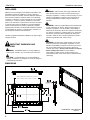
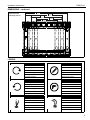
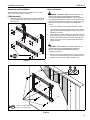
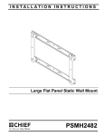
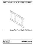
INSTALLATION INSTRUCTIONS
Large Flat Panel Static Wall Mount
Spanish Product Description
German Product Description
Portuguese Product Description
Italian Product Description
Dutch Product Description
French Product Description
PSMH2744
PSMH2744
Installation Instructions
DISCLAIMER
WARNING: Failure to read, thoroughly understand, and
Milestone AV Technologies and its affiliated corporations and
subsidiaries (collectively "Milestone"), intend to make this
manual accurate and complete. However, Milestone makes no
claim that the information contained herein covers all details,
conditions or variations, nor does it provide for every possible
contingency in connection with the installation or use of this
product. The information contained in this document is subject
to change without notice or obligation of any kind. Milestone
makes no representation of warranty, expressed or implied,
regarding the information contained herein. Milestone assumes
no responsibility for accuracy, completeness or sufficiency of
the information contained in this document.
follow all instructions can result in serious personal injury,
damage to equipment, or voiding of factory warranty! It is the
installer’s responsibility to make sure all components are
properly assembled and installed using the instructions
provided.
WARNING: Failure to provide adequate structural strength
for this component can result in serious personal injury or
damage to equipment! It is the installer’s responsibility to
make sure the structure to which this component is attached
can support a minimum of 1,200 lbs (544.31 kg). Reinforce
the structure as required before installing the component.
The wall to which the mount is being attached may have a
maximum drywall thickness of 5/8" (1.6cm).
Chief® is a registered trademark of Milestone AV Technologies.
All rights reserved.
WARNING: Exceeding the weight capacity can result in
serious personal injury or damage to equipment! It is the
installer’s responsibility to make sure the structure to which
this mount is being attached can support a minimum of
1,200 lbs (544.31 kg). Reinforce the structure as required
before installing this mount. It is the installer’s
responsibility to make sure the combined weight of all
components located on the mount does not exceed 300 lbs
(136.08 kg).
IMPORTANT WARNINGS AND
CAUTIONS!
WARNING: A WARNING alerts you to the possibility of
serious injury or death if you do not follow the instructions.
CAUTION: A CAUTION alerts you to the possibility of
damage or destruction of equipment if you do not follow the
corresponding instructions.
DIMENSIONS
VERTICAL BRACKETS CAN BE SET TO A WIDTH OF
800mm, 700mm, 600mm, 500mm, or 400mm
318mm
12.50in
200mm
7.87in
635mm
25.00in
400mm
15.75in
73mm
2.88in
18.19in
924mm
36.38in
2
DIMENSIONS: [MILLIMETERS]
INCHES
Installation Instructions
PSMH2744
DIMENSIONS -- continued
800mm
31.50in
Vertical bracket
mounting choices
600mm
23.62in
400mm
15.75in
700mm
27.56in
500mm
19.69in
LEGEND
Tighten Fastener
Pencil Mark
Apretar elemento de fijación
Marcar con lápiz
Befestigungsteil festziehen
Stiftmarkierung
Apertar fixador
Marcar com lápis
Serrare il fissaggio
Segno a matita
Bevestiging vastdraaien
Potloodmerkteken
Serrez les fixations
Marquage au crayon
Loosen Fastener
Drill Hole
Aflojar elemento de fijación
Perforar
Befestigungsteil lösen
Bohrloch
Desapertar fixador
Fazer furo
Allentare il fissaggio
Praticare un foro
Bevestiging losdraaien
Gat boren
Desserrez les fixations
Percez un trou
Phillips Screwdriver
Hex-Head Wrench
Destornillador Phillips
Llave de cabeza hexagonal
Kreuzschlitzschraubendreher
Sechskantschlüssel
Chave de fendas Phillips
Chave de cabeça sextavada
Cacciavite a stella
Chiave esagonale
Kruiskopschroevendraaier
Zeskantsleutel
Tournevis à pointe cruciforme
Clé à tête hexagonale
3
PSMH2744
Installation Instructions
TOOLS REQUIRED FOR INSTALLATION
M5 (included)
5/32" (included)
7/32" (5.5mm)
#2
PARTS
B (2)
[Vertical bracket]
A (2)
[Horizontal bracket]
C (4)
[Mounting button]
D (1)
[3/16" hex bit]
E (4)
1/4-20 x 1 1/8"
F (16)
M8 x 16mm
H (1)
M5
G (1)
5/32"
K (8)
5/16"
J (8)
5/16 x 2-1/2"
4
Installation Instructions
PSMH2744
Assembly and Installation
Mount Installation
The PSMH2840 is designed to be installed on 2" x 4" wood
studs, 16" on-center or 24" on-center.
WARNING: IMPROPER INSTALLATION CAN LEAD TO
PSMH Assembly
1.
DISPLAY FALLING CAUSING SERIOUS PERSONAL
INJURY OR DAMAGE TO EQUIPMENT! It is the installer’s
responsibility to make sure the structure to which this mount is
being attached can support a minimum of 1,200 lbs (544.3 kg).
Reinforce the structure as required before installing this
mount.
Attach two vertical brackets (B) to two horizontal brackets
(A) using sixteen M8 x 16mm button head cap screws (F).
(See Figure 1)
1.
Place mount against wall in desired installation location.
2.
Level and adjust horizontal position making certain slots in
upper and lower horizontal brackets on mount are properly
positioned over studs.
3.
Using a pencil, or similar marking tool, mark the location of
six mounting holes (or four mounting holes for 24" on-center
studs) in horizontal brackets onto surface. (See Figure 2)
4.
Drill six 7/32" (four for 24" on-center studs) pilot holes at
marked locations.
CAUTION: IMPROPER INSTALLATION CAN LEAD TO
MOUNT FALLING CAUSING SERIOUS PERSONAL
INJURY OR DAMAGE TO EQUIPMENT! DO NOT
overtighten hardware!
1
5.
(F) x 16
Secure mount to studs using six 5/16 x 2-1/2" lag screws (J)
and six 5/16" (K) flat washers [or four lag screws and four
washers for 24" on-center studs]. (See Figure 2)
Figure 1
3
5
4
x 6 (16" on-center studs)
x 4 (24" on-center studs)
Figure 2
5
PSMH2744
Installation Instructions
Display Installation
WARNING: IMPROPER INSTALLATION CAN LEAD TO
5.
Move display forward until recessed area of mounting
buttons is positioned over lower area of teardrop mounting
holes. (See Figure 5)
6.
Lower display until recess area of mounting buttons is
seated in lower area of teardrop mounting holes.
(See Figure 5)
MOUNT FALLING CAUSING SERIOUS PERSONAL
INJURY OR DAMAGE TO EQUIPMENT! DO NOT substitute
hardware.
1.
Move Q-Latches on mount to the OPEN position.
(See Figure 3)
5
6
1
OPEN
4
Q-Latch
Figure 3
2.
Install four mounting buttons (C) onto display using 1/4-20 x
1 1/8" socket head screws (E). (See Figure 4)
Figure 5
7.
(C) x 4
Move Q-Latches to Closed position and lock if desired.
(See Figure 6)
Optional padlock
added here
CLOSED
7
2
Q-Latch
(E) x 4
Figure 6
Figure 4
3.
Lift display following lifting instructions provided by display
manufacturer.
4.
Align mounting buttons on display with teardrop mounting
holes in mount. (See Figure 5)
6
8.
Route wires and cables to display.
Installation Instructions
PSMH2744
7
PSMH2744
Installation Instructions
USA/International
Europe
Chief Manufacturing, a products division
of Milestone AV Technologies
8800-002071 Rev00
2011 Milestone AV Technologies, a
Duchossois Group Company
www.chiefmfg.com
01/11
Asia Pacific
A
P
F
A
P
F
A
8401 Eagle Creek Parkway, Savage, MN 55378
800.582.6480 / 952.894.6280
877.894.6918 / 952.894.6918
Fellenoord 130 5611 ZB EINDHOVEN, The Netherlands
+31 (0)40 2668620
+31 (0)40 2668615
Office No. 1 on 12/F, Shatin Galleria
18-24 Shan Mei Street
Fotan, Shatin, Hong Kong
P 852 2145 4099
F 852 2145 4477