1
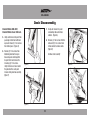
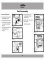
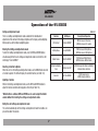
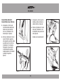
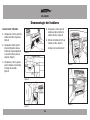
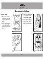
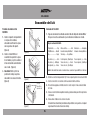
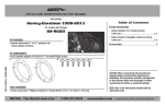
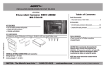
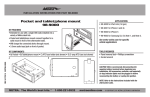
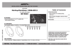
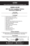
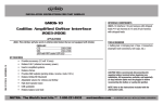
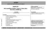
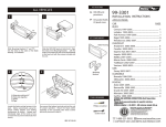
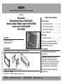
INSTALLATION INSTRUCTIONS FOR PART 95-3303B
APPLICATIONS
REV. 12/16/2013 INST95-3303B
Chevrolet:
Malibu/Malibu Maxx 2004-2007,
Malibu Classic 2008, Cobalt* 2005-2006
Pontiac G6** 2005-2009
95-3303B
Table of Contents
Dash Disassembly
– Chevrolet Malibu 2004-2007.............................2-3
– Chevrolet Malibu Classic 2008 ..........................2-3
– Chevrolet Cobalt** 2005-2006 ............................. 4
– Pontiac G6* 2006-2009 ....................................... 5
Kit Assembly
KIT FEATURES
• Double DIN radio provision
• Painted matte black
– Double DIN radio provision ................................6-7
KIT COMPONENTS
• A) Radio Housing • B) Brackets • C) Display Pod • D) Harness (not shown)
TOOLS REQUIRED
• Panel removal tool • Phillips screwdriver
• Socket Wrench
A
B
*This kit is only needed for OnStar retention.
**In 2009, only use this kit for models where the
5th digit of the VIN is a G, H or M.
C
CAUTION: Metra recommends disconnecting the
negative battery terminal before beginning any
installation. All accessories, switches, and especially
air bag indicator lights must be plugged in before
reconnecting the battery or cycling the ignition.
WIRING & ANTENNA CONNECTIONS (sold separately)
Wiring Harness: • Included
Antenna Adapter: • 40-GM10 - GM antenna adapter 1988-up
METRA. The World’s best kits.™
1-800-221-0932
NOTE: Refer to the instructions included with the
aftermarket radio.
metraonline.com
© COPYRIGHT 2013 METRA ELECTRONICS CORPORATION
95-3303B
Dash Disassembly
Chevrolet Malibu 2004-2007,
Chevrolet Malibu Classic 2008
3. Remove (2) 7 mm screws from
bottom edge of panel below
steering wheel. Unclip panel and
let hang. It is not necessary to
completely remove panel.
(Figure C)
1. Unclip and remove wood grain/
painted trim pieces from both
sides of steering wheel. (Figure A)
2. Unclip and remove side panel
from driver’s side of dash with
door open and remove (2) 7 mm
screws. (Figure B)
4. Unclip and remove wood grain/
painted trim pieces from above
glove box. (Figure D)
Continued on next page
(Figure A)
(Figure C)
(Figure B)
(Figure D)
2
95-3303B
Dash Disassembly
Chevrolet Malibu 2004-2007,
Chevrolet Malibu Classic 2008 cont.
7. Unclip and remove trim panel
surrounding radio and climate
controls. (Figure G)
5. Unclip and remove side panel from
passenger side of dash with door
open and remove (2) 7 mm screws
from behind panel. (Figure E)
6. Remove (2) 7 mm screws from
bottom of glove box then open
box and squeeze sides together
to open further and remove the
remaining (4) 7 mm screws.
Unclip the black vent cover under
the glove box then unclip and
remove entire glove box assembly.
(Figure F)
8. Remove (4) 7 mm screws from the
radio and (2) 7 mm screws from
climate control to remove radio.
(Figure H)
Continue to kit assembly
(Figure E)
(Figure G)
(Figure F)
(Figure H)
3
95-3303B
Dash Disassembly
4. Unclip and remove trim panel
surrounding radio and climate
controls. (Figure D)
Chevrolet Cobalt* 2005-2006
1. Unclip and remove trim panel from
above glove box. (Figure A)
2. Unclip upper edge of panel below
steering column and let hang. Not
necessary to remove completely.
(Figure B)
5. Remove (4) 9/32” screws securing
radio. (Figure E)
Continue to kit assembly
(Figure A)
3. Unclip and remove small trim panel
to right of ignition switch.
(Figure C)
(Figure D)
(Figure B)
(Figure E)
(Figure C)
4
95-3303B
Dash Disassembly
3. Unclip and remove center panel
surrounding radio and A/C controls.
(Figure C)
Pontiac G6** 2005-2009
1. Open glove box and remove (6)
screws from outer edge then
unclip and remove box. (Figure A)
4. Remove (4) screws and extract
radio from sub dash. (Figure D)
2. Remove (4) screws from panel
below steering column and unclip
and remove panel. (Figure B)
Continue to kit assembly
Top View
(Figure A)
(Figure C)
(Figure B)
(Figure D)
5
95-3303B
Kit Assembly
ISO DDIN radio provision
Wiring the 95-3303B
1. Slide the appropriate bracket into
the trim plate aligning the holes in
the trim plate to the clips on the
bracket. (Figure A)
1. Make wiring connections using the Metra/EIA Wiring Code chart, shown below,
and the instructions included with the radio.
2. Slide the DDIN radio into the trim
plate bracket assembly and secure
the unit to the kit using the screws
supplied with the radio. (Figure B)
Metra/EIA Wiring Code
(Figure A)
3. Cobalt only: Cut and remove top
mounting tabs on each side of the
radio housing. (Figure C)
12V Ignition/Acc........... Red
12V Batt/Memory..... Yellow
Ground ......................Black
Power Antenna ........... Blue
Amp Turn-On ... Blue/White*
Amp Ground ....Black/White
Illumination ............. Orange
Dimmer ........ Orange/White
Right Front (+) ............ Gray
Right Front (-) ....Gray/Black
Left Front (+) .............White
Left Front (-) ....White/Black
Right Rear (+) ............Violet
Right Rear (-) ... Violet/Black
Left Rear (+) ............. Green
Left Rear (-) .... Green/Black
*Note: Blue/White wire must be connected even if there isn’t an AMP in the vehicle.
2. Plug the clear 10-way and 12-way connectors into the back of the 95-3303 housing.
3. Connect the Light Blue 24-way connector to the factory 24-way harness.
4. On vehicles equipped with OnStar, connect the Black 12-way connector to the
factory 12-way harness.
5. Re-connect the negative battery terminal and test the unit for proper operation.
6. Reassemble dash in reverse order of disassembly.
The included module is intended for mounting under-dash, in the glove box,
or any desired location. It does not need to be accessed all the time.
(Figure B)
Cut the two
top holes off
(Figure C)
6
95-3303B
Operation of the 95-3303B
Setting and Adjustment mode
There is a Settings and Adjustments mode available for the individualized
adjustment of the contrast of the display, brightness of the display and backlighting,
OnStar volume, and the button backlighting color.
Table 1.0
Function
Entering the Settings and Adjustments mode
To enter the Settings and Adjustments mode, press the INFO and MENU buttons
simultaneously. When the unit settings and adjustments mode is entered, the LCD
will display “Func Sel MENU.”
Selecting a Function to Update
When the unit is in the Settings and Adjustment mode, use the MENU button to select
a function to update. The LCD will display the selected function (see Table 1.0).
Updating a function
While in the Settings and Adjustment mode, use the INFO and ENTER buttons to
adjust the function selected and displayed on the LCD (see Table 1.0).
*When OnStar is activated, INFO and ENTER can be used to adjust the OnStar
volume without first entering the settings and adjustments mode.
Exiting the unit settings and adjustments mode
The unit will automatically exit the settings and adjustments mode if no buttons are
pressed for about 10-seconds.
7
LCD Display
Description of Operation
LCD Contrast
Contrast INF/ENT
INFO increases LCD contrast
ENTER decreases LCD contrast
LCD Brightness
Bright INF/ENT
INFO increases LCD brightness
ENTER decreases LCD brightness
OnStar Volume
OnSt Vol INF/ENT
INFO increases OnStar Volume
ENTER decreases OnStar Volume
Button Backlighting
Color
Button Color ENT
ENTER changes the button backlighting
between Amber and Green
Clock Set
Set Time INF/ENT
INFO changes hour(s)
ENTER changes minute(s)
INSTALLATION INSTRUCTIONS FOR PART 95-3303B
KNOWLEDGE IS POWER
REV. 12/16/2013 INST95-3303B
Enhance your installation and fabrication skills by
enrolling in the most recognized and respected
mobile electronics school in our industry.
Log onto www.installerinstitute.com or call
800-354-6782 for more information and take steps
toward a better tomorrow.
Metra recommends MECP
certified technicians
METRA. The World’s best kits.™
1-800-221-0932
metraonline.com
© COPYRIGHT 2013 METRA ELECTRONICS CORPORATION
INSTRUCCIONES DE INSTALACIÓN PARA LA PIEZA 95-3303B
AplicAciones
REV. 12/16/2013 INST95-3303B
Chevrolet:
Malibu/Malibu Maxx 2004-2007,
Malibu Classic 2008, Cobalt* 2005-2006
Pontiac G6** 2005-2009
95-3303B
Indice
Desmontaje del tablero
– Chevrolet Malibu 2004-2007.............................2-3
– Chevrolet Malibu Classic 2008 ..........................2-3
– Chevrolet Cobalt** 2005-2006 ............................. 4
– Pontiac G6* 2006-2009 ....................................... 5
Ensamble del kit
cArActerísticAs del kit
• Provisión de radio doble DIN
• Pintura negro mate
– Provisión de radio doble DIN...............................6-7
componentes del kit
• A) Carcasa del radio • B) Soportes • C) Base de pantalla • D) Arnés (no se muestra)
HerrAmientAs requeridAs
• Herramienta para quitar paneles
• Destornillador Phillips • Llave para dados
A
B
*Este kit únicamente se necesita para retener OnStar.
**En 2009, utilice únicamente este kit para los modelos
donde el 5° dígito del VIN es una G, H o M.
C
PRECAUCIÓN: Metra recomienda desconectar el terminal
negativo de la batería antes de comenzar cualquier
instalación. Todos los accesorios, interruptores y,
especialmente, las luces indicadoras de airbag deben
estar enchufados antes de volver a conectar la batería o
comenzar el ciclo de ignición.
cABleAdo Y coneXiones de AntenA (se venden por separado)
Arnés de cableado: • INCLUIDO
Adaptador de antena: • 40-GM10 - Adaptador de antena GM 1988 y más recientes
METRA. The World’s best kits.™
1-800-221-0932
Nota: Remítase a las instrucciones incluidas con el radio
de posventa.
metraonline.com
© COPYRIGHT 2013 METRA ELECTRONICS CORPORATION
95-3303B
Desmontaje del tablero
3. Retire los (2) tornillos de 7 mm del
borde inferior del panel debajo del
volante. Desenganche el panel y
déjelo colgando. No es necesario
retirar el panel por completo.
(Figura C)
Chevrolet Malibu 2004-2007,
Chevrolet Malibu Classic 2008
1. Desenganche y retire las piezas
de moldura de veta de madera/
pintadas de ambos lados del
volante. (Figura A)
2. Desenganche y retire el panel
lateral del lado del conductor del
tablero con la puerta abierta y
retire los (2) tornillos de 7 mm.
(Figura B)
4. Desenganche y retire las piezas
de moldura de veta de madera/
pintadas de arriba de la guantera.
(Figura D)
Continúa en la siguiente página.
(Figura A)
(Figura B)
(Figura C)
(Figura D)
2
95-3303B
Chevrolet Malibu 2004-2007,
Chevrolet Malibu Classic 2008 cont.
7. Desenganche y retire el panel de
moldura que rodea el radio y los
controles del clima. (Figura G)
5. Desenganche y retire el panel
lateral del lado del conductor del
tablero con la puerta abierta y
retire los (2) tornillos de 7 mm
detrás del panel. (Figura E)
6. Retire los (2) tornillos de 7 mm de
la parte inferior de la guantera,
abra la guantera y apriete los lados
para abrirla aún más y retire los
(4) tornillos de 7 mm restantes.
Desenganche la tapa negra de
la rejilla debajo de la guantera,
luego desenganche y retire todo el
ensamble de la guantera.
(Figura F)
8. Retire los (4) tornillos de 7 mm del
radio y los (2) tornillos de 7 mm
del control del clima para retirar el
radio. (Figura H)
Continúe con el ensamble del kit.
(Figura E)
(Figura G)
(Figura F)
(Figura H)
3
95-3303B
Desmontaje del tablero
4. Desenganche y retire el panel de
moldura que rodea el radio y los
controles del clima. (Figura D)
Chevrolet Cobalt* 2005-2006
1. Desenganche y retire el panel de la
moldura de arriba de la guantera.
(Figura A)
2. Desenganche el borde superior
del panel debajo de la columna
de dirección y déjelo colgando. No
es necesario retirar el panel por
completo. (Figura B)
5. Retire los (4) tornillos de 9/32” que
sostienen el radio. (Figura E)
Continúe con el ensamble del kit.
(Figura A)
3. Desenganche y retire el pequeño
panel de moldura a la derecha del
interruptor de encendido.
(Figura C)
(Figura D)
(Figura B)
(Figura E)
(Figura C)
4
95-3303B
Desmontaje del tablero
3. Suelte y retire el panel central que
rodea el radio y los controles del
aire acondicionado. (Figura C)
Pontiac G6** 2005-2009
1. Abra la guantera y retire los (6)
tornillos del borde exterior, luego
desenganche y retire la guantera.
(Figura A)
4. Quite los (4) tornillos y extraiga el
radio del sub tablero. (Figura D)
2. Retire los (4) tornillos del panel
debajo de la columna de dirección
y desenganche y retire el panel.
(Figura B)
Continúe con el ensamble del kit.
vista desde arriba
(Figura A)
(Figura C)
(Figura B)
(Figura D)
5
95-3303B
Ensamble del kit
Provisión de unidad central
ISO DDIN.
1. Deslice el soporte correspondiente
en la placa de la moldura,
alineando los orificios de la placa
con los ganchos del soporte.
(Figura A)
2. Deslice el radio DDIN en el
ensamble del soporte de la placa
de la moldura y sujete la unidad al
kit con los tornillos suministrados
con el radio. (Figura B)
3. Solo Cobalt: Corte y retire las
pestañas de montaje superior a
cada lado de la carcasa del radio.
(Figura C)
Cableado del 95-3303B
1. Haga las conexiones de cableado usando la tabla de código de cableado Metra/
EIA que se muestra a continuación y las instrucciones incluidas con el radio.
Código de cableado Metra/EIA
(Figura A)
12V Ignición/Acc ............... Rojo
12V Bat/Memoria ........ Amarillo
Tierra...............................Negro
Antena eléctrica ................ Azul
Encendido de amp.Azul/Blanco*
Tierra amp...........Negro/Blanco
Iluminación............. Anaranjado
Atenuador....Anaranjado/Blanco
Frente derecho (+) ............Gris
Frente derecho (-)... Gris/Negro
Frente izquierdo (+) ...... Blanco
Frente izquierdo (-)Blanco/Negro
Trasero derecho (+) .......Violeta
Trasero derecho (-)Violeta/Negro
Trasero izquierdo (+) ...... Verde
Trasero izquierdo (-)Verde/Negro
*Nota: El cable azul/blanco debe conectarse incluso cuando no haya un AMP en el vehículo.
2. Enchufe los conectores transparentes de 10 y 12 vías en la parte posterior de la carcasa 95-3303.
3. Conecte el conector de color azul claro de 24 vías al arnés de fábrica de 24 vías.
4. En los vehículos equipados con OnStar, conecte el conector negro de 12 vías al arnés de fábrica
de 12 vías.
5. Vuelva a conectar la terminal negativa de la batería y pruebe la unidad para verificar que funcione
correctamente.
6. Vuelva a armar el tablero al revés de como lo desarmó.
El módulo incluido está diseñado para instalarse debajo del tablero, en la guantera o en cualquier
lugar deseado. No necesita accesarse todo el tiempo.
(Figura B)
corte los
dos orificios
superiores de
(Figura C)
6
95-3303B
Operación del 95-3303B
Modo de configuración y ajustes
Hay un modo de configuración y ajustes disponible, asequible para el ajuste
individualizado del contraste, brillo y retroiluminación de la pantalla, volumen de
OnStar y el color de retroiluminación de los botones.
Tabla 1.0
Cómo entrar al modo de configuración y ajustes
Para entrar al modo de configuración y ajustes, presione al mismo tiempo los
botones INFO y MENU. Al entrar al modo de configuración y ajustes, la pantalla LCD
mostrará “Func Sel MENU”.
Cómo seleccionar una función para actualizarla
Cuando la unidad esté en el modo de configuración y ajustes, use el botón MENU
para seleccionar una función para actualizarla. La pantalla LCD mostrará la función
deseada (vea la Tabla 1.0).
Cómo actualizar una función
Mientras esté en el modo de configuración y ajustes, utilice los botones INFO y
ENTER para ajustar la función seleccionada y que se muestra en la pantalla LCD
(vea la Tabla 1.0).
*Cuando OnStar esté activado, INFO y ENTER se pueden usar para ajustar el
volumen de OnStar sin entrar primero en el modo de configuración y ajustes.
Cómo salir del modo de configuración y ajustes de la unidad
La unidad automáticamente saldrá del modo de configuración y ajustes si no se
presiona ningún botón durante aproximadamente 10 segundos.
7
Función
Pantalla LCD
Descripción de la operación
Contraste LCD
Contraste INF/ENT
INFO aumenta el contraste LCD
ENTER reduce el contraste LCD
Brillo LCD
Brillo INF/ENT
INFO aumenta el brillo LCD
ENTER reduce el brillo LCD
Volumen OnStar
Vol OnSt INF/ENT
INFO aumenta el volumen OnStar
ENTER reduce el volumen OnStar
Retroiluminación de
botones Color
Color de botón ENT
ENTER cambia la retroiluminación del botón
entre ámbar y verde
Configuración del reloj
Configurar hora
INF/ENT
INFO cambia la hora
ENTER cambia los minutos
INSTRUCCIONES DE INSTALACIÓN PARA LA PIEZA 95-3303B
EL
CONOCIMIENTO
ESOWER
PODER
K
NOWLEDGE
IS P
Mejore sus habilidades de instalación y fabricación
REV. 12/16/2013 INST95-3303B
Enhance your installation and fabrication skills by
enrolling
in the en
most
recognized
and respected
inscribiéndose
la escuela
de dispositivos
electrónicos
mobile
school
in our industry.
móvileselectronics
más reconocida
y respetada
de nuestra industria.
Log
onto www.installerinstitute.com
or call
Regístrese
en www.installerinstitute.com
o llame al
800-354-6782 for more information and take steps
800-354-6782 para obtener más información y avance
toward a better tomorrow.
hacia un futuro mejor.
Metra recomienda técnicos
con certificación del Programa
de Certificación en Electrónica
Móvil (Mobile Electronics
Certification Program, MECP).
METRA. The World’s best kits.™
1-800-221-0932
metraonline.com
© COPYRIGHT 2013 METRA ELECTRONICS CORPORATION