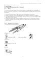
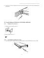
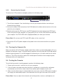
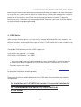
1
Dual Rail Modular KVM Console
with 15 / 17 / 19”LCD Panel
English
User Manual
For Installation into a 19” rack it is essential to precisely
follow the installation procedure as described in section
3.1.
Install the Console into a Cabinet
of this manual.
Tested to comply with FCC Standards
For Commercial Use Only!
© LINDY ELECTRONICS LIMITED & LINDY-ELEKTRONIK GMBH
SECOND EDITION (JULY 2008)
Dual Rail Console For Modular KVM Switch User Guide
Packing List
The complete 15 / 17 / 19” dual rail console for modular KVM switch package consists of:
•
•
•
•
•
•
•
•
•
•
1U 19” rack mount console
Rail with front and rear bracket x 2
Blockers x 2
1.8 m KVM cable. (HDDB-15 / VGA + PS/2 x 2)
AC to DC power adapter
User Guide CD
Quick installation guide
Key x 2
Flat screws (length 6mm) x 6
Screws (to combine blockers and console) x 2
Please read this manual thoroughly, and follow the installation and operation procedures carefully
to prevent any damage to the product, and / or any of the devices that connect to it.
1
Dual Rail Console For Modular KVM Switch User Guide
Safety Instructions
Please read these safety instructions carefully.
Please keep this User’s Manual for later reference.
Please disconnect this equipment from the AC outlet before cleaning. Do not use liquid or
sprayed detergent for cleaning. Use a moist sheet or cloth for cleaning.
It is recommended that for your convenience the equipment is installed near an easily
accessible power socket.
Please keep this equipment in a non-humid environment.
Before starting the installation ensure that your equipment is situated on a stable, level
surface. A drop or fall could cause injury.
Do not leave this equipment in an unconditioned environment, storage temperatures above
60 0C or humidity may damage to the equipment.
The opening on the enclosure is for air convection, to prevent the equipment from
overheating. DO NOT COVER THE OPENING.
Ensure that the voltage of the power source you are connecting to the equipment matches
the supported input voltage.
Please keep the power cord in such a way that people can not step or trip on it. Do not place
anything over power cord. The power cord must be correctly rated for the voltage and current
marked on the product’s electrical ratings label. The voltage and current rating of the cord
should be greater than the voltage and the current rating marked on the product.
All cautions and warning on the equipment MUST be noted.
If the equipment is not in use for a long period, disconnect the equipment from the mains to
avoid being damaged by transient over-voltage.
Never pour any liquid into the ventilation openings; this could cause a fire or an electrical
shock.
Never open the equipment. For safety, ONLY qualified service personnel should open the
equipment.
If one of the following situations arises, get the equipment checked by service personnel.
• The power cord or plug is damaged.
• The equipment has been exposed to moisture.
• The equipment has not worked well or you can not get it to work according to this
User Manual.
• The equipment has been dropped or damaged.
•
If the equipment shows obvious signs or breakage.
2
Dual Rail Console For Modular KVM Switch User Guide
Index of Contents
Packing List ............................................................................................................... 1
Safety Instructions ..................................................................................................... 2
Index of Contents ...................................................................................................... 3
1. General Information.............................................................................................. 4
1.1 Features ....................................................................................................... 4
1.2 Benefits ........................................................................................................ 4
1.3 Product Specification ................................................................................... 5
1.3.1 15" Dual Rail Console with Modular KVM Switch Specification .........5
1.4.2 17" Dual Rail Console with Modular KVM Switch Specification .........6
1.4.3 19" Dual Rail Console with Modular KVM Switch Specification .........7
2. Panel Controls & OSD Function........................................................................... 8
2.1 Auto Tune..................................................................................................... 8
2.2 Input Source................................................................................................. 8
2.3 Brightness .................................................................................................... 9
2.4 Contrast........................................................................................................ 9
2.5 Colour........................................................................................................... 9
2.6 Position ...................................................................................................... 10
2.7 Language ................................................................................................... 10
2.8 Reset to Factory Settings........................................................................... 10
2.9 Power Indicator .......................................................................................... 10
3. Installation .......................................................................................................... 11
3.1 Install Console into Cabinet ....................................................................... 11
3.1.1 Notes...................................................................................... ………11
3.1.2 Hardware Kits Contents....................................................................11
3.1.3 Installing the Console .....................................................................112
3.2 Install Modular KVM Switch ....................................................................... 13
3.2.1 Hardware Kits Contents....................................................................13
3.2.2 Install Modular KVM Switch Step......................................................13
3.3 Installing the Video Card and Video Driver ................................................ 15
3.3.1 Configuring the Display Settings.....................................................15
3.3.2 Connecting the Console..................................................................16
3.4 Turning the Console On ........................................................................... 16
3.5 Testing the Console ................................................................................. 16
4. KVM Switch ........................................................................................................ 17
3
Dual Rail Console For Modular KVM Switch User Guide
1. General Information
The LINDY Dual Rail consoles offer an industrial level input solution to optimize your space
utilization by controlling your systems in just 1U. With the unique modular design, you can
easily integrate with more than 17 models of KVM switch, with different functions, and
expand up to 8 levels of KVM switch.
1.1. Features
•
Patented Dual Rail design for independent Panel and Keyboard drawer
•
Hidden handle for keyboard drawer
15, 17 & 19” LCD panel options
Support Sun native resolutions (17” & 19”)
Support 17 keyboard languages
•
•
•
•
•
•
Bright Active TFT display
OSD function for LCD display and KVM switch
Durable keyboard ( touchpad, cherry keyboard or optical trackball)
•
Panel protected by tempered glass
Integration with more than 17 models of KVM switch
DC power, DVI, USB, Touch panel (optional)
•
Sun keys (optional)
•
•
1.2. Benefits
Patented Dual Rail design:
The user can leave the LCD flip over, push back the keyboard drawer, and close the
cabinet door.
Hidden handle:
After pushing the keyboard drawer back, the handle of the keyboard drawer can also be
hidden and offer a flat surface for the cabinet.
Patented extension bracket:
With the patented extension bracket, the console body can extend 13cm. Even if there is
a large server handle or patch panel above the console it will still provide over 90
degrees of viewing angle.
Modular KVM switches:
You can use the console as a single port console, however due to it’s modular design is
is very easy to add 8 / 16 or even 32 port KVM consoles, with little time or effort.
4
Dual Rail Console For Modular KVM Switch User Guide
1.3. Product Specification
1.3.1.
15" Dual Rail Console with Modular KVM Switch Specification
Model name
Number of ports
Dimension
Package Dimension
Net Weight
Gross Weight
Display Size
Panel Type
Resolution Capabilities
Pixel Pitch
Viewing Angle (CR>10)
Contrast Ratio
Brightness
Back Light
Supported Colors
Response Time
15” dual rail console with modular KVM switch
1
459.6 x 448.3 x 44 mm / 18.1 x 17.6 x 1.7 inches
606 x 551.5 x 230 mm / 23.9 x 21.7 x 9.0 inches
12 Kg / 26.5 lbs
19.5 Kg / 43.0 lbs
15 inches
Active Matrix TFT LCD
Maximum Resolution up to 1024 x 768 (XGA)
Supports 0.297 mm x 0.297 mm
Right-Left view 130°(Typ): Up-Down View 100°(Typ)
400:1
White 250 cd/m2
Dual Lamps for Back Light
16.7M Colors (8-bit with FRC)
Rising Time 5 ms, Decay Time 11 ms
Operating System
Dos, Windows (3.1, 9x, 2000, NT4, ME, XP, 2003 Server) Linux, Novell
3.12-6, HP UX, SUN
Multi Platform
System Cables
Keyboard Mouse
Sync
Power Source
Power Consumption
Support PS/2 and USB
VGA + PS/2 x 2 or VGA + USB x 1 cable
106 key PS/2 keyboard with touch pad
45 ~ 80 KHz
100 ~ 240 VAC input
16W, 10.41W for Panel
Temperature
Operate 0 ~ 50°C / 32 ~ 122°F
Storage -20 ~ 60°C / -4 ~ 140°F
Humidity
Chassis Construction
Keyboard Language
Certification
10% ~ 90% RH
Heavy duty steel materials
USA, UK, German, French, Spanish, Italian, Portuguese, Dutch, Swiss,
Belgium, Swedish, Norwegian, Danish, Japan, Taiwan, Russian,
Hebrew
CE / FCC, UL / CUL / C-Tick, GOST
15" Dual Rail Console with Modular KVM Switch Dimensions
5
Dual Rail Console For Modular KVM Switch User Guide
1.3.2. 17" Dual Rail Console with Modular KVM Switch Specification
Model name
Number of ports
Dimension
Package Dimension
Net Weight
Gross Weight
Display Size
Panel Type
Resolution Capabilities
Pixel Pitch
Viewing Angle (CR>10)
Contrast Ratio
Brightness
Back Light
Supported Colors
Response Time
17” dual rail console with modular KVM switch
1
459.6 x 448.3 x 44 mm / 18.1 x 17.6 x 1.7 inches
606 x 551.5 x 230 mm / 23.9 x 21.7 x 9.0 inches
13 Kg / 28.7 lbs
20.5 Kg / 45.2 lbs
17 inches
Active Matrix TFT LCD
Maximum Resolution up to 1280 x 1024 (SXGA)
Supports 0.264 mm x 0.264 mm
Right-Left view 60° ~ 70°(Typ): Up-Down View 45° ~ 60°(Typ)
450:1
White 250 cd/m2
Quad Lamps for Back Light
16.7M Colors (8-bit with FRC)
Rising Time 2 ms, Decay Time 14 ms
Operating System
Dos, Windows (3.1, 9x, 2000, NT4, ME, XP, 2003 Server) Linux, Novell
3.12-6, HP UX, SUN
Multi Platform
System Cables
Keyboard Mouse
Sync
Power Source
Power Consumption
Support PS/2 and USB
VGA + PS/2 x 2 or VGA + USB x 1 cable
106 key PS/2 keyboard with touch pad
45 ~ 80 KHz
100 ~ 240 VAC input
25W, 19.05W for Panel
Temperature
Operate 0 ~ 50°C / 32 ~ 122°F
Storage -20 ~ 60°C / -4 ~ 140°F
Humidity
Chassis Construction
Keyboard Language
Certification
10% ~ 90% RH
Heavy duty steel materials
USA, UK, German, French, Spanish, Italian, Portuguese, Dutch, Swiss,
Belgium, Swedish, Norwegian, Danish, Japan, Taiwan, Russian,
Hebrew
CE / FCC, UL / CUL / C-Tick, GOST
17" Dual Rail Console with Modular KVM Switch Dimensions
6
Dual Rail Console For Modular KVM Switch User Guide
1.3.3. 19" Dual Rail Console with Modular KVM Switch Specification
Model name
Number of ports
Dimension
Package Dimension
Net Weight
Gross Weight
Display Size
Panel Type
Resolution Capabilities
Pixel Pitch
Viewing Angle (CR>10)
Contrast Ratio
Brightness
Back Light
Supported Colors
Response Time
19” dual rail console with modular KVM switch
1
539.6 x 448.3 x 44 mm / 21.2 x 17.6 x 1.7 inches
606 x 551.5 x 230 mm / 23.9 x 21.7 x 9.0 inches
13 Kg / 28.7 lbs
21.5 Kg / 47.4 lbs
19 inches
Active Matrix TFT LCD
Maximum Resolution up to 1280 x 1024 (SXGA)
Supports 0.098 mm x 0.294 mm
Right-Left view 140°(Typ): Up-Down View 140°(Typ)
500:1
White 250 cd/m2
Quad Lamps for Back Light
16.7M Colors (8-bit with FRC)
Rising Time 2 ms, Decay Time 10 ms
Operating System
Dos, Windows (3.1, 9x, 2000, NT4, ME, XP, 2003 Server) Linux, Novell
3.12-6, HP UX, SUN
Multi Platform
System Cables
Keyboard Mouse
Sync
Power Source
Power Consumption
Support PS/2 and USB
VGA + PS/2 x 2 or VGA + USB x 1 cable
106 key PS/2 keyboard with touch pad
45 ~ 80 KHz
100 ~ 240 VAC input
25W, 21.05W for Panel
Temperature
Operate 0 ~ 50°C / 32 ~ 122°F
Storage -20 ~ 60°C / -4 ~ 140°F
Humidity
Chassis Construction
Keyboard Language
Certification
10% ~ 90% RH
Heavy duty steel materials
USA, UK, German, French, Spanish, Italian, Portuguese, Dutch, Swiss,
Belgium, Swedish, Norwegian, Danish, Japan, Taiwan, Russian,
Hebrew
CE / FCC, UL / CUL / C-Tick, GOST
19" Dual Rail Console with Modular KVM Switch Dimensions
7
Dual Rail Console For Modular KVM Switch User Guide
2. Panel Controls & OSD Function
Panel Controls
Description
Soft power on/off button. Adjacent LED is lit when on
Auto
Auto-synchronize and scale down display to any valid factory preset timings
Up
Press to scroll the function you want to adjust
Down
Press to scroll the function you want to adjust
Menu
To access the main menu. This button also acts as the “Enter” button
2.1. Auto Tune
1. Press Menu
2. Use the Up and Down buttons to scroll to Auto Tune
Auto tune
Input Source
Brightness
Contrast
Color
Position
Language
Recall
Exit
3. Press Menu to select Auto Tune
4. The panel will adjust the display size automatically and also tune the panel to its
best condition
2.2. Input Source
1. Press Menu
2. Use the Up and Down buttons to scroll to Input Source
Auto tune
Input Source
Brightness
Contrast
Color
Position
Language
Recall
Exit
3. Press Menu to enter
4. Use the Up and Down buttons to scroll to the signal input source.
5. Press Menu to enter
8
Dual Rail Console For Modular KVM Switch User Guide
2.3. Brightness
1. Press Menu
2.
3.
4.
5.
Use the Up and Down buttons to scroll to Brightness
Press Menu to enter
Use the Up and Down buttons to adjust the Brightness of the display
Press Menu to enter
2.4. Contrast
1. Press Menu
2. Use the Up and Down buttons to scroll to Contrast
3. Press Menu to enter
4. Use the Up and Down buttons to adjust the Contrast of the display
5. Press Menu to enter
2.5. Colour
1. Press Menu
2. Use the Up and Down buttons to scroll to Color
3. Press Menu to enter. You will see:
Icon
Description
9300°K
To set CIE coordinates at 9300°K color
7500°K
To set CIE coordinates at 7500°K color
6500°K
To set CIE coordinates at 6500°K color
User
To set user defined CIE
Auto
color
To auto adjust color
Return
To exit and return to the previous page
4. Use the Up and Down buttons to adjust the Colour of the display
5. Press Menu to enter
9
Dual Rail Console For Modular KVM Switch User Guide
2.6. Position
1. Press Menu
2. Use the Up and Down buttons to scroll to Positioning
3. Press Menu to enter. You will see:
Icon
Description
Image Pos
To adjust the position of the
image.
OSD Pos
To adjust the position of the OSD.
Return
To exit and return to the previous
page
4. Use the Up and Down buttons to choose which Position you want to change
5. Press Menu to enter
2.7. Language
1. Press Menu
2. Use the Up and Down buttons to scroll to Language
3. Press Menu to enter. You will see:
English
German
French
Italian
Spanish
4. Use the Up and Down buttons to scroll to highlight your preferred language
5. Press Menu to enter
2.8. Reset to Factory Settings
1. Press Menu
2. Use the Up and Down buttons to scroll to Recall
3. Press Menu to enter. You will see:
Yes/ No
4. Use the Up and Down buttons to scroll, select Yes then press Menu to reset to
factory settings. Select No to return to the previous page.
2.9. Power Indicator
GREEN
RED
RED
RED
ON
STANDBY
SUSPEND
OFF
10
Dual Rail Console For Modular KVM Switch User Guide
3. Installation
3.1. Install the Console into a Cabinet
3.1.1.
Notes
It is essential that each step of this installation guide is completed in the stated order to
ensure a successful installation. It is highly recommended that two persons carry out the
installation.
1. Please the contents of this box against the list below, before installation.
2. Before installation, make sure all peripherals and computer have been turned off.
3. The cabinet depth range must be in 570 ~ 870 mm for the 15” and 17” console or 650 ~
950 mm for the 19” console.
4. Reliable earthing of rack-mounted equipment must always be maintained. Particular
attention should be given to supply connections other than direct connections to the
branch circuit.
3.1.2. Hardware Kits Contents
1. Rail with front and rear bracket x 2
2. Blocker x 2
Old version (2007)
New version (2008)
3. Screw x 2
4. Screw (length = 6 mm) x 6
5. Key x 2
11
Dual Rail Console For Modular KVM Switch User Guide
3.1.3.
Installing the Console
1. Adjust the rail with the rear bracket to fit your cabinet
2. Attach the front and rear brackets to your cabinet
3. Repeat steps 1 and 2 for the other side of your cabinet
4. Slide the console along the rails until you reach the end
5. Use a screw to connect the blocker to the rear of the console at each side
Old version (2007)
New version
2008
12
Dual Rail Console For Modular KVM Switch User Guide
6. Install three screws (length 6mm) to the rear of the console at each side to complete the
installation
3.2. Install Modular KVM Switch (OPTIONAL MODULE)
3.2.1.
Hardware Kits Contents
1. Bracket A with thumb screw x 2
2. Screw (length 6 mm) x 4
3.2.2. Install Modular KVM Switch Step
1. Install two screws (length 6mm) to attach Bracket A to the KVM Switch at each side
13
Dual Rail Console For Modular KVM Switch User Guide
2. From the rear of the cabinet slide the KVM Switch along the rails, until it reaches the
console and the thumb screws are aligned to the rear of the cabinet
Plastic Rail on KVM Switch
Rear View of Rail
3. Tighten the Thumb Screws of Bracket A, at each side, to fix the position of the KVM
Switch and complete the installation
14
Dual Rail Console For Modular KVM Switch User Guide
3.3. Installing the Video Card and Video Driver
Before connecting the LCD console, make sure your computer has a video card already installed for
the monitor. After you connect the console, install the video driver. The video driver is supplied by
the video card manufacturer and may be found on the CD-ROM that came with your computer. If
you need information on installing a video card or video driver, refer to the manual that came with
your video card.
3.3.1.
Configuring the Display Settings
After connecting the console and turning on your computer, you may need to configure one or
more of the following display settings:
•
Display mode (also called desktop area or video resolution)
•
Refresh rate (also called vertical scan rate or vertical sync)
Color depth (also called color palette or number of colors)
•
Each video card has several controls that let you adjust the display settings. However, the
software and driver for each video card is unique. In most cases, you adjust these settings by
using a program or utility provided by the manufacturer of the video card. Most video cards use the
Windows Display Properties control panel to configure the display. To open the Windows Display
Properties, click the right mouse button in a blank area of the Windows desktop and then select
Properties. The Settings tab lets you change the Color Palette and the Desktop Area (x by y
pixel resolution).
Some video cards integrate additional features into the Windows Display Properties control panel
to give you an exceptional setup that is flexible and easy to use. For example, the control panel
may include an Advanced Properties button, an Adjustment tab, or a Refresh tab for changing
other settings. Other video cards have a separate utility for setting display properties.
Whenever you change the resolution, color, or refresh rate, the image size, position, or shape
may change. This behavior is normal. You can readjust the image using the monitor on-screen
controls. For more information on the monitor on-screen controls, refer to Chapter 2. For more
information on configuring the display settings, refer to the manual that came with your video
card.
15
Dual Rail Console with Modular KVM Switch User’s Manual
3.3.2.
Connecting the Console
To connect an LCD console to a computer, perform the following steps
PS/2-USB switch
1. Turn off your computer. You should always turn off your computer before connecting or
disconnecting a device.
2. Connect the video (VGA) connector of the KVM cable to the video card connector on the rear
panel of your computer.
3. Identify and connect the PS/2 mouse and PS/2 keyboard connector to the correct PS/2 ports
on the rear panel of your computer, or if you prefer you can use the USB interface to connect
your computer. Use PS/2-USB switch (highlighted above) to select your interface.
Please Note: Do not connect PS/2 and USB cables at the same time!
4. Connect the AC to DC power adapter to the power inlet on the console and then to a power
outlet.
3.4. Turning the Console On
Make sure that the AC to DC power adapter and all other cables are connected properly. Be sure
to tighten all connector screws. Using two hands, grasp the rear of the console, lift the tab and pull
the panel up and forward. This will disengage the momentary on / off switch and the unit should
power on. The LED on the left or under of the monitor panel should turn from orange to green,
verifying that the unit is operational.
3.5. Testing the Console
To test that the console is working properly, perform the following steps:
1. Power up the console, and then turn on your computer
2. If the unit does not power up when the panel is pulled up, try pushing the soft power
on/off button on the left or under side of the monitor panel to power up the unit.
3. Make sure the video image is centered within the screen area. Use the OSD controls to adjust
the image (see note below) or press the Auto button on the right hand side of the monitor.
Please Note: You can adjust the horizontal and vertical position, contrast, and brightness to
16
Dual Rail Console with Modular KVM Switch User’s Manual
better suit your video card and your personal preference. Refer to Chapter 2 for more information
on using the on-screen menu to adjust the video display. Before you begin, make sure that
powers to all the devices you will be connecting up have been turned off. To prevent
damage to your installation due to ground potential difference, make sure that all the devices
on the installation are properly grounded.
4. KVM Switch
With a unique modular design, you can easily integrate different KVM switch models, with
different functions, and expand them up to 8 levels of KVM switch with a total number of up
to 128 servers to manage.
Compatible KVM Switches from the LINDY range are:
KVM Switch U8C Modular – No. 39530 *
KVM Switch U16C Modular – No. 39531 *
* These two models can easily be expanded by using a simple slide-in-module to provide
a remote access dual user option for a) KVM over IP access module or b) Cat.5 KVM
Extender remote user station
Further models are under development – Please check the LINDY website www.lindy.com
for up to date information and new products.
Please refer to the user guide supplied with your KVM switch for information on installation
and operation.
For Installation of the KVM Switch module it is essential to follow the
installation procedure as described in section
3.2. Install Modular KVM Switch (OPTIONAL MODULE)
of this manual.
17
WEEE, Recycling of Electronic Products (Europe)
WEEE (Waste of Electrical and Electronic Equipment),
Recycling of Electronic Products
In 2006 the European Union introduced regulations (WEEE) for the collection and recycling
of all waste electrical and electronic equipment. It is no longer allowable to simply throw
away electrical and electronic equipment. Instead, these products must enter the recycling
process.
Each individual EU member state has implemented the WEEE regulations into national law
in slightly different ways. Please follow your national law when you want to dispose of any
electrical or electronic products.
More details can be obtained from your national WEEE recycling agency.
Germany / Deutschland
Die Europäische Union hat mit der WEEE Direktive umfassende Regelungen für die
Verschrottung und das Recycling von Elektro- und Elektronikprodukten geschaffen. Diese
wurden von der Bundesregierung im Elektro- und Elektronikgerätegesetz – ElektroG in
deutsches Recht umgesetzt. Dieses Gesetz verbietet vom 24.März 2006 an das Entsorgen
von Elektro- und Elektronikgeräten über die Hausmülltonne!
B2B Geräte wie dies LINDY LCD Terminal und LINDY 19“ KVM Switches nimmt LINDY
kostenlos zurück und führt sie einem geordneten Recycling entsprechend den gesetzlichen
Vorgaben zu. Bitte nehmen Sie hierzu Kontakt mit LINDY auf, die Kontaktadressen finden
Sie stets auf der LINDY Website www.lindy.com
B2C-Geräte müssen den lokalen Sammelsystemen bzw. örtlichen Sammelstellen
zugeführt werden! Dort werden sie kostenlos entgegen genommen. Die Kosten für den
weiteren Recyclingprozess übernimmt die Gesamtheit der Gerätehersteller.
Radio Frequency Energy, Certifications
Shielded cables must be used with this equipment to maintain compliance with radio
frequency energy emission regulations and ensure a suitably high level of immunity to
electromagnetic disturbances.
FCC Warning
This equipment has been tested and found to comply with the limits for a Class B digital
device, pursuant to part 15 of the FCC Rules. These limits are designed to provide
reasonable protection against harmful interference in a residential installation.
This equipment generates, uses, and can radiate radio frequency energy and, if not installed
and used in accordance with the instructions, may cause harmful interference to radio
communications. However, there is no guarantee that interference will not occur in a
particular installation. If this equipment does cause harmful interference to radio or television
reception, which can be determined by turning the equipment off and on, the user is
encouraged to try to correct the interference by one or more of the following measures:
Reorient or relocate the receiving antenna
Increase the separation between the equipment and receiver
Connect the equipment into an outlet on a circuit different from that to which the receiver
is connected
Consult the dealer or an experienced technician for help
You are cautioned that changes or modification not expressly approved by the party
responsible for compliance could void your authority to operate the equipment.
This device complies with part 15 of the FCC Rules.
Operation is subject to the following two conditions:
1. This device may not cause harmful interference, and
2. This device must accept any interference received, including interference that may
cause undesired operation.
2nd Edition, July 2008
Tested to comply with FCC Standards
For Commercial Use Only!
www.lindy.com