1
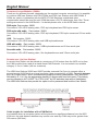
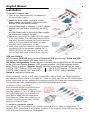
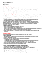
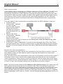
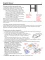
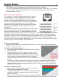
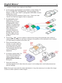
KVM Extender User Station & Cat.5 KVM Extender User Manual English LINDY No. 32357, 32358, 32359 LINDY No. 39356, 39357 Tested to Comply with FCC Standards For Commercial Use Only! www.LINDY.com © LINDY ELECTRONICS LIMITED & LINDY-ELEKTRONIK GMBH - SECOND EDITION (FEB 2008) English Manual 2 Introduction Thank you for choosing the KVM Extender User Station Product series from LINDY. Each of the models have been designed to take full advantage of CAT.x structured cabling (where x means category 5, 5e or 6) to provide high quality linking plus ultimate flexibility for installers and operators alike. The User Stations can be either used in conjunction with LINDY MC5 KVM Switches or also as a CAT.5 Extender Product in combination with the Computer Access Modules (CAM). In the latter case a USB User Station can be used with a PS/2 CAM and vice versa. User Stations and Cams are available with and without Audio. User Stations are also available in a long distance VGA version with integrated Skew compensation allowing VGA resolutions of up to 1600x1200 even at distances of 300m. Standard versions of the User Station support VGA resolutions up to 75m@1600x1200 or 200m@1280x1024. However, this distance reduces depending on the video resolution used. Remote User Stations Currently 5 different versions of the User Station are available. Each User Station module is supplied with its own power adapter and country-specific power lead. KVM Extender User Station C5 Junior, Part number: 32357 For PS/2 keyboard & mouse and VGA up to 200m distance. Connectors: VGA HD15 analog video, PS/2-style keyboard and PS/2-style mouse. KVM Extender User Station C5 Audio, Part number: 32359 For PS/2 keyboard & mouse, Audio stereo speakers and VGA up to 200m distance. Connectors: VGA HD15 analog video, PS/2-style keyboard and PS/2-style mouse and 3.5mm audio jack. KVM Extender User Station C5 Pro 300m, Part number: 32358 For PS/2 keyboard & mouse, Audio stereo speakers and VGA up to 300m distance. Includes additional skew compensation features. Connectors: VGA HD15 analog video, PS/2-style keyboard and PS/2-style mouse and 3.5mm audio jack. KVM Extender User Station USB, Part number: 39357 For USB keyboard & mouse and VGA up to 200m distance. Includes KVM Switch with two Cat.x outputs, either local & remote or 2x remote. Connectors: VGA HD15 analog video, USB keyboard and USB mouse. KVM Extender User Station USB 300m, Part number: 39356 For USB keyboard & mouse, Audio stereo speakers and VGA up to 300m distance. Includes additional skew compensation function. Includes KVM Switch with two Cat.x outputs, either local & remote or 2x remote. Connectors: VGA HD15 analog video, USB keyboard and USB mouse and 3.5mm audio jack. English Manual 3 Computer Access Modules (CAMs) There are five different formats, depending on the required computer connections. It is possible to combine USB user Stations with PS/2 CAMs and PS/2 User Stations with USB CAMs. If CAMs are used in combination with the MC5/-IP KVM Switches a dedicated video compensation should be used for each CAM that uses a CAT.5 cable longer than 10m. These settings are stored in the KVM Switch – for details please refer to the KVM Switch manual. PS/2-style, Part number: 39351 Connectors: VGA HD15 analog video, PS/2-style keyboard and PS/2-style mouse. PS/2-style with audio, Part number: 39353 Connectors: VGA HD15 analog video, PS/2-style keyboard, PS/2-style mouse and 3.5mm audio jack. USB, Part number: 39352 Connectors: VGA HD15 analog video and USB keyboard/mouse. USB with audio, Part number: 39354 Connectors: VGA HD15 analog video, USB keyboard/mouse and 3.5mm audio jack. Sun with audio, Part number: 39355 Connectors: VGA HD15 analog video, Sun keyboard/mouse and 3.5mm audio jack. Remote user (via User Station) A remote User Station can be placed at a maximum of 300 metres from the MC5 unit or from the CAM module when used as a stand alone KVM Extender. It is connected via a suitable category 5, 5e or 6 cable (with no crossover). The USB User Stations 39356 and 39357 provide a second Cat.5 port to connect either a second remote KVM Switch or a local computer (also connected by a CAM). To switch between the Cat.5 output ports 1 and 2 simultaneously press the hotkey combination CTRL and SHIFT followed by 0, 1 or 2 for the appropriate channel (0 disconnects from both ports). This hotkey can be changed to ALT & SHIFT or CTRL & ALT by DIP switches (see section Installation). The USB User Stations also provide the option to set a password and lock the User Station. Cable lengths for installation with a KVM Switch In situations where a computer system will be placed at a significant distance from the MC5 KVM unit, the total distance between any remote user and any CAM may not be greater than 300 metres (980 feet). English Manual 4 Installation To connect a remote user 1 Place a User Station extender unit adjacent to the remote user location. 2 Attach the video monitor, keyboard, mouse, power adapter (and speaker) connectors to the sockets of the User Station module. 3 Lay a suitable length of category 5, 5e or 6 cabling between the User Station module and the MC5 unit or CAM. Please refer to the section Cable lengths for remote user locations opposite. 4 Attach the connector of the cable run to the socket of the User Station. The USB User Stations 39356 and 39357 provide a second Cat.5 port to connect either a second remote KVM Switch or a local computer (also connected by a CAM). 5 At the other end of the cable run, attach the cable connector to one of the sockets labelled CAT.x USER PORTS on the rear panel of the MC5 unit or to a CAM when used as stand alone extender. USB User Stations LED indicators: RED LED: power present; Green port LED: port selected; Yellow port LED: flashing: active data transfer / ON when linked to a CAM. DIP Switch Configurations: Certain aspects of operation can be affected by the DIP switches on the USB User Stations. Switch 1: OFF: Normal operation / ON: Flash Upgrade (switch before Power is applied). Switches 2 and 3 determine which two keyboard keys are used: 2 ON & 3 OFF Hotkeys = CTRL and ALT 2 OFF & 3 OFF Hotkeys = CTRL and SHIFT 2 OFF & 3 ON Hotkeys = ALT and SHIFT 2 ON & 3 ON Hotkeys disabled Switch 4: reserved for future use. Where necessary, use the in-built video compensation feature of the User Station module to eliminate any effects caused by the cable run. However, when used with the MC5 KVM Switch series, ensure that the links between the computers and the MC5 have been compensated first. See remote user video compensation in the KVM Switch manual for details. Computer system (via CAM) Each computer system is connected via a Computer Access Module (CAM) and standard category 5, 5e or 6 cabling, either to a KVM Switch MC5 unit or directly to a User Station when used as stand alone KVM Extender. CAMs are available to suit different computer system types and their particular connector styles. To connect a computer system Connect the CAM connectors to the computer keyboard, mouse, video and audio ports. To establish PS/2 connections, in most cases, a reboot of the computer is required, whereas USB, VGA and Audio connections are hot pluggable. English Manual 5 Operation Selecting and using computers To select a system using the keyboard: Use the hotkey to switch between the two computer systems. In each case, you need to simultaneously press the currently configured hotkeys (by default, CTRL and SHIFT) together with the number of the required system 1 or 2. To disconnect from both systems press the hotkeys followed by 0. Locking and unlocking the system In situations where the computer systems (and their local CAMs) can be locked away, the USB User Station offers a security system to deter unauthorised use. Once a password has been set, a simple key sequence allows each system to be quickly and securely detached from the common peripherals. Only the correct password will reconnect the modules. To lock the system 1. First set a password. For further details, please refer to the Password setting section. 2. Simultaneously press the currently configured hotkeys followed by L. The screen will go blank and the three keyboard indicators will begin alternately flashing between the ‘Num Lock’ and ‘Scroll Lock’, and ‘Caps Lock’. This sequence indicates that a password is required. Additionally neither of the green indicators adjacent to the RJ45 connectors on the User Station will be lit. To unlock the system 1. Enter the correct password and press RETURN. Note 1: Passwords are NOT case sensitive. Note 2: If an invalid password has been entered and the keyboard indicators are not flashing as described above, press RETURN to clear the incorrect attempt. 2. If the correct password is entered, the screen will be restored and normal operation can continue. Password setting Password protection allows you restrict access to the USB User Station. To set a password 1. Simultaneously, press the hotkeys followed by RETURN to enter configuration mode. 2. Press P followed by RETURN. 3. Now enter your new password, within the following constraints: • Passwords are NOT case sensitive, • Passwords may be any length from one character to a maximum of forty characters, • The following keys may NOT be used: CTRL, ALT, SHIFT or RETURN. 4. When you have entered the password, press RETURN to signal its completion. 5. Press RETURN once more to exit configuration mode. To clear a password (and restore factory default settings) 1. Connect the User Station to a computer by one USB port only. 2. While power is applied, set the units upgrade switch SW1 to its ON position. 3. Remove power from the unit and then re-apply power. 4. Set the computer serial settings to the following: 19200, n, 8, 1 5. Using a terminal program, send “CLEAR<cr>” - in upper or lower case from the keyboard. The User Station should respond with “OK”. 6. The password is now clear and all factory default settings restored. English Manual 6 Video compensation A User Station may be connected to a CAM by a maximum of 300m (980 feet). The MC5 units allow computer systems to be placed up to 50m (160 feet) away and remote users to be extended by a maximum of 300m (980 feet) including the largest distance between any CAM and the MC5. Such long cable lengths can affect video signals, especially when higher screen resolutions are used. In order to eliminate any video signal degradation, all MC5 units and accompanying User Station modules provide effective software-based video compensation features. Two main types of video compensation are provided within the MC5 installation, these are: Computer video compensation - operates on video signals between each computer system and the MC5 unit. See the manual of the KVM Switch MC5 for details! Remote user video compensation - operates on video signals between each remote user(s) and the MC5 unit or between a User Station and a CAM. See Remote user video compensation for details. A third type of video compensation is provided by the advanced video 300m User Station extender modules only. This type of compensation is called Skew adjustment and combats the effect of uneven twisted pairs within link cables. See Remote user skew adjustment for details. Remote user video compensation Video compensation for each remote user is provided by the User Station modules. Using the User Station controls you can adjust the picture sharpness and brightness to improve the remote picture quality. Note: Accurate remote user compensation relies upon visual feedback from the screen image. It is therefore vital to ensure that the video images being transmitted are as ‘true’ as possible. Video compensation is best carried out when viewing high contrast images with vertical edges, such as black lines on a white background. When doing so, if you notice that the screen image is ‘fuzzy’ or ‘dark’ then the image controls may not be able to solve this condition. Note: If the high contrast images exhibit shadows with separate colours, then there may be a skew problem introduced by the Cat.5 connection cable. Due to the different length of the twisted pairs in any Cat.5 cable different propagation delays for the Red, Green and Blue video colour signals are introduced which requires a different image adjustment (provided only by advanced video 300m User Station C5 Pro and USB 300m modules) or the uses of a separate Skew Compensator (LINDY part no. 39389) - see the Remote user skew adjustment section for details. English Manual 7 To display a suitable high contrast image The best way to clearly view the effect of sharpness and brightness adjustments is to display a high contrast image, with vertical edges, on the screen. • Open a word processor, type the capital letter ‘H’, or ‘M’ and increase the point size to 72 or higher. For best results, the background should be white and the character should be black. • A BLACK shadow on the right of the character indicates UNDER compensation. • A WHITE shadow on the right of the character indicates OVER compensation. Note: The Word processor method is accurate and quick. However, for the very finest video compensation, use the latest “skew” test pattern program which shows both the skew pattern and a section of mixed size Hs (black on white and white on black). If the image controls cannot provide a crisp image If, after adjusting the image controls, one or more screen images remain fuzzy or have coloured shadows you may need to use the Skew adjustment feature. Please see Remote user skew adjustment for details (User Station C5 Pro module only). To apply remote user video compensation 1. When used with a KVM Switch MC5 first ensure that the video image from the computer to the KVM Switch has been correctly compensated. 2. On the remote user keyboard (connected to a User Station extender), simultaneously, press the hotkeys (by default, <CTRL> and <SHIFT>) along with <RETURN> to enter configuration mode. The three keyboard indicators (‘Num Lock’, ‘Caps Lock’ and ‘Scroll Lock’) will now begin to flash in sequence. The speed of the sequence indicates the level of the sharpness adjustment currently applied: the slower the rate, the lower the level of sharpness being applied. 3. While viewing the displayed screen image, use the following keys to adjust the controls: Sharpness: To autoset sharpness: Press F and 2 and <RETURN> to make the module calculate and apply an automatic compensation level - you can use this as a starting point for your fine tuning. ↑ and ↓ for fine adjustment, <PAGE UP> and <PAGE DOWN> for coarse adjustment. There are 255 sharpness levels (one coarse step jumps 10 levels). Note: If the monitor goes blank and switches off (due to oversetting the sharpness adjustment) press the Home key to restore. 4. Brightness: ← and → for adjustment. There are 255 brightness levels. English Manual 8 5. When no shadows are visible and the displayed images have crisp edges, press <RETURN> to exit configuration mode and permanently save all settings. The new compensation settings will be stored, even when power is removed or if a complete reset is initiated. These settings should not require further changes unless the cabling arrangements are altered. Remote user skew adjustment The category 5, 5e and 6 cabling consists of four pairs of wires per cable. Three of these pairs are used to convey red, green and blue video signals to the remote video monitor. Due to the slight difference in twist rate between these three pairs, the red, green and blue video signals may not arrive at precisely the same time. This is visible as separate colour shadows on high contrast screen images and is particularly apparent when using higher screen resolutions. To alleviate this situation, the User Station C5 Pro and USB 300m modules provide internal skew adjustment that can help to rectify the situation. The skew adjustment works by delaying or advancing the timing of any of the red, green or blue colour signals so that they are all delivered to the monitor at precisely the same time. For best results, the “skew” program supplied on the disk is the most accurate way of setting skew as the red, green and blue lines are rendered exactly on the screen as single pixel wide lines. The skew.bmp test pattern can also be used but it is less accurate. Alternatively, you can create your own skew pattern using a standard image creation package, as detailed below. To use skew adjustment 1. Display a skew pattern on the appropriate computer. You can either use the supplied skew pattern or create your own: Using the supplied skew pattern a. Insert the supplied Installation CD-ROM into the CD player of the computer. b. Within Windows, use the My Computer option (usually available as a desktop icon or within the Start menu) to view the contents of the CD-ROM. Double-click the Skew entry to display the standard test pattern. If necessary, maximise the application window so that the image fills the screen. The screen will show a series of fine red, green and blue crosses which should all be in line, vertically and horizontally. Skew affects the horizontal placement of the colours and using this pattern it is much easier to discover which, if any, colours are being adversely affected by the cable link. Creating a skew test pattern a. Run any image creation/editing application, such as the Paint program supplied with Windows. b. Using the image application create three stacked horizontal rectangles (one red, one green and one blue) that fill the width of the screen. c. Draw a vertical black line down across the coloured bars and then repeat this vertical line at intervals along the width of the coloured bars. These lines English Manual 9 create breaks across the colours and give you more opportunities to view the horizontal position of each colour relative to the others. 2. On the remote user keyboard (connected to a User Station C5 Pro or C5 USB 300), simultaneously, press the hotkeys (by default, <CTRL> and <SHIFT>) along with <RETURN> to enter configuration mode. The three keyboard indicators (‘Num Lock’, ‘Caps Lock’ and ‘Scroll Lock’) will now begin to flash in sequence. 3. As appropriate, press either the R, G or B keyboard keys to select the appropriate colour channel. Corresponding keyboard indicators will flash rapidly to show which channel is currently selected for adjustment: Num Lock for Red, Caps Lock for Green and Scroll Lock for Blue. 4. Press the ← and → keys to retard or advance the timing of the selected colour channel respectively. On screen you will see a change in the position of the selected colour crosses (or colour bars) in relation to the other two. 5. When the selected colour crosses (or colour bars) are correctly positioned, press to exit that colour channel. The keyboard indicators will return to flashing in sequence. 6. If required, repeat steps 3 to 5 to select and adjust any colour channel until the vertical lines of the red, green and blue crosses are all aligned. 7. When all colours are correctly aligned on all video channels, press to exit configuration mode and permanently save all settings. Note: Once you have made the skew adjustments, it may be necessary to re-adjust the image controls to attain optimum screen images. Radio Frequency Energy, Certifications Shielded cables must be used with this equipment to maintain compliance with radio frequency energy emission regulations and ensure a suitably high level of immunity to electromagnetic disturbances. FCC Warning This equipment has been tested and found to comply with the limits for a Class B Digital device, pursuant to part 15 of the FCC Rules. These limits are designed to provide reasonable protection against harmful interference in a residential installation. This equipment generates, uses, and can radiate radio frequency energy and, if not installed and used in accordance with the instructions, may cause harmful interference to radio communications. However, there is no guarantee that interference will not occur in a particular installation. If this equipment does cause harmful interference to radio or television reception, which can be determined by turning the equipment off and on, the user is encouraged to try to correct the interference by one or more of the following measures: y Reorient or relocate the receiving antenna y Increase the separation between the equipment and receiver y Connect the equipment into an outlet on a circuit different from that to which the receiver is connected y Consult the dealer or an experienced technician for help You are cautioned that changes or modifications not expressly approved by the party responsible for compliance could void your authority to operate the equipment. CE Statement, EMC Compatibility This device complies with EN Standards EN55022 and EN55024 according to the relevant EC EMC Directive. It must be used with shielded cables only to maintain EMC compatibility. Dieses Produkt entspricht den einschlägigen EMV Richtlinien der EU und darf nur zusammen mit abgeschirmten Kabeln verwendet werden. LINDY Herstellergarantie LINDY gewährt für dieses Produkt über die gesetzliche Regelung hinaus eine zweijährige Herstellergarantie ab Kaufdatum. Die detaillierten Bedingungen dieser Garantie finden Sie auf der LINDY Website aufgelistet bei den AGBs. WEEE (Waste of Electrical and Electronic Equipment), Recycling of Electronic Products In 2006 the European Union introduced regulations (WEEE) for the collection and recycling of all waste electrical and electronic equipment. The wheelie bin symbol shown indicates that this product must not be disposed of with household waste. Instead the product must be recycled in a manner that is environmentally friendly. For more information on how to dispose of this product, please contact your local recycling centre or your household waste disposal service. Each individual EU member state has implemented the WEEE regulations into national law in slightly different ways. Please follow your national law when you want to dispose of any electrical or electronic products. Germany / Deutschland Die Europäische Union hat mit der WEEE Direktive umfassende Regelungen für die Verschrottung und das Recycling von Elektro- und Elektronikprodukten geschaffen. Diese wurden von der Bundesregierung im Elektround Elektronikgerätegesetz – ElektroG in deutsches Recht umgesetzt. Dieses Gesetz verbietet vom 24.März 2006 an das Entsorgen von Elektro- und Elektronikgeräten über die Hausmülltonne! Diese Geräte müssen den lokalen Sammelsystemen bzw. örtlichen Sammelstellen zugeführt werden! Dort werden sie kostenlos entgegen genommen. Die Kosten für den weiteren Recyclingprozess übernimmt die Gesamtheit der Gerätehersteller. B2B Geräte wie 19“ KVM Switches und ihr Zubehör nimmt der Hersteller LINDY kostenlos zurück und führt sie sodann auf LINDYs Kosten dem geregelten Recyclingprozess zu. Tested to Comply with FCC Standards For Commercial Use Only! © LINDY ELECTRONICS LIMITED & LINDY-ELEKTRONIK GMBH - SECOND EDITION (FEB 2008)