1
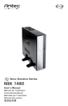
Atlas 550 Quiet Mini Server Case User’s Manual Manuel de l’utilisateur Anwenderhandbuch Manuale per l’operatore Manual del usuario পᡅ䂀ᯢ At Antec, we continually refine and improve our products to ensure the highest quality. It’s possible that your new case will differ slightly from the descriptions in this manual. This isn’t a problem; it’s simply an improvement. As of the date of publication, all features, descriptions, and illustrations in this manual are correct. Disclaimer This manual is intended only as a guide for Antec’s Computer Enclosures. For more comprehensive instructions on installing the motherboard and peripherals, please refer to the user’s manuals that come with those components. Atlas 550 User’s Manual Atlas 550 – Quiet Mini Server Case This case comes with a TruePower Trio™ 550 Watt power supply unit (PSU). It complies with the newest Intel® EPS12V specification. The PSU comes with a main power switch. Make sure you turn the switch to the ON (I) position before you boot up the computer for the first time. Normally, you won’t need to switch to the OFF (O) position, since the PSU includes a soft on/off feature. This lets you turn the computer on and off by using the soft switch on the computer case. If the computer crashes and you can’t shut it down using the soft switch, you can switch the main power to the OFF (O) position to shut the system down. Then turn the switch back to the ON (I) position and reboot. Antec TruePower Trio™ power supplies feature Power Factor Correction (PFC) circuitry in accordance with European standard regulation code EN61000-3-2. By altering the input current wave shape, PFC improves the power factor of the PSU. A better Power Factor increases energy efficiency, reduces heat, improves output voltage stability and prolongs the life of all equipment. The PSU’s high efficiency design and quiet fan deliver not only a cleaner but also a quieter operating environment. Although care has been taken to prevent sharp edges in your Antec case, we strongly recommend taking your time and the appropriate care when working with it. Hurried or careless motion and use of excessive force, particularly when you are working in areas you cannot see clearly, are but a few examples of activity that should be avoided. Please use reasonable precaution. Setting Up 1. 2. 3. 4. 5. Place the case upright on a flat, stable surface. Loosen the thumbscrews from the right side panel and remove it by swinging it out. Note: Do not use your fingernails to pry or lift the panels. Inside the case you should see the power supply, some wiring with marked connectors (USB, PWR etc.), the installed I/O panel, a power cord, a plastic bag containing more hardware (screws, brass standoffs, etc.), and six drive rails. There are three plastic tabs on the left side of the bezel that fasten it to the metal chassis. Release the tabs from the top down to release the bezel. Swing the bezel open to about 45º, gently lift it up and it will come off easily. Set the bezel aside in a safe place. 1 Installing the Motherboard This manual does not cover CPU, RAM, or expansion card installation. Please consult the motherboard manual for specific mounting instructions and troubleshooting. 1. 2. 3. 4. 5. 6. 7. Lay the case down with the open side facing up. The drive cages and power supply should be visible. Make sure you have the correct I/O panel for the motherboard. If the panel provided with the case isn’t suitable, please contact the motherboard manufacturer for the correct I/O panel. Line up the motherboard with the standoff holes, and remember which holes are lined up. Not all motherboards will match with all the provided holes; this is normal and won’t affect functionality. Remove the motherboard. Screw the brass standoffs into the threaded holes that line up with the motherboard. Note: Do not over-tighten the standoffs. Some standoffs may be pre-installed for your convenience. Place the motherboard on the brass standoffs. Screw in the motherboard to the standoffs with the provided Philips-head screws. The motherboard is now installed. Picture 1 Connecting the Power and LED 1. 2. 3. 4. 5. Picture 2 Connect the 24-pin Main Power Connector and the 4-pin +12V connector to your motherboard as needed. If your motherboard uses a 20-pin connecFor 20-pin For 24-pin tor, detach the 4-pin attachment on the 24-pin power motherboards motherboards connector. (see pictures 1 and 2). Connect the Reset switch (labeled RESET SW) to your motherboard at the RST connector. Connect the 4-pin molex connector from the front display to a 4-pin molex connector on the power supply. The Power Switch (labeled POWER SW) connector connects to the PWR connector on the motherboard. The Hard Drive LED (labeled H.D.D. LED) connector connects to the hard drive activity header. Power supply 3-PIN fan signal connector A three-pin signal connector with blue and black wires is available to connect the power supply to one of your motherboard’s fan connectors (Note: Some motherboards have a dedicated fan connector labeled PWR-FAN or PSU-FAN that is specifically for the power supply). This connector is for monitoring the power supply’s fan speed only. It is optional—the power supply and its fan will operate normally whether this cable is connected to your motherboard or not. The fan speed can be monitored through the BIOS or special monitoring software that came with your motherboard. To ensure proper monitoring of the power supply fan, please check your motherboard manual. Note: At low temperatures, the fan may run as slow as 750 RPM (±10%). At these speeds, some motherboards may not properly detect the fan speed and may generate false warnings of fan failure. 2 Connecting the USB Ports You will find a single 10-pin connector on a cable attached to the front USB ports. This is an Intel® standard connector that is keyed so that it can’t be accidentally reversed when connected to a proper Intel® standard motherboard header. Connect the 10-pin connector to the motherboard headers so that the blocked pin fits over the missing header pin. Note: Please check the motherboard manual for the USB header pin layout and make sure it matches the table below. If it does not match this Intel® standard, please visit Antec’s web store at http://www.antec.com/StoreFront.bok and search for part number 30095 to order a USB Internal Adapter Cable. This adapter will allow you to connect the front USB to your motherboard on a pin-by-pin basis. 1 2 9 10 Pin Motherboard USB Pin Layout Signal Names Pin Signal Names 1 USB Power 1 2 USB Power 2 3 Negative Signal 1 4 Negative Signal 2 5 Positive Signal 1 6 Positive Signal 2 7 Ground 1 8 Ground 2 9 Key (No Connection) 10 Empty Pin Connecting the IEEE 1394 (FireWire®, i.Link®) Port You will find a single 10-pin connector on a cable attached to the front IEEE 1394 connection. This is an Intel® standard connector that is keyed so that it can’t be accidentally reversed when connected to a proper Intel® standard motherboard header. Connect the 10-pin connector to the motherboard header so that the blocked pin fits over the missing header pin. Note: Please check the motherboard manual for your IEEE 1394 header pin layout and make sure it matches the table below. If you intend to connect the front FireWire port to an IEEE 1394 add-on card that comes with an external-type IEEE 1394 connector, you will need a FireWire Internal Adapter. To order one, please visit Antec’s web store at http://www.antec.com/StoreFront.bok and search for part number 30031. This adapter will allow you to connect the front IEEE 1394 port to the external-type connector. 1 2 9 10 Pin Assignment for Front Panel IEEE 1394 Connector Pin Signal Names Pin Signal Names 1 TPA+ 2 TPA– 3 Ground 4 Ground 5 TPB+ 6 TPB– 7 +12V (Fused) 8 +12V (Fused) 9 Key (No Pin) 3 10 Ground Connecting the Audio Ports (AC’ 97 and HDA) There is an Intel® standard 10-pin AC’ 97 connector and an Intel® 10-pin HDA (High Definition Audio) connector, either of which can be connected to your motherboard depending on the spec of the motherboard. Pin Assignment for Audio Ports (HDA and AC’97) Pin Signal Names Pin Signal Names (HDA) (AC’97) 10 6 4 2 97531 1 MIC2 L 1 MIC In 2 AGND 2 GND 3 MIC2 R 3 MIC Power 4 AVCC 4 NC 5 FRO-R 5 Line Out (R) 6 MIC2_JD 6 Line Out (R) 7 F_IO_SEN 7 NC 8 Key (no pin) 8 Key (no pin) 9 FRO-L 9 Line Out (L) 10 LINE2_JD 10 Line Out (L) Locate the internal audio connectors from your motherboard or sound card. Consult your motherboard or sound card manual for the pin-out positions. 3.5” Device Installation There is a hard disk cage right under the external 5.25” drive. You can mount four hard drives using the trays inside it. 1. 2. 3. 4. 5. 6. 7. 8. Open the front bezel as described in Setting Up section. Loosen the two thumbscrews. Swing open the fan cage and gently lift the cage upward to remove it. You will see four drive trays with soft silicon grommets inside the cage. Squeeze the metal clips on each side of the tray and slide the tray out. Mount your hard drive into the drive tray through the bottom rubber grommets with the special screws provided. Note: Don’t over-tighten the screws. Over-tightening the screws will reduce the vibration and noisedampening ability of the rubber grommets. Slide and lock the tray back into the case. Find the appropriate power connector on the power supply and connect it to the connector on the device. Repeat the same procedure for the other devices as necessary. Put the front fan cage back to the case. If you plan to mount the optional 92mm case fans, do it now. See The Cooling section for fan installation. 5.25” Device Installation There are four external 5.25” drive bays (one with 5.25” to 3.5” Adapter). Carefully remove the metal plate covering the drive bay. 4 1. 2. 3. 4. Take two plastic drive rails and mount them to the sides of the 5.25” device. Make sure to use the front set of the screw holes on the drive rail. Also make sure the end of the drive rail is angled away from the device and facing forward. Slide the device into the drive bay until you hear a click. Mount the other devices accordingly. Find the appropriate power connector on the power supply and connect it to the connector on the device. To install a floppy or other external 3.5” device to the 5.25” to 3.5” Adapter: 1. Slide the Adapter out. 2. Place the drive to the adapter and fasten the drive with screws provided. 3. Find a 4-pin floppy power connector on the power supply and connect it to the male 4-pin connector on the devices. Cooling System The TriCool™ fan: The case includes one 120mm TriCool™ fan installed in the rear. This fan has a three-speed switch that lets you choose between quiet, performance, or maximum cooling. (See specifications below.) The fan is installed so that the air is blowing out of the case. Connect a large 4-pin connector from the power supply to the male 4-pin connector on the fan. Note: The minimum voltage to start the fan is 5V. We recommend that our users set the fan speed to High if you choose to connect the fan to a fan control device or to the Fan-Only connector found on some of Antec’s power supplies. A fancontrol-device regulates the fan speed by varying the voltage to it. The voltage may start as low as 4.5V to 5V. Connecting a TriCool™ set on Medium or Low to a fan-control device may result in the fan not being able to start. The already lowered voltage from the fan control device will be further reduced by the TriCool™ circuitry below 5V. Specifications: Size: Rated Voltage: Operating Voltage: Speed Input Current 120mm x 120mm x 25.4mm DC 12V 10.2V ~ 13.8V Air Flow Static Pressure Acoustical Noise Input Power High 2000 RPM 0.24A (Max.) 2.24 m³ / min (79 CFM) 2.54 mm-H2O (0.10 inch-H2O) 30 dBA 2.9 W Medium 1600 RPM 0.2A 1.59 m³ / min (56 CFM) 1.53 mm-H2O (0.06 inch-H2O) 28 dBA 2.4 W Low 1200 RPM 0.13A 1.1 m³ / min (39 CFM) 0.92 mm-H2O (0.04 inch-H2O) 25 dBA 1.6 W 5 The Front 92mm fans You can install two 92mm fans to the fan cage in front of the internal 3.5” drives. These fans must be installed so that the air is blowing into the case. We recommend using Antec 92mm TriCool™ fans to balance quiet performance with maximum cooling. See our web site for product information. Note: Please choose your fan speed wisely. In most cases, a medium or even low speed setting will be enough to supply adequate cooling. 6 Antec, Inc. 47900 Fremont Blvd. Fremont, CA 94538 USA tel: 510-770-1200 fax: 510-770-1288 Antec Europe B.V. Stuttgartstraat 12 3047 AS Rotterdam The Netherlands tel: +31 (0) 10 462-2060 fax: +31 (0) 10 437-1752 Customer Support: US & Canada 1-800-22ANTEC [email protected] Europe +31 (0) 10 462-2060 [email protected] www.antec.com © Copyright 2007 Antec, Inc. All rights reserved. All trademarks are the property of their respective owners. Reproduction in whole or in part without written permission is prohibited. Printed in China.