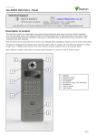
1
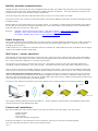
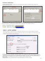
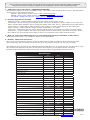
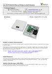
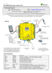
23/08/2012
Paxton
Ins-30075 Net2 nano control unit
Technical Support
[email protected]
01273 811011
Technical help is available:
Monday - Friday from 07:00 - 19:00 (GMT)
Saturday from 09:00 - 13:00 (GMT)
Documentation on all Paxton products can be found on our website - http://www.paxton.co.uk/
This access control unit uses wireless communication. It is recommended that a Net2Air
site surveyor is used to determine the best position for the bridge and control units.
This wireless unit requires a Net2Air bridge to communicate with the server PC.
Diagnostic LED's
12V DC
power supply
Net2 nano
Reader
Data/D0
Clock/D1
Media Detect
0V
Lock
123456
0889
0V
12V Lock
0V
Lock release
N.C.
N.O.
COM
Alarm
Entry
12V
Exit button
(push to make)
Green LED
Exit
Inputs
Contact
0V
Not connected
PSU/Tamper
*
12V
0V
Exit Button
*
12345126
Outputs
Green LED
Caution: For 12V DC readers only
Amber LED
http://paxton.info/107
Relay
12V
Red LED
Power
Reader/keypad
This is the heartbeat of the
system and should pulse
regularly. This indicates that
the processor is functioning.
Contact
0V
0V
Tamper
PSU
Net2Air wireless activity (Tx/Rx) - Blue
Door contact switch
(held closed by door)
Tamper switch
(optional)
A new unit requires approximately 30 seconds after initial power up to self configure.
During this time the OK LED will not be flashing.
The unit will not operate correctly until this function has completed.
LED indications
12V
Lock
Relay
Alarm
Exit
Contact
Tamper
PSU
Net2Air OK (Green)
(Orange)
(Orange)
(Red)
(Orange)
(Orange)
(Orange) (Orange)
(Blue)
(Green flash) -
Power LED
The 12V lock output is energised
The relay is energised - (N.O./COM contacts are closed)
12V Alarm output is active
The exit button contacts are closed
The door contacts are closed
The tamper contacts are closed
The PSU contacts are closed
Net2Air interface Tx/Rx activity
The internal software is running
Page 1
Net2Air wireless communication
Net2Air wireless control units are fully compatible with the hard wired Net2 range but there are several important
differences that need to be understood before installing wireless equipment. The most important of these is the
location of the control units and their bridge components.
These principles are therefore explained first before we move on to the control unit itself.
The access control unit connects to the Net2 system using Paxton Net2Air proprietary wireless technology through
a Net2Air bridge.
Radio signals do not always behave as you might expect. For example, a mobile phone that displays a full signal
on one part of the site will lose signal completely only a few metres away. These problems can be addressed by
using the Net2 site surveyor kit (690-200).
See also: XAN1095 - Net2 wireless access control - How does it work? < http://paxton.info/974 >
X
AN1096 - How to plan a Net2 wireless installation < http://paxton.info/975 >
X
Ins-30096 - Net2Air site surveyor < http://paxton.info/1015 >
Radio frequency
This product should not be installed within 3 metres of other wireless equipment operating on a 2.4Ghz frequency.
To ensure optimum performance other wireless networks should avoid WiFi channels 1, 2 and 3 to reduce the
possibility of interference.
A Net2 nano ACU or a Hands free interface cannot be installed in a Metal cabinet as this would block the RF signal
used for the Net2Air wireless technology.
Net2 nano / server operation
Data transfer with wireless technology requires far more control and error checking than with a hard wired data
line connection. Net2 classic runs with a server that originates and controls all the communications on the data
line. This would not be efficient in a wireless environment.
We therefore give the Nano controller the active role. Each Nano is always active and transmits data bursts
(including a regular Heartbeat) every few seconds. The Net2 server then acts upon these requests for service.
The PC requires at least one Net2Air bridge to communicate with a Nano. This can be a local Net2Air USB bridge
(only one per system) and/or multiple Net2Air Ethernet bridge units connected to the PC via a TCP/IP connection.
There is NO Net2 nano detection function. It is recognised that there could be security issues if the wireless
units were detectable from outside the site. During installation, a Nano unit binds to a Net2Air bridge which will
then only talk to registered units. The Server Configuration Utility also has an ' Enable commissioning' mode which
can be turned off to inhibit Nano units being added.
An entry is then made on the Doors screen and a special icon is used to denote the wireless connection.
Net2 Server
Reader
Control unit
The reader's default indication has all the LED's on. Access granted is denoted with a single flashing Green LED.
Access Denied is a single flashing Red LED.
Control unit installation
Wire the components to the Access Control Unit (ACU) as shown on the first page. This will include:
-
Reader/Keypad
Electric Lock
Power supply
Any other optional components
Press the exit button or in the absence of an exit button, short the 0V and exit terminals together.
The lock relay LED will come on and the lock should release.
Page 2
Software installation
The Net2 software should be loaded on the controlling PC and at least one Net2Air bridge configured to
communicate with the unit.
Only ONE Net2Air USB bridge may be used per system. Multiple Net2Air Ethernet bridges may also be configured.
Full documentation is supplied with the Net2Air bridge unit and also on the website as follows:
XAN1051 - Installing Net2 software < http://paxton.info/1520 >
XIns-30084 - Net2Air USB bridge < http://paxton.info/926 >
XIns-30085 - Net2Air Ethernet bridge < http://paxton.info/920 >
INPUT / OUTPUT WIRING
The Net2 nano has 3 outputs that can be configured in the Doors screen to perform different functions.
This flexibility means that a site that requires the Relay output (volt free contacts) for the door function can
configure the Lock output to drive a door bell.
Lock output - This is a transistor 'open drain' output, (not a voltage free contact) that has been designed
to simplify the wiring of the lock. It can be configured to operate in Fail lock, Fail unlock or toggle modes and
removes the need for additional links or diodes normally required when using a relay for output switching.
Relay output - This provides a set of volt free contacts to switch external devices.
Alarm output - This is a transistor driven output that switches to 0V when activated.
Page 3
Enrolling a Net2 nano
A Nano must bind to a Net2Air bridge before it will enrol itself onto the Net2 system. The term 'bind' is used to
denote the fixed relationship between a Nano and its bridge.
Create a user record in the database and assign a Net2 token to the user. If you are not using PROXIMITY tokens
you should still create the user record and assign a token number (Not a PIN) of your choice. These records can
be deleted after the installation is complete.
Connect a PROXIMITY reader to the Nano and then present the same user token previously assigned. (If you are
enrolling a Keypad only unit, enter the token number on the keypad followed by * ) The Nano will then transmit
the token number and wait for a response from a bridge.
If more than one bridge replies, the Nano checks the signal strength and selects the strongest bridge to
communicate with. The Net2 software confirms that the token number is in the database and if so registers this
Net2 nano/bridge binding.
Net2 nano reset
The Nano controller holds the address information for the bridge that it is bound with. This will cause problems if
the unit is to be used on another system.
To clear this address information, you need to perform a hardware reset. Link Orange/Mauve on the reader port
and then power cycle the unit.
Make sure that the power is not removed again until after the green OK LED is flashing again. Later versions of
software also flash the reader LED's until the reset process has finished. Remove the Orange/Mauve link.
PC Installation
The current specification for compatible PC hardware, network and operating systems is available on our website
at the following link: http://paxton.info/720
Software Configuration
Door name: Name the Door.
Door open time: Set the door open time.
Unlock the Door during: Holds the door unlocked during this
timezone. - Set to 'At No Time' for normal user operation.
Reader: Settings for the Reader and Keypad.
Outputs: Lock, Relay, Alarm. - Selects these outputs to be
used by the Lock, Bell or Alarm functions.
Alarm: Configures the settings for the different alarm types.
Codes: Valid keypad codes can be viewed, added and removed
(This tab is only displayed when a keypad is fitted)
Events: Shows the events for this control unit only.
Access Rights: Lists users who have access through this door.
Name: The reader can be named individually if required.
Reader type: Set the reader type, if applicable.
Keypad type: Set the keypad type, if applicable.
Reader operating mode: Set the operating mode.
Timed operating modes: A different operating
mode can be configured within a time window.
This product is not suitable for retail sale. All warranties are invalid if this product is not installed by a competent person.
Page 4
Here is the list of topics about this product that receive the most technical support enquiries.
We list them here to help you speed up the installation and trouble shooting process.
1 - ACU fails to enrol onto the PC (WIRELESS PROBLEMS).
QThe Net2 nano must be in range of a Net2Air bridge. This can be checked with a Site Surveyor. Detailed advice
Qcan be found on the website as follows:QXAN1095 - Net2 wireless access control < http://paxton.info/974 >
QXAN1096 - How to plan a Net2 wireless installation < http://paxton.info/975 >
QXIns-30096 - Net2Air site surveyor < http://paxton.info/1015 >
2QQQQ
QQQQ
Readers/keypads not working.
Software settings - Confirm that the settings of the reader or keypad are correct.
Connections - Check the wiring and integrity of the connectors. If possible, test this reader on the other unit.
Cable - Belden 9540 should be used to extend the reader cable (Max 100 m). Twisted pair alarm cable should
not be used. To confirm that a cable extention is not at fault, wire the reader directly to the reader port.
Supply voltage - Confirm that the voltage is within specification. (see table)
User token - Confirm that the user token used for testing is OK by presenting it to a known working reader.
Interference - Confirm whether the reader works when tested 'in hand' and not mounted on the wall. Ensure
that readers are not mounted back to back or there is no interference from other local RF devices.
3 - Why are some of the Net2 features (e.g. Fire alarm integration) not available on Net2 nano?
QWireless communication is not suitable for safety critical applications.
4 - Net2Air - What does this mean?
QThis is a term to describe the wireless communication protocol used by Paxton products in much the same
Qway as Bluetooth, but the Net2Air protocol is not open. Only Paxton products can use this technology.
QThe Net2Air protocol is based on the standard known as IEEE 802.15.4. It operates at 2.4 GHz and can co-exist
Qwith wireless LAN networks and other devices using this frequency such as DECT phones. All Paxton
Qproducts employ AES128 encryption technology to ensure that all communication remains secure.
Specifications
Features
Min
Max
Number of Cards
10,000
Number of PIN's
10,000
Access levels
250
Time zones
Maximum door open time
64
1 sec
99,999 sec
50
Number of Codes
Doors per ACU
1
Reader ports per ACU
1
Readers per port
2
Keypads per port
2
ACU's per Net2Air bridge - Recommended
Net2Air bridge per system
10
1
30 m
Net2Air wireless range
Data retention after total power loss
60 days
Events stored in ACU with no server connection
Electrical
Voltage
100
3,584
Min
Max
11V DC
14.5V DC
PCB Current (depending on activity)
120 mA
Relay switchable voltage
24V DC
Relay switchable current
2A
1.1 A
Dedicated lock output current
1A
Alarm output current
Reader port output current
500 mA
Carrier frequency
2.405 GHz
Min
Max
0 °C
+ 55 °C
Width
Height
Depth
Control Unit
105 mm
106 mm
23 mm
Plastic Housing
200 mm
200 mm
Environment
Operating temperature - Battery limits
No
Waterproof
Dimensions
The declaration of conformity is available on request. Contact details are provided at:
75 mm
http://paxton.info/596
Page 5