1
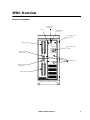
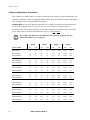
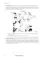
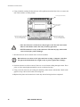
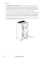
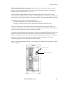
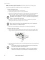
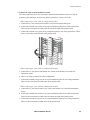
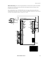
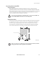
Stationary Power Distribution Unit (SPDU)
3-phase, 75-300 kVA
Installation Manual
APC’s Stationary Power Distribution Unit (SPDU) was designed for application in various 3-phase
environments. The SPDU can provide up to 11 sub-feed breakers, and offers the option of increasing
the number of panel boards by adding side cars. Top and bottom cable entry is standard. Other
features include total front accessibility, K1-K20 isolation transformers, and protective shielding.
Read this manual in its entirety before installing or operating the SPDU. Proper installation,
operation, and maintenance are necessary to ensure continued satisfactory performance from the
equipment. This unit was manufactured and tested in accordance with current industry standards.
SPDU Installation Manual
Contents
Safety . . . . . . . . . . . . . . . . . . . . . . . . . . . . . . . . . . . . . . . . . . . . 1
Safety warnings . . . . . . . . . . . . . . . . . . . . . . . . . . . . . . . . . . . . 1
Live maintenance precautions . . . . . . . . . . . . . . . . . . . . . . . . . . 1
SPDU Overview . . . . . . . . . . . . . . . . . . . . . . . . . . . . . . . . . . . . 2
External components . . . . . . . . . . . . . . . . . . . . . . . . . . . . . . . . 2
Internal components . . . . . . . . . . . . . . . . . . . . . . . . . . . . . . . . . 3
Custom configurations and options . . . . . . . . . . . . . . . . . . . . . . 4
Other SPDU features . . . . . . . . . . . . . . . . . . . . . . . . . . . . . . . . . 8
Receiving and Transporting . . . . . . . . . . . . . . . . . . . . . . . . . . . 9
Shipping . . . . . . . . . . . . . . . . . . . . . . . . . . . . . . . . . . . . . . . . . . 9
Receiving . . . . . . . . . . . . . . . . . . . . . . . . . . . . . . . . . . . . . . . . . 9
Transporting . . . . . . . . . . . . . . . . . . . . . . . . . . . . . . . . . . . . . . 10
Storage . . . . . . . . . . . . . . . . . . . . . . . . . . . . . . . . . . . . . . . . . . 10
Installation Considerations . . . . . . . . . . . . . . . . . . . . . . . . . . . 11
Site requirements . . . . . . . . . . . . . . . . . . . . . . . . . . . . . . . . . . 11
Required tools . . . . . . . . . . . . . . . . . . . . . . . . . . . . . . . . . . . . . 11
Clearances . . . . . . . . . . . . . . . . . . . . . . . . . . . . . . . . . . . . . . . 12
Placement . . . . . . . . . . . . . . . . . . . . . . . . . . . . . . . . . . . . . . . . 13
SPDU Installation . . . . . . . . . . . . . . . . . . . . . . . . . . . . . . . . . . 15
Accessing the SPDU . . . . . . . . . . . . . . . . . . . . . . . . . . . . . . . . 15
Wiring the SPDU . . . . . . . . . . . . . . . . . . . . . . . . . . . . . . . . . . . 17
Sidecar Installation . . . . . . . . . . . . . . . . . . . . . . . . . . . . . . . . . 26
Sidecar characteristics . . . . . . . . . . . . . . . . . . . . . . . . . . . . . . . 26
Connecting sidecars to the SPDU . . . . . . . . . . . . . . . . . . . . . . . 27
Connecting sidecars to sidecars . . . . . . . . . . . . . . . . . . . . . . . . 30
Appendix A: Electrical Checklist . . . . . . . . . . . . . . . . . . . . . . . 31
SPDU Installation Manual
1
Appendix B: Specifications/Data . . . . . . . . . . . . . . . . . . . . . . . 33
SPDU product specification . . . . . . . . . . . . . . . . . . . . . . . . . . . 33
SPDU with one sidecar . . . . . . . . . . . . . . . . . . . . . . . . . . . . . . 34
SPDU with two sidecars . . . . . . . . . . . . . . . . . . . . . . . . . . . . . . 35
Full load heat output (BTU/hr) . . . . . . . . . . . . . . . . . . . . . . . . . 36
Control fuses/supplementary protectors . . . . . . . . . . . . . . . . . . 36
Appendix C: Monitoring . . . . . . . . . . . . . . . . . . . . . . . . . . . . . 37
Basic monitoring . . . . . . . . . . . . . . . . . . . . . . . . . . . . . . . . . . . 37
Advanced or premium monitoring . . . . . . . . . . . . . . . . . . . . . . 37
Appendix D: Abbreviations and Acronyms . . . . . . . . . . . . . . . 38
Life Support Policy/Warranty . . . . . . . . . . . . . . . . . . . . . . . . . 42
Life support policy . . . . . . . . . . . . . . . . . . . . . . . . . . . . . . . . . . 42
Factory warranty . . . . . . . . . . . . . . . . . . . . . . . . . . . . . . . . . . . 43
APC Worldwide Customer Support . . . . . . . . . . . . . . . . . . . . . 44
2
SPDU Installation Manual
Safety
Safety warnings
• ONLY QUALIFIED PERSONNEL are permitted to perform any task or
function associated with the SPDU and its related equipment.
Warning
• This installation MUST COMPLY with the requirements of ANSI/NFPA 75
and NEC/NFPA 79 Art. 645.
• All safety codes, safety standards, and/or regulations must be strictly observed
during installation and ongoing maintenance of this equipment.
Electrical
Hazard
• Ensure that NO ELECTRICAL POWER SUPPLY is connected to the SPDU
and that ALL BREAKERS are in the OFF position before installing or
servicing the SPDU and any of its optionally ordered sidecars.
• All wiring instructions must be followed precisely. Failure to comply could
result in permanent damage to the equipment.
• The SPDU was designed to operate within its nameplate ratings. Operation
outside of these ratings may cause the equipment to fail.
• The SPDU contains several built-in safety features that are intended to reduce
hazards to operating personnel. UNDER NO CIRCUMSTANCES should any
safety feature be rendered inoperative.
Live maintenance precautions
APC does NOT recommend live maintenance of the SPDU. However, APC is aware that due to the
critical nature of data center loads, live maintenance may occur. If performing live maintenance,
observe the following precautions to reduce the risk of electric shock.
1. Never work alone.
Caution
2. Only a certified electrician who is trained in the hazards of live electrical
installation should perform the maintenance.
3. Know the procedure for disconnecting electricity to the SPDU and to the data
center in the event of an emergency.
4. Use rubber-insulated gloves and rubber-insulated boots.
5. Use double-insulated tools. If double-insulated tools are not available, insulate all
tools with electrical tape.
6. Use electrical tape to insulate any non-insulated conductive parts.
SPDU Installation Manual
1
SPDU Overview
External components
Reset/silence
push button
Horn
EPO (emergency
power off)
Monitoring screen
and controls
Upper panel board
Main input circuit
breaker
Upper panel board
breaker (225A)
Hinged panels (4)
Lower panel board
breaker (225A)
Lower panel board
SPDU Installation Manual
2
SPDU Overview
Internal components
Ventilation for transformer
Main cable
entry plate
Removable knockout plates
for incoming branch cable
Removable panel for 3-phase
and neutral bus connections
to sidecar (located on both
sides of SPDU)
Main input
circuit breaker
Provision for:
a) Two 42-pole panel boards
Cable clamps
b) One 42-pole panel board
and up to seven 225A
sub-feed breakers
c) One 42-pole panel board
and up to three 400A
sub-feed breakers
d) Up to eleven 225A
sub-feed breakers
Equipment
grounding busbar
Knockout plates
for cable entry/exit
Knockout for ground bus connection
to sidecar (located on both sides of
SPDU)
SPDU Installation Manual
Kick plate (also on rear of SPDU).
Remove for forklift access
3
SPDU Overview
Custom configurations and options
APC’s SPDUs are “built to order” as a means of satisfying each customer’s unique requirements. The
customer is thus able to select an appropriate SPDU model, along with whatever features and options
they would like to have incorporated into that model.
Product SKUs. A total of 21 SPDU product SKUs are available. The SKUs are broken down into
seven levels of output power (75, 100, 125, 150, 200, 225 or 300 kVA) and three types of
transformers (K1, K13 or K20). The first set of numbers appearing in the SKU refers to the output
power and the last set references the transformer type (i.e., PD125G6K13).
For weights and dimensions of SPDUs that have been pre-equipped with one
sidecar attachment, refer to page 34.
Note
Width
4
Depth
Height
Weight
Product SKU
IN
CM
IN
CM
IN
CM
LB
KG
PD75G6FK1
36
91
32
81
81.5
207
1270
576
PD75G6FK13
36
91
32
81
81.5
207
1320
599
PD75G6FK20
36
91
32
81
81.5
207
1340
608
PD100G6FK1
36
91
32
81
81.5
207
1525
692
PD100G6FK13
36
91
32
81
81.5
207
1550
703
PD100G6FK20
36
91
32
81
81.5
207
1695
769
PD125G6FK1
36
91
32
81
81.5
207
1555
705
PD125G6FK13
36
91
32
81
81.5
207
1600
725
PD125G6FK20
36
91
32
81
81.5
207
1715
778
PD150G6FK1
36
91
32
81
81.5
207
1590
721
PD150G6FK13
36
91
32
81
81.5
207
1700
771
PD150G6FK20
36
91
32
81
81.5
207
1960
889
PD200G6FK1
36
91
32
81
81.5
207
1900
862
PD200G6FK13
36
91
32
81
81.5
207
2100
953
PD200G6FK20
36
91
32
81
81.5
207
2100
953
PD225G6FK1
36
91
32
81
81.5
207
2100
953
PD225G6FK13
36
91
32
81
81.5
207
2300
1043
PD225G6FK20
36
91
38.5
98
81.5
207
2350
1066
PD300G6FK1
45
114
38.5
98
81.5
207
2300
1043
PD300G6FK13
45
114
38.5
98
81.5
207
2700
1225
PD300G6FK20
45
114
38.5
98
81.5
207
2900
1315
SPDU Installation Manual
SPDU Overview
Dual-feed main breakers. The SPDU can be equipped with any of five types of dual-feed main
breakers:
• 225A (p/n PDCBRF225)
• 400A (p/n PDCBRK400)
• 600A (p/n PDCBRL600)
• 800A (p/n PDCBRM800)
• 1200A (p/n PDCBRN1200)
Panel boards/sub-feed breakers. The SPDU can be equipped with any of the following
combinations of panel boards/sub-feed breakers:
• Two 42-pole panel boards (2 x p/n PDPNLPL1A)
• One 42-pole panel board and up to seven 225A sub-feed breakers (1 x p/n PDPNLPL1A and
7 x p/n PDCBRF225SF)
• One 42-pole panel board and up to three 400A sub-feed breakers (1 x p/n PDPNLPL1A and
3 x p/n PDCBRK400SF)
• Up to eleven 225A sub-feed breakers (11 x p/n PDCRBF225SF)
The terminology “up to...” refers to the maximum number of sub-feed breakers
available in that particular combination. Lesser numbers can also be provided.
Note
Sidecars. One or more sidecars (p/n PDSC100 for 75-225[K13] kVA units, and p/n PDSC300 for the
225[K20] unit and all 300kVA units) can optionally be attached to the main unit (via hard bus) to
increase the SPDU’s load distribution capability. The customer must also decide whether to add one
or two 42-pole panel boards (p/n PDPNLPL1A) to each optionally ordered sidecar. Sidecars can be
attached to either or both sides of the SPDU and daisy-chained, if necessary.
The number of sidecars that can be added to a single SPDU is limited only by the
size of the transformer and the maximum available current.
Note
Manual restart. Manual restart (p/n PDMRS100) is optionally available as an alternative means of
restarting the SPDU in the event input power is lost. The manual restart circuit automatically
energizes the shunt trip mechanism in the main input circuit breaker.
Transient voltage suppression system (TVSS). A transient voltage suppression system or TVSS
(various models are available) can be connected at either the input source or at the output from the
local panel boards. The TVSS protects the load by clipping voltage transients before they reach the
SPDU or the load.
Custom painting. While the standard SPDU color is basic black, the unit can optionally be painted
(p/n PDCP100) any other color.
SPDU Installation Manual
5
SPDU Overview
Floor jacks. A set of (four per unit) floor jacks (p/n PDFJ100) can optionally be applied to the
SPDU (and its attached sidecar(s)) to provide leveling and/or additional clearance for bottom cable
feed. The jacks are offered in heights of up to 18 inches, and are adjustable from one to three inches
above the base. Refer to the installation steps below.
Base Outline
Threads into
existing base
Level nut
Jam nut
Floor pedestals
available from
6.0 [15] X 12.0 [31]
6.0 SQ
[15]
UnitBase
baseOutline
outline
Unit
16.0
[41]
[406]
28.0
[71]
4.50
[11]
2.0
[5]
6.00
[15]
2.0
[5]
Pedestal footprint
0.75
[2]
INCHES [CM]
1. Screw pedestal assembly into bottom base and use jam nut to lock shaft into base. Ensure shaft is fully
engaged in base nut.
2. Lower pedestal to floor by rotating pedestal assembly using top nut.
3. Once levelled, secure to floor using 3/8” hardware in 9/16” diameter holes. Refer to drilling plan above.
Full-frame floor stand. A full-frame floor stand (p/n PDFS100 for 75-225[K13] kVA units, and p/
n PDFS130 for the 225[K20] unit and all 300 kVA units) can optionally be applied to the SPDU (and
each of its attached sidecar(s)) to provide leveling and bottom cable access independent of a raised
floor. The floor stand is constructed of welded steel, and is offered in heights of up to 32 inches (with
an adjustment range of +/- 3 inches).
6
SPDU Installation Manual
SPDU Overview
Seismic bracing. Seismic bracing (p/n PDSB100) is optionally available as a means of securing the
base frame of the SPDU (and sidecar) enclosure(s) to a concrete floor for those installations where
additional stability is either required or desired.
The diagram below shows the proper floor bracket placement and bolt locations for achieving
seismic bracing on the 75-225[K13] kVA enclosure. Contact APC for hardware and torque
specifications to meet various zone requirements. Seismic diagrams for the 225[K20] unit, the
300 kVA units, and each of the sidecar offerings are provided, as needed, with the Installation
Drawings.
42.75
[1085.85]
.375
[9.53]
5.07
[128.78]
2.00
[50.80]
20.10
[508.25]
5.00
[127.00]
5.38
[136.53]
.375
[9.53]
5.38
[136.53]
INCHES [MM]
SPDU Installation Manual
7
SPDU Overview
Monitoring. Three levels of SPDU monitoring are available:
• Basic (p/n PDBMN100). Continuously monitors the temperature of the transformer, the status
of the main input circuit breaker, and the status of a remote alarm contact. Local audio and
visual alarms are initiated when the core temperature of the transformer exceeds maximum
parameters. The main circuit breaker is then tripped or the remote alarm contact is closed.
• Advanced (p/n PDAMN100). Uses a microprocessor-based power monitor that is capable of
sensing, processing, and locally displaying information relating to output voltages for all three
phases of line-to-line and line-to-neutral circuitry; all three phases of output current, output
frequency and output power; as well as minimum and maximum acceptable values.
• Premium (p/n PDPMN100). Also uses a microprocessor-based power monitor capable of
sensing, processing, and displaying an extensive array of operational data. This level
additionally allows both local and remote access to information relating to output voltages for
all three phases of line-to-line and line-to-neutral circuitry; all three phases of output current,
output neutral, output ground, output frequency, and output power; as well as minimum and
maximum values, K factor, crest factor, discrete input and output status, analog input readings,
and any combination of up to seven metered values.
Note
• The above-described levels should NOT be considered the only options
available for SPDU monitoring. Various elements of each can be mixed and
matched to create the best-possible solution for each customer.
• Refer to “Appendix C: Monitoring” on page 37 for further information
regarding the functionality of SPDU monitoring options.
Other SPDU features
Emergency power off (EPO). The emergency power off (EPO) push button is located at the front
of the SPDU, beneath a protective cover. It is typically used in emergency situations to immediately
shut down the unit by disconnecting all power downstream of the main input circuit breaker.
Remote emergency power off (REPO). Remote emergency power off (REPO) can be
implemented at a location apart from the SPDU. When activated, it sends a command signal for the
SPDU to initiate an EPO condition.
8
SPDU Installation Manual
Receiving and Transporting
Shipping
Each SPDU (with up to one sidecar attachment) is shipped on its own pallet. Additional sidecars are
shipped two units to a pallet. For safety, pallets are slotted to allow forklift access from only one
direction. The enclosures are likewise designed to accommodate forklift movement.
To further stabilize the enclosures during shipping, (2) metal angle brackets connect the base of each
unit to its pallet. Packaging materials are employed to minimize the effects of impact.
Receiving
Check for damages.
1. Upon receipt, inspect the shipment for obvious signs of rough handling and/or external damage.
– DO NOT remove the packaging materials until the unit is off its pallet and ready for
installation.
– DO NOT remove the enclosure from its shipping pallet until all forklift movement is
completed.
– A thorough internal inspection should be conducted only after the enclosure has been
positioned for installation, and prior to making electrical connections.
2. Record any external and/or internal damage observed and call the carrier immediately to allow
their personnel to conduct an equipment inspection.
– DO NOT contact APC first — notify the carrier instead. Otherwise, APC may be unable to
assist in recovering the realized amount of the claim.
– All damage claims should be as specific as possible. Information pertaining to the shipment
should appear on the shipping label and related paperwork.
– BE SURE to request a copy of the carrier’s inspection report.
Check for discrepancies. The receiver should make certain the shipment has arrived in its entirety.
Compare information from the shipping label against what has actually been received. If anything is
missing, contact APC immediately (appropriate phone numbers are provided at rear of document).
SPDU Installation Manual
9
Receiving and Transporting
Transporting
Exercise caution. When transporting enclosures, try to avoid impact. Even the best packaging
cannot guarantee equipment protection. In addition, keep personnel clear of an enclosure in transport.
The units are heavy and can cause serious bodily injury.
For size and weight information, refer to “Product SKUs” on page 4 or “SPDU
with one sidecar” on page 34.
Note
Top box removal. Should the SPDU’s (and/or the sidecar’s) height exceed the doorway(s) by less
than 5.5 inches (14 cm), the unit’s Top Box can be removed to gain clearance. Using a large standard
screwdriver, detach the (4) silver ¼-20 x 6” bolts located at the overhead corner positions. Removing
the top box will reduce the unit’s height to 76 inches (193 cm). Once the SPDU (or sidecar) is in
position and cleared of all doorways, re-attach the top box using the same four bolts.
REAR of enclosure
Silver BOLT
Ventilation screen
Silver BOLTS
Top Box
Main cable
entry plate
Knockout
plates (5)
Silver BOLT
FRONT of enclosure
Storage
The SPDU is not suited for outdoor storage, and the equipment warranty may not be applicable under
such circumstances. If the equipment must be stored, it should be stored indoors and with its
protective packaging still in place.
• The equipment should be kept in a climate-controlled environment with a temperature range of
0° to 40°C (32° to 104°F) and a relative humidity of 0% to 95%, non-condensing.
• The equipment must be protected at all times from excessive moisture, construction dirt,
corrosive elements, and other contaminants. The enclosure (still on its pallet, if possible) should
be set on a firm and level surface.
• Make sure the equipment does not exceed floor loading requirements. For size and weight
information, refer to “Product SKUs” on page 4 or “SPDU with one sidecar” on page 34.
• DO NOT, under any circumstances, stack other equipment on top of the enclosure.
10
SPDU Installation Manual
Installation Considerations
Site requirements
• The equipment should be kept in a climate-controlled environment with a temperature range of
0° to 40°C (32° to 104°F) and a relative humidity of 0% to 95%, non-condensing.
• The equipment must be protected at all times from excessive moisture, construction dirt,
corrosive elements, and other contaminants.
• Make sure the floor’s surface is firm and level, and equipment does not exceed floor loading
requirements. For size and weight information, refer to “Product SKUs” on page 4, “SPDU with
one sidecar” on page 34, or “SPDU with two sidecars” on page 35.
Required tools
The following tools are required for installation of the SPDU and its sidecars (if employed):
• Ratchet set w/sockets
• Open end/box wrenches
• Torque wrench
• Standard screwdrivers (small and large)
• Phillips screwdrivers
• Wire stripper
When performing “live maintenance” always use double-insulated tools. If doubleinsulated tools are not available, insulate all tools with electrical tape.
Caution
SPDU Installation Manual
11
Installation Considerations
Clearances
When placing the SPDU (and sidecars, if used) for installation, make certain each enclosure adheres
to the following recommendations:
• A FRONT clearance of at least thirty-six inches (36”) is recommended for front-access
servicing.
• A TOP clearance of at least eighteen inches (18”) supports ventilation.
• A BOTTOM clearance of at least six inches (6”) is recommended for accessing cables and
enhancing ventilation (refer to graphic on page 13 for typical raised floor cutout dimensions).
• There are no special requirements for REAR clearance.
• Local and national codes supersede recommended levels of clearance.
Note
• If the floor is not raised or fails to meet bottom clearance criteria, optional
floor jacks or a full-frame floor stand (both described on page 6) may be used.
18.00
[46]
6.00
[15.24]
36.00
[92]
12
SPDU Installation Manual
INCHES [CM]
Installation Considerations
Placement
Follow these instructions when placing enclosures:
1. Decide where the enclosure(s) will be placed and prepare the appropriate floor cutout(s), if
necessary. Floor jacks or a full-frame floor stand (both are described on page 6) might
optionally be used to attain recommended bottom clearance.
The cutout for the 75-225[K13] kVA SPDUs is shown below. The cutout for the 225[K20]
SPDU and the 300 kVA SPDUs is provided, as needed, with the Installation Drawings.
4.00
[10]
32.00
[81]
Cutout area for cable
entry and ventilation
27.00
[69]
FRONT
7.00
[18]
22.00
[56]
36.00
[91]
INCHES [CM]
Make certain cutouts do not compromise the structural integrity of the floor, and
that loading requirements remain acceptable to the installation.
Note
2. Set the pallet containing the enclosure(s) on a firm and level surface as close as possible to the
unit’s final installation location.
3. Remove the packaging material.
4. Using a ratchet and socket, remove the (2) metal angle brackets securing the base of the
enclosure(s) to the pallet.
5. Use a Phillips screwdriver to remove both front and back kick plates. Refer to “Internal
components” on page 3 for location of kick plates.
SPDU Installation Manual
13
Installation Considerations
6. Using a forklift, carefully lift the enclosure off its pallet and onto the floor. Now on casters, the
unit can be rolled to its final position.
Leveling feet (4 locations)
BOTTOM of enclosure
Removable connector plate
- 32 x 1/2” conduit positions
- 6 x 1/2-3/4” conduit positions
Swivel casters
(4 locations)
Removable connector plate
- 38 x 1/2” conduit positions
- 6 x 1/2-3/4” conduit positions
• Once the enclosure is on the floor, it may begin to roll. The unit’s movement
must be controlled to ensure the safety of nearby personnel.
Caution
• NEVER stand on or in any of the enclosures. The unit may tip, which could
cause serious injury and/or damages.
7. Roll the enclosure to the location where it will be installed.
Roll enclosure over sheets of 3/4” plywood when crossing a computer room floor.
The plywood will distribute the weight evenly to protect against floor damage.
Note
8. Position enclosure over floor cutouts. Take care to avoid casters falling through cutouts. Floor
jacks or a floor stand might optionally be used, as indicated in step 1.
9. Using a wrench, lower the (4) leveling feet until they make contact with the floor. Refer to the
graphic in step 6 above for location of leveling feet.
10.Replace kick plates at front and rear of unit only after all wiring has been completed.
14
SPDU Installation Manual
SPDU Installation
• Ensure that NO ELECTRICAL POWER SUPPLY is connected and that ALL
BREAKERS are in the OFF position before installing the SPDU.
• ALL WIRING INSTRUCTIONS must be followed precisely. Failure to comply
could result in permanent damage to the equipment.
Electrical
Hazard
Accessing the SPDU
Front doors.
• A handle mechanism interlocks the two front doors of the enclosure. Front door keys are
tie-wrapped to the protective cover of the EPO button.
To open the front doors:
1. Pull down the bottom part of the
mechanism to expose the metal lock slot.
Handle
2. Insert front door key into metal lock and
make a one-quarter turn to the right. This
will release the handle.
3. Move the handle to either side to open
door.
Metal Lock
• The front doors can be removed by: a.) opening each door in turn, b.) removing its hinge pin,
and c.) lifting the door away from the hinge. Once doors have been removed, make sure the
hinge pins are stored in a safe place for later use.
• The removed front doors must be restored prior to placing the SPDU into service.
Hinged panels. Behind the front door are four hinged panels. Each panel can be opened by
loosening its top and bottom turn screws, and then re-secured by tightening these same screws.
Knockouts.
• On top of the SPDU are six (6) removable plates: five (5) knockout plates for output cables and
one (1) main input cable entry plate. All are held in place with 10-32 x ¾” captive screws.
To avoid cable congestion and facilitate future loads, top knockouts nearest the
front and center of the enclosure should be utilized first.
Note
SPDU Installation Manual
15
SPDU Installation
• At the bottom of the SPDU are two (2) removable plates. These contain knockouts for
connecting cables to the panel board and/or sub-feed breakers. Refer to “Internal components”
on page 3 and the step 6 graphic on page 14.
Power cables MUST NOT run near any control wiring. Leave a minimum 1”
clearance between cables and wires.
Caution
• The final arrangement of knockouts will correspond to the customer’s chosen configuration.
Removing trim. The sub-feed breaker trims are located behind the front doors.
To remove trim:
• Squeeze the upper and lower levers together.
• Turn inward, release, and lock in place.
• Pull the trim toward you.
Levers
LLevers
To restore trim:
• Slot the movable trim into the stationary
trim.
• Squeeze the upper and lower levers together.
• Turn outward and release.
• The hinge pins should spring back into
place.
• Before removing trim, disconnect the ground straps. Store trim in a safe area
to prevent injury to personnel or damage to the SPDU.
Note
16
• Trim must be restored and ground straps reconnected prior to placing the
SPDU into service.
SPDU Installation Manual
SPDU Installation
Wiring the SPDU
Wiring considerations.
• Because all electrical and mechanical connections can be accessed from the front of the SPDU,
junction boxes are not required. A dedicated feeder should provide the necessary 3-phase input
power to the unit.
• Conductors are coded as follows:
Conductor
Code
Phase A
L1
Phase B
L2
Phase C
L3
Ground
Green
Neutral
White
• Those circuits connected to the SPDU distribution breakers should be configured so that the
load is equally balanced across the three phases.
• All conductors must comply with NEC and other applicable codes. Refer to the table below for
typical conductor sizes, and then refer to “Torque values” on page 19. Conductor sizes relate to
NEC 1996 Table 310-16 using 75° copper conductors. Recommended torque values should be
used unless otherwise specified.
Units with transformers
Input
Units without transformers
Input
Main
Suggested wire
Input
Main
Suggested wire
volts
kVA
FLA*
breaker
size (AWG)
FLA*
breaker
size (AWG)
208
75
208
250A
250 MCM
208
250A
250 MCM
100
278
350A
500 MCM
278
350A
500 MCM
125
347
450A
(2) 4/0
347
450A
(2) 4/0
150
416
600A
(2) 350 MCM
416
600A
(2) 350 MCM
75
180
225A
4/0
N/A
N/A
N/A
100
241
300A
350 MCM
N/A
N/A
N/A
125
301
400A
(2) 4/0
N/A
N/A
N/A
150
361
450A
(2) 4/0
N/A
N/A
N/A
75
114
150A
1/0
114
150A
1/0
100
152
200A
3/0
152
200A
3/0
125
190
250A
250 MCM
190
250A
250 MCM
150
228
300A
350 MCM
228
300A
350 MCM
200
304
400A
(2) 4/0
304
400A
(2) 4/0
225
342
450A
(2) 4/0
342
450A
(2) 4/0
240
380
SPDU Installation Manual
17
SPDU Installation
Units with transformers
Input
Input
Main
Suggested wire
Input
Main
Suggested wire
volts
kVA
FLA*
breaker
size (AWG)
FLA*
breaker
size (AWG)
400
75
108
150A
1/0
108
150A
1/0
100
144
200A
3/0
144
200A
3/0
125
180
225A
4/0
180
225A
4/0
150
217
300A
350 MCM
217
300A
350 MCM
200
289
400A
(2) 4/0
289
400A
(2) 4/0
225
325
400A
(2) 4/0
325
400A
(2) 4/0
75
104
150A
1/0
104
150A
1/0
100
139
175A
3/0
139
175A
3/0
125
174
225A
4/0
174
225A
4/0
150
209
300A
350 MCM
209
300A
350 MCM
200
278
400A
(2) 4/0
278
400A
(2) 4/0
225
313
400A
(2) 4/0
313
400A
(2) 4/0
75
90
125A
1
N/A
N/A
N/A
100
120
150A
1/0
N/A
N/A
N/A
125
150
200A
3/0
N/A
N/A
N/A
150
180
225A
4/0
N/A
N/A
N/A
200
241
300A
350 MCM
N/A
N/A
N/A
225
271
350A
500 MCM
N/A
N/A
N/A
300
361
450A
(2) 4/0
N/A
N/A
N/A
75
72
90A
3
N/A
N/A
N/A
100
96
125A
1
N/A
N/A
N/A
125
120
150A
1/0
N/A
N/A
N/A
150
144
200A
3/0
N/A
N/A
N/A
200
192
250A
250 MCM
N/A
N/A
N/A
225
241
300A
350 MCM
N/A
N/A
N/A
300
289
400A
(2) 4/0
N/A
N/A
N/A
415
480
600
* FLA = Full load amps
18
Units without transformers
SPDU Installation Manual
SPDU Installation
Torque values. Because various types of breakers are used in these assemblies, consult the breaker
nameplate for actual torque values based on wire sizes.
• Main and sub-feed breakers (in-lbs):
Wire
size
AWG
No. of
wires
Slotted head screw
Socket head screw
Over 1/4” slot length
1/4” & less slot length
14-10
1
35
20
8
1
40
25
6
1
45
4
1
3
3/16” socket
5/32” socket
35
120
100
45
35
120
100
1
50
35
120
100
2
1
50
40
120
100
1
1
50
120
100
1/0
1
50
120
100
2/0
1
50
120
100
3/0
1
50
120
100
4/0
1
50
120
100
• Panel board breakers (in-lbs):
Wire size AWG
No. of wires
Torque (in-lbs)
14 - 10
1
20
8
1
25
6-4
1
27
3 - 1/0
1
45
SPDU Installation Manual
19
SPDU Installation
Grounding electrode conductor (GEC). Prior to making any electrical wiring connections, a
grounding electrode conductor (GEC) must be connected from the SPDU’s main ground busbar to
the facility’s grounding electrode. NEC Table 250-66 provides recommended GEC sizing based on
your SPDU’s operational capacity. While conduit is not a requirement, the GEC connection must be
protected from damage. A cable tray, raceway, or cable sheath are alternative safeguards.
The GEC connection to the SPDU’s main ground busbar is accomplished with a (provided) box type
wire connector. The GEC connection to the facility’s grounding electrode can be made by exothermic
welding, listed lugs, listed pressure connectors or some other NEC-specified means. Regardless of
the method used, the GEC connection must be made in a manner that is both permanent and effective.
The main ground busbar in the SPDU is located in the lower-right corner of the enclosure (when
facing the unit). See graphic below for the exact location.
GEC connection to
main ground
20
SPDU Installation Manual
SPDU Installation
SPDU (and sidecar) input connections. Input connections are made to the three termination
points at the top of each input breaker (main circuit breaker, panel board breakers, and sub-feed
breakers) in phase sequence A-B-C (L1, L2, L3).
For those SPDUs equipped WITH a transformer, the main input feeder consists of the 3-phase
conductors and one ground conductor (3W+G). For SPDUs WITHOUT a transformer, the main input
feeder consists of the 3-phase conductors, one neutral conductor, and one ground conductor (4W+G).
Conductors to the main input circuit breaker should enter:
• through the main plate on top of the SPDU (for top entry), or
• through a removable connector plate at the bottom of the SPDU (for bottom entry).
The A-B-C connections are made left-to-right to the positions shown in the graphic below. The
Ground connection (green) goes to the vertical bar on the FAR left side of the breaker. The Neutral
connection (white) goes to the vertical bar nearer to the breaker.
Conductors to the panel board and sub-feed breakers should enter through knockouts in the connector
plates at the bottom of the enclosure. Both of these breaker types have been rotated 90° counter
clockwise, and therefore the A-B-C connections on them are made from top-to-bottom. The Neutral
connection (white) goes to the vertical bar on the FAR left side of the breaker. The Ground
connection (green) goes to the vertical bar nearer to the breaker.
Refer to “Wiring considerations” on page 17 for conductor size, and then refer to appropriate “Torque
values” on page 19.
FRONT
Input power connections
Main input circuit breaker
FRONT
SPDU Installation Manual
21
SPDU Installation
SPDU (and sidecar) output connections. The following instructions for making output
connections are applicable to the SPDU and each of its attached sidecars.
1. Install a distribution breaker
a. Unlock and open the front door(s) of the enclosure.
b. Open the hinged panel(s) to gain access to the panel boards.
c. Select the next available breaker position(s) in either the upper or lower panel board, then
snap the new single-, double-, or triple-pole breaker into the appropriate guard rail.
Note
The top pole of a triple-pole breaker must always be placed in an L1 position on the
panel board. These are positions 1, 7, 13, 19, etc. on the left side and positions 2, 8,
14, 20, etc. on the right side of the board.
d. Make bolt-on connections, if required (some breakers are simplified snap-in models,
negating the need for this step). Torque screws to 25 in-lbs.
There is one bolt-on connection for a single-pole breaker, two for a double-pole
breaker, and three for a triple-pole breaker.
Note
e. Remove the corresponding plastic blanking plate on the appropriate hinged panel.
2. Install an output cable (or whip)
a. Attach a strain relief connector bushing to the cable as shown in the below graphic. Slide
enough cable through the strain relief connector to reach the intended distribution breaker.
b. Apply the strain relief connector to the next available knockout on the roof of the cabinet and
tighten in place.
• To avoid cable congestion, start with the knockouts located toward the front
and center of the enclosure and work outward.
Note
22
• If the cable is thicker than the standard 3/4” size, use a Greenlee punch (or
equivalent) to enlarge the size of the knockout. Use appropriate hardware.
SPDU Installation Manual
SPDU Installation
3. Connect the cable to the distribution breaker
The cable’s individual wires are connected to the distribution breaker’s bolt-on or snap-in
position(s); the neutral bar, if necessary; and the ground bar. Torque to 25 in-lbs.
– When connecting a 3-wire cable to a single-pole breaker:
a. Connect the L1 wire (black) to the breaker’s one load-side termination point.
b. Connect the Neutral wire (white) to any open termination point on one of the neutral bars.
These are the vertical bars located to the far left and far right of the panel boards.
c. Connect the Ground wire (green) to any termination point on one of the ground bars. These
are the vertical bars located nearer to the panel boards.
N
G
– When connecting a 3-wire cable to a double-pole breaker:
a. Connect the L1 wire (black) and Neutral wire (white) to the breaker’s two load-side
termination points.
b. There is no Neutral connection in this configuration.
c. Connect the Ground wire (green) to any open termination point on one of the ground bars.
These are the vertical bars located nearer to the panel boards.
– When connecting a 4-wire cable to a double-pole breaker:
a. Connect the L1 wire (black) and L2 wire (red) to the breaker’s two load-side termination
points.
b. Connect the Neutral wire (white) to any open termination point on one of the neutral bars.
These are the vertical bars located to the far left and far right of the panel boards.
c. Connect the Ground wire (green) to any open termination point on one of the ground bars.
These are the vertical bars located nearer to the panel boards.
SPDU Installation Manual
23
SPDU Installation
– When connecting a 4-wire cable to a triple-pole breaker:
a. Connect the L1 wire (black), L2 wire (red), and Neutral wire (white) to the breaker’s three
load-side termination points.
b. There is no Neutral connection in this configuration.
c. Connect the Ground wire (green) to any open termination point on one of the ground bars.
These are the vertical bars located nearer to the panel boards.
– When connecting a 5-wire cable to a triple-pole breaker:
a. Connect the L1 wire (black), L2 wire (red), and L3 wire (orange) to the breaker’s three
load-side termination points.
b. Connect the Neutral wire (white) to any open termination point on one of the neutral bars.
These are the vertical bars located to the far left and far right of the panel boards.
c. Connect the Ground wire (green) to any open termination point on one of the ground bars.
These are the vertical bars located nearer to the panel boards.
N
24
G
SPDU Installation Manual
SPDU Installation
SPDU control wiring. The control wiring terminal block is located near the top frame of the SPDU,
directly above the main input circuit breaker. Refer to the diagram below for the proper wiring
termination points in the block.
The recommended wire type is TEW/TW/MTW, with a size range of from #20-14 AWG. Strip
enough insulation from each wire to achieve connection to the SPDU terminal block, then secure the
wire with a small standard screwdriver. Torque to 4.5-6 in-lbs.
L1A
T2
250VA
480/24
PDU CONTROLLER BOARD
#16 RED
H1
X1
480V
24V
1
XFMR
FU3/12A
H3
X2
REPO
ALARM
SI
X2
NET-18
2
2
3
3
4
4
5
5
6
6
7
7
8
8
SUMMARY
ALARM
RE1
0V
GRD
#16 WHITE/YELLOW
GRD
P2
NET-1
1
L2A
EPO
P1
9
SUMMARY
ALARM
RE3
NET-9
SUMMARY
ALARM
RE5
ALARM
RE2
HORN
RE4
SHUTDOWN
RE6
9
17
8
16
7
15
6
14
5
13
4
12
3
11
2
NET-10
TB11(12)
X1
A
X2
TB11(11)
ALM 1
TB11(12)
L1
L2
ALM 1
2900 Hz
TB11(11)
CB1
SHUNT TRIP
A
B
1
#16 WH/BLK
P4
P3
1
ICOM
CB1 MBA
TB11(10)
3
3
ALARM 3
4
4
ALARM 2
5
5
ALARM 1
6
6
7
7
8
8
REPO 2
9
9
REPO 1
10
10
11
11
12
12
4
3
13
13
2
1
14
14
15
15
5
ON
8
SILENCE
3
TB11(12)
7
6
9
T1 180o Therm
3
2
SW1
4
T1 200o Therm
3
1
2
8
EPO
3
1
P4 ARE
DRY
CONTACTS
ONLY
REPO 3
ICOM
TB11(13)
INC
POWER
2
ALARM 4
ICOM
TB11(10)
2
1
DEFAULT
SWITCH
SETTINGS
4
SW1 SETTINGS
SPDU Installation Manual
SW
Designation
ON
8
7
Manual Restart
Enabled
Disabled
OFF
REPO #3
N.C. INPUT
N.O. INPUT
6
5
REPO #2
N.C. INPUT
N.O. INPUT
REPO #1
N.C. INPUT
N.O. INPUT
4
ALARM #4
SHUTDOWN
ALARM
3
2
ALARM #3
SHUTDOWN
ALARM
ALARM #2
SHUTDOWN
ALARM
1
ALARM #1
SHUTDOWN
ALARM
25
Sidecar Installation
Sidecar characteristics
The SPDU’s load distribution capability can be increased through the addition (attachment) of
optionally ordered sidecars. At the customer’s discretion, each sidecar can be equipped with either
one or two 42-pole panel boards. Sidecars can be connected (via busbar) to either side of the SPDU
and daisy chained, if necessary. Like the SPDU, the sidecar offers top and bottom knockout plates to
accommodate incoming cables.
Sidecars for the 75-225[K13] kVA units measure 20” W x 32”D x 81.5”H [51 cm x 81 cm x 207 cm]
and weigh 520 lbs [254 kg]. Sidecars for the 225[K20] unit and all 300 kVA units measure
20”
W x 38.5”D x 81.5”H [51 cm x 98 cm x 207 cm] and weigh 590 lbs [268 kg].
The 5.5-inch [14 cm] top box can be removed to reduce the unit’s height during transport to 76”
[193 cm]. Refer to “Top box removal” on page 10.
Knockouts for
top-exit cables
Busbar connectors to
SPDU (3-phase & neutral)
Ground bus
Plate removed to facilitate
top exit of cables
Neutral bus
Sidecar shown with
door closed
Circuit breakers
Neutral bus
Ground bus
Knockout for ground bus
connection to SPDU
Remove trim plates to
facilitate bottom wiring
Bottom kick plate removed
SPDU Installation Manual
Bottom kick plate
26
Sidecar Installation
Connecting sidecars to the SPDU
General information.
• When shipped mechanically assembled to the SPDU, the sidecar is already electrically
connected (via busbar) as well. The busbar connections accommodate both power and ground.
• When shipped separately, the sidecar contains splice kits and mounting hardware for connecting
its busbar to the busbar in the SPDU. The following procedure describes how to connect a
sidecar to the SPDU (WITH or WITHOUT transformer).
Electrical
Hazard
Ensure that NO ELECTRICAL POWER SUPPLY is connected to the SPDU, and
that ALL BREAKERS in both units are in the OFF position.
Step-by-step procedure.
1. Decide where the sidecar will be placed in relation to the SPDU (left or right side) and prepare
the appropriate floor cutout(s), if necessary. Floor jacks or a full-frame floor stand (both are
described on page 6) might optionally be used to attain recommended bottom clearance.
The cutout for the 75-225[K13] kVA sidecars is shown below. The cutout for the 225[K20]
sidecar and all 300 kVA sidecars is provided, as needed, with the Installation Drawings.
20.00
[51]
32.00
[81]
Cutout area for cable entry
14.00
[36]
1.00
[2.5]
13.25
[34]
FRONT
3.00
[7.6]
INCHES [CM]
Make sure cutouts do not compromise the structural integrity of the floor, and that
loading requirements remain acceptable to the installation.
Note
SPDU Installation Manual
27
Sidecar Installation
2. Open the front door of the sidecar using the same procedure outlined in “Front doors” on
page 15. Behind the front door is one large hinged panel that is opened by loosening its top and
bottom turn screws. Retrieve the busbar splice plates and hardware inside the unit.
3. Using a Phillips screwdriver, remove a) the adjacent side panel on the SPDU; and b.) both side
panels on the sidecar. The latter action will permit better access for accomplishing the busbar
connections described later.
4. Place the sidecar in close proximity to where it will be attached to the SPDU. Take care to avoid
casters falling through the floor cutout.
5. Adjust the sidecar’s height to match the height of the SPDU. This is accomplished by either
extending or extracting the leveling feet (or adjusting the floor jacks or floor stand).
6. Align the (8) facing assembly holes on the side of the sidecar with the (8) facing assembly holes
on the side of the SPDU.
7. Using a wrench, thread (8) 5/15 x 3/4” bolts through the sidecar’s holes to pre-set weld nuts
located in the SPDU’s holes. Bind until rigid.
8. Position the (4) busbar splice plates (3-phase power and neutral) between the (4) busbar strips
protruding through the open side panels of both the SPDU and the sidecar.
Phase A, B, C and neutral splice to SPDU
or another sidecar (busbar strips available
on both sides to accommodate either left
or right connection).
Ground bus splice to SPDU or another
sidecar (ground available on both sides
to accommodate either left or right
connection).
9. Using a wrench, thread (4) 1/4 x 20 x 1” bolts through each splice plate and into pre-set press
nuts in the busbar protruding from both enclosures. Torque to 11 ft-lbs.
10.Reinstall the sidecar’s external side panel.
28
SPDU Installation Manual
Sidecar Installation
11.Connect the ground busbar (refer to “Internal components” on page 3 and the step 8 graphic on
page 28 for location of ground bus) using the (2) angled splice plates. Three 1/4 x 20 x 1” bolts
are required. Torque to 6 ft-lbs.
SPDU
SIDECAR
Cabinet walls
Existing sidecar bus
Existing SPDU bus
Ground bus splice
(C/W 5/16” hardware supplied)
12.Reinstall the sidecar’s external side panel.
SPDU Installation Manual
29
Sidecar Installation
Connecting sidecars to sidecars
Electrical
Hazard
Ensure that NO ELECTRICAL POWER SUPPLY is connected to the SPDU, and
that ALL BREAKERS in both units are in the OFF position.
Step-by-step procedure. The procedure for connecting sidecars to sidecars (in a daisy chained
alignment) is very similar to the procedure for connecting sidecars to the SPDU. Refer to the
diagrams in the previous section for any visual support required.
1. Depending on where each sidecar will be positioned in relation to the SPDU, prepare the
appropriate floor cutouts (if necessary) as per the step 1 graphic on page 27. Floor jacks or a
full-frame floor stand (both are described on page 6) might be used to attain bottom clearance.
Make certain cutouts do not compromise the structural integrity of the floor, and
that loading requirements remain acceptable to the installation.
Note
2. Open the front door of the add-on sidecar using the same procedure outlined in “Front doors” on
page 15. Behind the front door is one large hinged panel that is opened by loosening its top and
bottom turn screws. Retrieve the busbar splice plates and hardware inside the unit.
3. Using a Phillips screwdriver, remove a) the exposed side panel of the previously installed
sidecar; and b) both side panels on the add-on sidecar. The latter action will permit better access
for accomplishing the busbar connections described later.
4. Place the add-on sidecar in close proximity to where it will be attached to the previously
installed sidecar. Take care to avoid casters falling through the floor cutout.
5. Adjust the add-on sidecar’s height to match the height of the other sidecar. This is accomplished
by extending or extracting the leveling feet (or adjusting the floor jacks or floor stand).
6. Align the (8) facing assembly holes on the side of the add-on sidecar with the (8) facing
assembly holes on the side of the previously installed sidecar.
7. Bind the sides of the two sidecars rigidly together using a wrench with (8) 5/16 x 1.25 hex bolts,
(16) 5/16 washers and (8) 5/16 hex nuts.
8. Position the (4) busbar splice plates (3-phase power and neutral) between the (4) busbar strips
protruding through the open side panels of both sidecars.
9. Using a wrench, thread (4) 1/4 x 20 x 1” bolts through each splice plate and into pre-set press
nuts in the busbar protruding from both enclosures. Torque to 11 ft-lbs.
10.Connect the ground busbar (refer to step 10 on page 29) using the (2) angled splice plates.
Three 1/4 x 20 x 1” bolts are required. Torque to 6 ft-lbs.
11.Reinstall the add-on sidecar’s external side panel.
30
SPDU Installation Manual
Appendix A: Electrical Checklist
• ONLY QUALIFIED PERSONNEL are permitted to perform any task or
function associated with this equipment!
Electrical
Hazard
• Ensure that NO ELECTRICAL POWER SUPPLY is connected and that ALL
BREAKERS are in the OFF position before installing or servicing the SPDU!
1. Confirm that clearances for cabling, service access and ventilation correspond to
specifications. There should be a minimum of 18” ABOVE the unit, 6” BELOW
it, and 36” in FRONT.
2. Remove front doors and interior trims as required. Note that panel on side of
enclosure facilitates manufacturing and should NOT have to be removed during
SPDU installation. All ground straps must be disconnected from trims prior to
removing them from enclosure.
3. Confirm that all main, secondary, and branch circuit breakers are in the ‘OFF’
position.
4. Inspect all wire and conductor insulation for damage.
5. Check all transformer and breaker connections for tightness, and re-torque if
necessary.
6. Check all terminal block connections for tightness, and re-torque if necessary.
7. Verify that all cables meet or exceed specified conductor sizes.
8. Remove all foreign objects from interior of SPDU. The intake and exhaust air
screens must be clean and clear of obstruction. Air passages above, below and
behind power transformer must likewise be clear of obstruction.
9. Ensure floor cutouts correspond to the step 1 graphic on page 13, the step 1
graphic on page 27, or as specified in the Installation Drawings.
10.Verify input connections to main circuit breaker, equipment grounding, and
grounding of electrode conductors.
11.Turn ON utility-supplied input power to the SPDU.
12.Check phase rotation on main input circuit breaker. Phase rotation should be A,
B, C, left-to-right.
SPDU Installation Manual
31
Appendix A: Electrical Checklist
13.Verify and record INPUT voltages on the main input circuit breaker.
a. Volts, Phase A-B:
b. Volts, Phase B-C:
c. Volts, Phase C-A:
d. Volts, Phase A-N:
e. Volts, Phase B-N:
f. Volts, Phase C-N:
14.If input voltage is incorrect, check for wiring errors or improper transformer tap
upstream of the SPDU.
15.If main input breaker trips within (1) minute of turn on, contact APC Services or
a factory rep for assistance. Check phase rotation (on line side of terminals) in
each panel board’s main breaker and sub-feed breakers. Rotation should be A, B,
C, top-to-bottom. Note that main panel breaker and sub-feed breakers have been
rotated 90 degrees, counter-clockwise.
16.Check Alarm circuitry by placing a jumper between terminals TB1-2 and TB113 in the control section above the main breaker. Horn will sound, pilot light
illuminate, summary alarm K2, and control relay K1 energize. Press the Silence
Push button to de-activate the Horn, though the alarm will remain lit. Remove
the jumper and the alarm will automatically reset.
17.Check EPO / 200°C Transformer thermal trip circuits by placing a jumper
between terminals TB1-2 and TB1-8 in control section. This energizes main
breaker’s shunt trip, tripping the breaker. Horn will sound, pilot light illuminate,
summary alarm K2 and control relay K1 energize. Remove the jumper and the
alarm will clear. Reset breaker and REPEAT test by depressing local EPO push
button. REPEAT for each remote EPO in the system. Note the control circuit
will be energized, even though main breaker is in the trip or off position.
18.Check Manual Restart (if supplied) by placing selector switch on control panel
in the ON position. De-energize control circuitry by removing Fuse FU3. Upon
detecting a power failure, the shunt trip in the main breaker energizes and trips
the breaker. Replace the fuse and put selector switch in position that matches
customer requirements.
19.If a Normally Closed Remote Emergency Power Off (REPO) is used, remove
the jumper between TB1-23 and TB1-24. Wire dry contacts from REPO circuits
to these terminals. Depress remote push button. Control relays K3 and K4 will
de-energize, activating the shunt trip and tripping the main breaker. Reset
breaker and test for each REPO in the system.
32
SPDU Installation Manual
Appendix B: Specifications/Data
SPDU product specification
Input
Rated Power kVA:
Output
75, 100, 125, 150, 200, 225, Nominal Output
300
Voltage:
208V/120V
Nominal Input
Voltage:
60 Hz @ 208V/480V/600V Distribution Panel
(choice of):
K Factor:
K1, K13, K20
- One panel board and up to
seven 225A sub-feed breakers
Efficiency at Full
Load:
96.5-98%
- One panel board and up to three
400A sub-feed breakers
Harmonic Distortion: < 1%
- Two panel boards
- Up to eleven 225A sub-feed
breakers
Nominal Impedance: 3-5%
Main Input Breaker*: 65,000 AIC @ 208; 35,000
@ 480V; 18,000 @ 600V
Environmental
Physical
Operating
Temperature:
0-40°C (32-104°F)
Max. Height
Dimension:
81.5 in (207.01 cm), with
removable 5.5-in. (13.97) top hat
Operating Rel.
Humidity:
0-95% non-condensing
Max. Width
Dimension:
36 in (91.44 cm) up to 225 kVA
45 in (111.76 cm) for 300 kVA
Audible Noise:
Less than ANSI C89
Standard for Transformers
Max. Depth
Dimension:
32 in (81.28 cm) up to 225 kVA
38.5 in (98 cm) for 300 kVA
Protection Class:
NEMA 1
Color:
Black
UL Certification:
UL60950
Units per pallet:
1 SPDU with max. two sidecars
* Other kAIC ratings are available to accommodate specific customer requirements.
SPDU Installation Manual
33
Appendix B: Specifications/Data
SPDU with one sidecar
Width
34
Depth
Height
Weight
Product SKU
IN
CM
IN
CM
IN
CM
LB
KG
PD75G6FK1
56
142
32
81
81.5
207
1790
812
PD75G6FK13
56
142
32
81
81.5
207
1840
835
PD75G6FK20
56
142
32
81
81.5
207
1860
844
PD100G6FK1
56
142
32
81
81.5
207
2045
928
PD100G6FK13
56
142
32
81
81.5
207
2070
939
PD100G6FK20
56
142
32
81
81.5
207
2215
1005
PD125G6FK1
56
142
32
81
81.5
207
2070
939
PD125G6FK13
56
142
32
81
81.5
207
2120
962
PD125G6FK20
56
142
32
81
81.5
207
2235
1014
PD150G6FK1
56
142
32
81
81.5
207
2110
957
PD150G6FK13
56
142
32
81
81.5
207
2220
1007
PD150G6FK20
56
142
32
81
81.5
207
2480
1125
PD200G6FK1
56
142
32
81
81.5
207
2420
1098
PD200G6FK13
56
142
32
81
81.5
207
2620
1188
PD200G6FK20
56
142
32
81
81.5
207
2620
1188
PD225G6FK1
56
142
32
81
81.5
207
2620
1188
PD225G6FK13
56
142
32
81
81.5
207
2820
1279
PD225G6FK20
56
142
38.5
98
81.5
207
2940
1334
PD300G6FK1
65
165
38.5
98
81.5
207
2890
1311
PD300G6FK13
65
165
38.5
98
81.5
207
3290
1492
PD300G6FK20
65
165
38.5
98
81.5
207
3490
1583
SPDU Installation Manual
Appendix B: Specifications/Data
SPDU with two sidecars
Width
Depth
Height
Weight
Product SKU
IN
CM
IN
CM
IN
CM
LB
KG
PD75G6FK1
76
193
32
81
81.5
207
2310
1048
PD75G6FK13
76
193
32
81
81.5
207
2360
1070
PD75G6FK20
76
193
32
81
81.5
207
2380
1080
PD100G6FK1
76
193
32
81
81.5
207
2565
1163
PD100G6FK13
76
193
32
81
81.5
207
2590
1175
PD100G6FK20
76
193
32
81
81.5
207
2735
1241
PD125G6FK1
76
193
32
81
81.5
207
2590
1175
PD125G6FK13
76
193
32
81
81.5
207
2640
1197
PD125G6FK20
76
193
32
81
81.5
207
2755
1250
PD150G6FK1
76
193
32
81
81.5
207
2630
1193
PD150G6FK13
76
193
32
81
81.5
207
2740
1243
PD150G6FK20
76
193
32
81
81.5
207
3000
1361
PD200G6FK1
76
193
32
81
81.5
207
2940
1334
PD200G6FK13
76
193
32
81
81.5
207
3140
1424
PD200G6FK20
76
193
32
81
81.5
207
3140
1424
PD225G6FK1
76
193
32
81
81.5
207
3140
1424
PD225G6FK13
76
193
32
81
81.5
207
3340
1515
PD225G6FK20
76
193
38.5
98
81.5
207
3460
1569
PD300G6FK1
85
216
38.5
98
81.5
207
3480
1579
PD300G6FK13
85
216
38.5
98
81.5
207
3880
1760
PD300G6FK20
85
216
38.5
98
81.5
207
4080
1851
SPDU Installation Manual
35
Appendix B: Specifications/Data
Full load heat output (BTU/hr)
Product SKU
BTU/Hour
kW
PD75G6FK1
12276
3.60
PD75G6FK13
11253
3.30
PD75G6FK20
10912
3.20
PD100G6FK1
15004
4.40
PD100G6FK13
13640
4.00
PD100G6FK20
13129
3.85
PD125G6FK1
20631
6.05
PD125G6FK13
17732
5.20
PD125G6FK20
13299
3.90
PD150G6FK1
22506
6.60
PD150G6FK13
17391
5.10
PD150G6FK20
16368
4.80
PD200G6FK1
24723
7.25
PD200G6FK13
20290
5.95
PD200G6FK20
18926
5.55
PD225G6FK1
28133
8.25
PD225G6FK13
22847
6.70
PD225G6FK20
22165
6.50
PD300G6FK1
32736
9.60
PD300G6FK13
26854
7.88
PD300G6FK20
26257
7.70
Control fuses/supplementary protectors
36
Meter/Control
Fuse
Designation
Description
Rating
Fuse Cat. No. (1)
Supplementary
Protector
Control
FU1
Primary of Control Transformer
2A
FNQ-2
Control
FU2
Primary of Control Transformer
2A
FNQ-2
Control
FU3
Secondary of Control Transformer
10A
FNQ-12
IQ300
IQ-CB
Va Input for IQ300 Meter
2A
WMS2C02
SPDU Installation Manual
Appendix C: Monitoring
Basic monitoring
• The Basic monitoring package consists of an EPO Push button, a Horn, an Alarm Light, an
Alarm Silence Push button, a Summary Alarm Relay, and Power Transformer High
Temperature Thermostats (located in each coil).
• The Power Transformer’s thermostat is set at 180°C. Should the Transformer reach or exceed
this temperature, the Horn and Alarm Light become activated. The Summary Alarm Relay is
also activated.
• Depressing the Silence Push button silences the Horn. However, the Alarm Light remains on for
as long as the alarm condition continues. Note that the Horn cannot be reactivated until the
existing alarm(s) have been cleared.
• The EPO (Emergency Power Off) Push button is located behind a protective cover. To shut
down the SPDU, lift the cover and push this button. This energizes the main input circuit
breaker’s shunt trip, causing the breaker to trip and the SPDU to de-energize.
• If connected, the External Alarm Circuit can also activate the Horn and the Alarm Light.
• The Power Transformer contains an additional thermostat set at 200°C. Should the Transformer
reach or exceed this temperature, the shunt trip activates and subsequently de-energizes the
main input circuit breaker.
• If any of the Transformer’s temperature alarms are activated, the entire system should be
examined to first determine and then resolve the problem.
• Terminals are provided to accommodate the Remote EPO Circuit, the External Alarm Circuit
and the HVAC Shutdown Circuit. Refer to the schematic for details.
Advanced or premium monitoring
Advanced tools are available in several versions, and can be employed for further monitoring of the
SPDU. If the unit is shipped with Advanced or Premium monitoring functionality, the instruction
manual for that level of metering will be included in the documentation package.
SPDU Installation Manual
37
Appendix D: Abbreviations and Acronyms
38
A:
Amps
AIC:
Amps Interrupting Capacity
ANSI:
American National Standards Institute
APC:
American Power Conversion
AWG:
American Wire Gauge
BTU:
British Thermal Unit
C:
Centigrade
CM:
Centimeters
C/W:
Comes With
D:
Depth
EPO:
Emergency Power Off
F:
Fahrenheit
FLA:
Full Load Amps
FT:
Foot
GEC:
Grounding Electrode Conductor
H:
Height
HZ:
Hertz
HVAC:
Heating, Ventilation and Air Conditioning
IEC:
International Electrotechnical Commission
IEEE:
Institute of Electrical and Electronic Engineers
IN:
Inch
KVA:
Kilovolt Amps
LBS
Pounds
MCM:
Thousands (M) of Circular Mills (commonly referred to as “Kcmil”)
NEC:
National Electrical Code
NEMA:
National Electrical Manufacturers Association
NFPA:
National Fire Protection Association
PDU:
Power Distribution Unit
REPO:
Remote Emergency Power Off
SPDU:
Stationary Power Distribution Unit
TVSS:
Transient Voltage Suppression System
UL:
Underwriters Laboratories
USFDA:
United States Food and Drug Administration
V:
Volts
W:
Width
SPDU Installation Manual
SPDU Installation Manual
39
40
SPDU Installation Manual
SPDU Installation Manual
41
Life Support Policy/Warranty
Life support policy
American Power Conversion Corporation (APC) and its affiliates and subsidiaries worldwide do not
recommend the use of any of their products in life-support applications where failure or malfunction
of the APC product can be reasonably expected to cause failure of the life-support device or to
significantly affect its safety or effectiveness. APC does not permit the use of any of its products in
direct patient care. APC will not knowingly sell its products for use in such applications unless the
life-support system or direct patient care device is part of a whole facility/building into which the
UPS is integrated, and unless APC receives, in writing, assurances satisfactory to APC that:
a. The UPS system will be configured in a manner that will provide N+1 power redundancy to
the critical load,
b. The end-user customer assumes all risks and signs the APC System Configuration and Use
Form, and
c. The customer and operators of the APC UPS system agree to indemnify and hold APC and
its affiliates and subsidiaries harmless for any and all claims arising out of the systems use in
such applications.
The term life-support device includes but is not limited to neonatal oxygen analyzers, nerve
stimulators (whether used for anesthesia, pain relief, or other purposes), autotransfusion devices,
blood pumps, defibrillators, arrhythmia detectors and alarms, pacemakers, hemodialysis systems,
peritoneal dialysis systems, neonatal ventilator incubators, ventilators (for adults and infants),
anesthesia ventilators, infusion pumps, and any other devices designated as “critical” by the U.S. FDA.
Hospital-grade wiring devices and leakage current protection may be ordered as options on many
APC UPS systems. APC does not claim that units with these modifications are certified or listed as
hospital-grade by APC or any other organization. Therefore these units do not meet the requirements
for use in direct patient care.
42
SPDU Installation Manual
Life Support Policy/Warranty
Factory warranty
APC warrants that the unit, when properly installed and commissioned by APC or APC
authorized service personnel, shall be free from defects in materials and workmanship for a
period of (1) year from the date of installation or maximum 18 months after manufacturing.
In the event that the unit fails to meet the foregoing warranty, APC shall for a period of one
(1) year repair or replace any defective parts, without charge for on-site labor and travel if
trained & authorized APC personnel has conducted start-up of the unit.
An APC Start-Up Service must be performed/completed by APC or by service personnel
authorized by APC. If not, the on-site factory warranty will be voided and replacement of
defective parts only will be covered. APC shall have no liability and no obligation to repair
the installed unit if non-authorized APC personnel performed the start-up and such start-up
caused the unit to be defective.
APC shall not be liable under the warranty if its testing and examination disclose that the
alleged defect in the product does not exist or was caused by purchaser’s or any third
person’s misuse, negligence, improper installation or testing, unauthorized attempts to repair
or modify, or any other cause beyond the range of the intended use, or by accident, fire,
lightning or other hazard.
There are no warranties, expressed or implied, by operation of law or otherwise, of products
sold, serviced or furnished under this agreement or in connection herewithin. APC disclaims
all implied warranties of merchantability, satisfaction and fitness for a particular purpose.
APC’s express warranties will not be enlarged, diminished, or affected by and no obligation
or liability will arise out of, APC rendering of technical or other advice or service in
connection with the products. The foregoing warranties and remedies are exclusive and in
lieu of all other warranties and remedies. The warranties set forth above, constitute APC’s
sole liability and purchaser’s exclusive remedy for any breach of such warranties. APC’s
warranties apply only to purchaser and are not extended to any third parties.
In no event shall APC, its officers, directors, affiliates or employees be liable for any form of
indirect, special, consequential or punitive damages, arising out of the use, service or
installation, of the products, whether such damages arise in contract or tort, irrespective of
fault, negligence or strict liability or whether APC has been advised in advance of the
possibility of such damages.
SPDU Installation Manual
43
APC Worldwide Customer Support
Customer support for this or any other APC product is available at no charge in any of the following ways:
• Visit the APC Web site to access documents in the APC Knowledge Base and to submit customer support
requests.
– www.apc.com (Corporate Headquarters)
Connect to localized APC Web sites for specific countries, each of which provides customer support
information.
– www.apc.com/support/
Global support searching APC Knowledge Base and using e-support.
• Contact an APC Customer Support center by telephone or e-mail.
– Regional centers:
Direct InfraStruXure Customer Support
fif
APC headquarters U.S., Canada
(1)(800)800-4272 (toll free)
Latin America
(1)(401)789-5735 (USA)
Europe, Middle East, Africa
(353)(91)702020 (Ireland)
Japan
(0) 35434-2021
Australia, New Zealand, South Pacífic
(61) (2) 9955 9366 (Australia)
(1)(877)537-0607 (toll free)
– Local, country-specific centers: go to www.apc.com/support/contact for contact information.
Contact the APC representative or other distributor from whom you purchased your APC product for information on
how to obtain local customer support.
Entire contents copyright © 2004 American Power Conversion. All rights reserved.
Reproduction in whole or in part without permission is prohibited. APC and the APC logo are
trademarks of American Power Conversion Corporation and may be registered in some
jurisdictions. All other trademarks, product names, and corporate names are the property of their
respective owners and are used for informational purposes only.
990-4168D
*990-4168D*
04/2004