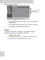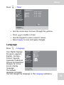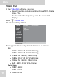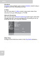
1
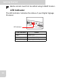
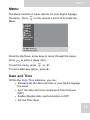
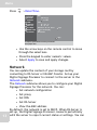
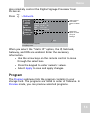
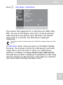
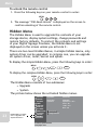
Digital
Signage Processor
SD
AUDIO
12V RES
ET
IN
AUDIO
OUT
VIDEO
IN
DVI
USB
LAN
WIRE
IR
RS 23
2
SignShow D5000
User Manual
Table of Contents
Safety Instructions
iv
Power Cord & adapter Warnings .............................................. iv
Technical Support ...................................................................... v
Declaration of Conformity
vi
FCC Notice ............................................................................... vi
This device complies with part 15 of the FCC Rules. Operation is subject to the following two conditions: ........................................................vi
WEEE Notice ........................................................................... vii
Introduction
1
Overview .................................................................................... 1
Features ...................................................................................... 2
Package Contents ....................................................................... 3
Connectors View ........................................................................ 4
Remote Control .......................................................................... 5
Getting Started
6
Setting up New SD Card Content .............................................. 6
Connecting the Power ................................................................ 6
Inserting the SD Card ................................................................. 6
Removing the SD Card .............................................................. 8
Making Connections .................................................................. 8
Connecting to a Monitor ....................................................................8
Connecting USB devices ...................................................................8
Connecting to a Network ...................................................................9
Connecting Speakers .........................................................................9
Connecting a DVD player or TV STB ............................................10
LED Indicator .......................................................................... 11
Menu
12
Date and Time .......................................................................... 12
Network .................................................................................... 13
Program .................................................................................... 14
Previewing a Program ......................................................................15
Timer ........................................................................................ 15
Language .................................................................................. 16
Video Out ................................................................................. 17
i
Table of Contents
Play Mode ................................................................................ 18
Schedule ...........................................................................................19
S-Video ............................................................................................19
Network Streaming ..........................................................................19
Slide Show .......................................................................................19
Video Repeat ...................................................................................21
Memory Card ........................................................................... 21
IR Control ................................................................................ 22
To lock the remote control ...............................................................22
To unlock the remote control ...........................................................23
Hidden Menu ........................................................................... 23
Upgrade .................................................................................... 24
Upgrading System Driver: ...............................................................24
Content Update Mode from USB memory: .....................................25
System ...................................................................................... 26
How to Use the Digital Signage
Processor
28
Powering On ............................................................................ 28
Powering Off ............................................................................ 28
Playing media files using USB memory .................................. 29
Playing media files on the SD card .......................................... 29
Updating Content ..................................................................... 29
USB Memory Update ......................................................................30
Manual rewrite of SD card by PC ....................................................31
Rewrite through LAN ......................................................................31
Rewrite through WAN .....................................................................32
Specifications
33
Internal Storage ........................................................................ 33
SD card structure .............................................................................33
Configuration File .................................................................... 33
Supported Image Formats ........................................................ 34
Supported Video and Audio Formats ...................................... 34
Video and Audio Specifications ......................................................35
ii
Software Layout Utility ........................................................... 37
Layout Template ...................................................................... 38
Software Limitations ................................................................ 42
Table of Contents
Video Input .............................................................................. 43
Hardware Specifications .......................................................... 45
Tr ou ble sho ot ing
47
Error Messages ......................................................................... 47
FAQ’s ....................................................................................... 48
iii
Safety Instructions & Warranty
Safety Instructions
Use the following safety guidelines to help protect yourself and your
Digital Signage Processor.
•
•
Do not attempt to service the Digital Signage Processor yourself.
Always follow installation instructions closely.
To avoid personal injury from electric shock or fire:
•
•
•
•
Completely power down the Digital Signage Processor when cleaning the
Digital Signage Processor, its components, or chassis, or performing
operations requiring similar steps. To do this, first turn the power off, then
disconnect the AC adapter from the electrical outlet or from any other type
of external power source.
Do not operate the Digital Signage Processor near water, for example, near
a kitchen sink or laundry tub, in a wet basement, by a swimming pool, or in
the rain.
Do not push objects into air vents or openings of your Digital Signage
Processor. Doing so can short out interior components and may cause fire or
electric shock.
Operate the Digital Signage Processor at the recommended
temperature range of +0°C to +40°C (+32°F to +104°F). Store it at a
temperature of -10°C to +60°C (+14°F to +140°F).
Power Cord & adapter Warnings
•
See the Installation Instructions before connecting to the power
supply.
•
Be sure that the power outlet you plug the power cord into is easily
accessible and located as close to the equipment operator as possible.
• When using your power cord, make sure to position it around objects so
it is not cut or punctured.
•
Use only the power cord provided for use with this Digital Signage
Processor in accordance with the table below.
Plug Type
iv
Country
U.S.A. /Canada
EU (except U.K.)
U.K.
Voltage
120*
230
230
* When operating the Digital Signage Processor with its AC 125-240V power supply, use a power
supply cord that matches the power supply voltage of the AC power outlet being used.
Safety Instructions & Warranty
•
Before you connect the Digital Signage Processor to a power source,
ensure that the voltage rating of the AC adapter matches that of the
available power source.
•
•
•
•
115 V/60 Hz in most of North and South America and some Far Eastern
countries such as South Korea and Taiwan.
100 V/50 Hz in eastern Japan and 100 V/60Hz in western Japan.
230 V/50 Hz in most of Europe, the Middle East, and the Far East.
If you use an extension cable with your AC adapter, ensure that the total
ampere rating of the products plugged in to the extension cable does not
exceed the ampere rating of the extension cable.
•
Do not cover the AC adapter with papers or other items that may
reduce cooling; also, do not use the AC adapter while it is inside a
carrying case.
•
To remove power from the Digital Signage Processor, turn it off and
disconnect the AC adapter from the electrical outlet.
•
The plug is the disconnecting device.
Warranty
We warrant that each of our products will be free from material
and workmanship defects for two years from the date of purchase. If
the customer discovers a defect, contact your dealer. Defective
products will be repaired or replaced at no charge to the customer,
provided it is returned during the warranty period of two years.
This warranty does not apply to any products which have been
repaired or altered by persons other than authorized repair
personnel, or which have been subject to misuse, abuse, accident
or improper installation. We assume no liability under the terms of
this warranty as a consequence of such events.
Technical Support
For technical support and service, please contact your dealer or
visit the website indicated at the back of the warranty card.
v
Declaration of Conformity
Declaration of Conformity
FCC Notice
This equipment has been tested and found to comply with the limits for a
Class B digital device, pursuant to part 15 of the FCC Rules. These limits
are designed to provide reasonable protection against harmful
interference in a residential installation. This equipment generates, uses
and can radiate radio frequency energy and, if not installed and used in
accordance with the instructions, may cause harmful interference to radio
communications.
However, there is no guarantee that interference will not occur in a
particular installation. If this equipment does cause harmful interference
to radio or television reception, which can be determined by turning the
equipment off and on, you are encouraged to try to correct the
interference by one or more of the following measures:
•
•
•
•
Reorienting or relocating the receiving antenna.
Increasing the separation between the equipment and receiver.
Connecting the equipment into an outlet on a circuit different from that to
which the receiver is connected.
Consulting the dealer or an experienced radio or television technician for
help.
This device complies with part 15 of the FCC Rules. Operation is subject to the following two conditions:
1. This device may not cause harmful interference, and
2. This device must accept any interference received, including
interference that may cause undesired operation.
CE Marking
This product complies with the principal elements of the safety
objectives of EMC Directive (2004/108/EEC) and the Low Voltage
Directive (2006/95/EC) issued by the Commission of the European
Community. Compliance with these directives implies conformity to
the following European Norms (in parentheses are the equivalent
international standards and regulations):
vi
•
EN55022 (CISPR 22). Electromagnetic Interference
•
EN55024 (IEC61000-4-2,3,4,5,6,8,11). Electromagnetic Immunity
•
EN61000-3-2. (IEC61000-3-2)-Power Line Harmonics
Declaration of Conformity
•
EN61000-3-3. (IEC61000-3-3)-Power Line Flicker
•
EN60950 (IEC60950). Product Safety
Japanese Notice
WEEE Notice
•
•
The Directive 2002/96/EC on Waste Electrical and Electronic
Equipment (WEEE) which entered into force on 13th February 2003, is
to ensure that WEEE are recycled using best available treatment,
recovery and recycling techniques in order to protect human health
and natural resources.
Recycling & disposal:
•
•
•
Do not dispose of your product which has the WEEE logo
(shown as right) on it or on its box in the general
household waste bin.
Be sure to dispose of all your products in the designed
collection facilities for recycling of such hazardous wastes.
Separate collection and proper recovery of your WEEE at
the time of disposal will allow us to help conserve natural
resources. Moreover, proper recycling of WEEE will ensure safety of human
health and environment.
For more information about WEEE disposal, recovery, and collection
points, please contact your local city center, household waste disposal
service, retailer or manufacturer of the equipment.
vii
Introduction
Introduction
Overview
Thank you for purchasing your Digital Signage Processor.
This Digital Signage Processor is a powerful digital engine
for high quality video and graphics. It can perform live
broadcasts, video/audio files, and display tickers. You can
easily control, schedule and deliver multimedia content
through network input. Easily update and change display
contents in real time by connecting to the server.
Its compactness allows for easy integration with PDP’s
(Plasma Display Panel), LCD monitors and televisions.
Multiple zones and layouts make this product capable of
creating vivid and captivating multimedia content to
attract more attention.
Your Digital Signage Processor uses standard media files,
providing a reliable and easy-to-use platform.
Read this chapter to learn more about the features of your
Digital Signage Processor.
1
Introduction
Features
• High Performance. Full HD (1080P) output with
hardware video/audio decoder, supports up to 2 videos
/ 2 graphics/ 2 tickers.
• Compact. The compact and rugged case design makes
it easy to mount and install.
• Network-Manageable. Your Digital Signage Processor
can connect remotely through a Local Area Network.
• Web setting. Use your internet browser to set up your
Digital Signage Processor through the Web interface.
• Content-rich presentation. Supports most standard
media files for a content-rich presentation.
Video: WMV, MPEG1, MPEG2, MPEG4, VC-1
Audio: MP2, MP3, WMA, M4A
Graphics: BMP, JPEG, PING
Ticker: text, RSS
Clock: Support multiple clock formats.
Weather: Showing weather info by RSS feed.
• Multi zone layout.This feature allows you to create
vivid and more attractive presentations.
• Flexible scheduling capability. This feature allows
you to display content on an anytime, anywhere basis.
• S-Video input (for DVD/TV). Your Digital Signage
Processor supports S-video input for DVD and TV.
• Standard storage. Your Digital Signage Processor uses
an SD card for local storage.
• Fanless design.
2
Introduction
Package Contents
When unpacking, please ensure the following items are
included. If any items are missing or damaged, please
contact your retailer.
IN
k Setu
Quic
AUDIO
OUT
VIDEO
IN
DVI
USB
LAN
WIRE
nual
p Ma
SD
12V RESET AUDIO
IR
RS23
2
Digital Signage Processor
Quick Start Manual
Remote Control
CD ROM
Power Adapter
SD Card Protector
Power Cord
AA Battery x 2
DVI-D Cable
(optional)
B
2G
USB Extension Cable (optional)
Wired IR (optional)
3MTM double sided tape
4032 22 mm x 14 mm
3
Audio Cable (optional)
DVI-I to VGA adapter
SD Card 2GB
Introduction
Connectors View
SD
12V
RESET
AUDIO
IN
AUDIO
OUT
VIDEO IN
123 4 5 6
No.
Item
DVI
7
USB
8
LAN
WIRE IR
9 10 11 12
RS232
13
Description
1
Power socket
Use to connect to the power adapter
2
Reset button
Press to reset the Digital Signage
Processor settings
3
Audio In
Use to connect to an external device
such as a DVD player or STB
4
Audio Out
Use to connect to an external device
such as TV line-in or speakers
5
SD card slot
Use to insert the SD card
6
S-Video In
Use to connect to an S-video output
from a DVD player, set-top box, etc.
7
DVI-I port
Use to connect to a DVI-D or DVI-I cable
8
USB port
Use to connect a USB memory drive for
updating content/System driver
9
LAN
Use to connect to a an ethernet
network
10
LED indicator
Indicates the status of the Digital
Signage Processor
11
IR Sensor
Receives incoming remote control
commands
12
Wired IR jack
Use to connect to a wired IR
13
RS232 port
Use to connect to an RS232 cable
4
Introduction
Remote Control
The Digital Signage Processor comes with a remote control
for inputting commands. The diagram and table below
show the keys and basic operation of the remote control.
POWER ON
STANDBY
Keypad
1
1
2
3
4
5
6
7
8
9
4
Power button
5
Standby button
6
Menu button
7
Exit button
0
MENU
2
Arrow keys
SET
SET button
3
EXIT
No,
5
Item
Description
1
Keypad
Press the keys to enter numeric values
2
Arrow keys
Press to navigate through menu
selections
3
SET button
Press to enter or confirm selection
4
Power button
Press to power up the Digital Signage
Processor
5
Standby button
Press to power off the Digital Signage
Processor
6
Menu button
Press to display the on-screen display
(OSD) Menu
7
Exit button
Press to exit the menu or submenu
options
Getting Started
Getting Started
Setting up New SD Card Content
You need to set up the contents of the SD card before using it
for the first time. The sample media files and system drivers
(libxxx.img) for the SD card content can be found in the
included CD-ROM. Use your PC to copy these sample files to
the SD card.
Connecting the Power
1. Connect the power cord to the adapter.
SD
12V RESET AUDIO
IN
AUDIO
OUT
VIDEO
IN
DVI
USB
LAN
WIRE
IR
RS2
32
SD
12V
RESET
AUDIO
IN
AUDIO
OUT V
IDEO IN
DVI
USB
LAN
WIRE IR
RS232
2. Connect the power adapter to the power socket of your
Digital Signage Processor.
3. Plug the power cord to a live outlet.
Inserting the SD Card
Before using your Digital Signage Processor, you must insert
an SD Card. You can use SD cards up to 16 GB in size.
6
Getting Started
1. Insert the SD card in the card slot with the contacts facing
upward.
SD
12V RESE AUDIO
T
IN
AUDIO
OUT
VIDEO
IN
2. Slide it until it clicks into place.
3. To protect the SD card from damage or accidental loss,
screw the SD card protector onto the case. Refer to the
diagram below.
SD
SD
3a.
12V RESE AUDIO
T
IN
3b.
AUDIO
OUT
VIDEO
Note
12V RESE AUDIO
T
IN
VIDEO
IN
IN
in order to avoid an update function failure, do not lock
the SD card.
B
2G
Write protect
lock set to
correct position
7
AUDIO
OUT
Lo
ck
Getting Started
Removing the SD Card
1. Unscrew the SD card protector from the case.
2. Gently push the SD card in until it clicks to release the
lock.
3. Remove the card.
4. Screw the SD card protector back.
Making Connections
Connecting to a Monitor
You can connect your Digital Signage Processor to an output
display device such as a computer monitor or a projector monitor.
You can connect using the DVI-I port.
To connect using the DVI-I port
1. Connect one end
of the DVI-D cable
to the DVI-I port
of the Digital Signage Processor.
2. Connect the other
end to the DVI-I
port of the monitor.
SD
12V RESET AUDIO
IN
AUDIO
OUT
VIDEO
IN
DVI
USB
LAN
WIRE
IR
RS23
2
SD
12V
RESET
AUDIO
IN
AUDIO
OUT
VIDEO IN
DVI
USB
LAN
WIRE IR
RS232
Connecting USB devices
You can connect a USB memory drive using the USB port for
content file updates or system upgrades.
8
Getting Started
Simply plug in the USB
cable of your device
to the USB port of the
Digital Signage
Processor. A USB
extension cable is
provided with your
Digital Signage
Processor package for
easy access and
connection.
SD
12V
RESET AUDIO
IN
AUDIO
OUT
VIDEO
IN
DVI
USB
LAN
WIRE
IR
RS23
2
SD
12V
RESET
AUDIO
IN
AUDIO
OUT
VIDEO IN
DVI
USB
LAN
WIRE IR
RS232
Connecting to a Network
For rapid content file updates, connect to InfoSAP Creator.
To connect to the
network, use the
RJ-45 port.
Connect one end
of the network
cable to the RJ-45
port on your
Digital Signage
Processor and the
other end to your
network hub or
wall socket.
SD
12V
RESET AUDIO
IN
AUDIO
OUT
VIDEO
IN
DVI
USB
LAN
WIRE
IR
RS23
2
SD
12V
RESET
AUDIO
IN
AUDIO
OUT
VIDEO IN
DVI
USB
LAN
WIRE IR
RS232
Connecting Speakers
For a more attention-grabbing display, your Digital Signage
Processor is capable of playing audio files exported from
InfoSAP Creator.
9
Getting Started
Connect speakers using the stereo jack on your device.
SD
12V RESET AUDIO
IN
AUDIO
OUT
VIDEO
IN
DVI
USB
LAN
WIRE
IR
RS23
2
SD
12V
Note
RESET
AUDIO
IN
AUDIO
OUT
VIDEO IN
DVI
USB
LAN
WIRE IR
RS232
Audio files must first be edited by using InfoSAP Creator.
Connecting an Audio In Component
Your Digital Signage Processor supports component Audio-in
from devices such as a DVD player or set-top box (STB).
Connecting a DVD player or TV STB
For vivid media content, you can play back video files directly
from your DVD player or TV STB.
1. Connect the Mini
DIN 4-pin cable
to the Video-in
socket of your
Digital Signage
Processor.
2. Connect the
other end to a
DVD player or TV
STB.
3. Select S-video
Mode in the Play
Mode submenu. See “Play Mode” on page 18 for details.
SD
12V RESET AUDIO
IN
AUDIO
OUT
VIDEO
IN
DVI
USB
LAN
WIRE
IR
RS23
2
SD
12V
RESET
AUDIO
IN
AUDIO
OUT
VIDEO IN
DVI
USB
LAN
WIRE IR
RS232
10
Getting Started
Note
Media content must first be edited using InfoSAP Creator.
LED Indicator
The LED indicator indicates the status of your Digital Signage
Processor.
USB
LAN
WIRE
LED Indicator
LED Indicator
11
IR
RS23
Status
Green
Power is on
Red
On standby mode
Green, blinking
Preparing to standby
2
Menu
Menu
The Menu consists of menu options for your Digital Signage
Processor. Press
Menu.
MENU
on the remote control to activate the
DATE/TIME
NETWORK
PROGRAM
TIMER
LANGUAGE
VIDEO OUT
PLAY MODE
MEMORY CARD
IR CONTROL
Press
to change select.
Press [Set] to enter submenu.
Press the Up/Down arrow keys to move through the menu.
Press
SET
to enter a menu item.
To exit the menu, press
MENU
or
To exit a submenu option, press
EXIT
.
EXIT
.
Date and Time
Within the Date/Time submenu, you can:
• Manually set the date and time of your Digital Signage
Processor
• Sync the date and time via Network Time Protocol
(NTP)
• Enable/Disable daily synchronization to NTP
• Set the Time Zone
12
Menu
Press
MENU
> Date/Time.
DATE/TIME
NETWORK
PROGRAM
TIMER
LANGUAGE
VIDEO OUT
PLAY MODE
MEMORY CARD
IR CONTROL
Date:
Time:
mm/ dd / yyyy
01 / 01 / 2008
hh : mm : ss
00 : 00 : 00
NTP Server: 220 . 130 . 158 . 51
Sync Time Everyday
Time Zone
Sync
Apply
to setup the system date/time and time-synchronization
Press [Exit] to return.
• Use the arrow keys on the remote control to move
through the selections.
• Press the keypad to enter numeric values.
• Select Apply to save and apply changes.
Network
13
You can update the content of your storage card by
connecting to DS-Server or InfoSAP Creator. Set up your
Digital Signage Processor to connect to the server in the
Network submenu.
The Network submenu allows you to configure your Digital
Signage Processor for the network. You can:
• Set network configuration
• Set proxy
• Set DNS
• Set DS-Server
• View the MAC address
By default, the network is set to DHCP. When DS-Server is
set up, the Digital Signage Processor connects periodically
with the server to report current status or settings. You can
Menu
also remotely control the Digital Signage Processor from
DS-Server.
Press
MENU
> Network.
DATE/TIME
NETWORK
PROGRAM
TIMER
LANGUAGE
VIDEO OUT
PLAY MODE
MEMORY CARD
IR CONTROL
Static IP
196.168.1 .225
IP:
Netmask: 255.255.255 .0
Gateway: 196.168.1 .254
211.78 .130 .2
DNS:
00:16:E8:F1:94:7E
MAC:
Proxy
DS-Server
Select type of
connection:
DHCP or Static
IP
Select this
option to enter
proxy IP
settings.
Apply
to setup the network configuration
Press [Exit] to return.
When you select the “Static IP” option, the IP, Netmask,
Gateway, and DNS are enabled. Enter the necessary
information.
• Use the arrow keys on the remote control to move
through the selections.
• Press the keypad to enter numeric values.
• Select Apply to save and apply changes.
Program
The Program submenu lists the program contents in your
storage card. The programs are listed in order of filename. In
Preview mode, you can preview selected programs.
14
Menu
Previewing a Program
DATE/TIME
NETWORK
PROGRAM
TIMER
LANGUAGE
VIDEO OUT
PLAY MODE
MEMORY CARD
IR CONTROL
Program List:
DemoCase.xml
List of the program
contents in your
storage card.
1/1
to preview a program
Press [Exit] to return. Press
to change page when on the list.
• Use the Up/Down arrow keys to move through the
program list.
• To change the page, use the left/right arrow keys.
Press
SET
to select and play the file.
Timer
You can set the timer settings of your Digital Signage
Processor in the Timer submenu. You can:
• Enable daily timers
• Set timers to power on or power off your device
• Set timers to turn the video on or off
15
Menu
Press
MENU
> Timer.
DATE/TIME
NETWORK
PROGRAM
TIMER
LANGUAGE
VIDEO OUT
PLAY MODE
MEMORY CARD
IR CONTROL
Enable Daily Timer
Power-On
Power-Off
Video-On
Video-Off
mm / dd
01 / 01
01 / 01
01 / 01
01 / 01
hh : mm
00 : 00
00 : 00
00 : 00
00 : 00
Apply
to set the timer
Press [Exit] to return.
• Use the arrow keys to move through the options.
• Press
to enable a timer.
• Use the keypad to enter numeric values.
• Select Apply to save and apply changes.
SET
Language
Press
MENU
> Language.
DATE/TIME
Select Language:
Your Digital Signage
English
NETWORK
Deutsch
PROGRAM
Processor supports
TIMER
Français
English, German,
LANGUAGE
Español
VIDEO OUT
French, Spanish,
PLAY MODE
Japanese,Traditional
MEMORY CARD
IR CONTROL
Chinese and Simplified
Chinese for its onscreen display
language.
to set the language
Press [Exit] to return.
The default
language is English.
You can change the language in the Language submenu.
16
Menu
Video Out
In the Video Out submenu, you can:
• Select the video output resolution through DVI, Digital
Video, VGA
• Set to read video frequency from the connected
display
MENU
Press
> Video Out.
Select Video Output Mode
DATE/TIME
NETWORK
PREVIEW
TIMER
LANGUAGE
VIDEO OUT
VIDEO IN
MEMORY CARD
IR CONTROL
SLIDE SHOW
Current Mode:
VGA 1024X768@60
Select Video Output Mode:
DVI
Digital Video
VGA
to set the video output timing
Press [Exit] to return.
The supported video output resolutions are as follows:
DVI
•
•
•
•
•
•
1920 x 1080 / 60 Hz, VESA timing
1680 x 1050 / 60 Hz, VESA timing
1360 x 768 / 60 Hz, VESA timing
1280 x 1024 / 60 Hz, VESA timing
1024 x 768 / 60 Hz, VESA timing
640 x 480 / 60 Hz, VESA timing
Digital Video
17
• 1080P /60 Hz
• 1080i /60 Hz
• 720P /60 Hz
Menu
• 640 x 480 / 60 Hz
VGA
• 1680 x 1050 / 60 Hz, VESA timing
•
•
•
•
1360 x 768 / 60 Hz, VESA timing
1280 x 1024 / 60 Hz, VESA timing
1024 x 768 / 60 Hz, VESA timing
640 x 480 / 60 Hz, VESA timing
The default video output resolution is set at 1024 x 768 @ 60Hz, VGA
timing.
Note
• When changing the output timing, you must make sure
you have the correct cable attached and then press
numeric key “1” on the remote control within 45 seconds.
Otherwise, the settings revert to the original output timing.
• VGA timing requires a DVI to VGA cable connection.
Play Mode
You can select the Play mode in the Play Mode submenu.
Press
MENU
> Play Mode.
DATE/TIME
NETWORK
PROGRAM
TIMER
LANGUAGE
VIDEO OUT
PLAY MODE
MEMORY CARD
IR CONTROL
Select Play Mode:
Schedule
S-Video
Network Streaming
Slide Show
Video Repeat
Apply
to set the play mode
Press [Exit] to return.
Use the arrow keys on the remote control to move through the
selections.
18
Menu
Schedule
Schedule is the default mode. Select Schedule mode to play a
program with the scheduling function.
S-Video
You can also select S-Video mode to play back video files
directly from your DVD player or TV STB.
Network Streaming
You can also select Network Streaming mode to get video files
through the LAN. You can configure the streaming server by
entering the server IP and Port address.
DATE/TIME
NETWORK
PROGRAM
TIMER
LANGUAGE
VIDEO OUT
PLAY MODE
MEMORY CARD
IR CONTROL
Select Play Mode:
Schedule
S-Video
Network Streaming
Slide Show
Video Repeat
IP:
227 .40 .50 .60
Port:
8192
Apply
to set the play mode
Press [Exit] to return.
Slide Show
Configure the slide show mode in the Play Mode submenu.
19
Menu
Press
MENU
> Play Mode > Slide Show.
DATE/TIME
NETWORK
PROGRAM
TIMER
LANGUAGE
VIDEO OUT
PLAY MODE
MEMORY CARD
IR CONTROL
Select Play Mode:
Schedule
S-Video
Network Streaming
Slide Show
Video Repeat
Display Time per Slide:
Folder: /.
3
Seconds
Apply
to set the play mode
Press [Exit] to return.
The content files supported for a slide show are: BMP, JPEG,
PNG. You can set the display time from 3 to 60 seconds per
slide using the arrow keys to move the slider. The default
value is set to 3 seconds. The slide show is displayed
repeatedly.
Note
The system needs to restart before the Slide Show mode settings can take
effect.
In Slide Show mode, when you power on the Digital Signage
Processor, the processor checks the USB memory and reads
image files to start the show. If there is no USB memory
detected, it displays a message Please insert USB memory.
The slide show content is displayed in alphabetical order using
the first character of the file name. The images are resized to
full screen while retaining the aspect ratio.
20
Menu
Video Repeat
You can also select Video Repeat mode to repeatedly play
video files from USB memory.
DATE/TIME
NETWORK
PROGRAM
TIMER
LANGUAGE
VIDEO OUT
PLAY MODE
MEMORY CARD
IR CONTROL
Select Play Mode:
Schedule
S-Video
Network Streaming
Slide Show
Video Repeat
Screen Size
Full Screen
Folder: /.
Normal
Apply
to set the play mode
Press [Exit] to return.
In Video Repeat mode, when you power on the Digital Signage
Processor, the processor checks the USB memory and reads
image files to start the show. If there is no USB memory
detected, it displays a message Please insert USB memory.
Note
Note
Do not unplug the USB memory or SD card during Play Mode. In case this
happens, go to Standby mode and reboot the Digital Signage Processor. See
“Powering On” on page 28.
The system needs to restart before the Slide Show and Video Repeat modes
settings can take effect.
Memory Card
You can see the capacity of your SD card and delete all stored
content in the Memory Card submenu.
21
Menu
Press
MENU
> Memory Card.
DATE/TIME
NETWORK
PREVIEW
TIMER
LANGUAGE
VIDEO OUT
VIDEO IN
MEMORY CARD
IR CONTROL
SLIDE SHOW
Memory Card:
1.9GB
1.8GB
Free
Available
Delete All Content Files
to manage the Memory Card storage space
Press [Exit] to return.
Note
Choosing “Delete All Content Files” deletes all content files in your SD card.
IR Control
IR Control refers to the remote control that is included with
your Digital Signage Processor. In the IR Control submenu, you
can lock the remote control to prevent unauthorized users
from operating your device.
Press
MENU
> IR Control.
DATE/TIME
NETWORK
PROGRAM
TIMER
LANGUAGE
VIDEO OUT
PLAY MODE
MEMORY CARD
IR CONTROL
Select IR Mode:
Normal
IR Lock
Apply
to set the IR mode
Press [Exit] to return.
To lock the remote control
1.
2.
3.
4.
Highlight IR Lock using the arrow keys on the remote control.
Press SET to select.
Select Apply.
A message appears to confirm disabling of remote control.
Select Yes to confirm.
22
Menu
To unlock the remote control
1. Press the following keys on your remote control in order:
MENU
1
2
3
2. The message “OSD Menu Unlock” is displayed on the screen to
confirm unlocking of the remote control.
Hidden Menu
The Hidden Menu is used to upgrade the contents of your
storage device, display system settings, change passwords and
restore factory defaults. To protect the contents and settings
of your Digital Signage Processor, the Hidden Menu is not
displayed on the screen unless you activate it.
There are two level Hidden Menus, in simple hidden memu, only
system driver can be upgraded; in complex one, you can upgrade
all system driver, loder, kernel and splash.
To display the simple Hidden Menu, press the following keys in order:
MENU
SET
To display the complex Hidden Menu, press the following keys in order:
MENU
SET
The Hidden Menu consists of two submenus:
• Upgrade
• System
The picture below shows the activated hidden menus.
23
Hidden Menu consists
of the Upgrade and
System submenu
DATE/TIME
NETWORK
PROGRAM
TIMER
LANGUAGE
VIDEO OUT
PLAY MODE
MEMORY CARD
IR CONTROL
UPGRADE
SYSTEM
Player Name:
DS34c2e8d0
Device Name:
F/W Version:
DS34c2e8d0
System Driver -- V8.17
Kerlen -- V4.1
Loader -- V4.3
MCU -- V4.2
Factory Reset
Change Password
to show the system information
Press [Exit] to return.
Menu
To deactivate the Hidden Menu, turn off your Digital Signage
Processor. The Hidden Menu is not displayed on the screen on
your next power up.
Upgrade
Press
MENU
> Upgrade.
DATE/TIME
NETWORK
PROGRAM
TIMER
LANGUAGE
VIDEO OUT
PLAY MODE
MEMORY CARD
IR CONTROL
UPGRADE
SYSTEM
Select Upgrade File:
System Driver
Loader
Kernel
Splash
Content Update Mode from USB Memory:
Difference Write
Write after Delete
Auto Content Update
to upgrade the firmware
Press [Exit] to return.
Use the Upgrade submenu to upgrade system files in your
Digital Signage Processor. Your Digital Signage Processor
contains four files: System driver, Loader, Kernel, Splash. To
select an item, highlight the option by moving the arrow keys
on the remote control then press
.
SET
Upgrading the System Driver:
1. Select the file to update by moving the arrow keys to
highlight the file then press
.
2. Insert the USB memory to the USB port.The Digital Signage
Processor automatically checks the USB memory for update
files. If no file is found, a “no file” message appears on the
screen. Otherwise, the screen displays a list of available
system driver.
SET
24
Menu
Please refer to the picture below.
DATE/TIME
NETWORK
PROGRAM
TIMER
LANGUAGE
VIDEO OUT
PLAY MODE
MEMORY CARD
IR CONTROL
UPGRADE
SYSTEM
Select library in the USB memory:
lib-ds-player_0623.img
to upgrade the firmware
Press [Exit] to return.
3. Select the system driver then press SET .
4. When the message appears on the screen,
select “Yes” and press SET to start.
It will start upgrading.
Do you want to continue?
Yes
5. The Digital Signage Processor starts
upgrading and displays a message.
6. When the upgrade is complete, a
message appears on screen and the
Digital Signage Processor reboots.
No
Upgrading... Please do not power-off.
Upgrading is finished. System will reboot now.
Content Update Mode from USB memory:
Set up the content update mode in this section. Select
Difference Write or Write after Delete.
When the Digital Signage Processor boots up, it checks the
USB memory first.
If you set Difference Write mode, only files with different
time/date stamps or new files inlcuded on the USB memory
but not on the SD card are updated. Files on the SD card but
not on the USB card are deleted.
If you set Write after Delete mode, all content files in the
media folder are deleted. The content files in the USB
memory are then copied to the SD card.
25
Menu
Auto Content Update:
Select/deselect “Enable Auto Content Update” to enable/
disable daily auto content update. Once you enable auto content
update, you will see the following detail configuration:
• FTP server/Folder: The content directory on FTP.
• User: The user name for login FTP.
• Password: The password for login FTP.
• Time: The dail updated time.
Regarding how to set the auto content update configuration,
please refer to the InfoSAP Creator manual.
System
The System submenu displays system settings and manages
setup options. You can:
• Reset your Digital Signage Processor to its factory
settings
• Change the password for web access.
Press
MENU
> System.
DATE/TIME
NETWORK
PROGRAM
TIMER
LANGUAGE
VIDEO OUT
PLAY MODE
MEMORY CARD
IR CONTROL
UPGRADE
SYSTEM
Player Name:
DS34c2e8d0
Device Name:
DS34c2e8d0
F/W Version:
System Driver -- V8.17
Kernel -- V4.1
Loader -- V4.3
MCU -- V4.2
Factory Reset
Change Password
to show the system information
Press [Exit] to return.
When you select Factory Reset, a confirmation message
appears. Select Yes to continue.
Warning
All settings are erased if you select Factory Reset.
26
Menu
A password is required for web access. To set up a password,
select Change Password.
DATE/TIME
NETWORK
PROGRAM
TIMER
LANGUAGE
VIDEO OUT
PLAY MODE
MEMORY CARD
IR CONTROL
UPGRADE
SYSTEM
Change Password for Web Access: (4-8 Characters)
New Password:
********
Password Confirm:
********
Apply
to change the password for Web access
Press [Exit] to return.
The password must be a 4 to 8 character numeric string.
• Enter a new password.
• Re-enter to confirm the new password.
• Select Apply.
Note
27
Make sure the New Password and Password Confirm are the same to ensure
successful change of password.
How to Use the Digital Signage Processor
How to Use the Digital Signage
Processor
Powering On
Note
Before powering on the Digital Signage Processor, insert an SD card into the
SD card slot.
After performing the necessary connections, you are now
ready to power on your Digital Signage Processor. Press
on the remote control. The LED indicator lights green to
denote power.
POWER ON
Boot Sequence
When you turn on the Digital Signage Processor, it checks the
memory drives connected to your device in a particular order,
this is called the Boot Sequence.
In Slideshow mode, the boot sequence of your Digital Signage
Processor is as follows:
1. Checks the USB drive for USB memory drive connections.
2. Checks the SD card content.
Note
When you accidentally turn on the Digital Signage Processor without any
memory card inserted in the device, a “No Signal” message appears on the
screen. Press
device again.
STANDBY
on the remote control, then press
POWER ON
to reboot the
Powering Off
STANDBY
To turn off the Digital Signage Processor, press
on the
remote control. The LED indicator lights red to denote
standby mode.
28
How to Use the Digital Signage Processor
Playing media files using USB memory
By default, if Slide Show mode is enabled, the Digital Signage
Processor first reads the USB memory drive for media content
when it boots up.
1. Insert the USB memory drive in the USB slot.
2. Turn on the Digital Signage Processor.
The content of your memory drive is displayed on the screen.
Note
Please refer to “ Slide
Slide Show mode.
Show” on page 19 for details on how to enable
Playing media files on the SD card
1. Insert an SD card into the SD card slot.
2. Turn on the Digital Signage Processor. The device boots
up.
3. If there is a schedule program in the SD card, the Digital
Signage Processor plays the program content. Otherwise,
the screen displays the message, “There is no schedule
program at current time”.
Note
Please refer to the InfoSAP Creator manual for more information about playing
content files on the SD card.
Updating Content
Your Digital Signage Processor supports four methods for
content update:
• USB Memory Update
• Manual rewrite of SD card by PC
• Remote rewrite through LAN
• Remote rewrite through WAN
29
How to Use the Digital Signage Processor
The illustration below shows the different content update
methods.
PC with
InfoSAP Creator
PC with
InfoSAP Creator
ork
tw
Ne
SD
SD
12V RESET AUDIO
IN
AUDIO
OUT
VIDEO
12V RESET AUDIO
IN
IN
AUDIO
OUT
VIDEO
DVI
IN
DVI
USB
LAN
USB
WIRE
LAN
IR
WIRE
RS232
IR
RS232
Digital Signage Box
Digital Signage Box
Digital Signage Server
WAN
SD
12V
RESET AUDIO
IN
AUDIO
OUT
VIDEO
IN
DVI
USB
LAN
WIRE
IR
RS232
Digital Signage Box
PC with
InfoSAP Creator
USB Memory Update
A media folder is required for a USB memory update. It must
contain the following three files:
• Schedule files (.she)
• Program files (.xml)
• Media folders (named the same as the .xml file)
30
How to Use the Digital Signage Processor
You can create content by using InfoSAP Creator.
There are two modes for USB update:
1. Mode 1: Delete and copy mode. All content files in the
media folder are deleted. The content files in the USB
memory are then copied to the SD card.
2. Mode 2: Differential copy mode. The file name and date
of the files in the USB memory and the SD card are compared. Only files with different names and/or dates are
copied to the SD card. If there are files in the USB memory and the SD card with the same file name and date,
they are skipped. If the files in the SD card do not exist in
the USB memory, they are deleted.
Manual rewrite of SD card by PC
You can create schedules using InfoSAP Creator and by manually
rewriting the contents of the SD card using a PC. After
creating a schedule via InfoSAP Creator, the following items
appear:
• Schedule file (.she)
• Program file (xml)
• Media folder with the same name as the program file.
Note
Before you start copy, check to make sure your SD card contains a folder
named “media”. If not, create “media” folder. Now, manually copy the
files to your SD card’s “media” folder using your PC’s copy/paste functions.
For more information about creating a schedule, please see
the InfoSAP Creator user manual.
Rewrite through LAN
You can create and upload schedules to Processors via InfoSAP
Creator. See the InfoSAP Creator user manual for more
information.
31
How to Use the Digital Signage Processor
Rewrite through WAN
1. Using DS-Server (optional)
You can create schedules via InfoSAP Creator or DS-Server and
update them to Processors via a DS-Server device. See DS-Server
user manual for more information. DS-Server provides enhanced
Internet funcitonality. Contact your channel provider for more
information.
2. Auto content update
You can set auto content update to Processors via InfoSAP
Creator. See the InfoSAP Creator user manual for more
information.
32
Specifications
Specifications
Internal Storage
The Digital Signage Processor uses an SD card for internal
storage. The SD card must have only one FAT32 partition.
Your Digital Signage Processor supports SD cards with
capacities up to 16GB.
SD card structure
The SD card must have the following files and
folders:
1. System Driver (.img), includes:
• Applications
• Libraries
• Upgrader
2. Media folder, contains:
• Only one Schedule file (.she)
• One or more set of Program File and
Program Folders.
• Each Program File has one (.xml) file and
one folder, respectively
• Program Folders may include the
following:
• still image file, video file, ticker data (.rss) font (.ttf)
3. Config folder. This folder is automatically created.
4. Ds-player folder. This folder is automatically created.
5. Upgrade folder. This folder is automatically created.
Configuration File
33
The configuration file is formatted in XML and named
config.dat. If a config.dat file is present in the inserted USB
memory, the settings are read during boot-up. The device
then reboots for the settings to take effect.
Specifications
Supported Image Formats
The Digital Signage Processor supports BMP, PNG, and JPEG
image file formats.
• BMP (*.bmp): 24-bpp, R8-G8-B8
• PNG (*.png): 24-bit RGB
• JPEG (*.jpg, *.jpeg)
Image resolution should be less than 2047 x 2047.
Supported Video and Audio Formats
Please refer to the table below for video and audio formats
supported by the Digital Signage Processor.
Table 1: Supported Video and Audio Format
Group
WMV
MPEG-1
MPEG-2
MPEG-2
Video(V)
Audio(A)
Codec
V
Windows Media Video 9
V
Windows Media Video 9
Advanced Profile
A
Windows Media Audio 9
V
MPEG-1 Video
A
MPEG-1 Audio layer 2
V
MPEG-2 Video
A
MPEG-1/2 Audio layer 2
A
MPEG-1/2 Audio layer 3
V
MPEG-2 Video (Transport
Stream)
A
MPEG-1/2 Audio layer 2
A
MPEG-1/2 Audio layer 3
Container
File Extension
ASF
.WMV,
.ASF
MPG
.MPG
MPG,
M2P
.MPG,
.M2P
M2V
.M2V
TS
.TS
34
Specifications
Table 1: Supported Video and Audio Format
Group
MPEG-2
MPEG-4
MPEG-4
MPEG-4
VC-1
Video(V)
Audio(A)
Codec
V
MPEG-2 Video (Program
Stream)
A
MPEG-1/2 Audio layer 2
A
MPEG-1/2 Audio layer 3
V
DivX 5.0
A
MPEG-1/2 Audio layer 2
A
MPEG-1/2 Audio layer 3
V
H.264
A
AAC
V
MP4
A
AAC
V
VC-1
Container
File Extension
VOB
.VOB
DivX,
AVI
.DivX,
.AVI
MOV,
AVI,
TS
.MOV,
.AVI,
.TS
MP4
.MP4
TS
.TS
Video and Audio Specifications
1. Windows Media Video 9 (WMV3)
• Supports MP@HL (Main Profile, High Level) up to 1280x720p30 or
1920x1080p25 resolution.
• Does not support CP (Complex Profile)
• Does not support interlaced mode.
• Does not support sprite mode.
• Does not support files encoded using WMV9 BETA.
• Does not support WMV1 OR WMV2.
• Supports elementary video stream bit rate of SDTV (HDTV) up to 20
(35) Mbps.
2. Windows Media Video 9 Advanced Profile (WMVA, VC-1,
WVCI)
35
Specifications
• Supports MP@HL (Main Profile, High Level) up to 1280x720p30 or
1920x1080p25 resolution.
• Supporst AP@L3 (Advanced Profile, L3 Level) up to 1920x1080i25,
1920x1080p25 or 1280x720p60 resolution
• Does not support CP (Complex Profile)
• Does not support interlaced mode.
• Does not support sprite mode.
• Does not support files encoded using WMV9 BETA.
• Does not support WMV1 OR WMV2.
• Supports elementary video stream bit rate of SDTV (HDTV) up to 20
(35) Mbps.
3. MPEG-2 Video (MP2V, MPV2, MP2P, MP2T)
• Supports MP@HL (Main Profile, High Level) up to 1920x1080p25,
1920x1080i30 or 1280x720p60 resolution.
• Supports low delay mode (no B pictures, no frame reordering delay,
handling of VBV underflow).
• Supports an elementary video stream bit rate for SDTV (HDTV) up
to 20 (35) Mbps.
4. DivX 5.0 (DX50), MP4 (MP4V), H.264
• Supports BP@L3 (Baseline Profile, L3 Level) up to 720x480p30 or
720x576p25 resolution, including FMO and ASO.
• Supports [email protected] (Main Profile, L4 Level) up to 1920x1080p25,
1920x1080i30 or 1280x720p60 resolution.
• Supports [email protected] (High Profile, L4 Level) up to 1920x1080p25,
1920x1080i30 or 1280x720p60 resolution.
• Supports up to 180 Mbit/s for CABAC streams.
• Supports up to 135 slices per frame.
• Supports an elementary video stream bit rate for SDTV (HDTV) up
to 20 (35) Mbps.
5. MPEG-1/2 Audio layer 2, MPEG-1/2 Audio layer 3
•
•
•
•
•
Layer 2: supports bit rates up to 384kbps.
Layer 3: supports bit rates up to 320kbps.
Supports up to 2.0 channels
Supports 16-bit and 24-bit samples.
Supports sampling rates of 32, 44.1 and 48 kHz.
6. Windows Media Audio 9 (WMA3, codec id:0x161), Windows
Media Audio 9 Professional (codec id:0x162)
36
Specifications
• Supports up to 2.0 Windows Media Audio 9 channels.
• Supports up to 5.1 Windows Media Audio 9 Professional channels.
7. AAC (MPEG-4 AAC)
•
•
•
•
•
Supports LC (Low Complexity profile).
Supports bit rates up to 384kbps.
Supports up to 5.1 channels.
Supports 16-bit and 24-bit samples.
Supports sampling rates of 32, 44.1 and 48 kHz.
8. Streaming
• Video: MPEG1, MPEG2.
• Audio: MPEG-1 Audio Layer 1/2/3
Software Layout Utility
A software layout utility called InfoSAP Creator (included with
the CD-ROM) is included when you purchase your Digital
Signage Processor. This windows application is used to create
programs and schedules for your Digital Signage Processor.
With this software, you can specify the layouts and content
files to play back. It allows you to do the following:
• Define layouts using default layout templates or blank
layouts
• Assign content to layouts
• Create signage
• Preview layouts
• Create schedules
• Upload schedules through LAN/WAN
• Set auto upload parameters
• Specify video rotation
37
Specifications
For more information, please check the software’s User
Manual inlcuded in the CD-ROM.
Note
You can purchase DS-Server for more powerful Internet functionality.
Layout Template
The Digital Signage Processor supports different types of
layouts. Following are some examples:
• Image only
• Image + Ticker
• Video + Ticker
• Video + Image + Ticker
• Portrait
You can also manually add layers.
Image Only
In an Image only layout, images are shown on screen in Loop
play mode. Audio files can be played at the same time.
Image + Ticker
In an Image + Ticker layout, there is no character quantity
limitation. The ticker, (in Unicode characters), runs from
right to left, or can have sentences scrolling upward or
38
Specifications
downward. Images and the ticker can be overlapped. Audio
files can be played at the same time.
No overlap.
Overlapped. Image and ticker are transparent.
Video + Ticker
A layout can contain a video file and a ticker. The video file
can be from an SD card, S-Video input, or network streaming
(See and follow steps 1-3 of “ Manual rewrite of SD card by PC”
on page 31 to setup streaming video). The video and the ticker
can be overlapped.
No overlap.
Note
Overlapped. Video and ticker are transparent.
If you add an audio file and a video file, the audio source is set to audio
automatically. The video file’s audio track will not be audible.
Video + Image + Ticker
39
A layout can contain a video file, an image and a ticker. The
video file can be from an SD card, S-Video input, or network
stream.
Specifications
Note
If you add an audio file and a video file + image+ticker , the audio source is
set to audio automatically. The video file’s audio track will not be audible.
The video, image and ticker can be overlapped.
No overlap.
Overlapped. Image and ticker are transparent.
Portrait Mode
In Portrait Mode, only Video, Streaming, Image, and Ticker
are supported. The ticker direction is from down to up. There
is no character limitation. The ticker font is Unicode. Audio
files can be played at the same time.
Note
• Vertical ticker just supports Chinese, Japanese, and Korea.
• If user add a audio file, the audio source will be set to audio
automatically.
• Before you start copy, check to make sure your SD card contains a folder
named “media”. If not, create “media” folder. Now, manually copy the
files to your SD card’s “media” folder using your PC’s copy/paste functions.
40
Specifications
Video (2) + Image + Ticker
The Digital Signage Processor supports playback of 2 videos,
an image and a ticker. Possible video combinations inlcude:
• Video file + S-Video input
• Streaming + S-Video input
• Video file + Streaming
Vertical Ticker
The Digital Signage Processor supports playback of 2 videos,
weather images, and 2 tickers. Possible video combinations
inlcude:
• Video file + S-Video input
• Streaming + S-Video input
• Video file + Streaming
Video
Image
Window
Ticker
Video
Ticker
The processor can play weather from RSS, only Yahoo
Weather.rss (http://weather.yahoo.com) is supported.
41
Note
Vertical Ticker only supports Chinese, Japanese and Korean.
42
Specifications
Software Limitations
To ensure the output quality of your Digital Signage Processor,
take note of the following software limitations.
Media file
• The maximum video/audio file size is 4GB.
• Two images + Two tickers + Two video files may be
shown simultaneously.
• If the total of image areas is over 3/4 WXGA:
*One image + Two tickers + Two video files may be
shown simultaneously.
• If WMV or MPEG video bitrate is 6 ~ 16 Mbps:
*Two images + One ticker + One video file may be
shown simultaneously.
• If an H.264 file is inserted:
*One image + One ticker + One video file support.
• The Maximum URL length for an RSS feed in a program
file is 256 bytes.
• The maximum font file name length in a program file
is 128 bytes.
• The Maximum duration of a frame is 24 hours.
Note
The Program file refers to .xml files.
Program file (.XML)
• The maximum source number in an item group is 100.
• The maximum number of item groups in a frame is
100.
• The maximum program name length is 128 bytes.
42
Specifications
Schedule file (.SHE)
• The maximum number of program and control
commands in a scheduling file is 500.
Firmware
• The maximum firmware filename length is 128 bytes.
• The on-screen display only can display 35 files or
folders in a directory on the USB drive. Be sure the
folder containing the firmware files has fewer than 35
files or folders.
Filename:
System driver: lib-xxx.img
Kernel: knl-xxx.bin
Loader: ldr-xxx.bin
Splash: sph-xxx.bin
Processor name
• The maximum processor name length is 64 bytes,
alphanumeric.
Image / Video quality
If an image or video file with 1920 x 1080 resolution is played
back on a display with 1920 x 1080 resolution, scaling is not
done.
Gamma and Luminance Characteristics
Gamma and luminance settings can be adjusted using the
display function. The Digital Signage Processor is adjusted to
display normally on a grayscale test pattern.
Video Input
43
There are two video input modes: Normal mode and Full
Screen mode. Normal mode has an aspect ratio of 1:1.
Specifications
The native resolution video input for NTSC is 720 x 480, while
PAL is 720 x 576.
Normal mode is automatically set for 640 x 480 and 1024 x 768
resolutions.
If the resolution is 1920 x 1080, 1360 x 768, 1680 x 1050 or
1280 x 1024, you have to choose between normal and full
screen mode.
Normal Mode. Aspect ratio of 1:1 (X=Y)
Full Screen Mode.
You can change the desired mode in the Play Mode submenu.
See “ Play Mode” on page 18.
44
Specifications
Hardware Specifications
Processor
CPU: Sigma SMP863X
8 MB Flash memory
256 MB SDRAM
DVI:
1920 x 1080 (1080p) / 60hz, VESA timing
1680 x 1050 / 60hz, VESA timing
1360 x 768 / 60hz, VESA timing
1280 x 1024 / 60hz, VESA timing
640 x 480 / 60hz, VESA timing
Digital Video:
Video Output
Resolution
1080P / 60hz
1080i / 60hz
720P / 60hz
640 x 480 / 60hz
VGA:
1680 x 1050 / 60hz, VESA timing
1360 x 768 / 60hz, VESA timing
1280 x 1024 / 60hz, VESA timing
1024 x 768 / 60hz, VESA timing (default)
640 x 480 / 60hz, VESA timing
Video Input
Audio Output
Audio Input
Network
USB
Storage interface
Storage
IR input for remote control
45
Communication interface
with display
Connector: Mini DIN 7P
S video: NTSC / PAL
Analog stereo line out
Line out L/R x 1, Stereo 3.5
Line in L/R x 1, Stereo 3.5
mini jack
mini jack
RJ45 x 1 (DHCP, HTTP)
No wake on LAN function
USB 2.0 Host x 1
USB mass storage class for USB memory only
SD card I/F x 1 (SDHC)
Max capacity: 16Gbyte
SD card
38khz carrier, NEC format signal
RS232 (TX and RX), 9 pin x 1
Specifications
Wired IR input
Power LED
Reset button
Mini jack: 2.5
(4 pole)
Alternative to IR input
Operation: GREEN
Standby: RED
System settings reset
AC adapter
Input AC 240-100V, 47-63hz
Output DC 12V 2.5A
Power code
Japan, 2 pole, 3.0m
Power Consumption
Weight
Power on: Typ 10W (15W max)
Standby: 1W max
Net weight: 0.9 kg
Gross weight: 2.3 kg
Temperature
Operating: 0-40 ºC
Storage: -10-60 ºC
Humidity
Operating: 10-80%
Storage: 10-90%
46
Troubleshooting
Troubleshooting
Error Messages
This section lists common error messages that may arise during the
use of the Digital Signage Processor, and provides answers and
solutions to these errors.
Error Message
•
•
Check if the SD card is inserted.
The SD card may be damaged. Replace it with a
new one.
System driver not found. Player is
recovering system driver now. Please
DO NOT turn off the player.
•
No System Driver is available on the SD card. The
Digital Signage Processor is attempting to recover
the system driver. Please wait until recovery is
complete.
Player failed to recover system driver.
There is no driver on the SD Card.
•
Recovery of System Driver failed. Re-copy the System
Driver from the CD-ROM to the SD card.
•
Check to make sure that the memory card contains
the necessary media files.
Make sure that all program and schedule files are
saved under the \media file directory.
Player failed to access the SD Card. or
Checking SD Card.
It failed to access the program file (.xml)
SD card is write protected.
47
Solutions
•
•
Please unlock the SD card.
Troubleshooting
FAQ’s
This section lists some frequently asked questions (FAQ) and the
answers to these problems.
Question
Answer
Why can’t I view my video files?
You may be trying to view a video file that is not
supported by the Digital Signage Processor. See
“Supported Video and Audio Formats” on page 34.
Why can’t I play my music files?
You may be trying to play a music file that is not
supported by the Digital Signage Processor.
See“Supported Video and Audio Formats” on page 34.
How do I restore the Digital Signage
Processor to its default factory settings?
1. From the Digital Signage Processor OSD Menu>System, select the “Factory Reset” option.
2. Press and hold the reset button and power on the
Digital Signage Processor until the LED blinks and
stays green.
3. Power off the Digital Signage Processor and press
Power on, 7, 8, 5 on the remote controller in
sequence.
What should I do if the Digital Signage
Processor stops functioning or crashes?
Press
I can’t turn on the device.
The batteries on the remote control may be depleted.
Replace the batteries.
Why the IE shows “Internet Explorer cannot
display the webpage” during upgrading
system driver by web accessing?
1. Please check the network connection.
2. Retry again once the network connection problem
is solved.
Why do I see black screen after the Digital
Signage Processor boot up?
STANDBY
and
POWER ON
on the remote control.
1. After the Digital Signage Processor boot up, press
and hold the reset button to check the current output.
If the LED flash green light means it is VGA output.
If the LED flash orange light means it is DVI output.
2. If you want to switch output between VGA and DVI,
click the reset button after the Digital Signage
Processor boot up. The LED will be flashing during
the output transition.
48