1
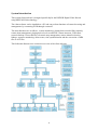
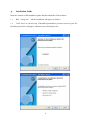
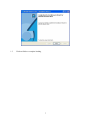
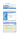
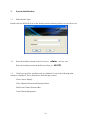
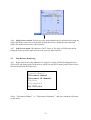
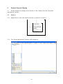
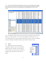
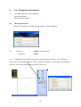
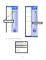
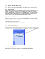
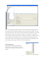
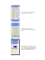
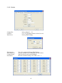
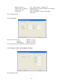
Model - DSD32R
32 channel REALTIME DVR
Client Software Manual
VERSION 3.0
Contents
Page
System Introduction
4
Installation Requirements
5
1.
Installation Guide
6
2.
Uninstall Procedure
8
3.
System Initialisation
10
4.
Remote Monitoring
Methods
Control Panel
Stop Remote Monitoring
12
12
14
15
5.
Remote Playback Startup
Remote Playback Control
Stop Remote Playback
16
18
19
6.
OSD Colour Setup
20
7.
Brief Function Introduction
21
8.
User Management Introduction
Host User Login
DVR Linkage Menu
Remote Host System Parameter Config
22
23
24
27
9.
Screen Split Control Introduction
28
10.
Device List and Control Panel
Host Login/Logout
Time Synchronisation
Start Intercom (audio)
Set Defense (Alarm functions)
Remove Defense
29
30
31
33
34
11.
PTZ Control Panel
Preset Point Setup
36
36
12.
Host Information Realtime Report
37
2
13.
Remote System Parameter Settings
Remote system settings
System
Camera
Audio
Net (Network Settings)
Password
Adjust (Colour and brightness settings)
User Right (Settings rights for Viewer or Operator)
Serial Port (RS232 Connection)
Extend (Set number of working channels)
PTZ (PTZ settings)
Matrix (Set channel sequencing and sequence dwell time)
Remote Record Settings
Time record (Schedule Recording)
Alarm record
Motion Record
Recorded interval
Remote record control
Restore Factory Defaults
External switch control
Split screen control
WEB Upgrade
Remote Log inquiry
System Upgrade
DVR reset
Remote log download
Remote version information
39
39
40
41
42
42
43
43
44
44
45
45
46
47
47
47
48
49
50
50
51
51
52
52
53
53
54
54
14.
Local Setup
DVR (linkage setting)
Preset auto disconnect
Circular monitoring setting (sequencing)
Electronic map setting
Video information display setting
Network Backup
Third Party Software setting
Local system log
Local software version
User Account Management
55
56
59
59
60
64
65
66
67
68
69
15.
Other
Local player
USB data backup
Convert MP4 to AVI tool
70
70
71
73
16.
Internet Explorer Setup
75
3
System Introduction
This system client software is designed specifically for the DSD32R Digital Video Record
using MPEG4/H.264 technology.
The client software can be installed on a PC and can perform functions of remote browsing and
management, by connecting DVR through a network.
The main functions are as follows: remote monitoring, playing back recorded files remotely,
remote host management, playing back a local recorded file, remote intercom, USB client,
network backup of recorded files, electronic map management, remote alarm local action
linkage, sequence monitoring, alarm centre, time synchronisation and the conversion of MP4
files to AVI files.
This following diagram gives a pictorial overview of the client software.
4
Installation Requirements
The recommended PC requirements are as follows
CPU
Intel Pentium4 2.0GHz or higher
Memory
DDR RAM 512Mb
Video card
64MB dedicated video memory supporting Overlay.
Integrated shared video ram is not supported
24 bit colour depth
Network
100Mbps minimum
Resolution
800 x 600, 1024 x 768, 1280x1024
OS
Windows 2000, XP or 2003 are supported
DirectX
9.0 with hardware acceleration
Note
•
The specification listed above is an absolute minimum
•
Graphics processing is very CPU intensive, higher spec CPU will give better results.
•
Satisfactory display of 16 channels will demand a minimum of 64Mb video memory.
5
1.
Installation Guide
Read the contents of the Installation guide and then install the Client software.
1.1
Run “Setup.exe” and the installation will appear as follows:
1.2
Click “Next”to run next step. If Install Program finds a previous version on your PC,
the dialog box below will appear. Otherwise the load will proceed.
6
1.3
Click on finish to complete loading
7
2.
Uninstall Procedure
2.1
Select All Programs and DSD32R Network Client.
2.2
Select Uninstall DSD32R Network Client as above.
2.3
Press Next button.
8
2.4
Click on Finish to complete uninstall.
9
3.
System Initialisation
3.1
Main interface login
Double click the DSD32R Icon on the desktop and the following display screen will be seen.
3.2
Enter the default username in the User box as
admin
Enter the default password in the Password box as
in lower case.
654321
3.3
Click Login and User and Password are validated. If correct the following main
interface is displayed. This is divided into the following sections:
Video Camera Display
Video Channel Selection and Display Position
Full Screen Channel Selection Bar
Control Panel Management
10
Control Panel Management
Video Camera Display
and Display Position
Full Screen Channel Selection Bar
Video Channel Selection
3.4
Screen split
Terminal time means local system time, including Year, Month, Day, Hour,
Minute, Second and Week. Click“Exit” to stop all the current operations and quit.
3.5
Local system needs configuring to allow Client software to run for the first time. Please
refer to section “Local Set”to setup the whole monitoring system. The setup sequence
comprises: host co-activation setup, disconnection time period, sequence monitoring setup,
electronic map setup, OSD information setup, video format and software settings etc .
3.6
The video area is divided into 16 video channels, display monitoring video and remote
playback video information. Change user number in “Host System Setup
Extend
video
user count”in order to limit the number of users that can be connected. The user count is
usually set to 32 including control users and video users.
11
4.
Remote Monitoring
There are several methods to start remote monitoring. Note that if you do not Login you will
not be able to access Remote Settings. Right click DVR and select Login.
4.1
Method 1
4.1.1 Right click the idle video channel and a menu will be displayed.
4.1.2 Select “Connect channel”and the following will be displayed:
4.1.3 Select the operating DVR host in the host information area, and a channel list that refers
to the host DVR will display automatically on the right of the channel selection column. Users
can select the required connecting channels by ticking the relevant box .
4.1.4 Enter the surveillance password in the selection column and at the same time users can
select “save the password or not”, “dual-stream” and“preview”.
(Note: Users can select “Preview” in the “channel connecting” column and therefore can
preview all the channels images.)
12
4.1.5 Dual-stream control
Dual-stream control technology is provided in some DVRs to address limitations in the
network bandwidth and for achieving higher quality video images. This means that the code
stream can be divided into two different (including resolution, frame rate, image quality) parts
when coding. The Main code stream is used for local real-time recording that can be set to a
higher quality setting whereas the secondary code stream can be set at a lower quality setting
for a network connection. This technology therefore provides both a high-quality recording
with lower impacts on network resource.
4.1.6 Press the“connect” button and the progress bar will be displayed. Users can press the
“Cancel” button to cancel the connection if required. The progress bar will automatically
disappear after successful connection. Surveillance signal will be shown in the video channel.
4.2
Method 2
4.2.1 Remote surveillance can also be achieved by selecting from host list in the “Device
list”. Right click the host and choose login. After login, double click the channel of the host
machine or drag the wanted channel to any available video split in the video area, to initiate the
remote monitoring.
4.3
Method 3
4.3.1 Remote monitoring can also be accomplished using the E-map. For details refer to the
instructions on E-map.
Note:
Administrator Password:
333333
Operator Password:
222222
Viewer Password:
111111
Tips:
When selecting “If the password needs to be saved” in the alert dialog column, there is no
need to input the password when clicking the channel connection next time.
13
4.4
Control Panel - Remote Monitoring Control
4.4.1 The “Control Panel”, which is under the menu of Device List in the DVR control
panel, provides functions such as local recording, single frame capture, mute, PTZ control and
camera and aperture control. The functions are detailed below:
4.4.2 Single Frame Capture Single click the “Capture” icon
on the control panel
and the system will create a bmp file. The bmp file will be automatically saved into the “
software install location\Picture” folder. Single Frame Capture will provide detailed analysis
of every frame captured.
4.4.3 Recording:
The local recorded file will be automatically saved into “Software
Install Location\Mpeg” folder. Under remote monitoring, it is recommended using local
recording when an emergency happens.
4.4.4 Mute: This function refers to the sound status mode: ON
close the sound signal on the spot monitor.
OFF
. Open or
4.4.5 PTZ camera and aperture control: This provides two control methods which are fine
adjustment by clicking and main adjustment by continuous pressing. ( Note: Only those who
have the operating authority are entitled to use this function. ).
Refer to the detailed operation instructions as follows:
14
4.4.6 Single Screen switch: Full screen of the single channel can be switched by pressing the
single split image control key or by double clicking the left key. Doing the same operation
again can return to the previous video interface.
4.4.7 Full Screen switch: The shortcut of ALT+Enter or Esc leads to Full Screen switch.
Doing the same operation again returns to the previous video interface.
4.5
Stop Remote Monitoring
4.5.1 Right click on the video channel to be stopped. A menu will then be displayed below.
(This can be also done on the DVR list area, which is in the DVR control panel. Please refer to
the instruction in the DVR list area)
Connect channel
Disconnect channel
Disconnect all channels
Playback
Stop playback
Set OSD color
Select “Disconnect channel” or “Disconnect all channels” and video channels will return
to idle status.
15
5.
Remote Playback Startup
5.1
Remote Playback can display in two interfaces: Video Channel Area and “Download
and playback”interface.
5.2
Mode 1:
5.2.1 Right click on an idle video channel and choose “playback”as follows.
5.2.2 The “Search and playback”interface will be displayed.
16
5.2.3 Choose the DVR name and channel name, then set the corresponding search condition
by entering the From and To dates and the Record Type (Manual Record/Alarm Record/Time
Record) and then click Search. In the right hand box will be displayed a list of the search
results.
5.2.4 Files displayed will be in date order, between the ranges specified in your search. Select
the files you wish to play back. If you need to select multiple record files, press Ctrl+ left
click. After pressing “play”button, the channel will play the chosen file, and the corresponding
status box will display. Meanwhile "Playback" sign is added on the image’s right.
5.3
Mode 2:
5.3.1 Right click on the host and then choose
“Download or Playback”option. The “Download or
Playback”interface will appear. After selecting the
search condition, click “search”button and switch to
“playback”page, and then click “play”button as
follows.
17
5.3.2 Playback interface includes playback progress bar,
play/pause/stop, previous/next, snap, speed up/slow down,
record save, etc
2
5.4
Remote Playback Control
1
5.4.1 When remote playback is running
3
click the “control”item in control panel
4
which is located under “Device List”area
6
and the panel will provide options for
5
8
pause/stop, playback speed control (slow
7
down/speed up), snap(single frame
9
capture), record save and multiple
records previous/next.
.
1.
Play Play the current paused record.
2.
Pause Pause the current playing record.
3.
Stop
4.
Slow down slow down the playback, including X1/2, X1/4.
5.
Speed up
6.
Single frame capture Similar to monitoring single frame capture.
7.
Next
8.
Record Save Same as Monitor Record. While remote playback occurs, users can save
stop the current playing record.
speed up the playback, including X2, X4.
Switch to next record to play, when playing multiple record files.
important video onto local files for later analysis.
9.
Previous Return to the previous record to play, when playing multiple record files.
18
5.5
Stop remote playback
5.5.1 During the playback or after the playback is finished, click the right mouse on the video
channel and the following menu is displayed:
5.5.2 Select “Stop playback”.
19
6.
OSD Colour Setup
6.1
You can set OSD colour on current monitoring channel.
6.2
Right click the monitoring video channel, and an option box will be displayed as
follows.
6.3
Select“Set OSD Color” and an option box will display as follows.
6.4
You can choose a colour in “Basic Colors” or set colour manually in “Define
Custom Colors”. After setting, click “OK” to confirm.
20
7.
Brief Function Introduction
7.1
The DVR system control panel processes the operational controls from the remote and
local system.
7.2
The DVR control panel includes: DVR list/control panel, host information upload,
remote data setup, local setup and other functions. All function modules are listed as follows:
(Refer to next section for detailed introduction)
21
8.
User Management Introduction
8.1
User login interface has two modules:
Main login interface
Host user login interface
8.2
Main login interface
Run the “NetClient.exe”and main login interface will be displayed.
8.3
Enter User :
Password:
8.4
admin (case insensitive)
654321
In addition to the default account you can add separate accounts. You will need to
select “User Account Management”in the “Local Set”module. You may need to scroll down
to find it. Here you can add, modify or delete a new user.
22
8.5
Host User Login Interface
The client software supports three user levels: administrator, operator and viewer. The
administrator has the highest authority and can control the entire client functionality.
A list of the authority rights for these three levels are detailed below.
User
Authority
Remote Surveillance, frame playback, playback, snap, record,
PTZ control, Net backup, USB backup, intercom, E-map, remote
Administrator
system config setting, remote system upgrade, system reset, host
information upload, local setting
Remote Surveillance, frame playback, playback, snap, record,
PTZ control, Net backup, USB backup, E-map, a part of
Operator
function in remote system config setting (external switch
control, split-screen control, remote log inquiry, remote version
information), remote system upgrade, local setting
Remote Surveillance, frame playback, playback, snap, record,
Viewer
USB backup, E-map, a piece of function in remote system
config setting(external switch control, remote log inquiry,
remote version information), local setting.
8.6
You can configure the host information in Local Set DVR\linkage setting.
You must configure the local DVR settings whilst the unit is not logged in. When the local
settings are completed you may view the camera displays without logging in providing you
have the rights, but you can only make amendments to menus after logging in. You can check
whether you are logged in by viewing the box at the top right hand side of the main display
screen.
23
8.7
DVR Linkage Menu
8.8
Enter the local settings. Set the System Information System name and this will alter the
place name associated with the World icon. The unit will be populated with a DVR name and
basic local IP address, of 192.168.0.68 and the client port number of 9998. The Login password
of 333333 default password will also be set. If you left click the mouse after highlighting
DVR No 1, you will see 32 channels displayed as above. If you want to change these settings
then there are options to ADD, EDIT or DELETE. Note that you must not be logged in to make
these changes although you can view camera displays. Press BACK to exit Local Setting menu.
8.9
To make changes to the menus you will need to successfully log on. To do this first left
click on the + next to DVR1. This will display the 32 channels. Now right click on DVR1.
The following diagrams illustrate this.
8.10
Displaying camera channels and starting log on.
24
Left click on + sign
Right click on DVR1
8.11
The following box will be displayed.
Administrator login
Administrator force to login
Administrator logout
Change DVR login Password
Time synchronisation
Connect All
Download or playback
Step forward
Start intercom
Set defense
25
8.12
Left click on Administrator login. Check that the unit has logged on.
Check logged in
8.13 If you now select a camera square for the first camera display window and double left
click the channel number, the camera will be displayed as follows:
Note that you may connect locally without logging in but you will not be able to update
Remote menus.
26
8.14
The default passwords for logging into the DVR are:
Administrator
333333
Operator
222222
Viewer
111111
To change the defaults you need to click on Remote Set tab and select the top icon … .
Remote System Config Setting
The following menu will be displayed: Remote Host System Parameter Config
8.15
Now click on the Password Tab and the following menu will be displayed:
8.16
Change the passwords and confirm each.
27
9.
Screen Split Control Introduction
9.1
Screen split control provides 7 display modes of video:
Single, 4 screens, 6 screens, 9 screens, 16 screens, 25 screens and 36 screens.
9.2
Video channel choice area consists of 36 channel buttons and these buttons are the
channel state lamps currently selected.
9.3
Channel choice button: Press one of them, the relevant video channel is selected and
displays as a single full screen image.
9.4
Status of channel lamp.
Grey
The video channel is available for monitoring and playing.
Orange
Video channel monitoring is connecting.
Red
Video channel is in Remote Playback.
Purple
Video channel is recording locally.
28
10.
Device List and Control Panel
10.1
Device list and control panel include two parts: device list zone and control panel.
10.2
Device List Zone
All hosts added to active linkage setup in the device (DVR) list zone are displayed as a tree
structure. List zone shows the whole structure of the DVR device and users can use the
following functions in the device list zone: Host and channel search, host login/out, modify
local login password, connect all channels, download and playback; start frame play (step
forward), audio talk (start intercom) and alarm on and off (set defense).
10.3
Device Status Indication
In the DVR device list, the logo color in front of the host, indicates the current host status.
Silver grey indicates the host has not logged in.
Yellow indicates the host has logged in.
Green indicates that host is online but is not logged in.
10.4
Host and Channel Search
Input host name or channel number in the search dialogue box. Now press Enter or the search
icon and the target host or channel will be selected automatically after being searched as below:
10.5
Host Management Operation:
Right click on the selected host and device list will display the following menu:
29
10.5.1 Host login/out
The manager should login via the remote host as an administrator through the software client.
The administrator rights include: remote data setup, remote dialog, remote system upgrade,
remote system recover, remote playback, net backup, two way audio talk and host information
upload. These functions are only available after login as an administrator.
There are two ways for administrator to log in: NORMAL login and FORCE login. The login
password may be saved in the software when setting up the host linkage and then the password
is not required when this host logs on.
10.5.2 Normal login:
Select a host name from the list, right click and select “Login (Normal)” interface. If “User
number exceed” is displayed and log in fails, there is another administrator already logged in.
10.5.3 Force login:
Basic steps are similar to normal login, but select “Login (Force)” and this will succeed but
other administrators will be forced to log out. Current host status indicator light in the device
list zone will be yellow after successful login.
Meanwhile above DVR world icon the “Login Host: *” will be displayed. The * stands for
host name.
If “Currently not login” is displayed, then no host has been logged in.
10.5.4 Change DVR Login Password:
Right click on the host name and select Modify Login Password and change the host linkage
password. See 8.14 for details.
30
10.5.5 Time Synchronisation
Time synchronization is the function that can make DVR’
s time be consistent with the
connected PC time.
Only the Administrator has the rights to control the Time Synchronisation feature. Right click
the Host and select Time Synchronization after logging in as Administrator.
“ü”is labeled automatically after Time synchronization has commenced.
Time synchronization fault interval: Update will occur at every 30minute interval after option
started.
Synchronization close
If you select the Time synchronization option again this will close the option and remove the
ticked option.
10.5.6 Connect All
When you need to connect to all channels, right click the host name and select Connect All.
10.5.7 Download or Playback
Right click on host name and select Download or Playback from menu and the following
interface will be shown:
31
Select a target host from the DVR selection zone and a channel list will be displayed below it.
Now select the channel/s required by clicking on the box to the left of the channel. Now enter
the required From and To, date and time, by either entering the specified details or by selecting
from the dropdown boxes. Now click on the Search box. Note that there is an alternative
search criteria for selecting the Record type i.e whether the recording is for a Manual, Alarm or
Time recording and for restricting video type and card number. When downloading, select
Download all, to download all recordings or select first file and press and hold Shift to select
last recording to select a range of files. Press CTRL for individual files.
10.5.8 Step Forward
This option allows images to be played back
frame by frame. If several channels are selected,
then frames will be displayed synchronously across
channels.
32
10.5.9 Start Intercom (audio)
The function provides audio between the PC and DVR through the client software. You will
need a microphone and equipment to listen to the audio through a monitor with an audio
amplifier and speakers, or an audio card on a PC with speakers or a HI-FI amplifier and
speaker system.
There are two operational modes for audio:
Mode one:
Right click the host in “device list”, and choose “start intercom”. Audio will be started. Right
click the host again, the menu will display “stop intercom”. Select it again to quit.
Mode two:
Click on icon
, which is located underneath the “device list”and audio will be started. You
can quit audio by clicking on icon
again.
NOTE:
1. Press “Esc” on the front panel of DVR to quit audio.
2. To activate audio successfully, microphone volume item must be set in recording
control as per example.
33
10.5.10 Set Defense (Alarm functions)
This software provides alarm functions when DVR detects an exception. These can include
disk full status, exterior NO/NC alarm, motion detection alarm, video mask alarm and video
loss alarm. When the software triggers an alarm, this is recorded in the log and the audio
function can also be triggered.
Set defense
Select the alarming target host from the device list, right click and select “Set defense”.
When the host is in alarm status, if exception occurs: disk full alarm, exterior NO/NC
alarm, motion detection alarm, video mask alarm or video loss alarm, host will report
the alarm to NetClient and displays a dialogue box as shown below:
The display lasts for 10 seconds and then disappears but user can click this dialogue
box to see “Alarm Log Check”dialogue box as shown below:
34
This “Alarm Dialogue Check”includes: channel information, disk information, exterior
alarm information and interior alarm information.
Channel Information Display: channel status such as idle, surveillance and recording.
Disk Information Display: disk capability and occupy rate.
Exterior Channel Alarm Display: alarm records when exterior NO/NC alarms.
Interior Alarm Information Display: includes the alarm records of video loss alarm,
video mask alarm and motion detection.
Remove defense
User can reset alarm function if needed to cancel alarming of current NetClient. Select
the required host from device list, right click “Remove defense”as shown below, and alarm
information stops uploading.
35
11.
PTZ Control Panel
11.1
PTZ Control
Firstly set RS485 parameters in “Remote
Host System Parameter Config”in host
system parameters.
Ensure you are logged in and select Remote
Set. Now click on the “Remote System
Config Setting”and then select the “PTZ”
Tab to enter the above menu.
Set the channel number, enable the PTZ option, set the baud rate, Protocol and unique address
as set in the PTZ cameras and click on Yes to Continue. Now click on Apply All. Now click
Apply and then Exit.
If you click the circular PTZ direction keys you can move the PTZ up, down, left and right.
ZOOM+
11.2
IRIS+
FOCUS+
CALL PRESET
Preset Point Setup
When the PTZ is positioned for the first preset point
Enter the first preset point number e.g 1 and then click
the SET PRESET button. A dialogue box is displayed
and press “OK”. To move to a preset point, enter
preset number and click on CALL PRESET button.
ZOOM-
36
IRIS-
FOCUS-
SET PRESET
12.
Host information Realtime Report
After administrator login, the linked DVR will transmit its status information to the terminal.
The information includes: host name, user info online, channel status, host alarm info, external
alarm input and HDD info. Each module switch can be implemented by clicking the column.
You can click the column of the “Control Panel”to make the display Interface telescopic.
Host name column: Display the current host name.
User’s information column: Display all user info which connects the host, including user IP
address, user type, authority and login time.
User type include: video user, control user, download user and intercom user.
User authority includes: viewer, operator & administrator.
Channel status column: Display all the channels’
status after login, including channel name, status,
event and signal.
37
Alarm information: Displays the alarm
info from host to PC after login.
External alarm input: Displays the
external alarm info from host to PC after
login.
HDD information: Display the connected
host’s HDD capacity and available space
percent. The above information will not
display after administrator logout
38
13.
Remote System Parameter Settings
Remote Parameter Configutaion Includes: Remote system settings, Remote record settings,
Remote record control, Restore Factory Defaults, External switch control, Split-screen control,
WEB upgrade, Remote log inquiry, System upgrade, DVR reset and Remote version
information.
Click “Remote Set”Tab and all remote parameter config module icons will be displayed.
13.1
Remote system settings
Click on icon the Remote Host System Parameter Config interface will display. The following
option tabs will be displayed:
39
System / Camera / Audio / Net / Password / Adjust / User Right / Serial Port / Extend / PTZ /
Matrix.
13.1.1 System
System ID
1
Time
Keylock Time
Screen Rotation Time
Recorder Cover Type
Record Quality
Language
Explicit Alarm Window
Video Switch
Auto Record
Pre-Record
Video Format
Beep Alarm
Frame I Interval
Resolution
Stream Type
Screen Show
Frame Rate
Decoder Filter
Allocate a system ID
Year Month Day Hours Minutes
Date & Time
Elapsed time to lock keyboard in seconds
Sequencing time in seconds
Auto or Manual
Select from Low, Basic, Standard, High or Super.
Select from list.
Yes or No.
Not updatable
Yes or No
Yes or No.
PAL or NTSC
Yes or No.
0
800*600 or 1034*768
VBR for networking or CBR for no network
All, State, None or Name.
Full, 1/2F, 1/4F, 1/8F, 1/16F.
1.
40
13.1.2 Camera
Channel No.
Enabled
Mask Area
Mask Active
Record Reserve
Channel Name
Resolution
Select channel 1 ~ 32
Yes / No (depends whether selected or not)
Privacy Mask Setting
Yes / No (Activates Privacy Mask Setup)
Prioritise number of recording days for this camera
Specify name for this camera channel
Record resolution setting (CIF / HD1 / D1/ ---)
41
When setting resolution DVR will record at CIF on all channels. If selecting HD1, which is
2CIF, then you can only set half the streams at HD1. If selecting D1, which is 4CIF, then you
can only set one quarter of streams at D1.
To save changes for all channels click on Apply All or just click Apply. The click on Exit.
13.1.3 Audio
You can set up to 16 channels for audio. Select from Include / None.
13.1.4 Net (Network Settings)
Example:
Set the IP address
Subnet Mask
Gateway
Server Port
192.168.000.068
255.255.255.000
192.168.000.001
9998
42
Monitor Protocol
Alarm Center IP Address
Alarm Center Port
Link Speed
TCP / UDP / Mcast Default TCP
000.000.000.000 (Enter IP address) Tick Enable
4000 Default port
Auto / 10m Half / 10m Full / 100m Half /
100m Full.
Press Apply then Exit.
13.1.5 Password
Set password for Viewer
(default = 111111)
Operator
(default = 222222)
Administrator
(default = 333333)
Enter password in left column and repeat in confirm box.
13.1.6 Adjust (Colour and brightness settings)
Press apply then Exit.
43
13.1.7 User Right (Setting rights for Viewer or Operator)
The Administrator has full rights but the Viewer and Operator can have restricted rights.
Select Enable or Reject for monitoring and playback modes. Click on Apply All to select all
channels and then press Apply. The press Exit.
13.1.8
Serial Port (RS232 Connection)
Set the baud rate and parity attributed for the RS232 settings.
44
13.1.9 Extend (Set number of working channels)
Video User Count
Alarm Output
Video Mask
Sensitivity
Disk Error
This allows you to set the number of channels in use.
This can be set 0 ~ 32.
Associates an alarm output. Select 0 ~ 4.
Enable or Disable this setting.
Set sensitivity level 0 ~ 99
Set to Hide or Show.
13.1.10 PTZ (PTZ settings)
Channel Number
Enable
Baud Rate
(Those in bold popular settings)
Select channel 1 ~ 32
Yes / No to enable PTZ
Select Baud Rate 2400 / 1200 / 4800 / 9600 / 19200
45
Parity Bit
No / Odd / Even
Protocol
PELCO-D / DL-0001 / FASTRAX / PANASONIC /
ELEC / SAMSUNG / KATATEL / HD-600 / T3609HD /
LILIN / PELCO9760 / KRE301 / PIH-1016 / PD-CONST /
PD-NW / JC4116 / SONY / YAAN / ENKEL
1 ~ 255
1/2/3
No / Yes
No / Yes
Yes / No
Address
Speed
Reverse Vertical
Reverse Horizontal
Continue
Click on Apply All for all streams and/or press Apply for one stream. Then Exit.
13.1.11 Matrix
Set channel sequencing and sequence dwell time. Select channel number 1 ~ 32 and sequence
dwell time 005 seconds ~ 999 seconds. Click on Apply and then Exit.
46
13.2
Remote Record Settings
Click on Remote record config setting to setup recording options. The following screen with
the following record tabs will be displayed. These include Time record, Alarm record, Motion
record and Recorded interval.
13.2.1 Time record (Schedule Recording)
The above display shows the Time record schedule.
Channel
Enter channel number 1 ~ 32
Quality
Select either Low / Basic / Standard / High / Super
Frame Rate
Full / 1/2F / 1/4F / 1/8F / 1/16F
CBR
CBR - Constant Bit Rate / VBR –Variable Bit Rate
(CBR for non networking VBR for networking)
You have the option to select Every Day with two time periods or select for each day of the
week from two time periods. Click on Apply All to set for all channels and then Apply. Then
press Exit. Note that time periods from each of the two time periods must not overlap and time
periods must run chronologically. Ensure that after selecting a period that the Active box is
ticked.
13.2.2 Alarm record
47
Alarm In
Alarm Input
Alarm Out
Alarm Time
Record Time
PTZ Preset
Record Channel
You can set up to 16 alarms. Enter alarm 1 ~ 16.
Select Open or Close alarm (Normally Open/Normally Closed)
None / Port 1 / Port 2 / Port 3 / Port 4.
Set elapsed time 1 ~ 999 seconds
Set recording time 30 ~ 999 seconds
Select PTZ preset number 01 ~ 99
Click on Settings for the following display:
Record Quality
Frame Rate
Bit Rate
Select from Low / Basic / Standard / High / Super.
Select from FULL / 1/2F / 1/4F / 1/8F / 1/16F
CBR constant bit rate when no network
VBR variable bit rate when networking
First Alarm selection period
Second Alarm selection period.
Time 1
Time 2
13.2.3 Motion Record
48
Channel No.
Output
Alarm Time
Record Time
PTZ preset
Sensitivity
Select from channel 1 ~ 32
None / Port1 / Port2 / Port3 / Port4
01 ~ 999 seconds
30 ~ 999 seconds
01 ~ 99
01 ~ 99
Area Setup
Click on Set to display:
Frame Rate
CBR / VBR
FULL / 1/2F / 1/4F / 1/8F / 1/16F
Constant Bit Rate for non networked system
Variable Bit Rate for networked systems
Low / Basic / Standard / High / Super
First time period with 24 hour day
Second time period with 24 hour day
Save for this channel
Set for all channels
Record Quality
Time 1 From / To
Time 2 From / To
Apply
Apply All
13.2.4 Recorded interval
49
Recorded Interval
13.3
Set between 2 ~ 240 minutes
Remote record control
Click the icon above and remote record control interface will be displayed. Select a channel
and press the “start”button and the channel will start to record. Cancel the channel and press
“start”button to stop channel recording.
13.4
Restore Factory Defaults
Click the icon and the following will be displayed. Click “OK”button to restore factory
defaults.
50
13.5
External switch control
Click the icon to enter external switch control. This function allows control of the DVR’s
external alarm output. Every switch corresponds with a different alarm output, so you can
control alarm output randomly.
13.6
Split screen control
Click the icon to display the split-screen control interface. This allows control of the DVR’s
split-screen facility, remotely.
51
13.7
Web Upgrade
SPECIAL NOTE: On no account should this option be used unless your supplier has
provided a file and instructions. Loading incorrect files can functionally disable the DVR
and can cause irreversible damage. Your warranty will not cover these issues.
13.8
Remote Log inquiry
Click the icon to enter the remote system log inquiry interface. Here can be found the system
operation and alarm status, including “system operation log”and “system alarm log”.
System operation log: When system is running, all operations are logged in the “system
operation log”. About 300 entries are stored at most.
System alarm log: When system is running, if any abnormal event occurs or if an alarm
occurs, the information will be stored in the “system alarm log”. About 300 entries are stored at
most.
52
System Operation Log
System Alarm Log
13.9
System Upgrade
SPECIAL NOTE: On no account should this option be used unless your supplier has
provided a file and instructions. Loading incorrect files can functionally disable the DVR
and can cause irreversible damage. Your warranty will not cover these issues.
13.10 DVR reset
53
This option will reboot the DVR.
13.11 Remote log download
This allows user to download the remote log.
13.12 Remote version information
.
This provides the remote system version number.
54
14.
Local Setup
When client software is successfully installed, local system initialisation is required, including:
host\linkage setup, disconnect time setup, circular monitor setup, electronic map setup, video
information add setup, net backup, third software setup, local system dialogue and system
software.
Select “Local Setup” from the vertical menu items to show all icons of local setup.
Click here for
User Account
Management
55
14.1
DVR \ linkage setting
Host, linkage setup dialogue consists of system connect directory tree on left and system
information, host information, channel information on right.
14.1.2 System Connect Directory Tree:
It shows the connection information between current host and other hosts in the surveillance
system, and also the channel information of the hosts. Select a node from the directory tree.
Information about the node is displayed on the right of this display.
stands for surveillance system root;
stands for the end client host;
stands for host channel.
56
14.1.3 System Information:
This displays the surveillance system name and provides the function of modifying the name.
14.1.4 DVR Information:
Information of selected DVR host is displayed, such as host IP, host name, connection port and
host channel number. User can add, modify and delete host.
DVR name:
Enter DVR Hostname
DVR IP Address:
Enter local DVR IP Address. Default address 192.168.0.68
Connect Port:
Enter Port number : Default 9998
Login Password:
Enter DVR password: Default 333333
DVR channel:
Enter 32 channel
Add host:
Add a new client to connect this host to the system.
Edit:
Change existing information for this Host.
Delete:
Delete the Host.
57
Use port 9998 for the Client Software port. If you enter zeros for the IP address and click on
Obtain DVR setting automatically, the DVR will use DHCP to automatically provide an
appropriate IP address. Note that this can only be used if connected to a modem/router.
14.1.5 Channel Information:
This displays the selected channel name, triggers ways of starting linkage surveillance and also
provides modification of the above information. When selecting a channel, select from the
corresponding node and the channel name will be displayed as below. You can amend channel
name by clicking on Edit. You cannot use the same name twice within a Hostname.
Surveillance Trigger: This provides surveillance during startup, video masking and motion
detection. When the system is in alarm status, if the selected trigger condition is triggered,
surveillance and recording start automatically.
Note: The precondition of linkage surveillance and local recording is dependent on the
NetClient running and in alarm status and has nothing to do whether admin is logged in or not.
14.1.6 Alarm Information
When admin is logged in and an external alarm occurs, surveillance and recording is triggered
automatically by the NetClient. Set the channel alarm name, linkage recording time, linkage
recording channel and linkage surveillance channel. This allows a different channel to be
monitored and a different channel to be recorded.
58
Alarm Name:
The initial value is the channel number but this can be modified.
Please note that the same name is not allowed to be repeated for
the same host.
Channel Linkage Setup:
Surveillance Channel:
The channel name of the referent host that needs linkage alarm is
displayed in the corresponding dialogue, click
icon, the drop
down list shows the channel set (multi optional) of the alarm
linkage auto surveillance, namely alarm from one channel can
trigger multi channel surveillance.
Surveillance Duration:
This is the time length of auto start surveillance. Lowest value is
30 seconds, value range is 30-999 seconds. Linkage surveillance
can be stopped manually.
Note: Then recording time must be longer than the monitoring time.
14.2
Preset auto disconnect
The remote host can be automatically disconnected by setting this option. This includes the
surveillance connection, playback connection, user login connection and audio talk connection.
Auto disconnect time can be set to 30 minutes, 1 hour, 2 hours or Keep option that does not
automatically disconnect.
14.3
Circular monitor setting
The Circular monitor setup allows channel sequencing. You can select a list of channels from
different hosts and set the total monitoring time, the time each image is displayed and the
image display. Select the channels by selecting from the left hand column and clicking on right
arrow key >. If you wish to select all channels on a DVR select the >> box.
59
The left side of circular monitor setup displays the channels that are not in the sequencing list
and those on the right, are. If you want to delete a channel or DVR from the right hand
sequencing list, select the channel or DVR and press the < for channel or << for DVR.
Total time:
Sequencing Time: the whole time that circular monitor lasts in minutes.
Image interval: The dwell time of each channel.
Image quantity: When in sequencing mode you can select the number of channels displayed at
the same time. Select 1,4,8,16 to have a single screen, 4 screen, 8 screen and 16 screen display.
Start sequencing: Click to commence sequencing mode. You may be requested to confirm the
password if not set as host linkage password.
14.4
Electronic map setting
Key Words
Tree List: This shows the nodes and their hierarchical level .
Node: An element in the tree list. This branch can be any one of an area, host or camera.
Area: Represents a geographical position, shown as
Host: Digital Video Recorder shown as
Camera: The connection device used for input videos for every channel of DVR, shown as
.
Surveillance in real time with the electronic map is based on DVR, so before using surveillance
with the electronic map, user has to set the DVR in “Host Linkage Setup”in “Local Settings”.
60
The following is a sample of an electronic map of Scotland.
a. Main Map
Edit Electronic Map
Right click in the tree list to display the following map edit dialogue box. The electronic map
edit consists of the following 5 functions.
b. Map Edit Menu
Add Map
The map can be tied to an area or a host. When double clicking, this displays the map for this
node. The map also includes the lower hierarchical levels.
61
c. Add Map File
Save Map
Save nodes of tree list to the settings file (Note: all the node information from the whole list
can be saved at one time, so user can select save after finishing the whole update).
Add Node
d. Node Property
To add a node in the current tree list, the node is added below the current selected node. Select
a node type according to different node types; user may have to input host and channel
information. The hosts in the host list are already set in the host linkage setup. Select a DVR
62
and channel list displays the video channels according to the current host. Select a channel and
click “Add”to add this channel or click “Cancel”to cancel this operation.
Note: If the type is area, host and channel information are not required but when the type is
host, host information is required.
Edit Node
Edit node properties are similar to add node.
Delete Node
Delete a node from the tree list on the right of electronic map. This operation also deletes the
corresponding location icon on the map.
Zoom In/out
In electronic map edit mode, the scales of different map files may be different. The icons may
not fit the maps, so user can resize the node icons. Select a node, click
and
to enlarge the icon
to reduce the icon. Below shows the icons which are three times bigger than original.
e. Main Image For Tree Structure
Video Surveillance Operation
At the start point of electronic map operation, the main image above is shown.
If the node stands for an area of a host, right clicking on the node shows menu f. If the node is a
camera, right click on the node.
63
f. Host Menu
g. Camera Menu
Click “Connect”and the processing bar will be displayed. If connection is successful, channel
surveillance screen will be displayed as per diagram h. Double click surveillance screen to
enlarge screen to full a screen.
h. Channel Surveillance Screen
14.5
Video information display setting
When in monitoring mode or remote playback, in the video region above the channel image,
current remote host name and channel information are added. This information is selected from
the Video Information setting dialogue box. Information is added by default.
64
14.6 Network Backup
This provides the function to download recorded video from the remote host to local backup.
Click Net Backup button in Local Setup to display dialogue box below. Input video start time,
end time and channel number for search criteria and click “Search”to recorded files.
Click “Select Path”to display download file save path. Select required backup file from the
list. You can use the Ctrl + left mouse button to select multi records. Now click the “Download
File”to start download.
65
Files are download in two different ways. You can do a file search download or a schedule
search download. File search download is based on the displayed name while schedule search
download is based on the time.
When download completes, system displays Download Finished, click “OK”.
Note: If you select “Convert to AVI Format”before initiating download, the downloaded
files are converted to AVI format automatically when download is finished.
14.7 Third Party Software setting
Through the third party software setup function, local software from another path can be
launched directly without logging off the background. When selecting the third party software,
the following menu is shown.
66
Click “Add”and select the third party software, open and input the name and click “Save”.
This third party software is shown in the “Other Function”module. Users may click the icons
in the “Other Function”to launch the program.
14.8
Local system log
Through local log, user knows the modification to remote host parameters and the alarm
information transferred from the remote host.
Alarm Log: When the system is running, if a channel in the login host alarm occurs, it is
recorded in the alarm log for investigation.
67
System alarm dialogue search display
Note: Local log may save up to 1000 records. When the records reach 1001, the earliest 200
records are deleted automatically.
14.9
Local software version
NetClient version example:
68
14.10
User Account Management
This option allows you to change the default or existing password associated to a username.
The default username is admin and the logon password for the client software is 654321
69
15.
Other
If you click on the Other tab the
following menus are displayed.
15.1
Local player
The function is used to playback all the recorded files saved on the PC’s HD. These files
include: monitoring recording, remote playback, alarm connection, network download, USB
backup, and local records.
Local play startup
Start “Local play”from Start menu of the system, look like the following displays or Press
local Playback button.
Local Playback operation interface appears after the startup.
70
Local Playback Operation Interface
15.2
USB data backup
USB Backup provides the function to read files from USB device and play and backup to local
disk. When backing up with the USB device, make sure current host is connected with
available USB device.
Start USB
Option 1:
From system start menu as shown below:
When USB backup operation interface shows up, select “Open Backup Disk”in “File”item, or
just press the button
, system will guide you to find the USB disk information. Select a
USB disk and then press OK and the Backup menu is displayed..
71
Option 2:
Press USB Data Backup button
from “Other”menu tab to start USB backup program
and select “Open Backup Disk”in “File”from the USB backup operation interface.
Alternatively press the button
, and system will guide you through finding the USB disk
information and selecting a USB disk, then press OK and following menu will be displayed:
Main interface consists of Menu Control, Backup List, Backup Records and Backup
Information.
Menu Control: Offer functions such as open USB device, close and quit NetClient.
Backup List: Displays all backup records on USB device. Once remote host has a file backed
up to a USB device, a backup record will be automatically created and saved to USB device.
Backup Records: Every backup record contains information about the record file, including
the channel number, record start time, record end time, record type, record quality and whether
audio is recorded.
Backup Information: Record backup information includes backup run time, remote host
backup search start time, backup search end time, total number of backup files and the total
size of the backup files.
72
USB Backup Operation
After successfully reading, USB backup records will be displayed in backup list. Select a
backup record which contains the backup file. All the files information this record contains,
will be displayed in the backup record files information. Select a file record that requires
downloading. You may use Ctrl+left mouse button to select multi records. Now right click
mouse and choose “Download”from the
box and a display will show progress.
USB Backup File Display
To play the backup file, user does not need to download the files from the USB device to local
PC folder as the files can be accessed directly from the USB device. Play control includes the
following features: START/PAUSE/STOP, Play Speed Change, Frame Capture, Local record,
Silence and Full Screen Switch.
To play the files, make sure to connect the USB device then open the device.
(Note: USB device only provides the function for single file play and not multi-file play.
15.3
Convert MP4 to AVI tool
This function plays MP4 files in a normal media player in WINDOWS OS.
Start MP4ToAVI format convert:
Option 1: Start by “Start
Programs Install Software Name
73
MP4ToAVI”.
Option 2:
in “Other”menu tab in NetClient to start MP4ToAVI format convert.
Press
When you have started the program you will have the following interface. Select an .MP4 file
and save path for .AVI file.
Click on “Convert”after selecting the save path and the following image shows the interface
after successful conversion.
Now the .AVI file can be played by a normal media player.
74
16.
Internet Explorer Setup
Do the following configurations for the first time using IE web view:
16.1
Make sure that PC has installed Microsoft IE6.0 or later version and Direct9.0 or later.
16.2
Through the menus of “TOOLS” “Internet Options” “Security” “Internet Security
Level Customize Level”as shown in figure“ActiveX Controls and Plug-ins”option “ActiveX
Controls Hint”“Download unsigned ActiveX controls”“Download signed ActiveX
controls”“Initialise and script ActiveX controls not marked as safe”“Run ActiveX controls and
plug-ins”select “Enable” as shown below:
Keep other options as default.
16.3
In order to keep IE safe, return “Inter Security Level”to default or customised settings.
Special Note
When using WEB access add “ 998”after host IP address.
For example, input http://10.0.0.188:998 in IE address for the IP address of “10.0.0.188”
75