1
Owner's
Manual
®
5.5 HP
17 raNCHTUNE WmDTH
REAR TINE WITH
COUNTER ROTATBNG TINE_
TILLE
Model No.
917.293302
Safety
o Assembly
o Operation
o Maintenance
o EspaSol
o Repair Parts
CAUTION:
Read and follow all
Safety Rules and Instructions
before operating this equipment
Sears,
Roebuck
and Co., Hoffman Estates, tL 60179
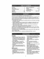
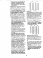
Warranty ................................................... 2
Safety Rules ............................................. 2
Product Specifications
.......................... 4
Assembly ................................................
5
Operation .........................................
3 & 8
Maintenance .........................................
t3
LIMITED TWO YEAR WARRANTY
Service and Adjustments ...................... 15
Storage ..........................................
3 & 19
Troubleshooting .................................... 20
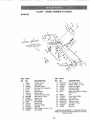
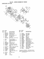
Illustrated Parts List .............................. 42
Parts Ordering ........................ Back Cover
ON CRAFTSMAN
TILLER
For two (2) years from date of purchase, when this Craftsman Tiller is maintained, lubricated, and tuned up according to the operating and maintenance instructions in the
owner's manual, Sears will repair free of charge any defect in material or workmanship.
This Warranty does not cover:
° Expendable items which become worn during normal use, such as tines, spark plugs,
air cleaners and belts.
Repairs necessary because of operator abuse or negligence, including bent crankshafts and the failure to maintain the equipment according to the instructions contained in the owner's manual.
• If this Craftsman Tiller is used for commercial or rental purposes, this Warranty
applies for only thirty (30) days from the date of purchase.
Warranty service is available by returning the Craftsman power mower to the nearest
Sears service center/department
in the United States. This warranty applies oniy while
this product is in use in the United States°
This Warranty gives you specific legal rights, and you may also have other rights which
vary from state to state.
SEARS, ROEBUCK AND CO., D/817WA, HOFFMAN ESTATES, IL 60179
TRAINIING
Read the Owner's Manual carefully. Be
thoroughly familiar with the controls and
the proper use of the equipmenL Know
how to stop the unit and disengage the
controls quickly°
° Never allow children to operate the
equipment. Never allow adults to operate the equipment without proper
instruction.
• Keep the area of operation clear of all
persons, particularly small children, and
pets.
PREPARATION
o Thoroughly inspect the area where the
equipment is to be used and remove all
foreign objects.
o Disengage all clutches and shift into
neutral before starting the engine (mo -
tor)_
• Do not operate the equipment without
wearing adequate outer garments. Wear
footwear that will improve footing on
slippery surfaces.
° Handle fuel with care; it is highly flarnrnable.
° Use an approved fuel container.
° Never add fuel to a running engine or
hot engine.
o Fill fuel tank outdoors with extreme care.
Never fill fuel tank indoors.
° Replace gasoline cap securely and
clean up spilled fuel before restarting_
o Use extension cords and receptacles as
specified by the manufacturer for all
units with electric drive motors or electric
starting motors.
o Never attempt to make any adjustments
while the engine (motor) is running
(except where specifically recommended by manufacturer).
OPERATION
MAINTENANCE
AND
STORAGE
° Keep machine, attachments, and
• Do not put hands or feet near or under
accessories in safe working condition.
rotating parts.
• Check shear pins, engine mounting
o Exercise extreme caution when operatbolts, and other bolts at frequent intering on or crossing gravel drives, walks,
vals for proper tightness to be sure the
or roads. Stay alert for hidden hazards
equipment is in safe working condition.
or traffic. Do not carry passengers.
. Never store the machine with fuel in the
o After striking a foreign object, stop the
fuel tank inside a building where ignition
engine (motor), remove the wire from
sources are present, such as hot water
the spark plug, thoroughly inspect the
and space heaters, clothes dryers, and
tiller for any damage, and repair the
the like. Allow the engine to cool before
damage before restarting and operating
the tiller.
storing in any enclosure.
•
Always refer to the operator's guide
o Exercise caution to avoid slipping or
instructions for important details if the
falling°
° tf the unit should start to vibrate abnortiller is to be stored for an extended period.
mally, stop the engine (motor) and check
,_kCAUTION:
Always disconnect spark
immediately for the cause. Vibration is
plug wire and place wire where it cannot
generally a warning of trouble.
contact spark plug in order to prevent accio Stop the engine (motor) when leaving
dental starting when setting up, transportthe operating position.
ing, adjusting or making repairs.
o Take all possible precautions when leaving the machine unattended. Disengage
,_WARNING
the tines, shift into neutral, and stop the
The engine exhuast from this product conengine.
tains chemicals known to the State of
o Before cleaning, repairing, or inspecting,
California to cause cancer, birth defectd, or
shut off the engine and make certain all
other reproductive harm°
moving parts have stopped, Disconnect
the spark plug wire, and keep the wire
away from the plug to prevent accidental
starting. Disconnect the cord on electric
motors°
o Do not run the engine indoors; exhaust
fumes are dangerous.
o Never operate the tiller without proper
guards, plates, or other safety protective
devices in place.
° Keep children and pets away.
o Do not overload the machine capacity
by attempting to till too deep at too fast a
rate.
o Never operate the machine at high
speeds on slippery surfaces. Look
behind and use care when backing.
o Never allow bystanders near the unit.
. Use only attachments and accessories
approved by the manufacturer of the
tiller..
o Never operate the tiller without good visibility or light.
o Be careful when tilling in hard ground.
The tines may catch in the ground and
propel the tiller forward. If this occurs,
let go of the handlebars and do not
restrain the machine°
3
PRODUCT
MAINTENANCE
SPECIFICATIONS
HORSEPOWER:
5.5 HP
DISPLACEMEN]_
13 CU. IN.
GASOLINE CAPACITY:
4 Quarts
Unleaded
OIL (API-SFiSG/SH):
(CAPACITY:
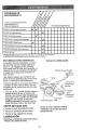
A Sears Maintenance Agreement is available on this product. Contact your nearest
Sears store for details.
CUSTOMER
Regular
SPARK PLUG :
(GAP: .030")
RESPONSIBILITIES
o Read and observe the safety rules.
° Follow a regular schedule in maintaining, caring for and using your tiller:
o Follow the instructions under' the
"Maintenance" and "Storage" sections of
this Owner's Manual.
SAE 30
(Above 32°F)
SAE 5W-30
(Below 32°F)
20 oz.)
AGREEMENT
Champion RJ19LM
OR J 19LM
_kWARNING:
This unit is equipped with
an internal combustion engine and should
not be used on or near any unimproved
forest-covered, brush-covered or grass
covered land unless the engine's exhaust
system is equipped with a spark attester
meeting applicable local or state laws (if
any). If a spark arrester is used, it should
be maintained in effective working order by
the operator.
In the state of California the above is
required by law (Section 4442 of the
California Public Resources Code). Other
states may have similar laws. Federal
laws apply on federal lands° See your
Sears Authorized Service Center for spark
arrester. Refer to the Repair Parts section
of this manual for part number,
Congratulations
on your purchase of a
Craftsman Tiller: It has been designed, engineered and manufactured to give you the
best possible dependability and performance.
Should you experience any problems you
cannot easily remedy, please contact your
nearest authorized Sears Service
Center/Department.
We have competent,
well-trained technicians and the proper
tools to service or repair this unit.
Please read and retain this manual. The
instructions will enable you to assemble
and maintain your tiller properly. Always
observe the "SAFETY RULES",
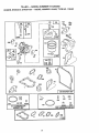
Your new tiller has been assembled at the
factory with exception of those parts left
unassembled for shipping purposes, To
ensure safe and proper operation of your
tiller all parts and hardware you assemble
must be tightened securel Y. Use the correct tools as necessary to insure proper
tightness.
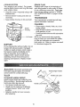
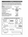
"These accessories were available when the tiller was purchased. "[hey are also available at most Sears Retail outlets and Service Centers. Most Sears Stores can order
repair parts for you when you provide the model number of your tiller.
ENGINE
MUFFLER
AIR FILTF_R
GAf_ CAN
ENGINE OIL I STABILIZER
TILLER PERFORMANCE
]SLLER MAINTENANCE
BELT ...........
,i
i,
,,,
,,,,
,,,,
,',,,'TINES
......
,,i,, ,,,,,,,,,,,,,
SHEAR PIN
HAIRPIN CLIP
,...................
4
?
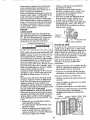
Your new tiller has been assembled at the factory with exception of those parts left
unassembled for shipping purposes. To ensure safe and proper operation of your tiller
all parts and hardware you assemble must be tightened securely. Use the correct too_s
as necessary to insure proper tightness.
TOOLS
REQUIRED
FRONT
FOR ASSEMBLY
A socket wrench set will make assembly
easier. Standard wrench sizes are listed.
(I) Utility knife
(l) Wire cutter
(1) Tire pressure gauge
(1) Screwdriver
(t) Pair of pliers
(1) 9/I6" wrench
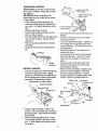
OPERATOR'S
POSITION
When right or left hand is mentioned
in
this manual, it means when you are in
the operating
position (standing behind
tiller handles).
RIGHT
LEFT
OPERATOR'S
POSITION
G
(2) Handle
Locks
(1) Carriage Bolt
3/8-16 UNC x 1 Gr, 5
(t) Center Locknut
3/8d 6 UNC
(1) Cable Clip
(2) Hairpin Clips
(1) Pivot Bolt
3/8-t6 UNC Grade 5
(I) Flat Washer
13/32 x t x 11 Ga.
©
Extra
Shear
Pins & Clips
(1) Handle
Lock Lever
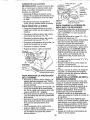
UNPACKING
CARTON
_kCAUTION:
Be careful of exposed staples when handling or disposing of cartoning material.
IMPORTANT:When
unpacking and
assembling tiller, be careful not to stretch
or kink cables.
o While holding handle assembly, cut
cable ties securing handle assembly to
top frame. Let handle assembly rest on
tiller_
• Remove top frame of carton.
o Slowty ease handle assembly up and
place on top of carton.
° Cut down right hand front and right hand
rear corners of carton, lay side carton
wall down.
o Remove packing material from handle
assembly.
o Separate shift rod from handle assembly.
Shift Rod
Assernbly
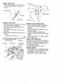
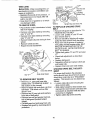
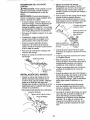
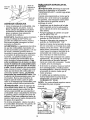
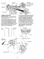
INSTALL
HANDLE
° Insert one handle lock (,with teeth facing
outward) in gearcase notch. (Apply
grease on smooth side of handle lock to
aid in keeping lock in place until handle
assembly is lowered into position.)
, Handle AsserfibEy
"UP" Position
"_,.
Tighten handle lock
.''_.. ever to hold
Loosen Handle
Lever to Move
o Insert pivot bolt in front part of plate and
tighten.
° Cut down remaining corners of carton
and lay panels flat.
o Lower the handle assembly. Tighten nut
on carriage bolt so handle moves with
some resistance. This will allow for easier adjustment.
o Place flat washer on threaded end of
handle lock lever.
- Insert handle lock lever through handle
base and gearcase. Screw in handle
lock lever just enough to hold lever in
place.
o insert second handle lock (with teeth
inward) in the slot of the handle base
(just inside of washer),
o Raise handle assembly to highest position and securely tighten handle lock
lever by rotating clockwise,
Leaving
handle assembly in highest position will
make it easier to connect shift rod.
Handle Lock
Viewed from r.h. side of tiller
Gearcase
\
Flat Washer
Handle Lock
dandle Assembly
Gearcase Notch
Handle Lock
Slot
Rear Cartridge
Bolt
Pivot Bolt
Handle
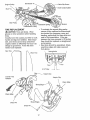
° Grasp handle assembly. Hold in "up"
position. Be sure handle lock remains in
gearcase notch. Slide handle assembly
into position.
• Rotate handle assembly down. Insert
rear carriage bolt first, with head of bolt
on LH. side of tiller and loosely assemble Iocknut.
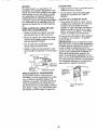
INSERT CABLE CLIP
o Insert plastic cable clip into hole on the
back of handle column. Push cables
into clip.
Shift
Handle Column
Cables
Cable Clip
CONNECT SHIFT ROD
* Insert end of shift rod farthest from bend
into hole of shift lever indicator°
o Insert hairpin clip through hole of shift
rod to secure.
o Insert other end of shift rod into hole in
shift lever.
° Insert second hairpin clip through hole of
shift rod.
Attach this end to shift lever...._
Attach this
t,,,,u
End To shift
Lever Indicator
Shift Rod
Hairpin Clip
\
Shift Rod
Shift Lever
Indicator
Shift Rod
REMOVE TILLER FROM CRATE
,, Adjust handle assemby to lowest position. Be sure lock lever is tightened
securely.
o Make sure shift lever indicator is in "N"
(neutral) position,
o Tilt tiller forward by lifting handle°
Separate cardboard cover from leveling
shield.
o Rotate tiller handle to the right and pull
tiller out of carton.
CHECK TIRE PRESSURE
The tires on your unit were overinflated at
the factory for shipping purposes. Correct
and equal tire pressure is important for
best tilling performance,
° Reduce tire pressure to 20 PSL
HANDLE HEIGHT
° Handle height may be adjusted to better
suit operator. (See "TO ADJUST HANDLE HEIGHT" in the Service and
Adjustments section of this manual).
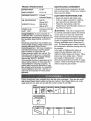
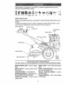
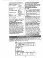
These symbols may appear on your Tiller or in literature supplied with the product.
Learn and understandtheir meaning,
RUN
ENGINE
OH
KNOW
YOUR
READ THIS
TILLER.
ENGINE
FA_T
SLOW
CHOKE
FUEL
O_L
_,TOP O
OFF
TILLER
OWNER'S
MANUALAND
SAFETY
RULES
BEFORE
OPERATING
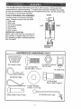
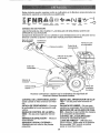
Compare
the illustrations
with your tiller to familiarize
yourself with the location
ous controls and adjustments,
Save this manual for future reference.
Drive Control Bar
YOUR
of vari-
Throttle Control
Lever'
Fuel Shut-Off
valve
Choke Control
Shift Lever Indicator
Depth Stake
Leveling
Recoil
Starter
Handle
Outer Side Shield
MEETS ANSI SAFETY REQUIREMENTS
Our tillers conform to the safety standards of the American National Standards
DRIVE CONTROL
tines.
BAR - Used to engage
DEPTH STAKE - Controls depth at which
tiller will dig.
LEVELING SHIELD - Levels tilled soil.
OUTER SIDE SHIELD - Adjustable to protect small plants from being buried.
THROTTLE CONTROL - Used to control
engine speed.
institute,
SHIFT LEVER - Used to shift transmission
gears.
SHIFT LEVER INDICATOR
- Shows which
gear the transmission is in.
RECOIL STARTER HANDLE
- Used to
start the engine.
CHOKE CONTROL
a cold engine.
- Used
when starting
The operation of any tiller can result in foreign objects
which can result in severe eye damage° Always wear
shields before starting your tiller and while tilling. We
vision safety mask over spectacles or standard safety
HOW TO USE YOUR
TILLER
thrown into the eyes,
safety glasses or eye
recommend a wide
glasses°
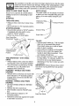
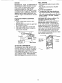
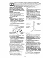
DEPTH STAKE
The depth stake can be raised or lowered
to allow you more versatile tilling and cultivating, or to more easily transport your
tiller,
Know how to operate all controls before
adding fuel and oil or attempting to start
engine°
STOPPING
TINES AND DRIVE
Shallowest Tilling ...._
(Cultivating)
, Release drive control bar to stop movement.,
• Move shift lever to "N" (neutral) position°
STOPPING ENGINE
_" Transport Position
Deepest Tilling
o Move throttle control to "STOP" position.
If equipped with stop switch, move
switch to "STOP" position.
° Never use choke to stop engine.
Drive Control Bar
"ENGAGED" Position
Shift Lever
Depth Stake ,_
TILLING
° Release depth stake pin. Pull the depth
stake up for increased tilling depth.
Place depth stake pin in hole of depth
stake to lock in position.
o Place shift lever indicator in till position.
• Hold the drive control bar against the
handle to start tilling movement. Tines
and wheels will both turn.
o Move throttle control to "FAST" position
for deep tilling. To cultivate, throttle control can be set at any desired speed,
depending on how fast or slow you wish
to cultivate.
IMPORTANT: Always release drive control
bar before moving shift lever into another
position.
Drive
Bar
"DISENGAGED"
Position
Thr&le
TINE OPERATION - WITH WHEEL
DRIVE
• Always release drive control bar before
moving shift lever into another position.
• line movement is achieved by moving
shift lever to ( _ ) til! position and
engaging drive control bar,
FORWARD - WHEELS ONLY/TINES
STOPPED
o Release drive control bar and move shift
lever indicator to "F" (forward) position.
Engage drive control bar and tiller wil!
move forward,
REVERSE - WHEELS ONLY/TINES
STOPPED
° DO NOT STAND DIRECTLY BEHIND
TILLER°
o Release the drive control bar.
o Move throttle control to "SLOW" position.
o Move shift lever indicator to "R"
(reverse) position_
o Hold drive control bar against the handle
to start tiller movement.
Depth Stake Pin
Position
"Locked"
Position
Nut "B"
Nut "A"
Outer Side Shield
9
TURNING
o Release the drive control bar.
= Move throttle control to "SLOW" position.
CHECK ENGINE OIL LEVEL
° The engine in your unit has been
shipped, from the factory,, already filled
with SAE 30 summer weight oil.
• With engine level, clean area around oil
filler plug and remove plug.
° Engine oil should be to point of overflowing when engine is level. For approximate capacity see "PRODUCT SPECIFICATIONS" on page 4 of this manual.
All oil must meet A.P.I. Service
Classification SF, SG or SH.
• For cold weather operation you should
change oil for: easier starting (See oil
viscosity chart in the Maintenance section of this manual).
° To change engine oil, see the
Maintenance section in this manual.
= Place shift lever indicator in "F" (forward)
position. Tines will not turn°
o Lift handle to raise tines out of ground.
o Swing the handle in the opposite direction you wish to turn, being careful to
keep feet and legs away from tines.
° When you have completed your turnaround, release the drive control bar and
lower handle. Place shift lever in till
position and move throttle control to desired speed_ To begin tilling, hold drive
control bar against the handle.
OUTER SIDE SHIELDS
The back edges of the outer side shields
are slotted so that the shields can be
raised for deep tilling and lowered for shallow tilling to protect small plants from
being burJed_ Loosen nut "A" in slot and
nut "B". Move shield to desired position
(both sides). Retighten nuts,
oil
Oil Level
Filler
Plug
TO TRANSPORT
,_kCAUTION; Before lifting or transporting, allow tiller engine and muffler to cool.
Disconnect spark plug wire. Drain gasoline from fuel tank.
AROUND THE YARD
o Release the depth stake pin. Move the
depth stake down to the top hole for
transporting the tiller. Place depth stake
pin in hole of depth stake to lock in position. This prevents tines from scuffing
the ground.
o Place shift lever indicator in "F" (forward)
position for transporting.
o Hold the drive control bar against the
handle to start filler movement. Tines
will not turn.
° Move throttle control to desired speed.
AROUND TOWN
° Disconnect spark plug wire_
° Drain fuel tank.
° Transport in upright position to prevent
oil leakage.
BEFORE
STARTING
ENGINE
IMPORTANT: Be very careful not to allow
dirt to enter the engine when checking or
adding oil or fuel. Use clean oil and fuel
and store in approved, clean, covered containers. Use clean fill funnels.
Oil Drain Plug
ADD GASOLINE
o Fill fuel tank° Use fresh, clean, regular'
unleaded gasoline. (Use of leaded
gasoline will increase carbon and lead
oxide deposits and reduce valve life.
IMPORTANT: When operating in temperatures below 32°F (0°C), use fresh, clean,
winter grade gasoline to help insure good
C_dAweather starting.
RNING: Experience indicates that
alcohol blended fuels (called gasohol or
using ethanol or methanol) can attract
moisture which leads to separation and
formation of acids during storage, Acidic
gas can damage the fuel system of an
engine while in storage. To avoid engine
problems, the fuel system should be
emptied before storage of 30 days or
longer. Drain the gas tank, start the
engine and let it run until the fuel lines and
carburetor are empty. Use fresh fuel next
season. See Storage section of this manual for additional information_ Never use
engine or carburetor cleaner products in
the fuel tank or permanent damage may
occur.
10
NOTE: A warm engine requires less choking to start.
- Move throttle control to desired running
position..
. Allow engine to warm up for a few minutes before engaging tines.
NOTE: If at a high altitude (3000 feet) or
in cold temperatures (below 32°F), the carburetor fuel mixture may need to be
adjusted for best engine performance.
See "TO ADJUST CARBURETOR"
in the
Service and Adjustments section of this
manual.
NOTE; If engine does not start, see troubleshooting points.
TILLING
HINTS
,_CAUTION:
Fill to within 1/2 inch of top
of fuel tank to prevent spills and to allow
for fuel expansion_ If gasoline is accidentally spilled, move machine away from
area of spill Avoid creating any source of
ignition until gasoline vapors have disappeared.
Do not overfill. Wipe off any spilled oil or
fuel. Do not store, spill or use gasoline
near an open flame.
TO START ENGINE
.4{&CAUTION: Keep tine control in "OFF"
position when starting engine°
When starting engine for the first time or if
engine has run out of fuel, it will take extra
pulls of the recoil starter to move fuel from
the tank to the engine.
o Make sure spark plug wire is properly
connected and access cover is completely closed to create proper seal.
o Move shift lever indicator to "N" (neutral)
position.
• Place throttle control in "FAST" position.
o Turn fuel shut-off valve to "ON" position.
o Push stop switch to "ON" position
o Move choke control to full "CHOKE"
position. Grasp recoil starter handle with
one hand and grasp tiller handle with
other hands Pull rope out slowly until
engine reaches start of compression
cycle (rope will pull slightly harder at this
point).
° Pull recoil starter handle quickly. Do not
let starter handle snap back against
starter. Repeat if necessary.
Choke Contro,
,_CAUTION:
Until you are accustomed to
handling your tiller, start actual field use
with throttle in slow position (mid-way
between "FAST" and "IDLE")o
• Tilling is digging into, turning over, and
breaking up packed soil before planting.
Loose, unpacked soil helps root growth.
Best tilling depth is 4" to 6". A tiller will
also clear the soil of unwanted vegetation. The decomposition of this vegetable matter enriches the soil.
Depending on the climate (rainfall and
wind), it may be advisable to till the soil
at the end of the growing season to further condition the soil.
o Soil conditions are important for proper
tilling. Tines wil! not readily penetrate
dry, hard soil which may contribute to
excessive bounce and difficult handling
of your tiller. Hard soil should be moistened before tilling; however, extremely
wet soil will "ball-up" or clump during tilling. Wait until the soil is less wet in order
to achieve the best results. When tilling
in the fall, remove vines and long grass
to prevent them from wrapping around
the tine shaft and slowing your tilling
operation.
o You will find tilling much easier if you
leave a row untilled between passes.
Then go back between tilled rows. There
are two reasons for doing this° First,
wide turns are much easier to negotiate
than about-faces. Second, the tiller
won't be pulling itself, and you, toward
the row next to it.
o Do not lean on handle. This takes
weight off the wheels and reduces traction.
_
Switch
CounterClockwise_'-_
Fuel shut-off Valve
If engine fires but does not start, move
choke control to half choke position. Pul!
recoil starter handle until engine starts°
o When engine starts, slowly move choke
control to "RUN" position as engine
warms up.
1!
To get through a really tough sectionof
sod or hard ground, apply upward pres-
TINE SHEAR PiNS
The tine assemblies on your tiller are
secured to the tine shaft with shear pins
(See "TINE REPLACEMENT"
in the
Service and Adjustments section of this
manual).
If the tiller is unusually overloaded or
jammed, the shear pins are designed to
break before internal damage occurs to
the transmission.
o if shear pin(s) break, replace only with
those shown in the Repair' Parts section
of this manual.
sure on handle or lower the depth stake.
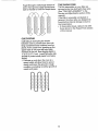
CULTIVATING
Cultivating is destroying the weeds
between rows to prevent them from robbing nourishment and moisture from the
plants. At the same time, breaking up the
upper layer of soil crust will help retain
moisture in the soil. Best digging depth is
1" to 3" (2.5-7.5 cm). Lower the outer side
shields to protect small plants from being
buded,
• Cultivate up and down the rows at a
speed which will al!ow tines to uproot
weeds and leave the ground in rough
condition, promoting no further growth of
weeds and grass,
0 0 010 0
o o 0!o 0
0 00lO
0
0 0 040 O;
12
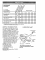
MAINTENANCE
SCHEDULE
#
,.
FILL IN DATES
AS YOU COMPLETE
REGULAR SERVICE
Check Engine Oit Lever
SERVICE
_
6/
Change Engine Oil
t_1,2
i
Oil Pivot Points
DATES
.......................
6/
Inspect Spark Attester/Muffler
!_
Inspect Air Screen
Clean or Replace Air Cleaner Cartridge
6,/2
Clean Engine Cylinder Fins
Replace Spark Plug
I - Change more o_'ten when operating under a heavy load or in high ambient temperatures
2 - Service more often when operating in dirty or dusty condilions
GENERAL
RECOMMENDATIONS
The warranty on this tiller does not cover
items that have been subjected to operatot abuse or negligence. To receive full
value from the warranty, the operator must
maintain tiller as instructed in this manual.
Some adjustments will need to be made
periodically to properly maintain your tiller.
All adjustments in the Service and
Adjustments section of this manual should
be checked at least once each season.
• Once a year you should replace the
spark plug, clean or replace air filter, and
check tines and belts for wear. A new
spark plug and clean air filter assure
proper air-fuel mixture and help your
engine run better and last longer.
BEFORE EACH USE
• Check engine oil level.
• Checktine operation.
o Check for loose fasteners.
LUBRICATION
Keep unit well lubricated (See "LUBRICATION CHART").
LUBRICATION
CHART
* Throttle Control
Depth Stake Pin
-%
* Leveling
Shield
Hinges
* Idler Bracket
Wheel Hub
* SAE 30 OR 5W-30 MOTOR OIL
** REFER TO MAINTENANCE
"ENGINE"
SECTION
13
Disconnectspark plug wire before performing any maintenance (except carburetor adjustment)to prevent accidentalstarting of engine.
Prevent fires! Keep the engine free of
grass, leaves, spilled oil, or fuel. Remove
fuel from tank before tipping unit for' maintenance. Clean muffler area of all grass,
dirt, and debris.
• Refill engine with oil. See "CHECK
ENGINE OIL LEVEL" in the Operatioq
section of this manual.
OII Drain Plug
Oil Level
Do not touch hot muffler or cylinder fins as
contact may cause burns.
ENGINE
LUBRICATION
Use only high quality detergent oil rated
with APt service classification SF, SG or
SH_ Select the oil's SAE viscosity grade
according to your expected temperature.
NOTE: Although multi-viscosity oils (5W30, 10W-30, etc.) improve starting in cold
weather; these multi-viscosity oils will
result in increased oil consumption when
used above 32°F (0°C). Check your
engine oil level more frequently to avoid
possible engine damage from running low
on oil.
Change the oil after every 50 hours of
operation or at least once a year if the tiller
is not used for 50 hours in one year:
Check the crankcase oil level before starting the engine and after each five (5)
hours of continuous use. Add SAE 30
motor oil or equivalent. Tighten oil filler
plug securely each time you check the oil
level.
TO CHANGE ENGINE OIL
Determine temperature range expected
before oil change. All oil must meet API
service classification SF, SG or SH.
o Be sure tiller is on level surface.
- Oil will drain more freely when warm.
= Use a funnel to prevent oil spill on tiller,
and catch oil in a suitable container.
Remove drain plug.
• Tip tiller forward to drain oil.
• After oil has drained completely, replace
oil drain plug and tighten securely.
° Remove oil filler plug. Be careful not to
allow dirt to enter the engine.
Oil Filler Plug
AIR FILTER
Your engine will not run propedy using a
dirty air filter: Clean the foam pre-cleaner
after every 50 hours of operation or every
season. Service paper cartridge every
100 hours of operation or every season,
whichever occurs first°
Service air cleaner more often under dusty
conditions°
o Loosen air cleaner cover screws.
Remove cover and air cleaner assembly
from base°
. Remove air cleaner asssembly from
inside cover and disassemble.
TO SERVICE PRE-CLEANER
= Wash it in liquid detergent and water:
° Squeeze it dry in a clean cloth.
= Saturate it in engine oil. Wrap it in
clean, absorbent cloth and squeeze to
remove excess oil.
Pre-Cleaner
Cover
Base
fill
;over Screws
"TO SERVICE
CARTRIDGE
o Gently tap the flat side of the paper cartridge to dislodge dirt. Do not wash the
paper cartridge or use pressurized air,
as this will damage the cartridge.
Replace a dirty, bent, or damaged cartridge.
• Re-assernble retainer on pre-cfeaner
and cartridge (screen side of pre-cleaner
toward cartridge pleats). Place assembly into cover.
°
Insert tabs on cover into slots in base
and tighten cover screws securely°
14
COOLING SYSTEM
Your engine is air cooled. For proper
engine performance and long life keep
your engine clean°
o Clean air screen frequently using a stiffbristled brush_
• Remove blower housing and clean as
necessary.
° Keep cylinder fins free of dirt and chaff_
SPARK
PLUG
Replace spark plugs at the beginning of
each tilling season or after every 50 hours
of use, whichever comes first. Spark plug
type and gap setting is shown in "PRODUCT SPECIFICATIONS"
on page 4 of this
manual,,
TRANSMISSION
Your transmission
require lubrication
is sealed and will only
if serviced.
CLEANING
o Clean engine, wheels, finish, etc. of all
foreign matter°
o Keep finished surfaces and wheels free
of all gasoline, oil, etco
o Protect painted surfaces with automotive
type wax_
We do not recommend using a garden
hose to clean your unit unless the muffler,
air filter and carburetor are covered to
keep water out° Water in engine can result
in a shortened engine life,
Blower
Housing
Air Screen
MUFFLER
Do not operate tiller without muffler. Do not
tamper with exhaust system. Damaged
mufflers or spark arresters could create a
fire hazard. Inspect periodically and replace if necessary° If your engine is
equipped with a spark arrester screen
assembly, remove every 50 hours for
cleaning and inspection_ Replace if damaged°
,&CAUTION:
Disconnect spark plug wire
from spark plug and place wire where it
cannot come into contact with plug.
Handle (High) Position
TILLER
TO ADJUST HANDLE HEIGHT
Select handle height best suited for your
tiIling conditions. Handle height will be different when tiller digs into soil.
o First loosen handle lock lever.
° Handle can be positioned at different
settings between "HIGH" and "LOW"
positions.
o Retighten handle lock lever securely
after adjusting.
Handle Lock Lever
Handle (Low) Position
15
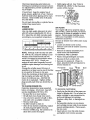
TIIRE CARE
Belt Guard
_CAUTiON:
When mounting tires, unless beads are seated, overinflation can
cause an explosion.
o Maintain 20 pounds of tire pressure, tf
tire pressures are not equal, tiller will
pull to one side_
o Keep tires free of gasoline or oi! which
can damage rubber:
TO REMOVE WHEEL
Hex Nut and
Washer
(Located
Behind Tire)
Cap Nut
and
Washer
and Clevis Pin
Hairl
TO REPLACE
GROUND
DRIVE
BELT
• Remove belt guard as described it1 '%0
REMOVE BELT GUARD".
° Loosen bett guides "A" and "B" and
also remove stud "C"o
° Remove old belt by slipping off engine
pulley first then remove from the pulley.
° Place new belt in groove of transmission pulley and into engine pulley_ BELT
MUST BE IN GROOVE ON TOP OF
IDLER PULLEY_ NOTE POSITION OF
BELT TO GUIDES.
o Tighten belt guides "A" and "B" and stud
o Place blocks under transmission to keep
tiller from tipping.
= Remove outer side shield by removing
nuts "A" and "B".
= Remove inner side shield by removing
nuts "C" and "D",
• Remove hairpin clip and clevis pin from
wheel.
• Remove wheel and tire.
o Repair tire and reassemble.
Clevis
_C
t_.
• Check belt adjustment as described
below.
o Replace belt guard.
o Reposition wheel and replace clevis pin
and hairpin clip.
° Replace inner and outer side shields.
Hairpin
Clip
Nut "B"
Nut "A
GROUND
Inner Side Shield
Outer Side Shield
TO REMOVE
BELT GUARD
° Remove L.H. outer and inner side
shields (See 'q'O REMOVE WHEEL" in
this section of this manual).
° Remove hairpin clip and clevis pin from
left wheel. Pull wheel out from tiller
about 1 inch.
o Remove two (2) cap nuts and washers
frorn side of belt guard.
o Remove hex nut and washer from bottom of belt guard (located behind
wheel).
° Pull belt guard out and away from unit,
° Replace belt guard by reversing above
procedure_
,
DRIVE
BELT
ADJUST-
MENT
For proper belt tension, the extension
spring should have about 5/8 inch stretch
when drive control bar is in "ENGAGED"
position. This tension can be attained as
follows:
• Loosen cable ctip screw securing tile
drive control cable.
• Slide cable forward for less tension and
rearward for more tension until about 5/8
inch stretch is obtained while the drive
control bar is engaged.
• Tighten cable clip screw securely.
16
Engine Pulley
Belt Guide "A"
Clip Screw
Drive Control Cable
Stud "C',_,
Idler Pulley
Fension
Extension Spring
Transmission
TINE
Pulley
REPLACEMENT
,_kCAUTION: Tines are sharp. Wear
gloves or other protection when handling
tines.
A badly worn tine causes your tiller to work
harder and dig more shallow. Most important, worn tines cannot chop and shred
organic matter as effectively nor bury it as
deeply as good tines. A tine this worn
needs to be replaced.
° To maintain the superb tilling performance of this machine the tines should
be checked for sharpness, wear, and
bending, particularly the tines which are
next to the transmission.
If the gap
between the tines exceeds 3-1/2 inches
they should be replaced or straightened
as necessary.
° New tines should be assembled. Sharpened tine edges will rotate rearward
from above.
New Tine
Tine
transmission_
3-1/2" Max
Counter Tine
Rotation
Hairpin Clip
Sharp Edge
Sharp Edge
Shear Pin
Shear Pin
17
ENGBNE
FINAL SETTING
Maintenance, repair, or replacement of
the emission control devices and systems, which are being done at the
customers expense, may be performed by any non-road engine repair
establishment or individual. Warranty
repairs must be performed by an authorized engine manufacturer's service
outlet.
° Start engine and allow to warm for five
minutes.
o With throttle control lever in "SLOW"
position°
IDLE RPM ADJUSTMENT
TO ADJUST
CABLE
THROTTLE
CONTROL
• Loosen cable clamp screw to allow
cable to move.
= Move throttle control lever on upper handle to "FAST" position.
° Pull throttle cable out to end of travel
° Hold cable in this position and tighten
clamp screw securely.
= To adjust idle RPM, rotate throttle linkage counterclockwise and hold against
stop while adjusting idle speed adjusting
screw to obtain t750 RPM. Release
throttle linkage.
High speed stop is factory adjusted. Do
not adjust or damage may result.
IMPORTANT: Never tamper with the engine governor, which is factory set for
proper engine speed, overspeeding the
engine above the factory high speed setting can be dangerous. If you think the
engine-governed
high speed needs adjusting, contact your nearest authorized service center/department,
which has the
proper equipment and experience to make
any necessary adjustments.
Idle Speed
Adjustin!
Screw
Cable
Linkage
Clamp Screw
TO ADJUST
CARBURETOR
The carburetor has a high speed jet and
has been preset at the factory and adjustment should not be necessary. However,
minor adjustments may be required to
compensate for differences in fuel, temper_
ature, altitude or load. tf the carburetor
does need adjustment, proceed as follows.
Valve
18
Immediately prepareyour tiller for storage
at the end of the season or if the unit will
not be used for 30 days or more°
_kCAUTION:
Never store the tiller with
gasoline in the tank inside a building
where fumes may reach an open flame or
spark. Allow the engine to cool before
storing in any enclosure°
TILLER
o Clean entire tiller (See "CLEANING" in
the Maintenance section of this manual),,
o Inspect and replace belts, if necessary
(See belt replacement instructions in the
Service and Adjustments section of this
manual).
° Lubricate as shown in the Maintenance
section of this manual,
o Be sure that all nuts, bolts and screws
are securely fastened, Inspect moving
parts for damage, breakage and wear.
Replace if necessary.
o Touch up all rusted or chipped paint surfaces; sand lightly before painting.
ENGINE
FUEL SYSTEM
IMPORTANT: It is important to prevent
gum deposits from forming in essential fuel
system parts such as the carburetor, fuel
filter, fuel hose, or tank during storage.
also, experience indicates that alcohol
btended fuels (called gasohol or using
ethanol or methanol) can attract moisture
which leads to separation and formation of
acids during storage. Acidic gas can damage the fuel system of an engine while in
storage.
o Drain the fuel tank.
= Start the engine and let it run until the
fuel lines and carburetor are empty.
o Never use engine or carburetor cleaner
products in the fuel tank or permanent
damage may occur.
o Use fresh fuel next season.
NOTE: Fuel stabilizer is an acceptable
alternative in minimizing the formation of
fue! gum deposits during storage. Add stabilizer to gasoline in fuel tank or storage
container, Always follow the mix ratio
found on stabilizer container. Run engine
at least I0 minutes after adding stabilizer
to allow the stabilizer to reach the carburetor, Do net drain the gas tank and carburetor if using fuel stabilizer.
ENGINE
OIL
Drain oil (with engine warm) and replace
with clean oil. (See "ENGINE" in the
Maintenance section of this manual),
CYLINDER(S)
• Remove spark plug.
o Pour t ounce (29 ml) of oil through
spark plug hole into cylinder.
• Pull starter handle slowly several times
to distribute oil.
• Replace with new spark plug.
OTHER
o Do not store gasoline from one season
to another,
o Replace your gasoline can if your can
starts to rust. Rust and/or dirt in your
gasoline will cause problems.
• If possible, store your unit indoors and
cover it to give protection from dust and
dirt.
o Cover your unit with a suitable protective
cover that does not retain moisture° Do
not use plastic° Plastic cannot breathe
which allows condensation to form and
will cause your unit to rusL
IMPORTANT: Never cover tiller while
engine and exhaust areas are still warm.
19
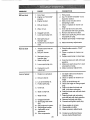
Will not start
CORRECTION
CAUSE
PROBLEM
1 Fill fuel tank.
2. See "TO START ENGINE" inthe
1o Out of fuel.
2. Engine riot"CHOKED"
properly°
3. Engine flooded°
4
Operation section.
3. Wait several minutes before
Dirty air cleaner
5. Water in fuel
6. Clogged fuel tank.
7. Loose spark plug wire
Hard to start
4
attempting to start.
Clean or replace air cleaner car
5.
tridge
Drain fuel tank and carburetor,
and refill tank with fresh gasoline.
6. Remove fuel tank and clean°
7. Make sure spark plug wire is seat
ed properly on plug.
Replace spark plug or adjust gap°
8_ Bad spark plug or
improper gap
9_ Carburetor out of adjustmerit.
8
1. Throttle control not set
1. Place throttle control in "FAST"
properly.
2. Dirty air cleaner:
2
3. Bad spark plug or
improper gap.
4. Stale or dirty fuel
4
9. Make necessary adjustments_
position.
Clean or replace air cleaner car
tddgeo
3. Replace spark plug or adjust gap
5. Loose spark plug wire
6_ Carburetor out of.
Drain fuel tank and refill with fresh
gasoline.
5. Make sure spark plug wire is seat
ed properly on plug
6. Make necessary adjustments
adjustment,
Loss of power
2. Dirty air cleaner
Set depth stake and wheels for
shallower tilling,
2. Clean or replace air cleaner car
3. Low oil level/dirty oil.
4. Faulty spark plug.
tridge.
Check oil level/change oil.
4. Clean and regap or change spark
5. Oil in fuel
5.
plug.
Drain and clean
6. Stale ordirtyfueL
6.
refill, and clean carburetor°
Drain fuel tank and refill with fresh
7. Water in fueL
7.
gasoline,
Drain fuel tank and carburetor,
1. Engine is ovedoadedo
8. Clogged fuel tank.
9. Spark plug wire loose,
wire.
10. Dirty engine air screen.
11. Dirtylclogged muffler.
12. Carburetor out of
13.
adjustment.
Poor compression.
fuel tank and
and refill tank with fresh gasoline.
8. Remove fuel tank and clean.
9. Connect and tighten spark plug
t0. Clean engine air screen.
11. Clean/replace muffler.
12. Make necessary adjustments.
13o Contact an authorized
Sears
Service CentedDepartment.
2O
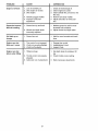
PROBLEM
Engine overheats
CAUSE
CORRECTION
1, Low oil level/dirty oil,
2. Dirty engine air screen°
3, Dirty engine_
t. Check oil level/change oil,
2. Clean engine air screen.
3o Clean cylinder fins, air screen, muf
tier area.
4. Partially plugged muffler,
5_ Improper carburetor
adjustment,,
4. Remove and clean muffler.
1. Ground too dry and hard,
t.
2, Wheels and depth stake
incorrectly adjusted.
2. Adjust wheels and depth stake.
Soil balls up or
clumps
1, Ground too wet,
I.
Engine runs but
tiller won't move
1,, Fine control is not engaged,
2o V-belt not correctly adjusted.,
3, V-belt is off pulley(s),
1. Engage tine control
2_ Inspect/adjust V-beE
3. Inspect V-belt.
Engine runs but
labors when tilling
1. Tilling too deep.
1. Set depth stake for shallower till
ing,
2. Check throttle control setting_
Excessive bounce/
5. Adjust carburetor to richer posi
tion_
difficult handling
2. Throttle control not properly
adjusted.
3o Carburetor out of adjustment,
21
Moisten ground or wait for more
favorable soi! conditions.
Wait for more favorable soi! condi
tions,,
3, Make necessary adjustments
Garantfa ...............................................22
Reglasde Seguridad.............................
22
Especificacionesdel producto...............
24
Montaje.................................................25
Operaci6n ...................,................23 & 28
Mantenimiento......................................33
Servicio y Ajustes .................................. 35
Almacenamiento .......................... 23 & 39
Identificaci6n de Problemas ................. 40
Vea et manual Ingl6s del due5o ....... Back
Cover
GARANTIA LIMITADA DE DOS ANOS PARA LA CULITVADORA CRAFTSMAN
Por dos (2) aSos, a partir de la fecha de compra, cuando esta Cultivadora Craftsman se
mantenga, lubrique y afine segQn las instrucciones para la operacion y el mantenimiento en el manual del due_o, Sears reparar_, gratis, todo defecto en el material y la mano
de obra.
Esta Garantfa no cubre:
o Articulos que se desgastan durante el uso normal tales como los brazos, las bujfas,
los filtros de aire y las correas.
- Reparaciones necesarias debido al abuso o a la negligencia del operador; incluy_ndose a los ciguefiales doblados y a la falta de mantenimiento del equipo segQn las
instrucciones que se incluyen en el manual det due5o.
o Si la Cultivadora Craftsman se usa para fines de arriendo, esta garantia se aplica
solamente por treinta (30) treintad/as a partir de la fecha de compra.
El Servicio de Garantia esta disponible al devolver la cultivadora Craftsman al
centor/departmento
de servicio Sears m_s cercano en los Estados Unidoso Esta
Garantia se aplica colamente mentras el producto este en uso en tos Estados Unidoso
Esta Garant{a le otorga derechos legates especfficos, y puede que tambi_n tenga otros
derechos que varian de estado a estado.
SEARS, ROEBUCK AND CO., D/817WA, HOFFMAN ESTATES, IL 60179
ENTRENAIVlIIENTO
o No opere et equipo sin usar ropa exterior adecuada. Use zapatos que mejoren
et equilibrio en superficies resbalosas.
o Maneje el combustible con cuidado
pues es muy inflamable.
Use un envase de combustible aprobado,.
• Lea el Manual det Due5o cuidadosamente_ Familiar/cese cornpletamente
con los controles y con el uso adecuado
del equipo. Sepa c6mo parar la unidad y
desenganchar los controles r_pidamente.
° Nunca permita que los niSos operen el
equipo. Nunca permita que los adultos
operen el equipo sin los conocimientos
adecuados.
o Nunca a5ada combustible a un motor en
funcionamiento
o caliente.
o Llene el estanque de combustible afuera
con mucho cuidado. Nunca tlene el
estanque de combustible en un recinto
cerrado.
• Mantenga et Area de operaci6n despejada de personas, especialmente niF,os
pequeSos y animales dom_sticos.
o Vuelva a colocar la tapa del dep6sito de
gasolina en forma segura y limpie el
combustible derramado antes de volver
a arrancar.
PREPARACION
o Inspeccione cuidadosamente
el &tea en
donde se va usar el equipo y remueva
los objetos extraSos.
Use cordones de extensi6n y receptAculos, segun las especificaciones
del fabricante, para todas las unidades con
motores de impulsi6n o con rnotores de
arranque electdco.
• Desenganche todos los embragues y
cambie a neutro antes de hacer arrancar el motor.
22
Nunca_tratede hacer ningunajuste
mientrasque el motor est_ funcionando
(exceptoen los casos especificamente
recomendadospor el fabricante),
OPERACI6N
° Use solamente accesorios y aditamentos para la cultivadora aprobados por el
fabricante.
o No ponga ni tas manos ni los pies cerca
o debajo de las piezas rotatoriaso
• Tenga cuidado al cultivar en terreno
duro. Los brazos pueden quedarse
agarrados en el suelo e impulsar a la
cultivadora hacia adelante. Si esto
sucede, suelte los mangos y no restrinja
la m_quina.
o Tenga mucho cuidado cuando opere o
cruce entradas para autom6viles de
ripio, senderos o caminos_ Est6 alerta
en Io que se refiere a los peligros escondidos o al tr&ficoo No Ileve pasajeros.
= Despu6s de pegarle a un objeto
extrafio, pare el motor, remueva el alambre de la bujia, inspeccione la cultivadora cuidadosamente,
para verificar si hay
dafios, y repare el dafio antes de volver
a arrancar y operar ta cultivadora.
o Tenga cuidado para evitar resbalarse o
cae rseo
o Si la unidad empieza a vibrar anormat_
mente, pare el motor y revisela inmedi*
atamente para verificar ta causao La vibraci6n normalmente es un aviso de
problemas..
° Pare el motor cuando abandone la posici6n de operaci6n,
, Tome todas las precauciones posibles
cuando deje la m_quina desatendida.
Desenganche los brazos, cambie a neutroy pare el motor,
- Antes de limpiar, reparar e inspeccionar,
apague el motor y asegSrese que todas
las partes en movimiento se hart
detenido. Desconecte el alambre de la
bujia, y mant_ngato alejado de 6sta
para evitar el arranque pot accidenteo
Desconecte el cord6n en los motores
el6ctricos.
o No haga funcionar el motor en recintos
cerrados; los gases de escape son peligrosos.
• Nunca opere la cultivadora sin las protecciones, y las planchas adecuadas y
sin los demos dispositivos de seguridad
en su lugar.
o Mantenga a los nifios y a los animales
dom_sticos alejados.
= No sobrecargue la capacidad de la
m_.quina, tratando de cultivar a mucha
profundidad, muy r&pido.
o Nunca opere la mAquina a altas velocidades en superficies resbalosas_ Mire
hacia atr_s y tenga cuidado cuando retroceda.
° Nunca permita la presencia
dores cerca de la unidad.
• Nunca opere la cultivadora
visibilidad o luz.
sin buena
MANTENIiVIIENTO Y ALMACENAIVllENTO
° Mantenga los accesorios y aditamentos
de la mAquina en buenas condiciones
para el funcionamiento.
o Revise las clavijas de seguro, los pernos de montaje del motor y otros pernos, a intervalos frecuentes, para verificar si estAn apretados en forma segura
y asegurarse que el equipo est_ en buenas condiciones de funcionamiento.,
• Nunca guarde la m_quina con combustible en el estanque de combustible
dentro de un edificio en donde hay
fuentes de ignici6n presentes, tales
como calentadores de agua o del ambiente, secadoras de ropa u otros artefactos parecidoso Permita que se enfrfe el
motor antes de guardarlo en algt_n lugar
cerrado.
o Siempre refi6rase alas instrucciones en
la guia del operador para ver los
detalles de importancia si la cultivadora
va a ser guardada por un perfodo de
tiempo largo.
,g_PRECAUCl6N:
Siempi'e desconecte el
alambre de la bujfa y p6ngalo donde no
pueda entrar en contacto con la bujfa,
para evitar el arranque por accidente,
durante la preparaci6n, el transporte, el
ajuste o cuando se hacen reparaciones.
Z_PRECAUCt6N:
Es conocido por el
Estado de California que los gases de
escape del motor de este productor contienen quimicos los cuales a ciertos niveles, pueden ocasionar, c&ncar, defectos de
nacimiento, y otras dafios al sistema
reproductivo.
de especta23
ESPECiFtCACIONES
C--_ALLOS
DE FUERZA:
13 pulgadas
cuadradas
CAPACIDAD
4 Cuartos
DE
GASOLINA:
Sin plomo, regular
ACEITE(API-SF/SG/SH):
SAE 30
(Sobre 32°F)
SAE 5W-30
20 oz.)
RESPONSAB|LIDADES
DEL
CLIENTE
o Lea y observe las regtas de seguridad.
o Siga un programa regular de mantenimiento, cuidado y uso de su cultivadora.
= Siga las instrucciones descdtas en las
,,secci°nes "Mantenim=ento" y
Almacenamiento"
de este Manual del
Duefo.
IMPORTANTE:
Esta unidad viene equipada con un motor de combusti6n interno y
no se debe usar sobre, o cerca, de un terreno no desarrollado cubierto de bosques,
de arbustos o de c6sped, a menos que e!
sistema de escape del motor venga
equipado con un amortiguador de chispas
que cumpla con tas teyes locales o
estatales (si existen). Si se usa un amortiguador de chispas, el operador debe
mantenerlo en condiciones de trabajo eftcientes.
(Debajo 32°F)
BUJIA:
ABERTURA:
Champion
O J19LM
0,030")
DE MANTENtMJENTO
Este producto incluye un Acuerdo de
Mantenimiento Sears° PSngase en contacto con su tienda Sears m_s cercana para
informarse sobre los detalles.
5°5 HP
DESPLAZAMIENTO:
CAPACIDAD:
ACUERDO
DEL PRODUCTO
RJ19LM
FELICITACIONES
por la compra de su Cultivadora Sears. Ha
sido dise_ada, planificada y fabricada para
darle la mejor confiabilidad y el mejor
rendimiento posible.
En el caso de que se encuentre con
cualquier problema que no pueda solucionar f_cilmente, haga el favor de ponerse en contacto con su
Centro/Departamento
de Servicio Sears,
autorizado, rn_s cercano. Sears cuenta
con t_cnicos bien capacitados y competentes con herramientas adecuadas para
darle servicio o para reparar su unidad.
Haga el favor de leer y de guardar este
manual° Estas instrucciones le permitirb.n
montar y mantener su cultivadora en
!orma adecuada. Siempre observe las
REGLAS DE SEGUR1DAD/'
En el estado de California, !,atey exige 1o
anterior (SecciSn 4442 del 'California
Public Resources Code" ). Otros estados
pueden contar con otras leyes parecidas.
Las leyes federales se aplican en las tierras federales. Vea a su Centre de Servicio
Autorizado Sears para los amortiguadores
de chispas. Refi6rase a la secciSn de
Partes de Repuesto en el manual Ingl6s
del dueSo para el ndirnero de la parte.
Estos accesorios estaban disponibles cuando se compr6 la cultivadora. Tambi6n est_n
disponibles en la mayorfa de las tiendas de Sears yen los centros de servicio. La mayorfa de las tiendas Sears tambi_n pueden ordenar partes de repuesto para usted, si les
proporciona el numero del modelo de su cultlvadora.
MOTOR
B_JJ_
._LENC_R
F_TRO DI_ A_R_,
LATA O_ GA!;OLIN*_
RENDIMIF-NTO DE LA CULTt'VADORA
MANTENIMIENTO DE LA CULTIVADORA
24
ACErFE D_L MOTO_
_T.I_DI_,I_DR
Su cuftivadora nueva ha sido montada en la f&brica,con la excepci6n de aquellas
partes que se dejaronsin montar por razonesde envfo. Para asegurarseque la cultivadora operar&en forma segura y adecuada,todas las partes y los artfculos de ferreterfa que monte tienen que estar apretadosen forma seguraoUse las herramientas
correctas, segt_nsea necesario, paraasegurarse de que queden apretadasen forma
segur&
HERRAMIENTASNECESARIAS PARA EL
PARTE DELANTERA
MONTAJE
Se le facilitar__ el montaje si cuenta con un
juego de llaves de tubo. Se han enumerado
los tamaSos est_ndar de las Ilaves°
(!) Cuchillo para todo uso
(1) Cortador de alambres
(1) Destornillador
(1) Medidor de presi6n de las Ilantas
(1) Par de alicates
(1) Llave de 9/16"
POSlClON DEL OPERADOR
Cuando en este manual se mencionan los
t6rminos "lado derecho" o "lado izquierdo"
se refiere a cuando usted se encuentra en
la posicidn de operaci6n (parado/a detrAs
de los mangos de fa cultivadora).
LADO
DERECHO
LADO
IZQUIERDO
POSlClON DEL
OPERADOR
G
(2) Cierres
(1) Tuerca de
seguridad
de centro
(l)Abrazadera
3/8.4 6 UNC
de cable
del mango
(1) Perno portadores
3/8-16
(2) Abrazaderas
de
UNC x 1 clase
_
(
5
"_
(1) Pemo articulado
horquilla
3/8-16
,
(1) Arandela
UNC Clase
plana
13/32 x 1 x 11 Ga.
0
Clavijade seguro
& retencion
©
(1)Palanca
25
de cierre
del mango
,._
5
DESEMPAQUE DE LA CAJA DE
CARTON
•_PRECAUCI6N:
Tenfa cuidado con las
grampas expuestas cuando maneje o
deseche los materiales de la caja de
cart6n.
IMPORTANTE: Cuando desempaque y
monte la cultivadora, tenga cuidado de no
estirar o enredar los cables.
o
° AI mismo tiempo que se sujeta et conjunto del mango, corte las ligaduras del
cable que aseguran el conjunto del
mango al bastidor superior y a ta estaca
de profundidad. Permita que el conjunto
del mango descanse en la cultivadora.
o Remueva el bastidor supedor de la caja
de cart6n.
,_,..-:;_;_,'-',_,
;',_:.
'_',,
• '-,.
° Lentamente, saque el conjunto del
mango hacia arriba y p6ngalo en la
parte superior de la caja de cartSn.
o Corte la esquina del lade derecho
delantera y la trasera de la caja de
carton, tienda en el suelo la pared lateral de la caja de cartSn.
° Remueva el material de empaque del
conjunto de! mango.
o Separe la varilla de cambio del conjunto
del mango.
Vadlla de Cambio
Conjunto de!
Mango
RNSTALACB6N
DEL MANGO
o lnserte un cierre del mango (con los
dientes mirando hacia afuera) en la
rnuesca de la caja de carnbio. (Aplique
grasa en el lade liso del cierre del
mango para ayudar a rnantenerlo en su
lugar hasta que el conjunto del mango
se baje a su posici6n.)
Vista desde el lade derecho de la cultivadora
\
Conjunto del Manfo
Muesca de la Caja de Cambio
Cierre del Mango
Agarre el conjunto del mango.
Mant6ngalo en la posici6n "arriba,,"
Asegt_rese que el cierre del mango permanezca en la muesca de la caja de
cambio. Deslice el conjunto del mango a
su posici6n.
Rote el conjunto det mango hacia abajo.
lnserte el perno portador trasero
primero, con la cabeza del perno en el
lade izquierdo de la cultivadora y ponga
sueltamente la tuerca de seguridad _
f
Conjunto del mango
Apriete ta palanca de
cierre del mango
sujetada
Suelte la palanca de
cierre del mango para
moveda
I
o Inserte el pemo de pivote de la parte
detantera de la placa y apriete en forma
segurao
o Corte las esquinas restantes del cart6n
y p6ngatas planas.
• Baje el conjunto de rnangoo Apriete la
tuerca del perno de acarreo para que el
mango pueda moverse con alguna
resistencia. Esto facilitara el ajusteo
° Ponga la arandela plana en el extreme
roscado de la palanca de cierre del
mango.
o Inserte la palanca de cierre del mango a
trav6s de la base del mango y de la caja
de engranaje. Atornille la palanca de
seguridad del mango, justo Io suficiente
come para sujetar la palanca en su
lugar.
° Inserte et segundo cierre del mango
(con los dientes hacia adentro) en la
ranura en la base del mango (justo dentro de la arandela)=
° Levante el conjunto del mango a la posici6n mas alta, y apriete la palanca de
cierre del mango, en forma segura,
rot_ndola en el sentido de las manillas
del reloj. Si se deja el conjunto del
mango en la oposici6n mas alta, ser_
mas f_cil conectar la palanca de cambios.
26
- Cierre del Mango
Caja de
Arandela Plana
Varilla de
Abrazadera
Horquilla,
Cambio_
_
Palanca de
Cierre del
de
Indicador de la
Palanca de
Cambio
Pemo
trasero
Palanca de Cambio
pivot
Base del Mane
Tuercas de Seguridad
INSERClON DE LA ABRAZADERA
DEL
CABLE
• Inserte la abrazadera del cable de pl_stico dentro del agujero en la parte
trasera de la cotumna de! mango.
Empuje los cables dentro de la
abrazadera.
Columna del
Mange
Cables
REMOCION DE LA CULTiVADORA DE
LA CAJA
, Ajuste el conjunto det mango a la posici6n la mas bajao Asegt3rese que el
mango de cierre est6 bien seguro.
• Asegerese que et indicador de la palanca de cambio est_ en la posici6n neutro
Abrazadera
del Cable
CONEXION
CAMBIO
DE LA VARILLA
DE
L_NT_"
o Incline la cultivadora hacia adelante levantando el mango. Separe la cubierta
de cart6n de la defensa de nivetaci6n.
o Rote el mango de la eultivadora a la
derecha y tfrela fuera de la caja de
cart6n.
o Inserte el extremo de la varitla de cambio que est& m&s alejado de la dobladura, en el agujero del indicador de la
palanca de cambioo
= Inserte la abrazadera de horquilla a
trav6s del agujero de la varilla de cambio para asegurarla.
o Inserte el otro extremo de la vari!la de
cambio en el agujero en la palanca de
cambio.
REVISION DE LA PRESION DE LAS
LLANTAS
Las Ilantas en su unidad se inflaron
demasiado en la f&brica por razones de
envfo. Es importante que las tlantas tengan fa misma presi6n y que _sta sea la
correcta para obtener el mejor rendimiento
en el labrado_
° Reduzca la presi6n de las Ilantas a 20
PSI.
o Inserte la segunda abrazadera de
horquilla a trav_s del agujero de la varilta de cambio.
Adjunte este extremo al
indicador de la palanca
de cambio
Adjunte este extremo a
la palanca de cambio
ALTURA DEL MANGO
• Se puede ajustar la altura del mango en
la mejor forma que le acomode al operador. (Yea "PARAAJUSTAR
LA ALTURA
DEL MANGO" en la secci6n de Servicio
y Ajustes de este manual.)
/
_,,,i_.,. ¢',,,,,, ,, ,,,_....
Varilla de cambio
27
Estossfmbolos puedenapareser sobre su cultivadoraen la literature proporcionadacon
el producto_aprenda y comprendasus significadoso
N£UTRO
REV_,S
ATT_HCI_N
O
MOTOR
ADVERTENCIA £NCENDtDO
MOTOB
R_PIDO
LE_'_rTO
ESTBAN@U
APAGADO
LACI@N
COM,
BUS'TIBL_
CONOZCA SU CULTIVADORA
LEA ESTE MANUAL DEL DUENO
OPERAR
SU CULTIVADORA
Y LAS REGLAS
DE SEGURIDAD
ANTES
DE
Compare
las ilustraciones
con su cultivadora
para familiarizarse
con la ubicaci6n
diversos controles y ajustes
Guarde este manual para futura referencia_
Barra de control
de la imp_si6n
Control de la
aceleraci6n
Palanca de cambio
Control de la
estrangulaci6n
de los
V_lvula de corte
de combustible
\
Indicador de la palanca de
Estaca de
Defensa de
Defensa lateral
exterior'
Mango del
arrancador
de culateo
t
Nuestras cultivadoras curnplen con los est#,ndares de seguridad
American National Standards Institute.
CONTROL DE LA ESTRANGULACION
Uselo cuando se hace arrancar un motor
fr/o.
ESTACA DE PROFUNDIDAD
- Controla
la profundidad a la cual excavar_ la cultivadora.
del
MANGO DEL ARRANCADOR
DE CULATEO - Se usa para hacer arrancar el
motor.
PALANCA DE CAMBIO - Se usa para
cambiar los engranajes de la transmisi6n.
INDICADOR DE LA PALANCA DE CAMBIO - Muestra en qu6 cambio de engranaje se encuentra la transmisi6n.
CONTROL DE LA ACELERACI6N
Controla la velocidad del motor.
BARRA DE CONTROL DE LA IMPULSION - Se usa para enganchar los braZOS.
DEFENSA DE NIVELACI6N
- Nivela el
suelo labrado. °
DEFENSA LATERAL EXTERIOR Ajustable parano enterrar las plantas
peque_as.
LLAVE DE PARADA - Utilizada para
parar el motor. Debe estar en la posici6n
de encendido "ON" cuando se qulere
poner en marcha el motor.
28
La operaci6n de cualquier cultivadorapuede hacer que salten objetos
extrafios dentro de sus ojos, Io que puede producir dafios graves en 6stos.
Siempre use anteojosde seguridad o protecciones para los ojos antes de
hacer arrancar su cultivadorao mientrasest6 labrando con ella,
Recomendamoset uso de la m_scara de seguridad de visi6n amplia, para
uso sobre los espejuelos o anteojos de seguridad est_ndar.
COiVlOUSAR SU CULTiVADORA
o Suelte fa barra de control de la impulsi6n.
Sepa c6mo operar todos los controles
antes de agregar combustible y aceite o
° Mueva el control de la aceteraci6n a la
antes de tratar de hacer arrancar el motor.
posici6n de "LENTO" (SLOW).
o Mueva el indicador de la palanca de
cambio a la posici6n de "R" (marcha
atr_s),
• Sujete la barra de control de la impulsi6n en contra del mango para hacer
arrancar en movimiento a la cultivadora.
ESTACA DE PROFUNDIDAD
La estaca de profundidad puede levantarse o bajarse para permitirle un labrado
m&s versatil o para facilitar el transporte
de su cultivadora.
PARADA
BRAZOS Y LA IMPULSI6N
o Suelte la barra de control de la impul_
si6n para parar el movimiento.
° Mueva fa palanca de cambio a la posici6n de neutro ("N")o
MOTOR
° Mueva el control de la aceleraci6n a la
posici6n de "PARADA" (STOP). Si
equipado con un interruptor de parada,
mueva e! interruptor a la posici6n de
"PARADA" (STOP).
o Nunca use la estrangulaci6n para parar
el motor,
Barra de control de la impulsi66n
en la posici6n
anchada"
Labrado menos ----'--_[
(Cultivadora)
profundo
Control de la
Aceleraci6n
[lil
_
Posici6n de
Transporte
Labrado M&s
Estaca de profundidad
Barra de
de la
impulsi6n en la posiciSn "Disenganchada"
Palanca de
cambio
LABRADO
° Suelte la ctavija de ia estaca de profundidado Tire la estaca de profundidad
hacia arriba para aurnentar la profundidad del labrado. Ponga la clavija de la
estaca de profundidad en el agujero de
la estaca de profundidad para cerrarla
en su posici6n.
° Ponga e! indicador de la palanca de
cambio en la posici6n,
_
OPERACiON DE LOS BRAZOS - CON
IMPULSION DE RUEDAS
o Siempre suelte la barra de control de la
impulsi6n antes de mover la palanca de
cambio a otra posici6n.
o El movimiento de los brazos se logra
moviendo ia palanca de cambio a la
posicion labrado y enganchando ta
barra de control de la impulsi6n.
o Sujete la barra de control de la impulsi6n en contra del mango para empezar
con el movimiento de labraci6n. Tanto
los brazos como las ruedas van a girar_
• Mueva el control de la aceleraci6n a la
posici6n de "RAPIDO" (FAST) para un
tabrado profundoo Para cultivar, el control de la aceleraci6n puede ser ajustado
a cualquier velocidad deseada, dependiendo de cu&n rapido o cu_n lento desee
hacer el cultivo.
iViARCHA HACIA ADELANTE - RUEDAS
SOLAiViENTFJBRAZOS PARADOS
o Suelte la barra de control de ia imputsi6n y mueva el indicador de la palanca
de cambio a la posici6n "F" (marcha
hacia adelan!e). Enganche la barra de
control de la =repulsion y la cultivadora
se mover,_ hacia adelante.
MARCHA ATRAS - RUEDAS SOLAMENTE/BRAZOS
PARADOS
o NO SE PARE DIRECTAMENTE
DETRAS DE LA CULTIVADORA.
IMPORTANTE: Siempre suelte la barra de
control de la impulsi6n antes de mover la
palanca de cambio a otra posici6no
29
EN EL JARD{N
Clavija de la estaca de profundidad en la
• Suelte la clavija de la.estaca de profundidad., Mueva la estaca de profundidad
hacia abajo, al agujero superior, para
transportar la cultivadora. Ponga ta clavija de la estaca de profundidad en el
agujero de la estaca de profundidad
para asegumda en su lugar. Esto impide
que los brazos se arrastren pot el sueto.
\
PosiciSn
"Cerrada"
° Ponga el indicador de la palanca de
cambio en la posici6n de "F" (marcha
hacia adelante) para el transpose.
° Sujete la barra de control de la impulsion en contra del mango para empezar
con el movimiento de la cultivadora_ Los
brazos no van a girar.
= Mueva el control de la aceterac{6n a la
velocidad deseada_
EN LA ClUDAD
Defensa lateral extet{or
GaRO
o Suelte la barra de control de la impulsi6n.
° Mueva el control de ta aceleraci6n a la
posiciSn de "LENTO" (SLOW).
° Desonecte el alarnbre de ta bujia,
o Drene el estanque de combustible.
• Ponga el indicador de ta palanca de
cambio en la posicJon de "F" (marcha
hacia adelante). Los brazos no van a
girar:
o Transp6rtela en la posici6n derecha
hacia arriba para evitar la fuga del
aceite.
, Levante el mango para levantar los brazos fuera del suelo,
= Mueva el mango en la direcciSn opuesta
en la que desea girar, con cuidado de
mantener los pies y las piernas alejados
de los brazos de ta cultivadora.
o Cuando haya completado su vuelta,
suelte la barra de control de la impulsiSn
y baje el mango_ Ponga la palanca de
cambio en la posiciSn labrado y mueva
el control de la aceleraci6n a la velocidad deseada. Para empezar a cultivar,
sujete la barra de control de la impulsi6n
en contra del mango.
DEFENSAS
LATERALES
EXTE-
RIORES
Los bordes trasero de fas defensas laterales exteriores son ranurados de modo
que 6stas se puedan levantar para hacer
un labrado profundo y bajar para uno poco
profundo, para evitar enterrar las plantas
pequeRas. Suelte la tuerca "A" en la ranuray la tuerca "B". Mueva la defensa a la
posiciSn deseada (en ambos lados).
Vue/va a apretar las tuercas.
PARA
EELTRANSPORTE
,_PRECAUClON.
Antes de
levantarla
o
transportarla, permita que el motor de la
cultivadora y el silenciador se enfrien.
Desconecte el alambre de la bujfa. Drene
la gasolina del estanque de combustible.
ANTES DE HACER ARRANCAR
MOTOR
EL
IMPORTANTE:
Tenga mucho cuidado de
no permitir que entre mugre al motor cuando revise o aSada aceite o combustible.
Use aceite y combustible limpios y guardelos en envases aprobados,
limpios y con
tapa. use embudos para relleno limpios.
REVUSi6N DEL NWEL DEL
ACEiTE DEL MOTOR
..........
, El motor en su unidad ha sido enviado
desde la f&brica Ileno con aceite de calidad para el verano SAE 30.
- Con el motor nivelado, lirnpie un _rea
alrededor del tap6n del deposito para
relleno del aceite y rernueva el tap6n.
° Con el motor nivetado, d aceite del
motor debe llegar hasta el punto de derramarse. Para verificar ta capacidad
aproximada vea ESPECIFICACIONES
DEL PRODUCTO" en la p&gina 24 de
este manual. Todo el aceite tiene que
cumplir la clasificaci6n de servicio API
SF, SG, o SH.
° Para la operaci6n en clima fdo, debe
cambiarse el aceite para facilitar el
arranque (vea la "TABLA DE VISCOSIDAD DELACEITE" en la secci6n de
Mantenimiento en este manual).
. Par'a cambiar el aceite del motor, vea la
secciSn de Mantenirniento en este manual.
3O
PARA HACER ARRANCAR
MOTOR
Tap6n de
deposito de
relleno de
Nivel del
aceite
_PRECAUCI6N:
Mantenga la barra de
control de la imputsi6n en la posici6n
"DESENGANCHADO"
cuando haga arrancar el motor.
Cuando este empezando un motor por la
primera vez o si el motor se ha quedado
sin gasolina, ser_ necesario varios intentos para mover la gasolina desde el
estanque al motor.
desague
AGREGUE
GASOLINA
• Ltene el estanque de combustible. Use
gasolina regular, sin plomo, nueva y
limpia. (El uso de gasolina con p!omo
aumentar_ los dep6sitos de 6xido de
plomo y carbono y se reducir_ la
duraci6n de la vdlvula.)
IMPORTANTE: Cuando se opere en temperaturas por debajo de 32°F (0°C) use
gasolina de calidad de invierno, limpia y
nueva para ayudar a asegurar un buen
arranque en clima frio.
ADVERTENCIA:
La experiencia ha indicado que los combustibles mezclados con
alcohol (conocidos como gasohol, o el uso
de etanol o metanol) pueden atraer la
humedad, la que conduce a la separaci6n
y formaci6n de Acidos durante el almacenamiento. La gasolina acidica puede
dafiar el sistema del combustible de un
motor durante el almacenamiento.
Para
evitar problemas con el motor, se debe
vaciar el sistema de combustible antes
de guardarlo por un periodo de 30 dfas
o m_s. Vacie el estanque de combustible,
haga arrancar el motor y h&galo funcionar
hasta que las lfneas del combustible y el
carburador queden vacias. La pr6xima
temporada use combustible nuevo. Vea
la secci6n de Almacenamiento para m_s
informaci6n. Nunca use productos de
limpieza para el motor o para el carburador en el estanque del combustible pues
se pueden producir dafios permanentes.
,_PREOAUClON:
Llene el estanque de
combustible hasta dentro de 1/2 pulgada
de ta parte superior para evitar los der_
rames y para permitir que se expanda el
combustible. Si por casualidad se derrama
la gasolina, aleje la m_quina del _,rea del
derrame. Evite crear cualquiera fuente de
igniciOn hasta que se hayan desaparecido
los gases de la gasolina.
No Io llene demasiado. Limpie el aceite o
el combustible derramado. No guarde, derrame o use ta gasolina cerca de una
llama expuestao
EL
• Asegt_rese que el atambre de ta bujia
este conectado en forma adecuada y
que la v_lvula de cierre de ta gasolina
este abierta.
o Ponga la palanca de cambio a la posici6n de (NEUTRO)
N.
• Gire la v,_lvuta de cierre de gasofina a la
posiciSn de 'ENCENDIDO" "ON"_
o Empuje el interruptor de parada a la
posici6n de "ENCENDIDO" "ON".
o Agarre el mango del arrancador de culateo con una mano y el mango de la cultivadora con la otra mano. Tire el cord6n
hacia afuera, lentamente, hasta que el
motor legue al comienzo del ciclo de ta
compresi6n (el cord6n se sentir_, un
poco mas duro en este momento)o
o Tire el mango del arrancador de culateo
r&pidamente. No permita que el mango
del arrancador se devuelva abruptamente en contra del arrancador. Vuelva
a repetir, si to es necessarioo
• Si et motor no arranca, mueva el control
de la estrangulaci6n a media posici6n
de estrangulaci6n.
Mueva el mango del
arrancador de culateo hasta que el
motor arranque.
o A medida que se ca!iente el motor,
mueva lentamente el contro! de la estrangulaci6n a la posici6n de 'FUNCIONAMIENTO"
(RUN).
AVISO: Un motor caliente requiere menos
estrangulaci6n para empezar.
Control de
Un t/4 _
1_'_
_
turno en_ 1 _,]]T_
el
sentido contrario a la
agujas de un reloj valvula
de corte de combustile
31
Mango arrancador
l .. tli
I,%-_.IIV_
InterruptOr
parada
o Muevael control de la aceteraci6na la
posici6nde funcionamientodeseada.
Permita que se caliente el motor por
unos cuantos minutos antes de enganchar los brazos.
AVlSO; A mucha altura (sobre 3000 pies)
o en climas fries, (debajo de 32° F [0° C])
puede que ta rnezcla del combustibledel
carburadornecesite ajuste, para obtener
el menor resuttadodel motor. Vea 'PARA
AJUSTAR EL CARBURADOR" en la secci6n de Servicio y Ajustes de este manual.
CONSEJOS PARA LABRAR
,_kPRECAUCl6N:
Antes de acostumbrarse a manejar su cultivadora, empiece
el uso de esta en el terreno con la aceleraci6n en ta posici6n de "lento" (SLOW).
o El lab[ar quiere decir el excavar, dar
vuelta y romper el suelo duro antes de
plantar. El suelo suelto y blando permite
el desarrol!o de las rafceso La mejor profundidad de labrar es 4" a 6'L La cultivadora tambien puede despejar el suelo
de las malezas indeseabtes_ La
descomposici6n
de estas malezas
enriquece el suelo. Dependiendo del
clima (lluvia o viento), puede ser
recomendable labrar el suelo a fines de
la temporada de cultivo para acondicionar el suelo at_n m_.s.
o Para facilitar el rnanejo de su cultivadora, deje alrededor de 8 putgadas de terreno sin labrar entre la primera y la
segunda pasada para el labrar: La tercera pasada se hace entre la pdmera y
la segunda.
o Las condiciones del suelo son importantes si se desea obtener un tabrado
adecuado. Los brazos no van a penetrar
f_citmente en el suelo seco y duro, !o
que puede contribuir a un rebote excesivoy a dificultades en el manejo de su
cultivadora. El terreno duro tiene que
ser hurnedecido antes de labrarse, sin
embargo, si el suelo esta demasiado
mojado se convertir_ en bolas o se
amontonar_ durante la labraci6n_
Espere a que el suelo este menos mojado para poder obtener los mejores
resultados. Cuando se hagan labrados
en el otofio, remueva tas vides y el
cesped alto para evitar que se envuelvan alrededor del eje de los brazos y
retarden su operacien para el labrado.
• No se afirme en el mango. Esto saca el
peso de la ruedas y reduce la tracci6n.
Para atravesar una secci6n muy diffci!
de tierra herbSsa o de suelo duro,
aplique una presi6n hacia arriba en el
mango o baje la estaca de profundidad.
CULTIVO
El cultivo quiere decir la destrucci6n de las
rnalezas entre las hileras, para evitar que
estas le roben la nutrici6n y la humedad a
las plantas. AI mismo tiempo, si se rompe
la capa superior de la costra del suelo,
este puede retener la humedad. La mejor
profundidad de excavaci6n es de 1" a 3".
Baje las defensas laterales exteriores para
evitar enterrar fas plantas pequeSas.
o Cultive hacia arriba y hacia abajo las
hileras a una velocidad que le permita a
los brazos sacar las rafces de las
malezas y dejar el suelo en condiciones
_speras, para desalentar el desarrolto
de las malezas y el cesped.
L O
CLAVUJAS DE SiSGURO
Los conjuntos de los brazos de su cultivadora est_n afirmados en eje de los brazos por medio de clavijas de,seguro (vea
"CAMBIO DE LOS BRAZOS en la secci6n de Servicio y Ajustes de este manual).
Si la cultivadora est_ muy cargada o atascada, las clavijas de seguro han sido diseSadas para que se quiebren antes de
que se produzcan daRos internos en la
transrnisien.
o Si las clavijas de seguro se quiebran,
c#,mbielas solamente.por aquellas que
aparecen en la seccion de Partes de
Repuesto en el manual Ingles del
dueSo.
32
PROGFIAIVIA
DE
.....
/_o////
MANTENllVilENTO
/_/
/_
/
/
L VS/. 7 7
QuELLENEcoMPLETELAS
FEOHASsuDE MEDIDA
......
SERVIClO
/.&v'_/_/r,_/,_//_!_"_!_'_'/_c'/
/ R_/O'/O'/
REGULAR
Revisar el nivel del aceite del motor
V"
C_/
bb-.C;m,_oL_E._-,_VICIO
&/
Cambiar el aceite del motor
&_,2
H,,
Aceitar los puntos de pivote
, ,,u
Inspeccionar
, i m ,,,,
,
.
6/
,,
el supresor del silenciador
6/
Inspeccionar la rejilla de alre
,
i 6/
Limpiar/cambiar el carlucho del filtro de aire
Limpiar las aletas del cilindro del motor
,,,u
.,,,,,
,
6/'
ui
Cambiar la bujia
V'
1- Cambiar m_s menudo cuando se opere bejo carga pesada o en ambien|es con atlas lemperaturas
2- Dar servicio m_s a mer_udo cuando se opere en condiciones
sucias o polvorosas
RECOMENDAClONES
GENERALES
TABLA
La garantfa de esta cultivadora no cubre
los art[culos que han estado sujetos al
abuso o a la negligencia del operador.,
Para recibir todo el valor de la garantfa, el
operador tiene que mantener la cultivado*
ra seg_n las instrucciones descritas en
este manual,
• Copntrol de ta aceleraci6n
Hay algunos ajustes que se tienen que
hacer en forma peri6dica para poder mantenet su cultivadora adecuadamente.
"" Motor
* CIavija de {a
estaca de profundidad
Todos los ajustes en la secci6n de Servicio
y Ajustes de este manual tienen que ser
revisados por Io menos una vez por cada
temporada,
o Una vez al aSo, cambie la bujia, limpie o
cambie el filtro de aire y revise si los
brazos y las correas est_.n desgastadas.
Una buji'a nueva y un filtro de aire limpio
aseguran una mezcla de aire-combustible adecuada y le ayuda a que su
motor funcione mejor y que dure m_s.
,_*
Bisabra
I}]x\ deI.
_" _
-" Cubo de la
* Puntal de la guia rueda
ANTES DE CADA UBO
*Aceite de motor
• Revise el nivel del aceite del motor.
SAE 30 O 10W-30
** Refierase a la secci6n del motor,
"Mantenimiento"
• Revise la operaciSn de los brazes.
° Revise si hay sujetadores sueltos.
LUBRIICACION
Mantenga la unidad bienlubdcada
"TABLA DE LUBRICACION").
DE LUBRICACION
(vea la
33
defensa de
nivetaci(_n
Desconecte el alambre de ta bujia antes
de dar mantenimiento (excepto por el
ajuste del carburador) para evitar que el
motor arranque por accidente.
Evite los incendios! Mantenga el motor sin
c6sped, hojas, aceite o combustible derrarnadoo Remueva el Combustible del
estanque antes de inclinar la unidad para
darle mantenimiento. Limpie el c6sped, la
mugre y la basura del _rea del silenciador:
No toque el silenciador caliente o las aletas del cilindro, pues el contacto puede
producir quemaduras.
MOTOR
LUBRICACION
Use solamente aceite de detergente de
alta calidad clasificado con la clasificaci6n
SF, SG o SH de servicio API. Seteccione
la calidad de viscosidad SAE segt)n su
temperatura de operaci6n esperada.
j
CALIDADES
DE VtSCQStDAD
o Incline la cultivadora hacia adelante
para drenar el aceite.
o Despu6s de que el aceite se haya
drenado completamente, vuelva a colocar e! tap6n del drenaje del aceite y
apri6telo en forma segura.
• Remueva el tap6n del dep6sito de relleno de aceite. Tenga culdado de no
permitir que la mugre entre al motor.
o Vuelva a Ilenar el motor con aceite. Vea
"REVISION DEL NIVEL DELACEITE
DEL MOTOR" en ta secci6n de Operaci6n de este manual.
Tap6n del
Drenai
Nivel det Aceite
Relleno
DE SAE
_A oE_M_'_RA'rURA*_mC_P_A
_,N_'_
DEL
PaoxiMo
c_aloOEACE_
FILTRO DE AIRE
Su motor no va a funcionar en forma adecuada si usa un filtro sucioo Limpie el elemento del prefiltro de espuma despu6s de
cada 25 horas de operaci6n o cada ternporada. D61e servicio al cartucho de papel
cada 100 horas de operaci6n, o cada temporada, Io que suceda primero.
D61e servicio al filtro de aire m_s a
rnenudo si se usa en condiciones
polvorosas.
AVISO: A pesar de que losaceitesde multiviscosidad (5W-30, 10W-30, etc.) mejoran el arranque en ctima frfo, estos aceites
de multiviscosidad van a aumentar el consumo de aceite cuando se usan en temperaturas sobre 32°F (0°C). Revise el nivel
del aceite del motor mas a menudo, para
Afloje los tornillos de ta cubierta del filtro
evitar un posible daSo en el motor; debido
del aire. Remueva fa cubierta y el cona que no tiene suficiente aceite.
junto del filtro de aire de la base.
Cambie el aceite despu6s de 50 horas de
o Remueva el conjunto del filtro del aire
operaci6n o por !o menos una vez al aSo
del interior de la cubierta y desm6ntelo.
si el tiller se utiliza menos 50 horas el
afio.
PARA DAR SERVICIO AL PREFILTRO
Revise el nivet det aceite def c_.rter antes
• Deslice el prefiltro de espuma fuera del
de hacer arrancar el motor y despu6s de
cartuchoo
cada cinco (5) horas de use continuado.
• Lave el prefiltro de espuma en un deterAgregue aceite de motor SAE 30 o su
gente liquido y agua.
equivalente. Apriete el tap6n del dep6sito
de relteno del aceite en forma segura cada
o S6quefo apretAndolo en una tela limpia.
vez que revise el nivel del aceite.
o Sat_relo en aceite del motor. Envu#lvalo
PARA CAMBIAR EL ACEITE DEL MOTOR
en una tela fimpia y absorbente, y
Determine la garna de temperatura esperapri6telo para remover el exceso de
ada antes del cambio del aceite. Todos tos
aceite.
aceites deben cumplir con los requisitos
Base
Prefiltro
Cubierta Ranuras Ore
de la clasificaci6n de servicioAPt SF, SG
Cartucho
o SH.
• Asegt3rese que la cultivadora est6 en
una superficie nivelada.
• El aceite drenar_ m&s f&citmente cuando est_ caliente.
• Utilice un embudo para irnpedir el derrarne de aceite sobre la cultivadora, y
recoja el aceite en un envase adecuado.
• Remueva el tap6n del drenaje.
Tornilfos de la Base
34
PARA DAR SERVtClO AL CARTUCHO
SILENCIADOR
o Suavemente golpee el lado plane del
cartucho de papel para desprender la
mugre_ No lave el cartucho de papel o
use aire a presi6n, pues esto da5arA el
cartucho. Cambie un cartucho que est_
sucio, doblado o daSado.
No opere la oultivadora sin el silenciadoro
No manipulee el sistema de escape. Los
silenciadores o los amortiguadores de
chispas dafiados pueden crear un peligro
de incendio. InspecciSnelos periSdicamente y c_mbietos si es necesario. Si su
motor viene equipado con un conjunto de
rejilta para et amortiguador de chispas,
remuc#valo cada 50 horas para limpiarlo e
inspeccionarlo_ C_mbielo si es necesario.
BUJ{A
o Vuelva a montar el resorte al prefiltro y
al cartucho (con el lado de rejilla hacia
los pliegues del cartucho). Ponga el
conjunto adentro de la cubierta.
• Inserte las ranuras de la cubierta adentro de las orejas en la base y apriete con
seguridad usando los tomi!loso
SISTEMA
DE ENFRIAMIENTO
Su motor se enfria con aire. Para obtener
el rendimiento del motor adecuado y larga
duraci6n mantenga su motor limpioo
o Limpie la rejilla de aire frecuentemente
usando un cepillo de cerdas duras°
• Remueva la caja del ventilador y
Iimpiela si es necesario.
o Mantenga !as aletas del cilindro sin
mugre o paja.
Cambie las bujfas al comienzo de cada
temporada de cultivo, o despu_s de 50
horas de uso, to que suceda primero. El
tipo de buj[a y la abertura aparece en las
"ESPECIFICACIONES
DEL PRODUCTO"
en la p&gina 24 de este manual.
TRANSMiSION
Su transmisi6n est_ seltada y no va a necesitar
lubricaci6n,
LIMPIEZA
- Limpie todo material extraSo del motor,
las ruedas, el pulido, etCo
• Mantenga las superficies pulidas y Ias
ruedas sin derrames de gasolina, aceite,
etc.
o Proteja las superficies pintadas con cera
tipo automotriz..
No recomendamos
el uso de una
manguera de jardfn para limpiar su
unidad, a menos que el silenciador, el filtro
de aire y el carburador est6n tapados para
evitar que les entre el agua. El agua en el
motor puede acortar la duraci6n de _ste.
Rejil[a de aire
,_PRECAUCI6N:
Desconecte
el alambre
de la buj{a y p6ngalo en donde no pueda
entrar en contacto con fa buj[&
CULTIVADORA
PARA AJUSTAR LA ALTURA DEL
MANGO
Ajuste el mango a la altura que mejor se
acomode para sus condiciones de
labraci6n. La altura de! mango ser_ difero
ente cuando la cultivadora excave e!
suelo.
- Vuelva a apretar la palanca de cierre del
mango en forma segura despu6s de
ajustarlo.
Mango-Posici6n "Alto"
(high)
Palanca de cierre del
Mango-Posici6n =Bajo"
(low)
° Primero, suelte la palanca de cierre def
mango.
- El mango se puede poner en distintos,
ajustes entre las posici6nes de 'ALTO'
(HIGH) y "BAJO" (LOW).
35
CUIDADO DE; LAS LLANTAS
_PRECAUCI6N:
Cuando monte las Ilantas, a menos que los talones est6n asentados, si se inflan demasiado se puede
producir una explosi6n.
o Mantenga 20 libras de presi6n en las
Ilantas= Si la presiSn de las ltantas no es
la misrna, la cultivadora va a tirar hacia
un lado,
• Mantenga las Ilantas sin gasolina o
aceite, porque pueden dafiar et caucho.
P_otecci6n de la
correa
_f-_}_a__
...Tuerca
!\
detras de la
Tuerca de "_:=_" Ab'razadera de hohquilla y
cabeza y
arandeta
clavija de horquilta
PARA CAMBIAR
LA CORREA
DE
IMPULSl6N
DE RECORRIDO
= Ponga los bloques debajo de la trans° Remueva la protecci6n de la correa (vea
misiSn para evitar que se vuelque la cul"PARA REMOVER LA PROTECCtON
tivador&
DE LA CORREA" en esta secci6n de
° Rernueva la defensa lateral del exterior,
este manual),
removiendo las tuercas "A" y "B".
o Suelte las gufas de la correa "A" y "B" y
= Remueva la defensa lateral del interior;
tambi6n las esp_.rrago "C".
° Remueva la correa antigua desliz_ndola
removiendo las tuercas "C" y "D'.
fuera de la polea del motor primero.
o Remueva la abrazadera de horquitla y la
Remueva la polea del transmisi6n.
clavija de horquilla de la rueda.
o Ponga la correa nueva en la ranura de
° Remueva la rueda y la Ilanta.
la polea de la transmisi6n y dentro de la
polea del motor. LA CORREA TIENE
o Repare la tlanta y vuelva a cotocarla.
QUE ESTAR EN LA RANURA EN LA
Clavi de
PARTE SUPERIOR DE LA POLEA DE
GUIA. NOTA LA POSICION DE LA
CO RREA EN RELACION CON LAS
GUIA&
° Apriete las guias de la correa "A" y "B" y
las esp_.rrago "C".
o Revise el ajuste de la correa segt3n se
Abrazadera
describe a continuaci6n.
de
o Vuelva a co!ocar la protecci6n de la corTuerca
rea.
o
Vuelva a colocar la rueda y ta clavija de
Defensa Lateral interior
horquilla y la abrazadera de horquillao
Defensa lateral exterior
o Vuelva a colocar fas defensas laterafes
det exterior y del interior.
PARA REMOVER
LA PROTECCION
AJUSTE
DE LA CORREA
DE iiViPULDE LA CORREA
S!ON
DE
RECORRIDO
o Rernueva la defensa lateral interior y ta
Para obtener la tensi6n de la correa adeexterior det lado izquierdo (yea "PARA
cuada, e! resorte de extensi6n debe tenet
REMOVER LA RUEDA" en esta secciSn
alrededor de 5/8 de pulgada de estF
de este manual).
• Remueva la abrazadera de horquilla y la ramiento cuando la barra de control de la
irnpulsi6n est& en la posici6n "ENGANclavija de horquilta de la rueda izqulerda. Tire ta rueda hacia afuera de la cutti- CHADO" (ENGAGED). Esta tensi6n se
puede lograr de la forma siguiente:
vadora alrededor de 1 pulgada.
o Suelte et tomillo de la abrazadera del
° Remueva las dos (2) tuercas de cabeza
cable que asegura el cable de control de
y las arandelas del lado de la protecciSn
ta impulsiSn.
de la correa.
o Deslice el cable hacia adelante para
o Remueva la tuerca hexagonal y la aranobtener una menor tensiSn y hacia atr_.s
dela de la parte inferior de la protecci6n
para obtener una mayor tensi6n hasta
de la correa (ubicada detr&s de la
que se obtenga alrededor de 5/8 de pulrueda),
gada de estiramiemto cuando la barra
° Tire la protec_;iSn de la correa hacia
de control de la imputsiSn est_ enganafuera y a!6jela de la unida&
chad&
o Vuetva a cotocar la protecciSn de la cot;
°
Apriete el tornillo de la abrazadera del
tea invirtiendo los pasos del procedcable en form° segura.
irniento anterior.
36
PARA REMOVER
LA RUEDA
Polea del Motor
Tornillo de la
abrazadera del cable
Guia de la
correa "A"
Cable de control de
la impulsi6n
Esp_irrago
k,leno_nsi6n
Potea de Gufa
Resorte de
extensiSn
Polea de la transmisi6n
CAMBIO
DE BRAZOS
,_kPRECAUCI6N:
Los brazos son afilados. Use guantes u otra protecci6n cuando maneje los brazos.
Si hay un brazo muy desgastado su cultivadora tiene que trabajar m&s y excava
con menos profundidad,. M_s importante
at_n, los brazos desgastados no pueden
cortar ni moler la matefia org&nica, ni tampoco enterrarla, tan efectivamente como Io
hacen los brazos bueno& Es necesario
cambiar un brazo desgastado.
Brazo
_nsi6n
o Para que esta m&quina pueda mantener
un rendimiento excelente en el labrado,
se deben revisar los brazos para verificar si est_in afilados, desgastados o
dobtados, especialmente los que se
encuentran al lado de la transmisi6n_ Si
el espacio libre entre los brazos es m_is
de 3q/2 pulgadas, se tienen que cambiar o enderezar, segt_n sea necesafio.
° Los brazos nuevos tienen que montarse
segt]n se muestra. Los bordes de los
brazos afifados rotarAn hacia atr_s
desde arriba.
doeS-
Nuevo
Brazo /
i_
I
"_ Brazo
I
3-1/2" Max _
Abrazadera de Horquilla
Rotaci6n contraria del brazo
Bordes afilados
Bordes afilado
Bordes afilado
Clavija de segl
37
MOTOR
AJUSTE FINAL
o Haga arrancar el motor y permita que se
caliente por cinco rninutos.
o Con la palanca de control de la aceler'aci6n en la posici6n de "LENTO"
(SLOW).
El mantenimiento, la reparaci6n, o el
reemplazo de cualquier dispositivos o sistemas del control de la emisi6n, los cuales
sean hechos al costo del cliente, pueden
set realizados pot cualquier individuo o
establecimiento de reparaci6n de motor.
Los reparos que caen bajo garantfa deben
ser tealizados por un establecimiento de
servicio de reparaci6n de motor autoriza-
AJUSTE DE LAS RPM EN VAC[O
o Para ajustar las RPM en vacio, rote el
varillaje de la aceleracion en el sentido
contrario de las manillas del reloj y
suj_telo en cont[a del tope mientras se
ajusta el tornillo de ajuste de la velocidad en vacio para obtener 1750 RPM.
Suelte el varillaje de la aceleraci6n.
do.
PARA AJUSTAR EL CABLE
TROL DE LA ACELERACION
DE CON-
• Suette el tornillo de sujeci6n del cable
para permitir que el cable se mueva.
El tope de alta velocidad ha sido ajustado
en la fAbrica. No 1oajuste - se pueden
producir da_os.
IMPORTANTE: Nunca manipulee el regulador det motor, el que ha sido ajustado en
o Mueva la palanca de control de la aceleraci6n en el mango superior a la posici6n de "RAPIDO" (FAST).
o Tire el cable de la aceleraci6n hacia
afuera hasta el extremo final.
la fb,brica para la vetocidad del motor adecuada. Puede ser peligroso hacer funcionar el motr a una velocidad por sobre el
ajuste de alta velocidad de la f_brica. Si
cree que ta vetcidad alta regutada del
motor necesita ajuste, jjpongase en contacto con su centroidepartamento
de servicio autorizado m_is cercano, el cual cuenta
con el equipo adecuado y la experiencia
para hacer los ajustes necesarios.
° Sujete el cable en esta posici6n y apriete el tornitlo de sujeci6n en forma segura.
Cable de la
Aceleraci6n
Tomillo de
Tomillo de sujeci6n
ajuste de ta
velocidad en
vacio
PARA AJUSTAR EL CARBURADOR
El carburador tiene un chorro de alta
velocidad y ha sido preajustado en la f&brica y no deberfa necesitar ajustes. Sin
embargo, se pueden necesitar ajustes de
rnenor irnportancia para compensar por
las diferencias en el combustible, temperatura, altura o carga. Si el carburador necesita ajustes, proceda segLin Io siguiente:
Liede
la aceteraci6n
Valvula de aguia en
vacio
38
Inmediatamenteprepare su cultivadora
para el almacenamientoal final de la temporada o si la unidad no se va a usar por
30 d[as o m_s.
_(}kPRECAUTION:
Nunca almacene la cultivadora con gasolina en el estanque dentro de un edificio en donde los gases
pueden alcanzar una llama expuesta o
una chispa. Permita que el motor se enfrfe
antes de almacenarlo en cualquier recinto
privadoo
CULTIVADORA
o Limpie toda la cultivadora (vea
"LIMPIEZA" en la secci6n de
Mantenimiento en este manual).
° Inspeccione y cambie las correas, si es
necesario (vea las instrucciones para et
cambio de la correa en la secci6n de
Servicio y Ajustes de este manual).
, Lubrfquela segQn se muestra en la secci6n de Mantenimiento en este manual
• AsegQrese que todas las tuercas, per_
nosy tornillos est_n apretados en forma
segurao Inspeccione las partes movibles
para verificar si est_n daSadas, rotas o
desgastadas. CAmbielas si es necesarioo
, Retoque todas las superficies pintadas
que est6n oxidadas o picadas; use una
lija suavemente antes de pintar.
MOTOR
SiSTEMA
DE COMBUSTIBLE
IMPORTANTE:
Es importante evitar que
se formen depositos de goma en partes
fundamentales del sistema de combustible
tales como el carburador, el filtro del combustible, ta manguera del combustible o en
el estanque durante el almacenamiento. La
experiencia tambien indica que los combustibles mezclados con alcohol (conocido
como gasohol o que tienen etanol o
metanol) pueden atraer humedad, Io que
conduce a ta separaci6n de acidos durante
el atmacenamiento. La gasolina acidica
puede da5ar el sistema de combustible de
un motor durante el periodo de almacenamiento.
° Drene el estanque de combustible.
, Haga arrancar el motor y d6jelo funcionar hasta que las Ifneas del combustible y el carburador est_n vacios.
• Nunca use los productos para limpieza
del carburador odel motor en el
estanque de combustible pues se
pueden producir daSos permanentes_
o Use combustible nuevo la prSxima temporad&
AVlSO: El estabilizador de combustible es
una alternativa aceptable para reducir a un
minimo la formaci6n de dep6sitos de
goma en el combustible durante el periodo
de almacenamiento. Agregue estabilizador
a la gasolina en el estanque de combustible o en el envase para el almacenamiento. Siempre siga la proporci6n de
mezcla que se encuentra en el envase del
estabilizador. Haga funcionar el motor por
Io menos 10 minutos despu6s de agregar
el estabilizador, para permitir que _ste
Ilegue al carburador. No drene la gasolina
del estanque de gasolina y el carburador
si se estA usando estabilizador de combustible_
ACEITE
DEL MOTOR
Drene el aceite (con el motor caliente) y
c_mbielo con aceite de motor limpio. (Vea
"MOTOR" en la secci6n de Mantenimiento
de este manual.)
CiMNDRO(S)
o Remueva la bujfao
o Vacie una onza de aceite a trav_s del
agujero de la bujia en el cilindroo
o Tire el mango del arrancador, lentamente, varias veces para distribuir el
aceite.
o Cambie por una bujia nueva.
OTROS
o No guarde la gasolina
rada a la otra.
de una tempo-
o Cambie el envase de la gas.o!ina si se
empieza a oxidar. La oxidacion y/o la
mugre en su gasolina produciran probtemas.
° Si es posible, guarde su unidad en un
recinto cerrado y ct_brala para protegerla contra et polvo y la mugre.
° Cubra su unidad con un forro protector
adecuado que no retenga la humedad.
No use pl_stico. El plAstico no puede
respirar, Io que permite la formaci6n de
condensaci6n, Io que producira la oxidaciSn de su unidad.
IMPORTANTE: Nunca cubra la cultivadora
mientras el motor y las areas de escape
todavia estan calienteso
39
PROBLEMA
No arranca
CAUSA
CORRECCION
!° Sin combustible.
2. Motor sin la "ESTRANGULACION" (CHOKE) adecuad&
3. Motor' ahogado.
4, Filtro de affe sucio.
5. Agua en el combustible,
6. Estanque de combustible
taponado.
7o Alambre de la bujia suelto.
8. Bujia mala o abertura inadecuada.
9. Carburador desajustado.
10.La v&lvula de cierre de! combustible est6 cerrada.
(Se equipado)
11,Filtro del aire empapado con
aceite.
Difici! de arrancar
1, Control de la aceleraci6n
tado inadecuadamente
2o Fittro de aire sucio.
ajus-
3o Bujia mala o abertura inadecuada.
4o Combustible rancio o sucio.
5° Alambre de la bujia sueltoo
6. Carburador
Falta de fuerza
desajustado.
1 El motor est_ sobrecargado.
2 Filtro de aire sucio.
3. Nivel de aceite bajo/aceite
sucio,,
4, Bujia fallada,
5_ Aceite en el combustible.
6. Combustible
rancio o sucio,
7_ Agua en el combustible.
8, Estanque de combustible
taponado.
9. Alambre de la bujia suelto.
1, Llene el estanque de combustible.
2, Vea "PARA ARRANCAR EL MOTOR"
en la secci6n de Operaci6n,
3. Espere ratios minutos antes de tratar
de arrancar,
4_ Limpie o cambie el cartucho det filtro
de aire,,
5. Drene el estanque de combustible y
el carburador, vuelva a Ilenar el
estanque con gasolina nueva.,
6o Remueva el estanque de combustible
y !irnpielo.
7, Asegurese que el alambre de la bujia
est# asentado en forma adecuada en
6sta.
8. Cambie la bujia o ajuste la abertura.
9. Haga los ajustes necesarios,
10.Habra la v_lvula.
11. Reemplace el filtro del aire,,
1,. Ponga el control de la aceleraci6n en
la posici6n de "R,_PIDO" (FAST).
2_ Limpie o cambie el cartucho del filtro
de aire.
& Cambie la bujia o ajuste la abertur&
4. Drene el estanque de combustible y
vuetva a llenarlo con gasolina nuev&
5. Aseg_irese que el alambre de la bujia
est_ asentado en forma adecuada en
_stao
6. Haga los ajustes necesarios,,
1o Ajuste la estaca de profundidad para
un labrado menos profundo,
2. Limpie o cambie el cartucho del filtro
de aireo
3. Revise el nivel del aceite/cambie el
aceiteo
4. Lirnpie y vuelva a ajustar la abertura
o cambie la bujia.
5, Drene y limpie el estanque de cornbustible y vuelva a tlenado y limpie el
carburador.
6, Drene el estanque de combustible y
vuelva a Ilenarlo con gasolina nueva,
7. Drene el estanque de combustible y
el carburador y vuelva a )lenar el
estanque con gasolina nueva.
8o Remueva el estanque de combustible
y limpielo,,
9,. Conecte y apriete el alambre de la
bujfa.
4O
PROBLEMA
CAUSA
Falta de fuerza
CORRECCION
t0Rejilla de aire del motor
sucia.
11 .Silenciador sucio/taponado,
12. Carburador desajustado.
13 Mala compresi6n.
10. Limpie la rejilla de aire de! motor.
1 Nivel del aceite bajo/aceite
sucio.
2. Rejilla de aire del motor
suci&
3o Motor sucio.
1o Revise el nivel def aceite/cambie
aceite.
11. Limpieicambie e! silenciador.
12o Haga los ajustes necesados°
1& P6ngase en contacto con el centro/departamento de servicio autorizado m_s cercano.
JJ,,
El motor se calienta
demasiado
2 Limpie la rejilla de aire del motor
3. Limpie tas aletas del cilindro, la
rejilla de aire y el area del silenciadoro
4. Remueva y limpie el silenciadoro
4 Silenciador parcialmente
taponado.
5 Mal ajuste del carburador
..............
Rebote
excesivo/manejo
cii
difi-
l,,,,,J,,,,,J,_
_J
L
5 Ajuste el carburador para una posb
ci6n de mezcla m_&srica.
_J
,,,
,."_,,',,'_ .....
i
1. El terreno est,. muy seco y
duro
i ,,,i,i
El sue!o se hace
bolas o se amontona
El motor funciona
pero se esfuerza
cuando se labra
Moje el suelo o espere a que existan condiciones del suelo m_.s
favorables°
.......
1. El terreno est,. muy mojado.
'
El motor funciona
pero la cultivadora
no se mueve
el
1. Espere a que existan condiciones
de! suelo m_s favorables
.....
1o La barra de control de la
impuisiSn no est& enganchada.
2. La correa V no est& ajustada
correctamente.
3. La correa V est_ fuera de
la(s) polea(s).
1_ Se est& labrando muy profundamente.
2. El control de la aceteraci6n
no est,_ a)ustado en forma
adecuada.
3. El carburador est& desajustado.
41
i
L
.....
tlJ
u
1 Enganche el control de la imputsi6n.
'l
2 Inspeccione/ajuste
la correa V
3 lnspeccione la correa V
!o Ajuste la estaca de profundidad
para un labrado menos profundo_
2. Revise el ajuste del control de la
aceleraci6n.
3. Haga los ajustes necesarios,
TULLER -- MODEL NUMBER
917.293302
HANDLES
7
9
/
29
15
3O
24
\
22
21
23
11
\
31 \\
KEY
PART
NO.
NO.
DESCRIPTION
148583
141406
110673X
t27254X
6712J
137119
t10641X
71191008
72010520
t10646X
STD624003
81328
110741X
t09313X
110702X
STD533710
t09229X
Throttle, Control
Grip, Handle
Grommet, Handle
Bar, Drive Control Assembly
Cap, Vinyl
Panel, Control
Bushing, Split
*Screw, Par] Head #10-24
"Bolt, 5/16-t8 x2-1/2
Handle, Grip
*Clip, Hairpin
Bolt, Shoulder
Handle, Shift
Grommet, Rubber
Rod, Shift
*Bolt, Carriage 3/8-16 x 1 Grv 5
Lock, Handle
1
2
3
4
5
6
7
8
9
10
!1
12
13
14
15
16
17
KEY
PART
NO.
NO.
DESCRIPTION
18
19
20
21
22
23
STD541437
19131611
109228X
150258
121145X
86777
24
25
26
27
28
29
30
31
9484R
73970500
110675X
STD541025
BTD551125
STD541462
104164X
150696
*Nut, Centeriock 3/8-16
Washer 13/32 x 1 x 11 Ga_
Lever; Lock, Handle
Handle, Assemble
Clip, Plastic, Cable
Screw, Hex, Washer Hd, Slotted
#10-24 x 1/2
C_ip
Locknut, Hex, Flange
Clutch, Cable
*Nut, Hex 1/4-20
"Washer, Lock 1/4
*Nut, Keps #10-24
Tie, Cable
Bolt, Pivot
* STANDARD HARDWARE - - PURCHASE LOCALLY
NOTE: Al! component dimensions given in U.S. inches_
1 inch = 25.4 mm
42
TILLER - - MODEL NUMBER
MAINFRAME, LEFT SIDE
917.293302
3
7
B
21
2O
\
26
23
t5 22
24
KEY
PART
NO.
NO.
DESCRIPTION
1
2
3
4
5
6
7
STD541431
STD551137
STD541037
74930568
154734
110111X
STD532505
8
9
8700J
86777
Nut, Keps 5/16-18
*Washer, Lock 3/8
*Nut, Hex 3/8-16
Boil, Hex 5/16-18 x4-1/4
Screw Shift Lever
Lever, Shift
"Bolt, Carriage 1/4-20 x 1/2 Gr
5
Plate, Shift Indicator
Screw, Hex, Washer Head,
Slotted #10-24 x !/2
Clip
*Washer, Lock t/4
*Nut, Hex 1/4-20
*Screw, Set, 5/16-18 x 3/8
Spacer, Split 0.327 x 0 42 x
2.68
*Washer 11/32 x 11/16 x 16 Ga
Sheave, Transmission
*Nut, He:< 5/16-18
Ring, Retainer
Guard, Pinch Point
Spacer, Split 0327 ×0°42 ×
1.688
Nut, Cap 5f16-18
Tire
Rim
Tire Valve
10
11
12
13
14
9484R
BTD551125
STD541025
23230506
120938X
15
16
17
19
20
21
STD551031
145102
STD54t031
12000028
110653X
145216
22
23
104214X
5015J
128952
795R
KEY
PART
NO.
NO.
DESCRIPTION
126875X
STD624003
131159X574
132801
104679X
12000032
159229
102384X
102141X
STD5237!0
102383X
74760524
102331X
130812
145822
140062
19111610
69180
164173
Rivet, Drilled
*Clip, Hairpin
Guard, Belt
Belt, V
Pulley, Idler
Ring, Kiip
Bracket, Idler
Bolt, Hex 5/16-16 x 12
Shaft, tdlerArm
"Bolt, Hex 3/8-16 x 1
Counterweight, Loll
Bolt, Hex 5/16_18 x 1 1/2
Bracket, Reinforcement, L_H.
Sheave, Engine
Stud, Guard Belt
Cap, Plunger
Washer 11/32 x 1 x I0 Gao
Nut Lock #10-24
Belt Keeper
24
25
26
27
28
29
30
31
32
33
34
35
36
37
38
39
41
43
44
*STANDARD HARDWARE..
PURCHASE LOCALLY
NOTE: All component dimensions given in U.S. inches.
1 inch = 25.4 mm
43
TILLER
MAINFRAME,
-i MODEL
NUMBER
917.293302
RIGHT SIDE
8
1
k
//l
5
7
6
3
KEY
PART
NO.
NO.
DESCRIPTION
STD541431
102332)(
74760524
1O2173)(
STD551t37
STD541037
STD624003
t26875X
5015J
128952
795R
*Nut, Keps 5/16-18
Bracket,Reinforcement
Bolt,Hex 5/16-18 x 1-1/2
CounterWeight,R.H.
*Washer; Lock 3/8
"Nut, Hex 3/8-t6
*Clip, Hairpin
Rivet, Drilled
Tire
Rim
Tire Valve
1
2
3
4
5
6
7
8
9
KEY
PART
NO.
NO.
DESCRIPTION
10
......
11
12
22t535
94906
Engine, (See Breakdown)
Briggs Model 134402-1120-E1
Clamp
Screw
* STANDARD HARDWARE - - PURCHASE LOCALLY
NOTE: All component dimensions given in US.inches_
1 inch = 25.4 mm
44
TILLER - - MODEL NUMBER
917.293302
TRANSMISSION
6
S
4
48
53
24
KEY
PART
KEY
PART
NO.
DESCRIPTION
NO.
NO,
DESCRIPTION
1
165728
2
165729
29
30
3!
102134X
150737
143008
Chain #35-50Pitch
Ground Shaft Assembly
Bearing, Shaft, Ground Drive
RH
3
4
5
161963
5020J
1370H
Transmission Assembly
(Includes Key Nos. 2-52)
Gearcase, LH. w/Bearing
(Includes Key No. 4)
Gasket, Gearcase
Bearing, Needle
Washer, Thrust 5/8 × t 10 ×
1/32
32
33
34
35
106388X
102121X
102112X
102101X
Spacer 070 × 1.00 x 1.150
Sprocket and Gear Assembly
Shaft, Reduction (2nd)
Screw, Whiz, Lock 5/16-18 x 31/2
36
154355
37
38
39
40
41
42
43
44
4422J
154356
105345X
105346X
8358J
4220R
106146X
155236
Sprocket Assembly w/Bearing
(Includes Key No& 37 and 38)
Bearing, Needle
Sprocket, Tine
Gear, Cluster, Red 1st & 2nd
Gear, Reverse
Shaft, Reduction (1st)
Washer, Thrust
Spacer 1O! x 1.75 x 0.760
SealAsm, Oll
48
165732
49
50
51
52
53
54
--
132688
106147X
17720408
STD541031
165140
17720412
606&J
NO.
6
7
8
9
10
11
12
13
14
15
16
18
19
20
137335
145101
4895H
154467
7392M
t00371K
106160X
142145
8353J
12000039
154466
4358J
12000040
102114X
21
22
23
24
25
27
102115)(
6803J
102t11X
STD551t43
STD541143
143009
28
106390X
Pinion, Input
Shaft, Input
Bearing, Needfe
Washer, SeaI
Bail, Steel
Spring, Shift, Fork
OoRing
Ann, Shift
Fork, Shift
Ring, Klip
Shaft, Shift
Washer
Ring, Klip
Gear, Assembly, Reverse Idler
(Includes Key Nos. 21 and 22)
Gear, Reverse ldter
Beating, Needle
Shaft, Reverse Idler
*Washer, Lock 7/16
"Nut, Hex 7/16-20
Beating, Shaft, Ground Drive
LH.
Gearoase, R.H° w/Beating
(Includes Key No. 8)
Shaft, "line
Chain, Roller #50-50 Pitch
Screw 1/4-20 x 1/2
*Nut, Hex 5/16-18
Bearing Kit, "line Shaft
Screw 1/4-20 x 3/4
Grease, Plastilube #1
* STANDARD HARDWARE - - PURCHASE LOCALLY
NOTE: All component dimensions given in UoS.inches.
1 inch = 25.4 mm
Spacer 0.765 x 1.125 x 1.23
45
TILLER - - MODEL NUMBER
917.293302
TINE SHIELD
24
29
PART
NO.
NO.
1
2
3
4
5
6
7
8
9
t0
11
12
t3
t4
15
16
98000 t 29
t61415X574
8393..1
t 2000036
STD533107
8394J
8392J
109230)(
t24289X574
STD533110
STD541031
STD551131
STD533112
124311X
161414X574
STD541425
1
19
2t
KEY
!5
KEY
DESCRIPTION
NO.
18
19
20
21
22
23
24
25
26
27
28
29
30
31
Nut,Flange 5/16-18
Shield, Side,Outer L. H.
Pin,Stake, Depth
Ring,Klip
*Bolt, Carriage 5/16H8 x 3/4 Gr5
Spring
Bracket,Latch
Spring, DepthStake
Shield, _ne
*Bolt, Carriage 5/16-18 x I Gr_5
*Nut, Hex 5/16-18
*Washer, Lock 5/16
Bolt, Carriage 5/16-18 x 1-1/4
Bracket, Shield Tine
Shield, Side, Outer RH
Nut, Hex 1/4-20
PART
NO.
STD532512
102701X
ST0541037
102156X
74930632
4440J
STD532505
6712J
109227X
102695X574
120588X
124309X574
73970500
162175
DESCRIPTION
*Bolt, Carriage 1/4-20 x 1-1/4 Gr: 5
Grip
*Nut, Hex 3/8-16
Stake, Depth
Bolt, Hex 3/8-16 x 2
Hinge
*Bolt, Carriage 1/4-20 x 1/4
Cap, Vinyl
Pad, Idler
Shield, Leveling
Pin, Hinge
Shield, Side
Locknut, Hex, Flange
Wing Nut
* STANDARD HARDWARE - - PURCHASE LOCALLY
NOTE: All component dimensions given in U_S. inches
1 inch = 25.4 mm
46
TILLER
- - MODEL
NUMBER
917.293302
TINE ASSEMBLY
tl
9
9
\
KEY
PART
NO.
NO.
DESCRIPTION
4459J
132673
65543
163552
132727
73610600
STD551137
74610616
Tine, Outer, LH_
Pin, Shear
Tine, Inner, LH
Retainer Spring
Assembly, Hub and Plate,L,H
Nut, Hex 3/8-24
*Washer, Lock 3/8
Bolt, Hex 3/_-24 x 1
1
2
3
4
5
6
7
8
KEY
PART
NO.
NO.
DESCRIPTION
44603
132728
6555J
Tine, Outer, RH..
Assembly, Hub and Plate, R.H.
Tine, Inner, R.H.
9
10
11
* STANDARD HARDWARE - - PURCHASE LOCALLY
NOTE: All component dimensions given in U.S. inches.
1 inch = 25.4 mm
47
TILLER
- - MODEL
NUMBER
917.293302
DECALS
8
\
©
KEY
PART
NO.
NO.
DESCRIPTION
'158096
157991
157990
157984
137538
120431X
102180X
147592
163094
120075X
162215
168152
Decal, Logo
Decat, Logo
Decal, Logo
Decat, Description
Decat,Caution,DriveControt
Decal, Hand Placement
Decal, Shift Indicator
DecaI, Operation and Lubrication
DecaT,Depth Stake
Decal, Warning, RotatingTines
Decal, "FineShield Wing Dom
Manual, Owner's (Eng/Span)
1
2
3
4
5
6
7
8
9
10
11
--
48
TILLER
ENGINE, BRIGGS
-- MODEL
& STRATTON
NUMBER
- - MODEL NUMBER
917.293302
134402, TYPE NO. 1120-E1
I
306
429
601
49
TgLLER - - MODEL
ENGINE, BRIGGS & STRATTON
O26
NUMBER
917.293302
- - MODEL NUMBER
134402, TYPE NO. 1120-E1
i
1281
46
12
27
34
3
220
219 (_
20
40
_ 524
32
30
22
"A" REQUIRES SPECIAL TOOLS
TO INSTALL.
SEE REPAIR
INSTRUCTION
MANUAL.
24
1
515 O
623
5O
TILLER - - MODEL
ENGINE,
BRIGGS
& STRATTON
NUMBER
- - MODEL NUMBER
917.293302
134402, TYPE NO. 1120-E1
124
@
C
(_ 634
634A
137
111
95
i,
163
3
,2!
_978
2O
52
883
C
J
iJ,
I_ 358 G,aSKET SET
,iH,,,,,,,,,,,,,,, ,,,
Q
110
137
_) 634
104
®
1;=
110
634A
137
977 CARBURETOR
GASKET SET
634
1.121 CARBURETOR
i_
ii,,,R_ ,
'"
i,,,ll_f_*,r
_1
,i,,11
o3
51
634
KiT
TriLLER
- - MODEL
ENGINE, BRIGGS & STRATTON
NUMBER
- - MODEL NUMBER
917.293302
134402, TYPE NO. 1120-E1
642
83211..--,
535
/
159
969
284
445
,%
864//
163
851
11
335
23
304
73
52
_'
TILLER - - MODEL NUMBER
ENGINE,
BRIGGS
KEY
PART
NO.
NO.
1
2
3
5
7
8
9
10
11
12
495133
399268
299819
214040
272157
495774
27549
94621
66578
270080
13
13A
14
t5
270125
270126
94221
94915
94679
94916
16
18
19
20
21
21A
492088
94388
494044
495660
294606
281658
399195
22
94980
22A
94917
23
24
25
26
27
28
29
30
32
33
34
399673
222698
393819
393820
393821
393822
399067
399014
399018
399016
26026
298909
298908
299430
390459
225183
94699
211119
261044
& STRATTON
- - MODEL
DESCRIPTION
Cylinder Assembly
Bushing
* Seal, Oil
Head, Cylinder
.... Gasket, Cylinder Head
Breather Assembly
.... Gasket, Breather
Screw, Breather Mounting
Grommet
* Gasket, Crankcase, 015" Thick
(Standard)
"Gasket, Crankcase, 005" Thick
* Gasket, Crankcase, 009" Thick
Screw, Cylinder Head 2-5!16
Stud, Cylinder Head
Screw, Cylinder Head 2-15132
Plug, Oil Drain, 1/4" Standard,
Square Head
Crankshaft
Crankshaft Gear Key
Cover, Crankcase
Bushing
Seal, Oil
917.293302
NUMBER
KEY
PART
NO.
NO.
134402,
35
36
37
40
45
46
51
52
53
54
55
56
57
58
260552
26478
222443
93312
260642
214726
272295
272585
94923
94706
497442
498144
263074
66894
60
65
73
75
95
98
98A
691915
94686
225176
495659
94098
398185
493280
Plug, Oil Fill
Plug, O[I Fill (For High Oil Fili
Hole)
Screw, Crankcase Cover
104
108
110
- -224783
-- -
Mounting
Stud, Hex Head,
Crankcase Cover Mounting
Flywheel
Key, Flywheel
Piston Assembly, Standard Size
Piston Assembly, 010" Oversize
Piston Assembly, 020" Oversize
Piston Assembly, 030" Oversize
Ring Set, Standard Size
Ring Set, 010" Oversize
Ring Set, 020" Oversize
Ring Set,. 030"Oversize
Lock, Piston Pin
Pin, Piston, Standard Size
Pin, Piston, °005" Oversize
Rod, Connecting
Rod, Connecting, .020"
Undersize Crankpin Bore
Dipper, Connecting Rod
Screw, Connecting Rod
Valve, Exhaust
Valve, intake
111
117
t18
121
124
125
127
t30
13 l
133
134
t37
262715
497610
483564
493762
94920
498599
223472
223470
493556
398187
398188
- -.
TYPE
NO. 1120-E1
DESCRIPTION
Spring, Intake Valve
Spring, Exhaust Valve
Guard, Flywheel
Retainer, Spring
Tappet, Valve
Gear, Cam
.... Gasket, Carburelor
* Gasket, intake Port
Screw, Adapter Mounting
Screw, Hex Head
Housing, Rewind Starter
Pulley, Starter
Spring, Rewind Starter
Rope, Starter
(Cut to Required Length)
Handle, Rewind Starter
Screw, Starter Mounting
Screen, Rotating
Washer Kit
Screw, Round Head
Screw, Idle Adjusting
Screw Assembly,
Speed Adjustment
"" Pin, Hinge (Sold in Kit Only)
Valve, Choke
*" Gasket, Sealing (Sold in Kit
Only)
Spdng, Lever
,.let, Main (Std)
Jet, Main (Hi-Alt)
Carburetor Kit
Screw, TorxO Hex
Carburetor
** Pfug, Welch
Valve, Throttle
Shaft, Throttle
Float, Carburetor
"* Valve, Inlet (Includes Seat)
** Gasket, Bowl (Sold in Kit Only)
Included in Gasket Set (495661)
**
***
Included in Carburetor Ki_(493762)
Included in Carburetor Kit (493762), and
Carburetor Gasket Set (490937)
.... Included in valve overhaul, Gasket set
(498531) and Gasket set (495661 )
NOTE: All component dimensions given in U,S inches
1 inch = 25.4 mm
53
TILLER - - MODEL NUMBER
917.293302
ENGINE, BRIGGS & STRATTON - - MODEL NUMBER 134402, TYPE NO. 1120-E1
KEY
PART
KEY
PART
NO.
NO.
DESCRIPTION
NO.
NO.
DESCRIPTION
14t
147
t 59
!63
164
t65
t82
184
185
186
t87A
188
200
202
209
219
220
222
227
230
232
265
267
284
300
304
305
306
307
498593
231907
280871
272948
281247
94692
224669
94905
94010
493496
495216
94895
223886
262865
262283
494845
221551
494899
496082
94927
260585
221535
94906
94929
494562
497018
94786
224820
94680
601
93053
93807
692696
93306
495243
94943
-- - --
308
332
333
335
337
224740
94877
397358
93414
802592
346
347
356
356A
94896
493521
495135
495118
Clamp, Hose, Green
Clamp, Hose, Black
Starter, Rewind
Pin, Cotter
Crank, Governor
Screw, Shoulder
Seal, Shaft (Sold in Kit Only)
Seal, Choke Shaft (Sold in Kit
Only)
Elbow, Spark Plug
Cove[; Air Cleaner
Screw, Hex
Deflector Assembly
Gear, Timing
94388
Key, Woodruff
Guard, Muffler
Sleeve, Lever
Sleeve, Lever
Terminal, Cable
Flange, Muffier
Seat, Intake Valve
Seat, Exhaust Valve, Cobaiite@
Guide, Exhaust Valve
Guide, Intake Valve
Gasket, Exhaust
Cap, Fuel Tank
Valve, Shut-Off
Base, Air Cleaner
Screw, Hex Head
Screw, Hex Head
Tank, Fuel
Bowl, Fioat
Gasket Set, Carburetor
Gasket Cover
Cover; Oil Card@
Screw, Oil Gard_ Cover
Bracket, Indicator Light
Label Kit Emissions
Owner's Manual
Gasket Set, Valve Overhaul
Replacement Engine
Replacement Shortblock
358
495661
Shaft, Choke
Jet, Pilot
Support, Air Cteaner
Gasket, Air Cleaner
Manifold, intake
Nut, Wing
Bracket, Fuel Tank
Screw, Torx_
Nut, Hex
Connector, Fuel Line
Line, Fuel, Molded
Screw, Hex Head
Guide, Air
Link
Spring, Governor
Gear, Governor
Washer, Thrust
Bracket, Control
Lever Assembly, Governor
Washer, Governor Lever
Spring, Unk
Clamp, Casing
Screw, Hex
Screw, Hex Head
Muffler, Exhaust
Housing, Btower
Screw, Hex
Shield, Cytinder
Screw, Hex Head, Cytinder
Shield
Cover, Cylinder Head
Nut, Flywheel
Armature, Magneto
Screw, Armature
Plug, Spark
(1-7/8" High, 48mm, Resistor
Type)
Screw, Hex Head, Seres
Switch, Stop
Wire, Stop (Armature to Switch)
Wire, Stop (Stop Switch to
Ground)
Gasket Set
363
383
19069
89838
Puller; Flywheel
Wrench, Spark Plug
429
445
281190
494511
Cover, Spark Plug
Filter; Air
455
456
459
225121
281503
287505
Cup, Flywheel
Retainer, Spring
Pawl, Ratchet
515
524
528
263073
271485
231818
Spring, Torsion
Seal, Oil Fill
Tube, Breather
.... Included in valve overhaul, Gasket set
(498531) and Gasket set (495661)
535
552
562
592
492889
231079
94907
231978
Filter, Air
Bushing, Governor C_ank
Bolt, Governor Lever
Nut, Hex
NOTE: All component dimensions given in U.S° inches
1 inch = 25.4 mm
....
608
614
616
623
634
634A
635
642
663
676
741
832
843
843A
85 t
864
869
870
871
883
957
958
966
969
971
972
975
977
978
979
982
984
1036
1058
1095
2500
*
**
"**
54
"**
*'*
66538
261188
93343
495074
262992
Uses:
494903
280149
280643
493880
494904
211787
263094
262001
63709
272309
*
493988
494769
494902
94872
94925
495345
493640
490937
271736
*
494807
94658
224746
499348
272528
498531
134402-0513
495952
Included in Gasket Set (495661)
Included in Carburetor Kit (493762)
Included in Carburetor Kit (493762), and
Carburetor Gasket Set (490937)
55
For the repair or replacementparts you need
delivered directly to your home
Call 7 am - 7 pm, 7 days a week
1=800=366=PART
(1-800-366-7278)
Para ordenar piezas con entrega a
domicUio - 1-800-659-7084
For in-house major brand repair service
Call 24 hours a day, 7 days a week
1-800=4=REPAIR
(1-800-473-7274)
Para pedir servicio de reparacibn
domicilio - 1-800-676-5811
a
For the location of a Seats Parts and
Repair Center in your' area
Call 24 hours a day, 7 days a week
1=800=488=1222
For information on purchasing a Sears
Maintenance Agreement or to inquire
about an existing Agreement
Call 9 am - 5 pro, Monday-Saturday
1=800=827=6655
When requesting service or ordering
parts, always provide the following
information:
. Product Type
= Part Number
o Model Number = Part Description
Amenca s Repair
168152
12.19+98 TR
Specialists
Printed in U,S.A.