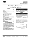
1
FLOOR
Gas-FiredFURNACE
Vented
I
P/N 74521
INSTALLATION
REV. 08/97
OPERATING
INSTRUCTIONS
MODEL
MILLIVOLT
l
NATUNALGAS
AND
NUMBERS
CONTROL
90N30A
SYSTEM
l 90N50A[
1 90N75A
90N65A
exactly, a fire or explosion may result causing property I
I WARNING: If the information in this manual is not followedI
damage, personal injury or loss of life.
I
- Do not store or use gasoline or other flamlnable vapors and
liquids in the vicinity of this or any other appliance.
- WHAT
•
•
•
•
TO DO IF YOU
SMELL
GAS:
Do not try to light any appliance.
Do not touch any electrical switch; do not use any phone
in your building.
hnmediately callyour gas supplier froru a neighbor's phone.
Follow the gas supplier's instructions.
If you cannot reach your gas supplier, call the fire
deparnnent.
- INSTALLATION
AND SERVICE MUST BE PERFORMED
BY A QUALIFIED INSTALLER,
THE GAS SUPPLIER.
WARNING:
Operation
and maintained
The coating selected to provide
longer life to the heat exchanger
may sruoke slightly upon initial
firing. Please provide adequate
ventilation if this occurs.
venting
SERVICE AGENCY
of this furnace
system
and possible
death.
For your
be inspected
at least annually
OR
when not connected
can result
in Carbon
safety, this furnace
by a qualified
to a properly
Monoxide
and the venting
service
(C.O.)
installed
poisoning
system
should
person.
THIS UNIT IS NOT APPROVED
FOR INSTALLATION
IN MOBILE HOMES,
GREENHOUSES,
OR ENVIRONMENTS
INVOLVING DUSTY, WET, CORROSIVE, OR
EXPLOSIVE CONDITIONS.
SUCH CONDITIONS WILL INVALIDATE THE WARRANTY
AND MAY CREATE UNSAFE CONDITIONS.
CONTENTS:
Introduction ...............................................
2
Checking the Gas Piping ...........................
Thermostat Installation .............................
9
10
Lighting ....................................................
To Turn OffGas .......................................
11
11
Adjusting the Pilot Flame ..........................
Orifice Charts ...........................................
12
12
4
5
Adjusting the Main Burner. .......................
Optional Operation ....................................
Maintenance ..............................................
12
13
14
6
6
8
Trouble Shooting .......................................
Repair Parts ...............................................
Warranty. ...................................................
15
16
18
Specifications ............................................
2
Safety Rules ...............................................
2
Helpful Installation Information ................. 3
Installation Requirements ........................... 3
Furnace Location .......................................
4
Fresh Air for Combustion & Venting ..........
Cutting the Floor Opening ..........................
Setting the Floor Furnace ...........................
Installing the Draft Hood ............................
Connecting the Vent ....................................
Gas Supply and Piping ................................
INTRODUCTION
THIS IS A GAS-FIRED, GRAVITY VENTED FLOOR FURNACE THAT WILL OPERATE SAFELY
AND PROVIDE AN EFFICIENT SOURCE OF HEAT WHEN INSTALLED, OPERATED AND
MAINTAINED
AS RECOMMENDED
IN THESE INSTALLATION
AND OPERATING
INSTRUCTIONS.
READ THESE INSTRUCTIONS
THOROUGHLY
BEFORE INSTALLING,
SERVICING, OR USING THE APPLIANCE.
IF YOU DO NOT UNDERSTAND
ANY PART OF
THESE INSTRUCTIONS,
CONSULT
LOCAL AUTHORITIES,
OTHER QUALIFIED
INSTALLERS, SERVICE AGENCIES, THE GAS SUPPLIER OR THE MANUFACTURER.
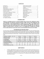
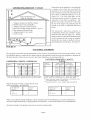
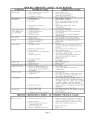
FLOOR FURNACE SPECIFICATIONS
Your floor furnace and drafihood are packed together in one master carton. The carton containing the floor
furnace also contains the thermostat, thermostat wire, insulated staples, furnace key and lighter rod. The drafthood
is packed in its own carton within the master pack and contains screws and rope-like gasket material for attaching
and sealing the draft hood to the floor furnace. Check the model numbers on the two cartons to be sure they
match.
MODEL NUMBER-
NAT. GAS
Hourly BTU Input
Width and Length
Overall Height
Overall Grille Size
Size of Floor Opening
Gas Pipe Size at Furnace
Vent Pipe Size
Floor to Center Line of Vent
90N30A
90N50A
90N65A
90N75A
30,000
14"x32"
29-1/4"
16"x34-1/£ '
14/4
_ " x_2/4
3 _ "
:/2"
4"
22"
50,000
22"x32"
29-1/4"
24"x34"
22/2
_ " x_2/2
3 1 "
:/2"
4"
22"
62,000
24"x38"
29-7/8"
26"x40"
24/2
_ " x_8/2
3 _ "
:/2"
5"
22"
75,000
26"x42"
30-7/8"
28"x44"
26V£'x42V£'
SAFETY
:/2"
5"
22"
RULES
WARNING: IMPROPER INSTALLATION, ADJUSTMENT, ALTERATION, SERVICE OR MAINTENANCE CAN
CAUSE PROPERTY DAMAGE, PERSONAL INJURY OR LOSS OF LIFE. INSTALLATION AND SERVICE _:ST
BE PERFORMED BYA QUALIFIED INSTALLER, SERVICE AGENCY OR THE GAS SUPPLIER. KEEP BURNER
AND CONTROL COMPARTMENT CLEAN. SEE INSTALLATION AND OPERATING INSTRUCTIONS
ACCOMPANYING APPLIANCE. DUE TO HIGH SURFACE TEMPERA]XJRES KEEP CHILDREN, CLOTHING
AND FURNITURE AWAY
Page 2
3.
4.
5.
6.
7.
8.
9.
10.
11.
12.
13.
14.
SAFETY
RULES - Continued
FOLLOW ALL APPLICABLE CODES AND ORDINANCES.
IF THERE ARE NONE, FOLLOW THE
INSTALLATION STANDARDS, LATEST EDITION OF NFPA54/ANSI.Z223.1. A COPY MAY BE OBTAINED
FROM THE AMERICAN GAS ASSOCIATION, 1515 WILSON BLVD., ARLINGTON, VA. 22209, OR THE
NATIONAL FIRE PROTECTION ASSOCIATION, BATTERYMARCH PARK, QuiNcY, MA. 02269.
DO NOT INSTALL THIS FLOOR FURNACE IN A RECREATIONAL VEHICLE, TRAILER OR MOBILE HOME.
DO NOT OPERATE THIS FLOOR FURNACE UNLESS IT IS CONNECTED TO A PROPERLY INSTALLED AND
MAINTAINED VENT SYSTEM. DO NOT EXHAUST FLUE GASES UNDER THE FLOOR FOR ANY REASON.
BE SURE THIS FLOOR FURNACE IS EQUIPPED FOR THE TYPE GAS YOU INTEND TO USE.
LOCATE THE THERMOSTAT IN A ROOM OR SPACE THAT CANNOT BE SEPARATED BY A DOOR OR
OTHER MEANS FROM THE ROOM OR SPACE IN WTIICH THE FLOOR FLIRNACE GRILL IS INSTALLED.
NEVER USE A MATCH, CANDLE, FLAME OR OTHER SOLIRCE OF IGNITION TO CHECK FOR GAS LEAKS.
USE ONLY SOAPY WATEROR LIQUID DETERGENT.
ADEQUATE AIR FOR COMBUSTION AND VENTING MUST BE PROVIDED.
IF IT IS SUSPECTED THAT RISING WATER OR SEEPAGE MAY ENTER THE FLOOR FURNACE, TURN OFF
THE GAS IMMEDIATELY DO NOT USE THIS FLOOR FURNACE IF ANY PART HAS BEEN tENDER WATER.
IMMEDIATELY CALL A QUALIFIED SERVICE TECHNICIAN TO INSPECT THE FLOOR FURNACE AND TO
REPLACE ANY PART OF THE CONTROL SYSTEM AND ANY GAS CONTROL WHICH HAS BEEN UNDER
WATER.
HAVE YOLIR FLOOR FURNACE AND VENT SYSTEM INSPECTED AT LEAST ANNUALLY BY A QUALIFIED
SERVICE TECHNICIAN.
THE GRILL BECOMES HOT WHEN THE FLOOR FLJRNACEIS IN OPERATION. CHILDREN MEYSTBE CLOSELY
SUPERVISED WHEN IN THE PRESENCE OF ANY HEATING APPLIANCE. CONTACT WITH BARE SKIN MAY
RESULT IN SEVERE BURNS. KEEP CHILDREN OFF THE GRILL.
BEFORE CLEANING OR SERVICING THE FLOOR FURNACE, TURN OFF THE GAS AND ALLOW IT TO COOL.
THIS WILL PREVENT BURNS.
ALWAYSLEAVE THE GRILL IN PLACE EXCEPT WHEN CLEANING OR SERVICING THE FLOOR IAIRNACE.
NEVER OPERATE THE FLOOR FURNACE WITHOUT THE SIGHT GLASS ASSEMBLY IN PLACE, OR WITH
THE GLASS BROKEN OR MISSING.
HELPFUL
INSTALLATION
INFORMATION
Do not attempt to heat through more than one doorway in any direction to adjoining rooms.
Always over-estimate the amount of heat required rather than under-estilnate it. Always use the next size floor furnace above
your actual heating requirements.
Seal all cracks around windows, doors, and attic access doors or siNfificant heat loss will occur.
INSTALLATION
REQUIREMENTS
Listed below are steps that are part of a floor furnace installation. You must see that each step is followed closely so that the
floor furnace wilt provide lnaxilnum efficiency with safe operation.
YOU MIYST:
1. Locate the floor furnace in the best available space for safe and efficient operation.
2. Provide fiesh air for combustion and venting.
3. Cut and fiame the floor opening so that the floor furnace fits properly.
4. Attach the draft hood and connect the vent pipe in compliance with applicable codes.
5. Connect an adequate gas supply to the floor furnace.
6. Select the best location for the thermostat.
7. Check and adjust the floor furnace for safe and efficient operation.
If you have any doubts about the correct way to install a floor furnace, contact local authorities or agency, or your gas supplier.
If locat or state codes require that your floor furnace installation be inspected by local authorities, do so after the floor furnace
is installed and before it is put into selMce.
Page 3
FLOOR
FURNACE
LOCATION
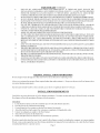
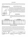
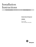
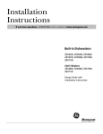
Choose a central location such as a hallway but where occupant traffic is minimal and where there is at least 18 inches of
room from two adjoining sides of the grill to the nearest wall so that occupants may pass without stepping on the gill. See
Figure Number 1.
M
,) WALL
Bedroom
Bath_
<
't
Kitchen
8"Minilntun
Vent Pipe |
Bedroom
Living Room
FIGURE
]
I
1
FIGURE
2
Give consideration to available air for combustion, location in relation to chimney or vent system, thermostat location,
clearance under floor, clearance to combustibles, and heat circulation. Any open foundation is unacceptable as wind can
cause pilot outage and reduced efficiency. Keep furniture, drapes, doors, and other combustible materials at least 12 inches
from the edge of the gill. Never locate the floor furnace closer than 8 inches to a walt and never in a corner. See Figure 2.
Two adjoining sides of the floor furnace must have a minimum clearance of 18". See Figure 1.
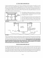
FLOOR
After selecting a location in the home, go beneath the floor and check
the position of the floor furnace in relation to joists, supporting
columns, electric wires, water pipes and walts. There must be a minhnum
of 6 inches clearance between the top of the draft hood and floor
joists. There must also be at least 6 inches clearance between the
bottom of the floor furuace and the ground. See Figure 3.
FLOOR
_ JOIST
FLOOR
FURNACE
Ground
Level
FIGURE
.d_
In order to find the location beneath the floor it may be necessary to
drill a 1/16 inch hole through the floor approximately in the center of
the selected floor furnace location to use as a reference point when
measuring under the floor.
_,
6" Minimum
3
FRESH
AIR FOR
COMBUSTION
AND VENTING
Adequate air for combustion and venting must be provided. Any reduction
can result
in an oxygen
starved
flame
that
emits
Carbon
in the necessary
Monoxide
(C.O.)
amount
an odorless,
of fresh
colorless
air
gas
that can cause serious injury or death.
A ventilated crawl space will usually provide enough tiesh air. However, you
must check to see that there is 1 square inch of free area of ventilation opening for each 1,000 BTU's input of your floor furnace.
EXAMPLE: 50,000 BTU floor furnace
1,000 50 square inches. If another gas burning appliance such as a water heater is
installed within the same crawl space or basement, add the B.T.U.'s of the other appliance to those of the floor furnace before
calculating the total ventilation needed. EXAMPLE: 50,000 B.T.U. floor furnace plus 40,000 B.T.U. water heater equals 90,000
B.T.U. ÷ 1,000 90 square inches. To compensate tbr the loss of square inches of ventilation due to the use of louvers, gills,
or screens add approximately 50% to the square inches calculated. Screen all openings with mesh not less than ¼ inch to
prevent animals or insects from entering the crawl space.
All type "B" vents shall extend in a generally vertical direction with oft;ets not exceeding 45 degees, except that a vent system
having not more than one 60 degee oft;et may be allowed.
Any angle geater than 45 degees t'rom the vertical is considered horizontal. The total horizontal run of a vent plus the
horizontal vent connector shall be not geater than 75 percent of the vertical height of the vent.
Any ofl;ets used should be as far above the drafthood as possible to allow a venting action to begin before any restriction is
encountered.
Page 4
CUTTING
THE FLOOR OPENING
Consult the specification chart on Page 2 t\)r the correct floor opening size for the floor furnace to be installed. Lay out the
opening size on the floor by using masking tape or cutting a piece of cardboard to the opening size. The opening must be cut
square. If you have determined that there is nothing under the floor to interfere with the installation, you are now ready to cut
the opening. Start by drilling 1/_,
inch holes inside the lines of each corner. Use a keyhole saw or a properly grounded saber saw
to cut along the lines making sure to keep the lines straight and the comers square. If the opening dimensions are not correct,
it may be difficult to fit the floor furnace into the opening. Forcing the floor furnace through the opening may create stresses
that cause the floor furnace to be excessively noisy.
Most installation will require cutting a floor joist. Cut the floor joist
so that double headers of the same size lumber can be used to frame
around the floor furnace. Double headers are necessary to maintain
the strength of the floor. See Figure 4.
JOIST
DOUBLE
m
<
< HEADER
FLOOR
FURNACE -'_
If the clearance between the bottom of the floor furnace and the
ground is not adequate, dig a pit that will provide clearances of at
least 6 inches under the floor furnace, 18 inches on the end where
the gas valve is located and 12 inches on the other three sides.
Slope the sides of the pit to prevent dirt fiom caving into the pit. See
Figmre 5.
OPENING
4,
FIGURE
4
FLOOR
FLOOR
i
JOIST
JOIST
FLOOR
"w
6" Minimuln
FURNACE
i
_
_-"_
FIGURE
_-
M2nuln'--t
,,
_
\:e_t pipe £
12"
5
If there is any possibility that water may accumulate in the pit, a drain must be provided. Ifa drain cannot be provided, fabricate
a waterproof pan of at least 16 ounce per square foot sheet copper or a suitable substitute. Size the pan to provide 6 inches
clearance to the bottom of the floor fflmace, 18 inches on the side where the gas valve is located and 6 inches on the other three
sides. The sides of the pan must extend at least 4 inches above the ground. Anchor
the pan to prevent it from floating
up against the bottom of the floor furnace when water is present. Failure to do so may result in the pan
rising to seal offair for combustion and venting. If this occurs, carbon monoxide (C.O.) a colorless,
odorless gas that can cause serious injury or death may be formed.
SETTING
THE
FLOOR
FURNACE
Lay aside the grill and package containing the thermostat, wires, etc., grasp two opposite sides of the outer casing and lower the
floor furnace gently through the opening. Support the furnace evenly by the flange at the top of the outer casing. Trim back
carpet, padding, and other types of floor covering so that the entire flange rests directly on the floor. If not evenly supported
on all four sides, stresses may be created that cause excessive expansion and contraction noises as the floor furnace heats and
cools. Anchor the floor furnace in place by driving two galvanized roofing nails through each side of the outer casing into the
double headers approximately 1 inch below the flange. Place the grill into position making sure it lays flat against the outer
casing flange. Leave the grill in place until time to light the furnace to keep occupants from thlling into the furnace.
Page 5
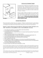
INSTALLING
THE DRAFT HOOD
The draft hood must be installed in the same atmospheric pressure zone as
the combustion air inlet. The draft hood is packed in its o,am carton within
the master pack. Make sure the draft hood received is the correct one for
the floor furnace being installed. Included in the carton are two rope-like
gaskets and 7 sheet metal screws. Begin by pressing the rope-like gasket
material into the groove provided around the two male vent outlets on the
floor furnace. See Figure 6.
GASKET
MATERIAL
Slip the two female couplings in the draft hood over the male outlets
extending through the outer casing, making sure the gaskets remain in
place. Press the draft hood tight against the casing and use the 7 sheet
metal screws to secure it tightly. All 7 screws must be used to prevent
leakage of
without
FIGURE
property
6
Never install or operate a floor furnace
vent gases.
a draft
hood.
To do so could
result
in serious
injury,
damage or death.
CONNECTINGTHEVENT
Refer to the specifications on Page 2 for the correct vent pipe size. Familiarize yourselfwith local codes or contact authorities
to determine the approved material and method of installing the vent. NOTE: An existing vent that has worked for years may
not be adequate for todays design because of higher efficiency requirements that result in lower stack temperatures.
Improper
of life.
or unsafe
Listed
below
venting
are
presents
some
a hazard
guidelines
that may result
to observe
when
in property
installing
damage,
the vent
bodily
injury or loss
system.
1. Never reduce the vent pipe to a size smaller than the outlet on the draft hood.
2. Never run pipe more than 15feet horizontally.
3. The total horizontal mn of a vent plus the horizontal vent connector shall be not greater than 75 percent of the
vertical height of the vent.
4. Slope horizontal pipe upwards at least */4inch per lineal foot.
5. Do not use more than one elbow. An elbow restricts the flow of vent gases by approximately 10%.
6. Use a noncombustible thimble when connecting vent pipe to a masonry chimney.
7. Do not insert vent pipe farther than V4inch into the interior of the chimney.
8. Single wallpipe must not be used.
9. Never connect the vent pipe to aw chimney or vent system serving a solid fuel-burning appliance.
10. If another appliance is being vented through the vent system with the floor furnace, the vent pipe must be
increased to compensate for the additional load.
11. Never install any kind of damper in the vent system.
12. Do not use transite or any other type of ceramic pipe for venting.
Class "B" double wall pipe is acceptable to most codes, and if installed in accordance with the pipe manufacturers instructions
provides the safest and most efficient vent system. Class "B" pipe has an integral lock for securing sections together. These
locks must be properly fitted together. Fasten pipe to draft hood using at least three self-tapping sheet metal screws at equal
intervals around the circumference of the pipe. Support horizontal pipe at three-foot intel-vals with metal strapping attached to
joists.
The floor furnace you have selected was carefully designed to operate both safely and efficiently when vented with the proper
size vent listed t\_r each furnace on Page 2 of these instructions. We do not recommend doing so, but if you must vent into a
masonry chimney use the following instructions.
Continued next page
Page 6
CONNECTING
THE VENT - Continued
I
l
I
l
I
I
l
I
I
m
1/4"
I
I
SAFE
FIGURE
UNSAFE
FIGURE 7B
7A
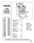
RECOMMENDED
FIGURE 7C
If the floor furnace is vented into a masonry chimney, the chimney must be inspected to deterlnine that it is clear and free of
obstructions and that it is sate for the intended use. The inside of the chimney must be at least 6 inches in diameter or 6 inches
by 6 inches if rectangular. Insert the vent pipe into the chimney through a masonry or noncombustible corrosion-resistant
thimble of the correct diameter. Do not push the pipe fiartherthan ¼ inch into the inside of the chimney. See Figure 7A. Pushing
the pipe farther into the inside of the chimney may cause partial or complete blockage as illustrated in Figure 7B.
Even following these instructions you may still have a venting problem because of the larger area to be heated inside the
chimney. This could cause pilot outage, odors coming tioln the furnace, or noise due to excessive heat not being vented out of
the combustion chamber. If you experience any of these problelns, we recommend running the proper size "B" type vent pipe
down the chimney and connecting to the horizontal mn of vent pipe with a 90-de_ee elbow inside the chimney. See Fig. 7C.
Extend the vent system at least 3 feet above the point where it exits the roof and at least two feet higher than any part of the roof
system within 10 feet. Terlninate with a listed or approved cap. See Figure 9.
MORE THAN
10 FEET
10' OR
LESS
m
<
I
RIDGE
RIDGE
2' Minhnum
CHIMNEY OR
METAL PIPE
3' MINIMUM
FIGURE
9
FIGURE
Page 7
9
CHIMNEY OR
METAL PIPE
3' MINIMUM
CONNECTING
THE VENT
If more than one gas appliance is vented through
a common vent system, the vent should be
increased in size to accommodate the increased
load. Consult your local code or the tables in the
latest edition of NFPA54/ANSI.Z223.1 t\_r the
correct size. If no local codes apply, use the
following alternate method for sizing a vent
connected to more than one appliance.
The
effective area of the vent must be not less than
the area of the largest vent connection plus 50
percent of the areas of additional draft hood
outlets.
- Continued
®
@
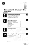
)ical Installation Using
Class "B" Vent Pipe
1. Adequate clearances around floor furnace.
2. Draft Diverter 6" from combustibles.
3.
4.
5.
6.
7.
Adequate clearances around vent pipe.
Horizontal vent pipe sloping upward 1/4" per t\)ot.
Pipe supported with metal straps.
Adequate height of vent system.
Listed vent cap.
The homeowner
appreciates
neatness
in
workmanship and the neat installation usually
functions better than the sloppy one. Double
check your work to verify that all clearances around
the floor furnace and vent system are adequate
and that the vent system is installed to code or
pipe manuthcturers specifications. SeeFigure 10.
@
FIGURE
10
GAS
SUPPLY
AND PIPING
The gas piping system must meet the requirements of local codes or the specifications of the selwicing gas supplier. It must
have adequate capacity to supply the floor furnace and any other appliance within the home with enough gas to maintain the
full rated capacities without excessive pressure drop when all appliances are operating at full rate.
GAS TUBING AND PIPE SIZES - CAPA(ITYGAS PIPE SIZES - CAPACITY-
*NATURAL
GAS
INSIDE PIPE DIAMETER
1/2"
I 3/4"
| 1"
132,000
278,000
520,000
92.000
190,000
350,000
Capacity
73.000
152,000
285,000
B TU
Per Hour
63.000
130,000
245,000
56.000
115,000
215,000
Input
50.000
105,000
195,000
*Based on heating value of 1.000 btu per cubic foot (specific gravity
of 0.6) (a 0.5 PSIG and a pressure drop of 0.3 inch water colunm.
_ength of
_ipe - Feet
0
_.0
_0
_0
_0
_0
*L.E
GAS
Length of
Pipe/Tubing
Feet
10
2O
3O
4O
50
60
**Copper Tubing
**Steel Pipe
Outside Diameter
Inside Diameter
1/2"
3/4"
1/2"
3/4"
275.000
567.000
92,000
329.000
62,000
216,000
189.000
393,000
Capacity
50,000
181,000
152,000
315.000
BTU
41,000
145,000
129,000
267.000
PerHour
37,000
131,000
114,000
237,000
Inpm
35,000
121,000
103,000
217,000
*Undiluted Liquefied Petroleum Gas @ 11 inches water column inlet
pressure. Based on a pressare drop of 05 inches water colunm.
**Copper tubing must comply with limitations of NATIONAL FUEL
GAS (;ODE reference 2.6.3 metallic tubing.
***Steel pipe should be of at least standard weight (Schedule 40).
Support the piping or tubing at re_lar intelwals with
metal pipe strapping. See chart below.
Nominal Steel
Pipe Size
Spacing of
Supports
1/2"
3/4" or 1"
6'
8'
Nominal
size of
tubing O.D.
Spacing of
Supports
1/:2"
4'
58"
or 3/4"
6'
Where local conditions include earthquake, tornado, unstable ground or flood hazards, give special consideration to
increased strength and flexibility of piping supports and connections. Consult local authorities f\3r recommendations.
All unused openings in the piping system must be securely closed gas-tight.
Page 8
CONNECTING
THE GAS PIPING
Refer to Figure 11 for the basic fittings you will need
at the furnace.
1.
2.
GAS VALVE
TEE
3.
4.
5.
6.
7.
FIGURE
9.
10.
Use black iron or steel pipe and fittings or other
pipe and fittings that are approved by local codes.
Use pipe joint compound that is resistant to the
action of Liquefied Petroleum (L.P) Gas or to any
other chemical constituents of the gases to be
conducted through the piping only on male
threads.
Use two wrenches when making the connection
to the valve to keep from bending the mounting
bracket or manifold pipe. Do not overtighten as
damage to the valve can occur.
Provide a 1/8" nominalpipe thread (NPT) plugged
tapping t\_r test gauge connection immediately
upstream of the gas supply connection to the
floor furnace.
Provide a sediment trap at least 6 inches long to
trap dirt and moisture. Provide space to permit
cleaning or emptying.
Use a ground joint union.
Install an approved manual shut-offvalve.
11
ADDITIONAL
L.P. GAS REQUIREMENTS
Have all connections made at the storage tank by a licensed L.R Gas installer.
Have L.R Installer check all lines, piping, and connections fioln the storage tank to the floor furnace when the floor
furnace is connected to the storage tank.
The regulator on the storage tank should be set at 11 inches water column.
CHECKING
THE GAS PIPING
All joints must be tested tbr leaks by applying pressure to the piping system. If the test pressure is equal to or less than L/_,
PSIG the floor furnace must be isolated fioln the gas supply piping system by closing the manual gas shut-offvalve on the
floor furnace. If the test pressure exceeds _/_,
PSIG, the floor furnace and its manual gas shut-offvatve must be disconnected
fiom the gas piping system before testing. Failure
in the gas valve resulting
damage,
bodily injury
in overfiring.
to do so may result in damage
Overfiring
can result
in combustion
to the pressure
chamber
failure,
regulator
property
or death.
Use a mixture of soap and water or liquid detergent to check each joint. Leaks will be indicated by bubbles forming. Correct
even the smallest leak at once. Since some soaps may cause corrosion, or stress cracking, rinse the gas piping exterior with
water after testing to remove the soap.
WARNING
Never
use a match,
test for leaks.
candle,
open flame
To do so may result
or other
in property
method
which
damage,
bodily
could provide
injury
a source
of ignition
to
or death.
(;AUTION: Label all wires prior to disconnection when servicing controls. Wiring errors can cause ilnproper and dangerous
operation. Verify proper operation after servicing.
Page 9
CHECKING
THE GAS PIPING-
CONTINUED
When you have determined that there are no leaks in the gas
piping system you may purge the system of air. Disconnect the
pilot supply tubing from the right side of the valve. See Fimlre
12.
Turn the knob on the gas valve to the pilot position. Press the
knob down and hold until you smell gas at the pilot supply
opening. Release the knob and turn it to the off position.
Reconnect the pilot supply tubing and check t\_rleaks with soap
and water or liquid detergent.
®
Pilot
Adiustlnen
WARNING
When purging gas piping, the area around the floor furnace must
be welt ventilated to allow any gas to dissipate. Liquid Petroleum
(L.R) Gas is heavier than air and may puddle in low places under
the floor. Check thoroughly to determine that no gas is present
bel\_re lighting the floor furnace. Failure to do so could result in
property damage, bodily injury or death.
FIGURE 12
THERMOSTAT
INSTALLATION
Follow the instructions included with the thermostat. Locate the thermostat approximately five feet above the floor. Always
mount the thermostat on an inside wall where it won't be affected by heat or cold sources such as direct sunlight, televisions,
fireplaces, hidden hot or cold water pipe, drafts, etc. The thermostat must never be installed in an adjoining room where a door
can be closed between the thermostat and floor furnace. This floor furnace is equipped with a self-generating control system.
Never connect to a 24-volt transl\_rmer or to the household electric system. Do not use more thermostat wire than is included
with the floor furnace.
Step
Step
Step
Step
WIRE AS INDICATED: (See Figure 13)
1. Connect black limit switch wire to black thermostat wire using wire nut. (Nut not furnished).
2. Connect white thermostat wire to terminal on gas valve marked "TH PP".
3. Connect white limit switch wire to terminal on gas valve marked "TH".
4. Connect the thermostat wires to the thermostat following the instructions provided by the thermostat manufacturer.
LIMIT SWITCH WIRES
THERMOSTAT
WIRE NUT
POWERPILE
GENERATOR
Limit
Switches
|--1
Thermo-
E7--1
v
v
'F_ ,_
o
TERMINAL BLOCK
ON GAS VALVE
er
FIGURE
13
Page 10
nat Bloc
FOR YOUR
SAFETY
READ BEFORE
LIGHTING
WARNING: If you do not follow these instructions exactly, a fire or explosion
result causing property damage, personal injury or loss of life.
\.
This appliance has a pilot which must be lighted by
hand. When lighting the pilot, follow these instructions exactly.
BEFORE LIGHTING smell all around the appliance
area for gas. Be sure to smell next to the floor because
some gas is heavier than air and will settle on the
floor.
department.
C.
D.
WHAT TO DO 1FYOU SMELL GAS:
Do not try to light any appliance.
Do not touch any electric switch; do not use any
phone in your building.
hrnnediately call your gas supplier from a neighbor's
phone. Follow the gas supplier's instructions.
If you cannot reach your gas supplier, call the fire
LIGHTING
Use only your hand to push in or turn the gas control tfllob
Never use tools. If the tfllob will not push in or turn by hand
don't try to repair it, call a qualified service technician. Forc_
or attempted repair may result in a fire or explosion.
Do not use this appliance if any part has been under warm
hmnediately call a qualified service technician to inspect th_
appliance and to replace any part of the control system am
any gas control which has been under water.
INSTRUCTIONS
STOP! Read the information on the safety label.
Set thermostat to lowest setting.
Remove the floor grille.
Place the furnace key on the control rod, push do,a_
slightly and turn clockwise _
to "ALL OFF".
_P,N]_
ALL OFF
5.
6.
7.
8.
OFF" unless the
control rod is
pushed dm_al
slightly.
Wait five (5) minutes to clear out any gas. Then
smell for gas, including near the floor. If you smell
gas, STOP! Follow "B' in the information on the
safety label. If you don't smell gas, go to the next
step.
Remove the sight glass assembly from the opening
on top of the heat exchanger.
Locate the pilot burner looking down through the
sight glass opening.
Turn the control rod counterclockwise
_
until
the pointer is on "PILOT".
I'O TURN
1.
2.
3.
€.
Pilot
Bumer
NOTE: Conn-ol
rod cannot be
turned from
"PILOT" to "ALL
O
OFF
may
Pilot is located
on the side of
and toward
control end
of burner
9. Locate the red piezo igniter button beside the control rod
10. Press down on the control rod with the furnace key
hmnediately begin a series of pushing and releasing th_
red piezo igniter while observing the pilot through the sigh
glass opening, continue to spark until pilot is lit or use th_
lighter md with match. Continue to hold the control roc
down tbr about one (1) minute after the pilot is lit. If it goe_
out, repeat steps 4 through 10.
,,
If control rod does not pop up when released, STOP anc
immediately call your service technician or gas supplier.
•
If the pilot will not stay lit after several tries, turn the contro
rod to "OFF" and call your service technician or ga_
supplier.
11. Replace the sight glass assembly and turn the control roc
countercloclcvvise _
to "BURNER" position. Remow
furnace key and replace the floor grille.
12. Set thermostat to desired temperature.
GAS
TO APPI3ANCI,
Set the thermostat to it's lowest setting.
Allow floor grille to cool, then remove.
Place furnace key on control rod, push slightly and
turn ctoc_vise /"X to "ALL OFF". Do not tbrce.
Replace floor grille.
Page 11
VENT
SYSTEM
After the floor furnace has been burning t\3rfive minutes, hold a match or candle under the draft hood at the air intake area. If
the vent system is working properly, the flame will be pulled into the air inlet of the draft hood. If the vent system is not working
properly, turn the floor furnace off immediately and refer to the installation instructions or local code for proper installation
procedure.
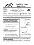
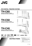
ADJUSTING
THE
PILOT
FLAME
PILOT FLAME ADJUSTMENT
Pilot flame should envelop 3/8 to
1/2 inch of the tip of the generator.
,
_"
4'
3/8 to
€ 1/2"
i l
I
Refer to Figure 17 for the correct size pilot flmne. If adjustment is necessary,
refer to Figure 12 for the location of the pilot adjustment screw. Using a
standard screwdriver, remove the pilot adjustment screw cover. Insert a
small screwdriver into the pilot adjusnnent screw and turn clockwise _ to
decrease the flame or counterclockwise
_
to increase the flame.
If the flame is too low, the safety pilot may cause all of the gas to be cut
off. NOTE: The gas supply to the pilot is unregulated. When line pressure
exceeds 7" Natural Gas, or 11" L.R Gas, a pilot adjustment must be
made.
I
BURNER
This appliance is orificed atthe factory for elevations up to 2,000 feet. If
installed above 2,000 feet, the BTU input must be reduced 4% per 1,000
feet. See the following orifice chart for the proper orifice for a specific
elevation.
FIGURE 17
NATURAL
Vlodel No.
)0N30A
)0N50A
)0N65A
:)RDER
KIT #49800
DRDER
33
KIT #49850
44-i
HIGH
L.P. GAS
GAS
SPE( IFI(_ ELEVATIONS
0 to
2,000 - 4,000 - 6,0002,000' 4.000'
6.000'
8,000'
38
41
42
43
30
31
31
32
26
28
29
30
)0N75A
ORIFICE
ALTITUDE
SPE(IFI(;ELEVATIONS
Model No. 0to
2,000- 4,0006,0002,000' 4,000' 6,000'
8,000'
90P30A
1/16
53
53
54
90P50A
47
49
49
50
90P65A
43
44
45
47
8,000
10,000'
44
35
30
ORDER KIT #49800
90P75A
51
ORDER KIT #49850
KIT
36
37
38
41
2287-2 HIGH ALTITUDE KIT
ADJUSTING
THE
8,000
10,000'
54
51
48
44-1 HIGH ALTITUDE KIT
52
52
53
54
2287-2 HIGH ALTITUDE KIT
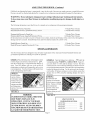
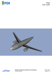
BURNER
After the floor furnace has been burning 15 minutes, remove the bottom pan fiom the outer casing exposing the complete
burner asselnbty. Loosen the screw at the bottom side of the sliding air shutter. Slide the air shutter closed until yellow tips
start to appear at the top of the flame. See Figure 19. (75,000 BTU floor furnace has two burners, both of which may need
adjustment). Now open the shutter slightly beyond the point that the yellow disappears and the flame burns blue. (See
Figure 20). Airborne dust particles may cause flashes or streaks of yellow flame as they are drawn into the flame but will
have no effect on the efficiency of the floor furnace. If you are satisfied that the burner is properly adjusted, tighten the set
screw to lock the shutter in position. Replace the bottom pan. Check air shutter setting at least twice each season to assure
that changing conditions are not causing yellow tipping.
Manifold Tube
Sliding Air Shutter ",,
Set Screw
FIGURE
18
_
4;
IAt
ADJ STM
IMPROPER FLAME ADJUSTMENT
FIGURE
19
Page 12
FIGURE 20
ADJUSTING
THE
BURNER-
Continued
If difficulty in adjusting the burner is experienced, it may be the result of incorrect gas supply pressure or manifold pressure.
Pressure can only be checked and adjusted by a trained selaTice technician using instrmnents desiNled for that purpose.
WARNING: Do not attempt to change pressure settings without proper training and instruments.
To do so may cause your floor furnace to malfunction resulting in property damage, bodily injury, or
death.
The t\_llowing information is provided t\_ruse by a trained selaTicetechnician with measuring instruments.
4.5 Inches Water Column
11.0 Inches Water Column
Minflnum Inlet Pressure,Natural Gas .............................................................
Minhnum Inlet Pressure, Liquefied Petroleum (L.P) Gas ......................................
Maxhnum Inlet Pressurefor Natural Gas .........................................................
7.0 Inches Water Column
Maxhnum Inlet Pressure, Liquefied Petroleum (L.P) Gas .....................................
14.0 Inches Water Column
(If the inlet pressure is found to exceed 14.0 inches water column, check the performance of the control valve thoroughly as
damage may have occurred. If manifold pressure cannot be adjusted, replace the control valve).
3.5 Inches Water Column
10.0 Inches Water Column
Manllbld Pressure,Natural Gas ....................................................................
Manifold Pressure, Liquefied Petroleuln (L.P) Gas ............................................
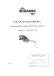
OPTIONAL
OPERATION
Your floor furnace has been designed to meet all safety requirements of the American National Standards Institute and
government re_lations by offering two modes of operation.
OPTION 1. Place the furnace key on the damper control
rod (See Figure 21) and turn counterclockwise
until the warning flag is concealed and the damper is
open. Your floor furnace wilt now cycle on and off
maintaining a moderate grill temperature and an even
room temperature. Your floor furnace wilt function best
on this setting during mild weather.
OPTION 1
In mild weather,
operate furnace
with damper open.
Furnace will cycle
on and offmaintaining a moderate
grill temperature
and an even rooln
temperature.
FIGURE 21
WARNING
FLOOR FURNACE GRILLS BECOME
HOT WHEN FURNACE IS IN
OPERATION. CONTACT OF BARE
SKIN WITH GRILL MAY RESULT IN
SEVERE BURNS. KEEP CHILDREN
OPTION 2. Turn the furnace key cloc_vise
_
until the
warning flag reading "WARNING - GRILL IS HOT Keep off
can cause burns" is visible and the damper is closed. The limit
control will now cease to function and the floor furnace will now
put out the maximum amount of heat until the rooln temperature
reaches the thermostat setting. Use this option only in extremely
cold weather. If furnace continues to cycle on limits, assure that
damper door is 100% closed by adjusting damper door pin if
necessary.
OPTION 2
In extremely cold
weather, close damper
(which exposes warning
plate). Furnace wilt then
put out maximum
amount of heat until
room
temperature
Closed
reaches setting on walt
thermostat.
FIGURE
22
LIMIT SWITCH
TEMPERATURE SETTINGS
90{N,P}30A..........................
90 {N,P}50A..........................
90{N,P}65A..........................
90{N,P}75A..........................
OFF, PROVIDE FENCE OR REGISTER
GUARD FOR THEIR PROTECTION.
Page 13
140o
1600
180o
170o
MAINTENANCE
INSTRUCTIONS
WARNING
Do not use any kind
CAUTION:
Label all wires prior to disconnection when
selaTicing controls. Wiring errors can cause improper and
dangerous operation.
of solvent
fluid to clean your floor furnace.
a residue
or invisible
coating
or cleaning
It may leave
that will burn
or smell when you turn your floor furnace
For proper operation, Floor Furnace must be kept clean. At
regular intervals turn control valve to oft; let cool, relnove reNster
and clean dust and t\)reign material from jacket with vacuum
cleaner.
Use only a damp
Follow a regular sel-vice and maintenance schedule for sate
and efficient operation.
Keep flamlnabte materials away fiom floor thrnace area.
Be sure not to obstruct combustion and ventilation air.
1.
2.
3.
4.
5.
6.
7.
BURNER
Remove bottom pan from outer casing.
Remove 2 screws from burner support bracket.
Remove 2 screws fiom pilot bracket allowing burner to
slide off of manifold and out of floor furnace.
Examine the burner. Ifm_y_distortion is noticed, replace
bumeE
Clean burner ports by inserting a toothpick in ports to
remove any debris that might have accumulated.
Inspect burner for spider webs or dust buildup during the
off-season. If necessary, wash out with garden hose.
Re-install and adjust burner.
SERVI(E
RECORD
SERVI(E
cloth.
Repair service must be performed by qualified
persons. The floor furnace must be inspected
before initial use. An annual cleaning of floor
furnace and safety performance check should be
made by a qualified service person.
More
frequent cleaning may be required when exposed
to the excessive lint conditions due to carpeting
and bedding material, etc. It is imperative that
the control compartment, burners, and circulating
air passageways of the floor furnace be kept clean.
Any safety screen or guard removed for servicing
the floor furnace must be replaced prior to
operating heater.
Have the Floor Furnace checked by a qualified service technician
for venting system, pilot, and burner operation prior to its use
each year.
TO CLEAN
on.
Examine the entire venting system as a routine part of
the safety performance check on an annual basis.
WARNING
RECORD
This is a gas-fired floor furnace. Keep the
area clear of gasoline and other flammable
vapor and liquids. All combustible material
must be kept clear of this area to avoid fire
or explosion.
SERVICE
Page 14
RECORD
SERVICE
RECORD
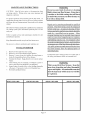
TROUBLE
SYMPTOM
Flame too large
SHOOTING
POSSIBLE
1. Defective operator section of gas valve.
2. Burner orifice too large.
3. If installed
Flame pops back
Noisy Flame
above 2_000 it.
Too much primary air.
1. Too much primary air.
2. Noisy pilot.
3. Burr in orifice (if it whistles
resonates).
Yellow tip flame (some
yellow tipping on L.R
gas is permissible)
Floating flame
Gas odor
Delayed ignition
Failure to ignite
Condensation
Burner won't
Incorrect
of water va
turn off
gas input
Not enough heat
_urner won't turn on
or
BURNER
CORRECTIVE
ACTION
1. Replace complete valve.
2. Check with local gas colnpany for
proper orifice size and replace.
3. Refer to Burner Orifice Sectiom Pg. 12.
Adiust air shutter. See Page 12.
1. Actiust air shutter. See Page 12.
2. Reduce pilot gas with adiusting screw marked
pilot on combination gas control valve. See
Page 12.
3. Remove burr or replace orifice. (Do not
enlarge orifices).
Excessive gas input.
Too little primary air.
Clogged main burner ports.
Clogged draft hood.
Linted up air shutter.
4.
1.
2.
3.
4.
See "Flame Too Large" above.
Actiust air shutter. See page 12.
Clean main burner ports. (Do not enlarge ports).
Clean draft hood.
1.
2.
1.
2.
3.
1.
Blocked venting.
Insufficient primal T air.
Chimney or vent obstruction.
Drafts around appliance.
Gas leak.
Pilot flame too small.
1.
2.
1.
2.
3.
1.
Clean flue passage ways to remove blockage.
Adjust air shutter to increase primal 3' air supply.
Clean chinmey or vent - replace if necessal T.
Eliminate drafts.
Check for dust or lint at air mixer opening
around the shutter.
2.
3.
4.
5. Air shutter open too far.
5.
6.
7.
1.
2.
6.
7. See "Venting".
1. Open all manual gas vanes.
2. Replace gas valve.
Drafts around appliance.
Bad venting.
Main gas off.
Defective gas valve.
_r 1. hnproper venting.
1. Defective or sticking automatic valve.
2. Excessive gas pressure (The supply gas
pressure nmst not exceed 1/2 psi or 14"
water column).
1. Gas input not checked.
2. Clogged orifice.
1. Appliance
undersized
set too low.
3. Incorrect supply pressure.
1. Thermostat set too high.
control
SHOOTING
valve sticks open.
CHART
2. Dirt in pilot orifice.
3. Defective automatic pilot section
combination control valve.
4. Detective
5. Detective
Thermocouple.
combination control
1. See "Venting.
1. Clean or replace valve.
2. To correct this situation
supplying the gas.
in
Page 15
the utility
3. Check supply pressure as outlined above.
1. Lower setting of temp. dial. See "Lighting
Down Instructions".
2. Replace combination
control valve.
PILOT
and Shutting
& VALVE
1. Readjust pilot flame using adjustment screw marked
"Pilot" on combination control valve. See Page 10.
2. Clean pilot orifice with air or solvent, do not ream.
3. Replace entire combination control valve.
4.
valve.
contact
1. Recheck gas input.
2. Check orifice for clogging.
If clogged, clean out the
hole carefully with a smooth wood toothpick.
(Do
not in an?" way enlarge or distort it.
1. This is especially true when a dwelling or room is
enlarged. Have the heat loss calculated and compare to
the appliance output (70% of input). Your gas compan:
or installer can supply you with this information.
If
appliance is undersized, replace with correct size ::::it.
2. Setting of thermostat. See "Lighting and Shutting Down
Instructions".
- AUTOMATIC
1. Pilot flame too large or too small.
and
See Page 1.
Check pilot orifice, close, increase pilot gas flow if
necessal 3" by adiusting at combination control valve.
See Page 12.
(?lean burner ports (Do not enlarge ports).
Check gas supply pressure.
Supply piping is inadequately sized. Consult local
gas utility or competent installer.
Close air shutter to proper setting as outlined in
these instructions (slight yellow tipping is
allowable on L.R gas).
Eliminate drafts.
2. Burner ports clogged near pilot.
3. Low gas pressure.
4. Pilot decreases in size when main burners
come on.
2. Combination
TROUBLE
- MAIN
4.
1.
2.
3.
4.
2. Thermostat
Too much heat
CHART
CAUSES
Replace
thermocouple.
5. Replace valve.
MODELS
IN(LUDED:
90N30A
90N50A
90N65A
90N75A
NAT.
NAT.
NAT.
NAT.
GAS FLOOR FURNACE LIST PRICES
Prices and specifications subject to change
witout notice. All prices
are F.O.B. t:actory. Specifylnodel nulnber
when ordering parts.
®
4
_4_
BURNERASSEMBLY
90N30A
90N50A
FO :
90N65A
BURNERASSEMBLY FOR:
90N75A
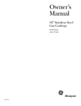
Ml: Contractor, we only sell parts through our wholesalers, but the prices listed are for
your convenience. For prompt parts service, contact the wholesaler from which you
prochased your Cozy heater. NOTE: Parts & schematic drawings on current models are
shown at _v.cozyheaters.com
Page 16
MARCH2005
]
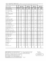
HOW TO PROPERLY ORDER PARTS: In addition to part description and part number, please give model number, serial
number, and type of gas used. This inl\_rlnation can be l\mnd on the rating plate that is attached to heater.
IODEL
NUMBER
NAT.
'ART DESCRIPTION
90N30A
90N50A
90N75A
90N65A
REF.
PART
LIST
PART
LIST
PART
LIST
PART
LIST
NO.
NO.
PRICE
NO.
PRICE
NO.
PRICE
N O.
PRICE
1
23074
5206.20
24099
5291.10
24499
5331.90
24699
NiA
74530
$4.20
74530
$4.20
74532
$5.90
74535
$7.20
2
23001
$167.60
23980
$148.90
24380
$161.00
24580
$202.90
3
23145
$142.30
24175
$180.80
24475
$230.50
24675
$270.20
4
23040
$159.90
24002
$183.00
24402
$210.60
24602
$227.10
10
24048
$14.10
24048
$14.10
24048
$14.10
24048
$14.10
,ighter Rod
11
74510
$2.10
74510
$2.10
74510
$2.10
74510
$2.10
Mve Rod
12
24035
$3.70
24035
$3.70
24035
$3.70
24642
$3.80
gasher. Valve Rod
13
24044
$1.20
24044
$1.20
24044
$1.20
24044
$1.20
2ey, Furnace
14
74205
$1.20
74205
$1.20
74205
$1.20
74205
$1.20
16
91256
$4.50
91256
$4.50
91256
$4.50
91256
$4.50
lear Exchanger
w/Gasket
}asket, Heat Exchanger
,iner, Complete
Assembly
}rille. Floor
;asing, Complete
Assembly
"ision Cap, Complete
astruction
Plate,
Assy.
Lighting
$370.40
;alve Rod Indicator
Plate
17
24045
$1.90
24045
$1.90
24045
$1.90
24045
$1.90
)rafthood Assembly
w/Gasket
18
23200
$74.40
24075
$81.10
24477
$83.80
24676
$88.50
)rafthood Gasket w/Screws
19
23225
$3.70
24077
$4.80
24077
$4.80
24077
$4.80
"hermostat,
22
74592
$20.00
74592
$20.00
74592
$20.00
74592
$20.00
$1.30
Millivolt
_'ire, Thermostat
taples.
23
74518
$1.30
74518
$1.30
74518
$1.30
74518
Wire
24
74209
$1.20
74209
$1.20
74209
$1.20
74209
$1.20
Nat. Gas M.\2
26
74315
$164.30
74315
$164.30
74315
$164.30
74315
$164.30
37
74414
$2.00
74414
$2.00
74414
$2.00
74414
$2.00
NiA
49200
$22.70
49210
$22.70
49220
$22.70
49330
S22.70
20'
Thermostat
Mve, VS821A1061
)isappearing Bushing
,.P. Conversion
1/4x3/8
Kit
,eft Burner w/Pilot Bracket
27
NiA
HA
NiA
NiA
NiA
NiA
74403
$23.80
:ight Burner 75
28
NiA
HA
NiA
N_
NiA
HA
74404
$21.80
_urner w/Pilot Brkt. & Air Adj.
29
74401
$22.30
74401
$22.30
74402
$24.40
ilot Generator,
31
70098
$32.30
70098
$32.30
70098
$32.30
70098
S32.30
Q313A1014
75
M.V.
NiA
NiA
riot Burner w/Orifice
Q350A1271
N.
32
74410
$9.80
74410
$9.80
74410
$9.80
74410
$9.80
riot Burner w/Orifice
Q350A1589
LP
32
74415
$9.80
74415
$9.80
74415
$9.80
74415
$9.80
33
50107
$1.20
50107
$1.20
50107
$1.20
50107
$1.20
ilot Tubing w/Fittings
34
74452
$7.00
74452
$7.00
74452
$7.00
74452
$7.00
_urner Support,
Front
36
24036
$5.10
24036
$5.10
24036
$5.10
24036
$5.10
_nrner Support,
Rear
NiA
24038
$2.60
24038
$2.60
24430
$2.90
24627
$3.40
38
74416
$6.70
74416
$6.70
74416
$6.70
74412
S24.00
39
74390
$3.40
74406
$3.40
74407
$3.40
*74408
$3.40
39
74609
$3.40
74606
$3.40
74607
$3.40
*74608
$3.40
41
24068
$9.80
24068
$9.80
24068
$9.80
24068
$9.80
42
*74306
$9.30
*74307
$9.30
*74308
$9.30
*74309
$9.30
NiA
74320
$8.40
74321
$8.70
74322
$9.50
74323
Sl0.00
iezo Ignitor
43
70050
$5.60
70050
$5.60
70050
$5.60
70050
$5.60
_nitor Wire
44
74351
$5.10
74351
$5.10
74351
$5.10
74351
$5.10
;lectrode
45
74350
$3.70
74350
$3.70
74350
$3.70
74350
$3.70
NiA
24039
$8.20
24039
$8.20
24431
$10.40
24628
$11.70
'Iounting Screws,
Pilot (2)
'Ianil'old
_umer Orifice, Natural
_urner Orifice, LR
Gas
gaming Flag
,imit Control
60Tll
_'iring Harness
_ottom Burner
Cover
Gas
Ml: Contractor, we only sell parts through our
wholesalers, but the prices listed above are l\_ryour
convenience. For prompt parts sera_ice, contact the
wholesaler from which you purchased your Cozy
heater. NOTE: Parts & schematic drawings on
current models are shown at w_v.cozyheaters.com.
P/N 74521
Prices and specifications subject
to change without notice. All
prices are F.O.B. factory.
*2 Required
I
Page 17
MARCH 2005
I
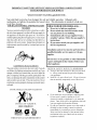
IMPORTANT
SAFETY
BULLETIN
SYSTEM
WHAT
ON YOUR
FOR
GAS
HEATING
YOU DON'T
CONTROL
AND PILOT
EQUIPMENT
KNOW
CAN
HURT
YOU.
Your pilot light system has been designed for safe and reliable operation.
mechanisms
are built-in, the potential for hazard exists. This information
avoid these hazards.
YOUR GAS CONTROL AND PILOT LIGHT
SYSTEM
Your gas control and pilot light system has a safety
device whose purpose is to shut-offthe gas supply to
the appliance if the pilot light goes out. If you have
trouble lighting the pilot or keeping it lit, it may mean
that this safety device is warning you that there is a
problem with your system. Inspection and repairs or
replacement must be made by a trained gas service
technician.
LIGHT
WHAT
Although
safety
is intended to help you
TO DO IF YOU
SMELL
GAS
•
Do not try to light any appliance.
•
Do not touch
any electrical
use any phone
•
Immediately
phone.
If you cannot
gas supplier
Follow
reach
switch;
do not
building.
call your
neighbor's
instructions.
•
in your
...
your
from
a
the gas supplier's
gas supplier,
call
the fire department.
Installation
qualified
and service
installer,
must
service
be performed
agency
by a
or the gas
supplier.
Do not store
vapors
other
TAMPERING
SMELL
or other
in the vicinity
flammable
of this or any
appliance.
IS DANGEROUS
The pilot safety system may also not work if you do
not follow the lighting instructions carefully or if you
tamper with the gas control that you use to light the
pilot. Tampering with the gas control, particularly with
tools, can damage the safety mechanism in the control
and can allow gas to leak. This can result in a fire or
explosion causing property damage, personal injury
or death.
IF YOU
or use gasoline
and liquids
GAS, DON'T
LIGHT
CRITICAL
•
•
SAFETY
POINTS
TO REMEMBER...
Your gas has been odorized so that you can smell
it. Always smell around for gas before lighting
your appliance.
Sniff for L.R-gas at floor level. LP-gas is heavier
than air and may temporarily
exist at floor level.
IT
If you smell gas, do not attempt to light the pilot.
Do not cause a spark by turning on or off
electrical switches or appliances or by using the
IF YOU CAN'T LIGHT
DON'T FIGHT IT!
American Gas
Association
IT,
gama
THIS IS NOT AN ADVERTISEMENT
phone. Turn off the gas to the appliances and call
your gas supplier from another location.
If your gas control has gotten wet as the result of
flooding or other wetting, it must be replaced
immediately by a trained gas service technician.
Water can lead to damage of the internal safety
mechanism in the gas control and can create a
hazardous condition.
LIINIPii' A I AIIIT$
The Louisville
Tin & Stove
original
user
specified
herein, provided
maintained,
the accompanying
serviced,
Co. warrants
product
said product
is installed,
and used according
operated,
to the instructions
and specifications
OUTLINED
IN
WARRANTY
accompanying
the product.
OIR
INSTRUCTIONS,
CONSIDERATIONS
CONTINGENT
ON
INSTALLATION
YOUR
If within
of" one year from
of the product,
manufacturer
proves to be defective
it will replace
been subjected
A
SELFAND _IAY
WARRANTY.
a period
installation
material,
AS
ANY
ARE
BY
Q[ ALIFIED
INSTALLER
(CONTRACTOR).
INSTALLATION
IS NOT RECOM_ IENDED
IN3_ALIDATE
to the
for the period
any part
by
the
due to workmanship
or
such part, provided
to misuse,
the date of
supplied
alteration,
parts
neglect,
have not
or accidents.
The term of the warl"anty for the heat exchanger is covered
in Table A below. Any claim not made within ten (10) days
after the expiration
waived
required
unless,
expense,
period
shall be deemed
The manufacturer
shall have no liability or be
to perform any obligation
under this warranty
when
requested,
the user
the component
or product
the manufacturer
to determine
incurred
of the wan'anty
by the user.
for inspection,
if the claimed
returns,
at the user's
claimed
defective,
to
to enable the manufacturer
defect is covered by this warranty.
No charges for freight, labor or other expenses
in the repair, removal, or replacement
of any product
or component
claimed
manufi_cmrer
to the user, and the manufacturer
to be defective,
liable for any expenses incurred,
any defect in the product.
Service
of the installer.
under
this warranty
the user
of the product
directly
from the installer.
will not be
by the user, in remedying
In the event service
needed,
will be paid by the
is the responsibility
under
this wan'anty
shall request
the appliance) must be completed and returned to the
facto W.
THIS WARRANTY IS EXPRESSLY IN
LIE[? OF ANY OTHER WARRANTIES, EXPRESS
OR IMPLIED (WHETHER WRITTEN OR ORAL).
ANY
IMPLIED
WARRANTY
OF
MERCHANTABILITY
OR OF FITNESS FOR A
PARTICULAR
PURPOSE
IS EXPRESSLY
LIMITED
TO THE DURATION
OF THE
MANUFACTURER'S
EXPRESS,
WRITTEN
WARRANTY.
UNDER NO CIRCUMSTANCES SHALL
THE MANUFACTURER BE LIABLE FOR ANY
SPECIAL, INDIRECT OR CONSEQUENTIAL
DAMAGES OR EXPENSES ARISING DIRECTLY
OR INDIRECTLY FROM ANY COMPONENT OR
FROM THEUSE THEREOF. THE REMEDIES SET
FORTH HEREIN SHALL BE THE EXCLUSIVE
REMEDIES AVAILABLE TO THE USER AND ARE
IN LIEU OF ALL OTHER REMEDIES.
SOME STATES DO NOT ALLOW
LIMITATIONS ON HOW LONG AN IMPLIED
WARRANTY
LASTS,
SO THE
ABOVE
LIMITATIONS MAY NOT APLY TO YOU.
SOME STATES DO NOT ALLOW THE
EXCLUSION OR LIMITATION OF INCIDENTAL
OR CONSEQUENTIAL
DAMAGES,
SO THE
ABOVE LIMITATIONS OR EXCLUSIONS MAY
NOT APPLY TO YOU.
THIS
WARRANTY
GIVES
YOU
SPECIFIC LEGAL RIGHTS, AND YOU MAY
ALSO HAVE OTHER RIGHTS, WHICH VARY,
FROM STATE TO STATE.
is
such service
If the user is unable to locate the
installer, the user should write directly to themanu_acturer,
and the name of an altemative sel_-ice source will be supplied.
The product
safety registration
card (packed inside
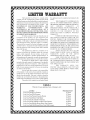
TABLE
A
Warranty for gas appliance heat exchangers only.
Cozy
Cozy
Cozy
Cozy
Cozy
Cozy
Cozy
Cozy
Gas
Gas
Gas
Gas
Gas
Gas
Gas
Gas
Product
Fired Floor Furnace
Fired Wall Furnace
Fired Vented Console Heater
Fired Direct Vent Heater
Fired Counterflow Furnace
Fired Counterflow Direct Vent Furnace
Fired Mobile Home Direct Vent Furnace
Fired Hi-Efficient Direct Vent Walt Furnace
Warranty Period
10 Years
10 Years
10 Years
10 Years
10 Years
10 Years
10 Years
10 Years
I,