1
"
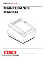
MAINTENANCE
MANUAL
Rev A
Copyright Oki Europe Limited 1999
WARNING: To prevent fire or shock hazard, do not expose this
printer to rain or moisture.
Disclaimer
Information in this publication is subject to change without notice. However, as product
improvements become available, Oki Europe will make every effort to provide updated
information for the products described in this publication.
Oki Europe cannot guarantee that changes in software and equipment made by other
manufacturers, and referred to in this publication, do not affect the applicability of the
information in this publication.
Copyright
© 1999 Oki Europe Limited. All rights reserved.
Revision A, April 1999
No part of this publication may be reproduced, stored in a retrieval system, or transmitted, in any
form or by any means, mechanical, photocopying, recording, or otherwise, without the prior
written permission of Oki Europe Limited.
Trademarks
OKI is a registered trademark of Oki Electric Limited. Epson and ESC/POS are registered
trademarks of Seiko Epson Corporation. Axiohm is a registered trademark of Dardell
Technologies. IBM is a registered trademark of the International Business Machines Corporation.
Federal Communications Commission Radio Frequency Interference
Statement
The OKIPOS 80 Plus III Printer complies with the limits for a Class A computing device in
accordance with the specifications in Part 15 of FCC rules which are designed to minimise radio
frequency interference during installation; however, there is no guarantee that radio or television
interference will not occur in any particular installation. If this equipment does cause interference
to radio or television reception, which can be determined by turning the equipment off and on
while the radio or television is on, the user is encouraged to try to correct the interference by one
or more of the following measures:
i
i
i
Reorient the radio or television receiving antenna;
Relocate the printer with respect to the receiver; and/or
Plug the printer and receiver into different circuits.
If necessary, the user should consult their dealer or an experienced radio/television technician for
additional suggestions. The user may find the following booklet prepared by the Federal
Communications Commission helpful: How to Identify and Resolve Radio/TV Interference
Problems.
This booklet is available from the US Government Printing Office, Washington, DC 20402. Ask
for stock number 004-000-00345-4.
UL, CSA, VDE, CE Statement
Oki Europe POS printers are UL and CSA Listed, VDE Certified, and carry the CE Mark.
Table of Contents
L
7$%/(2)&217(176
352'8&7,1)250$7,21
What is in this book?................................................................................................................1
Who should read this book? .......................................................................................1
What does it cover?.....................................................................................................1
Where can you find more information?......................................................................1
Contacting OKI...........................................................................................................1
Warranty Information...............................................................................................................2
Options ........................................................................................................................2
Service Information ....................................................................................................2
Ordering Supplies ....................................................................................................................3
Paper............................................................................................................................3
Cables..........................................................................................................................3
Description of the OKIPOS 80 Plus III Printer .......................................................................4
OKIPOS 80 Plus III Thermal Receipt Printer............................................................4
Standard Features........................................................................................................5
Optional Features ........................................................................................................5
Technical Specifications ..........................................................................................................6
Printing Specifications................................................................................................6
Print Characteristics....................................................................................................6
Reliability....................................................................................................................8
Dimensions .................................................................................................................8
Weight .........................................................................................................................8
Power Requirements...................................................................................................8
Environmental Conditions..........................................................................................8
Communication Interfaces and Cash Drawer Connectors .....................................................9
Serial Cable.................................................................................................................9
Parallel Cable............................................................................................................11
Cash Drawer Pin Assignments .................................................................................12
&/($1,1*$1'$'-8670(176
Cleaning the Printer ...............................................................................................................13
Cleaning the Thermal Print Head ..........................................................................................13
Making Adjustments ..............................................................................................................13
LL
""
Maintenance Manual
7(67,1*7+(35,17(5
Operating the Keypad ............................................................................................................15
Status LED ................................................................................................................16
Buttons ......................................................................................................................16
Testing the Printer..................................................................................................................17
$66(0%/<',6$66(0%/<
Precautions for Disassembly..................................................................................................21
Necessary Tools ........................................................................................................21
Disconnecting the Power Cord ..............................................................................................22
Disconnecting the Communication Cable................................................................24
Disconnecting the Cash Drawer Cables...................................................................25
Removing the Cover Assembly .............................................................................................26
Removing the Outer Housing ................................................................................................27
Disassemble the Platen ..........................................................................................................29
Disassemble the Cover...........................................................................................................30
Replacing the Print Head .......................................................................................................32
Replacing the Cutter ..............................................................................................................35
Removing the Controller Board Assembly............................................................................36
Replacing the Stepper Motors................................................................................................38
Replacing the Sensors and Keyboard Assembly ...................................................................39
$33(1',;$3$576/,676
Unpacking the Printer ............................................................................................................44
Printer Assembly....................................................................................................................46
Cover and Platen ....................................................................................................................48
Print Head...............................................................................................................................49
Cutter ......................................................................................................................................50
Controller Board.....................................................................................................................51
Motors and Switches..............................................................................................................53
Switch Wiring Detail..............................................................................................................55
$33(1',;%6&+(0$7,&6
Product Information
352'8&7,1)250$7,21
:+$7,6,17+,6%22."
:+2 6+28/' 5($' 7+,6 %22."
This book is intended for trained, service technicians.
:+$7 '2(6 ,7 &29(5"
This book only covers the OKIPOS 80 Plus III Printer, not the entire point-of-sale
system, but it will tell you all you need to know about properly maintaining and servicing
the printer. You will learn how to clean, test, and disassemble the printer.
This book also provides some general and technical information about the printer, so you
will know what the features are, how reliable it is, and what its printing capabilities are.
:+(5( &$1 <28 ),1' 025( ,1)250$7,21"
A Programmer’s Guide is available if you need to know how to program a point-of-sale
terminal or a personal computer to work with the printer. It describes all the commands
the printer recognises to perform its functions.
An Operator’s Guide is also available and is written for new and experienced operators.
It covers setting up and using the OKIPOS 80 Plus III Printer with any point-of-sale
system.
For information about ordering these books, refer to the next section.
&217$&7,1* 2.,
Contact your dealer first for general information about the OKIPOS 80 Plus III Printer
and how it works with your system. If you need more specific information about the
printer, you may contact Oki directly.
The Sales and Technical Support Departments will be able to help you with most of your
questions. Contact the Technical Support Department to receive technical support, order
documentation, receive additional information about the OKIPOS 80 Plus III Printer,
learn more about your warranty, or if you need to send a printer in for service. To order
supplies, or to receive information about other products by Oki, contact the Sales
Department.
You can reach both the Sales and Technical Support Departments of your local office by
accessing the Oki Europe Web site for the most up-to-date contact details.
""
Maintenance Manual
www.okieurope.com
:$55$17<,1)250$7,21
237,216
The OKIPOS 80 Plus III printer does not have any fittable options. The printer is
available in either Serial or Parallel form in light or dark grey cabinets. The printer can be
ordered with or without power supply.
Please contact you dealer or local country Oki Office to enquire about customisation of
the standard product.
6(59,&( ,1)250$7,21
If you need a printer serviced, whether it is under warranty or not, call your dealer. You
may have several options for service depending on your contract. Your dealer may
service the printer directly or have a service agreement with a local service contractor.
If your dealer instructs you to send the printer to Oki for service or if you bought the
printer directly from Oki, contact your local country technical support department, and
ask for a return authorisation. Please have the printer’s model and serial numbers
available. The numbers are on a decal located on the bottom of the printer.
You will need to repack the printer and ship it directly to your Oki dealer or distributer.
Be sure to keep the original packing materials and box. Please refer to “Unpacking the
Printer” in the Operator’s Guide.
Product Information
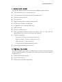
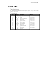
25'(5,1*6833/,(6
You may order supplies by calling your Oki dealer
You may order paper and/or cables.
3$3(5
Paper
Type
Dimensions
Receipt paper
Thermal
80 mm (3.15 inches) wide
100 mm (4.00 inches) diameter
128 mm (420 feet) length
&$%/(6
Cables
110V Power cable
240V Power cable
230V Power cable
Parallel Communication Cable
25-pin male to 25-pin male
Serial communication cable
PC, 9-pin female to 9-pin female
PC, 9-pin female to 25-pin female
""
Maintenance Manual
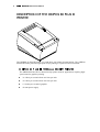
'(6&5,37,212)7+(2.,3263/86,,,
35,17(5
The OKIPOS 80 Plus III Printer is a stand-alone, 40-column, thermal printer. The OKIPOS
80 Plus III Printer performs high-speed receipt printing in a point-of-sale environment.
2.,326 3/86 ,,, 7+(50$/ 5(&(,37 35,17(5
The OKIPOS 80 Plus III is a thermal receipt printer used for applications requiring highspeed extensive graphics printing.
i
i
i
i
31.8 lines per second of text at 6 lines per inch
42.5 lines per second of text at 8 lines per inch
5.3 inches per second of graphics
48 watt power supply
Product Information
67$1'$5' )($785(6
The following features and items are standard on the OKIPOS 80 Plus III Printer:
i
i
i
i
i
i
i
i
i
i
i
44-column printing at 15.6 characters per inch
4.0 inch diameter thermal paper roll 128 m (420 feet) per roll
Automatic cutter (partial cut)
Easy paper load
High resolution graphics capability (8 dots per mm)
RS-232C serial interface with 8K buffer
Configurable receive and image buffer areas
Paper out sensor
Operator controlled self-test
Dual cash drawer connectors (RJ11) and drivers (24V, 1.2 amp pulse for
approximately 150 ms; drawer open/closed status reporting)
Characters and graphics
Print speed - 135 mm (5.3 inches) per second - text
Paper slew speed - 135 mm (5.3 inches) per second
Wide print zone - 72 mm (2.83 inches)
8 dots per mm (203 dpi) horizontal and vertical
i
Reverse video and rotated on the same line
237,21$/ )($785(6
The optional features either replace a standard feature or enhance the operation of the
printer. All optional features are installed at the factory and must be selected when the
printer is ordered.
i
i
i
IEEE 1284 bidirectional parallel
Custom colors and logo
Internal buzzer (for kitchen applications)
""
Maintenance Manual
7(&+1,&$/63(&,),&$7,216
35,17,1* 63(&,),&$7,216
i
i
Printing method: Direct thermal
Print zone: 72 mm (2.83 in.) wide
35,17 &+$5$&7(5,67,&6
The OKIPOS 80 Plus III Printer prints characters in a variety of pitches as shown in the
following table and print samples. All pitches are scaleable up to 64 times as large as the
standard size.
For information about programming the printer to print a particular pitch or style, please
refer to the Programmer’s Guide. You may obtain the guide free of charge in electronic
format from your Oki Dealer.
Pitch (characters per inch)
Maximum Characters per Line
15.6
44
20.3
57
Product Information
""
Maintenance Manual
5(/,$%,/,7<
i
i
i
i
Mean time between failure: 94,000 hours at 12.5% ratio
Mean cycles between failure: 16,000,000 print lines
Mean time to repair: 15 minutes
Cutter: 1,000,000 cut life
',0(16,216
i
i
i
Width: 152 mm (6.0 in.)
Length: 216 mm (8.5 in.)
Height: 142 mm (5.6 in.)
:(,*+7
i
Approximate weight: 4 pounds
32:(5 5(48,5(0(176
The OKIPOS 80 Plus III is designed to be AC powered in domestic and international
markets. The printer is equipped with an external universal input power supply that is
designed to operate world-wide without modification.
Supply
Voltage
Rating (VAC)
Supply
Voltage
Range (VAC)
Frequency
(Hz)
Rated
Power
(watts)
Current Idle
(amps)
Current Printing
(amps)
100 - 240
90 - 264
47 - 63
48
(min.)
0.09 @ 120VAC
0.045 @ 240VAC
0.5 @ 120VAC
0.25 @ 240VAC
(19,5210(17$/ &21',7,216
The printer will run at its best when stored and operated in an environment that meets the
following temperature and humidity conditions:
i
i
i
i
Operating temperature: 0° to 40°C (32° to 104°F)
Storage temperature: -10° to +60°C (-14° to +140°F)
Operating relative humidity: 10% to 90% (non-condensing)
Storage relative humidity: 5% to 90%
Product Information
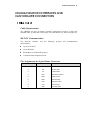
&20081,&$7,21,17(5)$&(6$1'
&$6+'5$:(5&211(&7256
6(5,$/ &$%/(
Cable Requirements
The OKIPOS 80 Plus III Printer standard configuration requires an RS-232C
shielded cable, no more than 50 feet long. The cable must be UL and CSA approved.
RS-232C Communication
The RS-232C interface uses the following protocol and communication
characteristics:
i
i
i
i
Up to 19.2K baud
Up to 8K buffer
Ready/Busy or XON/XOFF protocol
Communications diagnostic mode
Pin Assignments for 9-pin Printer Connector
Pin
Name
Description
1
DCD
Data carrier detect
2
RX
Receive data
3
TX
Transmit data
4
DTR
Data terminal ready
5
GND
Signal ground
6
DSR
Data set ready
7
RTS
Request to send
8
CTS
Clear to send
9
SSD
Secondary data
""
Maintenance Manual
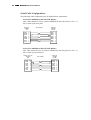
Serial Cable Configurations
The following cable configurations are for different host requirements.
Serial PC to OKIPOS 80 Plus III (Null Modem)
This Cable should be used to connect OKIPOS 80 Plus III printers to PC’s or
PS/2’s with 9-pin serial ports.
Nine-pin
Female
PC
DTR
DSR
DCD
TXD
RXD
GND
RTS
CTS
PN 10-2020
4
6
1
3
2
5
7
8
Nine-pin
Female
Printer
DTR
DSR
DCD
TXD
RXD
GND
RTS
CTS
4
6
1
3
2
5
7
8
Serial AT to OKIPOS 80 Plus III (Null Modem)
This cable should be used to connect OKIPOS 80 Plus III printers to PC’s or
PS/2’s with 25-pin serial ports.
Twenty- f ive-pin
Female
PC
DTR 20
DSR 6
DCD 8
TXD
2
RXD 3
GND 7
4
RTS
5
CTS
PN 10-2021
Nine-pin
Female
Printer
DTR
DSR
DCD
TXD
RXD
GND
RTS
CTS
4
6
1
3
2
5
7
8
Product Information
3$5$//(/ &$%/(
Cable Requirements
The OKIPOS 80 Plus III Printer parallel option requires a 25-pin male D-shell
connector at the printer.
Pin Assignments
Pin(s)
Signal
Description
Direction
1
STROBE
Clock data to printer
Host to Printer
2-9
D0 - D7
Data
Host to Printer
10
ACK\
Printer accepted data
Printer to Host
11
BUSY
Printer busy
Printer to Host
12
PE
Paper out/status
Printer to Host
13
SLCT
Printer selected
Printer to Host
14
AUTOFD
Autofeed paper
Host to Printer
15
ERR\
Printer error
Printer to Host
16
INIT\
Initialize the printer
Host to Printer
17
SLIN
Select printer
Host to Printer
18-25
GND
Ground
""
Maintenance Manual
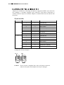
&$6+ '5$:(5 3,1 $66,*10(176
Adapters are available for connecting cash drawers equipped with BNC style connectors
(the standard is a modular, telephone style connector). Cash drawer connections to
emulate Axiohm or Epson are standard. Adapters to emulate Ithaca must be ordered with
the printer.
Epson/Axiohm
Cash Drawer
J7 3-4* Pin #
J7 1-2* Pin #
Epson/Axiohm
1
1
1
Frame Ground
2
2
Drawer Drive - (Ground)
3
3
Status Switch +
4
4
Drawer Drive + (24V Switched)
5
2
Ground
5
No Connect
6
6
Status Switch - (Ground)
1
1
Frame Ground
2
No Connect
2
Ground
3
3
Status Switch +
4
4
Drawer Drive + (24V Switched)
5
5
Drawer Drive - (Ground)
6
6
Status Switch - (Ground)
*This jumper is for compatibility with earlier Epson printers. Pins 3-4 are the default
configuration for these jumpers.
3LQ 'UD Z H U Caution:
3LQ 'UD Z H U Do not connect a telephone line to the cash drawer connector,
otherwise the printer and telephone line may be damaged.
Cleaning and Adjustments
&/($1,1*$1'
$'-8670(176
&/($1,1*7+(35,17(5
Cleaning the printer occasionally and keeping it well maintained will help it to last longer
and run better. Remove paper dust periodically by using a vacuum cleaner or air compressor.
Caution:
Do not use rubbing alcohol or petroleum-based chemicals to clean the
printer as these will damage the plastic parts. Take special care not to
get any cleaner on the electronic components.
None of the internal parts of the printer require lubrication or routine
maintenance. Apply a common cleaner such as fantastik® or Formula
409® to a damp cloth and gently wipe the surface of the printer.
&/($1,1*7+(7+(50$/35,17+($'
Under normal conditions the thermal print head does not need cleaning. However, if the print
characters are not printing correctly, wipe the thermal print head with alcohol and a lint free
cloth.
Caution:
Do not get any alcohol on any of the other parts of the printer
mechanism or cabinetry.
0$.,1*$'-8670(176
The OKIPOS 80 Plus III Printer does not require any adjustments for normal operation.
""
Maintenance Manual
Testing the Printer
7(67,1*7+(35,17(5
The OKIPOS 80 Plus III Thermal Printer has the ability to print self-test printouts on command at
power-up. The self-test prints a variety of information about operating settings and
configurations.
23(5$7,1*7+(.(<3$'
FEED
Paper Feed
Button
LED
Top of Printer
The keypad contains one button and one status LED for easy operation of the printer.
""
Maintenance Manual
67$786 /('
There is a single status LED to display on-line and error conditions. The table below
describes the types of error conditions possible and patterns that the LED will flash under
those conditions.
Error Code Diagnosis Description
The OKIPOS 80 Plus III thermal printer uses a single status LED to display on-line
and error conditions. The table below describes the types of error conditions possible
and the patterns that the LED will flash for those conditions.
Key to Graphical Representation:
• = LED is ON for 0.5 second
•
= LED is ON for 0.1 second
_
= LED is OFF for 0.5 second
_
= LED is OFF for 0.1 second
IN ORDER OR PRECEDENCE
Error Condition Present
Description
Graphical Representation
Verbal
QSM RAM ERROR
______•_•_•_•_•_•_•______
7 quick flashes
RAM ERROR
______•_•______
2 quick flashes
EEPROM VERIFY ERROR
______•_•_•_•_•_•______
6 quick flashes
CHECKSUM VERIFY ERROR ___•••••___
5 quick flashes
THERMAL HEAD OVERHEAT _•_•_•_•_•_•
continuous
rapid,
CUTTER ERROR
______•_•_•______
3 quick flashes
COVER OPEN
_•_•_•_•_•_•_
continuous
PAPER OUT
continuous
______••••••______••••••______ slow,
%877216
The printer includes one button that has the following function.
FEED Button
The FEED button advances receipt paper.
Testing the Printer
7(67,1*7+(35,17(5
You can test the printer to ensure that it is running properly. The sample on the following
page shows what a printout of the test may look like. The test pattern varies depending on the
printer model and the character set selected when the printer was ordered.
Note:
Run the test after loading the paper, but before connecting the printer to
a host system. If the characters do not print properly, check to make
sure the paper is installed correctly.
If the printer is still not working correctly, contact your dealer.
1. Plug the DC power cord from the external power supply into the printer.
2. Plug the AC power cord into the external power supply.
3. Plug the AC power cord into a grounded three-prong power socket.
4. The status LED will start flashing after approximately 1½ seconds.
5. Open the printer cover.
6. Feed a roll of paper into the printer, leave some paper sticking out and close the paper
cover.
7. The printer will print some technical information.
8. To print sample code pages, press the FEED button.
""
Maintenance Manual
OKIPOS 80 PLUS III THERMAL PRINTER
Testing the Printer
These modes are described in the Programmer’s Guide. If you have accidentally entered this
menu mode, turn the printer off and then back on again.
Assembly/Disassembly
$66(0%/<',6$66(0%/<
35(&$87,216)25',6$66(0%/<
Before disassembling any part of the printer, be sure the power is turned off. Disconnect the
external power supply, communication cable, and cash drawer cables.
Caution:
The controller board can easily be damaged by static electricity.
Observe ESD precautions. Wear a grounded wrist strap, and use a
static mat or other protected work surface. Do not place the printed
circuit boards directly on the printer or floor.
1(&(66$5< 722/6
Caution:
Using the wrong tools may cause personal injury or damage the
printer. Be sure to use the proper tools when maintaining or
servicing the printer.
The following list provides the necessary tools to properly maintain the OKIPOS 80 Plus
III Printer.
i
Screwdrivers
#1 Phillips
#2 Phillips
i
Allen hex driver
6.0 inch long shaft
i
Miscellaneous
Small needle-nose pliers
Ohmmeter
Hammer
Small punch
TNM 1321 cutter-lever removing support fixture
""
Maintenance Manual
',6&211(&7,1*7+(32:(5&25'
Caution:
The printer must be grounded through the three-prong power connector.
Do not use a ground-defeating adapter.
1. Unplug the power cord from the grounded three-prong power socket. The printer is off
when the LED is no longer green.
External
Power
Supply
Power
Cord
Assembly/Disassembly
2. Disconnect the power cord from the external power supply.
Back of
Printer
Power Supply
Connector
Power Supply
Cable
External Power Supply
3. Disconnect the external power supply cable from the power supply connector located on
the back of the printer. Pull back on the sleeve that surrounds the connector plug, do not
pull directly on the cord.
""
Maintenance Manual
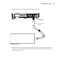
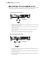
',6&211(&7,1* 7+( &20081,&$7,21 &$%/(
Depending on the interface your system uses, either disconnect the serial or parallel
communication cable from the appropriate connector on the back of the printer.
Disconnect the Serial Cable
Back of
Printer
9-pin Serial
Interface Connector
1. Unplug the AC power cord from the grounded three-prong power socket, and
turn the host system or PC off.
2. Loosen the two mounting screws on each side of the cable connector located on
the back of the printer.
3. Disconnect the 9-pin serial interface cable from the connector located on the
back of the printer.
Refer to page 9 for information on the serial cable requirements.
Disconnect the Parallel Cable
Back of
Printer
25-pin Parallel
Interface Connector
1. Unplug the AC power cord from the grounded three-prong power socket, and
turn off the host system or PC.
2. Loosen the two mounting screws on each side of the cable connector located on
the back of the printer.
3. Disconnect the 25-pin parallel interface cable from the connector located on the
back of the printer.
Assembly/Disassembly
Refer to page 11 for information on the parallel cable requirements.
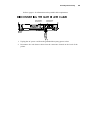
',6&211(&7,1* 7+( &$6+ '5$:(5 &$%/(6
Cash Drawer
Connector 2
Cash Drawer
Connector 1
Back of
Printer
1. Unplug the AC power cord from the grounded three-prong power socket.
2. Disconnect the cash drawer cable from the connectors located on the back of the
printer.
""
Maintenance Manual
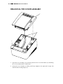
5(029,1*7+(&29(5$66(0%/<
1
3
2
1. Open the cover assembly (1) by pressing down on the cover latch button (2) and lifting
the cover assembly until it is fully open.
2. Grasp the cover assembly (1) firmly and lift up slightly to the right until it snaps free
from the inner housing hinges (3).
Assembly/Disassembly
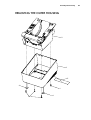
5(029,1*7+(287(5+286,1*
2
3
5
4
1
1
4
""
Maintenance Manual
1. Remove the cover assembly. (See page 26).
2. Turn the printer over.
3. Unscrew the four Phillips screws (1) holding the inner housing (2) to the outer housing
(3).
4. Lift the printer’s inner housing (2) straight out of the outer housing (3).
Note on replacing the outer housing
If you are replacing the outer housing (3), place two new rubber feet bumpers (4) into
the two inserts located on the bottom near the front of the printer. Also, replace the
serial number label (5).
Assembly/Disassembly
',6$66(0%/(7+(3/$7(1
2
3
4
1
1. Remove the cover assembly. (See page 26).
2. Unsnap the platen/gear assembly (1) from the cover assembly (2).
Note: The cutter assembly (3) will hinge forward loosening the cutter spring (4).
Be careful not to lose it.
3. Remove the cutter spring (4).
Note on reassembling the platen
Be sure to place the cutter spring (4) in the slot located in the top of the cutter
assembly (3) and push up. Insert the platen/gear assembly (1), under the cutter
assembly (3), and push up until it can be snapped into the cover assembly (2).
""
Maintenance Manual
',6$66(0%/(7+(&29(5
Assembly/Disassembly
1. Remove the cover assembly. (See page 26).
2. Remove the outer housing. (See page 27).
3. Release the paper feed button (1) from the cover assembly (2) by removing the retaining
ring (3).
Note: Hold the button (1) in place in order to avoid the compression spring (4)
and button from flying out.
4. Remove the compression spring (4) from the cover assembly (2).
5. Unscrew the 4-40 set flat socket screw (5) using a 0.050-inch hex driver.
Notes on installing the cover and adjusting the cover open
switch
1. Use a 0.050-inch hex driver to insert a 4-40 set flat socket screw (5) into the
cover assembly, at its correct location. Refer to the illustration. Before inserting
the set screw, apply Loctite 425 to the set screw threads. Insert the screw until
only two or three threads are visible.
2. Snap the cover assembly into the hinges. Close the cover.
3. The switch is normally wired open in series with the cover lever switch that is
also normally open. Connect an ohmmeter across the black and white wires,
Positions 3 and 4 on the six-pin wire harness connector (J6). The cover lever
switch must be closed in order for the ohmmeter to register the closing of the
cover open switch. As you turn the set screw counterclockwise, the switch will
actuate and the meter reading will switch from open circuit to a very small
resistance. Turn the set screw an additional 1/2 turn (180º).
Note: Before the adjustment, you must remove the shrink tubing from
the cover open switch lever. This will provide access to the hole
in the lever through which the hex driver can get at the set screw.
Replace the shrink tubing after adjusting the set screw.
""
Maintenance Manual
5(3/$&,1*7+(35,17+($'
7
3
3
5
2
Note: Bends
in Ribbon
4
6
1
Assembly/Disassembly
4
1
1
2
3
""
Maintenance Manual
1. Remove the outer housing. (See page 27).
2. Flip the printer upside down and remove the bottom screw (1 on page 32 view).
3. From the front, remove the two screws (2 on page 32 view) and two washers (3 on page
32 view). The ESD shield should easily come off.
4. Remove the ribbon cable assembly (6 on page 32 view).
5. Remove the two head retaining screws (1 on page 33 view).
6. Open the cover, and lower the thermal print head (2 on page 33 view) and paper guide (3
on page 33 view) from the bottom of the printer.
Note on installing the thermal print head
When installing the thermal print head (2 on page 33 view), be sure to properly align
the two print head alignment slots with the holes in the printer before installing the
two head retaining screws (1 on page 33 view).
Assembly/Disassembly
5(3/$&,1*7+(&877(5
13
4
7
9
Pin
3
8
6
10
Slot
1
2
3
12
5
11
1. Remove the outer housing. (See page 27).
2. Slide the cover lever/pin assembly (1) to the left beyond the cutter shaft. Detach the
extension spring (2) from the pin on the inner housing and the pin on the cover lever.
3. Remove the bezel (4) by removing the Phillips screw (3), and slide the bezel to the right
until it is released.
4. Remove the spring pin (5) by carefully tapping it out of the cutter lever (6) and the round
cutter (12) with a hammer and small punch.
5. Slide the cutter lever (6) off the end of the round cutter (12).
6. Remove the three gears [24 tooth gear (7), 36/18 gear (8), and 45/24 tooth gear (9)] from
the outer housing.
7. Unscrew the Phillips flat head screw (10) and the Phillips screw (3), and remove the right
end block (11) from the outer housing.
8. Slide the round cutter (12) to the right until it is free from the inner housing assembly
(13).
Notes on installing the right end block
Attach the right end block (11) with the Phillips flat head screw (10) towards the
front of the printer.
""
Maintenance Manual
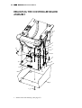
5(029,1*7+(&21752//(5%2$5'
$66(0%/<
8
3
4
12
12
5
2
9
11
6
J5
J6
10
1
J1
J4
J9
13
7
1. Remove the outer housing. (See page 27).
Assembly/Disassembly
2. Disconnect the connectors (1, 2, 3, 4, and 5) from the controller board (6). See the chart
below for connector locations.
3. Turn the printer over. Unscrew the Phillips screw (7) holding the controller board (6) to
the inner housing (8).
4. Remove two screws (11) and two washers (12) from the front of the printer before trying
to separate the controller board (6) from the inner housing (8).
Notes on replacing the controller board assembly
(9-pin communication connector only):
When replacing the controller board (6), remove the board spacer (9) from the old
board and attach it to the new controller board. The spacer is held on the controller
board by one Phillips screw (10).
Connector/Harness
Controller Board Location
Ribbon Cable Assembly
J9
Paper Feed Stepper Motor Cable
J5
Switch and LED Assembly Harness
J6
Switch Wire Harness
J1
Cutter Stepper Motor Cable
J4
""
Maintenance Manual
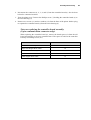
5(3/$&,1*7+(67(33(5027256
4
1
5
3
2
1. Remove the controller board assembly. (See page 36).
2. Remove the paper feed stepper motor (3). Unscrew the Phillips screws (1) holding the
paper feed stepper motor to the outer housing (4).
3. Remove the cutter stepper motor (2). Unscrew the two Phillips screws (5) holding the
cutter stepper motor to the outer housing (4)
Assembly/Disassembly
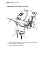
5(3/$&,1*7+(6(16256$1'.(<%2$5'
$66(0%/<
4
5
2
7
1
8
3
6
9
""
Maintenance Manual
1. Remove the controller board assembly. (See page 36).
2. Remove the keypad assembly (4) from the inner housing (5) by pushing the keypad up
though the hole in the inner housing.
3. To remove the cover, open the button subminiature switch (2). Unplug the black single
harness wire and the white wire of the switch wire harness from the tabs on the switch.
Unscrew the screw (1) holding the switch to the inner housing (5).
4. To remove the knife subminiature switch (3), unplug the blue and red wires of the switch
wire harness from the tabs on the switch. Unscrew the screw (6) holding the switch to the
inner housing (5).
5. To remove the cover interlock switch/flat lever assembly (7), unplug the black single
harness wire and the black wire of the switch wire harness from the tabs on the switch.
Unscrew the screw (8) holding the switch to the inner housing (5).
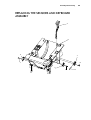
Assembly/Disassembly
2
3
4
1
5
6. To remove the paper exhaust switch/hook lever assembly (4), you must first remove the
paper feed motor (2). To do this, unscrew the Philips screws (1) holding the paper feed
stepper motor to the outer housing (5). Unplug the green and orange wires of the switch
wire harness from the tabs on the switch. Unscrew the screw (3) holding the switch to the
inner housing (5).
""
Maintenance Manual
Note on installation
Knife Home Switch
Cover Interlock
Switch (Lever Flat)
Paper Out Switch
(Lever Hook)
Cover Open Button
Subminiature Switch
Single Harness
(Black)
Switch Wire
Harness (J6)
Pin 1
Refer to the above diagram for the correct switch connectors.
Appendix A: Parts List
$33(1',;$3$576/,676
""
Maintenance Manual
813$&.,1*7+(35,17(5
OKIPOS 80 Plus III
Printer
5
3
2
1
5
6
8
7
9
4
Appendix A: Parts List
ITEM NO.
PART NO.
QTY.
DESCRIPTION
1
98-5800
1
Supply – Series 80PLUS Printer (Spill proof)
1
80-01046
1
Supply – Series 80PLUS Printer (48 watts)
2
06-0561
1
Cord – 110V
2
06-0806
1
Cord – 230V 10A
2
98-1162
1
Cord – 220V Australian
2
98-2173
1
Cord – 230V India/South Africa
2
98-7891
1
Cord – 240V United Kingdom
2
80-01101
1
Cord – 110V
3
80-01047
1
Roll – Small Thermal
4
80-01036
1
Carton – Ithaca
4
80-01055
1
Carton – White
4
80-01251
1
Carton – OKI
5
80-01056
1
Foam set
6
80-01100
1
Insert – Pack set
7
80-01076
1
Form – Series 80PLUS Supplies
8
100-01086
1
Guide – Operator’s
9
91-045
1
Sheet – Warranty
""
Maintenance Manual
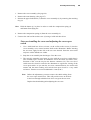
35,17(5$66(0%/<
1
7
3
4
6
5
5
2
Appendix A: Parts List
ITEM NO.
PART NO.
QTY.
1
R80-00035
1
Assembly – Cover (No Platen), Light Gray
1
R80-00056
1
Assembly – Cover (No Platen), Dark Gray
2
R80-00043
4
Screw #6 – 18 x ½ PHPS Tap
1
Assembly – Inner Housing
3
DESCRIPTION
4
R80-00034
1
Housing – Outer, Light Gray
4
R80-00057
1
Housing – Outer, Dark Gray
5
R80-00032
2
Bumper – Rubber Feet
6
R80-00044
1
Label – I.D. and Agency
7
R80-00030
1
Label – Paper Load
""
Maintenance Manual
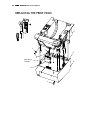
&29(5$1'3/$7(1
4
5
7
3
6
2
1
ITEM NO.
PART NO.
QTY.
DESCRIPTION
1
R80-00045
1
Assembly – Platen and Gear
2
R80-00005
1
Spring – Cutter
3
520-9800006
1
Ring – Retaining
4
R80-00046
1
Button – Paper Feed, Dark Gray
4
R80-00058
1
Button – Paper Feed, Light Gray
5
R80-00002
1
Spring – Compression
6
R80-00004
1
Screw – #4 - 40 x 3/8 Socket
7
R80-00066
1
Assembly – Cover (No Platen), Light Gray
7
R80-00056
1
Assembly – Cover (No Platen), Dark Gray
Appendix A: Parts List
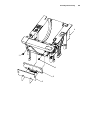
35,17+($'
1
4
1
3
1
2
2
3
ITEM NO.
PART NO.
QTY.
1
R80-00026
2
Screw – M3 x 6 mm PHPS SEMS
2
R80-00008
1
Print head – Thermal
3
R80-00047
1
Guide – Paper
1
Assembly – Inner Housing
4
DESCRIPTION
""
Maintenance Manual
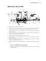
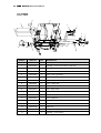
&877(5
13
14
4
9
7
11
3
8
3
5
ITEM NO.
PART NO.
QTY.
1
R80-00027
1
Assembly – Cover Lever and Pin, Dark Gray
1
R80-00059
1
Assembly – Cover Lever and Pin, Light Gray
2
R80-00024
1
Spring – Extension
3
R80-00033
2
Screw #6 - 18 x 3/8 PHPS Tap
4
R80-00028
1
Bezel – Front, Light Gray*
4
R80-00060
1
Bezel – Front, Dark Gray*
5
R80-00010
1
Pin – Spring 0.094 x 0.50 lg
6
R80-00067
1
Lever – Cutter 40q
7
R80-00016
1
Gear – 24 Tooth with Pin
8
R80-00015
1
Gear – 36/18 Tooth
9
R80-00014
1
Gear – 45/24 Tooth
10
R80-00000
1
Screw – #6 - 18 x 3/8 PHPS Tap
11
R80-00019
1
Block – Right End
12
R80-00048
1
Cutter – Round
13
80-01021
1
Label, Ithaca
13
R80-01078
1
Label, UTC
13
80-01252
1
Label, OKI Europe
1
Assembly – Inner Housing
14
10
12
2
1
* Order Item 13 when ordering Item 4.
DESCRIPTION
6
Appendix A: Parts List
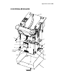
&21752//(5%2$5'
8
3
3
5
2
6
7
J5
J6
1
Note: Bends
in ribbon
J9
J1
J4
4
1
""
Maintenance Manual
ITEM NO.
PART NO.
QTY.
1
R80-00033
2
Screw – #6 - 18 x 3/8 PHPS Tap
2
R80-00049
2
Screw – #4 - 40 x 1/8 PHP
3
R80-00050
2
Washer – #4 External Tooth
4
R80-00051
1
Shield – Ground
5
R80-00013
1
Spacer – P.C. Board (Serial)
6
R80-00065
1
Controller Board – Serial
6
R80-00064
1
Controller Board – Parallel
6
R80-00061
1
Controller Board – Serial with Audible Buzzer
6
R80-00062
1
Controller Board – Parallel with Audible Buzzer
7
R80-00068
1
Assembly – Ribbon Cable
1
Assembly – Inner Housing
8
Connector/Harness
DESCRIPTION
Controller Board Location
Ribbon Cable Assembly
J9
Paper Feed Stepper Motor Cable
J5
Switch and LED Assembly Harness
J6
Switch Wire Harness
J1
Cutter Stepper Motor Cable
J4
Appendix A: Parts List
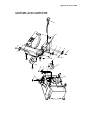
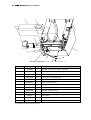
027256$1'6:,7&+(6
8
10
3
4
3
5
3
4
9
1
6
2
3
1
7
10
""
Maintenance Manual
ITEM NO.
PART NO.
QTY.
1
R80-00026
4
Screw – M3 x 0.5 x 6 mm PHPS SEM
2
R80-00020
1
Motor – Stepper 7.5” (Cutter)
3
R80-00022
4
Screw – #2 - 28 x 7/16 PHPS Tap
4
R80-00025
2
Switch – Subminiature
5
R80-00018
1
Assembly – Switch and Flat Lever
6
R80-00052
1
Motor – Stepper 7.5” (Paper feed)
7
R80-00009
1
Assembly – Switch and Hook Lever
8
R80-00021
1
Assembly – Paper Feed Switch/LED
9
R80-00053
1
Tubing – Heat Shrink 0.80 Lg
1
Assembly – Inner Housing
10
DESCRIPTION
Appendix A: Parts List
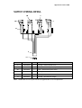
6:,7&+:,5,1*'(7$,/
3B
2
3A
7
10
9
Pin 1
ITEM NO.
PART NO.
QTY.
DESCRIPTION
2
R80-00018
1
Assembly – Switch and Flat Lever
3A
R80-00025
1
Switch – Subminiature (Cover Open Bottom)
3B
R80-00025
1
Switch – Subminiature (Knife Home)
7
R80-00009
1
Assembly – Switch/Lever Hook
9
R80-00023
1
Assembly – Wire Harness
10
R80-00007
1
Assembly – Wire Harness (Single)
Note: Shrink tube on cover open switch to be applied after set screw adjustment.
""
Maintenance Manual
9
4
3
1
2
8
5
6
6
7
Note End Orientation
5
ITEM NO.
PART NO.
QTY.
1
R80-00027
1
Assembly – Cover Lever and Pin, Dark Gray
1
R80-00059
1
Assembly – Cover Lever and Pin, Light Gray
2
R80-00024
1
Spring – Extension
3
R80-00033
1
Screw – #6 - 18 x 3/8 PHPS Tap
4
R80-00028
1
Bezel – Front, Light Gray*
4
R80-00060
1
Bezel – Front, Dark Gray*
5
R80-00049
2
Screw – #4 - 40 x 1/8 PHPS
6
R80-00050
2
Washer – #4 External Tooth
7
R80-00054
1
Assembly – Braided Cable
1
Assembly – Inner Housing
8
DESCRIPTION
9
80-01021
1
Label, Ithaca
9
R80-01078
1
Label, UTC
9
80-01252
1
Label, OKI Europe
* Order Item 9 when ordering Item 4.
Appendix A: Parts List
Adjust set screw on cover assembly, cover assembled to inner housing, apply tubing
and heat shrink as shown.
1
Cover Assembly
(Complete)
Inner Housing Assembly (Complete)
2
0.39”
ITEM NO.
PART NO.
QTY.
DESCRIPTION
1
Assembly – Cover (Complete)
1
Assembly – Inner Housing (Complete)
1
R80-00055
1
Screw – #4 - 40 Set
2
R80-00053
1
Tubing – Heat Shrink 0.80 Lg
Appendix B: Schematics
$33(1',;%
6&+(0$7,&6
""
Maintenance Manual