1
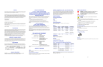
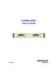
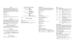
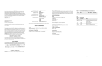
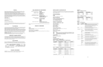
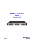
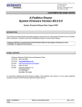
Application of Council Directive(s): Manufacturer’s Name: Manufacturer’s Address: European Representative Name: European Representative Address: Conformance to Directive(s)/ Product Standards: Enterasys Networks, Inc. is a subsidiary of Cabletron Systems, Inc. 2001 by Enterasys Networks, Inc. All Rights Reserved Equipment Type/Environment: Printed in the United States of America Order Number: 9033687-01 June 2001 SPECIFICATIONS SSR-ATM29-02 89/336/EEC 73/23/EEC Enterasys Networks, Inc. 35 Industrial Way PO Box 5005 Rochester, NH 03867 Mr. Jim Sims Enterasys Networks Ltd. Nexus House, Newbury Business Park London Road, Newbury Berkshire RG14 2PZ, England The SSR-ATM29-02 is a modular, high-performance OC-3c ATM interface for the X-Pedition 8000 and 8600. The module is optimized to provide an ATM uplink to an ATM backbone, and supports two modular slots, each of which accepts T1/E1, T3/E3 and OC-3c (single mode and multimode fiber, as well as unshielded twisted pair) interface. The fully integrated design of the X-Pedition family increases the value of the product line by providing a seamless solution to support the industry’s most complete range of technology and media options. This scalable framework ensures full cross-platform compatibility and allows for the smoothest possible migration as customers’ technology and interface requirements evolve. EC Directive 89/336/EEC EC Directive 73/23/EEC EN 55022 EN 55024 EN 60950 EN 60825 Networking Equipment, for use in a Commercial or Light Industrial Environment. Interface DECLARATION OF CONFORMITY NOTICE Enterasys Networks and its licensors reserve the right to make changes in specifications and other information contained in this document without prior notice. The reader should in all cases consult Enterasys Networks to determine whether any such changes have been made. The hardware, firmware, or software described in this manual is subject to change without notice. IN NO EVENT SHALL ENTERASYS NETWORKS AND ITS LICENSORS BE LIABLE FOR ANY INCIDENTAL, INDIRECT, SPECIAL, OR CONSEQUENTIAL DAMAGES WHATSOEVER (INCLUDING BUT NOT LIMITED TO LOST PROFITS) ARISING OUT OF OR RELATED TO THIS MANUAL OR THE INFORMATION CONTAINED IN IT, EVEN IF ENTERASYS NETWORKS AND ITS LICENSORS HAVE BEEN ADVISED OF, KNOWN, OR SHOULD HAVE KNOWN, THE POSSIBILITY OF SUCH DAMAGES. Enterasys Networks, Inc. 35 Industrial Way Rochester, NH 03866-5005 Enterasys Networks, Inc. declares that the equipment packaged with this notice conforms to the above directives. X-Pedition and Enterasys are registered trademarks of Enterasys Networks or its licensors. All other product names mentioned in this manual may be trademarks or registered trademarks of their respective companies. Ports Depending on the APHY used, 1 or 2. XP 8000/8600 2-port base module Physical Dimensions Size: 27.94 cm H x 19.68 W x 3.94 D (11.00 in. H x 7.75 W x 1.55 D) Weight: 1.4 kg (3.0 lb.) Power Consumption 30-35 Watts (depending on which APHY is installed) AGENCY STANDARDS Temperature FCC NOTICE This device complies with Part 15 of the FCC rules. Operation is subject to the following two conditions: (1) this device may not cause harmful interference, and (2) this device must accept any interference received, including interference that may cause undesired operation. NOTE: This equipment has been tested and found to comply with the limits for a class A digital device, pursuant to Part 15 of the FCC rules. These limits are designed to provide reasonable protection against harmful interference when the equipment is operated in a commercial environment. This equipment uses, generates, and can radiate radio frequency energy and if not installed in accordance with the operator’s manual, may cause harmful interference to radio communications. Operation of this equipment in a residential area is likely to cause interference in which case the user will be required to correct the interference at his own expense. WARNING: Changes or modifications made to this device which are not expressly approved by the party responsible for compliance could void the user’s authority to operate the equipment. INDUSTRY CANADA NOTICE This digital apparatus does not exceed the class A limits for radio noise emissions from digital apparatus set out in the Radio Interference Regulations of the Canadian Department of Communications. Le présent appareil numérique n’émet pas de bruits radioélectriques dépassant les limites applicables aux appareils numériques de la class A prescrites dans le Règlement sur le brouillage radioélectrique édicté par le ministère des Communications du Canada. VCCI NOTICE This is a class A product based on the standard of the Voluntary Control Council for Interference by Information Technology Equipment (VCCI). If this equipment is used in a domestic environment, radio disturbance may arise. When such trouble occurs, the user may be required to take corrective actions. Safety Meets the requirements of UL 1950, CSA C22. No. 950, EN 60950, IEC 950, 73/23/EEC, and EN 60825. Electromagnetic Compatibility Compliant with the requirements of FCC Part 15, CSA C108.8, EN 55022, EN 61000-3-2, EN 61000-3-3, VCCI V-3, EN 55024, 89/336/EEC, and AS/NZS 3548 Protocols RFC 2225 Classical IP over ATM (CLIP) RFCs/MIBs RFC 1483, Multiprotocol Encapsulation over ATM Adaptation Layer 5; RFC 1595, SONET MIB; RFC 1695, ATM MIB; RFC 2495, DS1 MIB; RFC 2496, DS3 MIB; RFC 2225, Classical IP over ATM Humidity LEDs Condition Status Hotswap LEDs (2) Yellow (Top) Unit is not functioning, cannot hotswap. Green (Bottom) Unit is operational. Port 1 Traffic LEDs (2) Tx Green (Top) Indicates when the transceiver receives packets. Rx Green (Bottom) Indicates when the transceiver receives flowcontrol packets. Tx Green (Top) Indicates when the transceiver transmits packets. Rx Green (Bottom) Indicates when the transceiver transmits flowcontrol packets. Green The PHY is operating properly and a link is established. Yellow The PHY is inactive due to media errors. Blinking Green The PHY was disabled by management. Off No connection. Yellow CLASS A ITE NOTICE The diagnostics have detected a fault. WARNING: This is a class A product. In a domestic environment this product may cause radio interference in which case the user may be required to take adequate measures. Lightning (Bottom) XP-APHY-21 XP-APHY-29IR XP-APHY-22 XP-APHY-82 WARNING: The APHY-21, APHY-29, and APHY-29LR use Class 1 Lasers. Do not use optical instruments to view laser output. The use of optical instruments to view laser output increases eye hazard. LED Indicators LED PHY (Top) This module operates with the following APHYs (you may purchase them separately from the module) connected to the outside world. For information about these APHYs, consult the Enterasys Networks web site. ELECTRICAL HAZARD: The APHY-82 and APHY-92 are designed for intra-building use only. A properly approved CSU must be used for attachment to outside telecommunications lines (T1/E1). 5% to 90% (non-condensing) Port 2 Traffic LEDs (2) Options Available XP-APHY-67 XP-APHY-77 XP-APHY-92 Operating: 41° to 104°F (5° to 40°C) Storage: -22° to 164°F (-30° to 73°C) Table 1 The combination of the X-Pedition and the SSR-ATM29-02 OC-3c module provide a complete solution for both the service provider and enterprise markets. Interconnecting IP networks over an ATM backbone is done by many service provider and enterprise customers. The OC-3c module provides the vital link between the network’s switch-router solutions and the ATM-based solution in the WAN. Each PVC on the module can be configured as a routed IP interface, and the ATM backbone can provide connectivity from one routed backbone to another. Blinking Green The PHY port has been redirected elsewhere. Off Unit is operating properly. 1 2 INSTALLING THE MODULE ELECTRICAL HAZARD: Only qualified personnel should perform installation procedures. Handling the Module CAUTION: The SSR-ATM29-02 module is easily damaged by electrostatic discharge. To prevent electrostatic damage, observe the following guidelines: • Do not remove the module from its packaging until you are ready to install it. • • • Do not touch any of the module’s pins, connectors or components. • Store or transport this module only in appropriate anti-static packaging. Hold the module only by its edges or front panel. Wear an anti-static wristband connected to a suitable earth ground whenever handling the module. Equipment Checklist After unpacking the SSR-ATM29-02, check the contents of the box to be sure you received the following items: • • TROUBLESHOOTING Connector Pin Assignments The connector pins are assigned as follows: Table 2 APHY-82 and APHY-92 Pin Assignments Proper Boot sequence • The control module on the chassis should indicate that the board was detected and is operating correctly. Pin Connection 1 Receive analog signal 2 Receive reference 3 Pin used for shield reference if you use a shielded cable 4 Transmit analog positive pulse 5 Transmit analog negative pulse 6 Pin used for shield reference if you use a shielded cable Common Errors • Make sure the chassis is connected to a terminal through a console port. Hotswap You may install this module into a live system without powering off the device. An active module can be removed from a live system only under the following conditions: • Press the hotswap button. The green LED should turn off and the yellow LED should turn on. When the yellow LED is on, you can safely hotswap the module. One SSR-ATM29-02 module in static bag One disposable anti-static wristband Instructions CAUTION: Before performing any upgrade or installation, ensure that you are properly “grounded” to avoid electrostatic discharge. However, since you can hotswap the SSR-ATM29-02, the XP 8000/ 8600 may continue running. Tools This installation requires the following tools: Anti-static wristband Phillips screwdriver 1. Remove the coverplate. If a coverplate is installed over the expansion slot, remove the coverplate. 2. Slide the SSR-ATM29-02 into the expansion slot. Slide the module all the way into the slot, firmly but gently pressing to ensure that the pins on the back of the module are completely seated in the backplane. NOTE: Make sure the circuit card (and not the metal plate) is between the card guides. Check both the upper and lower tracks. Preliminary Setup Figure 1 Insert card between card guides Firmware Image Requirements Version 3.0.0.0 or later. Card Guides Circuit Card CLI Setup Enter the following commands at the CLI before implementing any configurations. 1. Enable —> Configuration —> <Enter>. 2. Once you reach the configuration prompt, you can create the ATM interface using CLI commands as described in the ATM section of the X-Pedition CLI manual. Enter the ? character to view the options available to you in configuration mode. 3 P2 SSR-ATM29-02 ATM MODULE Offline ADDITIONAL INFORMATION For additional information about installing this module or to learn more about what capabilities are included in the firmware release you are using, visit the Enterasys Networks web site. Getting Help For additional support related to the Common CLI syntax or this document, contact Enterasys Networks using one of the following methods: World Wide Web http://www.enterasys.com/ Phone (603) 332-9400 Internet mail [email protected] FTP Login Password ftp://ftp.enterasys.com anonymous your email address To acquire the latest image http://www.enterasys.com/download for this product and any available release notes Additional documentation Online P1 Before contacting Enterasys Networks for technical support, have the following information ready: • Your Enterasys Networks service contract number • • A description of the failure • The serial and revision numbers of all involved Enterasys Networks products in the network • • A description of your network environment (layout, cable type, etc.) Swap SSR-8 3. Tighten captive screws. Align the captive screws with the holes in the face of the module and tighten the screws to secure the SSR-ATM29-02 to the chassis. 4 http://www.enterasys.com/support/manuals To send comments or suggestions concerning this document, contact the Technical Writing Department via the following email address: [email protected] Please include the document Part Number in the email message. Hot Metal Plate SSR-ATM29-02 A description of any action(s) taken to resolve the problem (e.g., changing mode switches, rebooting the unit) Network load and frame size at the time of trouble (if known) 5 Quick Start Web Site: http://www.enterasys.com/ 9033687-01