1
917o258473
NUMB
OWNER'S
MANUAL
• Assembly
o Operation
®Customer Responsibilities
®Service and Adjustments
, Repair Parts
CAUTION:
Read and follow
all safety rules and instructions
before operating
this equipment,
FOR CONSUMER ASSISTANCE HOT LINE, CALL THIS TOLL FREE NUMBER: 1-800-659-5917
HHIIIIII
IIIIIIIIIIII III II IIIIIIIIIIIIIIIIIIIIIIIIIIIIIIIIIII
III
I
IIIIIIIIII
SAFETY
RULES
Practices
for Ride-On
Safe Operation
Mowers
A
IMPORTANT:
THIS CUTTING MACHINE IS CAPABLE OF AMPUTATli"_G HANDS AND FEET AND THROWING OBJECTS..
FAILURE TO OBSERVE THE FOLLOWING SAFETY INSTRUCTIONS
COULD RESULT IN SERIOUS INJURY OR DEATH.
I.
*
.
.
,
.
.
*
•
•
•
•
•
.
.
GENERAL OPERATION
Read, understand, and follow all instructions in the manual
and on the machine before stading_
Only allow responsible adults, who are familiar with the
instructions, to operate the machine.
Clear the area of objects such as rocks, toys, wire, etc.,
which could be picked up and thrown by the blade.
Be sure the area is clear of other peoplebefere mowing. Stop
machine if anyone enters the area.
Never carp/passengers.
Do not mow in reverse unless absolutely necessary. Always
look down and behind before and while backing.
Be aware of the mower discharge direction and do not point
it at anyone. Do not operate the mower without either the
entire grass catcher or the guard in place,
Slow down before tumingo
Never leave a running machine unattended. Always turn off
blades, set parking brake, stop engine, and remove keys
before dismounting.
Turn off blades when not mowing_
Stop engine before removing grass catcher or unclogging
chute.
Mow only tn daylight or good adificiaI light
Do not operate the machine while under the influence of
alcohol or drugs_
Watch for traffic when operating near or crossing roadways
Use extra care when loading or unloading the machine into
a trailer or truck..
lU. CHILDREN
Tragic accidents can occur if the operator is not alert to the
presence of children.
Children are often attracted to the
machine and the mowing activity..
Never' assume that
children will remain where you last saw them,
•
Keep children out of the mowing area and under the watchful
care of another responsible adult,
•
Be alert and turn machine off if children enter the area_
•
Before and when backing, look behind and down for small
children.
,
Never carry children. They may fall off and be seriously
iniured or interfere with safe machine operation..
Never allow children to operate the machine
Use extra care when approaching blind corners, shrubs,
trees, or other objects that may obscure vision.
•
•
IV. SERVICE
°
Use extra care in handlinggasoline and ether'fuels. They ere
flammable and vapors are explosive_
Use only an approved container.
Never remove gas cap or add luel with the engine
running, Allow engine to cool before refuefing. Do not
smoke
Never refuel the machine indoors..
Never store the machine or fuel container inside where
there is an open flame, such as a water heater.
Never run a machine inside a closed area.
Keep nuts and bolts, especially blade attachment bolts, tight
and keep equipment in good condition°
Never tamper with safety devices. Check their proper
operation regularly.
Keep machine free of grass, leaves, or other debris build-up.
Clean oil or fuel spillage.. Atlow machine to cool before
stodng.
Stop and inspect the equipment it you strike an object.
Repair, if necessary, before restarting.
Never make adjustments or repairs with the engine running
Grass catcher components aresubject towear, damage and
deterioration, which could expose moving parts or altow
objects to be thrown. Frequently check components and
replace with manufacturer s recommended parts, when necessary_
Mower blades are sharp and can cut Wrap the blade(s) or
wear gloves, and use extra caution when servicing them
Check brake operation frequently. Adjust and service as
required,
,,
•
I1o SLOPE OPERATION
Slopes are a major factor related to !oss-of-controi
and
tipover accidents, which can result in severe injury or death.
All slopes require extra caution, if you cannot back up the
slope or if you feel uneasy on it, do not mow it.
DO:
•
Mow up and down slopes, not across.
•
Remove obstacles such as rocks, tree limbs, etc.
•
Watch for holes, rats, or bumps. Uneven terrain could
overturn the machine_ Tall grass can hide obstacles.
•
Use slow speed. Choose a low gear so that you will not have
to stop or shift while on the slope_
•
Follow the manufacturer's
recommendations for wheel
weights or counterweights to improve stability.
•
Use extra care with grass catchers or other attachments
These can change the stability of the machine.
•
Keep a!l movement on the slopes slow and gradual Do not
make sudden changes in speed or direction_
•
Avoid starting or stopping on a slope, If tires lose traction,
disengage the blades and proceed slowly straight down the
slope,,
DO NOT:
•
Do not turn on slopes untessnecessary, and then, turnslowly
and gradually downhill, if pessible_
•
Do not mow near drop-offs, ditches, or embankments. The
mower could suddenly turn over if a wheel is over the edge
of a cliff or ditch, or if an edge caves in..
•
Do not mow on wet grass. Reduced traction could cause
sliding..
•
Do not try to stabilize the machine by putting your foot on the
ground.,
•
Do not use grass catcher on steep slopes.
,,
•
,,
•
•
,,
•
•
•
I .... A
portant safety precautions.
It means
CAUTION!!! BECOME ALERT.t!! YOUR
Look for this symbol to point out' imSAFETY IS INVOLVEDt
J
CAUTION: Always disconnect spark plug
spark
plug
in orderwhere
to prevent
accidental
wire and
placewlre
it cannot
contact
starting when setting up, transporting,
adjusting or' making repairs,
iii iiiii
iil&lllll
WARNING'IIIIII'IIII'IIIIIIIIIIH"
i
_
iii
The engine exhaust from this product conins cnemicals Known to the State of California to cause cancer, birth defects, or other
reproductive harm.
H=II
i
'tJllll
PRODUCT SPECIFICATIONS
CONGRATULATIONS
on your purchase of a Sears
Tractor. It has been designed, engineered and manufactured to give you the best possible dependability and
performance.
Should you experience any problem you cannot easily
remedy, please contact your nearest Sears Authorized
Service CentedDepartmento We have competent, welltrained technicians and the proper tools to service or repair
this tractor.
Please read and retain this manual. The instructions will
enable you to assemble and maintain your unit propertyo
Always observe the "SAFETY RULES"°
MODEL
NUMBER
917258473
HORSEPOWER:
15o5
GASOLINE CAPACITY
AND TYPE:
1,25 Gallons
UNLEADED REGULAR
OIL TYPE (API-SF/SG/SH):
SAE 30 (above 32°F)
SAE 5W-30 (below 32°F)
OIL CAPACITY:
3 PINTS
SPARK PLUG:
(GAP: .030")
CHAMPION RJ19LM
VALVE CLEARANCE:
INTAKE:
.005" -,007"
EXHAU ST: ,.009" - ,0 t 1"
GROUND SPEED (MPH):
FORWARD:
1st
2nd
3rd
4th
5lh
6th
REVERSE:
SERIAL
NUMBER
DATEOF PURCHASE
i
THE MODEL AND SERIAL NUMBERS WILL BE FOUN D
ON A PLATE UNDER THE SEAT.
YOU SHOULD RECORD
BOTH SERIAL NUMBER AND
DATE OF PURCHASE AND KEEP IN A SAFE PLACE
FOR FUTURE REFERENCE.
MAINTENANCE
AGREEMENT
TIRE PRESSURE:
FRONT:
REAR:
CHARGING SYSTEM:
3 AMPS BATTERY
5 AMPS HEADLIGHTS
BATTERY:
AMP/HR:
MIN CCA:
CASE SIZE:
BLADE BOLT TORQUE:
30-35 FToLBS,,
A Sears Maintenance Agreement is available on this producto Contact your nearest Sears store for details,
CUSTOMER
RESPONSIBILITIES
,,
Read and observe
the safety rules_
.
Followa regularschedulein
using your tractor.
maintaining,
1,0
1,3
2,1
3,,I
4.,0
5-1
1,.6
14 PSi
12 PSI
25
190
UIR
with a spark arrester meeting applicable local or state laws
(if any). If a spark arrester is used, it should be maintained
in effective working order by the operator_
caringforand
.
FoIlow the instructions under"Customer
Responsibilities" and "Storage" sections of this owner's manual°
WARNING:
This tractor is equipped with an internal
combustion engine and should not be used on or near any
unimproved forest-covered,
brush-covered
or grass-covered land unless the engine's exhaust system is equipped
In the state of California the above is required by law
(Section 4442 of the California Public Resources Code).
Other states may have similar laws.,Federal laws apply on
federal lands_ A spark arrester for the muffler is available
through your nearest Sears Authorized Service Center/
Department (See REPAIR PARTS section of this manual).
LIMITED TWO YEAR WARRANTY ON CRAFTSMAN
RIDING EQUIPMENT
For two (2) years from the date of purchase, if this Craftsman Riding Equipment ls maintained, lubricated and tuned up according
to the instructionsin the owner's manual, Sears will repair or replace, free of charge, any parts found to be defective in material or
workmanship,
This Warranty does not cover:
•
Expendable items which become worn during normal use, such as blades, spark plugs, air cleaners, belts, etc,
•
Tire replacement or repair caused by punctures from outside objects, such as nails, thorns, stumps, or glass.
•
Repairs necessary because of operator abuse, negligence, improper storage or accident or the failure to maintain the
equipment according to the instructions contained tn the owner's manual.
•
Riding equipment used for commemial or rental purposes.
LIMITED 90 DAY WARRANTY ON BATTERY
For ninety (90) days from date of purchase, it any battery included with this dding equipment proves defective in material or
workmanship and our testing determines the battery will not hold a charge, Sears will replace the battery at no charge.
IN-HOME WARRANTY SERVICE ON YOUR CRAFTSMAN RIDING EQUIPMENT IS AVAILABLE AT NO-CHARGE FOR 30
DAYS FROM THE DATE OF PURCHASE,, PLEASE CONTACT YOUR NEAREST SERVICE CENTER,, AFTER 30 DAYS FROM
THE DATE OF PURCHASE, WARRANTY SERVICE 1SAVAILABLE BY TAKING YOUR CRAFTSMAN RIDING EQUIPMENT TO
YOUR NEAREST SEARS SERVICE CENTER. (IN-HOME WARRANTY SERVICE WILL STILL BE AVAILABLE AFTER 30 DAYS
FROM THE DATE OF PURCHASE BUT A STANDARD TRIP CHARGE WILL APPLY,) THIS WARRANTY APPLIES ONLY
WHILE THIS PRODUCT IS iN THE UNITED STATES.
This Warranty gives you specific legal rights,and you may also have other rights which may vary from state to state°
SEARS, ROEBUCK AND CO_, D/817 WA, HOFFMAN ESTATES, IL 60179
3
::
......
..........
ii
U
III
....................
[,iiiiiii]iiiiiiiiiiiiii
[
J III
II
L IIII
I
IIIIIIIIII
:
TABLE OF CONTENTS
MAINTENANCE SCHEDULE ...................................... 17
SERVICE AND ADJUSTMENTS ............................ 21-26
STORAGE ...................................................................
27
TROUBLESHOOTING ............................................ 28-29
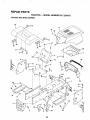
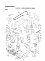
REPAIR PARTS - TRACTOR ................................. 32-47
REPAIR PARTS - ENGINE .................................... 48-55
PARTS ORDERING/SERVICE ................ BACK COVER
SAFETY RULES ............................................................ 2
PRODUCT SPECIFICATIONS ...................................... 3
CUSTOMER RESPONSIBILITIES .... .,,............... 3, 17-20
WARRANTY .................................................................. 3
TRACTOR ACCESSORIES ................ :::;;,,;.................. 5
ASSEMBLY .............................................................. 7-10
OPERATION ........................................................... 11-14
INDEX
A
E
O
Electrical:
Oil:
Cold Weather Conditions ...........15,19
Interlocks and Relays ......................25
Adjustments:
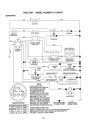
Schematic ............................................
31
Engine .........................................................
19
Brake ..........................................................
23
Storage ...................................................
27
Wiring Diagram .................................
32
Carburetor .............................................
26
Operation ................................................
10-14
Engine:
Mower
Air Filter ..................................... 19-20
Front-To-Back ............................22
Operating Mower ........................................
13
Air Screen .................................................
20
Side-To-Side ...................................
22
Options:
Cooling Fins .........................................
20
Throttle Control Cable .......................
26
Accessories ..........................................5
Oil Change .....................................................
19
Spark Arrester. .....................................
3
Air Filter, Engine ....................................
19-20
Oil Level .......................................... 14
Air Screen, Engine ............................... 20
Oil Type .................................... 14, 19
P
Assembly ............................................. 7-10
Preparation ......................................13
Parking Brake .................................... t2,13
Repair Pads .................................
32-49
Starling .........................................................
15
B
Parts Bag ...............................................................
6
Storage .............................................27
Pads, Replacement/Repair .................
32-49
Battery:
Charging ...............................................
8
Product Specifications .............................. 3
F
Cleaning ..................................................
18
Filter:
Installation ................................................
8
R
Air Filter'.............................................19
Levels ..............................................9,18
Repair Parts ..............................................
32-49
Fuel ................................................................
20
Preparation ..................................................
8
Starting with Weak Battery .......... 24
Fuel:
S
Storage .............................................27
Type .......................................................
15
Terminals ..................................................
18
Storage ..................................................
27
Safety Rules .......................................................
2
Belt:
Fuse ...........................................................
25
Seat ................................................................
8
Motion Drive
Service and Adjustments ....................
21-26
RemovaVReplacement ..............23
H
Carburetor .........................................26
Mower Belt(s)
Fuse ...........................................................
25
Hood
RemovaVInstaltation
....................25
RemovaVReplacement ..............23
Hood Removal/Installation ..............25
Blade:
Motion Drive Belt
L
Sharpening .......................................18
RemovaVReplacement ..............23
Replacement ........................................
18
Leveling Mower Deck ...............................22
Mower Belt(s)
Brake Adjustment .........................................
23
Lubrication:
Removal/Replacement .............
23
Chart .........................................................
17
Mower Adjustment
Front-to.Back .................................
22
C
Engine .....................................................
19
Side-to-Side ........................................
22
Carburetor Adjustment ..............................
26
Mower Removal/Installation ......... 2t
M
Controls, Tractor ..........................................
12
Tire Care ......................................
10,18,24
Maintenance Schedule ..........................22
Customer Responsibilities ...............17-20
Slope Guide Sheet ........................................
57
Mower:
Engine:
Spark Plug(s) ........................................................
20
Adjustment,
Front-to-Back
.............22
Air Filter. ...................................... 19
Specifications...........................................
3
Adjustment, Side-to-Side .............. 22
Air Screen .....................................20
Blade Replacement ...........................
18
Starting the Engine ......................... 14-15
Cooling Fins ............................. 20
Blade Sharpening .......................... 18
Engine Oil .......................................
14,i9
Steering Wheel ................................................
7, 24
Cutting Height ...........................................
13
Fuel Filter _........................................
20
Stopping the Tractor .....................................
13
Installation
..........................................
21
Spark Plug(s) ............................ 20
Storage .........................................................
27
Operation ..........................................14
Tractor.
Removal ...............................................
21
Battery ..............................................
18
T
Blade ................................................
18
Mowing Tips ........................................................
15
Lubrication Chart ..........................
17
Muffler _..........................................................
20
Throttle Control Cable Adjustment ...... 26
Maintenance Schedule ............. 17
Tires ........................................
10, 18, 24
Spark Arrestor ...................................
3,42
Tire Care .......................................
10,18, 24
Trouble
Shooting
Chad
.......................
28-29
Transaxle .........................................
19
Transaxle ............................................................
19
Cutting Height, Mower .............................13
Accessories ....................................................
5
W
4
Warranty ............
:.......................................................
3
Wiring Diagram ........................................32
Wiring Schematic ......................................
31
ACCESSOBI
AND ATTACHMENTS
These accessories and attachments were avaifable through most Sears retail outlets and service centers when the tractor was purchased,.
Most Sears stores can order these items for you when you provide the model number of your tracton
ENGINE
SPARK PLUG
MAINTENANCE
GAS CAN
ENGINEOIL
FUEL STABILIZER
AIR FILTER
BLADES
BELTS
PERFORMANCE
Sears offersa wide variety of attachments that fityour tractor. Many ofthese are listed below with brief explanations of how they can help
you,. This listwas current at the time of publication;however, it may change in future years - more attachments may be added, changes
may be made in these attachments, or some may no longer be available or fit your model Contact your nearest Sears store for the
accessories and attachments that are available for your tractor,
Most of these attachments do not require additional hitches or conversion kits (those that do are indicated) and are designed for easy
attaching and detaching,
SNOW BLADE for snow removal only. 14_inch high, 48-inch wide
bladeclears42-inchpathwhen
angled left orrighL Raises, lowers
with side lever° Adjustabte skids; replaceable, reversible scraper
bar.. (Use with tire chains and wheel weights and/or rear drawbar
weighL)
SNOWTHROWER has 40-inch swath_ Drum-type auger handles
powdery and wet/heavy snow. Mounts easily with simple pin
arrangement. Discharge chute adjusts from tractor seat, 6-inch
diameter spout discharges snow 10 to 50 feet. Lift controlled at
tractor seat. (Use with chains and wheel weights and/or rear
drawbar weight.)
SPRAYERS use 12-voIt DC etectric motor that connects to the
tractor battery or other 12-volt source_ Includes booms for
automatic spraying and hand held wand for spot spraying. Wand
has adjustable spray pattem. For applying herbicides, insecticides, fungicides and liquid fertilizers.
SPREADEPJSEEDERS make seeding, fertilizing, and weed killtng easy. Broadcast spreaders are also useful for granular deIcers and sand.
AERATOR promotes deep root growth for a healthy lawn,. Ta_
pered 2.5-inch steel spikes mounted on 10-inch diameter discs
puncture holes in soil at close intervals to let moisture soak in,
Steel weight tray for increased penetration.
BAGGER lets you collect grass clippings and leaves for a
healthier, neater looking lawn_ Two Permanex containers hold
30-gallon plastic bags.
BUMPER protects front end of tractor from damage..
CARTS make hauling easy. Variety of sizes available, plus
accessories such as side panel kits, tool caddy, cart cover,
protective mat and dolty.
CORING AERATOR takes small plugs out of soil to allow moisture and nutrients to reach grass roots.. 36-inch swath_ 24
hardened steel coring tipso 150 lb. capacity weight tray.
EASY OIL DRAIN VALVE makes oil changes easier, faster.
FRONT NOSE ROLLER canters infront of mower deck to reduce
chances of "scalping" on uneven terrain..
GANG HITCH lets you tow 2 or3 pull-behind attachments at once,
such as sweepers, dethatchers, aerators (not for use with rollers,
carts or other heavy attachments).
GAUGE WHEELS on both sides of the mower deck reduce
chances of "scalping" on uneven terrain. Formower decks notso
equipped,
MULCH RAKE/DETHATCHER loosens soil and flips thatch and
matted leaves to lawn surfacefor easy pickup Twentyspdng line
teeth. Useful toprepare bare areasfor seeding. Available forfront
or rear mounting. HIGH PERFORMANCE REEL-ACTION
SPRING TINE DETHATCHER covers 36-inch wide path and
tosses thatch into large hopper. Mounts behind tractor
MULCHING CLOSE-OUT PLATE KIT, once installed, Iels you
mulch, discharge or bag clippings (bagger optional) without
changing blades. For models not equipped as 3-ira1 Convertible
mowers. See "MOWER" in the Repair Parts section of this
manual.
RAMP TOPS AND FEET let you load and unload tractor from a
pickup track. Use with 2 x 8 or 2 x 10 lumber,
ROLLER for smoother lawn surface. 36-inch wide, 18-inch
diameterwater-tight drum holdsup to390 ibs. ofweight Rounded
edges prevent harm to turf. Adjustable scraper automaticalty
cleans drum.
SWEEPERS let you collect grass clippings and leaves.
TILLER has 5 hp engine and 36-Inch swath toprepare seed beds,
cultivate and compost garden residue,, Tiller has its own built-in
liftand depth controlsystem and does NOT require a sleeve hitch°
Fitsany lawn, yard or garden tractor° Simplyhook up to the tractor
drawbar and gol Optional accessories
convert unit for
dethatching, aerating, hiliing,.owithout tools
TIRE CHAINS are heavy duty; closely spaced extra-large cross
links give smooth ride, outstanding traction,
TRACTOR CAB has heavy duty vinyl fabric over tubular steel
frame, ABS plastictop; clear plastic windshield offers 360 degree
visibility. Hinged metal doors with catch. Keeps operator warm
and dry° Remove vinyl sides and windshields for use as sun
protector in summer° Optional accessories include: tinted/
tempered solid safety glass windshield with hand operated wiper;
t2-vott amber caution light for mounting on cab top_
VACS for powerfulcollectionof heavy grass clippings and leaves.
Optional wand attachment to pick up debris in hard-to-reach
places: VACICHIPPER includes a chIpper-shredder_
WEIGHT BRACKET for drawbar for snow removal applications°
Uses (1) 55 ib. weight
WHEEL WEIGHTS for rear wheels provide needed traction for
snow removal or dozing heavy materials_
5
.....
I
::
tttttl
IIIIIIIgll
i
.......
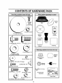
CONTENTS
_:::
.........................
..........
m!t
OF HARDWARE
...................
,llll
Parts
S
ag contents
....................................
illJllllllllllllll
shown illlllllfull jsize
PACK
,i
Parts packed
i
i/llllJlllUllll,,ll
ii
separately
ill
ii
Hj
in carton
.............................
,,,,,,,,,,,
Mulcher
Plate
Seat
Screws
"k_\\/)#10-16
(2)Metal
Sheet
x 1/2
(_
(1) Locknut
3/8-24
(1) Large Flat Washer
Video
Cassette
Steering
Wheel
Steering
Boot
(1) Shoulder
Bolt
5116-18
(1) Hex Bolt
1/2-13 x t
........
Manual
O
........
Parts
,J
Parts Bag
i iii
bag contents
i illl ,ml
not shown
i ii
full size
(1) Lock Washer 1/2
(1) Washer 17/32
x 1-3/16 x 12 Gauge
@
(2) Washers
..............
(2) Lock Washers
Steering Wheel
Adapter'
#10
3/16 x 3/4 x 16 Gauge
(2) Weld Nuts
Screws
Steering
Wheel
Insert
, _,,,i
#10
_
1
_=_
Bushing
teering
(2) Keys
#10 x 5/8
i L[itlli!lltllllUllllllll
(2) Hex Bolts
1/4-20 x 3/4
&
(2) Washers
9/32
(2) Hex Nuts
1/4-20
(2) Latch Hook
Assernblys
Slope Sheet
(2) Lock Washers
1/4
x 5/8 x 16 Gauge
6
,i ,i
LY
Your new tractor has been assembled at the factory with exception of those parts left unassembled for shipping purposes,,
To ensure safe and proper operation of your tractor all parts and hardware you assemble must be tightened securely° Use
the correct tools as necessary to insure proper tightness_
TOOLS REQUIRED FOR ASSEMBLY
A socket wrench set wilt make assembly easier, Standard
wrench sizes are listed.
(1) 5/t6" wrench
(1) 3/4" wrench
(2) 7/16" wrenches
Tire pressure gauge
(t) 1/2" wrench
Utility knife
(1) 9/16" wrench
(1) phillips screwdriver
When right or left hand is mentioned in this manual, it
means when you are in the operating position (seated
behind the steering wheel).
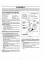
TO REMOVE TRACTOR FROM CARTON
WHEEL
""-------.......___
ADAPTER
,
UNPACK
STEERING
CARTON
•
Remove all accessible loose parts and parts cartons
from carton (See page 6).
=
Cut, from top to bottom, along lines on all four corners
of carton, and lay panels flat.
o
Check for any additional loose parts or cartons and
remove°
SHEET
METAL
TABS
/_
(ASSEMBLY
POSITION)
,,:::
SLOT
BEFORE ROLLING TRACTOR OFFSKID
ATTACH STEERING
°
°
WHEEL (See Fig. 1)
Slide the steering bushing over the steering shaft.
Raise steering shaft forward untilscrew holes in dash
line up with steering bushing° Install two (2) sheet
metal screws and tighten securely_
o
Positionsteering boot over steenng shaft,
°
Place tabs of steering boot over tab slots in dash and
push down to secure,
°
Slide steering wheel adapter ontoupper steering shaff,
•
Positionfront wheels ofthe tractor so they are pointing
straight forward°
Position steering wheel so cross bars are horizontal
(left to right) and slide onto adapter.
Assemble large flat washer and 3/8_24 Iocknut and
tighten securely°
•
°
°
STEERING SHAFT
(SHIPPING POSITION)
FIG, 1
TO ROLL TRACTOR OFF SKID (See Operation section for location and function of controls)
•
Press lift lever plunger and raise attachment lift lever to
its highest position.
°
Release parking brake by depressing clutch/brake
pedal°
Place gearshift lever in neutral (N) position.
Roll tractor backwards off skid,
°
°
Snap steering wheel insert into center of steering
wheel.
•
•
Remove protective materials from tractor hood and
gri&
IMPORTANT:CHECK FOR AND REMOVE ANY STAPLES
tN SKID THAT MAY PUNCTURE TIRES WHERE TRACTOR
IS TO ROLL OFF SKID
7
Remove banding holding discharge guard up against
tractor,.
_u_/iJ/i
, ii i,i,
ill
, ,u,
ii illl ii illlUllllll
Jllnll
IlUllll
........
iilllllllullull
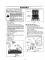
ASSEMBLY
HOW TO SET UP YOUR TRACTOR
CONNECT
BATTERY
SEAT
PAN
(See Figs. 2 and 3)
CAUTION: Do not short battery terminals by allowing a wrench or any other
object to contact both terminals at the
same time. Before connecting battery,
remove metal bracelets, wristwatch
bands, rings, etc.
BOX DOOR
Positive terminal must be connected
first to prevent sparking from accident !! gr°unding; .....
...........
•
°
•
•
•
•
°
Remove cardboard packing from seat pan and lift seat
pan to raised position.
Open battery box door°
Remove terminal protective caps and discard.
FIG. 3
INSTALL
If this battery is put into service after month and year
indicated on label (label located between terminals)
charge battery for minimum of one hour at 6-10 amp&
First connect RED batter,] cable to positive (+) terminal
with hex bolt, fiat washer, lock washer and hex nut as
shown. Tighten securely.
Connect BLACK grounding cable to negative (-) terminal with remaining hex bolt, fiat washer, lock washer
and hex nut° Tighten securely°
Adjust seat before tightening adjustment bolt.
Close battery box door.
Open battery box door for:
° Inspection for secure connections (to tighten hardware),
°
Inspection for corrosion.
•
°
Testing batter,].
Jumping (if required).
•
Periodic charging.
POSITIVE
(RED) CABLE
SEAT (See Fig. 4)
•
•
Remove cardboard packing on seat pan_
Place seat on seat pan and assemble shoulder bolt.
•
Assemble adjustment bolt, lockwasherandflatwasher
Ioosefy. Do not tighten.
°
°
Tighten shoulder bolt securely.
Lower seat into operating position and sit on seat.
=
Slide seat until a comfortable position is reached which
aUows you to press clutch/brake pedal all the way
down.
,
Get off seat without moving its adjusted position.
•
Raise seat and tighten adjustment bolt securely.
SEAT
SEAT PAN
DISCARD
TERMINAL
PROTECTIVE
CAPS
HEX
NUT
SHOULDER
BOLT
LOCK
WASHER
FLAT
WASHER
i
FLAT WASHER
HEX
BOLT
ADJUSTMENT
BOLT
WASHER
FIG. 4
NEGATIVE
(BLACK) CABLE
FIG. 2
8
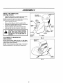
ASSE
INSTALL MULCHER
(See Figs. 5 and 6)
o
BLY
PLATE
Install two latch hooks to mulcher plate using screw,
washer, lock washer, and weld nut as shown,
NOTE: Pre-assemble weld nut to latch hook by inserting
weld nut from the top with hook pointing down,
LOCK
WASHER
WELD.
•
°
Tighten hardware securely.
Raise and hold deflector shield in upright position.
•
Place front of mulcher plate over front of mower deck
opening and slide into place, as shown_
Hook front latch into hole on front of mower deck.
°
•
HOOK POINTS
DOWN
WELD NUT
FROM THE TOP
.UT \
"_
_
SCREW
LATCH
HOOK
HOOK
Hook rear latch into hole on back of mower deck.
ii i
....
: ...............................
guard from mower. Raise and hold
CAUTION:
not remove
discharge
guard whenDoattaching
mulcher
plate
and allow it to rest on plate while in
operation.
iii
I
I'1/
i,i iiiii i,ii, II
TO CONVERT TO BAGGING
DISCHARGING
i
i
LOCK
WASHER
WELD
NUT
WASHER
WASHER
MULCHER
PLATE
OR
_SCREW
FIG. 5
DEFLECTOR
SHIELD
Simply remove mulcher plate and store in a safe place.
Your mower is now ready for discharging or installation of
optional grass catcher accessory,
NOTE: It is not necessaryto change blades. The mulcher
blades are designed for discharging and bagging alsoo
LATCH
HOOKS
FIG. 6
9
ASSEMBLY
,/CHECKLIST
CHECK TIRE PRESSURE
BEFORE YOU OPERATE AND ENJOY YOUR NEW
TRACTOR, WE WISH TO ASSURE THAT YOU RECEIVE
THE BEST PERFORMANCE AND SA TfSFA CTION FROM
THIS QUALITY PRODUCT,
The tires on your tractor were overinflated at the factory for
shipping purposes. Correct tire pressure is important for
best cutting performance_
°
Reduce tire pressure to PSi shown in "PRODUCT
SPECIFICATIONS" on page 3 of this manual
PLEASE REVIEW THE FOLLOWING CHECKLIST:
CHECK DECK LEVELNESS
For best cutting results, mower housing should be properly
leveled. See 'q'O LEVEL MOWER HOUSING" in the
Service and Adjustments section of this rnanual.
CHECK
BELTS
FOR PROPER
POSITION
/
,/
All assembly instructionshave been completed°
No remaining loose parts in carton.
v"
Batteryis properly prepared and charged. (Minimum
1 hour at 6 amps)o
Seat is adjusted comfortably and tightened securely.
,/
OF ALL
v"
See the figures that are shown for' replacing motion and
mower blade drive belts in the Service and Adjustments
section of this manual° Verify that the belts are routed
correctly,
All tires are properly inflated. (For shipping purposes,
the tires were overmflated at the factory).
/
Be sure mower deck is properly leveled side-to-side/
front-to-rear for best cutting results. (Tires must be
properly inflated for leveling).
V" Check mower' and drive belts. Be sure they are routed
properly around pulleys and inside all belt keepers.
CHECK BRAKE SYSTEM
,/
Check wiring_ See that all connections are still secure
and wires are properly clamped.
WHILE LEARNING HOW TO USE YOUR TRACTOR, PAY
EXTRA A TTENTION TO THE FOLLOWING IMPORTANT'
ITEMS:
After you learn how to operate your tractor, check to see
that the brake is properly adjusted_ See '_TO ADJUST
BRAKE" in the Service and Adjustments section of this
manual
/
Engine oil is at proper' level,
v'
Fuel tank is filled with fresh, clean, regular unleaded
gasoline.
Become familiar with all controls - their location and
function, Operate them before you start the engine_
,/
/
10
Be sure brake system is in safe operating condition.
OPERATION
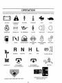
These symbols may appear on your tractor or in literature supplied with the product_ Learn and understand
their meaning°
BATTERY
CAUTION OR
WARNING
REVERSE
FORWARD
FAST
SLOW
ENGINE ON
ENGINE OFF
OIL PRESSURE
CLUTCH
LIGHTS ON
L_GHTS OFF
FUEL
CHOKE
MOWER HEIGHT
DIFFERENTIAL
LOCK
PARKING BRAKE
LOCKED
UNLOCKED
L
REVERSE
MOWER LIFT
NEUTRAL
ATTACHMENT
CLUTCH ENGAGED
HIGH
LOW
ATTACHMENT
CLUTCH DISENGAGED
PARKING BRAKE
IGNITION
HYDROSTATIC FREE WHEEL
(Hydro Models only)
DANGER, KEEP HANDS AND FEET AWAY
111
iii
iiiilu
OPERATION
.....................................................
iiii
i i
iiiiiiiiii
ii
_1i
i1,,
ii iii.,
i iiiiiii1,,i
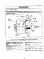
KNOW YOUR TRACTOR
READ THIS OWNER'S
MANUAL AND SAFETY RULES BEFORE OPERATING
YOUR TRACTOR
Compare the illustrationswith your tractorto familiarize yourselfwith the locations of various controls and adiustmentso Save
this manual for future reference.
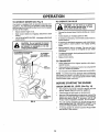
IGNITION
AMMETER
ATTACHMENT
CLUTCH LEVER
SWITCH
LIGHT
SWITCH
LIFTLEVER
PLUNGER
THROTTLE/
CHOKE
CONTROL
ATTACHMENT
L]FT LEVER
o
CLUTCW
BRAKE
PEDAL
MOWER DECK
HEIGHT ADJUSTMENT
PARKING
BRAKE
GEARSHIFT
LEVER
FIG. 7
Our tractors conform to the safety standards of the American National Standards Institute
ATTACHMENT CLUTCH LEVER: Used to engage the
mower blades, or other' attachments mounted to your
tractor_
LIGHT SWITCH: Turns the headlights on and off.
THROTTLE/CHOKE CONTROL: Used for starting and
controllingengine speed,
CLUTCH/BRAKE PEDAL: Used for declutching and braking the tractor and starting the engine°
PARKING BRAKE: Locks clutch/brake pedal into the
brake position°
GEARSHIFT LEVER: Selects the speed and direction of
tractor.
ATTACHMENT LIFT LEVER: Used to raise, lower, and
adjust the mower deck or other attachments mounted to
your tractor.
LIFT LEVER PLUNGER: Used to release attachment tilt
lever when changing its position.
IGNITION SWITCH: Used for starting and stopping the
engine.
AMMETER: Indicates battery charging (+) or discharging
(-)
illl.................
OPERATI
m,,ll,ll,lll,l,lll ,,
ill i i
ill
, ,ill, i
The operation of any tractor can result in foreign objects thrown into the eyes, which
can result in severe eye damage. Always wear safety glasses or eye shields while
operating your tractor or performing anyadjustments or repairs. We recommend awide
vision safety mask over the spectacles or standard safety glasses.
i,i
ii,ll,,llll
,i _ll i
_1
HOW TO USE YOUR TRACTOR
TO SET PARKING
I'l'M'l'll'llll
BRAKE (See Fig. 8)
Your tractor is equipped with an operator presence sensing
switch. When engine is running, any attempt by the
operator to leave the seat without first setting the parking
brake will shut off the engine°
•
Depress clutch/brake pedal into full "BRAKE" position
and hold.
II
IIII
TO USE THROTTLE
L ill
II
!!1
'11
CONTROL
I
I
I
!1,11 ,i I
(See Fig. 8)
Always operate engine at full throttle,
"DISENGAGED"
POSITION
IGNITION
KEY
•
Operating engine at less than full throttle reduces the
battery charging rate.
°
Full throttle offers the best bagging and mower performanceo
TO MOVE FORWARD
(See Fig. 8)
THROTTLE/CHOKE
CONTROL LEVER
PARKING
BRAKE
"ENGAGED"
POSITION
°
TO ADJUST MOWER CUTTING
(See Fig. 8)
PARKING BRAKE
"DISENGAGED" POSITION
HEIGHT
The position of the attachment lift lever determines the
cutting height°
FIG, 8
•
°
(See Fig. 8)
Grasp lift lever.
Press plunger with thumb and move lever to desired
position.
The cutting height range is approximately 1-1/2 to 4",.The
heights are measured from the ground to the blade tip with
the engine not running. These heights are approximate
and may vary depending upon soil conditions, height of
grass and types of grass being mowed_
MOWER BLADES Move attachment clutch lever to "DISENGAGED" position.
GROUND DRIVE •
Depress clutch/brake pedal into fult "BRAKE" position..
•
Move gearshift lever to neutral (N) position
ENGINE •
Move throttle control to slow position°
NOTE: Failure to move throttle control to slow position and
allowing engine to idle before stopping may cause engine
to "backfire",.
•
Turn ignition key to "OFF" position and remove key.
Always remove key when leaving tractor to prevent
unauthorized use.
°
Never use choke to stop engine.
Start tractor with clutch/brake pedal depressed and
gearshift lever in neutral (N) position.
•
Move gearshift lever to desired position.
o Slowly release clutch/brake pedal to start movement.
IMPORTANT: BRING TRACTOR TO A COMPLETE STOP
BEFORE SHIFTING OR CHANGING GEARS. FAILURE
TO DO SO WELLSHORTEN THE USEFUL LIFE OF YOUR
TRANSAXLE.
"BRAKE"
POSITION
CLUTCH/BRAKE PEDAL
"DRIVE" POSITION
AND BACKWARD
The direction and speed of movement is controlled by the
gearshift lever.
GEARSHIFT
LEVER
STOPPING
ll'lll'_'
iA ...............
............
Place parking brake lever in "ENGAGED" position and
release pressure from clutch/brake pedal Pedal should
remain in "BRAKE" position. Make sure parking brake
will hold tractor secure,.
ATTACHMENT CLUTCH LEVER
"ENGAGED" POSITRON
'l'
CAUTION: Always stop tractor completely, as described above, before leaving the operator's position; to empty
grass catcher, etc.
I1'1!1'1' IU' !IL'
.
II
NOTE: Under certain conditions when tractor is standing
idlewith the engine running, hot engine exhaust gases may
cause "browning" of grass. To eliminate this possibility,
always stop engine when stopping tractor on grass areas.
°
•
•
13
The average lawn should be cut to approximately 2-1/2
inches during the cool season and to over 3 inches
during hot months. For healthier and better looking
lawns, mow often and after moderate growth°
For best cutting performance, grass over 6 inches in
height should be mowed twice. Make the first cut
relatively high; the second to desired height°
i illlll
iilll
...............................
TO OPERATE
....
MOWER (See Fig. 9)
TO OPERATE
Your tractor is equipped with an operator presence sensing switch Any attempt by the operator to leave the seat
with the engine running andthe attachment clutcit engaged
will shut off the engine.
-
Select desired height of cut
•
Start mower blades by engaging attachment clutch
control
TO STOP MOWER BLADES - disengage attachment
clutch control
•
!_
without either the entire grass catcher,
on
mowers Do
so not
equipped,
disCAUTION:
operate or
thethe
mower
charge guard in place.
ATTACHMENT CLUTCH LEVER
"DISENGAGED" POSITION
"ENGAGED"
POSITION
O,_
I
:
ON HILLS
hills with slopes greater than 15 ° and
..................
CAUTION:
not any
driveslope
up or down
do not drive Do
across
i
Ill
ttll
, i Jl,Jl,i, I
,,
,i
...........
l
It tl
{
t t,
Choose the slowest speed before starting up or down
hills
"
!
Avoid stopping or changing speed on hills
If slowing ts necessary, move throttle control lever to
slower position
tf stopping is absolutely necessary, push clutch/brake
pedal quickly to brake position and engage parking
brake
Move gearshift lever to 1st gear Be sure you have
aIJowed room for tractor to rol_ slightly as you restart
movement.
To restart movement, slowly release parkingbrake and
clutch/brake pedal
ATTACHMENT
LIFT LEVER
HIGH POSITION
Make all turns slowly
TO TRANSPORT
•
Raise attachment lift to highest position with attach_
ment lift control
•
When pushing or towing your tractor, be sure gearshift
lever is in neutral (N) position
•
Do not push or tow tractor at more than five (5) MPH
NOTE: To protect hood from damage when transporting
your tractor on a truck or a trailer, be sure hood is closed
and secured to tractor Use an appropriate means of tying
hood to tractor (rope, cord, etc)
BEFORE STARTING THE ENGINE
CHECK ENGINE OIL LEVEL (See Fig. 14)
•
The engine in your tractor has been shipped, from the
factory, already filled with summer weight oil,
•
•
Check engine oil with tractor on level ground
Remove oil fill cap/dipstick and wipe clean, reinsert the
dipstick and screw cap tight, wait for a few seconds,
remove and read oil level If necessary, add oil until
"FULL' mark on dipstick is reached. Do not overfill
•
For' cold weather operation you should change oil for
easier starting (See "OIL VISCOSITY CHART" in the
Customer Responsibilities section of this manual)°
•
To change engine oil, see the Customer Responsibilities section in this manual
DISCHARGE
GUARD
FIG. 9
14
OPEBATION
ADD GASOLINE
COLD WEATHER STARTING ( 50 ° F and below)
° When engine starts, allowengine to run with the throttle
control in the choke position until the engine runs
roughly, then move throttle control to fast position. This
may require an engine warm-up period from several
seconds to severalminutes, depending on the temperature.
°
Fill fuel tank, Use fresh, clean, regular unleaded
gasoline with a minimum of 87 octane, (Use of leaded
gasoline will increase carbon and lead oxide deposits
and reduce valve life). Do not mix oil with gasoline.
Purchase fuel in quantities that can be used within 30
days to assure fuel freshness
IMPORTANT: WHEN OPERATING IN TEMPERATURES
BELOW 32°F(0°C), USE FRESH, CLEAN WINTER GRADE
GASOLINE TO HELP INSURE GOOD COLD WEATHER
STARTING.
°
NOTE: If at a high altitude (above 3000 feet) or in cold
temperatures (below 32 F) the carburetor fuel mixture may
need to be adjusted for best engine performance. See '%0
ADJUST CARBURETOR" in the Service and Adjustments
section of this manual_
WARNING: Experience indicates that alcohol blended
fuels (called gasohol or using ethanol or methanol) can
attract moisture which leads to separation and formation of
acids during storage° Acidic gas can damage the fuel
system of an engine while in storage. To avoid engine
problems, the fuel system should be emptied before storage of 30 days or longer, Drain the gas tank, start the
engine and let it run until the fuel lines and carburetor are
empty. Use fresh fuel next season. See Storage Instructions for additional information. Never use engine or
carburetor cleaner products in the fuel tank or permanent
damage may occur.
MOWING TIPS
•
Tire chainscannot be used when the mower housingis
attached to tractor°
°
Mower should be properly leveled for best mowing
performance. See'TO LEVEL MOWER HOUSING" in
the Service and Adjustments section of this manual.
The left hand side of mower should be used for trimmingo
°
CAUTION: Fill to bottom of gas tank
filler neck. Do not overfill. Wipe off any
spilled oil or fuel. Do not store, spill or
use gasoline near an open flame.
•
Drive so that clippings are discharged onto the area
that has been cut. Have the cut area to the right of the
machine. This will result in a more even distribution of
clippings and more uniform cutting.
o
When mowing large areas, start by turning to the right
so that clippings will discharge away from shrubs,
fences, driveways, etch After one or two rounds, mow
in the opposite direction making left hand turns until
finished (See Fig. 10)_
o
If grass is extremely tall, it should be mowed twice to
reduce load and possible fire hazard from dried ctipdpingsoMake first cut relatively high; the second to the
esired height.
•
Do not mow grass when it is wet° Wet grass will plug
mower and leave undesirable clumps. Allow grass to
dry before mowing°
°
Always operate engine at full throttle when mowing to
assure better mowing performance and proper discharge of material. Regulate ground speed by selecting a low enough gear to give the mower cutting
performance as well as the quality of cut desired.
°
When operating attachments, select a ground speed
that will suit the terrain and give best performance of
the attachment being used.
TO START ENGINE (See Fig. 8)
When starting the engine for the first time or if the engine
has run out of fuel, it will take extra cranking time to move
fuel from the tank to the engine.
°
Sit on seat in operating position, depress clutch_rake
pedal and set parking brake,
.
Place gear shift lever in neutral (N) position,
°
Move attachment clutch to "DISENGAGED" position.
•
Move throttle control to choke position.
Note: Before starting, read the warm and cold starting
procedures below.,
•
The attachments can also be used during the engine
warm-up period,
Insert keyinto ignition and turn key clockwise to"START"
position and release key as soon as engine starts° Do
not run starter continuously for more than fifteen seconds per minute. If the engine does not start after
several attempts, move throttle control to fast position,
wait a few minutes and try again. If engine still does not
start, move the throttle control back to the choke
position and retry.
f
WARM WEATHER STARTING (50 ° F and above)
° When engine starts, move the throttle control to the fast
position.
°
The attachments and ground drive can now be used, If
the engine does not accept the load, restart the engine
and allow itto warm up for one minute using the choke
as described above°
(
FIG. 10
15
..
illlll ....
iilllll illlllllll
iilll
iii
.....................................................
OPERATION
/!llllll
i
MULCHING
MOWING
.................
.......
...........
lUlt
TIPS
•
IL
//
I'll
I .................
Forbestresutts,
adjustthemowercuttingheightsothat
the mower cuts off only the top one-third of the grass
blades (See Figo!1 )_ For extremely heavy mulching,
reduceyourwidthof cuton each pass and mow slowly,,
IMPORTANT:
FOR BEST PERFORMANCE, KEEP
MOWER HOUSING FREE OF BUILT-UP GRASS AND
TRASH_ CLEAN AFTER EACH USE_
•
III1'
The special mulching blade will recut the grass clippings many times and reduce them in size sO that as
they fall onto the lawn they will disperse into the grass
and not be noticed° Also, the mulched grass will
biodegrade quickly to provide nutrients for the lawn.
Always mulch with your' highest engine (blade) speed
as this will provide the best recutting action of the
blades.
•
Certain types of grass and grass conditions may require that an area be mulched a second time to
completely hide the clippings. When doing a second
cut, mow across or perpendicular to the first cut path.
•
Change your cutting pattern from week to week. Mow
north to south one week then change to east to west the
next week., This will help prevent matting and graining
of the lawn.
Avoid cutting your lawn when it is wet. Wet grass tends
to form clumps and interferes with the mulching action_
The best time to mow your lawn is the early afternoon.
At this time the grass has dried and the newly cut area
will not be exposed to the direct sun.
MAX I/3
FIG_ 11
1R
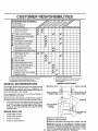
CUSTOMER RESPO
BILUTIES
i
Check
Brake
Oporat on
Check
.
Tire Pressure
Check for LooseFasteners
c
.
,
_'
i
T
Check BatteryLevel/Recharge
0
Clean Battery and Terminals
CheckEngineOil Level
G
I
N
Change EngineOi'
CleanAir Filter
CleanAir Screen
inspectMuffler!SparkArrester
Replace Oil Filter(if equipped)
-
_
,
IV #'
_
$/_'1_'.3
.....
.....
"
1_'
_2 .......
'
'
'
' ...... ' _.2
'"
:_/2'
' '
_#' _1'
_4'2 '
'
--
i"
"
'
"
"
5 - {f equipped with adjustab{e system
6 - Not required it equipped with maintenance-free battery.
7 - Tighten front axle pivot bolt to 35 it .Ibs maximum
Do not overtighten.
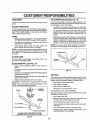
LUBRICATION
(_SPINDLE
CHART
ZERK_
SPINDLE ZERK (_)
(_ FRONT WHEEL"_._'_:I
BEARING ZERK
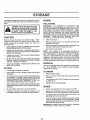
Once a year you should replace the spark plug, clean
or replace air filter, and check blades and belts for
wear. A new spark plug and clean air filter assure
proper air-fuel mixture and help your engine run better
and last longer,,
(_ATTACHMENT_
_
_
RONT WHEEL (_)
==========================
BEARING ZERK
._
::::::::::::::'
_
EACH USE
Check brake operation,,
Check tire pressure,
Checkfor loose fasteners,
'i
.
Some adjustments will need to be made periodically to
properly maintain your tractor,
All adjustments in the Service and Adjustments section of
this manual shouid be checked at least once each season.
•
°
.
'
Lv' ii[ii_
RECOMMENDATIONS
Check engine oil level
'
........
i_ ..........
Fins
"
Replace SparkPlug
Replace Air Filter PaperCartridge ....
•
'
_/S ................
Ks
The warranty on this tractor does not cover items that have
been subjected to operator abuse or negligence. To
receive full value from the warranty, operator must maintain
tractor as instructed in this manual
BEFORE
''
_/
Change more often when operating under a heavy load or in high ambient temperatures
Service more often when operating indirty
or dusty conditions
If equipped with oilf_ter, change olievery 50 hours_
Replace blades more often when mowing in sandy soil.
GENERAL
1
_
ReplaceFue!Filter
i
2
3
4
I_
il{
Adjust Blade Belt(s) Tension
Adjust Motion Drive Belt(s)Tension
E
_ .
!_'7
-ii
R checkfrans_le cooling
U
, ,
_
ENG,
NE®
_GEARSH'_O
PIVOTS
(_)SAE 30 OR I0W30 MOTOR OIL
(_)GENERAL
PURPOSE GREASE
(_)REFER TO CUSTOMER RESPONSIBILITIES
17
"ENGINE"
SECTION
IMPORTANT:
DO NOT OIL OR GREASE THE PIVOT POINTS
WHICH HAVE SPECIAL NYLON BEARINGS°
VISCOUS LUBRICANTS WILL ATTRACT DUST AND DIRT THAT WILL SHORTEN
THE LIFE OF THE SELF-LUBRICATING
BEARINGS,
IF YOU
FEEL THEY MUST BE LUBRICATED,
USE ONLY A DRY, POWDERED GRAPHITE TYPE LUBRICANT SPARINGLY.
R
.....
,,,,.....
ill,
,,
i i, i,,,,,,
,i
BILITIES
lllllll
i
:
ill
ii
=
i
TRACTOR
TO SHARPEN
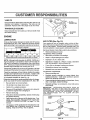
Always observe safety rules when performingany maintenance.
Care shoufd be taken to keep the blade balanced. An
unbalanced blade will cause excessive vibration and eventual damage to mower and engine_
BRAKE OPERATION
°
The blade can be sharpened with a file or on a grinding
wheel Do not attempt to sharpen while on the mower,
°
To check blade balance, you wilt need a 5/8" diameter
steel bolt, pin, or a cone balancer,, (When using a cone
balancer, follow the instructions supplied with balancer).
°
Slide blade on to an unthreaded portionof the steel bolt
or pin and hold the bolt or pin parallel with the ground.
If blade is balanced, it should remain in a horizontal
position,. If either end of the blade moves downward,
sharpen the heavy end until the blade is balanced,.
If tractor requires more than six (6) feet stopping distance
at high speed in highest gear, then brake must be adjusted.
(See 'q'O ADJUST BRAKE" in the Service and Adjustments section of this manual).
TIRES
•
Maintain proper air pressure in all tires (See "PRODUCT SPECIFICATIONS on page 3 of this manual).
=
Keep tires free ef gasoline, oil, or insect control chemicals which can harm rubber.
•
Avoid stumps, stones, deep ruts, sharp objects and
other hazards that may cause tire damage°
BLADE (See Fig. 13)
NOTE: Do not use a nail for balancing blade. The lobes of
the center hole may appear to be centered, but are not
NOTE: To seal tire punctures and prevent flat tires due to
slow leaks, tire sealant may be purchased from your local
parts dealer_ Tire sealant also prevents tire dry rot and
corrosion.
CENTER HOLE
/
/
BLADE CARE
For' best results mower' btades must be kept sharp_ Replace bent or damaged blades.
BLADE REMOVAL
5/8" BOLT
OR PiN
(See Fig. 12)
°
Raise mower to highest position to allow access to
blades.
.
Remove hex bolt, lock washer and flat washer securing blade.
.
Install new or resharpened blade with trailing edge up
towards deck as shown.
•
Reassemble hex bolt, lock washer and flat washer in
exact order as shown.
J
FIG. 13
BATTERY
Your tractor has a battery charging system which is sufficient for normal use. However, periodic charging of the
battery with an automotive charger will extend its life.
.
Tighten bolt securely (30-35 Ft. Lbs, torque).
IMPORTANT: BLADE BOLT 1SGRADE 8 HEATTREATED,,
NOTE: We do not recommend sharpening blade - but if
,ou do, be sure the blade is balanced.
MANDREL
ASSEMBLY
BLADE
BLADE
°
•
Keep battery and terminals clean.
Keep battery bolts tight.
•
Keep small vent holes open.
°
Recharge at 6-10 amperes for1 houL
TO CLEAN BATTERY AND TERMINALS
Corrosion and dirt on the battery and terminals can cause
the battery to "leak" power.
TRAILING
EDGE UP
LOCK WASHER
',HEX BOLT (GRADE 8)*
*A GRADE 8 HEAT TREATED BOLT CAN BE
IDENTIFIED BY SIX LINES ON THE BOLT HEAD.
FIG. 12
18
=
Open battery box door.
•
Disconnect BLACK battery cable first then RED battory cable and remove battery from tractor,
°
Rinse the battery with plain water and dry,
•
Clean terminals and battery cable ends with wire brush
until bright.
•
°
Coat terminals with grease or petroleum jelly,
Reinstatl battery (See "CONNECT BATTERY" in the
Assembly section of this manual).
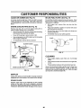
CUSTOIVlE
V-BELTS
OIL FILL
CAP/DIPSTICK
Check V_belts for deterioration and wear after 100 hours of
operation and replace if necessary The belts are not
adjustable Replace belts if they begin to slip from wear
TRANSAXLE
/
COOLING
Keep transaxle free from build-up of dirt and chaff which
can restrict cooling.
OIL DRAIN
PLUG
ENGINE
FIG. 14
LUBRICATION
AIR FILTER (See Fig. 15)
Only use high quality detergent oil rated with AP1 service
classification SF, SG, or SH Select the oil's SAE viscosity
grade according to your expected operating temperature
Your engine will not run properly using a dirty air filter,
Clean the foam pre-cleaner after every 25 hours of operation or every season. Service paper cartridge every 100
hours of operation or every season, whichever occursfirsL
SAE ViSCOSiTY GRADES
_f.,1=Ilk
Service air cleaner more often under dusty conditions_
.
Remove knob(s) and cover.
TO SERVICE PRE-CLEANER
_.
4
OF
.20_
TEMPERATURE
O=
30"
32= 40°
RANGE ANTtGIPATED
60"
80"
100°
BEFORE NEXT OIL CHANGE
NOTE: Although multi viscosity oils (5W30, 10W30 etch)
improve starting in cold weather, these muftiwiscosity oils
wilt result in increased oil consumption when used above
32°F Check your engine oil leve! more frequently to avoid
possible engine damage from running low on oil
Change the oil after every 25 hours of operation or at least
once a yearif the tractoris not used for25 hours in oneyear
•
Remove oil fill cap/dipstick Be careful not to allow dirt
to enter the engine when changing oil
.
Remove drain plugo
°
After oil has drained completely, replace oil drain plug
and tighten securely
•
Refill engine with oil through oil fil! dipstick tube Pour
sIowly Do not overfill For approximate capacity see
PRODUCT SPECIFICATIONS
on page 3 of this
manual°
°
o
=
Wash it in liquid detergent and water
Squeeze it dry in a clean cloth°
°
Saturate it in engine oil Wrap it in cEean, absorbent
cloth and squeeze to remove excess oil
o
°
If very dirty or damaged, replace pre-cieanero
Reinstall pre cleaner over cartridge
°
TO CHANGE ENGINE OIL (See Fig 14)
Determine temperature range expected before oil change°
All oil must meet API service classification SF, SG or SHo
•
Be sure tractor is on Ievel surface
Oil will drain more freely when warm
Catch oil in a suitable container
Slide foam pre-cleaner off cartridge
= Reinstaif cover and secure with knob(s)
TO SERVICE CARTRIDGE
= Remove cartridge nut
Check the crankcase oil level before starting the engine
and after each eight (8) hours of operation° Tighten oil fill
cap/dipstick securely each time you check the oil level
•
•
°
=
Carefully remove cartridge to prevent debris from
entering carburetor Clean base carefully to prevent
debris from entering carburetor
Clean cartridge bytapping gentlyon flat surface If very
dirb/or damaged, replace cartridge
o
Reinstall cartridge, nut, precleaner, cover and secure
with knob(s)
IMPORTANT:
PETROLEUM SOLVENTS SUCH AS
KEROSENE, ARE NOT TO BE USED TO CLEAN THE
CARTRIDGE. THEY MAY CAUSE DETERIORATION OF
THE CARTRLDGEo DO NOT OIL CARTRIDGE DO NOT
USE PRESSURIZED
AIR TO CLEAN OR DRY
CARTRIDGE°
KNOB
CARTRIDGE
NUT
COVER
Use gauge on oil fill cap/dipstick for checking level Be
sure dipstick cap is tightened securely for accurate
reading° Keep oil at 'FULL line on dipstick
PAPER
CARTRIDGE
FOAM
_BASE
19
FIG. 15
NSIBILITIES
,,i
I
IIIIII
JIIIII
I
Jill
CLEAN AIR SCREEN
....
.....
(See Fig. 16)
IN-LINE FUEL FILTER
Air screen must be kept free of dirt and chaff to prevent
engine damage from overheating, Clean with a wire brush
or compressed air to remove dirt and stubborn dried gum
fibers_
ENGINE COOLING
The fuel filter should be replaced once each season. If fuel
filter becomes clogged, obstructing fuel flow to carburetor,
replacement is required°
FINS (See Fig. 16)
Remove any dust, dirt or oil from engine cooling fins to
prevent engine damage from overheating.
•
Remove screws from blower housing and lift housing
and dipstick tube assembly off engine.
•
Cover oil fill opening to prevent entry of dirt.
•
Use compressed air or stiff bristle brush to thoroughly
clean engine cooling fins.
(See Fig. 17)
•
With engine cool, remove _ter and plug fuel line
sections.
•
Place new fuel filter in position in fue! line with arrow
pointing towards carburetor.
Be sure there are no fuel line leaks and clamps are
properly positioned.
•
•
Immediately wipe up any spilled gasoline,,
CLAMP
To reassemble, reverse above procedure.
SCREWS
BLOWER HOUSING
SCREWS
___D
CLAMP
FUEL
RLTER
FIG. 17
AIR SCREEN
OIL FILL
TUBE
ASSEMBLY
CLEANING
SPARK
PLUG
ENGINE COOLING FINS
•
Cfean engine, battery, seat, finish, etc, of all foreign
matter.
•
Keep finished surfaces and wheels free of all gasoline,
oil, etc.
•
Protect painted surfaces with automotive type wax.
We do not recommend using a garden hose to clean your
tractor uniess the electrical system, muffler', air lifter and
carburetor are covered to keep water out. Water' in engine
can result in a shortened engine life.
FIG, 16
MUFFLER
Inspect and replace corroded muffler and spark arrester (if
equipped) as it could create a fire hazard and/or damage_
SPARK PLUGS
Replace spark plugs at the beginning of each mowing
season or' after every 100 hours of operation, whichever
occurs first. Spark plug type and gap setting are shown in
"PRODUCT SPECIFICATIONS" on page 3 ofthis manual.
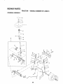
2O
SERVICE AND ADJUSTMENTS
i i, i
rllllll
.......
CAUTION: BEFORE PERFORMING ANY SERVICE OR ADJUSTMENTS:
o
o
O
Q
o
@
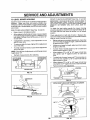
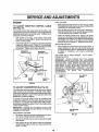
TO REMOVE
Depress clutch/brake pedal fully and set parking brake.
Place gearshift lever in neutral (N) position.
Place attachment clutch in "DISENGAGED" position.
Turn ignition key "OFF" and remove key.
Make sure the blades and all moving parts have completely stopped.
Disconnect spark plug wire from spark plug and place wire where it cannot come in contact with
plug,
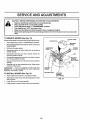
MOWER (See Fig. 18)
CLUTCH LEVER
Mower willbe easier to remove from the rightside of tractor
o
•
Place attachment clutch in "DISENGAGED" position°
Move attachment liftlever forward to lowermower to its
lowest position.
°
Roll belt off engine pulley_
°
Disconnect clutch rod from clutch lever by removing
retainer spring_
Disconnect anti-sway bar from chassis bracket by
removing retainer spring.
o
RETAINER
SUSPENSION
ARMS
°
Disconnect suspension arms from rear deck brackets
by removing retainer springsr
°
Disconnect front links from deck by removing retainer
springs°
ENGINE
PULLEY
_i\
Raise lift lever to raise suspension arms° Slide mower
out from under tractor.
IMPORTANT:
IF AN ATTACHMENT OTHER THAN THE
MOWER IS TO BE MOUNTED TO THE TRACTOR,
REMOVE THE FRONT LINKS_
RETAINER
SPRINGS
(BOTH SIDES)
•
RETAINER
SPRING
/
ANTI-SWAY BAR
TO INSTALL MOWER (See Fig. 18)
•
Raise attachment lift lever to its highest position..
•
Slide mower undertractorwith
side of tractor,
°
°
Lower lift lever to its lowest position.
Install mower in reverse order of removal instructions_
discharge guard to right
RETAINER
SPRINGS
(BOTH SIDES)
FIG. 18
21
AND ADJUSTMENTS
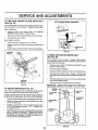
FRONT-TO-BACK ADJUSTMENT (See Figs., 2t and 22)
IMPORTANT: DECK MUST BE LEVEL SIDE.TO-SIDE. 1F
THE FOLLOWING FRONT-TO-BACK ADJUSTMENT tS
NECESSARY, BE SURE TO ADJUST BOTH FRONT LINKS
EQUALLY SO MOWER WILL STAY LEVEL SIDE-TOSIDE
TO LEVEL MOWER HOUSING
Adjust the mower while tractor is parked on level ground or
driveway. Make sure tires are properly inflated (See
"PRODUCT SPECIFICATIONS" on page 3 of this manual).
If tires are over or' underinflated, you will not properly adjust
your mower.
SIDE-TO-SIDE ADJUSTMENT (See Figs. 19 and 20)
o Raise mower to its highest position.
•
At the midpoint of both sides of mower, measure height
"
"A"on
from bottom edge of mower to ground_ D_stance
'
" " 1/ 4"
both stdes
of mower should be the same or within
of each other
-
If adjustment is necessary, make adjustment on one
side of mower only.
To raise one side of mower, tighten lift link adjustment
nut on that side.
•
•
To obtain the best cutting results, the mower housing
should be adjusted so that the front is approximately 1/8" to
1/2" lower than the rear when the mower' is in its highest
position,
Check adjustment on right side of tractor, Measure distance "D" directly in front and behind the mandrel at bottom
edge of mower housing as shown.
°
Before making any necessary adjustments, check that
both front links are equal in length., Both links should
be approximately 10-3/8'L
If links are not equal in length, adjust one link to same
length as other link.
•
To lower front of mower loosen nut "E" on both front
links an equal number of turns.
•
When distance "D" is 1/8" to 1/2" lower at front than
rear, tighten nuts "F" against trunnion on both front
links.
•
To raise front of mower, loosen nut"F' from trunnion on
both front links. Tighten nut "E" on both front links an
equal number of turns.
•
When distance "D" is 1/8" to 1/2" lower at front than
rear, tighten nut"F" against trunnion on both front links,
•
Recheck side-to-side adjustment.
To lower one side of mower, loosen lift link adjustment
nut on that side°
NOTE: Each full turn of adjustment nut will change mower
height about 1/8'L
•
Recheck measurements after adjusting.
BOTTOM EDGE
OF MOWER TO
GROUND
BOTTOM EDGE
OF MOWER TO
GROUND
A
MANDREL
oo, "',
GROUND LINE
FIG. 19
SUSPENSION
ARM
FIG. 21
BOTH FRONT LINKS MUST BE EQUAL IN LENGTH
LIFT LINK
ADJUSTMENT
NUT
FIG. 20
NUT
NUT "F" __:___"
FRONT LINKS
22
TRUNNION
FIG, 22
mrl'"m i
_
i,,,,,,,iuul.....
_,
CE AND ADJUSTMENTS
''
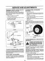
TO REPLACE
(See Fig. 23)
MOWER
i
,,,i,u_u ,,11 i
...................
BLADE DRIVE BELT
ii, t
.........
i,,
i
WITH PARKING BRAKE "ENGAGED"
The mower blade drive belt may be replaced without tools°
Park the tractor on level surface° Engage parking brake°
BELT REMOVAL o
•
Remove mower from tractor (See "TO REMOVE
MOWER" in this section of this manual),,
Work belt off both mandret pulleys and idler pulleys_
NUT "A"
JAM NUT
.
Pult belt away from mower.
BELT INSTALLATION
°
Install new belt in reverse order of removal
=
°
Make sure belt is in all pulley grooves and insideall belt
guides,
install mower in reverse order of removal instructions°
MANDREL
PULLEY
OPERATING
ARM
FIG. 24
IDLER
PULLEYS
TO REPLACE
(See Fig. 25)
MOTION
DRIVE BELT
Park the tractor on level surface_ Engage parking brake.,
For assistance, there is a belt installation guide decal on
bottom side of left footresL
MANDREL
PULLEY
Remove mower (See "TO REMOVE MOWER" in this
section of this manuaL)
=
Remove upper belt keeper,
°
°
Remove belt from stationary idler and clutching idler.
Pull belt slack toward rear of tractor. Remove belt
upwards from transaxle pulley by deflecting belt keepers.
•
Pull belt toward front of tractor and remove downwards
from around engine pulley°
°
Install new belt by reversing above procedure.
IMPORTANT; MAKE SURE UPPER BELT KEEPER IS
POSITIONED PROPERLY BETWEEN LOOATOR TABS,
FIG. 23
TO ADJUST
•
BRAKE (See Fig, 24)
PULLEY
Your tractor is equipped with an adjustable brake system
which is mounted on the right side of the transaxleo
CLUTCHING
IDLER
TABS
If tractor requires more than six (6) feet stopping distance
at high speed in highest gear, then brake must be adjuste&
•
Depress clutch/brake pedal and engage parking brake,
•
Measure distance between brake operating arm and
nut 'W' on brake ro&
UPPER BELT
KEEPER
IDLER
If distance is other than 1-1/2", loosen jam nut and turn
nut "A" until distance becomes 1-1/2", Retighten jam
nut against nut "A"o
Road test tractor for proper stopping distance as stated
above° Readjust if necessary, If stopping distance is
still greater than six (6) feet in highest gear, further
maintenance is necessary. Contact your nearest authorized service center!department.
PULLEY
23
FIG. 25
......
ljljlljjllllll
J
IlL
[
I Jl' llJ lllllllJllJlllllll
l
Jll
IIILIILILIL
AND ADJUSTM
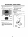
TRANSAXLE
SHIFTER LINKAGE
JUSTMENT (See Figs. 26 and 27)
TO REMOVE WHEEL FOR REPAIRS
AND AD-
(See Fig. 28)
The transaxte should be in neutral when the gear shift lever
is in the neutral (N) (lock gate) position. The adjustment is
preset at the factory; however, if adjustment is needed,
proceed as follows:
•
Make sure transaxle is in neutral (N).
°
Loosen two Iocknuts on tie rod.
°
Turn center rod until gearshift lever falls into neutral
lock gate on fender console_
°
Tighten locknuts securely,
•
•
Block up axle securely.
Remove axle cover, retainingringand washers to allow
wheel removal (rear wheel contains a square key - Do
not Iose),_
•
•
Repair tire and reassemble.
On rear wheels only: atign grooves in rear' wheel hub
and axle. Insert square key.
,
Replace washers and snap retaining ring securely in
axle groove.
Replace axle cover,
°
NOTE: To seal tire punctures and prevent fiat tires due to
slow leaks, tire sealant may be purchased from your local
parts dealer. Tire sealant also prevents tire dry rot and
corrosion
GEARSHIFT' LEVER
WASHERS
RETAINING
RING
FIG. 26
J
AXLE COVER
_SQUARE
KEY
(REAR WHEELONL_
CENTER ROD
FIG. 28
TO START ENGINE WITH A WEAK BATTERY
(See Fig. 29)
TIE ROD
......................
,,,,,,,,,,,,,,,,,,,
i
iiiii
TRANSAXLE
ateexplosivegases. Keepsparks, flame
and smoking materials away from batteries.
Always
wear batteries
eye protection
AUTION:
Lead-acid
generwhen around batteries.
i&
........................
tf your battery is too weak to start the engine, it should be
recharged.
If "jumper cables" are used for' emergency
starting, follow this procedure:
IMPORTANT: YOUR TRACTOR IS EQUIPPED WITH A 12
VOLT NEGATIVE GROUNDED
SYSTEM,
THE OTHER
VEHICLE
MUST ALSO BE A 12 VOLT NEGATIVE
GROUNDED SYSTEM.
DO NOT USE YOUR TRACTOR
BATTERY TO START OTHER VEH[CLES.
FIG. 27
TO ADJUST STEERING
II
WHEEL ALIGNMENT
If steering wheel crossbars are not horizontal (left to right)
when wheels are positionedstraight forward, remove steeringwheel and reassemble per instructionsin the Assembly
section of this manual
TO ATTACH JUMPER CABLES •
Connect each end of the RED cable to the POSITIVE
(+) terminal of each battery, taking care not to short
against chassis.
•
Connect one end of the BLACK cable to the NEGATIVE (-) terminal of fully charged battery_
° Connect the other' end of the BLACK cable to good
CHASSIS GROUND, away from fuel tank and battery'°
FRONT WHEEL TOE-IN/CAMBER
The front wheel toe-in and camber are not adjustable on
your'tractor. If damage has occurred to affect the front
wheel toe-in or camber, contact your nearest authorized
service center!department.
24
ViCE AN
ADJU
ENTS
,,lll,,ll,,i _1Ul i i,
INTERLOCKS
TO REMOVE CABLES, REVERSE ORDER •
BLACK cable first from chassis and then from the fully
charged battery°
•
RED cable last from both batteries:
POSITIVE TERMINAL
i. ...............................
AND RELAYS
Loose or damaged wiring may cause your tractor to run
poorly, stop running, or prevent it from starting,
°
Check wiring,. See electrical wiring diagram in the
Repair Parts section of this manual
NEGATIVE TERMINAL
TO REPLACE
FUSE
Replace with 30 amp automotive_type plug-in fuse. The
fuse holder is located behind the dash.
TO REMOVE HOOD AND GRILL ASSEMBLY
(See Fig. 30)
o
Raise hood,
°
Unsnap headlight wire connector.
o
Stand in front of tractor. Grasp hood at sides, tilttoward
engine and lift off of tractor.
•
To replace, reverse above procedures,.
CABLES
HOOD
CHARGED
BATTERY
POSITIVETERMINAL
NEGATIVETERMINAL
FIG. 29
TO REPLACE
HEADLIGHT
BULB
•
Raise hood.
°
Pull bulb holder out of the hole in the backside of the
grill
Replace bulb in holder and push bulb holder securely
back into the hole in the backside of the grill.
Close hood.
o
°
HEADLIGHT
WIRE
CONNECTOR
FIG. 30
25
SERVICE AND ADJUSTM
ENGINE
FINAL SETTING -
TO ADJUST THROTTLE
(See Fig. 31)
CONTROL
.o
CABLE
*
The throttle contro! has been preset at the factory and
adjustment should not be necessary. Check adjustment as
described below before loosening cable° tf adjustment is
necessary, proceed as follows:
•
With engine not running, move throttle control lever
from slow to choke position, Slowly move lever from
choke to fast position°
•
Check that holes"A" in governor control lever and hole
in governor' plate line-up. If holes "A"are not aligned,
loosen clamp screw and movethrottle cable until holes
are aligne& Tighten clamp screw securely°
GOVERNOR
CONTROL LEVER
Start engine and allow to warm for five minutes. Make
final adjustments with engine running and shift/motion
control lever in neutral (N) position.
Move throttle control leverto stow position. With finger,
rotate and ho[d throttle lever against idlespeed screwy
Turn idle speed screw to attain 1750 RPM
°
While still holding throttle lever' against idle speed
screw, turn idle mixture vaive in (clockwise) until engine begins to die and then turn out (counterclockwise)
until engine runs rough. Turn valve to a point midway
between those two positions, Release throttle lever,
ACCELERATION TEST •
GOVERNOR
CONTROL PLATE
Move throttle control lever from slow to fast position. If
engine hesitates or dies, turn idle mixture valve out
(counterclockwise)
1/8 turn. Repeat test and continue
to adjust, if necessary,
until engine accelerates
smoothly.
High speed stop is factory adjusted.
Do not adjust damage may result.
IMPORTANT:
NEVER TAMPER WITH THE ENGINE
GOVERNOR,
WHICH IS FACTORY SET FOR PROPER
ENGINE SPEED. OVERSPEEDING
THE ENGINE ABOVE
THE FACTORY
HIGH SPEED
SETTtNG
CAN BE
DANGEROUS., IFYOU THINKTHE
ENGINE-GOVERNED
HIGH SPEED NEEDS ADJUSTING,
CONTACT
YOUR
NEAREST
AUTHORIZED
SERVICE
CENTER/
DEPARTMENT, WHICH HAS PROPER EQUIPMENT AND
EXPERIENCE
TO
MAKE
ANY
NECESSARY
ADJUSTMENTS_
THROTTLE
LEVER
HOLES *'A"
CLAMP
SCREW
IDLE SPEED
SCREW
THROTTLE
CABLE
FIG. 31
TO ADJUST
CARBURETOR
(See Fig. 32)
The carburetor has been preset at the factory and adjustment should not be necessary. However, minor adjustment may be required tocompensate for differences infuel,
temperature, altitude or load. if the carburetor does need
adjustment, proceed as follows:
In general, turning idle mixture valve in (clockwise) decreases the supply offuel tothe engine givinga leaner rue!/
air mixture. Turning the idle mixture valve out (counterclockwise)increases the supply of fuel to the engine giving
a richer fuel!air mixture_
IMPORTANT: DAMAGE TO THE NEEDLE VALVE AND
THE SEAT IN CARBURETOR MAY RESULT IF SCREW IS
TURNED IN TOO TIGHT.
IDLE MIXTURE
VALVE
PRELIMINARY SETTING •
Air cleaner assembly must be assembled to the carburetor when making carburetor adjustments_
•
Be sure the throttle control cable is adjusted propedy
(see above),
o
With engine off turn idle mixture valve in (clockwise)
closing it finger tight and then turn out (counterclock_
wise) 1 full tum.
FIG. 32
o6
ENGINE
Immediately prepare your tractor for storage at the end of
the season or if the tractor will not be used for 30 days or
more_
FUEL SYSTEM
,srl_lll,
IMPORTANT:
IT IS IMPORTANT
TO PREVENT GUM
DEPOSITS
FROM FORMING
IN ESSENTIAL
FUEL
SYSTEM PARTS SUCH AS CARBURETOR,
FUEL FILTER,
FUEL HOSE, OR TANK DURING STORAGE.
ALSO,
EXPERIENCE
INDICATES
THAT ALCOHOL
BLENDED
FUELS (CALLED GASOHOL OR USING ETHANOL OR
METHANOL) CAN ATTRACT MOISTURE WHICH LEADS
TO SEPARATION AND FORMATION
OF ACIDS DURING
STORAGE.
ACIDIC GAS CAN DAMAGE THE FUEL
SYSTEM OF AN ENGINE WHILE IN STORAGE°
gasoline in the tank inside a building
where
fumesNever
may store
reachthe
an tractor
open flame
CAUTION:
with
or spark. Allow the engine to cool
before storing in any enclosure.
,
i!!11 i!rrl
I
TRACTOR
Remove mower from tractor for winter storage, When
mower is to be stored for a period of time, ctean it thoroughly, remove all dirt, grease, leaves, etc. Store in a
clean, dry area.
•
Clean entire tractor (See"CLEANING" in the Customer
Responsibilities section of this manual).
°
°
-
.
Fulty charge the battery for storage°
•
°
Start the engine and let it run until the fuel lines and
carburetor are empty.
Neveruse engineorcarburetorcleanerproductsin
the
fuel tank or permanent damage may occur.
Use fresh fuel next season.
NOTE: Fuel stabilizer is an acceptable alternative in
minimizing the formation of fuel gum deposits during storage, Add stabilizer to gasoline in fuet tank or storage
container. Always foltow the mix ratio found on stabilizer
container. Run engine at least 10 minutes after adding
stabilizer to allow the stabilizer to reach the carburetor, Do
not drain the gas tank and carburetor if using fuel stabilizer.
ENGINE OIL
Drain oil (with engine warm) and replace with clean engine
oil. (See "ENGINE" in the Customer Responsibilities
section of this manual).
BATTERY
After a period of time in storage, battery may require
recharging_
To help prevent corrosion and power leakage during
long periods of storage, battery cables should be
disconnected and battery cleaned thoroughly(see'_FO
CLEAN BATTERY AND TERMINALS" in the Customer Responsibilities section of this manual).
After cleaning, leave cables disconnected and place
cables where they cannot come in contactwith battery
terminals.
o
°
Be sure that all nuts, bolts and screws are securely
fastened° Inspect moving parts for damage, breakage
and wear. Replace if necessary.
Touch up all rusted or chipped paint surfaces; sand
lightlybefore painting_
.
Drain the fuei tank,
°
Inspect and replace belts, if necessary (See belt replacement instructions in the Service and Adjustments
section of this manual).
Lubricate as shown in the Customer Responsibilities
section of this manual
°
°
CYLINDERS
o
°
Remove spark plug(s)o
Pour one ounce of oil through spark plug hole(s) into
cylinder(s)_
°
Turn ignition key to"START" position for a few seconds
to distribute oil
•
Replace with new spark plug(s).
OTHER
°
Be sure battery drain tube is securely attached°
°
Do not store gasoline from one season to another,
•
If battery is removed from tractor for storage, do not
store battery directly on concrete or damp surfaces.
°
Replace your gasoline can if your can starts to rust.
Rust and/or dirt in your gasoline will cause problems.
•
if possible, store your tractor indoors and cover it to
give protection from dust and dirt,
°
Cover your tractor with a suitable protective cover that
does not retain moisture. Do not use plastic. Plastic
cannot breathe which allows condensation to form and
will cause your tractor to rust.
IMPORTANT: NEVER COVER TRACTOR WHFLEENGINE
AND
27
EXHAUST
AREAS
ARE
STILL
WARM,
TROUBLESHOOTING
iiimll
CORRECTION
PROBLEM
CAUSE
Wtl! not start
1.
2.
3
4,
5,
6.
7
Outoffuet+
Engine not "CHOKED" properly+
Englne flooded
Bad spark plug,.
Dirty air tilter,
Dirty fuel fi[tet
Water in fuef
8
9,
Loose or damaged widng
Carburetor out of adjustment
10.
Hard to start
........................
POINTS
...............
, ,
Engine valves out of adjustment.
1_
2,
3
4
5
6
7,
Dirty air filter+
Bad spark plug.
Weak or dead battery.
Dirty fuel fitter+
Stale or dirty fuel.
Loose or damaged wiring
Carburetor out of adjustment
8+
Engine valves out of adjustment+
Clean/replace air filter.
Replace spark plug
Recharge or replace battery,
Replace fuel filter:.
Drain fuel tank and refill with fresh gasoline,
Check all widng,
See "To Adjust Carburetor" in Service Adjustments
section.
B+ Contact an authorized sergce center/department.
t. Clutch!brake pedal not depressed
2
Attachment clutch tt engaged.
3
Weak or dead battery+
4+ Blown fuse,
5. Corroded battery terminals
6+ Loose or damaged wiring,
7+ Fautty ignition switch,
8+ Faulty solenoid or starter
9. Fautty operator presence switch(as).
..................
Engine clicks but will not
start
,,,
1+
2
3
4
5+
6,
7
8
9.
Depress clutch/brake pedal.
Disengage attachment clutch
Recharge or replace battery,
Replace fuse,
Clean battery terminals,
Check air wiring
Check/replace ignition switch.
Check/replace solenoid or starter,
Contact an authorized service centeddepartment.
, ,,, ,,,,,,
t.
2.
3,
4.
Weak or dead battery+
Corroded battery terminals,
Loose or damaged widng.
Faulty solenoid or starter.
1,
2
3
Recharge or replace battery
Ctean battery termtnais,
Check all wiring
4.
Check/replace
1,
2.
3.
4,
5.
6+
7.
8,
9,
Cutting too much grassttoo fast.
Throttte in "CHOKE" position.
Build*up of grass, leaves end trash under mower.
Dirty air filter+
Low oil level/dirty oil
Faulty spark plug,
Dirty fuel filter,
Stale or dirt,] fuel
Water in fuel+
1.
2
3
4,
5
6
7.
8
9,
Set in"Higher cur posifientreduce speed
Adjust throttle control
Clean underside of mower housing,.
Clean/replace air filter
Check oi_leveVchange oK
Clean and regap or change spark plug.
Replace fuel filter,
Drain fuel tank and refifl with fresh gasoline.
Drain fuel tank and carburetor, refilFtank with fresh
10,
11,
12,,
13,
14.
15,
10,
11,
12
13
14,
Spark plug wire loose,
Ditty engine air screen!fins
Dtrtytclogged muffler,+
Loose or damaged wiring
Carburetor out of adjustment
15,
Engine valves out of adjustment
.........
Excessive vibration
1
2,
3,
4,
5+
6
7,
,,,,,,,,,,,
Engine will not turn over
Loss of power
1_ FlUfuel tank
2. See "TO START ENGINE" in Operation section,
3, Wait several minutes before attempting to start,
4, Replace spark plug.
5,, Clean/replace air filter_
6
Replace fuei filter
7
Drain fuel tank and carburetor, refi!l tank with fresh
gasoline and replace fuel filter
8, Check all wiring.
9
See "To Adjust Carburetor" in Service Adjustments
section.
10. Contact an authorized service centeddepartment.
,,, ,,,,,,,,,,,
1.
2.
3
28
gasoElne and replace fuel filter,
Connect and tighten spark plug wire.
Clean engine air screen/fins
Cleankeplace muffler,
Check all wiring.
See "To Adjust Carburetor" in Service Adjustments
section.
Contact an authorized service centerldepartment,
ii
i i i j ii iiii
1+ Worn, bent or loose btade+
2
Bent blade mandrel.
3
Looseldamaged part(s).,
soleno!d or starter., .................
Replace blade+ Tighten blade bott
Replace blade mandrel.
Tighten loose part(s) RepFace damaged parts
TROUBLESHOOTING
PROBLEM
CAUSE
POnNTS
CORRECTION
Engine continues to run
when operator leaves seat
with attachment clutch
engaged
I
Faulty operator-safety presence control system
1,
Check wiring, switches and connections
If not
corrected, contact an authorized service canted
department
Poor cut - uneven
1,
2,
3o
4,
5.
Worn, bent or loose b_ade
Mower deck not level,
Bulldup of grass, leaves, and trash under mower.
Bent blade mandrel,
Clogged mower deck vent holes from buifdup of
grass, leaves, and trash around mandrels,
1
2.
3
4,
5_
Replace blade. Tighten bfade bolt
Level mower deck,
Clean underside of mower housing,
Replace blade mandrel
Clean around mandrels to open vent ho_es,
1
2.
3
4
Remove
Replace
Replace
Replace
ii
Mower blades will not
rotate
Poor grass discharge
!
i
I,
Obstruction In clutch mechanism.
2,
3.
4.
Worn/damaged mower drive belt
Frozen idler pulley
Frozen blade mandrel.
t.
2,
3
4,
Engine speed too slow.
Travel speed too fast
Wet grass_
Mower deck not level,
5.
6,,
7,
8
Low/uneven tire air pressure°
Worn, bent or loose blade.,
Buildup of grass, leaves and trash under mower_
Mower drive belt worn
9.
10,
1I_
Blades improperly _nstailed.
improper blades used,
Clogged mower deck vent holes from buildup of
grass, leaves, and trash around mandrels.
1,
2.
3.
4.
5,
6,
7_
8_
9.
t0.,
1t.
obstnJction
mower drive belt,
idler pulley,
blade mandrel
Ptace throttle control in "FAST" position,
Shift to slower speed.
Allow grass to dry before mowing
Level mower deck.
Check tires for proper air pressure,
Replacefsharpen blade Tighten blade bolt,
Clean underside o! mower housing
Replace mower drive belt,
Reinstall blades sharp edge down,
Replace with blades listed In this manual,
Clean around mandrels to open vent holes,
Headlight(s)not working
(if so equipped)
1.
2o
3,
4,
5.
Switch Is "OFF",
BuIb(s) burned out.
Faulty Eightswitch.
Loose or damaged widng,
Blown fuse..
1,
Turn switch "ON"
2,
3
4,
5o
Replace bulb(s).
Check/replace light switch,
Check w_ring and connections,
Replace fuse,
Battery will not charge
t,
2_
Bad battery cell(s),.
Poor cable connections,
3_
4.
Faulty regulator (if so equtpped)_
Faulty alternator.
t,,
2.
3.
4,
Replacebattery,,
Check/cleanall connections,
Replaceregulator,
RepEaceaitemator_
1.
Engine throttle control not set at "SLOW"
position for 30 seconds before stopping engine
1.
Move throttle control to "SLOW" posit}on and allow
to idle tot 30 seconds before stopping engine
,lllllll
Engine "backfires"
when turning engine
"OFF"
29
iiil,ii i
iii
i
, , i
30
TRACTOR - - MODEL NUMBER 917.258473
SCHEMATIC
oi11o
1tl-
B oK
BATTERY
RED
I
RED
T
FUSE 3OAMP.
AMMETER
(OPTIONAL)
STARTER
BLACK
WHITE
SOLENOID
RE___E.__O
_
J
CLUTCH/ BRAKE
{PEDALUP)
WHITE
SEAT SWITCH
(NOT OCCUPIED)
IGNITION
SWITCH
i
I
I
WHITE
_
_.,..(,__1
t_
BLACK
IGNITION
L
I
I
FUELSHUT-OFF
SOLENOID
UNIT
5 AMP AO
RUNtLIGHT
RUN
START
CIRCUIT
G+M+L
"MAKE"
NONE
B+L
A+Y
B+L
NONE
B+L+S
NONE
" ' -=
GROUNDING
CONNECTOR
j
D
_P
D
SPARK
PLUG
GAP
(2 PLUGS ON
TWIN CYL
DIODE
i ALTERNATOR
@ 3660 RPM
\
oFF
I BLACK
BLUE
I
UGH11NG SYSTEM OUTPUT
POSITION
I-
26 VOLTS AC MIN. @ 3660 RPM
(CHARGING SYSTEM DISCONNECTED)
CHARGING
SYSTEM OUTPUT
3 AMP DC O 3660 RPM
ORANGE
IGNITION SWITCH
!
'I
LINE =I
_'/_\
I
I
7
O
_UEL=
I
1
I
F_...r BLACK i
METER
HOUR
(OPTIONAL)
BLACK
BLUE
_
-
NT C
(CLUTCHOFF)
r
"L___
t
1
_
t
| ....
I
J
t4 VOLTS AO MIN, @ 3600 RPM (UGHTS OFF)
NOTE
YOUR TRACTOR IS
EQUIPPED WITH A SPECIAL
ALTERNATOR SYSTEM,.
BROWN
THE LIGHTS ARE NOT
CONNECTED TO THE
BATTERY, BUT HAVE THEIR
OWN ELECTRICAL SOURCE,
HEADLIGHTS
BECAUSE OF THIS, THE
BRIGHTNESS OF THE LIGHTS
WILL CHANGE WITH ENGINE
SPEED. AT IDLE THE LIGHTS
---O--WILL DIM. AS THE ENGINE tS
NON-REMOVABLE
REMOVABLE
SPEEDED UP, THE LIGHTS
CONNECTIONS
CONNECTIONS
WILL BECOME THEIR BRIGHTEST..
WIRING INSULATED CLIPS
NOTE: IF WIRING INSULATED CLIPS WERE REMOVED FOR
SERVICING OF UNIT, THEY SHOULD BE REPLACED TO
PROPERLY SECURE YOUR WIRING.
31
REPAIR PARTS
TRACTOR - - MODEL NUMBER 917.258473
\
I
\t
26
1
/
l
I
l
|
\
I
I
I
I
!
I
29
32
REPAIR PARTS
TRACTOR -- MODEL NUMBER 917.258473
ELECTRICAL
KEY
NO,
PART
NO.
1
2
3
4
6
7
8
9
15
16
19
20
21
22
24
25
26
28
29
3O
31
32
33
40
41
42
43
44
45
52
7O
144925
74760412
STD551025
STD551125
STD541025
109238X
156417
109596X
'147688
153664
STD55! 125
73350400
136850
4152J
4799J
146!47
108824X
4207J
121305X
140301
124211X
14'1226
109310X
156442
71110408
13'1563
145673
73640400
121433X
141940
140422
DESCRIPTION
Battery 12 VOLT 25 AMP
Bolt Hex Hd t/4-20unc x 3/4
Washer 9/32 x 5/8 x 16 Ga
Washer Lock Hvy Helical 1/4
Nut Fin Hex !/4-20 Unc
Tube Plastic 12"
Case Battery
Clamp Hose Olive
Fastener Snap-tn
Switch, Interlock Push-In
Washer Lock 1/4
Nut Jam Hex 1/4-20 Unc
Harness Asm Light W/4152j
Buib Light #1 t56
Cable Battery 6 Ga 11" red
Cable Battery 6 Ga w/I6 wire red
Fuse 30 AMP Auto Green
Cable Ground 6 Ga 12" black
Switch Plunger Nc Gray
Switch Ign 4 Pos
Nut Ignition
Cover Sw Key Bik I 25 Text SLT
Key ign Molded Craftsman
Harness tgn Man CI Am Hm 97
Bolt Blk. Fin Hex 1/4-20 Unc x 1/2
Cover Termina{ Red
Solenoid
Nut Keps Blk Hex 1/4-20 Unc
Ammeter Rectangular 6 Amp
Protection Wire Loop
Harness Engine B&S 14 OHV
NOTE: All component dimensions give in U.S_ inches
1 inch = 25.4 mm
33
REPAIR PARTS
TRACTOR
- - MODEL
NUMBER
917.258473
CHASSIS AND ENCLOSURES
3O
24
5
26
26
25
16
14
29
19
28
26
14 _...._
4..._.._
13
"_
145
33
10
Q
26
3
14
34
REPAIR PARTS
TRACTOR - - MODEL NUMBER 917.258473
CHASSIS
AND ENCLOSURES
KEY
NO.
PART
NO.
1
2
3
4
5
6
7
8
9
10
11
13
14
15
16
17
18
19
21
22
24
25
26
27
28
29
30
31
33
34
35
38
39
71
100
140
145
147
--
159530
140356
17490612
STD551025
155272
155923
126842X
155138
156275X0t0
STD533710
155927
155934X010
17490608
74180512
STD541431
154988X574
126938X
17521312
122933X
124479X
STD523710
19131312
STD541437
17O3O814
'140137
124029X
140001X574
136619
145244X574
145243X574
STD533707
139886
139887
73680400
I05037X
158418
156524
74760412
5479J
DESCRIPTION
Chassis Weldment
Drawbar Stretch
Screw Thdrol 3/8-16 x 3/4 Ty-tt
Washer !3/32 x 3/4 x 16 Ga,
Bumper Hood/Dash
Saddle LT Fiat Fender Shift
Shield Ht Hood Kohl/Dia Engine
Clip Retainer Slide On
Dash Silkscreened 1-Pc MoW/Amm
Bolt Carriage 3/8-!6 x 1
Panel Pnt Dash Lh
Panel Slkscr Dash Rh Weldment
Screw Thdrol 318_16x 1/2 Ty*tt
Screw Mach Trhd 5/16-18uncx3/4
Nut Keps 5/16-18 Unc
Hood Asm Pnt Weld MS-574
Bumper Hood
Screw Sltd Hex Hd w/Pl Washer
Rivet Ratchet Nylon
Washer Nylon BIk 28 x 75 x 19
Bolt Fin Hex 3/8-16unc x 1
Washer 13/32 x 13/32 x 12 Ga
Nut Lock 3/B-16 Unc
Screw Lock Spider #8 x 7/8
Grille Black Ms-428
Lens Headlight Bar Clear
Fender Pnt
Bracket Pnt Fender
Footrest Pnt Lh Lt/Y't!Gt 574
Footrest Pnt Rh Lt!Yt/Gt 574
Bolt Rdhd Sht Sqnk 3/8-16 X3/4
Bracket, Asm. Pivot, Loll., Mower Rear
Bracket, Asm. Pivot, R.H., Mower Rear
Nut Crowniock 1/4-20unc
Strip Foam 18"
Bracket, Suspension Front 7 Ga.
Rod Pivot Chassis/Hood
Bolt Hex Hd 1/4-20unc x 3/4
Plug Button Blk 359 Dia
NOTE: AUcomponent dimensionsgiven in U 3o inches
1 inch = 25.4 mm
35
REPAIR PARTS
TRACTOR
- - MODEL
NUMBER
917.258473
DRIVE
57
58
21
87
18
121
5
42-,...,.
51
)i
40
5
118
18
85
27
42-...
i
39 _..
6
32
52
6
62
35
37
36
34
61
i
26
1
27
36
48
26
51
REPAIR PARTS
TRACTOR - - MODEL NUMBER 917.258473
DRIVE
KEY
NO.
2
3
4
5
6
8
10
11
t2
13
14
t5
18
19
21
22
24
25
26
27
28
29
30
31
32
34
35
36
37
38
39
4O
41
42
47
48
49
PART
NO.
146682
123666X
12000028
12 ! 520X
17490512
141 O03
76020416
t05701X
19151216
74550412
STD551125
74490544
7478O616
STD541437
106933X
130804
STD541237
106888X
STD551037
STD561210
145204
124236X
130807
127275X
STD 523107
155071
120183X
STD551 O62
STD571810
123674X
STD523727
4-470J
•154777
19131312
127783
154604
123205X
DESCRIPTION
Transaxle, (See Breakdown) Dana,
Model 4360-113
Spring, Extension, Brake
Pulley, Transaxle
Ring, Retainer
Strap, Torque
Screw, Thd, Roll. 5/16-18 x 3/4
Rod, Shift
Pin, Cotter
Washer, Shift Plate
Washer 15/32 x 3/4 x 't6 Ga.
Bolt 1/4_28 UNF Grade 8 W/Patch
Washer
Bolt Hex Flghd 5/16 - 18 Gr. 5
Bolt Fin Hex 3/8-16unc x I Gr. 5
Nut Lock Hex W/Ins 3/8-16 UNC
Knob
Rod, Brake
Nut
Spring, Brake Rod
Washer
Pin
Rod, Parking Brake
Cap, Parking Brake, Red
Bracket, Transaxle
Keeper, Belt, L°H.
Bolt
Shaft Assembly, Foot Pedal
Bearing, Nylon
Washer
Rol! Pin
Pu}ley, Idler, Flat
Bolt
Spacer, Split .395 x °59
Keeper, Belt, Idler
Washer 13/32 x 13/16 x 12 Gauge
Pulley, Idler, V-Groove, Plastic
Bellcrank Assembly
Retainer, Belt
KEY
NO,
PART
NO.
50
51
52
53
55
56
57
58
59
6I
62
63
64
65
66
70
72
74
75
76
77
78
80
81
82
83
84
85
86
87
88
89
9O
116
118
121
STD5237t5
STD541437
STD541431
t05710X
105709X
STD523712
13O801
127274X
t40312
17490612
8883R
14O186
71170764
STD551143
154778
134683
19132012
109502X
121749X
STD581075
123583X
t21748X
131488
156043
123782X
19171216
132182
150360
71208
19212016
12000008
139964
124346X
7211O610
154774
154419
NOTE:
37
DESCRIPTION
Belt
Nut
Nut, Crownlock 5/16-18 UNC
Link, Clutch
Spring, Clutch Return
Bolt, Fin Hex 3/8-16 x 1-1/4
V-Belt, Ground Drive
Keeper, Belt, R.H.
Keeper, Belt, Center Span
Screw, Thd., Roll 3/8-16 x 3/4
Cover, Pedal
Pulley, Engine
Bolt, Hex 7/16-20 x 4 Gr_ 5
Washer
Keeper, Belt, Engine
Guide, Mower Drive Belt, R.H,
Washer 13/32 x 1-1/4 x 12 Gauge
Spacer, Axle
Washer 25/32 x 1-i/4 x 16 Gauge
E-Ring
ey, Square 2.0 x .1845/.1865
Washer 25/32 x t-5/8 x 16 Gauge
Arm, Shift
Shaft Assembly
Spring, Torsion
Washer 17/32 x 3/4 x 16 Gauge
Tie Rod
Nut, Lock Center 1/4 - 28 FNTHD
Bushing, Pivot
Washer
E-Ring
Console, Shift, 6 Speed, N/Ignition
Nut, Self-Threading, Washer Hd 1/4
Bolt Rdhd Sq Neck 3/8-16 x 1 25
Spacer Bellcrank
Nyliner Clutching STL
All component dimensions given in U.So inches
1 inch = 25°4 mm
REPAIR PARTS
STEERING
ASSEMBLY
TRACTOR
- - MODEL
NUMBER
917.258473
/
-'7_-'_38
(fo_
_...,._
!__b,
t
3_----_._3
62
f
67
/
j
32
43
28
10
3O
38
REPAIR PARTS
TRACTOR
STEERING
-- MODEL
NUMBER
917.258473
ASSEMBLY
KEY
NO,
PART
NO.
1
2
3
4
5
6
7
8
9
10
•1t
13
15
17
18
19
20
22
23
25
26
27
28
29
3O
32
36
37
38
39
40
41
42
43
46
47
53
62
65
66
67
68
69
70
139768
154427
156483
157473
6266H
121748X
19272016
12000029
3366R
156438
STD551137
'154779
739O1OOO
156545
57O79
124035X
126684X
712O0410
127501
1544O6
126847X
136874
19131416
17490812
STD561210
130465
155099
152927
139769
19133808
STD541537
104820X
124417X
121749X
121232X
6855M
73680600
156593
154780
154404
74781044
154429
160367
74780636
DESCRIPTION
Wheel Steering Std Black
Axle Asm Stamped Drooped Stl
Spindle Asm Lh
Spindle Asm Rh
Bearing Race Thrust Harden
Washer 25/32 x I 5/8 x 16 Ga
Washer 27132 x 1 1/4 x 16 Ga
Ring Klip #t5304-75
Bearing Cot Strg Bik
Link Drag Extended Stamped
Washer Lock Hvy Hlcl Spr 3/8
Bearing Axle STLT/GT
Locknut Flange 518-11 Unc
Shaft Asm Strg 5/8 x 15 19 Lt
Washer Thrust 515 x 750 x 033
Support Shaft
Washer Shim 1/4 x 5/8 x 062
Screw Hex Socket 1-4-20 x 5/8
Shaft Asm Pittman
Bracket Steering
Bushing Rod Tie BIk Lt
Gear Sector
Washer 13/32 x 7/8 x 16ga
Screw Thdrol 3/8-16x3/4 Ty-tt
Pin Cotter 1/8 x 3/4 Cad
Rod Tie Wire Form I9 75 Mech
Bushing Strg 5/8 Id Dash
Screw TT #10-32 5 3/8 Flange
Insert Cap Strg Wheel Std Blk
Washer 13132 x 2-3/8 x 8 Ga
Nut Lock Center 3/8-24unf
Adaptor Wheel Strg 640/635id
Boot Shaft Steering
Washer 25/32 x I 1/4 x 16 Ga
Cap Spindle Fr Top BIk
Fitting Grease
Nut Crowntock 3/8-16unc
Kit Steering Assembly
Spacer Axle
Bearing Arm Pittman
Bolt Fin Hex 5/8-1 lunc x 2-3/4
Brace Axle
Spacer Brace Axle
Belt Fin Hex 3/8-16unc x 2-1/4
NOTE: Al! component dimensions given in UoS. inches
1 inch = 25.4 mm
39
REPAIR PARTS
TRACTOR -- MODEL NUMBER 917.258473
SEAT ASSEMBLY
14
'!1
10
5
J
1
KEY
NO.
PART
NO,
1
2
3
4
5
6
7
8
9
10
12
13
140122
140551
STD523710
19131610
145006
£,TD541437
124181X
1749O616
19131614
155925
121246X
121248X
DESCRIP_ON
Seat 3350 Blkiblk Craftsman
Bracket Pnt Pivot Seat (blk)
Bolt Fin Hex 3/8-16unc X 1
Washer 13/32 X 3/4 X 10 Ga
Clip Push In Hinged :
Nut H_.x Lnck w/Ins 3/8-16 Unc
Spring Seat Cprsn 2 250 Blk Zi
Screw Thdrol 3/8-16 X 1 Ty-tt
Washer 13/32 X 1 X 14 Ga
Pan Pnt Seat (blk)
Bracket Pnt Mounting Switch
Bushing Snap Bik Nyl 50 Id
KEY
NO.
PART
NO.
14
15
16
17
21
22
23
24
25
26
72050412
134300
121250X
123976X
153236
STD541431
74780814
19171912
127018X
STD551150
DESCRIPTION
Bolt Rdhd Sht Nk 1/4-20x1-1/2
Spacer Split 28 X 96 Zinc
Spring Cprsn 1 27 BIk Pnt
Nut Lock 1/4 Lge Fig Gr 5 Zinc
Bolt Shoulder 5/16-18 Unc-2A
Nut Hex Lock w/Ins 5/16-18
Bolt Fin Hex 1/2-13 X 7/8 Gr 5
Washer 17/32 X 1-3/16 X 12 Ga
Bolt Shoulder 5/16-18 X 62
Washer Lock HW Hlcl Spr 1/2
NOTE: All component dimensions given in UoS_inches.
1 inch = 25_4 mm
40
REPAIR PARTS
TRACTOR - - MODEL NUMBER 917.258473
DECALS
14
9
17
3
7
21
5
7
4
14
16
tl
13
10
15
KEY
NO.
1
3
4
5
6
7
9
10
11
12
13
14
PART
NO.
156834
160304
160305
150680
133644
151799
128314
149516
156439
4900J
146046
150678
KEY
NO.
DESCRIPTION
Decal,
Decal,
Decal,
Decal,
Decal,
Decal,
Decal,
Decal,
Decal,
Decal,
Decal,
Decal,
15
16
17
18
21
Instruction Operat Eng
Hood Slope Rh Craftsman
Hood Slope Lh Craftsman
Grille Craftsman Sip LT Dov
Maint Customer Sears Dom
Panel Side
Fender Craftsman White
Btry DngdPsn Eng
Fender Danger Sears FJS
Clutch/brake Eng
V-belt Dr Sch Tractor
Chassis 42" 6sp
4,10
11
PART
NO.
160396
14O837
150333
156787
131265
138311
145246
145247
161083
161O84
KEY
NO.
PART
NO.
1
2
3
4
5
6
7
8
9
10
!1
_-
59192
65139
106222X
599O4
I06732X427
278H
9040H
106108)(427
106268X
7152J
104757X
*144334
DESCRIPTION
Decal, Mower Drive Schematic
Decal, Saddle Brake Parking
Decal, Cap Cnsmr Help Line Srs.
Decal, Mower EZ3 Mulching Sears
Decal, Lightbox
Decal, Lift Handle
Pad, Footrest Rbr Sq Generic 95
Fastner Pop In Footrest
Manual, Owner s (English)
Manual, Owner's (Spanish)
DESCRIPTION
Cap Value Tire
Stem Value
Tire F Ts t5 X 6 0 - 6 Service
Tube inner Front #35060
Rim Asm 6"front White Service
Fitting Grease
Bearing Flange
Rim Asm 8"rear White Service
Tire R Ts 18x9 5_8 Service
Tube Rear 9 5 X 8 Service
Cap Axle Blk i 50 X 1 00
Sealant, Tire (10 oz. tube)
NOTE: All component dimensions given in UoSoinches.
1 inch = 25.4 mm
41
REPAIR PARTS
TRACTOR - - MODEL NUMBER 917.258473
ENGINE
7
81
4
I
78
i__
44
38
78
33
37
y¢ ....
,%..
23
29
\
OPTIONAL
EQUIPMENT
Spark Arrester
42
REPAIR PARTS
TRACTOR
-- MODEL
NUMBER
917.258473
ENGINE
KEY
NO.
PART
NO.
1
2
3
132759
17720410
4
13
14
15
16
23
29
31
32
33
35
37
38
137352
272293
13280324
132O0300
STD551237
156123
137180
109202X
123549X
123487)(
17490512
137040
......
40
44
46
62
72
78
81
124028X
17490412
19091416
STD551131
71O70512
17490620
128861
NOTE:
DESCRIPTION
Control Throt Rh Blk Pd115 t0
Screw Hex Thd Cut 1!4-20x5/8 T
Engine (See Breakdown) B&S Model
28N707-0173-01
Muffler Exhaust B&S Lt
Gasket I 313 ld Tin Plated
Nipple Pipe 3/8 Npt X 3"
Elbow Std 90 Degree 3/8d 8 Npt
Washer Lock Ext Tooth 3/8
Shield Browning
Arrestor Spark
Tank Fuel I 25 Fr
Cap Asm Fuel Wlsym Vented
Clamp Hose BIk
Screw, Thdrol 5/16-18 x 3!4 Tyt
Line Fuel 20"
Plug Oil Drain (Order From Engine
Manufacturer)
Bushing Snap NyI BIk Fuel Line
Screw Hexwsh Thdrol 1/4-20x3/4
Washer 9/32 X 7/8 X 16ga
Washer Lock Hvy Hlcl Spr 5/16
Screw Hexhd Cap 5116-18x3/4
Screw Thdrol 3/8-16xl -1/4 Tytt
Nut Flange 1/4-20 Starter Nut
All component dimensions given in U,Soinches
1 inch = 25.4 mm
43
REPAIR PARTS
TRACTOR -- MODEL NUMBER 917.258473
LIFT
13
6
11
5
13
19
2O
13
1
32
15
161718
2O
19
15
13 _---0_
32
44
20
REPAIR PARTS
TRACTOR
-- MODEL
NUMBER
917.258473
LIFT
KEY
NO.
1
2
3
4
5
6
7
8
11
t2
13
15
16
17
18
19
20
31
32
PART
NO.
159460
159474
105767X
12000002
19211621
120183X
125631X
122365X
139865
139866
STD624008
127218
73350600
130171
73800800
139868
STD624008
140302
73540600
NOTE:
DESCRIPTION
Washer Asm Inner Spring W/
Plunger
Shaft Asm. Lift
Pin Groove
E Ring #5133-62
Washer 21/32 x I x 21 Ga_
Bearing Nylong
Grip Handle Fluted
Button Plunger Read
Link Asm Lift LH,,
Link Asm Lift Roll.
Retainer Spring
Link Front
Nut Jam Hex 112-13 Unc
Trunnion BIk Zinc
Nut Lock W!VVsh 1/2-13 Unc
Arm Suspension Mower
Retainer Spring
Bearing, Pvt. Lift. Spherical
Nut Crownlock 3/8-24
Ali component dimensions given in UoSoinches
1 inch = 25,_4mm
45
REPAIR PARTS
TRACTOR
- - MODEL
NUMBER
917.258473
MOWER
76
77
68
""4O
36
-_-132
79
46
52
34
33
103
105
•
31
17
21
22
\
2
16
28
29
,18
18
46
27
REPAIR PARTS
TRACTOR
- - MODEL
NUMBER
917.258473
MOWER
KEY
NO.
PART
NO.
1
2
3
4
5
6
8
9
10
11
'12
13
144393
STD533107
138017
138440
STD624008
130832
850857
STD551137
140296
134149
129895
137645
14
15
16
17
18
t9
20
21
22
23
24
25
26
27
28
29
30
31
32
33
34
35
36
37
40
41
43
44
45
46
48
128774
t10485X
140329
7211O610
72140505
132827
136888
STD541431
134753
131267
105304X
123713X
110452X
130968
19111016
131491
157722
129963
153535
137266
STD533717
133835
131494
STD55t037
STD541437
133551
140083
140088
STD624003
137729
133944
DESCRIPTION
Mower Housing
Bolt
Bracket Assembly,Sway Bar, Front
Bracket Assembly, Sway Bar
Retainer Spring
Arm, Suspension, Rear
Bolt, Hex 3/8-24 x 1.25 Grade 8
Washer, Lock
Washer, Hardened
Blade, Mulching
Bearing, Ball
Shaft Assembly, Mandrel, Vented
(Includes Key Number 6)
Housing, Mandrel, Vented
Bearing, Ball, Mandrel
Stripper, Vented Mower Deck
Bolt, Carriage 3/8-16 x 2-1/4
Bolt, Carriage 5/16-18 x 5/8
Bolt, Shoulder
Baffle, Vortex
Nut, Crownlock 5/!6-18 UNC
Stiffener Bracket
Bracket, Deflector
Cap, Sleeve
Spring, Torsion, Deflector
Nut, Push
Shield, Deflector
Washer 11/32 x 5/8 x 16 Gauge
Rod, Hinge
Screw Thdrol Rolling Washer Head
Washer, Spacer
Pulley, Mandrel
Nut, Toplock, Flanged
Bolt
Fastner, Christmas Tree
Pulley, Idler, Flat
Washer 13/32 x 13/16 x !6 Ga.
Nut, Crownlock 3/8-16 UNC
Rod, Pivot, with Nibs
Rod, Clutch, Secondary, with Nibs
Guard, Mandrel, Loll.
Retainer
Screw, Thd. Roll 1/4-20 x 5/8
Washer, Hardened
KEY
NO.
PART
NO.
49
50
51
52
53
54
55
56
58
59
67
68
71
72
73
74
75
76
77
78
79
80
81
82
83
84
85
92
101
102
103
104
105
106
128
132
--
155066
13134O
STD541410
139888
131845X900
133943
155O46
122052X
140086
141043
149846
144200
142427
131870
127847
121748X
120O0029
1289O3
127845
154810
127498
153701
73350600
142O28
120958X
156084
72140618
STD541437
136420
71161010
19O61216
10O71OO0
160793
2029J
153390
19132203
130794
--
145411
DESCRIPTION
Roller Assembly, Cam Follower
Bolt, Shoulder #10-24 Grade 5
Locknut
Bolt, Shoulder 5/16-18 UNC
Arm Assembly, Pad, Brake
Washer, Hardened
Arm, Idler
Spacer, Retainer
Spring, Torsion Brakes 42"
Guard, Tuv Idler (94)
Knob Custom Oval
V-Belt
Rod, Clutch, Primary, with Nibs
Spring, Return
Arm, Clutch, Secondary
Washer 25/32 x 1_5/8 x 16 Gauge
Ring, Klip
Bolt, Shoulder 3/84 6 UNC x 1o44
Keeper, Spring
Arm, Clutch, Primary
Bushing, Large, Brass
Spring, Mower Clutch
Nut, Hex Jam 3/8-16 UNC
Trunnion Adj_94
Washer Sintered
Keeper Belt Idler
Bolt Carriage 3/8q6 x 2-1/4
Locknut, Hex W/Wsh 3/8-16 UNC
Cover Mulching 42" Biack
Screw Truss Head Phil 10-24 x 5/8
Washer #10
Washer Lock #10
Latch Asm Bagger
Nut Weld
Washer Felt
Washer 13/32 x t-3/8 x 3 Ga.
Mandrel Assembly (includes Key
Numbers 840, 12-15, 31 and 32)
Mower Deck, Complete (Std deck order separately mulcher plate
components key nos. t01-106)
NOTE: All component dimensions given in UoS, inches
1 inch = 25°4 ram.
47
REPAIR PARTS
TRACTOR -- MODEL NUMBER 917.258473
DANA TRANSAXLE-
MODEL NUMBER
4360-113
20
21
22
8
24
31
32
27
10
11.
36
53
42
45
47
48
49
6t
7O
48
REPAIIR PARTS
TRACTOR-DANA TRANSAXLE
KEY PART
NO. NO,
1
2
3
4
5
6
7
8
9
10
11
12
13
14
15
t6
17
18
19
20
21
22
23
24
25
26
27
28
29
3O
31
32
33
34
35
36
37
38
39
160939
2274J
134400
105904X
160940
138235
108727X
"148266
148269
2225J
134793
148268
120415X
142674
138234
110078X
105909X
105910X
'160942
160943
148267
138236
73810500
142676
2244J
105916X
120470X
110070X
142677
142681
124644X
108980X
120406X
134796
t05925X
2228J
223tj
160944
124639X
MODEL
NUMBER
917.258473
- MODEL NUMBER 4360-113
KEY PART
NO, NO.
DESCRIPTION
Housing, Upper
Screw, Tapping, 1/4-20 X .734
Ball, Detent
Spring, Detent
Screw, Tapping, No. 10-24 X .482
Assy, Shifter
V-Ring
Bearing, Flange
Seal, Oil
Ring, Retaining
* Assy, Kit, Shim, .625 Shaft
Bearing, Flange
Washer, Plain, .632 X 1.38 X .046
Key, Woodruff, No. 9
Assy, Kit, Input Shaft
Pinion, Bevel, 14T
Ring, Retaining
Chain, 24 Pitches
Cover, Detent
Gear, Spur, 12T
Collar, ChJtch
Assy, Kit, Clutch Keys
Nut, Lock, 5/16-24
Shaft, Intermediate
Key, Woodruff, Noo61
Ring, Retaining
Sprocket, 18T
Spacer, 1.131 X I_45 X A94
Gear, Spur, 37T
Gear, Spur, 35T
Gear, Spur, 30T
Gear, Spur, 25T
Gear, Spur, 22"1"
Gear, Spur I9T
Washer, Plain, .640 X 1.37 X _061
Washer, Plain, .632 X 1o00 X .046
Washer, Plain, °632 X 1.00 X .031
Assy, Gear, Comb., 12T & 30T
Shaft, Idler
40 120472X
4!
105928X
42 110084X
43 134394
44 120473X
45 142678
46 143697
47 124641X
48 106589X
49 120408X
50 105937X
51 2226J
52 134401
53 2264J
54 160946
55 110081X
56 160948
57 t10071X
58 t20952X
59 110082X
60 160950
61 142680
62 120961X
63 7294J
64 108989X
65 160952
66 120954X
67 160953
68 138244
69 108996X
70 160954
71 120951X
72 120416X
DESCRIPTION
Spacer, .633 X .87 X .755
Sprocket, 9T
Gear, Bevel, 42T
* Assy, Kit, Shim, .750 Shaft
Shaft, Drive
Gear, Spur, 12T
Gear, Spur, 15T
Gear, Spur, 20T
Gear, Spur, 25T
Gear, Spur, 28T
Gear, Spur, 31T
Washer, Plain, _632 X 1.00 X .060
Washer, Neoprene
Washer, Plain, o758X 1.25X .031
Axle, LH
Gear, Miter, 15T
Ring, Retaining
Gear, Spur, 32T
Shaft, Cross
Gear, Miter, 15T
Axle, RH
Housing, Lower
Puck, Friction
Disc, Brake
Spacer, Brake Puck
Jaw, Brake
Pin, Dowel
Screw, Tapping, 5/16-18 X 2.35
Lever, Actuating
Washer, P_atn, o321 X 1o00 X .055
Bracket, Anti-Rotation
Puck, Friction
Grease
NOTE: All component dimensions given in U.So inches
1 inch = 25.4 mm
49
REPAIR PARTS
TRACTOR
BRIGGS
& STRATTON
ENGINE
- - MODEL
- MODEL
NUMBER
NUMBER
28N707,
917.258473
TYPE
NUMBER
0173-01
230
_614
230
9
@_
634A
ao7
635
337
"JrREQUIRES SPECIAL TOOLS
TO INSTALL. SEE REPAIR
INSTRUCTION MANUAL
40
7
1022
4O
868
166
_13
022
45
305
1029
294_
i,ii,,,ii!
.......
_102_6
1023
5O
REPAIR PARTS
TRACTOR - - MODEL NUMBER 917,258473
BRIGGS
......
1'27
& STRATTON
138
106-987
ENGINE
- MODEL
95
634
117
NUMBER
28N707,
TYPE
NUMBER
0173-01
634B
_, 1022
i_
5
_
137
142
104
147
1033 VALV E OVERHAUL
i
121 CARBURETOR
.............
iiH
_
OVERHAUL
I
KIT
IlL
I
L
I1
KIT
iii1111111 I1
i i ii ii ilJli,
iii
27c-_
@
15
13i
.......
' ...................... o
___
REQUIRES SPECIAL TOOLS
TO INSTALL. SEE REPAIR
INSTRUCTION MANUAL.
_
611
ii
ii
51
.
127
!
]
125
REPAIR PARTS
TRACTOR - - MODEL NUMBER 917.258473
BRIGGS
& STRATTON
ENGINE
3
523
- MODEL
20
634A
NUMBER
842
28N707,
524
868
TYPE
NUMBER
868A
0173-01
467
284A
171
_9
2
..........................
358
GASKET
SET
445
363
_524
_i
I
O
I
138
137
SET
_77CARBUR_OR
GAS,
KET
224
668
I
304
305_
535
468
455
1006
52
334
REPAIR PARTS
TRACTOR
BRIGGS & STRATTON
- - MODEL
NUMBER
917,258473
ENGINE - MODEL NUMBER 28N707, TYPE NUMBER
0173-01
i
601
209
783
801
1090
311
8O3
544
53
REPAIR PARTS
TRACTOR -.. MODEL NUMBER 917,258473
BRIGGS & STRATTON
KEY PART
NO. NO.
1
2
3
5
7
8
9
10
tl
12
13
15
16
18
20
22
23
24
25
26
27
28
29
496412
399265
391086
495858
272614
495735
27803
94621
281246
271916
271997
271996
94728
94239
495162
94196
494238
291675
94624
492326
222698
49586O
495977
495978
495979
495854
495852
495851
495855
260924
299691
391286
494504
495490
32
32A
33
34
35
37
40
45
46
51
94695
94648
495856
495857
262811
224502
224641
262411
496884
272465
52
272569
53
75
78
94637
224061
94832
ENGINE - MODEL NUMBER 28N707, TYPE NUMBER
KEY PART
NO, NO.
DESCRIPTION
Cylinder Assembly
Bearing, Cylinder
* Seal, Oil
Head, Cytinder
*** Gasket, Cylinder' Head
Breather Assembly
* Gasket, Valve Cover
Screw, Sems
Tube, Breather
* Gasket, Crankcase Cover, ..015"
* Gasket, Crankcase Cover, .005"
* Gasket, Crankcase Cover, .009"
Screw, Cylinder Head
Plug, Oil Drain
Crankshaft
Timing Gear Key
Base, Engine
* Seal, Oil
Screw, Seres, Base Mounting
Flywheel and Ring Gear' Assembly,
Magneto
Key, Flywheel
Piston Assembly, Standard Size
Piston Assembly, .010" Oversize
Piston Assembly, ..020"Oversize
Piston Assembly, .030" Oversize
Ring Set, Piston, Standard Size
Ring Set, Piston, .010" Oversize
Ring Set, Piston, .020" Oversize
Ring Set, Piston, ,030" Oversize
Lock, Piston Pin
Pin Assy.., Piston, Standard Size
Pin Assy., Piston, .005" Oversize
Rod Assembly, Connecting
Rod Assembly, Connecting,
.020" Undersize Crankpin Bore
Screw, Hex Washer Head, 1-57/64
Screw, Hex Washer Head, 1-5/8
Valve, Exhaust
Valve, Intake
Spring, Valve
Guard, Flywheel
Retainer, Valve Spring
Tappet, Valve
Gear, Cam
**** Gasket, Carburetor (Carburetor to
Elbow) (Also Included in Gasket
Set, Part Number 495993)
*** Gasket, Carburetor
Elbow to Cylinder)
'
ud, Carburetor Mounting
Washer, Spring
Screw, Pan Head
95
98
104
105
106
108
117
118
121
123
125
127
130
131
133
137
138
141
142
147
164
166
171
187
188
192
201
209
216
2t9
222
224
225
227
230
232
238
240
265
284
*
**
94098
495800
231789
231855
231854
22454O
231858
495932
498116
94616
498051
224539
494379
494381
281165
281164
495931
231859
497472
214047
94555
281051
393815
94627
492160
262767
260695
262766
490815
495611
94729
495157
493935
94742
262785
262836
394358
221535
94704
0173-01
DESCRIPTION
** Screw, Throttle
Screw, Idle Speed
** Pin, Float Hinge
** Valve Float
** Seat, Inlet Valve
Valve, Choke
** Jet, Needle Valve
Valve, Needle
Carburetor Overhaul Kit
Screw, Elbow Mounting
Carburetor Assembly
** Plug, Welch (Sold in Kit Only)
Valve, Throttle
Shaft and Lever, Throttle
Float, Carburetor
**** Gasket, Float Bowl
**** Washer, Bowl
Shaft and Lever; Choke
** Nozzle, Carburetor
** Pilot, Jet
Elbow, Carburetor
Stud, Rocker Arm
Nut, Air Cleaner Mounting
Line, Fuel (11" Long, Cut to Suit)
Screw, Seres
Screw Assembly, Rocker Arm
Link, Governor
Spring, Governor
Link, Choke
Gear, Governor'
Plate, Governor Control
Screw, Sems, Air Cleaner
Crank, Governor
Lever Assembly, Governor
Washer, Govemor Crank
Spring, Governor Link
Cap, Valve
Filter, Fuel (In Fuel Line)
Clamp, Casing
Screw, Hex Head
Included in Gasket Set (495993)
Included in Carburetor Kit (497535)
***
Included in both Gasket Set (495993) and
Valve Overhaul Kit (495992)
****
Included in Gasket Set (495993), Carburetor' Kit
(497535) and Carburetor Gasket Set (494385)
NOTE: All component dimensions given in U.S inches
1 inch = 25_4 mm
54
REPAIR PARTS
TRACTOR
BRIGGS & STRATTON
KEY PART
NO. NO.
284A 94073
294 810068
304 496280
305 94786
306 225020
307 94386
309 497595
3'10 497602
311 497608
333 495859
334 93381
337 491055
346 93705
356 497708
358 495993
363 19203
383 89838
423 94073
445 493909
455 222561
467 493903
468 494439
474 393474
482 93621
510 497606
523 495230
524 68838
525 4961!3
535 272403
537 281106
544 497603
552 231597
562 92613
592 231082
60! 93053
611 493496
614 93306
618 262803
634 281168
634A 491323
634B 281167
635 280872
646 224546
657 93496
663 94620
668 280848
718 230192
726 392134
727 490324
728 94627
729 281390
-- MODEL
NUMBER
917,258473
ENGINE - MODEL NUMBER 28N707, TYPE NUMBER
KEY PART
NO. NO.
DESCRIPTION
Screw, Hex Head
Screw, Set
Housing, Blower
Screw, Hex, Head,
Blower Housing Mounting
Shield, Cylinder
Screw, Cylinder Shield
Motor, Starter
Bott, Thru
Brush Set
Armature, Magneto
Screw, Seres, Armature Mounting
Plug, Spark
Screw, Hex Head
Wire Assembly
Gasket Set
Puller, Flywheel
Wrench, Spark Plug
Screw, Sems
Cartridge, Air Cleaner
Cup, Screen Mounting
Knob, Air Cleaner
Screen, Flush Rotating
Stator, Alternator
Screw, Sems
Drive, Starter
Cap and Dipstick, Oil Filler
* Seal, FillerTube
Tube, Oil Filler
Element, Filter
* O-Ring, Air Cleaner
Armature. Starter
Bushing, Governor Crank
Bolt, Carriage
Nut, Hex
Clamp, Fuel Pipe
Elbow, Fuel Pipe
Pin, Cotter
Spring, Choke Return
** Seal, Choke Shaft
* Seal, Governor
** Washer, Throttle Shaft
Boot, Spark Plug
Brace, Air Cleaner
Screw, Sems
Screw, Self-Tapping
Spacer
Pin, Dowel
Gear, Ring
[Includes Mountinq Hardware)
Cover, Starter
Screw, Hex Head
Clip, Wire
729A
741
757
758
759
761
783
801
802
803
842
847
85t
868
868A
871
872
875
877
947
965
975
977
987
t005
1006
1019
1022
1023
1026
225170
262932
213998
399891
298909
94593
280104
394856
497605
497604
270920
496415
224110
494435
272610
262835
281361
495862
393456
497157
94010
495933
494385
281166
281400
224413
496758
272475
224552
494432
495I36
1029 224554
1033 495992
1034 495248
1044 94673
1054 270723
1058 272623
t090 497607
RPM Settings:
*
**
0173-01
DESCRIPTION
Retainer, Wire
Gear. Timing
Link, Counterweight
Counterweight Assembly
Pin, Counterweight
Screw, Counterweight
Gear, Starter
Cap, Drive
Cap, End
. Housing, Starter
Seal, Oil Filler Cap
Fill Group, Oil
Terminal, Ignition Cable
*** Seal Assembly, Valve
*** Gasket, Valve
Bushing, Guide (Intake & Exhaust)
Cover, Air Cleaner
Body, Air Cleaner
Diode and Connector Assembly
Solenoid
Nut, Hex
Bowl Assembly, Carburetor
Carburetor Gasket Set
** Seal. Throttle Shaft
Fan, Flywheel
Retainer, Fan
Label Kit
*** Gasket, Cover
Cover, Rocker Arm
Rod, Push, Intake
Rod, Push, Exhaust
Arm, Rocker
Valve Overhaul Kit
Guide Assembly, Push Rod
Screw, Hex Head
Tie, Cable
Manual, Owner's
Retainer, Brush
Low: 1650-1850,
High: 3200-3400
Included in Gasket Set (495993)
included in Carburetor Kit (497535)
***
Included in both Gasket Set (495993) and
Valve Overhaul Kit (495992)
....
included in Gasket Set (495993), Carburetor Kit
(497535) and Carburetor Gasket Set (494385)
NOTE: All component dimensions given in US. inches
1 inch = 25_4 mm
55
E
56
ViCE NOTES
57
IJILIii
iiiiiii
iii,i,i
NOTES
SEI
LI
/
58
LI
UIIIIIII
lJllll{lll
II:IIII
I
SUGGESTED GUIDE FOR SIGHTING SLOPES FOR SAFE OPERATION
ONLY RIDE UP AND DOWN HILL,
NOT ACROSS HILL
SIGHTING
GUIDE
"'......CUT
TH'_
SIGHT AND HOLD THIS LEVEL WITH
SKY LINE OR TREE.
15 ° MAX.
£RAFTIMAN ®
OWNER'S
MANUAL
MODEL NO.
917.258473
15.5 HP IC
ELECTRIC START
42" MOWER
6 SPEED TRANSAXLE
LAWN TRACTOR
Each tractor has its own model number,
its own model number'.,
Each engine has
The modet number for your tractor witt be found on the
model plate located under the seat.
The model number for your engine will be found on the
blower housing of the engine_
All parts listed herein may be ordered from any Sears,
Roebuck and Co. Service Center/Department and most Retai{ Stores,
IF YOU NEED
REPAIR SERVICE
OR PARTS:
FOR REPAIR SERVICE, CALL
THIS TOLL FREE NUMBER:
1-800-4-REPAIR
(1-800-473-7247)
FOR REPLACEMENT PARTS
INFORMATION AND
ORDERING, CALL THIS
TOLL FREE NUMBER:
1-800-FON-PART
(1-800-366-7278)
WHEN ORDERING REPAIR PARTS, ALWAYS GIVE THE
FOLLOWING INFORMATION:
- PRODUCT - TRACTOR
° MODEL NUMBER - 917.258473
,, ENGINE MODEL NO, - 28N707, TYPE NO. 0173-01
• PART NUMBER
• PART DESCRIPTION
Your Sears merchandise has added value when you
consider Sears has service units nationwide staffed with
Sears trained technicians .... professional technicians
specifically trained to insure that we meet our pledge to
you, we service what we sell.
FOR CONSUMER ASSISTANCE
HOT LINE, CALL THIS
TOLL FREE NUMBER:
1-800-659-5917
161083
II
6_12.97
JH
Pdnted in UoS.A,,
I IIIIIIII
II IIIlUUlIIIIIIIIIIIIII
IIIIII
IIIIII
IIIIII
III
IIIIIIIII
Hil