1
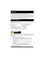
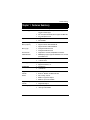
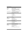
GS-SR195V 1U Rack Mount Server System Installation Guide Intel® Pentium Xeon Processor Serverboard Rev. 1.1 GS-SR195V Rack Mount Server Table of Content Safety, Care and Regulatory Information ................................................ 4 Introduction .............................................................................................. 8 Contents Packages ................................................................................ 8 WARNING! ............................................................................................... 8 Chapter 1 Features Summary ................................................................. 9 Chapter 2 System Hardware Installation ............................................... 12 Step 2-1: Chassis Removal and Installation ................................................................ 12 Step 2-2: CPU Installation ............................................................................................... 13 Step 2-3: Heat Sink Installation ....................................................................................... 14 Step 2-4: Memory Installation ........................................................................................ 14 Step 2-5: PCI-X Expansion Card Installation ................................................................ 15 Step 2-6: Hard Disk Drive Installation ............................................................................ 16 Step 2-7: FAN Duct Removal and Installation .............................................................. 16 Step 2-8: ZCR Installation and Removal (Optional Device) ....................................... 17 Chapter 3 Appearance of GS-SR195V ................................................. 18 3-1: Front View of GS-SR195V ...................................................................................... 18 3-2: Rear View of GS-SR195V ...................................................................................... 19 3-3: Switch and LED Indicators Introduction ................................................................. 20 3-4: LAN LED Description ............................................................................................... 21 3-5 : Connector Icon Description ................................................................................... 22 Chapter 4 Motherboard Layout & Jumper Setting ................................ 23 4-1: GA-9IVDPC Motherboard Layout ........................................................................... 23 4-2: DDR DIMM Slot Population ..................................................................................... 25 4-3: Jumper Setting ......................................................................................................... 26 2 Table of Content Chapter 5 BIOS Setup .......................................................................... 28 Main ........................................................................................................... 30 Advanced ................................................................................................... 33 PCI Configuration ............................................................................................................. 34 Advanced Chipset Control ............................................................................................. 36 Advanced Processor Option .......................................................................................... 39 Peripheral Configuration .................................................................................................. 41 Hardware Monitor ............................................................................................................ 45 Security ...................................................................................................... 46 Server ......................................................................................................... 48 Console Redirection ........................................................................................................ 48 Boot ............................................................................................................ 51 Exit ............................................................................................................. 52 Chapter 6 Appendix .............................................................................. 55 6-1: Acronyms ................................................................................................................. 55 3 GS-SR195V Rack Mount Server Safety, Care and Regulatory Information Important safety information Read and follow all instructions marked on the product and in the documentation before you operate your system. Retain all safety and operating instructions for future use. * The product should be operated only from the type of power source indicated on the rating label. * If your computer has a voltage selector switch, make sure that the switch is in the proper position for your area. The voltage selector switch is set at the factory to the correct voltage. * The plug-socket combination must be accessible at all times because it serves as the main disconnecting device. * All product shipped with a three-wire electrical grounding-type plug only fits into a grounding-type power outlet. This is a safety feature. The equipment grounding should be in accordance with local and national electrical codes. The equipment operates safely when it is used in accordance with its marked electrical ratings and product usage instructions * Do not use this product near water or a heat source. * Set up the product on a stable work surface or so as to ensure stability of the system. * Openings in the case are provided for ventilation. Do not block or cover these openings. Make sure you provide adequate space around the system for ventilation when you set up your work area. Never insert objects of any kind into the ventilation openings. * To avoid electrical shock, always unplug all power cables and modem cables from the wall outlets before removing covers. * Allow the product to cool before removing covers or touching internal components. Precaution for Product with Laser Devices Observe the following precautions for laser devices: * Do not open the CD-ROM drive, make adjustments, or perform procedures on a laser device other than those specified in the product's documentation. * Only authorized service technicians should repair laser devices. Precaution for Product with Modems, Telecommunications, ot Local Area Network Options Observe the following guidelines when working with options: * Do not connect or use a modem or telephone during a lightning storm. There may be a risk of electrical shock from lightning. 4 Safety Information * To reduce the risk of fire, use only No. 26 AWG or larger telecommunications line cord. * Do not plug a modem or telephone cable into the network interface controller (NIC) receptacle. * Disconnect the modem cable before opening a product enclosure, touching or installing internal components, or touching an uninsulated modem cable or jack. * Do not use a telephone line to report a gas leak while you are in the vicinity of the leak. Federal Communications Commission (FCC) Statement Note: This equipment has been tested and found to comply with the limits for a Class B digital device, pursuant to Part 15 of the FCC Rules. These limits are designed to provide reasonable protection against harmful interference when the equipment is operated in a commercial environment. This equipment generates, uses, and can radiate radio frequency energy and, if not installed and used in accordance with the instruction manual, may cause harmful interference to radio communications. Operation of this equipment in a residential area is likely to cause harmful interference in which case the user will be required to correct the interference at his own expense. Properly shielded and grounded cables and connectors must be used in order to meet FCC emission limits. Neither the provider nor the manufacturer are responsible for any radio or television interference caused by using other than recommended cables and connectors or by unauthorized changes or modifications to this equipment. Unauthorized changes or modifications could void the user's authority to operate the equipment. This device complies with Part 15 of the FCC Rules. Operation is subject to the following two conditions: (1) this device may not cause harmful interference, and (2) this device must accept any interference received, including interference that may cause undesired operation. FCC part 68 (applicable to products fitted with USA modems) The modem complies with Part 68 of the FCC Rules. On this equipment is a label that contains, among other information, the FCC registration number and Ringer Equivalence Number (REN) for this equipment. You must, upon request, provide this information to your telephone company. If your telephone equipment causes harm to the telephone network, the Telephone Company may discontinue your service temporarily. If possible, they will notify in advance. But, if advance notice is not practical, you will be notified as soon as possible. You will be informed of your right to file a complaint with the FCC. 5 GS-SR195V Rack Mount Server Your telephone company may make changes in its facilities, equipment, operations, or procedures that could affect proper operation of your equipment. If they do, you will be notified in advance to give you an opportunity to maintain uninterrupted telephone service. The FCC prohibits this equipment to be connected to party lines or coin-telephone service. The FCC also requires the transmitter of a FAX transmission be properly identified (per FCC Rules Part 68, Sec. 68.381 (c) (3)). / for Canadian users only / Canadian Department of Communications Compliance Statement This digital apparatus does not exceed the Class B limits for radio noise emissions from digital apparatus as set out in the radio interference regulations of Industry Canada. Le present appareil numerique n'emet pas de bruits radioelectriques depassant les limites applicables aux appareils numeriques de Classe B prescrites dans le reglement sur le brouillage radioelectrique edicte par Industrie Canada. DOC notice (for products fitted with an Industry Canada-compliant modem) The Canadian Department of Communications label identifies certified equipment. This certification means that the equipment meets certain telecommunications network protective, operational and safety requirements. The Department does not guarantee the equipment will operate to the user satisfaction. Before installing this equipment, users ensure that it is permissible to be connected to the facilities of the local Telecommunications Company. The equipment must also be installed using an acceptable method of connection. The customer should be aware that compliance with the above conditions might not prevent degradation of service in some situations. Repairs to certified equipment should be made by an authorized Canadian maintenance facility designated by the supplier. Any repairs or alterations made by the user to this equipment, or equipment malfunctions, may give the telecommunications company cause to request the user to disconnect the equipment. Users should ensure for their own protection that the electrical ground connections of the power utility, telephone lines and internal metallic water pipe system, if resent are connected together. This precaution may be particularly important in rural areas. Caution: Users should not attempt to make such connections themselves, but should contact the appropriate electric inspection authority, or electrician, as appropriate. 6 Safety Information NOTICE: The Load Number (LN) assigned to each terminal device denotes the percentage of the total load to be connected to a telephone loop which is used by the device, to prevent overloading. The termination on a loop may consist of any combination of devices subject only to the requirement that the sum of the Load Numbers of all the devices does not exceed 100. / for European users only / CAUTION Danger of explosion if battery is incorrectly replaced. Replace only with the same or equivalent type recommended by the manufacturer. Dispose of used batteries according to the manufacturer’s instructions. 7 GS-SR195V Rack Mount Server Introduction Welcome to Gigabyte GS-SR195V Rack mount Server System Installation Guide. The guide provides instructions for configuration hardware for the GS-SR195V your system. This installation guide will assist you in installing all the essential components for the sever system. For your protection, please read and undertand all of the safety and operating instructions regarding your Gigabyte Server and retain for future reference. The procedures in this guidebook assusme that your are a system or network administrator experienced in installing similar hardware. Contents Packages When opening the package, please ensure the system components are not damaged during the shipping. Using the following checklist to verify the contents. If any component is missing or damaged in the system, please contact your vendor immediately. ; Chassis ; GA-9IVDPC Motherboard (Installed) ; Power Supply (Installed) ; GC-REIU (PCI-E Riser Card) ; FAN Duct x 1 ; Silm type CD-ROM drive (Installed) ; ; CPU Heat Sink x 2 Cables (RJ45) ; GS-SR195V System Installation Guide ; Driver CD for motherboard driver & utility ; ; Case Handle Kit x 2 COM2 Cable x 1 WARNING! Computer motherboards and expansion cards contain very delicate Integrated Circuit (IC) chips. To protect them against damage from static electricity, you should follow some precautions whenever you work on your computer. 1. Unplug your computer when working on the inside. 2. Use a grounded wrist strap before handling computer components. If you do not have one, touch both of your hands to a safely grounded object or to a metal object, such as 3. the power supply case. Hold components by the edges and try not touch the IC chips, leads or connectors, or 4. other components. Place components on a grounded antistatic pad or on the bag that came with the 5. components whenever the components are separated from the system. Ensure that the ATX power supply is switched off before you plug in or remove the ATX power connector on the motherboard. 8 Feature Summary Chapter 1 Features Summary Motherboard GA-9IVDPC Processor Supported Dual socket 604 for Intel® Xeon(Nocona/Irwindale) processor suopprts 3.6 GB and upper Intel® Xeon (Nocona/Irwindale) CPUs supports 800 MHz FSB 2nd cache depend on CPU Chipset Intel® E7320 Chipset Intel® 6300ESB System Memory: Memory Capacity Supports maximum 32GB with DDR 266 Memory Type Supports maximum 16GB with DDR333 8 x Registered DDR 266 scoket Error Correction: 6 x Registered DDR 333 scoket Single-bit Errors Correction, Multiple Bit Errors Detection Additional Features DIMM Sparing support, support for RASUM fail-over to an on-line spare DIMM device Expansion Slot 1 riser card supports 1 x PCI-X 64/66MHz add-on card 1 x PCI-E x8 slot RAID Supported Adaptec® 7901X Supports Host RAID 0,1,10 Cooling Fans: 4 X CPU Fans 1 X Power Fan Integrated LANs: Controller Features Broadcom® BCM5721 and BCM 5705 GbE WOL, Teaming, ALB, AFT BCM5721 supports PCI-Express BCM5705 suports PCI 32/33MHz Integrated Graphics: Controller Mass Storage System Integrated ATI Rage XL 4 x Hot Swapable SCSIHDDs 1 Slim Type 24X CD-ROM 9 GS-SR195V Rack Mount Server SCSI Controller: Controller Adaptec AIC- 7901X chipset RAID Supported Features Supports Host RAID RAID 0, 1 and 10 data protection Mirroring supports automatic background rebuilds Features LBA and Extended Interrupt 13 drive translation in controller onboard BIOS ZCR Supported (Optional) Front Panel One SO-DIMM I/F on board support for ZCR card extension Optional Adaptec ASR2015S& ASR2025S ZCR Supports Hardware RAID 0,1,5,10,50, JBOO Power SW, Reset SW, NMI SW, UID SW, 2 x LAN LED 1 x Power/Sleep LED 1 x HDD LED 1 x System Status LED 2 x USB Super I/O Controller Additional Features ITE IT8712F-IX Supports Wake on Ring Hardware Monitor CPU/System Fan Revolution detect CPU/System temperature detect Built-in I/O System Voltage Detect 2 x Serial ports (COM, 1 at rear and 1 at front) 1 x USB 2.0 dual-port connector 1 x VGA connector 2 x RJ45 LAN ports P/S 2 Keyboard and Mouse Connectors System BIOS: BIOS Type Special Features Lincensed Phoenix on 8Mb Flash RAM Supports multi boot function User setting for hardware monitoring Supports PXE ACPI 1.0 Compliant/ ACPI defined S1, S4, and S5 10 GS-SR195V Rack Mount Server Server Management Functions: BMC Chip Failure Detection NS IPMI 1.5 controller IPMI 1.5 specification of Server management Event Logging Remote Management 32KB Nonvolatile Memory to Log System Failure Events Follow the IPMI 1.5 specification of Server management Environment Ambient Temperature Operating Temperature: 5oC to 35oC Relative Humidity Non-operating Temperature: 0oC to 50oC 10-80% operating Humidity at 30o C Safety Regulations System Dimention: FCC, CE, BSMI, CB, 19"W x 1.73"H x 19.5"D Electrical Power Supply Single Power Supply 480W Note: 1. If you want to purchase USB FDD, we suggest MITSUMI as recommended brand. 2. The extended lan port is difficult to unplug, please handle it carefully. 11 GS-SR195V Rack Mount Server Chapter 2 System Hardware Installation Please observe the safety information in chapter “Important Safety Information” Do not expose the server to extreme environmental conditions. Protect it from dust, humidity, and heat. Step 2-1: Chassis Removal and Installation Step 1 Loosen thscrew from the top cover. Step 2 Push down the indentation located at two sides of the chassis, and slide toward to remove the top cover. Step 3 Reverse Step 1, and 2 to replace the chassis cover. Step 2 Step 1 Screw Note: Before installing CPU, you must remove the FAN duct. For FAN duct removal, please see Sub-section 2-7 “FAN Duct Removal and Installtion” for detail instruction. 12 Hardware Installation Process Step 2-2: CPU Installation Please make sure the CPU type and speed that are supported by the motherboard. Step 1 Raise the locking bar on the socket. Step 2 Aligning the pins of the processor with the socket, insert the processor into the socket. Step 3 Close the handle completely and finish CPU installation. Step 1 Step 2 Pin1 indicator Step 3 13 GS-SR195V Rack Mount Server Step 2-3: Heat Sink Installation Step 1 Place the Heat Sink on the CPU. Before putting the heat sink on the CPU, please well remember to apply the thermal conductivity compound on the CPU. Step 2 Seat the heat sink with the four screws. Installation completed. Step 1 Step 2-4: Memory Installation 1. The DIMM slot has a notch, so the DIMM memory module can only fit in one direction. 2. Insert the DIMM memory module vertically into the DIMM slot. Then push it down. 3. Close the plastic clip at both edges of theDIMM slots to lock the DIMM module. 4. DIMM must be populated in order starting at the farthest slot from the MCH chipset. Each logical DIMM must be made of two identical DIMMs having the same device size on each and the same DIMM size. 5. Reverse the installation steps when you wish to remove the DIMM module. For detail DIMM Population, please refer to section 4-2: DDR DIMM Slot Population Step 2 Step 1 14 Hardware Installation Process Step 2-5: PCI Expansion Card Installation GS-SR195V provides expansion riser slot for one PCI-X 64/66MHz slot; and one with PCI-E x8 and x4 slots. To install the peripheral, please go through the following steps. Note: Before installing the PCI expansion card, please check the card size limitation. Size limitation for PCI-E is listed below: Heigth: 18.73mm(max) ; Length: 167.65mm(max) ; Width: 52mm(max) Step 1 Lift the riser bracket slightly, then pull it out from the server chassis. Step 2 Align the expansion card with the guiding groove. Slide the expansion card into the slot until the card firmly seats. Step 3 Align the riser bracket to the system module (see the arrow direction mark 1), and push it to locked position. Note!! The riser bracket must be firmtly seated into the module. (See the arrowdirection), or it will cause power connection losses. Step 4 Reverse Step 1 & 2 to lock the riser bracket firmly. Installation completed. Step 1 Step 2 Step 3 15 GS-SR195V Rack Mount Server Step 2-6: Hard Disk Drive Installation Step 1 Press the release button and pull the blank out of the drive bay. Step 2 Remove the hard disk blank. Slide hard disk into blank and secure it with screws. Step 3 Slide the drive into the cage until it clicks, locking the drive into place. Connect cable and power. Step 2 Step 1 Release button Step 2-7: FAN Duct Removal and Installation Step 1 Pull up the screw-holder and lossen the thumbscrews. Lift up to remove the fan duct. Step 2 For FAN Duct Installation, place the fan duct on the top of heat sinks. Fasten the screws to the locked position and push down the screw-holders. Step 1 16 Hardware Installation Process Step 2-8: ZCR Installation and Removal (Optional Device) Step 1 Aling a ZCR on the module such that the notch on the ZCR exactly match the notches in the module. Step 2 Push the card in untill it clicks. Then, press down the card vertically. Step 3 To remove the ZCR card, unlock the ZCR retaining clips. Step 1 Step 2 Step 3 17 GS-SR195V Rack Mount Server Chapter 3 Appearance of GS-SR195V 3-1: Front View of GS-SR195V Slim Type CD-ROM USB Connector LE D s Hot swap SCSI HDDs 18 System Appearance 3-2: Rear View of GS-SR195V PS/2 Co nne cto rs USB Co nne cto rs LAN1 Po rt (RJ45) LAN2 Po rt (RJ45) COM Po rt VGA Po rt Limite d Lo w-Pro file Rise r Slo t Full-He ig ht Rise r Slo t Po we r co rd 19 GS-SR195V Rack Mount Server 3-3: Switch and LED Indicators Introduction LAN1/2 Activities System Event LED Reset HDD NMI ID BTN&LED Power Name Color Condition Description Power Green Green On Blink Power On Sleep (S1) -Amber Off Blink Power Off (S4) System Ready but degraded, CPU Failed, Amber On DIMM Killed Critical Alarm: Critical Power Module Failure, SYS (System) Critical FANs Failure, Voltage (Power Supply) Critical Teemperature and Voltage -Green Off Blink System healthy. Hard Disk Drive Access Amber Amber On Blink HDD Fault HDD Rebuild -Green Off On No Access and No HDD Fault LAN Link / No access Activity Green -- Blink Off LAN access Idle LAN2 Activity Green Green On Blink LAN Link / No access LAN access ID -Blue Off On Idle Unti selected for identification (Identification) -- Off No identification HDD LAN1 20 LED Description 3-4: LAN LED Description Name LAN Color Green Link/Activity Green GbE LAN Yellow Speed Green - Condition ON Description LAN Link / no Access BLINK OFF LAN Access Idle ON ON 1Gbps connection 100Mbps connection OFF 10Mbps connection 21 GS-SR195V Rack Mount Server 3-5 : Connector Icon Description Suggest Icon Description Keyboard VGA Mouse LA N Serial Port USB 22 Motherboard Layout Chapter 4 Motherboard Layout & Jumper Setting 4-1: GA-9IVDPC Motherboard Layout 2 V S D E M N DDR -B3 DDR -A4 O P C 1 B T 1 7 1 7 1 7 1 23 DDR -B4 DDR -B2 DDR -B1 L G PCI-E_ 1 U C133 C11 2 K BAT 1 W EC4 C11 9 J F DDR -A2 X C11 0 COM2 H DDR -A1/11 SM1-2111 84 -10R 1 I A Q R GS-SR195V Rack Mount Server A CPU 0 M DDR A2 B C CPU1 Intel MCH E7320 N O DDR B2 DDR A3 D E ATI Rage-XL Intel 6300ESB P Q DDR B3 DDR A4 F G Broadcom® BCM5705 Broadcom® BCM 5721 R S DDR B4 IPMI Connector H I IT8712F-IX COM2 T U Adaptec AIC-7901X PCI-X_1 (64/66MHz) J K GPIO DDR A1 V W PCI-E ( x4 Lane x8 Slot ) SO-DIMM Type ZCR Extention Slot ** L DDR B1 X Battery **This device is use for Adaptec ASR-2015s and ASR-2025s ZCR population. 24 Motherboard Layout 4-2: DDR DIMM Slot Population Table 4-2-1: Supported DDR266 DIMM Populations NOTE!! For DDR-266 DIMM population, DIMM must be populated starting from the A4/B4 slots. D IMM C onfiguration D IMM1 D IMM2 D IMM3 D IMM4 1 Si ngle Rank Empty Empty Empty Si ngle Rank 1 D ual Rank Empty Empty Empty D ual Rank 2 Si ngle Rank Empty Empty Si ngle Rank Si ngle Rank 1 D ual Rank, 1 Si ngle Rank Empty Empty D ual Rank Si ngle Rank 2 D ual Rank Empty Empty D ual Rank D ual Rank 3 Si ngle Rank Empty Si ngle Rank Si ngle Rank Si ngle Rank 1 D ual Rank, 2 Si ngle Rank Empty D ual Rank Si ngle Rank Si ngle Rank 2 D ual Rank, 1 Si ngle Rank Empty D ual Rank D ual Rank Si ngle Rank 3 D ual Rank Empty D ual Rank D ual Rank D ual Rank 4 Si ngle Rank Si ngle Rank Si ngle Rank Si ngle Rank Si ngle Rank 1D ual Rank, 3 Si ngle Rank D ual Rank Si ngle Rank Si ngle Rank Si ngle Rank 2 Si ngle Rank, 2 D ual Rank D ual Rank D ual Rank Si ngle Rank Si ngle Rank 3 D ual Rank, 1 Si ngle Rank D ual Rank D ual Rank D ual Rank Si ngle Rank 4 D ual Rank D ual Rank D ual Rank D ual Rank D ual Rank Table 4-2-2: Supported DDR333 DIMM Populations NOTE!! For DDR-333 DIMM population, DIMM must be populated starting from the A3/B3 slots. A4/B4 slots cannot be applied for DDR-333 DIMM. The mainboard only supports 6 DIMMs for DDR-333. D IMM C onfiguration D IMM1 D IMM2 D IMM3 1 Si ngle Rank Empty Empty Si ngle Rank 1 D ual Rank Empty Empty D ual Rank 2 Si ngle Rank Empty Si ngle Rank Si ngle Rank 1 D ual Rank, 1 Si ngle Rank Empty D ual Rank Si ngle Rank 2 D ual Rank Empty D ual Rank D ual Rank 3 Si ngle Rank Si ngle Rank Si ngle Rank Si ngle Rank 1 D ual Rank, 2 Si ngle Rank D ual Rank Si ngle Rank Si ngle Rank 25 GS-SR195V Rack Mount Server 4-3: Jumper Setting CLR_CMOS ( (Clear CMOS Function) You may clear the CMOS data to its default values by this jumper. Default value doesn’t include the “Shunter” to prevent from improper use this jumper. To clear CMOS, temporarily short 1-2 pin. COM2 1 2 DDR -B3 DDR -A4 DDR -B4 DDR -B1 DDR -A2 C133 C11 2 C11 9 C11 0 DDR -A1/11 SM1-2111 84 -10R DDR -B2 E C 4 1 1-2 close: Clear CMOS 1 2-3 close: Normal (Default value) PCI-E_ 1 BAT 1 1 1 7 1 7 1 7 1 BIOS_TBL (CMOS Lock Function) COM2 1 2 DDR -B3 DDR -A4 C133 C11 2 DDR -B1 DDR -A2 DDR -B2 C11 9 DDR -B4 1 P CI-E_ 1 C11 0 DDR -A1/11 SM1-2111 84 -10R EC 4 BAT 1 1 1 1 7 1 7 1 7 1 26 1-2 close: Top block lock 2-3 close: Disable Top block function (Default value) Jumper Setting BIOS_WP (BIOS Werite Protect Function) COM2 1 2 PCI-E_ 1 DDR -B3 DDR -A4 DDR -B4 DDR -B1 DDR -B2 DDR -A2 C133 C11 2 C11 9 C11 0 DDR -A1/11 SM1-2111 84 -10R EC 4 BAT 1 1 1 1 1 7 1 7 1 7 1 27 1-2 close: Enable BIOS Write Protect Function 2-3 close: BIOS writable. (Default value) GS-SR195V Rack Mount Server Chapter 5 BIOS Setup BIOS Setup is an overview of the BIOS Setup Program. The program that allows users to modify the basic system configuration. This type of information is stored in battery-backed CMOS RAM so that it retains the Setup information when the power is turned off. ENTERINGSETUP Power ON the computer and press <F2> immediately will allow you to enter Setup. CONTROLKEYS <Ç> Move to previous item <È> Move to next item <Å> Move to the item in the left hand <Æ> Move to the item in the right hand <Esc> Main Menu - Quit and not save changes into CMOS Status Page Setup Menu and Option Page Setup Menu - Exit current page and return to Main Menu <+/PgUp> Increase the numeric value or make changes <-/PgDn> Decrease the numeric value or make changes <F1> General help, only for Status Page Setup Menu and Option Page Setup Menu <F2> Reserved <F3> Reserved <F4> Reserved <F6> Reserved <F7> Reserved <F8> Reserved <F9> Load the Optimized Defaults <F10> Save all the CMOS changes, only for Main Menu 28 BIOS Setup GETTINGHELP Main Menu The on-line description of the highlighted setup function is displayed at the bottom of the screen. Status Page Setup Menu / Option Page Setup Menu Press F1 to pop up a small help window that describes the appropriate keys to use and the possible selections for the highlighted item. To exit the Help Window press <Esc>. z Main This setup page includes all the items in standard compatible BIOS. z Advanced This setup page includes all the items of AMI special enhanced features. (ex: Auto detect fan and temperature status, automatically configure hard disk parameters.) z Security z Server Change, set, or disable password. It allows you to limit access the system and setup. Server additional features enabled/disabled setup menus. z Boot z Exit This setup page include all the items of first boot function features. There are five optionsin this selection: Exit Saving Changes, Exit Discarding Changes, Load Optimal Defaults, Load Failsafe Defaults, and Discard Changes. 29 GS-SR195V Rack Mount Server Main Once you enter Phoenix BIOS Setup Utility, the Main Menu (Figure 1) will appear on the screen. Use arrow keys to select among the items and press <Enter> to accept or enter the sub-menu. PhoenixBIOS Setup Utility Main Advanced Security Server System Time: [00:13:12] System Date: [01/01/2005] IDE Channel 0 Master [CD-ROM] IDE Channel 0 Slave [None] IDE Channel 2 Master [None] IDE Channel 3 Slave [None] Boot Exit Item Specific Help System Information F1: Help Esc: Exit KL: Select Item IJ: Select Menu + -: Change Values F5: Setup Defaults Enter: Select Sub-Menu F10: Save&Exit Figure 1: Main System Time The time is calculated based on the 24-hour military time clock. Set the System Time (HH:MM:SS) System Date Set the System Date. Note that the “Day” automatically changed after you set the date. (Weekend: DD: MM: YY) (YY: 1099~2099) 30 BIOS Setup IDE Channel 0 Master, Slave / Channel 1 Master, Slave, Serial ATA The category identifies the types of hard disk from drive C to F that has been installed in the computer. There are two types: auto type, and manual type. Manual type is user-definable; Auto type which will automatically detect HDD type. Note that the specifications of your drive must match with the drive table. The hard disk will not work properly if you enter improper information for this category. If you select User Type, related information will be asked to enter to the following items. Enter the information directly from the keyboard and press <Enter>. Such information should be provided in the documentation form your hard disk vendor or the system manufacturer. TYPE 1-39: Predefined types. Users: Set parameters by User. Auto: Set parameters automatically. (Default Vaules) CD-ROM: Use for ATAPI CD-ROM drives or double click [Auto] to set all HDD parameters automatically. ATAPI Removable: Removable disk drive is installed here. Multi-Sector Transfer This field displays the information of Multi-Sector Transfer Mode. Disabled: The data transfer from and to the device occurs one sector at a time. Auto: The data transfer from and to the device occurs multiple sectors at a time if the device supports it. LBA Mode This field shows if the device type in the specific IDE channel support LBA Mode. 32-Bit I/O Enable this function to max imize the IDE data transfer rate. Transfer Mode This field shows the information of Teansfer Mode. Ultra DMA Mode This filed displays the DMA mode of the device in the specific IDE channel. 31 GS-SR195V Rack Mount Server System Information This category includes the information of Processor Type, Speed, Extended memory, BIOS Version, BIOS Date, System Product Name, System serial number, System version, System UUID, Main Board ID, and Main Board Serial number. 32 BIOS Setup Advanced About This Section: Advanced With this section, allowing user to configure your system for basic operation. User can change the processor options, chipset configuration, PCI configuration and chipset control. PhoenixBIOS Setup Utility Main Advanced Security Server PCI Configuration Boot Exit Item Specific Help Advanced Chipset Control Advanced Processor Option Peripheral Configuration Hardware Monitor Reset Configuration Data [No] ClkGen Spread Spectrum [Disabled] System After AC Back [Pre-State] Extended Memory Testing [Enabled] Network Server [Enabled] Clear Case Open Log [Enter] F1: Help Esc: Exit KL: Select Item IJ: Select Menu + -: Change Values F5: Setup Defaults Enter: Select Sub-Menu F10: Save&Exit Figure 2: Advanced 33 GS-SR195V Rack Mount Server PCI Configuration PhoenixBIOS Setup Utility PCI Configuration Item Specific Help Embedded Vedio Controller Embedded SCSI Controller Embedded NIC Embedded NIC (Gbit#2) F1: Help Esc: Exit KL: Select Item IJ: Select Menu + -: Change Values F5: Setup Defaults Enter: Select Sub-Menu F10: Save&Exit Figure 2-1: PCI Configuration Embedded Video Controller Onboard VGA Control Enabled Enable onboard VGA device. (Default value) Disabled Disable this function. Embedded SCSI Controller Option ROM Scan Enabled Enableing this item to initialize device expansion ROM. (Defualt value) Disabled Disable this function. 34 BIOS Setup Embedded NIC (Gbit #1 / 2) Onboard LAN Control Enabled Enable onboard LAN 1 / 2 device. (Default value) Disabled Disable this function. Option ROM Scan Enabled Enableing this item to initialize device expansion ROM. Disabled Disable this function. (Defualt value) 35 GS-SR195V Rack Mount Server Advanced Chipset Control PhoenixBIOS Setup Utility Advanced Chipset Control Item Specific Help USB Controller [Enabled] Legacy USB Support [Disabled] Force Compliance Mode [Enabled] PCI-E port A Device 2 [Enabled] PCI-E port A1 Device 3 [Enabled] 4GB PCI Hole Granularity [128MB] Data Parity Error Recovery [Enabled] Memory Frequency [Auto] Wake On LAN [Enabled] F1: Help Esc: Exit KL: Select Item IJ: Select Menu + -: Change Values F5: Setup Defaults Enter: Select Sub-Menu F10: Save&Exit Figure 2-2: Advanced Chipset Control USB Controller This item allows users to enable or disable the USB device by setting item to the desired value. Enabled Enable USB controller. (Default value) Options Disbale this function. Legacy USB Support This option allows user to function support for legacy USB. Enabled Enables support for legacy USB. (Default Value) Disabled Disables support for legacy USB. 36 BIOS Setup Force Compliance Mode This option allows user to function PCI-E Compliance mode by setting item to desired value. Enabled Enables PCI-E Force Compliance mode. (Default Value) Disabled Disables this function. PCI-E port A Device 2 Force PCI Express v1.0 Compability Mode, this PCI-E port A by setting to desired value. Force PCI Express 1.0 Force PCI Express v1.0 Compability Mode. Enabled Enables PCI-E port A Device2 (Default Value) Disabled Disables this function. PCI-E port A1 Device 3 Force PCI Express v1.0 Compability Mode, this PCI-E port A1 by setting to desired value. Force PCI Express 1.0 Force PCI Express v1.0 Compability Mode. Enabled Enables PCI-E port A1 Device3 (Default Value) Disabled Disables this function. 4GB PCI Hole Granularity Select the granularity of PCI hole for PCI resource. If MTRRS are not enough, we may use this option to reduce the MTRR occupation. 128MB Select 128MB as granularity of PCI hole. (Default value) 256MB Select 256MB as granularity of PCI hole. Data Parity Error Recovery Enabled Enable data parity error recovery function. (Default vaules) Disabled Disable this function. 37 GS-SR195V Rack Mount Server Memory Frequency Determine the specifiy memory frequency. 266MHz Select 266MHz as memory frequecncy for system. 333MHz Select 333MHz as memory frequecncy for system. Auto Auto determine memory frequency for system. (Default values) Wake On LAN This option allow user to determine the action of the system when a LAN wake up occurs. Enabled Enable Wake On LAN. (Default value) Disabled Disable this function. Note: This item must enabled if you’re running under Windows operating system. 38 BIOS Setup Advanced Processor Option PhoenixBIOS Setup Utility Advanced Processor Option Item Specific Help Hyper Threading Technology [Enabled] Machine Cecking [Disabled] Thermal Management 2 [Disabled] Adjacent Cache Line Prefetch [Enabled] Set Max Ext CPUID = 3 [Disabled] Thermal Management 1 [Disabled] NX Protection [Enabled] F1: Help Esc: Exit KL: Select Item IJ: Select Menu + -: Change Values F5: Setup Defaults Enter: Select Sub-Menu F10: Save&Exit Figure 2-3: Advanced Processor Option Hyper Threading Technology Enabled Enables Hyper-Threading Technology Feature when using Windows XP operating systems that are optimized for Hyper-Threading technology. (Default value) Disabled Disables Hyper-Threading Technology when using other operating systems. Machine Checking Enabled EnableMachine Checking. (Default value) Disabled Disable this function. 39 GS-SR195V Rack Mount Server Thermal Managerment 2 Select between TM1 and TM2. Enabled Select Thermal Management 2 function. Disabled Disable this function. (Default value) Adjacent Cache Line Prefetch Enabled Processor will fetch both cache lines when it requires data that is not currently inits cache. (Defualt value) Disabled Processor will only fetch the cache line that contains the data currently required by the processor. Set Max Ext CPUID = 3 Set MAX CPUID extended function value to 3. Enabled Enable Set Max Ext CPUID = 3 function. Disabled Disable this function. (Default value) Thermal Managerment 1 If enabled, when the thermal sensor indicates that the die temperature is at the pre-determined threshold, the processor will reduce the bus to core ratio and operating voltage. Enabled Enable Thermal Management 1 function. (Default value) Disabled Disable this function. NX Protection This category provides user to enable virus protection avoiding unknow and spite attack. Enabled NX Protection function. (Default value) Disabled Disable this function. 40 BIOS Setup Peripheral Configuration PhoenixBIOS Setup Utility Peripheral Configuration Serial Port A Item Specific Help [Enabled] Base I/O address/IRQ Serial Port B [3F8/IRQ4] [Enabled] Base I/O address/IRQ [2F8/IRQ3] Floppy disk controller [Enabled] Floppy Check [Enabled] Parallel ATA [Both] Serial ATA [Enabled] Native Mode Operation [Auto] F1: Help Esc: Exit KL: Select Item IJ: Select Menu + -: Change Values F5: Setup Defaults Enter: Select Sub-Menu F10: Save&Exit Figure 2-4: Peripheral Configuration Serial Port A This allows users to configure serial prot A by using this option. Disabled Disable the configuration. Enabled Enable the configuration (Default value) Base I/O Address/IRQ 3F8/IRQ4 Set IO address to 3F8. (Default value) 2F8/IRQ3 Set IO address to 2F8. 3E8/IRQ4 Set IO address to 3E8. 2E8/IRQ3 Set IO address to 2E8. 41 GS-SR195V Rack Mount Server Serial Port B This allows users to configure serial prot B by using this option. Disabled Disable the configuration. Enabled Enable the configuration (Default value) Base I/O Address/IRQ 3F8/IRQ4 Set IO address to 3F8. 2F8/IRQ3 Set IO address to 2F8. (Default value) 3E8/IRQ4 Set IO address to 3E8. 2E8/IRQ3 Set IO address to 2E8. Floppy disk controller Enabled Enable the floppy disk controller. (Default value) Disabled Disable the device. Floppy Check Enabled Enable the device to verify floppy typer when system boot. Disabled Disable the this function. (Default value) Parallel ATA Disabled Both Disable the device. Select both Channel 0 and Channel 1 as Parallel ATA. (Default value) Channel 0 Select both Channel 0 as Parallel ATA. Channel1 Select both Channel 1 as Parallel ATA. 42 BIOS Setup Serial ATA Enabled Enable Serial ATA device. (Default value) Disabled Disable the Serial ATA. Native Mode Operation This option allows user to set the native mode for ATA function. Note that certain OS is not supported under Native Mode. Auto Auto detected. (Default value) Serial ATA Set Native mode to Serial ATA. Parallel ATA Set Native mode to Parallel ATA. Reset Configuration Data Yes Clear the Extended System Configuration Data (ESCD) area. No Disable this function. (default value) Clk Gen Spread Spectrum Enabled Enable ClkGen Spread Spectrum. Disabled Disabled this function. (Default value) System After AC Back Set the mode od operation if an AC/Power loss occurs. Power On Power on system without pressing power button. Stay Off Keep the power off until the power button is pressed. Pre- State Set system to the last sate when AC power is removed. Do not power on system when AC power is back. (Default value) 43 GS-SR195V Rack Mount Server Extended Memory Testing Determine which type of tests will be performed extended memory. (above 1M) Enabled Enable Extended Memory Testing. (Default value) Disabled Disable this function. Network Server Enabled System will be secured at boot to prevent tampering during network operation. (Default value) Disabled Disable this function. Clear Case Open Log Press [Enter] to clear the Case Open Log. When you press <Enter> on this item, you will get a confirmation dialog box with a message as below: Setup Confirmation Are you sure to clear the Case Open Log? [Yes] [No] 44 BIOS Setup Hardware Monitor PhoenixBIOS Setup Utility Hardware Monitor Item Specific Help CPU 1 Temperature 38C/100F CPU 2 Temperature 38C/100F System Temperature 38C/100F W83792d Temperature 1 33C/091F W83792d Temperature 2 33C/091F W83792d Temperature 3 33C/091F Voltage Monitor Fan Monitor F1: Help Esc: Exit KL: Select Item IJ: Select Menu + -: Change Values F5: Setup Defaults Enter: Select Sub-Menu F10: Save&Exit Figure 2-5: Hardware Monitor CPU 1&2/ System/ W83792d 1/2/3 Temperature Display the current CPU1/2 temperature, System, and W83792d 1/2/3 ambient temperature. Voltage: VCORE 1&2/ 3.3V/ +12V / 1.5V / 2.5V Detect system's voltage status automatically. FAN (RPM) Display the current CPUs, and Power FAN speed. 45 GS-SR195V Rack Mount Server Security PhoenixBIOS Setup Utility Main Advanced Security Server Supervisor Password Is: User Password Is: Clear Clear Set Supervisor Password [Enter] Set User Password [Enter] Password On Boot [Disabled] F1: Help Esc: Exit KL: Select Item IJ: Select Menu Boot Exit Item Specific Help + -: Change Values F5: Setup Defaults Enter: Select Sub-Menu F10: Save&Exit Figure 3: Security * About This Section: Security In this section, user can set either supervisor or user passwords, or both for different level of password securities. In addition, user also can set the virus protection for boot sector. Set Supervisor Password You can install and change this options for the setup menus. Type the password up to 6 characters in lengh and press <Enter>. The password typed now will clear any previously entered password from the CMOS memory. You will be asked to confirm the entered password. Type the password again and press <Enter>. You may also press <Esc> to abort the selection and not enter a specified password or press <Enter> key to disable this option. 46 BIOS Setup Set User Password You can only enter but do not have the right to change the options of the setup menus. When you select this function, the following message will appear at the center of the screen to assist you in creating a password. Type the password up to 6 characters in lengh and press <Enter>. The password typed now will clear any previously entered password from the CMOS memory. You will be asked to confirm the entered password. Type the password again and press <Enter>. You may also press <Esc> to abort the selection and not enter a specified password. Password on boot Password entering will be required when system on boot. Enabled Requries entering password when system on boot. Disabled Disable this function. (Default value) 47 GS-SR195V Rack Mount Server Server PhoenixBIOS Setup Utility Main Advanced Security Server Boot Console Redirection Item Specific Help Halt On [Mid] Clear Mem. ECC Error Info. [Disabled] Fatal A on port A [Enabled] F1: Help Esc: Exit Exit KL: Select Item IJ: Select Menu + -: Change Values F5: Setup Defaults Enter: Select Sub-Menu F10: Save&Exit Figure 4: Server Console Redirection PhoenixBIOS Setup Utility Console Redirection Item Specific Help Com Port Address Baud Rate [19.2K] Console Type [Direct] Flow Control [CTS/RTS] Continue C.R after POST [Off] F1: Help Esc: Exit KL: Select Item IJ: Select Menu + -: Change Values F5: Setup Defaults Enter: Select Sub-Menu F10: Save&Exit Figure 4-1: Console Redirection 48 BIOS Setup Com Port Address If this option is set to enabled, it will use a port on the motherboard. On-board COMA Use COMA as he COM port address. On-board COMB Use COMB as he COM port address. Disabled Disable this function. (Default value) Baud Rate This option allows user to set the specified baud rate. Options 300, 1200, 2400, 9600, 19.2K, 38.4K, 57.6K, 115.2K. Console Type This option allows user to select the specified console type. This is defined by IEEE. PC-ANSI is the standard PC-type terminal. Note that for VT100+, you must select English as your languuage. And VT-UTF8 uses unicode. Options vt100, vt100+, vt100 8bit, PC ANSI 7bit, PC-ANSI, VT-UTF8. Flow Control Enables Flow Control when EMP is dahring the same serial port as console redirection, the flow control must be set to CTS/RTS or CTS/RTS+CD depending on whether a modem is used. None Not supported. XON/OFF Software control. CTS/RTS Hardware control. (Default values) Continue C.R. after POST This option allows user to enable console redirection after O.S has loaded. On Enable console redirection after O.S has loaded. Off Disable this function. (Default value) 49 GS-SR195V Rack Mount Server Halt On The category determines whether the computer will stop if an error is detected during power up. NO Errors The system boot will not stop for any error that may be detected and you will be prompted. All Errors Whenever the BIOS detects a non-fatal error the system will be stopped. Mid The system boot will not stop for a keyboard or disk error; it will stop for all other errors. (Default value) Clear Mem. ECC Error Info Enabled Enable Clear memory ECC error information function. Disabled Disable this function. (Default value) Fatal Error on port A Enabled Enable Fatal Erre on port A. (Default value) Disabled Disable this function. 50 BIOS Setup Boot PhoenixBIOS Setup Utility Main Advanced Security Server Boot + CD-ROM Drive Exit Item Specific Help + Hard Drive Removable Device MBA V8.1.53 Slot 0100 MBA V8.1.53 Slot 0420 F1: Help Esc: Exit KL: Select Item IJ: Select Menu + -: Change Values F5: Setup Defaults Enter: Select Sub-Menu F10: Save&Exit Figure 5: Boot * About This Section: Boot The “Boot” menu allows user to select among four possible types of boot devices listed using the up and down arrow keys. By applying <+> and <Space> key, you can promote devices and by using the <-> key, you can demote devices. Promotion or demotion of devices alerts the priority that the system uses to search for boot device on system power on. Boot Device Priority ` Removable Device / Hard Drive / CD-ROM Drive/ These three fields determines which type of device the system attempt to boot from after PhoenixBIOS Post completed. Specifies the boot sequence from the available devices. If the first device is not a bootable device, the system will seek for next available device. 51 GS-SR195V Rack Mount Server Exit PhoenixBIOS Setup Utility Main Advanced Security Server Exit Saving Changes Boot Exit Item Specific Help Exit Discarding Changes Load Settup Default Discard Changes Save Changes F1: Help Esc: Exit KL: Select Item IJ: Select Menu + -: Change Values F5: Setup Defaults Enter: Select Sub-Menu F10: Save&Exit Figure 6: Exit * About This Section: Exit Once you have changed all of the set values in the BIOS setup, you should save your chnages and exit BIOS setup program. Select “Exit” from the menu bar, to display the following sub-menu. Exit Saving Changes Exit Discarding Changes Load Settup Default Discard Change Save Changes 52 BIOS Setup Exit Saving Changes This option allows user to exit system setup with saving the changes. Press <Enter> on this item to ask for the following confirmation message: Pressing ‘Y’ to store all the present setting values tha user made in this time into CMOS. Therefore, whenyou boot up your computer next time, the BIOS will re-configure your system according data in CMOS. Setup Confirmation Save configuration changes and exit now? [Yes] [No] Exit Discarding Changes This option allows user to exit system setup without changing any previous settings values in CMOS. The previous selection remain in effect. This will exit the Setup Utility and restart your compuetr when selecting this option. Press <Enter> on this item to ask for confirmation message. Setup Warning Configuration has hot been saved! Save before exiting [Yes] [No] Load Settup Default This option allows user to load default values for all setup items. When you press <Enter> on this item, you will get a confirmation dialog box with a message as below: Setup Confirmation Load default configuratin now? [Yes] [No] 53 GS-SR195V Rack Mount Server Discard Changes This option allows user to load previos values from CMOS for all setup item. When you press <Enter> on this item, you will get a confirmation dialog box with a message as below: Setup Confirmation Load previous configuration now? [Yes] [No] Save Changes This option allows user to save setup dat ato CMOS. When you press <Enter> on this item, you will get a confirmation dialog box with a message as below: Setup Confirmation Save configuration changes now? [Yes] [No] Press [Yes] to save setup daya to CMOS. 54 Appexdix Chapter 6 Appendix 6-1: Acronyms Acronyms ACPI Meaning Advanced Configuration and Power Interface APM AGP Advanced Power Management Accelerated Graphics Port AMR ACR Audio Modem Riser Advanced Communications Riser BBS BIOS BIOS Boot Specification Basic Input / Output System CPU CMOS Central Processing Unit Complementary Metal Oxide Semiconductor CRIMM CNR Continuity RIMM Communication and Networking Riser DMA DMI Direct Memory Access Desktop Management Interface DIMM DRM Dual Inline Memory Module Dual Retention Mechanism DRAM DDR Dynamic Random Access Memory Double Data Rate ECP ESCD Extended Capabilities Port Extended System Configuration Data ECC EMC Error Checking and Correcting Electromagnetic Compatibility EPP ESD Enhanced Parallel Port Electrostatic Discharge FDD FSB Floppy Disk Device Front Side Bus HDD IDE Hard Disk Device Integrated Dual Channel Enhanced IRQ Interrupt Request 55 GS-SR195V Rack Mount Server Acronyms Meaning I/O IOAPIC Input / Output Input Output Advanced Programmable Input Controller ISA LAN Industry Standard Architecture Local Area Network LBA LED Logical Block Addressing Light Emitting Diode MHz MIDI Megahertz Musical Instrument Digital Interface MTH MPT Memory Translator Hub Memory Protocol Translator NIC OS Network Interface Card Operating System OEM PAC Original Equipment Manufacturer PCI A.G.P. Controller POST PCI RIMM Power-On Self Test Peripheral Component Interconnect Rambus in-line Memory Module SCI SECC Special Circumstance Instructions Single Edge Contact Cartridge SRAM SMP Static Random Access Memory Symmetric Multi-Processing SMI USB System Management Interrupt Universal Serial Bus VID ZCR Voltage ID Zero Channel RAID 56