1
cr
System 5cr
System Switcher
68-388-01
Printed in the USA
Precautions
Safety Instructions • English
This symbol is intended to alert the user of important operating and maintenance
(servicing) instructions in the literature provided with the equipment.
This symbol is intended to alert the user of the presence of uninsulated dangerous
voltage within the product's enclosure that may present a risk of electric shock.
Warning
Power sources • This equipment should be operated only from the power source indicated on the
product. This equipment is intended to be used with a main power system with a grounded
(neutral) conductor. The third (grounding) pin is a safety feature, do not attempt to bypass or
disable it.
Caution
Power disconnection • To remove power from the equipment safely, remove all power cords from
the rear of the equipment, or the desktop power module (if detachable), or from the power
source receptacle (wall plug).
Read Instructions • Read and understand all safety and operating instructions before using the
equipment.
Power cord protection • Power cords should be routed so that they are not likely to be stepped on or
pinched by items placed upon or against them.
Retain Instructions • The safety instructions should be kept for future reference.
Servicing • Refer all servicing to qualified service personnel. There are no user-serviceable parts
inside. To prevent the risk of shock, do not attempt to service this equipment yourself because
opening or removing covers may expose you to dangerous voltage or other hazards.
Follow Warnings • Follow all warnings and instructions marked on the equipment or in the user
information.
Avoid Attachments • Do not use tools or attachments that are not recommended by the equipment
manufacturer because they may be hazardous.
Slots and openings • If the equipment has slots or holes in the enclosure, these are provided to
prevent overheating of sensitive components inside. These openings must never be blocked by
other objects.
Lithium battery • There is a danger of explosion if battery is incorrectly replaced. Replace it only
with the same or equivalent type recommended by the manufacturer. Dispose of used batteries
according to the manufacturer's instructions.
Consignes de Sécurité • Français
Avertissement
Ce symbole sert à avertir l’utilisateur que la documentation fournie avec le matériel
contient des instructions importantes concernant l’exploitation et la maintenance
(réparation).
Alimentations• Ne faire fonctionner ce matériel qu’avec la source d’alimentation indiquée sur
l’appareil. Ce matériel doit être utilisé avec une alimentation principale comportant un fil de
terre (neutre). Le troisième contact (de mise à la terre) constitue un dispositif de sécurité :
n’essayez pas de la contourner ni de la désactiver.
Ce symbole sert à avertir l’utilisateur de la présence dans le boîtier de l’appareil de
tensions dangereuses non isolées posant des risques d’électrocution.
Déconnexion de l’alimentation• Pour mettre le matériel hors tension sans danger, déconnectez tous
les cordons d’alimentation de l’arrière de l’appareil ou du module d’alimentation de bureau (s’il
est amovible) ou encore de la prise secteur.
Attention
Lire les instructions• Prendre connaissance de toutes les consignes de sécurité et d’exploitation avant
d’utiliser le matériel.
Conserver les instructions• Ranger les consignes de sécurité afin de pouvoir les consulter à l’avenir.
Respecter les avertissements • Observer tous les avertissements et consignes marqués sur le matériel ou
présentés dans la documentation utilisateur.
Eviter les pièces de fixation • Ne pas utiliser de pièces de fixation ni d’outils non recommandés par le
fabricant du matériel car cela risquerait de poser certains dangers.
Protection du cordon d’alimentation • Acheminer les cordons d’alimentation de manière à ce que
personne ne risque de marcher dessus et à ce qu’ils ne soient pas écrasés ou pincés par des
objets.
Réparation-maintenance • Faire exécuter toutes les interventions de réparation-maintenance par un
technicien qualifié. Aucun des éléments internes ne peut être réparé par l’utilisateur. Afin
d’éviter tout danger d’électrocution, l’utilisateur ne doit pas essayer de procéder lui-même à ces
opérations car l’ouverture ou le retrait des couvercles risquent de l’exposer à de hautes tensions
et autres dangers.
Fentes et orifices • Si le boîtier de l’appareil comporte des fentes ou des orifices, ceux-ci servent à
empêcher les composants internes sensibles de surchauffer. Ces ouvertures ne doivent jamais
être bloquées par des objets.
Lithium Batterie • Il a danger d'explosion s'll y a remplacment incorrect de la batterie. Remplacer
uniquement avec une batterie du meme type ou d'un ype equivalent recommande par le
constructeur. Mettre au reut les batteries usagees conformement aux instructions du fabricant.
Sicherheitsanleitungen • Deutsch
Vorsicht
Dieses Symbol soll den Benutzer auf wichtige Anleitungen zur Bedienung und
Wartung (Instandhaltung) in der Dokumentation hinweisen, die im Lieferumfang
dieses Gerätes enthalten ist.
Stromquellen • Dieses Gerät sollte nur über die auf dem Produkt angegebene Stromquelle betrieben
werden. Dieses Gerät wurde für eine Verwendung mit einer Hauptstromleitung mit einem
geerdeten (neutralen) Leiter konzipiert. Der dritte Stift oder Kontakt ist für einen Erdschluß, und
stellt eine Sicherheitsfunktion dar und sollte nicht umgangen oder außer Betrieb gesetzt werden.
Dieses Symbol soll den Benutzer darauf aufmerksam machen, daß im Inneren des
Gehäuses dieses Produktes gefährliche Spannungen, die nicht isoliert sind und
die einen elektrischen Schock verursachen können, herrschen.
Stromunterbrechung • Um das Gerät auf sichere Weise vom Netz zu trennen, sollten Sie alle
Netzkabel aus der Rückseite des Gerätes oder aus dem Desktop-Strommodul (falls dies möglich
ist) oder aus der Wandsteckdose ziehen.
Achtung
Lesen der Anleitungen • Bevor Sie das Gerät zum ersten Mal verwenden, sollten Sie alle Sicherheits-und
Bedienungsanleitungen genau durchlesen und verstehen.
Aufbewahren der Anleitungen • Die Sicherheitsanleitungen sollten aufbewahrt werden, damit Sie
später darauf zurückgreifen können.
Befolgen der Warnhinweise • Befolgen Sie alle Warnhinweise und Anleitungen auf dem Gerät oder in
der Benutzerdokumentation.
Keine Zusatzgeräte • Verwenden Sie keine Werkzeuge oder Zusatzgeräte, die nicht ausdrücklich vom
Hersteller empfohlen wurden, da diese eine Gefahrenquelle darstellen können.
Schutz des Netzkabels • Netzkabel sollten stets so verlegt werden, daß sie nicht im Weg liegen und
niemand darauf treten kann oder Objekte darauf- oder unmittelbar dagegengestellt werden
können.
Wartung • Alle Wartungsmaßnahmen sollten nur von qualifiziertem Servicepersonal durchgeführt
werden. Im Inneren des Gerätes sind keine Teile enthalten, die vom Benutzer gewartet werden können.
Zur Vermeidung eines elektrischen Schocks versuchen Sie in keinem Fall, dieses Gerät selbst zu
warten, da beim Öffnen oder Entfernen der Abdeckungen die Gefahr eines elektrischen Schlags
oder andere Gefahren bestehen.
Schlitze und Öffnungen • Wenn das Gerät Schlitze oder Löcher im Gehäuse aufweist, dienen diese
zur Vermeidung einer Überhitzung der empfindlichen Teile im Inneren. Diese Öffnungen dürfen
niemals von anderen Objekten blockiert werden.
Litium-Batterie • Explosionsgefahr, falls die Batterie nicht richtig ersetzt wird. Ersetzen Sie nur
durch die gleiche oder einen vergleichbaren Batterietyp, der auch vom Hersteller empfohlen
wird. Entsorgung der verbrauchten Batterien bitte gemäß den Herstelleranweisungen.
Instrucciones de seguridad • Español
Advertencia
Este símbolo se utiliza para advertir al usuario sobre instrucciones importantes de
operación y mantenimiento (o cambio de partes) que se desean destacar en el
contenido de la documentación suministrada con los equipos.
Alimentación eléctrica • Este equipo debe conectarse únicamente a la fuente/tipo de alimentación
eléctrica indicada en el mismo. La alimentación eléctrica de este equipo debe provenir de un
sistema de distribución general con conductor neutro a tierra. La tercera pata (puesta a tierra) es
una medida de seguridad, no puentearia ni eliminaria.
Este símbolo se utiliza para advertir al usuario sobre la presencia de elementos con
voltaje peligroso sin protección aislante, que puedan encontrarse dentro de la caja
o alojamiento del producto, y que puedan representar riesgo de electrocución.
Desconexión de alimentación eléctrica • Para desconectar con seguridad la acometida de
alimentación eléctrica al equipo, desenchufar todos los cables de alimentación en el panel trasero
del equipo, o desenchufar el módulo de alimentación (si fuera independiente), o desenchufar el
cable del receptáculo de la pared.
Precaucion
Leer las instrucciones • Leer y analizar todas las instrucciones de operación y seguridad, antes de usar
el equipo.
Conservar las instrucciones • Conservar las instrucciones de seguridad para futura consulta.
Obedecer las advertencias • Todas las advertencias e instrucciones marcadas en el equipo o en la
documentación del usuario, deben ser obedecidas.
Evitar el uso de accesorios • No usar herramientas o accesorios que no sean especificamente
recomendados por el fabricante, ya que podrian implicar riesgos.
Protección del cables de alimentación • Los cables de alimentación eléctrica se deben instalar en
lugares donde no sean pisados ni apretados por objetos que se puedan apoyar sobre ellos.
Reparaciones/mantenimiento • Solicitar siempre los servicios técnicos de personal calificado. En el
interior no hay partes a las que el usuario deba acceder. Para evitar riesgo de electrocución, no
intentar personalmente la reparación/mantenimiento de este equipo, ya que al abrir o extraer las
tapas puede quedar expuesto a voltajes peligrosos u otros riesgos.
Ranuras y aberturas • Si el equipo posee ranuras o orificios en su caja/alojamiento, es para evitar el
sobrecalientamiento de componentes internos sensibles. Estas aberturas nunca se deben obstruir
con otros objetos.
Batería de litio • Existe riesgo de explosión si esta batería se coloca en la posición incorrecta. Cambiar
esta batería únicamente con el mismo tipo (o su equivalente) recomendado por el fabricante.
Desachar las baterías usadas siguiendo las instrucciones del fabricante.
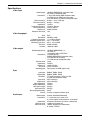
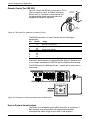
QUICK START FOR SYSTEM 5cr SWITCHER
Connections
S-video
1. Rear Panel Inputs
PC2 and PC3 –
Connect RGBS/
RGBHV sources,
such as from
Computer-Video
Interfaces. Connect
Audio if available.
S-video
2. Rear Panel Inputs
VID1 & VID2 – Connect
S-video
Composite Video or S-video sources and Audio, if
available. (Use Setup and then procedure “b” below to select Composite or S-video.)
3. Outputs – Connect RGBS/RGBHV, S-video and Composite Video to the Display Device (Projector), as required.
Connect Audio Preamp output to the input of a sound system or Amplified Out directly to Speakers.
4. Other – Connect RS-232 Host, SCP 100(s), Power Sensor, Room/Relay control and IR Emitter or Broadcaster.
5. Front Panel Input PC1 – Connect a VGA and Audio source (Laptop) to this input at any time.
6. Power – Apply power to the System 5cr and other devices.
Composite or S-video
7. Setup – Follow the
procedures below
to clear or set up
Audio levels, VID1
& VID2 input
formats and IR
learning (Projector
control, etc.)
Setup Mode procedures
Enter Setup Mode, and then continue to procedure a, b, or c.
Use Setup Mode for each of the following procedures. To enter Setup Mode, press and hold all 3 Display buttons
(Power/Mute/Mode) on the front panel for 2 seconds. The Config LED lights. Continue to Clear, or to procedure a, b or
c. Once in Setup Mode (Config LED still On), you may move from one
procedure to another without returning to Normal operation. To Exit Setup
Mode, hold the same 3 Display buttons for 2 sec., or wait for 20 second
time-out (3 LEDs blink during the last 5 seconds).
To Clear existing configuration(s) (to factory default)
From Setup Mode, double-click the Room button. The Room LED blinks for
8 seconds. During that time, do one of the following:
Clear One – press the desired button to clear only its IR configuration.
Clear ALL (IR & other settings) – press all 3 Display buttons 2 seconds.
To Exit Clear, press the Room button.
a - Preset Attenuation for Audio Inputs – Audio must be present on each input, playing a loud
passage from each source, then use the following procedure to set each input.
1a. Double-click (press twice) the button for the Input to be adjusted. Its LED will blink continuously.
2a. Adjust Volume knob up (cw) until Clip LED is On or blinking frequently with sound level.
3a. Adjust Volume knob down (ccw) just until Clip LED is Off or blinks occasionally as the level peaks.
4a. Press the Input button again to save the setting.
5a. Repeat steps 1a through 4a for each audio input.
6a. While still in Setup mode, you may move directly to another procedure, or exit to normal mode.
b - Select input format for VID1 & VID2 (default = comp. video) In Setup Mode, do the following:
1b. Press & hold the Room button until finished with this operation. After 2 seconds, one of the VID1
LEDs lights. (During this operation, the appropriate LED lights to indicate the selected format.)
2b. Press VID1 input button to toggle between VID (Comp. Video) and Y/C (S-video) formats.
3b. Repeat step 2b to select the format for VID2 input.
4b. Release the Room button to return to Setup mode.
5b. While still in Setup mode, you may move directly to another procedure, or exit to normal mode.
c - Learn Infrared Signals from other devices’ remotes. In Setup Mode, do the following:
1c. Press the System 5 button to be programmed for 2 seconds. Config LED blinks to indicate “ready”.
2c. Point the IR source remote control directly at the System 5 IR Remote window and press the
button for the signal to be “learned”. Config remains On while TX & Retry LEDs blink to indicate
that the operation is complete. (If Retry = On and TX - Off, repeat this step).
Note: The Display Power button can learn 2 functions. See LED codes below for other responses.
3c. Repeat steps 1c and 2c to program the next button.
4c. While still in Setup
mode, you may move
directly to another
procedure, or exit.
Contents
cr
Chapter One • Introduction to System 5cr
What is a System 5cr Switcher? ................................................................................................. 1-1
Controlling the System ................................................................................................... 1-1
Infrared learning for System Control .............................................................................. 1-2
Standard Features ......................................................................................................... 1-2
Inputs ............................................................................................................................. 1-2
Outputs .......................................................................................................................... 1-2
Options and Accessories ............................................................................................................ 1-3
Specifications ............................................................................................................................. 1-4
Chapter Two • Rear Panel Connections
Installation in Rack, on a Wall or Under a Table .......................................................................... 2-1
Panel Connections ..................................................................................................................... 2-1
Video Input Connections ................................................................................................ 2-1
Audio Input Connections ................................................................................................ 2-2
Video Output Connections ............................................................................................. 2-2
Audio Preamp Out Connection ...................................................................................... 2-4
Connecting Accessories ............................................................................................................. 2-4
Comm connector and Infrared Emitter ........................................................................... 2-5
Room/Relay connector .................................................................................................. 2-5
cr
Chapter Three • Using the System 5cr
Using the System 5cr .................................................................................................................. 3-1
Front Panel Controls and Indicators ............................................................................... 3-1
Configuration Setup from the Front Panel................................................................................... 3-3
Infrared Programs and Libraries .................................................................................... 3-3
Enter Setup (Config) Mode ......................................................................................................... 3-3
Clear Configuration(s) .................................................................................................... 3-3
Preset Audio Input Attenuation Levels ........................................................................... 3-3
Select format for VID1 and/or VID2. ............................................................................... 3-4
Learn Infrared Signals from other devices’ remote controls. .......................................... 3-4
Remote Operation ...................................................................................................................... 3-5
Chapter Four • Windows® Control Software
Installing Windows® Control Software ........................................................................................ 4-1
Program Help ............................................................................................................................. 4-2
Program Operation ..................................................................................................................... 4-2
Power Up/Down Delay times ......................................................................................... 4-3
Auto Set Attenuators (set all audio input to the same level). .......................................... 4-3
Room Relay Mode (Latched/Momentary) ...................................................................... 4-3
RGB Delay Times .......................................................................................................... 4-4
Miscellaneous Options ................................................................................................... 4-4
Downloading from Extron’s IR Projector Library ......................................................................... 4-5
Saving a Configuration to a File ..................................................................................... 4-5
Loading Projector Drivers .............................................................................................. 4-6
cr
Appendix A • Programming the System 5cr
Remote Control Port (RS-232) ................................................................................................... A-1
Host-to-System 5 Instructions ..................................................................................................... A-1
Simple Instruction Set – Command codes ..................................................................... A-2
Definitions and Abbreviations: ........................................................................................ A-2
Advanced Instructions – Reserved for Windows program .......................................................... A-3
Appendix B • Reference
System 5 Options ....................................................................................................................... B-1
Glossary of terms ........................................................................................................................ B-3
Index ........................................................................................................................................... B-7
System 5cr Switcher User’s Manual
68-388-01, Rev. A, 09-99
i
Extron • System 5cr Switcher • User’s Manual
System 5cr Switcher
User’s Manual
1
Chapter One
cr
Introduction to System 5cr
What is the System 5cr ?
Control of the Entire A/V System
Infrared Learning
Features & Options
Specifications
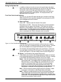
Introduction and Features • Chapter 1
cr Switcher?
What is a System 5cr
Throughout this manual, the terms System 5 and System 5cr are both
used to refer to the same product.
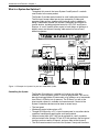
The System 5 provides central control for small audio/video installations.
The five inputs accept video formats from composite, S-video and
computer-video sources, together with line-level audio. In addition to
being a video/audio switcher, the System 5 combines the functions of
several devices, including projector control for LCD, DLP and Plasma
Displays. A “room” function allows control of such things as lighting or a
display screen and infrared “learning” adds control for one of many
different projectors.
ROOM
POWER
DISPLAY
MUTE
AUDIO
MODE
PC1
PC2
PC3
VID1
AUDIO
VID2
VID
VID
Y/C
Y/C
PC1 INPUT
COMPUTER
IR REMOTE
MAX.
CLIP
MIN. VOLUME
TX
CONFIG
RETRY
Front
IR 40
Remote
RGB 406 Interface
Control Pad
Laptop Computer
IR REMOTE
INPUT
AUDIO
DISPLAY
HIGH Z
ROOM
POWER
MUTE
MODE
VOLUME
MAX.
CLIP
75 Ohm
MIN.
PC1
Video Cassette
Player
PC2
PC3
VID1
VID2
LCD Projector
SVGA Compatible
Computer w/ Audio
SCP 100
Composite
100-240V
1.3A
R
R
G
G
B
PC 2
PC 3
B
H/HV
H/HV
V
V
L
L
R
R
V/Y
VID 1
VID 2
V/Y
C
C
To Second Control Pad
L
L
R
R
R
Y
G
B
H/HV
C
PREAMP OUT
L
R
VID
V
AUX 1
AUX 2
RELAY
RS-232
AMPLIFIED OUT
COMM.
L
L
R
R
DISPLAY PWR
SENSOR
50/60 Hz
Rear
S-video
Computer
Interface
SVGA Compatible Computer
Document Camera
Powered Speakers
Speakers
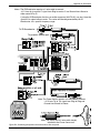
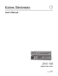
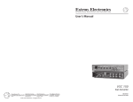
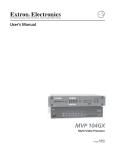
Figure 1-1. Example of a System 5 as part of a video/audio system.
Controlling the System
The System 5 functions as a switcher as it comes out of the box.
However, to have projector control, it must be programmed. This can be
done by learning projector IR commands or by loading a set of commands
from Extron’s IR library into its memory. The IR library, as well as the
latest control software is available at www.extron.com. Control of the
System 5 and other devices can be done in several ways:
• The front panel
• Windows® control software from a PC
• Through RS-232 port by a PC, a touch screen panel, or any other device
capable of sending and receiving the serial port protocol.
• Optional control pads (SCP 100) can be mounted in a wall, or podium,
and hard-wired to the System 5. Each SCP 100 replicates the front panel
functions and can receive IR signals, and pass them to the System 5.
• The IR 40 remote control has each of the System 5 front panel functions.
1-1
Extron • System 5cr Switcher • User’s Manual
Chapter 1 • Introduction and Features
Infrared Learning for System Control
The IR receiver window on the front panel also serves as a learning port
to add IR signals from other sources to the System 5 panel functions.
Then, when a panel function is selected, the learned IR signal is
transmitted into the room through the hard-wired IR emitter, or the
optional IR Broadcaster, to be received by the projector. IR commands for
the projector can be associated with each of the Display buttons (Power,
Mute and Mode) on the front panel as well as with each of the five input
buttons. Thus the System 5 switcher can control the projector. Stored
commands (learned or uploaded) in the System 5 memory are also
effective when using the IR 40, SCP 100 or RS-232 controls.
As an example, IR commands for the projector shown in Figure 1-1 can
be stored in the System 5 memory such that when the VID1 input is
selected, the projector will switch to its composite video mode. Selecting
VID2 input could send a command to tell the projector to switch to S-video
mode.
Standard Features
•
•
•
•
•
•
•
•
•
•
•
•
•
250 MHz bandwidth (-3 dB)
Audio preamp with 2-channel stereo outputs
Audio breakaway (switch audio and video separately, with RS-232)
Audio input levels may be preset individually and then adjusted by the
master volume control.
Five Inputs - computer video, RGBS, RGBHV, composite video or S-video
Internal audio amplifier - 12 watt/channel, with adjustable output
Room control - relay control of lights, window shades, display screen, etc.
Projector control - display power, mute, mode (learned IR commands)
Learns IR remote commands - from a library or through the front panel
Memory stores IR commands that are learned, or uploaded through a PC.
(Procedure in Chapter 4.)
RS-232 programming, with Simple Instruction Set (SIS)
Triple-action switching (blank screen while switching between inputs)
Special mounting brackets allow the System 5 to be mounted on a wall or
under a table, plus standard brackets are included for rack-mounting.
Inputs
_______ The four rear panel inputs described here include a 5-pole, captive screw
connector for 2-channel stereo audio, balanced or unbalanced signals.
• Computer video input is provided on the front panel through a VGA
(female HD 15 pin) connector (PC1). This allows for quick connection of a
laptop computer without having to access the rear panel of the switcher.
• Computer video may also be connected through BNC connectors to the
PC2 and PC3 inputs, through an interface, such as an RGB 406, as
shown in Figure 1-1.
• The VID1 and VID2 inputs can be either composite or S-video signals,
both through BNC connectors.
Outputs
• The System 5 provides video outputs for RGBS, RGBHV, Composite and
S-video formats. One output is active at any one time.
• Audio preamp output for either balanced or unbalanced audio signals is
available through a 5-pole, captive screw connector.
• An internal, 12 watt/channel audio amplifier drives non-powered speakers.
• Stored IR commands output through emitter or broadcaster.
Extron • System 5cr Switcher • User’s Manual
1-2
Introduction and Features • Chapter 1
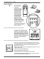
Options and Accessories
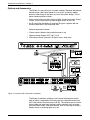
The System 5 is more than just a system switcher. Standard and optional
features make it the control center for a small A/V system by adding
control of other things in the room as part of the system design. Two of
these standard features include:
• Room control allows for relay control of lights, window coverings, display
screen, or most anything the system designer wants to use it for.
• An IR transmitter distributes all incoming IR signals, together with the
learned commands in the immediate area.
Optional equipment includes:
• Current sensor (detects when projector power is on)
• Optional remote keypad, SCP 100 (1 or 2)
• IR broadcast device (transmits IR signals over a wide area)
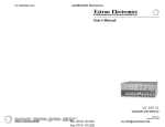
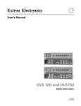
Figure 1-2. System 5 with accessories and options
The System 5 combines switching, room control and projector control,
each of which is controlled at the front panel, by hard-wired control pad
(SCP 100) and by IR remote control (IR 40). The switcher can be used to
control video and audio input settings, display functions such as power,
mute and video modes, and room controls, such as lowering or raising a
display screen or powering lights on or off.
1-3
Extron • System 5cr Switcher • User’s Manual
Chapter 1 • Introduction and Features
Specifications
Video input
Number/type _
_
Connectors _
_
_
Nominal level(s) _
Maximum level(s) _
Impedance _
Horizontal frequency _
Vertical frequency _
Return loss _
Maximum DC offset _
3 RGBHV/RGBS/RGsB computer video
2 S-video or composite video
1 15-pin HD female (RGB computer video)
2 x 5 BNC female (RGB computer video)
2 x 2 BNC female (S-video or composite video)
Analog — 0.3 to 1.45V p-p
Analog — 2.0V p-p
75 ohms
15 kHz to 150 kHz
30 Hz to 150 Hz
-45dB @ 5 MHz
1.5V
Video throughput
Gain
Bandwidth
Frequency response
Differential phase error
Differential gain error
Crosstalk
Isolation
_
_
_
_
_
_
_
Unity
250 MHz (-3dB)
< ± 0.1dB to 30 MHz
0.01º, 0 to 10 MHz
0.01%, 0 to 10 MHz
-50dB @ 5 MHz
+50dB @ 5 MHz
Video output
Number/type/format _
_
_
Connectors _
_
_
_
Nominal level _
Impedance _
Return loss _
DC offset _
Switching type _
1 RGBHV/RGBS/RGsB, or
1 S-video, or
1 composite video (NTSC/PAL)
1 x 5 BNC female
(RGBHV/RGBS/RGsB computer video)
1 x 2 BNC female (S-video)
1 x 1 BNC female (composite video)
1V p-p
75 ohms
-38dB @ 5 MHz
±5 mV maximum
Triple action (for RGB signals only)
Sync
Input type _ RGBHV, RGBS, RGsB
Output type _ RGBHV, RGBS, RGsB
Standards _ TTL (RGB computer), NTSC and PAL
_ (S-video and composite video)
Input level _ 0.5V to 5.0V p-p
Output level _ 0.5V to 5.0V p-p
Input impedance _ 75 ohms
Output impedance _ 75 ohms
Max input voltage _ 5.0V p-p
Input sensitivity _ 5.0V p-p
Max. propagation delay _ 20 nS
Polarity _ Positive or negative (follows input)
Audio input
Number/type _ 5 stereo, balanced/unbalanced
Connectors _ 1 3.5 mm mini jack, stereo, PC1
_ 4 3.5 mm captive screw terminals, 5 conductor
Impedance _ 25 k ohms, balanced; 50 k ohms, unbalanced
Minimum level _ -10dBu for full power out
Maximum level _ +20dBu, (balanced or unbalanced)
_ @ stated %THD+N
Extron • System 5cr Switcher • User’s Manual
1-4
Introduction and Features • Chapter 1
Audio throughput
Gain
Frequency response
THD + Noise
S/N
Adjacent input crosstalk
Stereo channel separation
Total harmonic distortion
CMRR
_
_
_
_
_
_
_
_
-78dB to +40dB
±0.05dB @ 20 Hz to 20 kHz
< 0.1% @ 1 kHz, at rated maximum output
>95dB, 21dBu output
>80dB @ 1 kHz
>90dB @ 1 kHz
0.03%, worse case, @ 1 kHz at rated preamp drive
>75dB @ 20 Hz to 20 kHz
Number/type
Connectors
Impedance
Drive (HI-Z)
Drive (600 ohm)
_
_
_
_
_
1 stereo, balanced/unbalanced
1 3.5 mm captive screw terminal, 5 conductor
50 ohms unbalanced, 100 ohms balanced
> +21dBu, balanced/unbalanced at stated %THD+N
> +15dBm, balanced/unbalanced at stated %THD+N
Number/Type
Connectors
Protection
Drive (full power out)
_
_
_
_
1 stereo, 12 watts/channel
2 captive terminals, L/R +/-, spring loaded
Thermal, short circuit, open circuit, overload
12 watts per channel, 8 ohm load
Audio output — preamp
Audio output — power amp
Control/Remote — switcher
Serial control port
Baud rate and Protocol
Pin configuration
Extron remote key pad control
_
_
_
_
_
IR controller module _
Program control _
_
RS-232, 9-pin female D connector
9600, 8-bit, 1 stop bit, no parity
Pin 2 = TX (RS-232), 3 = RX (RS-232), 5 = GND
2 5 mm captive screw connectors,
5 conductor (auxiliary ports)
30 kHz to 60 kHz input frequency compatibility
Extron’s Windows® control program
Extron’s Simple Instruction Set - SIS
Control — room relay
Number/type _ 1 momentary or latching
Connector _ 1 3.5 mm captive screw connector, 5 conductor
Contact rating _ 24V, 1 amp
Control — projector
Projector control port _ 1 3.5mm captive screw connector, 5 conductor
General
Power _
_
Temperature/humidity _
_
_
_
Rack mount _
Enclosure type _
Enclosure dimensions _
_
Shipping weight _
Vibration _
_
Approvals _
MTBF _
Warranty _
100VAC to 240VAC, 50/60 Hz, 70 Watts,
internal, auto-switchable
Storage -40° to +158°F
(-40° to +70°C) / 10% to 90%, non-condensing
Operating +32° to +122°F (0° to +50°C) /
10% to 90%, non-condensing
Yes, with included brackets
Metal
1.75" H x 17" W x 10.1" D
4.4 cm H x 43.2 cm W x 25.7 cm D
10 lbs (4.5 kg)
NSTA 1A in carton
(National Safe Transit Association)
UL, CUL, CE, FCC Class A
30,000 hours
2 years parts and labor
Specifications are subject to change without notice.
_______ The AUX 1 & 2 ports of the System 5cr provide a total of 500mA. This is
split between the two ports offering 250mA for each port. A 12VDC,
500mA output is provided on the Comm. (IR Emitter) port.
1-5
Extron • System 5cr Switcher • User’s Manual
System 5cr Switcher
User’s Manual
2
Chapter Two
Rear Panel Connections
Mounting – Table or Rack
Input Connections
Output Connections
Connecting Accessories
Making Connections • Chapter 2
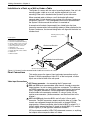
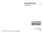
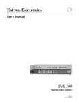
Installation in a Rack, on a Wall or Under a Table
The System 5cr comes with two sets of mounting brackets. One set is for
mounting under a table or on a wall and the second set is for rack
mounting. Either set is attached to the System 5 by four #8 screws.
When mounted under a table on a wall, the bracket will extend
approximately 1/4 inch above the top surface of the System 5 enclosure,
as shown in Figure 2-1. This is designed to have an air space between
the System 5 enclosure and the surface it is mounted on.
A second set of brackets (top example) has slotted holes that face
forward to accommodate rack-mounting hardware. When attached to the
System 5 enclosure, the forward-facing holes will align with the holes in a
standard rack.
Mounting Screws (2 Plcs)
Each Side
Included parts:
2 – brackets for rack mounting
2 – brackets for table/wall mounting
9 – 5-pole, captive screw connectors
1 – IR emitter, with connector cable
1 – phono-style audio connector
1 – IEC power cord
1 – IR 40 remote, with batteries
1 – Floppy disk with control software
4 – rubber feet
1 – Extron tweaker
Rack-mount Brackets
-232
RS
T
D OU
IFIE
PL
L
AM
or
X1
AU
X2
AU
Y
LA
RE
.
MM
CO
R
L
R
V
V
H/H
B
G
R
Table/wall-mount Brackets
R
Y PW
LA NSOR
DISP SE
T
OU
MP
EA R
PR L
VID
C
Y
R
L
C
R
V/Y
R
L
V
B
#8 Screw (4 Plcs) Each Side
/60
50
L
C
L
V
V
H/H
G
2
PC 3
B
PC
R
G
A
1.3
V
40
0-2
10
1
VID 2
VID
V/Y
R
V
H/H
R
Hz
Figure 2-1. System 5 can be mounted under a table or to a wall or in a rack.
Panel Connections
This section covers the types of input and output connections on the
System 5. With the exception of input PC1 on the front panel, all other
inputs are on the left side of the rear panel.
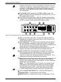
Video Input Connections
8
9
10
2-1
IEC Power connector – for connecting the AC power cord.
PC2 and PC3 inputs accommodate video formats, through a computervideo interface, as well as stereo audio from a computer. The video can
be RGBS (composite sync) or RGBHV (separate horizontal and vertical
sync), using BNC connectors. Connect balanced or unbalanced, 2channel audio to the connector marked L R, using a 5-pole, 3.5 mm
captive screw connector. (Audio connectors are discussed later in this
chapter.)
VID1 and VID2 each have two BNCs and a 5-pole, 3.5 mm audio
connector. The BNC connectors accept composite video or S-video. The
formats are configured through the front panel, or through RS-232
programming. Connect composite video to the left BNC, marked V/Y. If
using S-video, connect the luma (Y) signal to the left BNC (V/Y) and the
chroma signal (C) to the right BNC connector marked C.
VID Input sources could be VCRs DVDs document cameras, or anything
that outputs either composite video or S-video.
Extron • System 5cr Switcher • User’s Manual
Chapter 2 • Making Connections
Figure 2-2a. The left side of the rear panel has four of the five inputs.
6
PC1 input is on the Front Panel and accepts laptop
video through a VGA connector as well as 2-channel
audio through a 3.5 mm jack, as shown in Figure 2-2.
With a buffered output, VGA signals can be driven up
to 50 feet without additional amplification.
Figure 2-3. PC1 Input is on the Front Panel.
Audio Input Connections
Connect balanced or unbalanced, 2-channel audio to the input connectors
marked L and R, using a captive screw connector. Possible connections
are shown in Figure 2-4b. Connectors are included with each System 5,
however, cables are the responsibility of the installer.
Figure 2-4a. Audio Input can be connected three different ways with the captive screw connectors.
Strip about 0.25” of insulation from each wire and
insert it into the appropriate connector hole. Do not
solder the wires. Turn the screw counterclockwise to
allow the opening to accommodate the wire. Turn the
screw clockwise to secure the wire in place. Repeat
for each wire.
Figure 2-4b. Connecting audio wires in a captive screw connector.
The PC1 audio input uses a 3.5 mm, round stereo connector, as shown in
Figure 2-4c. Unscrew the barrel of the connector to expose the inside
connections. Slide the barrel over the cable, as shown here. Cut and strip
a wire to an appropriate length for each of the ring, tip and sleeve solder
points. Insert each wire into its respective hole and solder it in place.
Figure 2-4c. Audio Input for PC1.
Video Output Connections
The System 5 has BNC output connectors for three video formats
(RGBHV, Composite, and S-video). Which output connectors are active
depends upon the format of the selected input. The green LED to the right
of each connector, or set of connectors, lights to show which output is
active. Only one output is active at any one time.
Extron • System 5cr Switcher • User’s Manual
2-2
Making Connections • Chapter 2
_______ Although all three outputs may be connected at the same time, only one
can be active at one time, as determined by the input format. In a typical
installation, an LCD projector may have inputs for all three formats. In
such cases, each of the three System 5 outputs would be connected to
the same projector.
11
12
R, G, B, H/HV, V BNC connectors, for RGBS or RGBHV output. The
green LED indicates when the selected input is RGB format (PC1, PC2 or
PC3) and this output is active.
Y and C BNCs for S-video output. A BNC-Din adapter may be required.
The green LED indicates when the selected input is S-video format (VID1
or VID2, if set up for S-video format) and this output is active.
Figure 2-5. The right side of the rear panel has three video outputs, plus audio and options.
VID is for Composite video output. The green LED indicates when the
selected input is composite video format (VID1 or VID2, if set up for VID
format) and this output is active.
14 Audio PreAmp Out – This output has the audio signal from the selected
input and should be connected to a stereo audio amplifier. The signal is
the same as item 18, at a low level. Both audio outputs are affected by the
volume control. See detailed section on audio connectors.
_______ Audio breakaway is available if programmed through RS-232. If so, the
selected audio input may be different from the selected video input.
13
Aux1 and Aux2 each can accommodate a connection to an optional
external control panel (SCP 100). See the SCP 100 User’s manual and
“Connecting Accessories” later in this chapter. See specifications
_______ The AUX 1 & 2 ports of the System 5cr provide a total of 500mA. This is
split between the two ports offering 250mA for each port.
15
Relay Contacts (one normally open pair and one normally closed pair) are
controlled by the “Room” button on the front panel to control external
functions, such as lighting, display screen up/down, etc. See “Connecting
Accessories” later in this chapter.
Comm – This is the connection for the IR emitter or the optional remote
IR Broadcaster. Both of these devices transmit only learned IR signals
from the System 5 to the projector, IR 40 commands are not included.
The optional Broadcaster covers a much wider area than the emitter.
_______ A 12VDC, 500mA output is provided on the Comm. (IR Emitter) port.
16
17
18
19
2-3
Optional Display Power Sensor Input – Detects projector power on.
Amplified Output – connect directly to audio speakers.
RS-232 Control Port – connect a host, such as a touch panel, a PC, etc.
Extron • System 5cr Switcher • User’s Manual
Chapter 2 • Making Connections
Audio Preamp Out Connection
Connect balanced or unbalanced, 2-channel audio to the Preamp Out
connector marked L (Left) and R (Right), using a captive screw connector.
Possible connections are shown in Figure 2-6. Connectors are included
with each System 5, however, cables are the responsibility of the installer.
Use the same procedure as for the audio input captive screw connectors.
Figure 2-6. Audio Preamp Output can be connected three different ways.
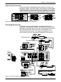
Connecting Accessories
The System 5 can have several options and accessories that use
connectors in the rear panel. Figure 2-7 shows four of the captive screw
connectors for the Room Relay, IR Emitter or IR Broadcaster and the two
SCP 100 remote panels. There is also one round connector for an
optional Display power Sensor. Each accessory product has its own
user’s manual and is also summarized in Appendix B of this manual.
To IR Broadcaster
To projector remote jack
Figure 2-7. System 5 accessory and option connections.
Extron • System 5cr Switcher • User’s Manual
2-4
Making Connections • Chapter 2
3.5 mm, 5-pole captive screw connectors are used for the audio inputs
and one output, as well as for accessories. These include:
• Aux1 & Aux2 – SCP 100 remote panels (2 optional)
• Relay – Room/relay custom control (standard feature)
• Comm – projector control through the standard IR Emitter or the optional
IR Broadcaster.
One three-contact stereo phono-type of connector is provided for the
optional Display Power Sensor. This device detects when the projector
power is on.
All connectors are provided. Cables are the responsibility of the installer.
The two standard accessories described in this section are the Infrared
Emitter and the Room/Relay custom control. Figures 2-7, 8 and 9 show
accessory connections. Optional devices (SCP 100, the IR Broadcaster
and the Power Sensor) are also covered in their separate user’s guides
and are summarized in Appendix B of this manual.
Comm Connector and Infrared Emitter
This connector is for projector control,
and can be used in different ways:
1a. Connect the IR Emitter (included) to
transmit all of the “learned” IR
commands to the projector. The IR
Emitter includes a black cable with two
wires, one has a white stripe. Insert the
wire with the white stripe into the
carrier/signal pin (C) and the solid black
wire to either ground contact (B or D).
1b. If a wired remote can be plugged into
the projector, that cable will use pins A
(signal) and B, as shown in Figure 2-7.
Figure 2-8. The IR Emitter can be used from the Comm connector or through an IR Broadcaster.
2. To install and use the optional IR Broadcaster, and to use emitter with the
IR Broadcaster, see user’s guide 68-392-02. For some projectors, the IR
Emitter must be used with the broadcaster.
The standard IR Emitter transmits infrared signals over a short, narrow
range, while the IR Broadcaster covers a wider, longer area. Both of these
devices transmit only the IR commands that have been stored in the
System 5, either through “learning” or by uploading from Extron’s IR
library. If the broadcaster is installed, the emitter may not be needed.
Room/Relay Connector
The Room Relay contacts are shown in Figure 2-9. One relay has two
sets of contacts – one set is normally closed and the other is normally
open. When the Room function is active, the normally closed contacts are
open and the normally open contacts are closed.
normally
closed
normally
open
The contacts can be programmed to operate either of
two ways: latched (press-on, press-off) and momentary
or timed (press-on, time-out-off, default = 1/8 second).
Timing can only be set through Windows® control
software, through a PC.
to Room
control
equipment The system designer can use these contacts any way
he/she desires as long as the contact specifications of
24 volts at 1 ampere are not exceeded.
Figure 2-9. The Room Relay has two sets of contacts.
2-5
Extron • System 5cr Switcher • User’s Manual
System 5cr Switcher
User’s Manual
3
Chapter Three
cr
Using the System 5cr
Front Panel Controls & Indicators
Configuration:
Audio Preset, VID Formats & IR Learning
Operating the System 5cr • Chapter 3
cr
Using the System 5cr
________ In addition to the basic function of each of the panel buttons described
here, there are also setup procedures that use many of the same buttons
and controls. Each of the Input and Display buttons is capable of
“learning” an IR command. The Display Power button must learn both
power on and power off for the projector. The setup procedures are
described later in this section.
Front Panel Controls and Indicators
On power up, all of the LEDs light and then go off, except for the Power
LED and the LED for the input last selected. On the rear panel, the LED
for the selected input format will be lit.
1
Power and Room
Power LED – Indicates when the System 5 has power.
Room Button and LED – These work with the relay contact connections
provided on the rear panel of the System 5. The button can activate/
deactivate a room condition, such as turn lights on/off and raise/lower a
viewing screen. The LED indicates that the condition is active. Exactly
how the feature is used depends upon the user-defined application and
what is connected to the “Relay” connector on the rear panel.
Figure 3-1a. Front Panel Buttons and Indicators
The Room button can be set to operate in either of two ways: latching
(press on, press off) or momentary (press on, off after time-out). The timeout value can only be set through the Windows® Control Program.
_______ For example, pressing the Room button once could lower a screen and
turn room lights off and the LED will remain lit. Press the button again to
turn the room lights on, raise the viewing screen and the LED goes out.
Display – (customized for the projector being used)
________ These buttons only function after being programmed, either by “learning”,
or by loading the projector’s commands from Extron’s IR library. Learning
is described in the Setup Mode procedures later in this chapter.
2
Power – After this button has been programmed for the projector’s IR
remote commands, it will toggle power to the display device on or off.
Because there is a warm up delay and a cool down delay for many
projectors, the Display Power LED will blink fast during projector
power up and will blink slowly during projector power down. The
blinking time is generated within the System 5; it does not come from
the projector. Its duration can be programmed through RS-232.
Mute – After this button has been programmed for the projector’s video
mute signal, it will function as the Display Mute on/off switch.
Mode – Effective on display devices that do not automatically detect the
type of video signal, this button can be programmed to change the
mode of the display device between computer-video, composite video
and S-video. This can duplicate the single-button (step) mode function
found on some projector remote controls.
3-1
Extron • System 5cr Switcher • User’s Manual
Chapter 3 • Operating the System 5cr
________ As stated earlier, each input button can be programmed to “learn” an
associated IR command. For example, selecting the PC1 input could also
send a signal to the projector to switch to its computer input mode, and
selecting VID1 could cause the projector to switch to S-video mode, etc.
3
•
•
•
4
5
_______
PC Input Selection Buttons and Indicators:
PC1 – Input select button for computer video and audio. This selects the
input from the VGA and Audio connectors on the System 5 front panel.
PC2 – Input select button for an RGBS or RGBHV source (and audio)
from the PC2 section of the rear panel. This could be from a computer,
through a computer-video interface.
PC3 – Same as PC2 but input is from the PC3 section of the rear panel.
Composite or S-video inputs (VCR, DVD, etc.):
VID1 – 1st input select button for Composite Video or S-video with audio.
VID2 – 2nd input select button for Composite Video or S-video with audio.
Audio Gain (Volume) Control knob for amplified output.
Max LED (red) – lights when the audio output level control has reached its
maximum point. This does not indicate the audio level.
Clip LED – lights when the output level is beginning to overdrive (peak).
This indicator is used to set the audio attenuation for the inputs.
Min LED – lights when the output level control has reached its minimum
point. This does not indicate the audio level.
When all audio inputs are at the same level coming into the System 5cr,
the Volume knob functions as the master volume control for both audio
outputs. (See Setup Mode procedures later in this chapter.)
PC1 Input connectors – Audio and Computer VGA connectors selected
by the PC1 button. Connect a VGA cable to the 15-pin HD connector.
Plug the computer’s audio output to the audio jack.
_______ Each of the controls described above are duplicated on the IR 40 remote
control, on the optional SCP 100 panels, and on the Windows® control
software. The operation is the same, including associated IR commands.
6
Figure 3-1b. Front panel controls and indicators
IR Function LEDs and Infrared Receiver/Learner Port – In addition to
each LED having its function, in combinations they indicate other things.
TX LED (green) – lights when System 5 is transmitting infrared signals.
Flashes with Config and Retry LEDs to indicate a time-out condition
for the configuration mode.
Config LED (amber) – When steady on the System 5 is in setup mode and
is ready to be configured. See the Setup Mode procedures for ways in
which this indicator is used in combination with other LEDs.
Retry LED (red) – Indicates the System 5 has failed to recognize a command
in the infrared learning process.
IR Remote – window receives signals from the IR 40 for normal operation, as
well as from other remote control sources when learning commands.
7
Extron • System 5cr Switcher • User’s Manual
3-2
Operating the System 5cr • Chapter 3
Configuration Setup from the Front Panel
For the System 5 switcher to control other equipment in the A/V system, it
must be configured from the front panel, or through an RS-232 device.
This cannot be done from an IR 40 or SCP 100. See Chapter 4 for
Windows® Control program and Appendix A for RS-232 instructions.
Infrared Programs and Libraries
Extron provides a library of drivers for most projectors. To download a
driver from the library, see the procedures located in Chapter 4. A typical
projector driver assigns projector IR commands to the System 5 panel
functions such that the Display Power, Mute and Mode functions can
control the projector. Also, once programmed, selecting PC1, PC2 or PC3
inputs can set the projector to RGB format, while VID1 and VID2 can set
the projector to either S-video or Composite Video. Selection can be from
the front panel or by remote. To configure the System 5 from the front
panel, use the following procedures.
Enter Setup (Config) Mode
Each of the procedures in this section is done from Setup (or Config)
Mode. Once in Setup Mode (Config LED = On),
you may go from one procedure to another
without returning to Normal Mode.
To enter Setup Mode, press and hold all 3
Display buttons (Power/Mute/Mode) for 2
seconds. The Config LED lights. Go to the
appropriate procedure. Pressing the same 3
buttons will also exit Setup (Config) mode.
Figure 3-2a. Enter Setup Mode from the Front Panel.
Clear Configuration(s)
To Clear existing configuration(s) to the factory default, from Setup Mode,
double-click the Room button. The Room LED blinks for 8 seconds.
During that time, do one of the following:
Clear One – press the desired button to clear only its IR configuration.
Clear ALL – press all 3 Display buttons (Power/Mute/Mode) at the same
time for 2 seconds to reset all IR and other settings to factory defaults.
Preset Audio Input Attenuation Levels
For the Audio Volume control to act as a “master” control for all inputs, all
audio inputs must be set for same level. With audio input signals
connected and active, enter Setup Mode and do the following:
1a. Press the input button twice (double-click) for the audio input to be
adjusted. The input LED blinks.
2a. Slowly adjust the Volume knob up (cw) until Clip LED is On or blinking
frequently with changes in sound level.
3a. Adjust Volume down (ccw) just until Clip LED is Off or blinks occasionally
as the level peaks.
4a. Press the input button again to save the setting.
5a. Repeat steps 1a through 4a for each audio input.
6a. While still in Config mode, you may go directly to another procedure, wait
for 20 second time-out or press and hold all 3 Display buttons for 2
seconds to force a return to normal operation.
Figure 3-2b. Set the audio input attenuation to the same levels.
3-3
Extron • System 5cr Switcher • User’s Manual
Chapter 3 • Operating the System 5cr
Select format for VID1 and/or VID2.
To set these two inputs for either Composite or S-video, in Config Mode,
do the following:
1b. Press and hold the Room button until finished with this operation.
After 2 seconds, one of the VID1 LEDs lights.
2b. Press VID1 to toggle between VID (Video) and Y/C (S-video) formats.
3b. Repeat step 2b to select the format to set the format for the VID2 input.
4b. Release the Room button to go back to Config mode.
5b. While in Config mode, you may go directly to another procedure, wait for
20 second time-out or press all 3 Display buttons for 2 seconds to exit.
Figure 3-2c. Select input format for VID1 and VID2.
Learn Infrared Signals from other devices’ remote controls
This procedure is only necessary if the IR driver is
not available for the system projector, or is not
complete. A flow chart of the learning procedure is
shown in Figure 3-2d and a table of LED codes is
shown in Figure 3-2e. In Setup Mode, do this:
1c. Press the panel button to be programmed and hold
it for 2 seconds. The Config LED blinks.
2c. Point the IR remote source at the System 5 IR
Remote window and press the button briefly, but
firmly, for the signal to be “learned”.
Figure 3-2d. Learn infrared signals from other remotes.
_______ It may be necessary to hold remote as near as 1/2 inch and point it
directly into the IR window. It may also help to block out ambient light,
such as from fluorescent sources.
The Config LED remains On while TX & Retry LEDs flash to indicate
that the operation is complete. (If Retry blinks once and TX - Off, repeat
this step). See LED codes in Figure 3-2e below.
_______ The Display Power button learns 2 signals. After learning the 1st signal
(e.g. Power On), the Config and Retry LEDs blink to indicate that it is
ready to learn the second signal (Power Off). Double-click the Power
button and repeat step 2c to learn the second signal.
3c. Repeat steps 1c and 2c to program the next button.
4c. While in Config mode, you may go directly to another procedure, wait for
20 second time-out or hold all 3 Display buttons for 2 seconds to exit.
________ Once the display device (projector) has been programmed to operate
from the System 5cr, those same control functions should not be done
from the projector because the System 5 has no way of knowing what was
done at the projector. That is, if the projector was turned on at the
System 5 and turned off from the projector panel, the System 5 thinks the
projector is still on.
Figure 3-2e. LED response codes
Extron • System 5cr Switcher • User’s Manual
3-4
Operating the System 5cr • Chapter 3
Remote Operation
________ See inset (top, right)
to install batteries.
The System 5
includes one infrared
remote control (IR 40)
and can have one or
two optional remote
control panels (SCP
100). Each of these
devices replicate the
front panel controls
for normal operation.
Learning and other
things done in Setup
Mode cannot be done
from these remote devices.
The IR 40, shown in Figure
3-3, uses + and - buttons for
Volume up and down.
The Function and Enter buttons
on the IR 40 do not affect the
System 5 operation.
Figure 3-3. The IR 40 has the same controls as the front panel.
The optional SCP 100 panels can be
mounted in a wall or piece of furniture,
such as a desk or podium. In addition to
duplicating front panel controls, they also
receive IR 40 signals and pass them to
the System 5. Infrared signals from other
devices are blocked at the System 5, and
do not pass on to the IR emitter or
broadcaster.
Figure 3-4. The optional SCP 100 also passes IR 40 signals to the System 5.
Other ways to control the System 5 include using the RS-232 serial port.
This can be through a host, such as a touch-screen panel or a PC, using
the Windows® operating system. RS-232 programming is covered in
Appendix A of this manual.
Certain operations can be done only through Extron’s System 5cr Control
Program, these include:
• Room Relay Mode (Latched/Momentary)
• (projector) Power Up/Down Delay times
• Auto Set Attenuators (set all audio input to the same level).
The use of Extron’s Windows® Control Program is covered in Chapter 4
and RS-232 programming is in Appendix A.
3-5
Extron • System 5cr Switcher • User’s Manual
System 5cr Switcher
User’s Manual
4
Chapter Four
Windows® Control Software
Installing the Windows Control Software
Program Help
Program Operation
Downloading IR Projector Drivers
Windows® Control Software • Chapter 4
Installing Windows® Control Software
This control program communicates with the System 5 Switcher through
the RS-232 port on the rear panel of the System 5. Extron supplies this
software that runs in the Windows® operating system, version NT, 95, or
later. The program presents most of the same functions found on the
unit’s front-panel, but through an interactive graphical interface. There are
some additional features/settings that are only available through the
Configure Unit Screen of this program.
1. Connect the PC’s Comm port to the RS-232 port on the System 5, as
shown in Figure 4-1.
2. Power up the System 5 and the PC with the Windows operating system.
3. To install the software, run Setup.exe from the floppy disk #1. (just like
any other Windows application.) Insert disk #2 when prompted to do so.
B
H/HV
V
AUX 1
AUX 2
RELAY
PREAMP OUT
L
R
VID
RS-232
AMPLIFIED OUT
COMM.
L
L
R
R
DISPLAY PWR
SENSOR
______ The floppy disk has
instructions printed on
the label.
Figure 4-1. Connect the PC to the System 5.
Follow the prompts to set up the program. To run the control software do:
Start | Programs | Extron Electronics | System 5cr Control Pgm
Figure 4-2. System 5 Program
Program Help
To learn how to use Help, press F1 from the program, or open it from the
start button.
Start | Programs | Extron Electronics | System 5cr Help
This brings up a picture of the System 5cr Main Screen. For Help on
specific buttons and controls, click the appropriate item above. [Use the
Mouse or the TAB/ENTER keys to get details about the selected area of
the screen]. For Help on specific screens and buttons, click the
appropriate item link at the bottom of the screen, as follows:
Buttons & Controls of the System 5cr Configure Unit Screen (graphically)
Buttons & Controls of the System 5cr Executive Mode Screen (graphically)
Press F1 from within the program to get context-sensitive Help.
4-1
Extron • System 5cr Switcher • User’s Manual
Chapter 4 • Windows® Control Software
○
○
○
○
○
○
○
○
○
○
This is the help screen that appears when
you click the Configure Unit link. Use the
cursor (pointing finger) to display a
description of that section. The operational
version of this screen is used to set/view
various system parameters and to view the
IR command (if any have been learned or
loaded) associated with the various front
panel buttons. Not all of these functions
are available through the unit's front-panel;
some require the Windows Control
Program. Click the Close button to return
to the normal Main screen mode.
The IR params box at the bottom of the
screen shows the command(s) associated
with the selected panel button (top of
screen) for the projector being used.
Figure 4-3. Example of two Help screens for the System 5.
Program Operation
Extron’s System 5cr Control Program replicates a front panel on screen,
including some information and functions that are not on the physical front
panel. There are two different panel screens:
• Executive Mode panel, shown here is a minimum
version, which allows input selection only.
• Configure Unit (next page) includes all front panel, plus
other configuration capabilities. Some operations can be
done only through this Windows program.
Figure 4-4. Example of Executive mode screen for the System 5.
The “Normal” operation panel is like the one shown in the Help screen in
Figure 4-3. Some of the panel controls are explained on the following
page. Some functions can only be done through this panel.
The System 5 comes with factory defaults and no “learned” IR commands
stored in memory. Learning IR codes from the projector’s remote control
is covered on page 3-4. Panel settings made using this software, together
with stored IR codes (learned or loaded) may be saved as a system file
(page 4-4) and restored at another time.
Extron • System 5cr Switcher • User’s Manual
4-2
Windows® Control Software • Chapter 4
Power Up/Down Delay times
1 Many projectors (LCD, DLP, etc.) have a warm-up and cool-down cycle.
During these times, the projector may not accept commands. The times
for each projector may be different. The System 5 has timers that can be
adjusted to represent these delay times, thereby warning the operator not
to send commands while the Power LED is blinking. Slide the scroll bar
for Pwr-Up Delay and/or for Pwr-Dn Delay to match the times required by
the projector being used with the System 5. These settings determine how
long the Display Power LED on the front panel blinks during power up and
power down of the projector. These settings do not control the projector
times; they simulate it. Settings are from 10 to 300 seconds (5 minutes),
in 10 second steps. The factory default is 30 seconds.
Auto Set Attenuators (set all audio input to the same level)
2 With the audio input sources active, click this button to automatically
preset each input to its “Clip” level. Once this is done, the Volume control
(from the front panel, a host or remote SCP 100) will operate as the
master Volume control.
Room Relay Mode (Latched/Momentary)
3 This allows the selection of two modes for customizing the operation of
the Room control function. Depending upon what the designer wants the
function to control, it can operate in either of two ways.
• Latched – click this button to make the Room button operate as follows:
press to activate the relay and press again to deactivate (unlatch) it.
• Momentary – click this button to make the Room button operate as
follows: press the Room button to activate; deactivation takes place after
a prescribed time, as set by sliding the scroll button up or down. The time
value is displayed from 1/8 to 2 seconds, in 1/8 second steps.
________ The Windows® Control Program is the only way to adjust the time
duration for this mode.
Figure 4-5. Example of the System 5 operational screen.
In the System 5 Control program, select one of the Room Relay Mode
buttons. If Momentary is selected, move the scroll bar and observe the
time duration displayed in the box below the scroll bar. Settings are from
1/8 to 2 seconds, in 1/8 second steps. Factory default is for Momentary
Mode at 1/8 second. Thus, when the Room button is pressed, the relay is
active for 0.125 seconds and then becomes inactive.
4-3
Extron • System 5cr Switcher • User’s Manual
Chapter 4 • Windows® Control Software
RGB Delay Times
4
The RGB delay time switches the video off before switching the sync off.
It then switches the sync for the new input before switching the video on.
This assures a stable image on the screen. RGB Delay can be set from
this Windows panel. Slide the scroll bar to select from 0 seconds to 5
seconds, in 0.5 second steps.
5
These options may not be the same on all systems. Each one is
explained in the Help screen by clicking on the panel option. Repeat
Power Down is for projectors that require a second power down command
as confirmation. Click the check box to activate the desired option.
Miscellaneous Options
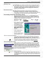
Downloading from Extron’s IR Projector Library
From Extron’s website (www.extron.com), select Download and then
Projector Drivers. A table of projector names, models and drivers will
display. Locate the manufacturer and model and click on the File Name
(hyperlink). Here is an example on one projector:
Manufacturer
Hughes/JVC
Model
G10
File Name
HJC_G10.5CR
Rev. #
A
Rev. Date
11/13/98
After selecting the software
to download, you will be
asked where to save it.
From the File Download
window, select Save this
file to a disk. From the
Save as window direct it to
the path:
(drive):\system5\drivers\
Click the OK button.
Note that projector drivers
have the extension .5cr.
Figure 4-6. Saving the downloaded file.
To activate a projector driver from the Control Software, drop down the
File menu and select Restore Configuration from... and direct it to the
drivers folder (under the System 5 folder) and select the driver file name.
_______ To download the latest version of the System 5 Windows® Control
software, select Download, Control Software, and then System 5cr.
Saving a Configuration to a File
Once a System 5 has been configured, whether it be from downloading,
IR learning, front panel settings, or a combination of these, the current
configuration can be saved as a file (*.sy5) and loaded again later. Any
number of configuration files may be saved and restored. This eliminates
having to set up the system for each application again and again. Saving
and restoring system configuration files is done from the File menu, as
shown in the example to the left.
Figure 4-7. Save and restore a System 5 configuration.
________ The operations described here are subject to change without notice and
are intended as an overview. This includes the System 5 operation as well
as the Extron web site. Use the Help screens for the latest functions and
descriptions.
Extron • System 5cr Switcher • User’s Manual
4-4
Windows® Control Software • Chapter 4
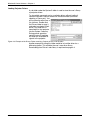
Loading Projector Drivers
A sub-folder under the System 5 folder is used to store the user’s library
of projector drivers.
To view which commands are in a particular driver, without loading it,
launch the System 5 control software in Emulation Mode (instead of
selecting a Comm port). You
will be asked to select from a
list of drivers. Double-click
the Drivers folder to open it
and select a projector. Each
driver (.5cr) loads the IR
commands for that projector
into the System 5 memory.
During normal operation,
certain System 5 functions
will send out associated IR
signals to the projector.
Figure 4-8. Example of the Drivers Folder containing Projector drivers, with IR codes.
Another example for using this folder would be to load the driver for a
different projector. This could be the user’s own driver library.
Downloading from Extron’s web library is explained on page 4-4.
4-5
Extron • System 5cr Switcher • User’s Manual
System 5cr Switcher
User’s Manual
A
Appendix A
Programming the System 5cr
cr
Remote Control Port (RS-232)
Host-to-Switcher Instructions
Command/Response Table
RS-232 Programming • Appendix A
Remote Control Port (RS-232)
Figure A-1 shows the RS-232 port connector. This is
used to connect to a host, or external controlling
device, such as a computer or control panel that
can generate the proper command codes and
recognize the System 5 responses.
Female
Connector
9
6
5
1
5
.
9
1
6
Male
Connector
Figure A-1. The Serial Port Connector is wired for RS-232
The RS-232 connector is a 9-pin D female with the following pin
designations:
Pin
1
2
3
4
5
6
7
8
9
RS-232
n/u
Tx
Rx
n/u
Gnd
n/u
n/u
n/u
n/u
Usage
RS-232 Transmit Data
RS-232 Receive Data
Signal Ground (both)
Commands and responses for programming the System 5 Switcher from
a Host system connected to the RS-232 port are listed on the next page.
The RS-232 protocol is 9600 baud, 8-bit, 1 stop bit with no parity and no
flow control.
Figure A-2. Example of a touch panel connected to the RS-232 port.
Host-to-System 5cr
cr Instructions
The System 5 will recognize certain ASCII characters as instructions. It
then responds to those characters with appropriate information.
Unrecognizable codes will get an error code as the response.
A-1
Extron • System 5cr Switcher • User’s Manual
Appendix A • RS-232 Programming
Simple Instruction Set – Command codes
Extron’s Simple Instruction Set (SIS) minimizes the code required.
Initial power up
Unit response
©COPYRIGHT 1999, EXTRON ELECTRONICS System 5cr, V1.04
Command Name/Description
ASCII
Hex
Unit response
Input Selection – Select one of five inputs to be connected to the output video and/or audio device(s). Send the input
number, followed by the specific character ($, &, !) to define whether to switch audio, video, or both.
Audio only
$
30+
24
A
¿
Video only
&
30+
26
V
¿
Both Video and audio
!
30+
21
C
¿
Room – Switch between two states of the relay which operates room functions, such as lights, display screen, etc.
On
O
4F
Rly
¿
Off
o
6F
Rly
¿
Display Power – Turn the display device (projector) On or Off.
On (discrete)
[
5B
Pwr
¿
Off (discrete)
]
5D
Pwr
¿
Display Mute – Either S or s will toggle the video output Mute state.
Toggle
S/s
53/73
Mut¿
Display Mode –
Toggle
J
4A
Mde¿
Audio Gain – (0 = affect master volume output, 1 = affect current input attenuator)
Set gain (amp output)
0* G
30 2A
47
Aud
¿
Set attenuation (input)
1* G
30 2A
47
Aud
¿
Increment up (amp output)
{G
7B 47
Aud
¿
Increment down (amp output)
}G
7D 47
Aud
¿
Read Attenuators
*A
2A 41
· · · · ¿
Video Configuration, Set video type
Query Software Version
Q/q
Request Part Number
N/n
Request Information
I/i
Error Response codes
Invalid input number
E01
Invalid command
E10
Invalid Value (out of range)
E13
*
\
51/71
4E/6E
49/69
V
·A
*
5C Vid/Svo¿
Ver
· ¿
Nxx-xxx-xx¿
·T ·Pwr ·Rly ·Clp
·Mut
·Aud
¿
The specified input number is something other than 1 - 5.
The System 5 received a character that is not a command.
The value parameter is not within the allowed range.
Definitions and Abbreviations:
¿ = CR/LF (hex 0D 0A)
= Input #1 through 5, or 0 = no connection
= 0 or 1 (0 = off, 1 = on)
= 0 – 100 (steps of audio attenuation)
= Video type (0 = RGB, 1 = composite video, 2 = S-Vid)
= 4 or 5 (Configurable video inputs)
= Controller firmware version, followed by IR firmware version
= 0 or 1 (0 = Off, 1 = On)
= 3, 2, 1, or 0 (3 = display is busy powering up, 2 = display is busy
powering down, 1 = display power is on, 0 = display power is off)
· = space (If indicated, the space must be there.)
Extron • System 5cr Switcher • User’s Manual
A-2
RS-232 Programming • Appendix A
Advanced Instructions – Reserved for Windows program
IR Block
Read (Upload)
Write (Download)
Flag Block
Read (Upload)
Write (Download)
Unit Reset
Reset Unit
ASCII
n/a
n/a
ASCII
n/a
n/a
n/a
n/a
n/a
ASCII
n/a
Hex
80 83
80 82 [8k bytes]
Hex
80 85
[Byte0]*[Byte1]91
[Byte2]*[Byte3]93
[Byte6]*[Byte7]97
[Byte8]* 30 99
Hex
80 81
Unit response
8k bytes of data
Dnl ¿
Unit response
15 bytes of data
Dnl ¿
Dnl ¿
Dnl ¿
Dnl ¿
Unit response
Upd ¿
Flag Block: Consists of fifteen bytes (0-14) that will used for handling special functions for current and future operation.
Byte 0 – Power on delay
Byte 1 – Power off delay
Byte 2 – Triple action switching delay (.5 second * value)
Byte 3 – Relay control
Byte 4 – n/u
Byte 5 – n/u
Byte 6 – n/u
Byte 7 – Mute control & misc. flags
(msb)
Bit 7 - True = Mute audio upon display-power down.
Bit 6 - True = Limit System volume upon switcher power up.
Bit 5 - True = Send responses to RS-232 commands.
Bit 4 - True = Send channel IR command upon display-power up.
Bit 3 - True = Enable front panel volume
Bit 2 - reserved
Bit 1 - reserved
(lsb)
Bit 0 - reserved
Note: Factory default = all bits on (hex FF).
Byte 8 – Video type (composite video or S-video)
Byte 14 - Checksum
A-3
Extron • System 5cr Switcher • User’s Manual
System 5cr Switcher
User’s Manual
B
cr Options
Installing System 5cr
Projector Power Sensor
Infrared Broadcaster
SCP 100 Remote Pads
Glossary of Terms
Index
Reference • Appendix B
cr Options
System 5cr
Figure B-1 illustrates the options and accessories that operate with the
System 5. The standard accessories installation is covered in Chapter 2
and each option has its own User’s Guide. This section summarizes the
three options: SCP 100, IR Broadcaster and Display Power Sensor.
Figure B-1. The options connectors are located to the right side of the rear panel.
All of the necessary connectors are provided with the products, but cables
must be custom made according to the requirements of the installation.
The Display Power Sensor is also shown in Figure B-1. Its cable is oneto-one, ring = signal, tip = +12 volts and sleeve = ground. The optional IR
Broadcaster uses the same contact assignments.
________ When connecting a Power Sensor or IR Broadcaster, remember that the
System 5 supplies the +12 volts to the tip of the connector. Therefore the
cable should be plugged into the option device before connecting it to the
System 5 rear panel, where the voltage source is.
________ Do not plug any other devices into the rear panel connectors, except
those described here.
For detailed instructions, see appropriate document.
• SCP 100 Control Pad, P/N 68-390-01
• Display Power Sensor, P/N 68-391-01
• IR Broadcaster, P/N 68-392-01
• IR Broadcaster with Emitter connector, P/N 68-392-02
B-1
Extron • System 5cr Switcher • User’s Manual
Appendix B • Reference
Notes: The IR Broadcaster requires a 3-wire cable to connect:
+12 V from tip to contact E, signal from Ring to contact C and Ground from Sleeve to
either contact B or D.
If using the IR Broadcaster that has an emitter connector (60-272-02), use pin A from the
System 5 for signal without carrier. The carrier will then be generated by the IR
Broadcaster, for a specific frequency range.
To IR Broadcaster
To projector remote jack
Note: The Power Sensor requires a 3-wire cable to connect:
+12 V from Tip to Tip, signal from Ring to Ring and
Ground from Sleeve to Sleeve.
Note: The sensor has a 2-wire cable already
attached to the Power Sensor unit.
Figure B-2. Connecting the options and accessories to the rear panel.
Extron • System 5cr Switcher • User’s Manual
B-2
Reference • Appendix B
Glossary of terms
Following is a list of terms taken from Extron’s Glossary.
AC Reset –
Refers to status that changes when power is removed from a device. Many
electronic devices have live power inside, even after “Power off” has been
initiated from a panel or remote control device. This is not the same as “AC
Reset”, when power is removed at the AC cord.
Attenuation –
The decrease in magnitude (of a signal).
Audio follow –
A term used when audio is tied to other signals, such as video, and they are
switched together. (The opposite of Breakaway)
Balanced Audio –
A method that uses three conductors for one audio signal. They are plus (+),
minus (-) and ground. The ground conductor is strictly for shielding, and does not
carry any signal. Also differential audio.
Bandwidth –
A frequency range, or “band” of frequencies, within which a device operates. In
audio and video, it is the band of frequencies that can pass through a device
without significant loss or distortion. The higher the bandwidth, the sharper the
picture; low bandwidth can cause a “fuzzy” picture.
Breakaway –
The ability to separate signals for the purpose of switching them independently.
For example: an audio and video signal from the same source may be “broken
away” and switched to different destinations. The opposite of the term “follow”.
Buffer –
Generally referred to as a unity gain amplifier used to isolate the signal source
from the load. This is for both digital and analog signals.
Chroma –
The color information (hue and saturation), independent of luma intensity. Black,
gray, and white objects do not have chroma characteristics.
Chroma Signal –
Part of a television signal containing the color information. Abbreviated as “C”.
Clip, Clipping –
The level at which a signal excursion begins to exceed limits of the circuit and
flattens out, distorting the signal. When setting audio attenuation, the clip level
can be defined as a level short of the distortion point, thus allowing “headroom”
and maintaining the signal’s fidelity.
Composite Sync –
A signal consisting of horizontal sync pulses, vertical sync pulses, and equalizing
pulses only, with no signal reference level. Also referred to as RGBS.
Composite Video –
A combined signal which includes luma black and white, chroma (color), blanking
Differential Audio –
See Balanced Audio.
DLP –
Digital Light Processing – Also DMD (Digital Micro-mirror Device). Uses an array
of mirrors that move independently, reflecting light to compose the picture.
Gain –
A term used to denote an increase in signal power or voltage produced by an
amplifier in transmitting a signal from one point to another. The amount of gain is
usually expressed in decibels above a reference level. Opposite of Attenuation.
Headroom –
The margin between a nominal operating signal level and peak clipping
(distortion) level. See Clipping.
High Impedance
(Hi Z/High Z) – This is typically 10k ohms or greater. In video, when the signal is
not terminated locally, there may be a switch for Hi Z or some termination value
(75 ohms). Hi Z is used if termination is provided by another device.
IR Learning –
The ability of a device to receive and store infrared commands for other devices,
such as the projector. With Extron’s System 5, each command is assigned to a
system operation (such as selecting an input). When an operation is executed,
B-3
Extron • System 5cr Switcher • User’s Manual
Appendix B • Reference
the associated (learned) command is then transmitted through an IR emitter or
broadcaster to the projector, where it is executed. For example, if input #3 is
S-video, selecting that input also sends a signal to the projector to switch to
S-video mode. See IR library.
IR Library –
A library of infrared commands for video projectors that can be used with Extron’s
System 5 switcher. Each library file has a set of commands for a specific
projector, or series of projectors. The files are available at Extron’s web site and
for uploading to the System 5 memory. Once installed, appropriate IR commands
are assigned to operational functions, which are transmitted when that function is
activated, allowing the System to control the projector. See IR learning.
Latching –
For a device that has two states, such as a relay or a switch, latching means that
once put into the active state, the condition remains until it is taken out of that
state by some action. Often the same action latches and unlatches alternately. In
the System 5, the Room relay can operate in two modes: latching or momentary.
LCD –
Liquid crystal display – A panel that utilizes two transparent sheets of polarizing
material with a liquid containing rod-shaped crystals between. When a current is
applied to specific pixel-like areas, those crystals align to create dark images. The
dark areas are combined with light areas to create text and images on the panel.
LCD panels do not emit light but are often backlit or side-lit for better viewing.
LCD panel –
A device used to project video images through a liquid crystal display and an
overhead projector onto a large screen. The panel is placed over the stage of an
overhead projector, projecting the computer display onto a screen.
LCD projector –
Utilizing the LCD technique, these projectors separate the red, green and blue
information to three different LCD panels. Since LCD panels do not produce
color, the appropriate colored light is then passed through each panel and
combined to exit through the projector lens and onto a viewing screen.
Level (audio) –
A term used with signal voltage, power, strength or volume. Audio level can be
expressed as attenuation (less than the original) or gain (more than original).
Library –
See IR Library.
Luma –
This is the signal that represents brightness in a video picture. Luma is any value
between black and white. In mathematical equations, luma is abbreviated as “Y”.
Relay –
In the System 5, a “room” function controlled from the front panel or by a remote
device, which provides normally open and normally closed contacts to a
connector, allowing the user to control other electrical devices.
RGB Delay –
When switching between video inputs, for a brief time, the signal out of the
switcher may be unstable while locking in on the new sync. RGB delay turns the
video on after the sync has stabilized, providing seamless switching.
Room (control) –
The “room” function controlled from the System 5 front panel or by a remote
device provides relay contacts to a connector, allowing the user to control other
devices electrically. Examples include window blinds, lighting, projection screen.
RS-232 –
A method of communicating between two devices using two lines: Tx to transmit
and Rx to receive. Tx on one end becomes Rx on the other. This standard does
not specify balanced control lines.
Serial Port –
A connection that allows communication with other devices over a single pair of
wires. The serial port is most often used with RS-232 protocol.
S-video –
The composite video signal is separated into the Luma (Y) and the Chroma (C).
Y–
In video, “Y” is an abbreviation for Luma.
Extron • System 5cr Switcher • User’s Manual
B-4
Reference • Appendix B
Index
A
Attenuation
quick start page
config setup ............. 3-4
defined .................... B-3
attenuation operation ... 3-2
host commands ....... A-2
audio out
specifications ........... 1-2
connections ............. 2-3
operation ................. 3-3
E
emitter
features ................... 1-2
specifications ........... 1-5
connections ............. 2-4, 5
I
IR 40
features ................... 1-3
operation ................. 3-5
IR Broadcaster
features ................... 1-2
IR emitter - See emitter
B
L
batteries, IR 40 ............. 3-5
breakaway
feature ..................... 1-2
broadcaster – see IR broadcaster
LCD
features ................... 1-1
learning
quick start page
features ................... 1-1, 2
operation ................. 3-4
library (infrared)
features ................... 1-2
using ....................... 4-4
up/downloading ....... A-3
C
clip
quick start page
operation ................. 3-2
config setup ............. 3-3
control software ....... 4-2
communication
serial/RS-232 control
control software
4-1
composite video
quick start page
features ................... 1-2
connections ............. 2-1, 3
operation ................. 3-2
host commands ....... A-2
config LED
quick start page
operation ................. 3-2
display codes .......... 3-4
control software
features ................... 1-1
connections ............. 2-3
defined ................... 4-1
D
Display Mode
host commands ....... A-2
Display Power
features ................... 1-2
quick start page
specifications ........... 1-5
connections ............. 2-3, 4
operation ................. 3-1
learning/config setup 3-4
control software ....... 4-2
host commands ....... A-2
B-7
M
memory
feature ..................... 1-2
retry LED
quick start page
operation .................3-2
display codes .......... 3-4
room
quick start page
features ................... 1-2
options/accessories . 1-3
specifications ...........1-5
connections ............. 2-3, 4, 5
panel operation ....... 3-1
config setup ............. 3-3, 4
remote operation .....3-5
control software ....... 4-2
host commands ....... A-2
RS-232
host commands
A-1
control software
4-1
S
S-video Input
operation .................3-2
SCP 100 features ........1-2
options/accessories . 1-3
remote operation .....3-5
setup or setup mode
quick start page
config setup ............. 3-3, 4
remote operation .....3-5
T
O
operation of System 5 .. chapter 3
P
preamp
quick start page
features ................... 1-2
specifications ........... 1-4
connections ............. 2-3
TX LED
quickstart
operation .................3-2
display codes .......... 3-4
U
R
RGB
connections ............. 2-1, 3
output determined ... 2-1, 3
relay
quick start page
specifications ........... 1-5
connections ............. 2-3, 4
panel operation ....... 3-1
remote operation ..... 3-5
control software ....... 4-2
host commands ....... A-3
remote panel
connections ............. 2-3
user’s manuals/guides
this manual – 68-388-01
SCP 100 – 68-390-01
power sensor – 68-391-01
IR broadcaster – 68-392-01
or 68-392-02
V
video formats – see:
composite video
S-video
RGB
W
Windows features ...... 1-1
specifications ...........1-5
control software ....... 4-2
host commands ....... A-3
Extron • System 5cr Switcher • User’s Manual
FCC Class A Notice
Note: This equipment has been tested and found to comply with the limits for a Class A digital
device, pursuant to part 15 of the FCC Rules. These limits are designed to provide reasonable
protection against harmful interference when the equipment is operated in a commercial
environment. This equipment generates, uses and can radiate radio frequency energy and, if not
installed and used in accordance with the instruction manual, may cause harmful interference to
radio communications. Operation of this equipment in a residential area is likely to cause harmful
interference, in which case the user will be required to correct the interference at his own expense.
Note: This unit was tested with shielded cables on the peripheral devices. Shielded cables must be
used with the unit to ensure compliance.
Extron’s Warranty
Extron Electronics warrants this product against defects in materials and workmanship for a period
of two years from the date of purchase. In the event of malfunction during the warranty period
attributable directly to faulty workmanship and/or materials, Extron Electronics will, at its option,
repair or replace said products or components, to whatever extent it shall deem necessary to restore
said product to proper operating condition, provided that it is returned within the warranty period,
with proof of purchase and description of malfunction to:
Extron Electronics
1230 South Lewis Street
Anaheim, CA 92805, U.S.A.
This Limited Warranty does not apply if the fault has been caused by misuse, improper handling
care, electrical or mechanical abuse, abnormal operating conditions or non-Extron authorized
modification to the product.
If it has been determined that the product is defective, please call Extron and ask for an Applications
Engineer at (714) 491-1500 to receive an RA# (Return Authorization number). This will begin the repair
process as quickly as possible.
Units must be returned insured, with shipping charges prepaid. If not insured, you assume the risk
of loss or damage during shipment. Returned units must include the serial number and a
description of the problem, as well as the name of the person to contact in case there are any
questions.
Extron Electronics makes no further warranties either expressed or implied with respect to the
product and its quality, performance, merchantability, or fitness for any particular use. In no event
will Extron Electronics be liable for direct, indirect, or consequential damages resulting from any
defect in this product even if Extron Electronics has been advised of such damage.
Please note that laws vary from state to state, and that some provisions of this warranty may not
apply to you.
EXTRON ELECTRONICS/RGB SYSTEMS, INC.
1230 South Lewis Street, Anaheim, CA 92805
800.633.9876 714.491.1500 FAX 714.491.1517
U.S.A.
EXTRON ELECTRONICS, EUROPE
Beeldschermweg 6C, 3821 AH Amersfoort
+31.33.453.4040 FAX +31.33.453.4050
The Netherlands
EXTRON ELECTRONICS, ASIA
41B Kreta Ayer Road, Singapore 089003
+65.226.0015 FAX +65.226.0019
Singapore
EXTRON ELECTRONIC INFORMATION
EXTRONWEB™: www.extron.com
EXTRONFAX™: 714.491.0192
24-hour access—worldwide!