1
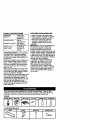
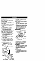
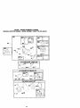
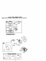
Owner's Manual
JCRAFTSMAN"
I
6.0 HP
26 INCH TINE WIDTH
FRONT TINE TILLER
WITH REVERSE
Model
No.
917.292490
•
•
•
•
•
•
Safety
Assembly
Operation
Maintenance
Espa_ol
Repair Parts
This product has a low emlsslon engine which operates
dlfferently from prevlously built englnea. Before you start
the englne, read and understand thls Owner's Manual.
CAUTION:
Read and follow all Safety
Rules and Instructions before
operating this equipment.
Sears, Roebuck and Co., Hoffman Estates, II 60179
Visit our Craftsman website:www.sears.corn/craftsman
Warranty
...............................................
2
Safety Rules .........................................
2
Product Specifications .......................... 4
Assembly ..............................................
6
Operation ..............................................
7
Maintenance .......................................
11
Maintenance Schedule ...................... 11
Service and Adjustments .................... 13
Storage ...................................... ._........ 16
Troubleshooting ................................. 17
Illustrated Parts List ............................ 38
Parts Ordering ..................... Back Cover
LIMITED TWO YEAR WARRANTY ON CRAFTSMAN TILLER
For two (2) years from date of purchase, when this Craftsman Tiller is maintained,
lubricated, and tuned up according to the operating and maintenance instructions in
the owner's manual, Sears will repair free of charge any defect in material or workmanship.
This Warrantydoes not cover:.
• Expendableitems whichbecome wornduring normal use, such as tines, spark
plugs,air cleaners and belts.
• Repairs necessary because of operatorabuse or negligence,includingbent
crankshaftsand the failure to maintainthe equipmentaccordingto the instructions
containedin the owner's manual.
• If this CraftsmanTilleris used for commercialor rental purposes,this Warranty
applies for only thirty(30) days from the date of purchase.
Warranty service is available by returning the craftsman power mower to the nearest
sears service center/department in the united states. This warranty applies only while
this product is in use in the united states.
This Warranty givesyou specificlegal rights, and you may also have otherrightswhich
vary fromstate to state.
SEARS, ROEBUCK AND CO., D/817WA, HOFFMAN
ESTATES, IL 60179
IMPORTANT:This cuttingmachineis capable of amputatinghands and feet and
throwingobjects. Failureto observethe following safety instructionscould resultin
serious injury or death.
TRAINING
• Read the Owner's Manual carefully. Be
thoroughly familiar with the controls
and the proper use of the equipment.
Know how to stop the unit and disengage the controls quickly.
• Never allow children to operate the
equipment. Never allow adults to
operate the equipment without proper
instruction.
• Keep the area of operation clear of all
persons, particularly small children,
and pets.
PREPARATION
• Thoroughly inspect the area where the
equipment is to be used and remove all
foreign objects.
• Disengage all clutches and shift into
neutral before starting the engine
(motor).
• Do not operate the equipment without
wearing adequate outer garments.
Wear footwear that will improve footing
on slippery surfaces.
• Handle fuel with care; it is highly
flammable.
• Use an approved fuel container.
• Never add fuel to a running engine or
hot engine.
• Fill fuel tank outdoors with extreme
care. Never fill fuel tank indoors.
• Replace gasoline cap securely and
clean up spilled fuel before restarting.
• Use extension cords and receptacles
as specified by the manufacturer for all
units with electric drive motors or
electric starting motors.
• Never attempt to make any adjustments
while the engine (motor) is running
(except where specifically recommended by manufacturer).
OPERATION
• Do not put hands or feet near or under
rotating parts.
• Exercise extreme caution when
operating on or crossing gravel drives,
walks, or roads. Stay alert for hidden
hazards or traffic. Do not carry passengers.
• After striking a foreign object, stop the
engine (motor), remove the wire from
the spark plug, thoroughly inspect the
tiller for any damage, and repair the
damage before restarting and operating the tiller.
• Exercise caution to avoid slipping or
falling.
• If the unit should start to vibrate
abnormally, stop the engine (motor)
and check immediately for the cause.
Vibration is generally a warning of
trouble.
• Stop the engine (motor) when leaving
the operating position.
• Take all possible precautions when
leaving the machine unattended.
Disengage the tines, shift into neutral,
and stop the engine.
• Before cleaning, repairing, or inspecting, shut off the engine and make
certain all moving parts have stopped.
Disconnect the spark plug wire, and
keep the wire away from the plug to
prevent accidental starting. Disconnect
the cord on electric motors.
• Do not run the engine indoors; exhaust
fumes are dangerous.
• Never operate the tiller without proper
guards, plates, or other safety protective devices in place,
• Keep children and pets away.
• Do not overload the machine capacity
by attempting to till too deep at too fast
a rate.
• Never operate the machine at high
speeds on slippery surfaces. Look
behind and use care when backing,
• Never allow bystanders near the unit.
• Use only attachments and accessories
approved by the manufacturer of the
tiller.
• Never operate the tiller without good
visibility or light.
• Be careful when tilling in hard ground.
The tines may catch in the ground and
propel the tiller forward. If this occurs,
let go of the handlebars and do not
restrain the machine.
MAINTENANCE
AND STORAGE
• Keep machine, attachments, and
accessories in safe working condition.
• Check shear pins, engine mounting
bolts, and other bolts at frequent
intervals for proper tightness to be sure
the equipment is in safe working
condition.
• Never store the machine with fuel in the
fuel tank inside a building where
ignition sources are present, such as
hot water and space heaters, clothes
dryers, and the like. Allow the engine to
cool before storing in any enclosure.
• Always refer to the operator's guide
instructions for important details if the
tiller is to be stored for an extended
period.
_Look for this symbol to point out
important safety precautions. It means
CAUTIONfff BECOMEALERTll!
YOUR
SAFETY IS INVOLVED.
ACAUTION: Always disconnect spark
plug wire and place wire where it cannot
contact spark plug in order to prevent
accidental starting when setting up,
transporting, adjusting or making repairs.
AWARNING:
Engine exhaust, some of its
constituents, and certain vehicle components contain or emit chemicals known to
the State of California to cause cancer
and birth defects or other reproductive
harm.
3
PRODUCT
SPECIFICATIONS
CUSTOMER
GASOLINE
CAPACITY:
3 QUARTS
UNLEADED
REGULAR
OIL (API-SFoSJ):
SAE 30
(ABOVE 32°F)
SAE 5W-30
(BELOW 32°F)
CHAMPION
RJ19LM OR
J19LM
CAPACITY: 20OZ.)
SPARK PLUG :
(GAP: .030")
RESPONSIBILITIES
• Read and observe the safety rules.
• Follow a regular schedule in maintaining, caring for and using your tiller.
• Follow the instructions under the
_Customer Responsibilities" and
"Storage" sections of this Owner's
Manual.
_WARNING:
This unit is equipped with
an internal combustion engine and
should not be used on or near any
unimproved forest-covered, brushcovered or grass covered land unless the
engine's exhaust system is equipped with
a spark arrester meeting applicable local
or state laws (if any). If a spark arrestar is
used, it should be maintained in effective
working order by the operator.
In the state of California the above is
required by law (Section 4442 of the
California Public Resources Code).
Other states may have similar laws.
Federal laws apply on federal lands. A
spark arrester for the muffler is available
through your nearest Sears service
center (See REPAIR PARTS section of
this manual).
CONGRATULATIONS on your purchase
of a Sears Tiller.It has been designed,
engineered and manufacturedto give
you the best possibledependabilityand
performance.
Shouldyou experience any problemsyou
cannot easily remedy,please contacta
Sears or other qualifiedService Center.
We have competent,well-trainedtechniciansand the propertoolsto service or
repair this unit.
Please read and retainthis manual. The
instructionswill enable you to assemble
and maintainyour tiller propedy.Always
observethe =SAFETY RULES".
Yournew tiller has been assembledat the
factory with exceptionof those parts left
unassembledfor shippingpurposes. To
ensuresafe and properoperationof your
tiller all parts and hardwareyou assemble must be tightenedsecurely.Use
the correcttools as necessaryto insure
proper tightness.
These accessories were available when the tiller was pumhased. They are also
available at most Sears Retail outlets and Service Centers. Most Sears Stores can
order repair parts for you when you provide the model number of your tiller.
ENGINE
IT] l l l
TILLER MAINTENANCE
BELT
TINES
SHEAR PIN
4
HAIRPIN CLIP
Your new tiller has been assembled at the
factory with exception of those parts left
unassembled for shipping purposes. To
ensure safe and proper operation of your
tiller all parts and hardware you assemble
must be tightened securely. Use the correct
tools as necessary to insure proper
tightness.
TOOLS REQUIRED FOR ASSEMBLY
Front
Left
Right
A socket wrench set will make assembly
easier. Standard wrench sizes are listed.
(1) Utility knife
(1) Screwdriver
(1) Pair of pliers
(2) 112" wrenches
OPERATOR'S POSITION
When right or left hand is mentioned in this
manual, it means when you are in the
operating position (standing behind tiller
handles).
CONTENTS
Operator's Position
OF HARDWARE
(1) Clevis Pin
(1) Manual
(1) Plastic
Cable
PACK
©
(1) Washer
9/32 x 1/2 x
14 Gauge
(2) Flange
Locknuts
5/16-18 UNC
Clip
(1) Cotter Pin
(2) Hex Bolts
5/16-18
©
©
x 1-1/4
(2) Hex Nuts
5/16-18
(2) Lock
Washers
5/16
(1) Reverse
Rod Bracket
(1) Bottle
Bushing
(_(1)
©
Engine Oil
i!i!i!i !ilii!i!i!il!lU
(2) Carriage Bolts
5/16-18
5
UNC x 2-1/2
UNPACK CARTON
_CAUTION:
Be careful of exposed
staples when handling or disposing of
cartoning material.
IMPORTANT: When unpacking and
assembling tiller, be careful not to stretch
or kink cable(s).
1. Cut cable ties securing handle column
and reverse rod.
2. Slide handle column onto handle
mount.
3. Remove all packing from carton.
ASSEMBLE HANDLE
1. Slide reverse rod through hole in
reverse rod bracket as shown.
2. Slide bushing over lower reverse rod
and snap into bracket hole.
NOTE: Make sure tine control cable is
routed in front of reverse rod bracket.
3. Attach reveres rod bracket to handle
column using two (2) carriage bolts
and two (2) flange Iocknuts and
tighten securely.
4. Cut away carton.
5. Insert plastic cable clip into hole in
handle column.
6. Route tine control cable through
plastic cable clip on handle column.
7. Cut cable ties securing tiller to skid.
Remove tiller from skid by pulling
backwards.
ASSEMBLE REVERSE ROD
H
..
Tine Control
and,eMou
Tine Control\
//_
oa,,a\
\ y
_ ._=_
_
"_
Handle Column
• Secure upper reverse rod to lower
reverse rod using clevis pin, washer
and cotter pin.
INSTALL DEPTH STAKE ASSEMBLY
1. Loosen nut "A".
2. Insert stake support between engine
bracket halves with stake spring
down,
3. Bolt stake support to engine brackets
with bolts, lock washers and nuts.
Tighten securely. Tighten nut "A".
4. Depth stake must move freely. If it
does not, loosen support bolt.
HANDLE
HEIGHT
Bracket Halves
Depth
Stake
Bolt
Spdng
Hex Bolts, Lock Washers,
and hex Nuts
• Handle height may be adjusted to
better suit operator. (See "HANDLE
HEIGHT" in the Service and Adjustments section of this manual).
TILLING WIDTH
• Tilling width may be adjusted to better
handle your tilling conditions (See
"FINE ARRANGEMENT" in the Service
and Adjustments section of this
manual).
TINE OPERATION
• Check line operation before first use.
(See "rlNE OPERATION CHECK" in
the Service and Adjustments section of
this manual).
Carriage L
/ / )_Cotter
Pin
Bolts.<_:_;% / / J _.._t,
Nasher
;_ ,
.
Upper
, < Revarsa
Rod
_:_',,._Clevis
Pin
_
_
"Bushing
Lower Reverse Rod
Flange Locknuts
Reverse
_
KNOWYOURTILLER
READ
THISOWNER'S
MANUAL
ANDSAFETY
RULES
BEFORE
OPERATING
YOUR
TILLER.
Compare the illustrations with your tiller to familiarize yourself with the location of
various controls and adjustments. Save this manual for future reference.
These symbols may appear on yourTiller
Learn and understand their meaning,
or in literature supplied with the producL
I
TLLII_G
FORI_*AFIO
NEUTRAL
REVE_q_E
CAUTION
B_INE
OR WARNING
ON
F_E
FA._I"
SLOW
C=*_KE
FU_L
OIL
FITOP
O
OFF
.Trs::ne
Oontro,
_
Choke Control
-.Throttle Control
_.--_
Tins Shield
?
Depth Stake _
•Tines
Recoil Starter Handle j
Sears tillersconformto the safety standardsof the
American NationalStandards Institute.
THRO'n'LE CONTROL - Controls engine
speed.
DEPTH STAKE - Controls forward speed
and the depth at which the tiller will dig.
RECOIL STARTER HANDLE - Used to
start the engine.
FORWARD TINE CONTROL - Engages
tines in forward direction.
REVERSE TINE CONTROL - Engages
tines in reverse direction.
CHOKE CONTROL - Used when starting
a cold engine.
7
The operation of any tiller can result in foreign objects
which can result in severe eye damage. Always wear
shields before starting your tiller and while tilling. We
vision safety mask over spectacles or standard safety
thrown into the eyes,
safety glasses or eye
recommend a wide
glasses.
HOWTO USEYOURTILLER
Knowhow to operateall controlsbefore
addingfuel and oil or attemptingto start
engine.
STOPPING
TINES
1. Release forwardtine controlto stop
forward movement.
2. Release reverse tine controlto stop
reverse movement.
ENGINE
• Move throttlecontrolto "STOP" position.
NOTE: Never use choke to stopengine.
The depth stake should always be below
the wheels for digging. It serves as a
brake to slow the tillers forward motion to
enable the tines to penetrate the ground.
Also, the more the depth stake is lowered
into the ground the deeper the tines will
dig.
Reverse Tine Control
Adjust wheels by removing the hairpin
clip and clevis pin. Change wheel
position. Replace the hairpin clip and
clevis pin.
• For normal tilling, set wheels at the
second or third hole from the top.
Forward Tine Control
_2+'A.+.,_.
si_ion
0
J/
._
DEPTH STAKE
Adjust depth stake by removing the
hairpin clip and clevis pin. Change depth
stake to desired position. Replace the
clevis pin and hairpin clip.
• For normal tilling, set depth stake at the
second or third hole from the top.
WHEELS
Forward Tine Control
"ON" (DOWN)
HairpinClip
and Clevis Pin
Position
Stake
Throttle
Control
Control
"lINE OPERATION
FORWARD
• Squeeze forward tine control to handle.
REVERSE
• With forward fine control "OFF" (up)
position, pull back and hold reverse
tine control.
TILLING
The speed and depth of tilling is regulated by the position of the depth stake
and wheel height.
Spring
HairpinClip
and ClevisPin
TO TRANSPORT
_CAUTION: Beforeliftingor transporting,
allowtiller engine and mufflerto cool.
Disconnectspark plug wire. Drain
gasolinefrom fuel tank.
AROUND THE YARD
1. Tip depth stake forward untilit is held
by the stake spring,
2. Push tiller handles down, raising tines
off the ground.
3. Push or pull tiller to desired location.
AROUND TOWN
1. Disconnectspark plug wire.
2. Drain fuel tank.
3. Transportin updghtpositionto
prevent oil leakage.
BEFORE STARTING ENGINE
IMPORTANT: Be very careful not to allow
dirt to enter the engine when checking or
adding oil or fuel, Use clean oil and fuel
and store in approved, dean, covered
containers, use clean fill funnels.
FILL ENGINE WITH OIL
1. Remove hangtag from engine.
2. With engine level, remove engine oil
filler plug.
3. Fill engine with oil to point of overflowing. For approximate capacity see
"PRODUCT SPECIFICATIONS" on
page 4 of this manual A_Ioil must
meet A.P.I. Service Classification SFSJ.
4. Tilt tiller back on its wheels and then
re-leve|.
5. With engine level, refill to point of
overflowing if necessary. Replace oil
filler plug.
• For cold weather operation you should
change oil for easier staffing (See "OIL
VISCOSITY CHART _ in the Maintenance section of this manual).
• To change engine oil, see the Maintenance section of this manual.
Oil L,
Plug
ADD GASOLINE
• Fill fuel tank. Use fresh, clean, regular
unleaded gasoline. (Use of leaded
gasoline will increase carbon and lead
oxide deposits and reduce valve life.)
IMPORTANT: When operating in tamperaturos below 32°F(0°C), use fresh,
clean, winter grade gasoline to help
insure good cold weather starting.
_I_WARNING: Expedence indicates that
alcohol blended fuels (called gasohol or
using ethanol or methanol) can attract
moisture which leads to separation and
formation of acids during storage. Acidic
gas can damage the fuel system of an
engine while in storage. To avoid engine
problems, the tuel system should be
emptied before storage of 30 days or
longer. Drain the gas tank, start the
engine and let it run until the fuel lines
and carburetor are empty. Use fresh fuel
next season, See Storage section of this
manual for additional information. Never
use engine or carburetor cleaner products in the fuel tank or permanent
damage may occur.
A, CAUTION: Fill to within 1/2 inch of top
of fuel tank to prevent spills and to allow
for fuel expansion. If gasoline is accidentaLLyspi_ed, move machine away from
area of spill. Avoid creating any source of
ignition until gasoline vapors have
disappeared.
Do not overfill. Wipe off any spilled oil or
fuel. Do not store, spill or use gasoline
near an open flame.
TO START ENGINE
4;I.CAUTION: Keep drive control bar in
"DISENGAGED" position when staffing
engine.
When starting engine for the first time or if
engine has run out of fuel, it will take
extra pulls of the recoil starter to move
fuel from the tank to the engine.
1. Make sure spark plug wire is properly
connected.
2. Place throttle control in "FAST"
position.
3. Move choke contro_to choke position.
4. Grasp recoil starter handle with one
hand and grasp tiller handle with
other hand. Pull rope out slowly until
engine reaches staff of compression
cycle (rope will pull slightly harder at
this point).
5. Pull recoil starter handle quickly. Do
not let staffer handle snap back
against staffer.
NOTE: If engine fires but does not start,
move choke control to half choke position.
Pull recoil starter handle until engine
starts.
6. When engine staffs, slowly move
choke control to "RUN" position as
engine warms up.
NOTE: A warm engine requires less
choking to staff.
7. Move throttle control to desired
running position.
8. Allow engine to warm up for a few
minutes before engaging tines.
NOTE: If at a high altitude (3000 feet) or
in cold temperatures (below 32°F), the
carburetor fuel mixture may need to be
adjusted for best engine performance.
See "TO ADJUST CARBURETOR" in the
Service and Adjustments section of this
manual.
NOTE: if engine does not start, see
troubleshooting
points.
9
: Plug
Soil conditions are important for proper
tilling. Tines will not readily penetrate
dry, hard soil which may contribute to
excessive bounce and difficult handling
of your tiller. Hard soil should be
moistened before tilling; however,
extremely wet soil will "ball-up" or
clump during tilling. Wait until the soil is
less wet in order to achieve the best
results. When tilling in the fall, remove
vines and long gross to prevent them
from wrapping around the tine shaft
and slowing your tilling operation.
You will find tilling much easier if you
leave a row untilled between passes.
Then go back between tilled rows.
There are two reasons for doing this.
First, wide turns are much easier to
negotiate than about-faces. Second,
the tiller won't be pulling itself, and
you, toward the row next to it.
Set depth stake and wheel height for
shallow tilling when working extremely
hard soil or sod. Then work across the
first cuts at normal depth.
Contml
Choke
Recoil
BREAKING
INYOURTILLER
Break-in your belt(s), pulleys and tins
control before you actually begin tilling.
• Start engine, tip tines off ground by
pressing handles down and engage
line control to start fine rotation. Allow
tines to rotate for five minutes.
• Check tine operation and adjust if
necessary. See "TINE OPERATION
CHECK" in the Service and Adjustments section of this manual.
TILLING
HINTS
_kCAUTION: Until you ere accustomed to
handling your tiller, start actual field use
with throttle in slow position (mid-way
between "FAST" and "IDLE").
To help tiller move forward, lift up the
handles slightly (thus lifting depth stake
out of ground). To slow down the tiller,
press down on handles.
If you are straining or tiller is shaking, the
wheels and depth stake are not set
properly in the soil being tilled. The
proper setting of the wheels and depth
stake is through trial and error and
depends upon the soil condition. (The
harder or wetter the ground, the slower
the engine and tine speed needed. Under
these poor conditions, at fast speed the
tiller will run and jump ever the ground).
A propedy adjusted tiller will dig with little
effort from the operator.
• Tilling is digging into, turning over, and
breaking up packed soil before
planting. Loose, unpacked soil helps
root growth. Best tilling depth is 4" to
6". A tiller will also clear the soil of
unwanted vegetation. The decomposition of this vegetable matter enriches
the soil, Depending on the climate
(rainfall and wind), it may be advisable
to till the soil at the end of the growing
season to further condition the soil.
CULTIVATING
Cultivating is destroying the weeds
between rows to prevent them from
robbing nourishment and moisture from
the plants. At the same time, breaking up
the upper layer of soil crust will help
retain moisture in the soil. Best digging
depth is 1" to 3".
• You will probably not need to use the
depth stake. Begin by tipping the depth
stake forward until it is held by the
stake spring.
• Cultivate up and down the rows at a
speed which will allow tines to uproot
weeds and leave the ground in rough
condition, promoting no further growth
of weeds and grass.
10
I
MAINTENANCE
SCHEDULE
FILL IN DATES
AS YOU COMPLETE
REGULAR SERVICE
SERVICE DATES
Check EngineOil Level
v'
v'
t/
OilPivotPoints
=/
Inspect Spark Arrester / Muffler
i/
Inspect Air Screen
CleanorReplace
AirCleanerCartridge
Clean Engine Cylinder
Fins
v'
v'
Replace Spark Plug
1 - Change mote olten whe,1 operating under a heavy load or in high amldent teml:_ratures.
2 - SeP4tcemore often whan 0t0eratlr_ II1dirtyor dUstyco:ldltlc_s.
LUBRICATION CHART
GENERAL
RECOMMENDATIONS
The warranty on this tiller does not cover
items that have been subjected to
operator abuse or negligence. To receive
full value from the warranty, the operator
must maintain tiller as instructed in this
manual.
Some adjustments will need to be made
periodically to properly maintain your
tiller.
All adjustments in the Service and
Adjustments section of this manual
should be checked at least once each
;line
*
** Er
season.
• Once a year you should replace the
spark plug, clean or replace air filter,
and check tines end belts for wear. A
new spark plug and clean air filter
assure proper air-fuel mixture and help
your engine run better and last longer.
BEFORE EACH USE
v
_._'_
1. Check engine oil level.
2. Check tine operation.
3. Check for loose fasteners.
* Idle
LUBRICATION
SAE 30 OR 10W30 MOTOR OIL
** REFER TO MAINTENANCE "ENGINE "
SECTION.
Keep unit well lubricated (See "LUBRICATION CHART").
11
ml
_,CAUTION:
Disconnect spark plug wire
before performing any maintenance
(except carburetor adjustment) to prevent
accidental starting of engine.
Prevent fires! Keep the engine free of
grass, leaves, spilled oil, or fuel. Remove
fuel from tank before tipping unit for
maintenance. Clean muffler area of all
grass, dirt, and debris.
Do not touch hot muffler or cylinder fins
as contact may cause bums.
ENGINE
LUBRICATION
Use only high quality detergent oil rated
with API service classification SF-SJ.
Select the oil's SAE viscosity grade
according to your expected temperature.
L
__SAE
VISCOSITY
(3RAD£S
NOTE: Although multi-viscosity oils (5W30, 10W-30, etc.) improve starting in cold
weather, these multi-viscosity oils will
result in increased oil consumption when
used above 32°F (0°C). Check your
engine oil level more frequently to avoid
possible engine damage from running
low on oil.
Change the oil after every 50 hours of
operation or at least once a year if the
tiller is not used for 50 hours in one year.
Check the crankcase oil level before
starting the engine and after each five (5)
hours of continuous use. Add SAE 30
motor oil or equivalent. Tighten oil filler
plug securely each time you check the oil
level.
Plug\
,,_1_ "Oil
__.J
Filter
Plug
AIR CLEANER
Service air cleaner cartridge every
twenty-five hours, more often if engine is
used in very dusty conditions.
1. Loosen air cleaner screw.
2. Remove air cleaner cover.
3. Carefully remove air cleaner cartridge.
Be careful. Do not allow dirt or debris
to fall into carburetor.
4. Clean by tapping gently on a flat
surface.
NOTE: If very dirty or damaged, replace
cartridge.
5. Clean and replace cover. Tighten
screw securely.
_CAUTION:
Petroleum solvents, such as
kerosene, are not to be used to clean
cartridge. They may cause deterioration
of the cartridge. Do not oil cartridge. Do
not use pressurized air to clean or dry
cartridge.
Cover
Air
Cleaner
TO CHANGE ENGINE OIL
Determine temperature range expected
before oil change. All oil must meet API
service classification SF-SJ.
• Be sure tiller is on level surface.
• Oil will drain more freely when warm.
• Catch oil in a suitable container.
1. Remove drain plug.
2. Tip tiller forward to drain oil.
3. After oil has drained completely,
replace oil drain plug and tighten
securely.
4. Remove oil filler plug. Be careful not
to allow dirt to enter the engine.
5. Refill engine with oil. See "FILL
ENGINE WITH OIL" in the Operation
section of this manual.
COOLING SYSTEM
Your engine is air cooled. For proper
engine performance and long life keep
your engine clean.
• Clean air screen frequently using a
stiff-bristled brush.
• Remove blower housing and clean as
necessary.
• Keep cylinder fins free of dirt and chaff.
12
Muffler
SPARK PLUG
r Fins
Replace spark plugs at the beginning of
each tilling season or after every 50
hours of use, whichever comes first.
Spark plug type and gap setting are
shown in "PRODUCT SPECIFICATIONS"
on page 4 of this manual.
TRANSMISSION
Housing
Your transmission is sealed and will not
require lubrication unless serviced.
CLEANING
MUFFLER
Do not operate tiller without muffler. Do
not tamper with exhaust system. Damaged mufflers or spark arresters could
create a fire hazard. Inspect periodically
and replace if necessary. If your engine is
equipped with a spark arrester screen assembly, remove every 50 hours for cleaning and inspection. Replace if damaged.
Do not clean your tiller when the engine
and transmission are hot. We do not
recommend using pressurized water
(garden hose, etc.) to clean your unit
unless the gasket area around the
transmission and the engine muffler, air
filter and carburetor are covered to keep
water out. Water in engine will shorten
the useful life of your tiller.
• Clean engine, wheels, finish, etc. of all
foreign matter,
• Keep finished surfaces and wheels free
of all gasoline, oi!, etc.
• Protect painted surfaces with automotive type wax.
TINE ARRANGEMENT
Your outer tines can be assembled in
several different ways to suit your tilling or
cultivating needs.
_CAUTION:
Tines are sharp. Wear
gloves or other protection when handling
tines.
_I, CAUTION: Disconnect spark plug wire
from spark plug and place wire where it
cannot come into contact with plug.
TILLER
TO ADJUST HANDLE HEIGHT
Factory assembly has provided lowest
handle height. Select handle height best
suited for your tilling conditions. Handle
height will be different when tiller digs
into soil.
1. If a higher handle height is desired,
loosen the four nuts securing handle
panel to engine brackets.
2. Slide handle panel to desired location.
3. Tighten the four nuts securely.
NORMAL TILLING - 26" PATH
• Assemble holes =A" in tine hubs to
holes "B" in tine shaft.
_--
Clevis Pin
Outer
7
Engine Brackets
HairpinClip
andle Panel
MID-WIDTH TILLING - 24" PATH
• Assemble holes "A" in tine hubs to
holes "C" in tine shaft.
Nuts(Also 2
o_llLt:r Side
13
NARROW TILLING/CULTIVATING
12-3/4" PATH
• Remove outer tines.
Ioo
-
NOTE: If "ON" position check required
adjustment, recheck "OFF" position
adjustment to insure tines do not rotate
when control is "OFF" (up).
i
Tine Control"OFP
--ooWl
I u //
Inner Tines On
Cable Clip._..__. i i Tin_._ntrol Cable
NOTE: When reassemblin outer tines,
be sure right fine assembl' ' (marked "R")
and left tine assembly (marked %") are
mounted to correct side of tine shaft.
TINE OPERATION CHECK
AWARNING:
Disconnect spark plug wire
from spark plug to prevent starting while
checking tine operation.
For proper tine operation, forward tine
control lever must be against control body
and all slack removed from inner wire of
control cable when control is in the "OFF"
(up) position.
If lever and cable are loose, loosen cable
clip at lower end of cable. Pull up on
cable to remove slack, without extending
spring on end of cable, and retighten
cable clip.
FINAL CHECK "OFF" POSITION
1. With tine control "OFP (up), push
down on handle to raise tines off the
ground.
2. Slowly pull recoil starter handle while
observing tines. Tines should not
rotate.
3. If tines rotate, inner wire of control
cable is too tight which is extending
lower spdng and engaging tines.
Loosen cable clip and push down on
cable only enough to relieve spring
tension. Tighten cable clip.
4. Recheck in "OFF" position and adjust
if necessary.
FINAL CHECK "ON" POSITION
5. With tine control "ON" (held down to
handle) push down on handle to raise
tines off the ground.
6. Slowly pull recoil starter handle while
observing tines. Tines should rotate
forward.
7. If tines do not rotate, inner wire of
control cable is too loose. Loosen
cable clip and pull cable up to remove
slack and retighten clip.
8. Recheck in "ON" position and adjust if
necessary.
14
Tine.Control
"ON_ Position
TO REMOVE BELT GUARD
I.
Remove two (2) cap nuts and washers from side of belt guard.
2. Loosen (do not remove) tine shield
nut on underside of tine shield.
3. Pull belt guard out and away from
unit.
4. Replace belt guard by reversing
above procedure. Be sure slot in
bottom of belt guard is under head of
fine shield bolt and all nuts are
tightened securely.
_-_
_
_
_ Cap Nuts and
/Washer
_'-Tine
_Belt
Shield Nut
Guard
TO REPLACE V-BELTS
Replace V-belts if they have stretched
considerably or if they show cracks or
frayed edges. There are two (2) V-belts forward (inside) and reverse (outside).
1. Belt guard must be removed to service
belts. See "TO REMOVE BELT
GUARD" in this section of manual.
NOTE: Observe carefully routing of both
belts and location of all belt guides before
removing belts.
BELT REMOVAL
2. Remove reverse idler pulley from idler
arm,
3.
Remove reverse (outside) V-belt.
4. Remove forward (inside) V-belt from
transmission pulley first and then from
engine pulley.
BELT REPLACEMENT
5. Install new forward (inside) V-belt to
engine pulley first then to transmission
pulley. Be sure belt is positioned on
inside groove of both pulleys, inside
all belt guides and rests on idler
pulley.
6. Before installing reverse (outside) Vbelt, turn belt "inside out". Twist so
wide, flat surface of belt is to inside.
7. Wrap V-belt around reverse idler
pulley and reassemble idler to idler
arm, Tighten securely. Be sure belt is
between reverse idler
pulley and idler
arm pin.
8. Install belt to outside groove of
transmission pulley. Be sure belt is
inside all belt guides and rests on
outside groove of engine pulley.
CHECK TINE OPERATION
9. See 'TINE OPERATION CHECK" in
this section of manual.
10. Replace belt guard.
FRONT VIEW REFERENCE
Reverse
FORWARD MOTION (INSIDE)V-BELT
Rev£:
Reverse Idler Arm Reverse
Pulley
Belt Guard
Bolt
Idler Pulley
Maintenance, repair, or replacement of
the emission control devices and systems, which are being done at the
customers expense, may be performed
by any non-road engine repair establishment or individual. Warranty repairs must
be performed by an authorized engine
manufacturer's service outlet.
TO ADJUST CARBURETOR
The carburelor has been preset at the
factory and adjustment should not be
necessary. However, engine performance can be affected by differences in
fuel, temperature, altitude or load. If the
carburetor does need adjustment, contact
your nearest authorized service center/
department
IMPORTANT: Never tamper with the
engine governor, which is factory set for
proper engine speed. Overspeeding the
engine above the factory high speed
setting can be dangerous. If you think the
engine-governed high speed needs
adjusting, contact your nearest sears or
other qualified service center which has
the proper equipment and expedenoe to
make any necessary adjustments.
Foi:ward_
/
Idler
"_
J
Pulley
Tra/ns_on
Pulley
REVERSE (OUTSIDE) V-BELT
Reverse Idler Pulley
Engin_
j
_
0
Transmission
Pulley
ENGINE
Belt Guide
Forward_
Idler Pulley
V-Belt
Idler
y
Po,ey"
,'-',
(OUTSIDE)
Reverse
Idler
)
/
15
Immediately prepare your tiller for storage
at the end of the season or if the unit will
not be used for 30 days or more.
_kCAUTION: Never store the tiller with
gasoline in the tank inside a building
where fumes may reach an open flame or
spark. Allow the engine to cool before
storing in any enclosure.
TILLER
1. Clean entire tiller (See "CLEANING" in
the Maintenance section of this
manual).
2. Inspect and replace belts, if necessary
(See belt replacement instructions in
the Service and Adjustments section
of this manual).
3. Lubricate as shown in the Maintenance section of this manual.
4. Be sure that all nuts, bolts and screws
are securely fastened. Inspect moving
parts for damage, breakage and wear.
Replace if necessary.
5. Touch up all rusted or chipped paint
surfaces; sand lightly before painting.
ENGINE
FUEL SYSTEM
IMPORTANT: It is important to prevent
gum deposits from forming in essential
fuel system parts such as the carburetor,
fuel filter, fuel hose, or tank during
storage, also, experience indicates that
alcohol blended fuels (called gasohol or
using ethanol or methanol) can attract
moisture which leads to separation and
formation of acids during storage. Acidic
gas can damage the fuel system of an
engine while in storage.
1. Drain the fuel tank.
2. Start the engine and let it run until the
fuel lines and carburetor are empty.
• Never use engine or carburetor cleaner
products in the fuel tank or permanent
damage may occur.
• Use fresh fuel next season.
NOTE: Fuel stabilizer is an acceptable
alternative in minimizing the formation of
fuel gum deposits during storage. Add
stabilizer to gasoline in fuel tank or
storage container. Always follow the mix
ratio found on stabilizer container. Run
engine at least 10 minutes after adding
stabilizer to allow the stabilizer to reach
the carburetor. Do not drain the gas tank
and carburetor if using fuel stabilizer.
ENGINEOIL
Drain oil (with engine warm) and replace
with clean oil. (See "ENGINE" in the
Maintenance section of this manual).
C_(LtNDER
1. Remove spark plug.
2. Pour 1 ounce (29 ml) of oil through
spark plug hole into cylinder.
3. Pull starter handle slowly several
times to distribute oil
4. Replace with new spark plug.
OTHER
• Do not store gasoline from one season
to another.
• Replace your gasoline can if your can
starts to rust. Rust and/or dirt in your
gasoline will cause problems.
• If possible, store your unit indoors and
cover it to give protection from dust and
dirt.
• Cover your unit with a suitable protective cover that does not retain moisture.
Do not use plastic. Plastic cannot
breathe which allows condensation to
form and will cause your unit to rust.
IMPORTANT: Never cover tiller while
engine and exhaust areas are still warm.
1R
PROBLEM
Willnotstart
CAUSE
CORRECTION
1. Out of fuel,
2, Engine not "CHOKED"
properly.
3. Engine flooded.
4. Dirty air cleaner.
5. Water in fuel.
6. Clogged fuel tank.
7. Loose spark plug wire.
8. Bad spark plug or
improper gap.
9. Carburetor out of adjustment.
10.Oil soaked air filter.
Hardtostart
1. Throttle control not set
properly.
2. Dirty air cleaner.
3.
4.
Bad spark plug or
improper gap.
Stale or dirty fuel.
5. Loose spark plug wire.
6, Carburetor out of adjustment.
Lossofpower
1. Engine is overloaded.
2. Dirty air cleaner.
3. Low oil level/dirty oil.
4. Faulty spark plug.
5. Oil in fuel.
6. Stale or dirty fuel.
7. Water in fuel.
8, Clogged fuel tank.
9. Spark plug wire loose.
10.Dirty engine air screen.
11 .Dirty/clogged muffler.
12,Carburetor out of adjutsment,
13.Poor compression,
17
1. Fill fuel tank.
2. See =TO START ENGINE" in
the Operation section.
3. Wait several minutes before
attempting to start.
4. Clean or replace aircleaner
cartridge.
5. Drain fuel tank and carburetor, and refill tank with fresh
gasoline.
6, Remove fuel tank and clean.
7. Make sure spark plug wire is
seated pmperiy on plug.
8. Replace spark plug or adjust
gap.
9. Make necessary adjust
ments.
10. Replace air filter.
1. Place throttle control in
"FAST" position.
2. Clean or replace air cleaner
cartridge.
3. Replace spark plug or adjust
gap.
4, Drain fuel tank and refill with
fresh gasoline.
5. Make sure spark plug wire is
seated properly on plug.
6. Make necessary adjust
ments.
1. Set depth stake and wheels
for shallower tilling,
2. Clean or replace aimleaner
cartridge.
3. Check oil level/change oil.
4. Clean and regap or change
spark plug.
5. Drain and clean fuel tank
and refill, and clean carbure
tor.
6. Drain fuel tank and refill
with fresh gasoline.
7. Drain fuel tank and carburetor, and refill tank with fresh
gasoline.
8. Remove fuel tank and clean.
9. Connect and tighten spark
plug wire,
10.Clean engine air screen.
11.Clean/replace muffler.
12.Make necessary adjustments.
13.Contact a Sears or other
qualified sen/ice center.
PROBLEM
Engine
overheats
CAUSE
1. Lowoil level/dirty
oil.
2. Dirty engine air screen.
3. Dirty engine.
4. Partially plugged muffler.
5. Improper carburetor
adjustment,
CORRECTION
1. Check oil leveVchange oil.
2. Clean engine air screen.
3. Clean cylinder fins, air
screen, muffler area.
4. Remove and clean muffler.
5. Adjust carburetor to richer
position.
Excessive
bounce/difficult
handling
1. Ground too dry and hard.
1. Moisten ground or wait for
more favorable soil conditions.
Soil balls up or
clumps
1. Ground too wet,
1. Wait for more favorable
soil conditions.
Engine runs but
tiller won't
move
1. Tins control is not
engaged.
2. V-belt not correctly
adjusted.
3. V-belt is off pulley(s).
1. Engage tine control.
Engine runs but
labors when
tilling
t.
Tilling too deep.
2. Throttle controlnot
properly adjusted.
3. Carburetorout of
adjustment.
2. InspecVadjust V-belt.
3. Inspect V-belt.
1. Set depth stake for shallower
tilling.
2. Check throttle control setting.
3. Make necessary adjust
ments.
Tines Skip
over ground
t. Shear pin (s) broken.
1. Replace shear pin(s).
Hard to Shift
into gear
1. Gears not timmed.
1. Brieflyengage drivecontrol
bar and release or rock tiller
forward and backwarduntil
are able to shiftgears.
Tiller shuts off
when drive
control bar
engaged
I. Shift lever set in between
counter rotating till position and forward rotating
till position.
2. Tines jammed.
f.
Shift to either counter
rotating till position or
forward rotating
till position.
2. Clear tines.
TILLER -- MODEL NUMBER 917.292490
HANDLES
3$
17
42
29
19
35
22
23
14
13
12
KEY PART
NO. NO.
DESCRIPTION
1
3
12
13
14
17
18
19
20
21
22
23
24
25
Panel, Control
Gdp, Handle
Nut, Flange
Bolt, Cardage 5/16-18 x 3/4
Assembly, Panel and Tube
Knob, Control, Reverse
Cable, "line Control
Lever, Control, Tine
Pin, Pivot
Ring, Clip
Reverse Rod, Upper
Pin, Retaining
Reverse Rod, Lower
Washer 13/32 x 13/16 x 10 Ga.
136993
11_32X
98G00129
STD533107
11(_14x
106932X
3066J
151229
1548(_
12000027
101248K
1778E
137(_6
STO551037
KEY
NO,
PART
NO.
DESCRIPTION
26
27
29
35
36
37
38
39
40
41
42
STD561210
STD560907
12000059
72010620
7397(T_00
165197
152094
137640
136998
STD551(][25
139907
Pin, Cotter I/8 x 3/4
pin, Colter 3/32 x 112
Retaining Ring
Bolt 5/16-18 X 2-I/2
Locknut, Range 5/16-18 UNC
Clip, Cable
Assembly, Handle Column
Bu6Nng, Reverse Rod Bracket
Bracket, Reverse ROd
Washer 9F32x1/2x14Gauge
Grommet
NOTE: All component dimensions given in U.S. inches.
1 inch = 25.4 mm
38
TILLER - - MODEL NUMBER 917.292490
BELT GUARD AND PULLEY ASSEMBLY
29
10
11
12
16
KEY
NO.
PART
NO.
1
2
3
175369
9484R
86777
4
5
6
7
8
9
10
11
12
13
14
15
16
17
18
74610812
STD541037
STD5510_7
2009J
175558
74760628
1567_X558
STD551025
104213X
72140406
1330_5
2614J
12000(_5
2649M
151236
DESCRIPTION
Assembly, Bracket, Belt Guard
Clip, Cable
Screw, Hex Washer lld+ Slotted,
Thrd cut. #10-24 x 1/2 Type D
Bolt, Hex Head 1/2-20 x 3/4
Nut, Hex 3_-16
Washer 13/32 x 13/16 x 16 Ga.
Pulley, Idler, Reverse
Assembly Ann Reverse Idler
Bo_t, Hex Hd 3/B-16 x 1-3/4
Guard, Belt
Washer 9/32 x 5/8 x 16 Ga.
Nut, Cap 1/4-20
Bolt, Carriage 1/4-20 x 3/4
VoBell (Fonvard Motion)
V-Belt (Reverse)
Ring, Retainer
Key, Square
Sheave, Transmission, fiat
KEY
NO.
PART
NO.
19
20
21
22
23
24
25
26
27
28
29
30
165914
12_O0036
STD541237
161806
175377
S_12
t 06968X
_
STD541(_.5
541_5
109227X
2"3200404
31
32
35
40
I01189L
151223
19091416
STD541425
DESCRIPTION
Bolt, Belt Guard
Ring, KIIp
Nut, Hex, Jam 3/6-16
Pulley, Idler
Arm, Idler
Bolt, Hex Head 3/8-16 x 1-1/4
Shalt, Idler Arm
Nut, Hex, Jam 5/16-18
Nut, Hex 1/4-20
Washer, Lock 1/4
Pad, Idler
Screw Set Socket, Headless
C.P. 1/4-20 x 1/4
Sheave, Engine
Sheave,Transmisison
Washer 9/32 x 7/8 x 16 Ga.
Nut 114-20
NOTE: All Component din_ension$ given in U.S.
inches. 1 inCh = 25.4 mm
TILLER - - MODEL NUMBER 917.292490
WHEEL AND DEPTH STAKE ASSEMBLY
7
6
7
17
19 2O
19 1
17
KEY
NO,
PART
NO.
DESCRIPTION
1
2
3
4
5
6
7
8
9
10
11
13
9194R
74_
STD523107
STD541(_G1
STD551131
STD541437
4921H
1952J
12_o33X
326J
74780628
1951J
Pin, Clevis
Bolt, Hex Head 5/16-18 x 1-1/4
Bolt, Hex Head 5/,1_-16 x 3/4
Nut, Hex 5/16-18
Washer, Lock 5/16
Locknut, whvasher 5/8-16
Clip, Helrpln
Support, Depth Stake, R.H.
Stake, Depth
Pth, Clevis
Bolt, Fin, Hex 3/8-16 x 1-3/4
Support, Depth Stake, L.H.
KEY
NO.
PART
NO.
DESCRIPTION
15
16
17
18
19
20
21
22
5388J
121117X
9188R
STD551(_7
91g0R
STD541437
74760516
$1_o41431
Spdng, Stake
Bolt, Shoulder
VWleel
Washer 13i32x13/16x11Ga.
Bracket, Wheel
Locknut, Crown 3/8-16
Bolt, Hex Head 5/1 6-18 x 1
Locknut, w/Insert 5/16-18
NOTE: All componentdlmenslonsgivenIn U.S. Inches.
1 Inch= 25.4 mm
4O
TILLER - - MODEL NUMBER 917.292490
TINE ASSEMBLY
2
KEY
NO.
PART
NO.
DESCRIPTION
KEY PART
NO. NO.
DESCRIPTION
I
2
3
156934
STD_24006
1569"32
Tine, Outer, R.H.
Retalner Spllng
Tlne, Inner, R.H.
4
5
6
Tine, inner, L.H.
T_ne, Outer, L.H.
pin, Clevis
15_)31
156933
4929H
TILLER - - MODEL NUMBER 917.292490
TRANSMISSION
11
7
_.
12
KEY
NO.
PART
NO,
DESCRIP'nON
1
2
3
5
6
7
8
11
12
14
15
7476G524
S'fD523732
STD551037
$11To41437
9057R558
165835
1948J
74760544
176112
9173R
7397(To(_
Bolt, Hex 5/16-18 x 1-1/2 Gr. 2
Bolt, Fin, Hex 3/8-16 x 3-1/4
Washer 13/32 x 13/16 x 11
Locknut, wNtasher 3/8-16
Shleld,_ne
Bracket, Engine, R,H.
_racket, Engine, L.H.
Bolt, Hex Head 5/16-18 x 2-_4
Tmr_mlsslon
Spacer, Split
Nut, Hex, Keps 3/16-18 UNC
KEY
NO.
PART
NO.
16
17
18
19
20
19091412
19092016
STt_o51125
74610412
......
DESCRIPTION
Washer 9/32 x 7/8 x 12 Gauge
Washer 9F32 x 1-1/4 x 16 Ga.
Washer, Lock 1/4
Bolt, Hex 1/4-28 x 3/4 Grade 5
Engfne, (See Breakdown) Bdggs
Model No. 1t 0402-0206-E!
NOTE: All component dimensions given in U.S.
inches. 1 Inch = 25.4 mm
42
TILLER - - MODEL NUMBER 917.292490
DECALS
10
7
2
KEY
NO.
PART
NO.
DESCRIPTION
I
2
3
4
5
6
7
8
9
10
- -
176943
176941
166131
137653
120431X
176783
171078
120075X
182215
167156
176859
Decal, Cntd. Pnl Ser
Decal, Belt Grd
Decal, Logo
Decal, CauUon, "gne Coat rol
Decal, Hand Placemen!
Decal, Engine OperaUoa
Decal, Rewind Intek
Decal, Warning, Rotating Tines
Decal, Tkle Shield
Decal, B & S Intek
ManuaJl Owner's(EngiSpan)
TILLER - - MODEL NUMBER 917.292490
BRIGGS & STRATTON ENGINE- MODEL NUMBER 110402,TYPE NO. 0206-E1
51
993
307
24 _
22_
:_
21_._
o
"k REQUIRESSPECIALTOOLS'
TO IN_TALL SEE REPAIR
742_
INSTRUCTIONMANUAL.
_>_
11058 OWNER'S MANUAL
_)-
_-_.
_,_
_
44
_
32A _
TILLER- - MODEL NUMBER 917.292490
BRIGGS & STRATTON ENGINE - MODEL NUMBER 110402,TYPE NO. 0206-E1
lO4"_
633r_
365 :,:,'i,_,
I
975_
_,
137 I_
276 I+_
®
_td-j
977 CARBURETOR
GASKET SET
276
?_
51 _/,:_
I
___:=
633A ,_,
121 CARBURETOR
IlM. :+ 127+'_
633r_j
-
633 _
OVERHAUL
KIT
633Ar_
358 ENGINE GASKET SET
20
:_ ..
+_
I°_i
' _:'\1211
_
993
:'_,
"_
TILLER - - MODEL NUMBER 917.292490
BRIGGS & STRATTON ENGINE - MODEL NUMBER 110402,TYPE NO. 0206-E1
-_J 562%
_'
2221
505 _
427
836A_
" _-_i_-._ e2+_
r.
883
968
161
334
163
46
%
_i_
_++'_'_
ill
,'
i,
|
+
TILLER - - MODEL NUMBER 917,292490
BRIGGS & STRAI-rON ENGINE - MODEL NUMBER 110402,TYPE NO. 0206-E1
__
_, _
1211!_
J1036 EMISSIONS
6o_
-_
_ _/ 592
"--459_/_
LABEL
[
23
934_
48
1095 VALVE GASKET SET
A7
TILLER - - MODEL NUMBER 917.292490
BRIGGS & STRATrON ENGINE - MODEL NUMBER 110402,TYPE NO. 0206-E1
KEY
NO.
1
3
5
7
11
12
13
15
16
18
20
21
22
23
24
25
26
27
28
29
30
32
32A
33
34
35
36
40
45
46
48
51
55
58
60
65
95
97
98
PART
NO.
DESCRIPTION
693811
Cylinder Assembly
299819
• Seal-Oil (Magneto Side)
693643
Head-Cylinder
695166 -+ Gasket-Cylinder Head
692600
Tube-Breather
692549
• Gasket-Crankcase
691137
Screw (Cylinder Head)
691686
Plug-O, Drain
693797
Crankshaft
694466
Cover-Crankcase
692550
• SeaI-OIl(PTO Side)
281658
Cap-Oil Fill
691662
Screw (Engine Sump)
692987
Flywheel
222698
Key- Flywheel
690021
Piston Assembly (Standard)
694167
Piston Assembly (.010 _ O.S.)
694168
Piston Assembly (.020" O.S.)
694169
Piston Assembly (.030" O.S.)
499631
Ring Set-Piston (Standard)
692785
Ring Set-Piston (.010" O.S.)
692786
Ring Set-Piston (,020"O.S.)
692787
Ring Set-Piston .030" O,S.)
691866
Lock-Piston Pn
499423
Pin-Piston
499424
Rod-Connecting
692562
Dipper-Connecting Rod
691664
Screw (Connecting Rod)
695759
Screw(ConnecUng Rod)
499642
Valve-Exhaust
499641
Valve-Intake
691304
Spring-Valve Intake)
691304
Spring-Valve (Exhaust)
692194
Retainer-Valve
690977
Tappet-Valve
693404
Camshaft
Shod Block (Replacement
Engine)
692555. _._+ Gasket-Intake
691421
Housing-Rewind Stader
692259
Rope-Starter (Cut to
Required Length)
281434
Gdp-Stader Rope
690837
Screw (Rewind Starter)
691636
Screw (Throttle Valve)
690024
Shaft-Threttle
398185
Kit-Idle Speed
KEY
NO.
104
108
109
117
121
122
125
127
130
133
134
137
146
155
161
163
186
187
188
189
190
209
209A
219
220
222
227
238
271
276
281
300
PART
NO.
DESCRIPTION
691242
_1 Pin-Float Hinge
692567
Valve-Choke
690023
Shaft-Choke
694975
Jet-Main (Standard)
695157
Kit-Carburetor Overhaul
693749. O Spacer-Carburetor
696065
Carburetor
691739
G Plug-Welch
691181
Valve-Throttle
398187
FIoat-Carburator
398188
O Kit-Needle/Seat
693981 _:_ Gasket-Float Bowl
690979
Key-Timing
695882
Plate-Cylinder Head
696063
Base.Air Cleaner
696024
Gasket-Air Cleaner
692317
Connector-Hose
693401
Line-Fuel (Motded)
690877
Screw Contro_ Bracket)
694543
Sa -Rocker Arm
692127
Screw (Fuel Tank)
691278
Spring-Governor
692571
Spring-Governor
693578
Gear-Governor
691724
Washer (Governor Gear)
694253
Bracket-Control
692573
Control Lever-Governor
691300
Cap-Valve
694256
Lever-Control
271716 _:1: Sealing Washer
694252
Panel-Control
693593
Muffler
696066
Housin -Slower
306304693610
Shield-_-_linder
307
690345
Screw (Cylinder Shield)
RPM Settings:Low Speed: 1900-2100
High Speed: 3000-3200
•
Included in Engine Gasket Set, Key. No.
358
(_
Included in Carburetor OverhaulKit, Key.
NO. 121
:_
Included in Carburetor Gasket Set, Key.
No. 977
+
Included in Valve Gasket Set, Key, No.
1095
NOTE: All component dimensions given In U.S.
inches linch = 25.4 mm
48
TILLER -- MODEL NUMBER 917.292490
BRIGGS & STRATTON ENGINE - MODEL NUMBER 110402,TYPE NO. 0206-E1
KEY
NO,
332
333
334
337
356
356
363
365
383
415
425
427
445
455
456
459
504
505
552
562
592
597
601
608
613
615
615
619
621
632
PART
NO.
690662
692605
691061
491055
692390
695155
19069
692568
19374
693463
692583
694255
491588
692591
692299
281505
694254
691251
692346
691112
690800
691696
95162
497680
691665
692576
692547
691108
692310
693408
KEY
NO.
742
746
773
830
832
836
836A
851
868
883
914
914A
957
968
971
972
975
977
993
1005
1019
1022
1023
1026
1029
1034
1036
1058
1095
1162
1210
DESCRIPTION
Nut (Flywheel)
Armature-Magneto
Screw (Armature Magneto)
Spark Plug
Wire-Stop
EngleeGasket
Set
Flywheel Puller
Screw (Carburetor)
Wrench-Spark Plug
Plug
Screw (Air Cleaner Cover)
Nut Control Bracket)
F ter-Air Ceaner Cartridge
Cup-Flywheel
Plate-Pawl Fdctlen
PawI-Ratchet
Washer Set
Nut (Governor Control Lever)
Bushtng-Govemor Crank
Bolt (Governor Control Lever)
Nut (Rewind Starter
Screw (Pawl Fdctlen Plate)
Clamp-Hoee
Starter-Rewind
Screw(Muffler)
Retainer-Governor Shaft
Crank-Governor
Screw (Cylinder Head Plate)
Switch-Stop
Spring/Link-Mechanical
Governor
633 693867 _1: Seal-Choke/Throttle Shaft
633A 691321 _:_ Seal-Throttle Shaft
663
635
668
676
677
689
692
718
741
694593
692076
694257
393757
690661
691855
690572
690959
692565
PART
NO.
692564
692566
694258
694544
693583
690661
693624
493880
692044
691893
692198
692557
694261
692584
690370
694260
493640
695156
691892
692592
694851
691890
499924
693517
691230
691343
695041
274263
695289
692590
498144
1211 498144
Screw (Control Panel)
Boot-Sparkplug
Spacer
Deflector-Muffler
Screw (Muffler Deflector)
Spdng-FricUon
Spring-Detent
Pin-Locating
Gear-Timing
•
O
_:
+
,+
,+
,+
,+
DESCRIPTION
Retainer-E Ring
Gear-Idler
Retainer
Stud (Rocker Arm)
Guard-Muffler
Screw (Muffler Guard)
Screw (Muffler Guard)
TerminaI-Sparkplug
Seal-Valve
Gasket-Exhaust
Screw (Rocker Cover)
Screw (Rocker Cover)
Cap-Fuel Tank
Cover-Air Cleaner
Screw (Air Cleaner Base)
Tank-Fuel
Bowl-Float
Set-Carburetor Gasket
Gasket-Cylinder Head Plate
Fan-Flywheel
Kit-Label
Gasket-Rocker Cover
Cover-Rocker
Rod-Push
Arm-Rocker
Guide-Push Rod
Label-Emissions
Owner's Manual
Set-Valve Gasket
Screw (Flywheel Fan)
Assembly-Pulley/Spring
(Pulley)
Assembly-Pulley/Spring
RPM Settings:Low Speed: 1900-2100
(Spring)
High Speed: 3000-3200
Included in Engine Gasket Set. Key. NO.
358
Included in Carburetor Overhaul Kit. Key.
No. t21
included in Carburetor Gasket Set. Key.
No. 977
Included in Valve Gasket Set. Key. No.
1096
NOTE: All component dimensions given in U.S.
inches 1 inch = 25.4 mm
AQ
50
Get it fixed, at your home or ours!
For repair of major brand appliances in your own home...
no matter who made it, no matter who sold it!
1-800-4-MY-HOME
sMAnyUme,day or night
(1-800-469-4663)
www.sears.com
To bring in products such as vacuums,
lawn equipment and electronics for repair, call for
the location of your nearest Sears Parts & Repair Center.
1-800-488-1222
Anytime,day or night
www.sears.com
For the replacement parts, accessories and owner's manuals
that you need to do-it-yourself, call Sears PartsDirectSM!
1-800-366-PART 8a.m.-11p.,n.
CST,
(1-800-366-7278)
7 days a week
www.sears.com/partsdirect
To purchase or inquire about a Sears Service Agreement:
1-800-827-6688
7 a.m.- 5 p.m.CST,Mon.- Sat.
Para pedir serviciode reparack_na domicilio,
y para ordenar piezas con entrega a domicilio:
1-888-SU-HOGAR
s"
(1-888-784÷6427)
Au Canada
pour service en fran_ais:
1-877-LE-FOYER=_
(1-877-533-6937)
SEARS ® J|
H°meCentral
© Seani,.B_l_k
and Ca
176859 ola_vll_lo
® Registered Trademark / Tu Trademark of Sears, R oebuck and CO.
T_
® Matte Reglstrada /
Mama de F(=bdca de Sears, Roei0uck and Co,
Printed in U.S.A.