1
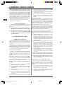
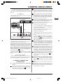
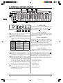
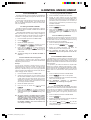
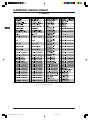
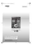
U-CONTROL UMX49/UMX61
DATA-MANFULL_UMX49_ENG_Rev_A.pmd 1
User’s Manual
Version 1.0 January 2006
12.01.2006, 20:36
U-CONTROL UMX49/UMX61
IMPORTANT SAFETY PRECAUTIONS
DETAILED SAFETY INSTRUCTIONS:
1) Read these instructions.
2) Keep these instructions.
3) Heed all warnings.
4) Follow all instructions.
CAUTION:
To reduce the risk of electric shock, do not remove
the cover (or back). No user-serviceable parts
inside; refer servicing to qualified personnel. Only
qualified personnel may perform repairs.
WARNING: The apparatus shall not be exposed to dripping or
splashing and that no objects filled with liquids, such
as vases, shall be placed on the apparatus.
This symbol, wherever it appears, alerts you to the
presence of uninsulated dangerous voltage inside
the enclosure—voltage that may be sufficient to
constitute a risk of shock.
This symbol, wherever it appears, alerts you to
important operating and maintenance instructions
in the accompanying literature. Please read the
manual.
5) Do not use this apparatus near water.
6) Clean only with dry cloth.
7) Do not block any ventilation openings. Install in accordance
with the manufacturer’s instructions.
8) Do not install near any heat sources such as radiators,
heat registers, stoves, or other apparatus (including
amplifiers) that produce heat.
9) Do not defeat the safety purpose of the polarized or
grounding-type plug. A polarized plug has two blades with
one wider than the other. A grounding type plug has two
blades and a third grounding prong. The wide blade or the
third prong are provided for your safety. If the provided plug
does not fit into your outlet, consult an electrician for
replacement of the obsolete outlet.
10) Protect the power cord from being walked on or pinched
particularly at plugs, convenience receptacles, and the point
where they exit from the apparatus.
11) Only use attachments/accessories specified by the
manufacturer.
12) Use only with the cart, stand, tripod, bracket, or table
specified by the manufacturer, or sold with the apparatus.
When a cart is used, use caution when moving the cart/
apparatus combination to avoid injury from
tip-over.
13) Unplug this apparatus during lightning storms or when
unused for long periods of time.
14) Refer all servicing to qualified service personnel.
Servicing is required when the apparatus has been damaged
in any way, such as power supply cord or plug is damaged,
liquid has been spilled or objects have fallen into the
apparatus, the apparatus has been exposed to rain or
moisture, does not operate normally, or has been dropped.
15) CAUTION - These service instructions are for use by
qualified service personnel only. To reduce the risk of electric
shock do not perform any servicing other than that contained
in the operation instructions unless you are qualified to do
so.
2
DATA-MANFULL_UMX49_ENG_Rev_A.pmd 2
SAFETY PRECAUTIONS
12.01.2006, 20:36
U-CONTROL UMX49/UMX61
U-CONTROL
The Ultimate Studio in a Box: 49-Key USB/MIDI Controller Keyboard with USB/Audio
Interface, 50 Software Instruments and Ableton® Live Lite 4 BEHRINGER Edition
UMX49
UMX61
V
Unleash your creativity and play 50 virtual instruments and synthesizers, take off with an unlimited number of sound creations.
Download more free instrument plug-ins and host software from www.behringer.com
V
Velocity-sensitive USB/MIDI keyboard featuring 49 full-size keys and unbeatable programming versatility, real-time control and
playability
V
USB/audio interface to connect your instruments and mixer, etc. to your computer for recording and playback
V
Powerful DAW software Ableton® Live Lite 4 BEHRINGER Edition included
V
Plug and play with Mac OS® X and Windows XP®
V
8 real-time rotary controls plus 10 assignable switches
V
Freely assign MIDI control changes to the modulation wheel, volume fader and pedal port for ultimate flexibility
V
Full 128 tone range via the octave shift function with multi-purpose LED status indication
V
Separate MIDI Out allows controlling external samplers, synths and other equipment
V
Runs via USB bus, batteries or a power adapter (not included)
V
High-quality components and exceptionally rugged construction ensure long life
V
Conceived and designed by BEHRINGER Germany
* All trademarks mentioned belong to their respective owners and are not affiliated with BEHRINGER®
3
YOUR U-CONTROL
DATA-MANFULL_UMX49_ENG_Rev_A.pmd 3
12.01.2006, 20:36
U-CONTROL UMX49/UMX61
TABLE OF CONTANTS
VORWORT
Dear Customer,
welcome to the team of
BEHRINGER users, and
thank you very much for
expressing your confidence in us by purchasing the U-CONTROL.
Writing this foreword
for you gives me great
pleasure, because it
represents the culmination of many months of
hard work delivered by
our engineering team to
achieve a very ambitious
goal: With the UMX we
present you our first
keyboard which, thanks
to its flexibility, can be
used on stage as a
master keyboard controller as well as a pure MIDI controller.
The task of designing our new U-CONTROL certainly meant a
great deal of responsibility, which we assumed by focusing on
you, the discerning user and musician. Meeting your expectations
also meant a lot of work and night shifts. But it was fun, too.
Developing a product usually brings a lot of people together, and
what a great feeling it is when all who participated in such a
project can be proud of what they’ve achieved.
It is our philosophy to share our enjoyment with you, because
you are the most important member of the BEHRINGER team.
With your highly competent suggestions for new products you’ve
made a significant contribution to shaping our company and
making it successful. In return, we guarantee you uncompromising
quality as well as excellent technical and audio properties at an
extremely reasonable price. All of this will enable you to give free
rein to your creativity without being hampered by budget
constraints.
We are often asked how we manage to produce such highquality devices at such unbelievably low prices. The answer is
quite simple: it’s you, our customers! Many satisfied customers
mean large sales volumes enabling us to get better purchasing
terms for components, etc. Isn’t it only fair to pass this benefit on
to you? Because we know that your success is our success too!
WICHTIGE SICHERHEITSHINWEISE .............................. 2
VORWORT ..................................................................... 4
1. EINFÜHRUNG .............................................................. 5
1.1 Bevor Sie beginnen ........................................................ 5
1.1.1 Auslieferung ........................................................ 5
1.1.2 Inbetriebnahme und Stromzufuhr ........................ 5
1.1.3 Garantie ............................................................... 5
1.2 Systemanforderungen .................................................... 6
2.2 USB-Modus und Standalone-Betrieb .............................. 7
2.2.1 Der USB-Modus ................................................... 7
2.2.2 Der Standalone-Betrieb ....................................... 7
3. BEDIENELEMENTE UND ANSCHLÜSSE .................... 7
4. BEDIENUNG ................................................................ 8
4.1 DER PLAY-MODUS .......................................................... 9
4.1.1 Das FACTORY MEMORY .................................... 9
4.1.2 Das USER MEMORY ............................................ 9
4.2 DER ASSIGN-MODUS ...................................................... 9
4.2.1 Einstellung des GLOBAL CHANNELs ................. 9
4.2.2 Die individuelle Kanal-Zuordnung ....................... 9
4.2.3 Zuordnung des GLOBAL CHANNELs: ............... 9
4.2.4 Die PANIK-Tastenkombination ............................. 9
4.2.5 Der SNAPSHOT SEND-Befehl ........................... 10
4.2.6 LOCAL OFF beim UMX ...................................... 10
4.2.7 Zuweisung von Bedienelementen .................... 10
4.2.8 Programm- und Bankwechsel .......................... 11
4.2.9 WeitereFunktionen der OCTAVESHIFT-Taster ..... 12
4.2.10 Die Anschlagsempfindlichkeit ........................... 12
4.2.11 Der FACTORY RESET-Befehl ............................ 13
5. TECHNISCHE DATEN ................................................ 13
6. ANHANG ................................................................... 14
7. GARANTIE ................................................................ 15
I would like to thank all of you who have made the B-CONTROL
possible. You have all made your own personal contributions,
from the developers to the many other employees at this company,
and to you, the BEHRINGER user.
My friends, it’s been worth the effort!
Thank you very much,
Uli Behringer
4
DATA-MANFULL_UMX49_ENG_Rev_A.pmd 4
FOREWORD / TABLE OF CONTENT
12.01.2006, 20:36
U-CONTROL UMX49/UMX61
1. INTRODUCTION
Thank you for showing your confidence in BEHRINGER
products by purchasing the UMX. The UMX is an extremely flexible
master keyboard with a controller unit that can be used for a
wide array of applications. Whether you need independent control
of computer rack synthesizers, general MIDI sound modules or
effects devices, or want to use the UMX for conveniently
operating sequencing software or computer plug-ins – the UMX
offers you tremendous ease of use and allows you to realize
your ideas intuitively.
USB Cable (included)
The following user’s manual is intended to
familiarize you with the unit’s control elements, so
that you can master all the functions. After having
thoroughly read the user’s manual, store it at a safe
place for future reference.
U-CONTROL UMX
Figure 1.1: Power supply via USB
1.1 Before you get started
1.1.1 Shipment
The U-CONTROL was carefully packed at the assembly plant
to assure secure transport. Should the condition of the cardboard
box suggest that damage may have taken place, please inspect
the unit immediately and look for physical indications of damage.
Damaged equipment should NEVER be sent directly
to us. Please inform the dealer from whom you
acquired the unit immediately as well as the
transportation company from which you took
delivery of the unit. Otherwise, all claims for
replacement/repair may be rendered invalid.
To assure optimal protection of your UMX during
transport, we recommend utilizing a carrying case.
Figure 1.2: The battery compartment on the bottom side of
the UMX
Please always use the original packaging to avoid
damage due to storage or shipping.
Open the battery compartment by pressing the shutter clamp
carefully in the direction of the battery compartment, while pulling
the cover of the compartment upwards.
Never let unsupervised children play with the
B-CONTROL or with its packaging.
Please note the following points when inserting the batteries:
V
The +symbol of the batteries must coincide with the
+symbol of the compartment! Incorrect polarity will damage
the electronics!
V
Do not mix old and new batteries! When you change the
batteries, always change all 3 batteries at the same time.
V
Do not use damaged batteries. The UMX could be damaged
due to the leakage of chemicals.
V
If you do not use the unit for an extended period of time,
please remove the batteries from the compartment. Here
again, the batteries could leak and damage the device.
Please dispose of all packaging materials in an
environmentally-friendly fashion.
1.1.2 Initial operation and power supply
Please make sure that the unit is provided with sufficient
ventilation, and never place the UMX on top of an amplifier or in
the vicinity of a heater to avoid the risk of overheating.
The power supply can be realized in different ways depending
on the main application area: For the installation of the UMX in a
studio environment, it is possible to connect the device directly
to a free USB port of the computer using the USB cable provided
(see fig. 1.1).
In case it is not possible to establish the power supply over
USB (e.g. because of an overload of the host computer due to
several USB devices connected), it is also possible to operate
the UMX with three 1.5-Volt batteries (type “AA”, see fig. 1.2).
After inserting the batteries, please close the battery
compartment and make sure the shutter clamp snaps into place
again.
If you do neither want to connect the power supply over USB
nor operate the unit with batteries, there is yet another possibility
to connect the UMX over an external power pack. Best suited
here is the BEHRINGER POWERSUPPLY PSU-SB. If you use a
different power supply, please observe the correct operational
data (9 V DC; 100 mA) and correct polarity of the connector
plug; you will find information about this above the DC input on
the rear of the unit. Reverse polarity can damage the electronics.
1.1.3 Online registration
Please, do remember to register your new BEHRINGER
equipment right after your purchase by visiting
www.behringer.com (alternatively www.behringer.de) and
kindly read the terms and conditions of our warranty carefully.
1. INTRODUCTION
DATA-MANFULL_UMX49_ENG_Rev_A.pmd 5
5
12.01.2006, 20:36
U-CONTROL UMX49/UMX61
Should your BEHRINGER product malfunction, our goal is to
have it repaired as quickly as possible. To arrange for warranty
service, please contact the retailer from whom the equipment
was purchased. Should your BEHRINGER dealer not be located
in your vicinity, you may directly contact one of our subsidiaries.
Corresponding contact information is included in the original
equipment packaging (Global Contact Information/European
Contact Information). Should your country not be listed, please
contact the distributor nearest you. A list of distributors can be
found in the support area of our website (www.behringer.com).
Registering your purchase and equipment with us helps us
process your repair claims quicker and more efficiently.
Thank you for your cooperation!
1.2 System requirements
For USB operation, a current WINDOWS® PC or MAC® with a
USB connection is sufficient. Both USB 1.1 and USB 2.0 are
supported.
The UMX supports the USB MIDI compatibility of
WINDOWS® XP and MAC OS X® operating systems.
The UMX can also be operated as a stand-alone MIDI
controller with no PC connected. Software control
via MIDI is also possible, provided your computer
has a MIDI interface.
V
Remotely controlling groove boxes, step sequencers, MIDI
generators and other “live” software
V
Program changes and volume control on sound generators
(just like on a master keyboard)
V
Can be used by band keyboardists, solo entertainers,
organists, electronic music performers, DJs, sound
engineers, home/project studio owners, theater technicians
etc. alike
And how does it work?
Remote control is realized by assigning the individual control
elements of the UMX to individual MIDI parameters. Whenever
one of these control elements is operated, the UMX generates
the control data assigned to this control element, which are then
transferred to external devices over a data link. Thus, for
example, the VOLUME/DATA fader is programmed ex works to
send data controlling the volume level of a channel.
The data connection is usually a standard MIDI cable with a
5-pole DIN plug on each end. Such cables should not exceed a
length of 15 meters. With the UMX there is one more data
connection available: the USB cable to the host computer. Here,
the cable should not exceed a length of 5 meters.
The data transmission takes place over 16 channels. The
control data generated by the individual control elements are
also called MIDI messages, which can be divided into 3 major
groups:
V
Channel Messages: Here, channel-specific control
information is transmitted. An example of a channel
message is the note-on instruction. As soon as a key is
played on the keyboard of the UMX, the device generates
an instruction which contains the pitch, channel number
and velocity. The receiving sound generator “knows” which
tone has to be played.
V
System Messages: These messages are not channelspecific but relate to the entire system to which they are
sent. They are divided into 3 groups: System Exclusive
Messages (for operating system backup, updates,
management of memory contents); System Real-Time
Messages (e.g. for remote control of other devices);
System Common Messages (e.g. for the synchronization
of several devices).
V
Control Messages: Also known as Control Changes or
Controllers, abbreviated as “CC… (controller number)”.
There are 128 controllers in total, which are numbered
from 0 to 127.
2. INTRODUCTION TO MIDI
2.1 MIDI control for beginners
Application possibilities for the UMX models are truly wideranging. We’ll start with a couple of general explanations and
examples that should quickly let you get a good understanding of
MIDI basics.
The definition of the MIDI standard began in 1982 with the
cooperation of various international companies (MIDI: Musical
Instruments Digital Interface). At that time, musicians were looking
for a possibility of managing the communication of electronic
musical instruments of different makes with one another.
What exactly does the UMX do?
Simply put, this a remote control for all kinds of MIDI equipment.
Using the faders, encoders and buttons, the foot pedal and the
keyboard, an entire array of control instructions can be
generated, which in turn can control the most diverse functions
of external devices.
What kinds of equipment can I control with the UMX?
You can basically control any device supporting the MIDI format.
Both hardware and software MIDI devices are controlled in exactly
the same way. The only difference is in the wiring.
Here are a couple of suggestions on how you can use
your UMX:
V
Editing sound parameters of (virtual) synthesizers, sound
samplers, GM/GS/XG sound generators
V
Controlling parameters on effects equipment/software plugins such as effects processors, reverbs, compressors,
equalizers etc.
V
Remotely controlling software mixers (volume, panorama,
mute functions, etc.)
V
Remotely controlling transport functions (playback, forward,
stop etc.) on sequencers, hard disk recorders, drum
computers etc.
V
Live control of volume and sound parameters on expanders
6
DATA-MANFULL_UMX49_ENG_Rev_A.pmd 6
Please refer to the table on page 16 to find out which
type of controller you are currently working with.
MIDI data are only control data and contain no audible
audio information! The data transmission takes
place over 16 channels.
What settings do I have to make? Where? How?
Basically, which control element generates which controller
must be set on the UMX, and how arriving controller commands
should be interpreted must be set on the receiving device.
Regarding controller assignment, there are two possible
principles:
V
You use the preset controller configuration set in the
factory (see fig. 2.1). In this case, you only need to make
the assignments on the receiving device.
V
You use your own controller configuration set up in
ASSIGN mode. How to assign controllers to the UMX is
described in chapter 4 “operation”.
2. INTRODUCTION TO MIDI
12.01.2006, 20:36
U-CONTROL UMX49/UMX61
2.2 USB mode and stand-alone operation
The UMX can be operated as a USB interface or stand-alone
device. The two modes are different with respect to the MIDI
signal flow.
2.2.1 USB mode
When the UMX is linked via USB to a computer, the signal flow
is as shown below (fig. 2.1).
VOLUME
MUTE
DEMO
FILTER
LEVEL
PROG
TYPE
COMBI
PLAY
The PITCH BEND wheel is normally used to change the
pitch in real time. In this way, a sound can be “bent”
upwards/downwards by several half-tones while playing.
As a default factory setting, pitch bending is assigned to
this wheel. However, in ASSIGN mode you can assign any
MIDI control command to the pitch wheel.
Ex works, the VOLUME/DATA fader controls the volume
of the notes played on the keyboard (MIDI CC 7). In ASSIGN
mode, it can be set to control any MIDI controller.
Sound-Modul
PHONES
The MODULATION wheel functions ex works as a
conventional modulation wheel (MIDI CC 1). In ASSIGN
mode, any MIDI controller can be assigned to it. When you
release the MODULATION wheel, it retains its adjusted
value.
POWER
The ASSIGN button allows you to assign different
functions to the various control elements.
The basic principle is always the same:
IN
1) Press the ASSIGN button and keep it pressed. The
status LED above the button lights up. The UMX signals
that it has entered ASSIGN mode.
OUT
(intern)
2) Select the control element to which you would like to
assign a new MIDI function by operating it.
MIDI
USB
3) Release the ASSIGN button.
ON
OFF
(intern)
Fig. 2.1: Block diagram of MIDI signal flow
After the UMX has been connected to the host computer, a
virtual MIDI IN and MIDI OUT interface is emulated.
MIDI data generated in the UMX are first sent over the USB
interface to the host computer, where they are received at the
emulated MIDI IN. A sequencer software running on the host
computer receives the MIDI data via the MIDI IN and relays them
to the emulated MIDI OUT – if all sequencer parameters are set
properly. The data are then sent back to the UMX via the USB
interfaces on the computer/UMX, where they are looped through
to the physical MIDI OUT (
). From here, the MIDI data are sent
to the devices connected to the MIDI OUT.
The MIDI OUT connector
can also be used as a normal MIDI
interface, independently of the sequencer software operating
the UMX.
2.2.2 Stand-alone operation
When the UMX25 is not linked via USB to a computer, it is
automatically set to stand-alone mode. In this case, the UMX25
can only send out MIDI data from its MIDI OUT connector.
3. CONTROL ELEMENTS AND
CONNECTIONS
The following factory settings refer to GLOBAL MIDI
channel 1.
The keyboard of the UMX25: 25 large, velocity-sensitive
keys for maximum playing comfort. The keyboard not only
provides for playing, but also functions
as an encoder
in the context of the assignment procedure.
4) Depending on the choice you made, you may have to
define an additional value range (see below for more
details).
5) Press the
-Taste. button on the keyboard to
confirm your assignments. To discard your assignments
either press the
-button or the ASSIGN button
again. In either case the ASSIGN LED goes out and the
UMX quits ASSIGN mode.
The USER MEMORY button is used to recall the internal
memory. The internal memory contains all assignment
information set in ASSIGN mode. Any changes that were
made after USER MEMORY selection are automatically
saved without further user prompts. The USER MEMORY
is retained even after the unit is switched off.
The two OCTAVE SHIFT buttons are preset to shift the
keyboard range by up to three octaves up or down. The
associated LEDs help you identify the current octave setting
(see table 3.1). Since the OCTAVE SHIFT buttons can also
be assigned to any MIDI controller, we would like to refer
you to chapters 4.2.8 and 4.2.9 for detailed information.
The eight high-resolution rotary controls R1 – R8 generate
continuous controller information. They are the controllers
that are shown above the buttons in the table
. All
rotary controllers can be assigned to any controller in
ASSIGN mode.
The eight buttons B1 - B8 generate switch controllers.
Again, they are assigned to various functions ex factory
(see table
on the device). Like the rotary controls the
buttons can be freely assigned to any controller in ASSIGN
mode.
The table shows the controller assignment preset at the
factory.
Keyboard legend: Informs you about the special functions
performed by individual keys on the keyboard. The
individual elements of the keyboard legend are described
in detail in chapter “4. Operation”.
3. CONTROL ELEMENTS AND CONNECTIONS
DATA-MANFULL_UMX49_ENG_Rev_A.pmd 7
12.01.2006, 20:36
7
U-CONTROL UMX49/UMX61
Fig. 3.1: TOP view of the UMX
4. OPERATION
We will explain the operation of the UMX in detail in the following.
You must observe the following: There is a differentiation
between push-buttons (refer to control elements
) and
keys (control element
)! Please do not confuse these!
4.1 THE PLAY MODE
Fig. 3.2: Rear panel connectors
Use this socket to supply the UMX with current from an
external power supply unit (not included).
The USB connector of the UMX. The connector (type B) on
the device is connected using the cable supplied to a free
slot on the host computer (where you will find a type A
connector). It is compatible with the USB1.1 and/or USB2.0
standards.
Operation
press once
press 2nd
time
press 3rd
time
press both
buttons
Octave shif t
Shif t one octave
up or dow n
Shif t 2 octaves
up or dow n
Shif t 3 octaves
up or dow n
Reset (all octave
shif ts are reversed)
LED
LED on
4.1.1 THE FACTORY MEMORY
The FACTORY MEMORY is the installed memory in which the
basic settings of the UMX are defined. The controller map
described under
is the most important item of the FACTORY
MEMORY. These settings are automatically loaded after each
start of the device and control many useful parameters.
Instructions which are changed within a session are discarded
when the device is switched off. We have equipped the UMX
with a USER MEMORY, in order to still be able to store changed
allocations.
f lashing
f lashing
4.1.2 THE USER MEMORY
LED of f
Settings which are stored in the USER MEMORY remain stored
in the internal Flash ROM and are retained after the device is
switched off.
Table 3.1: LED activity depending on the
OCTAVE SHIFT status
In addition to the connection to the computer, you can use
the MIDI OUT to connect additional MIDI devices, so that the
UMX transforms into a fully-featured, easily accessible
MIDI interface for your host computer.
Use the FOOT SWITCH connector to connect a sustain
pedal. This interface is factory preset and assigned to
the MIDI parameter “Foot Pedal” (CC 64), which represents
a switch controller. When the pedal is pressed (and held)
in normal Play mode, it generates a controller with the
value 127. When the pedal is released, the controller falls
back to 0 (typical piano sustain pedal behavior). Apart
from that the pedal assignment is the same as the button
assignment, i.e. you can assign any MIDI controller to it.
The UMX will be in the Play Mode immediately after it is switched
on. Here you can immediately begin to play, modify the filtering
process via the rotary controls, execute panning, control
software synthesizers and so on...
Change to the USER MEMORY by pressing push-button
. If
you call up the USER MEMORY for the first time, the settings of
the FACTORY MEMORY will be used initially. As soon as you
execute changes in the existing controller map, they are
automatically stored - without requiring any further action.
In the USER MEMORY, allocations including channel information
of the following control elements can be permanently stored:
- FOOT SWITCH connection
- OCTAVE SHIFT push-button
- VOLUME/DATA fader
- PITCH BEND wheel
The POWER switch is used to switch the unit on and off.
- MODULATION wheel
Please close all programs if you want to switch off
the UMX25 while the computer is running or
terminate the USB connection.
- Rotary controls R1 - R8
8
DATA-MANFULL_UMX49_ENG_Rev_A.pmd 8
- Push-buttons B1 - B8
4. OPERATION
12.01.2006, 20:36
U-CONTROL UMX49/UMX61
4.2.3 Assigning the GLOBAL CHANNELs:
4.2 THE ASSIGN MODE
As already mentioned in previous chapters, the ASSIGN Mode
is a powerful tool to optionally reconfigure the UMX into an ultracomfortable controller.
1)
Press the ASSIGN push-button and hold it down.
2)
Activate the control element for which the GLOBAL
CHANNEL is to be set. If this is a controller or fader, briefly
move the control element; when you have decided on a
push-button, press this push-button once. The UMX now
"knows" to which control element you would like to assign
a GLOBAL CHANNEL.
3)
Release the ASSIGN push-button.
4)
Press the
5)
Finally, press the
key. In order to discard your
key or press the
assignments, please press the
ASSIGN push-button again. The ASSIGN LED will go off
in all 3 cases.
The basic logic of the allocation process has been introduced
to you in chapter „3 Control elements“. In the following we will
offer you more detailed information to enable you to use the UMX
even more efficiently.
4.2.1 Setting the GLOBAL CHANNEL
The UMX recognizes two separate classifications in regard to
MIDI channels. There is a GLOBAL CHANNEL and 15 additional
SINGLE CHANNELs.
The GLOBAL MIDI CHANNEL is the channel through which all
MIDI commands are sent in the factory setting: messages by
various control elements, as well as the Note On and Note Off
commands. To change this channel, proceed as follows:
1)
Press the ASSIGN push-button and hold it down.
2)
Press the
3)
Release the ASSIGN push-button.
4)
Define the GLOBAL CHANNEL by operating one of the
keys
through
on the keyboard.
5)
Finally, press the
key. In order to discard your
assignments, please press the
key or press the
ASSIGN push-button again. The ASSIGN LED will go off
in all 3 cases.
key.
key.
4.2.4 The PANIC key combination
Imagine that you have been working continuously on one song
for several hours and a note suddenly "hangs up". If you now
execute a PANIC command, a sound producing device receiving
this command becomes silent immediately.
1)
Press the ASSIGN push-button and hold it down.
2)
Press one of the two
3)
Release the ASSIGN push-button. The device will
automatically return to the normal play mode.
The factory setting for the GLOBAL CHANNEL is
channel 1.
keys or
.
The command "All Notes Off" will be sent
immediately after you have pressed one of the two
keys.
4.2.5 The SNAPSHOT SEND command
4.2.2 The individual channel assignment
The assignment of individual control elements to defined
channels is useful if you want to control several external devices
independently from each other.
Example:
You are playing synthesizer A through channel 2 with the
keyboard and have a sequencer program controlling another
synthesizer B through channel 5. You can now control the filter
frequency of device B through one of the eight jog/shuttle
controls in real time and simultaneously continue to play device A
without changing the filter frequency.
1)
Press the ASSIGN push-button and hold it down.
2)
Activate the control element, for which another channel
than the GLOBAL CHANNEL is to be set. If this is a controller
or fader, briefly move the control element; when you have
decided on a push-button, press this push-button once.
The UMX now "knows" to which control element you would
like to assign a SINGLE CHANNEL.
3)
Release the ASSIGN push-button.
4)
Press one of the 16 channel keys
.
5)
Finally, press the
key. In order to discard your
assignments, please select the
key or press the
ASSIGN push-button again. The ASSIGN LED will go off in
all 3 cases.
through
All control elements of the UMX follow the GLOBAL
CHANNEL in their channel settings (factory settings).
This means that a control element is always in the
GLOBAL CHANNEL until you assign it to another
channel. Please also consider this when you change
the GLOBAL CHANNEL, since various elements will
also change accordingly!
The SNAPSHOT command triggers the transmission of all
parameters including their current values. All control element
assignments as well as their temporary settings on the respective
channels are transmitted to the MIDI OUT socket and to the USB
output of the UMX.
It is possible by this method to transfer the complete UMX
mapping to a sequencer software at the beginning of a song.
This is to make sure the song is played with the last valid controller
values. Apart from this, the SNAPSHOT allows you to reset the
correct values in an external device where parameters have
shifted.
1)
Press the ASSIGN push-button and hold it down.
2)
Press the
3)
Release the ASSIGN push-button. The device automatically
returns to the normal play mode.
push-button on the keyboard.
The SNAPSHOT command is transmitted
immediately after activating the keyboard.
4.2.6 LOCAL OFF in the UMX
The LOCAL OFF in the UMX has the effect that value entries
made via the control elements are neither transmitted to the MIDI
OUT socket nor to the USB OUT. It is therefore possible in the
LOCAL OFF mode, for example, to readjust the rotary controls
without transmitting data to the generally selected external
devices.
1)
Press the ASSIGN push-button and hold it down.
2)
Press the
3)
Release the ASSIGN push-button again and complete the
desired settings on the control elements.
4)
Then, press the
key or the
key. The LED
of the ASSIGN key goes off in both cases and you are in
normal play mode again.
key.
4. OPERATION
DATA-MANFULL_UMX49_ENG_Rev_A.pmd 9
9
12.01.2006, 20:36
U-CONTROL UMX49/UMX61
4.2.7 Assignment of control elements
We explained in chapter 4.2.2 how an individual channel can
be assigned to each control element. You will now find out how
to assign new controllers and a channel.
Please note two exceptions in conjunction with the pushbuttons and/or the sustain pedal.
a) The assignment for rotary controls R1 - R8, the
MODULATION controller, the PITCH BEND wheel, as well
as the DATA fader
1)
Press the ASSIGN push-button and hold it down.
2a) If you would like to assign one of the eight rotary controls,
turn the respective controller.
2b) If you assign the MODULATION controller, please activate
one of the keys located below the lettering
,
,
or
. You can bypass step 5, if you decide on the
and/or the
key. The MIDI controller
“MODULATION” (CC 1) and/or “CHANNEL VOLUME” (CC
7) is then directly assigned to the MODULATION controller
without having to enter a controller number first.
2c) If you assign the PITCH BEND wheel, please activate one
of
the
keys
located
below
the
lettering
,
or
. You can
bypass step 5, if you decide on the
key. The
original pitch bend function is then directly assigned to
the PITCH BEND wheel.
2d) If you complete an assignment for the DATA fader, please
activate one of the keys located below the lettering
,
or
. You can bypass
key. The original volume
step 5 if you decide on the
function is then directly assigned to the DATA fader.
3)
Release the ASSIGN push-button again.
4)
Press one of the 16 channel push-buttons
through
to define the channel.
5)
Press the number keys on the keyboard in sequence until
you have completely entered the desired controller number.
Only value entries between 0 and 127 are possible. Greater
values are ignored by the device.
Example:
- Press
for example.
- Press
select CC 107.
6)
and
,
if you have decided on CC 14,
and
if you would like to
Finally press the
key. In order to discard your
assignments, please press the
key or press the
ASSIGN push-button again. The LED of the ASSIGN pushbutton will go off in all 3 cases.
b) Assigning push-buttons B1 - B8 and the optional sustain
pedal connected to the socket
.
1)
Press the ASSIGN push-button and hold it down.
2)
Press the related control element once (however, it is not
necessary to continue pressing it).
3)
Release the ASSIGN push-button again.
4)
Press one of the 16 channel push-buttons
through
to define the channel.
5)
Press the number keys on the keyboard in sequence until
you have completely entered the desired controller number.
Only value entries between 0 and 127 are possible. Greater
values are ignored by the device.
6)
Finally, press the
key. In order to discard your
assignments, please press the
key or press the
ASSIGN push-button again. The LED of the ASSIGN pushbutton will go off in all 3 cases.
10
DATA-MANFULL_UMX49_ENG_Rev_A.pmd 10
If you assign CC 07 (Channel Volume) to the pushbuttons, a channel volume of 0 is triggered each
time you press the push-button. This means the
channel is always mute. This feature is very useful
for live operation.
If you use controller CC 10 (panning) for the pushbuttons or the sustain pedal, pressing the control
element transmits value 64. This results in hearing
the content of the channel in the center of the
stereo panorama.
Der Befehl “All Notes Off” wird sofort gesendet,
nach-dem Sie eine der beiden Tasten gedrückt
haben.
4.2.8 Program and bank change
You have three different optionsachieving a program change
in external devices with the UMX. This is a very powerful function,
which will enable you to use the full spectrum of all of your
sound producers.
Options a) and b) will allow you to select any programs by
means of a defined selection procedure, which always has to
be completed. The process is generally accelerated in the third
option c), so that you will be able to directly select programs by
pressing the push-button once.
a) If you are sure that you want to select from 128
different programs only, you will achieve the ASSIGN
mode program change by the following method. As soon
as the quantity of 128 is exceeded, however, you must
apply the process described under paragraph b).
1)
Press the ASSIGN push-button and hold it down.
2)
Press one of the 16 white channel keys
through
on the keyboard. You have now defined the
channel by which the program change will be transmitted.
3)
Release the ASSIGN push-button.
4)
Press the
5)
Press the number keys in sequence until you have
completely entered the desired program number. Only value
entries between 0 and 127 are possible. Greater values
are ignored by the device.
key.
Example:
- Press
and
program 15, for example.
- Press
,
to select program 127.
6)
if you have decided on
and
if you would like
Press the
key. In order to discard your assignments,
please press the
key or press the ASSIGN pushbutton again. The ASSIGN LED will go off in all 3 cases.
b) If you have more than 128 programs, you must apply
the following process to achieve a program change. In
this case, your programs will be organized in banks which
are activated by a special MIDI command: the BANK
SELECT command. In the following section, this
command is briefly described. A brief introduction for
this is listed in the following:
The BANK SELECT command consists of two parts: An MSB
part and an LSB part.
The MSB part describes a value range of 128 different values
and is the more important part of the DATA BASE SELECT
command for many external devices.
4. OPERATION
12.01.2006, 20:37
U-CONTROL UMX49/UMX61
The LSB part describes each of the 128 MSBs in another 128
individual stages. Both are individually numbered from 0 to 127.
2)
Select the OCTAVE SHIFT push-button which you want to
assign to the program change function.
The enormous value range of a total of 128 x 128 = 16.384
different values is therefore available to you via the BANK
SELECT command. This theoretically means that you could use
external devices which support the same amount of different
banks.
3)
Release the ASSIGN push-button again.
4)
Defined the channel by which the program change will be
transmitted. Press one of the 16 channel keys
through
on the keyboard.
If you consider that each of these banks again contains another
128 individual programs, you will receive the unbelievably large
number of 2,097,152 different options to organize these
programs.
5)
Press the
key. Then press the number keys on
the keyboard in sequence until you have completely entered
the desired preset number. Only value entries between 0
and 127 are possible. Greater values are ignored by the
device.
6)
Finally, press the
key. In order to discard your
assignments, please select the
key or press the
ASSIGN push-button again. The ASSIGN LED will go off in
all 3 cases.
1)
Press the ASSIGN push-button and hold it down.
2)
Press one of the 16 channel keys
, or press the
key.
3)
Release the ASSIGN push-button.
4)
Press the
key. Then press the number keys in
sequence until you have completely entered the desired
BANK MSB number. Only value entries between 0 and
127 are possible. Greater values are ignored by the device.
through
The BANK MSB has now been defined.
Example:
- Press
and
14, for example.
- Press
,
select MSB 107.
5)
if you have decided on MSB
and
if you would like to
Now define the BANK LSB by pressing the
key.
Then enter the number value of the BANK LSB with the
already familiar procedure (see step 4). The same entry
rules apply as for the BANK MSB.
You have defined the bank in which the desired program
will be called up in steps 4 and 5. Now all you have to
define is the program itself:
6)
key and then press the number keys
Press the
in sequence until you have completely entered the desired
program number. Only entries between 0 and 127 are
possible, greater values are ignored by the device. Ready!
7)
Finally, press the
key. In order to discard your
assignments, please press the
key or press the
ASSIGN push-button again. The ASSIGN LED will go off
in all 3 cases.
Example:
You want to select preset No. 49 in bank 25 of an external
device on channel 14 via the UMX. Only the LSB will be used to
describe the bank, since the bank number remains less than
128. The MSB in this case equals 0.
1)
Press and hold the ASSIGN push-button.
2)
Press the channel key
3)
Press and hold the ASSIGN push-button.
2)
Press the channel key.
4)
Then, press the
5)
Press
buttons
6)
Define the program: Press the
key and then the
and
keys for program 49.
7)
Press the
.
key or the
key.
key and then describe bank 25 with pushand
.
key.
c) Direct program selection through the two OCTAVE
SHIFT push-buttons.
1)
Press the ASSIGN push-button and hold it down.
As soon as you have assigned the direct program
selection to one or both OCTAVE SHIFT pushbuttons simultaneously, pressing both pushbuttons will not activate ANYTHING!
4.2.9 Additional functions of the OCTAVE SHIFT pushbuttons
The OCTAVE SHIFT push-buttons of the device are in their initial
state every time the UMX is switched on (refer to table 3.1).
Further special functions can be assigned to both push-buttons
in the ASSIGN mode in addition to the already covered functions
regarding direct program change and octave transposition:
a)
Transposition in individual semitone steps
b)
Sequential scrolling in program libraries
c)
Optional controller functions
As soon as you assign a function to one of the two
push-buttons, the second push-button will
automatically assume the same function - however,
it is still restricted in its functionality: It is not capable
of sending data until you assign a function to this
push-button with the ASSIGN procedure.
As soon as you assign an individual MIDI channel to
one of the two push-buttons, the other push-button
will also switch to this channel. This also applies if
you return to the GLOBAL CHANNEL.
a) Transposition in individual semitone steps
1)
Press the ASSIGN push-button and hold it down.
2)
Press the
3)
Release the ASSIGN push-button.
4)
key. In order to discard your
Finally, press the
assignments, please press the
key or press the
ASSIGN push-button again. The ASSIGN LED will go off
in all 3 cases.
key.
Pressing the right hand one of the two push-buttons causes a
shift by one semitone upward pressing the left hand one leads to
a shift by one semitone downward. Pressing both push-buttons
cancels all transpositions.
A keyboard can consist of a maximum of 128
semitones according to the MIDI standard. If you have
reached the lower or upper end of this tone range
with the transposition function, you cannot exceed
the highest or lowest tone despite continued
pressing of the transposition push-button. This also
applies to the transposition in octave steps.
4. OPERATION
DATA-MANFULL_UMX49_ENG_Rev_A.pmd 11
11
12.01.2006, 20:37
U-CONTROL UMX49/UMX61
b) Sequential scrolling in program libraries.
4.2.10 RANGE definitions
Most sound producers have the option to store presets in a
separate bank (frequently called a User Bank). If the sequence
of songs to be played at a concert is defined by your band, you
can store all of the sounds used for the gig in the User Bank in
the sequence they occur in the concert and completely
concentrate on your playing. A cumbersome search for sounds
in the sound producers is no longer required thanks to the
OCTAVE SHIFT push-buttons.
1)
Press the ASSIGN push-button and hold it down.
2)
Press the
key.
3)
Release the ASSIGN push-button.
4)
Finally, press the
key. In order to discard your
assignments, please press the
key or press the
ASSIGN push-button again. The ASSIGN LED will go off
in all 3 cases.
The RANGE parameter can be defined for the PITCH BEND
wheel and the key velocity.
a) for the PITCH BEND RANGE: This defines to what extent
the movement of the PITCH BEND wheel affects the pitch of the
sound. Proceed as follows to change the PITCH BEND RANGE:
1)
Press the ASSIGN button and keep it pressed.
2)
Use the number keys to enter the keyboard velocity (see
table 4.1).
3)
Release the ASSIGN button.
4)
Confirm your selection with
assignments either press the
button again.
KEY
SOFT: key pressure is very sensitive; low
velocity changes create high changes in
volume level
Please note that you must assign an individual MIDI channel to
the OCTAVE SHIFT push-buttons if you do not want to work in
the GLOBAL CHANNEL (refer to chapter 4.2.2).
MEDIUM: key pressure is “normal”; (very) hard
hit notes are (very) loud, (very) soft hit notes
produce (very) low volume
c) Optional controller functions
Please note that the OCTAVE SHIFT push-buttons generate
switch controllers in the event of a controller assignment. One
of the two values 0 or 127 will always be produced.
There are two exceptions: if you assign controller
CC 07 (Channel Volume) to the OCTAVE SHIFT pushbuttons, pressing one of the push-buttons will
always generate the value 0. In case of controller
CC 10 (panning), pressing a push-button will always
produce the value 64.
EFFECT ON KEY VEOLCITY
OFF: velocity value is fixed to 110.
Change of key pressure has no effect on
volume level.
Pressing the right hand one of the two push-buttons now causes
your external device to switch one preset number upward to be
switched upward in your external device; pressing the left hand
causes a step downward in your preset library. By pressing both
push-buttons you jump to Preset 0 in the current bank.
. To discard your
button or the ASSIGN
HARD: key pressure is more unsusceptible
compared to all other settings
bis
invalid input
Table 4.1: Effect of RANGE definition on keyboard velocity
4.2.11 The FACTORY RESET command
To reset all settings on your UMX25, proceed as follows:
Please note that pressing both push-buttons
simultaneously does not generate anything when
assigning a controller.
1)
Press the ASSIGN button and keep it pressed.
2)
Press the one of the two OCTAVE SHIFT buttons to which
you want to assign a controller.
3)
Release the ASSIGN button.
4)
Press the number keys on the keyboard to enter the controller
number of your choice (as described in chapter 4.2.1).
5)
. To discard your
Confirm your selection with
assignments either press the
button or the ASSIGN
button again. In either case the ASSIGN LED goes out.
Remember to assign the OCTAVE SHIFT buttons to an individual
MIDI channel if you do not want to use the GLOBAL CHANNEL
(see chapter 4.2.2).
12
DATA-MANFULL_UMX49_ENG_Rev_A.pmd 12
1)
Press the ASSIGN push-button and hold it down.
2a) To cause a temporary FACTORY RESET, simultaneously
press both OCTAVE SHIFT push-buttons. All temporarily
changed control elements are returned to their factory
settings. The USER MEMORY, however, is retained and
will not be reset.
2b) Simultaneously press the
,
and
keys to perform a complete FACTORY RESET.
In this case, the USER memory is also overwritten, in addition
to resetting all control elements of the FACTORY MEMORY.
3)
Release the ASSIGN push-button again. The LED of the
ASSIGN push-button continues to be illuminated.
4)
Finally, press the
key. If you do not wish to perform
the RESET command, please press either the
key or press the ASSIGN push-button again.
4. OPERATION
12.01.2006, 20:37
U-CONTROL UMX49/UMX61
5. SPECIFICATIONS
USB connections
Type
Type B; USB1.1
MIDI connections
Type
5-pin DIN plug OUT
CONTROL ELEMENTS
Controller
1 control wheel with center reset
1 control wheel without center reset
8 rotary knobs
1 fader
Buttons
12 buttons
Keyboard
UMX49
49keys; velocity-sensitive
UMX61
61keys; velocity-sensitive
SWITCH PLUG
Foot pedal
1/4'' -Monojack with automatic
polarity recognition
POWER SUPPLY
USB
Battery
Mains connection
negative
3 x 1,5 Volt Mignon (Typ “AA”)
2 mm (1/13'’) DC connection, Center
9V
via:
China/Korea
Europe
Japan
Australia
UK
USA
, 200 mA DC, regulated; extern
PSU-SB-CN BEHRINGER 220 V~, 50 Hz
PSU-SB-EU BEHRINGER 230 V~, 50 Hz
PSU-SB-JP BEHRINGER 100 V~, 50/60 Hz
PSU-SB-SAA BEHRINGER 240 V~, 50 Hz
PSU-SB-UK BEHRINGER 240 V~, 50 Hz
PSU-SB-UL BEHRINGER 120 V~, 60 Hz
Power consumption
UMX49
max. 0.9 W
UMX61
max. 0.9 W
DIMENSIONS/WEIGHT
Dimensions (W x H x L)
UMX49
215 mm x 97 mm x 825 mm
UMX61
215 mm x 97 mm x 990 mm
Weight
UMX49
UMX61
3,904 kg
4,689 kg
BEHRINGER is constantly striving to manintain the highest professional standards. As a result of these efforts, modifications may be made from
time to time to existing products without prior notice. Specifications and appearance may differ from those listed or illustrated.
5. SPECIFICATIONS
DATA-MANFULL_UMX49_ENG_Rev_A.pmd 13
13
12.01.2006, 20:37
U-CONTROL UMX49/UMX61
6. APPENDIX
Tab. 6.1: MIDI-Controller overview
14
DATA-MANFULL_UMX49_ENG_Rev_A.pmd 14
6. APPENDIX
12.01.2006, 20:37
U-CONTROL UMX49/UMX61
7. WARRANTY
§ 1 OTHER WARRANTY RIGHTS AND NATIONAL LAW
1. This warranty does not exclude or limit the buyer’s statutory
rights provided by national law, in particular, any such rights
against the seller that arise from a legally effective purchase
contract.
2. The warranty regulations mentioned herein are applicable
unless they constitute an infringement of national warranty law.
2. If the product needs to be modified or adapted in order to
comply with applicable technical or safety standards on a national
or local level, in any country which is not the country for which
the product was originally developed and manufactured, this
modification/adaptation shall not be considered a defect in
materials or workmanship. The warranty does not cover any
such modification/adaptation, irrespective of whether it was
carried out properly or not. Under the terms of this warranty,
BEHRINGER shall not be held responsible for any cost resulting
from such a modification/adaptation.
Please do remember to register your new BEHRINGER
equipment right after your purchase by visiting
www.behringer.com (alternatively www.behringer.de) and
kindly read the terms and conditions of our warranty carefully.
3. Free inspections and maintenance/repair work are expressly
excluded from this warranty, in particular, if caused by improper
handling of the product by the user. This also applies to defects
caused by normal wear and tear, in particular, of faders,
crossfaders, potentiometers, keys/buttons, tubes, guitar strings,
illuminants and similar parts.
Registering your purchase and equipment with us helps us
process your repair claims quicker and more efficiently.
4. Damages/defects caused by the following conditions are
not covered by this warranty:
§ 2 ONLINE REGISTRATION
Thank you for your cooperation!
V
improper handling, neglect or failure to operate the unit in
compliance with the instructions given in BEHRINGER user
or service manuals.
V
connection or operation of the unit in any way that does
not comply with the technical or safety regulations
applicable in the country where the product is used.
V
damages/defects caused by force majeure or any other
condition that is beyond the control of BEHRINGER.
§ 3 WARRANTY
1. BEHRINGER (BEHRINGER International GmbH including all
BEHRINGER subsidiaries listed on the enclosed page, except
BEHRINGER Japan) warrants the mechanical and electronic
components of this product to be free of defects in material and
workmanship for a period of one (1) year* from the original date
of purchase, in accordance with the warranty regulations
described below. If the product shows any defects within the
specified warranty period that are not excluded from this
warranty as described under § 5, BEHRINGER shall, at its
discretion, either replace or repair the product using suitable
new or reconditioned parts. In the case that other parts are used
which constitute an improvement, BEHRINGER may, at its
discretion, charge the customer for the additional cost of these
parts.
2. If the warranty claim proves to be justified, the product will
be returned to the user freight prepaid.
3. Warranty claims other than those indicated above are
expressly excluded.
5. Any repair or opening of the unit carried out by unauthorized
personnel (user included) will void the warranty.
6. If an inspection of the product by BEHRINGER shows that
the defect in question is not covered by the warranty, the
inspection costs are payable by the customer.
7. Products which do not meet the terms of this warranty will
be repaired exclusively at the buyer’s expense. BEHRINGER will
inform the buyer of any such circumstance. If the buyer fails to
submit a written repair order within 6 weeks after notification,
BEHRINGER will return the unit C.O.D. with a separate invoice
for freight and packing. Such costs will also be invoiced
separately when the buyer has sent in a written repair order.
§ 4 RETURN AUTHORIZATION NUMBER
§ 6 WARRANTY TRANSFERABILITY
1. To obtain warranty service, the buyer (or his authorized
dealer) must call BEHRINGER (see enclosed list) during normal
business hours BEFORE returning the product. All inquiries must
be accompanied by a description of the problem. BEHRINGER
will then issue a return authorization number.
2. Subsequently, the product must be returned in its original
shipping carton, together with the return authorization number to
the address indicated by BEHRINGER.
3. Shipments without freight prepaid will not be accepted.
§ 5 WARRANTY REGULATIONS
1. Warranty services will be furnished only if the product is
accompanied by a copy of the original retail dealer’s invoice.
Any product deemed eligible for repair or replacement under the
terms of this warranty will be repaired or replaced.
This warranty is extended exclusively to the original buyer
(customer of retail dealer) and is not transferable to anyone
who may subsequently purchase this product. No other person
(retail dealer, etc.) shall be entitled to give any warranty promise
on behalf of BEHRINGER.
§ 7 CLAIM FOR DAMAGES
Failure of BEHRINGER to provide proper warranty service shall
not entitle the buyer to claim (consequential) damages. In no
event shall the liability of BEHRINGER exceed the invoiced value
of the product.
* Customers in the European Union please contact BEHRINGER
Germany Support for further details.
Technical specifications and appearance subject to change without notice. The information contained herein is correct at the time of
printing. The names of companies, institutions or publications pictured or mentioned and their respective logos are registered trademarks
of their respective owners. Their use neither constitutes a claim of the trademarks by BEHRINGER® nor affiliation of the trademark
owners with BEHRINGER®. BEHRINGER® accepts no liability for any loss which may be suffered by any person who relies either wholly
or in part upon any description, photograph or statement contained herein. Colours and specification may vary slightly from product.
Products are sold through our authorised dealers only. Distributors and dealers are not agents of BEHRINGER® and have absolutely no
authority to bind BEHRINGER® by any express or implied undertaking or representation. No part of this manual may be reproduced or
transmitted in any form or by any means, electronic or mechanical, including photocopying and recording of any kind, for any purpose,
without the express written permission of BEHRINGER Spezielle Studiotechnik GmbH. BEHRINGER® is a registered trademark.
ALL RIGHTS RESERVED. © 2005 BEHRINGER Spezielle Studiotechnik GmbH,
Hanns-Martin-Schleyer-Str. 36-38, 47877 Willich-Münchheide II, Germany.
Tel. +49 2154 9206 0, Fax +49 2154 9206 4903
7. WARRANTY
DATA-MANFULL_UMX49_ENG_Rev_A.pmd 15
15
12.01.2006, 20:37