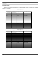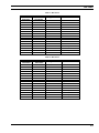
1
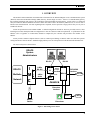
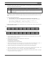
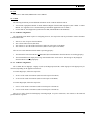
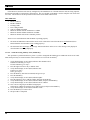
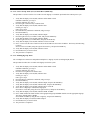
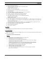
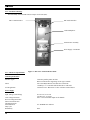
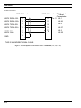
LBI-39000
Mobile Communications
EDACSTM Jessica
PBX Gateway
Systems Manual
LBI-39000
TABLE OF CONTENTS
1. OVERVIEW ................................................................................................................................................
3
1.1. Major Components ...............................................................................................................................
4
1.2. Operation ..............................................................................................................................................
5
1.3. Features.................................................................................................................................................
6
2. SYSTEM REQUIREMENTS......................................................................................................................
8
2.1. EDACS Software Requirements ...........................................................................................................
8
2.2. EDACS Hardware Requirements..........................................................................................................
10
2.3. EDACS System Compatibility..............................................................................................................
13
3. INSTALLATION ........................................................................................................................................
14
3.1. Installation At IMC ...............................................................................................................................
14
3.2. Installation At Sites...............................................................................................................................
25
4. COMPONENTS ..........................................................................................................................................
28
4.1. PBX Interface (PI) ................................................................................................................................
28
4.2. Audio Multiplexer.................................................................................................................................
31
4.3. Power Distribution Unit And -48V Power Supply................................................................................
32
4.4. PI/MUX Cabinet ...................................................................................................................................
33
4.5. MD110 LIM..........................................................................................................................................
33
5. GLOSSARY ................................................................................................................................................
34
APPENDIX A CABLE CONNECTIONS....................................................................................................... A-1
APPENDIX B APPLICABLE NEC ND4E INSTRUCTIONS ....................................................................... B-1
APPENDIX C UNPOPULATED VME CHASSIS ......................................................................................... C-1
APPENDIX D DRAWINGS ........................................................................................................................... D-1
This manual is published by Ericsson GE Mobile Communications Inc., without any warranty. Improvements and changes
to this manual necessitated by typographical errors, inaccuracies of current information, or improvements to programs and/or
equipment, may be made by Ericsson GE Mobile Communications Inc., at any time and without notice. Such changes will
be incorporated into new editions of this manual. No part of this manual may be reproduced or transmitted in any form or by
any means, electronic or mechanical, including photocopying and recording, for any purpose, without the express written
permission of Ericsson GE Mobile Communications Inc.
Copyright© June 1994, Ericsson GE Mobile Communications Inc.
2
LBI-39000
1. OVERVIEW
This manual contains installation and maintenance information for the Enhanced Digital Access Communications System
(EDACS) Jessica Private Branch Exchange (PBX) Gateway, known simply as Jessica. Jessica is a communications gateway
that connects an EDACS radio system to the local public switched telephone network (PSTN). Jessica works as a centralized
subsystem within an EDACS Multisite Network to allow interconnect calls to the PSTN by EDACS users, as well as calls to
EDACS users from the PSTN. For calls originating from a telephone, Jessica represents a single point of entry to every site in
an EDACS network.
Jessica incorporates the Ericsson MD110 PBX. A default configuration tailored for Jessica is provided; however, those
installing Jessica must modify the MD110 configuration to meet the customer’s MD110 requirements. A questionnaire on the
MD110 (refer to Appendix A of LBI-39039) should be completed by the customer and provided to the installer of the
MD110.
Jessica provides common telephone features (such as common speed dialing) to EDACS radio users and those persons
calling into EDACS from the PSTN. Standard ringing and busy tones are incorporated on both inbound and outbound calls.
The Jessica subsystem is shown below.
EDACS
System
Administrators
MD Terminal
PI Field Console
RS-232
RS-232
EDACS
Multisite
Network
I
M
C
6-Wire
RS-422
EDACS
Interface
PI
P
I
M
PSTN/PBX
Interface
T1/E1 ISDN
4-Wire
Audio
T1/E1 Audio
MD110
PSTN
MUX
Jessica
Extension
Interface
EDACS
Radio
EDACS
Radios
Modem
PSTN
Extensions
Figure 1 - Block Diagram of Jessica
3
LBI-39000
This manual includes instructions for installing Jessica around the world, so it will contain references to both T1 and E1
signaling (digital telephone signaling protocol) installation procedures. In some places the notation 23/30 is used; the 23
indicates the number of T1 voice channels and the 30 indicates the number of E1 voice channels. The configuration and
installation of the MD110 are covered in the Ericsson documentation listed below (documents with the BC number). A
section on configuring the MD110 is provided in LBI-39039, and a sample configuration disk is also supplied. Jessica is not
a local interconnect system associated with EDACS single-site systems. For information on local interconnect, refer to the
subject LBI presented in the list that follows.
The manuals listed below are referenced throughout this document. Some provide additional background information
and others may be useful for solving technical difficulties.
l
l
l
l
l
l
l
l
l
l
l
l
l
l
LBI-38894, GETC Maintenance Manual
LBI-38513, Local Interconnect
LBI-38938, CEC/IMC Overview
LBI-38939, IMC Maintenance Manual
LBI-38985, EDACS Site Controller Maintenance Manual
LBI-39001, EDACS Jessica PBX Gateway Operator's Manual
LBI-39039, EDACS Jessica PBX Gateway MD110 Configuration Manual
LBI-39040, EDACS Jessica PBX Gateway PBX Interface User's Manual
LBI-39080, EDACS Jessica PBX Gateway Operator’s Manual (Quick Reference Guide)
LZTU 106 1250, MD110 Technical Product Description, BC6
LZBU 106 100, MD110 Customer Library -- Small Basic, BC 6
EN/LZB 103 866, Installation MD110/50
62.6929.000.00, Equipment System PCM 30 FXM (ANT BOSCH MUX Manual)
NECA 365-454-000, Equipment Manual for ND4 Enhanced Digital Channel Bank Equipment
1.1. MAJOR COMPONENTS
Jessica contains three major components: a PBX interface (PI), an MD110 PBX, and a multiplexer (MUX).
PI
The PI provides the interface between the IMC and the MD110. It is responsible for telephone interconnect call
management. The PI has a VME bus architecture that includes three primary boards and the miscellaneous equipment below.
4
•
PI Controller (PIC) Board -- a single-board computer that utilizes a CISC 32-bit microprocessor. The PIC is
responsible for processing all interconnect calls. It also controls the interfaces to the floppy and hard drives through
a small computer systems interface (SCSI) port.
•
PI MSC Interface (PMI) Board -- a wide-area network (WAN) server board that provides a high-level data link
control (HDLC) link to the PIM controller board within the IMC.
•
Primary Rate Interface (PRI) Board -- provides the E1/T1 ISDN interface to the MD110 as well as the E1/T1 audio
interface to the IMC. If a T1 link is specified, a PRI-48 is used. If an E1 link is specified, a PRI-64 is used.
•
Hard Drive -- drive used for storing the application code, configuration parameters, and call activity.
•
Floppy Drive -- a 1.44 Mbyte, 3-1/2" drive for configuration parameter updates and application code upgrades.
•
VT100 field terminal -- used to manipulate files on the PI via a pSOS (UNIX-like shell) terminal interface running
on the PIC.
LBI-39000
MD110
The MD110 is an Ericsson Private Branch Exchange (PBX). Its primary building block is the line interface module
(LIM). The LIM performs all call processing functions. One LIM interfaces to the PI and either the Public Switched
Telephone Network (PSTN) or another PBX. It contains two to four circuit board cards which connect to a common
backplane. The backplane includes a processor bus and a device bus. The processor bus carries control data between the
device processors on the individual boards. The device bus carries voice or data to and from device boards.
In addition to the LIM, the standard MD110 has an alarm unit, an Ericsson dial-back modem for remote configuration, a
two-hour battery back-up, and up to eight on-premises extensions that allow a telephone to be directly connected to the
MD110 for testing purposes. A 386 PC for configuring the MD110 is optional.
The MD110 will also have one or more termination lines to the PSTN or another PBX. All types of digital and analog
trunks and tie lines are available based on customer needs. In addition, the MD110 will always have one digital ISDN T1 or
E1 trunk for connecting to the PI.
Multiplexer (MUX)
The Multiplexer (MUX), also called a Channel Bank, is used to combine 4-wire balanced audio inputs from the IMC,
bound for the Public Switched Telephone Network (PSTN), into a single digitized stream, and vice versa. In North America
and Japan the standard is a T1 multiplexer, and in Europe, Asia, and South America the standard is an E1 multiplexer.
A single T1 allows up to 23 voice circuits to be multiplexed together. A single E1 allows up to 30 voice circuits to be
multiplexed together. Each voice circuit has its own channel unit within the MUX.
PBX Interface Module (PIM)
Within the IMC, a PBX Interface Module (PIM) provides an audio path and a control signaling interface for Jessica. The
PBX Interface Module contains a controller card and up to eight audio cards.
1.2. OPERATION
Telephone interconnect messages can be initiated from an EDACS radio or from a telephone. This section describes the
processes that occur when a telephone call is implemented.
Radio-Originated (Outbound) Calls
When a radio user initiates a telephone interconnect call, the radio sends an interconnect request message to the control
channel. This message incorporates the digits to be dialed. The system forwards the call request message via the downlink to
the IMC. The IMC routes the request to Jessica via the PBX Interface Module in the IMC. Meanwhile, the originating radio
is directed to a working channel in preparation for the call connection.
The Jessica PBX Interface receives the call request message and translates it into a telephone call setup. The PI then
initiates the call setup using the PRI ISDN interface card. The PRI message is sent to the MD110. The MD110 routes the
call to the PSTN or customer-owned PBX. The PSTN then routes the call to the destination telephone. The PSTN indicates
to the MD110, which in turn notifies the PI, that the telephone terminal is ringing. The PI notifies the IMC, which in turn
generates ringing tones that are sent to the initiating radio.
When the telephone is answered, the PSTN indicates to the MD110, which then indicates to the PI, that the party being
called has answered. The connection is now established between the originating radio and the telephone terminal, and the
conversation proceeds.
Either the telephone user or the radio user can terminate the call. If the telephone user hangs up first, the PSTN notifies
the MD110, which indicates to the Jessica PI that the telephone party has disconnected. The PI sends a drop message to the
IMC, and the message is passed to the site where the radio has been assigned a channel.
5
LBI-39000
Alternately, the radio user can terminate a call by pressing the SPC or Clear key. In this case, EDACS sends the call drop
message to the IMC, which passes the drop message to the Jessica PI. On receiving the drop message, the PI disconnects the
telephone call connection to the MD110.
Telephone-Originated (Inbound) Calls
When the PSTN user dials the telephone number for the Jessica MD110, the PSTN routes the call to the MD110. Once
the connection is established, the PSTN user hears a dial tone generated by the MD110. This dial tone is the prompt for the
user to enter the access code and identify the desired destination radio or group.
The dialed digits are received by the MD110, which then processes the digits and routes the call to the PI. The PI
analyzes the digits passed from the MD110 and signals the IMC to set up an interconnect call to the indicated individual radio
or group.
The IMC identifies the site or sites that the individual or group members are logged on to and initiates a channel
assignment at those sites. The control channel directs the radio(s) to the assigned working channel. The channel confirmation
is passed back to the PI via the IMC. The PI then sends an alerting ringing indication back to the PSTN caller.
The radio user is alerted to the active interconnect call by a ringing tone generated by the IMC. The radio user accepts
the call by depressing the PTT button. This message is passed back to the PI, which then indicates to the MD110 and hence
the PSTN caller, that the radio has answered. The audio connection is then established and the call proceeds.
The call termination is identical to the process described for radio-originated calls.
1.3. FEATURES
The features of Jessica can be grouped into three classes: system features, telephone user features, and radio user
features. A list of the features in each class of calls is given below.
System Features
•
Basic centralized telephone interconnect, with inbound and outbound calls supported.
•
Up to 30 simultaneous calls for European, Asian, and South American systems with a digital E1 link. Up to 23
simultaneous calls for North American and Japanese systems with a digital T1 link.
•
Encrypted voice calls.
•
Full duplex telephone calls.
•
ISDN interface to the PSTN.
•
Automatic line clearing.
•
Authorization code disable for inbound calls (optional).
•
Activity Reports showing operational statistics collected by the PI. These reports can be spooled to disk or redirected to
port 2 of the PI.
6
LBI-39000
Telephone User Features
•
Basic telephone tones (ringing and busy).
•
Common speed dialing (standard MD110 feature).
•
Direct inward dialing (DID).
Radio User Features
•
Basic telephone tones (ringing and busy).
•
Common speed dialing.
•
Least-cost routing (LCR).
Jessica supports:
l
l
l
l
Full 16382 EDACS Users
Full 2048 EDACS Groups
Failsoft and Site Controller modes
Up to 30 simultaneous conversations (23 maximum in North America and Japan)
Jessica is purchased as: 4,8,12,...,23-channel T1
4, ... ,28,30-channel E1
7
LBI-39000
2. SYSTEM REQUIREMENTS
2.1. EDACS SOFTWARE REQUIREMENTS
Release 1.0 of Jessica requires the EDACS software revision levels shown below.
Table 1 - EDACS Component Software Version Requirements
Platform
PBX Interface (PI)
1.
2.
Minimum Software Version
PIC Operating System 349A9983G1
PI Application 349A9982G1
MD110
(purchased from Ericsson)
1.
2.
MD110 Software BC 6.2.1G
Configuration File 349A9986G1
CEC/IMC
1.
IMC Controller Board
U3 344A3565G10
U58 344A3567G10
U59 344A3568G10
U3 344A3565G7, C3 XLTR only
U58 344A3569G4, C3 XLTR only
U59 344A3570G4,C3 XLTR only
IMC Audio Board
U99 344A3564G10
Conventional Interface Audio Board
19D903324P1
U13 344A3694G10
CEC/IMC Manager
Disk 344A3630G10
2.
3.
4.
C3 Maestro
1.
2.
Disk 344A3922G10
CLB U4 344A4245G10
System Manager
VAX
PDP
344A4583G3
19A149495G11
Site Controller
344A3265G4
8
LBI-39000
Table 1- EDACS Component Software Version Requirements (Cont.)
Platform
GETC-1E CC/WC Main Board
Link1 GETC UL/DL Main Board
GETC Turbo Board
Minimum Software Version
U2 349A9607G2
U2 344A4895G1
Disk 344A4414G3
GETC Turbo Loader (PC)
Disk 344A4414G3
SCAT GETC and SCAT/DL
U2 344A3835G1
DVIU VGE
1.
2.
344A4516G4
Voice Guard
344A3000P91
Aegis
344A3000P290
Unencrypted Aegis
344A3000P490
DVIU DES
1.
2.
344A4513G3
Voice Guard
344A3000P41
Aegis
344A3000P240
Unencrypted Aegis
344A3000P440
M-PA radio
EDACS 344A4614G12
EDACS 19A149863G12
EDACS DES 344A3703G12
EDACS VGE 344A3705G12
EDACS Aegis 344A4415G12
EDACS Aegis DES 344A4419G12
EDACS Aegis VGE 344A4421G12
M-RK radio
M-RK 1 Version 1 hardware
344A4862G11
M-RK 1 Version 3 hardware
349A9842G11
M-RK 2 Version 2 hardware
344A4716G10
M-RK 2 Version 3 hardware
349A9845G10
Orion radio
344A4893G10
1
Uplink does not use the Turbo board.
9
LBI-39000
2.2. EDACS HARDWARE REQUIREMENTS
Jessica requires the EDACS hardware revision levels shown below to support the software revision levels presented in
the preceding section.
2.2.1. System Manager Requirements
Hardware
PDP System Manager
VAX System Manager
Hardware Revision
NA
NA
2.2.2. Site Controller Requirements
Hardware
VAX Site Controller
Hardware Revision
19A149302P8 for Europe
19A149302P5 for US
The PDP Site Controller does not support Jessica.
2.2.3. IMC Requirements
Hardware
Controller Board
Audio Board
Clock Board
MOM PC
Hardware Revision
Rev. G or later for 19D903299P1 on all but the PIM
or
any rev. for 19D903299P3 on all including the PIM
Rev. H or later for 19D903302P1
or
any rev. for 19D903302P3
Rev. E or later
N. America may use Rev. D or later
NA
2.2.4. GETC Requirements
The following three GETC categories differ in that not all use the Turbo option, and the three do not share common
software.
2.2.4.1. GETC 1-E Control/Working Channel Requirements
Hardware
Control/Working Channel
10
Turbo
Yes
Hardware Revision
Rev. F or later for 19D902104
or
any rev. of 19D904266
LBI-39000
2.2.4.2. Link GETC Uplink/Downlink Requirements
Hardware
Downlink
Turbo
Yes
Uplink
No
Hardware Revision
Rev. F or later for 19D902104
or
any rev. of 19D904266
Rev. F or later for 19D902104
or
any rev. of 19D904266
2.2.4.3. SCAT GETC Requirements
Hardware
SCAT
Turbo
Yes
Hardware Revision
Rev. F or later for 19D902104
or
any rev. of 19D904266
2.2.5. Jessica Requirements
2.2.5.1. MD110 Requirements
Please refer to LBI-39039, EDACS Jessica PBX Gateway MD110 Configuration Manual, for MD110 requirements.
2.2.5.2. PI Requirements
The PI requirements are as follows:
T1
•
MUX and MD110 connection ports are 100 ohm balanced.
E1
•
MUX and MD110 connection ports are 120 ohm balanced.
2.2.5.3. MUX Requirements
The MUX provided with Jessica meets the following requirements:
T1
•
•
•
•
•
•
•
•
•
23 channels of balanced 600 ohm 4-wire audio (no signaling required).
1.544 Mb/s 100 ohm aggregate interface.
T1 framing is extended superframe (ESF).
T1 line coding is B8ZS.
120 VAC 50/60 Hz or 240 VAC 50/60 Hz is preferred.
The unit will mount in a 19-inch rack.
CCITT: G.703, G.704, G.711 (u-Law), G.733, G.734, and G.824.
FCC Part 15 Class B approval is required.
CSA and UL approval are required.
11
LBI-39000
E1
•
•
•
•
•
•
•
30 channels of 4-wire balanced 600 ohm audio (no signaling required).
2.048 Mb/s 120 ohm impedance aggregate interface.
HDB3 line coding.
CCITT: G703, G704, G711 (A-Law), G732, G736, and G823.
CISPR22: EN 55022.
IEC: 801-2, 801-3, 801-5; EN 60950 per 950.
The unit will mount in a 19-inch rack.
2.2.6. RF Repeater Requirements
The equipment may be EDACS MASTR II, MASTR IIe, or MASTR III.
2.2.7. Radio Requirements
•
•
A radio must support digital interconnect dialing.
Dual tone multi-frequency (DTMF) tone sending capability, while connected to a called party, is necessary for special
functions, such as voice mail access.
Interconnect must be enabled on each particular radio. In addition, the following settings are recommended.
Option
0-9 (tone length)
Start Delay
*,# length
DTMF pause
Interdigit delay
Setting
50 ms
200 ms
100 ms
500 ms
100 ms
2.2.8. Power Requirements for Jessica
AC power (adequate to meet system requirements, environmental control, and digital or voice grade lines) must be
available to the site prior to the installation. An unterminated power cord and a standard three-prong ground plug are
furnished for the PI cabinet power supply. Check to be sure that the power outlet complies with local ordinances.
The equipment should be connected to a good earth ground wire of adequate size. A ground stud is provided for a
separate cabinet ground.
PI
Terminal for PI
MD110
(model /10 or /50)
Optional PC and
printer for MD110
MUX
12
Voltage Requirements
110 VAC 50/60 Hz
or
220 VAC 50/60 Hz
110 VAC
110 VAC 50/60 Hz
or
220 VAC 50/60 Hz
110 VAC outlet
-48 VDC
Power Requirements
150-200W
Power Source
Cabinet Power Supply
70W (estimated)
300W (typical)
110 VAC outlet
110 VAC or 220 VAC
outlet
500W (estimated)
110 VAC outlet
<35W
Cabinet Power Supply
LBI-39000
2.2.9. Jessica Space Requirements
Two separate cabinets are required for the three main components of Jessica: PI, MUX, and the MD110.
The PI and MUX are in a deep cabinet with the dimensions 69" x 24" x 24".
The MD110/50 cabinet has the dimensions 62.1" x 27.1" x 13.4".
2.3. EDACS SYSTEM COMPATIBILITY
System Compatibility Matrix
The following matrix lists the EDACS configurations that support Jessica, when used in conjunction with either a
Console Electronics Controller (CEC) or Integrated Multisite and Console Controller (IMC).
Level
Basic
1
2
3
4
CNI
Definition
Failsoft Trunking
Full-featured Trunking
Dispatch
Digital Dispatch/Telephone Data
Enhanced Radio Coverage
Voted System or Simulcast System
Conventional Network Interface
SCAT
Single-Channel Autonomous Trunking
Support for Jessica
Yes
Yes
Yes
Yes
Yes
Digital Voted is not supported.
No
CNI only supports group calls,
and it does not support digital
telephone dialing by radios.
Yes, Clear Voice.
No, Digitized Voice.
13
LBI-39000
3. INSTALLATION
Adding the Jessica Subsystem to EDACS is a two-stage process. The first stage is to change the EDACS components at
the IMC. The second stage is to change the components at the sites. This section describes the configuration changes and
installation procedures needed for Jessica.
CAUTION
All PI, MUX, and MD110 boards are static-sensitive. ESD handling procedures must be followed when replacing or
installing boards. Failure to do so may result in board failure or shortened board life.
3.1. INSTALLATION AT IMC
CAUTION
Turn off the power before removing or installing any PBX interface VME bus boards. Removing or reinstalling the boards
while the power is on will damage the boards.
3.1.1. IMC
The following additional documents are referenced in the steps of an IMC installation:
•
•
•
•
LBI-39039, MD110 Configuration Manual
LBI-38938, CEC/IMC Overview
LBI-38939, IMC Maintenance Manual
LZBU 106 100, MD110 Customer Library -- Small Basic, BC 6
Follow the steps below to connect Jessica to an IMC for the first time.
1. Set up the MD110 configuration per LBI-39039 and the MD110 Customer Library.
2. Connect one end of the cable labeled TSR252 0111/2000 (see E1/T1 Trunk B MD110, Drawing 2203712, on how to
put together cable) directly to the PI port labeled "Trunk B -- MD110," starting with the lowest numbered port, and
connect the other end to the LFU7 filter board within the MD110.
The correct connection point at the LFU7 is found as follows: Find the TLU-63/1 or TLU-64/1 in the MD110 that is
used for connection to the PI. The cable connector that plugs into the front of the board is labeled. It will be labeled
similar to the example that follows:
29A*4R
14
LBI-39000
This indicates where the cable connects in the filter magazine. The filter magazine will contain boards primarily of
the LFU type along with SFU and PFU boards.
29
A
4R
The position the LFU7 occupies in the filter magazine. Each slot in the magazine is numbered.
The top half of the LFU7 board. The LFU7 has two connector sections, the top is A and the bottom is B.
The quarter connector position at the rear of the LFU7 where the cable connects. Each connector section
A and B is divided into four quarter connectors. Connector 1 is at the top and 4 is the lowest or last
quarter connector.
The TSR 252 0111/2000 cable plugs into the front of the LFU7 in slot 29 in the top connector section at the lowest
quarter connector position. This is only an example; verify the label on the cable connector at the TLU-63/1 or TLU64/1.
3. To verify a call, perform the steps below.
•
Ensure that PORT_LOG_CALL is set to TRUE during the configuration file loading (LBI-39040).
•
Observe the terminal. The called radio should appear in the LID or GID field. An example is shown below.
CALL:[00003] OUTBOUND DIGITAL LID[06533] [NORMAL_DISCONNECT]:MSC
MSC[01] PBX[01] PHONE[2001]
SITES: O[01] D[01]
DUR: 011.50 DATE: 08/20/93 ST: 09:21:37 CON: 09:21:43 DIS: 09:21:49
4. Set the dip switches on a control board as a PIM with the correct site ID (must agree with PI site ID) and insert the
PIM control board into the IMC.
SW1
1
2
3
open
closed
closed
Switch 5 is the MSB of the site ID.
4
closed
5
MSB
6
closed
7
closed
8
open
7
-
8
LSB
SW2
1
2
3
4
5
6
open
closed
open
Switches 4 to 8 are used to define the site ID in binary, with switch 8 as the LSB.
5.
Insert the appropriate number of audio boards, with the dip switches set to reflect the number of the card. (See IMC
LBI-38938, Drawing 19D903515 Sheet 3.)
6.
Insert the parallel I/O cable on the IMC backplane (JP1xx or JP2xx) from:
Control board to first audio board
First audio board to second audio board
Continuing through the daisy chain until finished
7.
Install the concentrator panel for the PIM control card on the IMC interface panel mounting frame. (Note: A
903531P1 audio concentrator is used for the PIM control card and the audio cards. Refer to Figure 2.)
8.
Install the concentrator panels for the PIM audio cards on the IMC interface panel mounting frame.
9.
Install Cable 19D903628P7x from the IMC backplane to the PIM control concentrator panel at the IMC. (See
Figure 2 or Figure 3 herein for T1 or E1, respectively.) THIS CABLE IS UNIDIRECTIONAL.
10. Install Cables 19D903628P1x from the IMC backplane to the PIM audio concentrator panel at the IMC. (See Figure
2 or Figure 3 herein for T1 or E1, respectively.)
15
LBI-39000
11. Install Cable 19D903880P12x from the PIM control concentrator panel at the IMC to the concentrator panel at the
PI. (See Figure 2 or Figure 3 herein for T1 or E1, respectively. This cable is the control link, and there is only one
cable to be installed.)
12. Install Cable 19D903880P12x from the PIM audio concentrator panel at the IMC to the concentrator panel at the PI.
(See Figure 2 or Figure 3 herein for T1 or E1, respectively. These cables are the audio link, and there are 2 to 4
cables to be installed.)
The following steps must be performed at the CEC/IMC Manager.
13. To set the number of slots:
a. Log in to the MOM PC
b. Select System Audio Configuration
c. Select TDM Bus and Slot Configuration
d. Select System Slot Configuration
e. Select Configure Slots
f. Select Site Slots
g. Scroll to the site for Jessica
h. Set the number of slots to the number of audio channels
i. Press Escape twice
j. Select Send Slots
k. The screen should display the message "Slot Allocation successfully sent to MOM controller"
l. Press Escape until reaching the main menu
14. To set the audio levels:
a. From the main menu select System Audio Configuration
b. Select Trunked Channel Configuration
c. Select Site ID
d. Pg Dn to Site ID field and enter the Jessica site number, then press Return
e. Enter the EDACS IMC configuration for the PIM input and output audio settings with these values
• PIM Audio (T1 NEC MUX) Audio Out 0 dBm; Audio In -8 dBm.
PIM Audio (E1 ANT MUX) Audio Out -14 dBm; Audio In +4 dBm.
f. Press F7 to send values
g. The screen should display the message "Trunked Channel Configuration received by site <#>"
h. Press any key
i. Press F5 to save the values to disk
j. The screen should display the message "Trunked Channel Configuration Changed. Save to Disk?"
k. Select Yes
l. The screen should display the message "Site # Trunked Channel Configuration Data Saved To Disk!
--Press <Esc> to Continue--"
m. Press Escape until reaching the main menu
16
LBI-39000
IMC Backplane
852327G1
19D903628P71
P72
P73
P1
PIM Control
903531P1
P2
PI Control
J1
J1
J14
J9
This will be plugged into
PA2XX on the backplane
and will correspond with
the slot in which the PIM
Control card is located.
Concentrator Panel
Concentrator Panel
at IMC
at PI
19D903880P120-129
19D903628P11
P12
903531P1 P2
P13
P1
852204G1
J15
NEC X1
J8
J14
J7
J1
J:
J6
Concentrator Panel
at IMC
852204G1
NEC X2
J14
PIM Audio
:
:
PIM Audio
This will be plugged into
PA2XX on the backplane
and will correspond with
the slot in which the PIM
Audio card is located.
J15
Concentrator Panel
at PI
19D903628
P71
P72
P73
Length
20'
40'
52'
19D903628
P11
P12
P13
Length
20'
40'
52'
19D903880
P120
P121
P122
P123
P124
P125
P126
P127
P128
P129
Length
5'
15'
7'
10'
20'
25'
30'
35'
40'
50'
Figure 2 - T1 with NEC ND4E MUX
17
LBI-39000
852327G1
903531P1
P2
PI Control
J1
J1
J14
Concentrator Panel
at PI
J9
Concentrator Panel
at IMC
19D903880P120-129
852204G1
903531P1
J15
ANT X83
J8
J14
P2
J1
:
J4
J7
Concentrator Panel
at IMC
852204G1
ANT X85
J14
19D903628P71
P72
P73
P1
PIM Control
This will be plugged into
PA2XX on the backplane
and will correspond with
the slot in which the PIM
Control card is located.
19D903628P11
P12
P1
P13
PIM Audio
:
:
PIM Audio
This will be plugged into
PA2XX on the backplane
and will correspond with
the slot in which the PIM
Audio card is located.
J15
Concentrator Panel
at PI
903531P1
852204G1
J8
J15
ANT X84
J14
J1
:
J4
J7
Concentrator Panel
at IMC
852204G1
ANT X86
J14
19D903628P11
P12
P13
PIM Audio
:
:
PIM Audio
This will be plugged into
PA2XX on the backplane
and will correspond with
the slot in which the PIM
Audio card is located.
J15
Concentrator Panel
at PI
19D903628
P71
P72
P73
Length
20'
40'
52'
19D903628
P11
P12
P13
Length
20'
40'
52'
Figure 3 - E1 with ANT BOSCH MUX
18
19D903880
P120
P121
P122
P123
P124
P125
P126
P127
P128
P129
Length
5'
15'
7'
10'
20'
25'
30'
35'
40'
50'
LBI-39000
3.1.2. PI
Please refer to LBI-39040, PBX Interface User's Manual.
3.1.3. MUX
The following documents provide additional information on the T1 MUX and the E1 MUX:
•
•
365-454-000, Equipment Manual for ND4 Enhanced Digital Channel Bank Equipment (NEC ND4E T1 MUX
Manual. See Appendix C for a condensed listing of information applicable to the T1 MUX.)
62.6929.000.00, ANT Equipment System PCM 30 FXM (ANT BOSCH E1 MUX Manual)
3.1.3.1. E1 MUX Configuration
The ANT BOSCH E1 MUX requires no configuring; however, the steps below must be performed to connect the MUX
to the PI and the IMC.
1.
2.
3.
4.
X88 ties to -48V for power from the MD110.
X87 is the E1 link to the PI (data cable).
X85 connects to J7 of the Audio Concentrator (audio out with respect to the MUX).
X83 connects to J8 of the Audio Concentrator (audio in with respect to the MUX).
There are two visual indications that the MUX is operating properly:
1.
The LED on the front of the MUX is not illuminated (the LED illuminates when the MUX is not working properly).
2.
The PI terminal does not display the message “MUX trunk alarm” on the screen. This message is only displayed
when the MUX is working improperly.
3.1.3.2. T1 MUX Configuration
The T1 MUX has two digroups: Digroup A (DG-A) and Digroup B (DG-B). Either digroup or both digroups may be
connected, depending on the application and the site.
To connect Digroup A, follow the steps below.
1.
X2 to J7 of the Audio Concentrator (audio out with respect to the MUX).
2.
X1 to J8 of the Audio Concentrator (audio in with respect to the MUX).
To connect Digroup B, follow the steps below.
1.
Z2 to J7 of the Audio Concentrator (audio out with respect to the MUX).
2.
Z1 to J8 of the Audio Concentrator (audio out with respect to the MUX).
There is a T1 link to the PI for both Digroup A and Digroup B. For power connection, -48V connects to the main and
ground connects to ground.
19
LBI-39000
If the MUX was not delivered correctly configured by the manufacturer or if the MUX and/or cards are being replaced,
then the MUX should be reconfigured as shown below. The ACU module of the MUX is used to complete work on the first
five items. The last three items are performed with switches on the MUX channel cards.
NEC ND4E FPA
•
•
•
•
•
•
•
•
DG-A is enabled.
DG-B is disabled.
Framing is ESF.
Line Coding is B8ZS.
CLKA is NDDS and LOOP.
E&M VF channel card TX Attenuation is 16 dBm.
E&M VF channel card RX Attenuation is 0 dBm.
E&M VF channel card switch is in BUSY position.
There are two visual indications that the MUX is operating properly:
1.
The MAJ and MIN alarm LEDs and the various “Fail” LEDs on the front of the MUX are not illuminated (these
LEDs illuminate when the MUX is not working properly).
2.
The PI terminal does not display the message “MUX trunk alarm” on the screen. This message is only displayed
when the MUX is working improperly.
3.1.3.2.1. Trunk Processing Memory Clear (ND4E only)
This procedure is performed whenever power is cycled to extinguish the blinking green ALM LED on the ACU board.
Data stored previously are cleared in order of the occurrence of CGA in the TP memory.
1.
2.
3.
4.
5.
6.
7.
8.
9.
10.
11.
12.
13.
20
Verify that the display on ACU(DS1) indicates either ND4E or SYS:
If ND4E is indicated, go to step 2.
If SYS is indicated, go to step 5.
Press the right or left arrow key to indicate SYS.
Verify that the display on ACU(DS1) indicates SYS:
If YES, go to step 5.
If NO, go to step 4.
Press the RTN key until SYS is indicated, and go to step 5.
Press the ENTR key.
Verify that the display on ACU(DS1) indicates EQPT.
Press the right arrow key to indicate CONT, and press the ENTR key.
Verify that the display on ACU(DS1) indicates TPMC, and press the ENTR key.
Verify that the display on ACU(DS1) indicates DG-A or DG-B.
Note: DG-A is Digroup A and DG-B is Digroup B.
Select DG-A or DG-B by using the left or right arrow keys and press the ENTR key.
Verify that the display on ACU(DS1) indicates CONT.
Press the RTN key to return to SYS.
The procedure is completed.
LBI-39000
3.1.3.2.2. Carrier Group Alarm (CGA) Counter Reset (ND4E only)
This procedure is used to reset the CGA counter for each digroup. It should be performed after a MUX power cycle.
1.
2.
3.
4.
5.
6.
7.
8.
9.
10.
11.
12.
13.
14.
Verify that the display on ACU(DS1) indicates either ND4E or SYS.
If ND4E is indicated, go to step 2.
If SYS is indicated, go to step 5.
Press the right or left arrow key to indicate SYS.
Verify that the display on ACU(DS1) indicates SYS:
If YES, go to step 5.
If NO, go to step 4.
Press the RTN key until SYS is indicated, and go to step 5.
Press the ENTR key.
Verify that the display on ACU(DS1) indicates EQPT.
Press the right arrow key to indicate CONT, and press the ENTR key.
Verify that the display on ACU(DS1) indicates TPMC.
Press the right arrow key to indicate RST, and press the ENTR key.
Verify that the display on ACU(DS1) indicates CGAA or CGAB.
Note: CGAA resets the CGA counter for DG-A and CGAB resets the counter for DG-B. The factory default setting
is CGAA.
Select CGAA or CGAB by using the right or left arrow key, and press the ENTR key.
Verify that the display on ACU(DS1) indicates CONT.
Press the RTN key to return to SYS.
The procedure is completed.
3.1.3.2.3. Enabling Digroup Alarm
The T1 multiplexer contains two independent multiplexers: Digroup A (DG-A) and Digroup B (DG-B).
This procedure describes how to enable each digroup used in the system.
1.
2.
3.
4.
5.
6.
7.
8.
9.
10.
11.
12.
13.
14.
Verify that the display on ACU(DS1) indicates either ND4E or SYS:
If ND4E is indicated, go to step 2.
If SYS is indicated, go to step 5.
Press the left or right arrow to indicate SYS.
Verify that the display on ACU(DS1) indicates SYS.
If YES, go to step 5.
If NO, go to step 4.
Press the RTN key until SYS is indicated, and go to step 5.
Press the ENTR key.
Verify that the display on ACU(DS1) indicates EQPT, and press the ENTR key.
Verify that the display on ACU(DS1) indicates DS1, and press the ENTR key.
Verify that the display on ACU(DS1) indicates DG-A or DG-B.
Note: DG-A is Digroup A and DG-B is Digroup B.
Select DG-A or DG-B by using the left or right arrow keys and press the ENTR key.
Verify that the display on ACU(DS1) indicates ENBL or DSBL.
Note: ENBL enables the alarm monitor in the appropriate digroup and DSBL disables it in the appropriate digroup.
The factory default setting is ENBL.
Select ENBL or DSBL by using the left or right key, and press the ENTR key.
Verify that the display ACU(DS1) indicates EQPT.
Press the RTN key to return to SYS.
The procedure is completed.
21
LBI-39000
3.1.3.2.4. Frame Format
This procedure describes how to set the frame format on the DS1 signal for DG-A or DG-B.
1.
2.
3.
4.
5.
6.
7.
8.
9.
10.
11.
12.
13.
Verify that the display on ACU(DS1) indicates either ND4E or LINE.
If ND4E is indicated, go to step 2.
If LINE is indicated, go to step 4.
Press the right or left arrow key to indicate LINE.
Verify that the display on ACU(DS1) indicates LINE, and go to step 4.
Press the ENTR key.
Verify that the display on ACU(DS1) indicates CLK.
Note: DG-A is Digroup A and DG-B is Digroup B.
Press the right arrow key to indicate DG-A or press the right arrow key twice to indicate DG-B, and press the ENTR
key.
Verify that the display on ACU(DS1) indicates FRAM, and press the ENTR key.
Verify that the display on ACU(DS1) indicates SF or ESF.
Note: Super Frame (SF) mode or Extended Super Frame (ESF) mode is selected as the frame format on the DS1
signal. In the SF mode, 1 multi-frame consists of 12 frames. In the ESF mode, 1 multi-frame consists of 24 frames.
The factory default setting is SF.
Select SF or ESF by using the right or left arrow key and press the ENTR key.
For Digroup A, DG-A is indicated. For Digroup-B, DG B is indicated.
Verify that the display on ACU(DS1) indicates DG-A or DG-B, and press the ENTR key.
Verify that the display on ACU(DS1) indicates CODE.
Return to LINE using the RTN key.
The procedure is completed.
3.1.3.2.5. Line Coding
This procedure describes how to set the line code on the DS1 signal for DG-A or DG-B.
1.
Verify that the display on ACU(DS1) indicates either ND4E or LINE.
If ND4E is indicated, go to step 2.
If LINE is indicated, go to step 4.
2. Press the right or left arrow key to indicate LINE.
3. Verify that the display on ACU(DS1) indicates LINE, and go to step 4.
4. Press the ENTR key.
5. Verify that the display on ACU(DS1) indicates CLK.
6. Note: DG-A is Digroup A and DG-B is Digroup B.
Press the right arrow key to indicate DG-A or DG-B, and press the ENTR key.
7. Verify that the display on ACU(DS1) indicates FRAM.
8. Press the right arrow key to indicate CODE, and press the ENTR key.
9. Verify that the display on ACU(DS1) indicates ZCS or B8ZS.
10. Note: Zero Code Suppression (ZCS) or Bipolar with 8 Zeroes Substitution (B8ZS) is selected as the line code on the
DS1 signal. ZCS suppresses all zeroes by transforming the seventh bit of a channel to 1 when all of the 8-bit data
assigned to each channel have changed to zero. B8ZS changes all consecutive zeroes of 8-bit data to the pattern and
restores the pattern to all consecutive zeroes of 8-bit data at the receiving side. The factory default setting is ZCS.
Select ZCS or B8ZS by using the left or right arrow key and press the ENTR key.
11. Note: For Digroup A, DG-A is indicated. For Digroup B, DG-B is indicated.
Verify that the display on ACU(DS1) indicates DG-A or DG-B, and press the ENTR key.
12. Verify that the display on ACU(DS1) indicates EQL.
22
LBI-39000
13. Return to LINE using the RTN key.
14. Verify that the display on ACU(DS1) indicates either ND4E or LINE.
If ND4E is indicated, go to step 15.
If LINE is indicated, go to step 17.
15. Press the → or ← key to indicate LINE.
16. Verify that the display on ACU(DS1) indicates LINE, and go to step 17.
17. Press the ENTR key.
18. Verify that the display on ACU(DS1) indicates CLK, and press the ENTR key.
19. Verify that the display on ACU(DS1) indicates EXTI.
20. Press the → key twice to indicate CLKA, and press the ENTR key.
21. Verify that the display on ACU(DS1) indicates NDDS or DDS.
22. Select NDDS or DDS by using the → or ← key, and press the ENTR key.
If NDDS is selected, go to step 23.
If DDS is selected, to step 25.
23. Verify that the display on ACU(DS1) indicates EXT, LOOP, or INT.
24. Note: EXT is applied to use the external clock as the non-DDS clock. LOOP is applied to use the DS1 receive
clock as the non-DDS clock. INT is applied to use the internal clock generated by ND4E as the non-DDS clock.
The factory default setting is INT.
Set one clock out of EXT, LOOP, or INT by using the → or ← key, press the ENTR key, and then go to step 25.
25. Verify that the display on ACU(DS1) indicates CLK, and press the ENTR key.
26. Verify that the display on ACU(DS1) indicates CLKB.
27. Return to LINE using the RTN key.
28. The procedure is completed.
3.1.4. MD110
Refer to EN/LZB 103 866, Installation MD110/50, for instructions on MD110 installation.
3.1.5. System Manager
Release 1.0 of Jessica has no direct System Manager interface; however, the following configuration information must be
entered at the System Manager.
SYSTEM MANAGER CONFIGURATION
Database
•
•
•
•
•
•
•
•
•
LID/GID must be wide-area enabled to place or receive PSTN calls.
LID/GID must be valid for inbound interconnect.
Site Channels must be wide-area enabled to allow PSTN calls.
Site Channels should not be interconnect enabled. This is for local interconnect only. Enabling
this field for Jessica could result in false alarms.
The Maximum Interconnect Calls for a site is set based on the maximum number of concurrent
interconnect calls appropriate for the site. If the sum of the Maximum Interconnect Calls for all
sites on the Multisite Network exceeds 23/30, interconnect calls may be blocked.
Suggested setting for interconnect hang time is 30 seconds.
Suggested message conversation time limit is 5 minutes.
A site does not have to be created for the PI.
The Centralized Telephone Interconnect default ID is 16, but can be changed to any number
under 32 that is not being used.
23
LBI-39000
3.1.6. Subsystem Verification at the IMC
This section provides information on how to verify that the IMC, PI, MUX, and MD110 ISDN subsystems are working
correctly.
Verification Test
At the PI:
Ensure that the power is on.
Log in at the console.
At the pSOS prompt (pSH+>), check the system status by typing "Status".
Verify the following:
ISDN Comm Status has Comm Enabled and No Trunk Alarms.
IMC Comm Status has Comm Enabled and Link Up.
Total Channels has the proper number of channels.
At the MOM PC:
Log in to MOM.
Select View System/Diagnostics.
At the System Display, check to ensure that "P" is not blinking.
At the Site Display (use function keys to switch between displays), check to ensure that the Jessica site number is not
blinking.
At the Link Status Display (F9), check for "LU," which stands for Link Up.
Call a radio from an MD110 extension while the terminal is connected to port 2 of the PI.
Verify that the call request came into the PI from the MD110 extension.
Note: A similar test to verify the MD110 interface to the PSTN or another PBX should be performed with a phone
from the public or private network.
3.1.7. Proper Shutdown
For the MD110:
1.
If changes to the configuration have been made since the last "save," execute the following command from the MD110
terminal: DUSYI:DUMP=CHANGES. Wait for the save to complete; this can last up to 40 minutes. Do not remove
power while the save is in progress!
2.
Remove MD110 power.
For the PI:
24
1.
Execute "shutdn" or "shutdn -i" from the PI terminal. These will prevent new calls from beginning. The "shutdn -i"
causes immediate termination of active calls, while "shutdn" allows active calls to terminate normally.
2.
After all calls have ended, execute "sync" from the PI terminal.
3.
Remove power.
LBI-39000
3.1.8. Software and Hardware Upgrades
To install application software upgrades, follow the same steps used for the initial software installation (please refer to
LBI-39040, PBX Interface User’s Manual).
For ROM operating system software upgrades, follow the steps below.
1.
2.
3.
4.
5.
6.
7.
8.
Execute "shutdn" with the PI console.
Execute "status" until no calls are active.
Execute "sync" with the PI console.
Remove power to the PI.
Remove the PIC board and use proper ESD protection.
Install new ROM U22 and ROM U30.
Replace PIC board.
Reapply power.
3.2. INSTALLATION AT SITES
3.2.1. Site Controller
Follow the normal installation procedures found in LBI-38985, EDACS Site Controller Maintenance Manual.
The configuration below is required for the EDACS equipment.
SITE CONTROLLER CONFIGURATION
Personality PROM
With System Manager
•
•
Interconnect set to centralized.
Confirmed CTIS calls.
Without System Manager
•
•
•
•
•
Interconnect set to centralized.
Confirmed CTIS calls.
Start up wide-area table specifies LID 16383 and each GID allowed to receive inbound
interconnect calls (limit 60 GID).
Site channels wide-area enabled.
The Maximum Interconnect Calls for a site is set based on the maximum number of
concurrent interconnect calls appropriate for the site.
25
LBI-39000
3.2.2. GETC
Follow the normal installation procedures found in LBI-38894, GETC Maintenance Manual.
The configuration required for use with the EDACS equipment is shown below.
GETC CONFIGURATION
Control Channel/Working Channel, Downlink, and SCAT
Personality PROM
•
•
•
•
•
•
•
•
•
Enable CONFIRMED CALL for all GETCs except SCAT. If the GETC programmer does not allow for this, it is
accomplished by a hex edit of the personality per feature programming instructions 349A9945P1.
CTIS set to YES.
Multisite System set to YES.
Individual channels enabled for interconnect.
Individual channels enabled for External CIU (digital interconnect) only.
Maximum Interconnect Calls set to appropriate number for site.
Recommend Special Call Hang Time of 30 seconds.
Recommend Message Trunked Timer of 5 minutes.
SCAT set to YES for SCAT GETC only!
3.2.3. Subsystem Verification at Sites
This section provides information on how to verify that the site subsystems are working correctly.
Test
Make a single-site individual call.
Results
Called LID unconfirmed call
Hear channel access alert tone, then audio is
transmitted to the receiving radio.
Called LID confirmed call
Hear queue tone.
Hear channel access alert tone, then audio is
transmitted to the receiving radio.
Make a multisite individual call.
Called LID unconfirmed call
Hear channel access alert tone, then audio is
transmitted to the receiving radio.
Called LID confirmed call
Hear queue tone.
Hear channel access alert tone, then audio is
transmitted to the receiving radio.
Make a single-site group call.
Called GID unconfirmed call
Hear channel access alert tone, then audio is
transmitted to the receiving radio.
Called GID confirmed call
Hear queue tone.
Hear channel access alert tone, then audio is
transmitted to the receiving radio.
26
LBI-39000
Test
Make a multisite group call.
Results
Called GID unconfirmed call
Hear channel access alert tone, then audio is
transmitted to the receiving radio.
Called GID confirmed call
Hear queue tone.
Hear channel access alert tone, then audio is
transmitted to the receiving radio.
3.2.4. Jessica Verification
This section provides information on how to verify that Jessica is functioning properly.
The following tests are performed for clear voice and digital voice unless the system does not support both.
Test
Make an inbound individual call from a telephone.
Results
Hear ringing at the phone followed by audio after
the radio answers. The call will terminate when
the radio clears it or when the phone hangs up
provided line clearing from the telephone reaches
the PI.
Make an inbound single-site group call from a
telephone.
Hear ringing at the phone followed by audio after a
radio answers. The call will terminate when the
phone hangs up provided line clearing from the
telephone reaches the PI.
Make an inbound multisite group call from a
telephone.
Hear ringing at the phone followed by audio after a
radio answers. The call will terminate when the
phone hangs up provided line clearing from the
telephone reaches the PI.
Make an outbound call to a telephone.
Hear queue tone at the radio, then ringing followed
by audio when the telephone answers. The call
will terminate when the radio clears it or when the
phone hangs up provided line clearing from the
telephone reaches the PI.
27
LBI-39000
4. COMPONENTS
4.1. PBX INTERFACE (PI)
Figure 4 - PBX Interface
4.1.1. PI Component Description
The PI is a multiprocessor system consisting of a general purpose microcomputer board in slot 1 and multiple
microprocessor-based intelligent serial communications controllers. These microcomputer boards communicate over an
industry standard VME bus backplane. The PI also includes mass storage devices. Slot 2 will be left open and slot 3 will be
used for PRI-48/-64. Slot 4 will be used for the Multisite Interface Controller.
4.1.1.1. PBX Interface Controller (PIC)
Using the 68030 microprocessor, the PIC is a general purpose computing board that provides typical computer peripheral
interfaces for the PI. These include disk facilities through a Small Computer Systems Interface (SCSI) bus, a Centronics
parallel printer connection, IEEE 802.3, and four serial port interfaces for ASCII terminals. The PI does not use the IEEE
802.3 local area network interface during normal operation, and serial port 1 is used for the PI terminal, while port 2 is used
for a diagnostics terminal.
In addition to servicing the PI peripherals, the PIC is the central point through which the PRI and Multisite Interface
Controller (MIC) boards pass messages. Also, during the startup phase, the PIC reads the configuration files and loads
application software and configuration parameters onto other processor boards in the system. Finally, the PIC processes
commands from the PI terminal. This board must be in slot 1.
P2 Adapter Board
The P2 Adapter board is a small circuit board that routes the PIC I/O signals and grounds from its concentrated VME
bus backplane connector (P2) to the 712M transition module. The board plugs directly onto the rear of the backplane and has
two mass termination connectors. Two ribbon cables carry the I/O signals from these connectors to the transition module.
Also, the P2 has sockets for SCSI terminating resistors if the SCSI interface of the MVME147 is at the end of the SCSI bus.
28
LBI-39000
712M I/O Transition Module
The 712M is a separate circuit board which receives the PIC I/O lines from the P2 Adapter Assembly ribbon cables and
routes them to the appropriate industry standard connector on its front panel. The I/O Transition Module has four DB-25
connectors for serial I/O, a 50-pin SCSI port connector, a DB-15 connector for Ethernet, and a Centronics compatible printer
connector. Jumpers on the I/O Transition Module allow the serial ports to be configured as DTE or DCE. The I/O Transition
Module has sockets for SCSI terminating resistors.
4.1.1.2. Multisite Interface Controller (MIC)
The Multisite Interface Controller (MIC) allows the PI to communicate over X.25, LAPB, ADCCP, HDLC, or Bit
Synchronous connections. The hardware of the MIC consists of a base board and a mezzanine. The model of the mezzanine
board determines the electrical interface of the WanServer ports and the number of ports. The mezzanines available are as
follows: four port RS-232, four port RS-422, and two port EIA-530.
The firmware of the WanServer fv5310 provides the host processor with a common interface regardless of the port
protocols. Only the initial adaptation data provided at power-up are protocol-dependent.
An RS-422 port mezzanine is used in the Jessica application. The MIC provides the communication link between the PI
and the PIM in the IMC. The LAPB implementation is used.
4.1.1.3. Primary Rate Interface (PRI)
The PRI-64 ISDN card is a VME bus-compliant E1 interface card optimized for data formatting and transmission in
digital switching applications. This card supports two E1 spans: one from the E1 MUX carrying IMC audio channel
information, the other from the MD110 ISDN interface. On-board dual port RAM is used to facilitate communication with
the PI MIC card via the VME bus.
Each E1 interface supports ISDN primary rate signaling (30B + D, i.e., 30 audio connections plus a control channel).
The B channel connections can support HDLC protocols where operated as data links. The PRI card is supplied equipped
with all necessary ISDN software to control call functions as defined in layers 1 through 3 of the ISDN specification, i.e.,
I.430, Q.921, and Q.931. An interface driver is also supplied to provide a comprehensive communication mechanism with
the PI application software.
For the North American market, the PRI-48 ISDN card is used, with the corresponding decrease in B channels from 30 to
23.
29
LBI-39000
4.1.2. Mechanical Package
The horizontally oriented VME chassis occupies 4 rack units (RU).
IMC Control Interface
IMC Audio Interface
Audio Multiplexer
PI Electronics Assembly
Power Supply/ Conditioner
Figure 5 - Rear View of the PI/MUX Cabinet
4.1.3. Hardware Specifications
General Specifications
Interface Types
Drives
FCC Regulations
Centronics parallel printer interface
RS-232 serial interface supporting VT100 type terminals
245 or 290 Mbyte Maxtor fixed disk drive with SCSI
1.44 Mbyte, 3.5" removable diskette DOS drive with SCSI
Conforms to FCC Rules Part 15 Class A and EN 55022 Class B
Power Supply
Input Voltage (Autosensing)
Over Voltage Protection
Reverse Voltage Protection
Short Circuit Protection
Thermal Protection
Status Indicators
Duty Cycle
Redundancy
30
90-132 VAC, 47-63 Hz
180-264 VAC, 47-63 Hz
120 to 130% of nominal output on all channels
AC "POWER ON" indicator
None
LBI-39000
Status Inputs and Outputs
Board LEDs
General Purpose CPU
MIC
PRI-48
PRI-64
FAIL, STATUS, RUN, and SCON
RUN, FAIL, and STATUS
RUN, FAIL, TRUNK A alarm, and Trunk B alarm
RUN, FAIL, TRUNK A alarm, Trunk B alarm, and 7-Segment SelfTest Display
Disk activity lamps on both drives
12 VDC power indicator lamp
Shorting two pins forces a system RESET
Drive LEDs
Fan LED
Remote Reset Input Connector
Environmental
The operating environment must be free of corrosives or contaminants such as salt water or excessive dust. The
following environmental specifications should be met:
Temperature
Operating
Non-Operating
Humidity
Storage Temperature
Operating Altitude
Shipping Altitude
0 to +40°C
-20 to 85°C
20 to 90% noncondensing (except for removable diskette drive)
-40 to +85°C
< 15,000'
< 50,000'
Diagnostics
Error Detection
System Configuration
Run-time errors logged in a file for viewing or printing
Configuration files can be viewed from the VT100 terminal interface
using “config -f”
System operator can produce a graceful system shutdown so that calls
in progress are completed
Controlled Shutdown
4.2. AUDIO MULTIPLEXER
4.2.1. T1 MUX Specifications
The NEC MUX will be used for T1 applications. Its specifications are as follows:
T1 - 23 B+D
Configured w/ 4...23 cards*
Mechanical Construction
19.2" x 19" x 12"
Weight
<59.6 lb
Power Requirements
Voltage
Power Consumption
-44 to -56V DC (-48V nominal)
34W (0.7A)
Temperature
Humidity
4.4 to 38°C
20 to 55% (without condensations)
Environmental Requirements
*Must have card for each audio line
31
LBI-39000
4.2.2. E1 MUX Specifications
The ANT BOSCH MUX will be used for E1 applications. Its specifications are shown below.
E1 - 30 B+D
Configured w/ 4...30 cards*
Mechanical Construction
10.51" x 19" x 12.2"
Weight
<26.4 lb
Power Requirements
Voltage
Power Consumption
-19 to -75V
23W
Temperature
5 to 40°C
Environmental Requirements
*Must have card for each audio line
4.3. POWER DISTRIBUTION UNIT AND -48V POWER SUPPLY
Power Distribution Unit Specifications
The Power Distribution Unit (PDU) operates within the same environmental specifications as shown for the PI. The
operating environment must be free of corrosives or contaminants such as salt water or excessive dust. The following
environmental specifications should be met:
Temperature
Operating
Non-Operating
Humidity
Storage Temperature
Operating Altitude
Shipping Altitude
0 to +40°C
-20 to 85°C
20 to 90% noncondensing (except for removable diskette drive)
-40 to +85°C
< 15,000'
< 50,000'
-48V Power Supply Specifications
Specifications for the -48V power supply are shown below.
AC Input
DC Output
Line Regulation
Load Regulation
Output Ripple
Short Circuit Protection
Temperature Rating
32
100/120/220/240 VAC +10%, -13%, 47 to 63 Hz
Tolerance for 230 VAC operation is +15%, -10%
Derate output current is 10% for 50 Hz operation
-48 VDC, adjustment range is ±5% minimum
±0.05% for a 10% change
±0.05% for a 50% load change
3mV +0.05% of output voltage, peak-to-peak maximum,
all "3-terminal regulator" outputs: 3mV +0.2% peak-to-peak
maximum
Automatic current limit/foldback
0°C full rated, derated linearly to 40% at 70°C
LBI-39000
4.4. PI/MUX CABINET
Specifications for the PI/MUX cabinet are shown below.
Height:
Width:
Depth:
Weight:
69-1/6”
24”
24”
∼350 lb
PI Cabinet Rack Units (RU):
PI
T1 MUX
Power Supply
4 RU
11 RU or E1 MUX
3 RU
18 RU
or
6 RU
_____
13 RU
4.5. MD110 LIM
The MD110 system requires specific environmental conditions to ensure proper operation. The MD110 should not be
installed in a location where water sprinklers are present. As an alternative, Halon is the recommended fire protection system.
If static electricity is generated by the floor covering, the floor should be covered with suitable antistatic material to reduce
the risk of disturbances to the MD110.
The following normal operating and storage limits must be maintained to ensure proper MD110 operation:
Temperature range:
Recommended state:
Relative humidity range:
Recommended state:
41 to 104°F (5 to 40°C)
72 ± 2°F (22.2 ± 1.1°C)
20 to 80%
50 ± 10%
Before power is applied to an MD110 system, the equipment and the ambient room temperature/humidity must be stable
within the operating ranges. Measurements should be taken at least 60 inches above the floor and at least 20 inches from any
heat dissipating object. Typical heat dissipation for MD110 cabinets is 300W. This value recognizes that some of the power
supplied to the system rectifiers is actually dissipated over cabling and external station equipment.
The type of air filtration required for proper operation depends upon the dust and other particulate matter concentrated in
the equipment room. In a high particle-count atmosphere, use of a prefilter and a main filter in the room ventilation intake is
required. If salt air, corrosive gases, or other degrading pollutants are present, special filtering is required. Air in the
equipment room should circulate to prevent hot spots and to exhaust heated air. To be safe, circulation equipment should
change the equipment room air every 5 minutes. The circulating air should contain from 5 to 25% filtered fresh air.
Dimensions of MD110 equipment cabinets are as follows:
Height:
Width:
Depth:
62.1"
27.1"
13.4"
Floor loading is based on a 36-inch deep aisle working space in front of each cabinet and is derived from total cabinet
weight. The maximum weight of a fully loaded LIM cabinet is 440 lb. The cabinet floor loading for MD110/50 cabinets is
approximately 47.3 lb/sq ft.
33
LBI-39000
5. GLOSSARY
34
ACU
Alarm Control Unit.
CEC
Console Electronics Controller.
Console Users
Dispatch Operators using EDACS consoles.
CTIS
Centralized Telephone Interconnect System.
C3
Type of Console.
DCE
Data Communications Equipment.
DID
Direct Inward Dial -- Allows callers from the public network to place an individual call to a
radio by dialing a single telephone number, instead of one telephone number to call JESSICA
and a second series of numbers to indicate the Logical ID. To accomplish this, the LID is
mapped to a number. In some cases, the DID number will be the LID.
DTE
Data Terminal Equipment.
EDACS
Enhanced Digital Access Communications System.
EDACS System
Administrator
Person(s) responsible for configuring and maintaining EDACS, including configuring the
Jessica system to allow both inbound and outbound calls.
Exchange
A switching system which serves a group of telephones in the same geographical area.
Extension
A telephone line connected to a Private Branch Exchange (PBX).
GETC
General Electric Trunking Card.
GID
Group Identification -- radio group identification.
HDLC
High-Level Data Link Control -- data link layer protocol.
Inbound Calls
Phone-originated call to a radio.
ISDN
Integrated Services Digital Network.
IMC
Integrated Multisite Coordinator.
LAPB
Link Access Procedure Balanced -- data link layer protocol.
LBI
Lynchburg Book of Instruction.
LCR
Least-Cost Routing -- A function that allows the system to automatically select the most
economical route for an outgoing call. The selected route is based on trunk availability, class
of service, time of day, and week.
LID
Logical Identification -- individual radio or console ID.
LBI-39000
MD110
Ericsson PBX that provides connectivity to the PSTN.
MIC
Multisite Interface Controller board in the PI.
MUX
Multiplexer -- A device used to combine a number of 4-wire audio signals into a single, highspeed digital stream.
Outbound Calls
Radio-originated call to a phone.
PBX
Private Branch Exchange -- a telephone switch commonly used in business applications.
PI
PBX Interface -- Jessica VME bus chassis that provides connectivity between the IMC and the
MD110.
PIC
PBX Interface Controller board in the PI.
PIM
PBX Interface Module in the IMC.
PRI
Primary Rate Interface board in the PI.
pSOS
A real-time operating system.
PSTN
Public Switched Telephone Network.
PTT
Push-To-Talk button on a radio or microphone.
SCAT
Single-Channel Autonomous Trunking.
SCSI
Small Computer Systems Interface.
Trunk
A communications link that connects two switches.
35
LBI-39000
Ericsson GE Mobile Communications Inc.
Mountain View Road • Lynchburg Virginia 24502
Printed in U.S.A.
36
LBI-39000
APPENDIX A
CABLE CONNECTIONS
A-1
LBI-39000
PI Internal Wiring
This section covers PI internal wiring, specifically the VME P2 backplate connector (of the MIC card) to the DB-25
connectors on the backplate.
Table 1. MIC Port 0
VME P2
Connector
A-02
C-03
A-01
C-01
C-02
C-08
C-04
A-06
A-04
A-08
A-03
A-05
C-06
A-07
C-05
C-07
DB-25S
Connector
02
14
03
16
15
12
17
09
04
19
05
13
06
22
20
23
Signal Name
XMT-P
XMT-N
RCV-P
RCV-N
TSET-P
TSET-N
RSET-P
RSET-N
RTS-P
RTS-N
CTS-P
CTS-N
DCEREADY-P
DCEREADY-N
DTEREADY-P
DTEREADY-N
Function
Transmit Data
Receive Data
Transmit Clock
Receive Clock
Request To Send
Clear To Send
DCE Ready
DTE Ready
Table 2. MIC Port 1
VME P2
Connector
A-10
C-11
A-09
C-09
C-10
C-16
C-12
A-14
A-12
A-16
A-11
A-13
C-14
A-15
C-13
C-15
A-2
DB-25S
Connector
02
14
03
16
15
12
17
09
04
19
05
13
06
22
20
23
Signal Name
XMT-P
XMT-N
RCV-P
RCV-N
TSET-P
TSET-N
RSET-P
RSET-N
RTS-P
RTS-N
CTS-P
CTS-N
DCEREADY-P
DCEREADY-N
DTEREADY-P
DTEREADY-N
Function
Transmit Data
Receive Data
Transmit Clock
Receive Clock
Request To Send
Clear To Send
DCE Ready
DTE Ready
LBI-39000
Table 3. MIC Port 2
VME P2
Connector
A-18
C-19
A-17
C-17
C-18
C-24
C-20
A-22
A-20
A-24
A-19
A-21
C-22
A-23
C-21
C-23
DB-25S
Connector
02
14
03
16
15
12
17
09
04
19
05
13
06
22
20
23
Signal Name
XMT-P
XMT-N
RCV-P
RCV-N
TSET-P
TSET-N
RSET-P
RSET-N
RTS-P
RTS-N
CTS-P
CTS-N
DCEREADY-P
DCEREADY-N
DTEREADY-P
DTEREADY-N
Function
Transmit Data
Receive Data
Transmit Clock
Receive Clock
Request To Send
Clear To Send
DCE Ready
DTE Ready
Table 4. MIC Port 3
VME P2
Connector
A-26
C-27
A-25
C-25
C-26
C-32
C-28
A-30
A-28
A-32
A-27
A-29
C-30
A-31
C-29
C-31
DB-25S
Connector
02
14
03
16
15
12
17
09
04
19
05
13
06
22
20
23
Signal Name
XMT-P
XMT-N
RCV-P
RCV-N
TSET-P
TSET-N
RSET-P
RSET-N
RTS-P
RTS-N
CTS-P
CTS-N
DCEREADY-P
DCEREADY-N
DTEREADY-P
DTEREADY-N
Function
Transmit Data
Receive Data
Transmit Clock
Receive Clock
Request To Send
Clear To Send
DCE Ready
DTE Ready
A-3
LBI-39000
PI-PIM control cable
MOD-24 Female
MOD-24 Female
HSCX RXDA 422HSCX RXDA 422+
16
14
15
13
HSCX TXDA 422HSCX TXDA 422+
12
J9-2
10
18
19
HSCX CLKHSCX CLK+
17
18
11
9
J9-3
GND
19
P1
PIM Control
Panel
Concentrator
To J1 J9-1
J9-26
J9-27
J9-28
P2
THIS IS A UNIDIRECTIONAL CABLE.
Figure 1 - IMC Backplane to Concentrator Panel -- 19D903628P (-71, -72, or -73)
A-4
LBI-39000
APPENDIX B
APPLICABLE NEC ND4E INSTRUCTIONS
B-1
LBI-39000
The Equipment Manual for ND4 Enhanced Digital Channel Bank Equipment, NECA 365-454-000, is presented in 5
volumes. To aid the user, this appendix includes a condensed listing of information applicable to the T1 MUX. This
information is subject to change.
Document Number
365-454-000
365-454-001
365-454-100
365-454-200
Title
Equipment Manual for ND4 Enhanced Digital Channel
Bank Equipment
ND4 Enhanced Digital Channel Bank Equipment
Documentation Guide
ND4 Enhanced Digital Channel Bank Equipment
General Description
ND4 Enhanced Digital Channel Bank Equipment
Installation, Operation, and Maintenance
Subject
EQUIPMENT MANUAL TITLE
DOCUMENTATION GUIDE
GENERAL DESCRIPTION
INSTALLATION, OPERATION,
AND MAINTENANCE
INTRODUCTION
INT-001
Introduction
MIP-050
DLP-950
DLP-402
DLP-403
DLP-405
DLP-406
DLP-407
DLP-410
INSTALLATION
DLP-412
DLP-413
DLP-414
DLP-415
DLP-416
New Installation (FPA)
Shelf Backboard Terminal Location
Inspection
Shelf Installation for 19-inch Rack
Rear Cover Removal
PCM/EXT CLK Terminal (Y4) Signal Cable Connections
Alarm Terminal (Y2) Signal Cable Connections
Channel Line Terminal (X1 Through X7) Cable Connection
(Discard pages 15, 16, 19, and 20)
Channel Line Terminal (Z1 Through Z7) Cable Connection
(Discard pages 9, 10, 13, and 14)
Station Power Terminal (Y1) Cable Connections
Cable Fixture
Rear Cover Installation
Terminal Connections for Wrapping Terminals
Cable Connections of AMP CHAMP Connector
IAP-100
DLP-500
DLP-501
DLP-502
DLP-503
DLP-505
DLP-506
DLP-507
DLP-508
DLP-509
New Installation (FPA)
Shelf Installation Condition Check
Shelf Outward Appearance Check
Cable Connection Check for Y1 Terminal
Cable Connection Check for Y2 Terminal
Cable Connection Check for Y4 Terminal
Cable Connection Check for X1 Through X7 Terminals
Cable Connection Check for Z1 Through Z7 Terminals
Input Power Voltage Check
Cable Fixture Check
INSPECTION
EIP-150
DLP-980
DLP-550
DLP-551
DLP-552
DLP-553
DLP-554
Turn-up for Dual or Single DS1 System (FPA)
Handling
Power Voltage Measurement for BFU
Output Voltage Measurement for PCU
ACU Option Selection
Unit Insertion
Unit Removal
TURN-UP
DLP-411
B-2
LBI-39000
Document Number
Title
Subject
SAP-200
SAP-201
DLP-940
DLP-941
Single DS1 System Acceptance Test (FPA)
Dual DS1 System Acceptance Test (FPA)
Local Station Loopback Test (FPA)
End-to-End Test (FPA)
TEST
DLP-960
DLP-600
DLP-601
DLP-602
DLP-603
DLP-604
DLP-605
System Provisioning Layer (FPA)
Digroup Alarm Supervision (FPA)
Trunk Processing (TP) Memory Clear (FPA)
Carrier Group Alarm (CGA) Counter Reset (FPA)
Provisioning Item Permission /Inhibitor (FPA)
Data Input Provisioning (FPA)
Auto Bipolar Loopback (FPA)
PROVISIONING (SYSTEM)
DLP-961
DLP-607
DLP-606
DLP-963
DLP-964
DLP-608
DLP-609
DLP-610
DLP-611
DLP-612
DLP-613
DLP-965
Line Provisioning Layer (FPA)
DDS Clock Source (FPA)
External Clock (FPA)
External Clock Setting
External Clock Diagram
DGA Clock Source (FPA)
DGB Clock Source (FPA)
Frame Format
Line Code (FPA)
Equalizer (FPA)
Channel Sequence (FPA)
Time Slot Interchange
PROVISIONING (LINE)
DLP-962
Maintenance Layer (FPA)
PROVISIONING
(MAINTENANCE)
DLP-966
DLP-614
DLP-615
DLP-616
DLP-617
DLP-618
Loopback
Bipolar Loopback (FPA)
Line Terminal (FPA)
Line Loop (FPA)
Digital MW Output (FPA)
Forced Trunk Processing (FPA)
DLP-967
DLP-968
TCP-302
DLP-710
DLP-711
TCP-301
TCP-300
DLP-700
Alarm Layer (FPA)
Alarm Description
Clear ALM LED on ACU (DS1) (FPA)
Verify CGA Counter Value (FPA)
CGA Digroup Check (FPA)
When ERR1 Message is Indicated (FPA)
When MAJ LED on ACU (DS1) Lights Up (FPA)
Clear MAJ LED on ACU (DS1) (FPA)
PROVISIONING (ALARM)
PLUG-IN UNITS
365-454-110
365-454-111
365-454-112
Bank Fuse Unit (BFU), X5243
General Description
Power Converter Unit (PCU), X5244
General Description
Clock Interface Unit (CIU), X5250
General Description
BANK FUSE UNIT
POWER CONVERTER UNIT
CLOCK INTERFACE UNIT
B-3
LBI-39000
Document Number
365-454-113
365-454-114
365-454-115
365-454-116
365-454-219
B-4
Title
Line Interface Unit (LIU), X5247
General Description
ND4 Enhanced Digital Channel Bank
Equipment Transmitter Receiver Unit (DS1)
Unit Description
Pulse Generator Unit (PGU), X5245
General Description
ND4 Enhanced Digital Channel Bank
Equipment Alarm Control Unit (DS1)
Unit Description
4-Wire E&M (4W E/M), X5260
Description, Installation, and Maintenance
Subject
LINE INTERFACE UNIT
TRANSMITTER RECEIVER
UNIT
PULSE GENERATOR UNIT
ALARM CONTROL UNIT
4-WIRE E&M
LBI-39000
APPENDIX C
UNPOPULATED VME CHASSIS
C-1
LBI-39000
Figure 1 - Unpopulated VME Chassis
C-2