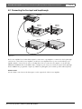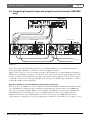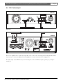
1
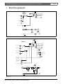
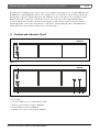
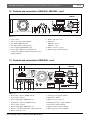
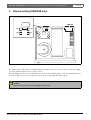
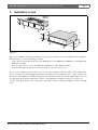
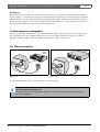
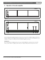
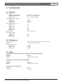
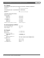
Plena Booster Amplifier
Installation and Operating Manual
en
LBB 1930, LBB 1935,
LBB 1938
Plena Booster Amplifier | Installation and Operating Manual | Important safeguards
en | 3
Important safeguards
1 Read instructions - All the safety instructions for use
should be read before the system is operated.
2 Retain instructions - The safety instructions and
instructions for use should be retained for future
reference.
3 Heed warnings - All warnings on the unit and in the
operating instructions should be adhered to.
4 Follow instructions - All operating instructions and
instructions for use should be followed.
5 Cleaning - Unplug system units from the mains outlet
before cleaning. Do not use liquid cleaners or aerosol
cleaners. Use a damp cloth for cleaning.
6 Attachments - Do not use attachments not
recommended by the product manufacturer as they may
cause hazards.
7 Water and Moisture - Do not use this unit near water, for
example near a bathtub, washbowl, kitchen sink, or
laundry basket, in a wet basement, near a swimming
pool, in an unprotected outdoor installation or any area
which is classified as a wet location.
8 Accessories - Do not place this unit on an unstable stand,
tripod, bracket or mount. This unit may fall, causing
serious injury to a person and serious damage to the
unit. Use only a stand, tripod, bracket or mount
recommended by the manufacturer, or sold with the
product. Any mounting of the unit should follow the
manufacturer's instructions, and should use a mounting
accessory recommended by the manufacturer. An
appliance and cart combination should be moved with
care. Quick stops, excessive force, and uneven surfaces
may cause the appliance and cart combination to
overturn.
9 Ventilation - Openings in the enclosure, if any, are
provided for ventilation and to ensure reliable operation
of the unit and to protect it from overheating. These
openings must not be blocked or covered. The unit
should not be placed in a built-in installation unless
proper ventilation is provided or the manufacturer's
instructions have been adhered to.
10 Power sources - Units should be operated only from the
type of power source indicated on the marking label. If
you are not sure of the type of power supply you plan to
use, consult your appliance dealer or local power
company. For units intended to operate from battery
power, or other sources, refer to the "Installation and
User Instructions".
11 Grounding or polarisation - This unit may be equipped
with a polarised alternating current line plug (a plug
having one blade wider than the other). This plug will fit
into the power outlet only one way. This is a safety
feature. If you are unable to insert the plug fully into the
outlet, try reversing the plug. If the plug still fails to fit,
contact your electrician to replace your obsolete outlet.
Do not defeat the safety purpose of the polarised plug.
Alternatively, this unit may be equipped with a 3-wire
grounding type plug having a third (grounding) pin.
This plug will only fit into a grounding-type power
outlet. This is a safety feature. If you are unable to insert
the plug into the outlet, contact your electrician to
replace your obsolete outlet. Do not defeat the safety
purpose of the grounding-type lug.
Bosch Security Systems | 2003-09 | 3922 988 92983en
12 Power-Cord Protection - Power supply cords should be
routed so that they are not likely to be walked on or
pinched by items placed upon or against them, paying
particular attention to cords and plugs, convenience
receptacles, and the point where they exit from the
appliance.
13 Overloading - Do not overload outlets and extension
cords as this can result in a risk of fire or electrical shock.
14 Object and Liquid Entry - Never push objects of any
kind into this unit through openings as they may touch
dangerous voltage points or short-out parts that could
result in a fire or electric shock. Never spill liquid of any
kind on the unit.
15 Servicing - Do not attempt to service this unit yourself as
opening or removing covers may expose to dangerous
voltage or other hazards. Refer all servicing to qualified
service personnel.
16 Damage Requiring Service - Unplug the unit from the
outlet and refer servicing to qualified service personnel
under the following conditions:
• When the power-supply cord or plug is damaged.
• If liquid has been spilled, or objects have fallen into
the unit.
• If the unit has been exposed to rain or water.
• If the unit does not operate normally by following
the instructions for use. Adjust only those controls
that are covered by the instructions for use, as an
improper adjustment of other controls may result in
damage and will often require extensive work by a
qualified technician to restore the units to their
normal operation.
• If the unit has been dropped or the unit has been
damaged.
• When the unit exhibits a distinct change in
performance; this indicates a need for service.
17 Replacement Parts - When replacement parts are
required be sure the service technician has used
replacement parts specified by the manufacturer or parts
which have the same characteristics as the original part.
Unauthorised substitutions may result in fire, electric
shock or other hazards.
18 Safety Check - Upon completion of any service or
repairs to the units, ask the service technician to perform
safety checks to determine that the unit is in proper
operating condition.
19 Lightning - For added protection of the units during a
lightning storm, or when it is left unattended and unused
for long periods of time, unplug it from the wall outlet
and disconnect the cable system. This will prevent
damage to the unit due to lightning and power-line
surges.
Plena Booster Amplifier | Installation and Operating Manual | About this manual
en | 4
About this manual
This manual provides all the information required to install and operate the unit.
Conventions
Warning
Follow these instructions to prevent personal injury.
Caution
Follow these instructions to prevent damage to the equipment.
Note
Read these instructions for tips and other useful information.
Safety precautions
Warning
Do not open the unit when it is connected to the mains. The unit contains non-insulated parts, which can
cause electric shock.
Caution
There are no user-serviceable parts inside the unit. Service must be done by qualified personnel.
Bosch Security Systems | 2003-09 | 3922 988 92983en
Plena Booster Amplifier | Installation and Operating Manual | Table of contents
en | 5
Table of contents
Important safeguards..........................................................................................................................................................3
About this manual ..............................................................................................................................................................4
Safety precautions...............................................................................................................................................................4
Table of contents ................................................................................................................................................................5
1 About the equipment ........................................................................................................................................................7
1.1
Controls and indicators (front) ................................................................................................................................8
1.2
Controls and connections (LBB1930, LBB1935 - rear) ........................................................................................9
1.3
Controls and connections (LBB1938 - rear) ...........................................................................................................9
2 Internal setting (LBB1938 only) .....................................................................................................................................10
3 Installation in rack ...........................................................................................................................................................11
4 External settings and connections .................................................................................................................................12
4.1
Connect the DC supply (battery) ..........................................................................................................................12
4.2
Connecting the line input and loopthrough ........................................................................................................13
4.3
Connecting the priority input and using the control terminals (LBB1938 only) .............................................14
4.4
100 V slave input ....................................................................................................................................................15
4.5
Connecting loudspeakers .......................................................................................................................................16
4.5.1 Constant voltage loudspeakers .........................................................................................................................16
4.5.2 Low impedance loudspeakers ..........................................................................................................................17
4.6
Mains connection ....................................................................................................................................................17
5 Operation of booster amplifier ......................................................................................................................................18
6 Technical data ..................................................................................................................................................................19
6.1
Electrical ..................................................................................................................................................................19
6.2
Performance ............................................................................................................................................................19
6.3
Inputs ........................................................................................................................................................................19
6.4
Outputs .....................................................................................................................................................................20
6.5
Environmental conditions ......................................................................................................................................20
6.6
General .....................................................................................................................................................................20
Bosch Security Systems | 2003-09 | 3922 988 92983en
Plena Booster Amplifier | Installation and Operating Manual | Table of Contents
Bosch Security Systems | 2003-09 | 3922 988 92983en
en | 6
Plena Booster Amplifier | Installation and Operating Manual | About the equipment
1
en | 7
About the equipment
VU
LBB1930
100V
Temp.
Sensor
LBB1935
70V
8Ohm
Input
0
0
Loopthrough
100V
Slave Input 100V
0
DC Fuse
Fuse
Power
230V
240V
Power
+
DC In 24V
-
Figure 1.1
Overheat
LBB1938
VU
100V
Temp.
Sensor
70V
8Ohm
Input 1 Priority
0
0
Loopthrough 1
Input 2 Program
100V
70V
F701
F702
Priority Only
Loopthrough 2
No Priority
0
0
Input 1 Priority
2..24V - Input 1
0V - Input 2
+
Input 2 Enable
2..24V - Enable
0V - Mute
+
-
-
100V
Slave Input 100V
0
Power
Inrush current
Fuse 10A limiter
230V
DC Fuse 40A
Power
Delay
+
DC In 24V
-
Figure 1.2
Bosch Security Systems | 2003-09 | 3922 988 92983en
Battery
Plena Booster Amplifier | Installation and Operating Manual | About the equipment
en | 8
The Plena Booster Amplifier range consists of three mono amplifiers with output powers of 120 W (LBB1930), 240
W (LBB1935) or 480 W (LBB1938). These booster amplifiers have 70 V and 100 V constant voltage outputs and a
low impedance output for 8 Ohm loudspeakers. The amplifiers are protected against overload and short circuits.
Built-in features like a temperature controlled fan and an overheat protection ensure high reliability. Battery
operation with automatic switchover from the mains supply is possible. The line inputs are balanced and have a
loopthrough facility; a 100 V slave input allows for connection to existing loudspeaker lines. The LBB1938 has
double inputs with a priority function and priority controlled outputs.
1.1 Controls and indicators (front)
LBB1930
LBB1935
2
Plena Booster Amplifier
0 dB
1
2
3
4
dB
VU-20-6meter
(LED bar)
dB
Power on indication LED (green)
Power
Power on/off
Tone control, channel 1 to 4
5
6
7
8
Volume, channel 1 to 4
Master volume
Channel selection for headphone
Headphone connection
1
Figure 1.3
2
LBB1938
Plena Booster Amplifier
0 dB
-6 dB
-20 dB
Battery
Overheat
Power
1
Figure 1.4
1
2
3
4
5
Power button
VU-meter (LED's for -20, -6, 0 dB and Power ON)
Battery operation indicator (only for LBB1938)
Overheat indicator (only for LBB1938)
Air inlet for forced air cooling (only for LBB1938)
Bosch Security Systems | 2003-09 | 3922 988 92983en
3
4
5
Plena Booster Amplifier | Installation and Operating Manual | About the equipment
en | 9
1.2 Controls and connections (LBB1930, LBB1935 - rear)
LBB1930
LBB1935
230V- 240V-
+
1
3
GND
2
GND
1
3
+
2
100V 70V
0
0
8
11
10
24V DC IN
+
9
100V 0V
Line fuse
250V T1A
line in
line out
Apparatus delivered
connected for 230V-
8
Warning
100V
This apparatus must be earthed
1
2
3
4
5
6
7
Figure 1.5
1
2
3
4
5
6
7
Level control
100 V / 0 V slave input terminal
Line input (XLR/balanced)
Line input (phone jack/balanced)
Line loopthrough (XLR/balanced)
Line loopthrough (phone jack/balanced)
Loudspeaker output terminals and 24 Vdc power
supply terminals
8 Earth connection screw
9 Mains fuse
LBB1930 T2.5A
LBB1935 T4A
10 Mains connector (3-pole)
11 Mains voltage switch 230/240 V
1.3 Controls and connections (LBB1938 - rear)
15 14 13
12
LBB1938
Inpu t 1 Priority
Input 1 Input 2 Slave Input
Priority Enable 100V
Loopthrough 1
Loopthrough 2
2..24V GND 2..24V GND 100V
Default Off Default On
Input 1-Priority
11
Input 2 Program
Input 1 Priority
2..24V-Input 1
0V-Inpu t 2
+
-
Inpu t 2 Enable
2..24V-Enable
0V-Mute
+
-
100V
0
70V
0
10
8ohm
Slave Input 100V100V
0
Direct O utput
100V/70V
0
100V 0
Priority Only
0
Input 2-Program
No Priority
0
70V 0
8
Priority ControlledO utput
Priority Only
No Priority
100V 0
100V 0
Priority
Input
Input
9
8
1
2
3
4
5
6
7
Figure 1.6
1
2
3
4
5
6
7
8
Priority line - input 1 (XLR/balanced)
Level control - input 1
Line loopthrough 1 (XLR/balanced)
Program line - input 2 (XLR/balanced)
Level control - input 2
Line loopthrough 2 (XLR/balanced)
Priority controlled loudspeaker output terminals
Earth connection screw
Bosch Security Systems | 2003-09 | 3922 988 92983en
9
10
11
12
13
14
15
24 Vdc power supply terminals
Mains fuse (T10A)
Mains connector (3-pole)
Loudspeaker direct output terminals
100 V slave input terminals
Input 2 enable control terminals
Input 1 priority control terminals
Plena Booster Amplifier | Installation and Operating Manual | Internal setting (LBB1938 only)
2
en | 10
Internal setting (LBB1938 only)
LBB1938
F701
100V
F702
70V
Figure 2.1
The output voltage of the priority controlled loudspeaker outputs can be set to 70 V or 100 V. To this end, a high
power fuse inside the unit is used as a voltage selector.
Insert the high power fuse into fuse holder F701 for 100 V selection (default setting), or into fuse holder F702 for 70
V selection. This selection does not affect the output voltage of the loudspeaker direct outputs.
Caution
Never insert two fuses into F701 and F702 simultaneously.
Bosch Security Systems | 2003-09 | 3922 988 92983en
Plena Booster Amplifier | Installation and Operating Manual | Installation in rack
3
en | 11
Installation in rack
LBB1930
LBB1935
Plena
0 dB
-6 dB
-20 dB
Boost
er Am
plifier
Power
1
1
LBB1938
Plena
Boost
er Am
0 dB
-6 dB
-20 dB
plifier
Power
1
Battery
Overhea
t
1
Figure 3.1
The booster amplifier is delivered for tabletop use, but you can mount it in a 19" rack using the brackets supplied
with the unit. In case of rack mounting, you must:
• remove the 4 feet from the bottom of the unit. Without the feet, the LBB1930 and LBB1935 are 2U high and the
LBB1938 is 3U high.
• leave 1U empty rack space above the LBB1930 or LBB1935 to ensure sufficient air flow.
• ensure that the ambient temperature of the unit in the rack does not exceed 55 °C.
In case of rack mounting, removal of the top cover of a booster amplifier is allowed to improve the ventilation. In
such a case, always use the shimming washers that come with the brackets and make sure to comply with the safety
instructions. The amplifier has a built-in temperature controlled fan for reliable operation at high output power for a
prolonged time. If the internal temperature reaches a critical limit due to insufficient air flow, overload or an
excessive ambient temperature, the overheat protection will be activated, causing the amplifier to switch to standby
mode.
Bosch Security Systems | 2003-09 | 3922 988 92983en
Plena Booster Amplifier | Installation and Operating Manual | External settings and connections
4
en | 12
External settings and connections
4.1 Connect the DC supply (battery)
Direc
100V
70V
0
230V
- 24
0V0
8
This
12 V
D
appara
C
0 70
V 0
8
Priori
ty Co
ntroll
Priori
ed Ou
ty on
tput
ly
No pri
ority
Line
fus
250V e
T1A
Appa
rat
conn us delive
ected
red
for 23
st be
0Vear the
d
100V
+
1
0V
3
GND
2
GND
1
3
00 V
+
2
100V
100V
line out
tus mu
+
8
70V
230V0
0
8
24V
-
12 V
D
+
0
240V-
10 0V
DC IN
Appa
rat
conne us delive
cted
red
for 23
0V-
Input
Input
2 Slave
Enable
Input
100V
1-Priorit
y
Input
2-Progra
m
Input
Direct
Output
Rated
power input
: 1600V
Loopthro
ugh
Input
Line
fus
T10L e
250V
Apparatu
connectes delivered
d for
230V-
100V
Loopthro
ugh
0 70V
0
8
Priority
Controll
Priority
ed Output
only
No priority
100V
24VDC
IN
0
100V
Line
fuse
T10L250
V
24VDC
IN
0
Warning
This
apparatu
s must
be earthed
0
+
Warni
ng
Line
fuse
250V
T1A
This
app
Warning
This
apparatus
must
Apparat
connectus delivere
ed for
d
230V-
be earthed
F
-
Rated
powe input
r : 16
00V
00 V
24V
DC IN
+
Warni
ng
Input
1
Priority
t Outpu
t
LBB1930 (120W); F=F15A
LBB1935 (240W); F=F30A
C
12 V
D
aratus
must
be
ear the
8
d
+
C
12 V
D
Figure 4.1
+
LBB1938 (480W); F=F40A
C
Figure 4.2
The booster amplifier has a 24 Vdc input (screw terminal), which you can use to connect a back up power supply,
e.g. batteries. You can earth (8) the unit to increase the electrical stability of the system.
Caution
The connection cable must have an in-line fuse. Use the type of fuse as mentioned in the illustration.
Bosch Security Systems | 2003-09 | 3922 988 92983en
Plena Booster Amplifier | Installation and Operating Manual | External settings and connections
en | 13
4.2 Connecting the line input and loopthrough
LBB1925/10
Tel/EM
/Line
G
Trigger
1
Trigger
2
LBB19
89001 25/00
115/2392500 05
No. 0V~,50/60Hz
0
1.Audi
2.0V o+ 5.Allca
3.Audi
6.Data ll
4.24Vdo- 7.Data.c. 8.Chs. +
GND
/Line
14
3
5
PCAud
ioIn
RS232
Zone
CD
3
1
5
2
5
L
4
Zone
2
6
8
5
2
1
R
3
Call
Active
GND
1
GND
1
-
+
100V
2
Zone
3
4
Maste
6
Aux
+
7
3
Appara
tus delivere
connec
d
ted for
In
230V- 115V-
In
100V
Zone
Zone
100V
3
Zone
0
4
100V
DC Out
0
100V
0
230V-
0
2
Out
100V
Call
0
1
rOut
100V
0
100V
0
DC In
0
+24V+24VRated
Warning
This
apparatu
s must
be earthed
input
Power
: 50VA
T1.0AL
250V
3 5
+
1
100V
0V
3
GND
2
GND
1
3
3 5
LBB1930
LBB1935
+
1
100V
+
2
0V
100V
100V
230V70V
0
0
24V
8
-
line out
3
GND
2
GND
1
3
+
2
100V
100V
240V-
LBB1930
LBB1935
230V70V
0
0
DC IN
+
8
24V
-
apparat
us must
4
+
Input
1
Priority
Line
fuse
250V
T1A
Warnin
g
This
Appara
conne tus deliver
cted
ed
for 230V-
apparat
us must
be earthed
LBB1938
Input
1
Priority
Input
Input
2
Enable Slave Input
100V
1-Prior
ity
Input
2-Prog
ram
Input
Direct
Output
Rated
power input
: 1600V
Loopth
rough
Input
Appara
connectus deliver
ed
ted for
230V-
0 70V
0
8
Priority
Contro
Priority
lled Output
only
No priority
100V
2-Prog
ram
Input
Direct
0
Rated
power input
: 1600V
24VDC
IN
0 70V
0
8
Priority
Contro
Priority
lled Output
only
No priority
100V
100V
0
Warnin
g
This
appara
tus must
Appara
connectus deliver
ed
ted for
230V-
100V
Loopth
rough
Line
fuse
T10L25
0V
Output
Loopth
rough
Input
100V
Loopth
rough
LBB1938
4 6
Input
2
Enable Slave Input
100V
1-Prior
ity
Input
Appara
conne tus deliver
cted
ed
for 230V-
be earthed
4 6
6
4 6
Input
240V-
DC IN
line out
Line
fuse
250V
T1A
Warnin
g
This
0
100V
Line
fuse
T10L25
0V
24VDC
IN
0
Warnin
g
This
be earthed
appara
tus must
be earthed
Figure 4.3
The booster amplifier has a balanced line input for connection to a preamplifier or a mixer. Use the loopthrough
connection to connect the booster amplifier to another booster amplifier if more power is needed. Each power
amplifier must be connected to its own set of loudspeakers. Do not connect booster outputs to each other. The
LBB1930 and LBB1935 have both XLR (3 and 5) and phone jack connectors (4 and 6) for input and loopthrough.
For the LBB1938 use program line - input 2 (4) and line loopthrough 2 (6) for normal operation without priority.
Volume control
Use the volume control next to the line input to set the output level of the booster amplifier.
Bosch Security Systems | 2003-09 | 3922 988 92983en
Plena Booster Amplifier | Installation and Operating Manual | External settings and connections
en | 14
4.3 Connecting the priority input and using the control terminals (LBB1938
only)
LBB1925/10
Tel/EMG
Trigger 1
Trigger 2
Apparatus delivered
connected for 230V-
LBB1925/10
890019251005
115/230V~,50/60Hz
No.
115V
230V
0
5. Allcall
6.DataPCAudoln
7.Data+
8.Chs.GND
1. Audio+
2.0V
3.Audio4.24Vd.c.
/Line
RS232
CD
Aux
L
/Line
+
2
3
R
7
14
3
5
3
1
5
3
GND
1
1
100V 0
100V 0
100V 0
1
4
2
100V 0
MasterOut
100V 0
100V 0
100V 0
Out
LBB1938
14
LBB1938
Input 1 Prior ity
Input 1 Input 2 Slave Input
Priority Enable 100V
Loopthrough 1
Input 2 Program
Loopthrough 2
Input 1-Priority
Input 1 Prior ity
2..24V-Input 1
0V-Input 2
+
-
Input 2 Enable
2..24V-Enable
0V-Mute
+
-
Slave Input 100V 100V
0
0
100V
0
70V
0
Loopthrough 1
Input 2 Program
Loopthrough 2
Direct Output
8ohm
100V/70V
100V 0
Priority Only
0
Input 2-Program
No Pr iority
0
70V 0
8
Priority Controlled Output
Priority Only
2...24VGND 2...24VGND 100V
Default Off Default On
Input 1-Priority
Input 1 Prior ity
2..24V-Input 1
0V-Input 2
+
-
Input 2 Enable
2..24V-Enable
0V-Mute
+
-
Slave Input 100V 100V
0
0
Direct Output
8ohm
100V 0
Priority Only
0
Input 2-Program
No Pr iority
0
70V 0
8
Priority Controlled Output
Priority Only
No Priority
100V 0
100V 0
Priority
100V 0
1
100V
0
70V
0
100V/70V
No Priority
Priority
Input
Rated Input
Power : 50VA
T0.5L 250V
Zone 2 output
15
Input 1 Prior ity
2...24VGND 2...24VGND 100V
Default Off Default On
+24VWarning
This apparatus must be earthed
Zone 1 output
Input 1 Input 2 Slave Input
Priority Enable 100V
+24V-
2
14
15
100V 0
+
3
6
8
5
4
2
GND
100V 0
Input
4
Input
1
Input
4
to next zones
Figure 4.4
Next to the program input (Input 2-Program) the booster amplifier LBB1938 is also provided with a balanced
priority input (Input 1-Priority) for connection to another preamplifier or mixer.
Apply a control voltage of 2...24 V to the input 1 priority control terminals (15) to switch ON the priority input (1)
and mute the program input (4). In this way a local music source can be connected to the program input and a remote
emergency system to the priority input. The emergency source must be able to supply the 2…24 V control voltage to
override the local music source. The program input can be remotely controlled by using a switch that is connected
to the input 2 enable control terminals (14).
Application example for use of the LBB1938 control terminals (see fig. 4.4)
You can use up to six LBB1938 boosters in combination with the Plena LBB1925/10 System Pre-amplifier to build
a powerful multi-zone sound system. Zone switching of background music and calls is done via the LBB1925/10
zone relays in combination with the LBB1938 control terminals. The LBB1925/10 controls the background music
by distributing 24 Vdc via the music zone relays to the LBB1938 input 2 enable control terminals (14). The
LBB1925/10 controls the calls by distributing 24 Vdc via the call zone relays to the LBB1938 input 1 priority
control terminals (15). Each booster serves one loudspeaker zone. Each zone can be OFF, or receive music or a call.
Bosch Security Systems | 2003-09 | 3922 988 92983en
Plena Booster Amplifier | Installation and Operating Manual | External settings and connections
en | 15
4.4 100 V slave input
LBB1930
LBB1935
230V- 240V-
+
1
3
GND
2
GND
1
3
24V DC IN
+
+
2
100V 70V
0
0
8
100V 0V
line in
Line fuse
250V T1A Apparatus delivered
connected for 230V-
line out
Warning
100V
This apparatus must be earthed
Figure 4.5
15 14
13
LBB1938
Input 1 Priority
Input 1 Input 2 Slave Input
Pr iority Enable 100V
Loopthrough 1
Input 2 Program
Loopthrough 2
2..24V GND 2..24V GND 100V
Default Off Default On
Input 1-Pr iority
Direct O utput
Input 1 Priority
2..24V-Input 1
0V-Input 2
+
-
Input 2 Enable
2..24V-Enable
0V-Mute
+
-
SlaveInput 100V 100V
0
0
100V
0
70V
0
8ohm
100V/70V
100V 0
Priority Only
0
Input 2-Program
No Priority
0
70V 0
8
Priority Controlled O utput
Priority Only
No Priority
100V 0
100V 0
Priority
Input
Input
Figure 4.6
The booster amplifiers have a 100 V slave input that can be connected to an existing 100 V loudspeaker line. In this
way it is easy to connect an additional booster amplifier on a remote location for more output power.
The 100 V input of the LBB1938 (13) is not affected by the control terminals for input 1 priority (15) or input 2
enable (14).
Bosch Security Systems | 2003-09 | 3922 988 92983en
Plena Booster Amplifier | Installation and Operating Manual | External settings and connections
en | 16
4.5 Connecting loudspeakers
LBB1930
LBB1935
VU
LBB1930
LBB1935
100V
70V
8Ohm
+
1
100V
0V
3
GND
2
GND
1
3
+
2
100V
100V
230V70V
0
0
8
line out
24V
-
240V-
DC IN
+
Line
fuse
250V
T1A
Warnin
g
This
0
0
100V 70V
0
0
24V DC IN
+
8
apparat
us must
Appar
atus
delive
conne
red
cted
be earthed
for 230V-
Figure 4.7
8 Ohm
4 Ohm
4 Ohm
100 V
8 Ohm
8 Ohm
8 Ohm
8 Ohm
70 V
8 Ohm
Figure 4.9
8 Ohm
LBB1938
VU
100V
70V
8Ohm
100 V
8 Ohm
8 Ohm
8 Ohm
8 Ohm
4 Ohm
70 V
4 Ohm
LBB1938
8 Ohm
0
0
100V
70V
F701
F702
Input
1
Priorit
y
Input
Input
2
Enable Slave
Input
100V
1-Prio
rity
Input
2-Prog
ram
Input
Direct
Loopt
hroug
h
Outpu
t
Rated
power input
: 1600V
Appara
connectus delivere
ted for
d
230V-
Input
100V
Loopt
hroug
h
0 70V
0
8
Priorit
y Contr
Priorit
olled
Outpu
y only
No priority t
Line
fuse
T10L25
0V
24VDC
IN
100V
0
100V
0
Warnin
This
g
apparat
us must
be earthed
Direct Output
Priority Only
No Priority
100V 0
0
0
Figure 4.8
70V 0
8
Priority Controlled Output
Priority Only
No Priority
100V 0
100V 0
Priority Only No Priority
Figure 4.10
4.5.1 Constant voltage loudspeakers
The booster amplifier can drive 100 V constant voltage loudspeakers at full power (100 V) or half power (70 V).
Connect the loudspeakers in parallel and check the loudspeaker polarity for in-phase connection. The summed
loudspeaker power should not exceed the rated amplifier power.
Bosch Security Systems | 2003-09 | 3922 988 92983en
Plena Booster Amplifier | Installation and Operating Manual | External settings and connections
en | 17
LBB1938 only:
Ensure that the fuse for loudspeaker voltage selection is properly set (see chapter 2). The Priority Only and No
Priority outputs are controlled by a priority relay. The Priority Only output only provides priority announcements,
while the No Priority output just provides the program signal and switches OFF at priority calls. You can also use
the Priority Only output for 3-wire remote volume control override. In this case, ensure that the selected voltage for
the Priority Only output is the same as for the direct output used.
4.5.2Low impedance loudspeakers
Connect low impedance loudspeakers to the 8 Ohm/0 terminals. This output can deliver the rated output power
into an 8 Ohm load. Connect multiple loudspeakers in a series/parallel-arrangement to make the combined
impedance 8 Ohm or higher. Check the loudspeaker polarity for in-phase connection.
4.6 Mains connection
LBB1938
LBB1930
LBB1935
Input
1
Priority
Input
2
Enable Slave
Input
100V
Input
1-Prior
ity
Input
Tel/Eme
0 r.
0 2
Input
Direct
Loopth
rough
CD
Outpu
t
Rated
power input
: 1600V
Out
Chime
Apparat
connec us delivere
ted for
d
230V-
Input
Aux
1- -3
4 .5
11
2-Prog
ram
L
R
Line
100V
Out 1V
Mic/Lin
1
Loopth
rough
In
Inc
e
Mic/Lin
2
e
100V
3
4
230V70V
0
0
8
240V-
0 70V
0
8
Priority
Contro
Priority
lled Outpu
only
No priority t
100V
24V
- DC IN
+
0
100V
Line
fuse
T10L25
0V
24VD
C IN
0
Warning
This
70V
0
230V
- 24
0V0
8
apparatu
s must
be earthed
Line
fuse
250V
T1A
Warning
This
apparatu
s must
Appara
connectus delivere
ted for
d
230V-
be earthed
24V
DC IN
+
Line
fus
250V e
T1A
Warni
Appa
ng
rat
This
conn us delive
appara
ected
red
tus mu
for 23
st be
earthe
0Vd
Direct
Outpu
t
Rated
powe input
r : 16
00V
V 0
70 V
0
8
Prior
ity Co
ntrolle
Prior
d Out
ity on
put
ly
No pr
iority
V 0
10 0V
Appa
rat
conn us delive
ected
red
for 23
0V-
Line
fus
T10L e
250V
24VD
C IN
0
Warn
ing
This
ap
Figure 4.11
parat
us mu
st be
earth
ed
Figure 4.12
Use the supplied mains cord to connect the system to the mains supply.
Note (LBB 1930 and LBB 1935 only)
If necessary set the mains voltage switch 230/240 V (11) to the required voltage using a sharp object,
e.g. a small screwdriver.
Bosch Security Systems | 2003-09 | 3922 988 92983en
Plena Booster Amplifier | Installation and Operating Manual | Operation of booster amplifier
5
en | 18
Operation of booster amplifier
LBB1930
LBB1935
2
Plena Booster Amplifier
0 dB
-6 dB
-20 dB
Power
1
Figure 5.1
2
LBB1938
Plena Booster Amplifier
0 dB
-6 dB
-20 dB
Battery
Overheat
Power
1
3
4
5
Figure 5.2
Upon switching ON the amplifier using the power button (1), the green Power On LED (2) lights up. The VU-bar
shows the output level of the amplifier. If the internal temperature of the booster reaches a critical limit, due to poor
ventilation or overload, an overheat protection circuit switches OFF the power stage.
LBB1938 only:
The overheat indicator (4) lights up if the power stage is switched OFF by the overheat protection circuit. The
battery operation indicator (3) lights up if the mains power supply is failing and the back-up battery is in use.
Bosch Security Systems | 2003-09 | 3922 988 92983en
Plena Booster Amplifier | Installation and Operating Manual | Technical data
6
Technical data
6.1 Electrical
Mains voltage
LBB1930/00, LBB1935/00
LBB1930/50, LBB1935/50
LBB1938/00
Max mains power consumption
LBB1930/x0
LBB1935/x0
LBB1938/00
Max mains inrush current
LBB1930/00
LBB1930/50
LBB1935/00
LBB1935/50
LBB1938/00
Battery voltage
Max battery current
LBB1930/x0
LBB1935/x0
LBB1938/00
230/240 Vac, ±10%, 50/60 Hz
110 Vac, ±10%, 50/60 Hz
230 Vac, ±10%, 50/60 Hz
400 VA
800 VA
1600 VA
8A
16 A
9A
19 A
19 A
24 Vdc, +20%/-10%
6A
11 A
30 A
6.2 Performance
Frequency response
Distortion
S/N (flat at max volume)
LBB1930/x0
LBB1935/x0
LBB1938/00
50 Hz - 20 kHz (+1/-3 dB @ -10 dB ref. rated output)
< 1% @ rated output, 1 kHz
> 80 dB
> 85 dB
> 90 dB
6.3 Inputs
Line input (3-pin XLR, 6.3 mm phone jack, balanced) - LBB1930/x0, LBB1935/x0
Sensitivity
1V
Impedance
20 kOhm
CMRR
> 25 dB (50 Hz - 20 kHz)
Line input 1, 2 (3-pin XLR, balanced) - LBB1938/00
Sensitivity
1V
Impedance
20 kOhm
CMRR
> 25 dB (50 Hz - 20 kHz)
100 V input (Screw, unbalanced)
Sensitivity
Impedance
100 V
330 kOhm
Bosch Security Systems | 2003-09 | 3922 988 92983en
en | 19
Plena Booster Amplifier | Installation and Operating Manual | Technical data
6.4 Outputs
Line loopthrough output (3-pin XLR, 6.3 mm phone jack, balanced) - LBB1930/x0, LBB1935/x0
Nominal level
1V
Impedance
direct connection to line input
Line loopthrough output 1, 2 (3-pin XLR, balanced) - LBB1938/00
Nominal level
1V
Impedance
direct connection to line input
Loudspeaker outputs (Screw, floating)
Max/rated output power
70/100 V output
LBB1930/x0
LBB1935/x0
LBB1938/00
8 Ohm output
LBB1930/x0
LBB1935/x0
LBB1938/00
Output power @ 24 V battery operation
180 W/120 W
360 W/240 W
720 W/480 W
31 V (120 W)
44 V (240 W)
62 V (480 W)
-1 dB ref. rated power
6.5 Environmental conditions
Operating temperature range
Storage temperature range
Relative humidity
-10 to +55 °C
-40 to +70 °C
< 95%
6.6 General
EMC emission
EMC immunity
Acoustic noise level of fan
LBB1930/x0, LBB1935/x0
LBB1938/00
Dimensions
LBB1930/x0, LBB1935/x0
LBB1938/00
Weight
LBB1930/x0
LBB1935/x0
LBB1938/00
19” mounting brackets
acc. to EN 55103-1
acc. to EN 55103-2
< 45 dB SPL @ 1 m
< 48 dB SPL @ 1 m
100 x 430 x 270 mm (19” wide, 2U high, with feet)
145 x 430 x 370 mm (19” wide, 3U high, with feet)
approx. 10.5 kg
approx. 12.5 kg
approx. 25 kg
included
Bosch Security Systems | 2003-09 | 3922 988 92983en
en | 20
For more information visit
www.boschsecuritysystems.com
© Bosch Security Systems B.V.
Data subject to change without notice
2003-09 | 3922 988 92983en