1
AV SURROUND
RECEIVER
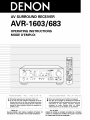
AVR- 1603/683
OPERATING INSTRUCTIONS
MODE D'EMPLOI
.---
,7
--
.-
DTS
DUD
©
O
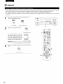
FOR ENGLISH READERS
•
•
©©©
PAGE
2 -
PAGE
53, 104 ~ I08
POURLESLECTEURSFRANCAIS
We greatly appreciate your purchase of this unit.
TO be sure you take maximum advantage of all the
features this unit has to offer, read these instructions
carefully and use the set properly. Be sure to keep this
manual for future reference should any questions or
problems arise.
"SERIAL
PLEASE
NO.
RECORD
•
•
SERIAL
THE REAR OF THE CABINET
NUMBER
FOR FUTURE
ATTACHED
REFERENCE"
TO
PAGE
2,54-
PAGE
108
NOUS vous remercions pour I'achat de cet appareiL
Pour _tre s_r de profiter au maximum de toutes les
cerect6ristiques qu'offre cet appareil, lire avec soin ces
instructions
et bien utiliser
I'appareiL
Toujours
conserver
ce mode
d'emploi
pour
s'y r6f_rer
ult6rieurement
en cas de question ou de probl_me.
"NO.
UNiT
©
©©©
DE SERIE
PRIERE DE NOTER
LE NUMERO
DE SERIE DE L'APPAREIL
tNSCRIT A L'ARRIERE DU COFFRET DE FA(_ON A POUVOIR
LE CONSULTER EN CAS DE PROBLEME."
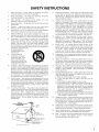
• SAFETY PRECAUTIONS
CAUTION
TO PREVENT ELECTRIC SHOCK, MATCH WIDE BLADE OP PLUG
TO WIDE SLOT, FULLY INSERT.
CAUTION:
The
_1_
ATTENTION
TO REDUCE THE RISK OF ELECTRIC SHOCK,
DO NOT REMOVE COVER (OR BACK)= NO
USER-SERVICEABLE
PARTS INSIDE. REFER
SERVICING
TO
QUALIFIED
SERVICE
PERSONNEL.
arrowhead
symbol,
presence
equilateral
product's
of uninsulafed
"dangerous
triangle,
is intended
to
enclosure
that
may be of
voltage"
alert
the
sufficient
constitute
a risk of electric
The
lightning
flash
exclamation
to
maintenance
aler[ the
shock
within
the
within
within
user
to
magnitude
an
the
the
to
to persons¸
an equilateral
This
device
the
following
complies
including
is intended
This
the
operating
literatureand
with
two
interference,
triangle
user (servicing)
to the presence
instructions
of impor[ant
in
accompanying
WARNING:
point
with
POUR EVITER LES CHOCS ELECTRIQUES, INTERODUIRE LA
LAME LA PLUS LARGE DE LA FICHE DANS LA BORNE
CORRESPONDANTE DE LA PRISE ET POUSSER JUSQU' AU
POND.
and
(2) this
interference
CJass
B digital
Interference-Causing
appliance¸
TO REDUCE THE RISK OF FIRE OR ELECTRIC
SHOCK, DO NOT EXPOSE THIS APPLIANCE
TO RAIN OR MOISTURE.
• NOTE ON USE / OBSERVATIONS
Cat
appareil
Reglement
15 of the
(1)
device
that
may
FCC
This
must
cause
accept
meets
Regulations
de
la dasse
brouilleur
all
Operation
may
any
undesired
apparatus
le matebel
Rules
device
Equipment
numebque
sur
Par[
conditions:
not
is subject
cause
interference
fecewed,
operation
requirements
B respecte
of
toutes
the
les
Canadian
exigences
du Canada
RELATIVES A L'UTILISATION
,%,
•
•
Avoid high temperatures
Allow
for suffcient
heat
installed
on a rack
Eviter
des temperatures
Ten[r
compte
suffisante
d'une
dispersion
•
Keep
dust
the
•
Proteger
poussiere
lots de Hnstallat[on
de
2
contre
water,
I'humidd6,
and
•
DO not
•
Ne pas
I'appareil
let foreign
•
DO not let insecticides,
benzene,
come in contact with the set
•
Ne pas mettre en contact des insecticides,
benz&ne et un di[uant avec I'appareil
•
Never
•
way
Ne jama[s
d_monter
ou modifier
d'une maniere ou d'une autre
la[sser
objects
des
in the set
objets
6trangers
dans
I'eau et la
chaleur
Handle the power cord carefully
Hold the plug when unplugging
the cord
Manpuler
le cordon
d'alimentation
Ullplug the p0wer cord when not us ng the set
for 10rig periods of time
Debrancher
le cordon
d'almentation
Iorsque
n'est
pas utilise
du
d6branchement
pendant
ventilati0n
holes)
du
•
Do not obstruct
the ventlat
•
Ne pas obstruer
les trous
0n holes
d'aeration
and
thinner
du
de Iongues
avec
* (For sets with
Iors
moisture,
sur une _tag_re
I'appareil
periodes
pr6caut on
Tenir
la prise
cordon
I'appareil
from
_lev_es
dispersion
•
•
free
when
•
•
set
disassemble
to
harmful
or modi_
the
set
in any
I'appareil
du
SAFETY INSTRUCTIONS
1.
Read Instructions - All the safety and operating
should be read before the product is operated.
instructions
13.
Power-Cord Protection - Power-supply cords should be routed
so that they are not likely to be walked on or pinched by items
placed upon or against them, paying particular attention to
cords at plugs, convenience receptacles, and the point where
they exit from the product.
2.
Retain Instructions - The safety and operating
should be retained for future reference.
instructions
3.
Heed Warnings - All warnings on the product
operating instructions should be adhered to.
and in the
4.
Follow Instructions
be followed.
15.
Outdoor Antenna Grounding - If an outside antenna or cable
system is connected to the product, be sure the antenna or
cable system is grounded so as to provide some protection
against voltage surges and built-up static charges. Article 810
of the National Electrical Code, ANSl/NFPA 70, provides
information with regard to proper grounding of the mast and
supporting structure,
grounding of the lead-in wire to an
antenna discharge unit, size of grounding conductors, location
of antenna-discharge unit, connection to grounding electrodes,
and requirements for the grounding electrode. See Figure A.
5.
Cleaning - Unplug this product from the wall outlet before
cleaning. Do not use liquid cleaners or aerosol cleaners.
6.
Attachments - Do not use attachments not recommended
the product manufacturer as they may cause hazards.
7.
Water and Moisture - Do not use this product near water - for
example, near a bath tub, wash bowl, kitchen sink, or laundry
tub; in a wet basement; or near a swimming pool; and the like.
16.
Lightning - For added protection for this product during a
lightning storm, or when it is left unattended and unused for
long periods of time, unplug it from the wall outlet and
disconnect the antenna or cable system.
This will prevent
damage to the product due to lightning and power line surges.
17.
Power Lines - An outside antenna system should not be
located in the vicinity of overhead power lines or other electric
light or power circuits, or where it can fall into such power lines
or circuits.
When installing an outside antenna system,
extreme care should be taken to keep from touching such
power lines or circuits as contact with them might be fatal.
18.
Overloading - Do not overload wall outlets, extension cords, or
integral convenience receptacles as this can result in a risk of
fire or electric shock.
19.
Object and Liquid Entry - Never push objects of any kind into
this product through openings as they may touch dangerous
voltage points or short-out parts that could result in a fire or
electric shock. Never spill liquid of any kind on the product.
10. Ventilation - Slots and openings in the cabinet are provided for
20.
ventilation and to ensure reliable operation of the product and to
protect it from overheating, and these openings must not be
blocked or covered. The openings should never be blocked by
placing the product on a bed, sofa, rug, or other similar surface.
This product should not be placed in a built-in installation such
as a bookcase or rack unless proper ventilation is provided or
the manufacturer's instructions have been adhered to.
Servicing - Do not attempt to service this product yourself as
opening or removing covers may expose you to dangerous
voltage or other hazards.
Refer all servicing to qualified
service personnel
21.
Damage Requiring Service - Unplug this product from the
wall outlet and refer servicing to qualified service personnel
under the following conditions:
a) When the power-supply cord or plug is damaged,
b) If liquid has been spilled, or objects have fallen into the
product,
c) If the product has been exposed to rain or water,
d) If the product does not operate normally by following the
operating instructions.
Adjust only those controls that are
covered by the operating
instructions
as an _mproper
adjustment of other controls may result in damage and will
often require extensive work by a qualified technician to
restore the product to its normal operation,
e) If the product has been dropped or damaged in any way, and
f) When the product exhibits a distinct change in performance
- this indicates a need for service.
22.
Replacement Parts - When replacement parts are required, be
sure the service technician
has used replacement
parts
specified by the manufacturer or have the same characteristics
as the original part. Unauthorized substitutions may result in
fire, electric shock, or other hazards.
23.
Safety Check- Upon completion of any service or repairs to this
product, ask the service technician to perform safety checks to
determine that the product is in proper operating condition.
24.
Wall or Ceiling Mounting - The product should be mounted to a
wall or ceiling only as recommended by the manufacturer.
25.
Heat- The product should be situated away from heat sources
such as radiators, heat registers, stoves, or other products
(including amplifiers} that produce heat.
8.
g.
- All operating and use instructions
should
by
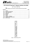
Accessories - Do not place this product on an unstable cart,
stand, tripod, bracket, or table. The product may fall, causing
serious injury to a child or adult, and serious damage to the
product.
Use only with a cart, stand, tripod, bracket, or table
recommended
by the manufacturer, or sold with the product.
Any mounting of the product should follow the manufacturer's
instructions, and should use a
mounting accessory
recommended by the
manufacturer.
A product and cart
combination should be
moved with care. Quick
stops, excessive force,
and uneven surfaces may
cause the product and cart
combination to overturn.
11.
Power Sources - This product should be operated only from the
type of power source indicated on the marking label, if you are
not sure of the type of power supply to your home, consult your
product dealer or local power company. For products intended
to operate from battery power, or other sources, refer to the
operating instructions.
12.
Grounding or Polarization - This product may be equipped with
a polarized alternating-current line plug (a plug having one blade
wider than the other). This plug will fit into the power outlet
only one way. This is a safety feature. If you are unable to
insert the plug fully into the outlet, try reversing the plug. If the
plug should still fail to fit, contact your electrician to replace your
obsolete outlet.
Do not defeat the safety purpose of the
polarized plug.
{NEC ART 25& PART H}
NEC._ATIONALELECTR_CALCODE
3
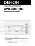
• INTRODUCTION
Thank you for choosing the DENON AN Surround receiver. This remarkable component has been engineered to provide superb surround sound
listening with home theater sources such as DVD, as well as providing outstanding high fidelity reproduction of your favorite music sources.
As this product is provided with an immense array of features, we recommend that before you begin hookup and operation that you review the
contents of this manual before proceeding.
TABLE OF CONTENTS
Before Using ..............................................................................................
4
@ Remote Control Unit ..........................................................................
Cautions on Installation
24~28
..............................................................................
5
Operation
...........................................................................................
29~33
Cautions on Handling .................................................................................
5
Surround .............................................................................................
34~39
5
DSP Surround Simulation ...................................................................
40~44
Listening to the Radio ............................................................
45-47
Features ......................................................................................................
Par[ Names and Functions .....................................................................
6, 7
Read this first .............................................................................................
8
Last Function
Setting up the Speaker Systems ................................................................
8
Initialization
Connections
.........................................................................................
9-15
Using the Remote Control Unit ................................................................
Setting upthe
Additional
16
System .......................................................................
of the Microprocessor
Information
Troubleshooting
17-23
Memory .............................................................................
Specifications
48
.................................................
........................................................................
48
49-51
........................................................................................
52
............................................................................
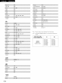
List of Preset Codes ..............................................................................
53
104~ 108
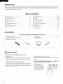
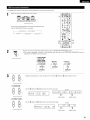
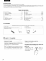
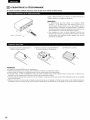
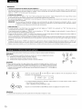
• ACCESSORIES
Check that the following
parts are included
0} Operating instructions ............................................................................
C2)Wananty ( for North Amedca model only ) ............................................
_ Service station list ...................................................................................
_4_ Remote control unit (RC-920} .................................................................
1
1
1
1
in addition to the main unit:
R6P/AA batteries ....................................................................................
2
AM loop antenna ....................................................................................
FM indoor antenna ..................................................................................
1
1
• Store this instructions
in e safe place.
After reading, store this instructions along with the warranty
safe place.
in a
®
[]
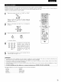
BEFORE USING
Pay attention
to the following
before using this unit:
• Moving the set
TOprevent short circuits or damaged wires in the connection
cords,
always unplug the power cord and disconnect the connection
cords between all other audio components when moving the set.
• Before turning the power operation switch on
Check once again that all connections are proper and that there are
not problems with the connection cords. Always set the power
operation switch to the standby position before connecting and
disconnecting connection cords.
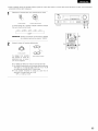
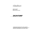
• Note that the illustrations
in this instructions
the actual set for explanation purposes.
• V. AUX terminal
The AVR-1603/683'S front
panel is equipped with a V.
AUX terminal. Remove the
cap covering the terminal
when you want to use it.
4
may differ from
....
--6---
[]
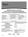
CAUTIONS
////////////////////////////////////////////////
ON INSTALLATION
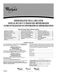
Noise or disturbance of the picture may be generated if this unit or
any other electronic equipment using microprocessors is used near a
tuner or TV.
_
oo_ooo
If this happens, take the following steps:
• Install this unit as far as possible from the tuner or TV.
• Set the antenna wires from the tuner or TV away from this unit's
power cord and input/output connection cords.
• Noise or disturbance tends to occur particularly when using indoor
antennas or 300 _2/ohms feeder wires. We recommend using
outdoor antennas and 75 _/ohms coaxial cables.
0 3 ft {/0 am) or more
0 o _ _....
_
I0_ °
_/X///XXX//XXXX//XXX//XXXX/XXX///XX////X////XX/,
0 3 ft (10 cm) or more
For heat dispersal, leave at least 0.3 ft (10 cm) of space between
the top, back and sides of this unit and the wall or other
components.
[]
CAUTIONS
ON HANDLING
• Switching
the input
function when input
jacks
connected
A clicking noise may be produced if the input function is
when nothing is connected to the input jacks, if this
either turn down the MASTER VOLUME control or
components
are
not
switched
happens,
connect
• Whenever the power operation switch is in the STANDBY
state, the apparatus
is still connected on some AC line
voltages.
Please be sure to unplug the cord when you leave home for,
say, a vacation.
to the input jacks.
• Muting of PRE OUT
terminals
jack,
HEADPHONE
jack and SPEAKER
The PRE OUT jack, HEADPHONE jack and SPEAKER terminals
include a muting circuit. Because of this, the output signals are
greatly reduced for several seconds after the power operation
switch is turned on or input function, surround mode or any other
set-up is changed.
If the volume is turned up during this time, the output will be very
high after the muting circuit stops functioning. Always wait until
the muting circuit turns off before adjusting the volume.
_'1
FEATURES
1. Dolby Pro Logic 11decoder
Dolby Pro Logic 1[ is a new format for pJaying mu]tichannel audio
signals that offers improvements
over conventional
Dolby Pro
Logic. It can be used to decode not only sources recorded in
Dolby Surround but also regular stereo sources into five channels
(front left/bght, center and surround left/right). In addition, various
parameters can be set according to the type of source and the
contents, so you can adjust the sound field with greater precision.
2. Dolby Digital decoder
Dolby Digital, a digital discrete system in which the different
channels
are completely
independent,
recreates
"three
dimensional"
sound fields (sounds with a sense of distance,
movement and position} with no crosstalk between channels for
greater reality, in addition, the 5 channels (excluding the 0.1
channel for low frequency
effects) have a playback range
extending to 20 kHz, the same as the range of CDs, thus resulting
in clearer, more richly expressive sound.
3. DTS (Digital Theater Systems)
DTS provides up to 5.1 channels of wide-range, high fidelity
surround sound, from sources such as laser disc, DVD and
specia/y encoded music discs.
4. High performance DSP simulates 7 sound fields
Playback is possible in 7 surround modes: 5-channel Stereo, Mona
Movie, Rock Arena, Jazz Club, Video Game, Matrix and Virtual.
You can enjoy a variety of sound effects for different
scenes and program sources even with stereo sources
Dolby Surround.
movie
not in
5. Personal Memory Plus function
Personal Memory
Plus is an advanced version of Personal
Memory. With Personal Memory Plus, the set automatically
memorizes
the surround
mode, channel volume,
surround
parameters, etc., for each of the separate input sources.
6. Remote
This unit
memory
DENON
control unit with pre-memory function
comes with a remote control unit equipped with a profunction.
The remote control command codes for
remote controllable AV components as well as for LD
players, video decks, TVs, etc., of other major manufacturers
prestored in the memory.
are
7. 6CH EXT. IN jacks
This unit is equipped with 6CH EXT. IN jacks for use with audio
formats of the future.
5
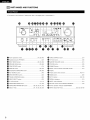
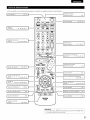
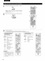
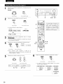
[]
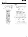
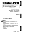
PART NAMES
AND FUNCTIONS
• For details on the functions of these parts, refer to the pages given in parentheses
O
Power operation switch ..............................................
O
Headphones
(18, 29, 45)
jack {PHONES} ....................................................
INPUT MODE button ...................................................
6
{35)
_)
MASTER VOLUME control ......................................................
{31)
(29, 48)
_}
STATUS button ........................................................................
{32)
{31)
_)
DIMMER
{32)
............................................................
button ......................................................................
(30, 33)
Master volume indicator {VOLUME
DOLBY/DTS SURROUND
(36, 38)
Display
button ......................................
LEVEL} ............................
..............................................................
{40)
_}
Preset station select buttons ............................................
DIRECT/STEREO button ..........................................................
{40)
_}
BAND button ...........................................................................
TUNING UP/DOWN
{46)
buttons ....................................................
VIDEO SELECT button ............................................................
_}
{31)
CH VOL button ........................................................................
ANALOG button ................................................................
8CH STEREO button
_}
TONE CONTROL button ..........................................................
(30, 33, 38)
SPEAKER A!B buttons .......................................................
TONE DEFEAT button
{32)
().
{32)
EXT. IN button ...................................................................
_}
{31}
(45, 47)
{46)
(30, 33)
SIGNAL indicators ....................................................................
(31)
INPUT mode indicators ............................................................
{31)
V. AUX terminals ..................................................................
(4, 11)
SURROUND MODE button ...............................................
(31, 43)
_)
Remote control sensor {REMOTE SENSOR) .......................... (16)
SURROUND PARAMETER button .................. (36, 38, 39, 41, 43)
_)
Power operation indicator (ON/STANDBY}
SELECT knob ..................................................
_)
INPUT SELECTOR knob ........................................
(31, 34, 36, 36, 43}
{30, 36, 38, 46)
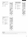
• For detaiEs on the functions of these parts, refer to the pages given in parentheses
I LED {indicator)
.............................
(25, 28)
().
/
I
.......
1
OlRE_r
_
SURROUND
.........................
(,6_
iPO_ER0°ttons
....................
.82_.01
i
_'1 _I_REO
n
i(ZD (ZD (ZD (ZD
"PJRFA":-_"_"
C_"
.....
(_ (__
ii
ii
ii
ii
(b (D@ U
ii
Ii
ii
ii
'bnu%,_ou[11t1'W%5-28,
38,
36,
38_[
(b;;N
® (b @;;U,,
ii
ii
ii
AL_
"" _OP'E""""_gJTOR?""""
"e&4_
".°
0
,
0
,_o,o_
',
0
_'_."IZ_
E .....
I_E_M
• _IDEO--DVDI_P_
I
System buttons
...........................
(24, 26)
t
_
_'
I Mode selector switches
'_
I STATUS/DISPLAY
button
(17, 24~26, 28)
I
CHANNEL +
.s
..._
,
/
r"
/
,_
'_
:k.t_.,"
I MUTING button .................................
_\i
_uUttRoR
O UN
38, 41)
47)
,
II
'°_°
buttons .......... (17, 18, 26, 34-36,
(24, 46,
'._.._ _ _j_-_
i.....................
-
.....................
SHIFT
0
...................
nn
Ty_terr_Ybtuetl_l]s
i I
(32}
I
PARAM ETE _26,36, 38, 41}
7,0
35)
\__(/]_/
iRETURNbutt°°
............
('°)i
(26, 32)
iTo---b-.................................
"_'I
_ __
SPEAKER select button ..................... (29}
I
DIMMER
I
button .................................
(32}
I VIDEO SELECT button ....................... (32)
................. (30, 33)
J
NOTE:
• The shaded buttons
{Nothing
_
do not function with the AVR_1603/683
happens when they are pressed)
7
[]
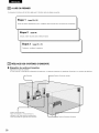
READ THIS FIRST
This AV Surround Receiver must be setup before use. Following these steps.
"_-o_ep
1
(page 8 to 15)
Choose the best location to setup the Speakers and connecting the components.
Step 2
(page 16)
Next, insert the batteries
Step 3
into the remote control unit.
(page
17 to 23)
Finally, setting up the system.
[]
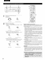
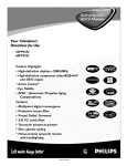
•
SETTING
UP THE SPEAKER
SYSTEMS
Speaker system layout
Basic system layout
• The following is an exampFe of the basic Eayout for a system consisting of six speaker systems
and a television
er speaker system
r
Front speaker systems
Set these at the sides of the TV or screen with
their front sur[aces as flush with the front of the
screen as possible
8
Surround
speaker systems
monitor:
[]
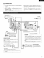
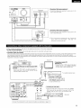
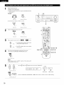
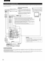
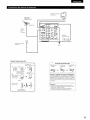
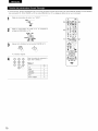
CONNECTIONS
• Do not plug in the power cord until all connections have been
completed.
• Be sure to connect the left and right channels properly (left with
left, right with right).
• Insert the plugs securely. Incomplete connections will result in
the generation of noise.
• Use the AC OUTLETS for audio equipment
only. Do not
use them for hair driers, etc.
• Note that binding pin plug cords together with power cords or
placing them near a power transformer will result in generating
hum or other noise.
• Noise or humming may be generated if a connected audio
equipment is used independently
without turning the power
of this unit on. If this happens, turn on the power of the this
unit.
Decoders with 6-channel
analog outputs, etc
-
EZ]
0
LINE
OUT
_z_
0
AC120V, 60HZ
©
''uJi
• .....
j
@-I
\
i
£
LINE IN
Connect the internal amplifier's
terminal {Refer to page 14)
subwoofer
I Connecting
Tape deck ot CD recorder
to the subwoofer
the AC OUTLETS_
AC OUTLETS
• SWITCHED
R
L
_PUT
(total capacity - 120 W (1 A)}
The power to these outlets is turned on and off in coniunction with
the POWER switch on the main unit, and when the power is
switched between on and standby from the remote control unit
No power is supplied from these outlets when this unit's power is at
standby Never connect equipment whose total capacity is above 120
W (1 A)
NOTE:
Only use the AC OUTLETS for audio equipment
Never use them for
hair driers, TVs or other electrical appliances
R
L
OUTI_UT
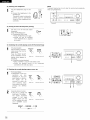
I Connecting
a tape
Connections
for
deck
]
recording:
Connect the tape deck's recording input jacks (LINE IN or
REC) to this unit's tape recording (OUT) iacks using pin plug
cords
Connections for playback:
Connect the tape deck's playback output iacks (LINE OUT or
PB) to this unit's tape playback fiN) jacks using pin plug cords
CO recordec MD recorder or other component
equipped with dJgJta_
output _acks
OPTICAL
E]oo
OU
R Pb'r
C
CD player
l- _
c_ o o
CZZZZZZZZ] _ _
[ Connecting
_
_
_
,
_
I DIGITAL
a CD player ]
connecttheCDp,y
output iacks (ANALOG OUTPUT) to
this unit's CD iacks using pin plug
cord
s
jacks ]
Use these for connections to audio equipment with diggal output
to Page 21 for instructions on setting this terminal
Refer
LINE
OUT
• Use 75 _)Johms cable pin cords (sold separately} for coaxial
connections
• Use optical cables (sold separately) for optical connections
9
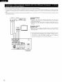
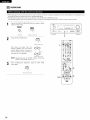
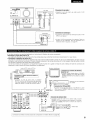
To connect the video signal, connect using a 75 £2/ohms video signal cable cord. Using an improper cable can result in a drop in sound quality.
TV or DBS tuner
•
out O_T_AL
__
I I
I Connecting
_ °
a TV/DBS
tuner
]
* Connect the TV's or DBS tuner's video output jack
(VIDEO OUTPUT) to the _
(yellow) TV/DBS iN
o
• Connect the TV's or DBS tuner's
(AUDIO OUTPUT) to the _
using pin plug cords
MONITOR OUT
• Connect the TV's video input iack {VIDEO
iNPUT) to the []_
MONITOR OUT
iack using a 75 _2!ohms video coaxial pin
plug cord
audio output iacks
TV/DBS iN jacks
I-
g
0
0
O
R
L
OUT
CC_×_L
A_o,o
v,oEo
°'G'l
¸_ I_
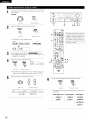
:o _c_=_ I DVD
player or VDP
I
UJ
!lJ
Monitor TV
I Connecting
I0
0
a DVD player or a video disc player
(VDP)
I
O
• Connect the DVD player's (video disc player's) video output jack (VIDEO OUTPUT) to
the _
{yellow) DVD/VDP iN iack using a 75 _/ohms video coaxial pin plug cord
• Connect the DVD player's {video disc player's) analog audio output jacks (ANALOG
AUDIO OUTPUT) to the _
DVD/VDP iN jacks using pin plug cords
• For better sound quality, we recommend using the DVD player with digital rather than
analog connections
DVD and VDP players can also be connected to the VCR terminals
I"1
0
0
ILl
1_1
J
@,_
NOTE:
Connection of the video disc Player Equipped with Dolby Digital RF
(AC-3RF) Output Jack
• Please use a commercially available adaptor when connecting the
Dolby Digital RF (AC-3RF) output iack of the video disc player to
the digital input jack
Please refer to the instruction manual of the adapter when making
connections
0
o
<
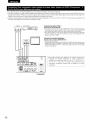
I Connecting
a video decks
VIDEO
IN
]
Video input/output
connections:
• Connect the video deck's video output jack {VIDEO OUT) to the _
(yellow) VCR OUT jack using 75 _/ohms video coaxial pin plug cords
Connecting the audio output jacks:
• Connect the video deck's audio output jacks (AUDIO OUT) to the _
iacks using pin plug cords
10
(yellow)
VCR IN iack, and the video deck's video input jack {VIDEO IN) to the
VCR IN iacks, and the video deck's audio input jacks {AUDIO IN} to the _
VCR OUT
r
m_m
[Connecting
I
Video game
a Video game
[ Connecting
Video camera
a Video camera equipment
• Connect the video camera equipment's
unit's V AUX INPUT iacks
[ ®®
--OUTP
®T
The V AUX terminal
VIDEO
equipment
• Connect tile Video ganle equipment's
unit's V AUX INPUT iacks
is covered
iacks to this
]
output
with a cap
cap m order to use the terminal
instructions on removing the cap}
OUT
]
output
{See
jacks to this
Remove this
page
4 for
• When marking connections, also refer to the operating instructions of the other components.
• A note on the S input jacks
The input selectors for the S inputs and pin jack inputs work in conjunction with each other.
• Precaution when using S-jacks
This unit's S-jacks (input and output) and video pin jacks (input and output) have independent circuit structures, so that video signals input from
the S-jacks are only output from the S-jack outputs and video signals input from the pin jacks are only output from the pin jack outputs.
When connecting this unit with equipment that is equipped with S-jacks, keep the above point in mind and make connections according to the
equipment's instruction manuals.
Monitor TV
DVD player, VDP, etc
[ Connecting a monitor TV]
MONITOR OUT
• Connect the TV's or DBS tuner's S video input
(S-VIDEO INPUT) to the _
MONITOR
OUT iack using a S jack connection cord
.......
o i£
0 _
LU_
_D
_
[ Connecting
DVD/VDP
a DVD player or video disc player (VDP) I
• Connect the DVD player's or video disc player's SVideo output jack to the S-VIDEO DVDNDP IN iack
using an S-Video connection cord
z_
_D_
TV or satellite broadcast tuner
° °°J
_H_H_H_H_H_H_H_H_
¢_
_
H_
_
VIDEO
* Connect
the TV's or
video outputjackIS-VIDEO
OUT
DBS
tuner's
S
OUTPUT)
to the _
TV/DBS IN iack using
an S jack connection cord
@@=
I Connecting
the video decks I
• Connect the video deck's S output jack IS-OUT) to the
VCR IN iack and the video deck's S input jack (SqN) to the
VCR OUT iack using S jack connection cords
%.., @-"
Video deck
VIDEO
Connect the components'
audio inputs and outputs
IN
_
as described on page 10. ]
11
• When making connections, also refer to the operating instructions of the other components.
• The signals input to the color difference (component) video jacks are not output from the VIDEO output jack (yellow) or the S-Video output jack.
)n addition, the video signals input to the VIDEO input (yellow) and S-Video input jacks are not output to the color difference (component) video
jacks.
• Some video sources with component video outputs are labeled h C8, CR, or Y, Pb, Pr, or Y, R-Y, B-Y. These terms all refer to component video
color difference output.
DVD player
[]
[]
Connecting
a DVD player
]
DVD IN jacks
• Connect the DVD player's coEor difference
(component)
video output
iacks
(COMPONENT VIDEO OUTPUT) to the COMPONENT
DVD IBI jack using 75 £dohms
coaxial video pin-plug cords
• In the same way, another video source with component video outputs such as a
TV/DBS tune_, etc, can be connected to the TV/DBS color difference (component)
video jacks
[]
Monitor
TV
Connecting
a monitor TV ]
MONITOR OUT jack
• Connect the TV's color difference
VIDEO INPUT) to the C©MPQNENT
video pin-plug cords¸
(component) video input iacks (COMPONENT
MQNETOR ©UT jack using 75 _Johms coaxiaE
The color difference input iacks may be indicated differently on some
TVs, monitors or video components ("CR, CB and Y", "R-Y, B-Y and Y',
"Pr, Pb and Y", etc.). For details, carefully read the operating
instructions included with the TV or other component.
(;]O B
12
rH m
DIRECTION OF
BROADCASTING
STATION
J
FM ANTENNA
@@_
@_
@@_
@@_
@,,.
•@ @,_@@l= D=-' @._
•.,@@, @@- _:_@_
.@ @.. @ _;=
75 _2/ohms
COAXIAL
CABLE
m
AM
OUTDOOR
ANTENNA
///_ /////
FM INDOOR
ANTENNA
GROUND
(An Accessory)
AM loop antenna assembly
Connection
antenna
and take out the
(_
c°r_necti°n
[_ne
a With the antenna
1 Push the
[ever
of AM
2
antennas
Insert the
conductor
3
Return
the
[ever
Bend in the reverse
direction
Note to CATV system
TIllS
ienTiTidel
attention
on top any stable
surface
]$
plov]ded
to Article
installer:
to
820 40
can
the
of the
CA_V
NEC
systeFN
which
_nsiaHerrs
provides
guidelines for proper grounding
and, Jn paldcu_ar, specifies
that the cable glound shal_ be connected to the grounding
system of tile build#lg, as close to the point of cable entry as
practical
Mount
b With the antenna
attached to a
wal_
Installation
terminals
hole
Notes:
• DO not connect two FM antennas slrnultaneously
• Even if an external AM antenna is used do not disconnect
the AM loop antenna
• Make sure AM loop antenna lead termJrla_s do not touch
metal parts of the panel
13
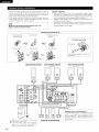
• Connect the speaker terminals with the speakers making sure that like
polarities are matched ((_ with (_, _ with 8) Mismatching of polarities will
result in weak central sound, unclear orientation of the various instruments,
and the sense of direction of the stereo being impaired
• When making connections, take care that none of the individual conductors
of the speaker cord come in contact with adjacent terminals, with other
speaker cord conductors, or with the rear panel
NOTE:
NEVER touch the speaker terminals when the power is on,
Doing so could result in electric shocks.
Connecting
2 Insert the cord
Loosen by turning
counterclockwise
Speaker
Impedance
• When speaker systems A and B are use separately, speakers with an
_mpedance of 6 to 16 _dohms can be connected for use as front speakers
• Be careful when using two paks of front speakers (A + B) at the same time,
since use of speakers with an impedance of 12 to I6 _/ohms
• Speakers with an impedance of 6 to I6 _/ohms can be connected for use
as center and surround speakers
• The protector circuit may be activated if the set is played for long periods of
time at high volumes when speakers with an impedance lower than the
specified impedance are connected
the speaker cords
3 Tighten by turning
clockwise
Connecting banana plugs
=4>
Push the lever
=4>
2 Inser[ the cord
bananaplug
\
3 Return the lever
Turn clockwise
banana plug
I CENTER SPEAKER SYSTEM
I
FRONT SPEAKER SYSTEMS 1
System A
D
IFRONT
to tighten,
then insert the
SPEAKER SYSTEMS
]
System B
4-
--
_#n_ @
_Y_ I
@@=@_
@@, @(
@@,@(
i
the speaker away to a position
have this effect
Connection
iack for subwoofer
with built-in
amplifier
(super woofer),
etc
To achieve
Dolby Digital
(AC-3) playback
effect,
use a unit that can sufficiently
reproduce
frequencies
of under 80 Hz
14
SURROUND
SPEAKER SYSTEMS
I
where
it does not
,, This unit is equipped with a high-speed protection circuit. The purpose of this circuit is to protect the speakers under
circumstances such as when the output of the power amplifier is inadvertently short-circuited and a large current flows,
when the temperature surrounding the unit becomes unusually high, or when the unit is used at high output over a long
period which results in an extreme temperature rise.
When the protection circuit is activated, the speaker output is cut off and the power supply indicator LED flashes. Should
this occur, please follow these steps: be sure to switch off the power of this unit, check whether there are any faults with
the wiring of the speaker cables or input cables, and wait for the unit to cool down if it is very hot. Improve the ventilation
condition around the unit and switch the power back on.
If the protection circuit is activated again even though there are no problems with the wiring or the ventilation around the
unit, switch off the power and contact a DENON service center.
•
The protector circuit may be activated if the set is played for long periods of time at high volumes when speakers with
an impedance lower than the specified impedance (for example speakers with an impedance of lower than 4 _/ohms)
are connected. If the protector circuit is activated, the speaker output is cut off. Turn off the set's power, wait for the set
to cool down, improve the ventilation around the set, then turn the power back on.
15
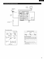
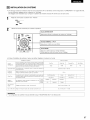
[]
USING
THE REMOTE
CONTROL
UNIT
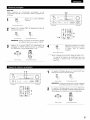
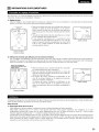
Following the procedure outlined below, insert the batteries before using the remote control unit.
Point the remote control unit at the remote
control sensor as shown
on the diagram at the left.
NOTES:
• The remote control unit can be used from a straight distance of
approximately 23 feet/7 meters, but this distance will shorten or
operation will become difficult if there are obstacles between the
remote control unit and the remote control sensor, if the remote
control sensor is exposed to direct sunlight or other strong light, or
if operated from an angle.
• Neon signs or other devices emitting pulse-type noise nearby may
result in malfunction, so keep the set as far away from such
devices as possible.
30°
Appro_
(_) Press as shown by the arrow and slide
off.
_
Insert the R6P/AA batteries
shown on the diagram.
properly, as
(_) Close the lid.
NOTES:
• Use only R6P/AA batteries for replacement.
• Be sure the polarities are correct. (See the illustration inside the battery compartment.)
• Remove the batteries if the remote control transmitter will not be used for an extended
period of time.
• If batteries leak, dispose of them immediately. Avoid touching the leaked material or letting it come in contact with clothing, etc. Clean the
battery compartment thoroughly before installing new batteries.
• Have replacement batteries on hand so that the old batteries can be replaced as quickly as possible when the time comes.
• Even if less than a year has passed, replace the batteries with new ones if the set does not operate even when the remote control unit is
operated nearby the set. {The included battery is only for verifying operation. Replace it with a new battery as soon as possible.)
16
[]
SETTING
UP THE SYSTEM
• Once aft connections
with other AV components
have been completed
various settings described below on the display.
These settings are required to set up the listening
1
room's
AV system
as described
centered
in "CONNECTIONS"
(see pages 9 to 15), make the
around the this unit.
Set the slide switch to "AUDIO".
AUDIO=_
• VIDEO--
2
Use the following
buttons to set up the system:
SYSTEM
I
SETUP button
Press this to display the system setup on the display
CURSOR buttons
(A, V, _1, I_)
Press this change what appears on the display
ENTER button
Press this to switch tile display
Also use this button to complete
the setting
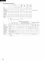
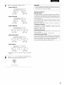
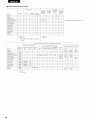
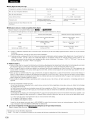
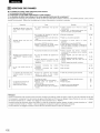
• System setup items and default values (set upon shipment from the factory)
System
Speaker
Configuration
Subwoofet
setup
Default
Input the combination
of speakers
in your system
and their
corresponding
s_zes (SMALL for regular speakers, LARGE for full size
full range) to automatically
set the composition
ot the slgr_als output
from the speakers and the frequency response¸
Mode
This selects
signals
the
subwoofer
speaker
playing
deep
the bass sound
the subwoofet
Set the frequency
(Hz) below
various speakers
is to be output
De_ay Time
This parameter
is for optimizing
the timing with which the audio
signals are produced from the speakers ar}d subwooter aecordJrlg to
This assigns
Auto
Ext
Set the
_nSW Level
input
Ext
function
In Subwoofer
Front & Subwoofer
COAXIAL
CD
level
NOTE:
• The system setup is not displayed when "HEADPHONE
Small
mode
Sub Woofer
Yes
= Normal
Center
OPTICAL
Surround
12ft{36ml
1
OPTICAL
DVD/VDP
L & R
/0ft(30m)
2
TV/DBS
Auto
p_ayback
Sp
80 Hz
setting
channel
Surround
Inputs
_npt
mode
Small
/2 ft (36m)
the digita_ input jacks for the different
surround
Large
Subwoofer
posltion
sources
Auto Surround
Mode
Center Sp
of the
Diat_l
Digltal In
Asslgnment
Front Sp
bass
Crossover
Frequency
the listening
which
from
for
settlrlgs
Ext
Sulround
Mode
= ON
In SW Leve_ = +1_ dB
ONLY" is selected.
17
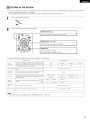
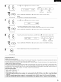
1
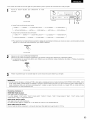
Check that all the components are correct, then press the POWER operation switch on the main unit or
the POWER button on the remote control unit to turn on the power.
(Main unit)
sETup
{Remote control
unit)
Press the SYSTEM SETUP button to enter the setting.
:+::iii;'.,.':iii;T
EN :iii;
ET UF::']
NOTE: Please make sure the "AUDIO"
Press the ENTER or _
position of the slide switch on the remote control unit.
(down) button to switch to the speaker configuration
set up.
NOTE:
Press the SYSTEM SETUP button again to finish system set up. System set up can be finished at any time.
made up to that point are entered.
1
The changes to the settings
t&
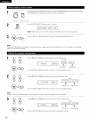
Use the
_ (left) and _
(right) buttons to select your front speaker type.
(initial)
:i. F::R0 i".iT
L F::i
RGii
_
(left) button
(right) button
Press the ENTER or _
(down) button to switch to the center speaker setting.
Use the
(right) buttons to select your center speaker type.
_ (left) and _
{initial)
(left) button
Press the ENTER or _
(right) button
(down) button to switch to the surround speaker setting.
NOTE:
• When "Small"
has been selected for the front speakers,
Use the
"Large"
_ (left) and _
cannot be selected for the center speaker.
(right) buttons to select your surround speaker type.
(initial)
[3
=.iii;i...iF;i=.F;i=.==
=:::[bii:::iii
]
___
(left) button
Press the ENTER or <:_
18
(down) button to switch to the subwoofer
setting.
(right) button
NOTE:
• When "Small"
4
has been selected for the front speakers,
"Large"
cannot be selected for the surround speakers.
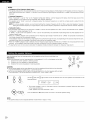
t&
Use the
_ (left) and _
(right) buttons to select your subwoofer
setting.
(Initial)
[ =::J" :iii: ==J...J
0 0 F:"Ei[J:i;:
"? E :iii:]
(left) button
Press the ENTER or _
setting.
(down) button to enter the settings and switch
(right} button
to the SUBWOOFER
MODE
• Parameters
Large ......
Select this when using speakers that can fully reproduce low sounds of below 80 Hz.
Small ......
Select this when using speakers that cannot reproduce low sounds of below 80 Hz with sufficient
selected, low frequencies of below 80 Hz are assigned to the subwoofer.
Select this when no speakers are installed.
Select "Yes" when a subwoofer is installed, "No" when it's not installed.
None ......
Yes/No....
volume. When this setting
is
NOTE:
Select "Large" or "Small" not according to the physical size of the speaker, but according to the bass reproduction capacity at 80 Hz. if you cannot
determine the best setting, try comparing the sound when set to "Small" and when set to "Large", at a level that will not damage the speakers.
Caution:
In case the subwoofer is not used, be sure to set "Subwoofer
not reproduced in some mode.
1
= No", or the bass sound of front channel is divided to subwoofer
t_
Use the
_ (left) and _
(right) buttons to select the Subwoofer
mode.
(Initial)
(left) button
2
channel and
(right) button
Press the ENTER or _
(down) button to enter the setting and switch to the Crossover
Use the
(right) buttons to select the Crossover Frequency.
_ (left) and _
Frequency setting.
(Initial)
[6cR==ouER
s,?,H:z:]
(left) button
Press the ENTER or _:_
(right) button
(down) button to enter the setting and switch to the SPEAKER DISTANCE setting.
19
NOTES:
-- Assignment of low frequency signal range -• The signals produced from the subwoofer channel are LFE signals (during playback of Dolby Digital or DTS signals) and the low frequency
signal range of channels set to "SMALL" in the setup. The low frequency signal range of channels set to "LARGE" are produced from those
channels.
-- Crossover Frequency -• When "Subwoofer"
is set to "Yes" at the "Speaker Configuration Setting", set the frequency (Hz) below which the bass sound of the
various speakers is to be output from the subwoofer (the crossover frequency).
• For speakers set to "Small", sound with a frequency below the crossover frequency is cut, and the cut bass sound is output from the
subwoofer instead.
NOTE:For ordinary speaker systems, we recommend setting the crossover frequency to 80 Hz. When using small speakers, however,
setting the crossover frequency to a high frequency may improve frequency response for frequencies near the crossover frequency.
-- Subwoofer
mode-
• The subwoofer mode setting is only valid when "LARGE" is set for the front speakers and "YES" is set for the subwoofer in the "Speaker
Configuration" settings (see pages 18, 19).
If "SMALL" is set for the front speakers or "NO" is set for the subwoofer, the subwoofer mode setting does not affect playback of low
frequency signal range.
• When the "+MAIN" playback mode is selected, the low frequency signal range of channels set to "LARGE" are produced simultaneously
from those channels and the subwoofer channel.
In this playback mode, the low frequency range expand more uniformly through the room, but depending on the size and shape of the room,
interference may result in a decrease of the actual volume of the low frequency range.
• When the "NORM" playback mode is selected, the low frequency signal range of channels set to "LARGE" are only produced from those
channels. In this playback mode there tends to be little interference of the low frequency range in the room.
• Try playing the music or movie source and select the playback mode providing the stronger low frequency range sound.
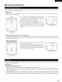
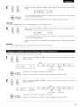
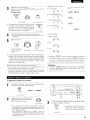
Input the distances from the listening position to the speakers and set the surround delay time.
Preparations:
Measure the distances
L1: Distance from
L2: Distance from
LS: Distance from
from the listening position to the speakers (L1 to L3 on the diagram at the right).
center speaker to listening position
front speakers to listening position
surround speakers to listening position
CAUTION:
Set the center speaker at the same distance from the front speakers (left and right) or the subwoofer,
or so that the difference in distance (L2 - L1) is 5 feet or less.
Set the surround speakers (left and right) at the same distance from the front speakers (left and right)
or the subwoofer, or so that the difference in distance (L2 - L3) is 15 feet or less.
1
FL
Use the
_
Center
FR
Listening
/position
Sk
SR
(left) and _ (right) buttons to set the distance from the front speakers and subwoofer
to the
listening position.
;::= i:::":i;i:iii..":iii;i
..
_i
"" ""
.=.=
.=...."
.=.==..
• The number changes in units of 1 foot each time one of the buttons is pressed. Select the value closest
to the measured distance.
("/SW" appears only when subwoofer = yes.)
Press the ENTER or _
(down) button to switch to the center speaker setting.
NOTE:
• The speaker distance can be adjusted between
2O
0 and 60 feet in steps of 1 foot.
2
Use the _
{left) and _) (right) buttons to set the distance from the center speaker to the listening position.
:iii: =....,....,""
E:"_...,m",
,....,...E:"
_:::=
i 2 "i:""i.
• The number changes in units of 1 foot each time one of the buttons is pressed. Select the value closest
to the measured distance.
Press the ENTER or _
(down) button to switch to the surround speakers setting.
NOTE:
• No setting when "None"
has been selected for the center speaker.
P,
Use the
position.
_
(left) and _
{right) buttons
=iiiE:iii;UJ:;;:J:;;:
==
to set the distance from the surround
speakers to the listening
i E:::E
.E:i
• The number changes in units of 1 foot each time one of the buttons is pressed. Select the value closest
to the measured distance.
Press the ENTER or _
{down) button to enter the setting and switch the DIGITAL input {COAX) setting.
NOTE:
• No setting when "None"
Input the type of components
1
has been selected for the surround
speakers.
connected to the digital input terminals.
J%
P,
terminal.
(_
('\\
Use the _
(left) and _ {right) buttons to assign the input function connected to the COAXIAL input {COAXIAL)
(Initial)
I1,', II,,cRII,::::,:::R
i ili!i i::::i:::ii:::i::.:: CD
{left) button
{right) button
Press the ENTER or _
{down) button to switch the optical input 1 (OPT1) setting.
° Select "OFF" if nothing is connected.
__
2
(OPTICAL 1) terminal.
(_
&/\\
Use the
_
(left) and
_
(right) buttons
to assign the input function
connected
to the OPTICAL input 1
(Initial}
:i.:i. 0 F::'
T :i.
,...,-,,,""'...
,..."
....
{left) button
__
(right) button
Press the ENTER or _z_ {down) button to switch the optical input 2 (OPT2) setting.
° Select "OFF" if nothing is connected.
21
(OPTICAL 2) terminal.
(_
&/\\
Use the
_
(left} and
_
(right) buttons
to assign the input function
connected
to the OPTICAL input 2
(Initial)
i :2 0F'T:?
I1,', II,,,:::R
IIc,:: ,R
TU
(left} button
Press the ENTER or _
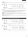
(down} button to switch the auto surround
• Select "OFF" if nothing is connected.
__
{right) button
mode setting.
NOTE:
• TUNER, V. AUX cannot be selected.
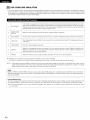
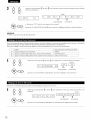
Per the three kinds of input signals as shown below, the surround mode played the last is stored in the memory. At next time it the same signal
inputs, the memorized surround mode is automatically selected and the signal is played.
Note that the surround mode setting is also stored separately for the different input function.
1
SIGNAL
Default Auto Surround Mode
_.}
Analog and PCM 2-channel signals
STEREO
(2}
2-channel signals of Dolby Digital, DTS or other multichannel
(3}
Multichannel
format
signals of Dolby Digital, DTS or other multichannel
Use the
_ (left) and _
format
Dolby PLI| Cinema
Dolby or DTS Surround
(right) buttons to select the Auto Surround mode.
(Initial)
[:,.3
,:::,m:::o,RR..
o,,]
(left} button
Press the ENTER or _
Set the method of playback of the analog input signal connected
1
Use the
_ (left} and _
(right) button
(down} button to switch the Ext. In SW Level setting.
to the Ext. In terminal.
(right) buttons to select the Ext. In Subwoofer
channel Level playback.
(initial}
1
:i.4 E:::.:',i
,, :[i..i :E;i.,.i + :i.!:5/
__
(left) button
Press the ENTER or _
22
_
(right) button
(down} button if you want to start the settings over from the beginning.
_--_
Press the SYSTEM SETUP button to finish system set up.
This completes the system setup operations. Once the system is set up, there is no need to make the settings again unless other components
or speakers are connected to or the speaker layout is changed.
23
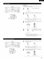
[]
REMOTE
CONTROL
UNIT
• Turn on the power of the different components
1
Set mode switch
before operating them.
1 to "AUDIO".
/IUDIO•
_D
o_l[IEO m
3
set
mode (CD,
switchCDR/MD
2 to theor position
for the component
operated.
Tape deck)
to be
CD_"D_
_
2
1
W
Operate the audio component.
• For details, refer to the component's operating instructions.
"_ While this remote control is compatible with a wide range of infrared controlled
be operated with this remote control.
1.CD player (CD) and CD recorder
(CDR/MD) system buttons
441, I_1_
•
I_
1414, _
II
DISC
SKIP+
and
MD
recorder
I_1_
: Stop
: Play
•
I_
: Auto search (cue)
: Pause
: Switch discs
(for CD changers
components,
2.Tape deck (TAPE)system
: Manual search (forward and reverse)
_1
A/B
m
some models of components
buttons
: Rewind
: Fast-torward
: Stop
: Forward play
: Reverse play
: Switch between
decks A and B
only)
3. Tuner system buttons
SHIFT
CHANNEL
+, -
@®®
®®@
24
up/down
TUNING
+, BAND
MODE
: Frequency
up/down
: Switch between
: Switch between
MEMORY
: Preset memory
NOTE:
• TUNER can be operated when the switch is at "AUDIO"
: Switch preset channel lange
: Preset channel
position.
the AM and FM bands
auto and mono
may not
DENON and other makes of components can be operated by setting the preset memory.
This remote control unit can be used to operate components of other manufacturers without
manufacturer of the component as shown on the List of Preset Codes {pages 104-10B).
Operation is not possible for some models.
1
Set mode switch
1 to "AUDIO"
using the learning function
the
or "VIDEO".
3
AUDIO•
o_(_)o
•VIDE0--
E
Set the AUDIO side for the CD, Tape deck or CDR/MD
position, to the VIDEO side for the DVD/VDP, DBS/CABLE,
VCR or TV position.
2
by registering
Set mode switch 2 to the component
CDR/MD
co-,_ r
m
I
_B
4
to be registered.
_PE
2
DVD/VDP_ _ _ *--_/
'_qlR MIB$/g_lN
Press the ON/SOURCE
same time.
button
and the OFF button
at the
• Indicator flash.
4
(_
(_)
@
(_)
@
@
(_
@(Q)_(_
B[NON
Referring to the included List of
Preset Codes, use the number
buttons to input the preset code (a
3-digit
number}
for
the
whose signals you want to store in
manufacturer
of the component
the
memory.
To store the codes of another
repeat steps 1 to 4.
component
in the memory,
NOTES:
• The signals for the pressed buttons are emitted while setting the preset memory. To avoid accidental operation, cover the remote control
unit's transmitting window while setting the preset memory.
• Depending on the model and year of manufacture, this function cannot be used for some models, even if they are of makes listed on the
included list of preset codes.
• Some manufacturers use more than one type of remote control code. Refer to the included list of preset codes to change the number and
check.
• The preset memory
can be set for one component
only among the following: CDR/MD,
DVD/VDP
and DBS/CABLE.
The preset codes are as follows upon shipment from the factory and after resetting:
TV, VCR .....................................................
HITACHI
CD, TAPE ..................................................
DENON
CDR/MD ...................................................
DENON {CDR)
DVD/VDP ..................................................
DENON {DVD)
DBS/CABLE ..............................................
ABC {CABLE}
25
Set mode switch
I
1 to "AUDIO"
or "VIDEO".
_IBIO•
•_BEO--
__,_L
Set
the
AUDIO
side
to the
VIDEO
position,
for
the
side
CD,
tape
for the
deck
DVD/VDP,
or
CDR/MD
DBS/CABLE,
3
VCR or TV position.
2
Set mode switch 2 to the component
you want to operate.
1
D'_'D/VDP
-_)
",--_,f
,,:R]'_Bsl_=
3
DEi_
Operate the component.
• For details, refer to the component'a operating instructions.
-_ Some models cannot be operated with this remote control unit.
1. Digital
DVD
video
disc player
SETUP)
system
(DVD,
2. Video
buttons
system
POWER
: Power on/standby
(ON/SOURCEI
41_1,_-I_
•
I_
14141,1_i
II
0~
9, +10:
skip +
DISPLAY
MENU
RETURN
SETUP
E
: Manual search
(forward and reverse)
i
t
_i
disc player
(VDP)
buttons
POWER
: Power on/standby
(ON/SOU RCEI
41_1,_-I_
: Manual search
E
_
i
_m
(forward and reverse)
: Stop
: Play
: Auto search
(to beginning of tlack)
: Pause
®®
•
I_
14141,_
®®
0~9, +I0
II
: Stop
: Play
: Auto search (cue)
: Pause
: 10key
®®®
@SN
@®@
10key
: Disc skip
(for DVD changer only)
{c_
_:3D
: Switch display
: Menu
: Return
: Setup
P,, V <l, b* : Cursor up, down, left
and right
ENTER
NOTE:
• Some
: Enter setting
manufacturers
use
different
names for the DVD
remote control buttons, so also
refer to the instructions
on
remote
control
for
that
component.
26
I_NON
DENON
3. Video deck (VCR) system
buttons
4. Digital
(DBS)
(CABLE)
POWER
: Power on/standby
(ON/SOURCE)
<1_1,1_
: Stop
II
: Play
: Pause
Channel +, -
and
system
satellite
cable
buttons
POWER
: Power on/standby
(ON/SOU RCEI
: Manual search
(forward and reverse)
•
broadcast
tuner
MENU
RETURN
®@
/_, _:', <, _
ENTER
CHANNEL
: Channels
®@
: Menu
: Return
: Cursor up, down, left
and right
: Enter
: Switch channels
0~9, +10
: Channels
DISPLAY
VQL +, -
: Switch display
: Volume up/down
DENON
Ro4_o
DENON
j
5. Monitor
buttons
TV (TV) system
POWER
: Power on/standby
(ON/SOURCE)
MENU
RETURN
%, _:', <, _
ENTER
CHANNEL
: Menu
: Return
: Cursor up, down, left
and right
Enter
Switch channels
®®®
®®
0~9, +10
DISPLAY
_NCR
VOL
+,-
Channels
Switch display
Switch between
TV
and video player
Volume up/down
DENON
J
NOTES:
• For this CD, CDR, MD and TAPE components, buttons can be operated in the same way as for Denon audio components
• The TV can be operated when the switch is at DVD/VDP, VCR, TV position.
(page 24).
27
• "Punch Through" is a function allowing
CDR/MD, DVD/VDP or VCR components
1
Set mode switch
you to operate the PLAY, STOP, MANUAL SEARCH and AUTO SEARCH buttons
when in the DBS/CABLE or TV mode. By default, nothing is set.
1 to "VIDEO".
3
3
o'_IBE0 m
E
Set
mode switch
(DBS/CABLE
or TV). 2 to the
component
to be registered
m
I
_B
4
cD_d_D
1_E
VCR
L_BSICABLE
1
Press the DVD/VDP power button and the TV power button at
the same time.
BIro[_Op
p/
• Indicator flash.
4
®®©
®®®
®®®
input the number of the
component you want to set. (See
Table 1)
Table 1
No.
CD
28
1
TAPE
2
CDR/MD
3
DVD/VDP
4
VCR
5
No setting
0
2
on the CD, TAPE,
[]
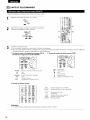
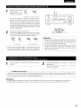
OPERATION
,
ooo
ZO °
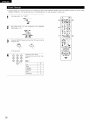
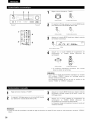
1
Preparations:
Check that all connections
1
are proper.
Turn on the power.
Press the ON/STANDBY
button
on the main unit or
ON/SOURCE button on the remote control unit to turn on the
power.
8N/ST_D_t
1
2
_--1
{Main unit)
®®@0
{Remote control
unit)
• ON/STANDBY
When the button is pressed, the power turns on and the
display lights after approximately 1 second.
When pressed again, the power turns off, the standby
mode is set and the display turns off.
Several seconds are required from the time the power
operation switch is set to the "ON" position until sound is
output. This is due to the built-in muting circuit that
prevents noise when the power switch is turned on and off.
Select the front speakers.
Press the SPEAKER A or B button to turn the speaker on.
®00--_
Xa_Ft
S
{Main unit)
w
8FE_R
{Remote
control
u_it}
• The front speaker A, B setting can be also be changed
the SPEAKER button on the remote control unit.
with
DENON
29
1
2
o
5
.
@
3
1
[
ooo
_
[
C _D
_
3
1
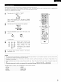
Select the input source to be played.
Example: CD
CD
h,_rr ELr_11=_
0
(Main unit}
(Remote
control unit)
Select
the input
mode. mode
• Selecting
the analog
Press the ANALOG button to switch to the analog input.
A_LOG
(Mainunit)
(Remotecontrolunit)
• Selecting the external input (EXT. IN) mode
Press the EXT. IN (or the EX_. IN button on the remote
control unit) to switch the external input.
EXT. IN
(Mainunit)
(Remotecontrolunit)
• Selecting the AUTO, PCM and DTS modes
The mode switches as shown below each time the INPUT
MODE button is pressed.
AUTO_
PCM
_
DTS
In this mode, the types of signals being input to the digital and
analog input jacks for the selected input source are detected and
the program in the this unit's surround decoder is selected
automatically upon playback. This mode can be selected for all
input sources other than TUNER.
The presence or absence of digital signals is detected, the signals
input to the digital input jacks are identified and decoding and
playback are performed automatically in DTS, Dolby Digital or
PCM (2 channel stereo) format. If no digital signal is being input,
the analog input jacks are selected.
Use this mode to play Dolby Digital signals.
(2} PCM (exclusive PCM signal playback mode)
Decoding and playback are only performed when PCM signals are
being input.
Note that noise may be generated when using this mode to play
signals other than PCM signals.
@} DTS {exclusive DTS signal playback mode)
Decoding and playback are only performed when DTS signals are
being input.
(4} ANALOG (exclusive analog audio signal playback mode)
The signals input to the analog input jacks are decoded
played.
_5} EX_. IN (external decoder input jack selection mode)
INPUT MOOE
(Main unit)
Input mode selection function
Different input modes can be selected for the different input sources.
The selected input modes for the separate input sources are stored
in the memory.
_} AUTO (All auto mode)
(Remote
control unit)
and
The signals being input to the external decoder input jacks are
played without passing through the surround circuitry.
NOTE:
• Note that noise will be output when CDs or LDs recorded in DTS
format are played in the "PCM" (exclusive PCM signal playback) or
"ANALOG" (exclusive analog audio signal playback) mode. Select
the AUTO or DTS (exclusive DTS signal playback) mode when
playing signals recorded in DTS from a laser disc player.
Notes on playing a source encoded with DTS
I
• Noise may be generated at the beginning of playback and I
while searching during DTS playback in the AUTO mode. If
so, play in the DTS mode.
• In some rare cases the noise may be generated when you
preform the operat on to stop p ayback of a DTS-CD or DTS-LD.
3O
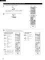
Select the play mode.
Press the SURROUND
knob.
MODE button, then turn the SELECT
Input mode display
• in the AUTO mode
One
Pc_
I_Pbr
©
Example: Stereo
8URROUNDMODE
of these
Hghts, depending
on the
inputsignal
_
• in the DIGITAL PCM mode
S_R_
_pLr_
AUTO
O
_
®\
_1
• in the DIGITAL DTS mode
(Main unit}
(Remote
To select the surround mode while adjusting
the surround parameters, channel volume or
tone control,
press the surround
button then operate the selector.
control unit)
SURROUND MOOE
AUTO
_pLr_
PC_
o
o
• in the ANALOG mode
mode
_pLr_
PC_
AUTO
(See page 34.)
{Mainunit)
Input signal display
Start
selected component.
• Forplayback
operatingon the
instructions,
refer to the
manual.
component's
• DOLBY DIGITAL
Adjust the volume.
o
MAS_R '40LUME
• DTS
OIG_TAL
©
The volume
displayed on the
master volume level
{Main unit)
(Remote
contro_
unit)
D_GITAL
O
display
'_ The volume can be adjusted within the range of -70 to 0 to 18 dB,
in steps of 1 dB. However, when the channel level is set as
described on page 34, if the volume for any channel is set at +1 dB
or greater, the volume cannot be adjusted up to 18 dB. (In this case
the maximum volume is adjusted to "18 dB -- (Maximum value of
channel level)".)
CDs or LDs are played in the
When playing DTS-compatible sources, be sure to connect the
source component to the digital input jacks (OPTICAL/COAXIAL}
and set the input mode to "DTS".
[1] Adjusting the sound quality
The _
O
indicator lights when digital signals are being input
properly. If the _
indicator does not light, check whether
the digital input component
correct and whether
setup {page 21) and connections
the component's
are
power is turned on.
NOTE:
Input mode when playing DTS sources
• Noise will be output if DTS compatible
"ANALOG" or "PCM" mode.
The
toneis switches
button
pressed.
C
• PCM
level is
• The _
containing
heard.
indicator will light when playing CD-ROMs
data other than audio signals, but no sound will be
(tone)
as follows each time the TONE CONTROL
©
TONE
CON'PROL
BASS _
o
o
o
TREBLE
O
@
o
o
(Main unit)
3
With
the selected,
name of the
to be
adjusted
turn volume
the SELECT
knob to adjust the level.
O
21
s_,T
If you do not want the bass and treble to be adjusted, turn on
the tone defeat mode.
(Main unit)
TONE DEFEAT
• To increase the bass or treble: Turn the control clockwise.
(The bass or treble sound can be increased to up to +12 dB
in steps of 2 dB.)
• To decrease
the bass or treble:
Turn the control
counterclockwise.
{The bass or treble sound can be
decreased to up to -12 dB in steps of 2 dB.}
,_ The signals do not pass through the
bass and treble adjustment circuits,
so it provides higher quality sound.
(Main unit)
31
NOTE:
[2] Listening over headphones
Plug the headphones'
jack.
plug into the
-_ Connect the headphones
PHONES jack.
To prevent hearing loss, do not raise the volume
when using headphones.
PHONES
to the
z
Oo
The pre-out output (including the
speaker output) is automatically
turned off when headphones are
connected.
[3] Turning the sound off temporarily
1
level excessively
o
o
o
Od_o
!
o
_
ooo
_
!
oo
_
o©o
o
o
(muting)
_1
Use this to turn off the audio output
temporarily.
Press the MUTING button.
®
_o o
-_ Cancelling MUTING mode.
• Press the MUTING button again.
• Muting
will also be cancelled
when MASTER VOL is adjusted
up or down.
/
[4] Combining the currently playing sound with the desired image
1
Simulcast playback
Use this switch to monitor a
_DEO_LECT
VtDEOS_'r
video source other than the
audio source.
Press the VIDEO SELECT
button repeatedly until the
desired source appears on
(Mai[iunit)
{Remotecontrolunit}
ooo t_
the display.
Cancelling simulcast playback.
• Select "SOURCE" using the video select button.
• Switch
the program
source
to
connected to the video input jacks.
the
o°0o
°
1
component
[5] Checking the currently playing program source, etc.
1
Front panel display
• Descriptions of the unit's
operations
are
also
displayed
on the front
panel display. In addition,
the
display
can
be
switched
to check the
_^_
unit's
operating
status
while playing a source by
pressing
the
STATUS
button.
2
;;0
oo-_==oi
(Maillunit)
{Remote
(bdght, medium, dim and
off) by pressing the main
unit's
DIMMER
button
DIMMER
DIMM_
--.
(Maillunit)
{Remote
repeatedly.
_
MEDIUM
OFF -_
32
_r_it}
2
Using the dimmer function
• Use this to change the
brightness of the display.
The
display
brightness
changes
in four
steps
BRIGHT
control
_
DIM
control
ur_it}
1
1
Set the external input (EXT.
IN) mode.
Press the EXT. iN to switch
EXT, IN
2
the external input.
(Mainunit)
(Remotecontrolunit}
Once this is selected, the input signals connected to the FL
(front left), FR (front right), C (center), SL (surround left), and
SR (surround right) channels of the EX_. IN jacks are output
directly to the front (left and right), center, surround (left and
right) speaker systems without passing through the surround
circuitry.
in addition, the signal input to the SW (subwoofer) jack is
output to the PRE OUT SUBWOOFER jack.
2
1
f E
--o
z:
o o
L_d
o
o_o
@
L_d
Cancelling the external input mode
To cancel the external input (EXT. IN) setting, press the INPUT
MODE (AUTO, PCM, DTS) or ANALOG button to switch to
the desired input mode. (See page 30.)
INI_/T
MODE
NOTES:
ANALOO
(Main unit}
(Remote control unit}
• When the input mode is set to the external input (EXT. IN), the play
mode (DIRECT, STEREO, DOLBY/DTS SURROUND, 5CH STEREO
or DSP SIMULATION) cannot be selected.
Follow step f to 3 under "Playing the input source".
Simultaneous
• In play modes other than the external input mode, the signals
connected to EXT. IN jacks cannot be played. In addition, signals
cannot be output from channels not connected to the input
jacks.
• The external input mode can be set for any input source. To
watch video while listening to sound, select the input source to
which the video signal is connected, then set this mode.
Start recording on the tape or video deck.
For instructions,
refer to the component's
instructions.
operating
recording
The signals of the source selected with the function selector button are output simultaneously to the CDR/TAPE and VCR REC OUT jacks. If
a total of two tape and/or video decks are connected and set to the recording mode, the same source can be recorded simultaneously on
every decks.
NOTES:
• The AUDIO iN's signal selected with the function selector button are output to the CDR/TAPE and VCR AUDIO OUT jacks.
• The DIGITAL IN's signal selected with the function selector button are output to the DIGITAL OUT (OPTICAL) jack.
33
F_SURROUND
• Before playing with the surround function, be sure to use the test tones to adjust the playback level from each speakers. This adjustment
be performed from the remote control unit, as {described) below.
• The adjustment with the test tones is only effective in the DOLBY/DTS SURROUND modes.
The adjusted playback levels for the different surround modes are automatically stored in the memory of each surround modes.
Set the orDOLBY/DTS
Digital
DTS) modes.SURROUND (Dolby Pro Logic [ior Dolby
DOLBY/_T8
O
(Main unit}
@
o
o
o
O
_
o
ooo
660
(Remote control unit}
1
2
Press
the TEST TONE
button.
_STTONE
{Remote
cor_trol
unit}
1
Test tones
are output
from
the
different speakers. Use the channel
volume adjust buttons to adjust so
that the volume of the test tones is
the same for all the speakers.
(Remote colltrol unit)
NOTE:
Please
make
switch
on the
After completing
button again.
the
sure
the
remote
"AUDIO"
control
adjustment,
position
of the
slide
unit.
press the TEST
TONE
_ST_NE
2
{Remote
c0ntlol
unit}
2,3
2
w
DENON
34
o
can
I
• After adjusting using the test tone._ adjust the channel levels either according to the playback sources or to suit your tastes, as (described)
below.
1
Select the speaker whose level you want to adjust.
o
@
(Main unit}
The channel switches
is pressed.
(Remote control
o
_o
unit)
as shown below each time the button
2
Adjust the level of the selected speaker.
I
Fs .
2
NOTE: Please make sure the "AUDIO" position of the slide
switch on the remote control unit.
2
o
1
2
(Main unit}
Only adjustable when the
channel is selected with the
CH VOL buttons on the main
unit.
(Remote
contlo_
unit}
Default setting of channel level is 0 dB.
-_ The level of the selected speaker can be adjusted within
the range of +12 to -12 dB using the SELECT knob or
cursor buttons.
SW channel level can be turned off by decreasing one step
from 12 dB.
OFF e_-12 dB ee 12 dB
35
1
Select the function to which the component
is connected.
you want to play
Example:
{Ma_n unit)
2
{Remote
co[itrol
©
o.::
C o
88o
o
[
oo
o
_:_
_im:_
o
o
o
unit)
Select the Dolby Surround Pro Logic [1 mode.
BCI_I
BT8
SURROUND
_
The Dolby Surround Pro Logic [1
Cinema or Music mode can be
2
{Main unit}
chosen directly by pressing the
CINEMA or MUSIC button on
{Remote control unit}
• The Dolby Pro Logic indicator lights.
Display
[pLIT
the remote control unit dudng
playback in the Dolby Surround
1
Light
[DOLBV F'LI[,::i neMa I
Pro Logic I[ mode.
I_PROLOGIC
C DUD
Play a program source with the Ilrlr_E]
• For operating instructions,
refer to the
respective components.
4
o
Select the surround parameter
SURROUND
mode.
_J_0UND
pARAMETER
mark.
manuals of the
Pl_'_IM_
4,6
8
5,7
Display
5,7
C: i F_:__-'!i'q._3
I
IH,::,DE
(Main unit)
{Remote
control unit)
DENON
ec4_J
To perform this operation from the remote control unit,
check that the mode selector switch is set to "AUDIO".
Select the optimum
mode for the source.
6
Set the surround parameters according to the mode.
SURROUND
$URROUND
pARAMETER
{Ma_n unitl
i'ii i[:_i::
(Remote
control
unit)
i,ii- [_{:,
{Main unit)
• The mode switches
is pressed.
_'MODE EMULATION
(Remote
control unit}
as shown below each time the button
_" MODE CINEMA
CINEMA EQ
CINEMA EQ
DEFAULT
DEFAULT
_- MODE MUSIC
PANORAMA
DIMENSION
CENTER
WIDTH
DEFAULT
36
7
Set the various surround parameters.
Surround
• CINEMA EQ setting
Pro Logic 11 Mode:
The Cinema mode is for use with stereo television shows
parameters
_)
and all
[ ...............................................
]
L..EHLi'H'I
_:/!
Li_'t'
_oo-_
(_
• PANORAMA
programs encoded in Dolby Surround.
The Music mode is recommended
as the standard mode for
autosound music systems (no video), and is optional for AN
systems.
The Emulation mode offers the same robust surround processing
_o_o_
as original Pro Logic in case the source contents is not of optimum
quality.
Select one of the modes {"Cinema",
"Music" or "Emulation").
setting
Panorama Control:
[ ......................................
]
_o_
• DIMENSION
This mode extends the front stereo image to include the surround
speakers for an exciting "wraparound"
effect with side wall
imaging.
Select "OFF" or "ON".
_rO_
Dimension Control:
This control gradually adjust the soundfield either towards the front
or towards the rear.
setting
Di:i,iEiitiii;:i:0 H
_o_
The control can be set in 7 steps from 0 to 6.
:3
Center Width Control:
I
This control adjust the center image so it may be heard only from
the center speaker; only from the left!right speakers as a phontom
_mage; or from all three front speakers to varying degrees.
The control can be set in 8 steps from 0 to 7.
_)_o_
• CENTER WIDTH setting
[(::ENiEF' i.4K:,fH 0
_o_
I
_o_
• DEFAULT setting
[ [}@i[F:@i.ii. i
'i,"N
I
-_ Select "Yes" to reset to the factory defaults.
8
Press the ENTER button to finish surround parameter
mode.
e
{Remote
control unit)
NOTE:
• When making parameter settings, the display will return to the
regular condition several seconds after the last button was
pressed and the setting will be completed.
37
1
Select the input source.
[ Playback with a digital input I
_
Select an input source set to digital (COAXIAL!OPTICAL)
(see page 21).
Example:
1
iNPlrr e_E_0_
13
[TJD/V_p
{Main unit}
(Remote
_2_Set the input mode to "AUTO"
,-
control unit)
o o
or DTS.
-I
i°o
o0o
2
INPUT MODE
_
{Ivlaln unit}
IRemote
control unit}
Select the Dolby/DTS Surround mode.
(Main unit)
(Remote
Playa program source with the
--
_T[_].L
,
_
mark.
• The Dolby Digital indicator lights when
DkGFAL
_O,
control unit}
Light
playing Dolby Digital sources.
• The
indicator lights when playing
DTS DTS
sources.
L_ght
4,5,6,7,8
5,6,7,8
Set the
surround
parameter according
to the
source.
First,
press
the SURROUND
PARAMETER
button.
5,6,7,8
SUR_UNO
IMPAME_
(Remote
control
unit)
NOTE:
Please make sure the "AUDIO"
on the remote control unit.
position of the slide switch
Use the _
(left) and _
(right} buttons to set the CINEMA EQ.
C:[I".IEI=iF::i
Jiii:i:i:!
0F:F
(Remote co[itrol
(left) button
Press the SURROUND
38
]
unit)
8URROUNB
(Remote co[itrol
(Initial}
unit)
(right) button
PARAMETER or _z_ (down) button to switch to the D. COMR setting.
I
Use the _
(left) and _
(nght} buttons to set the D. COME
(Initial}
................i":_
.. C:"EHi:::=..
{Remote colltrol
OF::'F::"
e-
unit)
-D
(left) button
SURROUND
Press the SURROUND
PARAMETER or _
(right) button
(down) button to switch to the LFE setting.
NOTE:
{Remote
c0_trol
u_Jtl
7
This parameter
is not displayed during DTS playback.
t_
Use the _
(left) and _
[
{Remote colltrol
(right) buttons to set the LFE level.
L...i
E:".E:"
....
E;i:j=:::iiiii==
]
unit)
• The level can be adjusted in units of 1 dB from -10 to O dB.
Set to the desired level according to the speaker systems being used and the source to be played.
SUHROUND
Press the SURROUND
{Remote colltrol
PARAMETER or _
(down) button to switch to the default setting.
unit)
8
t%
To reset the settings to the factory defaults, use the
[[?EF::i:::i
ULT
{Remote colltrol
_
(left) and _
{right) buttons to display "Yes".
",".."i".i
unit)
(left) button
(right) button
SURROUND
PARAMET_
Press the SURROUND
{Remote
cohtrol
Surround
(down) button to switch to the CINEMA EQ. setting.
ur_Jt}
_
{Remote colltrol
PARAMETER or _
Press the ENTER button to finish surround
parameter mode.
unit)
parameters
CINEMA EQ. (Cinema Equalizer):
The Cinema EQ function gently decreases the level of the extreme high frequencies, compensating for overly-bright sounding motion picture
soundtracks. Select this function if the sound from the front speakers is too bright.
This function only works in the Dolby Pro Logic, Dolby Digital and DTS Surround modes. (The same contents are set for all operating modes.)
D.COMP. (Dynamic Range Compression):
Motion picture soundtracks have tremendous dynamic range (the contrast between very soft and very loud sounds). For listening late at night,
or whenever the maximum sound level is lower than usual, the Dynamic Range Compression allows you to hear all of the sounds in the
soundtrack (but with reduced dynamic range). (This only works when playing program sources recorded in Dolby Digital.) Select one of the four
parameters ("OFF", "LOW", "MID" (middle) or "HE" (high)). Set to OFF for normal listening.
LFE (Low Frequency Effect):
Program source and adjustment range
1. Dolby Digital: =10 dB to 0 dB
2. DTS Surround: -10 dB to O dB
"_ When Dolby Digital encoded software is played, it is recommended that the LFE LEVEL be set to 0 dB for correct Dolby Digital
playback.
When DTS encoded movie software is played, it is recommended that the LFE LEVEL be set to 0 dB for correct DTS playback.
When DTS encoded music software is played, it is recommended that the LFE LEVEL be set to -10 dB for correct DTS playback.
39
[]
DSP SURROUND
SIMULATION
• This unit is equipped with a high performance DSP (Digital Signal Processor) which uses digital signal processing to synthetically recreate the
sound field. One of 7 preset surround modes can be selected according to the program source and the parameters can be adjusted according
to the conditions in the listening room to achieve a more realistic, powerful sound. These surround modes can also be used for program sources
not recorded in Dolby Surround Pro Logic or Dolby Digital.
1
5CH STEREO
In this mode, the signals of the front left channel are output from the left surround channel, the signals of the front
right channel are output from the right surround channel, and the same {in-phase) component of the left and right
channels is output from the center channel. This mode provides all speaker surround sound, but without directional
steering
effects, and works with any stereo program source.
2
MONO MOVIE
(NOTE 1)
Select this when watching
monaural movies for a greater sense of expansion.
3
ROCK ARENA
Use this mode to achieve the feeling of a live concert in an arena with reflected
4
JAZZ CLUB
This mode creates the sound field of a live house with a low ceiling and hard walls. This mode gives jazz a very
vivid realism.
5
VIDEO GAME
Use this to enjoy video game sources.
6
MATRIX
Select this to emphasize the sense of expansion for music sources recorded in stereo. Signals consisting of the
difference component of the input signals (the component that provides the sense of expansion) processed for
delay are output from the surround channel.
7
VIRTUAL
Select this mode to enjoy a virtual sound field, produced from the front 2-channel speakers.
sounds coming from all directions.
Depending on the program source being played, the effect may not be very noticeable.
In this case, try other surround modes, without worrying about their names, to create a sound field suited to your tastes.
NOTE 1: When playing sources recorded in monaural, the sound will be one-sided if signals are only input to one channel (left or right), so input
signals to both channels. If you have a source component with only one audio output (monophonic camcorder, etc.) obtain a "Y" adaptor
cable to split the mono output to two outputs, and connect to the L and R inputs.
NOTE:
DIRECT, STEREO and 5CH STEREO mode can be used when playing PCM signals with a sampling frequency of 96 kHz (such as from DVDVideo discs that contain 24 bit, 96 kHz audio). If such signals are input during playback in the other surround modes, the mode automatically
switches to STEREO.
Personal Memory Plus
This set is equipped with a personal memorize function that automatically memorizes the surround modes and input modes selected for the
input different sources. When the input source is switched, the modes set for that source last time it was used are automatically recalled.
-_ The surround parameters,
surround mode.
4O
tone control settings
and playback
level balance for the different
output
channels are memorized
for each
• TO operate the surround mode and surround parameters
1
from the remote control unit.
Select the surround mode for the input channel.
1
°'°
(Remote
control unit}
The surround mode switches in the following
the DSP SIMULATION button is pressed:
order each time
2
4
3
3
I_1
2
To enter the surround parameter
SURROUND
setting mode, press the SURROUND
• The surround parameter switches in the following
pressed for the different surround modes.
(Remote
control
•
•
•
•
u_it)
ROCK ARENA
JAZZ CLUB
VIDEO GAME
MONO MOVIE
PARAMETER button.
order each time the SURROUND
• MATRIX
PARAMETER
button
is
• VIRTUAL
_.DEFARO0,;
S,ZE F OE_A, [_D.
C;_M,.
EFFECT
[D_ULT
/
ULT
Display the parameter you want to adjust, then use the
(Remote
L;E
_FAU
LT
(_ (left) and _) (right) buttons to set it.
control unit)
(1) ROOM SIZE
je_
Use the _
(left} and _
(right} buttons to set the room size.
R0 0i=i :E;]: 2:E i=iEE:,
(Initial)
_-
- _1
,v
{Remote
corltrol
unit)
(left} button
(right) button
(2) EFFECT LEVEL
Use the _
{Remote
corltrol
(left} and _
(right} buttons to set the effect level.
(Initial)
unit)
(left} button
(right} button
41
(3) DELAY TIME
Use the _
{Remote
corltrol
{left} and _
(right} buttons to set the delay time.
(Initial}
.................................._
unit)
{left} button
_
{right} button
(4) D. COMP.
Use the (_ {left} and _) (nght} buttons to set the D. COMR
(Initial}
{Remote
corltrol
unit)
{left} button
{right} button
NOTE:
This parameter
is displayed during DOLBY DIGITAL playback.
(5) LFE
Use the (_ {left} and _
(right} buttons to set the LFE level.
(initial)
i
{Remote
corltrol
i:::'i:::"
unit)
,?,dE?,]
(left) button
(right) button
NOTE:
This parameter
is displayed during DOLBY DiGiTAL and DTS playback.
(6) DEFAULT
To reset the settings to the factory defaults, use the
_
{left} and _ (right} buttons to display "Yes".
i:::,iiii:i:::_:::_Uhi
......
{Remote
corltrol
unit)
4
42
{left} button
Press the ENTER button to finish surround
(Remote colltrol
unit)
I ........
II
parameter mode.
I_
{right) button
• Operating the surround mode and surround parameters from the main unit's panel.
1
Turn the SELECT knob to select the surround mode.
O
•
,
__ oo
o
{Main unit)
ooo
1
21,3
• When turned clockwise
• When turned counterclockwise
To select the surround mode while adjusting the surround parameters,
button then operate the selector.
channel volume or tone control, press the SURROUND MODE
SURROUNDMODE
{Main unit)
Press
PARAMETER
button.
Press the
and SURROUND
hold in the surround
parameter
button to select the parameter you want to set.
• The parameters which can be set differ for the different surround modes. {Refer to "Surround
Modes and Parameters"
on page 44.
SURROUND
pARAMETER
{Main unit)
Display the parameter
you want to adjust, then turn the SELECT knob to set it.
NOTE:
• When playing PCM digital signals or analog signals in the 5CH STEREO, ROCK ARENA, JAZZ CLUB, VIDEO GAME, MONO MOVIE or
MATRIX surround modes and the input signal switches to a digital signal encoded in Dolby Digital, the Dolby surround mode switches
automatically. When the input signal switches to a DTS signal, the mode automatically switches to DTS surround.
Surround
parameters
_
ROOM SIZE:
This sets the size of the sound field.
There are five settings: "small", "med.s"
field, "large" a large sound field.
(medium small), "medium",
"med.F
(medium-large)
and "large".
"small"
recreates a small sound
EFFECT LEVEL:
This sets the strength of the surround effect.
The level can be set in 15 steps from 1 to 15. Lower the level if the sound seems distorted.
DELAY TIME:
in the matrix mode only, the delay time can be set within the range of O to 110 ms.
43
•
Surround modes and parameters
Channel
output
When
When
playing
Dolby
Mode
SUB
WOOFER
signalsDTS
slgna_s
(96k)
DIRECT
©
x
x
@
©
._}
©
{ ._})
©
STEREO
©
x
x
@
©
._}
©
{ ._})
©
EXTERNAL INPUT
O
_i
_i_
_
x
x
x
O
DOLBY
PRO LOGIC ]l
O
_i
_i_
_
_i
x
C
O
DOLBY
D_GITAL
©
©
_
@
©
x
x
×
DTS SURROUND
©
©
_
@
._}
x
×
5CN STEREO
©
©
_
@
x
ROCK ARENA
©
©
_
@
x
0
©
JAZZ CLUB
©
©
_
@
x
0
©
VIDEO GAME
©
©
_
@
x
0
©
MQNQ
©
©
_
@
x
0
©
MATRIX
©
©
_
@
x
0
©
VIRTUAL
©
×
x
@
._}
_
©
NO slgnal
SignaJ
Turned on or off by speaker configuration
_
©
x :
O :
©
{ ._})
for
2 ch contents¸
©
{default
values are shown
in parentheses)
PARAMETER
ONLY
TONE
CONTROL
ROOM
S_ZE
EFFECT
LEVEL
DELAY
TIME
MODE
PANORAMA
DIMENSION
CENTER
WIDTH
DIRECT
* Only
Unable
AbJe
PRO LOGIC II MUSIC MODE
Mode
ANALOGsignals
settlng
Parameter
SURROUND
44
When
pla¥_ng
CENTER
i
Digital
signals
pFaying
PCM
FRONT L/R
MOVIE
SURROUND
WR
When
playing
Dolby D_gital signals
CINEMA
EQ
DCOMP
DTS signals
LFE
LFE
x
x
x
X
X
x
x
x
x
{OFF}
© (0dB)
O (OdB)
STEREO
{
(0dB)
x
x
X
x
x
x
x
x
{OFF}
© (0dB)
O {OdB}
EXTERNAL INPUT
© (0dB)
x
x
X
X
x
x
x
x
DOLBY
PRO LOGIC ]l
© (0dB)
x
x
X
© {CINEMA,
(} (3)
© {0)
© (OFF)
{OFF}
DOLBY
{OFF}
×
x
© (0dB)
D_GITAL
© (0dB)
X
x
X
X
X
x
X
© (OFF)
< {OFF}
DTS SURROUND
© (0dB)
x
x
X
X
x
x
x
© (OFF)
x
5CN STEREO
© (0dB)
x
x
X
X
x
x
x
x
x
x
ROCK ARENA
© (0dB)
© {Medium)
(/0)
X
x
x
x
x
x
x
x
,JAZZ CLUB
© (0dB)
© {Medium)
(/0)
X
x
x
x
x
x
x
x
VIDEO GAME
© (0dB)
© {Medium)
(/0)
X
x
x
x
x
x
x
x
MQNQ
© (0dB)
© {Medium)
(/0)
X
x
x
x
x
x
x
x
MATRIX
© (0dB)
x
x
© {30rnsec)
x
x
x
x
x
x
V]RTUAL
© (0dB)
x
x
X
x
x
x
x
x
MOVIE
C :
Adjustable
X :
Not adjustable
{OFF}
t
(0dB)
(OdB)
x
© (0dB)
[]
LISTENING
TO THE RADIO
This unit is equipped with a function for automatically
searching for FM broadcast stations and storing them in the preset memory.
1
When
main
power Aoperation
switch
on while
pressingthe the
set'sunit's
PRESET
button the
unit turn
automatically
begins searching for FM broadcast stations.
When the first FM broadcast station is found, that station is
I
stored in the preset memory at channel A1. Subsequent
stations are automatically stored in order at preset channels
A2 to A8, B1 to BS, C1 to C8, D1 to D8 and E1 to E8, for a
maximum of 40 stations.
Channel A1 is tuned
operation is completed.
in after
the
auto
preset
memory
NOTES:
• if an FM station cannot be preset automatically
due to poor
reception, use the "Manual tuning" operation to tune in the
station, then preset it using the manual "Preset
memory"
operation.
• To interrupt this function, press the power operation button.
•
DEFAULT
VALUE
AUTO TUNER PRESETS
A1 - A8
87.5/89.1/98.1/107.9/90.1/90.1/90.1/90.1
B1 - B8
520/600/1000/1400/1500/1710
C1 _ C8
90.1 MHz
D1 _ D8
90.1 MHz
E1 _ E8
90.1 MHz
MHz
kHz/9O.1/9O.1 MHz
45
1
2
1
4
Set the input source to "TUNER".
oOool
iNpjr _r_
o
{Mai/i unit)
@
66o
'_JiqER
{Remote
co/it/ol
unit)
Watching the display, press the BAND button to select the
desired band (AM or FM}.
1
C _OC
_C )
{Maill unit}
4
{Remote collttol unit}
Press the MODE button to set the auto tuning mode.
3
2
R
Fil
"-' f
O
'=_'_"-...J_.Ul'lrl_;.
Lit
{Remote
4
control unit}
Press the TUNING UP or DOWN button.
]]JNING
_JNING
_
{Main unit)
{Remote
• Automatic
tuned in.
control unit)
searching begins, then stops when
a station
NOTE:
• When in the auto tuning mode on the FM band, the "STEREO"
indicator lights on the display when a stereo broadcast is tuned in.
At open frequencies, the noise is muted and the "TUNED" and
"STEREO" indicators turn off.
Set the input function
to "TUNER".
Watchingband
the (AM
display,
press the BAND button to select the
desired
or FM}.
Press the MODE button to set the manual tuning mode.
Check that the display's "AUTO" indicator turns off.
Press the TUNING UP or DOWN button to tune in the desired
station.
The frequency
in.
changes continuously
when the button is held
NOTE:
• When the manual tuning mode is set, FM stereo broadcasts are received in monaural and the "STEREO"
46
indicator turns off.
23
I
J
©
O
o
@
o
o
SSo
o°©o
°
1
Preparations:
Use the "Auto tuning" or "Manual
station to be preset in the memory.
1
tuning"
operation to tune in the
Press the MEMORY button.
(Remote
control
unit}
Press the SHIFT button and select the desired memory block
(A to E).
SHIFT
SHIFT
I®
{Mai[i unit)
NOTE:
(Remote
co[ittol
unit)
Please make sure the "AUDIO" position of the slide
switch on the remote control unit.
Press the PRESET UP or DOWN button to select the desired
preset channel (1 to 8).
¢F_NN_.
PI_ESET
_
{Mai[i unit}
4
(Remote
unit}
Press the MEMORY button again to
store the station in the preset
memory.
M_ORY
(Remote
co[ittol
control
unit}
-_ To preset other channels, repeat steps 1 to 4.
A total of 40 broadcast stations can be preset - 8 stations
(channels 1 to 8) in each of blocks A to E.
12
I
Watching
the display,
preset memory
block. press the SHIFT button to select the
SHIFT
E[
T
©
O
oo©o
o
@
(Main
NOTE:
unit}
(Remote
control
unit}
Please make sure the "AUDIO" position of the slide
switch on the remote control unit.
Watching the display, press the PRESET UP or DOWN button
to select the desired preset channel.
CFLCNNB-
o oo
C_l 1
PI_SET
(Main unit)
_
(Remote
control unit)
47
[]
LAST FUNCTION
MEMORY
• This unit is equipped with a last function
power is switched off.
memory which stores the input and output setting
• The unit is also equipped with a back-up memory. This function
power switch is off and with the power cord disconnected.
[_1
INITIALIZATION
provides approximately
conditions
as they were immediately
before the
one week of memory storage when the main unit's
OF THE MICROPROCESSOR
When the indication of the display is not normal or when the operation of the unit does not shows the reasonable result, the initialization of the
microprocessor is required by the following procedure.
l
Switch
outlet.
ol °'
o
o
i
2
oo
o
o _:_
ooo
_Q:_
o
o
!1©
off the unit and remove the AC cord from the wall
Hold the following SPEAKER A button and B button, and plug
the AC cord into the outlet.
o©o
°°
Check that the entire display is flashing with an interval of
about 1 second, and release your fingers from the 2 buttons
and the microprocessor will be initialized.
NOTES:
• If step 3 does not work, start over from step 1.
• If the microprocessor has been reset, all the button settings are
reset to the default values (the values set upon shipment from
the factory).
48
[]
ADDITIONAL
INFORMATION
Here we describe a number of speaker settings for different purposes.
of speakers used and the main usage purpose.
(1) Basic setting
Use this setting if your main purpose
speakers as the surround speakers.
as guides to set up your system according to the type
is to listen to movie music and when using one set (two speakers) of regular single-way
• Set the front speakers with their front surfaces as flush with the
TV or monitor screen as possible. Set the center speaker
between the front left and right speakers and no further from
the listening position than the front speakers.
• Consult the owner's manual for your subwoofer for advice on
placing the subwoofer within the listening room.
• If the surround speakers are direct-radiating (monopolar) then
place them slightly behind and at an angle to the listening
position and parallel to the walls at a position 60 to 90
centimeters (2 to 3 feet) above ear level at the prime listening
position.
Frontspeakers
Monitor
Surround
Use these examples
or two-way
Surround speaker
Front spea_,er
As seen from the side
s
AS seen from above
(2) Using diffusion type speakers for the surround speakers
For the greatest sense of surround sound envelopment, diffuse radiation speakers such as bipolar types, or dipolar types, provide a wider
dispersion than is possible to obtain from a direct radiating speaker (monopolar}. Place these speakers at either side of the prime listening
position, mounted above ear level.
Path Of the surround
speakers
sound from the
to the listening
position
• Set the front speakers, center speaker and subwoofer in the
same positions as in example (1).
• Set the surround speakers directly at the sides of the listening
position and 60 to 90 centimeters (2 to 3 feet} above ear level.
• The signals from the surround channels reflect off the walls as
shown on the diagram at the left, creating an enveloping and
realistic surround sound presentation.
Surround speaker
/
Front
spea_,er
J
As seen from the side
As seen from above
This unit is equipped with a digital signal processing
of presence as in a movie theater.
circuit that lets you play program sources in the surround mode to achieve the same sense
Dolby Surround
(1) Dolby Digital (Dolby Surround AC-3)
Dolby Digital is the multi-channel digital signal format developed by Dolby Laboratories.
Dolby Digital consists of up to "5.1" channels - front left, front right, center, surround left, surround right, and an additional channel exclusively
reserved for additional deep bass sound effects (the Low Frequency Effects - LFE - channel, also called the ".1" channel, containing bass
frequencies of up to 120 Hz).
Unlike the analog Dolby Pro Logic format, Dolby Digital's main channels can all contain full range sound information, from the lowest bass, up
to the highest frequencies - 22 kHz. The signals within each channel are distinct from the others, allowing pinpoint sound imaging, and Dolby
Digital offers tremendous dynamic range from the most powerful sound effects to the quietest, softest sounds, free from noise and distortion.
49
•
Dolby
Digital
Comparison
and
Dolby
Pro Logic
of home surround systems
Dolby Digital
Dolby Pro Logic
No recorded channels (elements)
51 ch
2 ch
No playback channels
51 ch
4 ch
Playback channels (max)
L, R, C, SL, SR, SW
Audio processing
High frequency
channel
Digital discrete processing Dolby Digital (AC-3) encoding/decoding
playback limit of surround
• Dolby Digital compatible
20 kHz
are general
Analog matrix processing
Dolby Surround
7 kHz
media and playback methods
Marks indicating Dolby Digital compatibility:
The following
L, R, C, S (SW _ recommended)
examples.
I'll-w----1
DIQITAL
and
Also refer to the player's
Media
L_.s_-_tla--_--_--_JL
•
operating
instructions.
Dolby Digital output
iacks
Playback method (reference
page)
LD (VDP)
Coaxial Dolby Digital RF output jack
1
Set the input mode to "AUTO"
(Page 30)
DVD
Optical or coaxial digital output
{same as for PCM)
-_ 2
Set the input mode to "AUTO"
Optical or coaxial digital output
{same as for PCM)
Set the input mode to "AUTO"
(Page 30)
Others
(satellite broadcasts,
CATV, etc)
1 Please use a commercially
jack.
available adapter when connecting
(Page 30)
the Dolby Digital RF (AC-3RF) output jack of the LD player to the digital input
Please refer to the instruction manual of the adapter when making connection.
2 Some DVD digital outputs have the function of switching the Dolby Digital signal output method between "bit stream" and "(convert to)
PCM". When playing in Dolby Digital surround on this unit, switch the DVD player's output mode to "bit stream". In some cases players
are equipped with both "bit stream + PCM" and "PCM only" digital outputs. In this case connect the "bit stream + PCM" jacks to this
unit.
(2) Dolby Pro Logic 11
• Dolby Pro Logic [I is a new multi-channel playback format developed by Dolby Laboratories using feedback logic steering technology and
offering improvements over conventional Dolby Pro Logic circuits.
• Dolby Pro Logic 11can be used to decode not only sources recorded in Do]by Surround (-_ ) but also regular stereo sources into five channels
(front left, front right, center, surround left and surround right) to achieve surround sound.
• Whereas with conventional Dolby Pro Logic the surround channel playback frequency band was limited, Dolby Pro Logic Ii offers a wider
band range (20 Hz to 20 kHz or greater). In addition, the surround channels were monaural {the surround left and right channels were the
same) with previous Dolby Pro Logic, but Dolby Pro Logic I[ they are played as stereo signals.
• Various parameters can be set according to the type of source and the contents, so it is possible to achieve optimum decoding (see page
36).
._ Sources recorded
in Dolby Surround
These are sources in which three or more channels of surround have been recorded as two channels of signals using Dolby Surround
encoding technology.
Dolby Surround is used for the sound tracks of movies recorded on DVDs, LDs and video cassettes to be played on stereo VCRs, as well
as for the stereo broadcast signals of FM radio, TV, satellite broadcasts and cable TV.
Decoding these signals with Dolby Pro Logic makes it possible to achieve muki-channel surround playback. The signals can also be played
on ordinary stereo equipment, in which case they provide normal stereo sound.
There are two types of DVD Dolby surround recording signals.
_ 2-channel PCM stereo signals
(2_ 2-channel Dolby Digital signals
When either of these signals is input to the AVR-1603/683,
"DOLBY/DTS SURROUND" mode is selected.
•
the surround
mode is automatically
Sources recorded in Dolby Surround are indicated with the logo mark shown below.
Dolby Surround support mark: I'rlEmlwt_l
Manufactured under license from Dolby Laboratories.
"Dolby", "Pro Logic" and the double-D symbol are trademarks
5O
of Dolby Laboratories.
set to Dolby Pro Logic [I when
the
Digital Theater Surround (also called simply DTS) is a multi-channel digital signal format developed by Digital Theater Systems.
DTS offers the same "5.1" playback channels as Dolby Digital (front left, front right and center, surround left and surround right) as well as the
stereo 2-channel mode. The signals for the different
interference between signals, crosstalk, etc.
channels are fully independent,
eliminating
the risk of deterioration
of sound quality due to
DTS features a relatively higher bit rate as compared to Dolby Digital (1234 kbps for CDs and LDs, 1536 kbps for DVDs} so it operates with a
relatively low compression rate. Because of this the amount of data is great, and when DTS playback is used in movie theaters, a separate CDROM synchronized with the film is played.
With LDs and DVDs, there is of course no need for an extra disc; the pictures and sound can be recorded simultaneously
on the same disc, so
the discs can be handled in the same way as discs with other formats.
There are also music CDs recorded in DTS. These CDs include 5.1-channel surround signals (compared to two channels on current CDs). They do
not include picture data, but they offer surround playback on CD players that are equipped with digital outputs (PCM type digital output required).
DTS surround track playback offers the same intricate, grand sound as in a movie theater, right in your own listening room.
•
DTS compatible
media and playback methods
Marks indicating DTS compatibility:
_
and _
.
luttouNn
The following
are general examples. Also refer to the player's operating instructions.
Media
Dolby Digital output jacks
CD
Optical or coaxial digital output
(same as for PCM)
_ 2
Set the input mode to "AUTO" or "DTS" (page 30)
Never set the mode to "ANALOG" or "PCM"
_ 1
Optical or coaxial digital output
(same as for PCM)
_ 2
Set the input mode to "AUTO" or "DTS" (page 30)
Never set the mode to "ANALOG" or "PCM"
_ 1
Optical or coaxial digital output
(same as for PCM)
_ 3
Set the input mode to "AUTO"
LD (VDP)
DVD
1 DTS signals are recorded
Playback method {reference
in the same way on CDs and LDs as PCM signals. Because of this, the un-decoded
page)
or "DTS" (page 30)
DTS signals are output as
random "hissy" noise from the CD or LD player's analog outputs. If this noise is played with the amplifier set at a very high volume, it
may possibly cause damage to the speakers. To avoid this, be sure to switch the input mode to "AUTO" or "DTS" before playing CDs or
LDs recorded in DTS. Also, never switch the input mode to "ANALOG" or "PCM" during playback. The same holds true when playing
CDs or LDs on a DVD player or LD/DVD compatible player. For DVDs, the DTS signals are recorded in a special way so this problem does
not occur.
2 The signals provided
at the digital outputs
of a CD or LD player may undergo
some sort of internal
signal processing
(output
level
adjustment, sampling frequency conversion, etc.). (n this case the DTS-encoded signals may be processed erroneously, in which case they
cannot be decoded by this unit, or may only produce noise. Before playing DTS signals for the first time, turn down the master volume to
a low level, start playing the DTS disc, then check whether the DTS indicator on this unit {see page 38} lights before turning up the master
volume.
"_ 3 A DVD player with DTS-compatible digital output is required to play DTS DVDs. A DTS Digital Output logo is featured on the front panel
of compatible DVD players. Recent DENON DVD player models feature DTS-compatible digital output - consult the player's owner's
manual for information
on configunng
"DTS" and "DTS Digital Surround"
the digital output for DTS playback of DTS-encoded
are registered trademarks
of Digital Theater Systems,
DVDs.
(nc.
51
[]
TROUBLESHOOTING
If a problem should arise,first check the following.
1. Are the connections correct ?
2. Have you operated the receiver according to the Operating Instructions ?
3. Are the speakers, turntable and other components operating property ?
If this unit is not operating properly, check the items listed in the table below. Should the problem persist, there may be a malfunction.
Disconnect the power immediately and contact your store of purchase.
Symptom
Cause
Measures
Page
• Power cord not plugged in securely
* Check the insertion of the power cord plug
* Turn the power off with the remote control
unit after turning the POWER operation
switch on
9
29
• Speaker cords not securely connected
• Improper position of the audio function
button
• Volume control set to minimum
• MUTING is on
• Digital
signals
not input Digital
input
selected
* Connect securely
* Set to a suitable posgion
, Turn volume up to suitable level
* Switch off MUTING
* Input digital signals or select input jacks to
which digital signals are being input
31
32
31
• Speaker terminals
• Switch
power
off,
connect
speakers
properly, then switch power back on
• Turn off the set's powel, then ventilate it
well to coo] it down
Once the set is cooled down, turn the
power back on
• Turn off the set's powel, then ventilate it
well to coo] it down
Once the set is cooled down, turn the
power back on
14, 15
• Connect
• Connect
14, 15
9 - 15
DISPLAY not lit and sound not produced
when power switch set to on
0
DISPLAY lit but sound not produced
are short-circuited
• Block the ventilation
_ d
2_
DISPLAY
not
"ON/STANDBY"
rate
holes of the set
displayed
and
the
LED flashes at a high
• The unit Js operating at continuous high
power
conditions
and/or
inadequate
ventilation
Sound produced only from one channel
Positions of instruments
stereo playback
reversed during
• hlcomplete
• Incomplete
cords
• Reverse
speakers
cords
connection of speaker cords
connection
of input/output
connections
of ]eft and right
or left and right input/output
• Batteries dead
This unit does not operate properlywhen
remote control unit is used
• Remote control unit too far from this unit
• Obstacle between
this unit and remote
control unit
• Different button is being pressed
• • and O ends of battery inserted in reverse
14, 15
30
securely
securely
• Check left and right connections
5, I5
5, I5
14, 15
• Replace with new batteries
• Move closer
I6
I6
• Remove obstacle
I6
Press the proper button
Insert batteries propedy
16
Note:
When a subwoofer
has been connected
and the virtual surround function is being used, the signal played from the subwoofer
only (only when playing Dolby Digital or DTS signals} for initial factory settings (i.e., the setting of the front speaker is "LARGE"
of the subwoofer mode is "NORM").
When subwoofer
effects are felt to be weak, while in the system setup mode try setting the subwoofer
mode to "+MAIN",
to "SMALL" in the system setup "Speaker Configuration" settings.
Making these settings will result in the low-frequency sounds of the front channel being played from the subwoofer.
52
channel is LFE
and the setting
or the front speaker
[]
•
SPECIFICATIONS
Audio section
•
Power amplifier
Rated output:
Front:
80 W + 80 W
(8 _/ohms,
110W+
110W
(6 o/ohms,
Center:
80 W
(8 o/ohms,
110 W
(6 o/ohms,
Surround:
80 W + 80 W
(8 o/ohms,
110W+
110W
(6 o/ohms,
Front:
AorB
6 to 16 _/ohms
A+B
12 to 16 o/ohms
Center/Surround:
6 to 16 o/ohms
Output terminals:
•
•
Analog
LINE input - SPEAKER OUT
Input sensitivity / input impedance:
Frequency response:
S/N ratio:
•
•
Standard video jacks
Input / output level and impedance:
Frequency response:
S-video jacks
Input / output level and impedance:
Frequency response:
Color component video jacks
Input / output level and impedance:
Frequency response:
S/N ratio:
Total harmonic distortion:
200 mV / 47 ko!kohms
10 Hz - 100 kHz: +1, -3 dB (TONE DEFEAT ON}
98 dB (IHF-A weighted) (TONE DEFEAT ON}
1 Vpp, 75 _/ohms
5Hz10MHz --
+1, -3dB
Y (brightness) signal -- 1 Vp-p, 75 C_/ohrns
C (color) signal -- 0.286 Vp-p, 75 C_/ohms
5Hz10MHz -- +1, -3dB
Y (brightness) signal -- 1 Vp-p, 75 O/ohms
PB/CB (blue) signal -- 0.7 Vp-p, 75 O/ohms
PR/CR (red} signal -- 0.7 Vp-p, 75 o/ohms
5Hz_27MHz
-- +0,-3dB
[FM] (note: pV at 75 _/ohms,
87.50 MHz - 107.90 MHz
0 dBf = 1 x 10 -15 W}
[AM]
520 kHz - 1710 kHz
1.0 #V (11.2 dBf)
MONO
1.6 #V (15.3 dBf)
STEREO
23 #V (38.5 dBf)
MONO
STEREO
MONO
STEREO
18 pV
80 dB (IHF-A weighted)
75 dB (IHF-A weighted)
0.15% (lkHz)
0.3% (lkHz)
General
Power supply:
Power consumption:
Maximum external dimensions:
•
kHz with 0.08% T.H.D.)
0.7% T.H.D.)
kHz with 0.08% T.H.D.)
0.7% T.H.D.)
kHz with 0.08% T.H.D.)
0.7% T.H.D.)
Tuner section
Receiving range:
Usable sensitivity:
50 dB quieting sensitivity:
•
- 20
with
- 20
with
- 20
with
Video section
•
•
20 Hz
1 kHz
20 Hz
1 kHz
20 Hz
1 kHz
Weight:
Remote control unit (RC-920)
Batteries:
External dimensions:
Weight:
AC 120V, 60 Hz
4.0 A
434 (W) x 147 (H) x 417 (D) mm (17-3/32"
R6P/AA Type (two batteries)
55 (W) x 225 (H) x 34.5 (D) mm (2-11/64"
165 g (Approx. 5.8 oz)
* For purposes of improvement,
x 5-25/32"
x 1-23/64"}
x 8-55/64"
x 1-9/64")
10.4 kg {22 Ibs 14.9 oz)
specifications
(including batteries}
and design are subject to change without
notice.
53
• INTRODUCTION
NOUSvous remercions d'avoir choisi I'ampli-tuner AN Surround de DENON.
Ce remarquable composant a 6t6 fabrique pour fournir une superbe ecoute de sons d'ambiance avec des sources de cinema domestique telles
que DVD, ainsi que pour assurer une formidable reproduction haute fidelite de vos sources musicales favorites.
Ce produit etant equipe d'une immense foule de caracteristiques, nous vous recommandons avant de commencer I'installation et I'utifisation de
I'appareil de bien lire le contenu de ce manuel avant de proceder.
TABLE DES MATIERES
Avant Uutilisation ......................................................................................
54
Precautions
D'installation
55
Operation
...........................................................................................
79~83
Precautions
de Manipulation
55
Ambiance
...........................................................................................
84~89
55
Simulation
Caracteristiques
Nomenclature
.........................................................................
....................................................................
........................................................................................
et Fonctions ................................................................
56, 57
@
Unite de T÷lecommande
d'ambiance
....................................................................
DSP ...............................................................
58
Memoire
Reglage des systemes
58
Enitialisatione du Micfoprocessed
Connexions
........................................................................................
Utilisation de la telecommande
Installation
...........................................................
59-65
................................................................
du Systeme ......................................................................
66
67-73
90~94
Ecoute de I_ Radio .................................................................
A lire en premier .......................................................................................
d'enceinte
74~78
95-97
de Derniere Fonction ................................................................
Informations
Supplementaires
..................................................
.........................................................
Depistage des Pannes ............................................................................
Specifications
...........................................................................
Liste de codes preregles
98
98
99~10I
102
I03
......................................................................
104~ 108
• ACCESSOIRES
Verifier que les articles suivants
sont indus
_) Mode d'emploi ........................................................................................
Certificat de garantie (pour I'Amerique du Nord uniquement} ...............
Liste des centres d'entretien ..................................................................
Tel6commande
1RC-920) ........................................................................
@
[]
AVANT
Faire attention
1
1
1
1
®
dans le carton en plus de I'unit_
Piles R6P/AA ...........................................................................................
Antenne-cadre AM ..................................................................................
Antenne interieure FM ............................................................................
®[_
2
1
1
®
L'UTILISATION
au points suivants avant d'utiliser
cet appareil:
• Deplecement de I'appareil
Pour eviter des court-circuits ou des fils endommages dans les
c_bles de connexion, toujours debrancher le cordon d'alimentation,
et deconnecter les c&bles de connexion entre tousles
autres
composants audio Iors du deplacement de I'appareiL
• Avant de mettre sous tension
Verifier une nouvelle fois si toutes les connexions
sont bonnes et
s'il n'y a pas de problemes avec les c_bles de connexion. Toujours
placer I'interrupteur de raise sous tension en position d'attente
avant de connecter et de deconnecter les c&bles de connexion.
• Ranger ces instructions
dans un endroit st_r
Apres les avoir lues, ranger ces instructions en m6me temps que
la garantie dans un endroit sOr.
• Noter que les illustrations de ces instructions
de I'appareil actuel dans un but d'explication.
• Borne V= AUX
Le panneau avant du AVR=
1603/683
est equipe d'une
borne V. AUX.
Retirer le
capuchon recouvrant
en cas d'utilisation.
54
principale:
la borne
peuvent varier
[]
PRECAUTIONS
//////////////////////////////////////////////x
D'INSTALLATION
I _
L'uttisation
simultanee
de cet appareil ou d'autres
apparels
electroniques A microprocesseur avec un tuner ou un televiseur peut
prod@re des parasites dans le son ou I'image.
Si cela se prod@t, prendre les mesures suivantes:
• Installer cet apparel aussi loin que possible du tuner ou du
televiseur.
lOcm
{03 pleds) ou plus
ao_ooo
0% ;;]
ooo i01
"//////////////////////////////////////////////,
• EIoigner les cables d'antenne du tuner ou du televiseur aussi loin
que possible du cordon d'alimentation et des c&bles de connexion
d'entree/sortie de cet apparel.
• De probleme
est frequemment
rencontre Iors de Futitsation
/0 cm (03 pieds) ou p_us
d'antennes interieures ou de cables d'ardvee de 300 O/ohms.
L'utilisation d'antennes ext_rieures et de c&bles coaxiaux de
75 L_/ohms est recommandee.
Mur
Pour permettre la dissipation de la chaleur, laisser un espace
d'au moins 10 cm (0.3 pieds) entre le haut, I'arri_re et les flancs
de set apparel et le tour ou d'autres composants.
[_
PRECAUTIONS
DE MANIPULATION
• Commutation
de la fonction d'entr_e
Iorsque les prises
d'entree ne sont pas connectees
Un declic peut etre produit si la fonction d'entree est commutee
Iorsque rien n'est connecte aux prises d'entree. Dans ce cas,
• Chaque lois que I'interrupteur
position
STANDBY, I'appareil
tension de ligne secteur.
Toujours debrancher
vacances.
abaisser la commande MASTER VOLUME (volume de la gamme
entiere) ou connecter des composants aux prises d'entree.
de raise sous tension
est toujours
connecle
le c&ble pour aller,
est en
_ une
par exemple,
en
• Mise en sourdine des prises PRE OUT, HEADPHONE et de la
borne SPEAKER
Les prises PRE OUT, HEADPHONE et les bornes SPEAKER sont
equipees d'un circuit de sourdine. Pour cette raison, les signaux de
sortie sont fortement reduits pendant plusieurs secondes apres
que I'interrupteur de raise sous tension ait ete a/ume ou apres le
changement de fonction d'entree, de mode d'ambiance ou de
toute autre installation. Si le volume est augmente pendant cet
instant, la sortie sera tres elevee apres I'arr_t du circuit de raise en
sourdine. To@ours attendre que le circuit de mise en sourdine
d@sactive avant de r_gler le volume.
r_
se
CARACTERISTIQUES
1. Decodeur Dolby Pro Logic 11
Le systeme Dolby Pro Logic lI est un nouveau format destine A la
reproduction de signaux audio multivoies disposant de nombreux
avantages sur le systeme Dolby Pro Logic conventionneL II peut
servir a decoder non seulement des sources enregistrees en
Dolby Surround mais il peut aussi transformer des sources stereo
normales en cinq canaux (avant gauche/droit, centre et surround
gauche/droit). De plus, de nombreux parametres peuvent eve
regles selon le type de source et son contenu, de fagon A
permettre un r_glage du son de grande precision.
2. Decodeur numerique Dolby (Dolby Digital)
Le Dolby Digital,
un systeme
numerique
dans lequel les
differentes chaines sont completement
independantes,
recree
des champs sonores "tri-dimensionneJs"
(des sons avec une
impression de distance, de mouvement
et de position) sans
diaphonie entre les cha_nes pour plus de r6alsme. De plus, la
gamme de lecture s'etendant jusqu% 20 KHz des cinq chaTnes
(sauf la chaine 0.1 pour les effets de basse fr@quence), la meme
que celle des CD, offre un son plus clair et plus richement
expressif.
3. DTS (Digital Theater Systems)
DTS assure jusqu% 5.1 canaux de son d'ambiance
4. Le DSP haute performance simule 7 champs de son
La lecture est possible dans 7 modes d'ambiance (effet sonore):
B-channel stereo (5 chaTnes stereo), Mono Movie (Film Mono},
Rock Arena {Concert Rock), Jazz Club, Video Game (Jeux Vid6o)
et Matrix. Vous pouvez apprecier une grande variete d'effets de
son pour diff@entes scenes de film et sources de programme,
meme avec des sources stereo qui ne soient pas Dolby Surround.
5. Fonction M6moire Personnelle Plus
La Memoire
Personnelle
Plus est une version
large gamme, a partir de sources telles que disque laser, DVD et
disques de musique sp_cialement encodes.
de
6. Telecommande avec fonction de pre-memoire
Cet apparel est fourni avec une telecommande
equipee d'une
fonction de pre-memoire.
Les codes de commande
de la
telecommande
pour les composants
AV tel_commandables
DENON comme les lecteurs disques laser, les platines video, les
t_levisions, etc., d'autres grands fabricants sont pr_-enregistres
dans la memoire.
7.
haute fidelit_ et
avancee
Memoire Personnele. Avec la Memoire Personnele Plus, le poste
memorise automatiquement
le mode ambiance, le volume de la
chafne, les parametres
d'ambiance,
etc., pour chacune des
sources separement.
Prises 6CH EXT. IN (prises d'entr6e 6 canaux ext_rieures)
Cet apparel est equipe de prises 6CH EXT. IN pour I'utilisation
avec les formats audio du futur.
55
[]
NOMENCLATURE
ET FONCTIONS
• Pour les d6tails sur les fonctions de ces pieces, se reporter aux pages donnees entre parenth6ses
O
Interrupteur
de raise en marche .................................
Prise de casque d'6coute
Touche INPUT MODE ..................................................
Touche TONE CONTROL .........................................................
(68, 79, 95)
(PHONES) ......................................
(81)
_1_ Touche CH VOL .......................................................................
(85)
(80, 83, 88)
_)
Commande
(81)
(79, 98)
_}
Touche STATUS .......................................................................
(82)
(81)
_)
Touche DIMMER .....................................................................
(82)
Touche SPEAKER A/B .......................................................
Touche TONE DEFEAT ...........................................................
(82)
( }.
Touche ANALOG ...............................................................
(80, 83)
Touche DOLBY/DTS SURROUND .....................................
(86, 88)
_T6moin
MASTER VOLUME ..............................................
de volume principal (VOLUME LEVEL) ........................ (81}
Affichage
Touche 5CH STEREO ..............................................................
(90)
_}
Touches de s61ection de stations prer6glees .................... {95, 97)
O
Touche DIRECT/STEREO .........................................................
(90)
_)
Touche BAND ..........................................................................
_)
Touches TUNING UP/DOWN ...................................................
(96)
Touche VIDEO SELECT ...........................................................
(82)
_)
56
Touche EXT. IN ..................................................................
_}
Indicateurs type de signal (SIGNAL) ........................................
(81)
Indicateurs
(81)
Prises V. AUX INPUT .........................................................
(54, 61)
Touche SURROUND MODE ..............................................
(81, 93)
_)
Capteur de t61ecommande
Touche SURROUND PARAMETER ................. (86, 88, 89, 91, 93)
_)
Indicateur de raise sous tension
S61ecteur de SELECT ......................................
_)
S61ecteur de source d'entr6e ................................
(81, 84, 88, 86, 93}
(96)
(80, 83)
mode de entree (INPUT) .......................................
(REMOTE SENSOR) .................... (66)
(80, 86, 88, 96}
• Pour les d6tails sur les fonctions de ces pieces, se reporter aux pages donn¢es entre parentheses
I LED flndicateur)
...........................
(75, 78)
/
I
.......
d'T°LC_hb,eSnce
................ (81, 84, 86, 88, 91)t
( }.
_
mltl_
_
SIIRmlIND
..........................
I..I
ITouches
POWER
...................
..,,5_791
I
_151_RNI
I
i(ZD (ZD (ZD (ZD
O0"
.....
"PJN_{"
:-_"_"
ii
ii
ii
ii
U
ii
I
I
ii
ii
.o,.6,88_
t
_At_
cDn/r_ ', I C_J_N&
ii
ii
ii
tSoYut_her_estyUste_]e .............
_Jo(
® (b
"" _op'e-- - - _ITOR?"""" "e&4_
"'°
0
0
0
,, _=o_
',(
-
I Touches de systeme .............. (74, 76, 77)
,,
)',
• _IOEO--DVDI_P_
_W
*"
r
_
._°_.o'_'ollu
?!ttitW,°_"_,
,4-7,,
7,)
'_
'._.._ _ _-_
CHANNBL +
i
SHIFT
_
...................
_
/
#
M_S';_
s'
%t%°E°'t
......................
,_1
,_
I"
_
..,7.,,6/I
_"
I Touche MUTING ................................
8U_0UND
I Touche de tonalite d'essai
I
................. (84)
I
o,)
ETNT_EhR
tH
DISPLAY
(82}
_u,_"
cT°_U°ehoy
!t /67.
88.
78.
84-.6,
..,9,,I
I Touche STATUS/DISPLAY ............ (76, 82)
97}
0
c_o_'II"_'
_D
',
(74, 77, 96,
i I
!ttttq_!
(87, 68, 77, 85)
,7.,I
I Touche RETURN ................................
REI_JRN
[ _S_TONE _DEOSBLECT
DIMMrr_ SpE_Km
Selecteur
I_oucho"IDEOSELECT
......................
I"l __''";_;'(_"
d'enceintes
SPEAKER (79)
Touche DIMMER ................................
I
(82}
I
...............
(.8,
..,
88,
J
REMARQUE
• Les touches rayees
_
ne se passe Iorsqu'elles
ne foncfionnent
sont enfoncees
pas avec le AVR- 1603/683
(Rien
)
57
[]
A LIRE EN PREMIER
Ce r6cepteur d'ambiance
AV doit _tre r6gl_ avant I'utilisation
Etape 1
selon les 6tapes suivantes.
(page 58 & 65)
Choisir le meilleur emplacement pour I'installation des enceintes et la connexion des composants.
Etape 2
(page 66)
Ensuite, insurer les piles dans la t_16commande.
Etape 3
Rnalement,
[]
•
REGLAGE
Disposition
(page
configurer
67 a 731
le syst_me.
DES SYSTEMES
D'ENCEINTE
du syst_me d'enceintes
Disposition de base du syst_me
• Ce qui suit est un exemple de la disposition
de base pour un syst¢me comprenant
six syst_mes
Systeme d'enceintes
d'enceinte
centrales
r
Systeme d'enceintes avant
Placer ces enceintes au niveau des flancs du
televiseur ou de I'ecran avec leurs surfaces avant
autant que possible en regard de I'avant de I'ecran
58
Systeme
d'enceintes
d'ambiance
et un moniteur de tel6viseur:
[]
CONNEXIONS
• Ne pas brancher le cordon d'alimentation
routes les connexiona.
avant d'avoir termin_
• Remarquer que le groupement de cordons 8 fiches _ broche
avec des cordons d'alimentation, ou le fair de les placer pros
d'un transformateur provoque un bourdonnement
ou un autre
bruit.
• Toujours connecter correctement los canaux de gauche et de
droite (gauche avec la gauche et droite avec la droite).
• InsUrer refinement
los fiches. Des connexions
incompl_tes
peuvent g_n6rer des parasites.
• N'utiliser
los prises seeteur (AC OUTLETS)
que pour
I'dquipement audio. Ne pas los utiliser pour un s_ch_cheveux, etc.
• Un bruit ou un bourdonnement
pout _tre g6n6re si un
composant audio connecte est utilis6 ind6pendamment
sans
mettre cet appareil sous tension. Dons ce cos, mettre cet
appareil sous tension.
Decodeurs avec sorties
analogiques 6 canaux, etc
[-
I Cordon d'alimentation
12OV CA60 Hz
Q
LINE
OUT
_z_
I
''_i
......
,
j
HH
®4
@-I
\
]©
LINE IN
Connecter le subwoofer de I'ampliflcateur
de subwoofer
(Se reporter & la page 64)
P]atine cassette
R
L
I_PUT
[ Connexion
ou enteglstreur
I Connexion
de CD
platine
cassette
• Prises commutees (SWITCHED) {capacite totale 120 W (1 A))
L'alimentation
de ces prises est activee
et desactivee
par
I'interrupteur
de m_se sous tension
{POWER) situe sur I'unite
principale
Ces prises
sont
egalement
commutees
Iorsque
I'alimentation
est raise en veille ION-STANDBY)
_ I'aide de la
telecommande
Lorsque I'AVR-1603/683 est en mode de veille, les
pdses sont desactivees
Ne jama_s connecter d'equipement
dont la
capacite totale est superieure & 120 W (1 A)
REMARQUE:
N'utiliser los pnses secteur (AC OUTLETS) que pour I'equipement
audio Ne iamais los utiliser pour des seche-cheveux, des televisions
ou d'autres appareils electdques
]
Connexions pour t'enregistrement:
Connecter _es prises d'entr6e d'enreglst rement (LINE EN ou REC) de
_a pJathe cassette aux prises de soiree (OUT} d'enreglstrement
de
cassette de cot appareil en utilisant los cotdo[is # fiches # broche
Connexions pour la lecture:
Connecter _es pdses de sortie de lecture (LINE OUT ou PB) de la
plati[le cassette aux prises d'entr6e (IN) de lecture de cassette de cot
appareil en utilisant los cotdo[is # fiches # broche
Enregistreurs de CD, MD ou autre composant
equipe de prises de sortie numerique
OPTICAL
[Boo
_
I Prises num_riques
OUTPUT
R
L
_ o°_Z
(DIGITAL}
]
des prises secteur
PRISES SECTEUR
R
L
OUTJ_UT
d'une
interne & la borne
LINE
Lecteur de CD
I _oo
,
_
_
_
O==OJ
,
_
_
Connecterlespdsesdesortle
analogique (ANALOG OUTPUT)du
lecteuf de CD aux prises CD de cot
I Connexlond'unlecteurdeCD
appateil
en utilisant los cordons & fiches I
broche
OUT
Utiliser cos prises pour des connexions _ 1'6quipement audio avec
sortie numerique
Se reporter _ la page 71 pour los instructions sur le
reglage de cette borne
• Ufiliser des cordons _ broche de c&ble de 75 _/ohms (vendus
s@par@ment) pour los connexions coaxiales
• Utiliser des cables optiques
{vendus separement)
pour los
connex_ons op6ques
59
Pour connecter le signal video, connecter
baisse de la qual[te du son.
en utilisant un ceble de signal video de 75 £Z/ohms. L'utilisation
I Connexion
Televiseur
OUT
ou tuner DBS
C_T
OPTICAL
©
o
VIDEO
D_
oo
GITAL
tO
O
d'un televiseur/tuner
DBS
d'un mauvais ceble pout entraher
I
Televiseur/DB$
• Connecter h Jrise de sortie video IVIDEO OUTPUT)
du televiseur ou du tuner DBS 8 la prise d'entree de
televised/tuner
DBS {TV/DBS IN) _
(iaune) en
ufilisant un cordon a fiches _ broche coaxial video de
75 £_/ohms
• Connecter la prise de sortie audio {AUDIO OUTPUT)
du televiseur ou du tuner DBS 8 la prise d'entree de
televised/tuner
DBS (TV/DBS
IN) _
en
utilisant des cordons _ fiches 8 broche
_
a_ _.=,c_=_ 1
Lected
de
DVD
ou lecteur
une
Prise de sortie de moniteur (MONITOR
OUT)
• Connecter la prise d'entree video {VIDEO
INPUT) du televised
_ la prise de sortie
de moniteur {MONITOR OUT) _
en
util[sant un cordon _ fiches _ broche
coaxial video de 75 _!/ohms
/11
de VDP
Moniteur
<
de televised
N
_
N
[ Connexion
dun
lecteur
de DVD ou d'un lecteur de video disque (VDP}
]
N
• Connecter la prise de sortie video (VIDEO OUTPUT) du lecteur de DVD (lecteur de
video disque) _ la prise d'enfree de DVD/VDP (DVDNDP IN) _
(]aune) en
utilisant un cordon 8 fiches a broche coaxial video de 75 _/ohms
• Connecter la prise de sortie audio analogique {ANALOG AUDIO OUTPUT) du lecteur
de DVD (lecteur de video disque) a h prise d'entree de DVD/VDP (DVD/VDP IN)
en utilisant des cordons a fiches _ broche
• Pour une meilleure qualite sonore, nous recommandons
I'ufilisation du lecteur de
DVD avec des connexions numeriques pluf(bt qu'analogiques
Los lecteurs de DVD et de VDP peuvent egalement etre connectes aux homes VCR
I0
0
<
O
o o
VIDEO IN
I Connexion
des magnetoscopes
Connexions
d'entree/sortie
REMARQUE:
La connexion d'un lecteur de VDP pourvu d'une prise de sortie
Dolby Digital RF (AC-3RF)
• Riere d'utiliser un adaptateur disponible dans le commerce pour
la connexion de la prise de sortie Dolby Digital RF (AC-3RF) du
lecteur de VDP 8 la prise d'entree numerique
Se reporter au manuel d'instructions
de I'adaptateur
pour la
realisat[on des connexions
]
video:
• Connecter la prise de sortie video (VIDEO OUT) du magnetoscope
_ la prise d'enfree de magnetoscope
(VCR IN) _
(iaune) et h pdse d'entree video (VIDEO
IN) du magnetoscope
_ la prise de sortie de magnetoscope
(VCR OUT) _
(]aune) en utilisant los cordons 8 fiches _ broche coaxial video de 75 _/ohms
Connexion des prises de sortie audio:
• Connecter los prises de sortie audio (AUDIO OUT) du magnetoscope aux prises d'entree de magnetoscope (VCR IN) _
et los prises d'entree audio (AUDIO IN)
du magnetoscope aux prises de sortie de magnetoscope (VCR OUT) _
en ut[lisant des cordons 8 fiches a broche
6O
[
m_m
Jeu video
EConnexion
d'un jeu video
]
• Connecter les iacks de sortie du jeu video au jacks V AUX
INPUT de cet appareil
Connexion
Camescope
d'un cam_scope
]
• Connecter les iacks de sortie du carnescope
INPUT de cet appareil
--OUTPUT--
au iacks V AUX
1
• La borne VAUX est recouverte d'un capuchon
Retker ce
capuchon en cas d'utilisation
]Pour les instructions sur la
maniere de retirer le capuchon, voir page 54}
VIDEO
OUT
• Lots des connexions, se reporter 6galement aux instructions d'utilisation des autres composants.
• Remarque b propos des prises en S
Les selecteurs d'entree pour les entr_es en Set les entrees des prises _ broches fonctionnent conjointement I'un avec I'autre.
• Precautions d'utilisation des prises en S
Les prises en S (entree et sortie) de cet appareil et les prises _ broche video (entree et sortie) ont des circuits ind_pendants, de fa_on _ ce que
les signaux video entres par les prises en S soient envoyes uniquement des sorties des prises en Set les signaux video des prises _ broche
sont envoy_s uniquement des sorties des prises a broche.
Lots de la connexion de cet appareil _ un _quipement _quipe de prises en S, garder 8 I'esprit le point ci-dessus et faire les connexions en
respectant le mode d'emploi de chaque _quipement correspondant.
Lecteur
[ v_i_i_
de DVD, Lecteur
io_;_/_/ecteur
Moniteur
de VDR etc
de televiseur
Connexion d'un moniteur de t_l_viseur ]
MONITOR OUT
• Connecter la prise d'entree video en S (S^VIDEO
INPUT) du televiseur ou du tuner DBS a la prise
MONITOR OUTen utilisant un corden
prise en S
de DVD ou le_teu_r de
DVD/VDP
• Connecter
la prise de sortie
video
S (S-VIDEO
OUTPUT] du lecteur de DVD ou lecteur de videodisque
la prise d'entree
de DVD/VDP (DVD/VDP IN) [SVIDEO] en utilisant un cordon de connexion video S
i_oo
o_
_
_
o _J
/
dun
VIDEO
OUT
• Connecter
@_
@_
@,,=
DBS_
• Connecter la prise de sortie video en S du televiseur ou tuner
DBS a la prise _
TV/DBS IN en utilisant un vordon de
connexion a prise en S
I Connexion
@_
TV/tuner
par satellite
Televiseur ou tuner d'emission
des lecteurs viddo
I
la prise de sortie en S du lecteur video _ la pdse
VCR IN et connecter la prise d'entree en S du lecteur
video _ prise _
prise en S
VCR OUT en utilisant
de cordons
Platine video
VIDEO
IN
_,_
]
Connecter
les entr_es
et sorties
audio
des
composants
la mani_re
d_crite
a la page
60. /
J
61
• Lors des connexions, se reporter 6galement aux instructions d'utilisation des autres composants.
• Les signaux entres aux prises vid6o (composant) avec d[ff6rence de couleur ne sont pss sortis par la prise de sortie vid6o {VIDEO) (iaune) ou la
prise de sortie vid6o S (S-VIDEO). De plus, les signaux video entres aux prises d'entree video (VIDEO) (jaune} et aux prises d'entree video S (SVIDEO) ne sont pas sortis aux prises video (composant) avec difference de couleur.
• Certaines sources video avec sorties de composants video sont etiquetees Y, C8, CR ou Y, Pb, Pr ou Y, R-Y, BY. Ces termes se rapportent tous
la sortie avec difference de couleur des composants video.
Lecteurde
[]
[]
DVD
Connexion d'un lee'teur de DVD ]
Prises d'entree de DVD (DVD IN)
• Connecter les prises de sortie video (COMPONENT VIDEO OUTPUT) (composant)
avec difference de cou]eur du lecteur de DVD 8 la prise d'entree (COMPONENT DVD
IN) en utilisant des cordons avec fiche _ broche video coaxiaux de 75 _/ohms
• De la meme maniere, une autre source video avec sorties de composant video tel]es
que tuner TV/DBS, etc, peut etre connectee aux prises video (composant) avec
difference de couleur TV/DBS
[]
Moniteur
de t61_vlseur
Connexion
d'un moniteur
de televiseur 1
Prise de sortie de moniteur (MONITOR OUT)
• Prise de sortie de moniteur
Connecter les prises d'entree video (COMPONENT VIDEO INPUT) (composant) avec
difference de couleur de tel@viseur a la prise de sortie de moniteur de composant
(COMPONENT MONITOR OUT) en utilisant des cordons avec fiche a broche video
coaxiaux de 75 _2/ohms
• Les prises
d'entree
avec difference
de cou]eur
peuvent
_tre
indiquees
de maniere
differente
sur certains televiseurs,
moniteurs ou composants video ("CR, C8 et Y', "R-Y, B-Y et Y",
"Pr, Pb et Y", etc.). Pour les details, life attentivement
les
composant.instructi°ns
d'utflisation
62
incluses
avec le televiseur
ou I'autre I
DIRECTION DE
STATION DE
RADIODIFFUSION
J
ANTENNE
FM
@@_
CABLE
COAXIAL
DE
@@_
@@.@_
,,@@,- @@,_ D-'-, @._
•.,@@, @@,,@@,. @ _;_
75 _2/ohms
Antenne
int6rleure
@_
m
d'antenne-cadre
TERRE
AWl
Connecter aux
bomes d'antenne
Connexion
AM
1 Appuyer
le levier
sur
des
2
antennes
viny]e et sortir Ja
ligne de connexion
AM
IrLs6rer le
conducteur
=>
®
AM
///_ /////
FM
(Accessoire)
Ensemble
EXTERIEURE
3 Ramener
levier
le
=>
Plier dans la
d_recdon inverse
Remarque
_ I'installateur
de sfst_me
_e t_l_dlstribution:
Ce rappel est foumi pout attiter I'attention de I'instalJateur de
syst6me de t61@distribution sur ['article 820-40 du NEC qu_ foumit
Montet
b Avecl'antenne
fix_e
aumur
Ttou d'inst aJlation
des directives sur une bonne raise & la masse et, en particuI_e6
sp@c_fieque [a retie du cable doit @re connect@e au systeme de
raise @la masse du b_timent, aussi pros du point d'entt@e de c#ble
que possible
Rer,_a_ques:
• Ne pas connecte[ s_multanement
deu× antennes FM
• M@ne si une antenne extetieure AM est uti[_s@e, ne pas
d@connecter I'antenne cadre AM
• V@r_fier que les bomes de fil d'antenne cadre AM ne
touchent pas les patdes m_ta[liques du panneau
63
• Connecter les bomes d'onceinte aux enceintes en respectant les polard6s {(_
au _, O au e) S[ les polarit6s nesont pas respectees, un son central faible
est entendu, I'odentation des divers instrumonts n'est pas correcte et le sens
de la direction du son stereo est deteriore
Impedance
d'enceinte
•
des
• Lots de la reaflsation des connexions, prendre soin de ne rnettro en contact
aucun des conducteurs
[ndividuels du cordon d'encointe avec des homes
adjacentes, avoc des conducteurs
d'autres cordons d'encointe ou avec Io
panneau arriere
•
Lorsque
encemtos
pour
sysf@mes
ayant
one
utilisation
Attention,
comprise
Des
REMARQUE:
NE JAMAIS toucher les bornes d'enceinte Iorsque I'ampli est sous
tension, sinon des decharges electriques risquent de se produire.
•
entre
inferieure
enceintos
B
sont
utilises
separement,
peuvent
etre
les
connectees
avant
simultanee
calculer
ayant
de doux
I'impedance
une
enceintes
de protection
Iongue
A et
de 6 _ 16 _ohms
paires
de haut-parleurs
de la combinaison
pour
qu'olle
(A
soit
12 ot 16 _/ohms
comme
Le circuit
one
comme
bien
enceintes
utiliseos
d'enceinte
impedanco
Iors de I'utilisation
+ B ) _ I'avant,
•
une
duree
_ cello
impedanco
centre
peut
_tre
_ un volume
specifi6e
active
elev6
sont
de
6
_
16
_)./ohms
peuvont
etre
et ambiance¸
si le systeme
Iorsque
est
des enceintes
reproduit
d'one
pendant
impedance
connectees
Connexion des bornes d'enceinte
1 Toumer dans le sens
conttaire des aigwlles
d'une
montro
pour
2 Inserer le cordon
3 Tournor dans le sens
des aiguilles d'une
montre pour la
resserrer
la
desserreL
+d
1 Poosser la manetto
2 Inseror le cordon¸
Connexion
des fiches bananes
Fiche banane
3 T_rer la manette
Tourner dans le sens des aiguilles d'une montre
pour serror, puis inseror la fiche banano
SYSTEME
D'ENCEINTES
CENTRALES
D
]
I SYSTEME
D'ENCEINTES
Systeme A
AVANT
I
Systeme
B
4-
--
@_
SL_ @
_YmI
@@.@_
@@, @(
@@,@(
_mT.i
a/))_ I
@-+
D"
Prise
de
connexion
pour
subwoofer
avec
amplificateor
incorpore
(superwoofer),
etc
Pour obtenir un effet de lecture Dolby Digital (AC-3),
utiliser one unite pouvant reproduire suffisamment
dos freqoencos infedeuros _ 80 Hz
64
SYSTEME
D'ENCEINTES
D'AMBIANCE
]
@re porturbees par le magnetisme de I'enceinte
S[
cela se prodot, deplacer I'enceinte vers un endrod
o4 cot effot no se prodoit pas
•
Cet appareil est 6quip6 d'un circuit de protection haute vitesse. Le but de ce circuit est de proteger les enceintes contre
des situations teNes que Iorsque la sortie de I'ampNficateur de puissance est accidenteNement court-circuitee et qu'un fort
courant passe, Iorsque la temperature avoisinant I'appareil devient anormalement 61ev6e, ou Iorsque I'appareil est utilise
a puissance elev6e pendant une Iongue duree, ce qui entratne une augmentation de temperature extr6me.
Lorsque le circuit de protection est active, la sortie des enceintes est coupee, et la DEL du temoin d'aNmentation cNgnote.
Dans ce cas, suivre ces etapes: toujours couper I'aNmentation de cet appareil, verifier s'il y a des defauts de connexion
des cordons d'enceintes ou des cables d'entree, et attendre que I'appareil refroidisse, s'il est tres chaud. AmeNorer la
ventilation autour de I'appareil, et remettre sous tension.
Si le circuit de protection est a nouveau active bien qu'il n'y ait pas de probleme de cablage ou de ventilation autour de
I'appareil, couper I'aNmentation, et contacter un centre d'entretien
•
DENON.
Le circuit de protection peut _tre active si I'appareil est utilis6 pendant une Iongue duree a un volume elev6 Iorsque des
enceintes d'une imp6dance inf6rieure a ceNe sp6cifiee (par exemple, enceintes ayant une imp6dance inf6rieure a 4
_/ohms) sont connectees. Si le circuit de protection est active, la sortie des enceintes est coupee. Couper I'aNmentation
de I'appareil, attendre qu'il refroidisse, ameliorer la ventilation autour de lui, puis remettre sous tension.
65
[]
UTILISATION
En suivant la procedure
DE LA TI_LI_COMMANDE
expliqu_e ci-dessous, inserer les piles avant d'utiliser
la t_l_commande.
Didger la tel6commande vers le detecteur de t61ecommande
maniere indiquee sur le d[agramme de gauche.
de la
REMARQUES:
Approx _
30°
• La telecommande
peut etre util[see & une distance directe
d'environ 7 m (23 pieds), mais cette distance d[minue ou le
fonctionnement
devient d[fficile s'il y a des obstacles entre la
telecommande
et le detecteur de telecommande,
si le detecteur
de telecommande est expose a la lumi_re directe du soleil ou a une
autre lumiere forte, ou si erie est actionn6e d'un angle.
• Des enseignes
au n6on ou autres dispositifs
_mettant
des
parasites type impulsion 9 proximit6 peuvent entraTner un mauvais
fonctionnement,
par consequent garder I'appareil aussi loin que
possible de ces dispositifs.
(_) Appuyer de la maniere indiquee par la
fleche, et retirer en glissant.
_) Inserer correctement les piles R6P/AA de
la maniere indiqu6e sur le diagramme.
(_) Refermer le couvercle.
REMARQUES:
N'utiliser que des piles R6P/AA pour le remplacement.
Verifier que les polarites sont correctes. (Voir I'illustration & I'int_rieur du compartiment _ pries.)
Retirer les piles si 1'6metteur de la t61_commande n'est pas utifise pendant une Iongue periode.
Si des piles fuient, lea jeter immediatement.
Eviter de toucher le materiel fuyant ou de le laisser entrer en contact avec un v_tement, etc.
Nettoyer 9 fond le compartiment & piles avant de mettre de nouvelles piles en place.
• Avoir des piles de remplacement & port_e de main de mani_re & ce que les anciennes piles puissent _tre remplacees aussi vite que possible
quand il en est temps.
• M_me si moins d'un an s'est 6could, remplacer les piles par des neuves si I'appareil ne fonctionne pas Iorsque I'unit6 de t61_commande est
actionnees 8 proximit& (La pile fournie ne sert que pour la v6rification du fonctionnement.
La remplacer par une neuve le plus t6t possible.)
•
•
•
•
66
[]
INSTALLATION
DU SYSTEME
• Une fois que toutes les connexions avec les autres composants AV ont ¢t_ faites comme indiqu¢ dans "CONNEXIONS"
faire les diff_rents reglages d6crits ci-dessous sur I'affichage.
Des r¢giages sont n6cessaires pour configurer le syst¢me de chambre d'_coute AV centr_ autour de cette unit&
1
R6gler le commutateur
(voir pages 59 & 65),
coulissant vers "AUDIO".
AUDIO
• VIDEO--
2
Utifiser les touches suivantes pour installer le syst_me:
Touche SYSTEM
I
SETUP
Appuyer pour afficher
Touches CURSOR
la configuration
du systeme
sur I'affichage
(A, V, 41, I_)
Appuyez pour modifier
ce qui est affiche
Touche ENTER
Appuyer sur cette touche pour changer ]'aff[chage
UtJliser ega]ement cette touche pour term]net le reglage
• Articles dqnstallation
de syst_me
Installation
de systeme
Va]eurs par d6faut
Enber ]a combinalso[_ des er_ceinte£ de votle systeme et leurs taille£
colrespondantes
(SMALL pour encelntes norma_es, LARGE pour p]e_ne
tai]_e, p]e_ne gamme} pour automat_quement
r6gler [8 composition des
s]gnaux sor tis par _es enceintes et la r6ponse en fr6quence
Speaker
Configuration
Subwoofet
et valeurs par d_faut (r_gl6es a la Iivraison de I'usine)
Mode
Ceci s6[ectionne
protondes
graves
le subwoofer
pour
la _ecture
de sigr_aux
R6gler la fr_quence (Hz} _ un niveau _nt6rieur _ celui du son glare
_mis par les diverses eneeintes _ paltir du subwoofer
De_ay Time
Co param_tre sert _ opt]miser la synchronisation
avec laquelle sont
ploduit s les $ignaux audio des enceirEes et du subwoofer en fonction
Ceci affecte les prises d'entr6es
d_ff6ter_tes sources d'entr6e
num6tiques
pour _es
numer_que
Source
d entree
Auto Surround
Mode
R#g]age
Ext _nSW Level
R6g_er le niveau de ]ecteur de cana_ de subwoofer Extln
du syst_me
Small
du mode
n'est
"Auto
Front & Subwoofer
COAXIAL
CD
Iorsque
"HEADPHONE
Sp
Small
mode
Sub Woofer
Yes
- Normal
Center
OPTICAL
Surround
12ft{36ml
1
OPTICAL
DVD/VDP
L & R
/0ft(30m)
2
TV/DBS
Auto
surround rr
pas affich_e
Surround
80 Hz
/2 ft (36m)
Entree
REMARQUE:
• La configuration
Large
Subwoofer
de la position d'_coute
de la fonction
Center Sp
de
Crossover
Frequency
Digital _n
Ass_grlment
Front Sp
Sulround
Mode
-
ON
Ext In SW Level - +1_ dB
ONLY"
est s_lectionn_e.
67
1
V6rifier que tous les composants sont en ben ¢tat, puis appuyez sur I'interrupteur de raise en marche
POWER sur I'unite principale ou la touche POWER sur la t_l¢commande pour allumer I'alimentation.
(Unite princlpale)
{Unit_ de t616commande)
sETup
Appuyer sur la touche SYSTEM SETUP pour acc6der aux r6glages.
:+::iii;'.,.':iii;T
Ei:H :iii;
Ei:T UF::']
REMARQUE:
Veuillez vous assurer que le bouton & glissiere de la t61_commande
Appuyer sur la touche ENTER ou {bas} _
pour passer _ la configuration
est en position "AUDIO".
des haut-parleurs.
REMARQUE:
Appuyer _ nouveau sor la touche SYSTEM pour mettre un terme a la configuration. La configuration
quel stade. Tousles changements effectu_s jusqu'_ ce stade seront pris en compte.
1
Utiliser les touches
(gauche) _
du syst_me peut _tre arr_t6e _ n'importe
et (droit) _ pour selectionner
le type des haut-padeurs
avant install¢s.
(Initial)
:i. F::F;;:0NT
i....i:::ii:;;:i:iiiii_
touche
Appuyer sur la touche ENTER ou {bas) _
2
Utiliser les touches
(gauche) _
-9
(gauche)
touche
(droit)
pour passer au r_glage des haut-parleurs centraux.
et (droit) _ pour selectionner
le type des haut-padeur
centraux install¢s.
{Initial)
,::EHrER
%,inL..L]
touche
Appuyer sur la touche ENTER ou {bas) _
(gauche)
touche
pour passer au r_glage des haut-parleurs
Idroit)
"surround".
REMARQUE:
• Lorsque I'option "Small"
haut=parleurs centraux.
(petit) a _t6 s61ectionn6e pour les haut-padeurs avant, I'option "Large"
Utiliser
les touches
(gauche)
t_
_ et {droit)
_1 pour s_lectionner
(grand) ne peut pas _tre s_lectionn_e
le type
des haut
parleurs
surround
(initial)
touche (gauche)
Appuyer sur la touche ENTER ou {bas} _
68
pour passer au r_glage du subwoofer.
touche (droit}
pour les
install_s.
REMARQUE:
• Lorsque I'option "Small" (petit) a 6t_ s_lectionn_e
les haut-parleurs centraux.
4
pour les haut-padeurs
Utiliser les touches
(gauche) _
avants, I'option "Large"
(grand) ne peut pas _tre s_lectionn_e
et (droit) _ pour selectionner
le type de subwoofer
(Initial)
touche
Appuyer sur la touche ENTER ou (bas} _
(SUBWOOFER MODE).
(gauche)
touche
pour
installS.
(droit)
pour entrer les r6glages et passer au r6glage de sortie de graves
• Param_tres
Large ......
Small ......
None ......
S61ectionner ce parametre en cas d'utilisation d'enceites pouvant entierement reproduire des sons faibles infedeurs _ 80 Hz.
Selectionner ce parametre en cas d'utilisation d'enceintes ne pouvant pas reproduire des sons faibles inf6rieurs _ 80 Hz avec volume
suffisant. Lorsque ce r6glage est s61ectionn6, les basses fr_quences inf6rieures 8 80 Hz sont affect6es au subwoofer.
Selectionner ce parametre Iorsqu'aucune enceinte n'est installee.
Yes/No....
Selectionner
"Yes" si un subwoofer
est installS, S_lectionner
"No"
si un subwoofer
n'est pas installS.
REMARQUE:
S61ectionner "Large" ou "Small" non pas en fonction de la taille physique de I'enceinte, rnais en fonction de la capacite de reproduction de basses
80 Hz. Si vous ne pouvez pas determiner le meilleur reglage, essayer en comparant le son Iorsque r6gle sur "Small" et Iorsque r6gle sur
"Large", _ un niveau qui n'endommagera pas les enceintes.
Precaution:
Lorsque le subwoofer n'est pas utilise, toujours regler "Subwoofer
n'est pas reproduit dans certain mode.
1
Utiliser les touches
= No", sinon le son grave du canal avant est divise en canal de subwoofer
(gauche) _
et (droit) _ pour selectionner
le mode de sortie de graves.
(initial)
touche (gauche)
Appuyer sur la touche ENTER ou (bas) _
de croisement.
2
Utiliser les touches
(gauche) _
touche (droit)
pour entrer le r6glage et commuter
et (droit) _ pour selectionner
et
la frequence
au r_glage de la frequence
de croisement.
(Initial)
[6cR,,o,,ER
8,?,Hz]
touche
Appuyer sur la touche
DISTANCE.
ENTER ou (bas) _
pour entrer
(gauche)
touche
(droit)
le r_glage et passer au reglage SPEAKER
69
REMARQUES:
-- Attribution de la gamme de signaux de basse fr_quence -• Les signaux produits d'un canal de subwoofer sont des signaux LTD (pendant la lecture de signaux Dolby Digital ou DTS) et la gamme de
signal de basse frequence des canaux regles sur "SMALL" dans la configuration de la gamme de signaux de basse frequence des canaux
regles aur "LARGE" sont produits _ partir de ces canaux.
-- Frequenee de croisement -• Lorsque "Subwoofer"
est regle sur "Yes" (Oui) "dans la configuration des enceintes", regler la frequence (Hz) _ un niveau inferieur _ celui
du son grave emis par les diverses enceintes 9 partir du subwoofer (frequence de croisement).
• Pour les enceintes reglees sur "Small (Paible)", le son de frequence inferieure a la frequence de croisement est coupe et le son grave coupe
est envoye _ la place au subwoofer.
REMARQUE
: Pour les systemes d'enceintes ordinairea, nous recommandona de regler la frequence de croisement _ 80 Hz. Lors de
rutilisation de petites enceintes, le reglage de la frequence de croisement 8 une haute frequence peut cependant ameliorer
la reponae pour les frequences proches de celle de croisement.
-- Mode subwoofer
--
• Le mode subwoofer n'est effectif que si les enceintes avant sont reglees sur "LARGE" et le subwoofer sur "YES" (Oui) dans le menu
"Configuration des haut-parleurs" (Voir page 68, 69).
Si lea enceintes avant sont reglees sur "SMALL" ou le subwoofer sur "NO" {Non), le reglage du mode subwoofer n'a aucun effet sur la
lecture de la gamme des signaux de basse frequence.
• Lorsque le mode de lecture "+MAIN"
(+Pdnc[paux) est selectionne, la gamme des signaux de basse frequence des canaux regles sur
"LARGE" est produite simultanement pour ces canaux et le canal subwoofer.
Dans ce mode de lecture, la gamme des aignaux de basse frequence remplit la piece de mani@e plus reguliere mais, suivant les dimensions
et la forme de cette piece, des interferences peuvent se produirent _ cause de la diminution du volume de la gamme des signaux de basse
frequence.
• Lorsque le mode de lecture "NORM" est selectionne, la gamme des signaux de basse frequence des canaux regles sur "LARGE" est
uniquement produ]te _ partir de ces canaux. Dans ce mode de lecture il y a peu d'interferences de gamme basse frequence dans la piece.
• Essayez une source musicale ou un film et selectionnez le mode de lecture qul procure le son de basse frequence le plus fort.
Entrer les distances de la postion d'ecoute aux enceintes, et regler le temps de retard d'ambiance.
Preparations:
Mesurer les distances de la position d'ecoute aux enceinte (L1 _ L3 sur le diagramme de droite.)
L1: Distance de I'enceinte centrale _ la position d'ecoute
L2: Distance des enceintes frontales a la position d'ecoute
Ls:
Distance entre chaque haut-parleur surround et le centre d'ecoute
FL
Utiliser
les touches
(gauche)
_
subwoofer
et le centre
d'ecoute.
et (droit)
_
pour
regler
FR
Position
/d'ecoute
ATTENTIQN:
Placer I'enceinte centrale _ la egale distance des enceintes principales (gauche et droite) ou du
subwoofer, ou de telle facon que la difference de distance (L2 - L1 ) soit egale ou inferieure _ 5 pieds.
Placer lea enceintes d'ambiance (gauche et droite) a egale distance des enceintes principales (gauche
et droite) ou du subwoofer, ou de telle fagon que la difference de distance (L2 - L3) soit egale ou
inferieure _ 15 pieds.
1
Central
la distance
SL
entre
les
SR
haut-padeurs
avant,
le
"? F:'F;:J".J"['..":E;i.-i 2 "F'"i..
• Le chiffre de distance change d'un pied (ft) _ chaque pression sur une des touches. Choisir la valeur la
plus proche de la distance mesuree.
('SW" n'appara_t que Iorsque subwoofer = yes).
Appuyer sur la touche ENTER ou {bas} _
pour passer au reglage du haut-parleur central.
REMARQUE:
• La distance des haut-parleurs peut etre ajustee entre O et 60 pieds en etapes de 1 pied.
7O
Utifiser les touches
d'6coute.
2
(_
_
{gauche)
8
_
et (droit)
_
pour r_gler
CEIN[EIR
la distance
entre
le haut-parleur
central
et le centre
i 2 .i:i.
• Le chiffre de distance change d'un pied (ft) _ chaque pression sur une des touches. Chois[r la valeur la
plus proche de la distance mesur6e.
Appuyer sur la touche ENTER ou (bas) _
pour passer au r_glage du haut-parleur surround.
REMARQUE:
• II n'y a pas de r_glage Iorsque "None"
(aucun) a _t6 s_lectionn_
Utiliser
centre
(_
les touches
d'¢coute.
_
{gauche)
pour le haut-padeur
_
et (droit)
_
9 :iii;UF;;:F;;:
==
central.
pour
r¢gler
la distance
entre
les haut-parleurs
surround
i @.i:i.
• Le chiffre de distance change d'un pied (ft)_ chaque pression sur une des touches. Choisirla
plus proche de la distance mesur6e.
Appuyer sur la touche ENTERou (bas)_
{COAX).
et le
valeurla
pour entrer le r6glage et passer au r_glage d'entr6e num6rique
REMARQUE:
• _in_yapasder6giage_rsq_eÈN_ne_(aucun_a_t6s_ecti_nn_p_ur_ehaut-padeursurr_und.
S_lect[onner le type d'appare[I connect6 aux bornes de I'entr_e num6rique.
1
/%
COAXIAL (COAXIAL).
$z\\
Utiliser les touches
(gauche) _
et (droit) _
pour attribuer la fonction
d'entr_e connect6e
a la borne d'entr_e
(Initial)
i i?.i C0 i:::i::'::
I1,', II,,: R
,....""
'L.'
....
e-
touche (gauche)
__._
2
touche (droit)
Appuyer sur la touche ENTER ou (bas) _
pour passer au r6glage d'entr_e optique
• S_lectionner "OFF" (arr6t) si aucun appareil n'est connecte.
1 (OPT1}.
/k
OPTICAL 1 {OPTICAL 1).
&"\\
Utiliser les touches
(gauche) _
et (droit) _
pour attribuer la fonction
d'entr_e connect6e
a la borne d'entr_e
(initial}
i i
0 F::"Ti
[) i...i[)
touche {gauche)
• S_lectionner
touche (droit)
"OFF" (arr6t) si aucun appareil n'est connecte.
Appuyer sur la touche ENTER ou (bas) _
pour passer au r6glage d'entr_e optique 2 (OPT2}.
71
liililt,!'±1
i_[:t]_ [.']
OPTICAL 2 {OPTICAL 2).
(_
('\\
Util[ser les touches
(gauche) _
et (droit) _
pour attribuer la fonction
d'entr_e connect6e
a la borne d'entr_e
(Initial)
i :2 0F::'T:?
liT" II,cRII,::::,:::,R
'iL. E
touche {gauche)
touche (droit)
Appuyer sur la touche ENTER ou (bas) _
pour commuter le r6glage automatique
• S_lect[onner "OFF" (arr6t) s[ aucun appareil n'est connect6.
__
du mode d'amb[ance.
REMARQUE:
• TUNER, V. AUX ne peuvent
pas 6tre s61ectionn6s.
Pour les trois types de signaux d'entr6e indiqu6s ci-dessous, le mode d'ambiance lu en dernier est sauvegarde dans la m6moire. A la prochaine
entr6e du m¢me signal, le mode d'ambiance m6morise est selectionn¢ autornatiquement
et le signal est lu.
Noter que le r_glage du mode d'ambiance est ¢galement m6moris6 s_par¢ment pour la fonction d'entr¢e diff_rente.
SIGNAL
Mode d'ambiance
Signaux analogiques
(2_
Signaux & 2 canaux Dolby Digital, DTS ou autres format multicanaux
Dolby PLI| Cinema
(3_
Signaux multicanaux
Dolby or DTS Surround
1
et de canal PCM
automatique
_
par d6faut
STEREO
Dolby Digital, DTS ou d'autres format multicanaux
Utiliser les touches
{gauche) _
et (droit) _ pour selectionner
le mode d'ambiance automatique.
(Initial)
[:,.3
,:::,m:::o,RR..
oH]
touche {gauche)
Appuyer sur la touche ENTER ou (bas} _
S_lectionner
1
la m¢thode de lecture du signal d'entr6e
analogique connect_
Utiliser les touches
{gauche)
_
pour commuter
touche (droit)
le r_glage du niveau SW Exit in.
8 la borne Ext.ln.
et (droit}
_
pour s61ectionner la lecture du niveau de canal Ext. In du
subwoofer.
(initial)
]
:i.4 E==:.:==T
==:[i..i :E;i.,.i + :i.!:.:.:.;
]
_:_
touche {gauche)
Appuyer sur la touche ENTER ou (bas} _
72
_
touche (droit)
si I'on veut d6marrer les r_glages depuis le d_but.
_--_
Appuyer sur la touche SYSTEM SETUP pour terminer
la configuration
Ceci termine les op6rations de configuration du syst_me. Une fois la configuration termin6e,
sauf si un nouvel 616merit est ajout6 ou si la disposition des haut-parleurs est modifi_e.
du syst_me.
il n'est plus n_cessaire d'effectuer
de changement
73
li=ilt,_±1
i_l[t]_ [.']
[]
UNITE
• Mettre
1
DE TELECOMMANDE
les diff_rents
composants
Regler le commutateur
sous tension avant de les ut[l[ser.
de mode 1 sur "AUDIO".
ALIBI(]•
_D
o_l[_E0 m
.A_
3
R_gler
le commutateur
la position du composant
utiliser.
(CD, CDR/MD de
ou mode
platine2 8
cassette)
CD_.D
I _
2
1
W
Actionner le composant audio.
• Pour les d6tails, se reporter aux instructions d'utifisation du composant.
"_ AIors que cette t_l¢commande est compatible avec une large gamme de composants
composants peuvent ne pas 6tre actionn¢s avec cette t61_commande.
1. Touches de lecteur et d'enregistreur de disques (CD) et
de syst_me d'enregistrement
de MD (CDR/MD)
4.4,
_-_
•
I_
14<1, _
il
DiSC
SKIP+
: Recherche
: Arr_t
: Lecture
_1_
•
I_
(reperage)
41
: Pause
: Changer les disques
(uniquement
pour changeurs
contr616s par infrarouges,
A/B
:
:
:
:
Rembobinage
Avance rapide
Arr_t
Lecture en avant
: Lecture en arriere
: Changer entre les platines A et B
de CDI
3. Touches de syst_me de tuner
SHIFT
: Changer la plage de canaux preregl6s
CHANNEL
%-
: Augmentation/diminution
TUNING
+, -
: Augmentation/diminution
de frequence
BAND
MODE
MEMORY
74
de canal preregle
: Changer entre les bandes AM et FM
: Changer entre auto et mono
: Memoire
prereglee
REMARQUE:
• Le TUNER peut _tre utilis_ Iorsque le commutateur
certains modules de
2. Touches de syst_me de platine cassette (TAPE)
manuelle {en arriere et en avant)
: Recherche automatique
m
est plac_ en position "AUDIO".
DENON et d'autres fabdcants de composants peuvent _tre act[onn_s en reglant la m_moire pr6r6gl6e.
La t_16commande peut 6tre utilisee pour faire fonctionner les composants d'autres marques sans utiliser
enregistrant la marque du composant comme indique sur la liste de codes pr6r¢gl_s (page 104-108).
L'operation n'est pas possible pour certains modules.
1
Regler le commutateur
de mode 1 sur "AUDIO"
la fonction
d'apprentissage
en
ou "VIDEO".
3
AUDIO•
• VIDE0m
E
R_gler sur AUDIO pour la position CD, platine cassette et
CDR/MD,
r6gler sur VIDEO pour la position DVD/VDP,
DBS/CABLE, VCR ou TV.
R_gler
le commutateur
enreg[strer.
de mode
m
I
_B
4
2 sur le composant
2
c"__.01
_
D'p'D/'_P _
_-W
_R]'t_eS/C_LE
Appuyer simultan6ment
sur les touches ON/SOURCE et OFF.
Q
tIFF
8N/1181J_,E
• L'indicateur clignote.
I_NON
(_
(_)
1_
En
reference indue,
9 la Listeutilisez
des Codes
Pr_r6g,6s
les
(_
@
@
boutons _ num6ro pour entrer ,e
code de prer_glage (un numero & 3
(_
_Q.
composant dont vous vous voulez
ebiffres)
pour le fabdquant
du
emmagasiner
les signaux
en
m6moire.
Pour sauvegarder les codes d'un autre composant
m6moire, r¢p_ter les 6tapes 1 8 4.
dans la
REMARQUES:
• Les signaux des touches prer6gl6es sont _mis pendant le r_glage de la m_moire preregl_e. Pour _viter une utilisation accidentelle de la
telecommande, couvrir la fen_tre de I'emetteur pendant le r_glage de la m¢moire pr_r_gl¢e.
• En fonction du modele et de I'ann¢e de fabriquation, cette fonction ne peut pas ¢tre utilisee pour certains modules, re#me s'ils sont list,s
en fabrique sur la liste inclue des codes de pr_r_glage.
• Certains fabriquants utilisent plus d'un type de code de t_l_commande. Ref_rez-vous a la liste incluse des codes de pr_reglage pour changer
le num¢ro et verifier.
• La m_moire pr_r_glee
peut &tre r_glee pour un composant
seulement
parmi CDR/MD,
DVD/VDP
et DBS/CABLE.
Les codes pr_regl¢s sont comme suit 8 la livraison de I'usine et apr_s r¢initialisation:
TV, VCR ..............................................
HITACHI
CD, TAPE ............................................
CDR/MD .............................................
DVD/VDP ............................................
DBS/CABLE ........................................
DENON
DENON (CDR)
DENON (DVD)
ABC (CABLE)
75
liililt,!'±1
i_l:)]_ [.']
1
Regler le commutateur
de mode 1 sur "AUDIO"
ou "VIDEO".
AUBIO
•
• _IBEO
m
_1- ,-L
R_gler
sur AUDIO
CDR/MD,
DBS/CABLE,
2
pour
r6gler
sur
la position
VIDEO
CD, platine
pour
la
cassette
position
et
DVD/VDP,
3
VCR ou TV.
Regler le commutateur
de mode 2 sur le composant
_ ut[l[ser.
cD_j_01
_E
O'_'O/'_DP
-_)
1
",--1"/
3
DEi_
Actionner le composant.
• Pour les d6tails, se reporter aux instructions d'ut[lisation du composant.
-_ Certains modules ne peuvent pas 6tre actionn6s avec cette unit6 de t616commande.
1. Touches
de systbme
de videodisque
(DVD,
DVD
de leeteur
•
I_
POWER
tension
i
i
i
: Recherche manuelle
(en avant et en ardere)
: Arr6t
: Lecture
®®
_m
(au debut de plage)
II
: Pause
0 ~ 9, +10 : Touche 10
: MJse sous/attente
tension
manuelle
•
(en avant et en art[ere)
: Arr6t
I_
: Lecture
14141,1_1_
®®
de lecteur
(VDP)
{ON/SOU RCE)
41_1,1_1_
: Recherche
14141,1_1_ : Recherche automatJque
skip +
de systbme
de vid_odisque
SETUP)
POWER
: IVlise sous/attente
(ON/SOURCEI
41_1,1_1_
2. Touches
num_rique
II
0~9, +10
: Recherche automat[que
(reperage)
: Pause
E
i
I
®®®
®®@
: Touche 10
: Saut de dJsque
DISPLAY
MENU
(pour changeur de DVD)
: Changer I'aff[chage
: Menu
RETURN
SETUP
: Retour de menu
: Retour de menu
P,, '_, <l, b* : Curseur vers le haut, has,
ENTER
gauche et dro[te
: Enter reglage
REMARQUE:
• Certains fabricants utilisent des
noms diff6rents pour les touches
de commande de DVD, doric se
reporter
instructions
¢galement
aux
de t_16commande de
ce composant.
76
BENON
DENIal
_D
3. Touches de systbme de platine
video (VCR)
POWER
: Mise sous/attente
(ON/SOURCE)
_,1_
4. Touches de syst_me de tuner
d'emissio, par satellite (DBS) et
de t_ledistribution
(CABLE)
tensiony
•
: Recherche manuelle
(en avant et en arriere)
: Arr_t
I_
II
: Lecture
: Pause
Channel +, -
: Canaux
POWER
: Mise sous/attente
(ON/SOURCE)
MENU
RETURN
/_, X', _, _>
ENTER
_mm
m
tension
: Menu
: Retour de menu
: Curseur vers le haut, has,
gauche et droite
Entrer
CHANNEL
+,0~9, +10
Changer de canaux
DISPLAY
Changer I'affichage
VOLUME
+, -
Augmentation/baisse
®®®
®®@
Canaux
de
VOI U Ill e
m
C
DENON
___
)_C
)0
DENI_t
J
5. Touches de syst_me de TV avec
moniteur (TV)
POWER
: Mise sous/attente
(ON/SOURCE)
MENU
RETURN
%, w,, c, _
ENTER
CHANNEL
tension
: Menu
: Retour de menu
: Curseur vers le haut, has,
: Changer de canaux
®®@
+,0_9, +10
: Canaux
DISPLAY
TV/VCR
: Changer I'affichage
: Changer entre TV et
VOLUME
+, -
®®®
gauche et droite
: Enter
magnetoscope
: Augmentation/baisse
de
VOI UIll e
DENON
REMARQUES:
• Pour ce composant
(page 74).
• Le t_l_viseur
CD, CDR, MD et TAPE, les touches peuvent _tre utilis_es de la m_me mani_re que pour les composants
peut ¢tre utilise Iorsque le commutateur
audio DENON
est en position DVD/VDP, VCR, TV.
77
• "Punch Through" (tension de p_n6tration) est une fonction permettant d'utiliser les touches PLAY, STOP, MANUAL SEARCH et AUTO SEARCH
des composants CD, TAPE, CDR/MD ou VCR en mode DBS/CABLE ou TV. Le r6glage par d6faut est sur aucun composant.
1
Regler le commutateur
de mode 1 sur "VIDEO".
3
3
o'_IBE0 m
E
R_gler
le commutateur
deTV).
mode
enregistrer
(DBS/CABLE ou
2 sur le composant
m
I
_B
4
cD_d_D
__'
D'v'D/VDP_ ]
VCR
Appuyer sire ultan¢ment
? _-W
L_BSICABLE
sur les touches
_'D I'eOp
1
DVD/VDP et TV.
lV
• L'indicateur clignote.
4
®®®
®®@
Entrer le num6ro du composant
regler. (Voir le tableau 1).
Tableau 1
No.
CD
78
1
TAPE
2
CDR/MD
3
DVD/VDP
4
VCR
5
Aucun r6glage
0
2
[]
OPERATION
,
ooo
Z©Z
l
Preparatifs:
V_rifier que routes les connexions
1
sont bonnes.
Allumer I'alimentation.
Appuyer sur la touche ON/STANDBY sur I'un[te principale ou
sur la touche ON/SOURCE sur la t61_commande pour la
mettre sous tension.
_/ST_D_t
1
2
6
_--1
{Unit# prlncipale}
{Unite de t616commande)
ON/STANDBY (sous tension/attente}
Lorsqu'on appuie sur la touche, I'al[mentation
®®@0
5_5
s'allume
et
I'affichage a'_claire pendant environ une seconde.
Lorsqu'on appuie encore, I'alimentation s'_teint, le mode
de veille est mis et I'affichage s'6teint.
Quelques
secondes
s'_coulent
entre le moment
oO
I'interrupteur de raise aous tension a 6t6 mia en position
"ON" et le d6but d'6misaion de son. Ceci est dO au circuit
de raise en sourdine qui ¢vite le bruit lots de la raise sous
et hors tension.
S61ectionner lea enceintes
Appuyer sur le commutateur
I'enceinte.
avant.
d'enceinte
A ou B pour activer
®00--_
SPEAR
{Unit# prlncipale}
DENON
• Le r_glage A, B de I'enceinte
modifi6
_ I'aide
de la
{Unit# de t616commande)
frontale peut 6galement _tre
touche
SPEAKER
de la
tel6commande.
79
1
2
5
3
1
@
ooo
_
i
C _D
_
3
1
Selectionner
la source d'entree a jouer.
Exemple: CD
CD
WUT E_L_11_
O
(Unit6 princlpalel
2
Selectionner
(U[lite de t#l@commande}
le mode d'entree.
• Selection du mode analogique
Appuyer sur la touche ANALOG
analogique.
pour passer & I'entree
ANALOG
(Unitede t@l#commande}
(Unit6 prindpale)
• Selection
du mode d'entree externe (EXT. IN)
Appuyer sur EX_. IN (sur la touche EXT. IN de I'unite de
telecommande) pour changer I'entree externe.
EXT.
IN
(Unitede t@l@commande}
(Unite princlpale)
• Selection
des modes AUTO, PCM et DTS
Le mode change de la maniere indiquee ci-dessous chaque
fois que la touche INPUT MODE button est enfoncee.
AUTO_
INPUT
{Ullit6
PCM
_
DTS
NIrlOE
princlpale)
(Ullit6 de t@l@commande}
Fonction de selection de mode d'entr_e
Differents
modes d'entree
peuvent etre selectionnes
pour les
differentes sources d'entree. Les modes d'entree selectionnes pour
les sources d'entree separees sont sauvegardes darts la memoire.
_ AUTO (mode auto)
Dans ce mode, les types de signaux entres dans les prises
d'entree
numerique
et analog_que pour la source d'entree
selectionnee sont detectes et le programme darts le decodeur
d'ambiance de cet appareil est selectionne automatiquement
_ la
lecture. Ce mode peut @tre selectionne pour toutes les sources
d'entree autres que TUNER.
La presence ou I'absence de signaux numeriques est detectee,
les signaux entres vers les prises d'entree numedque
sont
identifies et le decodage et la lecture sont automatiquement
effectues en format DTS, Dolby Digital ou PCM (stereo 2 canaux).
Si aucun signal numerique
n'est entre, les prises d'entree
analogique sont selectionnees.
Utiliser ce mode pour life des signaux au format Dolby Digital.
_2_PCM (mode de lecture exclusive de signaux PCM}
Le decodage et la lecture ne sont effectues que Iorsque des
signaux PCM sont entres.
Romarquer que des parasites peuvent @tre generes en cas
d'utilisation de ce mode pour lire des signaux qui ne sont pas au
format PCM.
_3] DTS (mode de lecture exclusive de signaux DTS)
Le decodage et la lecture ne sont effectues que Iorsque des
signaux DTS sont entres.
_ ANALOG (mode de lecture exclusive de signaux audio analogiques)
Les s_gnaux entres vers les prises d'entree analogique sont
decodes et joues.
@ EXT. IN (mode de selection de prise d'entree de decodeur externe)
Les signaux entres vers les prises d'entree de decodeur exteme
sont reproduits sans passer par le circuit d'ambiance.
REMARQUE:
• Note that noise will be output when CDs or LDs recorded in DTS
Remarquez que du bruit va etre emis Iorsque des CD ou des LD
enregistres en format DTS sont lus dans le mode "PCM"(lecture
calibre pour le signal PCM} ou "ANALOG" (lecture calibree pour un
signal audio analogique). Choisissez le mode AUTO ou DTS
(lecture calibree pour le signal DTS) quand vous lisez des
enregistrements
de format DTS.
Remarques sur la reproduction d'une source encodee avec DTS
• Du bruit parasite peut apparaitre arec amorce au debut de
la lecture et pendant la recherche en cours de lecture d'un
DTS dans le mode automatique. Si cela se produit, ecouter
les DTS dans un mode precis.
• Dans certains cas rares des bruits parasites peuvent se
produire Iorsque vous arr_tez la lecture d'un DTS-CD ou
d'un DTS-LD.
8O
Affichage du mode d'entr_e
S61ectionner le mode de lecture.
Appuyer sur la touche SURROUND
selecteur SELECT.
MODE,
puis tourner
le
Un de ceuxci
• En mode AUTO
s'al]ume
selon
]e signal
d'entr6e
pc_
_PLr_
O
Exemple: Stereo
8URR(_JNDMODE
• En mode
Iri_REO
DIGITAL PCM
_ptrr
auto
• En mode
{Unit@ princ]pa_e)
(Unit@ de t6_@commande)
Pour selectionner le mode d'ambiance pendant
le r6glage des param_tres
d'ambiance,
le
volume du canal ou la commande de tonalit6,
appuyer aur la touche de mode d'ambiance,
SURROUNDMODE
puis util[ser le s61ecteur. (Voir page 84.}
(Unit_principa_el
_,_
DIGITAL DTS
_ptrr
PC_
AUTO
• En mode
ANALOG
_ptrr
PC_
AUTO
Input signal display
Commencer
la lecture sur
le composant
selectionn¢.
• Pour les instructions
d'utifisation,
se reporter
au manuel du
composant.
• DOLBY DIGITAL
Regler le volume.
o
14A_r_R VOUJME
• DTS
©
• PCM
Le Aiveau de volume est
affiche sur I'affichage
[_lveau de volume
de
(Unit6 principa]e)
(U nit6 de t6_6commande)
D_G_TAL
0
principal
'_ Le volume peut 6tre ajust6 dans la gamme de -70 9 0 a 18 dB, en
6tapes de 1 dB. Cependant, Iorsque ]e niveau de canal est r6g16 de
la maniere d6crite _ la page 85, si le volume d'un canal est r6g16
+1 dB ou plus, ]e volume ne peut pas ¢tre ajust_ juaqu'& 18 dB.
(Dans ce cas le volume maximum est ajust6 & "18 dB -- (valeur
maximale du niveau de canal}".)
Mode d'entree en cas de reproduction
s'allume
Iorsque les signaux num6riques
pas, v6rifier si le r6glage des composants
les connexiofls
_
ne a'allume
d'entr6e
sont corrects et si le composant
num6dques
et
est sous tension.
L'indicateur _
s'allume Iors de la lecture de CD-ROMs
contenant des donn6es autres que des signaux audio, mais
aucun son n'est entendu.
et r6gler le mode d'entr6e 8 "DTS".
[1] Reglage de la qualit_
La
I'on tonafit_
appuie
_
sont entr6s de facon correcte. Si I'indicateur
REMARQUE:
de sources DTS
• Du bruit sera sorti si des CD ou LD compatibles
DTS sont
reproduits dans le mode "ANALOG" ou "PCM'.
En caa de reproduction de sources compatibles DTS, toujours
connecter le composant source aux prises d'entr¢e num6rique
(OPTICAL!COAXIAL),
L'[ndicateur
0
sonore (tonalite)
commute
mani¢re
suivante
sur la touchede la
TONE
CONTROL.
chaque
fois
que
©
TONE
BASS _
o
o
o
TREBLE
O
@
o
o
(Unlt_ prillcipa]e)
3
Lorsque
nora du volume
_tre
regl¢
est les_lectlonn_,
tournerdevant
le bouton
SELECT pour r_gler le nweau.
21
_-_
{U nit_ pdncipale)
• Pour augmenter
les graves ou lea aigu_s: Tourner la
commande dana le sens des aiguilles d'une montre. (Le
son de graves ou d'aigu_s peut _tre augment_ jusqu'& +12
dB en ¢tapes de 2 dB.)
• Pour diminuer
]es graves ou les aigu_s: Tourner la
commande dana le sens des aiguilles d'une montre. (Le
son de graves ou d'aigu@s peut @tre r@duit jusqu'a -12 dB
en @tapes de 2 dB.)
S[ vous ne voulez pas r¢gler les graves ou les a[gu_s, act[vet
le mode d'invalidation de tonalit&
TONE DEFEAT
,_ Lea signaux ne traversent pas les
circuits des graves et aigu_a, la
qualite sonore est donc plus _levee.
(Ullit6
ptinc]pale)
81
REMARQUE:
[2] Ecoute avec casque
PHONES
Brancher la fiche de casque darts la
prise.
-_ Connecter le casque _ la prise
PHONES.
La sortie preampfifi6e (y
1
provisoire
excessive ment le
z
Oo
comprise la sortie d'enceinte)
est coupee automatiquement
Iorsque le casque est connecte.
[3] Desactivation
Afin d'eviter une perte de I'oui'e, ne pas augmenter
niveau du volume Iors de I'udiisation d'ecouteurs.
o
o
o
!
o
_
_
!
oo
ooo
o©o
o
o
du son (sourdine)
Utifiser cette fonction pour desacdver
momentanement
la sortie audio.
Appuyer sur la touche MUTING.
-_ Annulation du mode MUTING.
• Appuyer
_ nouveau
touche MUTING.
sur
_"AM_rn_
®
_o o
la
/
(Un_t_
de te[ecommande)
• La sourdine sera egalement annulee Iorsque le MASTER
VOL est augmente ou diminue.
[4] Combinaison du son actuellement
1
Lecture simultanee
Utiliser
ce commutateur
en cours de reproduction avec I'image desiree
_IDEO _ELE_
WDE0Sa_'r
pour contre]er une source
video autre que la source
audio.
Appuyer
repetitivement
sur
o__.o:10
(Unit_ principale}
(U nit6 de
la touche VIDEO SELECT
t6_commande)
jusqu'_ ce que la source
desiree apparaisse sur I'affichage.
Cancelling simulcast playback.
• Selectienner "SOURCE" _ I'aide de la touche de selection video.
• Commuter
la source de programme
connecte aux prises d'entree video.
[5] V_rification de la source programme
1
au
actuellement
composant
en cours de reproduction, etc.
Affichage du panneau avant
• Les
descriptions
de
fonctionnement
de
I'apparei] sont egalement
affichees sur I'affichage
du panneau avant. De
plus, I'affichage peut Ctre
(Unit_ principale}
{U nit6 de
t6_commande)
commute
pour verifier
I'etat de fonctionnement
pendant la lecture drune source
en appuyant sur la touche STATUS.
2
Utifisation de la fonction de reduction dlntensite
• Utiliser
cette
fonction
pour
modifier
la
luminosite de I'affichage.
La
luminosite
de
I'afflchage
change
en
quatre
paliers
(clair,
moyen, sombre et eteint)
en appuyant
_
d'eclairage
DIMMER
DIMM_
(Unit_ principale}
(U nit6 de
t_[6c°mmarlde)
sur la touche DIMMER
BRIGHT
MEDIUM
OFF -_
82
1
de la principale.
_
DIM
;JO
2
1
1
Passer au mode d'entr6e
EXT, IN
externe (EXT. IN).
Appuyer sur EXT. IN pour
changerl'entr6e
externe.
2
(Unit6 prindpale)
(Unit_ de t@ecommande)
Une fois cette s61ection effectu6e, les signaux d'entr6e,
connectes aux canaux FL {avant gauche), FR (arri¢re droit), C
(central), SL (surround gauche) et SR (surround droit) des
jacks EXT.IN, sent envoyes directement
aux systemes
d'enceinte avant (gauche et droit), central et surround (gauche
et droit) sans passer par les circuits surround. En plus, I'entr6e
du signal vers la prise SW (subwoofer) est dirigee sur la prise
PRE OUT SUBWOOFER.
2
f E
--o
zz
o o
L_d
o
o_o
@
L_d
Annuladon du mode d' entree externe
Pour annulet le reglage de I'entree externe (EXT. IN), appuyez
sur le bouton INPUT MODE (AUTO, PCM, DTS) ou ANALOG
pour choisir le mode d'entree souhaTte. {Voir page 80).
INPIJT MODE
REMARQUES:
• Dans les modes de lecture autres que le mode d'entree externe,
ANALO_I
(U nit_ prlncipa_e)
(U_it& de t_lecommande)
• Lorsque le mode d'entree est regl6 sur I'entr6e externe (EXT. IN) le
mode de lecture (DIRECT, STEREO, DOLBY/DTS SURROUND,
5CH STEREO ou DSP SIMULATION) ne peut pas ¢tre selectionne.
I
1
Suivez
d'entree'.les etapes I a 3 de la section
"Lecture
de la source
les signaux connect6s aux prises EXT. IN ne peuvent pas etre
lus. En outre, les signaux ne peuvent pas etre envoyes des
canaux non connectes aux prises d'entree.
• Le mode d'entree externe peut eve regle pour toute source
d'entree.
Pour regarder la video tout en ecoutant le son,
selectionner la source d'entree a laquelle est connecte le signal
video, puis regler ce mode.
Demarrer I'enreglstrement
magnetoscope.
Pour les instructions,
d'utilisation
Enregistrement
sur la platlne & cassettes
se
rapporter
aux
ou le
instructions
de I'appareil.
simultane
Les signaux de la source selectionnee
avec la touche de selection de fonction sent transmis slmultanement
REC OUT. Si un total de deux platines _ cassettes/magnetoscopes
sent connectes
peut etre enregistree simultanement sur chaque platine/magnetoscope.
aux prises CDR/TAPE et VCR
et regles en mode d'enregistrement,
la meme source
REMARQUES:
• Le signal AUDIO IN s@ectionne _ I'aide de la touche de selection de fonction est envoye aux prises CDRfrAPE et VCR AUDIO OUT.
• Le signal DIGITAL IN selectionne 8 I'aide de la touche de selection de fonction est envoye a la prise DIGITAL OUT (OPTICAL).
83
liililt,!'±1
i_[:t]_ [.']
[]
AMBIANCE
• Avant d'effectuer une lecture avec la fonction d'amb[ance sonore, s'assurer d'ut[liser auparavant les tonal[t6s de test pour ajuster les r6glages
niveaux de reproduction de chacune des enceintes. Ce r¢glage peut _tre effectu6 avec la tel6commande (decrite) ci-dessous.
• Les r_glages effectu6s avec les tonalit_s de test sont valables uniquement avec les modes DOLBY/DTS SURROUND.
Les n[veaux de reproduction r6gl¢s pour des modes d'ambiance differents sent automatiquement
mis en m6moire dans chacun des modes
d'ambiance.
1
Passer aux modes DOLBY/DTS
SURROUND (Dolby Pro
Logic 1! ou Dolby Digital ou DTS).
BOLS*t/ BT8
-
o
o
o
_
0
o
O e _o
8URRI_JND
(Ullit6 ptincipale)
ooo
(Urfit6 de t_l_commande}
1
2
Appuyer sur la touche TEST TONE.
(Ullit6
Les tonalit6s d'essai sent envoyees
des diff6rentes enceintes. Utiliser les
de t#l#commandel
1
W
touches de r6glage du volume des
canaux pour ajuster de telle faoon que
le volume des tonalit6s d'essai soit
@®@
identique pour toutes les enceintes.
(U nit6 de t616commaade)
REMARQUE:
Veuillez vous assurer que le bouton 8 glissiere
de la t616commande est en position "AUDIO".
Apr_s la fin du r_glage, appuyer 8 nouveau sur la touche TEST
TONE.
_TONE
2
{Unit# de t616commande)
2
2,3
DENON
84
o
1
• Apres le reglage utilisant les tonalit6s d'essai, ajuster les niveaux des canaux en fonction
personnelle, comme decrit ci dessous.
1
S61ectionner I'enceinte
des sources de lecture ou selon votre convenance
dont vous voulez ajuster le niveau.
o
O
(Urfit6 principale}
2
_o
ei dessous
chaque
2
s_lectionn¢e.
I
Fs .
2
Veuillez vous assurer que le bouton 8 glissi@re
de la t616commande est en position "AUDIO".
Ajuster le niveau de I'enceinte
o
(Ur_it6 de t@l@commande}
ke canal change de Is meni_re indiqu6e
fois que la touche est enfonc6e.
REMAR(IUE:
@
o
1
2
(Unite ptincipale)
Ce r6glage n'est possible
que Iorsque le canal est
s61ectionn6 par le bouton
CH. VOL de I'appareil.
(U nit6 de t6_6commande)
-_ Le r6glage par d6faut du niveau de canal est de 0 dB.
-_ Le niveau de reproduction de I'enceinte s61ectionn6e peut
¢tre regl6 sur une plage de valeurs allant de +12 8 -12 dB
en utilisant les touches SELECT (haut et bas).
II est possible d'inactiver
le niveau du canal OC en
diminuant d'un pas a partir de -12 dB.
OFF e_-12 dB ee 12 dB
85
1
Selectionner la fonction se rapportant
deskez ecouter.
au composant
que vous
Exemple:
INPbT
IEJC_DR
_IVOP
(Unit6 ptincipale)
2
©
o.::
C o
88o
o
[
oo
o
o
_c_:_ _
o
o
o
(Unite de t_lecommande)
SGlectionner le mode Dolby Surround Pro Logic ]I.
D(15YI DTS
'_IJRROUND
(__\
Le mode
2
(Unit6 ptincipale)
{U[lit_ de tG_commande)
1
sraJlume
IDOLBV F'LT[,::i nema I
Surround
Pro
peut
en
appuyant sor la touche CINEMA
ou MUSIC de la t_lecommande
pendant
la lecture en mode
• Le temoin Dolby Pro Logic s'allume.
Affichage
Dolby
Logic I1 Cinema ou Music
_tre
choisi
directement
Dolby Surround Pro Logic H.
_PROLOGIC
€
IpL]T C DVD
Reproduire
une
DB[m_]
source
programme
• Pour les instructions d'utilisation,
des composants respectifs.
4
avec
la
marque
.
se reporter aux manuels
SGlectionner le mode de parametrage
SURROUND
(U nit6 prlncipa_el
_0UND
d'ambiance
4,6
8
5,7
sonore.
Affichage
(U nit_ de telGcommande)
5,7
DENO_
-_ Pour effectuer
cette
operation
_ I'aide
de
t_lecommande,
verifier que I'interrupteur de selection
mode est regl6 sur "AUDIO".
S61ectionner le meilleur mode pour la souce.
la
de
6
R_gler les parametres
SURROUND
d'ambiance
sonore scion le mode.
$URROUN_
pARAMETER
0
(Unit@ ptincipa_e)
(Unit6 principale)
i'ii i[:_i;:
(Unit_ de t_lgcommande}
i,ii=[_(:,
{Unite de t@_@commande)
• Le mode se commute _ chaque
comme indique ci-dessous.
_-MODE EMULATION
pression
_- MODE CINEMA
CINEMA EQ
CINEMA EQ
DEFAULT
DEFAULT
sur la touche
_- MODE MUSIC
PANORAMA
DIMENSION
CENTER
WIDTH
DEFAULT
86
7
Regler les parametrages
d'ambiance
REMARQUE:
sonore.
• Pendant le reglage des parametres, I'affichage va revenir B son
6tat d'origine plusieurs secondes apres que le dernier bouton air
6te enfonce, ce qui terminera le reglage.
• Reglage CINEMA EQ
[ ...............................................
]
L..EH_:i'H'I _:._! Li_'t'
Parambtres d'ambiance
@)
Mode Pro Logic 11:
Le mode Cinema peut 6tre utilis6 pour led emissions de television
en stereo et tousles programmes enregistres en Dolby Surround.
Le mode Music est recornmand6 comme mode standard pour les
systemes musicaux 8 son automatique (pas de video) et optionnel
pour le syst@me A / V.
Le mode Emulation offre le meme traitement d'ambiance robuste
• Reglage PANORAMA
[ ......................................
]
que le mode Pro Logic d'origine si le contenu de la source West
pas de qualit6 optimale.
S61ectionner un des modes ("Cinema",
"Music" ou "Emulation").
Commande
Di:HEiitiii;:i:OH
3
de Panorama:
Ce mode etend Fimage stereo frontale pour inclure les enceintes
d'ambiance
ou un effet
"wraparound"
excitant
avec une
exposition d'image laterale.
Selectionner "OFF" ou "ON".
• Reglage DIMENSION
I
Commande
de dimension:
Cette commande ajuste progressivement
Favant ou I'arriere.
La commande
i._i:K:,fH 0
peut etre reglee en 7 6tapes de 0 _ 6.
Commande de lergeur centrale:
Cette commande ajuste Nmage centrale de sorte qu'elle p@sse
6tre entendue uniquement de I'enceinte centrale; uniquement des
enceintes gauche/droite comme une image fanteme ou des trois
enceintes frontales pour varier les degres d'enregistrement.
La commande peut 6tre reglee en 8 6tapes de 0 8 7.
• Reglage CENTER WIDTH
[CEHiEF'
le champ sonore vers
I
• Reglage DEFAULT
[ [)EF:@i.ii.
-_ Seleetienner
defaut.
8
i
',&"N
I
"Yes" pour retourner aux valeurs d'usine par
Appuyer sur la touche SURROUND
PARAMETER
terminer la mode de parametrage d'ambiance.
pour
e
{Unite de telecommande}
87
1
S61ectionner la source d'entr6e.
1
13
[ Reproduire avec une entr6e numerique]
_} Selectionner
une source d'entr6e
(COAXIAL!OPTICAL) (voir page 71).
r¢gl6e
& num6rique
Exemple:
_IVDP
INFLrr_
(Unit_ principale)
@ R6gler le mode d'entr_e _ "AUTO"
INPUTMODE
ou "DTS".
___
(Unit6 principale)
2
2
(Unit6 de t616commande}
(Unit6 de t616commande}
S61ectionner le mode Dolby/DTS Surround.
BGI_I
BT8
SURROUND
_
(Unit6 ptincipele)
(Unit6 de t616commandel
4,5,6,7,8
5,6,7,8
5,6,7,8
1
Reproduire une source programme
I_
D_gTAL
_O_
4
SUI_OUND
", Le t¢moin
S'allume
avec la marque
Ilrl[_]
DlalTAL
Dolby Digital s'allume
cas de reproduction
Digital.
,
_J
en
• Le temoin
S allume
de sources Dolby
R_gler le parametre d'ambiance
DTS s'allume
reproduction
en cas de
de sources DTS.
en fonction de la source.
REMARQUE:
Appuyer tout d'abord
Veuillez sur
vous
la touche
assurer SURROUND
que le boutonPARAMETER.
8 glissiere de la t_l¢commande
est en position
"AUDIO".
(ullit6 det#_#commallde}
Utiliser les touches (gauche)
_
et (droit) _ pour r_gler CINEMA
EQ.
(Initial)
C ]:i".iEHF::iEi:i:! 0 F::F: ]
{U nit_ de t616commande)
v
touche (gauche)
Appuyer sur la touche SURROUND
{U nit6 de t616commande)
88
PARAMETER ou (bas) _
touche (droit)
pour passer au reglage D. COMP.
Util[ser los touches (gauche)
_
et (droit) _ pour r_gler la compression
de la gamme dynamique
(D.COMP).
(Initial}
................i":_
.. r:riHi:::' ..
IIH:i: I
OF::F::
e-
{U nit_ de t616commande)
touche (gauche)
SUHPOUND
Appuyer sur la touche SURROUND
{U nit_ de t616commande)
7
REMARQUE
Ce param_tre
PARAMETER ou (bas) _
-D
touche (droit)
pour passer au r6glage LFE.
n'est pas affich6 pendant la lecture DTS.
Util[ser los touches (gauche)
_
et (droit) _ pour r_gler le niveau LFE.
L.i:::i
....
i?.i,:::iEi',]
{U nit_ de t616commande)
• Le niveau peut _tre ajuat_ en unit_s de 1 dB de -10 _ 0 dB.
Regler au niveau d_sir6 en fonction des syst6mes d'enceintes
SUHPOUND
Appuyer sur la touche SURROUND
PARAMETER ou (bas) _
utilises et de la source 8 reproduire.
pour passer au r6glage par d6faut.
{U nit_ de t616commande)
8
/%
"Yes" s'affiche.
_/\\
Pour remettre
le syst¢me
en configuration
par defaut, utiliser les touches (gauche)
suR_u_
touche (gauche)
Appuyer sur la touche SURROUND
PARAMETER ou (bas) _
Appuyer sur la touche SURROUND
PARAMETER pour terminer
_
et (droit}
_ pour que
touche (droit)
pour passer au r6glage CINEMA EQ.
{U nit_ de t616commande)
_._.
la mode de parametrage
d'ambiance.
IUnite de t_16commande)
Parambtres
d'ambiance
(2)
CINEMA EQ. (Egaliseur Cinema):
La fonction Cinema EQ diminue doucement le niveau des fr_quences tr_s _lev_es, compensant les pistes sonores de films a son trop 6clatant.
S61ectionner cette fonction s[le son en provenance des enceintes avant est trop 6clatant. Cette fonct[on n'est op_rationnelle que darts les
modes Dolby Pro Logic, Dolby Digital et DTS Surround. (Los m¢mes r¢glages sont effectu_s pour tous lea modes de fonctionnement.)
D.COMP. (Compression
de gamme dynamique):
Lea pistes sonores de films ont une formidable gamme dynamique (contraste entre sons tr_s doux et tr_s forts). Pour _couter tard la nuit ou
chaque fois que le niveau sonore maximum est plus basque d'habitude, la compression de gamme dynamique vous permet d'entendre tous
los sons de la piste sonore (ranis avec une gamme dynamique r_du[te). (Ceci n'est operationnel qu'en cas de reproduction de sources
programmes enreg[str_es en Dolby DigitaL) S_lectionner un des quatre parametres ("OFF", "LOW", "MID" (moyen) ou "HI" (haut)). Regler
"OFF" pour une ecoute normale.
LFE (Effet de basse frequenee):
Source programme et gamme de r_glage:
1. Dolby Digital: -10 dB _ 0 dB
2. DTS Surround: -10 dB a 0 dB
"_ Lorsque le Iogieiel encod@ avec Dolby Digital est reproduit, il est recommand_ que le niveau LFE (LFE LEVEL) soit regl6 _ OdB pour
une lecture correcte avec Dolby Digital.
-_ Lors de la lecture de programme de film au format DTS, il est recommand6 de regl_ le niveau LFE LEVEL sur 0 dB pour corriger la
lecture DTS.
-_ Lors de la lecture de programme
la lecture DTS.
musicaux au format DTS, il est recommand6
de r_gl6 le niveau LFE LEVEL sur -10 dB pour corriger
89
liililt,_±1
i_l[t]_ [.']
[]
SIMULATION
D'AMBIANCE
DSP
• Ce appareil est _quipe d'un DSP (processeur num_rique de signal) de haute precision qui utilise le traitement des signaux num6riques pour
recreer de maniere synthetique le champ sonore. Un des 7 modes d'ambiance pr_r6gles peut 6tre s61ectionn6 en fonction de la source
programme, et lea parametres peuvent _tre ajustes en fonction des conditions de la salle d'ecoute pour obtenir un son puissant et plus r_aliste.
Ces modes d'ambiance peuvent _galement _tre utilises pour des sources programmes pas enregistr_es en Dolby Surround Pro Logic ou Dolby
Digital.
Dans ce mode, les signaux du canal avant gauche sont sortis par le canal d'ambiance
gauche, les signaux du canal
1
5CH STEREO
avant droit par le canal d'ambiance droit, et le meme composant (en phase) des canaux gauche et droit par le canal
central. Ce mode donne le son d'ambiance de toutes les enceintes, mais sans effet directionnel, et il agit avec
toute source de programme stereo.
2
MONO MOVIE
(REMARQUE 1}
Selectionner
3
ROCK ARENA
Utiliser ce mode pour obtenir la sensation d'un concert en direct dans une atone avec des sons refl6chis venant
de toutes les directions.
4
JAZZ CLUB
Ce mode cr6e le champ sonore d'un cafe-concert
jazz un realisme tres net.
5
VIDEO GAME
Utiliser cette possibilite pour appr_cier les jeux video.
6
MATRIX
Selectionner ceci pour accentuer I'impression d'expansion de sources musicales enregistr_es en stereo.
Des signaux consistant en un composant different des signaux d'entr6e (le composant qui assure Fimpression
d'expansion} traites pour retard sont sortis par le canal d'ambiance.
7
VIRTUAL
Selectionner ce mode pour profiter d'un champs sonore virtuel, qui est cre6 par les enceintes
sur le devant.
ceci en regardant des films monauraux avec une impression
d'expansion
plus forte.
avec un plafond bas et des murs solides. Ce mode donne au
8 2 canaux situ6es
,_ En fonction de la source de programme lue, Feffet peut ne pas _tre perceptible.
Si cela se produit, essayer d'autres modes d'ambiance sans se soucier des noms, pour creer un champ sonore adapte _ yes goOts.
REMARQUE
1: En cas de reproduction
de sources enregistr6es
en monaural, le son sera unilateral si des signaux ne sont entr6s que vers un
canal (gauche ou droit), donc entrer des signaux vers les deux canaux. Si vous avez un composant source ayant une seule sortie
audio (camescope monophonique, etc.), procurez vous un c&ble d'adaptateur "Y" pour partager la sortie mono en deux sorties,
et connectez aux entrees Let R.
REMARQUE:
Seuls les modes DIRECT, STEREO et 5CH STEREO peuvent etre utilises en cas de reproduction de signaux PCM ayant une frequence
d'6chantillonnage
de 96 kHz (tels que des disques video DVD concernant des sons 24 bits, 90 kHz}. Si ces signaux sont entr6s pendant la
lecture dans un des autres modes d'ambiance, le mode change automatiquement
_ STEREO.
M6moire personnelle Plus
Cet ensemble est equip6 d'une fonction de m6moire personnelle qui memorise automatiquement
les modes drambiance et les modes
d'entree s61ectionn6s pour les differentes sources d'entr6e. Lorsque la source d'entree est commutee, les modes r_gles pour cette source
la derniere utilisation sont automatiquement
rappeles.
"_ Les param_tres d'ambiance, les r_glages de commandes
sont memorises pour chaque mode d'ambiance.
9O
de tonalit_ et I'equilibre
du niveau de lecture pour les differents
canaux de sortie
• Pour utiliser les modes surround et r_gler leurs param_tres a I'aide de la t616commande.
1
S61ectionner le mode d'ambiance
pour le canal d'entree.
1
°'°
(Unlt6 de t_l_commande)
Le mode d'ambiance commute dans I'ordre suivant chaque
fois que la touche DSP SIMULATION est enfoncee:
2
4
3
3
I_1
2
SURROUND
Pour enter en mode de reglage de parametre d'ambiance appuyer sur ]a touche SURROUND PARAMETER.
• Le parametre d'ambiance commute dans I'ordre soivant chaque fois que la touche SURROUND PARAMETER
est enfonc6e darts les differents modes d'ambiance.
•
•
•
•
(Unit6 de t616commande)
ROCK ARENA
JAZZ CLUB
VIDEO GAME
MONO MOVIE
• MATRIX
• VIRTUAL
_.DEpARO0,;
S,ZE F OE_A, _D.
CyP.
EF?CT
[D_ULT
/
ULT
Afficher
L;E
_jAULT
le parametre a ajuster, ensuite utiliser les touches {gauche)
(_ et (droite}
_) pour le r_gler.
{Unit# de t616commande)
(1) ROOM SIZE
Utiliser les touches {gauche)
_
et (droit) _
pour s_lectionner
la dimension
de le piece.
(initial)
(Unit_ de t616commande)
R0 0i=i :E;:[ 2:E i=iED
__
_
touche {gauche)
touche (droit)
(2) EFFECT LEVEL
Util[ser les touches (gauche)
_
et (droit) _ pour r_gler le niveau de I'effet.
(Initial)
(Unit6 de t_l_commande)
[iiii:i:::i:::ECT
hEUiiii:h
:i.,?.,]I
' II :_1_
touche {gauche)
touche (droit)
91
(3) DELAY TIME
Utiliser les touches (gauche}
(_ et (droit) D pour r_gler le d61aL
(Initial)
.................................._
{Unit_ de t616commande)
_
touche (gauche}
touche (droit)
(4) D. COMP.
Utiliser les touches (gauche}
(_ et (droit) _) pour r_gler la compression
de la gamme dynamique
(D.COMP).
(Initial}
__IH:,::,
IIH:,:I
{Unit6 de t616commande)
touche (gauche}
touche (droit)
REMARQUE:
De param¢tre est pas affich_ pendant la lecture DOLBY DIGITAL.
(5) LFE
Utiliser les touches (gauche}
_
et (droit) _) pour r_gler le niveau LFE.
(Initial)
{Unit6 de t616commande)
touche (gauche}
touche (droit)
REMARQUE:
Ce param_tre est pas affich_ pendant la lecture DOLBY DIGITAL et DTS.
(6) DEFAULT
Pour remettre
"Yes" s'affiche.
le syst_me
en configuration
par d6faut,
i:?iiii:i:::nUhi
......
utiliser
les touches
I
(gauche}
II
_
et (droit)
_
I_
{Unit6 de t616commande)
touche (gauche)
4
®
IUnite de t_16commande)
92
Appuyer sur la touche SURROUND
PARAMETER pour terminer
touche (droit)
la mode de parametrage
d'ambiance.
pour
que
• Pour util[ser les modes surround et r_gler leurs param_tres a partir du panneau de commande
Tourner
surround. le bouton
SELECT
pour
s61ect[onner
de I'unit6 principale.
le mode
LLL
}
o=.
--'=°°
(Unit# pri[icipale}
1
21,3
• Lorsqu'il est tourn6 darts le sens horaire
• Lorsqu'il est tourn6 darts le sens anti-horaire
Pour s61ectionner le mode d'ambiance pendant le r6glage des parametres d'ambiance,
appuyer sur la touche de mode d'ambiance, puis utiliser le s_lecteur.
le volume du canal ou la commande
de tonalitY,
SURROUNDMODE
(Unit# principale}
2
Appuyer sur la touche SURROUND PARAMETER.
Appuyer sur la touche de param_tre d'ambiance et la maintenir enfoncee pour s_lectionner le param¢tre 8 d_finir.
• Les parametres qui peuvent _tre d6finis sont diff_rents pour les differents modes d'ambiance. (Se rd¢rer & "Modes
d'ambiance"
et parametres
a la page 94.)
SURROUND
pARAMETER
(Unit# principale}
Afficher le parametre
que I'on souhaite r_gler et tourner ensuite le bouton SELECT pour le r6gler.
REMARQUE:
• Lots de la lecture de signaux num_riques PCM ou des signaux analogiques dans les modes d'ambiance 5CH STEREO, ROCK ARENA, JAZZ
CLUB, VIDEO GAME, MONO MOVIE ou MATRIX et Iorsque le signal d'entr_e commute 8 un signal num6rique cod6 en Dolby Digital, le
mode d'ambiance Dolby est commut6 automatiquement.
Lorsque le signal d'entr_e commute _ un signal DTS, le mode commute
automatiquement
au mode d'ambiance DTS.
Param_tres
d'ambiance
_
ROOM SIZE (Taille de piece):
Ceci r_gle la taille du champ sonore.
11y a cinq r_glages: "small" (petit), "med.s" (moyen-petit),
champ sonore, "large" un large champ sonore.
"medium"
(moyen),
"med.l"
(moyen-large)
et "large".
"small"
recr¢e un petit
EFECT LEVEL (Niveau d'effet):
Ceci r_gle la force de I'effet d'ambiance.
Le niveau peut _tre regl¢ en 15 ¢tapes de 1 _ 15. Baisser le niveau si le son semble ddorme.
DELAY TIME (Temps de retard):
Dans le mode de matrice uniquement,
le temps de retard peut _tre r_gl_ dans la gamme de O a 110 ms.
93
•
Modes d'ambiance
et parambtres
So_ie
Mode
FRONT [JR
CENTER
DIRECT
©
x
STEREO
C
EXTERNAL INPUT
O
DOLBY
PRO LOGIC ]l
DOLBY
de
canal
SURROUND
]JR
Ep cas de
reproduction
de s[gnaux
Do,by Digital
SUB
WOOFER
En cas de
reproduction
de sig_a_x
DTS
En cas de
rq 31Oducl]o_
de signaux
ANALOG
{96k}
x
@
X
x
@
@
¢
@
C
@
:
@
D_GITAL
C
@
:
@
DTS SURROUND
{.
@
:
@
(
5CN STEREO
©
@
:
@
x
ROCK ARENA
©
@
:
@
x
{}
©
JAZZ CLUB
©
@
:
@
x
{}
©
VIDEO GAME
©
@
:
@
x
{}
©
MONO
O
@
:
@
x
{}
©
MATRIX
©
@
¢
@
x
{}
©
VIRTUAL
©
x
x
@
(
{}
©
MOVIE
x
©
©
O :
Act_v÷
x :
D6sactiv6
Pas de signal
Activ6
Signal ou d6sactiv6
d'ence_nte
Param6tre
X
O
x
<
0
x
x
X
x
x
©
{ ( )
* Seulement
pour le contenu
©
(les valeurs pat d6faut
sont _adiqu6es er_tre parenth¢sesl
DrAMBIANCE
Pour I'mode
Mode
×
par r6glage de configuration
PARAMETRES
TONE
CONTROL
ROOM
S_ZE
EFFECT
LEVEL
DELAY
TIME
MODE
PANORAMA
PRO LOGIC ]l MUSIC
DIMENSION
CENTER
CINEMA
WIDTH
Sg_ax
Dolb 7 Dgita
DCOMR
LFE
Signaux DTS
LFE
EQ
x
x
x
X
X
x
x
x
X
{
{OFF}
©
(0dB)
((OdB)
STEREO
{
(0dB)
x
x
X
x
x
x
x
X
O {OFF}
©
(0dB)
((OdB)
EXTERNAL INPUT
© (0dB)
x
x
X
x
x
x
x
X
x
DOLBY
PRO LOGIC ]l
© (0dB)
x
x
X
© {CINEMA,
DOLBY
D_GITAL
{
DIRECT
94
En cas de
reproduct on
de s]gnau×
PCM
{OFF}
(} (3)
C
{0)
x
_
(OFF)
O {OFF}
©
(0dB)
©
(0dB)
(0dB)
x
x
X
x
x
x
X
_
(OFF)
O {OFF}
DTS SURROUND
© (0dB)
x
x
X
x
x
x
X
_
(OFF)
x
O (OdB)
5CH STEREO
© (0dB)
x
x
X
x
x
x
x
X
x
x
ROCK ARENA
© (0dB)
© {Medium)
(/0)
X
x
x
x
x
X
x
x
JAZZ CLUB
© (0dB)
© {Medium)
(/0)
X
x
x
x
x
X
x
x
VIDEO GAME
© (0dB)
© {Medium)
(/0)
X
x
x
x
x
X
x
x
MQNQ
© (0dB)
© {Medium)
(/0)
X
x
x
x
x
X
x
x
MATRIX
© (0dB)
x
x
© {30msec)
x
x
x
x
X
x
VIRTUAL
© (0dB)
x
x
X
x
x
x
x
X
O {OFF}
MOVIE
O :
Reglable
x :
Pas aiustable
x
©
(0dB)
de 2 ch
[]
ECOUTER
DE LA RADIO
Cet appareil est _quipe d'une fonction
pr_r6glee.
de recherche automatique
d'emissions
de radiodiffusion
Lorsque
interrupteur
d'al[mentation
est
act[v_ I' en
m_me temps
que le touchede deI'appareil
r_glage principal
PRESET
1
o
o
en FM et de leur stockage dans la memoire
o
pFtEItET
__
Oo
o_o
66o
_,
o
_j
I'appareil
stati°n
1
commence
automatlquement
_ chercher
des
de rad[°
O
FM
Lorsque la premiere station de radiodiffusion
en FM est
trouv6e, cette station est stockee darts le m6moire prer_gl6e
au canal A1. Les stations suivantes sont eutomatiquement
stock_es dans I'ordre aux canaux prer_gl6s A2 _ A8, B1 _ B8,
C1 _ C8, D1 _ D8 et E1 _ E8 pour un maximum de 40
stations.
Le canal A1 est synton[s_
m6moire
apres la fin de I'op_ration
de
preregl_e automa6que.
REMARQUES:
• Si une station FM ne peut pas _tre automat[quement
pr_r6glee
cause
d'une
mauvaise
reception,
utiliser
I'operation
de
"Syntonisation
manuelle"
pour syntoniser
la station, pu_s la
pr6regler en utilisant I'operation de "M_moire prer_gl6e" manuelle.
• Pour interrompre cette fonction, appuyer le touche d'alimentation.
•
VALEUR
PAR DEFAUT
AUTO TUNER PRESETS
A1 - A8
87.5/89.1/98.1/107.9/90.1/90.1/90.1/90.1
B1 - B8
520/600/1000/1400/1500/1710
C1 _ C8
90.1 MHz
D1 _ D8
90.1 MHz
E1 _ E8
90.1 MHz
MHz
kHz/9O.1/9O.1 MHz
95
liililt,]r±li_l:t]_[.,]
1
2
1
4
R_gler la source d'entr6e sur "TUNER".
oOool
iNpjr _r_
o
'_JiqER
(Unit6 principale}
@
66o
{Unit# de t61ecommande)
En regardant I'affichage, appuyer sur la touche BAND {bande}
pour s61ectionner la bande d6sir6e (AM ou FM).
B/_ID
1
C )OC
)C
K=UIID
)
(Unlt6 principa]e}
4
{Unit# de t616commande)
Appuyer sur la touche MODE {mode) pour r6gler le mode de
syntonisation automatique.
3
2
R
r,',
i,=
FA
:37,, 50r4,Hz:
Allum_
(Unit# de t_16commande)
4
Appuyer
sur
syntonisation)
syntonisation).
la touche TUNING UP {augmentation
ou
TUNING
DOWN
(diminution
_JNING
(Unit6 principale}
de
de
_
{Unk6 de t616cornmande)
• La recherche
automatique
commence,
Iorsqu'une station est syntonis_e.
puis
s'arrete
REMARQUE:
• Tout en etant en mode de syntonisation automatique sur la bande
FM, le t6moin
"STEREO" s'ailume sur Vaffichage Iorsqu'une
_mission stereo est syntonis6e.
Aux frequences ouvertes, le bruit est mis en sourdine
temoins "TUNED" et "STEREO" s'_teignent.
Regler la fonction d'entr_e _ "TUNER".
Appuyer sur la touche MODE {mode) pour r6gier le mode de
syntonisation manuelle. Verifier que le temoin "AUTO" de
I'affichage
En
I'affichage,
appuyer
la touche
pourregardant
selectionner
la bande
desireesur(AM
ou FM).BAND {bande)
et les
s'eteint.
Appuyer
sur la ou
touche
TUNINGDOWN
UP (augmentation
de
syntonisation)
TUNING
(diminution
de
syntonisation) pour syntoniser la station d6sir6e.
La frequence change continuellement
Iorsque la touche est
maintenue enfonc6e.
REMARQUE:
• Lorsque le mode de syntonisation
s'eteint.
96
manuelle est regle, les 6missions
en stereo FM sont reoues en mode monaural et le temoin
"STEREO"
Preparatifs:
Utiliser
I'operation
de "Syntonisation
"Syntonisation manuelle" pour syntoniser
la m6moire.
1
automatique"
ou de
la station & pr6r6gler dans
Appuyer sur
(m6moire).
MI_tORY
la touche
MEMORY
Q
0
@
23
9.::
o
o
o
o
660
o0o
o
1
{Unit# de tel6commande)
2
Appuyer sur la touche SHIFT, et s61ectionner
m6moire d_sir_ (A _ E}.
SHIFT
le bloc de
_@FT
(Unit# principale}
REMARQUE:
Veuillez
I_ _ _iU__
{Unit# de t616commande)
vous
assurer
de la t616commande
que le bouton
est en position
8 glissiere
"AUDIO".
Appuyer
sur la touche
PRESET UP (augmentation
de
pr6r6glage) ou PRESET DOWN (diminution de pr_r6glage)
pour s61ectionner le canal pr¢r_gl6 desir_ (1 _ 8).
ua_0R_
CH/_IN&
Appuyer de(m6moire)
nouveau sur
touche
MEMORY
pourla stocker
la
station
darts
la
memoire
pr6r6gl¢e.
{Unit# de t616commande)
pNI_8_r
Pour pr6r6gler d'autres canaux, r¢p_ter les etapes 194.
Un total de 40 stations de radiodiffusion
peut _tre
_
(Unit# prir_cipale)
{Unit# de t616commande)
12
I
preregl_es - 8 stations
blocs A _ E.
(canaux 1 _ 8) dans chacun des
En regardant leI'affichage,
appuyerprer¢gl_.
sur Ja touche SHIFT pour
selectionner
bloc de m_moire
SHIFT
_IIF T
©
O
@
ooOo
o
660
(Unlt_ prir_cipa]e)
REMARQUE:
Veuillez
(Unit# de t616commande)
vous
assurer
de la tel_commande
_®1
_ _i_ 2
que
le bouton
est en position
8 gfissiere
"AUDIO".
En regardant I'affichage, appuyer sur la touche PRESET UP
(augmentation de prer6glage) ou PRESET DOWN {diminution
de prer¢glage) pour s_lectionner le canal pr_regl¢ d_sire.
CFLCNN_-
ooo_1
c-_--_:_" _I
(Unlt6 principa]e)
{Unit# de t616commande)
97
liililt,!'±1
i_[:t]_ [.']
[]
MEMOIRE
DE DERNIERE
FONCTION
• Cet appareil est 6quip_ d'une m6mo[re de derni¢re fonction qui stocke les conditions des r_glages d'entr6e et de sortie telles qu'elles 6taient
[mm6d[atement apr¢s la raise hers tension.
• ['appareil est 6galement 6quip_ d'une m6moire de sauvegarde. Cette fonction fournit approximatJvement
une semaine de stockage de
m6moire Iorsque I'un[t6 principale est raise hors tension et avec le cordon d'alimentation d_branch6.
[_
INITIALISATION
DU MICROPROCESSEUR
Lorsque I'indication de I'affichage est anormale ou quand I'utilisation de I'appareil ne donne pas les r_sultats escompt_s,
6tre initialis_ en suivant la procedure suivante.
lol
O
o
"
e i66io
2
oo
o
o _
ooo
_
o
_
o
!1©
0
oOo
0
/
le microprocesseur
doit
Eteindre I'appareil et retirer le cordon CA de la prise murale.
Maintenir
le touche SPEAKER A suivant et le touche
SPEAKER B, et brancher le cordon CA dans la prise.
V6rifier que I'affichage clignote dans son int6gralit@ _ un
intervalle de 1 seconde environ, rel_cher les doigts des 2
touches, et le mlcroprocesseur sera initialis@.
REMARQUES:
• Si I'_tape 3 ne fonctionne pas, recommencer _ partir de I'_tape 1.
• Si le micro-ordinateur a 6t_ r6initialis6, tousles
r6glages de
touche sont r6initialis6s aux valeurs par d6faut (les valeurs
regl6es _ la livraison de I'usine).
98
[]
INFORMATIONS
SUPPLEMENTAIRES
Nous d6crivons ici un nombre de r6glages d'enceintes pour diff6rents
d'enceintes utifis6es et du principal objectif d'utilisation.
buts. Utfliser ces exemples
pour installer votre syst_me en fonction du type
(1) Reglage de base
Utiliser ce reglage si votre principal objectif est d'ecouter la musique de film et en cas d'utilisation
parleurs une ou deux voies normaux tels que les enceintes d'ambiance.
• Enceintes avant
Mor_Jteur
d'un ensemble
• Placer les enceintes avant avec leurs surfaces avant autant que
possible en regard de I'ecran de televiseur oo de moniteur.
Placer I'enceinte centrale entre les enceintes avant gauche et
droite et pas plus loin de la position d'ecoute que les enceintes
avsnt.
• Consulter le mode d'emploi de votre subwoofer pour un conseil
sur son placement dans la piece d'ecoute.
• Si les enceintes
d'ambiance
sont _ rayonnement
direct
(monopolaire), les placer legerement derriere et 9 un angle par
rapport _ la position d'ecoute et parall¢lement aux murs, de 60
90 cm (2 _ 3 pieds) au-dessus du niveau des oreilles & la
principale position d'ecoute.
(deux enceintes) de haut-
Enceinte d'ambiance
eomme
vu de c6t&
120 °
\ Enceintes
d'amblance
eomme
vu do dess_s
(2) Utilisant des enceintes types diffusion
Pour I'impression d'enveloppement
des
dipolaires (THX), assurent une dispersion
Placer ces enceintes _ Fun des c6tes de
Traiet du son d'ambiance en
rovenance des enceintes vers la
osition d'_coute
pour les enceintes
sons d'ambiance la
plus large que celle
la principale position
d'ambiance
plus forte, des enceintes _ radiation diffuse telles que les types bipolaires ou
qu'il est possible d'obtenir d'une enceinte _ rayonnement direct (monopolaire).
d'6coute, montees au-dessus du niveau des oreilles.
Placer les enceintes avant, I'enceinte centrale
aux memes positions que dans I'exemple (1).
Placer les enceintes d'ambiance directement
et le subwoofer
Enceinte d'ambiance
au nweau
/
des
c6tes de la position d'ecoute et de 60 _ 90 cm (2 _ 3 pieds) audessus du niveau des oreilles.
Encei_te
J
/.
Les signaux des canaux d'ambiance se reflechissent
sur les
tours de la maniere indiquee sur le diagramme de gauche,
creant une impression d'expansion.
Les signaux des canaux d'ambiance se reflechissent
sur les
tours de la maniere indiquee sur le diagramme de gauche,
creant une pr6sentation des sons d'ambiance enveloppante et
r_aliste.
Comme
vu de
avant
Comme
vu de c6t&
dessus
Cet appareil est equipe d'un circuit de traitement du signal numerique, qui permet de life des sources de programme
obtenir la meme sensation de presence comme dans une salle de cinema.
en mode d'ambiance
pour
Dolby Surround
(1) Dolby Digital (Dolby Surround AC-3)
Dolby Digital est le format de signaux numeriques de canaux multiples developpe par Dolby Laboratories.
Dolby Digital comprend jusqu'_ "5.1" canaux - avant gauche, avant droit, central, gauche d'ambiance, droit d'ambiance, et un canal
supplementaire
exclusivement
r_serve pour les effets supplementaires
des sons de graves profondes (le canal LFE - effet de basse
frequence, egalement appele le canal ".1 ", contenant de basses frequences jusqu'_ 120 Hz).
Contrairement au format analogique Dolby Pro Logic, les principaux canaux de Dolby Digital peuvent tous contenir des informations sonores
pleine gamme, des graves les plus basses iusqu'aux frequences les plus elev_es - 22 kHz. Les signaux de chaque canal sont distincts des
autres, permettant de reperer I'imagerie sonore, et Dolby Digital offre une formidable gamme dynamique, des effets sonores les plus
pulssants aux sons les plus doux, les plus calmes, sans bruit ni distorsion.
99
•
Dolby
Digital
Comparaison
et Dolby
Pro Logic
de systemes
d'amPiance
domestiques
Dolby Digital
Dolby Pro Logic
Nbre de canaux enreg_stres (elements)
51 ch
2 ch
Nbre de canaux de lecture
51 ch
4 ch
Canaux de lecture {max)
L, R, C, SL, SR, SW
T_aitement audio
haute frequence
de lecture
de canal
et m6dia compatibles
Marques indiquant ]a compatibilite
Voici quelques exemples
20 kHz
_ matdce analog[que
ITI_]
et
Dlilf&&
generaux. Se reporter egalement
7 kHz
L_,_
•
aux instructions
d'utifisation
du lecteur.
Media
Prises de sortie Dolby Digital
LD (VDP)
Prise de sortie RF coaxiale Dolby Digital
"_ 1
Regler le mode d'entree
{Page 80)
_ "AUTO"
Sortie num6rJque opt[que ou coaxia]e
(comme pour PCM)
2
R6g]er le mode d'entree
_ "AUTO"
Autres
par satellite,
Dolby
Dolby Digital
Dolby Digital:
DVD
(emissions
Traitement
Surround
Traitement num_rique discret
Encodage/dScodage Dolby Digital (AC-3)
Lim[te de reproduction
d'ambiance
• M6thodes
L, R, C, S (SW - recommande)
CAT_, etc)
Sortie numerique
{comme
Methodes
de lecture {page de ref@rence)
{Page 80)
opt[que ou coaxia]e
pour PCM)
Set the input mode to "AUTO"
{Page 80)
1 Utiliser un adaptateur disponible dans le commerce pour raccorder le jack de sortie Dolby Digital (AC-3RF) du lecteur LD au jack d'entree
numerique.
Lors du raccordement, consulter la notice foumie avec I'adaptateur.
2 Certaines sorties numeriques DVD ont la fonction de commuter la methode de sortie de signaux Dolby Digital entre "courant binaire" et
"(convertir 8) PCM". Lors de la lecture en mode Dolby Digital sur cet appareil, commuter le mode de sortie du lecteur DVD sur "bit
stream" dans certains cas les lecteurs sont equipes des deux sorties numeriques
connecter les prises "bit stream + PCM" _ cet appareiL
"bit stream
+ PCM" et "PCM only". Dans ce cas
(2) Dolby Pro Logic I1
• Dolby Pro Logic ]Iest un nouveau format de lecture multi canaux developpe par les Laboratoires Dolby uti]isant la technologie
par retroaction Iogique et offrant des nombreuses ameliorations par rapport aux circuits conventionnels Dolby Pro Logic.
de commande
• Dolby Pro Logic il peut etre utflise pour decoder non seulement des sources enregistrees en Dolby Surround (_), mais egalement des
sources stereo normales en cinq canaux (avant gauche, avant droit, central, surround gauche et surround droit) pour parvenir 8 un son
d'environnement
surround.
• Alors que pour un systeme Dolby Pro Logic conventionnel, la bande de frequences du canal d'environnement
surround etait reduite, le
Dolby Pro Logic ]I apporte une gamme de frequences plus large (20 Hz 8 20 kHz ou plus). De plus, alors que les canaux surround etaient
monoauraux (les canaux surround gauche et droit etant les memes) dans les anciens systemes Dolby Pro Logic, ils sont reproduits comme
signaux stereo par le systeme Dolby Pro Logic H.
• II est possible de regler de nombreux parametres selon le type de source et de contenu, de fagon a parvenir 8 un decodage optimal (voir
page 86).
Sources enregistrees en Dolby Surround
Ce sont des sources pour lesquelles trois ou quatre canaux surround ont ete enregistrees
de codage Dolby Surround.
comme deux canaux en utilisant la technologie
Le Dolby Surround est utilise pour les bandes sonores de films enregistres sur DVDs, LDs et cassettes video pouvant etre reproduites sur
des magnetoscopes
stereo, de meme que pour les emissions de radio en stereo FM, de television, de transmission par satellite et de
television par cable.
Le decodage de ces signaux par la technologie Dolby Pro Logic rend la reproduction de son d'environnement
multi-canaux possible. Ces
signaux peuvent egalement etre reproduits sur un dispositif stereo ordinaire; neanmoins, dans ce cas, le son sera de type stereo normal.
II y a deux types de signaux d'enregistrement
_ Les signaux PCM stereo _ 2 canaux
_2_ Les signaux Dolby Digital _ 2 canaux
de son d'environnement
DVD Dolby.
Lorsqu'un de ces signaux est entre dans le AVR-1603/683, le mode d'environnement
Logic {I Iorsque le mode "DOLBY/DTS SURROUND" est selectionne.
•
Les sources enregistrees en Dolby Surround sont design_es par le logo indiqu_
Signe du support Dolby Surround:
nrll_,_ul
Fabrique sous licence des Dolby Laboratories.
"Dolby", "Pro Logic" et le symbole D double sont les marques de fabrique enregistrees
100
sonore est automatiquement
ci-dessous.
des Dolby Laboratories.
regle sur Dolby Pro
Digital Theater Surround (egalement
Theater Systems.
appele s[mplement
DTS} est un format de s[gnaux numeriques
de canaux multiples
developpe
par Digital
DTS offre les memes canaux de lecture "5.1" que Dolby Digital (avant gauche, avant droit et central, gauche et droit d'ambiance) ains[ que le
mode stereo deux canaux. Les s[gnaux des d[fferenta canaux sont entierement independants, eliminant le risque de deterioration de qualite
sonore 9 cause d'interferences entre signaux, diaphonie, etc.
DTS se caracterise par un debit bina[re relativement plus eleve compare 9 Dolby Digital (1234 kbps pour CD et LD, 1536 kbps pour DVD), donc il
fonctionne avec un taux de compression relativement bas. Pour cette raison, la quantite
utilisee dans les salles de cinema, un CD-ROM separe synchronise sur le film est joue.
de donnees
est grande, et Iorsque la lecture DTS est
Avec les LD et les DVD, il n'y a, bien sot, pas besoin d'un diaque supplementaire; les images et le son peuvent etre simultanement
sur le re&me disque, donc lea disques peuvent etre manipules de la meme maniere que des disques d'autrea formats.
enregistres
Ce sent 6galement des CD enregistrea en DTS. Ces CD comprennent les signaux d'ambiance 5.1 canaux (compares aux deux canaux sur les CD
actuels). Elles ne comprennent paa les donnees image, mais offrent une lecture d'ambiance sur des lecteurs de CD _quipes de sorties numeriques
(sortie numerique type PCM necessaire).
La lecture de pistes DTS surround offre le meme grand son compliqu_
•
Methodes
de lecture et media compatibles
que dans une salle de cinema, simplement
dans votre propre salon.
DTS
BlalTAL
Marques indiquant la compatibil[te
Dolby Digital DTS:
_
et
[1_
.
lUneUND
Voici quelques
exemples generaux. Se reporter egalement
aux instructions
d'ut[l[satJon du lecteur.
Media
Prises de sortie Dolby Digital
CD
Sortie numedque optique ou coaxiale
(comme pour PCM)
'_ 2
Regler le mode d'entree _ "AUTO" ou "DTS" (Page 80)
Ne jamais regler le mode _ "ANALOG" ou "PCM"
'_ I
Sortie numedque optique
{comme pour PCM)
Regler le mode d'entree _ "AUTO" ou "DTS" (Page 80)
Ne jamais r¢gler le mode _ "ANALOG" ou "PCM"
'_ 1
LD (VDP)
DVD
ou coaxiale
'_ 2
Sortie numedque optique ou coaxiale
(comme pour PCM)
'_ 3
Methode
Regler le mode d'entree
de lecture (page de reference)
_ "AUTO"
ou "DTS"
(Page 80)
1 Lea signaux DTS sent enregiatres de la meme maniere sur les CD et les LD que les aignaux PCM. Pour cette raison, les aignaux DTS non
decodes sent sortia comme parasites "sifflants" par les sorties analogiques du lecteur de CD ou de LD. Si ce parasite est reproduit avec
I'amplificateur regle a un volume tres 61eve, il peut eventuellement endommager lea enceintes. Pour eviter ceci, toujours changer le mode
d'entree 8 "AUTO" ou "DTS" avant de reproduire des CD ou des LD enregistres en DTS. De meme, ne jamais changer le mode d'entr6e
"ANALOG" ou "PCM" pendant la lecture. Ceci s'applique egalement en cas de reproduction de CD ou de LD sur un lecteur de DVD ou
de LD/DVD compatible. Pour les DVD, lea signaux DTS sont enregistres d'une maniere speciale, donc ce probleme ne se pose pas.
2 Les s_gnaux fournis aux sorties numeriques d'un lecteur de CD ou de LD peuvent subir un certain type de traitement de signal interne
(r6glage de niveau de sortie, conversion de frequence d'echantillonnage,
etc.). Si cela se produit les signaux codes DTS peuvent &tre
traites de faoon erronee, et ne peuvent pss etre decodes par cet appareil ou risquent generer uniquement du bruit. Avant de lire de signaux
DTS pour la premiere fois, tourner la commande de volume global au minimum, commencer la lecture du disque DTS, ensuite v6rifier si
I'indicateur DTS de cet appareil (voir page 88) s'allume avant d'augmenter le volume global.
3 Un lecteur de DVD avec sortie numerique compatible DTS est necessaire pour reproduire des DVD DTS. Un logo de sortie num_rique
est reproduit sur le panneau avant des lecteurs de DVD compatibles.
Lea recents modeles de lecteurs de DVD DENON comprennent une sortie numerique compatible DTS - consulter le mode d'emploi
lecteur pour les informations sur la configuration de la sortie numerique pour la lecture DTS de DVD encod6s en DTS.
"DTS"
et "DTS Digital Surround"
sont des marques d_posees de Digital Theater Systems,
DTS
du
Inc.
101
lii=it,]r±li_[t]_[.,]
[]
DEPISTAGE
DES PANNES
Si un problbme se produit, verifier d'abord les points suivants:
1. Les connexions sont-elles correctes ?
2. L'smpli-tuner a-t-il _t_ utilis6 conform_ment au mode d'emploi ?
3. Les enceintes, la platine tourne-disque et les autres appareils fonctionnent-ils correctement ?
S[ cet appareil ne fonctionne pas correctement, v_rifier les points _numeres dans le tableau ci-dessous. Si le probl_me persiste, il peut y avoir un
mauvais fonctionnement.
Debrancher [mmediatement le cordon d'alimentation et contacter le revendeur.
Sympteme
Cause
Affichage pas allume et aucun son
n'est produit Iorsque I'appare[I est
allume
__-
Affichage allume
n'est produit
ma_s aucun
son
• Le cordon
branche
d'al[mentation
n'est
pas
bier
• Les cordons des enceintes
ne sort pas
correctement branches
• Mauvaise position de la touche de fonction
audio
• Commande de volume reglee au minimum
• La sourdine (MUTING) est activee
• S[gnaux numedques
pas entres Iorsque
I'entree numedque est selectionnee
• Les bomes d'ence[nte
Affichage n'est pas afflche et la LED
"ON/STANDBY"
dignote de fagon
rapide
sort cour[-circuitees
• Les trous de ventilation
obstrues
de I'appare[]
sont
• L'appareil fonctionne
en continu 8 haute
puissance
edou la ventilation
n'est pas
appropriee
-
oE
(3
o°
®
:_
F-
Le son n'est
canal
produit
que par
un
• Connexion
mcompl@te
d'ence[nte
• Connexion
mcompl@te
d'entree/sort[e
correctement
64, 65
• Regler sur une position
8O
appropriee
• Augmenter
le volume
jusqu'&
un niveau
appropde
• Desenclencher la sourd[ne (MUTING)
• Entrer des s_gnaux numeriques ou select[onner
des prises d'entree auxquelles sort entres ]es
s_gnaux numedques
• Mettre
I'appareil
hors tension,
connecter
correctement
les enceintes, puis le remettre
SOUStension
• Ete[ndre
refroid[r
DOS que
• Ete[ndre
refroid[r
DOS que
I'appareil,
puis
bier
I'aerer
pour
82
81
64, 65
le
55, 65
I'appareil est refroidi, le rallumer
I'appareil,
puis bier I'aerer pour
le
55, 65
I'appareil est refroidi, le ra]lumer
cordons
• Bier connecter
59 _ 65
• Verifier les CORReXions gauche et droite
64, 65
• Remplacer les piles par des piles neuves
• Rapprocher
• Ret[rer I'obstacle
66
66
66
• Appuyer sur la touche appropriee
• Inserer correctement les piles
-66
virtuefle est utilis_e, le signal lu _ partir du canal du subwoofer
lots de la lecture de signaux Dolby Digital ou DTS) pour les r_glages initiaux effectu_s
ou r_gler I'enceinte frontale sur "SMALL" dans les r_glages de configuration syst_me configuration d'enceinte.
Le fait d'effectuer ces reglages enclenche la lecture des sons de basse frequence & partir du subwoofer.
est de type
en usine (ex ; le r¢glage
de I'enceinte frontale est sur "LARGE" et le reglage du mode subwoofer est sur "NORM").
Lorsque les effets de subwoofer doivent ¢tre faibles, en mode de configuration syst_me, essayer de regler le mode subwoofer
102
81
des
connex_ons
des enceintes
droite
ou
des
cordons
gauche et dro[te
d'ambiance
• arancher
64, 65
Cet appareil ne fonctionne pas
correctement ]orsque la
telecommande
est util[see
a ¢t_ connect_ et que la fonction
59
79
• Bier connecter
• Les piles sort usees
• Telecommande
trop loin de cet appareil
• Obstacle
entre
cet
appare[I
et
la
telecommande
• Une touche differente est enfoncee
• Les p61es • et e de la pile SORt [nseres _
I'envers
(uniquement
• Vedf[er
I'insertion de la fiche
du cordon
d'al[mentat[on
• Eteindre avec la telecommande
apres avo_r
allume I'interrupteur principal POWER
cordons
• Inverser
les
gauche
et
d'entree/sort[e
LFE uniquement.
Page
des
Les positions des instruments SORt
_nversees pendant
la lecture en
stereo
Remarque:
Lorsqu'un subwoofer
Remedes
sur "+MAIN"
[]
•
SPECIFICATIONS
Section audio
•
Amplificateur de puissance
Puissance de sortie nominale:
Avant:
80 W + 80 W
(8 D/ohms,
110W+
110W
(6 D/ohms.
Central:
80 W
(8 D/ohms,
110 W
(6 D/ohms.
Ambiance:
80 W + 80 W
(8 D/ohms,
110W+11OW
(6 D/ohms.
Avant:
A ou B
6 _ 16 D/ohms
A+B
12 _ 16 D/ohms
Central/Ambiance:
6 _ 16 D/ohms
Bornes de sortie:
•
•
d'entree:
et de sortie:
Niveau/impedance
et de sortie:
d'entree
200 mV / 47 k_/kohms
10 Hz - 100 kHz: +1, -3 dB (TONE DEFEAT ON}
1 Vc-c, 75 D/ohms
5Hz10MHz --
+1, -3dB
Signal Y (luminance) -- 1 Vcc, 75 D/ohms
Signal C (chrom[nance) -- 0,286 Vc-c, 75 D/ohms
5Hz10MHz -- +1, -3dB
Reponse en frequence:
Jacks videos pour signaux d'appareils couleurs
Niveau/impedance
d'entree et de sortie:
Signal Y (luminance) -- 1 Vc-c, 75 _/ohms
Signal PB/CB (bleu) -- 0,7 VC-C, 75 D/ohms
Signal PR/CR(rouge) -- 0,7Vc-c, 75 D/ohms
Reponse en frequence:
5 Hz _ 27 MHz -- +0, -3 dB
Section tuner
Rapport signal/bruit:
Distorsion
•
D.H.T. de 0,08%)
0,7%)
D.H.T. de 0,08%)
0,7%)
D.H.T. de 0,08%)
0,7%)
98 dB (IHF-A charg6e} (TONE DEFEAT ON)
Niveau/impedance
d'entree
Reponse en frequence:
Prises de sortie S-video
Gamme de reception:
Sensibilite utile:
Seuil de sensibilite 50 dR:
•
kHz avec
D.H.T. de
kHz avec
D.H.T. de
kHz avec
D.H.T. de
Section video
• Prises video standard
•
•
- 20
avec
- 20
avec
- 20
avec
Analogique (Analog)
Entree LINE -- SPEAKER-OUT
Sensibilite d'entree/Impedance
Reponse en frequence:
Rapport signal/bruit:
•
20 Hz
1 kHz
20 Hz
1 kHz
20 Hz
1 kHz
harmonique
totale
Generalites
Alimentation:
Consommation:
Dimensions externes maximales:
Poids:
Telecommande
(RC-920)
Piles:
Dimensions externes:
Poids:
* Aux fins d'am61ioration,
[FM] (Remarque: pV _ 75 £2/ohms, 0 dBf = 1 x 10 -15 W)
87.50 MHz - 107.90 MHz
[AM]
520 kHz - 1710 kHz
1.0 #V (11.2 dBf)
MONO
1.6 #V (15.3 dBf)
STEREO
23 #V (38.5 dBf)
18 pV
MONO
STEREO
MONO
STEREO
80 dB (IHF-A chargee)
75 dB (IHF-A charg6e)
0.15% (lkHz)
0.3% (lkHz)
CA 120V, 60 Hz
4,0 A
434 (L) x 147 (H) x 417 (P) mm
10,4 kg
Type R6P/AA (deux piles)
55 (L) x 225 (H) x 34.5 (P) mm
165 g (avec les piles)
les specifications
et la conception
sont sujettes & modification
sans pr6avis.
103
LIST OF PRESET CODES / LISTE DE CODES PRF:RF:GLF:S
DVD
Aiwa
009
JVC
006,0tt
Magnavox
005
Panasonic
0t4
Pioneer
003,008
Daytron
025,055
Dumont
053
Electrohome
001,088,
Emerson
001,009,017,027,086,
097
088,089,
092,093,097,100,10t,102,103,
t04,1t7
Sony
002,0t9,020
Zenith
023
GE
007,011,049,050,051,052,073,
080,087
VDP
Magnavox
026
Panasonic
029,030
Pioneer
028, 03t
Sony
033,034,035,036
Goldstar
000,006,
Grundig
042
Harman Kardon
040,062
Hitachi
009,013,023,026,058,
012, 062,088
*[108],
t09, tt0,111
VCR
Aiko
095
Akai
026,027,
070,072,082,
083, 084
Jensen
0t3,026
Kenwood
004,005,006,026,029,
033,045,
085,090
ASA
Audio Dynamic
Beaumark
042
009, 094
Magnavox
015,0t6,
Marantz
004,005,006,015,042,
005, 085
042, 049,063,106
087
Calix
088
Canon
049,057
Carver
0t5
09O
Citizen
006,007,087,
Curtis Mathes
006,049,
104
Lloyd
088,089,
073, 080,087,
MEI
049
MGA
001,0t7,
Midland
011
090,095
090, 092
027,041,097
049,085,
Motorola
STS
023
Symphonic
009, 094
081
MTC
009, 087, 094
Tashiko
009,088
NAD
038
Teac
004,009,
Teknika
009,010,022,
Nikko
O88
Toshiba
013,017,020,041,059,
Optimus
081,088
Panasonic
024, 049, 064, 066, 067, 068, 069,
026, 094
049,088,
094
089,098,
099, tt7
Unirech
087
Victor
005,045,
Videosonic
007,087
XR-1000
094
Zenith
060,078,079
t07
Pentax
009,0t3,023,058,090
Philips
015,02t,
Pioneer
005,013,029,036,037,
046, 085
042, 049, t05
038,045,
085
Proscan
063,080
Quartz
033
Radio Shack
001,002,021,081,087,
TV
094,097,
098,115
Randex
088
Realistic
009,02t,031,033,049,
053,081,
087,088,
098
09t, 094,097,
Adventura
I22
Akai
016,027,
A-Mark
OO7
Anam
006,007,
AOC
003,007,033,038,039,
088,091,
046
036
047,048,
049, t33
Salora
041
Audiovox
007,061
Belcor
047
Sanky
081
Sanyo
032,033,
053, 087,091,115,116
Bradford
061
Scott
0t7,020,
086, 089,093,1t7
Candle
003,030,03t,032,038,
047,049,
050,122
Sentra
055
Shogun
087
Celebrity
046
105
Concerto
031,047,
Logik
144
LXI
008,014,017,024,040,
049
Contec
013, 05t, 082,061
Craig
004, 061
Curtis Mathes
029,034,038,044,047,
071,075,076,
049,083,
Marantz
015,0t7,07t,080
Memorex
0t4,027,
Midland
t25
Mitsubishi
001,016,
044,063,
077, tt8,125
098, It8
Daytron
Dixi
045,083,
tt8,144
003, 049
007,0t5,
027
Electrohome
029,056,
057, 058, t47
Emerson
029,05t,059,060,061,062,118,
039, 048, 056, 057,058,
065,081,082,
083, t05
Motorola
121, t47
NAD
008,075,076,128
National Quenties
002
123, t24,139,148
Etron
027
Formenti
t55
Fujitsu
004,062
Nikko
054
Futuretech
004
Optimus
t28
Orion
004, 139
Goldstar
000,015,029,
Philco
005,010,030,050,051,
056,057,
Hitachi
031,039,
048,051,
067, 068,069,1t6
029,031,051,052,070,111,112,
tt3,
085,127,13t,132,
t45,147
124, *[134]
Infinity
017, 07t
Pioneer
t24, t28,142
JBL
017, 07t
Price Club
095
Proton
035,051,092,129
Quasar
036,037,
RCA
040,044,125,130,
Saisho
027
Sansui
139
JCB
046
Kawasho
0t8, 046
KIoss
010,032
KTV
074,123
106
056,079,
074,141
t37,15t,152
Hytex
006
Jerrold
009, 016, 017, 026, 032
Movie _me
0t9
Oak
000, 006, 020
t04, 12t
Philips
011,012,
Signature
045,144
RCA
029
Sony
043,046,138,146,150
Samsung
0t4, 023
Spectricon
007,033
Signal
0t4
Supre-Macy
032,122
Starcom
009
Sylvania
005,010,017,030,078,079,085,
Teleview
014
TV86
0t9
United Artists
006
Viewstar
0t8, 019
SBR
0t5
Scott
062
Sharp
011,012,013,026,093,
089,10t,127,131,
Tandy
Technics
Tera
099,100,
013, 018, 02t
t32,145,155
0t2, 12t
037
035,129
DBS (SATELLITE)
Universal
020,066,
Video Concepts
016
Wards
005,045,066,078,085,
007
CABLE
054
Dishnet
053
Echostar Dish
062, 066
088
093, t02,103,131,
Zonda
AIphastar
088,089,
t32,148
Genera] Instruments 039, 040, 04t
Hitachi
058, 059
JVC
057
Archer
010, 0tl
Magnavox
060
Citizen
0tl
Philips
060
Comtronic
0t4
Proscan
048, 055, 056
Garrard
011
Realistic
042
107
Sierra iii
036
Harman/Kardon
002, 003
STSt
043
Kenwood
006
STS3
045
Marantz
002
Technisat
077,078,
Optimus
007, 008
Uniden
061
Philips
002
Sony
0t3, 0t4, 015
079, 081,082
CD
Aiwa
001,035,043
Victor
004
Carver
003,035
Yamaha
010, 011
Fisher
003,008,009,
Kenwood
0tl,
Marantz
0t6,028,035
Onkyo
025,027
Philips
014,032,
Sears
006
Teac
002,009,
Wards
035,037
Zenith
042
012, 013, 014, 017
CDR
Philips
112
MD
Kenwood
003, 004
Sharp
005
TAPE
Denon
108
010
*[111]
033, 035
028
*[
] : Preset codes set upon shipment
*[
] : Les codes pr6r¢gl6s different
I'usine.
DVD preset codes
Codes preregl_s DVD
from the factory.
en fonctiom
des livraison de
111
014
DENON
DVD-1000
DVD-1500
DVD-2800
DVD-800
DVD-1600
DVD-2000
Model No.
Mod61e num6ro
DVD-2800II
DVD-3800
DVD-2500
DVD-3000
DVM-1800
DVD-3300
DENON, Ltd.
16ql, YUSHEMA 3-CHOME, BUNKYOU-KU, TOKYO 113-0034, JAPAN
Telephone: (03) 3837-5321
Printed in China 511 3939 005