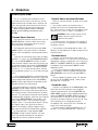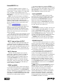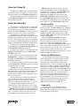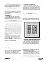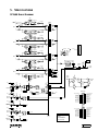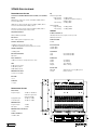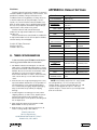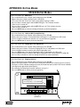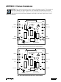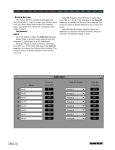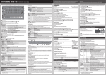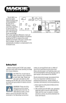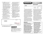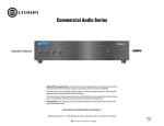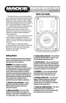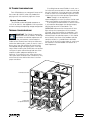
1
AC Power Considerations
Each SP2400 draws an average of 6 amps of AC
line current (@ 120VAC) when fully loaded and
playing music with a relatively high crest factor.
Voltage Conversion
The SP2400 can be configured to operate at
115V AC or 230V AC. See Appendix C for instructions
on how to change the operating voltage configuration.
Thermal Considerations
IMPORTANT: The SP2400 is convection
cooled rather than fan cooled. This design
was chosen to avoid the requirement for
periodic air filter maintenance, and to keep the
insides of the SP2400 clean in dirty environments
(rather than blowing dirty, smoky air into it). Heat is
drawn away from the amplifiers by the heatsinks
and radiated through the cooling vents in the top
cover. When installing the SP2400, be sure to allow
sufficient air space around the top and rear of the
amplifier to allow adequate cooling for the
heatsinks. If installing in a rack, leave at least one
rack space above and below the SP2400 for a vent,
and at least 6 inches behind the chassis to allow
proper ventilation.
If installing three or more SP2400s in a rack, use a
fan in the rack to move cool air in and warm air out of
the rack's enclosure. It may be necessary to provide
a cool air intake fan at the bottom of the rack, and a
warm air exhaust fan at the top (see Figure below).
Note: Though it is not required, it is
recommended that a warm air exhaust fan be used
when two SP2400s are installed in the same rack.
If the amplifier should overheat, a thermal switch
is activated that disengages the speaker outputs,
allowing the heatsinks to cool down. The
OVERLOAD indicator on the front panel will also
light to show that a protection circuit has been
activated. Once the amplifier has cooled to a safe
operating temperature, the thermal switch resets
and reactivates the speaker outputs. If this should
occur, identify the cause of the problem and take
corrective action (i.e., provide better ventilation,
install a fan in the rack to move more air, make sure
the amplifier is not overloaded with too low of a
load impedance).
r
t Ai t
Ho haus
x
E
2U Exhaust Fan Panel
1U Vent Panel
ir
ol A
Co ntake
I
1U Vent Panel
ir
ol A
Co ntake
I
2U Vent Panel
(or Optional Intake Fan)
ir
ol A
Co ntake
I
ir
ol A
Co ntake
I
ir
ol A
Co ntake
I
SP2400 – 15
4. Operation
SP2400 Quick Start
This isn’t a substitute for reading the entire
instruction manual, which is the only way to fully
understand how the SP2400 works. However, the
Quick Start provides a quick overview so you can
get the SP2400 set up and working right away.
Make sure the power switch is off while
setting up and making connections to the
SP2400.
External Switch Settings
• The Paging Mic and the Local Mic have +24 VDC
PHANTOM power switches. Move the switches
down to activate the phantom power if you are
using condenser microphones.
Internal Switch and Jumper Settings
Refer to “Internal Settings” on page 13 for more
information.
• Bus Assign switches are used to assign a
program input source to the balanced expansion
bus. There are four switches for each program input
source: Left (+), Left (–), Right (+), and Right (–).
CAUTION : Never assign more than one
program source to each of the four
expansion bus outputs.
• EQ Bypass allows you to bypass the 3-band EQ,
which is in the Input 1-4 signal path. EQ engaged is
the default setting.
• The Paging Mic and Local Mic also have GAIN
+40dB switches. Leave the switches in the down
position when microphones are connected to these
inputs.
• The amplifier can be configured for 8-ohm, 70V
(default), or 100V operation via eight jumpers on the
amplifier board.
• If you plan on connecting two or more SP2400s
together in a system with the EXPANSION IN/OUT
bus, use the LOCAL/REMOTE switches to select
either the local Program Input source (switches up)
or a remote program source from the EXPANSION
IN/OUT bus (switches down). The odd-numbered
switches (1, 3, 5, 7) select the left inputs, and the
even-numbered switches (2, 4, 6, 8) select the right
inputs.
Connect any stereo line-level signal source to
the Program Inputs 1-4. If you have a music-on-hold
requirement, connect a continuous music source to
INPUT 1. The DIRECT OUTPUT jacks next to INPUT 1
can feed the signal connected to INPUT 1 to the
telephone system.
If you have a need for a priority Program Input
(e.g., a jukebox), connect it to INPUT 4. Move the
AMP ADDRESS switch #7 UP to enable INPUT 4
priority.
Set the 3-band EQ controls to the “U” position
for now (1K for the FREQ control). These can be
adjusted later, if necessary.
• If you’re using the SP2400 in a stereo configuration,
move the STEREO/MONO switches up. If you have
a zone configuration planned, leave the STEREO/
MONO switches down (default) to combine the left
and right channels into a mono signal.
Program Inputs
Paging Mic Input
• For stereo operation, assign the same AMP
ADDRESS setting to both amplifiers (set the AMP
ADDRESS DIP switch #6 to the Master position on
one channel and to the Slave position on the other
channel). The front panel and remote control panels
will operate both amplifiers when they are assigned
to the same AMP ADDRESS. For example, if you
select Program Input 1 with the Zone A control,
Program Input 1 is also selected in Zone B, routing
the Program Input 1 left signal to the Zone A
(Stereo Left) amplifier, and the Program Input 1
right signal to the Zone B (Stereo Right) amplifier.
• For zone operation, assign different AMP
ADDRESS settings to each amplifier. The front
panel and remote control panels will operate
independently for each amplifier and zone.
SP2400 – 16
Connect a microphone to the PAGING MIC input.
Use either the XLR connector, or the supplied
Phoenix-type connector. Set the PHANTOM and
GAIN +40dB switches to their appropriate positions.
Adjust the MASTER VOLUME up/down buttons so
the meter level is at the “0” mark. Set the GAIN
control so the meter indication is near the “0” mark
when speaking at an average level into the
microphone. See “Setting The Vox Threshold” on
page 19 for more information.
Set the 2-band EQ (LOW and HIGH) to the “U”
position. This can be adjusted later, if necessary.
Paging Mic Control
The PAGING MIC CONTROL connector is
provided to connect a manual paging switch.
Connect a normally-open switch between GND and
ZONE A (to page in Zone A only), GND and ZONE B
(to page in Zone B only), or GND and ALL CALL
(to page over the entire system). The voiceactivated (VOX) control for the Paging Mic still
operates in both zones when the switch is off.
Expansion In/Out
If you are connecting two or more SP2400s in a
system, use the EXPANSION IN/OUT connections
to distribute the Program Input sources assigned to
the Expansion Bus between SP2400s. The two 25pin D-Sub connectors are in parallel (use one to
connect to the previous SP2400 and one to connect
to the next SP2400 in the chain).
REMOTE
Local Mic/Line Inputs
Connect a microphone to MIC/LINE INPUT A or B
(one for each zone), using the supplied Phoenix-type
connector, to use for a meeting room or other local
speaking requirements. Set the PHANTOM and
GAIN +40dB switches to their appropriate positions.
Select the OFF button on the front panel. This
disengages the selected Program Source and
engages the MIC/LINE INPUT. Adjust the MASTER
VOLUME up/down buttons so the meter level is at
the “0” mark.
Note: The MASTER VOLUME setting for the
MIC/LINE INPUTS is independent of the MASTER
VOLUME setting for INPUTS 1-4. The MASTER
VOLUME setting for INPUTS 1-4 is stored in
memory when the MIC/LINE INPUT is selected (the
OFF button is engaged). When an INPUT 1-4 is
selected, the MASTER VOLUME setting for the
MIC/LINE INPUT is stored in memory.
Set the GAIN control so the meter indication is
near the “0” mark when speaking at an average
level into the microphone.
Set the 2-band EQ (LOW and HIGH) to the “U“
position. These can be adjusted later, if necessary.
You can connect one or more optional remote
controls (up to 10) to each zone on the SP2400 to
provide wall-mounted input select, program signal
volume control, and local mic volume control.
RS485
A PC can be connected to the RS485 port to
provide computer control for up to 16 SP2400s,
interconnected via their RS485 ports, using the
SPLinker Sound Palette Control software application.
If the PC doesn't have an RS485 serial port, you can
either install an RS485 interface card, or use an
RS232 serial port with an RS232-to-RS485 converter.
Two zones can be controlled with one wired
remote control by connecting the RS485 ports
between the two zones. (The RS485 ports are
connected internally, so an external connection
between the RS485 ports on a single SP2400 is not
necessary.) Each amplifier must have the same
AMP ADDRESS as the amp to which the remote
control is connected, with one assigned as Master
and the other as Slave. Use the supplied Phoenixtype connectors to make these connections.
Note: Move the AMP ADDRESS switch #6
DOWN for Master and UP for Slave.
Ambient Mic Inputs
This is an optional connection, but can greatly
enhance the performance of the Paging Mic.
Connect the optional MT-3100 mic to the AMBIENT
MIC input (one for each zone). This provides an
“ear” for the microprocessor to adjust the Paging
Mic gain to compensate for the ambient noise level
in the room. Use the supplied Phoenix-type
connectors to make these connections.
Note: Move the AMP ADDRESS switch #8 UP to
enable the ambient mic. See page 20 for more
information on "Using the Ambient Mic."
PRE OUT/AMP IN
These connections can be used to insert a signal
processor (i.e., graphic equalizer, compressor, etc.)
into the signal chain, or to feed the signal to additional
power amplifiers. If no external processor or external
amplifier is to be used, leave the U-shaped jumper in
place between the PRE OUT and AMP IN connectors.
OUTPUTS
Use the supplied two-conductor Phoenix-type
connectors with appropriate speaker wiring to
connect to the speaker or distributed speaker
system.
SP2400 – 17
Using INPUTS 1-4
Connect the program sources to Inputs 1-4.
These could include a CD player, tape deck, tuner,
satellite feed, TV audio, jukebox, or an audio feed
from a live band. All four program inputs use
unbalanced RCA connectors and accept stereo linelevel signals.
Note: The Input Select buttons are labeled 1
through 4 on the front panel. The spaces below the
buttons are sized to accept 1/4" labels from the
Brother P-Touch Electronic Labeling System.
Professional-looking labels can be made to clearly
identify the program source connected to each
input (visit www.brother.com).
There are no individual volume controls for
Inputs 1-4. The SP2400 automatically adjusts the
volume for each input using an AGC circuit
(Automatic Gain Control). This provides the best
signal-to-noise ratio and insures that the volume
remains the same when you switch from one
source to another.
Only one Input source can be selected at a time.
When switching from one source to another, the
previous source fades out while the new source
fades in (digital crossfade), rather than abruptly
switching between the two.
INPUT 1 and the Direct OUTPUT
Input 1 provides a direct line-level output that
can be used for music-on-hold or other external
applications. Connect a continuous music source
(i.e., satellite feed, prerecorded background music,
multi-disc CD player) to Input 1 and connect the
DIRECT OUTPUT jacks to the external destination.
INPUT 4 Priority
Normally, the four program inputs are nonpriority inputs. However, if there is a jukebox or
other priority program source in the system,
Program Priority can be activated on Input 4 by
setting AMP ADDRESS switch #7 UP. When a
signal appears at Input 4, it overrides the other
three inputs. When the signal stops, the SP2400
switches back to the previously selected input
source, fading it in smoothly.
STEREO or MONO
The four program inputs accept stereo signals.
The SP2400 can be operated in a stereo configuration or a zone configuration. The STEREO/MONO
switches should be set to the up position for stereo
operation. Set the AMP ADDRESS switches to the
same address to allow the front panel and remote
control panels to operate both amplifiers.
SP2400 – 18
In a zone configuration, move the STEREO/
MONO switches down to combine the stereo signal
into a mono signal for each program source. Set the
AMP ADDRESS switches to different addresses to
allow independent control over each zone.
LOCAL or REMOTE
These switches are used to select the input
source for each of the four Program Inputs. Leave
the switches up to select the local input source
connected to the PROGRAM INPUT connector.
Move the switches down to select the remote
signal coming from the EXPANSION IN connector.
Each Program Input has two switches, one for the
left input and one for the right input.
Bus Assign
These internal switches are used if you have two
or more SP2400s connected together in a system
using the EXPANSION IN/OUT connectors. Each of
the four program inputs can be individually assigned
to the EXPANSION balanced bus. There are four
switches associated with each Program Input source
(see the Bus Assign Switch chart on page 13).
Caution: Never assign more than one program
source to each of the four expansion bus outputs.
EXPANSION IN/OUT
These two 25-pin D-Sub connectors are used to
connect two or more SP2400s together so they can
share program sources. This is a true balanced bus
and transmits the left and right signal from each of
the four inputs over balanced lines. Refer to the
“Connections” section on page 12 for information
on wiring these connectors.
These connections allow a common program
source to be available to all the SP2400s in a
system. For example, prerecorded music that is
used for music-on-hold can also serve as background
music for an entire office building by setting the
internal bus assign switches for Input 1 to the up
position on the first SP2400. The music is then
available to Input 1 on all the SP2400s connected
via the EXPANSION IN/OUT connectors when their
LOCAL/REMOTE switches are set to the REMOTE
position (down).
Note: Switching the LOCAL/REMOTE switch to
REMOTE doesn't disconnect the local input. If a
different program source is connected locally to
Input 1 on one of the SP2400s in the above
example, both the common program source (the
remote prerecorded music) and the local program
source will be combined on Input 1 and can be
played simultaneously. Typically, a local program
source would not be connected to an Input which
has REMOTE selected as the source.
Using the 3-Band EQ
This equalizer is applied to the selected program
source from Inputs 1-4, whether it is a local source
or remote source (via the EXPANSION IN/OUT bus).
This equalizer does not affect the paging mic or
the local MIC/LINE INPUTS, which each have their
own 2-band EQ controls.
Note 2: When the manual switch is off, the
voice-activated (VOX) control for the paging mic is
still operational. Ensure that the PAGING MIC VOX
threshold is set accordingly to prevent false
triggering of the paging mic input when using
PAGING MIC CONTROL switching. Alternatively,
turn the PAGING MIC VOX control all the way up
(fully clockwise) to defeat the VOX circuit. Note that
each zone has its own PAGING MIC VOX control.
Using the Paging Mic
Setting the GAIN
The paging mic is used to make announcements
over the system. If the paging mic is a condenser
mic or other type of mic that requires phantom
power, move the PHANTOM switches to the down
position. Otherwise, leave them switched up.
The paging mic can be voice-activated and is
routed to both channels or zones. However, you have
the option of activating it manually with an external
switch. If you choose to use a switch for the paging
mic, you have the additional option of assigning the
paging mic to either Zone A or Zone B, or to both zones.
• For Zone A only, connect a (normally-open)
switch between the ZONE A and GROUND pins on
the PAGING MIC CONTROL connector.
• For Zone B only, connect a switch between the
ZONE B and GROUND pins on the PAGING MIC
CONTROL connector.
• For all zones in a system interconnected via the
EXPANSION bus, connect a switch between the
ALL CALL and GROUND pins on the PAGING MIC
CONTROL connector.
• For maximum flexibility, connect three switches
to the PAGING MIC CONTROL connector and have
all three selections available.
The paging mic can be configured to automatically
turn down (duck, or attenuate) the music that is
playing over the system so the announcement can
be heard when using the VOX circuit. When an
announcement is over, the music gradually returns
to its original volume.
The music ducks fairly rapidly, attenuating the
music 20 dB within 300 ms (milliseconds) of
detecting a signal on the paging mic. When the
signal on the paging mic stops, there is a 1500 ms
(1.5 second) timeout period to make sure the
announcement is over, and then the music ramps
up to its original volume over the next 2.5 seconds.
Note 1: When manually activating the paging mic,
there is no timeout period after the announcement
ends. The moment you let go of the switch, the
music begins to ramp up to its original volume.
When a microphone is connected directly to the
paging mic input, the GAIN +40dB switch should be
set in the down position (for a mic-level signal). When
the paging mic is going through an external mixer,
sending a line-level signal to the paging mic input,
move the GAIN +40dB switch to the up position (for
a line-level signal only).
Adjust the MASTER VOLUME control by
pressing the up/down buttons so the meter
indicates a level at the “0” mark. With all music
sources off, speak into the paging mic with a
normal voice. Adjust the PAGING MIC GAIN control
with a non-conductive alignment tool so that the
meter indication is near the “0” mark. This provides
the best signal-to-noise ratio for the mic, and
insures that the signal from the paging mic is strong
enough to trigger the VOX circuit.
Setting the VOX Threshold
This control determines how strong the signal
from the paging mic must be to trigger the VOX
circuit, which ducks the program source when an
announcement is made. Ideally, the threshold
should be set so it is sensitive enough to trigger the
VOX circuit as soon as you begin speaking, but not
so sensitive as to be triggered by ambient sounds
around the microphone. Set the PAGING MIC VOX
control to the center position with a non-conductive
alignment tool to start. Turn the control counterclockwise to lower the threshold (increase the
sensitivity) if the beginning of announcements are
getting clipped off. Turn the control clockwise to
increase the threshold (decrease the sensitivity)
should you experience false triggering due to
ambient noise around the microphone.
Using the EQ
The paging mic has a 2-band equalizer for
adjusting the lows or highs on the microphone
signal. When the controls are set to “U” (unity), the
EQ has no effect on the signal.
SP2400 – 19
Using the AMBIENT MIC
The ambient mic is an optional accessory (MT3100) that is available for the SP2400, which is used
to sense the ambient noise level in the room. Set
the AMP ADDRESS switch #8 up to enable the
ambient mic, otherwise leave the switch down.
The ambient mic provides an “ear” for the microprocessor to gauge the ambient noise in the room and
adjust the gain of the paging mic accordingly. When
the background noise is relatively quiet, the paging
mic gain is at its lowest level. If the background
noise is relatively loud, the paging mic gain is at its
highest level. If the background noise is somewhere in between, the paging mic gain is midway
between its lowest and highest preset levels.
Ambient Mic Calibration and Placement
1. Connect the MT-3100 (or other microphone) to the
AMBIENT MIC connector on the rear panel. Make sure
the ambient mic switch is on (AMP ADDRESS switch
#8 up). Locate the ambient mic in an appropriate
position to pick up the ambient noise in the room. It
can be mounted on the ceiling or on a wall. Avoid
placing the ambient mic close to the speaker over
which the announcement is being made. Keep the
ambient mic away from a constant noise source, such
as a refrigerator or other mechanical device that emits
a continuous noise. The best placement is where the
mic can pick up an average representation of the
ambient noise level in the room.
Note: Each zone or channel must be calibrated
individually.
2. Turn off the SP2400, then turn it back on again while
pressing and holding the Input 2 button. This causes
the ambient mic preamp level to appear on the meter.
3. Establish the highest noise level that you would
expect to have in the room using a pink or white noise
source, or a music source. Input 1 is operational in this
mode to use as a music source, if desired.
3. Adjust the MASTER VOLUME control by pressing the
Up/Down buttons so the meter indicates a level at the
“0” mark.
4. Adjust the PAGING MIC GAIN control as high as it will
go before feedback occurs while speaking into the
paging microphone.
5. Switch the ambient mic on (AMP ADDRESS switch
#8 up).
6. Turn off the SP2400, then turn it back on again while
pressing and holding the “3” button.
7. Release the Input 3 button after a few seconds and
the third LED starts flashing slowly.
8. Use the front panel Up/Down buttons to set the lower
level of the paging mic (how loud it is with very quiet
background noise). It should be loud enough to be
heard clearly throughout the coverage area.
9. Press the “OFF” button and the level is stored. The
third LED starts flashing faster.
10. Use the front panel Up/Down buttons to set the upper
level of the paging mic (how loud it is with very loud
background noise). As a general rule, set this level as
high as it will go before feedback (at the "0" mark if
steps 3-4 above were followed).
11. Press the Input 3 button when finished to store the
level and return to normal operation.
12. Verify that the paging microphone’s volume is sufficient
to be heard over the background noise in the room.
Note: For best results, with the background noise
level at a minimum, the paging mic volume should be
approximately the same as the music volume.
13. If the paging microphone is not loud enough to be
heard over the background noise, verify that the
ambient mic is properly placed to pick up an accurate
representation of the background noise. If it is, it may
be necessary to readjust the lower and upper levels
for the paging mic gain (steps 6-11).
Using the Local Mic/LINE INPUT
4. Adjust the ambient mic preamp gain trim (located just
above the ambient mic connector on the rear panel,
through the unmarked hole) with a non-conductive
alignment tool until all the green LEDs on the meter are
lit. Insure that no yellow or red LEDs are lit, which runs
the risk of clipping the ambient mic preamp or ADC.
5. Press the “OFF” button when finished to return to
normal operation.
The MIC/LINE INPUT A and B is provided for
each zone to connect a microphone for a speaker in
a conference room, or similar sound reinforcement
applications. If the local mic is a condenser mic,
move the PHANTOM switches to the down position.
Setting the GAIN
Paging Microphone Calibration Procedure (when used with Ambient Mic)
1. Perform the “Ambient Microphone Calibration
Procedure” described above.
2. Switch the ambient mic OFF (AMP ADDRESS switch
#8 down).
SP2400 – 20
When a microphone is connected directly to the
MIC/LINE INPUT, the GAIN +40dB switch should be
set in the down position (for a mic-level signal).
When the mic is going through an external mixer,
sending a line-level signal to the input, move the
GAIN +40dB switch to the up position (for a linelevel signal only).
Press the OFF button to select the MIC/LINE
INPUT. Adjust the MASTER VOLUME control by
pressing the up/down buttons so the meter
indicates a level at the “0” mark. With all music
sources off, speak into the mic with a normal voice.
Adjust the MIC/LINE INPUT GAIN control with a
non-conductive alignment tool so that the meter
indication is near the "0" mark. This provides the
best signal-to-noise ratio for the mic and insures
that its relative volume will be equivalent to the
program sources.
Using the EQ
Each local MIC/LINE INPUT has a 2-band
equalizer for adjusting the lows or highs on the
microphone signal. When the controls are set to
“U” (unity), the EQ has no effect on the signal.
Distributed Speaker System
When using the SP2400 in a 70V or 100V
system, connect the speaker outputs directly to the
distributed system. The SP2400 can directly drive a
distributed system's speaker line without the need
for an output transformer. The SP2400 can supply
up to 200 watts into a 70V or 100V distributed
system. Make sure the taps on the speakers in
the system do not exceed a total of 200 watts.
Using the REMOTE Connection
The optional SP2400 Remote Control (SP-41R)
provides Input Selection and Master Volume control
for each amplifier or zone. The Remote Control can
be mounted in a standard double-gang electrical
box and covered with a Decora®-style faceplate.
Using the PRE OUT/AMP IN Connections
The PRE OUT and AMP IN connectors are
provided to give you more flexibility in your system
design. The SP2400 is shipped with U-shaped
jumpers installed between the PRE OUT and AMP
IN jacks. This routes the signal from the output of
the preamplifier stage to the input of the amplifier
stage.
This also provides a point in the signal chain to
insert an external signal processor. Simply connect
the line-level signal from the PRE OUT jack to the
input of the processor, and connect the line-level
output from the processor to the AMP IN jack on
the SP2400.
Another option that is available is to connect
another amplifier into the system. Simply use a
Y-cord at the PRE OUT jack to split the signal
between the AMP IN jack and the input jack on an
external amplifier.
LEFT and RIGHT OUTPUTs
The amplifier outputs on the SP2400 can be
used with an 8-ohm impedance load, or to directly
drive a 70V or 100V distributed system (also called
constant-voltage systems).
Direct Speaker Connection
If the SP2400 is not being used in a distributed
speaker system, you can reconfigure the amplifiers
to drive an 8-ohm load. Each amplifier can provide
up to 250 watts into an 8-ohm load. See the
"Internal Settings" section on page 14 for
instructions on how to reconfigure the amplifiers.
3
0
3
6
9
15
30
55
Connecting One or More Remote Controls
Each Remote Control affects only the zone to
which it is connected. Up to ten remote controls
may be connected to each zone simultaneously.
This allows controls to be conveniently placed.
Each control will interact with the SP2400, and all
controls will reflect the current source and level
settings. Note that the remote control indicates the
gain setting and not the actual signal level in real
time. In addition, the SP2400 provides a method for
controlling two independent zones using a single
Remote Control by assigning them to the same
AMP ADDRESS (see next section).
The maximum distance between the remotes
and the SP2400 varies, depending on the type of
cable selected and the number of remote controls
used. Typically, a lower wire gauge and cable
capacitance allow longer distances. See the instructions with the remote control for more information.
SP2400 – 21
Using the RS485 Connection
Each amplifier is equipped with an RS485
connection. These connectors are linked internally,
so if both amplifiers have the same AMP ADDRESS
assignment, the Input Selection and MASTER
VOLUME buttons track each other, since they are
assigned to the same zone. One side must have
AMP ADDRESS switch #6 in the Master position
(up), and the other side in the Slave position (down).
The same thing can be accomplished between
two SP2400s by connecting the amplifiers together
with the RS485 connection. Again, be sure that
both amplifiers are assigned to the same zone
(AMP ADDRESS switches 1-5), one is configured as
Master and the other Slave, and that no other
amplifiers are connected via the RS485 port with
the same AMP ADDRESS.
In this way, you can have one Remote control
operate both amplifiers that are assigned to the
same zone.
Note: The microprocessor polls the AMP
ADDRESS switch when it initializes at power-up. If a
change is made to the AMP ADDRESS switch, turn
the SP2400 off for five seconds, then turn it back
on again for the new settings to take effect.
Using the SPLinker Sound Palette
Controller
The RS485 connection can also be used to
connect the SP2400 to a computer loaded with the
SPLinker software application. The PC-compatible
computer must have an RS485 port to properly
connect to the SP2400. It may be necessary to
install an RS485 interface card, or use an RS232
port with an RS232-to-RS485 converter.
SP2400 – 22
The SPLinker is a PC-based graphical interface to
provide real-time monitoring and control for up to 32
zones. It provides individual program source
selection and volume control for each zone. Select
boxes are located at the bottom of each zone for
selecting multiple zones. All selected zones can
then be modified at the same time in the Multiple
settings box located on the right-hand side of the
screen.
Using a 3rd Party Control System
The RS485 connection can also be used to
interface with common third-party control systems.
Contact the third-party provider or Mackie Industrial
Technical Support to determine if your control
system is compatible with the SP2400.
Upgrading the Software
From time to time, Mackie Industrial will release
upgrades for the internal operating software in the
SP2400. This can be downloaded from our website
(www.mackieindustrial.com) to a PC-compatible
computer. Use the serial port on the computer to
connect to internal connectors on the SP2400's
CPU boards to transfer the data to the on-board
flash memory. Instructions will be provided when
upgrades are available.
5. Specifications
SP2400 Block Diagram
BUS
ASSIGN
+
—
DIRECT L
OUTPUT R
+
TO EXPANSION I/O
+ FROM
EXPANSION
—
I/O
—
LOCAL/REMOTE
+
DIGITALLY
CONTROLLED
ATTENUATORS
—
L
STEREO/
MONO
INPUT 1
R
TO ZONE B
+
FROM
EXPANSION
—
I/O
+
—
LOCAL/REMOTE
+
—
+
BUS
ASSIGN
—
TO EXPANSION I/O
+
—
+
+ FROM
EXPANSION
—
I/O
—
+
—
LOCAL/REMOTE
L
STEREO/
MONO
INPUT 2
R
TO ZONE B
+
FROM
EXPANSION
—
I/O
+
—
LOCAL/REMOTE
+
3
0
3
—
+
BUS
ASSIGN
WOODINVILLE
—
TO EXPANSION I/O
+
—
6
FROM µP
9
15
—
+
+ FROM
EXPANSION
—
I/O
—
+
REDMOND
MACKIE
INDUSTRIAL
LOCAL/REMOTE
30
55
L
STEREO/
MONO
INPUT 3
R
TO ZONE B
+
FROM
EXPANSION
—
I/O
+
—
LOCAL/REMOTE
+
LO
+
BUS
ASSIGN
—
+
+ FROM
EXPANSION
—
I/O
—
+
MID FREQ
HI
J6
EQ
BYPASS
12K
80
—
TO EXPANSION I/O
+
—
TO µP
ADC
PROGRAM EQ
—
DIGITALLY
CONTROLLED
ATTENUATOR
J4
INSERT
(INTERNAL
FOR OPTIONAL
DSP CARD)
LOCAL/REMOTE
ZONE A
PRE OUT
L
STEREO/
MONO
INPUT 4
R
VOX
ACTIVATION
TO µP
TO ZONE B
+
+ FROM
EXPANSION
—
I/O
—
+
LOCAL/REMOTE
+
VOX
ACTIVATION
TO µP
—
V+
ZONE A
AMP IN
TO EXPANSION I/O
—
OVERLOAD
BUS
ASSIGN
+24VDC
PHANTOM
GAIN
+40dB
V—
TO EXPANSION I/O
MIC
+ —
FROM
TEMP
SENSOR
(ON HEATSINK)
LEFT/ZONE A
OUTPUT
+
PROTECTION
(TO µP)
GAIN
—
V+
PAGING
MIC VOX
2
+
LO
HI
80
12K
70V/100V
8Ω
1
PAGING MIC
—
3
1
GAIN
+40dB
+24VDC
PHANTOM
MIC/LINE
INPUT A
ZONE A
ZONE B
ALL CALL
GND
PAGE MIC
SWITCH
CONTROL
EXPANSION IN
TO ZONE B
–15VDC (w/J2 INSTALLED)
N/C
PAGING MIC (+)
INPUT 4 RIGHT (+)
INPUT 4 LEFT (+)
INPUT 3 RIGHT (–)
INPUT 3 LEFT (–)
GROUND
INPUT 2 RIGHT (+)
INPUT 2 LEFT (+)
INPUT 1 RIGHT (–)
INPUT 1 LEFT (–)
GAIN
1
3
LO
HI
80
12K
GAIN
+40dB
+24VDC
INTERNAL
TRIM
PHANTOM
AMBIENT MIC
(ZONE A)
PAGING
MIC VOX
VOX
GAIN
+40dB
V—
(TO µP)
3
25
14
1
13
1
+15VDC (w/J3 INSTALLED)
PAGING MIC CONTROL
PAGING MIC (–)
INPUT 4 RIGHT (–)
INPUT 4 LEFT (–)
GROUND
INPUT 3 RIGHT (+)
INPUT 3 LEFT (+)
INPUT 2 RIGHT (–)
INPUT 2 LEFT (–)
GROUND
INPUT 1 RIGHT (+)
INPUT 1 LEFT (+)
TO µP
ADC
3
+24VDC
PHANTOM
MIC/LINE
INPUT B
GAIN
1
LO
HI
80
12K
TO ZONE B
3
GAIN
+40dB
+24VDC
PHANTOM
AMBIENT MIC
(ZONE B)
GAIN
+40dB
ATTENUATOR
CONTROL
(FROM µP)
INTERNAL
TRIM
1
ADC
TO µP
MACKIE INDUSTRIAL
SP2400
BLOCK DIAGRAM
(#01.02.01.DF)
–15VDC (w/J2 INSTALLED)
N/C
PAGING MIC (+)
INPUT 4 RIGHT (+)
INPUT 4 LEFT (+)
INPUT 3 RIGHT (–)
INPUT 3 LEFT (–)
GROUND
INPUT 2 RIGHT (+)
INPUT 2 LEFT (+)
INPUT 1 RIGHT (–)
INPUT 1 LEFT (–)
25
14
13
1
+15VDC (w/J3 INSTALLED)
PAGING MIC CONTROL
PAGING MIC (–)
INPUT 4 RIGHT (–)
INPUT 4 LEFT (–)
GROUND
INPUT 3 RIGHT (+)
INPUT 3 LEFT (+)
INPUT 2 RIGHT (–)
INPUT 2 LEFT (–)
GROUND
INPUT 1 RIGHT (+)
INPUT 1 LEFT (+)
EXPANSION OUT
3
SP2400 – 23
SP2400 Specifications
Power Amplifier Section
EQ
Continuous Sine Wave Average Output Power, both channels
driven:
3-Band Program EQ:
High Shelving:
Mid Peaking:
200 watts per channel into 8 ohms from 20Hz to 20kHz, with no
more than 0.01% THD
100V rms per channel into 50 ohms from 20Hz to 20kHz, with no
more than 0.1% THD (J2/J3 in 100V position)
70V rms per channel into 25 ohms from 20Hz to 20kHz, with no
more than 0.1% THD (J2/J3 in 70V position)
Low Shelving:
2-Band Mic EQ:
High Shelving:
Low Shelving:
±15 dB @ 12kHz
±15 dB with sweepable frequency
(250Hz to 8kHz)
±15 dB @ 80Hz
±12 dB @ 12kHz
±12 dB @ 100Hz
General
Frequency Response
Power Consumption
20Hz to 20kHz (+0, –0.5 dB)
Distortion
700 watts with musical program, 8 ohms per side
800 watts maximum
THD: < 0.01% @ rated output into 8 ohms
Phantom Power
Signal-To-Noise Ratio
24 VDC
> 90 dB below rated power into 8 ohms
> 100 dB (A-weighted) below rated power into 8 ohms
AC Line Voltage
Channel Separation
115VAC, 60Hz
230VAC, 50Hz
> 80 dB @ 1kHz
Fuse Rating
Amp Input Impedance
115V
230V
20K ohms
Dimensions
Input Sensitivity
+5 dBu (1.37V rms) for rated power into 8 ohms
Gain
27 dB (8-ohm position)
27 dB (70V position)
30 dB (100V position)
MT-3100
SP-41R
12 volts P-P (+15 dBu)
Rise Time
< 5 µS
Slew Rate
> 17 V/µS
Preamplifier Section
Input Levels
Paging Mic Input:
Local Mic Input:
–10 dBu to +10 dBu for
maximum output level
with internal AGC
–52 dBu to +4 dBu
–52 dBu to +4 dBu
Maximum Input
Program Inputs:
Mic Inputs:
+15 dBu
+15 dBu
Maximum Output at Pre Out
+10 dBu
Stereo Separation
> 45 dB at 1kHz
SP2400 – 24
Height:
Width:
Depth:
Weight:
3.5" (88mm)
19" (483mm)
16.7" (424mm)
40 lbs. (18.1kg)
Accessories
Maximum Input Level
Program Inputs:
8A Slow Blow, 250V
4A Slow Blow, 250V
Ambient Noise Sensing Microphone
Remote Control
Disclaimer
Mackie Industrial continually engages in research
related to product improvement, new materials, and
production methods. Design refinements are
introduced into existing products without notice as
a routine expression of that philosophy. For this
reason, any current Mackie Industrial product may
differ in some respect from its published description,
but will always equal or exceed the original design
specifications unless otherwise stated.
Mackie Industrial and Sound Palette are
trademarks or registered trademarks of Mackie
Designs Inc.
All other brand names mentioned are trademarks
or registered trademarks of their respective holders,
and are hereby acknowledged.
© 2001 All Rights Reserved.
Mackie Industrial.
Printed in the U.S.A.
6. Service Information
In the event that your SP2400 should require
servicing, please follow these instructions:
1. Call Mackie Industrial Tech Support at 1-888-3377404, 8 am to 5 pm PST (Monday-Friday), to verify
the problem and obtain a Return Authorization (RA)
Number. Be sure to have the serial number of the
unit when you call. You must have a Return
Authorization Number in order to obtain warranty
service at the factory or at an authorized service
center.
2. Pack the unit in its original packaging. This is very
important. Mackie Industrial is not responsible for
any damage that occurs during shipping due to
non-conventional packaging. Original packaging
helps to minimize the possibility of shipping
damage.
APPENDIX A: Default Settings
Control
Setting
LOCAL/REMOTE
UP (LOCAL)
STEREO/MONO
DOWN (MONO)
PAGING MIC
PHANTOM
UP (OFF)
GAIN +40dB
UP (0dB)
GAIN
CENTER
LOW
CENTER (FLAT)
HIGH
CENTER (FLAT)
ZONE A
ZONE B
AMP ADDRESS
10000000
01000000
MIC/LINE INPUT
GAIN
CENTER
CENTER
LOW
CENTER (FLAT)
CENTER (FLAT)
HIGH
CENTER (FLAT)
CENTER (FLAT)
PHANTOM
UP (OFF)
UP (OFF)
GAIN +40dB
UP (0dB)
UP (0dB)
MIC VOX
DOWN (OFF)
DOWN (OFF)
PROGRAM EQ
LOW
CENTER (FLAT)
CENTER (FLAT)
MID
CENTER (FLAT)
CENTER (FLAT)
FREQ
CENTER (1kHz)
CENTER (1kHz)
HIGH
CENTER (FLAT)
CENTER (FLAT)
INTERNAL BUS
ASSIGN (S1/S2)
OFF
NOTE: All SP2400s sold in the U.S. and Canada
are configured for 115V AC line input and 70V
speaker output. All units sold outside the U.S. and
Canada are configured for 230V AC and 100V
speaker outputs. Please confirm your configuration
prior to installation.
3. Include a legible note stating your name, return
shipping address, (no P.O. boxes), daytime phone
number, Return Authorization Number, and a
detailed description of the problem, including how
we can duplicate it.
4. Write the Return Authorization Number in BIG
BOLD PRINT on the top of the box.
5. Ship the unit to us. We suggest insurance for all
forms of cartage. Ship to this address:
Mackie Industrial
Service Department
16140 Wood-Red Road NE, Suite 5
Woodinville, WA 98072
SP2400 – 25
APPENDIX B: Button Modes
SP2400 Button Modes
Press 1 on Power Up: AGC Reset
• Press and hold the Input 1 button while powering up the SP2400.
• Release the Input 1 button and the Input 1 LED blinks.
This resets the AGC for all four inputs to the default setting (–5 dBu).
• Press the Input 1 button again and the OFF LED lights. This indicates that the
AGC circuit is turned off.
• Press the Input 1 button again and the OFF LED turns off. This indicates that the
AGC circuit is turned on.
• Press the OFF button to save the settings and return to normal operation.
Press 2 on Power Up: Ambient Mic Preamp Metering
• Press and hold the Input 2 button while powering up the SP2400.
• Release the Input 2 button. The Ambient Mic Preamp gain is indicated on the LED meter.
• Use this mode to calibrate the ambient mic (see procedure on page 20).
• Press the OFF button to return to normal operation.
Press 3 on Power Up: Paging Mic Level Adjustment
• Press and hold the Input 3 button while powering up the SP2400.
• Release the Input 3 button. The lowest Paging Mic level is indicated on the LED meter.
• Use the Up/Down buttons to adjust the lowest Paging Mic level.
• Press the OFF button. The highest Paging Mic level is indicated on the LED meter.
• Use the Up/Down buttons to adjust the highest Paging Mic level (see procedure on page 20).
• Press the Input 3 button to save the settings and return to normal operation.
Press 4 on Power Up: Firmware Version
• Press and hold the Input 4 button while powering up the SP2400.
• Release the Input 4 button. The LEDs on the front panel indicate the firmware version in binary.
• The Input 1-4 LEDs indicate the digit to the left of the decimal point, and the LED meter indicates
the digit to the right of the decimal point.
• For example, the following illustration indicates version 1.7.
• Press the OFF button to return to normal operation.
3 LED pairs lit
111 (in binary) = 7 (in decimal)
Version 1.7
SP2400 – 26
APPENDIX C: Voltage Conversion
CAUTION: These servicing instructions are for use by qualified personnel only. To avoid electric
shock, do not perform any servicing other than that contained in the Operating Instructions
unless you are qualified to do so. Refer all servicing to qualified service personnel. Make sure
the power is off and the power cord disconnected before removing the top cover to gain access to the
inside of the SP2400.
JUMPER INSTALLED FOR 115V
J10
YELLOW/RED
RISK OF FIRE! REPLACE WITH FUSE AS MARKED
J14
BLUE
J12
C3
BROWN
J13
YELLOW
R3
D1
J7
YELLOW/RED
D2
K1
JP1
J11
4A SB 250V
+
R4
J6
YELLOW
J5
F1
R6
J8
R5
J9
C2
R2
J4
J3
BLACK
BLACK
J2
J1
R1
C1
BLACK/RED
®
BLACK/RED
MACKIE DESIGNS. ™
© 2000
055-286-00 REV:__
SP2400:SOFT START
SP2400: 115V AC CONFIGURATION
(8A, 250V SLOW BLOW FUSE INSTALLED IN IEC SOCKET)
REMOVE JUMPER FOR 230V
J10
RISK OF FIRE! REPLACE WITH FUSE AS MARKED
J14
BLUE
J12
C3
BROWN
J13
YELLOW
R3
D1
J7
K1
JP1
YELLOW/RED
R6
D2
J5
F1
J9
J8
BLACK
J4
J2
BLACK/RED
YELLOW/RED
C2
R2
R5
BLACK
J11
4A SB 250V
+
R4
J6
YELLOW
J3
J1
R1
C1
®
MACKIE DESIGNS. ™
© 2000
BLACK/RED
055-286-00 REV:__
SP2400:SOFT START
SP2400: 230 VAC CONFIGURATION
(4A, 250V SLOW BLOW FUSE INSTALLED IN IEC SOCKET)
SP2400 – 27
SP2400 Music Controller
Mackie Industrial
16220 Wood-Red Rd. NE • Woodinville, WA 98072 • USA
888/337-7404 • Outside the U.S.: 425/487-4333
Fax: 425/487-4337 • www.mackieindustrial.com