1
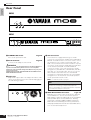
OWNER’S MANUAL
MUSIC PRODUCTION SYNTHESIZER
EN
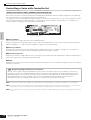
SPECIAL MESSAGE SECTION
This product utilizes batteries or an external power supply
(adapter). DO NOT connect this product to any power supply or
adapter other than one described in the manual, on the name
plate, or specifically recommended by Yamaha.
WARNING: Do not place this product in a position where
anyone could walk on, trip over, or roll anything over power or
connecting cords of any kind. The use of an extension cord is
not recommended! If you must use an extension cord, the
minimum wire size for a 25’ cord (or less) is 18 AWG. NOTE: The
smaller the AWG number, the larger the current handling
capacity. For longer extension cords, consult a local electrician.
This product should be used only with the components supplied
or; a cart, rack, or stand that is recommended by Yamaha. If a
cart, etc., is used, please observe all safety markings and
instructions that accompany the accessory product.
SPECIFICATIONS SUBJECT TO CHANGE:
The information contained in this manual is believed to be
correct at the time of printing. However, Yamaha reserves the
right to change or modify any of the specifications without
notice or obligation to update existing units.
This product, either alone or in combination with an amplifier
and headphones or speaker/s, may be capable of producing
sound levels that could cause permanent hearing loss. DO NOT
operate for long periods of time at a high volume level or at a
level that is uncomfortable. If you experience any hearing loss
or ringing in the ears, you should consult an audiologist.
IMPORTANT: The louder the sound, the shorter the time
period before damage occurs.
Some Yamaha products may have benches and / or accessory
mounting fixtures that are either supplied with the product or as
optional accessories. Some of these items are designed to be
dealer assembled or installed. Please make sure that benches
are stable and any optional fixtures (where applicable) are well
secured BEFORE using.
Benches supplied by Yamaha are designed for seating only. No
other uses are recommended.
Battery Notice:
This product MAY contain a small non-rechargeable battery
which (if applicable) is soldered in place. The average life span
of this type of battery is approximately five years. When
replacement becomes necessary, contact a qualified service
representative to perform the replacement.
This product may also use “household” type batteries. Some of
these may be rechargeable. Make sure that the battery being
charged is a rechargeable type and that the charger is intended
for the battery being charged.
When installing batteries, do not mix batteries with new, or with
batteries of a different type. Batteries MUST be installed
correctly. Mismatches or incorrect installation may result in
overheating and battery case rupture.
Warning:
Do not attempt to disassemble, or incinerate any battery. Keep
all batteries away from children. Dispose of used batteries
promptly and as regulated by the laws in your area. Note: Check
with any retailer of household type batteries in your area for
battery disposal information.
Disposal Notice:
Should this product become damaged beyond repair, or for
some reason its useful life is considered to be at an end, please
observe all local, state, and federal regulations that relate to the
disposal of products that contain lead, batteries, plastics, etc. If
your dealer is unable to assist you, please contact Yamaha
directly.
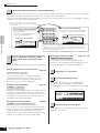
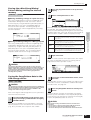
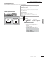
NAME PLATE LOCATION:
The name plate is located on the rear (MO8) or bottom (MO6) of
the product. The model number, serial number, power
requirements, etc., are located on this plate. You should record
the model number, serial number, and the date of purchase in
the spaces provided below and retain this manual as a
permanent record of your purchase.
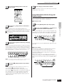
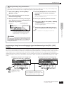
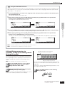
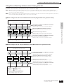
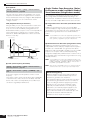
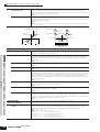
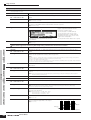
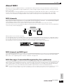
MO8
MIDI
USB
NOTICE:
TO DEVICE
TO HOST
THRU
OUT
IN
Service charges incurred due to a lack of knowledge relating to
how a function or effect works (when the unit is operating as
designed) are not covered by the manufacturer’s warranty, and
are therefore the owners responsibility. Please study this manual
carefully and consult your dealer before requesting service.
MO6
ENVIRONMENTAL ISSUES:
Yamaha strives to produce products that are both user safe and
environmentally friendly. We sincerely believe that our products
and the production methods used to produce them, meet these
goals. In keeping with both the letter and the spirit of the law, we
want you to be aware of the following:
Model
Serial No.
Purchase Date
PLEASE KEEP THIS MANUAL
FCC INFORMATION (U.S.A.)
1. IMPORTANT NOTICE: DO NOT MODIFY THIS UNIT!
This product, when installed as indicated in the instructions contained in this manual, meets FCC requirements. Modifications not
expressly approved by Yamaha may void your authority, granted by
the FCC, to use the product.
2. IMPORTANT: When connecting this product to accessories and/
or another product use only high quality shielded cables. Cable/s
supplied with this product MUST be used. Follow all installation
instructions. Failure to follow instructions could void your FCC
authorization to use this product in the USA.
3. NOTE: This product has been tested and found to comply with the
requirements listed in FCC Regulations, Part 15 for Class “B” digital
devices. Compliance with these requirements provides a reasonable level of assurance that your use of this product in a residential
environment will not result in harmful interference with other electronic devices. This equipment generates/uses radio frequencies
and, if not installed and used according to the instructions found in
the users manual, may cause interference harmful to the operation
of other electronic devices. Compliance with FCC regulations does
* This applies only to products distributed by YAMAHA CORPORATION OF AMERICA.
(class B)
COMPLIANCE INFORMATION STATEMENT
(DECLARATION OF CONFORMITY PROCEDURE)
Responsible Party :
Address :
Telephone :
Type of Equipment :
Model Name :
Yamaha Corporation of America
6600 Orangethorpe Ave., Buena Park, Calif. 90620
714-522-9011
MUSIC PRODUCTION SYNTHESIZER
MO6, MO8
This device complies with Part 15 of the FCC Rules.
Operation is subject to the following conditions:
1) this device may not cause harmful interference, and
2) this device must accept any interference received including interference
that may cause undesired operation.
See user manual instructions if interference to radio reception is suspected.
* This applies only to products distributed by
YAMAHA CORPORATION OF AMERICA.
not guarantee that interference will not occur in all installations. If
this product is found to be the source of interference, which can be
determined by turning the unit “OFF” and “ON”, please try to eliminate the problem by using one of the following measures:
Relocate either this product or the device that is being affected by
the interference.
Utilize power outlets that are on different branch (circuit breaker or
fuse) circuits or install AC line filter/s.
In the case of radio or TV interference, relocate/reorient the
antenna. If the antenna lead-in is 300 ohm ribbon lead, change the
lead-in to co-axial type cable.
If these corrective measures do not produce satisfactory results,
please contact the local retailer authorized to distribute this type of
product. If you can not locate the appropriate retailer, please contact Yamaha Corporation of America, Electronic Service Division,
6600 Orangethorpe Ave, Buena Park, CA90620
The above statements apply ONLY to those products distributed by
Yamaha Corporation of America or its subsidiaries.
(FCC DoC)
OBSERVERA!
Apparaten kopplas inte ur växelströmskällan (nätet) så länge som den
ar ansluten till vägguttaget, även om själva apparaten har stängts av.
ADVARSEL: Netspæendingen til dette apparat er IKKE afbrudt,
sålæenge netledningen siddr i en stikkontakt, som er t endt — også
selvom der or slukket på apparatets afbryder.
VAROITUS: Laitteen toisiopiiriin kytketty käyttökytkin ei irroita koko
laitetta verkosta.
(standby)
PRECAUTIONS
PLEASE READ CAREFULLY BEFORE PROCEEDING
* Please keep this manual in a safe place for future reference.
WARNING
Always follow the basic precautions listed below to avoid the possibility of serious injury or even death from electrical
shock, short-circuiting, damages, fire or other hazards. These precautions include, but are not limited to, the following:
Power supply/AC power adaptor
Water warning
• Only use the voltage specified as correct for the instrument. The required
voltage is printed on the name plate of the instrument.
• Do not expose the instrument to rain, use it near water or in damp or wet
conditions, or place containers on it containing liquids which might spill into
any openings.
• Use the specified adaptor (PA-5D or an equivalent recommended by Yamaha)
only. Using the wrong adaptor can result in damage to the instrument or
overheating.
• Never insert or remove an electric plug with wet hands.
• Check the electric plug periodically and remove any dirt or dust which may have
accumulated on it.
• Do not place the AC adaptor cord near heat sources such as heaters or radiators,
and do not excessively bend or otherwise damage the cord, place heavy objects
on it, or place it in a position where anyone could walk on, trip over, or roll
anything over it.
Do not open
• Do not open the instrument or attempt to disassemble the internal parts or
modify them in any way. The instrument contains no user-serviceable parts. If it
should appear to be malfunctioning, discontinue use immediately and have it
inspected by qualified Yamaha service personnel.
Fire warning
• Do not put burning items, such as candles, on the unit.
A burning item may fall over and cause a fire.
If you notice any abnormality
• If the AC adaptor cord or plug becomes frayed or damaged, or if there is a
sudden loss of sound during use of the instrument, or if any unusual smells or
smoke should appear to be caused by it, immediately turn off the power switch,
disconnect the adaptor plug from the outlet, and have the instrument inspected
by qualified Yamaha service personnel.
CAUTION
Always follow the basic precautions listed below to avoid the possibility of physical injury to you or others, or damage
to the instrument or other property. These precautions include, but are not limited to, the following:
Power supply/AC power adaptor
Location
• When removing the electric plug from the instrument or an outlet, always hold
the plug itself and not the cord.
• Unplug the AC power adaptor when not using the instrument, or during
electrical storms.
• Do not expose the instrument to excessive dust or vibrations, or extreme cold or
heat (such as in direct sunlight, near a heater, or in a car during the day) to
prevent the possibility of panel disfiguration or damage to the internal
components.
• Do not connect the instrument to an electrical outlet using a multiple-connector.
Doing so can result in lower sound quality, or possibly cause overheating in the
outlet.
• Do not use the instrument in the vicinity of a TV, radio, stereo equipment,
mobile phone, or other electric devices. Otherwise, the instrument, TV, or radio
may generate noise.
• Do not place the instrument in an unstable position where it might accidentally
fall over.
• Before moving the instrument, remove all connected adaptor and other cables.
• When setting up the instrument, make sure that the AC outlet you are using is
easily accessible. If some trouble or malfunction occurs, immediately turn off
the power switch and disconnect the plug from the outlet.
(3)-9
1/2
Connections
Saving data
• Before connecting the instrument to other electronic components, turn off the
power for all components. Before turning the power on or off for all
components, set all volume levels to minimum. Also, be sure to set the volumes
of all components at their minimum levels and gradually raise the volume
controls while playing the instrument to set the desired listening level.
Maintenance
• When cleaning the instrument, use a soft, dry cloth. Do not use paint thinners,
solvents, cleaning fluids, or chemical-impregnated wiping cloths.
Saving and backing up your data
• DRAM data (see page 150) is lost when you turn off the power to the instrument.
Save the data to a USB storage device.
• Never attempt to turn off the power while data is being written to Flash ROM
(while an “Executing...” or “Please keep power on” message is shown). Turning
the power off in this state results in loss of all user data and may cause the
system to freeze (due to corruption of data in the Flash ROM). This means that
this synthesizer may not be able to start up properly, even when turning the
power on next time.
Backing up the USB storage device
Handling caution
• Do not insert a finger or hand in any gaps on the instrument.
• Never insert or drop paper, metallic, or other objects into the gaps on the panel
or keyboard. If this happens, turn off the power immediately and unplug the
power cord from the AC outlet. Then have the instrument inspected by qualified
Yamaha service personnel.
• To protect against data loss through media damage, we recommend that you
save your important data onto two USB storage devices.
• Do not place vinyl, plastic or rubber objects on the instrument, since this might
discolor the panel or keyboard.
• Do not rest your weight on, or place heavy objects on the instrument, and do not
use excessive force on the buttons, switches or connectors.
• Do not operate the instrument for a long period of time at a high or
uncomfortable volume level, since this can cause permanent hearing loss. If you
experience any hearing loss or ringing in the ears, consult a physician.
Yamaha cannot be held responsible for damage caused by improper use or modifications to the instrument, or data that is lost or destroyed.
Always turn the power off when the instrument is not in use.
Even when the power switch is in the “STANDBY” position, electricity is still flowing to the instrument at the minimum level. When you are not using the instrument for a long
time, make sure you unplug the AC power adaptor from the wall AC outlet.
(3)-9
2/2
Introduction
Introduction
Congratulations and thank you for your purchase of the Yamaha MO Music Production Synthesizer!
You now own a fantastic-sounding, highly versatile keyboard—one that combines comprehensive synthesizer soundcrafting controls and powerful performance/recording features in a total music production instrument.
Virtually all of our synthesizer technology and music making know-how went into the design of this instrument. The new MO
not only gives you the latest and greatest sounds and rhythms (as well as the ability to create your own), it gives you
powerful, easy-to-use tools for playing, combining and controlling these dynamic sounds/rhythms—in real time, as you
perform!
Take time to look through this manual carefully. It’s packed with important information on how to get the most from this
amazing instrument.
Dive in now and enjoy!
Accessories
The following items have been included with your MO. Check to see that you have everything listed here.
❏ Power adaptor (PA-5D)*
❏ Owner’s Manual (this document)
❏ Data List
* May not be included in your area. Please check with your Yamaha dealer.
The illustrations and LCD screens as shown in this owner’s manual are for instructional purposes only, and
may appear somewhat different from those on your instrument.
This product incorporates and bundles computer programs and contents in which Yamaha owns
copyrights or with respect to which it has license to use others’ copyrights. Such copyrighted materials
include, without limitation, all computer software, style files, MIDI files, WAVE data, musical scores and
sound recordings. Any unauthorized use of such programs and contents outside of personal use is not
permitted under relevant laws. Any violation of copyright has legal consequences. DON’T MAKE,
DISTRIBUTE OR USE ILLEGAL COPIES.
This device is capable of using various types/formats of music data, and it optimizes the data in advance
to the proper format for use with the device. As a result, the data may not be played back precisely as the
creators or composers originally intended.
Copying of the commercially available musical data including but not limited to MIDI data and/or audio
data is strictly prohibited except for your personal use.
• Windows is the registered trademarks of Microsoft® Corporation.
• Apple and Macintosh are trademarks of Apple Computer, Inc., registered in the U.S. and other countries.
• The company names and product names in this Owner’s Manual are the trademarks or registered
trademarks of their respective companies.
6
Owner’s Manual
Main Features
Main Features
● Wide range of dynamic and authentic voices. Use the Category Search function to quickly call up the sounds you
Page 42
want, based on their instrument type.
● Performance mode lets you use four different voices together—in layers or in a keyboard split.
Page 44
● Extensive effect processing, with Reverb (20 types), Chorus (49 types), three separate Insertion blocks each of which
Page 140
has two blocks (total 116 types), Master Effect (8 types), and a digital equalizer (3-band Part EQ and 5-band Master
EQ).
● Comprehensive real-time control with four knobs and four sliders—letting you adjust filter, levels, effects, EG, and
Page 51
more, while you play.
● Pattern mode functions let you craft different rhythmic sections and riffs as individual elements—which you can easily
Page 73
and intuitively combine in real time to create full rhythm tracks.
● In addition to being able to create User voices in the Voice mode, you can create special Mixing voices for Songs and
Page 78
Patterns. These voices can be edited and stored in the Song/Pattern mode, making it exceptionally easy and convenient
to create voices for use with Songs and Patterns.
● The versatile Arpeggio feature automatically plays a variety of sequenced phrases in response to the keys you play. This
Page 48
function is especially powerful with drum voices—letting you easily call up various rhythm patterns at the touch of a key,
and providing instant inspiration for song creation and performance. When used with normal voices, the Arpeggio
phrase changes harmonically and melodically with the chords you play, giving you intuitive control over the patterns as
you compose or perform. Arpeggios can be triggered not only according to the keys you play, but also by how strongly
you play them—for even greater performance power.
● Once you’ve collected all the MIDI data and patterns you need for your song, use Pattern Chain to arrange the pieces in
Page 84
real time. This hands-on approach makes it easier than ever to come up with great ideas and amazing songs.
● Song Scene is another powerful tool that lets you take “snapshots” of the sequencer track settings (such as pan,
Page 89
volume, track mute and so on). Then, during playback or recording, simply switch among the Scenes for instant,
dynamic changes.
● Master mode—for using the MO as a master keyboard controller (with independent Zones), and for easily reconfiguring
Page 122
the instrument between Voice/Performance play and Song/Pattern play in live applications.
● Exceptionally easy-to-understand interface with two-tiered operation buttons: [F1] – [F6] and [SF1] – [SF5]
Page 33
● Remote Control—for operating your favorite sequencing software from the panel controls. Mute tracks, control transport
Page 113
(Play, Stop, Record, etc.), mix both MIDI and audio tracks (up to 16) with this instrument’s knobs and sliders, pan the
tracks, control EQ, and tweak effect sends—all without ever touching the mouse.
● The digital output jacks (DIGITAL) ensure completely noise-free, distortion-free sound output (44.1kHz, 24 bit).
Page 103
● The instrument features two USB connectors—USB TO HOST for connecting to computer, and USB TO DEVICE for
Page 31
connecting to storage devices, such as a hard disk drive or flash disk.
●
Compatibility with Yamaha’s powerful Voice Editor and Multi Part Editor software—featuring comprehensive, intuitive
editing of all parameters from your computer.
Page 112
Owner’s Manual
7
How to use this manual
How to use this manual
Application Index ................................................................................................................ Page 9
This special index is organized not by single words, but by functions and applications—allowing you to quickly and
easily find how to perform a particular operation or explore a topic of interest.
The Controls & Connectors ............................................................................................... Page 14
Use this section to find out about all of the buttons, controls and connectors of this instrument.
Setting Up and Playing ..................................................................................................... Page 20
Before going on to any other part of the manual, we strongly suggest you read this section first. It shows you how to get
started playing and using your new instrument.
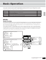
Basic Operation.................................................................................................................. Page 27
This section introduces you to the basic operating conventions of this instrument, such as editing values and changing
settings.
Quick Guide ........................................................................................................................ Page 40
In this tutorial section, you will take a guided tour through the various functions of this instrument, and get some
hands-on experience in playing and using it.
Basic Structure ................................................................................................................. Page 128
This section provides a detailed overview of all of the main functions and features of this instrument, and shows how
they fit together.
Reference ......................................................................................................................... Page 151
The MO encyclopedia. This section explains all parameters, settings, functions, features, modes and operations in full detail.
Appendix .......................................................................................................................... Page 219
This section contains detailed information on the instrument, including the Specifications and an Alert Message List.
Troubleshooting............................................................................................................... Page 227
If this instrument does not function as expected or you have some problem with the sound or operation, refer to this
section before calling your Yamaha dealer or service center. Most common problems and their solutions are covered
here in a very simple and easy-to-understand way.
Data List (separate booklet)
This contains various important lists such as the Voice List, Preset Pattern Phrase List, Effect List, MIDI Data Format,
and MIDI Implementation Chart.
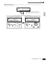
Throughout this manual, arrows are used in the instructions, indicating in shorthand the process of calling up certain
displays and functions. The example instructions below indicate to 1) press the [VOICE] button, 2) select a Normal
Voice, 3) press the [EDIT] button, 4) select an Element, 5) press the [F1] OSC button, and 6) press the [SF2] OUTPUT
button.
[VOICE] ➞ Normal Voice selection ➞ [EDIT] ➞ Element selection ➞ [F1] OSC ➞ [SF2] OUTPUT
n
8
When a confirmation message (page 37) or Control Function window (page 51) is shown in the display, press the [EXIT] button to exit from
that condition, then execute the instructions as in the above example. Likewise, press the [DAW REMOTE] button to exit from the Remote
Control mode, then execute the instructions as in the above example when the MO is in the Remote Control mode.
Owner’s Manual
Application Index
Application Index
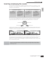
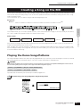
Listening to the MO
•
•
•
•
Listening to the Demo Song/Pattern .............................................................................................................................................................. Page 73
Listening to Song Chain playback.................................................................................................................................................................. Page 95
Listening to Pattern Chain playback .............................................................................................................................................................. Page 84
Listening to Arpeggio playback...................................................................................................................................................................... Page 48
Playing the keyboard
•
•
•
•
•
•
Selecting a Voice and playing the keyboard ..................................................................................Pages 40 (Voice mode), 76 (Song/Pattern mode)
Selecting a Performance and playing the keyboard ..................................................................................................................................... Page 44
Using the instrument as a Master Keyboard ............................................................................................................................................... Page 122
Sounding the metronome..................................... [SONG] or [PATTERN] → [UTILITY] → [F3] SEQ → [SF1] CLICK → Mode = all .......... Page 206
Splitting the keyboard—Setting upper and lower ranges for the Voices ................................Pages 47 (Performance mode), 125 (Master mode)
Layering two Voices (or Parts) together.....................................................................................Pages 46 (Performance mode), 125 (Master mode)
Selecting programs and making settings on the MO
• Selecting a Voice ..............................................................................................................................Pages 40 (Voice mode), 76 (Song/Pattern mode)
Using the Category Search function .............................................................................................................................................................. Page 42
• Selecting a Performance ................................................................................................................................................................................. Page 44
• Selecting a Song .............................................................................................................................................................................................. Page 74
• Selecting a Pattern ........................................................................................................................................................................................... Page 75
Selecting a Section .......................................................................................................................................................................................... Page 75
Selecting a Phrase and assigning it to a Pattern track................................................................................................................................. Page 78
•
•
•
•
•
Selecting a Mixing template for a Song/Pattern ............................................................................................................................................ Page 77
Selecting a Master.......................................................................................................................................................................................... Page 122
Selecting an Arpeggio type....................................................................................... Pages 48 (Voice/Performance mode), 80 (Song/Pattern mode)
Selecting a Filter type .................................................................................................................................................................................... Page 170
Selecting an Effect type
Selecting a Reverb type/Chorus type/Insertion type
[VOICE] → Voice selection → [F3] EFFECT ................................................................................................................................................... Page 151
[PERFORM] → Performance selection → [F3] EFFECT → [SF1] CONNECT ................................................................................................ Page 171
[SONG] or [PATTERN] → Song/Pattern selection→ [MIXING] → [F3] EFFECT → [SF1] CONNECT ............................................................. Page 189
Selecting a Master Effect type
[VOICE] → [UTILITY] → [F3] VOICE → [SF2] MEF ........................................................................................................................................ Page 206
[PERFORM] → Performance selection → [EDIT] → [COMMON] → [F2] OUT/MEF → [SF3] MEF ................................................................ Page 172
[SONG] or [PATTERN] → Song/Pattern selection→ [MIXING] → [EDIT] → [COMMON] → [F2] MEQ/MEF → [SF2] MEF ........................... Page 190
Selecting a Master EQ type
[VOICE] → [UTILITY] → [F3] VOICE → [SF1] MEQ ....................................................................................................................................... Page 206
[PERFORM] → Performance selection→ [EDIT] → [COMMON] → [F2] OUT/MEF → [SF2] MEQ ................................................................ Page 172
[SONG] or [PATTERN] → Song/Pattern selection→ [MIXING] → [EDIT] → [COMMON] → [F2] OUT/MEF → [SF1] MEQ ........................... Page 190
Using controllers
•
•
•
•
Understanding the organization and structure of the controllers ........................................................................................................Pages 50, 69
Assigning functions to the controllers for each Voice (Controller Set) ...................................................................................................... Page 70
Assigning Control Change numbers to each controller............................................................................................................................... Page 72
Setting the Pitch Bend Range
[VOICE] → Voice selection→ [EDIT] → [COMMON] → [F1] GENERAL → [SF5] OTHER → PB Upper/PB Lower ....................................... Page 154
[SONG] or [PATTERN] → Song/Pattern selection→ [MIXING] → [EDIT] → Part selection→ [F1] VOICE → [SF5] OTHER → PB Upper/PB Lower ........ Page 191
•
•
•
•
•
Checking the currently assigned parameters for knob control .......... Pages 56 (Voice mode), 65 (Performance mode), 96 (Song/Pattern mode)
Checking the currently assigned parameters for Control sliders control .................................................................................................. Page 52
Starting/stopping a Song or Pattern by pressing a Footswitch ............................... [UTILITY] → [F4] CTL ASN → [SF3] FT SW .......... Page 209
Changing a Voice or a Performance by pressing a Footswitch ................................ [UTILITY] → [F4] CTL ASN → [SF3] FT SW .......... Page 209
Turning Arpeggio playback on or off by pressing a Footswitch............................... [UTILITY] → [F4] CTL ASN → [SF3] FT SW .......... Page 209
• Keeping the effect of a controller (Modulation Wheel, etc.) the same, even when changing Voices
[UTILITY] → [F1] GENERAL → [SF4] OTHER → CtrlReset = hold ................................................................................................................. Page 206
Owner’s Manual
9
Application Index
Sounding only the specified Part or Voice
• Turning each element on or off in the Voice Edit mode.................................................................................................................................Page 55
• Determining whether each Element is used or not in the Voice Edit mode
[VOICE] → [EDIT] → Element selection → [F1] OSC → [SF1] WAVE → ElementSw = on/off ........................................................................Page 158
• Determining whether each Part is used or not in the Performance mode
[PERFORM] → Performance selection→ [EDIT] → Part selection → [F1] VOICE → [SF1] VOICE → PartSw = on/off ..................................Page 174
• Turning each track (Part) of a Song/Pattern on or off....................................................................................................................................Page 75
• Turning off or muting playback of a Song/Pattern Part, by setting the receive channel to off
[SONG] or [PATTERN] → Song/Pattern selection → [MIXING] → [EDIT] → part selection → [F1] VOICE → [SF2] MODE → ReceiveCh ............Page 191
Adjusting the volume or output level
• Overall
Adjusting the Master Volume output................................................................................................................ [MASTER VOLUME] .............Page 16
Adjusting the entire volume of the instrument’s internal tone generator block ..... [UTILITY] → [F1] GENERAL → [SF1] TG → Volume ...........Page 205
Adjusting the output gain of each Output connector........................................................................... [UTILITY] → [F2] OUTPUT ...........Page 206
• In the Voice mode
Adjusting the volume balance of the Elements of a Normal Voice with the Control sliders
[VOICE] → Normal Voice selection → [EDIT] → Element selection→ [F4] AMP → [SF1] LVL/PAN → Level ...................................................Page 56
Adjusting the entire volume for the selected Voice (common to all Elements/keys)
[VOICE] → Voice selection→ [EDIT] → [COMMON] → [F2] OUTPUT → Volume ..........................................................................................Page 154
• In the Performance mode
Adjusting the volume balance of the Parts of an edited Performance with the Control sliders
[PERFORM] → Performance selection → [EDIT] → Part selection → [F2] OUTPUT → [SF1] VOL/PAN → Volume .......................................Page 65
Adjusting the entire volume for the selected Performance (common to all Parts)
[PERFORM]→ Performance selection → [EDIT] → [COMMON] → [F2] OUT/MEQ → [SF1] OUT → Volume ...............................................Page 172
• In the Song mode/Pattern mode
Adjusting the volume balance of the Parts of an edited Song with the Control sliders
[SONG] or [PATTERN] → Song/Pattern selection → [MIXING] → Part Selection → [F1] VOL/PAN → VOLUME .............................................Page 97
Creating Data
• Creating a Voice
Creating a Normal Voice in the Voice Edit mode ............................................................................................................................................Page 53
Creating a Drum Voice in the Voice Edit mode ...............................................................................................................................................Page 57
Creating a Mixing Voice especially for a Song or Pattern .............................................................................................................................Page 78
• Creating a Performance....................................................................................................................................................................................Page 63
• Creating a Song
Recording your keyboard performance to a Song track (Realtime Recording) ..........................................................................................Page 88
Recording over (replacing) existing material in a Song track—Punch-in Recording
[SONG] → [REC] → [F1] SETUP → Type = punch ...........................................................................................................................................Page 88
Recording additional material to an existing Song track (without erasing previous material)—Overdub Recording
[SONG] → [REC] → [F1] SETUP → Type = overdub ........................................................................................................................................Page 80
Sounding the metronome during recording............................ [SONG] → [UTILITY] → [F3] SEQ → [SF1] CLICK → Mode = rec ...........Page 206
Recording a Song by using a Performance ...................................................................................................................................................Page 89
Using the Step Recording function ..................................................................... [SONG] → [REC] → [F1] SETUP → Type = step .............Page 80
Editing MIDI events for each track of an already-recorded Song ....................................... [SONG] → [EDIT] → Track selection .............Page 90
Inserting Tempo change information in the middle of the Song ............................................. [SONG] → [EDIT] → [F4] TR SEL .............Page 88
Inserting Voice change information
[SONG] → [EDIT] → Track selection → Inserting a Bank Select MSB/LSB and Program Change ................................................................Page 182
Editing Song Mixing settings, such as the volume of each Part ................................................................. [SONG] → [MIXING] .............Page 93
Using convenient “Jobs,” such as Copy, Clear, Quantize ....................................................... [SONG] → [JOB] → Job selection .............Page 91
• Creating a Pattern
Assigning a Preset Phrase to each track of a Pattern (Patch function).......................................................................................................Page 78
Recording your keyboard performance to a Pattern track to create a Phrase............................................................................................Page 82
Recording a newly found Arpeggio rhythm pattern to a Pattern track ........................................................................................................Page 80
Sounding the metronome during recording....................... [PATTERN] → [UTILITY] → [F3] SEQ → [SF1] CLICK → Mode = rec ...........Page 206
Using the Step Recording function ................................................................ [PATTERN] → [REC] → [F1] SETUP → Type = step .............Page 83
Editing MIDI events for each track of an already-recorded Pattern................................ [PATTERN] → [EDIT] → Track selection .............Page 90
Editing Pattern Mixing settings, such as the volume of each Part.......................................................... [PATTERN] → [MIXING] .............Page 93
Using convenient “Jobs,” such as Copy, Clear, Quantize .................................................. [PATTERN] → [JOB] → Job selection .............Page 91
Programming a sequence of a Section to create a Pattern Chain ...................................................... [PATTERN] → [F6] CHAIN .............Page 85
Converting a Pattern Chain to Song data ....................... [PATTERN] → Pattern selection → [F6] CHAIN → [EDIT] → [F3] SONG .............Page 86
• Creating a Master............................................................................................................................................................................................Page 122
• Creating an Arpeggio ......................................................................................................................................................................................Page 97
10
Owner’s Manual
Application Index
Storing/Saving the created data
• Storing an edited Voice to internal memory (Flash ROM) and saving all the Voices in internal memory to a USB storage device .......................... Page 60
• Storing an edited Performance to internal memory (Flash ROM) and saving all the Performances in internal memory to
a USB storage device ...................................................................................................................................................................................... Page 66
• Saving the Song/Pattern data
Storing Song Mixing/Pattern Mixing settings to internal memory (DRAM) .........................................................................................Pages 77, 94
Storing the entire Song/Pattern data to a USB storage device.................................................................................................................... Page 98
• Storing Mixing settings to internal memory (Flash ROM) as a template .................................................................................................... Page 94
• Storing an edited Master to internal memory (Flash ROM) and saving all the Masters on internal memory to
a USB storage device ................................................................................................................................................................................... Page 123
• Saving all Arpeggios in internal memory (Flash ROM) to a USB storage device .................................................................................... Page 214
Naming your created data .............................................................................................................................................................. Page 38
Recovering lost data
Comparing the Voice, Performance, Song, or Pattern before editing with the just-edited one (Compare function) .............................. Page 36
Recalling an edited, but not-stored Voice, Performance, Song or Pattern (when another Voice has been selected)
—Recall function.............................................................................................................................................................................................. Page 37
• Song/Pattern
Canceling the changes made in the recent session such as Recording and Job to restore the data to its previous status
[SONG] or [PATTERN] → [JOB] → [F1] UNDO ................................................................................................................................................ Page 93
Initializing
•
•
•
•
•
•
•
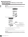
Resetting the User Memory to the Initial Factory Settings .......................................................................................................................... Page 26
Formatting a USB storage device................................................................................................................................................................. Page 213
Initializing the edited Voice................................................................................................................ [VOICE] → [JOB] → [F1] INIT .......... Page 168
Initializing the edited Performance............................................................................................. [PERFORM] → [JOB] → [F1] INIT .......... Page 177
Initializing the edited Master ......................................................................................................... [MASTER] → [JOB] → [F1] INIT .......... Page 218
Initializing the edited Song Mixing settings ................................................................ [SONG] → [MIXING] → [JOB] → [F1] INIT .......... Page 192
Initializing the edited Pattern Mixing settings ........................................................ [PATTERN] → [MIXING] → [JOB] → [F1] INIT .......... Page 202
Pitch related settings (Tune, Note Shift, etc.)
• Overall
Changing the octave setting of the keyboard ............................................ [UTILITY] → [F1] GENERAL → [SF2] KBD → Octave
Shifting the note up or down on the keyboard ..................................... [UTILITY] → [F1] GENERAL → [SF2] KBD → Transpose
Shifting the note up or down in the tone generator block ........................ [UTILITY] → [F1] GENERAL → [SF1] TG → NoteShift
Adjusting the tuning to other instruments ........................................................ [UTILITY] → [F1] GENERAL → [SF1] TG → Tune
............ Page 29
............ Page 29
.......... Page 205
.......... Page 205
• In the Voice mode
Setting the tuning system for the voice
[VOICE] → Voice selection → [EDIT] → [COMMON] → [F1] GENERAL → [SF2] PLY MODE → M.TuningNo. ....................................... Page 169
Adjusting the pitch for each Element of the edited Voice in semitones
[VOICE] → Voice selection→ [EDIT] → Element selection→ [F2] PITCH → [SF1] TUNE → Coarse ............................................................. Page 159
Finely adjusting the pitch for each Element of the edited Voice
[VOICE] → Voice selection→ [EDIT] → Element selection→ [F2] PITCH → [SF1] TUNE → Fine ................................................................. Page 159
Setting the all notes (keys) to the same pitch
[VOICE] → Voice selection→ [EDIT] → Element selection→ [F2] PITCH → [SF4] KEY FLW → PitchSens = 0 ............................................ Page 159
• In the Performance mode
Shifting the note up or down for each Part of the edited Performance
[PERFORM] → Performance selection → [EDIT] → Part selection → [F4] TONE → [SF1] TUNE → NoteShift ............................................ Page 176
Finely adjusting the pitch for each Part of the edited Performance
[PERFORM] → Performance selection → [EDIT] → Part selection → [F4] TONE → [SF1] TUNE → Detune ................................................ Page 176
• In the Song mode/Pattern mode
Shifting the note up or down for each Part of the current Song/Pattern
[SONG] or [PATTERN] → Song/Pattern selection → [MIXING] → [EDIT] → Part selection → [F4] TONE→ [SF1] TUNE → NoteShift ......... Page 191
Finely adjusting the pitch for each Part of the current Song/Pattern
[SONG] or [PATTERN] → Song/Pattern selection→ [MIXING] → [EDIT] → Part selection → [F4] TONE → [SF1] TUNE → Detune ....... Page 191
• In the Master mode
Shifting the keyboard octave up or down for each zone of the edited Master
[MASTER] → Master selection → [F2] MEMORY → ZoneSwitch = on → [EDIT] → Zone selection → [F2] NOTE → Octave ...................... Page 216
Finely adjusting the keyboard pitch for each zone of the edited Master
[MASTER] → Master selection→ [F2] MEMORY → ZoneSwitch = on → [EDIT] → Zone selection → [F2] NOTE → Transpose .................. Page 216
Owner’s Manual
11
Application Index
Connecting to a computer/external MIDI instrument
• Determining which connector (MIDI, USB TO HOST) is used for MIDI input/output
[UTILITY] → [F5] MIDI → [SF4] OTHER → MIDI IN/OUT ................................................................................................................................Page 210
• Using the sounds of the MO for Song playback from a MIDI sequencer...................................................................................................Page 110
• Setting whether or not Bulk Dump data can be received
[UTILITY] → [F5] MIDI → [SF2] SWITCH → RcvBulk = on/protect .................................................................................................................Page 209
• Sounding only the external MIDI tone generator and turning the internal tone generator off
[UTILITY] → [F5] MIDI → [SF2] SWITCH → LocalCtrl = off ............................................................................................................................Page 209
• Synchronizing with an external MIDI instrument/computer
Using the MO as a MIDI master
[UTILITY] → [F5] MIDI → [SF3] SYNC → MIDI Sync = internal, ClockOut = on, Seqctrl = out ...................................................................Page 210
Using the MO as a MIDI slave
[UTILITY] → [F5] MIDI → [SF3] SYNC → MIDI Sync = MIDI, ClockOut = off, Seqctrl = in .............................................................................Page 210
Using the MO as a MTC slave
[UTILITY] → [F5] MIDI → [SF3] SYNC → MIDI Sync = MTC, ClockOut = off, Seqctrl = in .............................................................................Page 210
• Disabling synchronization with the external MIDI instrument/computer
Maintaining normal playback on an external MIDI sequencer, even when starting/stopping Song/Pattern playback on the MO
[UTILITY] → [F5] MIDI → [SF3] SYNC → MIDI Sync = internal, Seqctrl = off ................................................................................... ...........Page 210
Maintaining normal Song/Pattern playback on the MO, even when starting/stopping playback on an external MIDI sequencer
[UTILITY] → [F5] MIDI → [SF3] SYNC → Seqctrl = off ...................................................................................................................... ...........Page 210
• Synchronizing the LFO wave speed of the Voice with an external MIDI instrument/computer
[UTILITY] → [F5] MIDI → [SF3] SYNC → MIDI Sync = MIDI ..........................................................................................................................Page 210
[VOICE] → Normal Voice selection → [EDIT] → [COMMON] → [F5] LFO → [SF1] WAVE → TempoSync = on ...........................................Page 156
• Setting which MIDI events will be transmitted or recognized via the MIDI and USB TO HOST connectors
[SONG] or [PATTERN] → [UTILITY] → [F3] SEQ → [SF2] FILTER ..................................................................................................................Page 207
• Setting the MIDI transmit channel
Setting the MIDI transmit channel of the keyboard in the Voice mode/Performance mode
[UTILITY] → [F5] MIDI → [SF1] CH → KBDTransCh .......................................................................................................................................Page 209
Setting the MIDI transmit channel and port for each track of a Song/Pattern
[SONG] or [PATTERN] → Song/Pattern selection → [F3] TRACK → [SF1] CHANNEL ...................................................................................Page 178
Setting the MIDI transmit channel of Arpeggio playback
[UTILITY] → [F3] VOICE → [SF3] ARP CH → TransmitCh ..............................................................................................................................Page 206
• Setting the MIDI receive channel
Setting the MIDI receive channel of the keyboard in the Voice mode/Performance mode
[UTILITY] → [F5] MIDI → [SF1] CH → BasicRcvCh ........................................................................................................................................Page 209
Setting the MIDI receive channel for each part of a Song/Pattern
[SONG] or [PATTERN] → Song/Pattern selection → [MIXING] → [EDIT] → Part selection→ [F1] VOICE → [SF2] MODE → ReceiveCh .............Page 191
• Setting parameters for Program Change transmission/recognition
Enabling or disabling the sending of Bank Select and Program Change messages, when selecting a Voice or Performance
[UTILITY] → [F5] MIDI → [SF2] SWITCH → BankSel, PgmChange ................................................................................................................Page 209
Enabling or disabling selection of MO Voices/Performances from an external MIDI device
[UTILITY] → [F5] MIDI → [SF2] SWITCH → BankSel, PgmChange ................................................................................................................Page 209
[SONG] or [PATTERN] → Song/Pattern selection → [MIXING] → [EDIT] → Part selection→ [F5] RCV SW → BankSel, PgmChange .........Page 192
Setting related parameters so that the MIDI messages produced by the Song/Pattern playback will not be transmitted via MIDI
[SONG] or [PATTERN] → [UTILITY] → [F3] SEQ → [SF2] FILTER ...............................................................................................................Page 207
• Setting whether each track playback sounds the internal tone generator or an external tone generator
[SONG] or [PATTERN] → Song/Pattern selection → [F3] TRACK → [SF2] OUT SW .....................................................................................Page 179
Other tips
• Loading the specified file on the USB storage device automatically when the power is turned on.......................................................Page 102
• Setting the Mode set automatically when the power is turned on
[UTILITY] → [F1] GENERAL → [SF4] OTHER → PowerOnMode ....................................................................................................................Page 206
12
Owner’s Manual
Table of Contents
Table of Contents
Introduction ...............................................................6
Accessories...............................................................6
Main Features............................................................7
How to use this manual .............................................8
Application Index ................................................... 9
The Controls & Connectors
14
Front Panel ..............................................................14
Rear Panel...............................................................18
Setting up and Playing
20
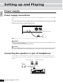
Power supply...........................................................20
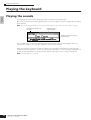
Playing the keyboard ..............................................22
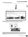
Modes .....................................................................24
Basic instructions ....................................................25
Resetting the User Memory to the Initial Factory
Settings ...................................................................26
Basic Operation
27
Modes .....................................................................27
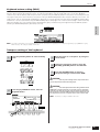
About data storage to USB storage devices ..........30
Functions and Sub-Functions .................................33
Selecting a Program................................................33
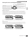
Moving the Cursor and Setting Parameters ............35
About the editing functions .....................................36
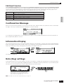
Confirmation Message ............................................37
Information Display .................................................37
Note (Key) settings..................................................37
Naming....................................................................38
Quick Guide
Connecting the MO to external devices ...........103
Connections ......................................................... 103
Using as a Multi-timbral Tone Generator for your
DAW/sequencer ................................................... 110
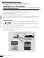
Using the MO with computer software ................. 112
Creating Your Original Program Set
(Master mode) .....................................................122
Basic Structure
128
Internal Structure (System Overview) ................... 128
Internal Memory and File Management................ 148
Reference
151
Voice mode........................................................... 151
Performance mode ............................................... 171
Song mode ........................................................... 178
Pattern mode ........................................................ 196
Mixing Voice mode ............................................... 203
Utility mode........................................................... 205
File mode .............................................................. 211
Master mode......................................................... 215
Appendix
219
Information Displays ............................................. 219
Display Messages ................................................ 221
About MIDI............................................................ 223
Troubleshooting.................................................... 227
Specifications ....................................................... 231
Index..................................................................... 232
40
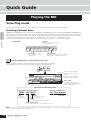
Playing the MO ..................................................... 40
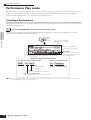
Voice Play mode .....................................................40
Performance Play mode..........................................44
Using the Arpeggio feature.....................................48
Using the Controllers on the MO.............................50
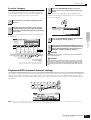
Editing a Program ................................................ 53
Editing a Voice ........................................................53
Editing a Performance.............................................63
Using the Controllers—Advanced Course ........ 69
Controllers supported by the MO............................69
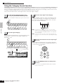
Creating a Song on the MO ................................. 73
Playing the Demo Songs/Patterns...........................73
Creating a Pattern ...................................................76
Creating a Song ......................................................87
Owner’s Manual
13
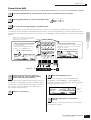
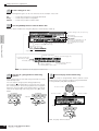
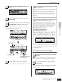
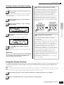
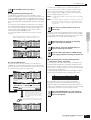
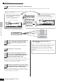
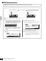
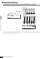
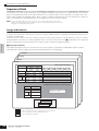
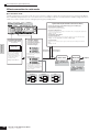
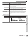
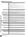
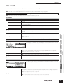
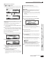
Front Panel
The Controls & Connectors
Front Panel
MO8
3
6
4
PHONES
OUTPUT
L MONO
FOOT
CONTROLLER
DIGITAL OUT
R
FOOT
SWITCH
MIDI
OUT
IN
TO HOST
THRU
TO DEVICE
DAW REMOTE PAGE SELECT
USB
ASSIGN A
PAN SEND
ASSIGN
TONE
ASSIGN B
PAN
REVERB
CUTOFF
RESONANCE
SWING
GATE TIME
LOW
LOW MID
ASSIGN 1
ASSIGN 2
CHORUS
TEMPO
ATTACK
RELEASE
VELOCITY UNIT MULTIPLY
HIGH MID
HIGH
9
ARP FX
MEF
)
EFFECT ARPEGGIO
EQ
MASTER
EFFECT
ARPEGGIO
ON OFF
EFFECT
BYPASS
7
SCENE
SEQ TRANSPORT
LOCATE
5
1
2
!
F1
REC
MASTER
VOLUME
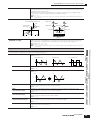
A-1 B-1 C0 D0 E0 F0 G0 A0 B0 C1
ZONE 1
ZONE 2
ZONE 3
$ ^
ZONE 4
C2
C3
1
n
When [UTILITY] → [F1] GENERAL → [SF2] KBD → Octave is set to “0,” each key corresponds to the note name shown in the
illustrations. Refer to this illustration when setting a note name of a parameter like Note Limit.
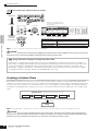
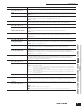
MO6
PHONES
OUTPUT
L MONO
6
DIGITAL OUT
R
FOOT
CONTROLLER
FOOT
SWITCH
IN
MIDI
OUT
TO HOST
THRU
TO DEVICE
USB
TONE
ASSIGN 2
ASSIGN B
ASSIGN 1
PAN
REVERB
CHORUS
TEMPO
CUTOFF
RESONANCE
ATTACK
RELEASE
SWING
GATE TIME
LOW
LOW MID
ASSIGN A
ASSIGN
HIGH MID
HIGH
MEF
9
)
MASTER
EFFECT
2
MODE
EFFECT
BYPASS
PERFORM
MASTER
SONG
PATTERN
MIXING
FAV
DEC NO
INC YES
SCENE
SEQ TRANSPORT
DAW
REMOTE
LOCATE
OCTAVE
5
4
1
ZONE 1
ZONE 2
ZONE 3
7
SF2
SF3
SF4
SF5
F2
F3
F4
F5
F6
EXIT
ENTER
EDIT
EXECUTE
COMPARE
JOB
ZONE 4
!
UTILITY
DEMO
F1
C1 D1 E1 F1 G1 A1 B1 C2
$ ^
%
& ™
C3
1
When both of the [OCTAVE] buttons are turned off, each key corresponds to the note name shown in the
illustrations. Refer to this illustration when setting parameters having note name values, such as Note Limit.
Owner’s Manual
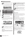
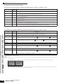
FILE
INFORMATION
2
REC
UP
MASTER
VOLUME
14
VOICE
ARPEGGIO
ON OFF
SF1
n
( 8@
EFFECT ARPEGGIO
EQ
3
*
VELOCITY UNIT MULTIPLY
ARP FX
DOWN
º
#
DAW REMOTE PAGE SELECT
PAN SEND
¡
£
C4
CO
STORE
SCENE STORE
SET LOCATE
The Controls
& Connectors
Front Panel
DC IN
º
#
*
( 8@
¶
STANDBY
ON
¢
CATEGORY
SEARCH
MODE
VOICE
SONG
DEC NO
SF1
SF2
SF3
SF4
SF5
PERFORM
MASTER
PATTERN
F2
F3
F4
F5
PRE 1
PRE 2
PRE 3
PRE 4
GM
–
A. PIANO
KEYBOARD
ORGAN
GUITAR
PLUCKED
BASS
STRINGS
BRASS
REED PIPE
A
B
C
D
E
F
G
H
SYN LEAD
SYN PAD
CHOIR
SYN COMP
1
2
3
MIXING
USER 2
SECTION
DAW
REMOTE
FILE
ENTER
EDIT
JOB
EXECUTE
COMPARE
UTILITY
DRUM
CHROMATIC
PERCUSSION PERCUSSION
SE
MUSICAL FX
COMBI
4
5
6
7
8
TRACK
SELECT
12
13
14
15
16
MUTE
%
& ™
C4
9
11
ª
‚
§
C5
DC IN
10
SOLO
SCENE STORE
SET LOCATE
¡ £
ELEMENT PERF. PART ZONE
COMMON
STORE
•
∞
INC YES
EXIT
F6
¶
USER 1
INFORMATION
DEMO
F1
DRUM
KITS
FAVORITES
C6
C7
STANDBY
ON
¢
CATEGORY
SEARCH
DRUM
KITS
PRE 1
PRE 2
PRE 3
PRE 4
GM
–
FAVORITES
A. PIANO
KEYBOARD
ORGAN
GUITAR
PLUCKED
BASS
STRINGS
BRASS
REED PIPE
A
B
C
D
E
F
G
H
SYN LEAD
SYN PAD
CHOIR
SYN COMP
1
2
3
USER 1
CHROMATIC
DRUM
PERCUSSION PERCUSSION
USER 2
SECTION
∞
SE
MUSICAL FX
COMBI
4
5
6
7
8
TRACK
SELECT
12
13
14
15
16
MUTE
ELEMENT PERF. PART ZONE
COMMON
9
10
11
SOLO
E
•
ª
‚
§
C5
C6
Owner’s Manual
15
Front Panel
The Controls
& Connectors
1 Keyboard
n
The MO6 features a 61-key keyboard, while the MO8 has
88 keys.
All are equipped with an initial touch feature. With initial
touch, the instrument senses how strongly or softly you
play the keys, and uses that playing strength to affect the
sound in various ways, depending on the selected voice.
2 OCTAVE [UP] and [DOWN] buttons
Page 29
Use these buttons to change the note range of the
keyboard. To restore the normal octave setting, press both
buttons simultaneously.
n
Because of its extended keyboard, the MO8 does not have
OCTAVE buttons.
3 Pitch bend wheel
Page 50
Controls the pitch bend effect. You can also assign other
functions to this controller.
4 Modulation wheel
Page 50
Controls the modulation effect. You can also assign other
functions to this controller.
) [ARPEGGIO ON/OFF] button
Adjusts the volume of the overall sound, as output from the
rear-panel OUTPUT L/MONO and R jacks as well as the
PHONES jack.
6 Four Knob Control Function buttons and four
Knobs
Page 51
These four highly versatile knobs let you adjust various
aspects or parameters of the current Voice. Use the Knob
Control Function buttons to change the parameter set for
the knobs. The corresponding LED lights to indicate which
group of parameters are active.
7 Control slider
Page 52
These sliders control the volume of four elements which
make up a Normal Voice in the Voice mode, the volume of
four parts in the Performance mode, the volume of four
parts including the current part in the Song mode/Pattern
mode, and the volume of four zones in the Master mode.
n
If all of the Control sliders are set to the minimum, you may not
hear any sound from the instrument, even when playing the
keyboard or a Song/Pattern. If this is the case, raise all the
sliders to a suitable level.
n
The [MASTER VOLUME] slider adjusts the output level from
this instrument. On the other hand, the Control sliders adjust
the MIDI volume value for the corresponding element or part.
8 DAW REMOTE button
Page 113
The Remote mode lets you control sequencer software on
your computer from the panel controls of the instrument.
Turn the [DAW REMOTE] button on to enter the Remote
mode.
9 [MASTER EFFECT] button and
[EFFECT BYPASS] button
! SEQ TRANSPORT buttons
These buttons control recording and playback of the Song/
Pattern sequence data.
[
Owner’s Manual
] (Top) button
Instantly returns to the beginning of the current Song or
Pattern (i.e., the first beat of the first measure).
[
] (Reverse) button
Press briefly to move back one measure at a time, or hold
to continuously rewind.
] (Forward) button
Press briefly to move forward one measure at a time, or
hold to continuously fast-forward.
[REC] (Record) button
Press this to enable recording (Song or Pattern phrase).
(The indicator lights.)
[
] (Stop) button
Press to stop recording or playback.
[
] (Play) button
Press to start playback from the current point in the Song
or Pattern. During recording and playback, the indicator
flashes at the current tempo.
@ MODE buttons
Page 24
These buttons select the operating modes (e.g., Voice
mode).
# LCD Display
The large backlit LCD displays the parameters and values
related to the currently selected operation or mode.
$ LCD Contrast Control
Page 21
Use this control to set the LCD display for optimum
legibility.
% [F1] – [F6] (Function) buttons
Page 33
These buttons located directly below the LCD display call
up the corresponding functions indicated in the display. In
the display hierarchy, these functions [F] rank just below
the modes.
^ [SF1] – [SF5] (Sub Function) buttons Page 33
Page 140
The extensive effect section of the instrument provides
Insertion effects (three sets, with two effect units per set),
System effects (Reverb and Chorus), and Master effects.
The effects can be applied to the keyboard-played voices
and to Song/Pattern playback. These buttons enable you
to turn the corresponding Effect blocks (as printed on the
panel) on or off with a single touch.
16
Page 48
Press this button to enable or disable playback of the
Arpeggio for each Voice, Performance, Song, or Pattern. If
the Arpeggio Switch of the selected part is set to off in the
Performance/Song/Pattern mode, however, pressing this
button has no effect.
[
5 [MASTER VOLUME] slider
From the following display, you can select the specific
effect(s) to be bypassed when using the [EFFECT
BYPASS] button. [UTILITY] → [F1] GENERAL → [SF3] EF
BYPS display
These buttons located directly below the LCD display call
up the corresponding sub functions indicated in the
display. In the display hierarchy, these sub functions [SF]
rank just below the functions [F].
These buttons can be also used to store/recall the
Arpeggio type in each Play mode and Song/Pattern
Record mode. They can be also used to store/recall the
Song Scene (page 89) in the Song Play and Song Record
modes.
Front Panel
Page 37
For calling up a special “help” feature that shows
information about the currently selected mode. You can go
back to the previous display by pressing this button again
or pressing any other button.
Depending on the selected display, this button may be
used to call up a window for inputting characters, for
inputting numbers, for selecting note lengths, or for
selecting keys or note names (page 35).
* Data dial
Page 35
For editing the currently selected parameter. To increase
the value, turn the dial right (clockwise); to decrease the
value, turn the dial left (counter-clockwise). If a parameter
with a wide value range is selected, you can change the
value in broader strokes by quickly turning the dial.
( [INC/YES] button
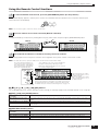
§ Number [1] – [16] buttons
Use of these buttons differs depending on the on/off status
of the [TRACK SELECT] and [MUTE] buttons.
Functions of the Number [1] – [16] buttons
When [TRACK
SELECT] is on
Voice Edit mode
Performance
Play mode
Performance
Edit mode
You can also use the [INC/YES] and [DEC/NO] buttons to
quickly move through parameter values in 10-unit jumps,
especially those with large ranges. Simply hold down one of
the buttons (of the direction you want to jump), and
simultaneously press the other. For example, to jump in the
positive direction, hold down the [INC/YES] button and press
[DEC/NO].
¡ Cursor buttons
Page 35
The cursor buttons move the “cursor” around the LCD
display screen, highlighting and selecting the various
parameters.
™ [EXIT] button
Page 28
The menus and displays of this synthesizer are organized
according to a hierarchical structure.
Press this button to exit from the current display and return
to the previous level in the hierarchy.
£ [ENTER] button
Use this button to execute a Job or a Store operation. Also
use this button to actually enter a number when selecting a
Memory or Bank for Voice or Performance. In the File
mode, use this button to go to the next lowest level in the
selected directory.
¢ Bank buttons
Page 40
Each button selects a Voice or Performance Bank.
When the [CATEGORY SEARCH] button is turned on,
these buttons can be used to select the desired category
(printed below each button). When the [SECTION] button
is turned on in the Pattern mode, these buttons are used to
select the desired section.
∞ Group [A] – [H] buttons
Page 41
Each button selects a Voice or Performance Group.
When the [CATEGORY SEARCH] button is turned on,
these buttons can be used to select the desired category
(printed below each button). When the [SECTION] button
is turned on in the Pattern mode, these buttons are used to
select the desired section.
Element selection (1 – 4) and
Element Mute setting (9 – 12)
Voice selection,
according to Groups
A–H
—
Performance or
Voice selection
Performance part
(if cursor is located
Mute setting
at Voice name),
Performance part (1 – 4)
according to Groups
selection (1 – 4)
A–H
Keyboard
transmit channel
setting
Master Play
mode
—
Master selection,
according to Groups
A–H
Master Edit
mode
Zone selection
(1 – 4)
—
—
Song/Pattern
Play mode
Song/Pattern
track selection
For decreasing the value of the currently selected
parameter. Also use it to cancel a Job or a Store operation.
n
—
When both
[TRACK SELECT]
[MUTE] are off
Keyboard transmit
channel setting
(when memorizing
the Voice mode or
Performance
mode to the
current Master) or
Song/Pattern track
selection (when
memorizing the
Song mode or
Pattern mode to
the current
Master)
Page 35
Page 35
When [MUTE]
is on
Keyboard
Voice Play mode transmit channel
setting
For increasing the value of the currently selected
parameter. Also use it to actually execute a Job or a Store
operation.
º [DEC/NO] button
The Controls
& Connectors
& [INFORMATION] button
Song/Pattern
track Mute
setting
Song/Pattern
Mixing mode
Song/Pattern
selection, according
Song/Pattern part Song/Pattern part to Groups A – H
selection
Mute setting
Mixing Voice
Edit mode
Element selection (1 – 4) and
Element Mute setting (9 – 12)
¶ [CATEGORY SEARCH] button
—
Page 42
When this button is turned on, the Bank buttons and the
Group buttons can be used to select the Voice/
Performance category.
• [SECTION] button
Page 73
When this button is turned on in the Pattern mode, the
Group [A] – [H] buttons can be used to select Pattern
Sections A – H and the [PRE1] – [–] buttons of the Bank
buttons can be used to select Pattern Sections I – P.
ª [TRACK SELECT] button
Page 76
Turning this button on in the Song/Pattern mode enables
the Number [1] – [16] buttons for selecting corresponding
Song/Pattern tracks. The on/off status of this button affects
the Number [1] – [16] buttons in different ways, depending
on the selected mode. (See § “Number [1] – [16] buttons”
above.)
‚ [MUTE] button
Page 74
Turning this button on in the Song/Pattern mode enables
the Number [1] – [16] buttons for muting corresponding
Song/Pattern tracks.
Press one of the Number [1] – [16] buttons while holding
this button to solo the corresponding track of the current
selected Song/Pattern.
The on/off status of this button affects the Number [1] –
[16] buttons in different ways, depending on the selected
mode. (See § “Number [1] – [16] buttons” above.)
Owner’s Manual
17
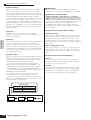
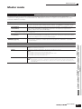
Rear Panel
The Controls
& Connectors
Rear Panel
MO8
DC IN
STANDBY
ON
1
2
3
MO6
STANDBY
ON
DC IN
THRU
TO DEVICE
MIDI
OUT
IN
TO HOST
USB
1
2
3
4
1 STANDBY/ON switch
Page 20
Press to turn power ON or OFF.
2 DC IN terminal
Page 20
Connect the AC adaptor to this terminal.
WARNING
Do not attempt to use an AC adaptor other than the Yamaha PA-5D or an
equivalent recommended by Yamaha. The use of an incompatible
adaptor may cause irreparable damage to the MO, and may even pose a
serious shock hazard!
ALWAYS UNPLUG THE AC ADAPTOR FROM THE AC POWER OUTLET
WHEN THE MO IS NOT IN USE.
3 Cable clip
Wrap the DC output cable of the adaptor around the cable
clip (as shown below) to prevent accidental unplugging of
the cable during operation.
5
4 USB connectors
This instrument is equipped with two types of USB
connectors on the rear panel—USB TO HOST and USB TO
DEVICE. The USB TO HOST connector is used to connect
this instrument to the computer via the USB cable. The
USB connection between the instrument and the computer
can only be used for transfer of MIDI data. No audio data
can be transferred via USB. The USB TO DEVICE
connector is used to connect this instrument to a USB
storage device (hard disk drive, CD-ROM drive, MO drive,
flash disk, etc.) via the USB cable. This lets you save the
data created on this instrument to the external USB
storage device and load the data from the external USB
storage device to the instrument. Save/Load operations
can be performed in the File mode.
n
For details about USB, see page 31.
USB
USB is an abbreviation for Universal Serial Bus. It is a serial
interface for connecting a computer with peripheral
devices, and enables much faster data transfer compared
to conventional serial port connections.
STANDBY
ON
DC IN
5 MIDI IN/OUT/THRU connectors
Page 104
MIDI IN is for receiving control or performance data from
another MIDI device, such as an external sequencer.
MIDI THRU is simply for redirecting any received MIDI
data (via MIDI IN) to connected devices, allowing
convenient chaining of additional MIDI instruments.
MIDI OUT is for transmitting all control, performance
and playback data from the MO to another MIDI device,
such as an external sequencer.
18
Owner’s Manual
4
5
MIDI
USB
TO DEVICE
6
TO HOST
THRU
OUT
7
IN
OUTPUT
R
)
FOOT
CONTROLLER
DIGITAL OUT
OUTPUT
R
6
7
)
FOOT
CONTROLLER
FOOT
SWITCH
DIGITAL OUT
FOOT
SWITCH
The Controls
& Connectors
Rear Panel
PHONES
L MONO
8
9
PHONES
L MONO
8
9
6 FOOT SWITCH jack
Page 69
For connection of optional FC4 or FC5 Footswitch.
7 FOOT CONTROLLER jack
Page 69
For connection of an optional foot controller (FC7, etc.).
The FOOT CONTROLLER jack lets you continuously
control one of various different assignable functions—such
as volume, tone, pitch, or other aspects of the sound.
8 OUTPUT L/MONO and R jacks
Page 20
Line level audio signals are output via these phone jacks.
For monophonic output, use just the L/MONO jack.
9 PHONES jack
Page 20
For connection to a pair of stereo headphones.
) DIGITAL OUT connector
Page 103
Use this connector to input or output digital signals over
coaxial (RCA-pin) cable. The format is S/PDIF, normally
used for CD and DAT players. The digital signal output is
44.1kHz/24-bit.
Owner’s Manual
19
Power supply
Setting up and Playing
Setting up
and Playing
Power supply
Power supply connections
Before you connect the power adapter, make sure that the MO [STANDBY/ON] switch is set to STANDBY
(Off).
1
2
Connect the plug of the power adapter PA-5D to the DC IN terminal on the rear panel of the MO.
Plug in the AC cable to an appropriate AC outlet.
Rear panel
DC IN
STANDBY
ON
2 To electrical outlet
1
Power adapter
PA-5D
AC cable
n Follow this procedure in reverse order to disconnect the power adapter.
WARNING
• Be sure to use the included adapter. Using an AC adapter other than the PA-5D may cause damage to the MO, and may even
pose a serious electrical shock hazard.
• Connect the adapter to an AC outlet of the specified voltage.
CAUTION
Even when the [STANDBY/ON] switch is in the STANDBY position, a small amount of electricity is still flowing to the unit. When
you do not plan to use the MO for an extended period of time, be sure to unplug the AC power adapter from the AC outlet.
Connecting the speakers or pair of headphones
Since the MO has no built-in speakers, you will need to monitor the sound of the instrument by using
external equipment. Connect a set of headphones, powered speakers, or other playback equipment as
required.
Powered speaker (Left)
Powered speaker (Right)
Headphones
OUTPUT L/MONO
OUTPUT R
PHONES
MO
20
Owner’s Manual
Power supply
Turning the power on
Setting up
and Playing
Make sure the volume settings of the MO and external devices are turned down to the minimum.
MASTER
VOLUME
Turn the power on by pressing the [STANDBY/ON] switch on the MO rear panel, then turn the power on the
amplifiers.
Connecting MIDI devices or a Mixer
Make sure that all volume settings are turned down all the way to the minimum. Then turn on the every
device in your setup in the order of MIDI masters (controllers), MIDI slaves (receivers), then audio
equipment (mixers, amplifiers, speakers, etc.).
When powering down the setup, first turn down the volume of each audio device, then switch off each
device in the reverse order (first audio devices, then MIDI).
1
2
3
POWER
ON!!
MIDI master
MO (MIDI slave)
Audio equipment
(first mixer, then amplifier)
Adjusting the sound and the display contrast
Adjust the volume levels of the MO and the connected amplifier/speaker system. If the display is not easily
visible, use the Contrast control to adjust for optimum visibility.
Adjust the volume with the
MASTER VOLUME slider.
Adjust the display contrast
with the Contrast control.
SF1
F1
MASTER
VOLUME
Contrast control
Now that you’ve set up the MO properly, you’re ready to begin playing it.
n
When you are ready to turn off the MO, make sure to switch off the power of the external device (or lower its volume)
before switching off the MO.
Owner’s Manual
21
Playing the keyboard
Playing the keyboard
Setting up
and Playing
Playing the sounds
Try playing some of the realistic and dynamic MO sounds from the keyboard now.
When you turn the power on following the directions in “Power supply connections” (page 20), the display
below appears.
n In the default settings, the Master mode is selected. For details about the modes, refer to the section “Modes” on page 24.
Indicates that the Master mode
is selected.
Indicates the type of
selected program.
Indicates the name and number of
selected program.
In this condition you can play the keyboard and hear the sounds of the selected program. When the
instrument is turned on, the “The Core” program is automatically called up.
Notice the indication “Performance:USR1:017 (B01)” at the top right of the display. This indicates that
Performance 017 in User bank 1 is currently selected. A “Performance” is one of the types of programs of
the MO. As described below, the instrument also features other types: Voices, Songs, and Patterns.
n For details about Banks, see page 40.
22
Owner’s Manual
Playing the keyboard
Selecting and playing the sounds
For playing the keyboard
Voice
This program contains a
basic instrument sound,
such as a piano, guitar,
bass guitar, drum kit, etc.
Setting up
and Playing
The MO provides three different types of programs for playing the sounds: Voices, Performances, Songs,
and Patterns. The basic difference among these programs is in their use—for playing the keyboard, or for
creating music with multiple parts.
For creating music of multiple parts
Performance
This program allows you to
combine several Voices
together—either in a richly
textured layer, or separately
(as in different sections of
the keyboard) for playing
several different parts
simultaneously.
Song
This is a program consisting
of recorded keyboard
performance data, and/or
patterns created in the
Pattern mode.
Pattern
This is a program that
consists of individually
created phrases or patterns
of short duration (generally
two or four measures), used
for certain parts in a song—
such as the intro, main
melody or chorus.
You can choose from 128 different Voices, Performances, Songs, and Patterns in the Master mode. To
change the desired Master number, use the [INC/ YES] button, [DEC/NO] button, or the Data dial.
Decreases number
DEC/NO
Decreases number
Increases number
INC / YES
Increases number
Change the Master number, and then try playing the various Voices or Performance types. When a Voice is
assigned to the selected Master number, “Voice” will appear at the top of the display. When a Performance
is assigned, “Performance” will appear in the display.
n You can also choose some Songs and Patterns in the Master mode. For details about Songs and Patterns, see page 73.
As you play the various Voices and Performances, notice the differences between them—especially how
some Performances sound exceptionally rich and more complex than Voices. Note also how many
Performances use automatic rhythms and Arpeggios—along with keyboard split sounds—to let you sound
like an entire band all by yourself!
Here, we’ve introduced the operations in the Master mode that is called up first when turning the power on.
The MO has other modes of operation as well. In the next section, we’ll explain about the modes of the MO
and how they are used.
Owner’s Manual
23
Modes
Modes
There are several operation modes in the MO, and
they can be selected by using the 12 mode buttons.
MODE
VOICE
Setting up
and Playing
1
PERFORM
2
SONG
4
3
PATTERN
MIXING
5
DAW
REMOTE
7
MASTER
6
FILE
UTILITY
8
9
DEMO
EDIT
JOB
)
!
COMPARE
@
SCENE STORE
SET LOCATE
1 Playing the keyboard
using a Voice
2 Playing the keyboard
using multiple Voices
3 Creating original
program sets
Voice mode
Performance mode
Master mode
[VOICE] button
[PERFORM] button
The MO has a wealth of high-quality, dynamic
sounds—also referred to as “Voices.”
You can play these Voices—one Voice at a time—from
the keyboard in the Voice mode.
The MO also lets you create your own original Voices.
In the Performance mode, you can play several Voices
together in a layer, or play different Voices from
separate ranges of the keyboard. You can also trigger
automatic rhythms and Arpeggios, over which you can
play melody, chord or bass lines of your own. Each of
these combinations of Voices is called a
“Performance.” This mode lets you create richly
textured, layered sounds or play two or more different
parts simultaneously—for example, piano and bass
guitar—and is particularly useful when performing
solo.
[MASTER] button
The Master mode can be used in two ways:
• Storing your favorite settings that you often use in
the Voice, Performance, Song, or Pattern mode, and
instantly recall the mode and custom settings
together in a single button press.
• Dividing the keyboard into four separate sections—
just as if you were playing four different MIDI
keyboards.
4 Creating original songs
5 Creating rhythm patterns
6 Creating mixing settings
Song mode
Pattern mode
[SONG] button
[PATTERN] button
Song Mixing or
Pattern Mixing mode
The Song mode lets you create your own original
songs by recording your performance using Voices
created in the Voice mode or by combining preset
rhythmic Patterns.
7 Controlling your computer
DAW from the MO
Remote Control mode
[DAW REMOTE] button
The Remote Control mode lets you control your
computer’s sequencer software or DAW (digital audio
workstation) by using the buttons or controllers on the
MO.
In this mode, you can separately create the various
“building blocks” of a song—rhythms and patterns for
the intro, verse, main melody, chorus, etc.
8 Backing up data
File mode
[FILE] button
The File mode lets you save your MO data to a USB
storage device, and allows you to load data from the
USB device to the MO.
[MIXING] button
Here, you can make various mixing settings, adjusting
the level balance among the parts of the Song or
Pattern, as well as each pan position and the effects
applied to the Song/Pattern.
9 Setting the system
parameters
Utility mode
[UTILITY] button
The Utility mode lets you set parameters that apply to
the entire system of the MO.
These parameter settings are applied to all Voices,
Performances, Songs and Patterns.
) Setting the parameters
for each mode
! Tools for organizing
your data
@ Storing programs
to the MO
Edit mode
JOB mode
Store mode
[EDIT] button
[JOB] button
The Edit mode lets you set parameters that apply to
each Voice, Performance, Song or Pattern.
24
STORE
Owner’s Manual
This mode provides various operations and functions
(called “jobs”) that help in organizing and controlling
your important data, including initializing the settings
and copying data.
[STORE] button
In this mode, you can store your edited programs to
the internal memory of the MO. Keep in mind,
however, that certain data, such as Songs and
Patterns, are deleted when the power is turned off. For
this reason, you should also store this important data
to a USB memory device in the File mode.
Basic instructions
Basic instructions
Voices—the basic building blocks of the MO
Selecting a preset Voice
Page 40
Creating a new Voice
Page 53
Setting up
and Playing
Voices—created in the Voice mode—are the basic sonic building blocks for the other modes of the MO. The
Performance, Song, and Pattern programs are made up of different Voices, used together for specific
performance or song recording. The MO features an exceptionally wide variety of preset Voices for playing in
virtually any musical style. Try searching through the Voices to find your favorites.
Once you’ve explored them and feel comfortable with them, try branching out creatively and use the editing
features to make your own original Voices.
Combine several Voices to create a Performance
To play several different Voices together simultaneously, select a Performance. The MO features 256 specially
programmed Performances for playing in a variety of music styles.
Selecting a preset Performance
Page 44
Creating a new Performance
Page 63
Create a Song by recording your performance or combining some rhythm patterns
You can create your own Songs by using the built-in sequencer functions of the MO. The MO provides two
different ways for creating Songs: 1) recording a Song conventionally from beginning to end, and 2) creating
separate short sections (or “Patterns”), each several measures in length, and combining/repeating them to
construct an entire Song.
Creating a Song
Page 87
Creating a Pattern
Page 76
Master mode—Create a master keyboard setup or instantly call up your desired
programs
The Master mode lets you register your favorite Voices, Performances, Songs, and Patterns together into easy-to
select Master programs. No matter what mode is used—Voice, Performance, Song, or Pattern—you can have it
instantly and automatically selected when you call up the appropriate Master.
The Master mode can also be used to divide the keyboard into four sections—each with its own Voice—just as if
you were playing four different MIDI keyboards.
Making Master mode settings
Page 122
Convenient remote control of your computer software
The panel of the MO also serves as a convenient control surface for your computer music system. Use the
buttons and sliders to control the audio mixer and sequencer transport functions in your MIDI/audio software.
This highly intuitive approach gives you hands-on control over your virtual studio—a level of control that a
computer keyboard and mouse can’t match. These features are available for any computer sequence software
and Multi Part Editor software (page 112) compatible with the Remote Control function.
Remote-controlling the software
Page 113
Global settings and data backup
While the Voice, Performance, Song, and Pattern modes provide controls for using and editing the programs of
the MO, the Utility mode is the place where you make overall settings for the instrument—for example, adjusting
the transpose and fine tuning controls, or switching between MIDI and USB operation. You can also archive your
important MO data to a USB storage device for safe-keeping.
Making global system settings
Page 205
Backing up important data
Page 211
This concludes our short guide to the basic operations and functions of the MO. Enjoy the dynamic,
authentic sounds of the instrument as you continue to play it and create music on it. Make sure to check
out the references above and go on to explore some of the other exciting and powerful features of the MO.
Owner’s Manual
25
Resetting the User Memory to the Initial Factory Settings
Resetting the User Memory to the Initial
Factory Settings
The original factory setting of this synthesizer’s User Memory can be restored as follows.
Setting up
and Playing
WARNING
When the factory settings are restored, all the Voice, Performance, Song, Pattern, and system setting in the Utility mode you
created will be erased. Be sure to save all important data to USB storage device before executing this procedure (pages 60, 66
and 98).
1
Press the [UTILITY] button to enter the Utility mode.
MODE
VOICE
PERFORM
MASTER
SONG
PATTERN
MIXING
DAW
REMOTE
FILE
UTILITY
DEMO
EDIT
JOB
STORE
COMPARE
2
SCENE STORE
SET LOCATE
Press the [JOB] button to enter the Utility Job mode.
MODE
VOICE
PERFORM
MASTER
SONG
PATTERN
MIXING
DAW
REMOTE
FILE
UTILITY
DEMO
EDIT
JOB
STORE
n
COMPARE
3
SCENE STORE
SET LOCATE
When the checkbox of “PowerOn Auto” is on (checked)
and you execute the Factory Set Job, Factory Set will be
executed automatically when the power is turned on. In
general, this box should be off (unchecked).
If PowerOn Auto is checked here and you want to
execute the Factory Set Job, first uncheck the box, then
execute the Job.
Press the [ENTER] button. (The display prompts you for confirmation.)
To cancel the Job, press the [DEC/NO] button.
4
Press the [INC/YES] button to execute the Job.
After the Job has been completed, a “Completed” message appears and operation returns to the original display.
CAUTION
For Factory Set operations that take longer to process, you will see the message “Executing…” or “Please Keep Power On!”
during processing. Do not switch the power off while this message is on the display. Turning the power off in this state results in
loss of all user data and may cause the system to freeze. This means that this synthesizer may not be able to start up properly,
even when turning the power on next time.
26
Owner’s Manual
Modes
Basic Operation
In this section, we’ll take a look at the fundamental operating conventions of the MO. Here, you’ll learn the basics—how to
select modes, call up the various functions, change settings, and edit parameter values. Before reading further, familiarize
yourself with the basic terms used with the MO in the chart below.
Description
Page
Musical instrument voices
Performance
A program in which multiple Voices are combined in a layer
40
44
Song
Music data consisting of MIDI events
73
Pattern
Rhythm pattern data consisting of MIDI events used for looped playback
73
Master
A program which lets you register the settings in each mode—Voice, Performance, Song, and Pattern
122
File
A collection of settings for storing and managing your created data
211
Basic Operation
Term
Voice
Modes
Mode Structure
This synthesizer is organized into various modes, each covering a different set of operations and functions. Keep in mind
that there are two basic types of modes, depending on the status of the tone generator block. The first type includes the
Voice and Performance modes, and the internal tone generator is used in single timbre operation—meaning that only one
Voice, or one channel of MIDI data is used.
The second type includes the Song and Pattern modes, and the internal tone generator is used in multi-timbral operation—
meaning that several Voices, or multiple MIDI channels are used. In addition to the above, there are three special modes.
The Master mode lets you memorize your desired settings in each mode (Voice/Performance/Song/Pattern) and recall them
instantly anytime you need them with a single button. The File mode lets you manage your created data, while the Utility
mode provides controls related to the overall operation of the instrument.
Keyboard Playback mode (single timbre tone generator)
Voice mode
Voice Play mode
Voice Edit mode
Voice Job mode
Voice Store mode
VOICE
PERFORM
Performance mode
Performance Play mode
Performance Edit mode
Performance Job mode
Performance Store mode
MODE
VOICE
SONG
PERFORM
MASTER
MIXING
PATTERN
Keyboard Playback mode (multi-timbral tone generator)
SONG
Song mode
Song Play mode
Song Record mode
Song Edit mode
Song Job mode
Song Mixing mode
Song Mixing Edit mode
Song Mixing Job mode
Song Mixing Store mode
PATTERN
Pattern mode
Pattern Play mode
Pattern Record mode
Pattern Edit mode
Pattern Job mode
Pattern Mixing mode
Pattern Mixing Edit mode
Pattern Mixing Job mode
Pattern Mixing Store mode
Master mode
Master Play mode
Master Edit mode
Master Job mode
Master Store mode
MASTER
FILE
File mode
DAW
REMOTE
(Mixing Voice mode)
Mixing Voice Edit mode
Mixing Voice Job mode
Mixing Voice Store mode
UTILITY
FILE
UTILITY
Utility mode
Utility Job mode
MIXING
DEMO
EDIT
COMPARE
JOB
STORE
SCENE STORE
SET LOCATE
Owner’s Manual
27
Modes
Mode table
The functions of each mode and how to enter each mode are as follows:
Mode
Voice mode
Basic Operation
Performance mode
Song mode
Pattern mode
(Mixing Voice mode)
Utility mode
Master mode
File mode
Voice Play mode
Function
Playing a Voice
How to enter the mode
[VOICE]
Voice Edit mode
Editing/Creating a Voice
[VOICE] → [EDIT]
Voice Job mode
Initializing a Voice, etc.
[VOICE] → [JOB]
Voice Store mode
Storing a Voice to internal memory
[VOICE] → [STORE]
Performance Play mode
Playing a Performance
[PERFORM]
Performance Edit mode
Editing/Creating a Performance
[PERFORM] → [EDIT]
Performance Job mode
Initializing a Performance, etc.
[PERFORM] → [JOB]
Performance Store mode
Storing a Performance to internal memory
[PERFORM] → [STORE]
Song Play mode
Playing a Song
[SONG]
Song Record mode
Recording a Song
[SONG] → [REC]
Song Edit mode
Editing a Song MIDI events
[SONG] → [EDIT]
Song Job mode
Converting and transforming Song data
[SONG] → [JOB]
Song Mixing mode
Setting tone generator parameters
[SONG] → [MIXING]
Song Mixing Edit mode
Setting tone generator parameters in detail
[SONG] → [MIXING] → [EDIT]
Song Mixing Job mode
Initializing a Song Mixing, etc.
[SONG] → [MIXING] → [JOB]
Song Mixing Store mode
Storing a Song Mixing internal memory
[SONG] → [MIXING] → [STORE]
Pattern Play mode
Playing a Pattern
[PATTERN]
Pattern Record mode
Recording a Pattern
[PATTERN] → [REC]
Pattern Edit mode
Editing a Pattern MIDI events
[PATTERN] → [EDIT]
Pattern Job mode
Converting and transforming Pattern data
[PATTERN] → [JOB]
Pattern Mixing mode
Setting tone generator parameters
[PATTERN] → [MIXING]
Pattern Mixing Edit mode
Setting tone generator parameters in detail
[PATTERN] → [MIXING] → [EDIT]
Pattern Mixing Job mode
Initializing a Pattern Mixing, etc.
[PATTERN] → [MIXING] → [JOB]
Pattern Mixing Store mode
Storing a Pattern Mixing internal memory
[PATTERN] → [MIXING] → [STORE]
Mixing Voice Edit mode
Editing/Creating a Voice dedicated for Song/Pattern
[SONG] or [PATTERN] → [MIXING] → [F5]
VCE ED
Mixing Voice Job mode
Initializing a Mixing Voice, etc.
[SONG] or [PATTERN] → [MIXING] → [F5]
VCE ED → [JOB]
Mixing Voice Store mode
Storing a Mixing Voice to internal memory
[SONG] or [PATTERN] → [MIXING] → [F5]
VCE ED → [STORE]
Utility mode
Setting System related parameters
[UTILITY]
Utility Job mode
Resetting the User Memory to the Initial Factory
Settings
[UTILITY] → [JOB]
Master Play mode
Playing a Master
[MASTER]
Master Edit mode
Editing/Creating a Master
[MASTER] → [EDIT]
Master Job mode
Initializing a Master, etc.
[MASTER] → [JOB]
Master Store mode
Storing a Master to internal memory
[MASTER] → [STORE]
File mode
Managing Files and Folders (Directories)
[FILE]
■ How to leave the current display
For most operations or displays (except for the File mode, Song/Pattern Record mode, and Remote Control mode), pressing
the [EXIT] button will let you leave the current display and return you to the previous one. You can return back to any of the
modes—Voice Play, Performance Play, Song Play, Pattern Play, and Master Play—by pressing the [EXIT] button several
times in the respective mode.
DEC/NO
INC / YES
EXIT
ENTER
EXECUTE
28
Owner’s Manual
Modes
Keyboard octave setting (MO6)
Basic Operation
Sometimes when playing a voice, you may wish to play in a lower or higher pitch range. For example, you may want to shift
the pitch down lower to get extra bass notes, or shift up to get higher notes for leads and solos. The Octave Up/Down
controls let you do this quickly and easily. Each time you press the [OCTAVE UP] button on the panel, the overall pitch of the
voice goes up by one octave. Likewise, each press of the [OCTAVE DOWN] button takes the pitch down by one octave. The
range is from -3 to +3, with 0 being standard pitch. When this is set to Octave Up, the lamp of the [OCTAVE UP] button lights,
and when it is set to Octave Down, the [OCTAVE DOWN] button’s lamp lights. The current octave setting is shown at the top
right of the display. You can instantly restore standard pitch (0) by simultaneously pressing both the [OCTAVE UP] button
and the [OCTAVE DOWN] button (both lamps turn off).
OCTAVE
DOWN
n
UP
The Octave setting made here is automatically reflected in the identical Octave parameter in the Utility mode ([UTILITY] → [F1] GENERAL → [SF2]
KBD → Octave). This setting is available in all modes.
Transpose setting of the keyboard
You can set the amount in semitones by which the range of the keyboard is shifted up or down as well as the octave setting.
1
Press the [UTILITY] button to enter the Utility
mode.
3
Move the cursor to “Transpose” by using the
Cursor button.
4
Change the Transpose value by using the
[INC/YES], [DEC/NO] buttons and data dial.
5
Press the [STORE] button to store the
Transpose setting to internal Flash ROM.
MODE
VOICE
PERFORM
SONG
MIXING
PATTERN
DAW
REMOTE
MASTER
FILE
UTILITY
CAUTION
DEMO
EDIT
JOB
COMPARE
STORE
Make sure to execute step 5. The settings made in step 4 will be lost if
you turn the power off without executing step 5.
SCENE STORE
SET LOCATE
CAUTION
2
Press the [F1] GENERAL button, then the
[SF2] KBD button.
Never attempt to turn off the power while data is being written to Flash
ROM (while a “Please keep power on” message is shown). Turning the
power off in this state may not only cause the system to freeze (due to
data corruption in the Flash ROM) and prevent normal startup the next
time the power is turned on, it may also result in loss of all user data.
n
The transpose setting is available in all modes.
SCENE
SF1
F1
SF2
F2
SF3
F3
SF4
F4
SF5
F5
INFORMATION
F6
Owner’s Manual
29
About data storage to USB storage devices
About data storage to USB storage devices
As you make music with this instrument, you’ll create a wide variety of data—such as custom Voice data (including Voices,
Performances, etc.), and MIDI sequence data (Songs, Patterns, Arpeggios).
Naturally, you’ll want to store this data for safekeeping and future use, and for this reason the instrument is equipped with a
USB TO DEVICE connector—letting you save your data to a convenient USB storage device. To recall the data, use the Load
function. (Save and Load operations are done in the File mode; see page 211.)
Keep in mind that certain types of data are lost when you turn off the power and should be properly saved.
Basic Operation
USB storage device (page 31)
USB TO DEVICE connector
MO
Data lost and data retained when power is turned off
The chart below lists the data types you can create on the instrument and the internal memory locations to which they are
stored, permanently or temporarily.
CAUTION
Make sure to save any data remaining in DRAM to a USB storage device before turning off the power, other wise the data will be lost.
Data types
Page
Mode in which data is created
Internal memory types to which data is stored
Voice
53
Voice mode
Flash ROM
DRAM → Lost when power is turned off.
Mixing Voice
78
Mixing Voice mode
Performance
63
Performance mode
Flash ROM
Song*
87
Song mode
DRAM → Lost when power is turned off.
Song Chain
95
Song Chain mode
DRAM → Lost when power is turned off.
Pattern*
76
Pattern mode
DRAM → Lost when power is turned off.
Pattern Chain
84
Pattern Chain mode
DRAM → Lost when power is turned off.
Phrase (Pattern)
79
Pattern mode
DRAM → Lost when power is turned off.
Arpeggio
97
Song mode, Pattern mode
Flash ROM
Master
122
Master mode
Flash ROM
Mixing Template**
77
Song Mixing mode, Pattern Mixing mode
Flash ROM
System settings
205
Utility mode
Flash ROM
* Includes the Mixing settings (pages 137, 138)
** Song Mixing/Pattern Mixing can be stored as Song/Pattern data and as a Mixing Template (which are not associated with a specific Song/Pattern).
n
30
For details about the data types you can create on this instrument, the internal memory locations to which they are stored, and file types when saving
the created data to the USB storage device, refer to “Memory Structure” on page 149.
Owner’s Manual
About data storage to USB storage devices
Using USB storage devices
When using USB storage devices, make sure to connect them to the USB TO DEVICE connector, and follow the important
precautions below.
■ Compatible USB devices
The MO does not necessarily support all commercially
available USB storage devices. Yamaha cannot guarantee
operation of USB storage devices that you purchase.
Before purchasing USB storage devices, please consult
your Yamaha dealer, or an authorized Yamaha distributor
(see list at end of the Owner’s Manual) for advice, or see
the following website:
http://www.yamahasynth.com/
n
Although CD-R/W drives can be used to load data to the
instrument, they cannot be used for saving data. However, you can
transfer data to a computer and save data to a CD using the CD-R/
W drive on the computer.
■ Formatting USB storage media
When a USB storage device is connected or media is
inserted, a “USB device unformatted.” message may
appear in the LCD display, indicating that the device or
media must be formatted for use. Execute the Format
operation in the File mode (page 211).
USB connector types
There are two different types of USB connectors, and
the rear panel of the instrument features both. Take
care not to confuse the two.
Basic Operation
Connect only a USB storage device (such as hard disk,
CDROM, flash disk and other drives) to the USB TO
DEVICE connector. Other devices such as a computer
keyboard or mouse cannot be used.
Both bus-powered (powered by the host device) or selfpowered (battery or external power supply) types can be
used.
■ USB TO HOST connector
This type is used to connect the instrument to a computer,
and allows you to transfer MIDI data between the devices.
The USB connection between the instrument and the
computer can only be used for transfer of MIDI data. Unlike
MIDI, USB can handle multiple ports via a single cable.
USB cables may have different connectors on each end: the
A type and the B type. Connect the A type to your computer
and the B type to the USB TO HOST connector.
■ USB TO DEVICE connector
This type is used to connect the instrument to a USB storage
device, and allows you to save data you’ve created to the
connected device, as well as load data from the connected
device. This lets you save the data created on this instrument
to the external USB storage device and load the data from
the external USB storage device to the instrument. Save and
Load operations are executed in the File mode (page 211).
USB cables may have different connectors on each end: the
A type and the B type. Connect the A type to the USB TO
DEVICE connector and the B type to the USB storage
device.
MIDI data transfer
Precautions when using the USB TO DEVICE
connector
Saving/loading data in
the File mode (page 211)
Connecting to
a computer
CAUTION
Never turn the USB device’s power on/off and never plug/unplug
the USB cable when the connected USB storage device is the self
powered type. Doing so may result in the operation of the
synthesizer “freezing” or hanging up.
While the instrument is accessing data (such as in the Save,
Load and Delete operations in the File mode), do NOT unplug the
USB cable, do NOT remove the media from the device, and do
NOT turn the power off to either device. Doing so may corrupt the
data on either or both devices.
B type
USB TO HOST
connector
■ To protect your data (write-protect):
To prevent important data from being inadvertently erased,
apply the write-protect provided with each storage device
or media.
If you are saving data to the USB storage device, make
sure to disable or remove write-protect.
A type
USB TO DEVICE
connector
Connecting to a USB
storage device (hard
disk, CD-ROM, flash
disk and other
devices)
MO
n
The computer cannot access the USB storage device
connected to the USB TO DEVICE connector on the MO,
even if connecting as shown above. Only from the File mode
on the instrument itself can you access the data on the USB
storage device connected to the USB TO DEVICE
connector.
n
Though the MO supports only up to the USB 1.1 standard,
USB 2.0 storage devices can be connected and used with
the instrument. However, note that the transfer speed
complies to USB 1.1.
Owner’s Manual
31
About data storage to USB storage devices
TIP Backing up your data to a computer
■ Backing up MO data to a computer
■ Loading data from a computer to the MO
Once you’ve saved data to a USB storage device, you
can copy the data to the hard disk of your computer,
then archive and organize the files as desired. Simply
reconnect the device as shown below.
Data and files contained on the hard disk of a computer
can be loaded to the MO by copying them first to the
storage media, then transferring them to the instrument.
In this way, you can use data created on the computer
or another instrument with the MO. For example, you
can load Standard MIDI files to the instrument as Song/
Pattern data, or import files created on the MOTIF ES.
Basic Operation
Saving created data to the USB storage device in the
File mode (page 211)
Copying the files of the hard disk of the computer to
the USB storage device
USB storage device
Computer
USB TO DEVICE connector
USB storage device
Computer
MO
Disconnect the USB storage
device from the synthesizer
and connect it to the computer
MO
Disconnect the USB storage
device from the computer and
connect it to the synthesizer
Backing up data to a computer and organizing files/
folders
Loading files on the USB storage device to the
synthesizer in the File mode (page 211)
USB storage device
Computer
USB storage device
Computer
USB TO DEVICE connector
MO
MO
32
Owner’s Manual
Functions and Sub-Functions
Functions and Sub-Functions
Each mode described above contains various displays, with various functions and parameters. To navigate your way
through these displays and select a desired function, use the [F1] – [F6] buttons and the [SF1] – [SF5] buttons. When you
select a mode, the available displays or menus appear directly above the buttons at the bottom of the display (as shown
below).
Basic Operation
Using the Function buttons [F1] – [F6]
These functions can be selected
via the corresponding button
([F1] – [F6]).
SCENE
SF1
F1
SF2
F2
SF3
F3
SF4
F4
SF5
F5
INFORMATION
F6
In this example, press the [F5]
button to go to the LFO display.
Depending on the currently selected mode, up to six functions are available and can be called up with the [F1] – [F6]
buttons. Keep in mind that the available functions differ depending on the selected mode.
Using the Sub-Function buttons [SF1] – [SF5]
These functions can be selected
via the corresponding button
([SF1] – [SF5]).
SCENE
SF1
F1
SF2
F2
SF3
F3
SF4
F4
SF5
F5
INFORMATION
F6
In this example, press the [SF5]
button to go to the OTHER display.
Depending on the currently selected mode, up to five functions (sub-functions) are available and can be called up with the
[SF1] – [SF5] buttons. Keep in mind that the available functions differ depending on the selected mode. (Some displays may
not have any sub-functions for these buttons.)
Selecting a Program
In order to play the MO you’ll need to call up one of its programs, i.e., a Voice, Performance, Song, Pattern, or Master. These
programs can be selected in each Play mode via the same procedure.
■ Using the [INC/YES], [DEC/NO] buttons and the data dial
The [INC/YES] and [DEC/NO] buttons let you step up or down through the program numbers in any of the Play modes
(Voice, Performance, Song, Pattern, and Master).
Rotating the data dial to the right (clockwise) increases the program number, while rotating it to the left (counter-clockwise)
decreases it. This control works in the same way as the [INC/YES] and [DEC/NO] buttons, but lets you scroll through the
programs more quickly.
Decreases number
DEC/NO
Decreases number
Increases number
INC / YES
Increases number
Owner’s Manual
33
Selecting a Program
■ Using the Group buttons and Number buttons
As shown below, you can select a program number by pressing any of the Group [A] – [H] buttons and pressing any of the
Number [1] – [16] buttons.
The explanations here apply when these
button indicators are off.
Basic Operation
PRE 1
PRE 2
PRE 3
PRE 4
USER 1
A. PIANO
KEYBOARD
ORGAN
GUITAR
PLUCKED
BASS
A
B
C
D
E
SYN LEAD
SYN PAD
CHOIR
SYN COMP
1
2
3
GM
–
STRINGS
BRASS
REED PIPE
F
G
H
USER 2
CHROMATIC
DRUM
PERCUSSION PERCUSSION
SECTION
SE
MUSICAL FX
COMBI
4
5
6
7
8
TRACK
SELECT
12
13
14
15
16
MUTE
ELEMENT PERF. PART ZONE
9
10
11
SOLO
n
The convenient Category Search function (page 42) lets you easily locate and select the Voices you want by type.
The Voice program numbers and the corresponding Group/Numbers are listed below.
34
Program
Number
Group
Number
Program
Number
Group
Number
Program
Number
Group
Number
Program
Number
Group
Number
001
002
003
004
005
006
007
008
009
010
011
012
013
014
015
016
017
018
019
020
021
022
023
024
025
026
027
028
029
030
031
032
A
A
A
A
A
A
A
A
A
A
A
A
A
A
A
A
B
B
B
B
B
B
B
B
B
B
B
B
B
B
B
B
1
2
3
4
5
6
7
8
9
10
11
12
13
14
15
16
1
2
3
4
5
6
7
8
9
10
11
12
13
14
15
16
033
034
035
036
037
038
039
040
041
042
043
044
045
046
047
048
049
050
051
052
053
054
055
056
057
058
059
060
061
062
063
064
C
C
C
C
C
C
C
C
C
C
C
C
C
C
C
C
D
D
D
D
D
D
D
D
D
D
D
D
D
D
D
D
1
2
3
4
5
6
7
8
9
10
11
12
13
14
15
16
1
2
3
4
5
6
7
8
9
10
11
12
13
14
15
16
065
066
067
068
069
070
071
072
073
074
075
076
077
078
079
080
081
082
083
084
085
086
087
088
089
090
091
092
093
094
095
096
E
E
E
E
E
E
E
E
E
E
E
E
E
E
E
E
F
F
F
F
F
F
F
F
F
F
F
F
F
F
F
F
1
2
3
4
5
6
7
8
9
10
11
12
13
14
15
16
1
2
3
4
5
6
7
8
9
10
11
12
13
14
15
16
097
098
099
100
101
102
103
104
105
106
107
108
109
110
111
112
113
114
115
116
117
118
119
120
121
122
123
124
125
126
127
128
G
G
G
G
G
G
G
G
G
G
G
G
G
G
G
G
H
H
H
H
H
H
H
H
H
H
H
H
H
H
H
H
1
2
3
4
5
6
7
8
9
10
11
12
13
14
15
16
1
2
3
4
5
6
7
8
9
10
11
12
13
14
15
16
n
When selecting a Voice and Pattern, it is necessary to press one of the Bank buttons before pressing the Group and Number buttons.
n
The amount of numbers differ depending on the program. For example, while the selected number range of the Normal Voice, Performance, and
Master is 001 – 128, the selected number range of the Song and Pattern is 001 – 064.
Owner’s Manual
Moving the Cursor and Setting Parameters
Moving the Cursor and Setting Parameters
Changing (editing) parameter values
Rotating the data dial to the right (clockwise) increases
the value, while rotating it to the left (counter-clockwise)
decreases it.
Moving the cursor
DEC/NO
INC / YES
EXIT
ENTER
For parameters with large value ranges, you can
increase the value by 10 by simultaneously holding
down the [INC/YES] button and pressing the [DEC/NO]
button. To decrease by 10, do the opposite;
simultaneously hold down the [DEC/NO] button and
press the [INC/YES] button.
Basic Operation
Use these four buttons to navigate the display, moving
the cursor around the various selectable items and
parameters in the screen. When selected, the relevant
item is highlighted (the cursor appears as a dark block
with inverse characters). You can change the value of
the item (parameter) at which the cursor is located by
using the data dial, [INC/YES] and [DEC/NO] buttons.
EXECUTE
■ Inputting a number directly
For parameters having large value ranges (such as the Song measure), you can also enter the value directly, using the
buttons below the LCD display as a numeric keypad. When the cursor is located on such a parameter, the [NUM] icon
appears at the lower right corner of the LCD display indicating that you can call up the number input window by pressing the
[INFORMATION] button. From this window, you can input a number directly by pressing the [F1] – [F6] buttons and the [SF1]
– [SF5] buttons (or Number [1] – [10] buttons). First, press the [F6] button so that the cursor appears at the Input Number
within the bracket. Move the cursor to the desired digit by using the Cursor buttons [>] and [<], then input the number of the
selected digit. After completing the number input, press the [ENTER] button to actually enter the number. Press the [EXIT]
button to go back to the original display.
Number Input window
SCENE
SCENE
SF1
F1
n
SF2
F2
SF3
F3
SF4
F4
SF5
F5
INFORMATION
SF1
F6
F1
SF2
F2
SF3
F3
SF4
F4
SF5
F5
INFORMATION
F6
You can also input a number directly by pressing the Number [1] – [10] buttons. In this case, the [10] button is used to input “0.”
■ Selecting a note type
When the cursor is located on the parameter to which the note type is set, the note icon appears at the lower right corner
indicating that you can call up the Note Type selection window by pressing the [INFORMATION] button. You can specify the
note type by pressing the [F1] – [F6] buttons and the [SF1] – [SF5] buttons. After selecting one of the note types, press the
[ENTER] button to actually enter the selection. Press the [EXIT] button to go back to the original display.
Note type selection window
SCENE
SCENE
SF1
F1
SF2
F2
SF3
F3
SF4
F4
SF5
F5
INFORMATION
F6
SF1
F1
SF2
F2
SF3
F3
SF4
F4
SF5
F5
INFORMATION
F6
Owner’s Manual
35
About the editing functions
About the editing functions
There are three types of method for creating data—Editing parameters (Voice, Performance, etc.) and Recording MIDI data
(Song, Pattern, etc.).
In this section, we’ll explain the basic operations for editing the Voice, Performance, Song Mixing, Pattern Mixing, Mixing
Voice settings.
n
For details on recording MIDI data, see page 73.
n
The Song Edit function (for editing the Song MIDI sequence data) and the Pattern Edit function (for editing the Pattern MIDI sequence data) are not
explained here. See page 90.
Basic Operation
Edit Indicator
You can adjust or set various parameters by using the data dial, [INC/YES] button, [DEC/NO] button, Knobs, and Control
sliders in the Voice mode (Play/Edit mode), Performance mode (Play/Edit mode), Song Mixing mode, Pattern Mixing mode,
and Mixing Voice mode. When changing the value of the parameter in these modes, the [E] (Edit Indicator) will appear on
the top left corner of the LCD display. This indicates that the current program has been modified but not yet stored. If you
wish to store your sound obtained by edit operation, be sure to store the current program to internal User memory in the
Store mode before selecting another program.
Edit Indicator
EDIT
If the Edit Indicator
appears...
JOB
COMPARE
STORE
SCENE STORE
SET LOCATE
Voice Store
Performance Store
Song Mixing Store
Pattern Mixing Store
Mixing Voice Store
Voice Edit
Performance Edit
Song Mixing Edit
Pattern Mixing Edit
Mixing Voice Edit
Compare Function
This convenient function lets you switch between the edited sound and its original, unedited condition—allowing you to
listen to the difference between the two and better hear how your edits affect the sound.
For example, when editing a Voice in the Voice Edit mode, the “E” Edit indicator is shown. Pressing the [COMPARE] button in
this condition reverts to the original unedited sound (the button lamp flashes and the “C” Compare indicator is shown). Press
the [COMPARE] button again to return to the edited sound.
Edit Indicator (newly edited sound)
EDIT
COMPARE
36
JOB
STORE
SCENE STORE
SET LOCATE
Owner’s Manual
Changes to the Compare Indicator (original sound)
Lamp flashes
EDIT
COMPARE
JOB
STORE
SCENE STORE
SET LOCATE
Confirmation Message
Edit Recall Function
If you are editing a program and select a different program without storing your edited one, all the edits you’ve made will be
erased. However, the edited program is maintained in a backup memory location called the Recall buffer (page 150). To
restore the lost data with your latest edits intact, use the Edit Recall function in the Job mode.
Job mode
How to call up the Edit Recall display
Performance
[PERFORM] → [JOB] → [F2] RECALL
Song Mixing
[SONG] → [MIXING] → [JOB] → [F2] RECALL
Pattern Mixing
[PATTERN] → [MIXING] → [JOB] → [F2] RECALL
Mixing Voice
[SONG] or [PATTERN] → [MIXING] → [F5] VCE ED → [JOB] → [F2] RECALL
Basic Operation
[VOICE] → [JOB] → [F2] RECALL
Voice
Confirmation Message
When you execute certain operations, such as those in the Job, Store, and File modes, this synthesizer shows a confirmation
message. This lets you actually execute the operation or cancel it if desired.
If a confirmation message (like the one illustrated above) appears, press the [INC/YES] button to execute the operation or
press the [DEC/NO] button to cancel it.
Information Display
This convenient function lets you call up relevant details about the selected mode—simply by pressing the [INFORMATION]
button. For example, when the Voice mode is active, you can quickly check information about which voice bank is selected,
what Play mode (poly or mono) is being used, which effects are applied, and so on.
INFORMATION
For details, see page 219.
Note (Key) settings
Several parameters let you set a key range for a function—for example, in setting up a keyboard split—by specifying certain
note values. You can use the [INC/YES] and [DEC/NO] buttons or data dial to set these parameters, or you can directly enter
the values from the keyboard by pressing the appropriate keys (as shown below).
INFORMATION
When Note Limit is selected, the [KBD] mark appears,
indicating that you can use the keyboard to set the
value. Simultaneously hold down the [INFORMATION]
button and press the appropriate key.
n
For details on the note names assigned to the keys, see page 14.
Owner’s Manual
37
Naming
Naming
You can freely name your created data such as Voices and files saved to the USB storage device. The chart below lists the
types of data that can be named along with the operations for calling up the respective naming displays.
Data types that can be named
How to call up the naming display
Page
Basic Operation
Voice
[VOICE] → [EDIT] → [F1] GENERAL → [SF1] NAME
153
Performance
[PERFORM] → [EDIT] → [F1] GENERAL → [SF1] NAME
172
Song
[SONG] → [JOB] → [F6] SONG → 04: Song Name
189
Pattern
[PATTERN] → [JOB] → [F6] PATTERN → 05: Pattern Name
202
Mixing Template
[SONG] or [PATTERN] → [MIXING] → [STORE]
192
203
Mixing Voice
[SONG] or [PATTERN] → [MIXING] → [F5] VCEED → [F1] GENERAL → [SF1] NAME
Phrase
[PATTERN] → [JOB] → [F4] PHRASE → 09: Phrase Name
200
Master
[MASTER] → [EDIT] → [F1] NAME
216
[SONG] → [JOB] → [F5] TRACK → 07: Put Track To Arp
188
[PATTERN] → [JOB] → [F5] TRACK → 06: Put Track To Arp
201
Volume Label of the USB storage device
[FILE] → [F1] CONFIG → [SF2] FORMAT
211
File/Folder saved to the USB storage device
[FILE] → [F2] SAVE or [F4] RENAME
211
Arpeggio
First, call up the name input display according to the above table, then, move the cursor by using the Cursor buttons to the
desired location and input a character. See below for details.
n
Since the name of the program is part of the data, make sure that you properly save the program after naming it.
■ Basic naming operation
As shown below, you can set the name by repeating the two operations—moving the cursor to the desired location by using
the Cursor buttons and selecting a character by using the data dial, [INC/YES] button, and [DEC/NO] button.
Moving the cursor to the desired location on the name
DEC/NO
INC / YES
EXIT
ENTER
Selecting a character at the cursor location
DEC/NO
EXECUTE
38
Owner’s Manual
INC / YES
Naming
■ Using the character list
If you find it difficult to select the desired characters with the above method, you may want to use the following method—
selecting the characters from a list.
When the cursor is located at the Name, this [LIST] icon
appears and you can call up the Character List display by
holding the [INFORMATION] button. Release the
[INFORMATION] button to return back to the original display.
Basic Operation
INFORMATION
Perform the operations below while holding the [INFORMATION] button.
Move the cursor to the desired location.
DEC/NO
Select a character for the cursor location on the name.
INC / YES
INFORMATION
INFORMATION
EXIT
ENTER
DEC/NO
INC / YES
EXECUTE
Owner’s Manual
39
Voice Play mode
Quick Guide
Playing the MO
Voice Play mode
The Voice Play mode is where you select and play the instrument sounds (voices) of this synthesizer.
Selecting a Normal Voice
Quick Guide
Internally, there are two Voice Types: Normal Voices and Drum Voices. Normal Voices are mainly pitched musical instrument
type sounds that can be played over the range of the keyboard. Drum Voices are mainly percussion/drum sounds that are
assigned to individual notes on the keyboard. In this section, we’ll show you how to select a Normal Voice.
You can select the desired Voice from various Voice Banks (Preset 1 – 4, User 1 – 2, GM preset) as shown.
Playing the MO
Voice Bank
User Bank
Contains the voices you’ve created
in the Voice Edit mode.
PRE 1
1
PRE 2
PRE 3
PRE 4
USER 1
USER 2
GM
–
Preset Bank
GM Preset Bank
Contains the Voices built into
this instrument.
Contains the voices allocated according to the
GM standard. For details, see page 132.
Press the [VOICE] button to enter the Voice Play mode.
In this condition, playing the keyboard sounds the Voice indicated in the display.
The parameters shown in the Voice Play mode are briefly explained below.
VOICE
PERFORM
MASTER
Indicates the Keyboard MIDI
transmit channel. See page 43
for details.
Indicates the Keyboard Octave
setting. See page 29 for details.
ARP1 – ARP5
Indicates the functions assigned to the respective
Knobs. See page 56.
Use the [SF1] – [SF5] buttons to
call up the Arpeggio type assigned
to each button (page 48).
Indicates the currently selected voice.
Bank and Voice Program number
Category and Voice name
USR1 : 001 (A01)
Co : The Hunter
Bank
Number
(selected via
the buttons)
(selected via the Number
[1] – [16] buttons)
Category
Voice name
Group
(selected via the Group [A] – [H] buttons)
Voice Program number
(corresponding to Groups A to H and Numbers 01 to 16)
n
40
Keep in mind that the example displays shown in this manual are for instruction purposes only, and the contents (for example, the Voice name here)
may differ slightly from those on your instrument.
Owner’s Manual
Voice Play mode
2
3
Select a Normal Voice Bank.
Select one of the Banks from Preset 1 – 4, User 1 – 2, and
GM.
PRE 1
PRE 2
PRE 3
PRE 4
USER 1
Group
USER 2
Select a Normal Voice Group.
Voices in each Bank are divided into Groups [A] – [H].
–
GM
A
B
SYN LEAD
SYN PAD/
CHOIR
C
D
E
DRUM/
SYN COMP CHROMATIC
PERCUSSION PERCUSSION
F
G
H
SE
MUSICAL FX
COMBI
Voice
4
Select a Normal Voice Number.
1
2
3
4
5
6
7
8
12
13
14
15
16
Quick Guide
Press one of the Number [1] – [16] buttons.
ELEMENT/PERF. PART/ZONE
9
10
11
Playing the MO
About the User Banks
The User Banks contain various factory default
Voices.
User Bank 1 (USR1): This Bank contain original
Voices for the User Bank. The same Voices are not
included in the Preset Banks.
User Bank 2 (USR1): This Bank contains
recommended Voices copied from the Preset Banks.
If a Voice in a User Bank (User Voice) is overwritten or
replaced, that User Voice will be lost. When you save
an edited Voice, be careful not to overwrite any important User Voices.
5
Play the keyboard.
4
Select a Drum Voice Number.
Selecting a Drum Voice
1
Press the [VOICE] button to enter the Voice
Play mode.
This is the same as in selecting a Normal Voice.
2
Select a Drum Voice Bank.
While holding the [DRUM KITS] button, press one of the
following buttons: [PRE 1] (Preset Drum), [USER 1] (User
Drum), or [GM] (GM Drum).
3
DRUM
KITS
PRE 1
PRE 2
PRE 3
PRE 4
FAVORITES
A. PIANO
KEYBOARD
ORGAN
GUITAR
PLUCKED
USER 1
BASS
Play the keyboard and check which
instrument is assigned to each key.
5
USER 2
STRINGS
GM
–
BRASS
REED PIPE
Select a Drum Voice Group.
This operation is basically the same as in selecting a
Normal Voice. The numbers of Groups that you can select
depends on the Bank you’ve selected in step 2.
n
For details about the instrument assignments for each key, refer to
the separate Data List.
Using the [INC/YES], [DEC/NO] buttons and
data dial
In steps 3 and 4 above, you can select a Voice
Number by using the [INC/YES], [DEC/NO] buttons
and data dial.
Decreases number
Increases number
DEC/NO
Decreases number
INC / YES
Increases number
Owner’s Manual
41
Voice Play mode
Using the Category Search function
You’ll probably have a lot of fun and inspiration going through the Voices one-by-one, listening to each in order—but it will
take you a long time to get through all of them, since the MO has so many. This is where the Category Search function comes
in handy. It’s a powerful and easy-to-use way to quickly find the Voices you want.
Let’s try out the feature below, searching for a Voice in the Pipe Organ category.
1
n
Turn the Category Search function on by
pressing the [CATEGORY SEARCH] button.
Press the [CATEGORY SEARCH] button again to turn this function
off.
CATEGORY
SEARCH
Quick Guide
PRE 1
PRE 2
PRE 3
PRE 4
A. PIANO
KEYBOARD
ORGAN
GUITAR
PLUCKED
BASS
A
B
C
D
E
SYN LEAD
SYN PAD
CHOIR
GM
–
STRINGS
BRASS
REED PIPE
F
G
H
SE
MUSICAL FX
COMBI
USER 1
USER 2
3
Select the ‘Pipe Organ’ Sub Category.
The Sub Category names are shown at the bottom of the
Category Search display. All Categories are divided into
two or three Sub Categories for further ease in selection.
Here, press the [F2] PIPE button.
SF1
Playing the MO
2
DRUM
SYN COMP CHROMATIC
PERCUSSION PERCUSSION
F1
PRE 2
PRE 3
PRE 4
A. PIANO
KEYBOARD
ORGAN
GUITAR
PLUCKED
BASS
A
B
C
D
E
SYN LEAD
SYN PAD
CHOIR
GM
–
STRINGS
BRASS
REED PIPE
F
G
H
SE
MUSICAL FX
COMBI
USER 1
USER 2
DRUM
SYN COMP CHROMATIC
PERCUSSION PERCUSSION
F3
An alternate way of selecting categories is to use the Cursor
buttons to select and highlight the Category name in the display,
then use the [INC/YES] and [DEC/NO] buttons or the data dial to
select the Category.
n
Some Voices such as User Voices may not be registered to any
Category. You can search for these Voices by setting the Category
to “--------.”
4
Select the desired Voice from the ‘Pipe Organ’
Voice list.
Press the [PRE 3] ORGAN button of the Bank buttons and
Group buttons. The Voices in the Organ Category are
displayed in a list.
PRE 1
F2
SF3
n
Select the Organ Category.
CATEGORY
SEARCH
SF2
Step through the available Voices by using the data dial.
You can also use the [INC/YES] and [DEC/NO] buttons, or
use the Cursor [ ][ ] buttons.
Category names
Category
Voice List
DEC/NO
INC / YES
EXIT
ENTER
Sub Category
EXECUTE
42
Owner’s Manual
5
Press the [ENTER] button to actually select
the Voice.
n
You can also use the [CATEGORY SEARCH] button and [EXIT]
button to select the Voice.
Voice Play mode
Favorite Category
Press the [FAVORITES] button to see the
Voices you’ve set to the Favorite Category in
step 2.
3
The MO also lets you collect and store your favorite Voices
to create your personal “Favorite” Category. By putting
your most often-used Voices in the Favorite Category, you
can select your favorite Voices quickly and easily.
You also can use the [F5] SET/CLR and [F6] CLR ALL
buttons in this display to register/remove the voices to/from
the Favorite Category.
DRUM
KITS
Select the Voice using the Category Search
function.
1
FAVORITES
2
Quick Guide
Register the Voice selected in step 1 to the
Favorite Category by pressing the [F5] SET/
CLR button, checkmarking the box next to the
Voice name.
SCENE
SF1
F1
SF2
F2
SF3
F3
SF4
F4
SF5
4
Press the [FAVORITES] button again to return
to the Category Search display.
5
Pressing the [CATEGORY SEARCH] button or
[EXIT] button to exit from the Category Search
display will automatically store the Favorite
Category settings to internal memory.
INFORMATION
F5
Playing the MO
You can un-checkmark the selection by pressing the [F5]
button again.
CAUTION
F6
The settings made in steps 2 – 3 will be lost if you turn the power off
without executing step 5.
Pressing [F5] toggles
between the two settings:
CAUTION
Checkmark on
Checkmark off
Never attempt to turn off the power while an “Executing...” or “Please
keep power on” message is shown. Turning the power off in this state
may cause the system to freeze and prevent normal startup the next
time the power is turned on, as well as resulting in the loss of all user
data.
To remove all the marked Voices from the Favorite
Category, simply press the [F6] CLR ALL button.
Keyboard MIDI transmit channel setting
This function is especially convenient when recording to an external sequencer or controlling another instrument via MIDI. It
lets you easily change the transmit channel with just a couple of button presses. Press the [TRACK SELECT] button (the
lamp lights), then press the appropriate Number button ([1] – [16]). The transmit channel setting is shown at the top right of
the display.
1
2
3
4
5
6
7
8
TRACK
SELECT
12
13
14
15
16
MUTE
ELEMENT PERF. PART ZONE
9
10
11
SOLO
n
You can also set the MIDI keyboard transmit channel from the Utility mode ([UTILITY] → [F5] MIDI → [SF1] CH → KBDTransCh). This parameter is
available for the Voice mode/Performance mode but not for the Song mode/Pattern mode.
Owner’s Manual
43
Performance Play mode
Performance Play mode
Each Performance can contain up to four different Parts. This lets you play, for example, Flute, Violin, and Timpani Voices in
a layer across the keyboard, or split the keyboard according to the bass and melody parts, then play the two different
instruments and sound like a duo—even though you’re playing by yourself.
Selecting a Performance
256 Performances (2 banks) are provided in internal User memory. In the Performance Play mode, you can select and play
individual User Performances.
1
Press the [PERFORM] button to enter the Performance Play mode.
Quick Guide
In this condition, playing the keyboard sounds the Performance indicated in the display. The parameters shown in the
Performance Play mode are briefly explained below.
VOICE
PERFORM
MASTER
Playing the MO
Indicates the Keyboard MIDI
transmit channel. See page 45
for details.
Indicates the Keyboard Octave
setting. See page 29 for details.
ARP1-ARP5
Indicates the functions assigned to the respective Knobs.
See page 65.
Use the [SF1] – [SF5] buttons to call
up the Arpeggio type assigned to
each button (page 48).
Indicates the currently selected Performance.
Bank and Performance Program number
USR1 : 001 (A01)
Number
Bank
(selected via the Number
[1] – [16] buttons)
Category and Performance name
Co : Prologue
Category
Performance name
Group
(selected via the Group [A] – [H] buttons)
Performance Program number
(corresponding to Groups A to H and Numbers 01 to 16)
n
44
Keep in mind that the example displays shown in this manual are for instruction purposes only, and the contents (for example, the Performance name
here) may differ slightly from those on your instrument.
Owner’s Manual
Performance Play mode
2
Performance Part mute/solo
Select a Performance Bank.
Each performance can contain a maximum of four Parts,
each of which can be turned on or off independently.
Muting and soloing of Parts is done in the same way as that
of tracks in a Song/Pattern. See page 75.
Select one of the Banks from User 1 and 2.
PRE 1
PRE 2
PRE 3
PRE 4
A. PIANO
KEYBOARD
ORGAN
GUITAR
PLUCKED
USER 1
BASS
USER 2
STRINGS
GM
–
BRASS
REED PIPE
1
2
3
4
5
6
7
8
TRACK
SELECT
12
13
14
15
16
MUTE
ELEMENT PERF. PART ZONE
9
10
11
SOLO
Select a Performance Group.
A
B
SYN LEAD
SYN PAD/
CHOIR
C
D
E
DRUM/
SYN COMP CHROMATIC
PERCUSSION PERCUSSION
Group
F
G
H
SE
MUSICAL FX
COMBI
Using the Category Search function
Quick Guide
Performances are divided into Groups [A] – [H]. Select a
Group to display a list of the Performances.
As in the Voice Play mode, you can use the Category
Search and Favorite Category functions in the Performance
Play mode. For details on how to use the function, see
page 42.
Playing the MO
3
Performance
Keyboard MIDI transmit channel
setting
4
As in the Voice Play mode, you can change the MIDI
transmit channel for the keyboard. Press the [TRACK
SELECT] button (the lamp lights), then press the
appropriate Number button ([1] – [16]). The transmit
channel setting is shown at the top right of the display.
Select a Performance Number.
Press one of the Number [1] – [16] buttons.
1
2
3
n
4
5
6
7
8
12
13
14
15
16
You can also set the MIDI keyboard transmit channel from the
Utility mode ([UTILITY] → [F5] MIDI → [SF1] CH → KBDTransCh).
This parameter is available for the Voice mode/Performance mode
but not for the Song mode/Pattern mode.
ELEMENT/PERF. PART/ZONE
9
5
10
11
Play the keyboard.
Owner’s Manual
45
Performance Play mode
Creating a Performance by combining Voices
Performances can be made up of a maximum of four Parts, each of which can be assigned a different Voice. In this section,
we’ll create a Performance by combining two Voices.
Preparing to create a Performance
(Initializing the Performance)
Playing several Voices together (Layer)
5
1
Select the desired Performance in the
Performance Play mode.
2
Press the [JOB] button, and then the [F1]
button.
Press the [F2] VOICE button.
This calls up a list indicating which Voice is assigned to
each Part of the current Performance.
Since the current Performance has been initialized, the
only Voice in the Performance is “PRE1: Full Grand,” set to
Part 1.
Quick Guide
The Initialize display is shown. Check the “ALL” check box
to initialize all data of the Performance. For details about
the Initialize function, refer to page 168.
Playing the MO
EDIT
JOB
STORE
SCENE
COMPARE
SF1
F1
6
3
Press the [ENTER] button. (The display
prompts you for confirmation.)
6-1
Press the [INC/YES] button to initialize the Performance.
n
Keep in mind that when you execute the Store operation by
pressing the [STORE] button here, the Performance at the
destination will be replaced with the Initialized Performance above.
n
For details about the Store operation, refer to page 66.
4
Press the [PERFORM] button.
6-2
n
When you initialize a Performance, the Voice at Preset Bank 1,
Voice number 1 is assigned to Part 1 as the default.
6-3
F2
SF3
F3
SF4
F4
SF5
F5
INFORMATION
F6
Assign the desired Voice to Part 2.
Move the cursor to the Voice Bank or Voice
Number of Part 2.
Voice Bank
The current Performance name will change to “Init Perf” in
the display.
SF2
Voice Number
Press the [SF1] ADD INT button. This enables
assignment of the selected internal Voice to Part
2.
Select the Voice you’ve assigned to Part 2 as you
did in steps 2 – 4 in the section “Selecting a
Normal Voice” or “Selecting a Drum Voice” (page
40 or 41).
You can select the desired Bank and Number directly by
using the [DEC/NO], [INC/YES] buttons and data dial. You
can also use the Category Search function (page 42).
Here, we’ll assign a flute Voice (PRE2: SweetFlute) to Part 2.
46
Owner’s Manual
Performance Play mode
Voice Bank
9-2
Voice Number
Press a note on the keyboard while holding the
[SF5] LIMIT L button down to set the lowest note
of Part 2.
Note that the dark bar (at “NOTE”) for Part 2 changes as the
note range is changed.
SCENE
F2
Assigns a Voice to
the selected Part.
SF3
F3
SF4
F4
SF5
F5
INFORMATION
F6
Deletes the Voice assignment
of the selected Part.
SF 5
7
SF 4
Note limit low
Play the keyboard.
The Part 1 (piano Voice) and Part 2 (flute Voice) can be
played in unison.
Part 1: Piano
10
Quick Guide
F1
SF2
Note limit High
Play the keyboard.
Playing the MO
SF1
Use your left hand to play piano sounds and your right
hand to play flute sounds.
Part 2: Flute
Part 1: Piano
Part 2: Flute
Next, we’ll divide the keyboard into two sections—one for
each Voice.
Dividing the keyboard into separate
sections—Split
8
8-1
8-2
Assign the Voice of Part 1 to the lower key
range.
9-1
11
Adjust the Volume settings of Parts 1 and 2 by
using the Control sliders.
For details, see page 52.
Move the cursor to Part 1.
Press a note on the keyboard while holding down
the [SF5] LIMIT H button to set the highest note
for Part 1.
Note that the dark bar (at “NOTE”) for Part 1 changes as the
note range is changed.
9
Adjusting the Part levels and storing
the Performance
Assign the Voice of Part 2 to the higher key
range.
Move the cursor to Part 2.
12
Store the settings as a User Performance in
the Performance Store mode.
For details about the Store operation, see page 66.
n
If you are editing a program and you select a different program
without storing your edited one, all the edits you’ve made will be
erased.
In the section above, you learned how to assign two Voices
to two different Parts. Use same procedure to assign
Voices to Parts 3 and 4, and create a full orchestral sound
or the sound of a 3- or 4-piece band—just by using a single
MO. You can also use the preset Performances as starting
points in building your own custom Voice combinations.
Owner’s Manual
47
Using the Arpeggio feature
Using the Arpeggio feature
The versatile Arpeggio feature allows you to automatically play various rhythms and phrases by simply pressing a key or
playing a chord. The MO contains a remarkably wide variety of Arpeggios—a total of 1,787—from conventional, popular
phrases to the latest cutting-edge rhythm patterns. In addition, you can assign your favorite Arpeggios to the [SF1] – [SF5]
buttons and switch between Arpeggio phrases instantly. This powerful function is an unending source of inspiration and will
help you create various riffs, phrases and songs quickly and easily.
Since the preset Voices and Performances already have their own Arpeggio types pre-assigned, all you need to do is select
the desired Voice and turn on the Arpeggio function.
n
For details about Arpeggio, see page 145.
n
The Arpeggio feature is also available in the Song and Pattern modes. For details, see page 79.
n
Different Arpeggio types cannot be played back for each Part in the Performance, Song, or Pattern mode.
Quick Guide
1
Press the [ARPEGGIO ON/OFF] button to turn
Arpeggio on.
Selecting some programs (Voices, Performances, Songs,
Patterns) automatically turns this lamp on.
Playing the MO
MASTER
EFFECT
2
EFFECT
BYPASS
ARPEGGIO
ON OFF
■ Changing the Arpeggio type during your
keyboard performance
A different Arpeggio type is assigned to each of the [SF1]
ARP1 – [SF5] ARP5 buttons for each preset Voice. When a
musical note icon appears to the right of each Arpeggio
number in the display (see below), the corresponding
button is assigned an Arpeggio type. The selected
Arpeggio type is highlighted.
Try out various Arpeggio types by pressing the [SF1] –
[SF5] buttons.
Play a note or notes on the keyboard to trigger
the Arpeggio playback.
The particular rhythm pattern or phrase that plays depends
on the actual notes or chords you play, as well as on the
selected Arpeggio type. For details, see page 145 in the
Basic Structure section.
SF1
SF2
SF3
SF4
SF5
You can confirm the currently selected Arpeggio type in the
[F6] ARP display.
Arpeggio type currently selected.
48
Owner’s Manual
Bank
Selects “pre” (Preset) or “usr” (User).
Ctgr
For details, refer to page 145.
Type
For details, refer to the separate Data List booklet.
Using the Arpeggio feature
Register your favorite Arpeggio types to the
[SF1] – [SF5] buttons
Controlling Arpeggio playback by using the
Knobs.
You can change the default settings and assign any
Arpeggio types you like to the [SF1] – [SF5] buttons.
These four Knobs let you adjust the tempo and
volume of Arpeggio playback. If you like the results
and want to save them, you can store the changes as
a User Voice, Performance, Song, or Pattern.
1
Press the [ARP FX] button to turn the lamp on.
DAW REMOTE PAGE SELECT
Select the desired Arpeggio type in the [VOICE]
➞ [F6] (or [F5]) ARP display.
ASSIGN
3
While holding the [STORE] button, press one of
the [SF1] – [SF5] buttons.
TONE
The currently selected Arpeggio type is assigned to the
pressed button. If you execute this operation with the
[ARPEGGIO] lamp off, no Arpeggio type will be
assigned to the pressed button.
4
5
Repeat steps 2 – 3 as necessary.
Store the changes as a User Voice,
Performance, Song, or Pattern (pages 60, 66,
99).
ASSIGN B
ASSIGN 1
PAN
REVERB
CHORUS
TEMPO
CUTOFF
RESONANCE
ATTACK
RELEASE
SWING
GATE TIME
LOW
LOW MID
ASSIGN A
PAN SEND
ASSIGN 2
VELOCITY UNIT MULTIPLY
HIGH MID
HIGH
Quick Guide
2
Select the desired Voice, Performance, Song, or
Pattern, and then press the [ARPEGGIO] button
to turn Arpeggio on.
ARP FX
MEF
EQ
2
Tweak the knobs while the Arpeggio is playing.
Playing the MO
1
For details on the functions controlled by the Knobs, see
page 51.
3
If you’re satisfied with the results, store the
changes as a User Voice, Performance, Song,
or Pattern (pages 60, 66, 99).
TIP Transmitting Arpeggio playback as MIDI
data
If you want to use the Arpeggios to trigger other MIDI
tone generators or record the MIDI data of Arpeggios
to a sequencer for further editing, you can have the
Arpeggio playback data transmitted as MIDI data.
This is done by setting the following switch
parameters to “on”:
● Voice Arpeggio
Voice mode ➞ [UTILITY] ➞ [F3] VOICE ➞ [SF3] ARP CH
➞ OutputSwitch
● Performance Arpeggio
Performance mode ➞ Performance selection ➞ [EDIT]
➞ [COMMON] ➞ [F3] ARP ➞ [SF4] OUT CH ➞
OutputSwitch
● Song/Pattern Arpeggio
Song mode/Pattern mode ➞ Song/Pattern selection ➞
[MIXING] ➞ [EDIT] ➞ [COMMON] ➞ [F3] ARP ➞ [SF4]
OUT CH ➞ OutputSwitch
Owner’s Manual
49
Using the Controllers on the MO
Using the Controllers on the MO
This section shows you how to change the sounds by using the controllers on the MO. When using the external controllers,
see page 69.
Pitch Bend Wheel
Use the Pitch Bend wheel to bend notes up (roll the wheel away from you) or down (roll the wheel toward you) while playing
the keyboard. The Pitch Bend wheel is self-centering and will automatically return to normal pitch when released. Try out the
Pitch Bend wheel while pressing a note on the keyboard.
Pitch Up
Quick Guide
Pitch Down
Pitch Bend Wheel
Playing the MO
When playing a Performance, the Pitch Bend Range depends on the setting of the Voice assigned to each Part (made in the
Voice mode).
n
• The Pitch Bend Range setting for each Voice can be changed in the “OTHER” display ([VOICE] → [EDIT] → [COMMON] → [F1] GENERAL → [SF5]
OTHER) and stored as a User Voice in the Voice Store mode.
• The Pitch Bend Range setting also allows you to set the wheel to bend notes up or down in the opposite direction (i.e., the pitch goes down when you
move the wheel up).
n
Functions other than Pitch Bend can be assigned to the Pitch Bend Wheel in the “CTL SET” display ([VOICE] → [EDIT] → [COMMON] → [F4] CTL
SET). These assignment settings can be stored as a User Voice in the Voice Store mode. Even if a different function is assigned to this wheel, the Pitch
Bend function is available and Pitch Bend messages are still generated when the wheel is used.
Modulation Wheel
Even though the Modulation wheel is conventionally used to apply vibrato to the sound, many of the preset Voices have
other functions and effects assigned to the wheel. The more you move this wheel up, the greater the effect that is applied to
the sound. Try out the Modulation wheel with various preset voices while playing the keyboard.
Maximum
Minimum
Modulation Wheel
When playing a Performance, the effect of the Modulation Wheel depends on the setting of the Voice assigned to each Part
(made in the Voice mode).
50
n
To avoid accidentally applying effects to the current Voice, make sure the Modulation Wheel is set to minimum before you start playing.
n
Various functions can be assigned to the Modulation Wheel in the “CTL SET” display ([VOICE] → [EDIT] → [COMMON] → [F4] CTL SET). These
assignment settings can be stored as a User Voice in the Voice Store mode.
Owner’s Manual
Using the Controllers on the MO
Knob
Changing the sounds
You can change the brightness and tone characteristics of the current Voice, Performance, Song or Pattern in realtime by
turning the knobs while you play. Rotating it to the right (clockwise) increases the program number, while rotating it to the left
(counter-clockwise) decreases it. You can select the function set assigned to the knobs among the following seven sets by
pressing the appropriate Control function button.
Function sets assigned to the Knobs
Functions controlled by each Knob
KN2 (Knob 2)
KN3 (Knob 3)
KN4 (Knob 4)
[PAN/SEND] button
Pan (stereo position)
of the Voice/
Performance
Reverb Send Level
Chorus Send Level
Tempo of the Song/
Pattern/Arpeggio
playback
When pressing the [TONE]
button
[TONE] button
Filter Cutoff
Frequency (degree of
brightness)
Resonance (the level
of the signal in the
area of the cutoff
frequency)
Attack Time of the
sound
Release Time of the
sound (decay time
after the key is
released)*
When pressing the [ARP
FX] button
[ARP FX] button
Swing degree of the
Arpeggio playback
Gate time (length) of
the Arpeggio
playback
Velocity of the
Arpeggio playback
Arpeggio playback
time
When pressing the [EQ]
button
[EQ] button
Low band of the
Master EQ in the
Voice/Performance
mode, part EQ in the
Song/Pattern mode
Low-mid band of the
Master EQ in the
Voice/Performance
mode, Mid band of
the Part EQ in the
Song/Pattern mode
High-mid band of the
Master EQ in the
Voice/Performance
mode. (Not available
in the Song/Pattern
mode.)
High band of the
Master EQ in the
Voice/Performance
mode, part EQ in the
Song/Pattern mode
When pressing the [PAN/
SEND] button and the
[TONE] button
simultaneously
[PAN/SEND] button
[TONE] button
Function assigned from the [UTILITY] → [F4]
CTLASN → [SF2] ASSIGN display (page 208) in
the Utility mode
When pressing the [TONE]
button and the [ARP FX]
button simultaneously**
All the buttons are off
Function assigned for each Master from the [MASTER] → [EDIT] → Zone selection → [F5] KN/CS
display (page 217)
When pressing the [ARP
FX] button and the [EQ]
button simultaneously
[ARP FX] button
[EQ] button
Function assigned to the Master Effect parameters from the [UTILITY] → [F4] CTLASN → [SF5]
MEF display.
Quick Guide
KN1 (Knob 1)
When pressing the [PAN/
SEND] button
Playing the MO
Button of which the
lamp is turned on
Operation
Function assigned for each Voice from the
[VOICE] → [EDIT] → [COMMON] → [F4]
CTLSET display (page 155)
* For Drum Voices, this affects the release time for all played notes, whether held or released.
** Available only when setting the Zone Switch to on in the Master Mode (page 215)
When pressing any of the Control function buttons, the lamp(s) of the buttons will light according to the above table, and the
status of the Knobs and Control sliders (currently assigned functions and set values) is shown on the LCD display. The
appearance of the knob and slider in the display indicates the actual control status of the knob and slider.
When a knob graphic in the display is black or a slider graphic is shown with a shadow, the corresponding Knob or Control
slider on the panel affects the sound as indicated.
A white knob graphic or a slider graphic without a shadow indicates that the current Knob or Control slider position differs
from the actual parameter value. In this case, moving the knob or slider does not affect the sound until the knob or slider
position reaches the parameter’s current value (after which the knob graphic turns black or the slider graphic has a
shadow).
Adjusting these knobs/sliders affects the sound immediately.
DAW REMOTE PAGE SELECT
ASSIGN A
PAN SEND
ASSIGN
TONE
ASSIGN B
ASSIGN 1
ASSIGN 2
PAN
REVERB
CHORUS
TEMPO
CUTOFF
RESONANCE
ATTACK
RELEASE
SWING
GATE TIME
LOW
LOW MID
VELOCITY UNIT MULTIPLY
HIGH MID
HIGH
ARP FX
MEF
EQ
Adjusting these knobs/sliders will not affect the sound until
the current value is reached.
Owner’s Manual
51
Using the Controllers on the MO
Control slider
Changing the volume
You can adjust the volume of the Voice/Performance you play on the keyboard, or the volume of the specified part (track) of
the Song/Pattern by using the Control sliders. In the Master mode, various functions as well as the volume can be assigned
to the Control sliders when the Zone Switch is set to on (page 215).
Quick Guide
MASTER
VOLUME
ZONE 1
ZONE 2
ZONE 3
ZONE 4
Playing the MO
Function sets assigned to the Control slider
Functions controlled by each slider
Mode
Control slider 1
Voice mode
Control slider 2
Element 2 Volume
Control slider 3
When a Normal Voice is
selected
Element 1 Volume
Element 3 Volume
When a Drum Voice is
selected
Volume of the entire Voice sound (moving any slider produces same volume)
Control slider 4
Element 4 Volume
Performance mode
Controls Volume of the assigned Parts (see “Precautions” note below).
Song mode/
Pattern mode
When tracks (Parts) 1 – 4 are
selected
Track 1 (Part 1) Volume
Track 2 (Part 2) Volume
Track 3 (Part 3) Volume
Track 4 (Part 4) Volume
When tracks (Parts) 5 – 8 are
selected
Track 5 (Part 5) Volume
Track 6 (Part 6) Volume
Track 7 (Part 7) Volume
Track 8 (Part 8) Volume
When tracks (Parts) 9 – 12
are selected
Track 9 (Part 9) Volume
Track 10 (Part 10)
Volume
Track 11 (Part 11)
Volume
Track 12 (Part 12)
Volume
When tracks (Parts) 13 – 16
are selected
Track 13 (Part 13)
Volume
Track 14 (Part 14)
Volume
Track 15 (Part 15)
Volume
Track 16 (Part 16)
Volume
When the Zone Switch is set
to on (page 215)
Function assigned for each Master from the [MASTER] → [EDIT] → Zone selection → [F5] KN/CS display
(page 217)
Master mode
* An Element is the fundamental tone generating unit of a Voice. For details, see page 53.
n
The [MASTER VOLUME] slider adjusts the overall output level of the instrument, while the Control sliders adjust the MIDI Volume setting of the
corresponding Element or Part.
n
Precautions—Using sliders in the Performance mode
In the Performance mode, the Control sliders are assigned according to the specific Parts that
are assigned in each Performance. Keep in mind that the slider number may not correspond to
the same numbered Part.
For example, when using a Performance (as shown at right) in which two Parts (Part 1 and Part
4) are combined, the sliders are assigned as follows:
• Slider 1 controls the volume of Part 1.
• Slider 2 controls the volume of Part 4.
• Sliders 3 and 4 are not used.
Edit Indicator
Moving the sliders directly changes the parameters of the Voice, Performance, Song, or Pattern. When any of the
parameters are changed, the [E] (Edit) Indicator appears in the top left of the display. This indicates that the current
Voice, Performance, Song, or Pattern has been modified but not yet stored. For details about the Edit indicator, see
page 36.
52
Owner’s Manual
Editing a Voice
Editing a Program
Editing a Voice
Each Voice can consist of up to four Elements. An Element is made up of a basic waveform—the basic sound of a musical
instrument—plus the various synthesizer processing parameters used to enhance, alter or define the sound, such as pitch,
filter, and amplitude controls.
Quick Guide
For example, a piano Voice can be actually made up of several different piano waveforms: one for high notes, one for low
notes, and waveforms for when the keyboard is played softly. Combining different elements in a set for playing at same time,
or programming them to switch depending on how strongly the keyboard is played helps to create a much more powerful
and realistic piano sound.
Editing a Program
Creates each Element sound in the
Element Edit mode.
Element
Piano wave for high notes
Piano Voice
Element
Common Edit
Determines the parameters
for entire Voice in the
Common Edit mode.
Piano wave for low notes
Element
Piano wave for when playing
the keyboard is played softly
n
A Drum Voice is made up of different “Keys”—or separate percussion/drum sounds that are assigned to individual notes on the keyboard.
Normal Voice Edit
1
Press the [VOICE] button to enter the Voice mode, then select a Normal Voice to be edited (page 40).
2
Press the [EDIT] button to enter the Voice Edit mode.
EDIT
JOB
STORE
COMPARE
Owner’s Manual
53
Editing a Voice
3
Call up the Common Edit display or Element Edit display.
If you wish to edit the sounds that make up a Voice and the basic parameters that determine the sound—such as Oscillator,
Pitch, Filter, Amplitude, and EG (Envelope Generator)—call up the Element Edit display.
If you wish to edit more global parameters related to the overall Voice and how it’s processed—such as Arpeggio, Controller,
and Effects—call up the Common Edit display.
While in the Voice Edit mode, you can switch between
the Common Edit display and the Element Edit display
as shown below.
Calling up the Common Edit display
Press the [COMMON] button to call up the
Common Edit display.
DRUM
KITS
PRE 1
PRE 2
PRE 3
PRE 4
FAVORITES
A. PIANO
KEYBOARD
ORGAN
GUITAR
PLUCKED
A
B
C
D
SYN LEAD
SYN PAD
CHOIR
1
2
In the Edit mode, the [DRUM KITS] button
functions as the [COMMON] button.
Calling up the Element Edit display
Press the desired element number from the ELEMENT
[1] – [4] buttons to call up the Element Edit display.
Indicates the display for editing Element 1.
SYN COMP CHROMATIC
PERCUSSION
Quick Guide
3
4
Indicates a Common Edit display.
ELEMENT PERF. PART ZONE
COMMON
9
10
11
12
Editing a Program
To turn each Element on or off (to hear how each affects the overall sound), use
buttons [9] – [12]. You can also isolate or solo an Element by holding down the
[MUTE] button and pressing the desired number button ([9] – [12]). To cancel the
solo, press the [MUTE] button again.
4
Select the menu you wish to edit by pressing
the [F1] – [F5] buttons and [SF1] – [SF5]
buttons, then edit the parameters in each
display.
The following briefly describes the main Voice parameters.
● Arpeggio related parameters
Pages 145, 154
[COMMON] ➞ [F3] ARP (Arpeggio)
For each Voice, you can set the Arpeggio related
parameters such as Arpeggio type and playback tempo.
These can be edited in the Common Edit display.
● Basic parameters for creating a sound
Page 132
5
Repeat steps 3 – 4 as desired.
6
Name the edited Normal Voice.
Element selection ➞ [F1] – [F6]
If you wish to edit the basic sound-generating and
soundshaping parameters for the Voice—such as
Oscillator, Pitch, Filter, Amplitude, and EG (Envelope
Generator)—use the Common Edit display.
● Effect related parameters
Page 140
[COMMON] ➞ [F6] EFFECT
Enter a name for the Voice from the NAME display
([COMMON] → [F1] GENERAL → [SF1] NAME).
For detailed instructions on naming a Voice, refer to page
38.
Enter the desired Voice name
The Effects use DSP (Digital Signal Processing) to alter and
enhance the sound of a Voice. Effects are applied in the
final stages of editing, letting you change the sound of the
created Voice as desired. The Common Edit display lets
you edit the Effect related parameters.
● Controller related parameters
Page 70
[COMMON] ➞ [F4] CTL SET (Controller Set)
For each Voice, you can assign various functions to built-in
controllers such as Pitch Bend Wheel, Modulation Wheel,
Knobs (ASSIGN1 and 2), and optionally connected
controllers such as Footswitch and Foot Controller. These
settings can be edited in the Common Edit display.
54
Owner’s Manual
7
Store the settings as a User Voice.
The edited Voice can be stored in the Voice Store mode.
For details, see page 60.
Editing a Voice
TIP Edit Recall
1
In the Normal Voice Edit mode, simultaneously
hold down the [MUTE] button and press one of
the Number buttons [9] to [12] to solo the
corresponding Element.
Once you’ve selected an Element for soloing, the
[MUTE] button’s lamp flashes, indicating the Solo
function is active and only the selected Element can be
edited.
In this example, only Element 3 is turned on
and can be edited.
2
2
3
Press the [JOB] button in the Voice mode to
enter the Voice Job mode.
Press the [F2] RECALL button to call up the
Recall display.
Press the [ENTER] button. (The display
prompts you for confirmation.)
If you wish to cancel the operation, press the [DEC/NO]
button.
4
Press the [INC/YES] button to execute Edit
Recall to restore the Voice.
CHROMATIC
DRUM
PERCUSSION PERCUSSION
SYN PAD
CHOIR
1
1
Quick Guide
TIP To solo an Element for editing
This feature is useful for isolating the sound of single
Element, for ease in editing.
If you are editing a Voice and select a different Voice
without storing the one you were editing, all the edits
you’ve made will be erased. If this happens, you can
use Edit Recall to restore the Voice with your latest
edits intact.
Editing a Program
TIP The Compare Function
You can compare the sound of the original (unedited)
Voice with the edited Voice. For details, see page 36.
3
4
5
6
7
8
TRACK
SELECT
12
13
14
15
16
MUTE
ELEMENT PERF. PART ZONE
9
10
11
SOLO
2
3
To solo another Element, simply press the
appropriate number button ([9] – [12]).
To exit from the Solo function, press the
[MUTE] button again.
Owner’s Manual
55
Editing a Voice
TIP Editing a Voice by using the Knobs
The four knobs at the top left of the instrument are not only for tweaking the sound while you perform—you can also
use them to edit a Voice, either in the Voice Play mode or the Voice Edit mode.
● When the [PAN/SEND] indicator is turned on:
PAN
Determines the stereo pan position of the Voice.
[VOICE] → Voice selection → [EDIT] → [COMMON] →
[F2] OUTPUT → Pan
Page 154
REVERB
Determines the amount of Reverb effect that is applied to the Voice.
[VOICE] → Voice selection → [EDIT] → [COMMON] →
[F2] OUTPUT → RevSend
Page 154
CHORUS
Determines the amount of Chorus effect that is applied to the Voice.
[VOICE] → Voice selection → [EDIT] → [COMMON] →
[F2] OUTPUT → ChoSend
Page 154
TEMPO
Determines the tempo of the Arpeggio assigned to the currently selected Voice.
[VOICE] → Voice selection → [F6] ARP → Tempo
Page 154
● When the [TONE] indicator is turned on:
Quick Guide
Editing a Program
CUTOFF
Raises or lowers the Filter cutoff frequency to adjust the tone brilliance.
[VOICE] → Voice selection → [F5] EG → CUTOF
Page 152
RESONANCE
Boosts or attenuates the level at the area around the Filter cutoff
frequency.
[VOICE] → Voice selection → [F5] EG → RESO
Page 152
ATTACK
Determines the attack time of the sound. For example, you can adjust a
strings Voice so that the sound gradually swells in volume by setting a
slow attack time – simply turn this knob to the right.
[VOICE] → Voice selection → [F5] EG → ATK (AEG)
Page 152
RELEASE
Determines the release time of the sound. Turning the knob to the right
sets a long release time and (depending on the selected Voice) lets the
sound sustain after the key is released. To produce a sharp release, in
which the sound abruptly cuts off, set a short release time.
[VOICE] → Voice selection → [F5] EG → REL (AEG)
Page 152
n
The settings above are applied as offsets to the AEG and FEG settings in the Voice Edit mode.
● When the [ARP FX] indicator is turned on:
SWING
Adjusts the swing feel of the Arpeggio playback.
[VOICE] → Voice selection → [EDIT] → [COMMON] →
[F3] ARP → [SF3] PLAY FX → Swing
Page 155
GATE TIME
Adjusts the Gate Time (length) of the Arpeggio notes.
[VOICE] → Voice selection → [EDIT] → [COMMON] →
[F3] ARP → [SF3] PLAY FX → GateTimeRate
Page 155
VELOCITY
Adjusts the velocity of the Arpeggio notes.
[VOICE] → Voice selection → [EDIT] → [COMMON] →
[F3] ARP → [SF3] PLAY FX → VelocityRate
Page 155
UNITMULTIPLY
Adjusts the Arpeggio playback time based on tempo.
[VOICE] → Voice selection → [EDIT] → [COMMON] →
[F3] ARP → [SF3] PLAY FX → UnitMultiply
Page 155
● When the [EQ] indicator is turned on:
LO
Determines the amount of boost or attenuation applied to the low
frequency band of the Master EQ.
[VOICE] → Voice selection → [EDIT] → [COMMON] →
[F1] GENERAL → [SF3] MEQ OFS → LOW
Page 153
LO MID
Determines the amount of boost or attenuation applied to the lowmidrange frequency band of the Master EQ.
[VOICE] → Voice selection → [EDIT] → [COMMON] →
[F1] GENERAL → [SF3] MEQ OFS → LOW MID
Page 153
HI MID
Determines the amount of boost or attenuation applied to the highmidrange frequency band of the Master EQ.
[VOICE] → Voice selection → [EDIT] → [COMMON] →
[F1] GENERAL → [SF3] MEQ OFS → HIGH MID
Page 153
HI
Determines the amount of boost or attenuation applied to the high
frequency band of the Master EQ.
[VOICE] → Voice selection → [EDIT] → [COMMON] →
[F1] GENERAL → [SF3] MEQ OFS → HIGH
Page 153
n
The settings above are applied as offsets to the EQ settings in the [VOICE] → [UTILITY] → [F3] VOICE → [SF1] MEQ display.
● When both the [PAN/SEND] and [TONE] indicators are turned on (by pressing them simultaneously):
ASSIGN A
Adjusts parameters assigned to these knobs in the [UTILITY] → [F4] CTL ASN → [SF2] ASSIGN display.
Page 71
Adjusts parameters assigned to these knobs in the [VOICE] → Voice selection → [EDIT] → [COMMON] → [F4] CTL SET display.
Page 70
ASSIGN B
ASSIGN 1
ASSIGN 2
n
In addition to above functions, Master Effect related parameters (set in the [UTILITY] → [F3] VOICE → [SF2] MEF display) can be assigned to
these four knobs by pressing the [ARP FX] and [EQ] buttons simultaneously. The particular parameters assigned to the four knobs can be set
in the [UTILITY] → [F4] CTL ASN → [SF5] MEF display.
TIP Editing a Voice by using the Control sliders
[VOICE] ➞ Voice selection ➞ [EDIT] ➞ Element selection ➞ [F4] AMP ➞ [SF1] LVL/PAN ➞ Level
In the Voice mode, the four Control sliders let you independently adjust the levels of the Elements of a Normal Voice or
the Drum Voice keys. When a Normal Voice is selected, you can adjust the level balance among the four Elements.
n
56
Inadvertent use of the sliders may result in no sound. If this occurs, move the sliders upward.
Owner’s Manual
Editing a Voice
Drum Voice Edit
1
Press the [VOICE] button to enter the Voice mode, then select a Drum Voice to be edited.
2
Press the [EDIT] button to enter the Voice Edit mode.
EDIT
JOB
STORE
COMPARE
3
Call up the Common Edit display or Key Edit display.
Quick Guide
If you want to edit the sounds that make up a Drum Voice and the basic parameters that determine the sound, such as
Oscillator, Pitch, Filter, Amplitude, and EG (Envelope Generator), call up the Key Edit display. To edit more global parameters
related to the overall Drum Voice and how it’s processed, such as Arpeggio, Controller, and Effects, call up the Common Edit
display.
DRUM
KITS
PRE 1
PRE 2
PRE 3
PRE 4
FAVORITES
A. PIANO
KEYBOARD
ORGAN
GUITAR
PLUCKED
A
B
C
D
SYN LEAD
SYN PAD
CHOIR
1
2
Calling up the Common Edit display
Press the [COMMON] button to call up the
Common Edit display.
In the Edit mode, the [DRUM KITS] button
functions as the [COMMON] button.
Indicates a Common Edit display.
SYN COMP CHROMATIC
PERCUSSION
3
Editing a Program
While in the Voice Edit mode, you can switch
between the Common Edit display and the Key
Edit display as shown below.
Calling up the Key Edit display
Press the Number [1] button to call up the Key Edit
display, then select the key to which the desired
instrument is assigned.
Indicates the display for editing the key C0.
4
ELEMENT PERF. PART ZONE
COMMON
9
10
11
C0
C1
Key 1
Key 5 Key 10 Key 18 Key 21
12
C6
Key Edit (1 – 73)
4
Select the desired menu for editing by
pressing the [F1] – [F6] and [SF1] – [SF5]
buttons, then edit the parameters.
The main parameters available are basically the same as in
the Normal Voice Edit (page 53). What is called Key Edit in
the Drum Voice corresponds to Element Edit in the Normal
Voice. Please keep in mind that the LFO parameters are
not available in the Drum Voice.
5
6
Key 73
Name the edited Drum Voice.
Enter a name for the Voice from the NAME display
([COMMON] → [F1] GENERAL → [SF1] NAME). For
detailed instructions on naming a Voice, refer to page 38 in
the Basic Operation section.
Enter the
desired
Voice name.
Repeat 3 – 4 as desired.
7
Store the edited Voice to internal User
memory.
The edited Voice can be stored in the Voice Store mode.
See page 60 for details.
Owner’s Manual
57
Editing a Voice
TIP Assigning drum/percussion instruments to individual keys
[VOICE] ➞ Drum Voice selection ➞ [EDIT] ➞ Key selection ➞ [F1] OSC ➞ [SF1] WAVE
In the Drum Voice Edit mode, you can create your own original drum kits by assigning specific instrument sounds to
individual keys—in any desired order—and edit detailed parameters for each key’s sound.
1
Call up the Key Edit display in the Voice Edit
mode.
4
Move the cursor to “Number” and change the value by
using the data dial, [INC/YES] button, and [DEC/NO]
button. Then, press the same key set in step 3 again to
confirm the selected instrument sound.
Refer to step 3 on page 54.
2
Quick Guide
3
Select the desired Waveform to be assigned.
Call up the [F1] OSC ➞ [SF1] WAVE display.
Editing a Program
Press the key to which you want to assign a
sound.
The drum instrument currently assigned to the pressed
key will sound.
5
6
Create your original drum kit by repeating steps
3 – 4.
Store the created drum kit as a Drum Voice in
User memory.
The edited Voice can be stored in the Voice Store mode.
See page 60 for details.
58
Owner’s Manual
Editing a Voice
TIP Setting the drum key for independent open and closed hi-hat sounds
[VOICE] ➞ Drum Voice selection ➞ [EDIT] ➞ Key selection ➞ [F1] OSC ➞ [SF5] OTHER ➞ AltnateGroup
In a real drum kit, some drum sounds cannot physically be played simultaneously, such as open and closed hi-hats.
You can prevent drum instruments from playing back simultaneously by assigning them to the same Alternate Group.
The preset Drum Voices have many such Alternate Group assignments to ensure the most authentic, natural sound.
When creating a Voice from scratch, you can use this feature—either to ensure authentic sound, or to create special
effects, where playing one sound cancels out a previous one.
1
Call up the Key Edit display in the Voice Edit
mode.
4
Refer to step 3 on page 54.
Call up the [F1] OSC ➞ [SF5] OTHER display.
3
Editing a Program
Quick Guide
2
Press the key which corresponds to “Hi-Hat
Close” and set it to the same Alternate Group (1)
as in step 3.
Press the key which corresponds to “Hi-Hat
Open” and set the Alternate Group to “1.”
5
Confirm whether the Alternate Group has been
set properly.
Immediately after pressing the “Hi-Hat Open” key, press
the “Hi-Hat Close” key. Pressing the second key should
cut off the sound of the first.
Since the settings above are included in the Drum
Voice data, store them as a Drum Voice in the Voice
Store mode.
TIP Determining how the Drum Voice responds when the key is released
[VOICE] ➞ Drum Voice selection ➞ [EDIT] ➞ Key selection ➞ [F1] OSC ➞ [SF5] OTHER ➞ RcvNoteOff
You can determine whether or not the selected Drum key responds to MIDI Note Off messages. Setting the Receive
Note Off parameter to “off” can be useful for cymbal sounds and other sustaining sounds. This lets you have the
selected sounds sustain to the length of their natural decay—even if you release the note, or when a Note Off
message is received. If this parameter is set to “on,” the sound will stop immediately when the note is released or a
Note Off message is received.
Owner’s Manual
59
Editing a Voice
Storing/Saving the created Voice
Two steps are necessary in order to store (save) your Voice—storing the edited Voice to internal memory and saving the
stored voices to a USB storage device.
Internal memory (Flash ROM)
User Normal Voice 001
User Normal Voice 002
User Normal Voice 003
Store
User Drum Voice 001
User Drum Voice 002
User Drum Voice 003
User Drum Voice Bank
Voice Edit
User Normal Voice Bank 1
USB storage
device
Save
User Drum Voice 32
Quick Guide
User Normal Voice 128
User Normal Voice 128
Editing a Program
Keep in mind that edited Voice data is stored to internal User memory (Flash ROM) and is stored even when turning the
power off. As such it is not necessary to save the data to a USB storage device; however, you may want to save it to another
media for backup or organizational purposes, using the Save operation.
Storing the edited Voice as a User Voice to internal memory
[VOICE] ➞ [STORE]
1
After editing the Voice, press the [STORE]
button to enter the Voice Store mode.
Make sure to execute the Store operation before selecting
another Voice.
2
Press the [ENTER] button.
The display prompts you for confirmation. Press the [DEC/
NO] button to cancel the Store operation.
DEC NO
INC YES
EXIT
ENTER
Select the destination Voice memory.
Select a User Bank (“USR1” or “USR2” when storing a
Normal Voice, “UDR” when storing a Drum Voice) and the
desired Voice number by using the data dial, [INC/YES]
and [DEC/NO] button.
Select a User Bank.
Select a Voice number.
CAUTION
When you execute the Store operation, the settings for the destination
memory will be overwritten. Important data should always be backed
up to a separate USB storage device.
60
3
Owner’s Manual
EXECUTE
Editing a Voice
To execute the Store operation, press the
[INC/YES] button.
4
3
Set the Type parameter to “All Voice.”
After the Voice has been stored, a “Completed” message
appears and operation returns to the Voice Play display.
DEC NO
INC YES
The following three file types are available for saving Voice
data. Here, select “All Voice.”
All
When this is selected, execute the Save operation to
save all the created data including the User Voices as
a single file (extension: M7A).
All Voice
When this is selected, execute the Save operation to
save all User Voices as a single file (extension: W7V).
Voice Editor
When this is selected, execute the Save operation to
save all User Voices as a single file (extension: W7E)
which can be exported to the Voice Editor software.
EXECUTE
CAUTION
Never attempt to turn off the power while an “Executing...” or “Please
keep power on” message is shown. Turning the power off in this state
may cause the system to freeze and prevent normal startup the next
time the power is turned on, as well as resulting in the loss of all user
data.
CAUTION
4
Quick Guide
ENTER
Editing a Program
EXIT
Input a file name.
Move the cursor to the file name field, then input the
desired file name. For detailed instructions on naming a
Voice, refer to page 38.
If you select another Voice without storing, the currently edited Voice
will be lost. Make sure to store the edited Voice before selecting another
Voice.
Saving the edited Voices to a USB
storage device
File name
[FILE] ➞ [F2] SAVE
Connect the USB device and follow the instructions below.
n
1
When a USB storage device is connected or media is inserted, an
error message “USB device unformatted.” may appear in the LCD
display, indicating that the device must be formatted for use in the
File mode (page 211).
Press the [FILE] button to enter the File mode.
Then press the [F1] CONFIG button and [SF1]
CURRENT button.
If the device is divided into several partitions, select the
specific partition for use. If the device has several media
(e.g., discs) inserted, select a specific Slot number.
2
Press the [F2] SAVE button to call up the Save
display.
5
If you have created a destination folder, select
the folder.
For information on how to select a folder, see page 213. For
information on how to create/delete a folder and change
the folder name, see page 211.
6
Press the [SF1] EXEC button to actually save
the file.
If you are about to overwrite an existing file, the display
prompts you for confirmation. Press the [INC/YES] button
to execute the Save operation to overwrite the existing file,
or press the [DEC/NO] button to cancel it.
CAUTION
While the data is being saved/loaded, make sure to follow these
precautions:
• Do not remove or eject the media from the USB storage device.
• Do not unplug or disconnect the USB storage device.
• Do not turn off the power of the instrument or the relevant devices.
Owner’s Manual
61
Editing a Voice
■ Loading Voice data from a USB storage device
When Type is set to “Voice”:
[FILE] ➞ [F3] LOAD
In the previous section, we saved Voice data as an “All
Voice” file to a USB storage device. Here, we’ll recall that
Voice data and load it to the instrument with the Load
operation.
1
When Type is set to “Voice,” you can specify and load
a specific Voice from a file (with the extension W7V or
M7A).
Press the [FILE] button to enter the File mode.
Then press the [F1] CONFIG button and [SF1]
CURRENT button.
Move the cursor to the file (extension:W7V) saved
in the operation explained on the previous page.
ENTER
If the device is divided into several partitions, select the
specific partition for use. If the device has several media
(e.g., discs) inserted, select a specific Slot number.
Quick Guide
2
Editing a Program
3
EXECUTE
Press the [F3] LOAD button to call up the Load
display.
Select a source Voice Bank from the selected file
with the following operation.
To select a User Normal Voice Bank, press one of
the [USER1] and [USER2] buttons. To select a User
Drum Voice Bank, simultaneously hold the [DRUM
KITS] button and press the [USER1] button.
After selecting a source Voice Bank, all the Voices
contained in the selected Bank are listed in the
display. Move the cursor to the desired Voice to be
loaded.
Select the file type to be loaded.
The file saved in operation explained on the previous page
has all the User Voices.
If you wish to load all the User Voices, set Type to
“AllVoice.”
If you wish to load only a specific Voice, set Type to
“Voice.”
Select a destination Voice Number.
Select a Voice by moving the cursor to the
location of “USR1” in the above display and
using the data dial.
CAUTION
4
Loading data to this instrument automatically erases and
replaces any existing data in the User memory.
Select the file (
) to be loaded.
Move the cursor to the file (extension: W7V) saved in the
operation explained on the previous page. If you set the
Type parameter to “AllVoice” in step 3, go to step 5. If the
desired file was saved in specific folder, enter the folder
and select the file. For information on how to select a folder,
see page 213. If you set the Type parameter to “Voice” in
step 3, execute the operations in the following box, then go
to step 5.
62
Owner’s Manual
5
Press the [SF1] EXEC button to actually load
the file.
After the data has been loaded, a “Completed” message
appears and operation returns to the original display.
CAUTION
While the data is being saved/loaded, make sure to follow these
precautions:
• Do not remove or eject the media from the USB storage device.
• Do not unplug or disconnect the USB storage device.
• Do not turn off the power of the instrument or the relevant devices.
Editing a Performance
Editing a Performance
The Performance Edit mode ([PERFORM] → [EDIT]) lets you create your own original Performances—containing up to four
different Parts (Voices)—by editing the various parameters. After assigning different Voices to separate ranges of the
keyboard, edit the detailed parameters in the Performance Edit mode.
Press the [PERFORM] button to enter the Performance mode, then select a Performance to be edited
(page 44).
2
Press the [EDIT] button to enter the Performance Edit mode.
3
Call up the Common Edit display or Part Edit display.
Quick Guide
1
Use Part Edit to edit the parameters for each Part.
Use Common Edit to edit the parameters for all of the Parts.
Calling up the Common Edit display
Press the [COMMON] button to call up the
Common Edit display.
DRUM
KITS
PRE 1
PRE 2
PRE 3
PRE 4
FAVORITES
A. PIANO
KEYBOARD
ORGAN
GUITAR
PLUCKED
A
B
C
D
SYN LEAD
SYN PAD
CHOIR
1
2
Editing a Program
While in the Voice Edit mode, you can switch between
the Common Edit display and the Part Edit display as
shown below.
Calling up the Part Edit display
In the Edit mode, the [DRUM KITS] button
functions as the [COMMON] button.
Press the desired Part number from the PERF.
PART [1] – [4] buttons to call up the Part Edit
display.
Indicates the display for editing Part 1.
Indicates a Common Edit display.
SYN COMP CHROMATIC
PERCUSSION
3
4
ELEMENT PERF. PART ZONE
COMMON
9
10
11
12
You can select the four Performance Parts.
Part 1 Edit
Common Edit
Part 2 Edit
Part 3 Edit
Part 4 Edit
Owner’s Manual
63
Editing a Performance
4
Select the menu you wish to edit by pressing
the [F1] – [F6] buttons and [SF1] – [SF5]
buttons, then edit the parameters in each
display.
The following briefly describes the main Performance
parameters.
● Parameters for the Voice assigned to each Part
Page 174
5
Repeat steps 3 – 4 as desired.
6
Name the edited Performance.
Enter a name for the Voice from the NAME display
([COMMON] → [F1] GENERAL → [SF1] NAME).
For detailed instructions on naming a Voice, refer to page
38.
Part selection ➞ [F1] VOICE
Enter the desired Performance name.
Quick Guide
The Voice assigned to each part and its note range can be
set also in the Performance Play mode (page 171). In
addition to the parameters available in the Performance
Play mode, the Performance Edit mode also lets you set
Portamento (pitch glide) and Arpeggio Switch (which
determines whether the Arpeggio plays a specific Part or
not).
Editing a Program
● Basic parameters for creating the sound
Page 176
Part selection ➞ [F4] TONE
Edit the parameters for each Part’s Voice such as Pitch,
Filter, and Amplitude. The parameters offset the same
parameters in the Voice Element Edit mode.
● Effect related parameters
Pages 143, 172
[COMMON] ➞ [F6] EFFECT
[COMMON] ➞ [F2] OUT/MEF ➞ [SF3] MEF (Master Effect)
The Effects use DSP (Digital Signal Processing) to alter and
enhance the sound of a Performance. The Common Edit
display lets you edit the Effect-related parameters.
● Master EQ related parameters
Page 172
[COMMON] ➞ [F2] OUT/MEF ➞ [SF3] MEQ (Master Equalizer)
These parameters let you use the five-band Master EQ to
process the overall sound of the Performance. Master EQ
also features separate EQ shape parameters for the Low
and High bands, as well as the Frequency, Gain and Q
controls for each band.
● Controller related parameters
Page 70
7
The edited Performance can be stored in the Performance
Store mode. For details, see page 66.
TIP The Compare Function
You can compare the sound of the original (unedited)
Performance with the edited Performance. For details,
see page 36.
TIP Edit Recall
If you are editing a Voice and select a different
Performance without storing the one you were editing,
all the edits you’ve made will be erased. If this
happens, you can use Edit Recall to restore the
Performance with your latest edits intact.
1
2
[COMMON] ➞ [F4] CTL ASN (Controller Assign)
For each Performance, you can assign the Control Change
Number to built-in controllers such as Knob 3 and 4
(ASSIGN1 and 2) and optionally connected controllers,
such as Footswitch and Foot Controller.
n
Functions assigned to Controllers depend on the settings of each
Part’s Voice edited in the Voice Edit mode.
● Arpeggio related parameters
Pages 145, 173
[COMMON] ➞ [F3] ARP (Arpeggio)
For each Performance, you can set the Arpeggio related
parameters, such as Arpeggio type and playback tempo.
These settings can be edited in the Common Edit display.
64
Owner’s Manual
Store the settings as a User Performance.
3
Press the [JOB] button in the Performance
mode to enter the Performance Job mode.
Press the [F2] RECALL button to call up the
Recall display.
Press the [ENTER] button. (The display
prompts you for confirmation.)
If you wish to cancel the operation, press the [DEC/NO]
button.
4
Press the [INC/YES] button to execute Edit
Recall to restore the Performance.
Editing a Performance
TIP Editing a Performance by using the Knobs
The four knobs at the top left of the instrument are not only for tweaking the sound while you perform—you can also
use them to edit a Performance, either in the Performance Play mode or the Performance Edit mode.
● When the [PAN/SEND] indicator is turned on:
PAN
Determines the stereo pan position of the Performance.
[PERFORM] → Performance selection → [EDIT] → [COMMON]
→ [F2] OUT/MEF → [SF1] OUT → Pan
Page 172
REVERB
Determines the amount of Reverb effect that is applied to the
Performance.
[PERFORM] → Performance selection → [EDIT] → [COMMON]
→ [F2] OUT/MEF → [SF1] OUT → RevSend
Page 172
CHORUS
Determines the amount of Chorus effect that is applied to the
Performance.
[PERFORM] → Performance selection → [EDIT] → [COMMON]
→ [F2] OUT/MEF → [SF1] OUT → ChoSend
Page 172
TEMPO
Determines the tempo of the Arpeggio assigned to the currently
selected Performance.
[PERFORM] → Performance selection → [F6] ARP → Tempo
Page 171
Raises or lowers the Filter cutoff frequency to adjust the tone
brilliance.
[PERFORM] → Performance selection → [F5] EG → CUTOF
Page 171
RESONANCE
Boosts or attenuates the level at the area around the Filter cutoff
frequency.
[PERFORM] → Performance selection → [F5] EG → RESO
Page 171
ATTACK
Determines the attack time of the sound. For example, you can
adjust a strings Voice so that the sound gradually swells in volume
by setting a slow attack time – simply turn this knob to the right.
[PERFORM] → Performance selection → [F5] EG → ATK (AEG)
Page 171
RELEASE
Determines the release time of the sound. Turning the knob to the right
sets a long release time and (depending on the Voice assigned to the
selected Performance) lets the sound sustain after the key is released. To
produce a sharp release, in which the sound abruptly cuts off, set a short
release time.
[PERFORM] → Performance selection → [F5] EG → REL (AEG)
Page 171
n
Editing a Program
CUTOFF
Quick Guide
● When the [TONE] indicator is turned on:
The settings above are applied as offsets to the AEG and FEG settings in the Performance Edit mode.
● When the [ARP FX] indicator is turned on:
SWING
Adjusts the swing feel of the Arpeggio playback.
[PERFORM] → Performance selection → [EDIT] → [COMMON]
→ [F3] ARP → [SF3] PLAY FX → Swing
Page 173
GATE TIME
Adjusts the Gate Time (length) of the Arpeggio notes.
[PERFORM] → Performance selection → [EDIT] → [COMMON]
→ [F3] ARP → [SF3] PLAY FX → GateTimeRate
Page 173
VELOCITY
Adjusts the velocity of the Arpeggio notes.
[PERFORM] → Performance selection → [EDIT] → [COMMON]
→ [F3] ARP → [SF3] PLAY FX → VelocityRate
Page 173
UNITMULTIPLY
Adjusts the Arpeggio playback time based on tempo.
[PERFORM] → Performance selection → [EDIT] → [COMMON]
→ [F3] ARP → [SF3] PLAY FX → UnitMultiply
Page 173
● When the [EQ] indicator is turned on:
LO
Determines the amount of boost or attenuation applied to the low
frequency band of the Master EQ.
[PERFORM] → Performance selection → [EDIT] → [COMMON]
→ [F1] GENERAL → [SF3] MEQ OFS → LOW
Page 172
LO MID
Determines the amount of boost or attenuation applied to the lowmidrange frequency band of the Master EQ.
[PERFORM] → Performance selection → [EDIT] → [COMMON]
→ [F1] GENERAL → [SF3] MEQ OFS → LOW MID
Page 173
HI MID
Determines the amount of boost or attenuation applied to the highmidrange frequency band of the Master EQ.
[PERFORM] → Performance selection → [EDIT] → [COMMON]
→ [F1] GENERAL → [SF3] MEQ OFS → HIGH MID
Page 173
HI
Determines the amount of boost or attenuation applied to the high
frequency band of the Master EQ.
[PERFORM] → Performance selection → [EDIT] → [COMMON]
→ [F1] GENERAL → [SF3] MEQ OFS → HIGH
Page 173
n
The settings above are applied as offsets to the EQ settings in the [PERFORM] → Performance selection → [EDIT] → [COMMON] → [F2]
OUT/MEF → [SF2] MEQ (Master EQ) display.
● When both the [PAN/SEND] and [TONE] indicators are turned on (by pressing them simultaneously):
ASSIGN A
Adjusts parameters assigned to these knobs in the [UTILITY] → [F4] CTL ASN → [SF2] ASSIGN display.
Page 71
Depends on the settings of the Voice assigned to the selected Performance.
Page 70
ASSIGN B
ASSIGN 1
ASSIGN 2
n
In addition to above functions, Master Effect related parameters (set in the [PERFORM] → Performance selection → [COMMON] → [F2] OUT/
MEF → [SF3] MEF display) can be assigned to these four knobs by pressing the [ARP FX] and [EQ] buttons simultaneously. The particular
parameters are assigned to the four knobs can be set in the [UTILITY] → [F4] CTL ASN → [SF5] MEF display.
TIP Editing a Performance by using the Control sliders
[PERFORM] ➞ Performance selection ➞ [EDIT] ➞ Part selection ➞ [F2] OUTPUT ➞ [SF1] VOL/PAN ➞ Volume
In the Performance mode, the four Control sliders let you independently adjust the levels of the Parts (Voices), letting you control the
overall balance of the Parts.
n
Inadvertent use of the sliders may result in no sound. If this occurs, move the sliders upward.
Owner’s Manual
65
Editing a Performance
Storing/Saving the created Performance
Two steps are necessary in order to store (save) your Performance—storing the edited Performance to internal memory and
saving the stored Performances to a USB storage device.
Internal memory
Store
Performance Edit
USB storage
device
User Performance 001
User Performance 002
Save
User Performance
Bank 1
Storing edited Performances
individually
All the User
Performance data in
internal memory
can be saved as a
single file.
User Performance 128
Quick Guide
When you turn off the power to the instrument, User Performances saved in the Performance Store mode are not erased. As
such it is not necessary to save the data to USB storage device; however, you may want to save it for backup or
organizational purposes, using the Save operation.
Editing a Program
Storing the edited Performance as a User Performance to internal memory
[PERFORM] ➞ [STORE]
1
2
After editing the Performance, press the
[STORE] button to enter the Performance
Store mode.
Select the destination Performance memory.
4
To execute the Store operation, press the
[INC/YES] button.
After the Performance has been stored, a “Completed”
message appears and operation returns to the
Performance Play display.
DEC NO
INC YES
EXIT
ENTER
Select a Performance number by using the data dial, [INC/
YES] and [DEC/NO] button.
EXECUTE
CAUTION
When you execute the Store operation, the settings for the destination
memory will be overwritten. Important data should always be backed
up to a separate USB storage device.
3
Press the [ENTER] button.
The display prompts you for confirmation. Press the [DEC/
NO] button to cancel the Store operation.
DEC NO
INC YES
CAUTION
Never attempt to turn off the power while an “Executing...” or “Please
keep power on” message is shown. Turning the power off in this state
may cause the system to freeze and prevent normal startup the next
time the power is turned on, as well as resulting in the loss of all user
data.
CAUTION
If you select another Performance without storing, the currently edited
Performance will be lost. Make sure to store the edited Performance
before selecting another Performance.
EXIT
ENTER
EXECUTE
66
Owner’s Manual
Editing a Performance
Saving the edited Performances to a USB storage device
[FILE] ➞ [F2] SAVE
The basic operations are the same as in the Voice mode (page 61).
However, keep in mind that you must set the Type parameter to “All.” When Type is set to “All,” executing the Save operation
saves all the created data, including the Performances as well as the Voices assigned to them, as a single file (extension:
M7A).
Quick Guide
Loading Performance data from the USB storage device
[FILE] ➞ [F3] LOAD
Editing a Program
These instructions describe how to recall the data saved as an “All” file type (extension: M7A) from the USB storage device,
by using the Load operation.
Press the [FILE] button to enter the File mode. Then press the [F1] CONFIG button and [SF1] CURRENT
button.
1
If the device is divided into several partitions, select the specific partition for use. If the device has several media (e.g.,
discs) inserted, select a specific Slot number.
2
Press the [F3] LOAD button to call up the Load display.
3
Select the file type to be loaded.
The “All” file contains all the Performances.
If you wish to load all the Performances, set Type to “All.” In this case, all data that can be created on this instrument will be
loaded. If you wish to load only a specific Performance, set Type to “Performance.”
USB storage device
User Performance 001
User Performance 002
Loading a specific
Performance when Type is
set to “Performance.”
User Performance Bank 1
User Performance 128
Internal Memory
User Performance 001
User Performance 002
User Performance Bank 1
All Performances are
loaded when Type is set to
“All.”
User Performance 128
CAUTION
When Type (file type) is set to “All” and the Load operation is executed, all data that can be created on the instrument will be loaded. This means that
any existing data in User memory will automatically be overwritten and lost. Make sure to save any important data to a USB storage device before
performing the Load operations, especially when Type is set to “All.”
n
When Type (file type) is set to “Performance” and the Load operation is executed, the sound of the Performances may not be reproduced properly if
the User Voices assigned to the Performances saved in the file have been changed by editing.
Owner’s Manual
67
Editing a Performance
4
Select the file (
) to be loaded.
Move the cursor to the file (extension: M7A) saved in the operation explained in the previous instructions. If the desired file
was saved in specific folder, enter the folder and select the file. For information on how to select a folder, see page 213.
If you have set the Type parameter to “All” in step 3, go on to step 5.
If you have set the Type parameter to “Performance” in step 3, execute the operations in the following box, then go on to
step 5.
When Type is set to “Performance”:
When Type is set to “Performance,” you can specify and load a specific Performance from a file (with the extension
M7A).
Quick Guide
Move the cursor to the file (extension:
S7A) saved in the operation explained
on the previous page.
ENTER
EXECUTE
All the Performances contained in
the selected file are listed on the
display. Move the cursor to the
desired Performance.
Select the destination
Performance number.
Select the desired
Performance to be
loaded.
Editing a Program
CAUTION
Loading data to this instrument automatically erases and replaces any existing data in the User memory.
5
Press the [SF1] EXEC button to actually load the file.
After the data has been loaded, a “Completed” message appears and operation returns to the original display.
CAUTION
While the data is being saved/loaded, make sure to follow these precautions:
• Do not remove or eject the media from the USB storage device.
• Do not unplug or disconnect the USB storage device.
• Do not turn off the power of the instrument or the relevant devices.
68
Owner’s Manual
Controllers supported by the MO
Using the Controllers—Advanced Course
Controllers supported by the MO
You can control tone, volume, pitch and other parameters by using the controllers on the front panel, as well as by using
external controllers connected to several controller jacks on the rear panel.
Controllers on the front panel
Knobs
Pitch Bend Wheel
Modulation Wheel
ZONE 1
ZONE 2
ZONE 3
ZONE 4
FOOT
SWITCH
STANDBY
ON
DC IN
THRU
MIDI
OUT
IN
FOOT
SWITCH
FOOT
CONTROLLER
DIGITAL OUT
OUTPUT
R
TO DEVICE
Using the Controllers—Advanced Course
MASTER
VOLUME
Quick Guide
Control sliders
FOOT
CONTROLLER
PHONES
L MONO
TO HOST
USB
MO rear panel
Optional Controllers
FC4 or FC5
FC7
Controllers on the MO
■ Pitch Bend wheel/Modulation wheel
These control pitch and vibrato. For details, see page 50.
■ Knobs and Control sliders
These control various parameters. For details, see page 51.
Controllers (optional) that can be connected to the rear panel of the MO
■ Footswitch
An optional Yamaha FC4 or FC5 Foot Switch connected to the rear panel FOOT SWITCH jack can be assigned to a range of
parameters. It is suited for switch-type (on/off) controls, such as sustain, Portamento Switch, increment/decrement of a Voice
or Performance Number, starting/stopping the Sequencer, and holding the Arpeggio on or off.
■ Foot Controller
An optional Foot Controller (such as the FC7), connected to the FOOT CONTROLLER jack on the rear panel, can be
assigned to control a variety of parameters on the instrument. By using a foot controller for parameter control in this way,
both your hands are left free to play the keyboard (or to operate other controllers)—an exceptional convenience when
playing live.
Owner’s Manual
69
Controllers supported by the MO
Controlling a Voice with Controller Set
[VOICE] ➞ Voice selection ➞ [EDIT] ➞ [COMMON] ➞ [F4] CTL SET (page 155)
Each of the Preset Voices of MO is programmed with appropriate Modulation Wheel and Knob assignments, for adjusting
the sound and effects in ways that best match the selected Voice.
For example, you can use the Modulation Wheel to apply a chorus effect to a piano Voice, or use one of the Knobs to control
the decay time parameter of a bass guitar Voice. The settings for all the controllers are referred to as a “Controller Set.”
These Controller Set settings can be stored with the User Voice.
1
2
3
4
Quick Guide
Switch the display for each Controller Set by using
the [SF1] – [SF3] buttons
1 Element Switch
Using the Controllers—Advanced Course
Select whether the controller will affect each individual Element.
Keep in mind that some destinations affect only the entire Voice (all Elements). In this case, the Element Switch parameter
will be indicated by “----” and cannot be changed. This applies only to Normal Voices.
2 Source (controller)
Determines the desired controller. For details about the abbreviations for each controller, see page 155. The number in
brackets indicates the Control Change number generated when moving the controller.
3 Destination (function)
Determines the function assigned to the Source (controller). For the details about the abbreviations and the parameter types,
refer to the Control List in the separate Data List booklet.
4 Depth
Determines the amount by which the parameter selected in Destination can be controlled. For negative values, the controller
operation is reversed.
TIP Assigning multiple functions to a controller
You can have a single controller affect different aspects of the sound at the same time. For example, set the Source
parameter of Control Set 1 to MW (Modulation wheel) and the Destination parameter to ELFO-PM (Element LFO Pitch
Modulation Depth). Then set the Source parameter of Control Set 2 also to MW, but set the Destination parameter to
ELM PAN (Element Pan). In this example, when you move the Modulation Wheel upward, the amount of Pitch
Modulation increases accordingly, and the Element is simultaneously panned from left to right.
70
n
The Controller Set edited in the Voice Edit mode is available when the corresponding Voice is selected in the Performance, Song, and Pattern.
n
The functions assigned to the Controller by the Controller Set function are applied only to the internal tone generator block. For connected external
MIDI instruments, use of the controllers generates separate MIDI Control Change numbers, as shown in the Source parameter.
n
Even if a different function is assigned to this wheel, the Pitch Bend function is available and Pitch Bend messages are still generated when the wheel
is used.
Owner’s Manual
Controllers supported by the MO
Controlling the overall system with ASSIGN A and B
[UTILITY] ➞ [F4] CTL ASN ➞ [SF2] ASSIGN (page 208)
The ASSIGN A and B (Knob 1 and 2) settings let you control the functions that affect all Voices, Performances, Song, and
Pattern.
You can store the ASSIGN A and B settings as the system settings by pressing the [STORE] button.
n
ASSIGN A and B are common to all Voices/Performances/Songs/Patterns. Changing the setting of ASSIGN A and B may result in changes to the data
of stored User Voices/Performances/ Songs/Patterns.
Quick Guide
1
2
1 ASSIGN A, ASSIGN B
Using the Controllers—Advanced Course
Determines the Control Change numbers generated when controlling the ASSIGN A and B (Control sliders 1 and 2).
Normally, there is no need to change these parameters. The conventional parameter assignments (as defined in the MIDI
standard) used for the control numbers are indicated in parentheses.
2 Destination (function)
Determines the functions assigned to ASSIGN A and B. For the details about the abbreviations and the parameter types,
refer to the Control List in the separate Data List booklet.
Owner’s Manual
71
Controllers supported by the MO
Changing Control Change numbers
The functions assigned to the controllers by the Controller Set and ASSIGN A/B functions are applied only to the internal
tone generator block.
For connected external MIDI instruments, use of the controllers generates MIDI Control Change messages, as assigned in
the chart below.
External MIDI
instrument
Transmitting the Control Change messages
Tone generator
block
Controller
Quick Guide
Affecting the destination (Dest)
Controller
Generated MIDI message
Display for setting the Control Change number
Using the Controllers—Advanced Course
Aftertouch*
Channel Aftertouch (DnH)
–
Pitch Bend wheel
Pitch Bend (EnH)
–
Modulation wheel
Control Change (BnH, 01H)
ASSIGN A, B
Control Change (BnH)
[UTILITY] → [F4] CTL ASN → [SF2] ASSIGN
–
Footswitch
Control Change (BnH)
[UTILITY] → [F4] CTL ASN → [SF3] FT SW
Ribbon Controller*
Control Change (BnH)
[VOICE] → [UTILITY] → [F3] VOICE → [SF4] CTL ASN
ASSIGN 1, 2
[PERFORM] → Performance selection → [EDIT] → [COMMON] → [F4] CTL ASN
Foot Controller 1, 2*
[SONG]/[PATTERN] → Song/Pattern selection → [MIXING] → [EDIT] → [COMMON] → [F4]
CTL ASN
Breath Controller*
* The MO does not have the following MIDI controllers: Aftertouch, Ribbon Controller, Foot Controller 2 jack, or Breath Controller jack. However, keep in mind
that if the same MIDI Control Change messages as set here are received from an external device, the internal tone generator also responds to those
messages as if the unsupported/unavailable MIDI controller was used on the MO.
Conventional controllers, such as Modulation wheel, will affect connected MIDI instruments in their conventional way. For
example, when the pan function is assigned to the Modulation wheel under Controller Set, using the Modulation wheel will
apply the pan function to the internal tone generator, but will transmit the Modulation messages to an external MIDI
instrument.
Keep in mind also that if the same MIDI Control Change messages as set here are received from an external device, the
internal tone generator also responds to those messages as if the controller on the MO itself was used.
TIP Using the Controllers for two different functions
You can also set up a controller such that it sends one kind of Control message to the internal tone generator of the MO,
yet another kind of message to the MIDI Out. For example, in a Controller Set you could assign Resonance to ASSIGN
1 (Knob 3). Then, in the Utility mode, you could assign Control Change number 1 (modulation) to the same Knob. Now,
when you move Knob 3, resonance will be applied to the sound of the internal tone generator block, while modulation
messages will be transmitted to the external MIDI instrument.
72
Owner’s Manual
Playing the Demo Songs/Patterns
Creating a Song on the MO
In this section, we’ll explain how to create a Song by using the built-in sequencer of the MO (Song mode and Pattern mode).
There are two ways (or modes) that you can use the music production features of the MO to create your own music: Song
mode and Pattern mode.
In the Song mode, you can create a Song in order from beginning to end.
Song mode
Measure 1
Quick Guide
120
In the Pattern mode, you can create separate Sections, each several measures in length, as an Intro, melody A, main theme,
etc.—then, combine the separate Sections to create an entire Song.
Intro
Melody A
Main theme
Melody A
Ending
Section A
Section B
Section C
Section B
Section P
Creating a Song on the MO
Pattern mode
First, listen to the Song and Pattern Demos that have been specially programmed in the MO, to give you an idea how the
Patterns are built and how they can be used.
Next, we’ll give you a specific example in creating a Song—entering a rhythm pattern to each Section in the Pattern mode,
then recording a melody in the Song mode. Once you see how it’s done, you can use the same method to create your own
music with Patterns and Songs.
Playing the Demo Songs/Patterns
The Song and Pattern Demos have been specially programmed so you can hear just how amazing the sounds are, and find
out just how powerful the instrument really is—for music creation, performance and production.
CAUTION
When the Demo Song/Pattern data is loaded, the memory area for playback will be overwritten and the [EFFECT BYPASS] button will be turned off.
Also, the following settings will be changed in order to play back the Demo Song/Pattern properly.
[UTILITY] ➞ [F1] GENERAL ➞ [SF1] TG ➞ Volume, NoteShift, Tune
[UTILITY] ➞ [F1] GENERAL ➞ [SF4] OTHER ➞ CtrlRest
Important data should always be backed up to a USB storage device.
1
Simultaneously press the [FILE] button and [UTILITY] button.
MODE
VOICE
PERFORM
MASTER
SONG
PATTERN
MIXING
DAW
REMOTE
FILE
UTILITY
DEMO
EDIT
COMPARE
JOB
STORE
SCENE STORE
SET LOCATE
Owner’s Manual
73
Playing the Demo Songs/Patterns
2
Set the LoadType to “All.”
Any of following three types can be set. However, for this example, select “All.”
All ................ Loads both the Demo Song and Pattern data.
Song ............ Loads only the Demo Song data.
Pattern ........ Loads only the Demo Pattern data.
3
Press the [ENTER] button to load the Demo data.
After the data is loaded, the Song Play display is automatically called up.
Location settings for the selected Song
Quick Guide
Measure: Beat
(for current playback location)
ARP1-ARP5
Use the [SF1] – [SF5] buttons to call
up the Arpeggio type and Song
Scene assigned to each button
(page 89).
Tempo for the selected Song
Creating a Song on the MO
Time signature for the selected Song
Transpose setting (for entire Song)
Currently selected Song
01 : Dub'nBass
Song number
Song name
Indicates muted track.
Indicates soloed track (page 75).
Song track number and
track mute/solo status
Track data status
Indicates that the track has
no recorded data.
Indicates a MIDI track
containing MIDI sequence data.
n
The explanations here also apply to the Pattern mode.
Press the [F] (Play) button to start Song
playback.
4
When playback of the selected Song is finished, the Song
automatically stops.
You can stop the Song anytime during playback by
pressing the [J] (Stop) button. This pauses the Song at
the current position. To resume playback of the Song from
that point, press the [F] (Play) button again. To instantly
return to the beginning of the Song, press the [ E]
I
(Top)
button.
5
Select and play another Demo Song.
Move the cursor to “Song Number: Name” (with the cursor
buttons) then select another Song by using the Data Dial,
or the [INC/YES] and [DEC/NO] buttons.
Decreases number
Increases number
DEC/NO
SEQ TRANSPORT
INC / YES
Decreases number
SEQ TRANSPORT
Increases number
Top button
LOCATE
1
2
LOCATE
REC
1
2
REC
Start
Stop
Song number: Name
SEQ TRANSPORT
LOCATE
1
2
REC
Start
Next, let’s play a Demo Pattern.
74
Owner’s Manual
Playing the Demo Songs/Patterns
Press the [PATTERN] button to enter the
Pattern mode.
PERFORM
MASTER
SONG
PATTERN
MIXING
FILE
Using Mute/Solo with the Song and
Pattern tracks
UTILITY
Try this with the Demo Songs to hear how the tracks sound
both in isolation and in various combinations.
DEMO
EDIT
COMPARE
7
STORE
JOB
■ To mute a track
SCENE STORE
SET LOCATE
1
Press the [MUTE] button (the lamp lights).
2
Press any of the NUMBER [1] – [16] buttons to
select the track number to be muted.
Quick Guide
DAW
REMOTE
Select and play another Demo Pattern.
Selecting a Pattern is done in the same way as selecting a
Song. Refer to step 5 above.
MODE
VOICE
10
Press the [F] (Play) button to start Pattern
playback.
There is another way to start Pattern playback—by
pressing the notes on the keyboard. Move the cursor to the
keyboard icon and press the [INC/YES] button so that the
mark appears. In this status, press any key to start the
Pattern playback.
Creating a Song on the MO
6
The corresponding track is set to mute (its lamp goes off)
and produces no sound. When pressing the same number
button again, the track mute is canceled (its lamp lights).
1
2
3
4
5
6
7
8
TRACK
SELECT
12
13
14
15
16
MUTE
ELEMENT PERF. PART ZONE
9
10
11
SOLO
8
Try out various rhythm variations by changing
the Section.
Make sure that the [SECTION] lamp is on (press the button
if necessary), then press any of the buttons shown below to
select and play the various Sections contained in a Pattern.
Pressing the [A] – [H] buttons calls up Sections A – H and
pressing the [PRE1] – [–] buttons calls up Sections I – P.
n
PRE 1
PRE 2
PRE 3
PRE 4
USER 1
A. PIANO
KEYBOARD
ORGAN
GUITAR
PLUCKED
BASS
A
B
C
D
E
SYN LEAD
SYN PAD
CHOIR
SYN COMP
CHROMATIC
DRUM
PERCUSSION PERCUSSION
GM
–
STRINGS
BRASS
REED PIPE
F
G
H
SE
MUSICAL FX
COMBI
USER 2
SECTION
Some Sections of the Demo Pattern may have no data. Because of
this, selecting some Sections may result in no sound.
To turn Mute off, press the [MUTE] button again (the lamp
goes off).
■ To solo a track
Simultaneously hold down the [MUTE] button and press
one of the Number buttons [1] to [16] to solo the
corresponding track. Once you’ve selected a track for
soloing, the [MUTE] button’s lamp flashes, indicating the
Solo function is active.
While Solo is active, you can change the soloed track
simply by pressing the corresponding Number button [1] to
[16]. To cancel the Solo function, press the [MUTE] button
again.
1
2
3
4
5
6
7
8
TRACK
SELECT
12
13
14
15
16
MUTE
ELEMENT PERF. PART ZONE
9
9
Press the [J] (Stop) button to stop Pattern
playback.
10
11
SOLO
Unlike Song playback, Pattern playback continues in a
loop until the [J] (Stop) button is pressed.
You can stop the Pattern anytime during playback by
pressing the [J] (Stop) button. This pauses the Pattern at
the current position. To resume playback of the Pattern
from that point, press the [F] (Play) button again. To
instantly return to the beginning of the Pattern, press the
[ E]
I
(Top) button.
Owner’s Manual
75
Creating a Pattern
Creating a Pattern
When you create a Song, one of the most essential aspects is the rhythm. It is almost always the first thing you start with, and
provides a foundation for the rest of the music. The Pattern mode gives you the tools to create rhythm patterns for the
accompaniment of the Song. Here, in brief, are the basic steps in using Patterns to create a Song:
1) In the Pattern mode, create and chain together the phrases that will be used for the accompaniment and the Song.
2) Convert the Pattern data to a Song.
The following three methods can be used to create a Pattern.
• Creating a Pattern by Preset Phrases and Arpeggio
• Creating a Pattern by User Phrases
• Creating a Pattern with Realtime and Step recording
CAUTION
The created Song and Pattern data resides temporarily in DRAM (page 150). Because data contained in DRAM is lost when the power is turned off, you
should always store any data residing in DRAM to a USB storage device before turning off the power.
Quick Guide
Setting up for Creating a Pattern (Mixing Settings)
First, select the desired Pattern and assigned the Voice to each track.
Creating a Song on the MO
1
Press the [PATTERN] button to enter the
Pattern Play mode.
Select the Empty Pattern.
3
Select a track (Part) to which you want to
assign a Voice.
Press the [TRACK SELECT] button so that its lamp lights,
and select a track (Part) by pressing the one of the Number
buttons [1] to [16]. You can now play the Voice of the
selected track from the keyboard.
1
2
3
4
5
6
7
8
TRACK
SELECT
12
13
14
15
16
MUTE
ELEMENT PERF. PART ZONE
9
2
10
11
Press the [MIXING] button, then [F2] VOICE
button to call up the display for setting a
Voice.
SOLO
MODE
VOICE
PERFORM
MASTER
SONG
PATTERN
MIXING
n
DAW
REMOTE
FILE
UTILITY
4
DEMO
EDIT
JOB
COMPARE
STORE
F1
76
SF2
F2
SF3
F3
SF4
F4
Owner’s Manual
Select the desired Voice.
Turn the [TRACK SELECT] button off, and select the Voice
normally, in the same way as in Voice mode. You can also
use the Category Search function.
SCENE STORE
SET LOCATE
SCENE
SF1
You can also select the Part by using the Cursor [<] [>] buttons.
SF5
F5
INFORMATION
F6
n
You can also select the Voice Number or Voice Bank directly with
the “VOICE NUM” or “BANK MSB/BANK LSB” parameters. Refer to
the separate Data List booklet for details.
n
When selecting the Mixing Voice, move the cursor to the “BANK
MSB/BANK LSB” and select “mv,” then move the cursor to “VOICE
NUM” and select the Voice Number. For details on the Mixing
Voice, see page 78.
Creating a Pattern
Store the Mixing settings.
Press the [STORE] button (the display below appears).
Press the [ENTER] button to store the Mixing settings with
the Pattern.
Mixing Template
A total of 32 Mixing settings, each designed for a
different music category or genre, have been
programmed and stored as convenient Mixing
Templates. Each Mixing Template includes the Voices,
effects, pan and other settings suitable for the
corresponding music genre. Simply dial up the
template that comes closest to the type of Song or
Pattern you wish to create, tweak the settings as
desired, then start recording.
n
1
2
You can also store the Mixing settings you’ve created in the
MO as an original Mixing Template. For details, see page 94.
Quick Guide
6
TIP Selecting the Voices by using the
Press the [PATTERN] button to enter the
Pattern Play mode.
Press the [MIXING] button, then press the [F6]
TEMPLATE button to call up the display for
setting a Template.
Creating a Song on the MO
Repeat steps 3 and 4 above to assign the
Voice to each track (Part).
5
CAUTION
The created Song and Pattern data resides temporarily in DRAM (page
150). Because data contained in DRAM is lost when the power is turned
off, you should always store any data residing in DRAM to a USB
storage device before turning off the power.
n
You can store the Mixing settings as a Mixing Template. For details
on the Mixing Template, see below.
n
You can also make settings for the volume, pan, effects and
equalizer, as well as the Voice. For details, see page 93.
3
Select the desired Template by using the [INC/
YES] and [DEC/NO] buttons or the data dial.
As soon as a Template is selected, the relevant Mixing
settings will be automatically loaded.
4
Play the keyboard to check the Mixing settings.
Press the [TRACK SELECT] button so that its lamp lights,
and select a Part by pressing the one of the Number
buttons [1] to [16].
Owner’s Manual
77
Creating a Pattern
TIP Creating Mixing Voices exclusively for Songs/Patterns
If you assign User Voices to your Song or Pattern and then edit them (in the Voice Edit mode), the Voices may sound
different than expected. This convenient feature lets you create dedicated Mixing Voices for your Songs and
Patterns—ensuring that the Voices will play exactly as they were edited for the Song/Pattern. The Mixing Voice can
be stored with the Song or Pattern.
n
1
2
Only Normal Voices can be created/edited as Mixing Voices.
Enter the Song mode/Pattern mode and select
the Song number/Pattern number.
Press the [MIXING] button (the lamp lights), then
select the Part containing the desired Voice.
MIXING
4
Call up the Common Edit or Element Edit display
as required.
These displays are the same as in the Voice mode. See
page 203.
5
Store the edited Mixing Voice to internal User
memory with the Song/Pattern.
Quick Guide
5-1 Press the [STORE] button to enter the Mixing Voice
Store mode.
Creating a Song on the MO
5-2 Set the destination Voice Bank to “MIXV” and select
the destination Voice number.
You can store the Voice edited in the Mixing Voice
Edit mode as a User Normal Voice by setting the
Voice Bank to “USER1” or “USER2.”
1
2
3
4
5
6
7
8
TRACK
SELECT
12
13
14
15
16
MUTE
Destination Voice Number
ELEMENT PERF. PART ZONE
9
10
11
Destination Voice Bank
3
Press the [F5] VCE ED (Voice Edit) button to
enter the Mixing Voice Edit mode.
n
The Mixing Edit mode can only be entered when selecting a
Part to which a Normal Voice has been assigned.
5-3 Press the [ENTER] button to execute the Store
operation.
CAUTION
The created Song and Pattern data resides temporarily in DRAM
(page 150). Because data contained in DRAM is lost when the
power is turned off, you should always store any data residing in
DRAM to a USB storage device before turning off the power.
Creating a Pattern by Preset Phrases and Arpeggio
Naturally, you can create phrases and Patterns by recording your own keyboard performance in real time. However, the MO
has convenient features—preset phrases and the Arpeggio function—that let you quickly and easily select backing parts
and phrases suitable for various music genres and styles.
First, we’ll record a performance to Section A, using the Preset Phrases of the Drum patterns, as well as some guitar and
bass guitar Arpeggio phrases.
Selecting a Drum pattern from Preset
Phrases
1
Press the [PATTERN] button, then select the
Pattern you stored in the section “Setting up
for Creating a Pattern (Mixing Settings)” on
page 76.
In the example here, we’ll use a Pattern that consists of the
following:
Track 1: Drums
Track 4: Piano
Track 2: Bass guitar
Track 5: Strings
Track 3: Guitar
78
Owner’s Manual
2
Turn the [SECTION] button on, then press the
[A] button.
PRE 1
PRE 2
PRE 3
PRE 4
USER 1
A. PIANO
KEYBOARD
ORGAN
GUITAR
PLUCKED
BASS
A
B
C
D
E
SYN LEAD
SYN PAD
CHOIR
DRUM
SYN COMP CHROMATIC
PERCUSSION PERCUSSION
GM
–
STRINGS
BRASS
REED PIPE
F
G
H
SE
MUSICAL FX
COMBI
USER 2
SECTION
Creating a Pattern
3
Set the meter (time signature), tempo, and
length.
Tempo
Meter (time signature)
4
Length of pattern
TIP User Phrases
In addition to the Preset Phrases, you can store MIDI
data you’ve recorded in the Pattern mode as User
Phrases. User Phrases have the added benefit of
being able to use the sounds of other instruments,
letting you record bass, guitar, piano and other parts
as well as drums and percussion. For details, see
page 81.
Press the [F4] PATCH button to call up the
Patch display.
TIP Turning the Phrase Voice on or off
Press the [F] (Play) button to hear the Drum Pattern. Try
out some different drum patterns here.
Quick Guide
In the default settings, when assigning a Phrase to
each track, the track’s current Voice will be changed
to the Voice stored in the Phrase (Phrase Voice). If you
do not want to change the Voice and you want to use
only the MIDI sequence data, set the following
parameter for the track to off.
Creating a Song on the MO
5
Select Track 1, then select one of the settings
Dr 1 to Dr 4 in the category. Next, select a
Phrase Number.
[F3]TRACK ➞ [SF3]TR VOICE
1
2
3
4
5
6
7
8
TRACK
SELECT
12
13
14
15
16
MUTE
When setting the parameters as shown in the display
below, the original Voice in Track 3 will be used, even
if a Phrase is assigned to the track. If you assign
Phrases to other tracks (those with the “On” setting),
the Voices stored in the assigned Phrase will be used.
ELEMENT PERF. PART ZONE
9
10
11
Select a track
Indicates the category of
the preset Phrases
Indicates the Phrase number
Next, let’s record the bass guitar, guitar, and piano by using
the Arpeggio function.
Creating a Pattern by Arpeggio
SEQ TRANSPORT
LOCATE
1
2
Record a bass guitar pattern.
REC
DEC/NO
INC / YES
7
Select a Preset Phrase.
Play the Pattern to confirm
the assigned Phrase.
6
Press the [J] button to stop playback.
Press the [F1] PLAY button to return the Pattern Play mode.
Select a track to which the bass guitar will be
assigned.
Press the [TRACK SELECT] button so that its lamp lights,
and select a track by pressing the Number [2] button.
8
Press the [REC] button to enter the Pattern
Record mode.
Set the parameters related to recording in the [F1] SETUP
display. Set Type to “replace,” set Loop to “off,” and set
Quantize to “off.”
Owner’s Manual
79
Creating a Pattern
TIP Type, Loop, and Quantize
Type
The “replace” setting lets you overwrite an already
recorded track with new data. The first recording is
lost, and the new one takes its place.
The “overdub” setting lets you record (layer)
additional data to a track that already contains data.
These methods are both realtime recording methods.
The “step” setting (Step recording) allows you to
compose your performance by “writing” it down one
event at a time. For details, see page 82.
Quick Guide
Loop
This function plays back the Pattern repeatedly in a
“loop.” If Type is set to “overdub” and Loop to “on,”
you can add separate notes or parts in order. For
example, you could record the parts of a drum kit one
by one—recording the kick on the first pass, a snare
on the second, a hi hat part on the third, and so on.
This technique is also convenient for adding non-note,
sound-shaping data, such as that of the Knobs and
Controller.
Since we will be recording with the Arpeggio in this
example, set Loop to “off” here.
Creating a Song on the MO
Quantize
Record quantize aligns the timing of notes in real time,
as you record. This makes sure that all the notes will
be recorded exactly on the beat, even if your playing
is somewhat off the beat.
Since we will be recording with the Arpeggio in this
example, set Quantize to “off” here.
11
Set the RecArp parameter to on in the [F4]
RECARP (Record Arpeggio) display.
When this parameter is set to on, you can record the
Arpeggio playback to the track as MIDI sequence data.
12
Press the [F5] CLICK button to turn Click on
and play the metronome during the recording.
When the “sound” icon below is displayed, Click is on and
the metronome will play during the recording.
13
Press the [F] (Play) button to start recording.
Play a note or notes on the keyboard to trigger Arpeggio
playback. The root chord of the bass pattern changes
depending on the key you play.
Start recording
Arpeggio playback
SEQ TRANSPORT
LOCATE
1
2
REC
9
Set the PartSw (Part Switch) parameters to off
in the [F3] ARP display.
Actual recording starts
after one measure.
When setting the parameter to on, you can use the
Arpeggio on this track.
14
Recording stops automatically
when Pattern playback reaches
the end, since Loop is set to “off.”
Turn the [ARPEGGIO ON/OFF] indicator off,
and press the [F] (Play) button to hear your
newly recorded bass guitar pattern.
Next, let’s record the guitar pattern.
10
Set the Arpeggio Bank, Category, and Type.
Set the Bank to “pre” and Ctgr (category) to “Bass.” Try out
some different bass patterns here.
15
Press the [TRACK SELECT] button so that its lamp lights,
and select a Part by pressing the Number [3] button.
16
n
80
In addition using the preset Arpeggios, you can also create your
own original Arpeggio data. See page 97.
Owner’s Manual
Select the track to which the guitar will be
assigned.
Record the guitar part using the Arpeggio, in
the same way you did with the bass guitar part
above.
Follow steps 8 –14 above, this time selecting the “GtPl”
(Guitar & Plucked) in the Arpeggio category, and try out the
various guitar phrases.
Creating a Pattern
MIDI data recorded in the Pattern mode is stored as a User Phrase. You can store up to 256 User Phrases to a single Pattern.
Next, let’s use the Pattern Copy function and record our User Phrases to Section B.
Copying Patterns and Creating a Pattern with User Phrases
Copying a Pattern
Creating a Pattern with User Phrases
In order to assign the drum and bass phrases of section A
to section B, we’ll copy the performance of Section A to
section B.
Have the guitar and bass play together by using the user
phrase of the bass recorded in Section A.
2
Copy the Pattern in the [F6] PATTERN display.
Press the [F3] TRACK button, then press the
[SF3] TR VCE button to call up the Phrase
Voice display.
7
Set the Phrase Voice parameter in Track 3 (Guitar) to off.
You can use only MIDI sequence data in the User Phrase.
n
Creating a Song on the MO
1
Press the [PATTERN] button to enter the
Pattern Play mode, then press the [JOB]
button to enter the Pattern Job Mode.
Quick Guide
In the following steps, you’ll assign the same phrases as the drum and bass guitar parts of Section A to the drum and bass
parts of Section B, and create a guitar part playing the guitar and bass in unison.
If you leave the Phrase Voice setting at “on,” the Voice will change
when using the user phrase for the guitar part in step 8.
Select “01: Copy Pattern” and press the [ENTER] button.
3
8
Press the [F4] PATCH button to call up the
Patch display.
9
Set the Pattern so that the user phrase of the
bass of Track (Part) 2 will be used for Part 3.
Select the Pattern Numbers and Sections for
both the source and destination.
Select the Pattern number you created earlier and Section
A for the source. Select the same Pattern number and
Section B for the destination.
Select the phrase number of Part 3 and set it to the same
phrase number of the bass phrase of Part 2.
Source
Destination
4
Press the [ENTER] button, then press the [INC/
YES] button to execute the Copy operation.
5
Press the [EXIT] button several times to go
back to the Pattern Play mode.
6
Turn the [SECTION] button on, then press the
[B] button.
Section B is selected. Press the [F] (Play) button to play
back and confirm the copied Pattern.
10
Press the [F] (PLAY) button to play back
Section B.
Adjust the octave and velocity of the guitar phrase as
desired from the [F2] NOTE screen of the Pattern Job
mode.
CAUTION
The same User Phrases can be assigned to different Sections within a
pattern. Keep in mind, however, that the Section data will automatically
be changed if another Section sharing the same User Phrase is
changed.
Owner’s Manual
81
Creating a Pattern
TIP Copying a User Phrase from another Pattern to the current Pattern
The User Phrases that can be assigned with the Patch function are limited to the ones contained in the currently
selected Pattern. To copy Phrases from other Patterns for use in the current one, follow the instructions below.
1
2
In the [F4] PATCH display, press the [SF5] COPY button to call up the Copy Phrase display.
First, specify the source Pattern number and Phrase number as well as the destination (current Pattern)
Phrase number and track number. Then, press the [ENTER] button to execute the Copy operation.
Source
Destination
Quick Guide
3
Press the [EXIT] button to return to the [F4] PATCH display, then check the assigned Phrase by pressing the
[F] (Play) button to play the Pattern.
Next, record Section C by using realtime recording or step recording.
Creating a Song on the MO
Creating a Pattern with the Realtime and Step Recording methods
For Section C, set the drums, bass and guitar to the same as section A, and then add a piano part using Realtime recording,
and enter a strings part by using Step recording. Here we’ll also adjust the rhythmic feel of the phrase by using the Groove
function.
Creating a Pattern with Realtime
recording
1
Copy Section A to Section C, following the
instructions in the section “Copying a
Pattern” on page 81.
4
Press the [F] (Play) button to start recording.
5
When the recording is finished, press the
[J] (Stop) button to stop recording.
Press the [F] (Play) button to hear your newly recorded
Pattern.
2
Select the track to which the piano part is to
be assigned.
Press the [TRACK SELECT] button so that its lamp lights,
and select the track for the piano part by pressing the
Number [4] button.
3
Press the [REC] button to enter the Pattern
Record mode.
Set the parameters related to recording in the [F1] SETUP
display.
Set Type to “overdub” and Loop to “on.” These settings let
you repeat the Pattern recording in a “loop” and record
additional note events without deleting already-recorded
data. For the other parameters, see page 198.
82
Owner’s Manual
Creating a Pattern
Creating a Pattern with Step recording
Press the [TRACK SELECT] button so that its lamp lights,
and select the track for the strings part by pressing the
Number [5] button.
Press the [REC] button to enter the Pattern
Record mode.
7
Set the Type parameter to “step” in the [F1]
SETUP display.
8
To temporarily disengage the record mode and enter
the “Rehearsal” mode, simply press the [REC] button
during realtime recording—the [REC] indicator will
flash and playback will continue uninterrupted but no
data will be recorded. This convenient Rehearsal
mode lets you easily and temporarily disable
recording, in order to practice a part or try out various
ideas (while listening to the other tracks) without
actually recording. To return to the record mode press
the [REC] button again—the [REC] indicator will light
continuously.
Recording
Rehearsal mode
(playback continues)
SEQ TRANSPORT
SEQ TRANSPORT
LOCATE
1
REC
Press the [F] (Play) button to start the
recording.
9
For details about Step Recording, see page 193.
10
Press the [J] (Stop) button to stop the
recording.
Press the [F] (Play) button to hear your newly recorded
Pattern.
CAUTION
The created Song and Pattern data resides temporarily in DRAM (page
150). Because data contained in DRAM is lost when the power is turned
off, you should always store any data residing in DRAM to a USB
storage device before turning off the power.
2
LOCATE
1
Quick Guide
Select the track to which the strings part is to
be assigned.
6
TIP Rehearsing parts before recording
2
REC
Creating a Song on the MO
Next, we’ll add a strings part by using the Step recording
method.
TIP Editing the recorded Pattern
The Pattern Edit mode and Pattern Job mode can be
used to edit or change the data of the already
recorded Pattern.
The Pattern Edit mode lets you change the recorded
data and insert new data if needed. This includes note
data as well as non-note data, such as program
(Voice) changes and MIDI control change messages.
The Pattern Job mode on the other hand provides a
comprehensive variety of tools you can use to
transform the recorded data—such as cleaning up the
timing (Quantize), transposing, changing the velocity
of notes, modifying the length of notes, and other
useful operations for altering the sound. It also
includes a variety of convenient operations, such as
copying or erasing data. Most of these operations can
be performed on either an entire track or a selected
range of measures in the track.
The procedure is basically the same as in the Song
mode. See page 90.
Using the Groove function
The Groove function makes it possible to adjust the pitch, timing, length, and velocity of notes in a specified track via a
1-measure 16th-note grid to create interesting, unique “grooves” that would not be possible with precise sequencer-like
programming.
n
The Groove settings are applied to all measures of the current Pattern. Keep in mind that you cannot apply different Groove settings to each measure.
n
The Grid Groove function affects Pattern playback without actually changing the MIDI sequence data (created via the Recording, File Loading, and
Patch functions). The Groove settings are handled separately from MIDI sequence data. See page 137.
1
In the Pattern Play mode, select a Pattern and Section for which the Groove is to be applied.
2
Press the [F2] GROOVE button to call up the Groove setting display.
Owner’s Manual
83
Creating a Pattern
3
Select a track, then adjust the Groove settings.
1
2
3
4
5
6
7
8
12
13
14
15
16
TRACK
SELECT
Select a track.
ELEMENT PERF. PART ZONE
9
10
11
MUTE
SOLO
Set each
parameter.
Move the cursor to the desired
parameter and grid point and set
the offset value.
Move the cursor...
DEC/NO
Set the value.
INC / YES
EXIT
–
ENTER
DEC/NO
0
+
NOTE OFST
CLOCK SFT
GATE OFST
VELO OFST
INC / YES
EXECUTE
Quick Guide
Play the Pattern
to check the
result of the
Groove settings.
Grid
SEQ TRANSPORT
LOCATE
1
2
REC
Creating a Song on the MO
n
NOTE OFST (Note Offset)
Raises or lowers the pitch of the note(s) on the selected grid in semitones.
CLOCK SFT (Clock Shift)
Shifts the timing of the note(s) on the selected grid forward or backward
in clock increments.
GATE OFST (Gate time Offset)
Lengthens or shortens the note(s) on the selected grid in clock
increments.
VELO OFST (Velocity Offset)
Increases or decreases the velocity of the note(s) on the selected grid.
You can also edit the Groove parameters in real time during playback.
CAUTION
The created Song and Pattern data resides temporarily in DRAM (page 150). Because data contained in DRAM is lost when the power is turned off, you
should always store any data residing in DRAM to a USB storage device before turning off the power.
TIP Using the Groove settings to change the Pattern data
Grid Groove is a playback-only feature that processes the recorded data of a Pattern without actually changing it. In
other words, the original data (created via the Recording, File Loading and Patch functions) remains intact. If you want
to make the Grid Groove settings permanent and change the data, use Normalize Play Effect in the Pattern Jobs
([PATTERN] → [JOB] → [F5] TRACK → 04: Normalize Play Effect). From this display, specify the track to be changed
according to the Groove settings, and press the [ENTER] button to execute.
Creating a Pattern Chain
Each Pattern consists of 16 Sections (A – P) which can be used as Pattern variations. Create the desired rhythm Pattern
variations, or Sections, that you wish to use as accompaniment and backing for your new Song, according to the instructions
in the previous sections. After you’ve created the Sections, you can string these Sections together in any order desired to
assemble the backing part of the Song, over which you can record a melody line and any other parts, in the Song Record
mode.
Pattern Chain.....Enter the desired Sections for the Song
Section A
Section B
Section F
Section H
........
Convert
Song
n
Pattern Mixing, Groove, and Phrase Voice (Track Voice) on/off cannot be set independently for each Section, but apply to all Sections.
CAUTION
The same User Phrases can be assigned to different Sections within a pattern. Keep in mind, however, that the Section data will automatically be
changed if another Section sharing the same User Phrase is changed. For example, if you’ve assigned a certain User Phrase to both Section A and
Section D, and you change that User Phrase for Section A, the same Phrase will be changed for Section D as well.
84
Owner’s Manual
Creating a Pattern
Creating a Pattern Chain by changing
a Section while playing a Pattern
Switching of sections, track muting, scene/mute changes,
and tempo changes can all be recorded in real time as a
Pattern Chain.
4
Press the [F] button to start recording and
play the Pattern as you like.
Change the Section at the desired points, as the Pattern
plays.
SEQ TRANSPORT
1
In the Pattern Play mode, select a Pattern for
which data has already been created.
LOCATE
1
2
REC
2
Press the [F6] CHAIN button to call up the
Pattern Chain Play display.
Section I – P
Pattern Chain Play display
PRE 2
PRE 3
PRE 4
USER 1
A. PIANO
KEYBOARD
ORGAN
GUITAR
PLUCKED
BASS
A
B
C
D
E
SYN LEAD
SYN PAD
CHOIR
SYN COMP
DRUM
CHROMATIC
PERCUSSION PERCUSSION
GM
–
STRINGS
BRASS
REED PIPE
F
G
H
SE
MUSICAL FX
COMBI
USER 2
SECTION
Quick Guide
In the Pattern Chain Record Setup display, you can set the
Recording track and tempo. Three Pattern Chain track
types are available. The Tempo track lets you record tempo
changes for the Chain, and the Scene track lets you record
track on/off changes. The Pattern (“patt”) track lets you
record Section changes at the desired measure points in
the Song.
PRE 1
Section A – H
5
Creating a Song on the MO
3
Press the [REC] button to enter the Pattern
Chain Record mode, then set the basic
parameters.
Press the [J] (Stop) button to stop
recording.
Operation returns to the Pattern Chain display.
6
Press the [F] (Play) button to hear the
recorded Pattern Chain.
7
Save the created Pattern data to a USB
storage device (page 98) before turning the
power off.
SEQ TRANSPORT
LOCATE
1
2
REC
Pattern Chain Record Setup display
Tempo
Set the recording track to “patt” and enter
the Sections to the desired measures.
You can also record the Tempo track and Scene track as
desired. When the recording track is set to “tempo,” move
the cursor to tempo value (during recording in step 4
above) and use the data dial and the [INC/YES]/[DEC/NO]
buttons to change the tempo while the Chain is playing.
When the recording track is set to “scene,” press the
[MUTE] button (the lamp lights) and use the Number
buttons [1] – [16] to turn each track on/off as desired
during recording.
Owner’s Manual
85
Creating a Pattern
Editing a Pattern Chain
Converting a Pattern Chain to Song data
The Pattern Chain Edit mode makes it possible to edit the
order of the Sections in a chain, as well as insert tempo
and scene/mute event data.
Once you’ve made a Pattern Chain, you can convert the
data and create a Song with it.
Quick Guide
Creating a Song on the MO
1
In the Pattern Play mode, select a Pattern for
which data has already been created.
1
In the Pattern Play mode, select a Pattern for
which Pattern Chain data has already been
created.
2
Press the [F6] CHAIN button to call up the
Pattern Chain Play display.
2
Press the [F6] CHAIN button to call up the
Pattern Chain Play display.
3
Press the [EDIT] button to enter the Pattern
Chain Edit mode, then edit each track of the
Pattern Chain.
3
Press the [EDIT] button to enter the Pattern
Chain Edit mode.
4
Press the [EXIT] button to return to the Pattern
Chain Play display, then press the [F] (Play)
button to hear the edited Pattern Chain.
4
Press the [F3] SONG button to call up the
“Convert to Song” display, then specify the
destination Song.
5
Save the created Pattern data to a USB
storage device (page 98) before turning the
power off.
Destination Song number
and the top measure number
EDIT
When this box is checkmarked,
program change messages in the
MIDI sequence data are not
copied.
Pattern Track Edit
5
Enter the desired section
(A – P) or the End mark by
using the [INC/YES] and
[DEC/NO] buttons.
[F4] button
Press the [F6] button
to clear the event at
the cursor location.
Press the [ENTER] button to execute the
Convert operation.
The Pattern Chain data is converted to Song data and
copied to the top measure of the destination Song.
CAUTION
This operation overwrites any data already existing at the destination
Song.
Scene Track Edit
6
[F4] button
Save the created Song data to a USB storage
device (page 98) before turning the power off.
CAUTION
The created Song and Pattern data resides temporarily in DRAM (page
150). Because data contained in DRAM is lost when the power is turned
off, you should always store any data residing in DRAM to a USB
storage device before turning off the power.
Tempo Track Edit
[F4] button
Press the [F5] button to insert
the event to the cursor location.
Press the [F6] button to delete
the event at the cursor location.
86
Owner’s Manual
Creating a Song
Creating a Song
The following chart illustrates the basic procedure for creating a Song, using the various methods and functions described
in this tutorial. Now, that you’ve assembled the backing tracks for your Song by converting the Phrases or Pattern Chain to
Song data, you can now record melody parts on them.
Song track
Song track 1
Song track 2
Song track 3
Pattern Chain
Song track 4
Convert the Pattern Chain to Song data ([PATTERN] → [F6] CHAIN →
[EDIT] → [F3] SONG).
Song track 5
Song track 6
Song track 7
Quick Guide
Song track 8
Keyboard
Performance
Song track 9
Record your keyboard performance to each track one by one in the Song
Record mode, called up via [SONG] → [REC]
Song track 10
Song track 11
Phrase
Creating a Song on the MO
Song track 12
Song track 13
Copy the Phrase to the Song in the [SONG] → [F5] PHRASE display.
Song track 14
Song track 15
Song track 16
CAUTION
The created Song and Pattern data resides temporarily in DRAM (page 150). Because data contained in DRAM is lost when the power is turned off, you
should always store any data residing in DRAM to a USB storage device before turning off the power.
Creating a Song with Pattern Chain
You can easily create the backing parts for your performance and/or singing by combining the Patterns you created in the
Pattern mode. For details, see page 84.
Owner’s Manual
87
Creating a Song
Recording with the keyboard to a Song track
Arpeggio, Realtime Recording/Step
Recording, Groove function
In the Song mode, you can use the Arpeggio, Realtime
Recording/Step Recording, and Groove function in the
same ways as you did in the Pattern mode. The procedure
is basically the same as that of the Pattern mode.
5
Press the [F] (Play) button to start the
recording.
When Song playback reaches the Punch In point, play the
keyboard.
SEQ TRANSPORT
Re-recording a specific part of a Song
(Punch In/Out)
LOCATE
1
2
REC
Playback start
Quick Guide
In the Song mode, use the Punch In/Out recording method
to record over only a specific portion of the track. In the
example instructions below, you’ll see how to re-record
measures three through five of an already recorded Song.
When Song playback
reaches the Punch In point,
play the keyboard.
Creating a Song on the MO
1
In the Song Play mode, select a Song to be
created.
2
Press the [REC] button to enter the Song
Record mode.
6
Press the [J] (Stop) button to stop recording
after the Song playback reaches the Punch
Out point.
3
Press the [TRACK SELECT] button (the lamp
lights), then select the desired track with the
number buttons [1] – [16].
7
Press the [F] (Play) button to hear your
newly recorded Song.
4
Set the parameters related to recording in the
[F1] SETUP display.
8
Save the Song data to a USB storage device in
the File mode (page 98) before turning the
power off.
Set the Type parameter to “punch” and specify the area to
be re-recorded.
Set other parameters as necessary. For details, see page
179.
Punch In (Recording start measure: beat)
Playback of the recording track is turned off from this point, and
your keyboard performance will be recorded to the track.
Location setting (page 92)
Punch In/Out recording is available only in the Song
Record mode. This is not available in the Pattern Record
mode.
TIP Insert a Tempo change event to the
middle of the Song
You can use the following three methods to change
the tempo in the middle of an already-recorded Song.
● Using the Tempo track
Punch Out (Recording end measure: beat)
Recording ends at this point and normal playback of the
recording track starts.
Press the [SF1] COPY LOC to assign the measure numbers registered to
the Locations (Loc1 and Loc2) to the Punch In and Punch Out points.
Start recording after setting the Type parameter to “replace,”
setting RecTrack to “tempo,” and moving the cursor to the
tempo value in step 4. During recording, change the tempo
value in real time while listening to Song playback.
● Song Edit
In the Song Play mode, press the [EDIT] button to enter the
Song Edit mode. Select the Tempo track (TMP) by pressing
the [F4] TR SEL button once or twice, then change the
existing tempo value or insert a new tempo value by using
the [F5] INSERT button. For details about Song Edit, see
page 90.
● Step Recording
In step 4, set the Type parameter to “step” and RecTrack to
“tempo” then press the [F] (Play) button to start Step
recording. After moving the cursor to “Value,” move the Song
pointer by using the [H] (Forward) button and change the
tempo value at the desired point, then enter the value by
pressing the [ENTER] button. For details about Step
Recording, see page 82.
88
Owner’s Manual
Creating a Song
TIP Song Recording using a Performance
If you have a favorite Performance or one that would fit the Song to be recorded, you can copy certain settings of up
to four Parts of the Performance to the Song Mixing settings currently being edited.
3
4
Press the [F5] PF COPY button to call up the
Performance Copy display.
Set the parameters as necessary in the [F5] PF
COPY display, then press the [ENTER] button to
execute the Copy operation.
Check whether the sound you hear is the same as that of
the source Performance or not.
5
6
Checkmark the boxes of
the desired parameters.
Select a source
Performance.
Record your keyboard performance to Track 1.
Store the Song Mixing in the [SONG] ➞ [MIXING]
➞ [STORE] display.
The settings copied from the Performance should be
stored as Song Mixing data.
7
The destination Mixing Parts appear automatically.
The displayed Part numbers differ depending on
the source Performance. If the source Performance
contains four Parts, “1, 2, 3, 4” appears here.
Press the [SONG] button to return to the Song
Play mode, then select Track 1 and play the
keyboard.
Quick Guide
2
Enter the Song Mixing Job mode ([SONG] ➞
[MIXING] ➞ [JOB]).
Save the Song data to a USB storage device in
the File mode (page 98) before turning the power
off.
n
Creating a Song on the MO
1
The explanations here also apply to the Pattern mode.
CAUTION
The destination Mixing Parts appear automatically. The displayed
Part numbers differ depending on the source Performance. If the
source Performance contains four Parts, “1, 2, 3, 4” appears here.
The copy operation overwrites the Mixing settings previously
existing in the destination.
Registering a Song Scene and Arpeggio type simultaneously to the [SF1] – [SF5]
buttons
Song Scenes and Arpeggio types can both be registered to the [SF1] – [SF5] buttons (when the ARP1 – ARP5 menu items
are shown at the bottom of the display). These settings are stored as Song data. Song Scene is a powerful function that
allows you to store five different “snapshots” of important Song related parameters—including transpose, tempo, track mute
status, and the basic sound/mixing controls (all parameter settings controllable from the Knobs with the [PAN/SEND] or
[TONE] lamp turned on, and the Control sliders). You can call up both the Song Scene and Arpeggio type simultaneously by
simply pressing one of the [SF1] – [SF5] buttons (when ARP1 – ARP5 are shown at the bottom of the display in the Song
mode).
● Registering a Song Scene and Arpeggio type
simultaneously to the [SF1] – [SF5] buttons
SCENE
STORE
● Recalling a Song Scene and Arpeggio type
simultaneously from the [SF1] – [SF5] buttons
SCENE
SF1
SF2
SF3
SF4
SF5
SF1
SF2
SF3
SF4
SF5
+
SCENE STORE
SET LOCATE
ARPEGGIO
ON OFF
Simultaneously hold the
[STORE] button and press
one of the [SF1] – [SF5]
buttons.
In the Song mode, you can register the Song
Scene and Arpeggio type simultaneously to the
[SF1] – [SF5] buttons only when the ARP1 – ARP5
menus appear at the bottom in the display.
Owner’s Manual
89
Creating a Song
■ Recalling a Song Scene and Arpeggio type
during recording
EDIT
ARP1 – ARP5 menus appear also in the [F3] ARP display in
the Song Record mode as well as the [F1] PLAY display in
the Song Play mode. These indicate that you can change
the Song Scene and Arpeggio type simultaneously during
Song recording from the [F3] ARP display.
■ Recording Song Scene changes to a Song
Each Song contains a Scene track to which you can record
Scene changes. When the RecTrack is set to “scene” in
step 4 described on page 88, you can record Scene
changes from any display (even from those in which ARP1
– ARP5 are not shown) by pressing the [SF1] – [SF5]
buttons during recording.
Quick Guide
Creating a Song on the MO
n
The explanations on Arpeggio here also apply to the Pattern mode.
n
As in the Voice mode and Performance mode, Arpeggio types can
only be registered to the [SF1] – [SF5] buttons when the
[ARPEGGIO ON/OFF] button is turned off.
n
For details on how to select an Arpeggio type in the Song mode/
Pattern mode, see page 80.
Editing the recorded Song
The Song Edit mode and Song Job mode can be used to
edit or change the data of the already recorded Song.
The Song Edit mode lets you change the recorded data
and insert new data if needed. This includes note data as
well as non-note data, such as program (Voice) changes
and MIDI control change messages. The Song Job mode
on the other hand provides a comprehensive variety of
tools you can use to transform the recorded data—such as
cleaning up the timing (Quantize), transposing, changing
the velocity of notes, modifying the length of notes, and
other useful operations for altering the sound. It also
includes a variety of convenient operations, such as
copying or erasing data. Most of these operations can be
performed on either an entire track or a selected range of
measures in the track.
n
MIDI events
Song position
007:2-000
Measure
number Beat
3
Clock (480 clocks
per quarter-note)
Select a track to be edited.
Select one of the three available track types by pressing
the [F4] TR SEL (Track Select) button. Each press of the
button alternates among the track types.
To select one of the Pattern tracks (1 – 16), make sure the 1
– 16 track edit display is selected (see below), then turn
the [TRACK SELECT] button on and press any of the [1] –
[16] buttons.
1
2
3
4
5
6
7
8
TRACK
SELECT
12
13
14
15
16
MUTE
ELEMENT PERF. PART ZONE
9
10
11
SOLO
Select a track to be edited from 1 – 16.
1 – 16 track edit display
The explanations here also apply to the Pattern mode.
■ Editing the recorded Song data by MIDI event
(in the Song Edit mode)
1
Press the [SONG] button to enter the Song
Play mode, then select a Song to be edited.
2
Enter the Song Edit mode by pressing the
[EDIT] button (the lamp lights), then press the
[F1] CHANGE button to call up the MIDI event
list display.
Scene track edit display
Tempo track edit display
[F4] button
[F4] button
[F4] button
90
Owner’s Manual
Creating a Song
To edit data in the Event List, use the up/down cursor
buttons to highlight the specific event you want to edit, and
use the left/right cursor buttons to highlight the data type or
parameter to be edited. Then, change the value as needed
by using the [INC/YES] and [DEC/NO] buttons or the data
dial.
The entire line of the edited event will flash on the display.
Press the [ENTER] button to actually enter the edited data
(the entire line of the edited event will stop flashing). To
abort an edit simply highlight to a new event location
without pressing the [ENTER] button.
Press the [F6] button to delete the event at the current
location.
When changing the value, the entire line will flash on the
display indicating this is being edited and not fixed yet.
[ENTER] button
The line stops flashing and
the value is actually entered.
Press the [F6] button to delete
the event at the current location.
● Inserting New Events
To insert an event, use the up/down cursor buttons to
highlight an event at the desired point in the track measure,
beat, clock)—this is the location to which the new event will
be inserted. Then, follow the steps below.
Press the [F1] button or [EXIT] button
to abort and return to the main Event
List display.
For details about the MIDI events handled in the Event List display,
see page 182.
n
If you find the display too cluttered, you can filter out certain event
types with the View Filter. Simply press the [F2] VIEW FLT button
and select the event types you want to be displayed. For details,
see page 182.
5
Press the [F] (Play) button to hear your
edited data.
Since the Song can be played back from within the Song
Edit mode, you can instantly hear and check the changes
you’ve made while editing. If you want to hear just the track
being edited, use the Solo function (page 75).
6
Edit other tracks as required by repeating
steps 3 through 5 as desired.
7
After editing, press the [SONG] button to
return to the Song Play mode.
8
Save the edited Song data to a USB storage
device (page 98) before turning the power off.
■ Transforming the recorded data and other
operations—Song Job mode
The Song Job mode has a wide variety of operations for
changing and working with Song data. Virtually all of the
Jobs share the same procedure, so we’ll explain only one
of them here—Quantize, which lets you clean up the timing
of a previously recorded track.
In the following example, this musical passage has been
written with exact quarter-note and eighth-note values.
[F5] button
Press the [F6] SET button to actually insert
the event shown in the display and remain
in display. If you wish to insert the event
type currently shown in the display several
times, use [F6] SET and press the [F1] or
[EXIT] button to return to the main Event
List display.
[F1] button
n
Quick Guide
● Editing/Deleting Existing Events
In the Event List display, you can edit various types of
events such as Voice, volume, and pan as well as note
events. This means that you could, for example, enter
Voice changes to the middle of a track, even if the track
was recorded using only one Voice.
Creating a Song on the MO
4
Edit the MIDI events of the Song.
Even though you think you may have recorded the
passage accurately, your actual performance may be
slightly ahead of or behind the beat (or both!). Quantize
allows you to align all the notes in a track so that the timing
is absolutely accurate to the specified note value.
1
Press the [SONG] button to enter the Song
Play mode, then select a Song for which the
Job is to be applied.
ENTER
EXECUTE
Press the [ENTER] button to actually insert the
event and return to the main Event List display.
Owner’s Manual
91
Creating a Song
Press the [JOB] button to enter the Song Job
mode.
2
As shown below, the Jobs are divided into six main groups,
each of which is selected using the [F1] – [F6] buttons.
Indicates the Job List. Because all the Jobs cannot be
displayed simultaneously, you will need to use the cursor
buttons to scroll the display in order to find the desired Job.
6
If you are satisfied with the result of the Job, go to step 7.
If not, execute the UNDO Job in the [F1] UNDO display in
the Song Job mode to restore the data to its previous state,
then try out the Job (from step 4) again. For details about
Undo, see next page.
7
[F1]
[F2]
[F3]
[F4]
[F5]
[F6]
Quick Guide
Creating a Song on the MO
[F1] UNDO
Undo (Canceling the executed Job)/Redo
(Restoring the executed Job) functions
[F2] NOTE
Note Data Job
[F3] EVENT
Event Job
[F4] MEAS
Measure Job
[F5] TRACK
Track Job
[F6] SONG
Song Job
Press the [SONG] button to return to the Song
Play mode, then press the [F] button to hear
the Song over which the Job is applied.
Save the Song data to a USB storage device in
the File mode (page 98) before turning the
power off.
In addition to Quantize, you’ll find a variety of other useful
and powerful Jobs in the Song Job mode (page 183) and
Pattern Job mode (page 199).
Song Location
3
Press the [F2] NOTE button, move the cursor
to “01: Quantize” then press the [ENTER]
button to call up the Quantize Job display.
The Song Play mode has a convenient Location function
that lets you jump to user-specified parts of a Song. This
lets you assign a specific measure number in the selected
Song, and instantly jump to the assigned measure—either
during playback or when the Song is stopped. Two
Locations can be assigned.
4
Set the relevant Job parameters.
■ Assigning Locations
After specifying the track and range over which the Job is
to be applied, set Quantize to “ ” (8th note) according to
the notation example above. Set the Strength to “100%,”
SwingRate to “050%,” and GateTime to “100%.” Regarding
these parameters, see page 183.
Track over which
the Job is applied
n
Select the desired measure in the recorded Song for the
Location. (Highlight “MEAS” and use the [INC/YES] and
[DEC/NO] buttons or data dial.) Then, to assign the
measure to Location 1, simultaneously hold down the [SET
LOCATE] button and press the [G] (Reverse) button.
To assign Location 2, use the [H] (Forward) button.
Range over which
the Job is applied
Set the Quantize value to correspond to the smallest value notes in
the track you are working with. For example, if the data was
recorded with both quarter notes and eighth notes, use eighth note
for the quantize value.
Specify a measure number
to be registered.
EDIT
COMPARE
JOB
SEQ TRANSPORT
STORE
SCENE STORE
SET LOCATE
LOCATE
5
Press the [ENTER] button to execute the Job.
After the Job has been completed, a “Completed”
message appears and operation returns to the original
display.
CAUTION
An “Executing...” message is shown when it takes a short amount of
time to execute the Job. Never attempt to turn off the power while the
Job is being executed. Turning the power off in this state results in loss
of all user data.
In this example, the selected measure
is assigned to Location 1. The current
settings for Locations 1 and 2 are
shown at the top right of the display.
To instantly jump to the assigned Location 1 or 2,
simultaneously hold down the [SET LOCATE] button and
pressing the [G] (Reverse) button (for Location 1) or the
[H] (Forward) button (for Location 2).
SEQ TRANSPORT
REC
Owner’s Manual
2
■ Jumping to an assigned Location
LOCATE
92
1
REC
1
2
Creating a Song
TIP Using the Undo/Redo functions
If you’re not satisfied with the results of a just-executed Job, or you want to hear the difference of the sound before and
after using a Job, you can use the convenient Undo and Redo functions. After changing the data with a particular Job,
repeat steps 1 – 4 as desired.
2
Press the [SONG] button to return to the Song Play mode, then press the [F] button to hear the Song as it
was changed by the Job.
This lets you check the results of the Job.
After stopping the Song, press the [JOB] button followed by the [F1] UNDO button to call up the Undo
display. Press the [ENTER] button to execute Undo.
The Song data is restored to its previous state.
Quick Guide
1
[ENTER] button
3
4
Changes to “Redo.”
Creating a Song on the MO
Indicates the operation to be affected by Undo.
F] (Play) button to play the Song.
Press the [SONG] button to return to the Song Play mode, then press the [F
This lets you check the sound before actually making changes to it with the Job.
After stopping the Song, press the [JOB] button followed by the [F1] UNDO button to call up the Undo
display. Press the [ENTER] button to execute the Redo.
This lets you “redo” the Job, restoring the Song to the changes you made before using Undo in step 2 above.
[ENTER] button
Indicates the operation to be affected by Redo.
Changes to “Undo.”
n
Undo/Redo is applied to the most recent operation (Job, Edit, Record, etc.).
n
The Undo/Redo Job is available also in the Pattern Job mode.
Editing Mixing parameters to
complete a Song (in the Mixing mode/
Mixing Edit mode)
If you alter any parameters, the [E] indicator
will appear in the top left of the display.
In this final step (other than saving your precious work,
which we’ll cover next), you can mix down your tracks with
the Song Mixing function—adjusting the volume balance
and pan setting of all the parts and tweaking the effect
levels.
n
The explanations here also apply to the Pattern mode.
1
Press the [SONG] button to enter the Song
Play mode, then select a Song for which
Mixing edits have been made.
2
Enter the Song Mixing mode by pressing the
[MIXING] button (the lamp lights).
Select the menu you wish to edit by pressing the [F1] – [F4]
buttons, then edit the parameters in each display.
Press the [F5] VCE ED button to enter the
Mixing Voice Edit mode (page 203).
You can use the Song Mixing mode for the simple mixing
functions. For information on the available parameters, see
page 203.
If you wish to edit more detailed Mixing parameters, enter
the Song Mixing Edit mode.
3
Press the [EDIT] button to enter the Song
Mixing Edit mode.
EDIT
COMPARE
JOB
STORE
SCENE STORE
SET LOCATE
Owner’s Manual
93
Creating a Song
4
Call up the Common Edit display or Part Edit display.
Use Part Edit to edit the parameters for each Part. Use Common Edit to edit the parameters for all of the Parts.
While in the Song Mixing Edit mode, you can switch
between the Common Edit display and the Element
Edit display as shown below.
Calling up the Common Edit display
Press the [COMMON] button to call up the
Common Edit display.
In the Edit mode, the [DRUM KITS] button
functions as the [COMMON] button.
Calling up the Part Edit display
DRUM
KITS
PRE 1
PRE 2
PRE 3
PRE 4
FAVORITES
A. PIANO
KEYBOARD
ORGAN
GUITAR
PLUCKED
A
B
C
D
SYN LEAD
SYN PAD
CHOIR
1
2
Indicates a Common Edit display.
Press the desired Part number from the PART [1] –
[16] buttons to call up the Part Edit display.
Indicates the display for editing Part 1.
SYN COMP CHROMATIC
PERCUSSION
3
8
Quick Guide
......
ELEMENT PERF. PART ZONE
COMMON
9
10
11
16
......
Creating a Song on the MO
n
You can mute or solo a Part just as is done with
tracks in the Song Play mode or Pattern Play mode.
Part 1 Edit
Part 2 Edit
Part 3 Edit
Common Edit
.....
Part 4 Edit
Part 16 Edit
5
Select the menu you wish to edit by pressing
the [F1] – [F5] buttons and [SF1] – [SF5]
buttons, then edit the parameters in each
display.
For details on the available parameters, see page 190.
6
Repeat steps 4 – 5 as desired.
7
Store the edited Song Mixing settings to
internal User memory (DRAM) with the Song
data or store it to internal memory (Flash
ROM) as the Mixing Template data.
After pressing the [EXIT] button to return to the Song
Mixing mode, press the [STORE] button to enter the Song
Mixing Store mode, then press the [ENTER] button to
execute the Store operation (page 98).
8
Before turning the power off, save the stored
Song Mixing settings to a USB storage device
as Song data in the File mode (page 98).
Since the Song Mixing templates are stored as System
data (page 150) in the Flash ROM, the data is maintained
even when the power is turned off.
94
Owner’s Manual
TIP Storing the Mixing settings as a
Template
You can store the Mixing settings created in the Song
mode and Pattern mode as original Mixing Template
data. If you are storing the Mixing settings as
Template data, you can call up the same Mixing
settings in another Song or Pattern with a simple
operation.
For details about how to call up a template, see page
77.
Creating a Song
TIP Song Chain
This function allows Songs to be “chained” together for automatic sequential playback. In this section, try using the
Song Chain features with the Demo Songs.
1
Press the [F6] CHAIN button to call up the Song
Chain display.
From this display you can program and play your own
custom Song sequences.
3
Play the Song Chain.
Move the cursor to the top of the Song Chain display, and
press the [F] (Play) button to start Song playback.
SEQ TRANSPORT
LOCATE
1
2
REC
Move the cursor to “001” by using the cursor buttons and
select the desired Song by using the Data Dial, or the
[INC/YES] and [DEC/NO] buttons. Likewise, assign the
other Songs to locations 002, 003, 004, and so on.
In addition, the following parameters can be set in the
Song Chain.
skip
Skips past (ignores) the selected chain number and
continues playback from the next chain number.
stop
Stops Song Chain playback at that chain number. You
can restart Song Chain playback from the next chain
number by pressing the [F] (Play) button.
end
Indicates the end mark of the Song Chain data.
Quick Guide
Program the desired order of the Songs.
When the Song Chain programmed in step 2 reaches to
the end, playback stops automatically. Press the [■]
(Stop) button during playback to stop Song Chain
playback.
n
Creating a Song on the MO
2
The Song Chain can only be played back in the Song
Chain display, and not from any other display.
Owner’s Manual
95
Creating a Song
TIP Editing a Mixing by using the Knobs (in the Song mode/Pattern mode)
The four knobs at the top left of the instrument can be used to tweak the Song/Pattern Mixing settings as they play (in
the Song Play/Pattern Play mode). What’s mode, you can use them to edit the Mixing settings, in the Song Mixing Edit/
Pattern Mixing Edit modes.
For details on the parameters edited by the knobs, refer to the descriptions in the Performance mode (page 65).
● When the [PAN/SEND] indicator is turned on:
PAN
[SONG] or [PATTERN] → Song/Pattern selection → [MIXING] → [EDIT] → Part selection → [F2] OUTPUT →
[SF1] VOL/PAN → Pan
Page 191
REVERB
[SONG] or [PATTERN] → Song/Pattern selection → [MIXING] → [EDIT] → Part selection → [F2] OUTPUT →
[SF2] EF SEND → RevSend
Page 191
CHORUS
[SONG] or [PATTERN] → Song/Pattern selection → [MIXING] → [EDIT] → Part selection → [F2] OUTPUT →
[SF2] EF SEND → ChoSend
Page 191
TEMPO
Tempo of the current Song/Pattern
Page 74
Quick Guide
● When the [TONE] indicator is turned on:
Creating a Song on the MO
CUTOFF
[SONG] or [PATTERN] → Song/Pattern selection → [MIXING] → [EDIT] → Part selection → [F4] TONE →
[SF2] FILTER → Cutoff
Page 191
RESONANCE
[SONG] or [PATTERN] → Song/Pattern selection → [MIXING] → [EDIT] → Part selection → [F4] TONE →
[SF2] FILTER → Resonance
Page 191
ATTACK
[SONG] or [PATTERN] → Song/Pattern selection → [MIXING] → [EDIT] → Part selection → [F4] TONE → [SF4] AEG
→ Attack
Page 191
RELEASE
[SONG] or [PATTERN] → Song/Pattern selection → [MIXING] → [EDIT] → Part selection → [F4] TONE → [SF4] AEG
→ Release
Page 191
● When the [ARP FX] indicator is turned on:
SWING
[SONG] or [PATTERN] → Song/Pattern selection → [MIXING] → [EDIT] → [COMMON] → [F3] ARP → [SF3] PLAY FX
→ Swing
Page 190
GATE TIME
[SONG] or [PATTERN] → Song/Pattern selection → [MIXING] → [EDIT] → [COMMON] → [F3] ARP → [SF3] PLAY FX
→ GateTimeRate
Page 190
VELOCITY
[SONG] or [PATTERN] → Song/Pattern selection → [MIXING] → [EDIT] → [COMMON] → [F3] ARP → [SF3] PLAY FX
→ VelocityRate
Page 190
UNITMULTIPLY [SONG] or [PATTERN] → Song/Pattern selection → [MIXING] → [EDIT] → [COMMON] → [F3] ARP → [SF3] PLAY FX
→ UnitMultiply
Page 190
● When the [EQ] indicator is turned on:
LO
[SONG] or [PATTERN] → Song/Pattern selection → [MIXING] → [EDIT] → Part selection → [F3] EQ → Low Gain
Page 191
LO MID
[SONG] or [PATTERN] → Song/Pattern selection → [MIXING] → [EDIT] → Part selection → [F3] EQ → Mid Gain
Page 191
—
HI MID
[SONG] or [PATTERN] → Song/Pattern selection → [MIXING] → [EDIT] → Part selection → [F3] EQ → High Gain
HI
Page 191
● When both the [PAN/SEND] and [TONE] indicators are turned on (by pressing them simultaneously):
ASSIGN A
Adjusts parameters assigned to these knobs in the [UTILITY] → [F4] CTL ASN → [SF2] ASSIGN display.
Page 71
Depend on the settings of the voice assigned to the currently selected part.
Page 70
ASSIGN B
ASSIGN 1
ASSIGN 2
n
96
In addition to the above functions, Master Effect related parameters ([SONG] or [PATTERN] → Song/Pattern selection → [MIXING] → [EDIT]
→ [COMMON] → [F2] MEQ/MEF → [SF2] MEF) can be assigned to these four knobs, and the knobs can be used for these assignments by
pressing the [ARP FX] and [EQ] buttons simultaneously to turn them on. The particular parameters assigned to the four knobs can be set in
the [UTILITY] → [F4] CTL ASN → [SF5] MEF display.
Owner’s Manual
Creating a Song
TIP Editing a Mixing by using Control sliders (in the Song mode/Pattern mode)
[SONG] ➞ Song selection ➞ [MIXING] ➞ [EDIT] ➞ Part selection ➞ [F2] OUTPUT ➞ [SF1] VOL/PAN ➞ Volume
In the Song/Pattern mode, the four Control sliders let you independently adjust the levels of the Parts (Voices), letting
you control the overall balance of the Parts.
n
Inadvertent use of the sliders may result in no sound. If this occurs, move the sliders upward.
TIP Creating an Arpeggio
Record the MIDI sequence data to be used
as the basis for base of the Arpeggio to a
Song or Pattern.
2
Convert the MIDI sequence data (recorded to the Song or Pattern) as
Arpeggio data.
Song or Pattern
Recording
Creating a Song on the MO
1
Quick Guide
In addition using the preset Arpeggios, you can also create your own original Arpeggio data.
Actually, there is no direct operation for recording Arpeggios. First, you have to record a Phrase to a Song or Pattern
track. Then, use the appropriate Song or Pattern Job function to convert the data to Arpeggio data.
Arpeggio
Track 1
User Arpeggio 256
Track 2
Track 3
Recording
Recording
User Arpeggio 001
Track 4
Track 5
Track 1
Track 6
Track 2
Track 7
Track 3
Track 8
Track 4
Track 9
Track 10
Track 11
Recording
Track 12
Track 13
Track 14
Convert
[SONG] ➞ [JOB] ➞ [F5] TRACK ➞ 07: Put Track To Arp
After setting the parameters as shown below,
press the [ENTER] button to execute Convert.
Specify the destination Arpeggio number.
Specify the source
Song/Pattern number
and measure range.
Track 15
Track 16
You can record MIDI sequence data for
the Arpeggio to any of the tracks. After
recording, select four tracks from all
sixteen and convert them to Arpeggio
data.
Specify the tracks of the source
Song or Pattern. Set unused
tracks to “off.”
Select a convert type by track
(see below).
Set the root note when the
convert type of any track is
set to “OrgNote.”
■ Determining how Song/Pattern data is converted to an Arpeggio—Convert Type
MIDI sequence data (of Song/Pattern tracks) can be converted to Arpeggio data in one of three ways, according to
the Convert types below. These types can also be selected independently for each destination track—providing
enormous flexibility and performance control.
Normal
The Arpeggio is played back using only the played note and its octave notes.
Fixed
Playing any note(s) will trigger the same MIDI sequence data.
OrgNotes (Original Notes)
Basically same as “Fixed” with the exception that the Arpeggio playback notes differ according to the played chord.
Owner’s Manual
97
Creating a Song
Record the MIDI sequence data to a Song or Pattern track, referring to the previous instructions in this chapter as
needed.
The examples listed below are used as reference.
● Creating a rhythm pattern (using a Drum Voice)
Track 1
Record a basic rhythm pattern using various drum instruments.
➔ Convert via “Fixed.”
Track 2 – 4
Record a different rhythm pattern using a specific drum instrument to each track.
➔ Convert via “Normal.”
● Creating a bass line (using a Normal Voice)
➔ Convert via “OrgNote” after the
OrgNotesRoot is set.
Record a bass line using a specific desired key (root).
Track 1
➔ off
Track 2 – 4
Quick Guide
● Creating a guitar backing part (using a Keyboard Mega Voice)
Track 1
Record a guitar backing part using a specific desired key (root).
➔ Convert via “Normal.”
Track 2
Record a different rhythm using one of the “special” sounds, such as a finger
mute or scratching noise.
➔ Convert via “Fixed.”
➔ off
Creating a Song on the MO
Track 3 – 4
n
Up to 16 unique note numbers can be recorded to the Arpeggio track. (This does not apply to multiple instances of the same note number.) If
more than 16 different note numbers have been recorded to the MIDI sequence data, the Convert operation reduces the notes in excess of the
limit. Because of this, be careful to record only up to 16 different notes when you create an Arpeggio, especially when using all four tracks.
■ Convert type which determines how the Song/Pattern data is converted to the Arpeggio data
The Arpeggio data created via the above instructions is stored on internal Flash ROM, meaning that it will not be lost,
even if you turn the power off. When saving the Arpeggio data to a USB storage device, set the file type (TYPE) to “All”
or “UsrArp” in step 3 described on page 99.
Storing/Saving the created Song/Pattern
The created Song/Pattern data resides on DRAM (page 150). Because data contained in DRAM is lost when the power is
turned off, you should always save any data residing in DRAM to a USB storage device in the File mode before turning off
the power. Please note that the edited Mixing settings should be stored before saving to a USB storage device.
n
Since the Mixing templates are stored as System data in the Flash ROM, the data is maintained even when the power is turned off.
Internal memory (Flash ROM)
Store
Mixing template
Internal memory (DRAM)
Mixing Edit
Song/Pattern
Store
Mixing Voice Edit
Recording
Settings in the
Play mode
98
Owner’s Manual
USB storage device
Mixing
Mixing Voice
MIDI Sequence data
Groove, etc.
Save
Save all the created data
as a single file.
Save all Songs or Patterns
in internal DRAM as a
single file.
File extensions: M7A, W7S, W7P
Creating a Song
Storing the edited Song Mixing/
Pattern Mixing settings to internal
memory
[MIXING] ➞ [STORE]
2
Press the [F2] SAVE button to call up the Save
display.
3
Set the TYPE parameter to “All.”
■ Storing the Mixing settings as a part of a Song
All
All data in this synthesizer’s internal User Memory is treated
as a single file (extension: M7A), and can be saved to a USB
storage device.
All Song
All the User Song data in this synthesizer’s internal User
Memory (DRAM) is treated as a single file (extension: W7S),
and can be saved to a USB storage device.
All
Pattern
All the User Pattern data in this synthesizer’s internal User
Memory (DRAM) is treated as a single file (extension: W7P),
and can be saved to a USB storage device.
SMF
Sequence track (1 – 16) and Tempo track data of a Song/
Pattern created in the Song/Pattern mode can be saved to a
USB storage device as Standard MIDI File (format 0) data.
■ Storing the Mixing settings as a Mixing Template
Press the [STORE] button to enter the Song Mixing Store
mode/Pattern Mixing Store mode, then select “Store to
Template” by using the data dial, [INC/YES] button, or
[DEC/NO] button. Then, press the [ENTER] button to
execute the Store operation. You can load the Mixing
Template stored here for other Songs and Patterns.
4
Quick Guide
Move the cursor to the TYPE, then set the File type by using
the data dial, [INC/YES] and [DEC/NO] button. You can
select one of the following four file types to save the Song
or Pattern data. Here, select “All” because various kinds of
data have been created in order to complete a Song.
Creating a Song on the MO
Press the [STORE] button to enter the Song Mixing Store
mode/Pattern Mixing Store mode, then select “Store to
Current Song” by using the data dial, [INC/YES] button, or
[DEC/NO] button. Then, press the [ENTER] button to
execute the Store operation. The Mixing settings are
actually stored to the current Song/Pattern by executing
the Store operation.
Input a file name.
Move the cursor to the file name input location, then input a
file name. For detailed instructions on naming, refer to
page 38 in the Basic Operation section.
CAUTION
The currently edited Mixing program will be lost when selecting a
different Song/Pattern or going to a different mode without storing it. In
addition, simply playing back the Song/Pattern or receiving any MIDI
messages from an external MIDI instrument may change the current
Mixing program. Make sure to store the Mixing program before
executing these operations.
File name input location
Saving the Song/Pattern data to the
USB storage device
[FILE] ➞ [F2] SAVE
CAUTION
The recorded Song and Pattern data resides temporarily in DRAM (page
150). Because data contained in DRAM is lost when the power is turned
off, you should always save any data residing in DRAM to a USB
storage device before turning off the power.
After connecting the USB storage device to this synthesizer,
follow the instructions below.
1
Press the [FILE] button to enter the File mode.
Then press the [F1] CONFIG button and [SF1]
CURRENT button
If the device is divided into several partitions, select the
specific partition for use. If the device has several media
(e.g., discs) inserted, select a specific Slot number.
5
If you have created a destination folder, select
the folder.
For information on how to select a folder, see page 213. For
information on how to create/delete a folder and change
the folder name, see page 211.
6
Press the [SF1] EXEC button to actually save
the file.
If you are about to overwrite an existing file, the display
prompts you for confirmation. Press the [INC/YES] button
to execute the Save operation to overwrite the existing file,
or press the [DEC/NO] button to cancel it.
CAUTION
While the data is being saved/loaded, make sure to follow these
precautions:
• Do not remove or eject the media from the USB storage device.
• Do not unplug or disconnect the USB storage device.
• Do not turn off the power of the instrument or the relevant devices.
Owner’s Manual
99
Creating a Song
Saving a Song or a Pattern Section as a Standard MIDI File
After connecting the USB storage device to the instrument, follow the instructions below.
1
Press the [FILE] button to enter the File mode.
Then press the [F1] CONFIG button and [SF1]
CURRENT button.
If the device is divided into several partitions, select the
specific partition for use. If the device has several media
(e.g., discs) inserted, select a specific Slot number.
2
Press the [F2] SAVE button to call up the Save
display.
Quick Guide
3
Set the TYPE parameter to “SMF.”
4
Input a file name.
Creating a Song on the MO
Move the cursor to the file name input location, then input
a file name and press the [SF1] EXEC button. For detailed
instructions on naming, refer to page 38 in the Basic
Operation section.
5
6
If you have created a destination folder, select the
folder.
For information on how to select a folder, see page 213.
For information on how to create/delete a folder and
change the folder name, see page 211.
7
Press the [SF1] EXEC button to actually save the
file.
If you are about to overwrite an existing file, the display
prompts you for confirmation. Press the [INC/YES] button
to execute the Save operation to overwrite the existing file,
or press the [DEC/NO] button to cancel it.
CAUTION
While the data is being saved/loaded, make sure to follow these
precautions:
• Do not remove or eject the media from the USB storage device.
• Do not unplug or disconnect the USB storage device.
• Do not turn off the power of the instrument or the relevant devices.
n
When loading a SMF (Standard MIDI File), set the file type to
“Song” or “Pattern.”
n
Only the sequence track (1 – 16) and tempo track data of a
Song/Pattern created in the Song/Pattern mode can be saved to
a USB storage device as Standard MIDI File (format 0) data. The
Mixing settings will not be saved to a Standard MIDI File. If you
wish to save the entire Song/Pattern including the Mixing
settings, set the file type to “All” or “AllSong.” or “AllPattern.”
Select a Song/Pattern to be saved.
When saving a Song as SMF:
Select a Song number.
When saving a Pattern as SMF:
Select a Pattern number and Section.
Loading a file saved to a USB storage
device
[FILE] ➞ [F3] LOAD
These instructions describe how to recall the data saved as
a file type “All (extension: M7A)” described on page 99
from the USB storage device to the instrument by using the
Load operation.
CAUTION
Owner’s Manual
Press the [FILE] button to enter the File mode.
Then press the [F1] CONFIG button and [SF1]
CURRENT button.
If the device is divided into several partitions, select the
specific partition for use. If the device has several media
(e.g., discs) inserted, select a specific Slot number.
2
Loading a file (extension: M7A) to this synthesizer automatically erases
and replaces all existing data in the User memory. Make sure to save
any important data to a USB storage device before performing any
Load operations.
100
1
Press the [F3] LOAD button to call up the
Load display.
Creating a Song
3
Select a file type to be loaded.
You can load the file (extension: M7A) saved as “All” by selecting one of the following file types.
Voice
A specified Voice in a file can be individually selected and loaded to this instrument.
Performance
A specified Performance in a file can be individually selected and loaded to this instrument.
Song
A specified Song in a file can be individually selected and loaded to this instrument.
Pattern
A specified Pattern in a file can be individually selected and loaded to this instrument.
4
Select a file (
Quick Guide
All data in a file that is saved to the USB storage device as an “All” type can be loaded and restored to this instrument.
All
) to be loaded.
Creating a Song on the MO
Move the cursor to the file (extension: M7A) which was saved as “All” on previous page.
When Type is set to “All,” go to step 5.
When Type is set to something other than “All,” follow the instructions below then go to step 5.
● When Type is set to “Voice” or “Performance”:
You can select and load a specified Voice or Performance in the file (extension: M7A) to this instrument.
Move the cursor to the file (extension:
M7A) which was saved as “All” on
previous page.
ENTER
EXECUTE
All Voices or Performances in the selected
file are listed. Move the cursor to the
desired Voice or Performance to be loaded.
Select the desired Voice
or Performance.
Select the destination Voice number
or Performance number.
● When Type is set to “Song” or “Pattern”:
You can select and load a specified Song or Pattern in the file (extension: M7A) to this instrument.
Move the cursor to the file (extension:
M7A) which was saved as “All” on
previous page.
ENTER
EXECUTE
All Songs or Patterns in the selected file are
listed. Move the cursor to the desired Song
or Pattern to be loaded.
Select the desired
Song or Pattern.
Select the destination Song number
or Pattern number.
CAUTION
Loading data to this synthesizer automatically erases and replaces any existing data in the User memory. Make sure to save any important data to a
USB storage device before performing any Load operations.
5
Press the [ENTER] button to execute the Load operation.
After the data has been loaded, a “Completed” message appears and operation returns to the original display.
CAUTION
While the data is being saved/loaded, make sure to follow these precautions:
• Do not remove or eject the media from the USB storage device.
• Do not unplug or disconnect the USB storage device.
• Do not turn off the power of the instrument or the relevant devices.
Owner’s Manual
101
Creating a Song
TIP Setting a specific file to load automatically when the power is turned on
The MO is very easy to use and you can create Voices, Performances, Patterns and Songs very quickly on it. However, there may
be times that creating and editing of data may be spread out over several sessions. In such a case, you may find it convenient to
have the instrument automatically load the appropriate files for you when you turn it on, so you can easily resume your editing
session.
Save the data after editing.
The saved files are loaded automatically
when you turn the power on next time.
Turn the power off
USB Storage device
USB Storage device
Auto Load
Save
Quick Guide
n
The Auto Load parameter is set to on when this synthesizer is shipped from the factory.
n
The file type which can be loaded automatically is “All.”
Creating a Song on the MO
1
2
3
102
Change the names of the files you wish to have
load automatically when the power is turned on
as described below, and save them together in a
single folder or in the root directory.
File type
File name
All
AUTOLOAD.M7A
Enter the Utility mode and call up the Auto Load
display ([UTILITY] ➞ [F1] GENERAL ➞ [SF4]
OTHER).
Set “Auto Load” to on, and press the [SF5] GET
button.
Owner’s Manual
4
Select the folder saved in step 1.
If the device is inserted the multiple medias, select the Slot
number. If the device is divided the multiple partitions,
select the Partition number.
5
Press the [STORE] button to store the settings
as the system setting of Utility mode.
n
If the Auto Load files cannot be found (for example, a USB
storage device is not installed properly or a USB storage
device containing no Auto Load files is installed, etc.) when
turning the power on even with the Auto Load parameter set to
on, the Demo Song/Pattern data n the internal ROM will be
loaded automatically.
Connections
Connecting the MO to external devices
Connections
Connecting to External Audio Equipment
Since the MO has no built-in speakers, you’ll need an external audio system or a set of stereo headphones to properly
monitor it. Alternatively, you could use a pair of headphones.
There are several methods of connecting to external audio equipment, as described in the following illustrations.
Quick Guide
Audio Output
■ Analog Output
Powered speaker (Left)
Connecting the MO to external devices
For optimum, accurate reproduction of the instrument’s rich sounds, effects and full stereo image, use a pair of powered
speakers. Connect the powered speakers to the OUTPUT L/MONO and R jacks on the rear panel.
Powered speaker (Right)
Headphones
OUTPUT L/MONO
OUTPUT R
PHONES
MO
n
When using just one powered speaker, connect it to the OUTPUT L/MONO jack on the rear panel.
■ Digital Output
The sound output through the OUTPUT jacks by analog can also be output by digital through the DIGITAL OUTPUT jack.
Using this digital output jack, you can record the keyboard performance or Song/Pattern playback of this synthesizer to
external media (e.g., an MD recorder) with exceptionally high-quality sound.
Coaxial cable
Recording
DIGITAL
INPUT
DIGITAL OUTPUT
DAT
DAT or CD recorder
MO
Owner’s Manual
103
Connections
Connecting External MIDI Instruments
Using a standard MIDI cable (optional), you can connect an external MIDI device, and control it from the MO. Likewise, you
can use an external MIDI device (such as a keyboard or sequencer) to control the sounds on the MO. This section
introduces several different applications of MIDI.
n
Either of the interfaces—MIDI or USB—can be used for MIDI data transmission/reception. However, they cannot be used at the same time. Select
which connector is used for MIDI data transfer in the Utility mode with the following operation. [UTILITY] → [F5] MIDI → [SF4] OTHER → MIDI IN/OUT
(page 210)
■ Controlling from an external MIDI keyboard
Use an external keyboard to remotely select and play Voices of the MO.
MIDI OUT
MIDI IN
Quick Guide
External MIDI keyboard or synthesizer,
such as the S/SY/EX series
Connecting the MO to external devices
MO
Use an external MIDI Transmit Channel and Receive Channel
Make sure match the MIDI Transmit Channel of the external MIDI instrument with the MIDI Receive Channel of the MO.
For details on setting the MIDI Transmit Channel of the external MIDI instrument, refer to the Owner’s Manual of the MIDI
instrument. For details on setting the MIDI Receive Channel of the MO, check the following points.
• In the Voice mode/Performance mode (using the MO as a single timbre tone generator)
Check the MIDI Basic Receive Channel with the following operation.
[UTILITY] ➞ [F5] MIDI ➞ [SF1] CH ➞ BasicRcvCh
If necessary, change this parameter to the same number as the MIDI Transmit Channel of the external MIDI instrument.
• In the Song mode/Pattern mode (using the MO as a multi-timbral tone generator)
Check the MIDI Receive Channel for each part of the Song/Pattern with the following operation.
[SONG] or [PATTERN] ➞ [MIXING] ➞ [EDIT] ➞ Part selection ➞ [F1] VOICE ➞ [SF2] MODE ➞ ReceiveCh
Change the settings of the desired parts to match the MIDI Transmit Channel settings on the external MIDI instrument. Please note that
all the parts whose MIDI Receive Channel are same as MIDI Transmit Channel of the external MIDI instrument are sounded by your
keyboard performance.
n
The functions of the internal tone generator differ depending on whether the Voice/Performance mode (single timbre, keyboard playback) or
the Song/Pattern mode (multi-timbral, sequencer playback) is selected. For details, see page 134.
■ Controlling an external MIDI keyboard from this synthesizer
This connection lets you sound an external MIDI tone generator (synthesizer, tone generator module, etc.) by playing the
MO or playing back the Song/Pattern of the MO. Use this connection when you wish to sound the other instrument as well as
the MO.
MIDI OUT
MIDI IN
External MIDI keyboard or synthesizer,
such as the S/SY/EX series
MO
104
Owner’s Manual
Connections
TIP Splitting the sound between the MO and an external tone generator by MIDI channel (Part 1)
Using the connection example shown above, you can play both instruments and have them separately sound different parts—for
example, having your keyboard performance sound the external instrument while the Song/Pattern plays the sounds of the MO.
Check the following points.
■ In the Voice mode/Performance mode
You can check the MIDI Transmit Channel at the right corner of the [F1] PLAY display in the Voice Play mode/Performance Play mode.
If necessary, you can change the MIDI Transmit Channel by turning the [TRACK SELECT] button on and entering the desired value
with the Number buttons.
When you wish to sound only the external tone generator, set Master Volume to “0” or set Local Control to “off” with the following
operation.
[UTILITY] ➞ [F5] MIDI ➞ [SF2] SWITCH ➞ LocalCtrl
Quick Guide
For details on how to set the MIDI Receive Channel of the external MIDI instrument, refer to the Owner’s Manual of that MIDI
instrument.
■ In the Song mode/Pattern mode
Connecting the MO to external devices
You can check the MIDI Transmit Channel for each track of the current Song/Pattern with the following operation. Change this setting
as necessary.
[SONG] or [PATTERN] ➞ [F3] TRACK ➞ [SF1] CHANNEL
Alternately, you can set the output destination (Internal or external MIDI tone generator) for each track from the following display.
[[SONG] or [PATTERN] ➞ [F3] TRACK ➞ [SF2] OUTSW
In this case, you’ll need to set the external MIDI tone generator to multi-timbral operation and set the MIDI Receive Channel for each
part. For details, refer to the owner’s manual of the external MIDI tone generator.
Alternately, you can have your keyboard performance split and assigned to different MIDI channels by using the Zone settings in the
Master mode. (See page 125.)
n
The functions of the internal tone generator differ depending on whether the Voice/Performance mode (single timbre, keyboard playback) or the
Song/Pattern mode (multi-timbral, sequencer playback) is selected. For details, see page 134.
■ Recording and playback using an external MIDI sequencer
In this connection example, song data on the external MIDI sequencer plays the sounds of the tone generator on the MO.
The external song data can also be recorded to Song/Pattern tracks on the MO.
MIDI IN
MIDI OUT
MIDI IN
MIDI OUT
Sounding the MO tone generator from
a MIDI sequencer, such as the QX/QY
series, RM1x, RS7000
MO
In this case, make sure that the MO is set to the Song mode or Pattern mode. If the instrument is set to the Voice mode or to
a Performance mode setting in which multi-channel MIDI messages are not recognized, the external sequence data
(containing multi-channel data) will not play back properly on the MO. In addition, you may have to make certain MIDI
synchronization settings (see below).
Synchronizing with an external MIDI instrument (Master and Slave)
The Songs and Patterns of this instrument can be synchronized to the playback of an external MIDI sequencer, To do this, one device
must be set to internal clock operation and the other (as well as all other devices to be controlled) to external clock. The device set to
internal clock serves as a reference for all connected devices, and is referred to as the “master” instrument. The connected devices
set to external clock are referred to as “slaves.”
When recording playback data of the external MIDI sequencer to a Song/Pattern of the MO in the above connection example, make
sure to set the MIDI synchronization parameter to the use of external clock in the Utility mode with the following operation.
[UTILITY] → [F5] MIDI → [SF3] SYNC → MIDI Sync = MIDI
Owner’s Manual
105
Connections
■ Controlling another MIDI instrument via MIDI THRU
If you have more synthesizers and tone generators than MIDI ports, you can use the MIDI THRU jack to connect and control
additional devices. Here, the playback data of a MIDI sequencer is used to play the sounds of another MIDI instrument
(connected to the MIDI THRU connector) as well as the MO. The MIDI THRU connector simply redirects any received MIDI
data (via MIDI IN) to connected instrument.
MIDI OUT
MIDI IN
MIDI THRU
MIDI IN
MIDI IN
MIDI OUT
C
MIDI tone generator
MIDI synthesizer
MIDI sequencer such as
the QY/QX series,
RM1x, RS7000
Quick Guide
MO
Connecting the MO to external devices
In this case, make sure that the MO is set to the Song mode or Pattern mode. If the instrument is set to the Voice mode or to
a Performance mode setting in which multi-channel MIDI messages are not recognized, the external sequence data
(containing multi-channel data) will not play back properly on the MO. In addition, you may have to make certain MIDI
synchronization settings (see below). Likewise, make sure to set the MIDI tone generator (connected to the MIDI THRU
connector) to the multi-timbral mode.
In addition, you need to set the MIDI synchronization related parameters of the MO to enable external clock from the
following display.
[UTILITY] ➞ [F5] MIDI ➞ [SF3] SYNC ➞ MIDI Sync = MIDI
TIP Splitting the sound between the MO and an external tone generator by MIDI channel (Part 2)
In this connection example shown above, you can split the sequence playback between the MO and another instrument connected to
MIDI THRU and have them sound different parts.
For example, on the MO assign the Song/Pattern parts to MIDI Receive Channels 1 through 9 with the following operation, and set the
rest of the parts (not to be sounded) to off.
[SONG] or [PATTERN] ➞ [MIXING] ➞ [EDIT] ➞ Part selection ➞ [F1] VOICE ➞ [SF2] MODE ➞ ReceiveCh
On the connected MIDI tone generator, assign the parts to be sounded to MIDI Receive Channels 10 through 16, and set the rest of
the parts (not to be sounded) to off.
■ Connecting to an MTR (Multi Track Recorder)
Since this synthesizer can receive the MTC (MIDI Time Code) and can transmit the MMC (MIDI Machine Control), you can
produce music by synchronizing to a MTC- or MMC-compatible multi-track.
You can use two types of MTR control (illustrated below) by setting the MIDI Sync to MTC in the Utility mode, with the
following operation.
[UTILITY] ➞ [F5] MIDI ➞ [SF3] SYNC ➞ MIDI Sync = MTC
n
MTC and MMC are available only in the Song mode.
● Synchronizing the MO to the MTC signal from an external MTR
After receiving the MTC signal transmitted from the MTR (when MTR playback is started), the selected Song of the MO will
start, once the MTC Start Offset time elapses (set from the display [UTILITY] → [F5] MIDI → [SF3] SYNC → MTC StartOffset
in the Utility mode).
MIDI cable
MIDI IN
MO
n
106
MTC OUT
AW2400, etc.
MTC (MIDI Time Code) allows simultaneous synchronization of multiple audio devices via standard MIDI cables. It includes data corresponding to
hours, minutes, seconds, and frames. The MO does not transmit MTC. An instrument such as the Yamaha AW2400 is necessary as an MTC master.
Owner’s Manual
Connections
● Controlling an MTR by using MMC transmitted from the MO
You can control the start/stop and fast forward/rewind of the MMC-compatible MTR from the SEQ TRANSPORT buttons on
the front panel of the MO, outputting MMC messages via MIDI.
MIDI cable
MIDI IN
SEQ TRANSPORT
LOCATE
1
MIDI OUT
MIDI IN
MIDI OUT
2
REC
MO
MMC (MIDI Machine Control) allows remote control of multitrack recorders, MIDI sequencers, etc. A MMC-compatible multitrack recorder, for example,
will automatically respond to start, stop, fast forward, and rewind operations performed on the controlling sequencer, thus keeping playback of the
sequencer and multitrack recorder aligned.
Quick Guide
n
AW2400, etc.
Connecting the MO to external devices
Connecting to a Computer
Connecting this instrument to a computer via MIDI opens up a whole world of musical possibilities—such as using
sequencer software to record and play back compositions with the MO sounds or using the Voice Editor/Multi Part Editor
software (page 112) to create and edit your own custom Voices/Mixing settings (Multis).
In order to use the instrument with a computer via a USB connection, you will need to install an appropriate USB-MIDI driver
(page 110).
Using a USB TO HOST connector
MIDI messages can be transferred between the sequencer software and MO using the USB cable. However, audio data
cannot be transmitted or received via USB on the MO.
When using a USB connection, make sure to set the following parameter to “USB.”
[UTILITY] ➞ [F5] MIDI ➞ [SF4] OTHER ➞ MIDI IN/OUT = USB
USB cable
USB TO HOST
Computer with a USB interface
MO
n
USB cables have different connectors on each end: the A type and the B type. When connecting this synthesizer to the computer, connect the A type
to your computer and the B type to the USB TO HOST connector. When connecting this synthesizer to the computer, connect the A type to your
computer and the B type to the USB TO HOST connector.
MIDI channels and MIDI ports
MIDI data is assigned to one of sixteen channels, and this instrument is capable of simultaneously playing sixteen
separate parts via these channels. While a single MIDI cable is equipped to handle data over up to sixteen channels
simultaneously, a USB connection is capable of handling far more—thanks to the use of MIDI ports. Each MIDI port can
handle sixteen channels, and the USB connection allows up to eight ports, letting you use up to 128 channels (8 ports
x 16 channels) on your computer.
n
The tone generator block in this instrument can recognize and use only one port.
n
When using a USB connection, make sure to match the MIDI transmit port and the MIDI receive port as well as the MIDI transmit channel and the
MIDI receive channel.
Owner’s Manual
107
Connections
TIP Thru Port Setting
MIDI ports can be used to divide playback among multiple synthesizers, as well as expand the MIDI channel capacity
beyond sixteen.
In the example below, a separate synthesizer connected to the MO is played by MIDI data via port 5, as set in the
ThruPort parameter with the following operation.
[UTILITY] ➞ [F5] MIDI ➞ [SF4] OTHER ➞ ThruPort = 5
MIDI cable
MIDI IN
Only MIDI data over port 5
will be transmitted through
the MO to this tone
generator.
MIDI OUT
USB cable
USB TO HOST
Outputting the MIDI data
via multiple ports
Quick Guide
Only MIDI data over port 1 is recognized. For details on the relationship between
the MIDI port and the tone generator block, see page 135.
Connecting the MO to external devices
Precautions when using the USB TO HOST connector
When connecting the computer to the USB TO HOST connector, make sure to observe the following points.
Failing to do so risks freezing the computer and corrupting or even losing the data. If the computer or the instrument freezes, turn the
power to the instrument off or restart the computer.
CAUTION
• Before connecting the computer to the USB TO HOST connector, exit from any power-saving mode (such as suspended, sleep, standby) of the
computer.
• Before turning on the power to the instrument, connect the computer to the USB TO HOST connector.
• Execute the following before turning the power to the instrument on/off or plugging/unplugging the USB cable to/from the USB TO HOST
connector.
- Quit any open applications (such as Voice Editor, Multi Part Editor, and sequencer software).
- Make sure that data is not being transmitted from the instrument. (Data is transmitted only by playing notes on the keyboard or playing back
a Song.)
• While a USB device is connected to the instrument, you should wait for six seconds or more between these operations: (1) when turning the
power of the instrument off then on again, or (2) when alternately connecting/disconnecting the USB cable.
Using a MIDI cable
MIDI interface
MIDI cable
MIDI IN
MIDI OUT
MO
n
108
Serial port (modem or
printer port) or USB port
Computer
Use an appropriate MIDI interface for your computer. If you are using a computer that has a USB port, make sure to connect the computer and the MO
by USB.
Owner’s Manual
Connections
Local On/Off—when Connected to a Computer
When connecting this synthesizer to a computer, the keyboard performance data is generally sent to the computer, and then returned
from the computer to play the tone generator block. If the Local Control in the Utility mode is set to “on,” a “double” sound may result,
since the tone generator is receiving performance data from both the keyboard directly and the computer. Use the setting suggestions
below as a guideline; specific instructions may differ depending on your computer and the software used.
• When MIDI “Echo” (MIDI Thru) is set to “on” the software/computer:
Computer (SQ01, etc.)
USB TO HOST
IN
OUT
OUT
Tone generator
block
Keyboard
IN
[UTILITY] ➞ [F5] MIDI ➞ [SF2] SWITCH ➞
LocalCtrl = off
n
MIDI Echo (MIDI thru) = on
Quick Guide
MO
When transmitting or receiving System Exclusive data (such as with the Bulk Dump function), use the setting example below, making sure that
MIDI “Echo” (MIDI through) on the computer software is set to “off.”
Connecting the MO to external devices
• When MIDI “Echo” (MIDI Thru) is set to “off” the software/computer:
Computer (SQ01, etc.)
USB TO HOST
MO
OUT
Tone generator
block
IN
Keyboard
[UTILITY] ➞ [F5] MIDI ➞ [SF2] SWITCH ➞
LocalCtrl = on
MIDI Echo (MIDI thru) = off
n
Although not indicated in the illustration above, the MO actually receives and responds to MIDI data from the computer application (sequencer),
regardless of the Local Control setting on the MO.
* MIDI “Echo” is a function on sequencers that takes any data received via the MIDI IN and “echoes” it (or sends it as is) through the MIDI OUT. In some
software, this function is also called “MIDI Thru.”
n
For details about MIDI Echo, refer to the owner’s manual of your particular software.
TIP Quick Setup
The MO is capable of handling many different music applications—such as live performance, connection to a
computer for recording, etc. However, depending on the particular situation, you may have to change the MIDI
synchronize setting or the Local On/Off setting above manually.
To help with this, the MO features a convenient Quick Setup function that lets you instantly change important settings
for four different typical situations. For details about the Quick Setup function, see page 208.
Owner’s Manual
109
Using as a Multi-timbral Tone Generator for your DAW/sequencer
Using as a Multi-timbral Tone Generator for your
DAW/sequencer
The MO can serve as a high-quality, 16-part, multi-timbral tone generator for playing back song data from your DAW (digital
audio workstation) or sequencer software. By assigning each track in a MIDI song file to a different MIDI channel, you can
have each track in the song independently play back a different Voice on the MO.
Setting up for using a computer
n
1
In the example explanations below, the MO is connected to
computer via USB. You can also use MIDI cables to connect the
instrument to a computer.
Download the latest USB-MIDI driver from the
website at the following URL:
Quick Guide
http://www.global.yamaha.com/download/usb_midi/
OS: Windows XP Professional/Home Edition,
Mac OS X 10.2 – 10.4.2
Connecting the MO to external devices
* This information above applies to version 2.1.5 (for Windows XP)
and version 1.0.4 (for Mac OS X). Keep in mind that the software
is often updated and the system requirements are subject to
change. You can check the latest version information of each
program and its system requirements at the website above.
2
Install the USB-MIDI driver to the computer.
For information about how to install, refer to the installation
guide included in the downloaded file.
3
Connect the MO to the computer by the USB
cable.
Using the sounds of the MO for song
playback from a sequencer
1
Follow the instructions described in “Setting
up for using a computer” (at left).
2
Start up the sequencer software on the
computer, and then open a new song file in
the sequencer.
Set the MIDI port and MIDI channel setting of each track in
the sequencer song file as desired.
MIDI Port settings
When you are using the internal tone generator of the MO, set the
MIDI port of each track of the sequencer to “1.”
MIDI channel settings
Match the MIDI transmit channels of the sequencer with the
receive channels of the Song/Pattern Parts. The receive channels
of the Song/Pattern can be set in the [F1] VOICE display in the
Song/Pattern Mixing Edit mode.
n
MIDI ports 1 – 8 of USB are shown as “YAMAHA USB IN/OUT 0-1”
– “YAMAHA USB IN/OUT 0-8” in Windows, and as “YAMAHA MO
Port 1” – “YAMAHA MO Port 8” on the Macintosh.
For details, see page 107.
3
4
Press the [SONG] or [PATTERN] button to
enter the Song mode or Pattern mode.
Set the following parameter to “USB.”
VOICE
PERFORM
MASTER
SONG
PATTERN
MIXING
[UTILITY] ➞ [F5] MIDI ➞ [SF4] OTHER ➞ MIDI IN/OUT
5
Press the [STORE] button to store the settings
as the system settings of the Utility mode.
CAUTION
Never attempt to turn off the power while an “Executing...” or “Please
keep power on” message is shown. Turning the power off in this state
may cause the system to freeze and prevent normal startup the next
time the power is turned on, as well as resulting in the loss of all user
data.
4
Select a Song or Pattern.
Set the Voices to be assigned to each Mixing setting, as
well as the Receive Channels and Effects for the desired
song. For details about the Mixing settings, see page 93.
110
Owner’s Manual
Using as a Multi-timbral Tone Generator for your DAW/sequencer
5
Record your song data to the sequencer song
file.
For details, refer to the owner’s manual of your sequencer.
6
Play back the sequencer song file using the
sounds of the MO.
External keyboard
Quick Guide
When a Note On message is received, the corresponding
Part is played. For example, when you play back tracks on
the sequencer, the Part whose Receive Channel is same as
the sequencer track’s Transmit Channel is played. If two or
more Parts have the same MIDI receive channel value,
those Parts will play in unison.
External sequencer
Song playback
Connecting the MO to external devices
Tone generator
Mixing
Part
1
2
3
4
5
6
7
8
16
Voice
Playing a Song /Pattern
Owner’s Manual
111
Using the MO with computer software
Using the MO with computer software
Editing the MO as a “virtual” synthesizer
Voice Editor and Multi Part Editor
The Voice Editor and Multi Part Editor for MO provide a highly intuitive way to create and edit the Voices and Mixing settings (Multis)
completely from your computer display. These programs not only allow you to see virtually all parameters at once, they also give
you direct graphic control—for example, letting you adjust the settings by clicking and dragging on a graph—enabling you to edit
Voices and Mixing settings (Multis) with remarkable efficiency, speed and convenience.
The latest versions of MO6/MO8 Voice Editor and Multi Part Editor can be downloaded at our website:
http://www.yamahasynth.com/download/
For details on how to operate the Editor, refer to the PDF manual included with the Editor.
OS: Windows XP Professional/Home Edition, Mac OS X 10.3 or later
Quick Guide
* This information above applies to version 2.2.0 (for Windows XP) and version 2.2.0 (for Mac OS X). Keep in mind that the software is often updated and the
system requirements are subject to change. You can check the latest version information of each program and its system requirements at the website above.
n
You will need the Studio Manager software (Version 2) to start each Editor. Make sure to download Studio Manager together with the appropriate
Editors from the website above.
Connecting the MO to external devices
Studio Connections
Studio Connections is a sophisticated software/hardware solution that lets you seamlessly
integrate the MO into your computer music system.
If you are using sequencer software that is compatible with Studio Connections (such as
Cubase SX 3) and the Voice Editor/Multi Part Editor, you can use the MO within your sequencer,
just as if it were a plug-in software synthesizer—without the need for any complicated
connections or complex setup procedures.
Furthermore, you can save all MO settings along with the project (song) file of the sequencer. Then, when you open the project
again, all your MO settings for the song are instantly recalled. This eliminates the repetitive work of recreating all your hardware
settings when you reopen a song file.
For details about Studio Manager, visit our web site at:
http://www.studioconnections.org/
Studio Connections enables a convenient,
seamless link between your hardware and software.
Computer
Sequencer software compatible
with Studio Connections (such as
Cubase SX 3)
MO
Tone generator compatible with
Studio Connections
Multi Part Editor
Voice Editor
112
Owner’s Manual
Mixer compatible with Studio Connections
Using the MO with computer software
Remote-controlling the software
This powerful feature lets you control your music/audio software programs by using sliders and buttons on the panel of the
MO, rather than your computer’s mouse and keyboard. The MO can be used to control sequencer software and DAW
software, such as Cubase SX, Logic, and SONAR. These sequencers or DAWs are already set to respond to specific
hardware controllers.
Computer Software that can be controlled from the instrument
Windows
Macintosh
Cubase SX 3
Logic Pro 7
Digital Performer 4.52
MO6/MO8 Multi Part Editor
S90 ES Multi Part Editor
MOTIF ES Multi Part Editor
MOTIF-RACK Multi Part Editor
MOTIF-RACK ES Multi Part Editor
Quick Guide
Cubase SX 3
SQ01
SONAR 4
MO6/MO8 Multi Part Editor
S90 ES Multi Part Editor
MOTIF ES Multi Part Editor
MOTIF-RACK Multi Part Editor
MOTIF-RACK ES Multi Part Editor
1
Connect the MO to the computer via USB
(page 107).
2
Set the following parameter to “USB.”
3
Call up the Remote Control Setup display by
pressing the [F4] CTL ASN button, followed by
the [SF4] REMOTE button.
4
Select the software to be controlled and the
Port number.
[UTILITY] ➞ [F5] MIDI ➞ [SF4] OTHER ➞ MIDI IN/OUT
n
If the MO is connected to the computer by MIDI cable, the Remote
Control function cannot be used.
Connecting the MO to external devices
Setting up for Remote Control
From the MO, you can remote-control the sequencer and
Multi Part Editor simultaneously using Mode A and Mode B.
● When controlling Cubase SX via MIDI port 4
Mode A
Set the Port for remote control of the sequencer or DAW. Select your sequencer and the desired Port number. When
controlling Yamaha software, select “general.”
Mode B
Set the Port for remote control of the Multi Part Editor. When controlling the Multi Part Editor, select “general.” In this case, the
parameter is set to “off” because the Multi Part Editor is not used.
n
The “general” setting is for remote control of the Yamaha software. This lets you control the Multi Part Editor in Mode A, and control Yamaha sequencer
software in Mode B.
n
For details on how to operate the Editor, refer to the PDF manual included with the software.
MO
Computer
Remote-control block
Port 4 (Mode A)
Tone generator block
Port 1 (Playback data from sequencer)
Cubase SX
Project file
(Song file)
Mixing settings of
Song Pattern
Port 1 (Playback data from keyboard of MO)
Owner’s Manual
113
Using the MO with computer software
5
Press the [ENTER] button to execute the
settings.
6
Press the [STORE] button to store the settings
as the system settings of the Utility mode.
CAUTION
If you turn the power off without storing, the currently edited settings
will be lost.
■ Digital Performer 4.52
1
2
3
4
Pull down the [Setup] menu and select [Control Surface
Setup] to call up the “Control Surface” window.
Click the [+] button.
Select “Mackie Control” in the Driver section.
In the box for setting “Unit” and “MIDI,” select “Mackie
Control” in the “Unit” section and select the MIDI port in
the “MIDI” section.
CAUTION
Quick Guide
Never attempt to turn off the power while an “Executing...” or “Please
keep power on” message is shown. Turning the power off in this state
may cause the system to freeze and prevent normal startup the next
time the power is turned on, as well as resulting in the loss of all user
data.
■ Logic Pro 7
When turning on the power of the MO before starting
Logic:
1
7
Connecting the MO to external devices
Start the software to be remote-controlled,
and make the MIDI settings and remote control
settings.
2
Set the Port setting for remote control on the software,
referring to the illustration in step 4.
Start Logic on the computer, then turn on the power of
the MO.
Start Logic on the computer.
Logic automatically recognizes the MO as Logic
Control and performs the required settings.
When starting Logic before turning on the power of the
MO:
Specific instructions for setting up your particular software
follow. For instructions on how to start the software, refer to
the documentation included with the software.
1
■ Cubase SX 3
1
2
3
4
Pull down the [Devices] menu and select [Device
Setup] to call up the “Device Setup” window.
Click the [+] button and add “Mackie Control.”
Select “Mackie Control” from the popup list.
When setting the Port to “4,” for example, in step 4 of
“Setting up for Remote Control,” set the MIDI Input to
“YAMAHA USB IN 0-4” and the MIDI Output to
“YAMAHA USB OUT 0-4.”
n
The functions of buttons on the Mackie Control are assigned to the
buttons of the MO, with the exception of UserA and UserB
(FootSw) which are not supported by the MO.
■ SONAR 4
1
2
3
4
114
Pull down the [Options] menu and select [MIDI
Devices] to call up the “MIDI Devices” window.
When setting the Port to “4” for example in step 4 of
“Setting up for Remote Control” add “YAMAHA USB IN
0-4” to the “Inputs” and add “YAMAHA USB OUT 0-4”
to the “Outputs.”
Pull down the [Options] menu and select [Control
Surfaces] to call up the Control Surface window.
Click the “[+] button, select “Mackie Control,” then set
the Input Port to “YAMAHA USB IN 0-4” and the Output
Port to “YAMAHA USB OUT 0-4” (for example, when
setting the Port to “4” in step 4 of “Setting up for
Remote Control”).
Owner’s Manual
2
Start Logic on the computer, then turn the power to the
MO on.
If you have already set the software to be controlled to
“Logic” in the Utility mode, you need not perform step 2
because Logic automatically recognizes the MO when
this step is performed.
Set the software to be controlled to “Logic” in the Utility
mode, then enter the Remote Control mode.
Logic automatically recognizes the MO and performs
the required settings.
Using the MO with computer software
Using the Remote Control functions
1
To enter the Remote Control mode, press the [DAW REMOTE] button (the lamp flashes).
The REMOTE display appears, and the panel controls are enabled for Remote operation of the computer software (their
normal functions are disabled).
DAW
REMOTE
FILE
UTILITY
DEMO
2
Press this button again to exit from the Remote Control mode.
Select the software to be remote-controlled (Mode A or Mode B).
Quick Guide
n
Change the Mode by simultaneously holding down the [F6] SHIFT button and pressing the [DAW REMOTE] button.
3
DAW
REMOTE
Mode B
Connecting the MO to external devices
F6
Mode A
Use the Knobs and buttons on the MO to remotely control the software.
The following explains which sequencer functions are assigned to which panel controls in the remote control.
n
For details about how to operate the Editor, refer to the PDF manual included with the Editor.
Press the Control function button to
change the functions assigned to the
[F1] – [F6] and [SF1] – [SF5] buttons
(shown at the bottom of the display).
Refer to the separate Data List.
These dark bars serve as the cursor, indicating the
track/part currently being edited by the Knob.
Moving the slider automatically moves the cursor to
the corresponding track/part.
PAN SEND
ASSIGN
TONE
ARP FX
The functions of the buttons on each DAW controller are assigned to
the [F1] – [F6] and [SF1] – [SF5] button on the MO. The functions to
be assigned depend on the software selected in the Mode A or B.
For details, refer to the “Remote Control Assignments” on page 117.
MEF
EQ
Upper row indicates the setting
values for knobs/sliders 1 – 4 on
the DAW controller.
Bottom row indicates the setting
values for knobs/sliders 5 – 8 on
the DAW controller.
■ [J], [F], [I], [ E],
I
[G], [H] buttons
The six MODE buttons are used as transport controls, letting you start/stop playback of the DAW software on the computer.
■ [EDIT], [JOB], and [STORE] buttons
When the Mode is set to “General”
or “Cubase”
Not used.
When the Mode is set to “Logic”
These buttons perform the same functions as those of the [OPTION], [CONTROL] and [ALT] buttons on the Logic
Control.
When the Mode is set to “SONAR”
These buttons perform the same functions as those of the [M2], [M3] and [M4] buttons on the Mackie Control.
When the Mode is set to “D.Perf”
These buttons perform the same functions as those of the [OPTION], [CONTROL] and [COMMAND] buttons on the
Mackie Control.
■ [ARPEGGIO ON/OFF] button
When the Mode is set to “General”
or “Cubase”
Not used.
When the Mode is set to “Logic”
The button can be used to switch the whether the track/slot number of DAW is displayed on the LCD or not.
When the Mode is set to “SONAR”
The button can be used to switch the whether the track/slot number of DAW is displayed on the LCD or not.
When the Mode is set to “D.Perf”
The button can be used to switch the whether the send/effect number of DAW is displayed on the LCD or not.
Owner’s Manual
115
Using the MO with computer software
■ Data dial, [INC/YES] and [DEC/NO] buttons
When the [DIAL] menu appears at
the [SF4] button
These controls can be used to set the value for the knob of the DAW controller, for the track/part selected by the cursor.
The Knobs can also be used, but these help you make fine adjustments to the value that are difficult to make with the
Knobs.
When the menu does not appear at
the [SF4] button
The buttons can be used to move the song position in the DAW.
n
You can also move the song position by using the cursor [<] [>] buttons.
■ Knobs
Assigns the functions of eight knobs on the DAW controller (01X, Mackie Control, and Logic Control) to the four Knobs on the
MO. The Knobs let you control various parameters of each track (part). Pressing the [SF5] button changes which group of
knobs is assigned (knobs 1 – 4 or knobs 5 – 8). The eight knobs on the DAW controller can also be used as switches. The
switch function corresponding to the knob track (part) at the cursor position is also assigned automatically to the [ENTER]
button, since the Knobs on the MO do not have a switch function.
■ Control sliders
Quick Guide
Assigns the functions of eight sliders on the DAW controller (01X, Mackie Control, and Logic Control) to the four Control
sliders on the MO. The sliders let you control the volume of each track (part). Pressing the [SF5] button changes which
group of faders (faders 1 – 4 or faders 5 – 8 on the DAW controller) is assigned to the Control sliders on the MO.
Connecting the MO to external devices
■ Control function buttons, [F1] – [F6] buttons, [SF1] – [SF5] buttons
When the Mode is set to “General”
These buttons are assigned to perform the same functions as the panel buttons on the 01X. The corresponding names
of the 01X panel buttons are also indicated at the bottom of the display of the MO.
When the Mode is set to “Logic”
These buttons are assigned to perform the same functions as the panel buttons on the Logic Control. The
corresponding names of the Logic Control panel buttons are also indicated at the bottom of the display of the MO.
When the Mode is set to “Cubase,”
“SONAR,” or “D.Perf”
These buttons are assigned to perform the same functions as the panel buttons on the Mackie Control. The
corresponding names of the Mackie Control panel buttons are also indicated at the bottom of the display of the MO.
n
Among the functions assigned to the [F1] – [F6] buttons and [SF1] – [SF5] buttons, the functions indicated with brackets (such as [DIAL]) are not
related to the Mackie Control, Logic Control and 01X but are unique to the MO.
■ Cursor [<] [>] buttons
By moving the cursor left/right, you can change the track or part to controlled by the data dial and [INC/YES]/[DEC/NO]
buttons. Pressing the Cursor [>] button moves through the columns in succession (1, 2, 3, 4...). After 4, the cursor is hidden
and wraps around to 1. Press the [SF5] KN 5 – 8 (KN 1 – 4) button to move the cursor up/down.
■ Cursor [ ] [ ] buttons
When the Mode is set to “General”
These buttons are assigned to the functions of the DISPLAY [▲][▼] buttons on the 01X.
When the Mode is not set to
“General”
These buttons are assigned to the functions of the cursor up/down buttons on the Mackie Control and Logic Control.
■ [EXIT] button
When the Mode is set to “General”
The button is assigned to the function of the [PAGE SHIFT] button on the 01X.
When the Mode is not set to
“General”
Not used.
■ Bank, Group [A] – [H], Number [1] – [16] buttons
These buttons are assigned to perform the same functions as the buttons directly over the faders on the Yamaha 01X,
Mackie Control and Logic Control.
When the Mode is set to “General”
Numbers [1] – [8] and [TRACK SELECT] buttons
These buttons are assigned to the functions of the nine [SEL] buttons on the Yamaha 01X.
Numbers [9] – [16] and [MUTE] buttons
These buttons are assigned to the functions of the nine [ON] buttons on the 01X.
When the Mode is not set to
“General”
[PRE1] – [–] buttons
These buttons are assigned to the functions of the eight [REC/RDY] buttons on the Mackie Control and Logic Control.
Group [A] – [H] buttons
These buttons are assigned to the functions of the eight [SOLO] buttons on the Mackie Control and Logic Control.
Numbers [1] – [8] buttons
These buttons are assigned to the functions of the eight [MUTE] buttons on the Mackie Control and Logic Control.
Numbers [9] – [16] buttons
These buttons are assigned to the functions of the eight [SELECT] buttons on the Mackie Control and Logic Control.
116
Owner’s Manual
Using the MO with computer software
Remote Control Assignments
Checking the Remote Control assignments
If you’re unsure as to which software function has
been assigned to a particular panel control on the
MO, this convenient feature lets you quickly check it
from the display.
1
2
SF1
SF2
F1
SF3
F2
SF4
F3
F4
SF5
INFORMATION
F5
F6
In the Remote Control mode, press the
[INFORMATION] button to call up the
information display, indicating the function of
the last pressed button.
SF1
Press the button for which you want to check
the assignment.
SF2
F1
SF3
F2
SF4
F3
F4
SF5
F5
F6
Quick Guide
When controlling Multi Part Editor/SQ01 V2
Functions of 01X assigned to [F1] – [F6] and [SF1] – [SF5]
buttons
PAGE1
3
SEND
PAN/SEND
PAN
Press the [INFORMATION] button again to
return to the Remote Control mode.
While the Information display is shown, the panel buttons
cannot be used to control the computer software.
NAME/VALUE
EFFECT
DIAL RESET
BANK-L
KN1-4/5-8
BANK-R
SHIFT
FADER BANKS
TONE
FLIP
SOLO
n
GROUP
DYNAMICS
Connecting the MO to external devices
This display shown above appears when you
press the [F] (Play) button. In this way, you
can check each button’s control assignment
simply by pressing it.
NAME/VALUE
REC/RDY
DIAL RESET
BANK-L
KN1-4/5-8
BANK-R
SHIFT
MIXER/LAYER
ARP FX
INST
AUDIO
AUX/BUS
MIDI
NAME/VALUE
OTHER
DIAL RESET
BANK-L
KN1-4/5-8
BANK-R
SHIFT
PAGE2
EQ LOW
EQ
SEL CH
Demo display in Remote Control function
If the connection settings are not appropriate, the
demo display (below) will be shown. If this happens,
check the MO settings and DAW settings as
described on page 113.
EQ HIGH-MID
EQ LOW-MID
PAN/SEND
F5
F1
TONE
NAME/VALUE
EQ HIGH
F6
F7
F2
TONE
CURSOR-L
Button/Controller names
on 01X
CURSOR-R
CURSOR-UP
ZOOM
KN1-4/5-8
SHIFT
DIAL RESET
BANK-L
CURSOR-DWN
SHIFT
F4
NAME/VALUE
ARP FX
KN1-4/5-8
BANK-R
F8
F3
ARP FX
EQ
DIAL RESET
BANK-L
SCRUB
DIAL RESET
BANK-L
KN1-4/5-8
BANK-R
SHIFT
KN1-4/5-8
BANK-R
SHIFT
Functions
In all modes:
[DISPLAY UP]
[DISPLAY DOWN]
Changes the parameter to be edited.
[NAME/VALUE]
Changes the indication of the parameter name and its value.
[SHIFT]+[NAME/VALUE]
Changes the meter display mode.
[ON] (in the normal status)
Turns each channel off or on (mutes/unmutes the signal).
[SHIFT] + [ON] of the Master
Channel (in the normal
status)
Turns all the channels including the Master Channel off or on
(mutes/unmutes the signal).
[SHIFT] + [ON] of each
channel (in the normal status)
Turns all the channels with the exception of the Master
Channel off or on (mutes/unmutes the signal).
[ON] (with the [SOLO] lamp
turned on)
Turns the Solo function of each channel on or off (applies to
the Channel Module/Software Synthesizer Module)
[SHIFT] + [ON] (with the
[SOLO] lamp turned on)
Turns the Solo function of each channel on or off (applies to
the Channel Module/Software Synthesizer Module)
[SOLO]
Changes the function of the [ON] button to the Solo function.
[SHIFT]+[SOLO]
Determines the Solo/Mute settings of the selected tracks in
the Track View window.
[SHIFT]+[REC RDY]
Turns track recording on or off.
[AUDIO]
Starts the Audio Mixer or moves the Audio Mixer Window to
the front of the computer screen. This button operation
applies to the Channel Module software.
[INST]
Starts the Audio Mixer or moves the Audio Mixer Window to
the front of the computer screen. This button operation
applies to the Software Synthesizer Module.
[MIDI]
Starts the MIDI Editor (such as the Multi Part Editor) or moves
it to the front of the computer screen.
Owner’s Manual
117
Using the MO with computer software
Button/Controller names
on 01X
Functions
[AUX/BUS]
Opens the AUX/BUS window or brings it to the front of the
computer screen (when the Audio Mixer is active).
[OTHER]
Starts the Audio Mixer or brings it to the front of the computer
screen. This operation applies to the Effect Module software.
(Only PAN is available in the R settings.)
[BANK </>]
Scrolls through the track indication every eight channels.
[SHIFT]+[F1]
Brings the Track View window to the front of the computer
screen. (This operation applies to the current song.)
[SHIFT]+[F2]
Starts the Mixer window (Audio Mixer/Multi Part Editor) or
brings it to the front of the computer screen.
[SHIFT]+[F3]
Opens the List window or brings it to the front of the computer
screen.
[SHIFT]+[F4]
Closes the current window.
[SHIFT]+[F5]
Opens the Piano Roll window or brings it to the front of the
computer screen.
[SHIFT]+[F6]
Functions of Logic Control assigned to [F1] – [F6] and [SF1] –
[SF5] buttons
ASSIGNMENT
SEND
PAN/SEND
TRACK
[SHIFT]+[F7]
Starts the TWE (Wave Editor).
[SHIFT]+[F8]
Alternately hides/shows the Transport window (Transport Bar/
Location Bar/Record).
Quick Guide
[RWD]
Press briefly to move back one measure at a time, or hold to
continuously rewind.
[FF]
Press briefly to move forward one measure at a time, or hold
to continuously fast-forward.
[STOP]
Press to stop recording or playback. Pressing this when
playback is stopped goes to the top of the song.
Connecting the MO to external devices
[PLAY]
Press to start playback from the current point.
[REC]
Press this to enter/exit from the Recording Standby. The [F]
(Play) and [REC] lamp are turned on during recording.
[SCRUB]
Determines how the Scrub function is applied when using the
dial. When this is set to on, Scrub moves according to the
Grid position in the Track View window. When set to off, it
moves in measures.
[UP] (with the [ZOOM] lamp
turned off)
Moves the cursor (indicating the current track) up.
[DOWN] (with the [ZOOM]
lamp turned off)
Moves the cursor (indicating the current track) down.
[LEFT] (with the [ZOOM]
lamp turned off)
Selects the next block.
PLUG-IN
INSTRUMENT
PAN/SURND
EQ
DIAL RESET
BANK-L
KN1-4/5-8
BANK-R
SHIFT
FADER BANKS
TONE
FLIP
CHANNEL-L
NAME/VALUE
CHANNEL-R
DIAL RESET
BANK-L
KN1-4/5-8
BANK-R
SHIFT
GLOBAL VIEW
ARP FX
AUX
—
MIDI TR
BUSSES
INPUTS
OUTPUTS
AUDIO TR
USER
AUDIO INST
KN1-4/5-8
GLOBAL VIEW
SHIFT
UTILITIES
SAVE
EQ
CANCEL
PAN/SEND
TONE
F6
MARKER
ARP FX
DROP
CURSOR-L
SHIFT
KN1-4/5-8
F4
CLICK
REPLACE
CURSOR-R
CURSOR-UP
KN1-4/5-8
BANK-R
F8
F3
CYCLE
CURSOR-DWN
DIAL RESET
F7
F2
NUDGE
ARP FX
NAME/VALUE
BANK-L
F5
F1
TONE
EQ
UNDO
ENTER
DIAL RESET
KN1-4/5-8
SOLO
SCRUB
ZOOM
Button/Controller names
on Logic Control
SHIFT
SHIFT
DIAL RESET
BANK-L
KN1-4/5-8
BANK-R
SHIFT
Functions
In all modes:
[RIGHT] (with the [ZOOM]
lamp turned off)
Selects the previous block.
[NAME/VALUE]
Changes the indication of the parameter name and its value.
[ZOOM]
Turns Zoom on and off.
[SHIFT]+[NAME/VALUE]
Changes the meter display mode.
[UP]/[DOWN]/[LEFT]/[RIGHT]
(with the [ZOOM] lamp turned
on)
Zooms in/out in the active Track View and Piano Roll Window.
[SEL]
Selects a channel.
PAN mode [PAN]
Knobs 1 – 8 (tweaking)
Edits the Pan (on page 1).
Knobs 1 – 8 (tweaking)
Edits the Input level (on page 2).
[SHIFT] + Knobs 1 – 8
(pressing)
Resets the edited parameter to the default value (CENTER/
0.00).
AUX SEND mode [SEND] (Not available when the AUX/BUS window is active.)
Knobs 1 – 8 (tweaking)
Edits the AUX Send Level.
[SHIFT] + Knobs 1 – 8
(pressing)
Resets the edited parameter to the default value (-∞).
EFF SEND mode [EFFECT] (Not available when the AUX/BUS window is active.)
118
When controlling Logic Pro 7:
Knobs 1 – 8 (tweaking)
Edits the Effect Send Level.
[SHIFT] + Knobs 1 – 8
(pressing)
Resets the edited parameter to the default value (-∞).
Owner’s Manual
[MUTE]
Mutes or unmutes each channel.
[OPTION]+[MUTE]
Sets all channels to on.
[SOLO]
Sets the Solo of each channel to on or off.
[OPTION]+[SOLO]
Sets the Solo of all the channels to off.
[REC RDY]
Sets the REC RDY of each channel to on or off.
[OPTION]+[REC RDY]
Sets the REC RDY of all the channels to off.
[MIDI TR]
Makes the Global View mode active and displays the MIDI
track with the Multi Channel view.
[INPUT]
Makes the Global View mode active and displays the AUDIO
INPUT object with the Multi Channel view.
[AUDIO TR]
Makes the Global View mode active and displays the Audio
track with the Multi Channel view.
[AUDIO INST]
Makes the Global View mode active and displays the Audio
Instrument track with the Multi Channel view.
[AUX]
Makes the Global View mode active and displays the AUX
object with the Multi Channel view.
[BUSSES]
Makes the Global View mode active and displays the BUS
object with the Multi Channel view.
[OUTPUT]
Makes the Global View mode active and displays the AUDIO
OUTPUT object with the Multi Channel view.
[GLOBAL VIEW]
Switches between the Global View mode and Track View
mode.
[BANK </>]
Scrolls through the track indication every eight channels.
[CHANNEL </>]
Scrolls through the track indication channel-by-channel.
[SHIFT]+[FLIP]
Exchanges the functions between the Channel Knobs and the
Faders.
[FLIP]
Assigns the function of the Channel Knob to the Fader.
[NUDGE]
Turns Nudge on or off.
[SHIFT]+[NUDGE]
Enters the Nudge Option mode.
[CYCLE]
Turns Loop on or off.
[SHIFT]+[CYCLE]
Enters the Cycle Option mode.
[F1] – [F7]
Calls up Screen Sets 1 – 7.
[F8]
Closes the window located at the front of the computer or
floating window.
[UNDO]
Executes the Undo operation.
[SHIFT]+[UNDO]
Executes the Redo operation.
[SAVE]
Executes the Save operation.
[MARKER]
Turns the Marker on or off.
[SHIFT]+[MARKER]
Enters the Marker Option mode.
Using the MO with computer software
[RWD]
Press to continuously rewind. Press repeatedly to rewind
more quickly. When the Marker is turned on, this operation
moves the song position to the previous Marker. When Nudge
is turned on, this operation moves the current object.
[FF]
Press to continuously fast-forward. Press repeatedly to fastforward more quickly. When the Marker is turned on, this
operation moves the song position to the next Marker. When
Nudge is turned on, this operation moves the current object.
[STOP]
Press to stop recording or playback. Pressing this when
playback is stopped goes to the top of the song.
[PLAY]
Press to start playback from the current point.
[REC]
Press this to start song recording. The [F] (Play) and [REC]
lamp are turned on during recording.
[ZOOM]
Turns Zoom on and off.
[SCRUB]
Turns Scrub on and off. When Scrub is on, the dial can be
used for Scrub playback. When Scrub is off, the dial is used
to move the song position.
When controlling Cubase SX 3:
Functions of Mackie Control assigned to [F1] – [F6] and [SF1]
– [SF5] buttons
ASSIGNMENT
Edits the parameter.
Knobs 1 – 8 (pressing)
(Parameters other than Mode
selection)
Resets the edited parameter to the default value.
Cursor [UP]/[DOWN]
(Multi Channel View)
Changes the Slot number.
Cursor [LEFT]
Cursor [RIGHT]
(Multi Channel View)
Changes the parameter to be edited.
Cursor [LEFT]
Cursor [RIGHT]
(Track Parameter View)
Switches between SEND 1/2 and SEND 3/4.
FLIP
CHANNEL-L
ARP FX
Reset the parameter value to the default.
Knobs 1 – 8 (pressing)
(when the edited parameter
is PRE/POST or Mute)
Changes the setup.
EDIT
KN1-4/5-8
BANK-R
NAME/VALUE
DIAL RESET
BANK-L
SAVE
INSTRUMENTS
SHIFT
REVERT
UNDO
KN1-4/5-8
BANK-R
DIAL RESET
SHIFT
KN1-4/5-8
REDO
SHIFT
FaderGroup
5
EQ
6
1
EQ
7
2
MIXER
RIGHT
CURSOR-L
CURSOR-DWN
F8
SOLO DEFAT
SHIFT
DIAL RESET
KN1-4/5-8
PUNCH
ADD
PREV
Button/Controller names
on Mackie Control
KN1-4/5-8
F4
CYCLE
CURSOR-R
CURSOR-UP
SHIFT
F7
F3
PROJECT
KN1-4/5-8
4
F6
F2
LEFT
8
3
F5
F1
TONE
ARP FX
Knobs 1 – 8 (pressing)
(when the edited parameter
is Send Level)
DIAL RESET
BANK-L
CHANNEL-R
MASTER
SENDS
TONE
For editing parameters. When setting the Send destination,
turn the knob to select it (indication flashes), then press the
knob to actually enter the selected setting.
EQ
FADER BANKS
TONE
ARP FX
Knobs 1 – 8 (turning/turning
→ pressing)
DYN
PAN
PAN/SEND
SEND mode [SEND] (Multi Channel View)
[SEND] → [SEND] (Track Parameter View)
PLUG-INS
PAGE DWN
PAN mode [PAN] (Multi Channel View)
[PAN] → [PAN] (Track Parameter View of PAN/SURROUND)
Knobs 1 – 8 (turning)
PAGE UP
PAN/SEND
SHIFT
DIAL RESET
NEXT
KN1-4/5-8
EDIT
SHIFT
Functions
In all modes:
[PAGE UP]
[PAGE DOWN]
Calls up the next/previous page.
PLUG-IN mode [PLUG-IN] (Multi Channel View)
[PLUG-IN] → [PLUG-IN] (Track Parameter View)
[SHIFT]+[PAGE UP]
Calls up the first page.
[SHIFT]+[PAGE DOWN]
Calls up the last page.
Cursor [UP]/[DOWN]
(Multi Channel View)
Changes the Slot number.
[NAME/VALUE]
Changes the indication of the parameter name and its value.
Knobs 1 – 8 (tweaking →
pressing)
[SEL]
Selects a channel.
Turn the knob to select the desired Plug-in for insertion
(indication flashes), then press the knob to actually enter the
selected setting.
[MUTE]
Mutes or unmutes each channel.
[SHIFT]+[SOLO DEFEAT]
Unmutes all channels.
Knobs 1 – 8 (pressing)
(Knob to which the Plug-in is
assigned)
Calls up the parameter page and opens the Editor window on
Logic.
[SOLO]
Sets Solo for each channel to on or off.
[SOLO DEFEAT]
Sets Solo for all channels to off.
Knobs 1 – 8 (tweaking)
(Parameter page)
For editing parameters.
[REC RDY]
Sets the REC RDY of each channel to on or off.
Knobs 1 – 8 (pressing)
(Parameter page)
Reset the parameter value to the default. (Some parameters
cannot be reset.)
Cursor [LEFT]
Cursor [RIGHT]
(Parameter page)
Changes the page.
[PLUG-IN]
Return to the PLUG-IN mode.
INSTRUMENT mode [INSTRUMENT] (Multi Channel View)
[INSTRUMENT] → [INSTRUMENT] (Track Parameter View)
Knobs 1 – 8 (tweaking →
pressing)
Turn the knob to select the desired instrument for insertion
(indication flashes), then press the knob to actually enter the
selected setting.
Knobs 1 – 8 (pressing)
(a Knob to which the
Instrument is assigned)
Calls up the parameter page and opens the Editor window on
Logic.
Knobs 1 – 8 (tweaking)
(Parameter page)
Edits the parameter.
Knobs 1 – 8 (pressing)
(Parameter page)
Resets the edited parameter value to the default. (Please note
that some parameters cannot be reset.)
Cursor [LEFT]
Cursor [RIGHT]
(Parameter page)
Changes the page.
[INSTRUMENT]
Return to the INSTRUMENT mode.
[BANK </>]
Scrolls through the track indication every eight channels.
[CHANNEL </>]
Scrolls through the track indication channel-by-channel.
[FLIP]
Switches the functions of the Channel Knobs and Faders.
[CYCLE]
Turns Loop on or off.
[F1] – [F8]
[F1] – [F8] as defined in Cubase SX.
[PROJECT]
Brings the Track View window to the front of the computer
screen.
[MIXER]
Opens the Mixer window.
[SHIFT]+[EDIT]
Closes the current window.
[1] – [8]
Corresponds to 1 – 8 of the Channel View on the Mixer
Window.
[UNDO]
Executes the Undo operation.
[REDO]
Executes the Redo operation.
[SAVE]
Executes the Save operation.
[ADD]
Enters a Marker at the current song position.
[RWD]
Hold to continuously rewind.
[SHIFT]+[RWD]
Moves the song position to the top of the song.
[PREV]
Moves the song position to the previous Marker.
[FF]
Hold to continuously fast-forward.
[SHIFT]+[FF]
Moves the song position to the end of the song.
[NEXT]
Moves the song position to the next Marker. (This may not
work in certain conditions.)
The [OPTION], [CONTROL], and [ALT] buttons on the Logic Control corresponds to the [EDIT],
[JOB], and [STORE] buttons respectively.
[STOP]
Press to stop recording or playback. Pressing this when
playback is stopped goes to the song location at which the
song playback started at last time.
Additional operations other than those listed above are available. For details, refer to the relevant
documentation of Logic Control.
[PLAY]
Press to start playback from the current point.
[REC]
Press this to start song recording. The [F] (Play) and [REC]
lamp are turned on during recording.
Press the [DRUM KIT] button to indicate the Track/Slot number in the brackets [ ] at the top of
the LCD.
Quick Guide
Functions
Connecting the MO to external devices
Button/Controller names
on Logic Control
PAN mode [PAN] (MULTI CHANNEL only)
Knobs 1 – 8
For editing parameters.
EQ mode [EQ] (SELECTED CHANNEL only)
Knobs 1 – 8
For editing parameters.
Owner’s Manual
119
Using the MO with computer software
Button/Controller names
on Mackie Control
Button/Controller names
on Mackie Control
Functions
Functions
SEND mode [DYN] (SELECTED CHANNEL only)
[AUX]
Assigns an AUX BUS to a Fader.
Knobs 1 – 8
[MAIN]
Assigns output level adjustment of the Virtual Main Bus to the
Faders.
For editing parameters.
PLUG-IN mode [PLUG-IN] (SELECTED CHANNEL only)
Knob 1
Changes the Slot Number (on page 1 only).
Knob 2
Turns the Effects on or off (on page 1 only).
Knob 3
Selects an Effect Type (on page 1 only).
Knobs 1 – 8 (turning)
Edits each of the parameters (on page 2 and later).
SEND EFFECT mode [SENDS]/MASTER EFFECT mode [MASTER] (Global mode only)
Knob 1
Changes the Slot Number (on page 1 only).
Knob 2
Turns the Effects on or off (on page 1 only).
Knobs 1 – 8
Edits each of the parameters (on page 2 and later).
INSTRUMENT mode [INSTRUMENTS] (Global mode only)
Knob 1
Changes the Slot Number (on page 1 only).
[BANK </>]
Scrolls through the track indication every eight channels.
[CHANNEL </>]
Scrolls through the track indication channel-by-channel.
[FLIP]
Assigns the functions of the Channel Knobs to the Faders.
[FLIP] → [FLIP]
Switches the functions of the Channel Knobs and the Faders.
[NEXT WINDOW]
Moves the next window to the front of the screen.
[LOOP SW]
Sets Loop to on or off.
[F1] – [F8]
[F1] – [F8] as defined in SONAR.
[CLOSE WINDOW]
Closes the current window.
[UNDO]
Executes the Undo operation.
[REDO]
Executes the Redo operation.
Quick Guide
Connecting the MO to external devices
[SAVE]
Executes the Save operation.
[M1]+[MARKER]
Opens the window for entering the Marker to the current song
position.
Parameters to be edited differ depending on the assigned Effect and Software Tone Generator.
[MARKER]
Turns the Marker on or off.
Additional operations other than those listed above are available. For details, refer to the relevant
documentation of Mackie Control.
[RWD]
Press briefly to move back one measure at a time, or hold to
continuously rewind.
When the Marker is turned on, this operation moves the song
position to the previous Marker.
[M1]+[RWD]
Moves the song position to the top of the song. When the
Marker is turned on, this operation opens the window for
entering the Marker.
When controlling SONAR 4:
[FF]
Functions of Mackie Control assigned to [F1] – [F6] and [SF1]
– [SF5] buttons
Press briefly to move forward one measure at a time, or hold
to continuously fast-forward.
When the Marker is turned on, this operation moves the song
position to the next Marker.
[M1]+[FF]
Moves the song position to the end of the song. When the
Marker is turned on, this operation opens the window for
entering the Marker.
[STOP]
Stops recording or playback.
[PLAY]
Press to start playback from the current point.
[REC]
Press this to start song recording. The [F] (Play) and [REC]
lamp are turned on during recording.
Knob 2
Turns the software tone generator on or off (on page 1 only).
Knobs 1 – 8
Edits each of the parameters (on page 2 and later).
ASSIGNMENT
SENDS
PAN/SEND
PLUG-INS
TRACKS
DYN
PAN
EQ
DIAL RESET
BANK-L
KN1-4/5-8
BANK-R
M1
FADER BANKS
TONE
FLIP
CHANNEL-L
EDIT
NAME/VALUE
CHANNEL-R
DIAL RESET
BANK-L
KN1-4/5-8
BANK-R
[ZOOM]
Turns Zoom on and off.
[SCRUB]
Turns Scrub on and off. When Scrub is on, the dial can be
used for Scrub playback. When Scrub is off, the dial is used
to move the song position.
[JOG PRM]
Turns Data Entry on and off. When turned on (the lamp lights),
rotating the dial has the Data Entry function.
M1
TRACKS/DIALOG/WINDOW
ARP FX
OK/ENTER
NEW AUDIO
TRACK
EQ
SAVE
AUX
F5
TONE
MAIN
JOG PRM
MAKER
F3
DIAL RESET
KN1-4/5-8
BANK-R
F8
HOME
SELECT
M1
KN1-4/5-8
F4
LOOP ON/OFF
LOOP
M1
BANK-L
F7
F2
KN1-4/5-8
FIT PROJECT
REDO
F6
F1
TONE
NEXT WINDOW CLOSE WINDOW
FIT TRACK
UNDO
PAN/SEND
ARP FX
CANCEL
NEW MIDI
M1
DIAL RESET
TRACK mode [TRACKS] (Track Parameter mode)
[TRACKS] → [TRACKS] (Selected Channel mode)
Knobs 1 – 8 (turning)
For editing parameters. (The LCD indication may not be
updated.)
Knobs 1 – 8 (pressing)
Resets the parameter value to its default.
PAN mode [PAN]
[PAN] → [PAN] (Selected Channel mode of PAN/SURROUND)
Knobs 1 – 8 (turning)
For editing parameters.
Knobs 1 – 8 (pressing)
Resets the parameter value to its default.
SEND mode [SENDS]
[SENDS] → [SENDS] (Selected Channel mode)
Knobs 1 – 8 (turning)
For editing parameters.
Knobs 1 – 8 (pressing)
Resets the parameter value to its default.
KN1-4/5-8
PUNCH
M1
PLUG-IN mode [PLUG-IN]
[PLUG-IN] → [PLUG-IN] (Selected Channel mode)
ARP FX
EQ
CURSOR-L
CURSOR-DWN
CURSOR-R
CURSOR-UP
SCRUB
ZOOM
Button/Controller names
on Mackie Control
DIAL RESET
BANK-L
[M1]+[CHANNEL </>]
KN1-4/5-8
BANK-R
M1
Functions
In all modes:
120
Changes the Plug-in number when the [EDIT] is turned on.
Knobs 1 – 8 (turning)
For editing parameters.
Knobs 1 – 8 (pressing)
Resets the parameter value to its default.
EQ Edit [EQ]
[EQ] → [EQ] (Selected Channel mode)
(in the Selected Channel mode) [EQ] (Band mode)
[M1]+[CHANNEL </>]
Changes the EQ number when the [EDIT] is turned on.
Knobs 1 – 8 (Band mode)
For editing each frequency band.
Faders (Band mode)
For editing the gain of each Band.
[EDIT]
Assigns a parameter to a Knob by using the [CHANNEL] and
[BANK] buttons.
[CHANNEL </>] (Multi
channel)
Changes a parameter to be edited via a Knob in order one by
one when [EDIT] is turned on.
The Song Position Bar may not synchronize with the actual playback position during Scrub
playback.
[BANK </>] (Multi channel)
Changes the parameters to be edited via a Knob in groups of
eight when [EDIT] is turned on.
Parameters to be edited may differ depending on the assigned Effect and Software Tone
Generator.
[CHANNEL </>]
(Selected channel)
Changes an indicated parameter in order one by one when
[EDIT] is turned on.
Some parameters may not be available depending on the selected Effect Type.
[BANK </>] (Selected
channel)
Changes the indicated parameters in groups of eight when
[EDIT] is turned on.
[NAME/VALUE]
Changes the indication of the parameter name and its value.
[SEL]
Selects a channel.
[MUTE]
Mutes or unmutes each channel.
[M4]+[MUTE]
Unmutes all channels.
[SOLO]
Sets Solo for each channel to on or off.
[M4]+[SOLO]
Sets Solo for all channels to off.
[REC RDY]
Sets the REC RDY of each channel to on or off.
[M4]+[REC RDY]
Sets the REC RDY of all channels to off.
[TRACK]
Assigns a Track to a Fader.
Owner’s Manual
Press the [DRUM KIT] button to indicate the Track/Slot/EQ/DYN number in the brackets [ ] at the
top of the LCD.
The [M2] – [M4] buttons on the Mackie Control correspond respectively to the [EDIT], [JOB], and
[STORE] buttons.
Additional operations other than those listed above are available. For details, refer to the relevant
documentation of Mackie Control.
You can find the Help window by selecting “Mackie Control” from the Tool Menu on SONAR and
pressing the [F1] button.
Please keep in mind that some functions may not be available.
Using the MO with computer software
When controlling Digital Performer 4.52:
Functions of Mackie Control assigned to [F1] – [F6] and [SF1]
– [SF5] buttons
ASSIGNMENT
PLUG-INS
PAN
DIAL RESET
EQ
BANK-L
KN1-4/5-8
BANK-R
SHIFT
FADER BANKS
TONE
FLIP
CHANNEL-L
LEVEL METERS
EDIT
CHANNEL-R
DIAL RESET
BANK-L
SHIFT
Track Groups/Windows
SEQ EDITOR
ARP FX
GROUOP
TR OVERVIEW MIXING BOARD
UNGROUP
SUSPEND
DIAL RESET
BANK-L
KN1-4/5-8
BANK-R
Knobs 1 – 8 (turning)
For editing parameters.
Cursor [UP] [DOWN]
Changes the Send number.
Knobs 1 – 8 (pressing)
Sets Mute to on or off.
[DYN] + Knobs 1 – 8
(pressing)
Resets the parameter value to the default (0 dB).
[FLIP]
Switches the functions of the Channel Knob and the Faders.
[SEND] in the SndVal mode
Turns the Meter on or off.
SndOut mode [I/O] → Knob
KN1-4/5-8
BANK-R
SndVal mode [SEND] (or [I/O] → knob)
SHIFT
Cursor [UP] [DOWN]
Changes the Send number.
Knobs 1 – 8 (turning)
Selects the bus for each Send of the track.
Knobs 1 – 8 (turning)
(except when selecting a
bus)
Switches between Send PRE and POST.
Input mode [I/O] → Knob
Knobs 1 – 8 (turning)
Dialog/Record
OVERDUB
EQ
ENTER
PATCH THRU
ESCAPE
CLEAR CLIP
CLICK
DIAL RESET
KN1-4/5-8
COUNTOFF
Knobs 1 – 8 (turning)
SHIFT
Transport/Project
PAN/SEND
TONE
UNDO
TONE
PUNCH
MARKER
ARP FX
EQ
REDO
SELECT
EDIT GRID
CURSOR-L
CURSOR-DWN
BANK-L
SOLO
CYCLE
CURSOR-R
CURSOR-UP
AUDIBLE MODE
SAVE
SLAVE EXT SYNC MEMORY LINK PRE/POST ROLL
ARP FX
Selects an input bus for a track.
Output mode [I/O] → Knob
DIAL RESET
BANK-L
SCRUB
ZOOM
Button/Controller names
on Mackie Control
SHIFT
KN1-4/5-8
BANK-R
Effect mode [PLUG-IN] (or [I/O] → Knob)
Knobs 1 – 8 (turning)
Selects a Plug-in Effect for each track.
Cursor [UP] [DOWN]
Changes the Effect Number.
Knobs 1 – 8 (pressing)
Turns the Effect Bypass on or off. When the bus is turned on,
X is indicated above the Effect name.
[EQ] + Knobs 1 – 8
(pressing)
Assigns the Parametric EQ to the corresponding track.
[EDIT] + Knobs 1 – 8
(pressing)
(when any track is selected)
Enters the Plug-in Effect Edit mode. (Available only when the
Plug-in Effect is selected.) Please keep in mind that some
parameters may not be available depending on the selected
Effect Type. Press the [EDIT] button again to exit from the Edit
mode.
SHIFT
KN1-4/5-8
BANK-R
DIAL RESET
BANK-L
KN1-4/5-8
BANK-R
Selects an output bus for a track.
Edit mode
SHIFT
Functions
In all modes:
Knobs 1 – 8 (turning)
For editing parameters.
Cursor [UP] [DOWN]
Changes an Effect Number.
[LEFT]/[RIGHT]
Calls up the Effect of a different track.
[CHANNEL </>]
Changes the parameters to be edited with the Knobs in order
one by one.
[BANK </>]
Changes the parameters to be edited with the Knobs in
groups of eight.
[FLIP]
Switches the functions of the Channel Knobs and the Faders.
[I/O]
Calls up the Mode list display.
[LEVEL METERS]
Turns the Meter indication on or off.
Some edited values are not shown on the MO display.
[SEL]
Selects a channel.
[SHIFT] + [SEL]
Selects multiple channels.
Press the [DRUM KIT] button to indicate the Send/Effect number in the brackets [ ] at the top of
the LCD.
[MUTE]
Mutes or unmutes each channel.
[SOLO]
Sets Solo for each channel to on or off.
[REC RDY]
Sets the REC RDY of each channel to on or off.
[BANK </>]
Scrolls through the track indication every eight channels.
[CHANNEL </>]
Scrolls through the track indication channel-by-channel.
[CONTROL]+[CYCLE]
Turns Loop on or off.
[TR OVERVIEW]
Moves the Track Overview to front.
[MIXING BOARD]
Opens the Mixer window.
Quick Guide
I/O
DYN
Functions
Connecting the MO to external devices
SENDS
PAN/SEND
Button/Controller names
on Mackie Control
[SEQ EDITOR]
Starts the Sequencer Editor window.
[SHIFT]+[SEQ EDITOR]
Starts the Soundbites window.
[UNDO]
Executes the Undo operation.
[REDO]
Executes the Redo operation.
[SAVE]
When the lamp lights, press this so that the lamp flashes.
Press this again to execute the Save operation (lamp turns
off).
[MARKER]
Turns the Marker on or off.
[SHIFT]+[MARKER]
Opens the Marker Option window.
[RWD]
Press to continuously rewind. Press again to rewind more
quickly. When the Marker is turned on, this operation moves
the song position to the previous Marker.
[FF]
Press to continuously fast-forward. Press again to fast-forward
more quickly. When the Marker is turned on, this operation
moves the song position to the next Marker.
[STOP]
Stops recording or playback.
[PLAY]
Press to start playback from the current point.
[REC]
Press this to start song recording. The [F] (Play) and [REC]
lamp are turned on during recording.
[ZOOM]
Switches between Scroll (lamp lights), Zoom (lamp is off), and
Nudge (lamp flashes).
[SCRUB]
Turns Scrub on and off. When turned on, you can use the dial
to move the song position. (A malfunction may occur.)
Some parameters may not be available depending on the Effect Type.
The [OPTION], [CONTROL], and [COMMAND] buttons on the Mackie Control correspond
respectively to the [EDIT], [JOB], and [STORE] buttons.
Additional operations other than those listed above are available. For details, refer to the relevant
documentation of Mackie Control.
Please keep in mind that some functions may not be available.
PAN mode [PAN] (or [I/O] → knob)
Knobs 1 – 8 (turning)
For editing parameters.
[DYN] + Knobs 1 – 8
(pressing)
Resets the edited parameter to the default value (center).
[FLIP]
Switches the functions of the Channel Knobs and the Faders.
[PAN] in the PAN mode
Turns the Meter on or off.
Owner’s Manual
121
Creating Your Original Program Set (Master mode)
Creating Your Original Program Set
(Master mode)
The Master mode is the highest mode in the MO hierarchy, letting you instantly switch between programs you’ve created in
the Voice, Performance, Song and Pattern modes. Use the Master mode in one of the following ways:
■ Storing your favorite programs
This lets you register settings that you often use in the Voice, Performance, Song or Pattern mode, and instantly recall the
mode and custom settings together in a single button press, without having to first select a mode. It also lets you set up a
sequence of custom programs—for example, when playing different songs live—and smoothly switch from setting to setting
as needed.
Quick Guide
■ Playing as a master keyboard
Creating Your Original Program Set (Master mode)
This lets you divide the keyboard into four separate sections—just as if you were playing four different MIDI keyboards. You
can also separately play the sounds of the MO and the sounds of connected MIDI devices—all from the MO keyboard—by
assigning each zone to a different MIDI channel. Moreover, you can use the Control sliders to tweak the sound of each as
desired.
Selecting a Master
The MO features 128 specially programmed Masters. Try some of these out now.
1
Press the [MASTER] button to enter the Master Play mode.
VOICE
PERFORM
MASTER
Mode memorized to the current Master.
Program number (Voice number in this example)
memorized to the current Master.
Indicates the currently
selected Master.
Indicates information related to the Knobs.
The settings depend on the program
number memorized to the current Master.
2
Use the [SF1] – [SF5] buttons to call up the
Arpeggio type assigned to each button.
Assigned types depend on the program
number memorized to the current Master.
Select a Master.
Selecting a Master is done in basically the same way as selecting a Voice. Since there is only one bank for Masters, you
need not select a Master bank.
3
Play the selected Master program.
When the Mode is set to Voice or Performance, play the keyboard.
When the Mode is set to Song or Pattern, press the [F] button.
122
Owner’s Manual
Creating Your Original Program Set (Master mode)
Storing your favorite programs
1
Select a Master to be created.
2
Press the [F2] MEMORY button to call up the
Mode setting display.
5
Store the edited Master to internal User
memory.
5-1 Press the [STORE] button to enter the Master Store
mode.
5-2 Select the destination Master by using the data dial
or the [INC/YES] and [DEC/NO] buttons.
Determines whether
Zone Switch is set to
on or off.
Quick Guide
Determines the mode that
called up when Master
number is selected.
CAUTION
When you execute the Store operation, the settings for the destination
memory will be overwritten. Important data should always be backed
up to a separate USB storage device (page 211).
5-3 Press the [ENTER] button. (The display prompts
you for confirmation.)
To cancel the Store operation, press the [DEC/NO]
button.
Creating Your Original Program Set (Master mode)
3
Select the desired mode and program number
to register the Master. If you want to divide the
keyboard into multiple Zones in the Master,
set the Zone Switch to “on.”
5-4 Press the [INC/YES] button to execute the Store
operation.
Determines the program number that is called up
when the Master is selected.
4
Name the edited Master.
Input a name in the [EDIT] → [COMMON] → [F1] NAME
display.
For detailed instructions on naming a voice, refer to page
38.
CAUTION
Never attempt to turn off the power while an “Executing...” or “Please
keep power on” message is shown. Turning the power off in this state
may cause the system to freeze and prevent normal startup the next
time the power is turned on, as well as resulting in the loss of all user
data.
CAUTION
If you select another Master without storing, the currently edited Master
will be lost. Make sure to store the edited Master before selecting
another Master.
Input a Master name.
Playing as a master keyboard
In the Master mode, you can divide the keyboard into (up to) four independent areas (called “Zones”). Each Zone can have
different MIDI channel assignments as well as different functions for the Control sliders. This makes it possible to control
several parts of the multi-timbral tone generator simultaneously by a single keyboard or to control voices of an external MIDI
instrument over several different channels in addition to the internal voices of this synthesizer itself—letting you use the MO
to effectively do the work of several keyboards.
You can set the parameters related to the four Zones in the Master Edit mode and store the settings as a User Master.
1
Select a Master to be created.
2
Press the [F2] MEMORY button to call up the Mode setting display.
Owner’s Manual
123
Creating Your Original Program Set (Master mode)
3
After setting the Mode and Program number which you wish to memorize to the Master, set the Zone
Switch to “on.”
Determines the mode that is called up
when the Master number is selected.
Set the Zone Switch to “on.”
Determines the program number that is called up when the Master is selected.
4
Press the [EDIT] button to enter the Master Edit mode.
Quick Guide
EDIT
JOB
STORE
COMPARE
Creating Your Original Program Set (Master mode)
5
Call up the Common Edit display or Zone Edit display.
Use Zone Edit to edit the parameters for each Zone. Use Common Edit to edit the parameters for all of the Zones.
While in the Master Edit mode, you can switch
between the Common Edit display and the Zone
Edit display as shown below.
Calling up the Common Edit display
Press the [COMMON] button to call up the
Common Edit display.
In the Edit mode, the [DRUM KITS] button
functions as the [COMMON] button.
DRUM
KITS
PRE 1
PRE 2
PRE 3
PRE 4
FAVORITES
A. PIANO
KEYBOARD
ORGAN
GUITAR
PLUCKED
A
B
C
D
SYN LEAD
SYN PAD
CHOIR
1
2
Calling up the Zone Edit display
Press the desired Zone number from the ZONE
[1] – [4] buttons to call up the Zone Edit display.
Indicates the display for editing Zone 1.
Indicates a Common Edit display.
SYN COMP CHROMATIC
PERCUSSION
3
4
ELEMENT PERF. PART ZONE
COMMON
9
10
11
12
Zone 1 Edit
Common Edit
Zone 2 Edit
Zone 3 Edit
Zone 4 Edit
6
Select the menu you wish to edit by pressing the [F1] – [F5] buttons and [SF1] – [SF5] buttons, then edit
the parameters in each display.
See the next page for details and some setting examples.
7
Name the edited Master.
Input a name in the [EDIT] → [COMMON] → [F1] NAME display.
For detailed instructions on naming a Voice, refer to page 38.
8
Store the edited Master to internal User memory.
Refer to step 5 on page 123.
124
Owner’s Manual
Creating Your Original Program Set (Master mode)
Using Zones effectively with an external tone generator
The two examples below show how to use the Zones with both the internal tone generator and a connected external tone
generator. These instructions correspond to the steps on the previous page.
n
Though all four Zones are used in the example below, you can use any number of Zones (two, three, or four). The settings are made with the
MIDISwitch parameter ([MASTER] → [EDIT] → Zone selection → [F1] TRANS → MIDISwitch) and the TGSwitch parameter ([MASTER] → [EDIT] →
Zone selection → [F1] TRANS → TGSwitch).
n
In these examples, the Zones are assigned to different areas of the keyboard. However, two or more Zones can also be assigned to the same area in a
layer, from the NOTE display ([MASTER] → [EDIT] → Zone selection → [F2] NOTE).
■ Master settings with the Voice mode/Performance mode (Single-timbre tone generator mode)
External tone generator (Multi-timbral)
Quick Guide
Set the MIDI receive channel for each part.
For each Zone, set whether or not MIDI data is transmitted
to the external instrument.
[MASTER] → [EDIT] → Zone selection → [F1] TRANS → MIDISwitch
MIDI Transmit
Channel 2
MIDI Transmit
Channel 3
MIDI Transmit
Channel 4
Creating Your Original Program Set (Master mode)
Determine the MIDI Transmit Channel for each zone.
MIDI Transmit
Channel 1
[MASTER] → [EDIT] → Zone selection → [F1] TRANS → TransCh
Determine the note range of each zone.
[MASTER] → [EDIT] → Zone selection → [F2] NOTE → NoteLimitH
[MASTER] → [EDIT] → Zone selection → [F2] NOTE → NoteLimitL
For each Zone, set whether or not MIDI data is transmitted
to each Part of the internal tone generator.
[MASTER] → [EDIT] → Zone selection → [F1] TRANS → TGSwitch
Internal tone generator (Single Timbre)
[UTILITY] → [F5] MIDI → [SF1] CH → BasicRcvCh = 01
■ Master settings with the Song mode/Pattern mode (Multi-timbral tone generator mode)
External tone generator (Multi-timbral)
Set the MIDI receive channel for each part.
For each Zone, set whether or not MIDI data is transmitted
to the external instrument.
[MASTER] → [EDIT] → Zone selection → [F1] TRANS → MIDISwitch
MIDI Transmit
Channel 1
MIDI Transmit
Channel 2
MIDI Transmit
Channel 3
MIDI Transmit
Channel 4
Determine the MIDI Transmit Channel for each zone.
[MASTER] → [EDIT] → Zone selection → [F1] TRANS → TransCh
Determine the note range of each zone.
[MASTER] → [EDIT] → Zone selection → [F2] NOTE → NoteLimitH
[MASTER] → [EDIT] → Zone selection → [F2] NOTE → NoteLimitL
For each Zone, set whether or not MIDI data is transmitted
to each Part of the internal tone generator.
[MASTER] → [EDIT] → Zone selection → [F1] TRANS → TGSwitch
Part 05
Receive
Channel 1
Part 13
Receive
Channel 2
Internal tone generator (Multi-timbral)
[SONG] → [MIXING] → [EDIT] → Part selection →
[F1]VOICE → [SF2]MODE → ReceiveCh
Owner’s Manual
125
Creating Your Original Program Set (Master mode)
Assigning Control Change numbers to the Knobs/Sliders for each Zone
Here in the KN/CS display of the Master Edit mode, you can set how the Control Knobs and Sliders will affect each Zone.
This lets you specify a separate MIDI Control Change number for each Knob and Slider.
DAW REMOTE PAGE SELECT
ASSIGN A
PAN SEND
ASSIGN
TONE
All indicators are turned off by setting the
[MASTER] → [EDIT] → [COMMON] → [F2] OTHER
→ Knob/Slider parameter to “zone.”
ASSIGN B
ASSIGN 1
PAN
REVERB
CHORUS
TEMPO
CUTOFF
RESONANCE
ATTACK
RELEASE
SWING
GATE TIME
LOW
LOW MID
HIGH MID
HIGH
ZONE 1
ZONE 2
ZONE 3
ZONE 4
ASSIGN 2
VELOCITY UNIT MULTIPLY
ARP FX
MEF
EQ
Quick Guide
Creating Your Original Program Set (Master mode)
MASTER
VOLUME
You can determine which Control Change numbers are used
for the Knobs and Sliders for each zone in the [MASTER] →
[EDIT] → Zone selection → [F5] KN/CS display.
In the example above, the Control Knobs for all Zones have been set to 10 (Pan), and the Sliders have been set to 11
(Expression). In this way, you can control the stereo position of each Zone with the appropriate Knob, and use the Sliders to
adjust the relative volume balance among the Zones.
126
Owner’s Manual
Creating Your Original Program Set (Master mode)
TIP Setting up the Master Zones to Split or Layer
This operation lets you easily determine whether the Zones of the selected Master are to be used in a Split or a Layer.
The note range settings for each Zone can be determined by setting the NoteLimitH and NoteLimitL parameters from
the NOTE display ([MASTER] → [EDIT] → Zone selection → [F2] NOTE).
n
Zones 1 and 2 are used in the explanations here.
1 In the Master Play mode, press the [JOB] button to enter the Master Job mode.
2 Press the [F1] INIT button to call up the Initialize display.
3 Uncheckmark the box of “All” by using the [DEC/NO] button and checkmark the box of “Zone.”
Creating Your Original Program Set (Master mode)
Quick Guide
4 Set the Type to “Split” or “Layer.”
When Type is set to “Split”
Set the UpperCh (MIDI transmit channel of the upper range), LowerCh (MIDI transmit channel of the lower range), and Split Point
(which separates the keyboard into the upper range and lower range).
Lower
Split Point
(C3)
Upper
When Type is set to “Layer”
Set the UpperCh (MIDI transmit channel of Zone 1) and LowerCh (MIDI transmit channel of Zone 2).
Layer (Upper)
Layer (Lower)
5 Press the [ENTER] button. (The display prompts you for confirmation.)
To cancel the Job, press the [DEC/NO] button.
6 Press the [INC/YES] button to execute the Job.
After the Job has been completed, a “Completed” message appears and operation returns to the original display.
Owner’s Manual
127
Internal Structure (System Overview)
Basic Structure
This section gives you an easy-to-understand overview of the MO—its wide range of sophisticated features, its MIDI control
and performance functions, and its convenient file management system for original data you’ve created with the instrument.
Internal Structure (System Overview)
This synthesizer is made up of several blocks, as shown here.
Controller block
Controllers
Keyboard
MIDI output
MASTER
VOLUME
ZONE 1
Basic Structure
Recording by the
keyboard performance
Sequencer block
MIDI Sequence data
• Song
• Pattern
• Arpeggio
Playback
Recording
ZONE 2
ZONE 3
ZONE 4
Keyboard performance
Tone Generator
block
• Voice
• Performance
• Mixing
Playback
Operating
the panel
Effect block
DSP
• Reverb
• Chorus
• Master Effect
• Part Equalizer
• Master Equalizer
Audio (sound) output
Playback
Audio signal flow
External MIDI instrument
MIDI messages flow
Controller block
This block consists of the keyboard, Pitch Bend and Modulation Wheels, Knobs, Control sliders, and so on.
The keyboard itself doesn’t generate sounds, but instead generates/transmits note on/off, velocity and other information
(MIDI messages) to the synthesizer’s tone generator block when you play notes. The controllers also generates/transmits
MIDI messages. The synthesizer’s tone generator block produces the sound according to the MIDI messages transmitted
from the keyboard and controllers.
Controllers supported by the MO
The controllers you can use on this synthesizer and the reference pages are as follows:
● Controllers with which the MO is equipped
Keyboard (Initial Touch)....................................page 16
Pitch Bend Wheel .............................................page 50
Modulation Wheel .............................................page 50
Knob .................................................................page 51
Control slider ....................................................page 52
128
Owner’s Manual
● Controllers (sold separately) that can be
connected to the rear panel of the MO
Foot Controller.................................................. page 69
Footswitch ........................................................ page 69
Internal Structure (System Overview)
Tone Generator block
The Tone Generator block is what actually produces sound in response to the MIDI messages generated by playing the
keyboard, using the controllers, and the playback of the sequencer (Song/Pattern/Arpeggio).
Outputs the wave that makes up
the sound.
Changes the tonal quality of the
sound output from the PITCH unit.
Tone Generator
OSC
PITCH
FILTER
Controls the pitch of the sound.
AMP
To the Effect block
Controls the output level (amplitude) of the sound
output from the FILTER unit. The signals are then sent
at this level to the Effect block.
Basic Structure
Internal AWM2 Tone Generator
Internal AWM2
Tone Generator
● AWM2 (Advanced Wave Memory 2)
AWM2 (Advanced Wave Memory 2) is a synthesis system based on sampled waves (sound material), and is used in many
Yamaha synthesizers. For extra realism, each AWM2 Voice uses multiple samples of a real instrument’s waveform.
Furthermore, a wide variety of parameters—envelope generator, filter, modulation, and others—can be applied.
Voice, Performance, and Mixing
This instrument features three different types of programs, that form the basis for creating and playing sounds.
● Voice
A program that contains the sonic elements for generating a specific musical instrument sound is referred to as a “Voice.”
Each Voice consists of up to four Elements (Normal Voice) or up to 73 Keys (Drum Voice). Each Voice is created by editing
parameters unique to each Element/Key and parameters common to all the Elements/Keys in the Voice mode (page 151) or
in the Mixing Voice mode (page 203).
● Performance
A program in which multiple Voices (parts) are combined in a layer, or in other configurations is referred to as a
“Performance.” Each Performance can contain up to four different Parts (Voices). Each Performance can be created by
editing parameters unique to each Part and parameters common to all the Parts in the Performance mode (page 171).
● Mixing
A program in which multiple Voices are assigned to Parts for multi-timbral play in the Song and Pattern modes is referred to
as a “Mixing.” Each Mixing can contain up to 16 Parts (page 136). Each Mixing can be created by editing parameters
unique to each Part and parameters common to all the Parts in the Song Mixing mode (page 189) or in the Pattern Mixing
mode (page 202).
n
The Mixing belongs to the Song or Pattern.
Owner’s Manual
129
Internal Structure (System Overview)
The illustration below shows the structure and interrelationship of the Voices, Performances, and Mixings.
One Voice
VOICE
Element 1 – 4
or Key C0 – C6
Up to four elements (Normal Voice)
Up to 73 keys (Drum Voice)
n
Common Edit parameters
Arpeggio, Effects, Controller Set, etc.
This synthesizer has two types of Voices—Voices created in the
Voice mode and Mixing Voices (dedicated for the Song/Pattern)
created in the Mixing Voice mode.
One Performance
PERFORM
SONG
MIXING
One Mixing
1 –16 parts (of the internal tone
generator)
Up to four parts
PATTERN
MIXING
One Part
Voice
Part Edit parameters
One Part
Voice
Part Edit parameters
Common Edit parameters
Basic Structure
Common Edit parameters
Different Voice for each part
Set in the Voice Edit mode (page 153)
Different Voice for each part
Element Edit parameters
or Key Edit parameters
LFO
Low Frequency
Oscillator
OSC
(Oscillator)
Waveform
(AWM2)
PITCH
PEG
Pitch Envelope
Generator
n
FILTER
AMP
AEG
FEG
Filter Envelope
Generator
Amplitude Envelope
Generator
The Drum Voice Key Edit parameters do not contain LFO settings.
Keyboard Mega Voices
Normal Voices use velocity switching to make the sound quality and/or level of a Voice change according to how
strongly or softly you play it. This makes the Voices sound authentic and natural. However, with Keyboard Mega Voices,
each velocity range (the measure of your playing strength) has a completely different sound. For example, a guitar
Voice includes the sounds of various performance techniques. In conventional instruments, different Voices having
those sounds would be called up via MIDI and played in combination to achieve the desired effect. Now with Keyboard
Mega Voices, a convincing guitar Part can be played with just a single Voice, using specific velocity values to play the
desired sounds.
n
130
The Keyboard Mega Voice names are indicated as “Mega **” in the display.
Owner’s Manual
Internal Structure (System Overview)
The following illustrations may help in understanding the memory structure of the Voices, Performances, and Mixings.
VOICE
Voices
Normal Voice
Preset Voice
Preset 1
PRE 1
Drum Voice
Preset 3
PRE 3
(128 Voices)
Normal Voices: 512
Drum Voices: 64
A. PIANO
1
2
(128 Voices)
...... 128
ORGAN
GM Voice
1
2
1
2
...... 128
GUITAR
PLUCKED
A. PIANO
DRUM
KITS
GM
FAVORITES
BRASS
1
BASS
1
2
2
GM Drum
The Mixing Voices can be
selected only in the Song mode/
Pattern mode. These cannot be
selected in the Voice mode or
assigned to each Part in the
Performance mode.
...... 128
STRINGS
1
2
(32 Voices)
...... 128
FAVORITES
BASS
1
2
...... 32
(16 Voices)
..................
...... 16
1
Pattern 1
2
User Drum
USER 1
Song 64
(16 Voices)
1
DRUM
KITS
1
(128 Voices)
Song 1
2
...... 64
...... 128
User 2
USER 2
(16 Voices)
1
2
(1 Voice)
(128 Voices)
Mixing Voices
2
...... 16
Pattern 64
(16 Voices)
..................
...... 16
1
2
...... 16
Mixing
MIXING
SONG
User 1
USER 1
(128 Performances)
1
2
User 2
(128 Performances)
1
2
(16 Parts)
..................
Song 64
(16 Parts)
...... 128
Template
1
2
MIXING
PATTERN
USER 2
Song 1
➞
➞
Pattern 1
(16 Parts)
..................
Pattern 64
(16 Parts)
......
Performance
STRINGS
1
...... 128
User 1
USER 1
Normal Voices: up to 256
(Up to 16 Voices for each Song/
Pattern)
BASS
FAVORITES
Preset Drum
Basic Structure
BRASS
Normal Voices: 256
Drum Voices: 32
➞
PRE 1
(128 Voices)
User Voice
PERFORM
DRUM
KITS
(128 Voices)
GM Preset
GM
Normal Voices: 128
Drum Voice: 1
n
...... 128
(64 Voices)
(128 Voices)
KEYBOARD
2
Preset 4
PRE 4
Preset 2
PRE 2
1
32
...... 128
Owner’s Manual
131
Internal Structure (System Overview)
■ Normal Voice and Drum Voice
Internally, there are two Voice Types: Normal Voices and Drum
Voices.
Normal Voices are mainly pitched musical instrument-type
sounds that can be played over the range of the keyboard.
Drum Voices are mainly percussion/drum sounds that are
assigned to individual notes on the keyboard. A collection of
assigned percussion/drum waves or Normal Voices is known
as a Drum Kit.
Normal Voice
Waveform (Preset 1 – 1859)
Element 3
Element 2
Velocity
Basic Structure
Element 1
One Voice
Element 4
In the sections that follow, we’ll explain in detail about the
sound-related parameters and provide an introduction to the
basics of electronic synthesis.
● Oscillator
[VOICE] ➞ Voice selection ➞ [EDIT] ➞ Element selection/
Drum Key selection ➞ [F1] OSC
This unit outputs the wave which determines the basic pitch.
You can assign the wave (or basic sound material) to each
Element of the Normal Voice or each Key of the Drum Voice.
In the case of the Normal Voice, you can set the note range for
Element (the range of notes on the keyboard over which the
Element will sound) as well as the velocity response (the range
of note velocities within which the Element will sound). For
example, you could set one Element to sound in an upper
range of the keyboard, and another Element to sound in a
lower range. Thus, even within the same Voice, you can have
two different sounds for different areas of the keyboard or you
can make the two Element ranges overlap so that their sounds
are layered over a set range. Furthermore, you can set each
Element to respond to different velocity ranges so that one
Element sounds for lower note velocities, whereas another
Element sounds for higher note velocities.
n
Drum Voice
You can assign the wave with the following operation.
[VOICE] → Voice selection → [EDIT] → Element selection/Drum
Key selection → [F1] OSC → [SF1] WAVE
● Pitch
C0
Key 1
C1
Key 5 Key 10 Key 18 Key 21
C6
Key 73
Individual drum sounds (different for each key)
■ GM Voices
GM (General MIDI) is a worldwide standard for Voice
organization and MIDI functions of synthesizers and tone
generators. It was designed primarily to ensure that any song
data created with a specific GM device would sound virtually
the same on any other GM device—no matter the
manufacturer or the model. The GM Voice bank on this
synthesizer is designed to appropriately play back GM song
data. However, keep in mind that the sound may not be
exactly the same as played by the original tone generator.
[VOICE] ➞ Voice selection ➞ [EDIT] ➞ Element selection/
Drum Key selection ➞ [F2] PITCH
This unit controls the pitch of the sound (wave) output from the
Oscillator. In the case of the Normal Voice, you can detune
separate Elements, apply Pitch Scaling and so on. Also, by
setting the PEG (Pitch Envelope Generator), you can control
how the pitch changes over time.
PEG (Pitch Envelope Generator)
Using the PEG, you can control the transition in pitch from the
moment the sound starts the moment the sound stops. You
can create the PEG by setting parameters as illustrated below.
When you press a note on the keyboard, the pitch of the Voice
will change according to these envelope settings. This is
useful for creating automatic changes in pitch, which is
effective for example in synth brass sounds. Furthermore,
different PEG parameters can be set for each Element or each
Key.
Pitch
■ Tone generator parameters that produce the
Voice sound
Among various parameters that makes up one Voice,
Oscillator, Pitch, Filter, Amplitude, LFO and three Envelope
Generators (PEG, FEG, AEG) shown in the illustration on
pages 132 – 134 are the basic parameters for creating the
Voice sound. Parameters related to Oscillator, Pitch, Filter and
Amplitude determine the three basic elements of the sound—
Pitch (how low or high it is), Tone (or its overall sound quality),
and Volume (how loud its volume level is) of the Voice.
Parameters such as LFO and EG (Envelope Generator)
determine the transition in these three basic elements of the
sound from the moment the sound starts to the moment the
sound stops.
132
Owner’s Manual
Attack
Level
Decay1
Level
Hold
Level
Sustain Level
(Decay2 Level)
Release
Level
0
Time
Hold
Time
Attack
Time
Decay1
Time
Pressing the key (Key on)
Decay2
Time
Release
Time
Releasing the key (Key off)
Internal Structure (System Overview)
● Filter
• Band Pass Filter
[VOICE] ➞ Voice selection ➞ [EDIT] ➞ Element selection/
Drum Key selection ➞ [F3] FILTER
This passes only those a band of signals around the Cutoff
frequency. The width of this band can be varied.
Level
This unit modifies the tone of the sound output from Pitch by
cutting the output of a specific frequency portion of the sound.
Range passed
Cutoff Frequency and Resonance
Here’s how filters work. In the example below (a low pass
filter), a portion of the signal lower than a given frequency is
allowed to pass, and signals above that frequency are cut.
This frequency is referred to as the Cutoff frequency. You can
produce a relatively bright or darker sound by setting the
cutoff. Resonance is a parameter that boosts the level of the
signal in the area of the cutoff frequency. By emphasizing the
overtones in this area, this can produce a distinctive “peaky”
tone, making the sound brighter and harder.
Frequency
Center frequency
Cutoff range
• Band Elimination Filter
This attenuates a band of signals around the Cutoff frequency, but
passes everything else.
Level
Level
Basic Structure
Cutoff range
Cutoff frequency
Frequency
Center frequency
Range passed
Frequency (pitch)
These frequencies are “passed” by the filter.
Level
Resonance
FEG (Filter Envelope Generator)
Frequency (pitch)
Cutoff frequency
Using the FEG, you can control the transition in tone from the
moment the sound starts to the moment the sound stops. You
can create the FEG by setting parameters as illustrated below.
When you press a note on the keyboard, the cutoff frequency
will change according to these envelope settings. This is
useful for creating automatic wah or filter sweep effects, for
example. Furthermore, different FEG parameters can be set
for each Element or each Key.
Cutoff Frequency
About the main Filter types
Attack
Level
The Low Pass Filter is shown in the illustration above—
however, this synthesizer features four other Filter types as
shown below.
Hold
Level
Decay1
Level
Sustain Level
(Decay2 Level)
• Low Pass Filter (above)
This passes only those signals below the Cutoff frequency. You
can then use the Reso (Resonance) parameter to add further
character to the sound.
Release
Level
0
Hold
Time
Attack
Time
Decay1
Time
Decay2
Time
Release
Time
Time
• High Pass Filter
This passes only those signals above the Cutoff frequency. You
can then use the Reso (Resonance) parameter to add further
character to the sound.
Pressing the key (Key on)
Releasing the key (Key off)
Level
These frequencies are
“passed” by the filter.
Resonance
Cutoff frequency
Owner’s Manual
133
Internal Structure (System Overview)
● Amplitude
[VOICE] ➞ Voice selection ➞ [EDIT] ➞ Element selection/
Drum Key selection ➞ [F4] AMP
Single Timbre Tone Generator (Voice/
Performance mode) and Multi-timbral
Tone Generator (Song/Pattern mode)
This unit controls the output level (amplitude) of the sound
output from the Filter block. The signals are then sent at this
level to the Effect block. Also, by setting the AEG (Amplitude
Envelope Generator), you can control how the volume
changes over time.
The internal tone generator block operates in two different
ways (Single timbre and Multi-timbral) depending on the
selected mode. The difference between the two is whether or
not they can handle multiple MIDI channels at the same time.
AEG (Amplitude Envelope Generator)
● Single Timbre Tone Generator (Voice/Performance
mode)
Using the AEG, you can control the transition in volume from
the moment the sound starts is to the moment the sound
stops. You can create the AEG by setting parameters as
illustrated below. When you press a note on the keyboard, the
volume will change according to these envelope settings.
Furthermore, different AEG parameters can be set for each
Element or each Key.
A MIDI tone generator that receives over a single MIDI
channel and plays a single instrument part is referred to as a
“single timbre” tone generator. This is the operating status of
the internal tone generator in the Voice and Performance
modes.
n
Level (Volume)
To set the MIDI receive channel for single timbre operation (Voice
and Performance modes), use the following operation in the Utility
mode. [UTILITY] → [F5] MIDI → [SF1] CH → BasicRcvCh
Basic Structure
Attack
Level
● Multi-timbral Tone Generator (Song/Pattern mode)
Decay1
Level
Initial
Level
Sustain Level
(Decay2 Level)
Release
Level
0
Attack
Time
Decay1
Time
Pressing the key (Key on)
Decay2
Time
Release
Time
Time
Releasing the key (Key off)
● LFO (Low Frequency Oscillator)
[VOICE] ➞ Voice selection ➞ [EDIT] ➞ Element selection/
Drum Key selection ➞ [F5] LFO
[VOICE] ➞ Voice selection ➞ [EDIT] ➞ [COMMON] ➞ [F5]
LFO
As its name suggests, the LFO produces a wave of a low
frequency.
These waves can be used to vary the pitch, filter or amplitude
of each Element to create effects such as vibrato, wah and
tremolo. LFO can be set independently for each Element; it
can also be set globally for all Elements.
134
Owner’s Manual
A MIDI tone generator that simultaneously receives over
multiple MIDI channels and plays multiple instrument parts is
referred to as a “multi-timbral” tone generator. This allows
playback of multi-channel MIDI song data—such as on a MIDI
sequencer or computer—with each internal part being
assigned to and played by a different track or channel. This is
the operating status of the internal tone generator in the Song
and Pattern modes.
n
To set the MIDI receive channel for multi-timbral operation (Song
and Pattern modes), use the following operation in the Utility mode.
[SONG] or [PATTERN] → [MIXING] → [EDIT] → Part selection →
[F1] VOICE → [SF2] MODE → ReceiveCh
n
When using an external MIDI sequencer or computer to play this
instrument, make sure to use the Song mode or Pattern mode.
Maximum Polyphony
Maximum polyphony refers to the highest number of
notes that can be sounded simultaneously from the
internal tone generator of the instrument.
The maximum polyphony of this synthesizer is 64. When
the internal tone generator block receives a number of
notes exceeding the maximum polyphony, previously
played notes are cut off. Keep in mind this may be
especially noticeable with Voices not having decay.
Furthermore, the maximum polyphony applies to the
number of voice elements used, not the number of
voices. When the normal voices that include up to four
elements are used, the maximum number of
simultaneous notes may be less than 64.
Internal Structure (System Overview)
Part structure of the Tone Generator
block
The MO plays the sounds in its tone generator block in
response to MIDI messages received from external controllers
or sequencer. The MIDI messages are assigned to sixteen
independent channels, and the instrument is capable of
simultaneously playing sixteen separate Parts, via the sixteen
MIDI channels. However, the sixteen-channel limit can be
overcome by using separate MIDI “ports,” each supporting
sixteen channels.
n
The USB cable supports up to eight separate MIDI ports. However,
the tone generator in the MO supports only one port.
n
A single MIDI cable/connection cannot handle data over multiple
MIDI ports.
n • To set the MIDI receive channel for single timbre operation (Voice
and Performance modes), use the following operation in the Utility
mode. [UTILITY] → MIDI display → BasicRcvCh
• In the Performance mode, the instrument recognizes only data
over MIDI Port 1.
■ Part structure of the tone generator block in
the Song mode/Pattern mode
This mode lets you use multiple Parts and assign different Voices
to be played back for each Part. Since different MIDI channels can
be set for each Part of the tone generator block, you can use an
external MIDI sequencer to play the sounds. As illustrated below,
the sequence data of each track plays the corresponding Parts
(those having the same MIDI channel assignment) in the tone
generator block.
Tone generator block
■ Part structure of the tone generator block in
the Voice mode
Song/Pattern Mode
MIDI Port 1
Basic Structure
(for the internal
tone generator)
In this mode, a Voice is played using a single Part. The tone
generator block in the Voice mode receives MIDI data over a
single channel. For this reason, song data on an external
sequencer consisting of multiple MIDI channels will not play back
properly in this mode. If you are using an external MIDI sequencer
or computer to play the instrument, make sure to use the Song or
Pattern mode.
Part 1
Part 2
Part 14
Part 15
Part 16
Tone generator block
Voice mode
Part 1
MIDI port
n • To set the MIDI receive channel for single timbre operation (Voice
and Performance modes), use the following operation in the Utility
mode. [UTILITY] → MIDI display → BasicRcvCh
• In the Voice mode, the instrument recognizes only data over MIDI
Port 1.
■ Part structure of the tone generator block in
the Performance mode
This mode lets you play a Performance (in which multiple Voices
or Parts are combined—in a layer, or in other configurations).
While a total of seven Parts are available in this mode (as shown
below), a maximum of four Parts can be used simultaneously.
Although this mode lets you play several Parts at the same time, all
are set to receive over the same single MIDI channel, as in the
Voice mode. For this reason, song data on an external sequencer
consisting of multiple MIDI channels will not play back properly in
this mode. If you are using an external MIDI sequencer or
computer to play the instrument, make sure to use the Song or
Pattern mode.
Tone generator block
Performance Mode
MIDI Port 1
Part 1
Part 2
Part 3
Part 4
Part 5
The MIDI Transmit Channel/Port of the Song/Pattern can be set
with the following operation.
In the Song mode: [SONG] → Song selection→ [F3] TRACK →
[SF1] CHANNEL
In the Pattern mode: [PATTERN] → Pattern selection → [F3]
TRACK → [SF1] CHANNEL
When sounding the internal tone generator block, assign the
tracks to Transmit Port 1 and use Parts 1 – 16. Keep in mind that
data over Transmit Ports 2 or 3 cannot sound the internal tone
generator block.
The MIDI Receive Channel of the tone generator’s part can be set
with the following operation.
In the Song mode: [SONG] → Song selection → [MIXING] →
[EDIT] → Part selection → [F1] VOICE → [SF2] MODE →
ReceiveCh
In the Pattern mode: [PATTERN] → Pattern selection → [MIXING]
→ [EDIT] → Part selection → [F1] VOICE → [SF2] MODE →
ReceiveCh
n
For details about MIDI, see page 223.
n
The Voice and related settings (volume, pan, etc.) are sounded by
the keyboard according to the Part parameters in the Mixing
settings of the current Song/Pattern and Part. Other settings such
as Controllers and Effect types correspond to the Common
parameters in the Mixing settings of the current Song/Pattern.
Parts for the
internal tone
generator
Part 16
Parts 5 – 16 are not used.
Owner’s Manual
135
Internal Structure (System Overview)
Sequencer Block
This block lets you create Songs and Patterns by recording and editing your performances as MIDI data (from the controller
block), then playing it back with the tone generator block. The sequencer block can be operated in the Song mode, in the
Pattern mode, and with the Arpeggio feature. When a Song or a Pattern is played back, the musical data of each sequence
track is transmitted to the tone generator block according to the Transmit Channel settings.
n
Songs can be played back only in the Song mode. They cannot be played back in other modes.
Patterns can be played back only in the Pattern mode. They cannot be played back in other modes.
Arpeggios can be played back in any mode.
Songs and Patterns
Songs and Patterns are MIDI sequence data consisting of up to 16 tracks.
A Song on this synthesizer is effectively the same as a Song on a MIDI sequencer, and playback automatically stops at the
end of the recorded data.
In the MO, the term “Pattern” refers to a relatively short musical or rhythmic phrase—1 to 256 measures—which is used for
looped playback. Therefore, once Pattern playback starts, it continues until you press the [■] (Stop) button. This synthesizer
features a variety of preset Phrase data that is used as the basic material in making up Patterns.
Basic Structure
■ Song data structure
The following illustration shows the track structure of a Song. Songs are created by recording MIDI sequence data to
individual tracks and by setting tone generator related parameters (in Song Mixing).
Song 64
Song 63
Song 02
Song 01
Tempo track
Scene track
Musical performance data
Tempo change
Track mute status/Scene memory
change/Arpeggio type change
(including tempo, transpose, etc.)
Scene 1
Scene 2
Scene 3
Scene 4
Scene 5
Track 1
MIDI sequence data
Groove, Transmit Channel/Port, Track loop settings
Track 2
MIDI sequence data
Groove, Transmit Channel/Port, Track loop settings
Track 3
MIDI sequence data
Groove, Transmit Channel/Port, Track loop settings
Track 16
MIDI sequence data
Groove, Transmit Channel/Port, Track loop settings
Song Mixing (Tone Generator related settings)
Part 1
Mixing settings
Part 2
Mixing settings
Part 3
Mixing settings
Part 16
Mixing settings
Mixing Common Edit Parameters
applied to all the parts
Mixing Voice 16
Mixing Voice 01
Set in the Song Play mode
Created in the Song Record mode, Song Edit mode, and Song Job mode
Set in the Song Mixing mode and Song Mixing Edit mode
Created in the Mixing Voice Edit mode
136
Owner’s Manual
Internal Structure (System Overview)
● Song Mixing
Even if you record your keyboard performance to a Song track, the setup data (non-note events such as voice, pan, volume) which
for proper playback should be recorded at the top of the Song will not be recorded to it. For this reason, the setup data handled as
Song Mixing settings should be stored in the Song Mixing Store mode.
Because the Song Mixing is a collection of settings related to the tone generator, it can be applied to the sequence data transmitted
from the external MIDI sequencer as well as this synthesizer’s Song playback.
● Scene
A Song Scene is a “snapshot” of important settings, and contains parameter settings such as transpose, tempo, and track mute
and the tone generator related parameters controllable from the Knobs with the [PAN/SEND] or [TONE] lamp turned on, and the
Control sliders. Five settings can be registered to the [SF1] – [SF5] buttons for each Song.
● Song Chain
This function allows Songs to be “chained” together for automatic sequential playback. The Song Chain can be created and played
back from the [SONG] → [F6] CHAIN display. This instrument allows you to create one Song Chain data.
Song 22
Song 15
Basic Structure
Song 1
■ Pattern data structure
The following illustration shows the track structure of a Pattern. Patterns are created by recording MIDI sequence data to
individual tracks, by assigning Phrases (Preset and User) which comprise the material for a Pattern to individual tracks, and
by setting tone generator related parameters (in a Pattern Mixing).
Pattern 64
Pattern 01
Groove, Transmit Channel/Port, Track loop, Track Voice settings
Pattern Mixing (Tone Generator related settings)
Part 1
Mixing settings
Part 2
Part 3
Mixing settings
Mixing settings
Part 16
Mixing settings
Pattern Chain
A
B
Mixing Common Edit Parameters
applied to all the parts
User Phrase 1 - 256
(MIDI sequence data)
Mixing Voice 16
P
User Phrase 1 - 256
(MIDI sequence data)
Mixing Voice 01
User Phrase
16 Sections
Track 1
MIDI sequence data
Track 2
Track 3
MIDI sequence data
MIDI sequence data
Track 16
MIDI sequence data
Copy the Phrase
recorded to a track of
another Pattern
Preset Phrase 1 - 687
(MIDI sequence data)
Preset Phrase
The Patch function lets you assign
a Phrase to each track.
Set in the Pattern Play mode
Created in the Pattern Record mode, Pattern Edit mode, and Pattern Job mode
Set in the Pattern Mixing mode and Pattern Mixing Edit mode
Created in the Mixing Voice Edit mode
Created in the Pattern Chain mode
Owner’s Manual
137
Internal Structure (System Overview)
● Pattern Mixing
■ MIDI tracks
Even if you record your keyboard performance to a Pattern
track, the setup data (non-note events such as voice, pan,
volume) which for proper playback should be recorded at the
top of the Pattern will not be recorded to it. For this reason, the
setup data handled as Pattern Mixing settings should be
stored in the Pattern Mixing Store mode. Unlike the Song, only
the voice number is recorded to a track as a Track Voice
(Phrase Voice) which is used for playback normally. Because
the Pattern Mixing is a collection of settings related to the tone
generator, it can be applied to the sequence data transmitted
from the external MIDI sequencer as well as this synthesizer’s
Pattern playback.
MIDI tracks are created by recording your keyboard
performance in the Song Record mode/Pattern Record mode.
● Section
● Realtime recording and Step recording
A Pattern consists of one or more “Sections” (Pattern
variations). You can play the Pattern by specifying a Section
after selecting a Pattern.
Realtime recording
● Phrase
Basic Structure
This is the basic MIDI sequence data—and the smallest unit—
used in creating a Pattern. “Phrase” is a short musical/
rhythmic passage for a single instrument, such as a rhythm
pattern for the rhythm part, a bass line for the bass part, or a
chord backing for the guitar part. This synthesizer features 687
Preset Phrases, and contains memory space for 256 of your
own original User Phrases.
● Pattern Chain
Pattern Chain allows you to string several different Sections
(within a single Pattern) together to make a single Song. You
can have the synthesizer automatically change Sections by
creating Pattern Chains in this way beforehand.
You can create the Pattern Chain by recording a Pattern
playback with Section changes from the [PATTERN] → [F6]
CHAIN display or by editing the timing of Section changes
from the [PATTERN] → [F6] CHAIN → [EDIT] display. The
created Pattern Chain can be played back when calling up the
[PATTERN] → [F6] CHAIN display.
You can also use them when creating Songs based on a
certain Pattern, since the created Pattern Chain can be
converted into a Song from the [PATTERN] → [F6] CHAIN →
[EDIT] → [F3] SONG display. This synthesizer lets you create
one Pattern Chain for each Pattern.
Pattern Chain
Pattern track
Section change
Scene track
Track mute setting
Tempo track
Tempo change
Example
Section J
138
Section H
Owner’s Manual
Section P
● MIDI track recording method
[SONG] or [PATTERN] ➞ [REC] (Record) ➞ [F1] SETUP ➞
Type
The following explanations are important points for you to keep
in mind as you record your User Songs/Patterns. The
recording methods explained here should be set from the
Setup display in the Song Record mode/Pattern Record mode
before recording.
With realtime recording, the instrument functions in the same
way as a tape recorder, recording the performance data as it
is played. This allows you to capture all the nuances of an
actual performance. This method is used for the Recording
types explained below, such as Replace, Overdub, Loop, and
Punch In/Out.
Step recording (Type = step)
With step recording, you can compose your performance by
“writing” it down one event at a time. This is a non-realtime,
step recording method—similar to writing music notation onto
paper.
● Replace and Overdub (Song/Pattern)
Replace
You can use this method when you want to overwrite an
already recorded track with new data. The first recording is
lost, and the new one takes its place.
Overdub
You can use this method when you want to add more data to a
track that already contains data. The first recording is kept,
and the new one is added. This method lets you build up a
complex phrase together with Loop recording (below).
Internal Structure (System Overview)
● Loop Recording (Pattern)
[PATTERN] ➞ [REC] (Record) ➞ [F1] SETUP ➞ loop = on
Pattern repeats the rhythm pattern of several measures (1 to
256 measures) in a “loop,” and its recording is also done using
loops. This method is used when recording a Pattern Phrase
using the Overdub method (above). As shown in the example
below, notes that you record will play back from the next
repetition (loop), letting you record while hearing previously
recorded material.
When recording a rhythm of Bass Drum, Snare Drum,
Hi-Hat cymbal in order:
Loop 1st round
Bass Drum
Basic Structure
Loop 2nd round
Snare Drum
Bass Drum
Loop 3rd round
Hi-Hat
Snare Drum
Bass Drum
n
Loop Recording can only be used with Realtime recording.
● Punch In/Out (Song)
You can use this method when you want to re-record only over
a specific area of the track. You’ll need to set the start and end
points before re-recording.
In the eight-measure example below, the third measures
through the fifth measure are re-recorded.
Before re-recording
Recording start
Recording stop
Punch in
1
2
3
Punch out
4
5
6
7
8
4
5
6
7
8
After re-recording
1
2
3
Newly recorded data
n
Punch In/Out Recording can only be used with Realtime recording.
n
Note that the Punch In/Out method always replaces (destroys) the
original data over the specified area.
Owner’s Manual
139
Internal Structure (System Overview)
Effect Block
This block applies effects to the output of the tone generator block, processing and enhancing the sound using
sophisticated DSP (digital signal processing) technology.
Effect structure
You can bypass the Master Effect by turning on the
[MASTER EFFECT] button with a single touch. The System
Effect(s) or Insertion Effect(s) can be bypassed by turning
on the [EFFECT BYPASS] button.
■ System Effects (Reverb, Chorus)
n
System Effects are applied to the overall sound, whether it be
a Voice, Performance, Song, and Pattern.
Basic Structure
With System effects, the sound of each Part is sent to the
effect according to the effect Send Level for each Part. The
processed sound (referred to as “wet”) is sent back to the
mixer, according to the Return Level, and output—after
being mixed with the unprocessed “dry” sound. This
arrangement lets you prepare an optimum balance of the
effect sound and the original sound of the Parts.
Reverb
The Reverb effects add a warm ambience to the sound,
simulating the complex reflections of actual performance
spaces, such as a concert hall or a small club. A total of 20
different Reverb types are available.
Chorus
The Chorus effects use various types of modulation
processing, including flanger and phaser, to enhance the
sound in a variety of ways. A total of 49 types are available,
including reverb and delay effects.
■ Insertion Effects A, B
Insertion effects can be applied individually to each part.
Insertion effects are mainly used to directly process a single
part. The depth of the effect is adjusted by setting the dry/wet
balance. Since an Insertion effect can only be applied to one
particular part, it should be used for sounds you want to
drastically change or for sounds that use an effect unintended
for other sounds. You can also set the balance so that only the
effect sound is heard, by setting Wet to 100%.
This synthesizer features three sets of Insertion effects (one
set has A and B units). They can be applied to three Parts
(maximum) of the Performance, Song, and Pattern.
A total of 116 different Chorus types are available.
n
In the Voice mode, only one set of the Insertion effects is available.
■ Master Effect
This block applies effects to the final stereo output signal of
the entire sound. A total of 8 different Master Effect types are
available.
140
Bypassing the Effects (Effect Off)
The effect processing of this synthesizer features the
System Effects, Insertion Effects, Master Effect, Part EQ
(Equalizer), and Master EQ (Equalizer).
Owner’s Manual
From the following display, you can select the specific
effect(s) to be bypassed with the [EFFECT BYPASS] button.
[UTILITY] → [F1] GENERAL → {SF3] EF BYPS
Controlling the Master effect by using the Knobs
When pressing the [ARP FX] button and the [EQ] button
simultaneously (both lamps light), you can control the
knobs to adjust the Master effect related parameters
specified in the [UTILITY] → [F4] CTL ASN → [SF5] MEF
display of the Utility mode.
Internal Structure (System Overview)
■ Equalizer (EQ)
● Part EQ
Usually an equalizer is used to correct the sound output from
amps or speakers to match the special character of the room,
or to change the tonal character of the sound. The sound is
divided into several frequency bands, and adjustments are
made to the sound by raising or lowering the level of each
band.
By adjusting the sound according to the genre—classical
music being more refined, pop music more crisp, and rock
music more dynamic—you can draw out the special
characteristics of the music and make your performance more
enjoyable.
Three separate EQ sections are available on the instrument:
Element EQ, Part EQ, and Master EQ.
[PERFORM] ➞ Performance selection ➞ [EDIT] ➞ Part
selection ➞ [F3] EQ
[SONG]/[PATTERN] ➞ Song/Pattern selection ➞ [MIXING] ➞
[EDIT] ➞ Part selection ➞ [F3] EQ
This 3-band EQ is applied to each part of the Performance/
Song/Pattern, The high band and low band are the shelving
type. The middle band is the peaking type.
Gain
Q (frequency bandwidth)
+
0
Frequency
● Element EQ
The Element EQ is applied to each element of the Normal
Voice and each key of the Drum Voice. You can specify which
shape is used among the two shapes described below and
set the related parameters.
–
3 bands
n
LOW
HIGH
The part EQ is not available in the Voice mode.
● Master EQ
[VOICE] ➞ Voice selection ➞ [UTILITY] ➞ [F3] VOICE ➞ [SF1]
MEQ
Peaking type
This type of EQ shape lets you attenuate/boost the signal at the
specified Frequency setting.
Gain
[PERFORM] ➞ Performance selection ➞ [EDIT] ➞
[COMMON] ➞ [F2] OUT/MEF ➞ [SF2] MEQ
+
[SONG]/[PATTERN] ➞ Song/Pattern selection ➞ [MIXING] ➞
[EDIT] ➞ [COMMON] ➞ [F2] MEQ/MEF ➞ [SF1] MEQ
0
Master EQ is applied to the final (post-effect), overall sound of
the instrument. In this EQ, all bands can be set to peaking, or
the lowest and highest bands can be set to shelving (as
shown below).
Frequency
–
EQ for which all bands are set to peaking type
Gain
Q (frequency bandwidth)
Shelving type
This type of EQ shape lets you attenuate/boost the signal at
frequencies above or below the specified Frequency setting.
Gain
Low Gain
High Gain
+
+
0
Frequency
Frequency
0
–
3 bands
–
Low Freq
n
MID
Basic Structure
[VOICE] ➞ Voice selection ➞ [EDIT] ➞ Element selection/Key
selection ➞ [F6] EQ
High Freq
In addition to the individual gain controls, there is also an overall
level parameter that attenuates/boosts the entire frequency range.
LOW
LOWMID
MID
HIGHMI
HIGH
EQ for which LOW and HIGH are set to shelving type
Gain
Q (frequency bandwidth)
+
0
Frequency
–
5 bands
LOW
LOWMID
MID
HIGHMID
HIGH
Owner’s Manual
141
Internal Structure (System Overview)
Effect connection in each mode
● In the Voice mode
The Effect parameters in the Voice mode are set for each Voice and the settings are stored as a User Voice. Note that the Master
Effect and Master EQ parameters are set for all the Voices in the Utility mode. Once the Master Effect and EQ settings have been
made, they can be stored as System settings by pressing the [STORE] button.
[VOICE] → Voice selection → [EDIT] → [COMMON] →
[F6] EFFECT → [SF1] CONNECT
System effects (Reverb effect and Chorus effect)
Chorus Ctg, Chorus Typ (Chorus Effect Category, Chorus Effect Type)
Reverb Typ (Reverv Effect Type)
Determines the effect type for Chorus.
Chorus Send, Reverb Send
Determines the level of the sound (from Insertion A or B, or the bypassed signal) that is
sent to Chorus/Reverb effect.
Settings: 0 – 127
Chorus Return, Reverb Return
Chorus Pan, Reverb Pan
Determines the Return level and pan position setting for the Chorus/Reverb effect.
Settings: 0 – 127, L63 (far left) – C (center) – R63 (far right)
Tone Generator block
Element 1-4 Effect Output
EL: OUT 1-4
Basic Structure
Element or Key
Element EQ
Determines which Insertion
effect (A or B) is used to
process each individual
Element (Key). The “thru”
setting lets you bypass the
Insertion effects for the
specific Element.
Insertion effects
Chorus to Reverb
Determines the Send level of the signal sent from the Chorus Effect to the Reverb
Effect.
Settings: 0 – 127
Ins A Ctgry, Ins B Ctgry
(Insertion effect Category),
Ins A Type, Ins B Type
(Insertion effect Type)
Reverb Send
Chorus Send
Reverb Return
Chorus Return
Determines the effect type for
Insertion A or B.
Ins EF Connect
(Insertion Effect Connect)
Master effect
Master EQ
Settings: insA, insB, thru
[VOICE] → [UTILITY] → [F3]
VOICE → [SF2] MEF (for all
Voices)
Determines the effect routing for
Insertion effects A and B. The
setting changes are shown on
the diagram in the display, giving
you a clear picture of how the
signal is routed.
[VOICE] → Voice selection
→ [EDIT] → [COMMON] →
[F1] GENERAL → [SF3]
MEQ OFS
Settings
142
Ins A to B
Ins B to A
Para
A
A
A
B
B
B
Owner’s Manual
[VOICE] → [UTILITY] → [F3]
VOICE → [SF1] MEQ (for all
Voices)
Output
Internal Structure (System Overview)
● In the Performance mode
The Effect parameters in the Performance mode are set for each Performance.
System effects (Reverb effect and Chorus effect)
Chorus Ctg, Chorus Typ (Chorus Effect Category, Chorus Effect Type)
Reverb Typ (Reverb Effect Type)
Determines the effect type for Chorus.
Chorus Send, Reverb Send
Determines the level of the sound (from Insertion A or B, or the bypassed signal) that is
sent to Chorus/Reverb effect. These parameters can be set in the Performance in the
[F2] OUT/MEF display (*3).
Settings: 0 - 127
[PERFORM] → Performance selection → [EDIT] →
[COMMON] → [F6] EFFECT → [SF1] CONNECT
Chorus Return, Reverb Return
Chorus Pan, Reverb Pan
Determines the Return level and pan position setting for the Chorus/Reverb effect.
Settings: 0 - 127, L63 (far left) - C (center) - R63 (far right)
Chorus to Reverb
Determines the Send level of the signal sent from the Chorus Effect to the Reverb
Effect.
Settings: 0 ~ 127
Tone Generator
block
Part 1
*1
Part 1
Part EQ *2
*3
Reverb Send
Chorus Send
Reverb Return
Chorus Return
Insertion Effect
(VCE INS)
Basic Structure
The Insertion connection type depends on the setting of the Voice
assigned to the selected Part.
*4
Master effect
Master EQ
Output
A
B
[PERFORM] → Performance selection → [EDIT] →
[COMMON] → [F2] OUT/MEF → [SF3] MEF
*1 Select the part to which the Insertion effect is applied. The
Insertion effect depends on the setting of the Voice assigned to the
selected part.
[PERFORM] → Performance selection → [EDIT] → [COMMON] →
[F6] EFFECT → [SF2] INS SW
*2 [PERFORM] → Performance selection → [EDIT] → Part
selection → [F3] EQ
*3 [PERFORM] → Performance selection → [EDIT] → [COMMON]
→ [F2] OUT/MEF → [SF1] OUT
*4 [PERFORM] → Performance selection → [EDIT] → [COMMON]
→ [F2] OUT/MEF → [SF2] MEQ
[PERFORM] → Performance selection → [EDIT] → [COMMON]
→ [F1] GENERAL → [SF3] MEQ OFS
Owner’s Manual
143
Internal Structure (System Overview)
● In the Song/Pattern mode
The Effect parameters in the Song/Pattern mode are set for each Song/Pattern.
System effects (Reverb effect and Chorus effect)
Chorus Ctg, Chorus Typ (Chorus Effect Category, Chorus Effect Type)
Reverb Typ (Reverb Effect Type)
Determines the effect type for Chorus.
[SONG]/[PATTERN] → Song/Pattern selection → [MIXING] →
[EDIT] → [COMMON] → [F6] EFFECT → [SF1] CONNECT
Chorus Send, Reverb Send
Determines the level of the sound (from Insertion A or B, or the bypassed signal) that is
sent to Chorus/Reverb effect. These Parameters can be set in the Song/Pattern Mixing
mode (*3)
Settings: Settings: 0 – 127
Chorus Return, Reverb Return
Chorus Pan, Reverb Pan
Determines the Return level and pan position setting for the Chorus/Reverb effect.
Settings: 0 – 127, L63 (far left) – C (center) – R63 (far right)
Chorus to Reverb
Determines the Send level of the signal sent from the Chorus Effect to the Reverb
Effect.
Settings: 0 ~ 127
Basic Structure
Tone Generator
block
*3
Reverb Send
Chorus Send
*1
Reverb Return
Chorus Return
Part 1 Insertion
Effect
(VCE INS)
4*
Master effect
Part 1
Part EQ *2
Master EQ
Output
A
B
[SONG]/[PATTERN] → Song/Pattern selection →
[MIXING] → [EDIT] → [COMMON] → [F2] MEQ/
MEF → [SF2] MEF
*1 Select the part to which the Insertion effect is applied. The Insertion
effect depends on the setting of the Voice assigned to the selected
part.
[SONG]/[PATTERN] → Song/Pattern selection→ [MIXING] → [EDIT]
→ [COMMON] → [F6] EFFECT → [SF2] INS SW
*2 [SONG]/[PATTERN] → Song/Pattern selection → [MIXING] →
[EDIT] → Part selection → [F3] EQ
*3 [SONG]/[PATTERN] → Song/Pattern selection → [MIXING] →
[F4] EF SEND
*4 [SONG]/[PATTERN] → Song/Pattern selection → [MIXING] →
[EDIT] → [COMMON] → [F2] MEQ/MEF → [SF2] MEQ
[SONG]/[PATTERN] → Song/Pattern selection → [MIXING] →
[EDIT] → [COMMON] → [F1] GENERAL → [SF3] MEQ OFS
144
Owner’s Manual
Internal Structure (System Overview)
Arpeggio
This function lets you automatically trigger musical and rhythmic phrases using the current Voice by simply pressing a note
or notes on the keyboard. The Arpeggio sequence also changes in response to the actual notes or chords you play, giving
you a wide variety of inspiring musical phrases and ideas—both in composing and performing.
n
A single Arpeggio type can be played back at the same time even in the Performance, Song, and Pattern mode, enabling you to play multiple tone
generator’s parts simultaneously.
■ Category of the Arpeggio type
The Arpeggio types are divided into 18 categories as listed below.
Category Name
Description
Seq
Synth Sequence
Various arpeggio phrases suited for synth voices.
ChSq
Synth Chord Sequence
Various rhythmic chord phrases or synth voices.
HySq
Synth Hybrid Sequence
Various arpeggio types programmed so that bass phrases are played with the lower keys and chords or
melodies are played with the midrange and higher keys. These arpeggio types ar e useful for split voice
combinations. In addition, there are also Hybrid Velocity (“HybVel...”) types that feature different phrases for
different velocity ranges, letting you change the arpeggio phrase depending on how str ongly you play the
keyboard.
APKb
Acoustic Piano & Keyboard
Various arpeggio types suited for piano and other keyboar d voices, such as electric piano and clav.
Orgn
Organ
Various arpeggio types suited for organ voices.
GtPl
Guitar & Plucked
Various arpeggio types suited for guitar and harp voices.
GtKM
Guitar—Keyboard Mega Voice
Various arpeggio types suited for guitar Keyboard Mega voices (see note below).
Bass
Bass
Various arpeggio types suited for bass or synth bass voices.
BaKM
Bass—Keyboard Mega Voice
Various arpeggio types suited for bass Keyboard Mega voices (see note below).
Strn
Strings
Various arpeggio types suited for strings and pizzicato voices.
Bras
Brass
Various arpeggio types suited for brass voices.
RdPp
Reed & Pipe
Various arpeggio types suited for saxophone and fl ute voices.
Lead
Synth Lead
Various arpeggio types suited for synth lead voices.
PdMe
Synth Pad & Musical FX
Various arpeggio types suited for synth pad voices and special musical ef fects voices, including percussive
sounds.
CPrc
Chromatic Percussion
Various arpeggio types suited for chromatic percussion voices.
DrPc
Drum & Percussion
Various arpeggio types suited for drum and percussion voices (drum kits).
Comb
Combination
Various arpeggio types suited for Per formances. These are combination arpeggios, with separate phrases
suitable for drum voices, bass voices, and chord/melody instruments.
Cntr
Control
Various arpeggio types programmed primarily with Control Change and Pitch Bend data. These arpeggio
types change the tone or pitch of the sound, rather than play specifi c notes. In fact, some types contain no
note data at all. When using a type of this categor y, set the KeyMode parameter to “direct” in each mode.
Basic Structure
LCD
Owner’s Manual
145
Internal Structure (System Overview)
■ Arpeggio playback types
The MO features a total of 1787 Arpeggio types divided into 18 categories, each with its own playback type designed for
use with particular types of Voices, as described below.
● Arpeggios for Normal Voices
Arpeggio types (belonging to the categories except for the DrPC and Cntr) created for use of Normal Voices have the following two
playback types.
Playback only of the played notes
The Arpeggio is played back using only the played note and its octave notes.
Playback of a programmed
sequence according to the played
chord
These Arpeggio types have the several sequences each of which is suited for a certain chord type. Even if you
press only one note, the Arpeggio is played back using the programmed sequence—meaning that notes other
than the ones you play may be sounded. Adding notes to those already held changes the sequence
accordingly—in other words, the arpeggio plays back according to the chord you play.
n
The two playback types above are not distinguished by the category name or type name. You’ll have to actually play the types and hear the difference.
n
Since these types are programmed for Normal Voices, using them with Drum Voices may not give musically appropriate results.
● Arpeggios for Drum/Percussion Voices—Category: DrPc
These arpeggio types are programmed specifically for use with Drum Voices, giving you instant access to various rhythm patterns.
Three different playback types are available.
Basic Structure
Playback of a drum pattern
Pressing any note(s) will trigger the same rhythm pattern.
Playback of a drum pattern, plus
additional played notes
(assigned drum instruments)
Pressing any note will trigger the same rhythm pattern. Adding notes to the one already held produces
additional sounds (assigned drum instruments) for the drum pattern.
Playback only of the played notes
(assigned drum instruments)
Playing a note or notes will trigger a rhythm pattern using only the notes played (assigned drum instruments).
Keep in mind that even if you play the same notes, the triggered rhythm pattern differs depending on the order
of the notes played. This gives you access to different rhythm patterns using the same instruments simply by
changing the order in which you play the notes.
n
The three playback types above are not distinguished by the category name or type name. You’ll have to actually play the types and hear the
difference.
n
Since these types are programmed for Drum Voices, using them with Normal Voices may not give musically appropriate results.
● Arpeggios for Performances—Category: Comb
The Arpeggio types belonging to the category “Comb” are programmed so that different arpeggios are triggered—an arpeggio for
a Normal Voice and an arpeggio for a Drum Voice—depending on the played note. These types are useful in the Performance
mode in which multiple voices (Drum Voice and Normal Voice) are combined in a layer since these types enable you trigger the
arpeggio for the Normal Voice and the Drum Voice at the same time.
● Arpeggios containing mainly non-note events—Category: Cntr
These arpeggio types are programmed primarily with Control Change and Pitch Bend data. They are used to change the tone or
pitch of the sound, rather than play specific notes. In fact, some types contain no note data at all. When using a type of this
category, set the KeyMode parameter to “direct” with the following operations.
146
Voice mode
[VOICE] → Voice selection → [EDIT] → [COMMON] → [F3] ARP → [SF1] TYPE → KeyMode
Performance
[PERFORM] → Performance selection → [EDIT] → [COMMON] → [F3] ARP → [SF1] TYPE → KeyMode
Song mode
[SONG] → Song selection → [MIXING] → [EDIT] → [COMMON] → [F3] ARP → [SF1] TYPE → KeyMode
Pattern mode
[PATTERN] → Pattern selection → [MIXING] → [EDIT] → [COMMON] → [F3] ARP → [SF1] TYPE → KeyMode
Owner’s Manual
Internal Structure (System Overview)
■ Arpeggio related parameters
The Arpeggio related parameters can be set from the following displays, depending on the selected mode.
● Voice mode
[VOICE] → Voice selection → [F6] ARP
Page 152
[VOICE] → Voice selection → [EDIT] → [COMMON] → [F3] ARP
Page 154
Assigning Arpeggio types to the [SF1] – [SF5] buttons for each
Voice
[VOICE] → Voice selection → [F1] PLAY
Page 151
MIDI output parameters for Arpeggio playback for all the Voices
[VOICE] → [UTILITY] → [F3] VOICE → [SF3] ARP CH
Page 206
Arpeggio type parameters called up when selecting a Voice
n
MIDI output parameters for Arpeggio playback are set for each Voice in the Voice mode. In the other modes, however, they can be set for each
Performance, Song, and Pattern.
[PERFORM] → Performance selection → [F6] ARP
Page 171
[PERFORM] → Performance selection → [EDIT] → [COMMON] →
[F3] ARP
Page 173
[PERFORM] → Performance selection → [F1] PLAY
Page 171
Parameters related to the Arpeggio type called up when selecting
a Song (including MIDI output parameters for Arpeggio playback)
[SONG] → Song selection → [MIXING] → [EDIT] → [COMMON]
→ [F3] ARP
Page 190
Assigning Arpeggio types to the [SF1] – [SF5] buttons for each
Song
[SONG] → Song selection → [F1] PLAY
Page 178
[SONG] → Song selection → [RED] (Record) → [F3] ARP
Page 180
Arpeggio type parameters in recording
[SONG] → Song selection → [REC] (Record) → [F4] REC ARP
Page 180
Arpeggio type parameters called up when selecting a Performance
(including MIDI output parameters for Arpeggio playback)
Assigning Arpeggio types to the [SF1] – [SF5] buttons for each
Performance
Basic Structure
● Performance mode
● Song mode
n
Arpeggio related parameters in the Song mode belong to the Mixing. Therefore, if desired, store them to internal memory (DRAM) in the Song Mixing
Store mode and save them to the USB storage device as Song data in the File mode.
● Pattern mode
Parameters related to the Arpeggio type called up when selecting a
Pattern (including MIDI output parameters for Arpeggio playback)
[PATTERN] → Pattern selection → [MIXING] → [EDIT] →
[COMMON] → [F3] ARP
Page 202
Assigning Arpeggio types to the [SF1] – [SF5] buttons for each
Pattern
[PATTERN] → Pattern selection → [F1] Play
Page 196
[PATTERN] → Pattern selection → [REC] (Record) → [F3] ARP
Page 198
Arpeggio type parameters in recording
[PATTERN] → Pattern selection → [REC] (Record) → [F4] REC
ARP
Page 198
n
Arpeggio related parameters in the Pattern mode belong to the Mixing. Therefore, if desired, store them to internal memory (DRAM) in the Pattern
Mixing Store mode and save them to the USB storage device as Pattern data in the File mode.
Owner’s Manual
147
Internal Memory and File Management
Internal Memory and File Management
As you use the MO, you’ll create many different kinds of data, including Voices, Performances, Songs, and Patterns. This
section describes how to maintain the various types of data and use the memory devices/media for storing them.
Maintaining data
You can maintain the data you’ve created via the following three methods.
● Store
This is a process of transferring or saving the created data of this synthesizer to a dedicated location (User Memory) in the internal
memory. Each type of data can be stored with the following operations.
Basic Structure
Voice
[VOICE] → Voice selection → [STORE]
Page 168
Performance
[PERFORM] → Performance selection → [STORE]
Page 177
Song Mixing
[SONG] → Song selection → [MIXING] → [STORE]
Page 192
Pattern Mixing
[PATTERN] → Pattern selection → [MIXING] → [STORE]
Page 202
Mixing Voice
[SONG] or [PATTERN] → Song/Pattern selection → [MIXING] → [F5] VCE ED → [STORE]
Page 204
Master
[MASTER] → Master selection → [STORE]
Page 218
System settings
[UTILITY] → [STORE] *
Page 205
* Please note that pressing the [STORE] in the Utility mode starts the Store operation of the System settings immediately.
CAUTION
Since Song Mixing, Pattern Mixing, and Mixing Voice data is stored to DRAM (page 150), all such data is lost when turning off the power—even if the
data has been stored with the operations above. Make sure to save this data to the USB storage device in the File mode after storing.
CAUTION
Never attempt to turn off the power while data (e.g., Voice) is being written to Flash ROM (while an “Executing...” or “Please keep power on” message
is shown). Turning the power off in this state may cause the system to freeze (due to corruption of data in the Flash ROM) and prevent normal startup
the next time the power is turned on, as well as resulting in the loss of all user data.
● Save
[FILE] ➞ [F2] SAVE
This is a process of transferring or saving the created data of this synthesizer to an external memory device (USB storage device).
This process can be done in the File mode. The Save operation can be done via various methods, such as saving all data as a
single file or saving a specified type of data (e.g., only Voices) as a single file. For details, see Memory Structure (page 149) and
Reference (page 211). The saved data as files can be recalled by loading them in the File mode.
● Bulk Dump
This function lets you save the data in the Edit buffer (DRAM) or Flash ROM by transmitting it as Bulk data (system exclusive
message) to an external MIDI instrument or sequence software on a computer. This can be done with the following operations.
Voice
[VOICE] → Voice selection → [JOB] → [F4] BULK
Performance
[PERFORM] → Performance selection → [JOB] → [F4] BULK
Song Mixing
[SONG] → Song selection → [MIXING] → [JOB] → [F4] BULK
Pattern Mixing
[PATTERN] → Pattern selection → [MIXING] → [JOB] → [F4] BULK
Master
[MASTER] → Master selection → [JOB] → [F4] BULK
n
Mixing Voice data cannot be transmitted as Bulk data via panel operations.
n
User Arpeggio data and some of the System settings are not handled as Bulk data.
n
The data in the User Memory of Flash ROM can be transmitted to an external MIDI instrument or computer upon reception of a bulk request message.
For details about the bulk request message and bulk dump format, see the separate Data List.
Using the Voice Editor and Multi Part Editor
Voice data can be transmitted to a computer for editing with the Voice Editor software (page 112). The edited Voice on the
instrument itself data can then be transmitted back to the instrument in banks as bulk data. Similarly, Voice data created in
the Voice Edit mode can be sent to the computer in banks as bulk data.
Mixing data can also be transmitted to a computer for editing, using the Multi Part Editor software (page 112). The edited
Mixing data can then be transmitted back to the instrument as bulk data. Mixing data created in the Mixing Edit mode on the
instrument itself can also be sent to the computer in banks as bulk data.
148
Owner’s Manual
Internal Memory and File Management
Memory Structure
This diagram details the relationship among the functions of the MO and the internal memory and USB storage device.
Internal Memory
Recall Buffer
Compare Buffer
(DRAM)
Internal data communication
Data communication between this
synthesizer and the external device
Preset Data (ROM)
• Voice
• Preset Phrase (Pattern)
• Preset Arpeggio
• Demo
Excluding Master and
Utility settings
MIDI instrument or computer
Sequence software
Voice Editor
Multi Part Editor
Bulk Dump *1
User Memory
USB storage device
B
Edit Buffer
(DRAM)
ul
k
D
um
p*
1
*2
Flash ROM
• User Voice (Normal, Drum)
File extensions “.W7V” and “.W7E”
Basic Structure
• Voice Edit
Store *1
• Mixing Voice Edit
• Master Edit
• User Performance
• User Master
• Utility settings
• Pattern Mixing Edit
• Song Mixing Edit
• User Arpeggio
*3
• System settings
(Utility settings
+ Mixing Template)
*3
DRAM
Store *1
*4
• Song Record
• Song Chain
• Song Chain
• Song
Load/Save (executed in the File mode) *1
• Performance Edit
File extensions “.W7G”
File extensions “.M7A”
(including all the data on the User Memory)
File extensions “.MID”
File extensions “.W7S”
Store *1
• Pattern Record
• Phrase
• Pattern Patch
• Pattern
• Pattern Chain
• Pattern Chain
File extensions “.W7P”
*1 For details on the Bulk Dump, Save, and Store operations, see page 148.
*2 Only the currently edited data can be transmitted as Bulk data. Note that the Mixing Voice cannot be transmitted as Bulk data.
*3 The Mixing settings can be stored/recalled as a template in the Song Mixing Job mode/Pattern Mixing Job mode.
*4 You can convert the MIDI sequence data recorded in the Song Record mode/Pattern Record mode to Arpeggio data. This can be executed with the following
operations:
• [SONG] → [JOB] → [F5] TRACK → 07: Put Track to Arp
• [PATTERN] → [JOB] → [F5] TRACK → 06: Track to Arp
Owner’s Manual
149
Internal Memory and File Management
Internal Memory
Below are explanations of the basic terms used in the Memory Structure illustration on the previous page.
● Flash ROM
ROM (Read Only Memory) is memory designed specifically for reading out of data, and as such data cannot be written to it.
Unlike conventional ROM, Flash ROM can be overwritten – allowing you to store your own original data. The contents of
Flash ROM are maintained even when the power is turned off.
● DRAM
RAM (Random Access Memory) is memory designed specifically for data writing and data reading operations. There are
two different kinds of RAM, depending on the condition for storing the data: SRAM (Static RAM) and DRAM (Dynamic RAM).
The created data stored on DRAM is lost when the power is turned off. Because of this, you should always store any data
residing in DRAM to the USB storage device before turning off the power.
● Edit Buffer and User Memory
The edit buffer is the memory location for edited data of these types: Voice, Performance, Master, Song Mixing, and Pattern
Mixing. Data edited in this location will be stored to the User Memory.
If you select another Voice, Performance, Master, Song, or Pattern, the entire contents of the edit buffer will be rewritten with
the newly selected Voice/Performance/Master/Song Mixing/Pattern Mixing data. Make sure to store any important data
before selecting another Voice, etc.
Basic Structure
● Edit Buffer and Recall Buffer
If you’ve selected another Voice/Performance/Song/Pattern without storing the one you were editing, you can recall your
original edits, since the edit buffer’s contents are stored in backup memory.
n
150
Keep in mind that the recall buffer is not available in the Master Edit mode.
Owner’s Manual
Voice Play mode
Reference
Voice mode
[VOICE] ➞ Voice selection
Voice Play mode
The Voice Play mode lets you perform a variety of general editing operations on the selected Voice. For more detailed and comprehensive
editing operations, use the Voice Edit mode. Edited parameters with the exception of some parameters are stored to internal Flash ROM as
a User Voice.
n
In the Voice Play mode and Voice Edit mode, you can set the parameters for each Voice. The parameters for all the Voices such as Master EQ and
Master Effect can be set from the [UTILITY] → [F3] VOICE display in the Utility mode.
n
The parameters that have the same name in the Voice Play mode and in the Voice Edit mode have the same functions and settings.
Indicates the functions assigned to the respective Knobs (printed “ASSIGN A” and “ASSIGN B”) when the
lamps of both the [PAN/SEND] and [TONE] buttons are turned on. The functions are assigned with the
following operation: [UTILITY] → [F4] CTL ASN → [SF2] ASSIGN.
n
TCH (Transmit Channel), OCT (Octave), ASA (ASSIGN A), and ASB (ASSIGN B) settings do not belong to each Voice. Because of this, these are not stored as an
individual Voice in the Voice Store mode (page 168).
AS1 (ASSIGN 1),
AS2 (ASSIGN 2)
[SF1] ARP1 (Arpeggio 1) –
[SF5] ARP5 (Arpeggio 5)
Indicates the functions assigned to the respective Knobs (printed “ASSIGN 1” and “ASSIGN 2”) when the
lamps of both the [PAN/SEND] and [TONE] buttons are turned on. The functions are assigned by setting the
Voice Edit common parameters with the following operation: [VOICE] → [EDIT] → [COMMON] → [F4] CTL SET.
You can register the desired Arpeggio types to these buttons and call them up any time during your keyboard
performance. For details, see page 48.
[F3] EFFECT
Pressing the [F3] EFFECT button in the Voice Play mode calls up the same EFFECT display in the Voice Edit mode ([VOICE] → [EDIT] → [COMMON] → [F6]
EFFECT). From this display, you can set the effect related parameters for the current Voice. For details, see page 158.
[F4] PORTA (Portamento)
From this display you can select monophonic or polyphonic playback and set the Portamento parameters. Portamento is used to create a smooth transition
in pitch from the first note played on the keyboard to the next.
Mono/Poly
Determines whether the Voice is played back monophonically (single notes only) or polyphonically (multiple
simultaneous notes).
PortaSw (Portamento Switch)
Determines whether Portamento is applied to the current Voice or not.
PortaTime (Portamento Time)
Determines the pitch transition time. Higher values result in longer transition times.
Utility mode
Settings: mono, poly
n When pressing the second note while holding the first note with the PortaSw set to on and the Mono/Poly set to on, the
second note sound starts succeeding the transition of the first note, or the second note starts not from the EG (AEG/
PEG/FEG) start point but from the EG (AEG/PEG/FEG) point the first note reaches. This realizes the legato performance.
This legato degree can be set with the following operation: [VOICE] → [EDIT] → [COMMON] → [F1] GENERAL → [SF4]
PORTA → LegatoSlope (page 153).
Settings: off, on
Determines the Portamento mode. The behavior of the Portamento varies depending on whether Mono/Poly is
set to “mono” or “poly.”
Settings: fingered, fulltime
fingered ........... Portamento is only applied when you play legato (playing the next note before releasing the previous one).
fulltime ............. Portamento is always applied.
Owner’s Manual
Master mode
PortaMode (Portamento Mode)
File mode
Settings: 0 – 127
151
Reference
ASA (ASSIGN A),
ASB (ASSIGN B)
Performance
mode
Indicates the Keyboard Octave setting. This can be changed with the following operation: [UTILITY] → [F1]
GENERAL → [SF2] KBD → Octave.
Song mode
OCT (Octave)
Pattern mode
Indicates the Keyboard MIDI transmit channel. You can change the Keyboard MIDI transmit channel by
pressing the [TRACK SELECT] button so that its indicator lights and pressing any of the Number [1] – [16]
buttons. The Keyboard MIDI transmit channel can be changed also with the following operation: [UTILITY] →
[F5] MIDI → [SF1] CH → KBDTransCh.
Mixing Voice
mode
TCH (Transmit Channel)
Voice mode
[F1] PLAY
Voice Play mode
[F5] EG (Envelope Generator)
This display contains the basic EG settings, both volume and filter, for the Voice, as well as the filter’s cutoff frequency and resonance settings. The settings
made here are applied as offsets to the AEG and FEG settings in the Voice Edit mode.
The full names of the available parameters are shown in the chart below, as they appear in the display.
ATK
AEG
FEG
Attack time
DCY
Decay time
SUS
Sustain level
---
REL
Release time
DEPTH
CUTOFF
---
---
RESO
---
Depth
Cutoff frequency
Resonance
Settings: -64 – 0 – +63 (except --- above)
[F6] ARP (Arpeggio)
This display contains the basic settings for Arpeggio playback, including Type and Tempo. About the [SF1] – [SF5] buttons, see the explanation of the [F1]
PLAY display.
Bank,
Ctgr (Category),
Type
These three parameters determine the Arpeggio Type. The three-letter prefix number before the Type name
indicates the number within the selected Category.
Tempo
Determines the Arpeggio Tempo. When MIDI Sync ([UTILITY] → [F5] MIDI → [SF3] SYNC → MIDI Sync) is set
to “MIDI,” “MIDI” is displayed here and cannot be set.
VelLimit (Velocity Limit)
Determines the lowest and highest velocity which can trigger the Arpeggio playback. The Arpeggio plays
when you play notes at velocities within in this range.
Settings: Refer to the separate Data List.
Settings: 1 – 300
Settings: 1 – 127
n Keys played outside the set limit sound normally without any Arpeggio.
Determines whether Arpeggio playback is on or off. You can also turn this on or off from the front panel with the
[ARPEGGIO ON/OFF] button.
Switch
Settings: off, on
Voice mode
Determines whether the Arpeggio playback is “held” or not. When this is set to “on,” the Arpeggio cycles
automatically, even if you release your fingers from the keys, and it continues to cycle until the next key is
pressed.
Hold
Performance
mode
Settings: sync-off (see below), off, on
sync-off ............When set to “sync-off,” the Arpeggio playback continues to run silently, even when you release the keys. Pressing
any key turns the Arpeggio playback on again. In other words, you can use the key to “un-mute” or “mute” (not
start or stop) the Arpeggio playback by, respectively, holding it down or releasing it.
Song mode
Pattern mode
Mixing Voice
mode
Reference
Utility mode
File mode
Master mode
152
Owner’s Manual
Voice Edit mode
Normal Voice Edit
Common Edit
[VOICE] ➞ Voice selection ➞ [EDIT]
Voice Edit mode
There are two kinds of Voices: Normal Voices and Drum Voices. The following section shows how to edit the different types of Voices and
explains the parameters available. Note that the parameters available for editing differ depending on the Voice types (Normal Voice, Drum
Voice).
Normal Voice Edit
When a Normal Voice is selected, the Voice Edit parameters are divided into Common Edit (parameters common to all four Elements), and
Element Edit (parameters of individual Elements).
Common Edit
[VOICE] ➞ Normal Voice selection ➞ [EDIT] ➞ [COMMON]
These parameters are for making global (or common) edits to all four Elements of the selected Normal Voice.
[F1] GENERAL
[SF1] NAME
From this display you can assign the category (sub and main) of the selected Voice, and create a name for the
Voice. The Voice name can contain up to 10 characters. For specific instructions on naming, see Basic
Operation on page 38.
[SF2] PLY MODE (Play mode)
From this display you can make various settings for the tone generator of this synthesizer, and assign different
Micro Tuning settings.
Mono/Poly
Determines whether the Voice is played back monophonically (single notes only) or polyphonically (multiple
simultaneous notes).
Settings: mono, poly
When this is set to “single,” double playback of the same note is prevented. This is useful when two or more
instances of the same note are received nearly simultaneously, or without a corresponding note off message.
To allow playback of each instance of the same note, set this to “multi.”
Settings: single, multi
M. TuningNo.
(Micro Tuning Number)
Determines the tuning system for the Voice. Normally, this should be set to 00 (Equal temperament); however
additional tuning systems are available for a variety of tuning applications and effects.
Voice mode
KeyAsgnMode
(Key Assign Mode)
Determines whether Portamento is applied to your keyboard performance using the current Voice or not.
Settings: off, on
Time
Determines the pitch transition time. Higher values result in a longer pitch change time.
Settings: 0 – 127
Mode
Determines how the Portamento is applied to your keyboard performance.
Settings: fingered, fulltime
fingered ........... Portamento is only applied when you play legato (playing the next note before releasing the previous one).
fulltime ............. Portamento is always applied.
Determines how the Time parameter above affects the Portamento effect.
Utility mode
TimeMode
Settings: rate1, time1, rate2, time2
rate1 ................ Pitch changes at the specified rate.
time1................ Pitch changes in the specified time.
rate2 ................ Pitch changes at the specified rate within an octave.
time2................ Pitch changes at the specified rate within an octave.
Determines the speed of the attack of legato notes, when Switch above is set to on and Mono/Poly is set to
mono. (Legato notes “overlap” each other, the next being played before the previous is released.) The higher
the value, the slower the attack rate.
Settings: 0 – 7
Master mode
LegatoSlope
Owner’s Manual
153
Reference
Switch
From this display you can set the Portamento parameters for all parts of the selected performance. Portamento
is used to create a smooth transition in pitch from the first note played on the keyboard to the next.
Song mode
[SF4] PORTA (Portamento)
Pattern mode
Settings: -64 – 0 – +63
Mixing Voice
mode
From this display you can adjust the master (global) EQ settings for the entire Voice. The settings made here
are applied as offsets to the EQ settings (with the exception of “MID”) in the Utility mode, with the following
operation: [VOICE] → [UTILITY] → [F3] VOICE → [SF1] MEQ. Moreover, you can also tweak these settings
directly from the four Knobs on the front panel when the [EQ] button is turned on.
File mode
[SF3] MEQ OFS
(Master EQ Offset)
Determines the root note of the Micro Tuning set above.
Settings: C – B
Performance
mode
Settings: See the Micro Tuning List on page 169.
M. TuningRoot
(Micro Tuning Root)
Voice Edit mode
Normal Voice Edit
[SF5] OTHER
Common Edit
From this display you can set the control functions for the Knobs, and determine the up/down range for the
Pitch Bend wheel.
Determines the function for the assignable Knobs (1 – 4). Pressing the Knob Control Function button on the
panel sets the desired function row, which is automatically stored to memory with the currently selected Voice.
KnobAssign
Settings: pan, tone, assign, MEQofs, MEF, arpFx
PB Upper
(Pitch Bend range Upper),
PB Lower
(Pitch Bend range Lower)
Sets the amount (in semitones) by which the pitch of the note is varied when you move the Pitch bend wheel
up/down. For example, a Lower setting of -12 would result in the pitch being lowered up to a maximum of one
octave (12 semitones) when the Pitch Bend wheel is moved downwards. Similarly, setting the Upper parameter
to +12 would result in a maximum pitch rise of one octave when the wheel is moved upwards.
Settings: -48 – 0 – +24
AssignA, AssignB,
Assign1, Assign2
This parameter offsets the value of each Dest (Destination) parameter. Please note that certain Destinations of
Assign A/B change the absolute value.
[F2] OUTPUT
Determines the output level of the Voice.
Volume
Settings: 0 – 127
Determines the stereo pan position of the Voice. Moreover, you can also tweak these settings directly from the
four Knobs on the front panel when the [PAN/SEND] button is turned on.
Pan
Settings: L63 (far left) – C (center) – R63 (far right)
n When a stereo Voice is selected, this parameter setting may not be effective. Voices with Elements set to opposite Pan
settings (set in [F4] AMP → [SF1] LVL/PAN → Pan)—i.e., one at L63 and another at R63—are considered stereo Voices.
Determines the Send level of the signal sent from Insertion Effect A/B (or the bypassed signal) to the Reverb/
Chorus effect. Moreover, you can also tweak these settings directly from the four Knobs on the front panel when
the [PAN/SEND] button is turned on.
RevSend
ChoSend
n
Settings: 0 – 127
For details on the Effect connections in the Voice mode, see page 142.
Voice mode
[F3] ARP (Arpeggio)
[SF1] TYPE
This display contains the basic settings for Arpeggio playback, including Type and Tempo.
Performance
mode
Bank,
Ctgr (Category),
Type
These three parameters determine the Arpeggio Type. The three-letter prefix number before the Type name
indicates the number within the selected Category.
Tempo
Determines the Arpeggio Tempo. When MIDI Sync ([UTILITY] → [F5] MIDI → [SF3] SYNC → MIDI Sync) is set
to “MIDI,” “MIDI” is displayed here and Tempo cannot be set.
Settings: Refer to the separate Data List.
Settings: 1 – 300
Song mode
ChgTiming (Change Timing)
Determines the actual timing at which the Arpeggio type is switched when you select another type during
Arpeggio playback.
Settings: realtime, measure
realtime ............The Arpeggio type is switched immediately when you select another type.
measure ...........The Arpeggio type is switched at the top of the next measure after you select another type.
Settings: off, on
Determines whether the Arpeggio playback is “held” or not. When this is set to “on,” the Arpeggio cycles
automatically, even if you release your fingers from the keys, and it continues to cycle until the next key is
pressed.
Hold
Mixing Voice
mode
Reference
Pattern mode
Determines whether Arpeggio is on or off. You can also turn this on or off from the front panel with the
[ARPEGGIO ON/OFF] button.
Switch
Settings: sync-off (see below), off, on
sync-off ............When set to “sync-off,” the Arpeggio playback continues to run silently, even when you release the keys. Pressing
any key turns the Arpeggio playback on again. In other words, you can use the key to “un-mute” or “mute” (not
start or stop) the Arpeggio playback by, respectively, holding it down or releasing it.
Utility mode
Determines how the Arpeggio plays back when playing the keyboard.
KeyMode
File mode
Settings: sort, thru, direct, sortdirect, thrudirect
sort ...................When you play specific notes (for example, the notes of a chord), the same sequence plays, no matter what order
you play the notes.
thru...................When you play specific notes (for example, the notes of a chord), the resulting sequence differs depending on
the order of the notes.
direct................Note events of the Arpeggio sequence do not play; only the notes you play on the keyboard are heard. This
setting is for use with non-note Arpeggio data, such as Control Change or Pitch Bend. When the Arpeggio plays
back, these events are applied to the sound of your keyboard performance. Use this setting when the Arpeggio
types includes non-note data or when the Category type “Ctrl” is selected.
sortdirect..........The Arpeggio is played back according to the “sort” setting here, and the note pressed is also sounded.
thrudirect..........The Arpeggio is played back according to the “thru” setting here, and the note pressed is also sounded.
n Some Arpeggio types belonging to the “Cntr” Category may not have note events (page 146). When such an Arpeggio
type is selected and the KeyMode is set to “sort” or “thru,” no sound is produced even if you press the note on the
keyboard.
n With the “sort” and “thru” settings, the order in which notes are played back will depend on the Arpeggio sequence
data.
Master mode
VelMode (Velocity Mode)
This determines the playback velocity of the Arpeggio, or how it responds to your own playing strength.
Settings: original, thru
original .............The Arpeggio plays back at the preset velocities included in the Arpeggio sequence data.
thru...................The Arpeggio plays back according to the velocity of your playing. For example, if you play the notes strongly, the
playback volume of the Arpeggio increases.
154
Owner’s Manual
Voice Edit mode
Normal Voice Edit
Common Edit
[SF2] LIMIT
NoteLimit
Determines the lowest and highest notes in the Arpeggio’s note range. Notes played in this range trigger the
Arpeggio.
Settings: C -2 – G8
n For example, setting a Note Limit of “C5 – C4” lets you trigger the Arpeggio by playing notes in the two ranges of C -2 to
C4 and C5 to G8; notes played between C4 and C5 have no effect on the Arpeggio.
n You can also set the range directly from the keyboard, by holding down the [INFORMATION] button and pressing the
desired low and high keys.
n Please keep in mind that no sound is produced when the KeyMode is set to “sort” or “thru” and notes are played outside
the Note Limit setting here.
VelocityLimit
Determines the lowest and highest velocity in the Arpeggio’s velocity range. This lets you control when the
Arpeggio sounds by your playing strength.
Settings: 1 – 127
n You can also create separate low and high trigger ranges for the Arpeggio playback, with a velocity “hole” in the middle,
by specifying the maximum value first. For example, setting a Velocity Limit of 93 – 34 lets you play the Arpeggio from
two separate velocity ranges: soft (1 – 34) and hard (93 – 127). Notes played at middle velocities between 35 and 92 do
not play the Arpeggio.
[SF3] PLAY FX
UnitMultiply (Unit Multiply)
These Play Effect parameters let you control the playback of the Arpeggio in useful and interesting ways.
By changing the timing and velocity of the notes, you can change the rhythmic “feel” of the Arpeggio.
Adjusts the Arpeggio playback time. For example, if you set a value of 200%, the playback time will be
doubled and the tempo halved. On the other hand, if you set a value of 50%, the playback time will be halved
and the tempo doubled. Normal playback time is 100%.
Settings: 50%, 66%, 75%, 100%, 133%, 150%, 200%
Swing
Delays notes on even-numbered beats (backbeats) to produce a swing feel.
Settings: -120 – +120
Determines to what beats the note data in the Arpeggio sequence data will be aligned, or determines to what
beats in the Arpeggio sequence data the swing is applied.
The Strength value sets the “strength” by which note events are pulled toward the nearest quantize beats.
A setting of 100% produces exact timing set via the QuntValue parameter above. A setting of 0% results in no
quantization.
VelocityRate
Determines how much the Velocity of the Arpeggio playback is offset from the original value. For example, a
setting of 100% means the original values are used. Settings below 100% will reduce the velocity of the
Arpeggio notes, whereas settings above 100% will increase the velocities.
Settings: 0% – 100%
Settings: 0% – 200%
n The Velocity cannot be decreased or increased beyond its normal range of 1 to 127; any values outside that range will
automatically be limited to the minimum or maximum. If it exceeds 127, it will be limited to 127.
GateTimeRate
Determines how much the Gate Time (length) of the Arpeggio notes is offset from the original value. This
determines how the original Gate Times are increased or decreased during Arpeggio playback. A setting of
100% means the original values are used. Settings below 100% will shorten the gate times of the Arpeggio
notes, whereas settings above 100% will lengthen them.
Settings: 0% – 200%
n The Gate Time cannot be decreased beyond its normal minimum of 1; any values outside that range will automatically
be limited to the minimum.
Settings: Elements 1 to 4 enabled (“1” to “4”) or disabled (“-”)
n This parameter is disabled when the Dest (Destination) described below is set to a parameter unrelated to the Voice
Elements.
Source
Determines which panel controller is to be assigned and used for the selected Set. This controller then is used
to control the parameter set in Destination below.
Settings: PB (Pitch Bend Wheel), MW (Modulation Wheel), AT (After Touch), FC1 (Foot Controller 1), FS (Footswitch), RB (Ribbon
Controller), BC (Breath Controller), AS1 (ASSIGN 1; Knob 3), AS2 (ASSIGN 2; Knob 4), FC2 (Foot Controller2)
n Keep in mind that unlike the other controllers, the ASSIGN A and B Knobs can each be assigned to one common function
for the entire system of this synthesizer, and not to different functions for each individual Voice. Also refer to the Utility
mode (page 208).
Dest (Destination)
Determines the parameter that is controlled by the Source controller (above).
Settings: Details are given in the Controls List of the separate Data List.
Depth
Utility mode
Determines whether or not the selected controller affects each individual Element.
File mode
ElementSw
Since up to six Controller Sets can be assigned to each Voice, three pages (Sets 1/2, Sets 3/4 and Sets 5/6) are
provided. For more information on Controller Sets, see page 70.
Determines the degree to which the Source controller affects the Destination parameter. For negative values,
the controller operation is reversed; maximum controller settings produce minimum parameter changes.
Settings: -64 – 0 – +63
Owner’s Manual
Master mode
[SF1] SET1/2 – [SF3] SET5/6
Mixing Voice
mode
[F4] CTL SET (Controller Set)
155
Reference
QuntStrength
(Quantize Strength)
Voice mode
1/4 note
Performance
mode
8th note triplet
8th note
1/4 note triplet
Song mode
Settings: 32nd note
16th note triplet
16th note
Pattern mode
QuntValue (Quantize Value)
Voice Edit mode
Normal Voice Edit
Common Edit
[F5] LFO (Low Frequency Oscillator)
From these displays, you can make a variety of LFO related settings. As its name suggests, the LFO creates waveforms of a low frequency. These waveforms
can be used to vary the pitch, filter or amplitude to create effects such as vibrato, wah and tremolo.
[SF1] WAVE
Determines the LFO waveform used to vary the sound.
Wave
Settings: tri, tri+, sawup, sawdwn, squ1/4, squ1/3, squ, squ2/3, squ3/4, trpzp, S/H 1, S/H 2, user
Determines the speed of the LFO waveform. The higher the value, the faster the speed.
Speed
Settings: 0 – 63
Determines whether or not the LFO is synchronized to the tempo of the Arpeggio or sequencer (song or
pattern).
TempoSync
Settings: off (not synchronized), on (synchronized)
This parameter is available only when TempoSync above has been set to “on.” It allows you to make detailed
note value settings that determine how the LFO pulses in sync with the Arpeggio or sequencer.
TempoSpeed
Settings: 16th, 8th/3 (eighth-note triplets), 16th. (dotted sixteenth notes), 8th, 4th/3 (quarter-note triplets), 8th. (dotted eighth
notes), 4th (quarter notes), 2nd/3 (half-note triplets), 4th. (dotted quarter notes), 2nd (half notes), whole/3 (whole-note
triplets), 2nd. (dotted half notes), 4th x 4 (quarter-note quadruplets; four quarter notes to the beat), 4th x 5 (quarter-note
quintuplets; five quarter notes to the beat), 4th x 6 (quarter-note sextuplets; six quarter notes to the beat), 4th x 7
(quarter-note septuplets; seven quarter notes to the beat), 4th x 8 (quarter-note octuplets; eight quarter notes to the
beat)
n The actual length of the note depends on the internal or external MIDI tempo setting.
Determines whether or not the LFO is reset each time a note is pressed. The following three settings are
available.
KeyOnReset
Voice mode
Settings: off, each-on, 1st-on
off .....................The LFO cycles freely with no key synchronization. Pressing a key starts the LFO wave at whatever phase the
LFO happens to be at that point.
each-on............The LFO resets with each note you play and starts a waveform at the phase specified by the Phase parameter
(below).
1st-on ...............The LFO resets with every note you play and starts the waveform at the phase specified by the Phase parameter
(below). However, if you play a second note while the first is being held, the LFO continues cycling according to
the same phase as triggered by the first note. In other words, the LFO only resets if the first note is released
before the second is played.
off
each-on
1st-on
Performance
mode
Time
Key on
Time
Time
Key on
(first note)
Key on
(first note)
Key on
(second note)
Song mode
Determines the degree to which the LFO speed changes at random. A setting of “0” results in the original
speed. Higher values result in a larger degree of speed change.
RandomSpeed
Settings: 0 – 127
[SF2] DELAY
Pattern mode
Determines the delay time between the moment you press note on the keyboard and the moment the LFO
comes into effect. A higher value results in a longer delay time.
FadeIn (Fade In Time)
Determines the amount of time for the LFO effect to fade in (after the Delay time has elapsed). A higher value
results in a slower fade-in.
Settings: 0 – 127
Mixing Voice
mode
Reference
Delay (Delay Time)
Settings: 0 – 127
Low FadeIn value
Faster fade-in
High FadeIn value
Slower fade-in
FadeIn
FadeIn
Max
Max
Utility mode
Time
Time
Delay
Delay
Key on
Key on
File mode
Determines the length of time during which the LFO is held at its maximum level. A higher value results in a
longer Hold time.
Hold (Hold Time)
Settings: 0 – 127
Hold
Max
Master mode
156
Key on
(second note)
Time
Owner’s Manual
Voice Edit mode
FadeOut
Normal Voice Edit
Common Edit
Determines the amount of time for the LFO effect to fade out (after the Delay time has elapsed). A higher value
results in a slower fade-out.
Settings: 0 – 127
Low FadeOut value
Faster fade-out
Hold
High FadeOut value
Slower fade-out
FadeOut
Hold
Max
FadeOut
Max
Time
Time
[SF3] PHASE
Phase
Determines the value for the particular step selected in the Step parameter below.
Settings: 0, 90, 120, 180, 240, 270
Time
Phase 0°
Offset EL1 – EL4
90°
180° 270°
120°
240°
Determines the offset values of the Phase parameter (above) for the respective Elements.
From this display you can select the destination parameter for the LFO (which aspect of the sound the LFO
controls), the Elements to be affected by the LFO, and the LFO Depth. Three pages (boxes) provided for
setting the destination let you assign multiple destinations.
ElemSw (Element Switch)
Determines whether or not each Element is to be affected by the LFO. The Element number (1 – 4) is shown
when the LFO is enabled; a dash (–) indicates the LFO is disabled for that Element.
Dest (Destination)
Determines the parameters which are to be controlled (modulated) by the LFO Wave.
DptRatio EL1 – EL4 (Depth
Offset Element 1 – Element 4)
[SF5] USER
Template
Determines the offset values of the Depth parameter (above) for the respective Elements.
Settings: 0 – 127
This menu is available only when the User LFO wave is selected. You can create a custom LFO wave
consisting of up to sixteen steps.
You can select a pre-programmed template for the LFO wave. The selected template’s wave graph appears on
the display and you can create the LFO wave by viewing it. Each time pressing the [SF1] random button,
different LFO wave is appears on the display randomly.
Slope
Mixing Voice
mode
Settings:
all0 ................... Values of all the steps are set to 0.
all64 ................. Values of all the steps are set to 64.
all127 ............... Values of all the steps are set to 127.
saw up ............. Creates a saw shaped upward wave.
saw down ........ Creates a saw shaped downward wave.
even step......... Values of all even steps are set to 0, and values of all odd steps are set to 127.
odd step .......... Values of all odd steps are set to 0, and values of all even steps are set to 127.
Determines the slope or ramp characteristics of the LFO wave.
Value
Utility mode
Settings: off (no slope), up, down, up&down
Determines the value for the particular step selected in the Step parameter below.
Settings: 0 – 127
Numerator: Selects the desired step.
File mode
Settings: 1 – 16
Denominator: Determines the maximum number of steps.
Settings: 2, 3, 4, 6, 8, 12, 16
Master mode
Step
Owner’s Manual
157
Reference
Determines the LFO Wave Depth.
Settings: 0 – 127
Song mode
Performance
mode
Settings: amd, pmd, fmd, reso (Resonance), pan, ELFOSpd (Element LFO Speed)
Depth
Pattern mode
[SF4] BOX1 – 3
Voice mode
Settings: +0, +90, +120, +180, +240, +270
Voice Edit mode
Normal Voice Edit
Element Edit
[F6] EFFECT
n
For details on the Effect connections in the Voice mode, see page 142. For details on the Effect Types, refer to the Effect Type list in the separate Data List booklet.
[SF1] CONNECT
This display gives you comprehensive control over the effects. For details about the parameters, see page 142.
[SF2] INS A (Insertion A)
These are for adjusting the various parameters of the Effect blocks. The number of parameters and values
available differs depending on the currently selected effect type. For more information, see the Effect Type List
in the separate Data List booklet. Note that the menu of the corresponding Effect block disappears when the
“thru” type is selected.
[SF3] INS B (Insertion A)
[SF4] REVERB
[SF5] CHORUS
[VOICE] ➞ Normal Voice selection ➞ [EDIT] ➞ Element selection
Element Edit
These parameters are for editing the individual Elements that make up a Normal Voice.
[F1] OSC (Oscillator)
[SF1] WAVE
From this display you can select the desired waveform or sound used for the Element.
ElementSw (Element Switch)
Determines whether the currently selected Element is on or off.
Settings: off (inactive), on (active)
Wave No. (Waveform Number),
WaveCtgry (Waveform Category)
[SF2] OUTPUT
From this display you can set certain output parameters for the selected Element.
Determines the time (delay) between the moment you press a note on the keyboard and the point at which the
sound is played. You can set different delay times for each Element.
KeyOnDelay
Voice mode
Performance
mode
Song mode
Pattern mode
Settings: 0 – 127
Determines whether or not the KeyOnDelay is synchronized to the tempo of the Arpeggio or sequencer (song
or pattern).
DelayTempoSync
Settings: off (not synchronized), on (synchronized)
Determines the timing of the KeyOnDelay when the DelayTempoSync is set to on.
DelayTempo
Settings: 16th, 8th/3 (eighth-note triplets), 16th. (dotted sixteenth notes), 8th, 4th/3 (quarter-note triplets), 8th. (dotted eighth
notes), 4th (quarter notes), 2nd/3 (half-note triplets), 4th. (dotted quarter notes), 2nd (half notes), whole/3 (whole-note
triplets), 2nd. (dotted half notes), 4th x 4 (quarter-note quadruplets; four quarter notes to the beat), 4th x 5 (quarter-note
quintuplets; five quarter notes to the beat), 4th x 6 (quarter-note sextuplets; six quarter notes to the beat), 4th x 7
(quarter-note septuplets; seven quarter notes to the beat), 4th x 8 (quarter-note octuplets; eight quarter notes to the
beat)
InsEffectOut
(Insertion Effect Output)
Determines which Insertion effect (A or B) is used to process each individual Element. The “thru” setting lets
you bypass the Insertion effects for the specific key. (This parameter is the same as “EL: OUT” on the [F6]
EFFECT → [SF1] CONNECT display in Normal Common Edit. Making a setting here automatically changes the
setting of that parameter as well.)
Settings: thru, insA (Insertion Effect A), insB (Insertion Effect B)
[SF3] LIMIT
Determines the lowest and highest notes of the keyboard range for each Element. The selected Element will
sound only when you play notes within this range.
NoteLimit
Mixing Voice
mode
Reference
Utility mode
Settings: C -2 – G8
n You can also create a lower and an upper range for the Element, with a note range “hole” in the middle, by specifying
the highest note first. For example, setting a Note Limit of “C5 - C4” lets you play the Element from two separate ranges:
C -2 to C4 and C5 to G8. Notes played between C4 and C5 do not play the selected Element.
n You can also set the Center Key directly from the keyboard, by holding down the [INFORMATION] button and pressing
the desired key.
Determines the minimum and maximum values of the velocity range within which each Element will respond.
Each Element will only sound for notes played within its specified velocity range. For example, this lets you
have one Element sound when you play softly and have a different one sound when you play strongly.
VelocityLimit
Settings: 1 –127
n You can also create separate low and high ranges for the Element, with a velocity “hole” in the middle, by specifying the
maximum value first. For example, setting a Velocity Limit of 93 - 34 lets you play the Element from two separate velocity
ranges: soft (1 – 34) and hard (93 – 127). Notes played at middle velocities between 35 and 92 do not play the selected
Element
File mode
Master mode
158
Determines the Waveform for the selected Element. See the Waveform list in the separate Data List.
VelCrossFade
(Velocity Cross Fade)
This determines how gradually the sound of an Element decreases in volume in proportion to the distance of
velocity changes outside the Velocity Limit setting (above). The practical application of this parameter is to
create natural-sounding velocity crossfades, in which different Elements change gradually depending on how
strongly or softly you play. The higher the value, the more gradual the level change.
Settings: 0 – 127
Owner’s Manual
Voice Edit mode
Normal Voice Edit
Element Edit
[F2] PITCH
[SF1] TUNE
Coarse
From this display you can set various pitch-related parameters for the selected Element.
Determines the pitch of each Element in semitones.
Settings: -48 – 0 – +48
Fine
Determines the fine tuning for the pitch of each Element.
Settings: -64 – 0 – +63
FineScaling
Determines the degree to which the notes (specifically, their position or octave range) affect the pitch in fine
tuning (set above) of the selected Element, regarding C3 as the basic pitch.
A positive setting will cause the pitch of lower notes to change lower and that of higher notes to change higher.
Negative values will have the opposite effect.
Settings: -64 – 0 –+63
Random
This lets you randomly vary the pitch of the Element for each note you play. This is effective in reproducing the
natural pitch variations in acoustic instruments. It is also useful for creating unusual random pitch changes. The
higher the value, the greater the pitch variation. A value of “0” results in no pitch change.
Settings: 0 –127
[SF2] VEL SENS
(Velocity Sensitivity)
EGTime,
Segment
From this display you can determine how the Pitch EG responds to velocity.
Determines the velocity sensitivity of the PEG’s Time parameters. Select the Segment first, then set its Time
parameter. Positive Time settings will play back the specified Segment faster in proportion to the played
velocity and negative values will play it back slower.
HOLD
ATK
DCY1
DCY2
REL
TIME
Hold time
Attack time
Decay1 time
Decay2 time
Release time
LEVEL
Hold level
Attack level
Decay1 level
Decay2 level Release level
DEPTH
Depth
Settings: TIME: 0 – 127
LEVEL: -128 – 0 – +127
DEPTH: -64 – 0 – +63
n For details on the PEG, see page 132.
[SF4] KEY FLW (Key Follow)
PitchSens (Pitch Sensitivity)
From this display you can set the Key Follow effect—in other words, how the pitch of the Element and its Pitch
EG respond to the particular notes (or octave range) you play.
Determines the degree of the Key Follow effect (the pitch interval of adjacent notes). A Center Key setting is
used as the basic setting.
At +100 (the normal setting), adjacent notes are pitched one semitone (100 cents) apart. At 0, all notes are the
same pitch. At +50, one octave is stretched out over twenty-four notes. For negative values, the settings are
reversed.
Settings: -200 – 0 – +200
n This parameter is useful for creating alternate tunings, or for use with sounds that do not need to be spaced in
semitones, such as pitched drum sounds in a Normal Voice.
FCenterKey
Determines the central note or pitch for the Key Follow effect on pitch. The note number set here is the same
pitch as normal regardless of the Pitch Sensitivity setting. Depending on the Pitch Sensitivity parameter above,
the further away from the Center Key the keys are played, the greater the degree of pitch change.
Settings: C -2 – G8
n You can also set the Center Key directly from the keyboard, by holding down the [INFORMATION] button and pressing
the desired key.
Owner’s Manual
Performance
mode
159
Reference
From this display you can make all the time and level settings for the Pitch EG, which determine how the pitch
of the sound changes over time. These can be used to control the change in pitch from the moment a note is
pressed on the keyboard to the moment the sound stops.
The full names of the available parameters are shown in the chart below, as they appear in the display.
Song mode
Settings: -64 – 0 – +63
[SF3] PEG
(Pitch Envelope Generator)
Pattern mode
Determines the velocity sensitivity of the Pitch. Extreme values produce greater variation in PEG Depth. For
positive values, the harder you play the keys, the greater the change in PEG Depth. For negative values, the
softer you play the keys, the greater the change in PEG Depth.
Mixing Voice
mode
Pitch
Utility mode
Settings: EGDepth: -64 – 0 – +63
Settings: Curve: 0 – 4
File mode
Determines the velocity sensitivity of the PEG Level. Positive settings will cause the pitch change to rise the
harder you play the keyboard, and negative values will cause it to fall. The Curve parameter lets you select
from five different preset velocity curves (graphically indicated in the display), that determine how velocity
affects the Pitch EG Depth.
Master mode
EGDepth,
Curve
Voice mode
Settings: EGTime: -64 – 0 – +63
Settings: Segment: atk, atk+dcy, dcy, atk+rls, all
atk (attack) ............................ EG Time Value affects Attack time.
atk+dcy (attack + decay)...... EG Time Value affects Attack/Decay1 time.
dcy (decay) ........................... EG Time Value affects Decay time.
atk+rls (attack + release) ...... EG Time Value affects Attack/Release time.
all .......................................... EG Time Value affects all PEG Time parameters.
Voice Edit mode
Normal Voice Edit
Element Edit
Determines the degree to which the notes (specifically, their position or octave range) affect the Pitch EG times
of the selected Element. The Center Key (next parameter) is used as the basic pitch for this parameter. A
positive setting will cause the amplitude of lower notes to change slower and that of higher notes to change
faster. conversely, negative values will cause it to fall.
EGTimeSens
(EG Time Sensitivity)
Settings: -64 – 0 – +63
FCenterKey
Determines the central note or pitch for the Key Follow effect on Pitch EG. When the Center Key note is played,
the PEG behaves according to its actual settings. The pitch change characteristics for other notes will vary in
proportion to the EG Time settings.
Settings: C -2 – G8
n You can also set the Center Key directly from the keyboard, by holding down the [INFORMATION] button and pressing
the desired key.
Pitch Sensitivity and Center Key
When Pitch Sensitivity is set to 100
EG Time Sensitivity and Center Key
Positive value
Large
Amount of
pitch change
Negative value
+
Small
Faster speed
+63
+30
Lower range
Higher range
-40
–
Lower
range
Center key
Slower speed
Higher
range
Center key
[F3] FILTER
[SF1] TYPE
From this display you can make comprehensive settings for the Filter unit. The available parameters differ
depending on which Filter type is selected here.
Voice mode
Basically, there are four different Filter types: an LPF (Low Pass Filter), an HPF (High Pass Filter), a BPF (Band
Pass Filter) and a BEF (Band Elimination Filter). Each type has a different frequency response and produces a
different effect on the sound. This synthesizer also features special combination Filter types, for additional
sonic control.
Type
Performance
mode
Settings: Refer to page 170.
Determines the Gain (the amount of boost applied to the signal sent to the Filter).
Gain
Settings: 0 – 255
Determines the cutoff frequency for the Filter. or the central frequency around which the Filter is applied.
Cutoff
Song mode
Settings: 0 – 255
Resonance/Width
Mixing Voice
mode
Reference
Pattern mode
This parameter’s function varies according to the selected Filter Type. If the selected filter is an LPF, HPF, BPF
(excluding the BPFw), or BEF, this parameter is used to set the Resonance. For the BPFw, it is used to adjust the
Width of the band. Resonance is used to set the amount of Resonance (harmonic emphasis) applied to the signal
at the cutoff frequency. This can be used in combination with the cutoff frequency parameter to add further
character to the sound. The Width parameter is used to adjust the width of the band of signal frequencies passed
by the filter with the BPFw.
Settings: 0 – 127
Determines the distance between the Cutoff frequencies, for the Dual Filter types (which feature two identical
filters combined in parallel, and the LPF12 + BPF6 type).
Distance
Settings: 0 – 255
Determines the central frequency for the Key Follow parameter (below) of the HPF. When a filter type “LPF12”
or “LPF6” is selected, this parameter is available.
HPFCutoff
Settings: 0 – 255
Utility mode
HPFKeyFlw (Key Follow)
Determines the Key Follow setting for the HPF Cutoff frequency. This parameter varies the center frequency
according to the position of the notes played on the keyboard. A positive setting will raise the center frequency
for higher notes and lower it for lower notes. A negative setting will have the opposite effect. This parameter is
available only when the filter type “LPF12” or “LPF6” is selected.
Settings: -200 ~ 0 ~ +200
File mode
[SF2] VEL SENS
(Velocity Sensitivity)
Determines the velocity sensitivity of the FEG’s Time parameters.
Select the Segment first, then set its Time parameter. Positive Time settings will play back the specified
Segment faster in proportion to the played velocity and negative values will play it back slower.
EGTime,
Segment
Master mode
160
From this display you can determine how the Filter and the FEG respond to velocity.
Settings: EG Time: -64 – 0 – +63
Settings: Segment: atk, atk+dcy, dcy, atk+rls, all
atk (attack) .............................EG Time Value affects Attack time.
atk+dcy (attack + decay) ......EG Time Value affects Attack/Decay1 time.
dcy (decay)............................EG Time Value affects Decay time.
atk+rls (attack + release).......EG Time Value affects Attack/Release time.
all ..........................................EG Time Value affects all FEG Time parameters.
Owner’s Manual
Voice Edit mode
Normal Voice Edit
Element Edit
Determines the velocity sensitivity of the FEG Level.
For positive settings, the more strongly you play the keyboard, the more Filter changes the sound. Negative
settings do the opposite; the more softly you play, the more the sound changes. The Curve parameter lets you
select from five different preset velocity curves (graphically indicated in the display), that determine how
velocity affects the Filter EG.
EGDepth,
Curve
Settings: EGDepth: -64 – 0 – +63
Settings: Curve: 0 – 4
Determines the degree to which velocity affects the Cutoff frequency of the Filter EG. For positive values, the
more strongly you play the keys, the greater the change in the Cutoff frequency. Negative values do the
opposite; the more softly you play, the greater the change in frequency.
Cutoff
Settings: -64 – 0 – +63
Determines the degree to which velocity affects the Resonance of the Filter EG. For positive values, the more
strongly you play the keys, the greater the Resonance change. Negative values do the opposite; the more
softly you play, the greater the change in Resonance.
Resonance
Settings: -64 – 0 – +63
[SF3] FEG
(Filter Envelope Generator)
From this display you can make all the time and level settings for the Filter EG, which determine how the tonal
quality of the sound changes over time. These can be used to control the change in Cutoff Frequency from the
moment a note is pressed on the keyboard to the moment the sound stops.
The full names of the available parameters are shown in the chart below, as they appear in the display.
HOLD
ATK
DCY1
DCY2
REL
TIME
Hold time
Attack time
Decay1 time
Decay2 time
Release time
LEVEL
Hold level
Attack level
Decay1 level
Decay2 level Release level
DEPTH
Depth
From this display you can set the Key Follow effect for the Filter—in other words, how the tonal qualities of the
Element and its Filter EG respond to the particular notes (or octave range) you play.
Determines the degree to which the notes (specifically, their position or octave range) affect the Filter of the
selected Element. A Center Key setting (next parameter) of C3 is used as the basic setting by the Cutoff
parameter. A positive setting will lower the Cutoff frequency for lower notes and raise it for higher notes. A
negative setting will have the opposite effect.
CutoffSens (Cutoff Sensitivity)
Settings: -200 – 0 – +200
FCenterKey
This indicates that the central note for Cutoff Sensitivity above is C3. At C3, the tone remains unchanged. For
other notes played, the Cutoff Frequency varies according to the particular note and the Cutoff Sensitivity
setting. Keep in mind that this is for display purposes only; the value cannot be changed.
Performance
mode
[SF4] KEY FLW (Key Follow)
Voice mode
Settings: TIME: 0 – 127
LEVEL: -128 – 0 – +127
DEPTH: -64 – 0 – +63
n For details on the FEG, see page 133.
Settings: C -2 – G8
n You can also set the Center Key directly from the keyboard, by holding down the [INFORMATION] button and pressing
the desired key.
EG Time Sensitivity and Center Key
Positive value
Utility mode
When Cutoff Sensitivity is set to 100
Large
Negative value
+
Small
Faster speed
+63
+30
Lower range
Higher range
File mode
Amount of cutoff
frequency change
-40
–
Lower
range
Center key
Slower speed
Higher
range
Center key
[SF5] SCALE (Filter Scaling)
Filter Scaling controls the filter cutoff frequency according to the positions of the notes on the keyboard. You
can divide the entire keyboard by four break points, and assign different offset values of Cutoff Frequency to
them respectively. Refer to the setting example on page 169.
Master mode
Cutoff Sensitivity and Center Key
Settings: BREAK POINT 1 – 4: C-2 – G8
OFFSET 1 – 4: 128 – 0 – +127
n You can also set the Break Point directly from the Keyboard, by holding down the [INFORMATION] button and pressing
the desired key.
Owner’s Manual
161
Reference
Determines the central note or pitch for the Key Follow effect on Filter EG. Depending on the EG Time
Sensitivity parameter above, the further away from the Center Key the keys are played, the more the time of the
Filter EG deviates from the normal. When the Center Key note is played, the FEG behaves according to its
actual settings. The Filter change characteristics for other notes will vary in proportion to the EG Time settings.
Pattern mode
Settings: -64 – 0 – +63
FCenterKey
Mixing Voice
mode
Determines the degree to which the notes (specifically, their position or octave range) affect the Filter EG times
of the selected Element. The basic speed of change for the FEG is at the note specified in the Center Key (next
parameter). A positive setting will cause slower changes for lower notes and faster changes for higher notes. A
negative setting will have the opposite effect.
Song mode
Settings: C -2 – G8
EGTimeSens
(EG Time Sensitivity)
Voice Edit mode
Normal Voice Edit
Element Edit
[F4] AMP (Amplitude)
[SF1] LVL/PAN (Level/Pan)
This display not only lets you make basic Level and Pan settings for each individual Element, it also gives you
some detailed and unusual parameters for affecting Pan position.
Determines the output level for the selected Element.
Level
Settings: 0 – 127
Determines the stereo Pan position for the selected Element. This will also be used as the basic Pan position
for the Alternate, Random and Scale settings.
Pan
Settings: L63 (far left) – C (center) – R63 (far right)
Determines the amount by which the sound of the selected Element is panned alternately left and right for each
note you press. The Pan setting (above) is used as the basic Pan position.
AlternatePan
Settings: L64 – 0 – R63
Determines the amount by which the sound of the selected Element is panned randomly left and right for each
note you press. The Pan setting is used as the Center Pan position.
RandomPan
Settings: 0 – 127
Determines the degree to which the notes (specifically, their position or octave range) affect the Pan position,
left and right, of the selected Element. At note C3, the main Pan setting (above) is used for the basic Pan
position.
ScalingPan
Settings: -64 – 0 – +63
[SF2] VEL SENS
(Velocity Sensitivity Depth)
Determines the velocity sensitivity of the AEG’s Time parameters.
Select the Segment first, then set its Time parameter. Positive Time settings will play back the specified
Segment faster in proportion to the played velocity and negative values will play it back slower.
EG Time,
Segment
Voice mode
Settings: EG Time: -64 – 0 – +63
Settings: Segment: atk, atk+dcy, dcy, atk+rls, all
atk (attack) .............................EG Time Value affects Attack time.
atk+dcy (attack + decay) ......EG Time Value affects Attack/Decay1 time.
dcy (decay)............................EG Time Value affects Decay time.
atk+rls (attack + release).......EG Time Value affects Attack/Release time.
all ..........................................EG Time Value affects all AEG Time parameters.
Performance
mode
Determines the velocity sensitivity of the Amplitude EG Level. For positive settings, the more strongly you play
the keyboard, the more the volume changes. Negative settings do the opposite; the more softly you play, the
more the volume changes. The Curve parameter lets you select from five different preset velocity curves
(graphically indicated in the display), that determine how velocity affects the Amplitude EG.
Level,
Curve
Settings: Level: 64 – 0 – +63
Curve: 0 – 4
Song mode
[SF3] AEG
(Amplitude Envelope Generator)
From this display you can make all the time and level settings for the Amplitude EG, which determine how the
volume of the sound changes over time. These can be used to control the change in volume from the moment
a note is pressed on the keyboard to the moment the sound stops.
The full names of the available parameters are shown in the chart below, as they appear in the display.
Pattern mode
Mixing Voice
mode
Reference
INIT
ATK
DCY1
DCY2
REL
TIME
---
Attack time
Decay1 time
Decay2 time
Release time
LVL/SW
Initial level
Attack level
Decay1 level
Decay2 level
---
DEPTH
---
Settings: TIME: 0 – 127
LEVEL: 0 – 127
n For details on the AEG, see page 134.
[SF4] KEY FLW (Key Follow)
LevelSens (Level Sensitivity)
Utility mode
File mode
From this display you can set the Key Follow effect for Amplitude—in other words, how the volume of the
Element and its Amplitude EG respond to the particular notes (or octave range) you play.
Determines the degree to which the notes (specifically, their position or octave range) affect the volume of the
selected Element. A Center Key setting of C3 is used as the basic setting. A positive setting will lower the
output level for lower notes and raise it for higher notes. A negative setting will have the opposite effect.
Settings: -200 – 0 – +200
FCenterKey
This indicates that the central note for Level Sensitivity above is C3. At C3, the volume (level) remains
unchanged. For other notes played, the volume varies according to the particular note and the Level Sensitivity
setting. Keep in mind that this is for display purposes only; the value cannot be changed.
EGTimeSens
(EG Time Sensitivity)
Determines the degree to which the notes (specifically, their position or octave range) affect the Amplitude EG
times of the selected Element. The Center Key (next parameter) is used as the basic amplitude for this
parameter. A positive setting will cause the amplitude of lower notes to change slower and that of higher notes
to change faster. Negative values will have the opposite effect.
Master mode
162
From this display you can determine how the Amplitude (volume) EG responds to velocity.
Settings: -64 – 0 – +63
Owner’s Manual
Voice Edit mode
FCenterKey
Normal Voice Edit
Element Edit
Determines the central note or pitch for the Key Follow effect on Amplitude EG. Depending on the EG Time
Sensitivity parameter above, the further away from the Center Key the keys are played, the more the time of the
Amplitude EG deviates from the norm.
When the Center Key is played, the AEG behaves according to its actual settings. The amplitude change
characteristics for other notes will vary in proportion to the EGTime settings.
Settings: C -2 – G8
n You can also set the Center Key directly from the keyboard, by holding down the [INFORMATION] button and pressing
the desired key.
Level Sensitivity and Center Key
When Level Sensitivity is set to 100
EG Time Sensitivity and Center Key
Positive value
Large
Amount of AEG
level change
Negative value
+
Faster speed
+63
+30
Small
Lower range
Higher range
-40
–
Lower
range
Slower speed
Center key
Higher
range
Center key
[SF5] SCALE
(Amplitude Scaling)
Amplitude Scaling controls the output level (set in the [F4] AMP í [SF1] LVL /PAN display) according to the
positions of the notes on the keyboard. You can divide the entire keyboard by four break points, and assign
different offset values of amplitude to them respectively. Refer to the setting example on page 169.
[F5] LFO (Low Frequency Oscillator)
This display gives you a comprehensive set of controls over the LFO for each individual Element. The LFO can be used to create vibrato, wah, tremolo and
other special effects, by applying it to the pitch, filter and amplitude parameters.
Determines the speed of the LFO waveform. The higher the value, the faster the speed.
KeyOnReset
Pattern mode
Settings: 0 – 63
Determines whether or not the LFO is reset each time a note is played.
Settings: off, on
Off
Time
Key on
KeyOnDelay
Mixing Voice
mode
On
Time
Key on
Determines the delay time between the moment you play a note on the keyboard and the moment the LFO
comes into effect. A higher value results in a longer delay time.
Settings: 0 – 127
PMod
(Pitch Modulation Depth)
Determines the amount (depth) by which the LFO waveform varies (modulates) the pitch of the sound.
The higher the value, the greater the amount of pitch modulation.
Settings: 0 – 127
FMod
(Filter Modulation Depth)
Determines the amount (depth) by which the LFO waveform varies (modulates) the Filter Cutoff frequency. The
higher the value, the greater the amount of filter modulation.
Determines the amount (depth) by which the LFO waveform varies (modulates) the amplitude or volume of the
sound. The higher the value, the greater the amount of amplitude modulation.
Settings: 0 – 127
FadeInTime
Determines the amount of time for the LFO effect to fade in (after the KeyOnDelay time has elapsed).
A higher value results in a slower fade-in.
Master mode
Settings: 0 – 127
AMod
(Amplitude Modulation Depth)
Settings: 0 – 127
Owner’s Manual
163
Reference
Song mode
Speed
squ (square wave)
Utility mode
tri (triangle wave)
saw (sawtooth wave)
Performance
mode
Determines the LFO waveform used to vary the sound.
Settings: saw, tri, squ
File mode
Wave
Voice mode
Settings: BREAK POINT 1 – 4: C-2 – G8
Settings: OFFSET 1 – 4: -128 – 0 – +127
n You can also set the Break Point directly from the Keyboard, by holding down the [INFORMATION] button and pressing
the desired key.
Voice Edit mode
Element Edit
[F6] EQ (Equalizer)
Determines the Equalizer Type. This synthesizer features a wide selection of various equalizer types, which can
be used not only to enhance the original sound, but even completely change the character of the sound. The
particular parameters and settings available depend on the specific Equalizer Type that is selected.
Type
Settings: EQ L/H, P.EQ, boost6, boost12, boost18, thru
EQ L/H (Low/High).................This is a “shelving” equalizer, which combines separate high and low frequency bands.
P.EQ (Parametric EQ) ............The Parametric EQ is used to attenuate or boost signal levels (gain) around the Frequency. This
type features 32 different “Q” settings, which determine the frequency band width of the equalizer.
boost6 (boost 6dB)/boost12 (boost 12dB)/boost18 (boost 18dB)
These can be used to boost the level of the entire signal by 6dB, 12dB and 18dB, respectively.
thru.........................................If you select this, the equalizers are bypassed and the entire signal is unaffected.
When set to EQ L/H
When set to P.EQ
Low Freq
Settings: 50.1Hz – 2.00kHz
Gain
High Freq
Setttings: 503.8Hz – 10.1kHz
Q (Frequency characteristic)
Settings: 0 – 31
+
0
Gain
+
0
Gain
–
–
Settings: -32 – 0 – +32
Low Gain
High Gain
Freq
Settings: -32 – 0 – +32
Settings: -32 – 0 – +32
Settings: 139.7Hz – 12.9kHz
Voice mode
Performance
mode
Song mode
Pattern mode
Mixing Voice
mode
Reference
Utility mode
File mode
Master mode
164
Frequency
Frequency
Owner’s Manual
Voice Edit mode
Drum Voice Edit
Common Edit
Drum Voice Edit
When a Drum Voice is selected, Voice Edit parameters are divided into Common Edit (parameters common to all keys, up to 73), and Key
Edit (parameters of individual keys).
Common Edit
[VOICE] ➞ Drum Voice selection ➞ [EDIT] ➞ [COMMON]
These parameters are for making global (or common) edits to all keys of the selected Drum Voice.
[F1] GENERAL
[SF1] NAME
Same as in Normal Voice Common Edit. See page 153.
[SF3] MEQ OFS (Master EQ Offset)
[SF5] OTHER
[F2] OUTPUT
Same as in Normal Voice Common Edit. See page 154. In addition, the following two parameters are also available.
InsRevSend
(Insertion Reverb Send)
Determines the Send level for the entire Drum Voice (all keys), sent from Insertion Effect A/B to the Reverb
effect.
Settings: 0 – 127
InsChoSend
(Insertion Chorus Send)
Determines the Send level for the entire Drum Voice (all keys), sent from Insertion Effect A/B to the Chorus
effect.
Settings: 0 – 127
n
n
The parameters cannot be set independently for each Drum key.
For Normal Voices, the values are fixed at 127 (maximum).
[F3] ARP (Arpeggio)
[F4] CTL SET (Controller Set)
Same as in Normal Voice Common Edit. See page 155. Please note that the Element Switch parameter is not available in Drum Voice Common Edit.
[F6] EFFECT
[F1] OSC (Oscillator)
[SF1] WAVE
Type
From this display you can select the desired wave or Normal Voice used for the individual Drum key.
Determines whether a Wave or a Normal Voice is to be used for the selected key. Also, use the Bank, Number
and Category parameters below to specify the desired Wave or Normal Voice.
Settings: pre wav (Preset wave), voice
n When the Type is set to “voice” here, some parameters in the Drum Voice Edit mode cannot be edited.
ElementSw (Element Switch)
This parameter is available when Type (above) is set to “pre wav.” This determines whether the currently
selected key is on or off, or in other words, whether the wave for the key is active or inactive.
Settings: on, off
Bank
This parameter is available when Type (above) is set to “voice.” Any of the Normal Voice banks can be
selected.
Number
Determines the Wave/Voice number. The number differs depending on the selected Type. For details about
available Waves and Voices, refer to the separate Data List booklet.
Settings: When Type is set to “pre wav”: 0001 – 1859
When Type is set to “voice”: 001 – 128
Category
Determines the Category of the Wave/Normal Voice. If you switch to another Category, the first Wave/Normal
Voice in that Category will be selected.
n
For more information about the Categories, refer to the separate Data List booklet.
Owner’s Manual
Mixing Voice
mode
These parameters are for editing the individual keys that make up a Drum Voice.
Utility mode
[VOICE] ➞ Drum Voice selection ➞ [EDIT] ➞ Key selection
File mode
Key Edit
Pattern mode
Same as in Normal Voice Common Edit. See page 158. The only difference here is that “KEY: OUT” appears in the [SF1] CONNECT display instead of “EL:
OUT” (in Normal Common Effect).
165
Reference
[SF3] PLAY FX
Song mode
[SF2] LIMIT
Performance
mode
Voice mode
Same as in Normal Voice Common Edit. See page 154.
Master mode
[SF1] TYPE
Voice Edit mode
Drum Voice Edit
Key Edit
[SF2] OUTPUT
From this display you can set certain output parameters for the selected Drum key.
InsEFOut
(Insertion Effect Output)
Determines which Insertion effect (A or B) is used to process each individual Drum key. The “thru” setting lets
you bypass the Insertion effects for the specific key.
Settings: thru, insA (Insertion Effect A), insB (Insertion Effect B)
RevSend (Reverb Send)
Determines the level of the Drum key sound (the bypassed signal) that is sent to Reverb effect. This is available
only when Insertion Effect Output (above) is set to “thru.”
Settings: 0 – 127
ChoSend (Chorus Send)
Determines the level of the Drum key sound (the bypassed signal) that is sent to Chorus effect. This is available
only when Insertion Effect Output (above) is set to “thru.”
Settings: 0 – 127
[SF5] OTHER
From this display you can set various parameters related to how the individual notes of the Drum Voice respond
to the keyboard and MIDI data.
Selects sngl (single) or mlti (multi) Key Assign. When this is set to “sngl,” double playback of the same note is
prevented. To allow playback of each instance of the same note, set this to “mlti.”
AssignMode
Settings: sngl (single), mlti (multi)
RcvNoteOff (Receive Note Off)
Determines whether or not the selected Drum key responds to MIDI Note Off messages.
Settings: off, on
n This parameter is only available if the Type parameter ([F1] OSC → [SF1] WAVE display) is set to “pre wav.”
Sets the Alternate Group to which the key is assigned. In a real drum kit, some drum sounds cannot physically
be played simultaneously, such as open and closed hi-hats.You can prevent keys from playing back
simultaneously by assigning them to the same Alternate Group. Up to 127 Alternate Groups can be defined.
You can also select “off” here if you wish to allow the simultaneous playback of sounds.
AlternateGroup
Settings: off, 1 – 127
n This parameter is only available if the Type parameter ([F1] OSC → [SF1] WAVE display) is set to “pre wav.”
[F2] PITCH
Voice mode
[SF1] TUNE
From this display you can set various pitch-related parameters for the selected key.
Determines the pitch of each Drum Key Wave (or Normal Voice) in semitones.
Coarse
Settings: -48 – +48
n If a Normal Voice has been assigned to the key, this parameter adjusts the position of its note (not its pitch) relative to note
C3.
Performance
mode
Determines the fine tuning for the pitch of each Drum Key Wave (or Normal Voice).
Fine
Settings: -64 – +63
[SF2] VEL SENS
(Velocity Sensitivity)
Song mode
Determines how the pitch of the selected Drum key responds to velocity. For positive values, the more strongly
you play the key, the higher the pitch becomes. For negative values, the more strongly you play the key, the
lower the pitch.
Pitch
Settings: -64 – +63
[SF1] CUTOFF
This synthesizer lets you apply a low pass filter and high pass filter to each individual Drum key—giving you
exceptionally detailed and comprehensive sonic control over the Drum voice.
Settings: This parameter is available when the Type is set to “pre wav” in the [F1] OSC → [SF1] WAVE display.
Mixing Voice
mode
Utility mode
Reference
Pattern mode
[F3] FILTER
LPFCutoff
HPFCutoff
File mode
Determines the Cutoff frequency of the Low Pass Filter.
Settings: 0 – 255
Determines the amount of Resonance (harmonic emphasis) applied to the signal at the Cutoff frequency.
LPFReso
Settings: 0 – 127
Determines the Cutoff frequency of the High Pass Filter.
Settings: 0 – 255
[SF2] VEL SENS
(Velocity Sensitivity)
This parameter is only available if the Type parameter ([F1] OSC → [SF1] WAVE display) is set to “pre wav.”
Determines the velocity sensitivity of the Low Pass Filter Cutoff frequency. For positive settings, the more
strongly you play the keyboard, the higher the cutoff frequency becomes. For negative settings, the more
strongly you play, the lower the cutoff frequency.
LPFCutoff
Settings: -64 – 0 – +63
Master mode
166
This parameter is only available if the Type parameter ([F1] OSC → [SF1] WAVE display) is set to “pre wav.”
Owner’s Manual
Voice Edit mode
Drum Voice Edit
Key Edit
[F4] AMP (Amplitude)
[SF1] LVL/PAN (Level/Pan)
Level
This display not only lets you make basic Level and Pan settings for the sound of each individual Drum key, it
also gives you some detailed and unusual parameters for affecting Pan position.
Determines the output for the selected Drum key (Wave). This lets you make detailed balance adjustments
among the various sounds of the Drum Voice.
Settings: 0 – 127
Pan
Determines the stereo Pan position for the selected Drum key (Wave). This will also be used as the basic Pan
position for the Alternate and Random settings.
Settings: L63 (far left) – C (center) – R63 (far right)
AlternatePan
Determines the amount by which the sound of the selected Drum key is panned alternately left and right for
each note you press. The Pan setting (above) is used as the basic Pan position.
Settings: L64 – 0 – R63
n This parameter is available when the Type is set to “pre wav” in the [F1] OSC → [SF1] WAVE display.
RandomPan
Determines the amount by which the sound of the selected Drum key is panned randomly left and right for
each note you press. The Pan setting (above) is used as the Center Pan position.
Settings: 0 – 127
n This parameter is available when the Type is set to “pre wav” in the [F1] OSC → [SF1] WAVE display.
[SF2] VEL SENS
(Velocity Sensitivity)
Level
Determines the velocity sensitivity of the Amplitude Envelope Generator’s output level. Positive settings will
cause the output level to rise the harder you play the keyboard and, conversely, negative values will cause it to
fall.
Settings: -64 – 0 – +63
Decay1Lvl (Level)
Settings: 0 – 127
Decay2Time
Settings: 0 – 126, hold
Decay2Time = 0 – 126
Level
Decay2Time = hold
Attack level
Level
Attack level
Decay1 level
Attack
time
Key on
Decay1
time
Decay2
time
Decay1 level
Time
Attack
time
Key on
Decay1
time
Decay2
time
Time
[F6] EQ (Equalizer)
Same as in Normal Voice Element Edit. See page 164.
File mode
Utility mode
Mixing Voice
mode
This parameter is available when the Type is set to “pre wav” in the [F1] OSC → [SF1] WAVE display.
Master mode
n
Owner’s Manual
167
Reference
Settings: 0 – 127
Performance
mode
Decay1Time
Song mode
Settings: 0 – 127
Pattern mode
AttackTime
Voice mode
[SF3] AEG
(Amplitude Envelope Generator)
Voice Job mode
[VOICE] ➞ Voice selection ➞ [JOB]
Voice Job mode
The Voice Job mode features several basic operations, such as Initialize and Copy. After setting parameters as required from the selected
display, press the [ENTER] button to execute the Job.
[F1] INIT (Initialize)
This function lets you reset (initialize) all Voice parameters to their default settings. It also allows you to selectively initialize certain parameters, such as
Common settings, settings for each Element/Drum key, and so on—very useful when creating a completely new Voice from scratch.
Type of parameter to be initialized
All: All data in the Common Edit and Element (Key) Edit modes
Common: Data in the Common Edit mode
EL (1 – 4): Data of the corresponding Element Edit parameters
If “without Wave” is checked, the waves assigned to the Elements (Keys) will not be initialized.
n
n
In order to select “Common,” “EL,” or “without Wave,” the “ALL” box must be unchecked.
If you turn the check mark on when a Drum Voice is selected, you can select a specific Drum Key.
[F2] RECALL (Edit Recall)
If you are editing a Voice and select a different Voice without storing your edited one, all the edits you’ve made will be erased. If this happens, you can use
Edit Recall to restore the Voice with your latest edits intact.
[F3] COPY
Source Voice
From this display you can copy Common and Element/Drum Key parameter settings from any
Voice to the Voice you are editing. This is useful if you are creating a Voice and wish to use some
parameter settings from another Voice.
Data type to be copied (Type)
Common: Data in the Common Edit mode
Element (1 – 4): Data of the corresponding Element Edit parameters
Key C0 – C6: Data of the corresponding Key Edit parameters
Voice mode
Destination Voice (Current Voice)
1. Select the Source Voice.
When “Current” is selected in the Source Voice, the Source Voice will be same as the
Destination Voice. If you wish to copy one Element to another Element in the same Voice,
select “Current.”
Performance
mode
Song mode
Pattern mode
Mixing Voice
mode
Reference
Utility mode
2. Select the Destination Voice (Current Voice).
If the Source Voice type (Normal/Drum) differs from that of the Voice you are currently editing
(destination), you will only be able to copy the Common parameters.
3. When “Element” or “Key” is selected in the Source Voice, select the Part/Key to be copied in
the Destination Voice.
4. Press the [ENTER] button.
[F4] BULK (Bulk Dump)
This function lets you send all your edited parameter settings for the currently selected Voice to a computer or another MIDI instrument for data archiving. For
details, see page 148.
n
In order to execute Bulk Dump, you’ll need to set the correct MIDI Device Number, with the following operation: [UTILITY] → [F5] MIDI → [SF1] CH → DeviceNo.
Voice Store mode
[VOICE] ➞ Voice selection ➞ [STORE]
This function lets you store your edited Voice to User memory.
For details, refer to page 60 in the Quick Guide section.
File mode
Master mode
168
Copy procedure
Owner’s Manual
Supplementary infomation
■ Supplementary information
Micro Tuning List
[VOICE] → [EDIT] → [COMMON] → [F1] GENERAL → [SF2] PLY MODE → M.TuningNo./M.TuningRoot (page 153)
M.TuningNo.
Type
M.TuningRoot
Comments
00
Equal Temp (Equal temperament)
--
The “compromise” tuning used for most of the last 200 years of Western music, and
found on most electronic keyboards. Each half step is exactly 1/12 of an octave, and
music can be played in any key with identical pitch relationships. However, none of
the intervals are perfectly in tune.
01
PureMaj (Pure major)
C–B
This tuning is designed so that most of the intervals (especially the major thir d and
perfect fifth) in the major scale are pure. This means that other intervals will be
correspondingly out of tune. You need to specify the key (C – B) you will be playing in.
02
PureMin (Pure minor)
C–B
The same as Pure Major, but designed for the minor scale.
03
Werckmeist (Werckmeister)
C–B
Andreas Werckmeiser, a contemporary of Bach, designed this tuning so that
keyboard instruments could be played in any key. Each key has a unique character.
04
Kirnberger
C–B
Johann Philipp Kirnberger, an 18th century composer, created this tempered scale
to allow performances in any key.
05
Vallot&Yng (Vallotti & Young)
C–B
Francescatonio Vallotti and Thomas Young (both mid-1700s) devised this adjustment
to the Pythagorean tuning, in which the first six fifths are lower by the same amount.
06
1/4 Shift (1/4 shifted)
--
This is the normal equal tempered scale shifted up 50 cents.
07
1/4 tone
--
Twenty-four equally spaced notes per octave. (Octaves are 24 notes apart.)
Forty-eight equally spaced notes per octave. (Octaves are 48 notes apart.)
08
1/8 tone
--
09
Indian
--
10
Arabic 1
11
Arabic 2
12
Arabic 3
Designed for use Indian music (white keys only).
Designed for use Arabic music.
Utility mode
81
97
Amplitude
74
90
68
File mode
84
60
76
Note
C1
D2
C3
A4
Break
Point 1
Break
Point 2
Break
Point 3
Break
Point 4
Note
C1
C2
Break
Point 1
Break
Point 2
C3
Break
Point 3
C4
Break
Point 4
Owner’s Manual
Master mode
Cutoff Frequency
169
Reference
The best way to understand Amplitude Scaling is by example.
For the settings shown in the example display above, the basic
Amplitude (volume) value for the selected Element is 80, and the
various Offset values at the selected Break point settings change
that basic value accordingly. The specific changes to the
Amplitude are shown in the diagram below. The Amplitude
changes in a linear fashion between successive Break Points as
shown.
Mixing Voice
mode
The best way to understand Filter Scaling is by example. For the
settings shown in the example display below, the basic Cutoff
frequency value is 64, and the various Offset values at the
selected Break point settings change that basic value accordingly.
The specific changes to the Cutoff frequency are shown in the
diagram below. The Cutoff frequency changes in a linear fashion
between successive Break Points as shown.
[VOICE] ➞ [EDIT] ➞ Element selection ➞ [F4] AMP ➞ [SF5] SCALE
(page 163)
Song mode
Setting example of Amplitude Scaling
[VOICE] ➞ [EDIT] ➞ Element selection ➞ [F3] FILTER ➞ [SF5] SCALE
(page 161)
Pattern mode
Setting example of Filter Scaling
Performance
mode
Voice mode
C–B
Supplementary Information
Filter Type List
[VOICE] ➞ [EDIT] ➞ Element selection ➞ [F3] FILTER ➞ [SF1] TYPE ➞ Type (page 160)
LPF24D (24dB/oct Digital Low Pass Filter)
A dynamic 24dB/oct low-pass filter with a
characteristic digital sound. Compared to the
LPF24A type (below), this filter can produce a
more pronounced resonance effect.
HPF12 (12dB/oct High Pass Filter)
12dB/oct dynamic high-pass filter.
Dual HPF (Dual High Pass Filter)
Two 12dB/oct high-pass filters connected in
parallel.
Resonance
Level
Distance
Resonance
These frequencies are
“passed” by the filter.
Frequency
BPF12D (12dB/oct Digital Band Pass Filter)
Resonance
Level
LPF24A (24dB/oct Analog Low Pass Filter)
A digital dynamic low-pass filter with
characteristics similar to a 4-pole analog synth
filter.
The lower cutoff frequency is set
directly on the display.
Cutoff range
Cutoff range
12db/oct
Dual BPF (Dual Band Pass Filter)
Two 6dB/oct band-pass filters connected in
parallel.
Level
Distance
Frequency
Resonance
Range passed
BPFw (Wide Band Pass Filter)
A 12dB/oct BPF that combines HPF and LPF
filters to allow wider bandwidth settings.
LPF18 (18dB/oct Low Pass Filter)
3-pole 18dB/oct low-pass filter.
Level
Cutoff range
Cutoff range
Voice mode
LPF18s (18dB/oct Staggered Low Pass Filter)
3-pole 18dB/oct low-pass filter. This filter has a
smoother cutoff slope than the LPF18 type.
Width can be
increased
Performance
mode
Song mode
Distance
BPF6 (6dB/oct Band Pass Filter)
Frequency
The lower cutoff frequency is set
directly on the display.
Resonance
Cutoff range
Cutoff range
LPF12 + BPF6 (12dB/oct Low Pass Filter + 6dB/
oct Band Pass Filter)
A combined low-pass and high-pass filter.
6db/oct
Resonance
Frequency
Pattern mode
Mixing Voice
mode
Reference
Level
Range passed
BEF12 (12dB/oct Band Elimination Filter)
BEF6 (6dB/oct Band Elimination Filter)
LPF6 (6dB/oct low-pass Filter)
1-pole 6dB/oct low-pass filter. No resonance. This
filter is designed to be used in conjunction with a
high-pass filter.
Level
Cutoff range
The lower cutoff frequency is set
directly on the display.
Range passed
Range passed
Center frequency
File mode
HPF24D (24dB/oct Digital High Pass Filter)
A dynamic 24dB/oct high-pass filter with a
characteristic digital sound. This filter can
produce a pronounced resonance effect.
Dual LPF (Dual Low Pass Filter)
Two 12dB/oct low-pass filters connected in
parallel.
Level
Distance
Master mode
Resonance
Frequency
The lower cutoff frequency is set
directly on the display.
Owner’s Manual
Frequency
Distance
Frequency
Utility mode
170
Level
Range passed
Level
LPF12 (12dB/oct Low Pass Filter)
12dB/oct low-pass filter. This filter is designed to
be used in conjunction with a high-pass filter.
Dual BEF (Dual Band Elimination Filter)
Two 6dB/oct band-elimination filters connected in
serial.
Frequency
Resonance
LPF18
LPF18s
Frequency
The lower cutoff frequency is set
directly on the display.
thru
The filters are bypassed and the entire signal is
unaffected.
Performance Play mode
Performance mode
Performance Play mode
[PERFORM] ➞ Performance selection
The Performance Play mode lets you perform a variety of general editing operations on the selected Performance. For more detailed and
comprehensive editing operations, use the Performance Edit mode. Edited parameters with the exception of some parameters are stored to
internal Flash ROM as a User Performance.
n
The parameters that have the same name in the Performance Play mode and in the Performance Edit mode have the same functions and settings.
[F1] PLAY
TCH (Transmit Channel)
Same as in Voice Play mode. These parameters are available both in the Voice mode and the Performance
mode regardless of the selected Voice or Performance.
OCT (Octave)
ASA (ASSIGN A),
ASB (ASSIGN B)
n
TCH (Transmit Channel), OCT (Octave), ASA (ASSIGN A), and ASB (ASSIGN B) settings do not belong to each Performance. Because of this, these are not stored
as an individual Performance in the Performance Store mode (page 177).
AS1 (ASSIGN 1),
AS2 (ASSIGN 2)
[SF1] ARP1 (Arpeggio 1) –
[SF5] ARP5 (Arpeggio 5)
Indicates the values obtained by controlling the respective Knobs (printed “ASSIGN 1” and “ASSIGN 2”).
The functions assigned to these Knobs depend on the setting of the Voice assigned to each Part of the
Performance.
You can register the desired Arpeggio types to these buttons and call them up any time during your keyboard
performance. Refer to page 48 in the Quick Guide section.
[F2] VOICE
[F3] EFFECT
Pressing the [F3] EFFECT button in the Performance Play mode calls up the same EFFECT display in the Performance Edit mode ([PERFORM] → [EDIT] →
[COMMON] → [F6] EFFECT). From this display, you can set the effect related parameters for the current Performance.
[F4] PORTA (Portamento)
From this display you can set the Portamento parameters for each part. Portamento is used to create a smooth transition in pitch from the first note played on
the keyboard to the next.
PortaSw (Portamento Switch)
Determines whether Portamento is on or off for all Parts.
PortaTime (Portamento Time)
Determines the pitch transition time. This parameter offsets the same parameter in the part edit (page 174).
Higher values result in longer transition times.
Settings: off, on
Settings: -64 – 0 – +63
PartSwitch
Determines whether Portamento is on or off for each individual Part. This is available only when the PortaSw
(above) is set to on.
[F5] EG (Envelope Generator)
This display contains the basic EG settings, both volume and filter. The settings made here are applied as offsets to the AEG and FEG settings in the
Performance Edit mode (page 176).
The parameters are the same as in the Voice Play mode. See page 152.
[F6] ARP (Arpeggio)
This display contains the basic settings for Arpeggio playback, including Type and Tempo. Note that the Performance mode lets you independently enable
or disable Arpeggio playback for each Part.
The parameters are the same as in the Voice Play mode (page 152) except for PartSw below.
PartSw
Determines whether Arpeggio is on or off for the selected Part. The Parts for which boxes are checkmarked are
enabled for Arpeggio play.
Owner’s Manual
171
Reference
This sets the highest note of the range over which the voice of the selected part sounds. Simultaneously hold
down this button and press the desired key on the keyboard to set the note.
Performance
mode
[SF5] LIMIT H (Note Limit High)
Song mode
This sets the lowest note of the range over which the voice of the selected part sounds. Simultaneously hold
down this button and press the desired key on the keyboard to set the note.
Pattern mode
[SF4] LIMIT L (Note Limit Low)
Mixing Voice
mode
Pressing this button deletes the Voice assignment for the selected Part, leaving the Part blank.
Utility mode
[SF3] DELETE
File mode
Press this button to assign a Voice to the selected Part.
Master mode
[SF1] ADD
Voice mode
From this display you can select a Voice for each Part and determine the note range it can be played from.
Performance Edit mode
Common Edit
Performance Edit mode
[PERFORM] ➞ Performance selection ➞ [EDIT]
Voice Edit parameters are divided into Common Edit (parameters common to all four Parts), and Part Edit (parameters of individual Parts).
[PERFORM] ➞ Performance selection ➞ [EDIT] ➞ [COMMON]
Common Edit
These parameters are for making global (or common) edits to all four Parts of the selected Performance.
[F1] GENERAL
[SF1] NAME
From this display you can assign the category (sub and main) of the selected Performance, and create a name
for the Performance. The Performance name can contain up to 10 characters. For specific instructions on
naming, see Basic Operation on page 38.
[SF3] MEQ OFS
(Master EQ Offset)
Determines the offset values of the Master EQ in the [F2] OUT/MEF → [SF2] MEQ display. The level of each of
the four bands (with the exception of “MID”) can be adjusted. Moreover, you can also tweak these settings
directly from the four Knobs on the front panel when the [EQ] button is turned on.
[SF4] PORTA (Portamento)
This display allows you to set the Portamento related parameters. The parameters are the same as in the
Performance Play mode. See page 171.
[SF5] OTHER
From this display you can set the control functions for the Knobs and related parameters. With the exception of
Pitch Bend, which cannot be set here, these parameters are the same as in the Voice Edit mode (page 154).
[F2] OUT/MEF (Output/Master Effect)
[SF1] OUT (Output)
Determines the output level of the selected Performance. You can adjust the overall volume, keeping the
balance between all Parts.
Volume
Settings: 0 – 127
Voice mode
Determines the stereo pan position of the selected Performance. This parameter offsets the same parameter in
the part edit setting. When the [PAN/SEND] button is turned on, you can also adjust this parameter using the
Knob.
Pan
Settings: L63 (far left) – C (center) – R63 (far right)
n A setting of “C” (center) maintains the individual Pan settings of each Part.
Performance
mode
RevSend (Reverb send)
Determines the Send level of the signal sent from Insertion Effect A/B (or the bypassed signal) to the Reverb
effect. When the [PAN/SEND] button is turned on, you can also adjust this parameter using the Knob.
Settings: 0 – 127
ChoSend (Chorus send)
Determines the Send level of the signal sent from Insertion Effect A/B (or the bypassed signal) to the Chorus
effect. When the [PAN/SEND] button is turned on, you can also adjust this parameter using the Knob.
Song mode
Settings: 0 –127
n
For details on the Effect connections in the Performance mode, see page 143.
[SF2] MEQ (Master EQ)
From this display you can apply five-band equalization to all Parts of the selected Performance. You can raise
or lower the signal level at the Frequency of each band (LOW, LOWMID, MID, HIGHMID, HIGH).
Pattern mode
Settings: shelv (Shelving type), peak (Peaking type)
Mixing Voice
mode
Reference
Determines whether the equalizer type used is Shelving or Peaking. The Peaking type attenuates/boosts the
signal at the specified Frequency setting, whereas the Shelving type attenuates/boosts the signal at
frequencies above or below the specified Frequency setting. This parameter is available only for the LOW and
HIGH frequency bands.
SHAPE
FREQ (Frequency)
Determines the center frequency. Frequencies around this point are attenuated/boosted by the Gain setting.
Settings: LOW: Shelving 32Hz – 2.0kHz, Peaking 63Hz – 2.0kHz
LOWMID, MID, HIGHMID: 100Hz – 10.0kHz
HIGH: 500Hz – 16.0kHz
Utility mode
Determines the level gain for the Frequency (set above), or the amount the selected frequency band is
attenuated or boosted.
GAIN
Settings: -12dB – 0dB – +12dB
Q (Frequency Characteristic)
This varies the signal level at the Frequency setting to create various frequency curve characteristics.
Settings: 0.1 – 12.0
File mode
Master mode
172
n
For details on the EQ, see page 141.
[SF3] MEF (Master Effect)
From this display you can set the Master Effect related parameters.
Switch
Determines whether Master Effect is applied or not to the selected Performance.
Type
Determines the Master Effect type.
Settings: off, on
Settings: Refer to the Effect Types list in the separate Data List booklet.
n
The available parameters except for the above two differ depending on the currently selected effect type. Refer to the separate Data List booklet for details.
Owner’s Manual
Performance Edit mode
Common Edit
[F3] ARP (Arpeggio)
From this display you can set the Arpeggio related parameters.
[SF1] TYPE
Same as in Normal Voice Common Edit. See page 154.
[SF2] LIMIT
[SF3] PLAY FX (Play Effect)
[SF4] OUT CH (Output Channel)
OutputSwitch
From this display you can set a separate MIDI output channel for the Arpeggio playback data, letting you have
the Arpeggio sound from an external tone generator or synthesizer.
When this is set to on, Arpeggio playback data is output via MIDI.
Settings: on, off
TransmitCh
Determines the MIDI transmit channel for Arpeggio playback data. When set to “KbdCh,” the Arpeggio
playback data is output via the MIDI Keyboard Transmit Channel ([UTILITY] → [F5] MIDI → KBDTransCh).
Settings: 1 – 16, KbdCh (Keyboard Channel)
[F4] CTL ASN (Controller Assign)
AS1 (Assign 1),
AS2 (Assign 2)
Determines the Control Change number generated when you control the ASSGN 1 (Knob3) and the ASSIGN 2
(Knob4) with both the [PAN/SEND] and [TONE] lamp turned on.
FC1 (Foot Controller 1)
Determines the Control Change number generated when you use the Foot Controller connected to the FOOT
CONTROLLER jack.
FC2 (Foot Controller 2)
The MO has only one jack for connection to a Foot Controller. However, the MO responds as if a 2nd Foot
Controller was used when receiving Control Change messages over the Control Change number determined in
this parameter.
n
Keep in mind that the functions of these controllers set here are not changed for the internal tone generator. The controller assignments for the MO itself depend on
the settings of the Voices assigned to each Part.
[F6] EFFECT
This menu gives you comprehensive control over the effects. For details on the Effect connections in the Performance mode, see page 143.
[SF1] CONNECT (Connection)
For more information on parameters, refer to page 143.
[SF2] INS SW (Insertion Switch)
The Insertion Effects can be applied to up to three Parts. This display lets you set to which Parts the Insertion
Effects are applied.
[SF4] REVERB
The number of parameters and values available differs depending on the currently selected effect type. Refer
to the separate Data List booklet.
Master mode
File mode
Utility mode
Mixing Voice
mode
[SF5] CHORUS
Owner’s Manual
173
Reference
The MO does not have a Ribbon Controller. However, the MO responds as if a Ribbon Controller was used
when receiving Control Change messages over the Control Change number determined in this parameter.
Performance
mode
RB (Ribbon Controller)
Song mode
The MO does not have a jack to connect a Breath Controller. However, the MO responds as if a Breath
Controller was used when receiving Control Change messages over the Control Change number determined in
this parameter.
Pattern mode
BC (Breath Controller)
Voice mode
You can assign Control Change numbers to the controllers listed below, letting you use the hardware controllers on the keyboard to alter the sound of
external MIDI devices, via the appropriate MIDI messages. When the MO receives Control Change data corresponding to the settings here, the internal tone
generator responds as if the instrument's controllers were used.
Performance Edit mode
Part Edit
[PERFORM] ➞ Performance selection ➞ [EDIT] ➞ Part selection
Part Edit
These parameters are for editing the individual Parts that make up a Performance.
[F1] VOICE
[SF1] VOICE
You can select a voice for each part.
PartSw (Part Switch)
Set each pat to on or off.
Settings: on, off
Bank
Determines the Voice Bank (page 40) for each Part.
Number
Determines the Voice Program number for each Part.
[SF2] MODE
Determines the playback method of the Voice for each Part—monophonic (single notes only) or polyphonic
(multiple notes).
Mono/Poly
Settings: mono, poly
n This parameter is not available for the part to which the Drum Voice is assigned.
ArpSwitch (Arpeggio Switch)
Determines whether Arpeggio is on or off for the currently selected Part.
Settings: on, off
[SF3] LIMIT
NoteLimitH (Note Limit High)
NoteLimitL (Note Limit Low)
Determines the lowest and highest notes of the keyboard range for each Part. Each Part will only sound for
notes played within its specified range.
Settings: C -2 – G8
n If you specify the highest note first and the lowest note second, for example “C5 to C4,” then the note range covered will
be “C-2 to C4” and “C5 to G8.”
n
Voice mode
VelLimitH (Velocity Limit High)
VelLimitL (Velocity Limit Low)
Performance
mode
[SF4] PORTA (Portamento)
You can set the note by pressing the keyboard while holding the [INFORMATION] button.
Determines the minimum and maximum values of the velocity range within which each Part will respond. Each
Part will only sound for notes played within its specified velocity range.
Settings: 1 – 127
n If you specify the maximum value first and the minimum value second, for example “93 to 34,” then the velocity range
covered will be “1 to 34” and “93 to 127.”
Determines the Portamento parameters for each Part. Portamento is used to create a smooth transition in pitch
from the first note played on the keyboard to the next.
Determines whether Portamento is on or off.
Switch
Settings: off, on
Song mode
Determines the pitch transition time. Higher values result in a longer pitch change time.
Time
Settings: 0 –127
Determines the Portamento mode.
Mode
Mixing Voice
mode
Reference
Pattern mode
Settings: fingr (fingered), full (full time)
fingr (fingered) ......... Portamento is only applied when you play legato (playing the next note before releasing the previous one).
full (full time)............. Portamento is always applied.
n These Portamento parameters above are not available for the part to which the Drum voice is assigned.
[SF5] OTHER
Determines the amount and direction of Pitch Bend range. Details are same as that in the Common Edit
parameters in Normal Voice mode (page 154).
VelSensDpt
(Velocity Sensitivity Depth)
Determines the degree to which the resulting volume
of the tone generator responds to your playing
strength.
The higher the value, the more the volume changes
in response to your playing strength (as shown at
right).
Utility mode
PB (Pitch Bend) Upper,
PB (Pitch Bend) Lower
Settings: 0 – 127
When Offset (below) is set to 64:
127
Actual resulting
velocity (affecting
the tone generator)
Depth = 127
Depth = 64
Depth = 32
Depth = 0
File mode
0
127
Velocity with which you play a note
Master mode
174
Owner’s Manual
Performance Edit mode
VelSensOfst
(Velocity Sensitivity Offset)
Part Edit
Determines the amount by which played velocities are adjusted for the actual resulting velocity effect. This lets
you raise or lower all velocities by the same amount—allowing you to automatically compensate for playing too
strongly or too softly.
Settings: 0 – 127
When Depth (above) = 64 and
Offset = 32
127
127
When Depth (above) = 64 and
Offset = 96
When Depth (above) = 64 and
Offset = 64
127
Actual resulting
velocity (affecting
the tone generator)
0
64
127
0
64
127
Velocity with which you play a note
0
64
127
[F2] OUTPUT
[SF1] VOL/PAN (Volume/Pan)
Volume
Determines the volume for each part, allowing you to set the optimum level balance of all the Parts.
Settings: 0 – 127
Pan
Determines the stereo pan position for each Part.
Settings: L63 (far left) – C (center) – R63 (far right)
VoiceELPan (Voice Element Pan)
Determines whether the individual pan settings for each Voice (made via [VOICE] → [EDIT] → Element
selection → [F4] AMP → [SF1] LVL/PAN → Pan) are applied or not. When this is set to “off,” the basic pan
position for the selected Part is set to center.
Settings: 0 – 127
Dry Level
Determines the level of the unprocessed (dry) sound of the selected Part, letting you control the overall effect
balance among the Parts.
Settings: 0 – 127
[SF3] SELECT (Output Select)
InsEF (Insertion Effect)
Determines whether the Insertion effects are applied to the output signal from the rear panel or not.
Settings: on, off
[F3] EQ (Equalizer)
From this display you can adjust the EQ settings for each Part. Note that two different display types listed below are provided and you can switch between
them by pressing the [SF5] button. Each display type features the same settings in a different format; use the type you feel most comfortable with.
• Display showing four Parts
• Display showing all parameters for one Part
Keep in mind that since all the available parameters cannot be simultaneously displayed in the four-Part display, you will need to use the cursor controls to
scroll the display in order to see and set the other parameters.
For details about the Effect connection including the EQ in the Performance mode, see page 143.
Determines the center frequency of the low EQ band that is attenuated/boosted.
Utility mode
LowFreq (Low Frequency)
Settings: 50.1 – 2.00K
LowGain (Low Gain)
Determines the amount of boost or attenuation applied to the low EQ band.
Settings: -32 – +32
Determines the center frequency of the middle EQ band that is attenuated/boosted.
File mode
MidFreq (Middle Frequency)
Settings: 139.7 – 10.1K
MidGain (Middle Gain)
Determines the amount of boost or attenuation applied to the middle EQ band.
Settings: -32 – +32
Determines the resonance applied to the center frequency of the middle EQ band.
Master mode
MidReso (Middle Resonance)
Settings: 0 – 31
HighFreq (High Frequency)
Determines the center frequency of the high EQ band that is attenuated/boosted.
Settings: 503.8 – 14.0K
HighGain (High Gain)
Determines the amount of boost or attenuation applied to the high EQ band.
Settings: -32 – +32
Owner’s Manual
175
Reference
Determines the send level for the Chorus effect of the selected Part, giving you detailed control over the
Chorus balance among the Parts.
Performance
mode
Settings: 0 – 127
ChoSend (Chorus Send)
Song mode
Determines the send level for the Reverb effect of the selected Part, giving you detailed control over the
Reverb balance among the Parts.
Pattern mode
RevSend (Reverb Send)
From this display you can set the Send Level and Dry Level sent to the System Effects for each Part. For details
on the Effect connections in the Performance mode, see page 143.
Mixing Voice
mode
[SF2] EF SEND (Effect Send)
Voice mode
Settings: on, off
Performance Edit mode
Part Edit
[F4] TONE
You can set parameters related to the pitch and tone for each Part. Keep in mind that the settings made here are applied as offsets to the Voice Edit settings.
[SF1] TUNE
Determines the pitch (key transpose) setting for each Part in semitones.
NoteShift
Settings: -24 – 0 – +24
Determines the fine tuning for each part.
Detune
Settings: -12.8Hz – +12.7Hz
[SF2] FILTER
Keep in mind that the settings made here are applied as offsets to the filter settings in the Element Edit
parameters of each Part’s Voice.
Determines the cutoff frequency for each Part. This parameter is available for the LPF when the filter used by
the part is a combination type of LPF and HPF.
Cutoff
Settings: -64 – 0 – +63
Determines the amount of filter resonance or emphasis of the Cutoff Frequency for each Part.
Resonance
Settings: -64 – 0 – +63
Determines the Filter Envelope Generator depth (amount of Cutoff Frequency) for each Part.
FEGDepth
Settings: -64 – 0 – +63
n For details about Filter, see page 133.
[SF3] FEG
(Filter Envelope Generator)
From this display you can set the FEG (Filter Envelope Generator) parameters for each Part. Keep in mind that
the settings made here are applied as offsets to the filter settings in the Element Edit parameters of each Part’s
Voice.
Attack (Attack Time)
Determines each parameter of the FEG for each Part. For details about FEG, see page 133.
Decay (Decay Time)
Settings: -64 – 0 – +63
n These parameters are not available for the Drum Voice Parts.
Sustain (Sustain Level)
Voice mode
Release (Release Level)
[SF4] AEG
(Amplitude Envelope Generator)
From this display you can set the AEG (Amplitude Envelope Generator) parameters for each Part. Keep in
mind that the settings made here are applied as offsets to the filter settings in the Element Edit parameters of
each Part’s Voice.
Performance
mode
Attack (Attack Time)
Determines each parameter of the AEG for each Part. For details about AEG, see page 134.
Decay (Decay Time)
Settings: -64 – 0 – +63
n The Sustain and Release parameters are not available for the Drum Voice Parts.
Sustain (Sustain Level)
Song mode
Release (Release Level)
[F5] RCV SW (Receive Switch)
Pattern mode
Settings: See below.
Indicates all the Control Change messages.
PB (Pitch Bend)
MIDI messages generated by using the Pitch Bend Wheel.
MW (Modulation Wheel)
MIDI messages generated by using the Modulation Wheel.
RB (Ribbon Controller)
MIDI messages for Ribbon Controller.
ChAT (Channel Aftertouch)
MIDI messages for Channel Aftertouch.
FC1 (Foot Controller 1)
MIDI messages generated by using the optional Foot Controller connected to the rear panel.
FC2 (Foot Controller 2)
MIDI messages for Foot Controller 2.
Sus (Sustain)
MIDI messages for Control Number 64 (Sustain). This parameter is not available for the Drum Voice Parts.
Master mode
FS (Footswitch)
MIDI messages generated by using the optional Footswitch connected to the FOOT SWITCH jack on the rear
panel.
AS1 (Assign 1), AS2 (Assign 2)
MIDI messages generated by using the ASSIGN 1 and ASSIGN 2 Knobs with both the [PAN/SEND] and
[TONE] lamps turned on.
BC (Breath Controller)
MIDI messages for Breath Controller.
Exp (Expression)
MIDI messages (Expression) generated by using the optional Foot Controller connected to the rear panel.
Utility mode
CtrlChange (Control Change)
File mode
Mixing Voice
mode
Reference
From this display you can set how each individual Part responds to various MIDI data, such as Control Change and Program Change messages. When the
relevant parameter is set to “on,” the corresponding Part responds to the appropriate MIDI data.
Note that two different display types listed below are provided and you can switch between them by pressing the [SF5] button. Each display type features
the same settings in a different format; use the type you feel most comfortable with.
• Display showing four Parts
• Display showing all parameters for one Part
Keep in mind that since all the available parameters cannot be simultaneously displayed in the four-Part display, you will need to use the cursor controls to
scroll the display in order to see and set the other parameters.
176
Owner’s Manual
Performance Job mode
Performance Job mode
[PERFORM] ➞ Performance selection ➞ [JOB]
The Performance Job mode features several basic operations, such as Initialize and Copy. After setting parameters as required from the
selected display, press the [ENTER] button to execute the Job.
[F1] INIT (Initialize)
This function lets you reset (initialize) all Performance parameters to their default settings. It also allows you to selectively initialize certain parameters, such
as Common settings, settings for each Part, and so on—very useful when creating a completely new Performance from scratch.
Type of parameter to be initialized
All: All data in the Performance
Common: Data in the Common Edit mode
Part 1 – 4: Data of the Part Edit parameters of the corresponding internal Part
n
In order to select “Common” or “Part,” the “ALL” box must be unchecked.
[F2] RECALL (Edit Recall)
If you are editing a Performance and select a different Performance without storing your edited one, all the edits you’ve made will be erased. If this happens,
you can use Edit Recall to restore the Performance with your latest edits intact.
[F3] COPY
Source Performance
You can copy Part parameter settings from any Performance to a particular Part of the
Performance you are editing. This is useful if you are creating a Performance and wish to use
some parameter settings from another Performance.
Data type to be copied (Type)
Part 1 – 4: Data of the Part Edit parameters of the corresponding internal Part
[F4] BULK (Bulk Dump)
This function lets you send all your edited parameter settings for the currently selected Performance to a computer or another MIDI instrument for data
archiving. For details, see page 148.
n
In order to execute Bulk Dump, you’ll need to set the correct MIDI Device Number, with the following operation: [UTILITY] → [F5] MIDI → [SF1] CH → DeviceNo.
Performance Store mode
[PERFORM] ➞ Performance selection ➞ [STORE]
Master mode
File mode
Utility mode
This function lets you store your edited Performance to User memory. For details, refer to page 66 in the Quick Guide section.
Owner’s Manual
177
Reference
4. Press the [ENTER] button.
Performance
mode
3. Select which Parts will be replaced by the copied Part in the Destination Performance
parameter.
If you choose Arp (Arpeggio) or Effect, the Arpeggio data or Effect settings for the Voice
assigned to the Source Part will be copied.
Song mode
2. Select the type of Source Performance (data that you want to copy).
Pattern mode
1. Select the Source Performance.
When “Current” is selected in the Source Performance, the Source Performance will be same
as Destination Performance. If you wish to copy one Part to another Part in same Performance,
select “Current.”
Mixing Voice
mode
Destination Performance
(currently selected Performance)
Voice mode
Copy procedure
Song Play mode
Song mode
■ Creating Songs—basic procedure
Songs consist of the following three types of data:
• MIDI sequence data (created in the Song Record mode, Song Edit mode, and Song Job mode)
• Setup data (created in the Song Play mode)
• Mixing data (created in the Song Mixing mode/Mixing Edit mode and stored in the Song Mixing Store mode)
After creating the data in these modes described above, store the Mixing settings in the Song Mixing Store mode to archive it as Song data
and save the entire Song to the USB storage device in the File mode.
n
Non-note MIDI events (such as Voice number, volume, pan, and effect send level) which are necessary at the start of a Song are not recorded as MIDI
sequence data, but are stored instead as Mixing data.
CAUTION
Because Song data (MIDI sequence data, Setup data, and Mixing data) is recorded to DRAM (page 150), it will be lost when turning the power off. Make
sure to save any Song data created via the Record, Edit, Job, and Mixing setting to the USB storage device in the File mode before turning the power
off. For details on saving Song data, see page 211.
[SONG] ➞ Song selection
Song Play mode
[F1] PLAY
Loc1 (Location 1),
Loc2 (Location 2)
Trans (Transpose)
Indicates the measure number to which the Song playback can be jumped by using the Location feature (page
92).
Determines the key transpose setting for the entire Song, and can be adjusted in semitones.
Voice mode
Settings: -36 – +36
n If the Pattern includes a track that you do not want to transpose, set the Note Shift parameter for each Part ([SONG] →
[MIXING] → [EDIT] → Part selection → [F4] TONE → [SF1] TUNE → NoteShift).
Performance
mode
Indicates the current measure number and beat for the current Song. During playback, this indication changes
automatically according to the Song playback. You can input the desired measure number directly by using the
Number Input window called up via the [INFORMATION] button.
MEAS (Measure)
[SF1] ARP1 (Arpeggio 1) –
[SF5] ARP5 (Arpeggio 5)
You can register the desired Arpeggio types and Song Scenes to these buttons and call them up any time
during your keyboard performance. Refer to page 89 in the Quick Guide section.
[F2] GROOVE (Grid Groove)
Song mode
The Grid Groove function makes it possible to adjust the pitch, timing, length, and velocity of
notes in a specified track via a 1-measure 16th-note grid to create “grooves” that would not be
possible with precise sequencer-like programming. The Grid Groove function affects Song
playback without actually changing the sequence data.
Mixing Voice
mode
Reference
Pattern mode
–
Utility mode
File mode
Master mode
178
0
+
NOTE OFST (Note Offset)
CLOCK SFT (Clock Shift)
GATE OFST (Gate Time Offset)
VELO OFST (Velocity Offset)
NOTE OFST (Note Offset)
Raises or lowers the pitch of the note(s) on the selected grid in semitones.
Settings: -99 – +99
CLOCK SFT (Clock Shift)
Shifts the timing of the note(s) on the selected grid forward or back ward in clock increments.
Settings: -120 – +120
GATE OFST (Gate time Offset)
Lengthens or shortens the note(s) on the selected grid in clock increments.
Settings: -120 – +120
VELO OFST (Velocity Offset)
Increases or decreases the velocity of the note(s) on the selected grid.
Settings: -127 – +127
[F3] TRACK
[SF1] CHANNEL
From this display you can set the MIDI output channel/port for each of the sixteen tracks of the corresponding
internal/external tone generator.
You can also simultaneously set multiple tracks (tracks 1 – 8 or tracks 9 – 16) to the same value as the currently
selected track, by changing the parameter while holding the [SF2] 1 – 8 button or [SF3] 9 – 16 button.
OUT CH (Output Channel)
Sets up the MIDI output channel for each track. Tracks set to “Off” will not sound.
Settings: off, 01 – 16
n In the Song/Pattern mode, the MIDI message created by playing the keyboard/knobs/wheels is sent to the tone
generator block or the external MIDI instruments via the MIDI output channel of the currently selected track.
Owner’s Manual
Song Record mode
Song Record Standby mode
Determines the MIDI transmission port for the corresponding track. Playback data of tracks set to off is output
via MIDI without any Port message.
The internal tone generator parts of this synthesizer can be played back only over Port 1.
PORT
Settings: off, 1 – 3
n Port data can be output only through the USB terminal. No port data is transmitted through the MIDI OUT terminal, even
if the corresponding track is set to a specific port number.
[SF2] OUT SW (Output Switch)
You can also simultaneously set multiple tracks (tracks 1 – 8 or tracks 9 – 16) to the same setting as the
currently selected track, by changing the parameter while holding the [SF2] 1 – 8 button or [SF3] 9 – 16 button.
Determines whether playback data is transmitted to the internal tone generator block or not.
INT SW (Internal Switch)
Settings: on, off
Determines whether playback data is output to the external MIDI tone generator via MIDI or not.
EXT SW (External Switch)
Settings: on, off
[SF3] TR LOOP (Track Loop)
From this display you can determine whether the data in the selected track loops or not in playback. Using
Loop can be an effective way to repeat short patterns and phrases throughout the Song. For details, see page
193.
Settings: off, on
[F5] PHRASE
Specify the source phrase from the Preset Phrases (Dr1 – Dr4)
and the User Phrases in the previously selected Pattern.
After completing the settings,
press the [ENTER] button to
execute Copy Phrase.
Voice mode
Specify the destination track and
measure of the current selected
song.
You can copy any of the Preset Phrases (Dr1 – Dr4) and User Phrases in the
previously selected Pattern to the track of the currently selected song.
[F6] CHAIN
Settings: When the RecTrack is set to any of 1-16: replace, overdub, punch, step
When the RecTrack is set to tempo: replace, punch, step
When the RecTrack is set to scene: replace, punch
When the RecTrack is set to multi: replace, overdub, punch
n When “punch” is selected, “Punch-in measure: beat” and “Punch-out measure: beat” appear in the display and should
be set. If you’ve set the Locate 1 and 2 points (Loc1, Loc2; see page 92), the punch-in/out points can be set with a
single button press. Move the cursor to the punch-in/out value, and notice that a “COPYLOC” menu item appears. Press
the [SF1] COPYLOC button, and the punch-in/out settings are automatically assigned to the existing Locate points.
n When “step” is selected, you should specify the event type to be entered.
Quantize
This parameter is available when the Recording Type is set to something other than “step.” Record quantize
aligns the timing of notes automatically, as you record.
You can set this parameter also by using the Note Type selection window called up via the [INFORMATION]
button. For details, see page 35.
Settings: off, 60 (32nd note), 80 (16th note triplet), 120 (16th note), 160 (8th note triplet), 240 (8th note), 320 (1/4 note triplet), 480
(1/4 note)
Event
This parameter is available when the Recording Type is set to “step.” This lets you specify the event type to be
entered.
Settings: note, p.bend (pitch bend), CC#000 – #119 (Control Change)
RecTrack
Determines the track to be recorded.
Pressing the [F6] button lets you switch between Single Track recording and All Track recording.
Settings: tempo, scene, 1 – 16, multi
Owner’s Manual
179
Reference
Determines the recording method. For details on each method, refer to page 138 in the Basic Structure
section.
Mixing Voice
mode
Type (Recording Type)
Utility mode
[F1] SETUP
File mode
Song Record Standby mode
Master mode
[SONG] ➞ Song selection ➞ [REC]
Song Record mode
Pattern mode
Song mode
skip ................. Skips past (ignores) the selected chain number and continues playback from the next chain number.
stop ................. Stops Song chain playback at that chain number. You can restart the Song chain playback from the next chain number by pressing the [F] (Play) button.
end .................. Indicates the end mark of the Song chain data.
Performance
mode
This function allows Songs to be “chained” together for automatic sequential playback. For details, refer to the Quick Guide on page 95.
Song Record mode
Song Record Standby mode
(Tempo)
Determines the Song tempo.
Settings: 001.0 – 300.0
Determines the measure from which Song recording will be started.
Meas (Measure)
[F2] VOICE
In this display you can set the voice related parameters for the recording track. The settings here affect the Part for which the receive channel (set in the
Mixing mode) matches the transmit (output) channel of the recording track.
Determines the voice used in the recording track. When the cursor is located here, you can select a voice by
using the Bank, Group, Number buttons and the Category Search function (page 42).
Voice
Determines the volume of the recording track.
Volume
Settings: 0 – 127
Determines the stereo pan position of the recording track.
Pan
Settings: L63 (Left) – C (Center) – R63 (Right)
InsEF
(Insertion Effect Part Switch)
(Tempo)
Determines whether the Insertion effects are applied to the recording track or not.
Settings: on, off
Determines the Song tempo.
Settings: 001.0 –300.0
Determines the measure from which Song recording will be started.
Meas (Measure)
[F3] ARP (Arpeggio)
From this display you can set parameters related to the Arpeggio of the recording track.
Bank, Ctgr (Category), Type
These three parameters determine the Arpeggio Type. The three-letter prefix number before the Type name
indicates the number within the selected Category.
Settings: Refer to the separate Data List.
Voice mode
VelLimit (Velocity Limit)
Performance
mode
Song mode
Pattern mode
Mixing Voice
mode
Reference
Utility mode
File mode
Settings: 1 – 127
Determines whether the Arpeggio playback is “held” or not. When this is set to “on,” the Arpeggio cycles
automatically, even if you release your fingers from the keys, and it continues to cycle until the next key is
pressed.
Hold
Settings: sync-off, off, on
n About sync-off, see page 154.
PartSw (Part Switch)
Determines whether Arpeggio is on or off for the tone generator Part corresponding to the recording track.
Settings: off, on
Determines the measure from which Song recording will be started. This parameter is same as the Meas
parameter in the [F1] SETUP display.
Meas (Measure)
[SF1] ARP1 (Arpeggio 1) –
[SF5] ARP5 (Arpeggio 5)
You can register the desired Arpeggio types and Song Scenes to these buttons and call them up any time
during your keyboard performance. Refer to page 89 in the Quick Guide section.
[F4] RECARP (Record Arpeggio)
RecArp (Record Arpeggio)
Determines whether the sequence data played by Arpeggio is recorded to the Song track or not. When this is
set to on, the played sequence data is recorded.
Settings: off, on
Determines whether the sequence data played by Arpeggio during recording is output via MIDI or not. When
this is set to on, the played sequence data by Arpeggio during recording is output via MIDI.
OutputSwitch
Settings: off, on
TransmitCh (Transmit Channel)
Determines the MIDI transmit channel of the Arpeggio playback during recording.
Settings: 1 – 16, KbdCh
[F5] CLICK
Pressing the [F5] button lets you turn the click sound (metronome) on/off for recording.
[F6] ALL TR (All Track)/1TR (1 track)
Pressing the [F6] button lets you switch between Single Track recording and All Track recording.
Master mode
180
Determines the lowest and highest velocity which can trigger the Arpeggio playback. The Arpeggio plays
when you play notes at velocities within this range.
Owner’s Manual
Song Record mode
During Song Recording
During Song Recording
[SONG] ➞ Song selection ➞ [REC] ➞ [F] (Play)
Realtime Recording
Refer to page 88 in the Quick Guide section.
Step Recording
Examples of Step Recording are described on page 193.
Step Recording
[F1] SETUP
Pointer indicating the current note position.
Beat Graph
This is the display in which notes are “placed” during step recording. When the meter is 4/4, the display is
divided into four beats (one measure). Each diamond-shaped marker in the display represents one 32nd beat
(each 1/4 note division is divided into eight 32nd beats).
Value
When the Event to be entered ([F1] SETUP → Event) is set to “note,” this value specifies the velocity with which
the note will be entered.
Settings: When the Event is set to “note”: 1 – 127, kbd, rnd1 – rnd4
When the Event is set to “p.bend”: -8192 – +8191
When the Event is set to “CC (Control Change 001 – 119)”: 000 – 127
When the Event is set to “tempo” with the RecTrack = tempo: 001 – 300
n You can select “kbd” (keyboard) and “rnd1” – “rnd4” (random1 – 4) as well as the values 1 – 127 when the Event to be
entered is set to “note.” When “kbd” is selected, the actual playing strength will be entered as the velocity value. When
one of the random settings is selected, a random velocity value will be entered.
The “size” of the current recording step time for the next note to be entered. This determines to what position
the pointer will advance after a note has been entered.
StepTime
Settings: 0001 – 0059, 32nd note, 16th note triplet, 16th note, 8th note triplet, 8th note, 1/4 note triplet, 1/4 note, half note, whole
note
Sets the gate time to produce slurs, staccato notes, etc. “Gate time” refers to the actual length of time the note
sounds. For the same 1/4 note, for example, a long gate time will produce a slur while a short gate time will
produce a staccato effect. Gate time is indicated as a percent value of the step time. A setting of 50%
produces a staccato sound, values between about 80% and 90% produce normal note length, and a value of
99% will produce a slur.
GateTime
Settings: 1% – 200%
[F3] REST
There is no actual data representing rests in the MIDI sequencer. When a “rest” is entered the pointer simply moves ahead to the next data-entry position, effectively leaving
a rest.
[F4] TIE
1
2
When the [F4] button is pressed to enter a tie, the preceding note is lengthened to the full step time.
For example, in the phrase shown at left, note 1 is entered with 1/4 note step time. If the step time is then
changed to an 8th note and [F4] is pressed, note 2 is entered.
Dotted notes can also be entered using the TIE function. To produce a dotted 1/4 note, for example, set the
step time to an 8th note, enter a note and then press [F4] twice.
File mode
n This display is available only when the Event to be entered is set to “note.”
[F5] DELETE
Press this to actually delete the note events at the current cursor position.
Master mode
[F6] BAK DEL (Back Delete)
Moves the pointer backward by one step and deletes all notes at that location.
n
Utility mode
n
Mixing Voice
mode
Press [F3] to enter a rest as long as the specified step time. The point will move ahead to the next data-entry position. Rests do not appear on the display.
Mistakenly entered notes can be erased by pressing [F6] immediately after they are entered (before changing the step time value).
Owner’s Manual
181
Reference
Determines the data-entry position. The triangular pointer above the beat graph indicates the data-entry
position. To move the pointer right or left, use the [INC/YES] and [DEC/NO] buttons or the data dial.
Performance
mode
Pointer
Voice mode
” is entered in 4/4 time, a display like the one shown
Song mode
For example, if the following rhythmic pattern “
above right will appear.
Pattern mode
Beat Graph
Song Edit mode
[SONG] ➞ Song selection ➞ [EDIT]
Song Edit mode
This mode gives you comprehensive, detailed controls for editing the MIDI events of individual Song tracks. MIDI events are messages
(such as note on/off, note number, program change number, etc.) that make up the data of a recorded Song.
[F1] CHANGE
Shows the Event List of the selected Song track. For information on how to edit the Event List, see page 90.
[F2] VIEW FLT (View Filter)
The Event View Filter lets you select the event types that appear on the Event List display ([F1] CHANGE display). For example, if you wish to edit only note
events, place a checkmark in the box next to “Note” so that only the note events appear in the Event List display.
Settings: Note, PitchBend, ProgramChange, ControlChange, Ch.AfterTouch, PolyAfterTouch, RPN (Registered Parameter Number), NRPN (Non Registered Parameter Number),
Exclusive
[F5] CLR ALL (Clear All)
Press the [F5] button to remove all checkmarks at once.
[F6] SET ALL
Press the [F6] button to set checkmarks into all boxes.
[F4] TR SEL (Track Select)
You can switch between the display for 1 – 16 tracks, SCN (Scene) track, and TMP (Tempo) track by pressing this button.
[F5] INSERT
When the cursor is located at the desired position in the [F1] CHANGE display (Event List), pressing this button calls up the display for inserting new MIDI
events in the Song mode or Pattern mode.
Note
This is the most common and prevalent type of data—the individual notes of a Song.
FNOTE (Note name)
Determines the note name or the specific keyboard pitch of the note.
FGATE (Gate time)
Determines the length of time that a note actually sounds in beats and clocks.
Settings: C -2 – G8
Voice mode
Settings: 00:001 – 999:479
n On this synthesizer, one clock is 1/480th of a quarter note.
FVELO (Velocity)
Determines how strongly the selected note sounds.
Performance
mode
Settings: 1 – 127
PitchBend
These are the events that define continuous changes in pitch and these events are generated by Pitch Bend
Wheel operation.
FDATA
Determines the Pitch Bend data.
Settings: -8192 – +8191
Song mode
ProgramChange
These events determine the Voice for the selected track.
FBANK
Determines the Voice bank.
Mixing Voice
mode
Reference
Pattern mode
Settings: 000 – 127, ***
n Bank select MSB and LSB are actually part of the Control Change set of messages (below). However, since they apply
specifically to Voice selection, they are grouped and described here.
FPC NO
(Program Change Number)
Determines the specific Voice (from the bank selected by MSB and LSB above).
ControlChange
These events control the sound and certain response characteristics of the voice, and are usually generated/
recorded by moving a controller (such as a modulation wheel, knob, slider or foot controller).
FCTRL NO (Control Number)
Determines the Control Change number.
Settings: 000 – 127
n For a complete list of the available voice banks and numbers, refer to the Voice List in the separate Data List booklet.
Utility mode
Settings: 000 – 127
n For details on the specific functions assigned to each of the numbers, see page 224.
FDATA
See page 224.
Settings: 000 – 127
This event is generated when pressure is applied to a key after the note is played.
File mode
Ch.AfterTouch
(Channel After Touch)
n
FDATA
This represents the amount of pressure applied to the key.
The keyboard of the MO does not feature an Aftertouch function. However, you can insert Aftertouch events into the
Song data from this display.
Settings: 000 –127
Master mode
PolyAfterTouch
(Polyphonic Aftertouch)
This event is generated when pressure is applied to a key after the note is played. Unlike Channel Aftertouch
above, this is recorded and applied independently for each key pressed.
n
FNOTE (Note name)
The keyboard of the MO does not feature an Aftertouch function. However, you can insert Aftertouch events into the
Song data from this display.
Determines the key to which aftertouch is applied.
Settings: C -2 – G8
FDATA
This represents the amount of pressure applied to the key.
Settings: 000 – 127
182
Owner’s Manual
Song Job mode
RPN
(Registered Parameter Number)
This event changes parameter values for each tone generator Part. This event is used to set Part settings such
as Pitch Bend Sensitivity or Tuning.
FMSB-LSB
See page 225.
FDATA (Data Entry MSB-LSB)
See page 225.
Settings: 000 – 127
Settings: 000 – 127, ***
n
Normally three types of control change data are sent: RPN MSB (101), RPN LSB (100), and Data Entry MSB (6). In this synthesizer, Data Entry LSB (38) is added to
this and the resulting group of control change events is handled as one in this display.
NRPN (Non Registered
Parameter Number)
These events are used to change the parameter values for each tone generator Part. They can be is used to
edit sounds via MIDI, allowing you to edit filter or EG settings, or adjust the pitch or level for each instrument of
a drum voice.
FMSB-LSB
See page 225.
FDATA (Data Entry MSB-LSB)
See page 225.
Settings: 000 – 127
Settings: 000 – 127, ***
n
Normally three types of control change data are sent: NRPN MSB (99), NRPN LSB (98), and Data Entry MSB (6). In this synthesizer, this group of control change
events is handled as one in this display. For a complete list of the available RPN and NRPN numbers and their corresponding controls, refer to the MIDI Data Format
in the separate Data List booklet.
Exclusive (System Exclusive)
A type of MIDI message used to exchange data unique to a specific model or type of device.
Unlike other MIDI events, these events differ depending on the manufacturer/device, and are incompatible
among different devices.
FDATA (HEX)
See page 226.
CAUTION Undo/Redo does not work with Mixing Voice operations.
[F2] NOTE (Note data Job)
Before executing the Note data Job, make sure that you specify the track (01–16, all) and range (measure : beat : clock) to which the Job is applied.
01: Quantize
Quantization is the process of adjusting the timing of note events by moving them closer to the nearest exact
beat. You can use this feature, for example, to improve the timing of a performance recorded in real time.
TR (Track)
001 : 1 : 000 – 999 : 4 : 479
Determines the track (01-16, all) and range of measures/beats/clocks over which the Job is applied.
Quantize (Resolution)
Determines to what beats the note data in the specified track will be aligned.
Settings: 32nd note, 16th note triplet, 16th note, 8th note triplet, 8th note, 1/4 note triplet, 1/4 note, 16th note + 16th note triplet,
8th note + 8th note triplet
Strength
The Strength value sets the “strength” by which note events are pulled toward the nearest quantize beats.
A setting of 100% produces exact timing. A setting of 0% results in no quantization.
Settings: 000%–100%
Performance
mode
Master mode
n
Owner’s Manual
183
Reference
The Undo Job cancels the changes you made in your most recent recording session, editing session, or Job, restoring the data to its previous state. This
allows you to recover from accidental data loss. Redo is available only after using Undo, and lets you restore the changes you made before undoing them.
Song mode
[F1] UNDO/REDO
Pattern mode
CAUTION
An “Executing...” message is shown when it takes a short amount of time to execute the Job. Never attempt to turn off the power while an
“Executing...” message is shown. Turning the power off in this state results in loss of all user data.
Mixing Voice
mode
The Song Job mode contains a comprehensive set of editing tools and data transform functions you can use to change the sound of the
Song. It also includes a variety of convenient operations, such as copying or erasing data.
After setting parameters as required from the selected display, press the [ENTER] button to execute the Job.
Utility mode
[SONG] ➞ Song selection ➞ [JOB]
File mode
Song Job mode
Voice mode
Settings: 00 – 7F, F7 (Data must be entered in hexadecimal format.)
Song Job mode
Delays notes on even-numbered beats (backbeats) to produce a swing feel.
For example, if the meter is 4/4 and the quantize value is quarter notes, the 2nd and 4th beats of the measure
will be delayed. When a triplet quantize value is used, the last note of each triplet is delayed. When the
quantize value is even-numbered, beats will be delayed.
SwingRate
Settings: See below.
If the quantize value is 1/4 note, 8th note, 16th note, 32nd note: 50% – 75%
A setting of 100% is equivalent to twice the length of the specified quantize value. A setting of 50% produces exact
timing and therefore no swing feel. Settings above 51% increase the amount of swing, with 75% being equivalent to a
dotted-note delay.
If the quantize value is 1/4 note triplet, 8th note triplet, 16th note triplet: 66% – 83%
A setting of 100% is equivalent to three times the length of the specified quantize value. A setting of 66% produces
exact timing and therefore no swing feel. Settings above 67% increase the amount of swing, with 83% being equivalent
to a sextuplet delay.
If the quantize value is 8th note + 8th note triplet, 16th note + 16th note triplet: 50% – 66%
A setting of 100% is equivalent to twice the length of a 8th note or 16th note. A setting of 50% produces exact timing
and therefore no swing feel. Settings above 51% increase the amount of swing, with 66% being equivalent to a triplet
delay.
n If a swing value other than 100% results in notes being positioned after other non-swing notes, the latter notes are
delayed accordingly.
Determines the gate time (the length of time a note sounds) of the even-numbered backbeat notes to enhance
the swing feel. When a triplet quantize value is used, the gate time of the last note of each triplet is adjusted.
When the quantize value is 8th note + 8th note triplet or 16th note + 16th note triplet, the gate time of the evennumbered 8th note or 16th note beats will be adjusted. A setting of 100% leaves the original gate time
unchanged. If an adjusted gate time value is less than 1, the value is rounded off to 1.
GateTime
Settings: 000%–200%
02: Modify Velocity
This Job alters the velocity values of the specified range of notes, letting you selectively boost or cut the
volume of those notes. Velocity changes are calculated as follows:
Adjusted velocity = (original velocity x Rate) + Offset
If the result is 0 or less, the value is set to 1. If the result is higher than 127, the value is set to 127.
Voice mode
TR (Track)
001 : 1 : 000 – 999 : 4 : 479
Determines the track (01-16, all) and range of measures/beats/clocks over which the Job is applied.
SetAll
Sets the velocities of all target notes to the same fixed value (1 to 127). When set to “off” the Set All parameter
has no effect. When set to a value other than “off” the Rate and Offset parameters are unavailable and appear
as “***” on the display.
Settings: off (0), 001–127
Determines the percentage by which the target notes will be shifted from their original velocities.
Settings below 100% reduce the velocities, and settings above 100% increase the velocities proportionately.
When the Set All parameter is not “OFF” this parameter appears as “***” and cannot be changed.
Rate
Performance
mode
Settings: 000% – 200%, ***
Song mode
Adds a fixed value to the Rate-adjusted velocity values. A setting of 0 produces no change. Settings below 0
reduce the velocities, and settings above 0 increase the velocities. When the Set All parameter is not “OFF” this
parameter appears as “***” and cannot be changed.
Offset
Settings: -127 – +127, ***
03: Modify Gate Time
Mixing Voice
mode
Reference
Pattern mode
This Job alters the gate times of the specified range of notes. Gate time changes are calculated as follows:
Adjusted gate time = (original gate time x Rate) + Offset
If the result is 0 or less, the value is rounded off to 1.
TR (Track)
001 : 1 : 000 – 999 : 4 : 479
Determines the track (01-16, all) and range of measures/beats/clocks over which the Job is applied.
SetAll
Sets the gate times of all target notes to the same fixed value. When set to “off” the Set All parameter has no
effect. When set to a value other than “off,” the Rate and Offset parameters are unavailable and appear as “***”
on the display.
Settings: off (0), 0001 – 9999
Utility mode
Determines the percentage by which the gate time of the target notes will be changed.
Settings below 100% shorten the notes, and settings above 100% lengthen the notes proportionately. When the
Set All parameter (above) is set to something other than “off,” this parameter appears as “***” and cannot be
changed.
Rate
Settings: 000% – 200%, ***
File mode
Adds a fixed value to the Rate-adjusted gate time values. A setting of 0 produces no change. Settings below 0
shorten the gate time, and settings above 0 lengthen the gate time. When the Set All parameter (above) is set
to something other than “off,” this parameter appears as “***” and cannot be changed.
Offset
Settings: -9999 – +9999, ***
04: Crescendo
This Job lets you create a crescendo or decrescendo over the specified range of notes. (Crescendo is a
gradual increase in volume, and decrescendo is a gradual decrease.)
Master mode
TR (Track)
001 : 1 : 000 – 999 : 4 : 479
Determines the track (01-16, all) and range of measures/beats/clocks over which the Job is applied.
VelocityRange
Determines the intensity of the crescendo or decrescendo. The velocity values of the notes in the specified
range are gradually increased or decreased starting at the first note in the range. The velocity of the last note in
the range becomes the original velocity of the note plus the Velocity Range value. If the resultant velocity is
outside the 1 – 127 range, it is set to 1 or 127 accordingly. Settings greater than 0 produce a crescendo, and
settings less than 0 produce a decrescendo. A setting of 0 produces no effect.
Settings: -127 – +127
184
Owner’s Manual
Song Job mode
05: Transpose
Transpose lets you change the key or pitch of the notes in the specified range.
TR (Track)
001 : 1 : 000 – 999 : 4 : 479
Determines the track (01-16, all) and range of measures/beats/clocks over which the Job is applied.
Note
Determines the range of note pitches over which the Job is applied. You can also set the Note directly from the
Keyboard, by holding down the [INFORMATION] button and pressing the desired key.
Settings: C-2 – G8
Transpose
Transposes notes in the specified range (in semitones). A setting of +12 transposes up one octave, while a
setting of -12 transposes down an octave. A setting of 0 produces no change.
Settings: -127 – +127
06: Glide
The Glide Job replaces all notes following the first note in the specified range with pitch bend data, producing
smooth glides from note to note. This is ideal for producing guitar-like slide or note-bending effects.
TR (Track)
001 : 1 : 000 – 999 : 4 : 479
Determines the track (01 – 16, all) and range of measures/beats/clocks over which the Job is applied.
GlideTime
Determines the length of the glide. Higher values produce a longer glide between notes.
Settings: 000 – 100
PBRange (Pitch Bend Range)
Determines the maximum pitch bend range to be applied by the Glide Job (in semitones).
Settings: 01 – 24
07: Create Roll
This Job creates a series of repeated notes (like a drum roll) in the specified range with the specified
continuous changes in clock step and velocity. This is ideal for creating fast staccato rolls and special
stuttering effects.
TR (Track)
001 : 1 : 000 – 999 : 4 : 479
Determines the track (01 – 16) and range of measures/beats/clocks over which the Job is applied.
StartStep (Starting Step)
EndStep (Ending Step)
Determines the size of the step (i.e. the number of clocks) between each note in the roll. Both the starting and
ending clock values can be specified, making it easy to create rolls in which the step size varies during the roll.
Determines the track (01 – 16, all) and range of measures/beats/clocks over which the Job is applied.
Type
Determines how the chord note data is sorted.
Settings: up, down, up&down, down&up
up .................... The notes are sorted in ascending order. After executing this Job with this setting, execute the Separate Chord
Job to create a guitar-like upstroke strum.
down................ The notes are sorted in descending order. After executing this Job with this setting, execute the Separate Chord
Job to create a guitar-like downstroke strum.
up&down ......... Sorts chord notes on downbeats in ascending order and chord notes on upbeats in descending order, based on
the Grid setting (below).
down&up ......... Sorts chord notes on downbeats in descending order and chord notes on upbeats in ascending order, based on
the Grid setting (below).
Grid
Determines the type of note that serves as the basis for the Chord Sort Job.
Settings: 32nd note, 16th note triplet, 16th note, 8th note triplet, 8th note, 1/4 note triplet, 1/4 note
09: Separate Chord
This Job slightly separates notes in chords within the specified range, inserting a specified number of clocks
between each note. Use this Job after the Chord Sort Job above, to create guitar-like upstroke or downstroke
effects.
TR (Track)
001 : 1 : 000 – 999 : 4 : 479
Determines the track (01 – 16, all) and range of measures/beats/clocks over which the Job is applied.
Clock
Determines the number of clock cycles inserted between adjacent chord notes.
Settings: 000 – 999
n Note that there are 480 clock cycles per quarter note.
n It is not possible to separate chords so that they cross the next chord or they overstep the range (set above).
Owner’s Manual
185
Reference
TR (Track)
001 : 1 : 000 – 999 : 4 : 479
Performance
mode
This Job sorts chord events (simultaneous note events) by order of pitch. The sort affects the order of the notes
in the Event List display (page 90), but does not change the timing of the notes. When used to pre-process
chords before using the Separate Chord Job (below), Chord Sort can be used to simulate the “stroke” or
strumming sound of guitars and similar instruments.
Song mode
08: Sort Chord
Pattern mode
Settings: StartVelo: 001 – 127, EndVelo: 001 – 127
Mixing Voice
mode
Determines the velocity of the notes in the roll. Both the starting and ending velocity values can be specified,
making it easy to create rolls in which the velocity increases or decreases. This lets you create rolls that
gradually increase or decrease in volume (crescendo/decrescendo)—a technique often used in dance music.
Utility mode
StartVelo (Starting Velocity)
EndVelo (Ending Velocity)
File mode
Settings: C-2 – G8
Master mode
Determines the specific note (or instrument in Drum voices) for the roll effect. You can also set the note directly
from the Keyboard, by holding down the [INFORMATION] button and pressing the desired key.
Voice mode
Settings: StartStep: 001 – 999, EndStep: 001 – 999
Note
Song Job mode
[F3] EVENT (Event Job)
n
Before executing the Event Job, make sure that you specify the track and range (measure : beat : clock) to which the Job is applied. Please note that the track to be specified
varies depending on the Job.
01: Shift Clock
This Job shifts all data events in the specified range forward or backward by the specified number of clocks.
TR (Track)
001 : 1 : 000 – 999 : 4 : 479
Determines the track (01 – 16, TMP, SCN, all) and range of measures/beats/clocks over which the Job is
applied.
Clock
Determines the amount by which the data will be delayed or advanced in measures, beats, and clocks.
Settings: 000:0:000 – 999:3:479
Determines the direction in which the data will be shifted. ADVANCE moves the data toward the beginning of
the sequence, while DELAY shifts the data toward the end of the sequence.
Direction
Settings: Advance, Delay
02: Copy Event
Source track and range in measures, beats, and clocks
Destination track and the top (measure, beat, and clock)
of the destination.
This Job copies all data from a specified source
range to a specified destination location.
Execute this Job after setting:
• Source track (01 – 16, TMP, SCN, all)
• Source range (measure : beat : clock)
• Destination track (01 – 16, TMP, SCN, all)
• Destination range (measure : beat : clock)
• Top measure of destination
• Count (number of times data is to be copied)
Determines the number of times the data is copied.
NumberOfTimes
Settings: 01 – 99
CAUTION When Copy Event is executed, any data already existing at the Destination location will be overwritten.
03: Erase Event
This Job clears all specified events from the specified range, effectively producing a segment of silence.
Voice mode
TR (Track)
001 : 1 : 000 – 999 : 4 : 479
Determines the track (01 – 16, TMP, SCN, all) and range of measures/beats/clocks over which the Job is
applied.
Event Type
Determines the event type to be erased. All events are cleared when ALL is selected. Individual control change
numbers can be specified when erasing control change events.
Performance
mode
Settings:
When TR is set to 01 – 16: Note (Note events), PC (Program Change), PB (Pitch Bend), CC (Control Change)*, CAT (Channel
Aftertouch), PAT (Polyphonic Aftertouch), EXC (System Exclusive), All (all events)
When TR is set to “TMP” (Tempo): TMP (tempo)
When TR is set to “SCN” (Scene): SceneMemory (Scene change information), TrackMute (Track mute setting change information)
* You can also specify the CC No. (Control Change number).
Song mode
04: Extract Event
This Job moves all instances of specified event data from a specified range of a track to the same range in a
different track.
Determines the track (01 – 16) and range of measures/beats/clocks over which the Job is applied.
EventType
Selects the event type to be extracted. Specific note and control change numbers can also be specified as
required.
Settings: Note, PC (Program Change), PB (Pitch Bend), CC (Control Change), CAT (Channel Aftertouch), PAT (Polyphonic
Aftertouch), EXC (System Exclusive)
→ TR
Mixing Voice
mode
Reference
Pattern mode
TR (Track)
001 : 1 : 000 – 999 : 4 : 479
Determines the destination track (01 – 16).
05: Create Continuous Data
This Job creates continuous pitch bend or control change data over the specified range.
Utility mode
TR (Track)
001 : 1 : 000 – 999 : 4 : 479
Determines the track (01 – 16, TMP, all) and range of measures/beats/clocks over which the Job is applied.
EventType
Determines the event type to be created.
Settings: PB (Pitch Bend), CC (Control Change)*, CAT (Channel Aftertouch), EXC (System Exclusive), TMP (Tempo)
* You can also specify the CC No. (Control Change number).
Data (Data Range)
Determines the lower and upper limits for the data range to be created. The left value is the lower limit, and the
right value is the upper limit.
File mode
Settings: When Event Type is set to PB: -8192 – +8191
When Event Type is set to TMP: 1.0 – 300.0
When Event Type is set to other: 0 – 127
Determines the number of clocks to be inserted between each created event.
Clock
Settings: 001 – 999
Master mode
Determines the “curve” of the continuous data.
Refer to the graph for approximate curve shapes.
Curve
Curve = +16
Curve = 0 (linear)
Curve = -16
Settings: -16 – +16
End point
Start point
This distance specified by Clock
186
Owner’s Manual
Song Job mode
NumberOfTimes
Determines the number of times the data creation is to be repeated.
For example, if data is created in the range M001:1:000 – M003:1:000 and this parameter is set to 03, the same
data will be created at M003:1:000 – M005:1:000 and M005:1:000 – M007:1:000. This Job lets you insert
continuous volume or filter cutoff variations to create tremolo or wah effects.
Settings: 01 – 99
06: Thin Out
This Job thins out the specified type of continuous data in the specified range—allowing you to free up memory
space for other data or further recording.
TR (Track)
001 : 1 : 000 – 999 : 4 : 479
Determines the track (01 – 16, TMP, all) and range of measures/beats/clocks over which the Job is applied.
EventType
Determines the event type to be thinned.
Settings: PB (Pitch Bend), CC (Control Change)*, CAT (Channel Aftertouch), PAT (Polyphonic Aftertouch), TMP (Tempo)
* You can also specify the CC No. (Control Change number).
n The Thin Out Job will not work on continuous data that has a clock interval of greater than 60 clocks per event.
07: Modify Control Data
This Job lets you change the values of a specified type of control change data—pitch bend, control change,
aftertouch, etc.—in the specified range. Data changes are calculated as follows:
Modified value = (original value x Rate) + Offset.
The modified value cannot exceed the minimum/maximum limits of the parameter. Any result lower than the
minimum is set to the minimum; any result higher than the maximum is set to the maximum.
TR (Track)
001 : 1 : 000 – 999 : 4 : 479
Determines the track (01 – 16, TMP, all) and range of measures/beats/clocks over which the Job is applied.
EventType
Determines the event type to be modified.
Settings: PB (Pitch Bend), CC (Control Change)*, CAT (Channel Aftertouch), PAT (Polyphonic Aftertouch), TMP (Tempo)
* You can also specify the CC No. (Control Change number).
Sets all target events to the same fixed value. When set to “off,” the Set All parameter has no effect. When set
to a value other than “off,” the Rate and Offset parameters are unavailable and appear as “***” on the display.
SetAll
Settings: 000% – 200%, ***
Adds a fixed value to the Rate-adjusted event values. When the Set All parameter (above) is set to something
other than “off,” this parameter appears as “***” and cannot be changed.
Offset
Settings: -127 – 127 (-8192 – +8191 for pitch bend, -275 – +275 for tempo), ***
This Job performs time-expansion or compression over the selected range. Keep in mind that this operation
affects all event timing, note step times, and note gate times.
TR (Track)
001 : 1 : 000 – 999 : 4 : 479
Determines the track (01 – 16, all) and range of measures/beats/clocks over which the Job is applied.
Rate
Determines the amount of time expansion or compression as a percentage. Settings higher than 100%
produce expansion, and settings below 100% produce compression.
Song mode
08: Beat Stretch
Performance
mode
Determines the percentage by which the target events will be shifted from their original values. When the Set
All parameter (above) is set to something other than “off,” this parameter appears as “***” and cannot be
changed.
Rate
Voice mode
Settings: off, 000 –127 (-8192 – +8191 for pitch bend, 0.1 – 300.0 for tempo)
This Job creates empty measures at the specified location in all tracks.
Meter (time signature) of
measures to be inserted
Number of measures
to be inserted
Source data
001 – 004 005
–
016
8 measures inserted at measure 5
001 – 004
Insertion point (measure number)
Meter of measures to be inserted
005
–
012 013
–
024
The inserted 8 measures
Determines the meter or time signature of the measures to be created. You may find it convenient to use this
parameter when you need to create a Song that incorporates meter changes.
Determines the insert point (measure number) at which the newly created blank measures will be inserted.
Settings: 001 – 999
Number of measures to be
inserted
Settings: 01 – 99
Determines the number of empty measures to be created and inserted.
Master mode
n
n
File mode
Settings: 1/16 – 16/16, 1/8 – 16/8, 1/4 – 8/4
Insertion point
(Measure number)
When empty measures are inserted, measure and meter data following the insert point are moved forward accordingly.
If the insert point is set after the last measure containing data, only the meter data at that point is set without actually inserting the measures.
Owner’s Manual
187
Reference
01: Create Measure
Utility mode
[F4] MEAS (Measure Job)
Mixing Voice
mode
Pattern mode
Settings: 025%–400%
Song Job mode
02: Delete Measure
This Job deletes the specified measures. Measure and meter data following the deleted measures are moved
backward accordingly.
Source data
001 – 004
005
–
012 013
–
024
Measures M006 – M012 deleted
001 – 004 005
–
016
Delete range
Settings: 001 – 999
Delete Range
[F5] TRACK (Track Job)
01: Copy Track
Source Song and Track
Destination Song and Track
This Job copies all data from a specified source
track to the specified destination track.
CAUTION The copy operation overwrites
any data previously existing on
the destination track.
Data Type to be copied
Data Type to be copied
Determines the type(s) of data to be copied. Select the desired type by checkmarking the appropriate box.
Settings: Seq Event (all events in the track), Grid Groove (for the selected track), Mix Part Param (all Mixing Part parameters),
02: Exchange Track
Target tracks for the Exchange operation (01 – 16)
This Job exchanges or “swaps” the specified type
of data between two specified tracks in the
current Song.
Voice mode
Data Type to be exchanged
Data Type to be exchanged
Performance
mode
Determines the type(s) of data to be exchanged. Select the desired type by checkmarking the appropriate
box.
Settings: Seq Event (all events in the track), Grid Groove (for the selected track), Mix Part Param (all Mixing Part parameters)
03: Mix Track
This Job mixes all data from two selected tracks (“A” and “B”), and places the result in track B. One useful
application for this would be to free up the data in track A, letting you record new data to it.
Song mode
Track A (01 – 16)
Track B (01 – 16)
Track A
Track B
Mix Track
Track B
Pattern mode
Mixing Voice
mode
Reference
Target tracks for the Mix
operation
04: Clear Track
Settings: 01 – 16
Track for which data will be cleared (01 – 16, TMP, SCN, all)
This Job deletes all data of the selected type from
the selected track, or from all tracks.
Utility mode
Data to be cleared
Data type to be cleared
Determines the type(s) of data to be cleared. Select the desired type by checkmarking the appropriate box.
Settings: Seq Event (all events in the track), Grid Groove (for the selected track), Mix Part Param (all Mixing Part parameters)
File mode
05: Normalize Play Effect
This Job rewrites the data in the selected track so that it incorporates the current Grid Groove settings.
Determines the Song track to which the Job is applied.
TR (Track)
Settings: 01 – 16, all
Master mode
06: Divide Drum Track
Determines the Song track to which the Job is applied.
TR (Track)
Settings: 01 – 16
07: Put Track To Arp
188
Separates the note events in a drum performance assigned to a specified track, and places the notes
corresponding to different drum instruments in separate tracks (tracks 1 through 8).
Owner’s Manual
This Job copies data in the specified measures of a track for creating Arpeggio data. For details, refer to page
97 in the Quick Guide section.
Song Mixing mode
[F6] SONG (Song Job)
01: Copy Song
Source Song
This Job copies all data from a selected source
Song to a selected destination Song. The Mixing
Voice used by the source Song is also copied.
CAUTION This Job overwrites any data
already existing in the destination
Song.
Destination Song
02: Split Song To Pattern
Source Song range (in measures)
This Job allows you to copy a part of the current
Song – all 16 tracks over a specific range of
measures – to a specific Pattern, letting you use
Song data to create a Pattern.
CAUTION This Job overwrites any data
already existing in the destination
Pattern and section.
Destination Pattern and section
03: Clear Song
This Job deletes all data from the selected Song or all Songs, including the Mixing Voices.
04: Song Name
This Job lets you assign a name to the selected Song. See “Basic Operation” on page 38.
[F1] VOL/PAN
From this display you can set the Pan and Volume for each Part (track).
PAN
Determines the stereo pan position for each part.
Settings: L63 (far left) – C (center) – R63 (far right)
VOLUME
Determines the volume for each Part, allowing you to set the optimum level balance of all the Parts.
Mixing Voice
mode
Settings: 0 – 127
n You can also adjust the Volume by using the Control Sliders. See page 52 for details.
[F2] VOICE
From this display you can select a voice for each Part. Mixing Voices can also be selected.
n
The Category Search function can also be used to select Voices here, except for Mixing Voices.
[F3] EFFECT
Pressing the [F3] EFFECT button in the Song Mixing mode calls up the [SONG] → [MIXING] → [EDIT] → [COMMON] → [F6] EFFECT display in the Song
Mixing Edit mode. From this display, you can set the effect related parameters for the current Song. See page 144 for details.
From this display you can make basic effect settings for each Part—Send Level for the System Effect (Reverb, Chorus) as well as the Dry Level for Insertion
Effects.
n
For information on the effect connections in the Song mode, seepage 144.
File mode
[F4] EF SEND (Effect Send)
Press the [F5] VCE ED button in the Song Mixing mode to enter the Mixing Voice Edit mode. Press the [EXIT] button to return to the original display in the
Song Mixing mode.
Normal Voices can be edited specifically for use with the Song/Pattern modes, creating a dedicated “Mixing Voice.” Refer to “Mixing Voice mode” on page
203 for details.
Owner’s Manual
Master mode
[F5] VCE ED (Mixing Voice Edit)
189
Reference
Parameter settings in the Song Mixing mode and Song Mixing Edit mode can be stored as a template to internal Flash ROM, as well as being stored as
part of a Song. See page 94 for details.
Performance
mode
n
Song mode
CAUTION
Parameter settings made in the Song Mixing mode and Song Mixing Edit mode should be stored to internal memory (DRAM) as part of the Song data.
In addition, make sure to save the entire Song data (including the Mixing settings) to the USB storage device, since the data in DRAM is stored only
temporarily (page 150).
Pattern mode
In this mode, you can set up mixing data for your songs, and set various parameters for the tone generator parts—including the desired
Voice, as well as its level, pan, EQ, effect and other settings.
Song Mixing parameters are not actually part of the Song sequence data in each track, but rather are settings for the tone generator, as it is
played back by the Song data. As such, the Song Mixing parameter settings are not recorded to the Song tracks.
Voice mode
[SONG] ➞ Song selection ➞ [MIXING]
Utility mode
Song Mixing mode
Song Mixing Edit mode
Common Edit
[F6] TEMPLATE
[SF1] MIX
From this display you can copy the Mixing Template to the Mixing settings of currently edited Part. As soon as
a Template is selected, the relevant Mixing settings will be automatically loaded.
n
[SF2] PERFORMANCE
In addition to the Mixing settings, the tempo setting stored in the Mixing Template will also be automatically loaded.
From this display you can copy the Part settings of the Performance to the currently edited Song. As soon as a
Performance is selected, the relevant settings of all Parts will be copied.
This display is similar to the [F5] PF COPY display in Song Mixing Job mode (page 192). However, this display
is different from the [F5] PF COPY display in two major points:
• All parameters are copied simultaneously.
• The Receive Channel settings are assigned to the destination automatically, according to the following rules.
1) When note limit settings for all Parts are the same and the Part Switch and ArpSwitch parameters are both
set to ON, the same Receive Channel is assigned to the Parts.
2) When Note Limit settings for the Parts are different and Part Switch is set to ON for the Parts, Parts whose
ArpSwitch parameter is set to OFF are given different Receive Channel values, while other Parts are set to
the same channel.
3) For those Parts which Part Switch is set to OFF, Receive Channel is also set to OFF.
n
In addition to the Part settings, the Arpeggio tempo setting stored in the Performance will also be copied.
Song Mixing Edit mode
[SONG] ➞ Song selection ➞ [MIXING] ➞ [EDIT]
This mode provides more detailed Mixing parameters than in the Song Mixing mode.
Keep in mind that Song Mixing parameters are not actually part of the Song sequence data in each track, but rather are settings for the tone
generator, as it is played back by the Song data. As such, the Song Mixing parameter settings are not recorded to the Song tracks.
Voice mode
CAUTION
Parameter settings made in the Song Mixing mode and Song Mixing Edit mode should be stored to internal memory (DRAM) as part of the Song data.
In addition, make sure to save the entire Song data (including the Mixing settings) to the USB storage device, since the data in DRAM is stored only
temporarily (page 150).
Performance
mode
n
Parameter settings in the Song Mixing mode and Song Mixing Edit mode can be stored as a template to internal Flash ROM, as well as being stored as
part of a Song. See page 94 for details.
[SONG] ➞ Song selection ➞ [MIXING] ➞ [EDIT] ➞ [COMMON]
Common Edit
Song mode
Use Common Edit to edit the settings common to all Parts.
[F1] GENERAL
Mixing Voice
mode
Reference
Pattern mode
[SF1] MEQ OFS
(Master EQ Offset)
The Song Mixing parameters feature global EQ settings for all Parts of the selected Song (see “MEQ,” below).
The settings made here in this display are applied as offsets to those MEQ settings.
Settings: -64 – +63
[SF5] OTHER
Determines the function for the assignable Knobs (1 – 4). Pressing any of the Knob Control Function buttons on
the panel sets the desired function row, which is automatically stored to memory with the currently selected
Song.
KnobAssign
Settings: pan, tone, assign, partEQ, MEF, arpFx
Assign A, Assign B,
Assign 1, Assign 2
This lets you directly set and memorize the value for each Assign Knob (A, B, 1, and 2), from the Knob itself.
Simply tweak the knob to the desired setting.
Utility mode
Settings: -64 – 0 – +63
[F2] MEQ/MEF (Master EQ/Master Effect)
From this display you can set parameters related to the Master Effect (page 140).
The parameters are the same as in Performance Common Edit. See page 172.
[SF2] MEF (Master Effect)
Master mode
From this display you can apply five-band equalization to all Parts of the selected Song.
The parameters are the same as in Performance Common Edit. See page 172.
File mode
[SF1] MEQ (Master EQ)
[SF1] TYPE
The basic parameters (e.g., type) of the Arpeggio are provided in this display.
This is the same as in Normal Voice Common Edit (page 154), except that the Tempo setting is not available
here, since the Arpeggio plays according to the Song tempo.
[SF2] LIMIT
Same as in Normal Voice Common Edit. See page 155.
[SF3] PLAY FX (Play Effect)
Same as in Normal Voice Common Edit. See page 155.
[SF4] OUT CH (Output Channel)
Same as in Performance Common Edit. See page 173.
190
[F3] ARP (Arpeggio)
Owner’s Manual
Song Mixing Edit mode
Part Edit
[F4] CTL ASN (Controller Assign)
From this display, you can assign Control Change numbers to the hardware controllers of the instrument (such as the Knobs), for each Song.
The parameters are the same as in Performance Common Edit. See page 173.
[F6] EFFECT
n
For information on the effect connections in the Song mode, see page 144.
[SF1] CONNECT
For more information on parameters, refer to page 144.
[SF2] INS SW (Insertion Switch)
The Insertion Effects can be applied to up to three parts. This display lets you set to which parts the Insertion
Effects are applied.
[SF4] REVERB
The number of parameters and values available differs depending on the currently selected effect type. For
more information, see the Effect Type List in the separate Data List booklet.
[SF5] CHORUS
Part Edit
[SONG] ➞ Song selection ➞ [MIXING] ➞ [EDIT] ➞ Part selection
These parameters are for editing the individual Parts that make up a Song Mixing.
[F1] VOICE
[SF1] VOICE
Determines the Voice for each Part. For details, see page 76.
n
When the cursor is located on the Bank, you can select a Voice (with the exception of Mixing Voices) via the method
explained in the Quick Guide on page 40.
Determines the playback method of the Voice for each Part—monophonic (single notes only) or polyphonic
(multiple notes).
Settings: mono, poly
n This parameter is not available for the part to which a Drum Voice is assigned.
ArpSwitch (Arpeggio Switch)
Determines whether Arpeggio is on or off for the currently selected Part.
Settings: on, off
n Only Parts having the same receive channel can be applied simultaneously.
ReceiveCh (Receive Channel)
Determines the MIDI receive channel for the selected Part. Since MIDI data may be coming from many
channels at once, you should set this to match the particular channel over which the desired controlling data is
being sent.
Performance
mode
Mono/Poly
Voice mode
[SF2] MODE
[SF5] OTHER
Same as in Performance Part Edit. See page 174.
[SF1] VOL/PAN (Volume/Pan)
Same as in Performance Part Edit. See page 175.
[SF2] EF SEND (Effect Send)
Same as in Performance Part Edit. See page 175.
[SF3] SELECT (Output Select)
Same as in Performance Part Edit. See page 175.
Mixing Voice
mode
[F2] OUTPUT
Utility mode
[F3] EQ (Equalizer)
From this display you can set parameters related to the Part EQ.
The parameters are the same as in Performance Part Edit. See page 175.
[F4] TONE
[SF1] TUNE
Same as in Performance Part Edit. See page 176.
[SF2] FILTER
Same as in Performance Part Edit. See page 176.
[SF3] FEG
(Filter Envelope Generator)
From this display you can set the FEG (Filter Envelope Generator) parameters for each Part. The parameters
offset the same parameters of the assigned Voice set in the Voice (Element) Edit mode (page 161).
The parameters are the same as in Performance Part Edit. See page 176.
n
[SF4] AEG
(Amplitude Envelope Generator)
The FEG setting is not available for Parts to which Drum Voices have been assigned.
From this display you can set the AEG (Amplitude Envelope Generator) parameters for each Part. The
parameters offset the same parameters of the assigned Voice set in the Voice (Element) Edit mode (page 162).
The parameters are the same as in Performance Part Edit. See page 176.
n
Sustain and Release settings are not available for Parts to which Drum Voices have been assigned.
Owner’s Manual
191
Reference
Determines the Portamento parameters for each Part.
The parameters are the same as in Performance Part Edit. See page 174.
Pattern mode
[SF4] PORTA (Portamento)
File mode
From this display you can determine the note range and velocity range for each Part.
The parameters are the same as in Performance Part Edit. See page 174.
Master mode
[SF3] LIMIT
Song mode
Settings: 01 – 16, off
Song Mixing Job mode
[F5] RCV SW (Receive Switch)
From this display you can set how each individual Part responds to various MIDI data, such as Control Change and Program Change messages. When the
relevant parameter is set to “on,” the corresponding Part responds to the appropriate MIDI data.
Note that two different display types listed below are provided and you can switch between them by pressing the [SF5] button. Each display type features
the same settings in a different format; use the type you feel most comfortable with.
• Display showing four Parts
This display type shows the Receive Switch status for four Parts at a time. Set the desired Part on or off, for the corresponding MIDI data type. To view and
edit another set of four Parts, press the appropriate Number button, [1] to [16].
Keep in mind that since all the available parameters cannot be simultaneously displayed, you will need to use the cursor controls to scroll the display in order
to see and set the other parameters.
• Display showing all parameters for one Part
This display type shows all of the Receive Switch settings for a single selected Part. Set the desired MIDI data type on or off for the selected Part. To select
other Parts, use the Number [1] – [16] buttons (making sure that the [TRACK SELECT] button is on).
Song Mixing Job mode
[SONG] ➞ Song selection ➞ [MIXING] ➞ [JOB]
The Song Mixing Job mode features several basic operations, such as Initialize and Copy. After setting parameters as required from the
selected display, press the [ENTER] button to execute the Job.
[F1] INIT (Initialize)
This function lets you reset (initialize) all Song Mixing parameters to their default settings. It also allows you to selectively initialize certain parameters, such
as Common settings, settings for each Part, and so on—very useful when creating a completely new Song Mixing program from scratch.
Type of parameter to be initialized: GM, All, Common (Common parameter settings for the selected Song Mixing), Part 1 – 16
[F2] RECALL (Edit Recall)
Voice mode
If you are editing a Song Mixing program and select a different program without storing your edited one, all the edits you’ve made will be erased. If this
happens, you can use Edit Recall to restore the Song Mixing program with your latest edits intact.
[F3] COPY
Performance
mode
Source song and part
From this display you can copy Part parameter settings from any Song Mixing program
including the currently edited (but not yet stored) one to a particular Part of the Song Mixing
program you are editing. This would come in handy when you want to use some settings from
another program.
The procedure is basically the same as in the [F3] COPY display in the Performance Job mode.
Refer to page 177.
Song mode
Destination song (current song) and part
[F4] BULK (Bulk Dump)
Pattern mode
Mixing Voice
mode
Reference
This function lets you send all your edited parameter settings for the currently selected Song Mixing program to a computer or another MIDI instrument for
data archiving.
This convenient operation lets you copy certain settings of the four Parts in a performance to the Song Mixing program currently being edited.
The display is similar to the [F6] TEMPLATE → [SF2] PERFORM display in the Song Mixing mode. However, the following points differ.
• You can select the desired parameters.
• The MIDI receive channel settings are set to match the basic channel settings (page 209). When the basic channel is set to “omni,” the receive channel
here is set to 1.
n
In order to execute Bulk Dump, you’ll need to set the correct MIDI Device Number. For details, see page 209.
[F5] PF COPY (Performance Copy)
Utility mode
Song Mixing Store mode
File mode
This function lets you store your edited Song Mixing program to User memory (DRAM).
For details, refer to page 98 in the Quick Guide section.
Master mode
192
[SONG] ➞ Song selection ➞ [STORE]
Owner’s Manual
Supplementary infomation
■ Supplementary information
Song Track Loop—setting example
[SONG] ➞ [F3] TRACK ➞ [SF3] TR LOOP (Track Loop)
Step Recording — examples
page 179
In the example below, a 40-measure song has been recorded and
Track 1 is set to play back normally over the 40 measures. Track 2
has been set to loop, and will repeat until the [J] (Stop) button is
pressed.
Playback
Track1
(40 measures of data)
[SONG] or [PATTERN] ➞ [REC] ➞ [F1] SETUP ➞ Type
= step
page 179
This section explains how to step-record notes, using three
specific examples.
n
The explanations here using the Song mode display apply also to
the Pattern mode.
• Example 1
Track2
(40 measures of data)
The four-measure data is repeated ten times
When Track Loop has been set to on, you can specify the range to
be looped. (Only the end point can be set; the start point of looped
playback is fixed to the beginning of the song.)
1
Set the parameters as illustrated below.
Press the Record button to call up the display below. Here,
we'll set the Step Time to (480) so that quarter notes will be
entered, and set the GateTime to 100% to have the notes play
in legato.
CAUTION
Press [F1] to call up the Song Play display. Here,
change the change the current measure—this will be
used for the last measure of the loop.
Play the keys C, D, E, F, G, A, B and C in order.
Performance
mode
2
Call up the [F3] TRACK → [SF3] TR LOOP display and
move the cursor to the track to be looped.
3
Move the pointer to the top (beginning) of the song and
press the [F] (Play) button to hear the note data you
just recorded in steps 1 and 2.
Utility mode
Each time you press a key and release it, the pointer moves
forward by one step and the played note is recorded.
Press the [INC/YES] button. The Loop is set to on and
the data after the loop end is deleted.
File mode
4
Set the selected track to on by using the [INC/YES] and
[DEC/NO] buttons or the data dial. (The display
prompts you for confirmation.)
SEQ TRANSPORT
If you want to restore the deleted data and return the selected
track to off, press the [SF5] UNDO button.
CAUTION
LOCATE
1
Master mode
3
Mixing Voice
mode
Pattern mode
2
Song mode
In this example, set to “004.”
2
REC
The Undo function can only be used on the last Track Loop operation. If you’ve set other tracks to loop, the data of those previous
tracks cannot be recovered.
Owner’s Manual
193
Reference
1
Voice mode
Please note that changing the Track Loop from off to on will delete the
data of the area that is not looped.
Supplementary infomation
• Example 2 (Using the Tie function)
4
Follow the instructions below to enter the next dotted
half note.
1 Change this to a
quarter note (480).
1
2 Press and release A.
Set the parameters as illustrated below.
Since the first note is a half note, set the StepTime to the halfnote icon (a value of 960), and set the GateTime to 80%, since
you don't want the notes to play in legato.
3 Press the [F4] button twice to expand the quarter note
to a dotted half note.
2
Enter the first note F.
5
Enter the last quarter note by pressing and releasing F.
1 Press and release F.
Voice mode
Performance
mode
2 Change this to an eighth
note (240).
Song mode
3 Press the [F4] button to tie the two F notes (half note and
8th note).
6
Move the pointer to the top (beginning) of the song and
press the [F] (Play) button to hear the note data you
just recorded in steps 1 – 5.
SEQ TRANSPORT
LOCATE
Enter the next 8th notes.
Keep the display settings unchanged for the remaining notes
in the measure, and press/release each key one by one as
shown below.
Mixing Voice
mode
Reference
Pattern mode
3
REC
Utility mode
File mode
Master mode
194
Owner’s Manual
1
2
Supplementary infomation
• Example 3 (Using the Rest function)
5
Enter the next 4th note C as shown below.
1 Change this value to 480,
since the rest value is a quarter note.
1
Set the parameters as illustrated below.
Set the StepTime to a quarter note (480) and the Gate Time to
80%.
2 Press and release C.
2
Enter the first note, F.
Press and release F.
Enter the next 8th rest as shown below.
Enter the next 8th rest as you did in step 3 above.
7
Enter the last 8th note, F.
1 Change this to an eighth note (240),
since we’ll be entering an eighth-note rest.
Voice mode
3
6
LOCATE
1
2
REC
TIP Entering a chord
In Step recording, you can also enter chords. Press and hold
down each note of the chord in succession, then release
them all together to record them as a chord. Keep in mind
that notes are not actually recorded to a track until they are
released.
Owner’s Manual
195
Reference
SEQ TRANSPORT
Mixing Voice
mode
Press and release A.
Utility mode
Enter the next 8th note A.
File mode
4
Move the pointer to the top (beginning) of the song and
press the [F] (Play) button to hear the note data you
just recorded in steps 1 – 7.
Master mode
8
Pattern mode
2 Enter the selected rest value (eighth note)
by pressing the [F3] button
Song mode
Performance
mode
Press and release F.
Pattern Play mode
Pattern mode
■ Creating Patterns—basic procedure
Patterns consist of the following three types of data:
• MIDI sequence data (created in the Pattern Record mode, Pattern Edit mode, and Pattern Job mode)
• Setup data (created in the Pattern Play mode)
• Mixing data (created in the Pattern Mixing mode/Mixing Edit mode and stored in the Pattern Mixing Store mode)
After creating the data in these modes described above, store the Mixing settings in the Pattern Mixing Store mode to archive it as Pattern
data and save the entire Pattern to the USB storage device in the File mode.
n
Non-note MIDI events (such as Voice number, volume, pan, and effect send level) which are necessary at the start of a Pattern are not recorded as
MIDI sequence data, but are stored instead as Mixing data.
CAUTION
Because Pattern data (MIDI sequence data, Setup data, and Mixing data) is recorded to DRAM (page 150), it will be lost when turning the power off.
Make sure to save any Pattern data created via the Record, Edit, Job, and Mixing setting to the USB storage device in the File mode before turning the
power off. For details on saving Pattern data, see page 98.
[PATTERN] ➞ Pattern selection
Pattern Play mode
[F1] PLAY
Trans (Transpose)
Determines the key transpose setting for the Pattern, and can be adjusted in semitones.
Settings: -36 – +36
n If the Pattern includes a track that you do not want to transpose, set the Not Shift parameter for each Part ([PATTERN] →
[MIXING] → [EDIT] → Part selection → [F4] TONE → [SF1] TUNE → NoteShift).
Voice mode
Indicates the current measure number and beat for the current Pattern. During playback, this indication
changes automatically according to the Pattern playback. You can input the desired measure number directly
by using the Number Input window called up via the [INFORMATION] button.
MEAS (Measure)
Performance
mode
[SF1] ARP1 (Arpeggio 1) – [SF5]
ARP5 (Arpeggio 5)
Song mode
Pattern mode
Mixing Voice
mode
Reference
Utility mode
File mode
[F2] GROOVE (Grid Groove)
Same as in the Song Play mode. See page 178.
[F3] TRACK
[SF1] CHANNEL
Same as in the Song Play mode. See page 178.
[SF2] OUT SW (Output Switch)
Same as in the Song Play mode. See page 179.
[SF3] TR VCE (Track Voice)
Determines whether the program change data contained in the phrase data is effective or not. For most
purposes, this should be set to “off.” For example, if a phrase has embedded Voice changes (program change
messages) but you don’t want the Voice to change in the middle of the phrase, set this to “off.” Tracks that are
set to “off” here automatically play back with the Voice number assigned to the Part set in the Mixing mode.
n
[F4] PATCH
The Phrase Voice embedded in the Phrase can be specified from the Voice display in the Pattern Record mode (page
198).
Refer to page 78 in the Quick Guide section.
From this display, you can assign a Preset phrase or a User phrase (recorded in the Pattern Record mode) to each track and create a Pattern that contains
up to 16 tracks.
n
The Patch function allows you to use only User phrases recorded to a track of the currently selected Pattern. If you wish to use User phrases recorded to tracks of other
Patterns, use the Phrase Data Copy function, selected with [SF5] button.
Section
Shows the current edited section. For details about how to change sections, see page 75.
Meas
Shows Measure: Beat for current playback location.
[SF4] CLEAR
This clears the Phrase assignment to the currently selected track and leaves the track empty.
[SF5] COPY
Source Pattern number,
phrase number
Master mode
196
You can register the desired Arpeggio types to these buttons and call them up any time during your keyboard
performance.
Destination phrase and track
of the current edited Pattern
Owner’s Manual
The User phrases that can be assigned with the
Patch function are limited to the ones contained
in the currently selected Pattern. This function
lets you copy phrases in another Pattern to the
selected one. Press the [SF5] button to call up
the display shown at left. After setting the
parameters as needed, press the [ENTER] button
to copy the phrase data.
After setting, press the
[ENTER] button to copy
the phrase.
CAUTION
The copy operation overwrites any data
previously existing in the destination phrase.
Pattern Play mode
[F5] REMIX
This function gives you a variety of semi-random presets for dividing the MIDI sequence data and altering the note lengths, letting you create completely new
variations of a Pattern.
Set the parameters below, then press the [ENTER] button to execute the Remix operation. You can press the Play button at this point to hear the results of the
Remix. If you’re not satisfied with the results, try another Type/Variation and press [ENTER]. If you want to keep the changes, press [SF5] OK. (Undo cannot
be used with Remix.) To return to the original display without altering the data, press the [SF4] CANCEL button.
n
Since the remixed data is stored as a new phrase and assigned to the current track, the original phrase data remains as an unassigned phrase.
Type
Determines how the data in a measure will be divided and rearranged. The division and rearrangement rules
are different for each remix type. The type is also shown graphically in the display.
Settings: 1 – 16
Variation
Determines how the original MIDI sequence data will be modified.
Settings: Normal 1 – 16, Roll 1 – 16, Break 1 – 16, Fill 1 – 48
Normal 1 –1 6 ....... The original data is only divided and rearranged. 16 variations are provided.
Roll 1 – 16............. In addition to division and rearrangement, some portions of the data may be played with a roll effect.
16 variations are provided.
Break 1 – 16 ......... In addition to division and rearrangement, some portions of the data may be deleted to create breaks.
16 variations are provided.
Fill 1 – 48 .............. In addition to division and rearrangement, some portions of the data may be played with a roll effect.
48 variations are provided.
Interval
Determines the measure(s) to which Remix is applied.
Refer to page 84 in the Quick Guide section.
Pattern Chain Play mode
[PATTERN] ➞ [F6]
This mode lets you play the programmed section chain sequence created in the Pattern Record mode and
Pattern Edit mode. The parameters are the same as in the [F1] PLAY display.
Pattern Chain Record mode
[PATTERN] ➞ [F6] ➞ [REC]
Recording Standby mode
Recording track
You can select one of the following tracks for
recording.
• patt (Pattern): Records section changes during
playback
• tempo: Records tempo change information
during playback
• scene: Records track mute settings during
playback
Scene Track Edit
You can edit the track mute change in beats. Use the [F5] INSERT and [F6] DELETE button to insert/delete the
event.
Tempo Track Edit
You can edit the tempo change in beats. Use the [F5] INSERT and [F6] DELETE button to insert/delete the
event.
[F2] COPY
Source range
Top measure of destination
This display lets you copy all Pattern chain events
from a specified range of measures (source) to a
destination location.
After specifying the source range in measures, the
top measure of the destination location, and
NumberOfTimes (number of times the data is
copied), press the [ENTER] button to execute the
Copy operation.
CAUTION This operation overwrites any events already existing at the destination.
[F3] SONG
This function converts the Pattern chain data to Song data (standard MIDI format) and places the results in the
normal Song tracks.
After specifying the desired destination Song and measure number to which the converted data is to be
copied, then press the [ENTER] button to execute.
CAUTION This operation overwrites any data already existing at the destination range.
Owner’s Manual
197
Reference
From this display, you can edit the section changes for each measure. Move the cursor to the “Section” column
for the desired measure, and enter the desired section. To set the end of the chain, enter an END mark at the
appropriate measure.
To clear the event at the currently selected location, press the [F6] CLEAR button.
Mixing Voice
mode
Pattern Track Edit
Utility mode
The Pattern Chain Edit mode makes it possible to edit the order of the sections in a chain, as well as insert
tempo, and scene/mute event data.
Call up the desired track display by pressing the [F4] TR SEL button to edit the selected track.
File mode
[F1] CHANGE
Pattern mode
[PATTERN] ➞ [F6] ➞ [EDIT]
Master mode
Pattern Chain Edit mode
Song mode
During Recording [PATTERN] ➞ [F6] ➞ [REC] ➞ [F] (Play)
When recording the tempo track, you can change the tempo value.
When recording the scene track, you can change the track mute setting.
When recording the Pattern track, you can change the section.
Performance
mode
[F6] CHAIN
Voice mode
Settings: 1 – 8
For example, when set to "1," Remix is applied to all measures. When set to "2," Remix is applied to measures 2, 4, 6, etc. (every
other measure). When set to "3," Remix is applied to measures 3, 6, 9, etc. (every third measure).
Pattern Record mode
Pattern Record Standby mode
[PATTERN] ➞ Pattern selection ➞ [REC]
Pattern Record mode
Pattern Record Standby mode
[F1] SETUP
Type (Recording Type)
Determines the recording method.For information on each method, refer to page 138 in the Basic Structure
section.
Settings: replace, overdub, step
n Unlike in the Song Record mode, Punch recording is not available for Pattern recording.
Turns loop recording ON or OFF.
When ON, the phrase will play repeatedly during real-time recording. This can be handy when recording drum
parts (page 139), allowing you to add different instruments on each pass.
When OFF recording stops after one pass through the phrase.
Loop
Settings: on, off
Quantize
Same as in the Song Record mode. See page 179.
Event
Same as in the Song Record mode. See page 179.
(Tempo)
Determines the Pattern tempo.
Settings: 001.0 – 300.0
n Unlike in Songs, Scene track and Tempo track are not available for Patterns.
Determines the measure from which Pattern recording will be started.
Meas (Measure)
[F2] VOICE
From this display you can set Voice-related parameters for the selected track. The settings made here affect the tone generator parts whose MIDI receive
channels match the MIDI transmit channel of the song track. The Voice set here becomes the phrase Voice (page 79).
Parameters are the same as in the Song Record mode. See page 180.
Voice mode
[F3] ARP (Arpeggio)
From this display you can set parameters related to the Arpeggio of the recording track.
Parameters are the same as in the Song Record mode. See page 180.
Performance
mode
[F4] REC ARP (Record Arpeggio)
From this display you can determine whether the sequence data played by Arpeggio is recorded to the Pattern track or not.
Parameters are the same as in the Song Record mode. See page 180.
[F5] CLICK
Song mode
Pressing the [F5] button lets you turn the click sound (metronome) on/off for recording.
Mixing Voice
mode
Reference
Pattern mode
During Pattern Recording
Utility mode
File mode
Realtime Recording
Refer to page 82 in the Quick Guide section.
Step Recording
Examples of Step Recording are described on page 193.
Parameters in the displays are the same as in the Song Record mode. See page 181.
Pattern Edit mode
Same as in the Song Edit mode. See page 182.
Master mode
198
[PATTERN] ➞ Pattern selection ➞ [REC] ➞ [F] (Play)
Owner’s Manual
[PATTERN] ➞ Pattern selection ➞ [EDIT]
Pattern Job mode
[PATTERN] ➞ Pattern selection ➞ [JOB]
Pattern Job mode
The Pattern Job mode contains a comprehensive set of editing tools and functions you can use to change the sound of the Pattern. It also
includes a variety of convenient operations, such as copying or erasing data.
After setting parameters as required from the selected display, press the [ENTER] button to execute the Job.
CAUTION
An “Executing...” message is shown when it takes a short amount of time to execute the Job. Never attempt to turn off the power while an
“Executing...” message is shown. Turning the power off in this state results in loss of all user data.
[F1] UNDO/REDO
The Undo Job cancels the changes you made in your most recent recording session, editing session, or Job, restoring the data to its previous state. This
allows you to recover from accidental data loss.
Redo is available only after using Undo, and lets you restore the changes you made before undoing them.
CAUTION Undo/Redo does not work with Mixing Voice operations.
[F2] NOTE (Note data Job)
The Note data Jobs in the Pattern mode are basically same as in the Song Job mode. However,
unlike in the Song Job mode, Pattern Note data Jobs are applied to the phrases (001 – 256) and
a selected range in the phrase (measure : beat : clock).
03: Modify Gate Time
Same as in the Song Job mode. See page 184.
04: Crescendo
Same as in the Song Job mode. See page 184.
05: Transpose
Same as in the Song Job mode. See page 185.
06: Glide
Same as in the Song Job mode. See page 185.
07: Create Roll
Same as in the Song Job mode. See page 185.
08: Sort Chord
Same as in the Song Job mode. See page 185.
09: Separate Chord
Same as in the Song Job mode. See page 185.
[F3] EVENT (Event Job)
01: Shift Clock
Same as in the Song Job mode. See page 186.
02: Copy Event
Same as in the Song Job mode. See page 186.
03: Erase Event
Same as in the Song Job mode. See page 186.
Unlike in the Song Job mode, “Tempo,” “Scene Memory,” or “Track Mute” cannot be selected as Event Types.
04: Extract Event
Same as in the Song Job mode. See page 186.
05: Create Continuous Data
Same as in the Song Job mode. See page 186.
n
Unlike in the Song Job mode, “Tempo” cannot be selected as an Event Type.
06: Thin Out
Same as in the Song Job mode. See page 187.
07: Modify Control Data
Same as in the Song Job mode. See page 187.
n
Unlike in the Song Job mode, “Tempo” cannot be selected as an Event Type.
[F4] PHRASE (Phrase Job)
01: Copy Phrase
Selects the Pattern and phrase to be copied.
(Preset phrase also can be selected.)
This Job copies a selected phrase to the
designated destination phrase.
After specifying the source Pattern and phrase
and the destination Pattern and phrase, press the
[ENTER] button to execute this Job.
CAUTION
Any previous data in the copy destination will
be overwritten.
File mode
Same as in the Song Job mode. See page 187.
Master mode
08: Beat Stretch
Utility mode
n
Pattern mode
The Event Jobs in the Pattern mode are basically same as in the Song Job mode. However, unlike in the Song Job mode, Pattern Event Jobs are applied to
the phrases (001 – 256) and a selected range in the phrase (measure : beat : clock).
Specify the destination Pattern and phrase.
02: Exchange Phrase
This Job exchanges or “swaps” the contents of two specified phrases (“A” and “B”).
Owner’s Manual
199
Reference
Same as in the Song Job mode. See page 184.
Performance
mode
02: Modify Velocity
Song mode
Same as in the Song Job mode. See page 183.
Mixing Voice
mode
01: Quantize
Voice mode
Specify the phrase and the range (in measures/beats/clocks)
over which the Job is applied.
Pattern Job mode
03: Mix Phrase
This Job mixes all data from two selected user phrases
(“A” and “B”), and places the result in phrase B.
Phrase B
Phrase A
Mix Phrase
Phrase B
04: Append Phrase
This Job appends one phrase (A) to the end of another (B)
to create one longer phrase (B).
Phrase A
Append Phrase
Phrase B
05: Split Phrase
This Job splits a selected phrase (A) into two separate
phrases (A and B).
The data before the split point is stored to the original phrase
A and the data after the split point is moved and stored to
another phrase B. You can also set the Meters of the phrase
A and B after the Split Phrase Job.
n
When either Pattern or Phrase is set to “off,” the split Phrase B
data is erased.
Phase A is divided at the Split Point
Phrase A
Phrase A
Phrase B
CAUTION The Job overwrites any data already existing in destination phrase B.
06: Get Phrase From Song
Source Song, track, and range of
measures to be copied.
Destination phrase
Voice mode
CAUTION
The Job overwrites any data already existing in
the destination phrase.
Performance
mode
07: Put Phrase To Song
Source phrase
Destination Song, track,
and top measures
This Job copies a selected user phrase into a
specified area of a selected song.
After specifying the source phrase and destination
Song/track/top measure, press the [ENTER]
button to execute this Job.
Song mode
CAUTION
The Job overwrites any data already existing in
the destination track.
Mixing Voice
mode
Reference
Pattern mode
08: Clear Phrase
This Job deletes all data from the selected phrase.
09: Phrase Name
This Job lets you assign a name (of up to eight characters) to the selected phrase.
For instructions on naming, refer to page 38 in the Basic Operation section.
[F5] TRACK (Track Job)
01: Copy Track
Source Pattern,
section, and track
Destination Pattern,
section, and track
This Job copies all data from a specified source
track to the specified destination track.
The types of data to be copied are the same as in
the Song Job mode. See page 188.
Utility mode
Types of data to be copied
02: Exchange Track
Target tracks for the Exchange operation
File mode
Master mode
200
This Job copies a segment of sequence-track
data from a Song into the designated destination
phrase.
After specifying the source Song/track/range of
measures to be copied and the destination
phrase, press the [ENTER] button to execute this
Job.
Types of data to be exchanged
Owner’s Manual
This Job exchanges or “swaps” the specified type
of data between two specified tracks in the current
Pattern and section. The types of data to be
exchanged are the same as in the Song Job
mode. See page 188.
Pattern Job mode
03: Clear Track
Section and track from which data is to be cleared
This Job deletes all data of the selected type from
the selected Pattern track.
The types of data to be cleared are the same as in
the Song Job mode. See page 188.
Types of data to be cleared
04: Normalize Play Effect
This Job rewrites the data in the selected track so that it incorporates the current Grid Groove settings.
After specifying a track (TR 01 – 16) to which this Job is applied, press the [ENTER] button to execute this Job.
05: Divide Drum Track
Separates the note events in a drum performance assigned to a specified track, and places the notes
corresponding to different drum instruments in separate tracks (tracks 1 through 8).
After specifying a track (TR 01 – 16) to which this Job is applied, press the [ENTER] button to execute this Job.
n
06: Put Track To Arp
This job requires 8 empty User Phrases. If there aren't enough empty tracks, an error message appears. If this happens,
use the Clear Track Job (avobe) to delete some User Phrases, then try the Job again.
This Job copies data in the specified measures of a section/track for creating Arpeggio data. For details, refer
to page 97 in the Quick Guide section.
[F6] PATTERN (Pattern Job)
Chain
When this box is checkmarked, Pattern chain data (if included in the source Pattern) is copied to the
destination Pattern.
02: Append Pattern
Source Pattern
and section
Destination Pattern and section
Appends one Pattern to the end of another to
create one longer Pattern with all 16 tracks.
n If the Pattern length becomes greater than 256
measures as a result of the Append Pattern Job, an
error message will be displayed and the Job will be
aborted.
Keep Original Phrase
When this box is checkmarked, the original destination Pattern data is retained in memory, along with the new
appended Pattern data. If the box is not checkmarked, the original destination Pattern is erased and replaced
with the newly created data.
n
When the KEEP ORIGINAL PHRASE checkbox is checked, this Job requires twice the number of empty user phrases as
the number of tracks containing data in which to store the appended phrase data. If the required space is unavailable,
an alert message will appear and the Job will be aborted. If this occurs use the Clear Phrase Job (page 200) to delete
unused phrases and try again.
03: Split Pattern
Source Pattern and section
Destination Pattern
and section
This Job splits a selected Pattern (all 16 tracks
data) into two Patterns. After the Split Pattern
operation, the part of the Pattern before the
specified Split Point will remain, and the part
following the Split Point will be moved to the
destination Pattern.
CAUTION
The Job overwrites any data already existing in
the destination Pattern.
Split Point
Determines the Split Point by setting a measure number.
Keep Original Phrase
When this box is checkmarked, the original Source Pattern data is retained in memory and the results of the
Split Job are written to empty phrases. When this box is not checkmarked, the original Source Pattern is erased
and replaced with the newly created data.
n
When the KEEP ORIGINAL PHRASE checkbox is checked, this Job requires twice the number of empty user phrases as the number of tracks containing data in
which to store the appended phrase data. If the required space is unavailable, an alert message will appear and the job will be aborted. If this occurs use the Clear
Phrase Job (page 200) to delete unused phrases and try again.
Owner’s Manual
201
Reference
When this box is checkmarked, User Phrases (if included in the source Pattern) are copied to another User
Phrase, which will be assigned to the destination Pattern. However, if the Pattern number of the source is same
as the number of destination, another User Phrase will be not created.
Performance
mode
Duplicate User Phrase
Song mode
When this box is checkmarked, Preset Phrases (if included in the source Pattern) are copied to the User
Phrase, which will be assigned to the destination Pattern.
Pattern mode
Preset Phrase → User
Mixing Voice
mode
If you set the source section to “all,” the destination section is also set to “all” automatically. With this status, execute this Job to copy the entire source Pattern data
to the destination.
Voice mode
This Job copies all data from a selected source
Pattern to a selected destination Pattern.
After specifying the source Pattern/section, and
the destination Pattern/section, as well as setting
the checkboxes as necessary, press the [ENTER]
button to execute this Job.
Utility mode
Destination Pattern and section
File mode
n
Source Pattern and section
Master mode
01: Copy Pattern
Pattern Mixing mode
04: Clear Pattern
This Job deletes all data from the selected Pattern, or from all Patterns. When the specific section is selected to
be cleared, you can unmark the Chain box.
If the Chain box is not checkmarked, the Pattern Chain data will be kept even though the Clear Pattern Job is
executed.
05: Pattern Name
This Job lets you assign a name to the selected Pattern.
For instructions on naming, refer to page 38 in the Basic Operation section.
Pattern Mixing mode
[PATTERN] ➞ Pattern selection ➞ [MIXING]
In this mode, you can set up mixing data for your patterns, and set various parameters for the tone generator parts—including the desired
Voice, as well as its level, pan, EQ, effect and other settings.
Pattern Mixing parameters are not actually part of the Pattern sequence data in each track, but rather are settings for the tone generator, as
it is played back by the Pattern data. As such, the Pattern Mixing parameter settings are not recorded to the Pattern tracks.
Mixing operations and parameters are the same as those of the Song Mixing mode. See page 189.
CAUTION
Parameter settings made in the Pattern Mixing mode and Pattern Mixing Edit mode should be stored to internal memory (DRAM) as part of the Pattern
data. In addition, make sure to save the entire Pattern data (including the Mixing settings) to the USB storage device, since the data in DRAM is stored
only temporarily (page 150).
n
Parameter settings in the Pattern Mixing mode and Pattern Mixing Edit mode can be stored as a template to internal Flash ROM, as well as being
stored as part of a Pattern. See page 94 for details.
Pattern Mixing Edit mode
Voice mode
Performance
mode
Song mode
Pattern mode
Mixing Voice
mode
Reference
Utility mode
This mode provides more detailed Mixing parameters than in the Pattern Mixing mode.
Keep in mind that Pattern Mixing parameters are not actually part of the Pattern sequence data in each track, but rather are settings for the
tone generator, as it is played back by the Pattern data. As such, the Pattern Mixing parameter settings are not recorded to the pattern
tracks.
Mixing operations and parameters are the same as those of the Song Mixing Edit mode. See page 190.
CAUTION
Parameter settings made in the Pattern Mixing mode and Pattern Mixing Edit mode should be stored to internal memory (DRAM) as part of the Pattern
data. In addition, make sure to save the entire Pattern data (including the Mixing settings) to the USB storage device, since the data in DRAM is stored
only temporarily (page 150).
n
Parameter settings in the Pattern Mixing mode and Pattern Mixing Edit mode can be stored as a template to internal Flash ROM, as well as being
stored as part of a Pattern. See page 94 for details.
Pattern Mixing Job mode
[PATTERN] ➞ Pattern selection ➞ [MIXING] ➞ [JOB]
Same as in the Song Mixing Job mode. See page 192.
Pattern Mixing Store mode
[PATTERN] ➞ Pattern selection ➞ [MIXING] ➞ [STORE]
This function lets you store your edited Pattern Mixing to User memory (DRAM).
For details, refer to page 98 in the Quick Guide section.
File mode
Master mode
202
[PATTERN] ➞ Pattern selection ➞ [MIXING] ➞ [EDIT]
Owner’s Manual
Mixing Voice Edit mode
Common Edit
Mixing Voice mode
■ Creating Mixing Voices — basic procedure
The Mixing Voice mode provides most of the same Normal Voice editing parameters as the Voice mode, with the main exception that these
Voices are dedicated for use with the Songs and Patterns, and are stored specifically as Mixing Voices.
The Mixing Voice Job mode lets you use the supplementary functions like Copy and Delete. After completing the Mixing Voice editing, you
can store the edited Voice to a User Bank to internal memory (Flash ROM) or you can store it as a part of the current Song/Pattern data to
internal memory (DRAM). When storing the edited Mixing Voice as a part of the current Song/Pattern data, make sure to save the data to a
USB storage device in the File mode.
Mixing Voice Edit mode
[SONG] or [PATTERN] ➞ [MIXING] ➞ [F2] VOICE ➞
Normal Voice selection ➞ [F5] VCE ED
The Mixing Voice Edit mode is divided into Common Edit, for setting parameters common to all four Elements, and Element Edit, for setting
parameters of individual Elements.
Common Edit
[SONG] or [PATTERN] ➞ [MIXING] ➞ [F2] VOICE ➞ Normal Voice selection ➞ [F5] VCE ED ➞
[COMMON]
These parameters are for making global (or common) edits to all four Elements of the selected Normal Voice.
n
The Mixing Voice Edit parameters are basically the same as those in the Voice Edit mode. However, some parameters having the same name as those
in the Song Mixing/Pattern Mixing Part Edit mode are not available in the Mixing Voice Edit mode.
[F1] GENERAL
Same as in the Normal Voice Common Edit mode. See page 153.
Please note that the [SF3] MEQ OFS (Master EQ Offset) display is not available in the Mixing Voice Edit mode.
Voice mode
[F2] OUTPUT
Same as in the Normal Voice Common Edit mode. See page 154.
[F4] CTL SET (Controller Set)
Performance
mode
Same as in the Normal Voice Common Edit mode. See page 155.
[F5] LFO
Same as in the Normal Voice Common Edit mode. See page 156.
[F6] EFFECT
Element Edit
[SONG] or [PATTERN] ➞ [MIXING] ➞ [F2] VOICE ➞ Normal Voice selection ➞ [F5] VCE ED ➞
Element selection
Mixing Voice
mode
These parameters are for editing the individual Elements that make up a Normal Voice.
[F1] OSC (Oscillator)
Same as in the Normal Voice Element Edit mode. See page 158.
Utility mode
[F2] PITCH
Same as in the Normal Voice Element Edit mode. See page 159.
[F3] FILTER
Same as in the Normal Voice Element Edit mode. See page 160.
File mode
[F4] AMP (Amplitude)
Same as in the Normal Voice Element Edit mode. See page 162.
[F5] LFO (Low Frequency Oscillator)
Master mode
Same as in the Normal Voice Element Edit mode. See page 163.
[F6] EQ (Equalizer)
Same as in the Normal Voice Element Edit mode. See page 164.
Owner’s Manual
203
Reference
When the Insertion Switch of the selected Part is off (page 191), this display will be unavailable.
Pattern mode
n
Song mode
Same as in the Normal Voice Common Edit mode. See page 158.
Please note that the [SF4] REVERB and [SF5] CHORUS displays are not available in the Mixing Voice Edit mode.
Mixing Voice Job mode
Mixing Voice Job mode
[SONG] or [PATTERN] ➞ [MIXING] ➞ [F5] VCE ED ➞ [JOB]
The Mixing Voice Job mode features two basic operations, Copy and Delete. After setting parameters as required from the selected display,
press the [ENTER] button to execute the Job.
[F2] RECALL
If you are editing a Mixing Voice and select a different Mixing Voice, Mixing program, Song or Pattern without storing your edited one, all the edits you’ve
made will be erased. Edits are also erased if the current part to which the edited Mixing Voice is assigned receives a program change from an external MIDI
instrument.
If this happens, you can use Edit Recall to restore the Mixing Voice with your latest edits intact by pressing the [ENTER] button from the [F2] RECALL display.
n
Since a Recall Buffer for the Mixing Voice is prepared for each Part of the current Song or Pattern, you can specify the Part to which the Mixing Voice to be recalled is
assigned before executing the Edit Recall.
[F3] COPY
Source song/pattern and part
This Job lets you copy the Mixing Voice stored to a specified Part in one Song/Pattern to a Part
in another Song/Pattern.
Destination song/pattern and part
[F5] DELETE
This Job lets you delete a Mixing Voice assigned to a specified Song/Pattern’s Part.
Voice mode
Mixing Voice Store mode
Performance
mode
This function lets you store your edited Mixing Voice to User memory (Flash ROM or DRAM).
For details, refer to page 78 in the Quick Guide section.
Song mode
Pattern mode
Mixing Voice
mode
Reference
Utility mode
File mode
Master mode
204
[SONG] or [PATTERN] ➞ [MIXING] ➞ [F5] VCE ED ➞
[STORE]
Owner’s Manual
Utility mode
Utility mode
The Utility mode features a variety of important settings related to overall operation of the MO. These settings can also be stored—simply
press the [STORE] button from any mode (with the exception of the Utility Job mode), and store the data to internal Flash ROM as system
settings (page 150). You can also save the settings to a USB storage device in the File mode.
Utility mode
[UTILITY]
In this mode, you can set parameters that apply to the entire system of this instrument.
This mode is actually a sub-mode of the Voice/Performance/Song/Pattern mode. Press the [UTILITY] button in each mode to enter the Utility
mode and press the [EXIT] button after making settings to go back to the previous mode.
[F1] GENERAL
[SF1] TG (Tone Generator)
From this display you can make overall settings for the internal tone generator. Settings here do not affect MIDI
messages transmitted to the external MIDI instrument.
Determines the overall volume of the instrument.
Volume
Settings: 0 – 127
NoteShift
Determines the amount (in semitones) by which the pitch of all notes is shifted.
Settings: -24 – 0 – +24
Determines the fine tuning (in 0.1 cent steps) of the internal tone generator’s overall sound.
Tune
Determines the amount in semitones by which the range of the keyboard is shifted up or down.
Settings: -11 – 0 – +11
n If you transpose beyond the note range limits (C-2 and G8), notes in the adjacent octaves will be used. For example, a
transposed note of F9 will be changed to F8.
VelCurve (Velocity Curve)
These five curves determine how the actual velocity will be generated and transmitted according to the velocity
(strength) with which you play notes on the keyboard.
The graph shown in the display indicates the velocity response curve. (The horizontal line represents the
received velocity values (strength of your playing), while the vertical line represents the actual velocity values
transmitted to the internal/external tone generators.)
Settings: norm, soft, hard, wide, fixed
norm (normal)....... This linear “curve” produces one-to-one correspondence between the strength of your keyboard playing
(velocity) and the actual sound change.
soft........................ This curve provides increased response, especially for lower velocities. In other words, playing softly results in
higher response than the “norm” curve.
hard ...................... This curve provides increased response, especially for higher velocities. In other words, playing hard results in
higher response than the “norm” curve.
wide ...................... This setting provides opposite response curves for lower and higher velocities. It widens the apparent
dynamic range of the controller, producing less sound change in the softer range and more change in the
higher range.
fixed...................... This setting produces the same amount of sound change (set in Fixed Velocity below), no matter what your
playing strength.
FixedVelocity
This parameter is only available if you select the “fixed” Velocity Curve above. The velocity of the note you play
is fixed at the value set here.
Settings: 1 – 127
[SF3] EF BYPS (Effect Bypass)
Insertion
From this display you can select the specific effect(s) to be bypassed when the [EFFECT BYPASS] button is
turned on.
When this is set to on and the [EFFECT BYPASS] button is turned on, the internal Insertion Effect is bypassed.
System
FReverb
When this is set to on and the [EFFECT BYPASS] button is turned on, the Reverb effect is bypassed.
FChorus
When this is set to on and the [EFFECT BYPASS] button is turned on, the Chorus effect is bypassed.
n
For details about the Effects, see page 140.
Owner’s Manual
205
Reference
Settings: -3 – 0 – +3
Transpose
Performance
mode
Determines the amount in octaves by which the range of the keyboard is shifted up or down. This setting can
be changed also by pressing any of the [OCTAVE] buttons on the MO6.
Octave
Song mode
From this display you can set the keyboard-related parameters. The settings here affect the MIDI messages
generated by playing the keyboard.
Pattern mode
[SF2] KBD (Keyboard)
Mixing Voice
mode
The MO does not have the Breath Controller jack. However, keep in mind that if the same MIDI Control Change
messages as Controller Set are received from an external device, the internal tone generator also responds to those
messages as if the unsupported/unavailable MIDI controller was used on the MO.
Settings: thru, soft, hard, wide
Utility mode
n
File mode
These four curves determine how the sound of the internal tone generator responds to use of a Breath
Controller. The setting here affects the Destination parameters when the Source is set to “BC,” both of which
can be set in the CTL SET displays ([VOICE] → [EDIT] → [COMMON] → [F4] CTL SET).
The graph shown in the display indicates the controller response curve. (The horizontal line represents the
received breath control values, while the vertical line represents the actual response of the internal tone
generator.)
Master mode
BCCurve
(Breath Controller Curve)
Voice mode
Settings: -102.4 – +102.3
Utility mode
[SF4] OTHER
Determines whether the Auto Load function is on or off. When this is on, the instrument will automatically load
the specified files (from USB storage device) to User memory—whenever the power is turned on. For details
about the Auto Load function, see page 102.
AutoLoad
Settings: on, off
This determines the default power-on mode (and memory bank)—letting you select which condition is
automatically called up when you turn the power on.
PowerOnMode
Settings: performance, voice (USR1), voice (PRE1), GM, last, master
performance ....Performance Play mode (User Performance 001)
voice (USR1)....Voice Play mode (User Voice “USR1: 001”)
voice (PRE1) ....Voice Play mode (Preset Voice “PRE 1: 001”)
GM ...................Voice Play mode (GM Voices “GM: 001”)
last ...................The mode and program number registered the last time by the procedure on page 210.
master ..............Master Play mode (User Master 001)
CtrlReset (Controller Reset)
Determines the status of the controllers (Modulation Wheel, Aftertouch, Foot Controller, Breath Controller,
Knobs, etc.) when switching between voices. When this is set to “hold,” the controllers are kept at the current
setting. When this is set to “reset,” the controllers are reset to the default states (below).
Settings: reset, hold
If you select “reset,” the controllers will be reset to the following states/positions:
Pitch Bend .................... Center
Modulation Wheel ......... Minimum
Aftertouch .................... Minimum
Foot Controller ............. Maximum
Breath Controller .......... Maximum
Foot Switch .................. Off
Expression ................... Maximum
Foot Volume ................. Maximum
Sustain ......................... Off
[F2] OUTPUT
Set the output gain of the L/MONO and R jacks.
L&RGain
Voice mode
Settings: 0dB, +6dB
[VOICE] ➞ [UTILITY] ➞ [F3]
[F3] VOICE
Performance
mode
These special voice-related settings are available only when entering the Utility mode from the Voice mode, letting you set parameters related to all the
Voices.
[SF1] MEQ (Master EQ)
From this display you can apply five-band equalization to all Voices, raising or lowering the level of each
frequency band (LOW, LOWMID, MID, HIGHMID, HIGH).
The parameters are the same as in the Performance Common Edit. See page 172.
Settings: For details about EQ, see page 141.
Song mode
[SF2] MEF (Master Effect)
From this display you can set the Master Effect related parameters applied to all the Voices. The parameters
are the same as in the Performance Common Edit. See page 172.
[SF3] ARP CH
(Arpeggio Channel)
From this display you can set parameters related to output of the Arpeggio MIDI data in the Voice mode.
Pattern mode
Mixing Voice
mode
Reference
This enables or disables MIDI data output for the Arpeggio function. When this is set to “on,” Arpeggio data is
sent via MIDI—allowing you to send the Arpeggio data to an external sequencer or play back the Arpeggios on
connected MIDI tone generators.
OutputSwitch
Settings: on (enable), off (disable)
TransmitCh (Transmit channel)
Determines the MIDI channel through which Arpeggio playback data will be sent (when Output Switch above is
on).
Settings: 1 – 16
Utility mode
[SF4] CTL ASN
(Controller Assign)
Sets the parameters related to the controllers in the Voice mode. Details on each parameter are the same as in
Performance Common Edit. See page 173.
[F3] SEQ (Sequencer)
[SONG] or [PATTERN] ➞ [UTILITY] ➞ [F3]
These special song- and pattern-related settings are available only when entering the Utility mode from the Song or Pattern mode.
[SF1] CLICK
From this display you can set the parameters related to the click sound (metronome) that is used during
recording or playback in the Song/Pattern mode.
File mode
Determines whether and when the metronome click will sound.
Mode
Master mode
Settings: off, rec, rec/play, all
off .....................The click will not sound.
rec....................The click will sound during song/pattern recording only.
rec/play ............The click will sound during song/pattern recording and playback.
all .....................The click will always sound.
Determines on which beats the metronome click will sound.
Beat
Settings: 16 (16th notes), 08 (8th notes), 04 (quarter notes), 02 (half notes), 01 (whole notes)
Determines the click sound volume.
Volume
Settings: 0 – 127
Determines the click sound type.
Type
Settings: 1 – 10
206
Owner’s Manual
Utility mode
RecCount
Sets the number of count-in measures provided before recording actually starts after pressing the [F] (Play)
button in the Record standby mode.
Settings: off (Recording starts as soon as the [F] button is pressed), 1 meas – 8 meas
n
Since the click sound is created with the internal tone generator, using click playback affects the overall polyphony of this synthesizer.
[SF2] FILTER (MIDI Filter)
From this display you can set which MIDI events will be recognized/transmitted via MIDI. The settings made
here apply only to Song/Pattern playback data; they do not affect the MIDI events generated by your keyboard
playing or panel operations in the Voice and Performance modes.
MIDI events to which the Filter is applied:
Note, PgmChange (Program Change), CtrlChange (Control Change), PB (Pitch Bend), ChAt (Channel Aftertouch), PolyAT
(Polyphonic Aftertouch), Exclusive
[SF3] OTHER
PtnQuantize (Pattern Quantize)
Determines the quantize value for Pattern switching during playback. When set to “1,” Patterns (sections) will
always switch on the first beat of the measure during playback. When “1/16” is selected, Patterns (sections)
can be switched on any 16th beat during playback.
Settings: 1 (1 measure), 1/2 (Half note), 1/4 (Quarter note), 1/8 (8th note), 1/16 (16th note)
PtnTempoHold
(Pattern Tempo Hold)
Determines whether or not the tempo setting will switch to the tempo value stored with each Pattern when a
new Pattern is selected during playback. When set to “on,” the tempo will be retained when Patterns are
switched. When set to “off,” the tempo will switch to that stored with the new Pattern when Patterns are
switched.
Settings: on, off
n The tempo setting data in the Pattern Chain is not affected by this parameter.
When playing back system exclusive data (bulk data) that is recorded on the sequence tracks, this sets the
interval that is inserted for each 1KB.
When sending bulk data from this synthesizer to a connected MIDI device, a MIDI error may result if the device
cannot handle large amounts of data in a short time. This parameter compensates for that by setting an interval
that provides enough time for the receiving device to process the bulk data.
Settings: 0 – 900 (msec)
n The playback may be a little slower depending on the currently set interval. Also when a MIDI error occurs, try to set the
interval a little higher and send the data again.
Determines whether the Mixing settings are loaded (on) or not (off) when the Song/Pattern number is changed.
File mode
Utility mode
Mixing Voice
mode
Pattern mode
Settings: off, on
n This setting affects the Song/Pattern change during Song/Pattern chain playback.
Master mode
LoadMix
Owner’s Manual
207
Reference
DumpInterval (Bulk Dump
Interval Time)
Performance
mode
Settings: Off, PC (Program Change), PC+PB+Ctrl (Program Change+Pitch Bend+Control Change), all (All events)
n Keep in mind that settings other than “off” may result in slower operation—for example, a pause before starting
playback, or slower rewind/fast forward speed.
n When this is set to “all,” an excessive amount of MIDI data may be generated, possibly resulting in a MIDI error on the
connected device.
Voice mode
Event Chase allows you to specify which non-note data types are properly recognized during fast-forward and
rewind operations. Normally, if a Song or Pattern is played back from mid-point and/or fast-forward or rewind
are used, certain data types (such as Program Change, Pitch Bend, and Control Change) may not play back
as expected. Setting this to a specific event ensures the playback integrity of the event, even when fast
forwarding or rewinding.
Song mode
SongEventChase
Utility mode
[SF4] QUICK SET
If you use the MO for a variety of sequencer based applications and switch between those applications, the
Quick Setup comes in handy. It allows you to instantly reconfigure the instrument for four different applications.
The following parameters are changed in Quick Setup.
[UTILITY] → [F5] MIDI → [SF2] SWITCH → Local Ctrl
[UTILITY] → [F5] MIDI → [SF3] SYNC → MIDI Sync
[UTILITY] → [F5] MIDI → [SF3] SYNC → SeqCtrl
[SONG]/[PATTERN] → [F3] TRACK → [SF3] OUT SW → INT SW, EXT SW
[SONG]/[PATTERN] → [REC] → [F4] RECARP → OutputSwitch
n
n
The INT SW, EXT SW, and OutputSwich parameters are set for each Song/Pattern. Therefore, when changing a Song/
Pattern number, the parameter values are changed.
Make sure to execute Quick Setup again after changing a Song/Pattern.
When the MIDI Sync parameter is set to "MIDI," you can only use the Arpeggio while receiving Timing Clock (MIDI
Clock) messages from the external sequencer. Keep in mind that some sequencers only transmit Timing Clock
messages during playback of the song file.
1. When using only the MO
LocalCtrl............... on
MIDI Sync............. internal
SeqCtrl ................. in/out
INT SW. ................ on (all tracks)
EXT SW ................ on (all tracks)
OutputSwitch........ off
2. When recording a Song on the MO to a computer/sequencer
LocalCtrl ...............off
MIDI Sync .............midi
SeqCtrl ..................in
INT SW. .................off (all tracks)
EXT SW .................on (all tracks)
OutputSwitch ........off
Set the MIDI Thru (MIDI Echo) setting in the sequencer to on.
3. When using the MO as a tone generator for a computer/sequencer
Voice mode
LocalCtrl ............... off
MIDI Sync ............. internal
SeqCtrl ................. off
INT SW.................. off (all tracks)
EXT SW................. on (all tracks)
OutputSwitch ........ off
Performance
mode
Set the MIDI Thru (MIDI Echo) setting in the sequencer to on. If you wish to synchronize the MO’s Arpeggio
with the tempo setting on the computer sequencer, set the MIDI Sync parameter to "MIDI."
4. When recording the Arpeggio to a computer/sequencer
Song mode
LocalCtrl ............... on
MIDI Sync ............. MIDI
SeqCtrl ................. in
INT SW.................. on (all tracks)
EXT SW................. on (all tracks)
OutputSwitch ........ on
n
When playing back the song data including the Arpeggio MIDI data, turn the [ARPEGGIO ON/OFF] button off.
[F4] CTL ASN (Controller Assign)
[SF1] ARP (Arpeggio)
Mixing Voice
mode
Reference
Pattern mode
Set the MIDI Thru (MIDI Echo) setting in the sequencer to off.
Determines the Control Change Number that controls on/off status of Arpeggio playback.
Switch
Settings: 00 – 95
Determines the Control Change Number that controls on/off status of Arpeggio Hold (page 152).
Hold
Settings: 00 – 95
Utility mode
[SF2] ASSIGN
You can assign specific functions to the Knob 1 and 2 (ASSIGN A and B) when the [PAN/SEND] and [TONE]
lamps are on.
ASA (Assign A)
Dest (Destination)
File mode
Settings: Refer to the separate Data List booklet.
ASB (Assign B)
Dest (Destination)
Master mode
208
Two parameters are available here. The first (ASA) determines the Control Change number generated by the
ASSIGN A knob. The second, Destination (Dest), determines what parameter or aspect of the sound is affected
by the knob. Keep in mind that if the same MIDI Control Change messages as set here are received from an
external device, the internal tone generator also responds to those messages.
Two parameters are available here. The first (ASB) determines the Control Change number generated by the
ASSIGN B knob. The second, Destination (Dest), determines what parameter or aspect of the sound is affected
by the knob. Keep in mind that if the same MIDI Control Change messages as set here are received from an
external device, the internal tone generator also responds to those messages.
Settings: Refer to the separate Data List booklet.
Owner’s Manual
Utility mode
[SF3] FT SW (Footswitch)
FSAssign (Footswitch Assign)
From this display you can determine the Control Change number generated by using the Footswitch
connected to the FOOT SWITCH jack. Keep in mind that if the same MIDI Control Change messages set here
are received from an external device, the internal tone generator also responds to those messages as if the
Footswitch of the instrument was used.
Settings: 000 – 101 (000, 032: off, 096: Arpeggio Switch, 097: Arpeggio Hold, 098: playback start/stop in the Sequence Play
mode, 099/100: Program Change INC/DEC 101: Octave Rest)
[SF4] REMOTE
Two different computer software control modes can be selected here, as well as the respective MIDI port
settings for control. When you’ve made the desired settings, press the [ENTER] button to actually call up the
preset control templates for the software. For details, refer to the Quick Guide on page 113.
[SF5] MEF (Master Effect)
From this display you can set the parameters related to the Master Effect Control slider operations. (Press both
the [ARP FX] and [EQ] buttons so that their lamps light.)
Knob1 – Knob4
Assigns a parameter of the Master Effect to each Knob. Available parameters differ depending on the selected
Master Effect type.
[F5] MIDI
[SF1] CH (Channel)
BasicRcvCh
(Basic Receive Channel)
From this display you can make basic MIDI settings.
Determines the MIDI receive channel when this synthesizer is set to single-timbre tone generator mode (Voice/
Performance modes).
Settings: 1 – 16, omni (all channels), off
n In the multi-timbral tone generator mode (Song and Pattern modes), each Part receives MIDI data according to its
assigned MIDI receive channel ([SONG] or [PATTERN] → [MIXING] → [EDIT] → Part selection → [F1] VOICE → [SF2]
MODE → ReceiveCh).
Settings: 1 – 16, all, off
[SF2] SWITCH
BankSel
This switch enables or disables Bank Select messages, both in transmission and reception. When this is set to
“on,” this synthesizer responds to incoming Bank Select messages, and it also transmits appropriate Bank
Select messages (when using the panel).
Settings: off, on
PgmChange (Program Change)
This switch enables or disables Program Change messages, both in transmission and reception. When this is
set to “on,” this synthesizer responds to incoming Program Change messages, and it also transmits
appropriate Program Change messages (when using the panel).
Settings: off, on
CtrlChange
(Control Change mode)
Determines how this synthesizer receives and recognizes the AEG Sustain MIDI message. When set to mode1,
it is received as a Parameter Change. When set to mode2, it is received as a Control Change message.
This determines whether or not the tone generator of the instrument responds to your keyboard playing.
Normally, this should be set to “on”—since you’ll want to hear the sound of the MO as you play it. However, for
external sequencer applications, you may need to set this to “off” to avoid getting “double” notes, in which the
tone generator of the instrument is played twice—once by the keyboard and once again by the keyboard
data routed through the sequencer.
Even if this is set to “off,” the data will be transmitted via MIDI. Also, the internal tone generator block will
respond to messages received via MIDI.
Settings: off, on
Determines whether or not Bulk Dump data can be received.
File mode
Settings: protect (not received), on (received)
Master mode
RcvBulk (Receive Bulk)
Utility mode
LocalCtrl (Local Control On/Off)
Mixing Voice
mode
Settings: mode1, mode2
Owner’s Manual
209
Reference
Determines the device number used by this synthesizer in receiving or transmitting data. This number must
match the Device Number of the external MIDI device when transmitting/receiving bulk data, parameter
changes or other system exclusive messages.
Performance
mode
DeviceNo. (Device Number)
Song mode
Settings: 1 – 16, off
n In the multi-timbral tone generator mode (Song and Pattern modes), MIDI data generated by playing the keyboard (and
its controllers) is sent to the internal tone generator and external devices via the MIDI output channel, which
corresponds to the selected Part number.
Voice mode
Determines the MIDI channel over which the instrument sends MIDI data (to an external sequencer, tone
generator, or other device). This parameter is available in the single-timbre tone generator mode (Voice/
Performance modes).
Pattern mode
KBDTransCh
(Keyboard Transmit Channel)
Utility Job mode
[SF3] SYNC (Synchronization)
From this display you can set various parameters related to MIDI clock and synchronization.
Determines whether Song/Pattern/Arpeggio playback will be synchronized to the instrument’s internal clock or
an external MIDI clock.
MIDI Sync
Settings: internal, MIDI, MTC
internal ..............................Synchronization to internal clock. Use this setting when this synthesizer is to be used alone or as the
master clock source for other equipment.
MIDI ..................................Synchronization to a MIDI clock received from an external MIDI instrument via MIDI.
MTC (MIDI Time Code).....Synchronization to an MTC signal received via MIDI. MMC signals are transmitted via MIDI. Use this
setting when this synthesizer is to be used as a MIDI slave, such as when synchronized to an MTCcapable MTR. The MTC Sync function is available only in the Song mode.
n Please keep in mind that the song or pattern will not start even if you press the [F] (Play) button when the MIDI Sync
is set to other than “internal.”
n MTC (MIDI Time Code) allows simultaneous synchronization of multiple audio devices via standard MIDI cables. It
includes data corresponding to hours, minutes, seconds, and frames. This synthesizer does not transmit MTC. A device
such as the Yamaha AW2400 is necessary in order to use this synthesizer as an MTC master.
n MMC (MIDI Machine Control) allows remote control of multitrack recorders, MIDI sequencers, etc. A MMC-compatible
multitrack recorder, for example, will automatically respond to start, stop, fast forward, and fast reverse operations
performed on the controlling sequencer, thus keeping playback of the sequencer and multitrack recorder aligned.
Determines whether MIDI clock (F8) messages will be transmitted via MIDI.
ClockOut
Settings: on (transmitted), off
SeqCtrl (Sequencer Control)
Determines whether Sequencer Control signals—start, continue, stop, and song position pointer—will be
received and/or transmitted via MIDI.
Settings: off, in, out, in/out
off .....................Not transmitted/recognized.
in ......................Recognized but not transmitted.
out ....................Transmitted but not recognized.
in/out ...............Transmitted/recognized.
Determines the specific time code point from which sequence playback starts, when MTC is received. This
feature can be used to accurately align playback of this synthesizer with an external MTC-compatible device.
MTC StartOffset
Voice mode
Settings: Hour : Minute : Second : Frame
Hour ................00 – 23
Minute .............00 – 59
Second ............00 – 59
Frame ..............00 – 29
[SF4] OTHER
Determines which physical output terminal(s) will be used for transmitting/receiving MIDI data: MIDI IN/OUT or
USB.
Performance
mode
MIDI IN/OUT
Settings: MIDI, USB
n Two types of terminals above cannot be used at the same time.
ThruPort (Through Port)
Song mode
Many computer sequencers are capable of transmitting data over several MIDI ports, effectively breaking the
16-channel barrier. When using the USB terminal for MIDI transmission/reception, you can have this
synthesizer respond to MIDI data over one port, while relaying the data for another port number (you can set
here) to a separate tone generator (connected to the MIDI OUT terminal).
In this way, 16 channels of data can be played on this synthesizer and another 16 can be played on the
connected MIDI device.
Mixing Voice
mode
Reference
Pattern mode
Settings: 1 – 8
BulkInterval (Bulk Interval)
Utility Job mode
Determines an interval time for transmitting the bulk data, when using the Bulk Dump function on the MO (page
148) or receiving Bulk Request messages from an external device.
[UTILITY] ➞ [JOB]
In this Mode, you can restore this synthesizer’s User memory (page 149) to the factory default settings (Factory Set). For details, see page
26.
Utility mode
■ Supplementary
File mode
Setting the default display when turning the power on
Master mode
1
Enter the desired mode and the program number you wish to call up first when turning the power on.
2
Press the [ENTER] button while holding the [STORE] button to register the mode and program number set in step 1.
3
Set the PowerOnMode parameter to “last” in the [UTILITY] → [F1] GENERAL → [SF4] OTHER display.
4
Press the [STORE] button to store the Utility setting made in step 3 above.
5
Turn the power off and turn the power on again to call up the mode/program number set in step 2 to the display.
210
[UTILITY] ➞ [F1] GENERAL ➞ [SF4] OTHER ➞ PowerOnMode
Owner’s Manual
File mode
File mode
The File mode provides tools for transferring data between the instrument and USB storage device.
n
For details about USB storage devices, see page 31.
n
For details about the relationship between the data created on this synthesizer and the files for saving, see page 149.
File mode
n
[FILE]
For information on how to select a file/folder and how to create a new folder, see page 213.
[F1] CONFIG
[SF1] CURRENT
From this display you can set the parameters about the currently recognized USB storage device.
USB Device
Select the partition in the device. You can transfer files between the partition in the slot selected below and this
instrument.
FSlot
If using a USB storage device compatible with multiple media, select the slot number. The desired partition can
be selected in the right box.
Status
Indicates the status of the storage device recognized by this synthesizer.
FFree
Indicates the amount of unused (free) memory on the current device.
FTotal
Indicates the amount of total memory on the current device.
[SF2] FORMAT
Before you can use a new USB storage device with this synthesizer, you will need to format it. Use this
operation to format the USB storage device and assign a Volume Label to it. For instructions on formatting, see
page 213.
Selects a slot to be accessed when the connected USB storage device supports multiple media.
Voice mode
Settings: 1 – 8
Specifies the partition to be formatted.
Type
Settings: all, partition1 – 4
Volume Label
Names the Volume Label. For instructions on naming, refer to page 38 in the Basic Operation section.
[F2] SAVE
This operation lets you save files to a USB storage device.
For instructions on saving files of the various data types, refer to the following pages: page 60
(Voices), page 67 (Performances), page 99 (Songs and Patterns).
File/Folder selection box
Song mode
File/Folder name
Performance
mode
Slot
Settings: Refer to “Supplementary information” on page 214.
Executes saving of the file into the selected folder.
n
The [ENTER] button on the panel is used to call up the contents of the selected folder.
[SF2] SETNAME
Copies the file/folder name selected in the File/Folder selection box into the File name column.
[F6] NEW
Creates a new folder in the current folder.
[F3] LOAD
This operation lets you load files from a USB device to this synthesizer.
You can also perform on the keyboard while playing backing parts from an SMF file contained in
the USB storage device. See page 213.
File mode
Currently selected folder (directly)
Mixing Voice
mode
[SF1] EXEC
TYPE
Among the various types of data saved in a single file on a USB storage device, you can load all of them or
only a specific type of data to this synthesizer. This parameter determines which specific type of data will be
loaded from a single file.
Settings: Refer to “Supplementary information” on page 214.
[SF1] EXEC
Master mode
File/Folder selection box
Executes loading of the file.
n
The [ENTER] button on the panel is used to call up the contents of the selected folder.
Owner’s Manual
211
Reference
Among the various types of data created on this synthesizer, you can save all of them or only a specific type of
data to a single file. This parameter determines which specific type of data will be saved to a single file.
Utility mode
TYPE
Pattern mode
Press the [F6] NEW button to create a new folder.
File mode
[F4] RENAME
Select the desired file type.
Select the file/folder to be renamed.
From this display you can rename files or folders in the selected USB storage device, using up
to eight alphabetic and numeric characters. Files are named according to the MS-DOS naming
convention. If the file name contains spaces and other characters unrecognized in MSDOS,
these characters will automatically be replaced by “_” (underscore) characters when saving.
Rename the selected file/folder here.
[SF1] EXEC
Executes renaming of the file.
n
The [ENTER] button on the panel is used to call up the contents of the selected folder.
[SF2] SETNAME
Copies the file/folder name selected in the File/Folder selection box into the File name column.
[F6] NEW
Creates a new folder within the current folder.
[F5] DELETE
From this display you can delete files/folders from the selected USB storage device. Select the
desired file or folder as shown below, then press the [SF1] EXEC button.
Select the desired file type.
n When you wish to delete a folder, delete all the files and folders contained in the folder beforehand.
Please keep in mind that only folders that contain no files or other nested folders can be deleted.
Select the file or folder to be deleted.
Voice mode
Performance
mode
Song mode
Pattern mode
Mixing Voice
mode
Reference
Utility mode
File mode
Master mode
212
Owner’s Manual
Supplementary infomation
■ Supplementary information
File ( )/Folder ( ) selection
Formatting a USB storage device
The instructions and illustrations below show you how to select
files and folders on the USB storage devices within the File mode.
Before you can use a new USB storage device with this
synthesizer, you will need to format it. Follow the instructions
below.
Move the cursor to the desired file or folder by using the [INC/YES] and
[DEC/NO] buttons or the data dial.
CAUTION
If data is already saved on the USB storage device, be careful not to
format it. If you format the USB storage device, all the previously
recorded data will be deleted.
1
To return to the next
highest level, press
the [EXIT] button.
To call up the contents of a
desired folder, highlight the
folder and press the [ENTER]
button.
If necessary, insert the proper media into the slot of the USB
storage device.
2
Move the cursor to the desired file or folder by using the [INC/YES]
and [DEC/NO] buttons or the data dial.
Connect a USB storage device to the USB TO DEVICE
connector.
3
Press the [FILE] mode to enter the File mode.
Press the [F1] CONFIG button, then [SF2] FORMAT
button to call up the Format display.
6
Press the [ENTER] button. (The display prompts you
for confirmation.)
Press the [DEC/NO] button to cancel the Format operation.
7
6
Press the [INC/YES] button to execute the Format.
After formatting has been completed, a “Completed” message
appears and operation returns to the original display.
Select the SMF file.
CAUTION
While formatting is in process, make sure to follow these
precautions:
• Never remove or eject the media from the device (USB storage).
• Never unplug or disconnect any of the devices.
• Never turn off the power of the MO or the relevant devices.
8
Press the [F6] F (Play) button to play back the SMF
file with the Mixing settings of currently selected Song
or Pattern. Press the J (Stop) button again to stop
the playback.
n
By executing the Format operation in the File mode, the USB
storage device will be formatted to MS-DOS or Windows format.
The formatted USB storage device may not be compatible with
other devices such as a Macintosh computer or digital camera.
Master mode
7
Try playing the keyboard along with the
accompaniment of the SMF file.
To select the Track for keyboard performance, turn the
[TRACK SELECT] button on, then press the any of Number [1]
– [16] buttons. Also, you can control the sound of each Part by
using the Knobs and Control sliders as the Song mode and
Pattern mode.
Owner’s Manual
213
Reference
Move the cursor to the TYPE, then select the Song or
Pattern.
Move the cursor to the “Volume Label” and input a Volume
Label. For instructions on naming, refer to page 38 in the
Basic Operation section.
Performance
mode
Press the [F3] LOAD button.
Set the Volume Label.
Song mode
4
5
Pattern mode
Press the [FILE] button to enter the File mode.
Select the slot and partition to be formatted.
Specify the slot number at the right top of the display as
necessary and select the partition to be formatted at the Type
value location in the second line of the display.
Enter the Song mode or Pattern mode, then select the
Song or Pattern which has desired the Mixing settings.
3
5
4
Mixing Voice
mode
2
Connect the USB storage including the SMF file device
to this instrument.
Utility mode
1
File mode
In the File mode, you can play back directly the SMF file saved in
the USB storage device. This is useful if you are playing a
keyboard with the accompaniment of SMF file.
Voice mode
Playing back the SMF (Standard MIDI file) from the USB
storage device
Supplementary infomation
File types that can be handled by the MO
File types that can be saved from the instrument to the USB storage device [FILE]
File
extension*
TYPE
→ [F2] SAVE → TYPE
Description
All
.M7A
All data in this synthesizer’s internal User Memory (Flash ROM) is treated as a single file, and can be saved to the USB
storage device.
AllVoice
.W7V
All the User Voice data in this synthesizer’s internal User Memory (Flash ROM) is treated as a single file, and can be
saved to the USB storage device. However, the Mixing Voices are not saved.
UserARP
.W7G
All the User Arpeggio data in this synthesizer’s internal User Memory (Flash ROM) is treated as a single file, and can be
saved to the USB storage device.
AllSong
.W7S
All the User Song data in this synthesizer’s internal User Memory (DRAM) is treated as a single file, and can be saved to
the USB storage device.
AllPattern
.W7P
All the User Pattern data in this synthesizer’s internal User Memory (DRAM) is treated as a single file, and can be saved to
the USB storage device.
SMF
.MID
Sequence track (1 – 16) and Tempo track data of Songs or Patterns created in the Song/Pattern mode can be saved to
the USB storage device as Standard MIDI File (format 0) data.
Voice Editor
.W7E
All the User Voice data stored on User Banks (Flash ROM) is handled as a single file and saved to the USB storage
device. The saved file can be loaded to the MO6/MO8 Voice Editor (page 112) on your computer.
* Assigned to the file which can be saved.
File types that can be loaded from USB storage device to the instrument [FILE]
File
extension*
TYPE
All
.M7A
Voice mode
Performance
mode
Song mode
Pattern mode
Mixing Voice
mode
Reference
Utility mode
File mode
Description
Files of the “All” type saved to USB storage device can be loaded and restored to the instrument. When the box at the left
of “without System” is checkmarked, only the Utility mode settings will not be loaded.
AllVoice
.W7V
Files of the “All Voice” type saved to USB storage device can be loaded and restored to the instrument.
Voice
.M7A
.W7V
A specified voice in a file that is saved to the USB storage device as “All” or “All Voice” type can be individually selected
and loaded to the instrument. Please note that the file icons
of “M7A” and “W7V” are changed to
(as virtual folders)
when this file type is selected (Quick Guide on page 62).
Performance
.M7A
A specified performance in a file that is saved to the USB storage device as “All” type can be individually selected and
loaded to the instrument. Please note that the file icon of “M7A” is changed to
(as a virtual folder) when this file type
is selected (Quick Guide on page 68).
UserARP
.W7G
Files of the “UserARP” type saved to USB storage device can be loaded and restored to the instrument.
AllSong
.W7S
Files of the “All Song” type saved to USB storage device can be loaded and restored to the instrument.
Song
.M7A
.W7S
.MID
A specified Song in a file that is saved to the USB storage device as “All” or “All Song” type can be individually selected
and loaded to the instrument. Please note that the file icons
of “M7A” and “W7S” are changed to
(as virtual folders)
when this file type is selected (Quick Guide on page 101). In addition, selecting this file type lets you load the Standard
MIDI file (format 0, 1) to a specific Song.
AllPattern
.W7P
Files of the “All Pattern” type saved to USB storage device can be loaded and restored to the instrument.
Pattern
.M7A
.W7P
.MID
A specified Song in a file that is saved to the USB storage device as “All” or “All Pattern” type can be individually selected
and loaded to the instrument. Please note that the file icons
of “M7A” and “W7P” are changed to
(as virtual folders)
when this file type is selected (Quick Guide on page 101). In addition, selecting this file type lets you load the Standard
MIDI file (format 0, 1) to a specific section of a Pattern.
Voice Editor
.W7E
The Voice data edited via the MO6/MO8 Voice Editor on your computer can be loaded to the instrument.
* Assigned to the file which can be loaded.
n
• The “All Voice,” “UserARP,” “All Song,” “All Pattern,” and “Voice Editor” files using the MOTIF ES can be loaded to the MO. These file extensions are
same as the MO.
• The “All” (.W2A), “All Voice” (.W2V), and “Voice Editor” (.W2E) files using the MOTIF also can be loaded to the MO as the file types below.
File Type
File extension
All Voice
.W2V
Voice
.W2A, .W2V
Voice Editor
.W2E
• Keep in mind that the Voices may not produce the exact same sound as those on the original instrument, since the contents of the preset Waveforms
and the Effect structure are different between the two instrument series.
Master mode
214
→ [F3] LOAD → TYPE
Owner’s Manual
Master Play mode
Master mode
[MASTER] ➞ Master selection
Master Play mode
The Master Play mode lets you perform a variety of general editing operations on the selected Master. For more detailed and
comprehensive editing operations, use the Master Edit mode. Edited parameters with the exception of some parameters are stored to
internal Flash ROM as a User Master.
[F1] PLAY
OCT (Octave)
Indicates Keyboard Octave setting set via the [OCTAVE] buttons.
This can be changed also with the following operation: [UTILITY] → [F1] GENERAL → [SF2] KBD → Octave.
ASA (ASSIGN A),
ASB (ASSIGN B)
Indicates the functions assigned to the respective Knobs (printed “ASSIGN A” and “ASSIGN B”) when the
lamps of both the [PAN/SEND] and [TONE] buttons are turned on. The functions are assigned from the
[UTILITY] → [F4] CTL ASN → [SF2] ASSIGN display.
n
OCT (Octave), ASA (ASSIGN A), and ASB (ASSIGN B) settings are not independently assignable for each Master. Because of this, these are not stored as an
individual Master in the Master Store mode (page 218).
AS1 (ASSIGN 1),
AS2 (ASSIGN 2)
[SF1] ARP1 (Arpeggio 1) – [SF5]
ARP5 (Arpeggio 5)
Indicates the values obtained by controlling the respective Knobs (printed “ASSIGN 1” and “ASSIGN 2”) when
the lamps of both the [PAN/SEND] and [TONE] buttons are turned on. The functions assigned to these knobs
depend on the setting of the Voice selected as a Master program.
You can call up the Arpeggio types by pressing these buttons to which the Arpeggio types are assigned.
The Arpeggio type assigned to each button depends on the program (Voice, Performance, Song, Pattern)
selected as a Master.
From this display you can set basic parameters for the Master, including the mode that is called up with the Master and the program number.
Determines the mode that is called up when the Master number is selected.
Settings: Voice, Performance, Pattern, Song
Determines the Program number that is called up when the Master is selected.
Performance
mode
Settings:
When the Mode is set to Voice: Select a Voice bank and number.
When the Mode is set to Performance: Select a Performance bank and number.
When the Mode is set to Pattern: Select a Pattern and section.
When the Mode is set to Song: Select a Song number.
Determines whether the Zone function is used (on) or not (off). See page 123 for details about the Zone
function.
Utility mode
Mixing Voice
mode
Pattern mode
When the Mode is set to “Voice” or “Performance” and the Zone Switch is turned on, only Zone 1 can be used in the
default setting (playing Zones 2-4 will produce no sound). You can use these Zones by setting various parameters in the
Master Edit mode.
File mode
n
Master mode
ZoneSwitch
Owner’s Manual
215
Reference
Memory
Song mode
Mode
Voice mode
[F2] MEMORY
Master Edit mode
Common Edit
[MASTER] ➞ Master selection ➞ [EDIT]
Master Edit mode
The Master Edit is divided into Common Edit, for setting parameters common to all four Zones, and Zone Edit, for setting parameters of
individual Zones.
When Zone Switch is set to on in the [F2] MEMORY display in the Master Play mode, only the Common Edit is available.
[MASTER] ➞ Master selection ➞ [EDIT] ➞ [COMMON]
Common Edit
These parameters are for making global (or common) edits to all four Zones of the selected Master.
[F1] NAME
From this display you can create a name for the Master. For instructions on naming, refer to page 38 in the Basic Operation section.
[F2] OTHER
From this display you can set which row of Knob/Slider functions will be lit and selected.
Knob/Slider
Settings:
pan........................... Selecting the Master lights the [PAN/SEND] lamp, for control over the Pan/Send row.
tone .......................... Selecting the Master lights the [TONE] lamp, for control over the Tone row.
assign ...................... Selecting the Master lights the [PAN/SEND] and [TONE] lamps, for control over the Assign row.
MEQofs or partEQ.... Selecting the Master lights the [EQ] lamp, for control over the EQ row. When the Mode is set to Voice,
MEQofs is available. When the Mode is set to Performance, Song, or Pattern, partEQ is available.
MEF.......................... Selecting the Master lights the [ARP FX] and [EQ] lamps, for control over the Master Effects row.
arpFx........................ Selecting the Master lights the [ARP FX] lamp, for control over the Arpeggio FX row.
zone ......................... Selecting the Master lights no lamp and automatically calls up the Knob/Slider functions specifically set for
each respective Zone (page 126). This is available only when the Zone Switch is set to on in the [F2]
MEMORY display in the Master Play mode.
Voice mode
[MASTER] ➞ Master selection ➞ [EDIT] ➞ Zone selection
Zone Edit
These parameters are for editing the individual Zones that make up a Master. Zone Edit is available only when the Zone Switch is turned on
in the [F2] MEMORY display in the Master Play mode.
Performance
mode
[F1] TRANS (Transmit)
From this display you can set how each Zone transmits MIDI messages when you play the keyboard.
TransCh (Transmit Channel)
Song mode
Pattern mode
Mixing Voice
mode
Reference
Utility mode
TGSwitch
(Tone Generator Switch)
Determines whether or not MIDI data for each Zone is transmitted to the internal tone generator.
Settings: on, off
Determines whether or not MIDI data for each Zone is transmitted to an external MIDI device.
MIDISwitch
Settings: on, off
[F2] NOTE
From this display you can set the pitch- and keyboard-related parameters for each Zone — allowing you to set up Zone splits and determine the pitch range
for each Zone.
Determines the amount in octaves by which the range of the Zone is shifted up or down.
Octave
Settings: -3 – 0 (Default) – +3
Determines the amount in semitones by which the range of the Zone is shifted up or down.
Transpose
Settings: -11 – 0 (Default) – +11
NoteLimitH, L (High, Low)
Determines the lowest and highest notes of the range for each Zone. The selected Zone will sound only when
you play notes within this range.
Settings: C -2 – G8
n You can also set the range directly from the keyboard, by holding down the [INFORMATION] button and pressing the
desired low and high keys.
File mode
Master mode
216
Determines the MIDI Transmit Channel for each Zone.
Settings: 1 – 16
Owner’s Manual
Master Edit mode
Zone Edit
[F3] TX SW (Transmit Switch)
From this display you can set how the playing of each individual Zone affects transmission of various MIDI messages, such as Control Change and Program
Change messages. When the relevant parameter is set to “on,” playing the selected Zone will transmit the corresponding MIDI messages.
Note that two different display types are provided (see below). Each display type features the same settings in a different format; use the type you feel most
comfortable with.
• Display showing four Zones
• Display showing all parameters for one Zone
Keep in mind that since all the available parameters cannot be simultaneously displayed in the four-Zone display, you will need to use the cursor controls to
scroll the display in order to see and set the other parameters.
Determines whether or not to transmit Program Change messages to the internal tone generator.
Bank (MIDI)
Determines whether or not to transmit Bank Select MSB/LSB messages to the external tone generator via MIDI.
PC (MIDI)
Determines whether or not to transmit Program Change messages to the external tone generator via MIDI.
PB (Pitch Bend)
Determines whether or not to transmit Pitch Bend messages to the internal and external tone generator.
MW (Modulation Wheel)
Determines whether or not to transmit MIDI messages generated by using the Modulation Wheel to the internal
and external tone generator.
Vol (Volume)
Determines whether or not to transmit Volume messages to the internal and external tone generator.
Pan
Determines whether or not to transmit Pan messages to the internal and external tone generator.
Slider
Determines whether or not to transmit MIDI messages generated by using the Sliders to the internal and
external tone generator.
FC1 (Foot Controller1)
Determines whether or not to transmit MIDI messages generated by pressing the optional Foot Controller to the
internal and external tone generator.
FS (Footswitch)
Determines whether or not to transmit MIDI messages generated by pressing the Footswitch connected to the
FOOT SWITCH jack to the internal and external tone generator.
Knob
Determines whether or not to transmit MIDI messages generated by using the Knobs to the internal and
external tone generator.
[F4] PRESET
From this display you can make the Voice-related settings for each Zone, in the selected Master
program number. In this way, selecting a different Master automatically calls up a completely
different set of Voices and Voice-related settings for the four Zones.
BankMSB,
BankLSB,
PgmChange (Program Change)
Volume
Pattern mode
n Using the [F6] SEND button, you can select whether the settings in PRESET display are immediately
applied or not.
If the [F6] SEND button is turned on (
), each MIDI messages will be output from the MO as
soon as you changed each parameter in this display.
If the [F6] SEND button is turned off (
), each MIDI messages will be output from the MO after
you store the edited Master and then select the Master again.
However, the parameters set to off in the [F1] TRANS or [F3]TX SW display cannot be output.
Determines the Voice assignment for each Zone in the selected Master.
Settings: Refer to the Voice List in the separate Data List booklet.
Determines the output level of the Voice in each Zone.
Determines the stereo pan position of the Voice in each Zone.
Settings: L64 (Left) – C (Center) – R63 (Right)
[F5] KN/CS (Knob/Control Slider)
From this display you can determine which Control Change numbers are used for the Knobs and Sliders for each Zone. These settings are available only
when the Knob/Slider parameter (in the [F2] OTHER display in Common Edit) is set to “zone.”
Master mode
File mode
Settings: off, 1 – 95
Utility mode
Pan
Mixing Voice
mode
Settings: 0 – 127
Owner’s Manual
217
Reference
PC (TG)
Performance
mode
Determines whether or not to transmit Bank Select MSB/LSB messages to the internal tone generator.
Song mode
Bank (TG)
Voice mode
Settings:
Master Job mode
Zone Edit
Master Job mode
[MASTER] ➞ [JOB]
The Master Job mode contains two convenient operations (called “Jobs”)—one letting you initialize (reset) the Master data, and the other
letting you transmit your edited Master data to an external MIDI device or computer.
After setting parameters as required from the selected display, press the [ENTER] button to execute the Job.
[F1] INIT (Initialize)
This function lets you reset (initialize) all Master parameters to their default settings. It also allows you to selectively initialize certain parameters, such as
Common settings, settings for each Zone, and so on — very useful when creating a completely new Master from scratch.
Parameter Types (for Initializing): All, Common, Zone
ALL
All settings for the selected Master are initialized.
Common
Common parameter settings for the selected Master are initialized.
Zone
You can initialize the Zone setting to one of the following three types.
Split
Splits the keyboard range using Zone 1 and Zone 2. “UpperCh” determines the MIDI transmit channel of the upper range of the keyboard, “LowerCh”
determines the MIDI transmit channel of the lower range of the keyboard, and “SplitPoint” determines the note (C2 – G8) number which separates the upper
range and lower range of the keyboard.
4Zone
Initializes all four Zones.
Layer
Lets you layer two parts using Zone 1 and Zone 2. “UpperCh” and “LowerCh” determine the MIDI transmit channels of the two Zones respectively.
[F4] BULK (Bulk Dump)
This function lets you send all your edited parameter settings for the currently selected Master to a computer or another MIDI device for data archiving.
For details, page 148.
n
In order to execute Bulk Dump, you’ll need to set the correct MIDI Device Number, with the following operation: [UTILITY] → [F5] MIDI → [SF1] CH → DeviceNo.
Voice mode
Master Store mode
This function lets you store your edited Master to User memory (Flash ROM).
For details, refer to page 123 in the Quick Guide section.
Performance
mode
Song mode
Pattern mode
Mixing Voice
mode
Reference
Utility mode
File mode
Master mode
218
[MASTER] ➞ Master selection ➞ [STORE]
Owner’s Manual
Information Displays
Appendix
Information Displays
The convenient Information displays let you see at-a-glance some of the more important settings relevant to each mode.
Select the desired mode, then press the [INFORMATION] button to call up the Information display for that mode. To exit from
the display, press the button again (or any other panel button).
Voice mode
Song mode
● Song Play mode
Bank
Indicates the MSB/LSB (page 224) of the currently selected
Voice bank.
EL 1234
Indicates the amount of currently unused (available)
memory (DRAM) for song recording.
● Song Mixing mode
Indicates the currently selected Voice, on/off status of the
four Elements and mono/poly (page 151) status.
Porta (Portamento)
Indicates the Portamento switch on/off status of the
currently selected Voice.
Ins (Insertion)
PB (Pitch Bend)
Indicates the Part number to which the Insertion effect is
applied.
Indicates the Upper/Lower setting of the Pitch Bend range.
Rev (Reverb), Cho (Chorus)
InsA (Insertion A), InsB (Insertion B), Rev (Reverb),
Cho (Chorus)
Indicates the currently selected effect type for each effect
block (page 140).
Indicates the currently selected effect type for each effect
block (page 140).
● Mixing Voice Edit mode
Performance mode
Bank
Indicates the MSB/LSB (page 224) of the currently selected
Voice bank.
Bank
Indicates the MSB/LSB (page 224) of the currently selected
Performance bank.
EL 1234
Indicates the currently selected Voice, and the on/off status
of the four Elements.
InsA (Insertion A), InsB (Insertion B)
Ins (Insertion)
Indicates the Part number to which the Insertion effect is
applied.
Indicates the currently selected effect type for each effect
block.
Used Mix Voice
Indicates the currently selected effect type for each effect
block (page 140).
Current
Indicates the number of Parts using the Mixing Voices in the
currently selected Song.
Total
Indicates the total number of Parts using the Mixing Voices
in all the Songs and Patterns.
Appendix
Rev (Reverb), Cho (Chorus)
Owner’s Manual
219
Information Displays
Pattern mode
File mode
● Pattern Play mode
USB Free
Indicates the amount of currently unused (available)
memory (DRAM) for Pattern Phrase recording.
Indicates the amount of currently available (unused)
memory of the connected USB storage device.
● Pattern Mixing mode
Slot, Volume Label
Same as in the Song Mixing mode.
Indicates the slot number and volume label of USB storage
device's directory used in the File mode.
● Mixing Voice Edit mode
Same as in the Song Mixing Voice Edit mode.
Current Dir (Current Directory)
Indicates the currently selected directory.
Utility mode
Master mode
MIDI IN/OUT
Indicates which physical output terminal(s) will be used for
transmitting/receiving MIDI data.
Mode
● Auto Load
ZoneSwitch
This is available only when the [SF4] OTHER display is
selected from [F1] GENERAL.
Indicates the on/off status of the Zone switch.
Indicates the mode and program number memorized to the
currently selected Master.
ZoneTCH (Zone Transmit Channel)
Indicates the MIDI transmit channel of each Zone (when the
Zone Switch is set to on).
Indicates the slot number and volume label of the directory
of the USB storage device specified in the Auto Load
function.
Remote Control mode
● Quick Setup
For details, see page 117.
Indicates the parameter values/settings before and after the
Quick Setup function is used. For details on Quick Setup,
see page 208.
Appendix
220
Owner’s Manual
Display Messages
Display Messages
Explanation
Are you sure ? [YES]/[NO]
Confirms whether you want to execute a specified operation or not. Press [INC/YES] or [DEC/NO] as required.
Arp memory full
The internal memory for Arpeggio data is full, preventing storing the recorded sequence data as an Arpeggio.
Arpeggio type stored
The current Arpeggio type has been stored to one of the [SF1] - [SF5] buttons.
Bad USB device
The USB storage device is unusable. Format the USB storage device and try again.
Bulk protected.
Bulk data was received when RcvBulk was set to “protect.” (See page 209.)
Can’t make folder.
No more directories can be created below the current level.
Can’t undo OK? [YES]/[NO]
When certain Song/Pattern Jobs are executed, internal memory becomes too full for use of the Undo operation.
Press [INC/YES] if this is OK, or [DEC/NO] to abort the operation. Try again after erasing unwanted Songs, Patterns,
or User phrases.
Choose user phrase.
You have attempted to record a Pattern track to which a preset phrase is assigned. If you wish to use a preset
phrase as raw material for Pattern recording, copy it to a User phrase before recording.
Completed.
The specified load, save, format, or other Job has been completed.
Device number is off.
Bulk data cannot be transmitted/received since the device number is off.
Device number mismatch.
Bulk data cannot be transmitted/received since the device numbers don’t match.
Executing...
A format operation or Job is being executed. Please wait.
File already exists.
A file having the same name as the one you are about to save already exists.
File not found.
The file of the specified type cannot be found on the USB storage device
Folder is too deep.
Directories below this level cannot be accessed.
Folder not empty.
You have attempted to delete a folder that contains data.
Illegal check box.
No check boxes have been checked in a Sequencer track Job which requires a check box selection. Check the
appropriate check box.
Illegal file
The file specified for loading is unusable by the MO or cannot be loaded in the current mode.
Illegal file name.
The specified file name is invalid. Try entering a different name.
Illegal input.
An invalid input or value has been specified. Check the input method or value.
Illegal measure.
An invalid measure number has been specified in the Song/Pattern mode. Select the measure again.
Illegal phrase number.
An invalid phrase number has been specified in the Pattern mode. Select the phrase again.
Illegal track number.
An invalid track number has been specified in the Song/Pattern mode. Select the track again.
Incompatible USB device
A USB device which cannot be used with the MO has been connected to the USB TO DEVICE connector.
Meter mismatch
In the Pattern Job mode, the meter (time signature) of the destination Pattern is different from the meter of the source
Pattern.
MIDI buffer full.
Failed to process the MIDI data because too much data was received at one time.
MIDI checksum error.
An error occurred when receiving bulk data.
MIDI data error.
An error occurred when receiving MIDI data.
Mixing stored
In the Song/Pattern mode, the Mixing settings have been loaded from the file.
Mixing Voice full
The Mixing Voice cannot be stored because the number of Voices already stored has exceeded the maximum
capacity.
No data.
When a Song/Pattern Job is executed, the selected track or range contains no data. Select an appropriate track or
range. In addition, this message appears when a Job related to a Mixing Voice cannot be executed because the
specified Mixing Voice is not available.
No F7 (End of Exc.)
Exclusive data has been entered or changed without the necessary “End of Exclusive” byte (F7). Make sure F7 is
included.
No response from USB device
There is no response from the USB device connected to the USB TO DEVICE terminal.
Not empty folder
You have attempted to delete a folder that contains data.
Now loading... (xxxx)
Indicates that a file is being loaded.
Now saving... (xxxx)
Indicates that a file is being saved.
Now scanning auto loaded files
Scanning for the files specified for Auto Load.
Now working...
Canceling the Load/Save operation by pressing the [EXIT] button.
Overwrite? [YES]/[NO]
A save operation will overwrite data on the USB storage device, and this message confirms whether it is OK to
continue or not. Press [INC/YES] or [DEC/NO] as required.
Pattern length mismatch.
A Pattern Job will result in the length of a Pattern being greater than 256 measures.
Phrase length mismatch
A Pattern Job will result in the length of a phrase being greater than 256 measures.
Phrase number overflow
The maximum number of phrases (256) has been exceeded when recording, executing a Pattern Job, or editing.
Please keep power on.
The data is being written to Flash ROM.
Never attempt to turn off the power while data is being written to Flash ROM. Turning the power off while this
message is shown results in loss of all user data and may cause the system to freeze (due to corruption of data in
the Flash ROM). This may also result in the MO being unable to properly start up the next time the power is turned
on.
Owner’s Manual
Appendix
LCD Indication
221
Display Messages
LCD Indication
Explanation
Please stop sequencer.
The operation you’ve attempted to execute cannot be done during Song/Pattern playback.
Power on mode stored
The setting of the program number automatically selected when turning the power on has been stored.
Read only file.
You have attempted to delete, rename, or overwrite a read-only file.
Receiving MIDI bulk
The MO is receiving MIDI bulk data.
Recording stopped
The recording has been stopped since the memory became full.
Scene & Arpeggio type stored
The Song Scene and current Arpeggio type have been stored to one of the [SF1] – [SF5] buttons.
Seq memory full.
The internal memory for Sequence data is full, preventing any further operation (such as recording, editing, Job
execution, MIDI reception/transmission, or loading from the USB storage device). Try again after erasing unwanted
Song, Pattern, or User phrase data.
System memory crashed.
Writing data to Flash ROM has failed.
This performance uses user voices.
The performance you have loaded includes User voice data. Check whether the voice you saved exists at the
appropriate User voice bank.
Too many favorites
You’ve attempted to assign more than 257 voices to the Favorite category.
Too many fixed notes
When converting the song or pattern data to the Arpeggio data, the amount of different notes in the data to be
converted has exceeded sixteen.
Transmitting MIDI bulk
The MO is transmitting MIDI bulk data.
Unknown file format.
File format is not recognized.
USB connection terminated. Press
[ENTER].
A break in the connection with the USB storage device has occurred because of an abnormal electric current.
Disconnect the USB storage device from the USB TO DEVICE connector, then press the [ENTER] button.
USB device connecting
Recognizing the USB storage device connected to the USB TO DEVICE terminal.
USB device full.
The USB storage device is full and no more data can be saved. Use a new USB storage device, or make space by
erasing unwanted data from the USB storage device.
USB device not ready.
A USB storage device is not properly inserted in or connected to the MO.
USB device read/write error.
An error occurred while reading or writing to/from a USB storage device.
USB device unformatted.
The disk is not formatted, or the format is unusable by the MO.
USB device write protected.
The USB storage device is write protected, or you have attempted to write to a read-only medium such as CD-ROM.
USB power consumption exceeded.
The power consumption of the USB storage device connected to the USB TO DEVICE connector exceeds the
regulated value.
USB transmission error
An error occurs when communicating with the USB storage device.
Utility stored
The settings in the Utility mode have been stored.
Appendix
222
Owner’s Manual
About MIDI
About MIDI
MIDI (Musical Instrument Digital Interface) is a standard which allows electronic musical instruments to communicate with
each other, by sending and receiving compatible Note, Control Change, Program Change and various other types of MIDI
data, or messages.
This synthesizer can control other MIDI devices by transmitting note related data and various types of controller data. It can
also be controlled by incoming MIDI messages which automatically determine the tone generator mode, select MIDI
channels, voices and effects, change parameter values, and of course play the voices specified for the various Parts.
MIDI channels
MIDI performance data is assigned to one of sixteen MIDI channels. Using these channels, 1 – 16, the performance data for
sixteen different instrument parts can be simultaneously sent over one MIDI cable.
Think of the MIDI channels as TV channels. Each TV station transmits its broadcasts over a specific channel.
Your home TV set receives many different programs simultaneously from several TV stations and you select the appropriate
channel to watch the desired program.
Weather Report
News
1
2
News
2
MIDI operates on the same basic principle.
The transmitting instrument sends MIDI data on a specific MIDI channel (MIDI Transmit Channel) via a single MIDI cable to
the receiving instrument. If the receiving instrument’s MIDI channel (MIDI Receive Channel) matches the Transmit Channel,
the receiving instrument will sound according to the data sent by the transmitting instrument.
For information on how to set the MIDI transmit channel and the MIDI receive channel, see page 104.
MIDI
cable
MIDI Transmit channel 2
MIDI Receive channel 2
MIDI channel and MIDI port
MIDI data is assigned to one of sixteen channels. However, we can overcome the sixteen-channel limit by using separate
MIDI “ports,” each supporting sixteen channels. For details, see page 107.
MIDI Messages Transmitted/Recognized by this synthesizer
MIDI messages can be divided into two groups: Channel messages and System messages. Below is an explanation of the
various types of MIDI messages which this synthesizer can recognize/transmit. The messages transmitted/recognized by
this synthesizer are shown in the MIDI Data Format and MIDI Implementation Chart of the separate Data List.
Some of the following explanations are described in a general sense, and not necessarily as how they relate to the MO. For details about the behavior
of MO when receiving each MIDI message, refer to the “MIDI Data Format” and the “MIDI Implementation Chart” in the separate Data List.
Appendix
n
Owner’s Manual
223
About MIDI
CHANNEL MESSAGES
Main Volume (Control #007)
Channel messages contain data related to the performance
on the keyboard for the specific channel.
Messages which control the volume of each Part.
Setting the value to 127 produces maximum volume and 0
results in volume off.
Pan (Control #010)
■ Note On/Note Off (Key On/Key Off)
Messages which are generated when the keyboard is
played.
Reception note range = C-2 (0) – G8 (127), C3 = 60
Velocity range = 1 – 127 (Only the Note On velocity is
received)
Note On: Generated when a key is pressed.
Note Off: Generated when a key is released.
Each message includes a specific note number which
corresponds to the key which is pressed, plus a velocity
value based on how hard the key is struck.
Messages which control the stereo panning position of
each Part (for stereo output).
Setting the value to 127 positions the sound to the far right
and 0 positions the sound to the far left.
Expression (Control #011)
Messages which control intonation expression of each Part
during performance.
Setting the value to 127 produces maximum volume and 0
results in volume off.
Hold1 (Control #064)
■ Control Change
Control Change messages let you select a voice bank,
control volume, panning, modulation, portamento time,
brightness and various other controller parameters, through
specific Control Change numbers which correspond to
each of the various parameters.
Bank Select MSB (Control #000)
Bank Select LSB (Control #032)
Messages which select variation voice bank numbers by
combining and sending the MSB and LSB from an
external device. The functions of MSB and LSB messages
differ depending on the tone generator mode. MSB
numbers select voice type (Normal Voice or Drum Voice),
and LSB numbers select voice banks.
(For more information about Banks and Programs, see
Voice List in the separate Data List.)
A new bank selection will not become effective until the next
Program Change message is received.
Modulation (Control #001)
Messages which control vibrato depth using the Modulation
Wheel.
Setting the value to 127 produces maximum vibrato and 0
results in vibrato off.
Messages which control sustain on/off.
Setting the value between 64 – 127 turns the sustain on,
between 0 – 63 turns the sustain off.
Portamento Switch (Control #065)
Messages which control portamento on/off.
Setting the value between 64 –127 turns the portamento on,
between 0 – 63 turns the portamento off.
Sostenuto (Control #066)
Messages which control sostenuto on/off.
Holding specific notes and then pressing and holding the
sostenuto pedal will sustain those notes as you play
subsequent notes, until the pedal is released.
Setting the value between 64 –127 turns the sostenuto on,
between 0 – 63 turns the sostenuto off.
Harmonic Content (Control #071)
Messages which adjust the filter resonance set for each
Part.
The value set here is an offset value which will be added to
or subtracted from the voice data. Higher values will result
in a more characteristic, resonant sound. Depending on the
voice, the effective range may be narrower than the range
available for adjustment.
Release Time (Control #072)
Portamento Time (Control #005)
Messages which control the duration of portamento, or a
continuous pitch glide between successively played notes.
When the parameter Portamento Switch (Control #065) is
set to on, the value set here can adjust the speed of pitch
change.
Setting the value to 127 produces maximum portamento
time and 0 results in minimum portamento time.
Data Entry MSB (Control #006)
Data Entry LSB (Control #038)
Messages which set the value for the parameter specified
by RPN MSB/LSB (page 225) and NRPN MSB/LSB (page
225). Parameter value is determined by combining the MSB
and LSB.
Appendix
224
Owner’s Manual
Messages which adjust the AEG release time set for each
Part.
The value set here is an offset value which will be added to
or subtracted from the voice data.
Attack Time (Control #073)
Messages which adjust the AEG attack time set for each
Part.
The value set here is an offset value which will be added to
or subtracted from the voice data.
Brightness (Control #074)
Messages which adjust the filter cutoff frequency set for
each Part.
The value set here is an offset value which will be added to
or subtracted from the voice data. Lower values result in a
softer sound.
Depending on the voice, the effective range may be
narrower than the range available for adjustment.
About MIDI
Decay Time (Control #075)
■ Channel Mode Messages
Messages which adjust the AEG decay time set for each
Part. The value set here is an offset value which will be
added to or subtracted from the voice data.
The following Channel Mode Messages can be received.
2nd BYTE
3rd BYTE
120
0
All Sounds Off
Effect1 Depth (Reverb Send Level) (Control #091)
121
0
Reset All Controllers
Messages which adjust the send level for the Reverb effect.
123
0
All Notes Off
126
0 – 16
127
0
Effect3 Depth (Chorus Send Level) (Control #093)
Messages which adjust the send level for the Chorus effect.
Data Increment (Control #096)
Decrement (Control #097) for RPN
Messages which increase or decrease the MSB value of
pitch bend sensitivity, fine tune, or coarse tune in steps of 1.
You will need to assign one of those parameters using the
RPN in the external device in advance. The data byte is
ignored. When the maximum value or minimum value is
reached, the value will not be incremented or decremented
further. (Incrementing the fine tune will not cause the coarse
tune to be incremented.)
NRPN (Non-Registered Parameter Number) LSB
(Control #098)
NRPN (Non-Registered Parameter Number) MSB
(Control #099)
Messages which adjust a voice’s vibrato, filter, EG, drum
setup or other parameter settings.
First send the NRPN MSB and NRPN LSB to specify the
parameter which is to be controlled. Then use Data Entry
(page 224) to set the value of the specified parameter. Note
that once the NRPN has been set for a channel,
subsequent data entry will be recognized as the same
NRPN’s value change. Therefore, after you use the NRPN,
you should set a Null (7FH, 7FH) value to nullify further
changes and prevent unexpected results.
MESSAGE
Mono
Poly
All Sounds Off (Control #120)
Clears all sounds currently sounding on the specified
channel. However, the status of channel messages such as
Note On and Hold On is maintained.
Reset All Controllers (Control #121)
The values of the following controllers will be reset to the
defaults.
CONTROLLER
VALUE
Pitch Bend Change
0 (center)
Aftertouch
0 (off)
Polyphonic
Aftertouch
0 (off)
Modulation
0 (off)
Expression
127 (max)
Hold1
0 (off)
Portamento
0 (off)
Sostenuto
0 (off)
Soft Pedal
0 (off)
Portamento Control
Cancels the Portamento source key number
RPN
Number not specified; internal data will not
change
NRPN
Number not specified; internal data will not
change
All Notes Off (Control #123)
Messages which offset, or add or subtract values from a
Part’s pitch bend sensitivity, tuning, or other parameter
settings. First send the RPN MSB and RPN LSB to specify
the parameter which is to be controlled. Then use Data
Increment/Decrement to set the value of the specified
parameter. Note that once the RPN has been set for a
channel, subsequent data entry will be recognized as the
same RPN’s value change. Therefore after you use the RPN,
you should set a Null (7FH, 7FH) value to avoid unexpected
results.
The following RPN numbers can be received.
RPN MSB
RPN LSB
PARAMETER
00
00
Pitch Bend Sensitivity
00
01
Fine Tune
00
02
Coarse Tune
7F
7F
Null
Clears all notes currently on for the specified channel.
However, if Hold1 or Sostenuto is on, notes will continue
sounding until these are turned off.
Mono (Control #126)
Performs the same function as when an All Sounds Off
message is received, and if the 3rd byte (mono number) is
in the range of 0 – 16, it sets the corresponding channel to
Mono Mode (Mode 4: m = 1).
Poly (Control #127)
Performs the same function as when an All Sounds Off
message is received, and sets the corresponding channel
to Poly Mode.
■ Program Change
Messages that determine which voice to select for each
Part. With a combination of Bank Select, you can select not
only basic voice numbers, but also variation voice bank
numbers. For a list of the Voices, see the separate Data List.
Appendix
RPN (Registered Parameter Number) LSB
(Control #100)
RPN (Registered Parameter Number) MSB
(Control #101)
Owner’s Manual
225
About MIDI
■ Pitch Bend
Timing Clock (F8H)
Pitch Bend messages are continuous controller messages
that allow the pitch of designated notes to be raised or
lowered by a specified amount over a specified duration.
This message is transmitted with a fixed interval (24 times
per 1/4 note) to synchronize connected MIDI instruments.
You can select whether the sequencer block uses the
internal Timing Clock, or external Timing Clock messages
received via MIDI IN by setting the MIDI Sync parameter:
[UTILITY] → [F5] MIDI → [SF3] SYNC → MIDI Sync.
■ Channel Aftertouch
Messages which let you control the sounds by the pressure
you apply to the keys after the initial striking of the keys,
over the entire channel.
This synthesizer does not transmit this data from the
keyboard; however, this synthesizer does properly respond
to this data when received from an external device.
■ Polyphonic Aftertouch
Messages which let you control the sounds by the pressure
you apply to the keys after the initial striking of the keys, for
each individual key. This synthesizer does not transmit this
data from the keyboard; however, the data is transmitted
from the internal sequencer.
SYSTEM MESSAGES
System messages are the data related to the overall system
of the device.
■ System Exclusive Messages
System Exclusive messages control various functions of
this synthesizer, including master volume and master
tuning, tone generator mode, effect type and various other
parameters.
General MIDI (GM) System On (Song mode/Pattern
only)
When “General MIDI system on” is received, the MO will
receive the MIDI messages which are compatible with GM
System Level 1, and consequently will not receive NRPN
and Bank Select messages.
F0 7E 7F 09 01 F7 (Hexadecimal)
n
Make sure that the interval between this message and the first note
data of the song is at least a quarter note or greater in length.
Master Volume
When received, the Volume MSB will be effective for the
System Parameter.
F0 7F 7F 04 01 ll mm F7 (Hexadecimal)
* mm (MSB) = appropriate volume value, ll (LSB) = ignored
■ System Realtime Messages
These messages control the sequencer, that is to say Song
and Pattern.
Active Sensing (FEH)
Appendix
Once FEH (Active Sensing) has been received, if no MIDI
data is subsequently received for longer than an interval of
approximately 300 msec, the MO will perform the same
function as when All Sounds Off, All Notes Off, and Reset All
Controllers messages are received, and will then return to a
status in which FEH is not monitored.
226
Owner’s Manual
Start (FAH)
This message lets the MIDI sequence data start playing
back from the beginning. This message will be transmitted
when pressing the [F] (Play) button at the top of the Song
or Pattern.
Continue (FBH)
This message lets the MIDI sequence data start playing
back from the current song position. This message will be
transmitted when pressing the [F] (Play) button at the
middle of the Song or Pattern.
Stop (FCH)
This message causes MIDI sequence data (song) to stop
playing back. This message will be transmitted when
pressing the [■] (Stop) button during playback.
n
You can select whether this synthesizer will transmit Timing Clock,
Start, Continue, and Stop messages by setting the SeqCtrl
parameter: [UTILITY] → [F5] MIDI → [SF3] SYNC → SeqCtrl.
■ System Common Message
System Common messages also control the sequencer,
including Song Select and Song Position Pointer messages.
Troubleshooting
Troubleshooting
If you hear no sound or a strange sound, first check the items described below and take appropriate action. You may be
able to solve the problem by resetting the instrument to the factory settings (page 26). (Make sure to back up any important
data to an external device first.)
If the problem persists, consult your Yamaha dealer.
■ No sound comes from the speakers.
• Are all four Control sliders set to appropriate levels (other than zero or minimum)?
• Has the Local Control switch been set to off?
If this is set to off, the internal tone generator will not sound.
[UTILITY] → [F5] MIDI → [SF2] SWITCH → Local Ctrl (page 209)
• Have you turned on the power of this instrument and all connected external equipment?
• Have you made all the appropriate level settings—including the Master Volume on this instrument and the volume settings
on any connected external equipment?
• Is the Foot Controller pressed down (when it is connected to the FOOT CONTROLLER jack)?
• Are you using an external MIDI controller and are the MIDI volume and/or MIDI expression settings too low?
• Is this instrument properly connected to related external equipment (e.g., amplifier or speaker) via audio cables?
• Are the effect and filter settings appropriate?
If you are using the filter, try changing the cutoff setting. Some cutoff settings may mute the sound entirely.
[VOICE] → [EDIT] → [COMMON] → [F6] EFFECT (page 158)
[PERFORM] → [EDIT] → [COMMON] → [F6] EFFECT (page 173)
[SONG]/[PATTERN] → [MIXING] → [F3] EFFECT (pages 189, 202)
[VOICE] → [EDIT] → Element/Key selection → [F3] FILTER (page 160)
[PERFORM] → [EDIT] → Part selection → [F4] TONE → [SF2] FILTER (page 176)
[SONG]/[PATTERN] → [MIXING] → [EDIT] → Part selection → [F4] TONE → [SF2] FILTER (pages 191, 202)
[SONG]/[PATTERN] → [UTILITY] → [F3] SEQ → [SF2] FILTER (page 207)
• Are the volume or level settings too low?
[UTILITY] → [F1] GENERAL → [SF1] TG → Volume (page 205)
[VOICE] → [EDIT] → [COMMON] → [F2] OUTPUT → Volume (page 154)
[VOICE] → [EDIT] → Element/Key selection → [F4] AMP → [SF1] LVL/PAN → Level (page 162)
[PERFORM] → [EDIT] → [COMMON] → [F2] OUT/MEF → [SF1] OUT → Volume (page 172)
[PERFORM] → [EDIT] → Part selection → [F2] OUTPUT → [SF1] VOL/PAN → Volume (page 175)
[SONG]/[PATTERN] → [MIXING] → [EDIT] → Part selection → [F2] OUTPUT → [SF1] VOL/PAN → Volume (pages 191, 202)
• Are the element switch, note limit, velocity limit parameters set appropriately?
[VOICE] → [EDIT] → Element/Key selection → [F1] OSC → [SF1] WAVE → ElementSw (page 158)
[VOICE] → [EDIT] → Element/Key selection → [F1] OSC → [SF3] LIMIT (page 158)
[PERFORM] → [F2] VOICE (page 171)
[PERFORM] → [EDIT] → Part selection → [F1] VOICE → [SF1] VOICE → PartSw (page 174)
[PERFORM] → [EDIT] → Part selection → [F1] VOICE → [SF3] LIMIT (page 174)
• When the Performance/Song/Pattern produces no sound, has a Voice been assigned to each Part?
[PERFORM] → [F2] VOICE (page 171)
[SONG]/[PATTERN] → [MIXING] → [F2] VOICE (pages 189, 202)
• When the Song/Pattern produces no sound, are the output port/channel of each track in the Song/Pattern Play mode and
the receive port/channel of each Part in the Mixing set appropriately?
[SONG]/[PATTERN] → [F3] TRACK (pages 178, 196)
Appendix
[SONG]/[PATTERN] → [MIXING] → [EDIT] → Part selection → [F1] VOICE → [SF2] MODE → ReceiveCh (pages 191, 202)
Owner’s Manual
227
Troubleshooting
• When the Song/Pattern produces no sound, is the Velocity Offset parameter in the Groove display set appropriately?
[SONG]/[PATTERN] → [F2] GROOVE → VELO OFST (pages 178, 196)
■ Playback continues without stopping.
• When the [ARPEGGIO ON/OFF] button is turned on, press it so that its lamp is turned off.
• When in the Song/Pattern mode, press the [J] (Stop) button.
• When the click sound continues, check the following settings. If the parameter is set to “all,” set it to something other than
“all.”
[SONG]/[PATTERN] → [UTILITY] → [F3] SEQ → [SF1] CLICK → Mode (page 206)
■ Distorted sound.
• Are the effect settings appropriate? (Some effect types or settings can cause distortion.)
[VOICE] → [EDIT] → [COMMON] → [F6] EFFECT (page 158)
[PERFORM] → [EDIT] → [COMMON] → [F6] EFFECT (page 173)
[SONG]/[PATTERN] → [MIXING] → [F3] EFFECT (pages 189, 202)
• Are the filter settings appropriate? (Excessively high filter resonance settings can cause distortion.)
[VOICE] → [EDIT] → Element/Key selection → [F3] FILTER (page 160)
[PERFORM] → [EDIT]→ Part selection → [F4] TONE → [SF2] FILTER (page 176)
[SONG]/[PATTERN] → [MIXING] → [EDIT] → Part selection → [F4] TONE → [SF2] FILTER (pages 191, 202)
• Is the volume set so high that clipping is occurring?
[UTILITY] → [F1] GENERAL → [SF1] TG → Volume (page 205)
[VOICE] → [EDIT] → [COMMON] → [F2] OUTPUT → Volume (page 154)
[PERFORM] → [EDIT] → [COMMON] → [F2] OUT/MEF → [SF1] OUT → Volume (page 172)
[SONG]/[PATTERN] → [MIXING] → [F1] VOL/PAN → VOLUME (pages 189, 202)
■ Sound is choppy and intermittent.
• Are you exceeding the maximum polyphony of this instrument? (page 134)
■ Only one note sounds at a time.
• Is the Mono/Poly parameter set to “mono”?
If you wish to play chords, set this parameter to “poly.”
[VOICE] → [F4] PORTA → Mono/Poly (page 153)
[PERFORM] → [EDIT] → Part selection → [F1] VOICE → [SF2] MODE → Mono/Poly (page 174)
[SONG]/[PATTERN] → [MIXING] → [EDIT] → Part selection → [F1] VOICE → [SF2] MODE→ Mono/Poly (pages 191, 202)
■ Pitch or intervals are wrong.
• Is the Master Tune parameter set at a value other than “0”?
[UTILITY] → [F1] GENERAL → [SF1] TG → Tune (page 205)
• Is the Note Shift parameter set at a value other than “0”?
[UTILITY] → [F1] GENERAL → [SF1] TG → NoteShift (page 205)
• When the voice produces a wrong pitch, is the appropriate tuning system selected from Micro Tuning parameter?
[VOICE] → [EDIT] → [COMMON] → [F1] GENERAL → [SF2] PLY MODE → M.TuningNo. (page 153)
• When the voice produces a wrong pitch, is the LFO Pitch Modulation Depth set too high?
[VOICE] → [EDIT] → Element/Key selection → [F5] LFO → PMod (page 163)
Appendix
228
Owner’s Manual
Troubleshooting
• When the Performance/Song/Pattern produces a wrong pitch, is the Note Shift or Detune parameter of each Part set to a
value other than “0”?
[PERFORM] → [EDIT] → Part selection → [F4] TONE → [SF1] TUNE (page 176)
[SONG]/[PATTERN] → [MIXING] → [EDIT] → Part selection → [F4] TONE → [SF1] TUNE (pages 191, 202)
• When the Performance/Song/Pattern produces a wrong pitch, is the Note Offset parameter in the Groove display set to a
value other than “0”?
[SONG]/[PATTERN] → [F2] GROOVE → NOTE OFST (pages 178, 196)
■ No effects are applied.
• Is the [EFFECT BYPASS] button turned off?
• Are the Knobs (for REVERB and CHORUS) set to appropriate levels (other than zero or minimum)?
• Have any or all of the Elements’ Effect Output parameters been set to “thru” in the effect setting display?
[VOICE] → [EDIT] → [COMMON] → [F6] EFFECT → [SF1] CONNECT → EL: OUT 1-4 (page 142)
• Have any or all of the effect types been set to “thru” or “off”? (pages 142 – 144)
• When this occurs in the Performance/Song/Pattern mode, check whether the Insertion Switch (INS SW) parameters are
set properly or not.
[PERFORM] → [EDIT] → [COMMON] → [F6] EFFECT → [SF2] INS SW (page 173)
[SONG]/[PATTERN] → [MIXING] → [F3] EFFECT → [SF2] INS SW (pages 189, 202)
■ The Edit Indicator appears, even when parameters are not being edited.
• Keep in mind that simply moving a Knob or Slider changes the parameter, automatically displaying the Edit indicator.
■ Cannot start the Arpeggio.
• Check whether the [ARPEGGIO] button is turned on or off.
• Have you selected a User Arpeggio type (with no User data)?
• Are the Arpeggio related parameters such as Note Limit and Velocity Limit set appropriately?
[VOICE] → [EDIT] → [COMMON] → [F3] ARP → [SF2] LIMIT (page 155)
[PERFORM] → [EDIT] → [COMMON] → [F3] ARP → [SF2] LIMIT (page 173)
[SONG]/[PATTERN] → [MIXING] → [EDIT] → [COMMON] → [F3] ARP → [SF2] LIMIT (pages 190, 202)
• When this occurs in the Performance/Song/Pattern mode, check whether the Arpeggio Switch parameter for each Part is
set properly or not.
[PERFORM] → [EDIT]] → Part selection → [F1] VOICE → [SF2] MODE → ArpSwitch (page 174)
[SONG]/[PATTERN] → [MIXING] → [EDIT] → Part selection → [F1] VOICE → [SF2] MODE → ArpSwitch (pages 191, 202)
• Is the MIDI sync parameter set to “internal” (using internal clock)?
[UTILITY] → [F5] MIDI → [SF3] SYNC → MIDI Sync = internal (page 210)
■ Cannot stop the Arpeggio.
• When Arpeggio playback does not stop even if you release the key, set the Arpeggio Hold parameter to “off.”
[VOICE] → [EDIT] → [COMMON] → [F3] ARP → [SF1] TYPE → Hold (page 152)
[PERFORM] → [EDIT] → [COMMON] → [F3] ARP → [SF1] TYPE → Hold (page 173)
[SONG]/[PATTERN] → [MIXING] → [EDIT] → [COMMON] → [F3] ARP → [SF1] TYPE → Hold (pages 190, 202)
■ The Song/Pattern cannot be started even when pressing the [F] (Play) button.
• Does the selected Song or Pattern (phrase) actually contain data?
• Is the Remote Control feature turned on?
Appendix
• Is the MIDI sync parameter set to “internal” (using internal clock)?
[UTILITY] → [F5] MIDI → [SF3] SYNC → MIDI Sync = internal (page 210)
Owner’s Manual
229
Troubleshooting
■ Song/Pattern (Phrase) cannot be recorded.
• Is there enough free memory for recording? The total memory capacity determines the number of Songs/Patterns
(phrases) that can be recorded. For example, if the memory contains Songs/Patterns (phrases) that use up a large
amount of memory, the memory may become full even though the available Pattern or Song numbers are not all used.
• In the Pattern Record mode, does the specified track to which the Phrase is assigned have preset data? Recording
cannot be done to a track that contains preset data.
■ Cannot enter the Pattern Job mode/Pattern Mixing mode.
• Check whether this instrument is in the Pattern Chain mode or not. If so, exit from the Pattern Chain mode, then press the
[JOB] button or [MIXING] button.
■ The drum sound is wrong or unexpected when changing the transpose value.
• This is normal. Changing the transpose setting while playing a Drum Voice will produce different sounds for the same keys
played.
■ Data communication between the computer and this instrument does not work properly.
• Check whether the Port setting on the computer is appropriate or not.
• Is the cable setting (MIDI, USB) in the Utility mode appropriate?
[UTILITY] → [F5] MIDI → [SF4] OTHER → MIDI IN/OUT (page 210)
■ This instrument does not sound properly even when playing back song data on a computer or a MIDI
instrument connected to this instrument.
• Make sure to set this instrument to the Song mode or Pattern mode. To play back multiple channels simultaneously, Song
mode or Pattern mode must be selected.
■ MIDI bulk data transmission/reception does not work properly.
• Is Bulk data receive protection enabled?
Turn the Receive Bulk parameter to “on.”
[UTILITY] → [F5] MIDI → [SF2] SWITCH → RcvBulk (page 209)
• When receiving recorded data with the internal Bulk Dump function, the device number must be set to the same value as
that used when transmitting/recording.
[UTILITY] → [F5] MIDI → [SF1] CH → DeviceNo. (page 209)
• When transmission does not work properly, is the device number of the MIDI instrument connected to this instrument set
to match the DeviceNo. parameter?
[UTILITY] → [F5] MIDI → [SF1] CH → DeviceNo. (page 209)
• When using the Voice Editor/Multi Part Editor, have you set a sufficient Dump Interval?
The Dump Interval in the Editor Setup dialog must be set to 20ms or greater. For details refer to the PDF manual included
with the Editor.
■ Data cannot be saved in the USB storage device
• Is the connected USB storage device write protected? (Write-protect should be set to off for saving data.)
• Is the connected USB storage device properly formatted?
[FILE] → [F1] CONFIG → [SF2] FORMAT (page 211)
■ Cannot enter the Edit mode
• Is the Category Search function turned on?
After exiting from the Category Search function, press the [EDIT] button.
• Is this instrument in the File mode?
After exiting from the File mode, press the [EDIT] button.
Appendix
230
Owner’s Manual
Specifications
Specifications
Keyboards
Tone Generator block
Sequencer block
MO8
88 keys, Balanced Hammer Effect Keyboard (Initial Touch)
MO6
61 keys, LC Keyboard (Initial Touch)
Tone Generator
AWM2
Polyphony
64 notes
Multi Timbral Capacity
16 parts (internal)
Wave
175MB (when converted to 16-bit linear format), 1,859 waveforms
Voice
Preset: 512 normal voices + 64 drum kits
GM: 128 normal voices + 1 drum kit
User: 128 x 2 (Bank 1: Original, Bank 2: Picked up from Preset) Normal Voice
+ 32 drum kits
Performance
User: 256 (up to 4 parts)
Filter
18 types
Effect System
Reverb x 20 types, Chorus x 49 types, Insertion (A, B) x 116 types x 3 blocks,
Master Effect x 8 types, Master Equalizer (5 bands), Part EQ (3 bands, stereo)
Note Capacity
Approx. 226,000 notes
Note Resolution
480 ppq (parts per quarter note)
Maximum Polyphony
124 notes
Tempo
1 – 300
Recording type
Real time replace, Real time overdub (with the exception of the Pattern Chain),
Real time punch (Song only), Step (with the exception of the Pattern Chain)
Tracks
Pattern Mode: 16 phrase tracks
Pattern Chain Mode: Pattern track, Tempo track, Scene track
Song Mode: 16 sequence tracks (Loop on/off can be set for each track), Tempo
track, Scene track
Patterns
64 patterns (x 16 sections)
Measures: 256 maximum
Phrases
Preset Phrases: 687 phrases
User Phrases: 256 per pattern
Songs
64 songs
Mixing voices: 16 per pattern (256 maximum)
Mixing templates: 32
Arpeggio
Preset x 1787 types, User x 256 types
* MIDI Sync, MIDI transmit/receive channel, Velocity Limit, and Note Limit can be set.
Others
Scene Memory
5 per Song
Sequence Format
MO6/MO8 Original format (compatible with MOTIF ES)
SMF format 0, 1 (Format 1 load only)
Master
User: 128
Sequence Software
compatible with the
Remote Control
function
• For Windows
Cubase SX 3, SQ01 V2, SONAR 4, MO6/MO8/MOTIF ES/MOTIF-RACK ES/MOTIFRACK/S90 ES Multi Part Editor
• For Macintosh
Cubase SX 3, Logic Pro 7, Digital Performer 4.52, MO6/MO8/MOTIF ES/MOTIFRACK ES/MOTIF-RACK/S90 ES Multi Part Editor
Controllers
Pitch Bend wheel, Modulation wheel, Assignable Control Sliders (4), Assignable
Knobs (4), Data dial
Display
240 x 64 dot graphic backlit LCD
Connectors
OUTPUT L/MONO, R (standard phone jack)
PHONES (standard stereo phone jack)
DIGITAL OUT (RCA-pin)
FOOT CONTROLLER
FOOT SWITCH
MIDI IN/OUT/THRU
USB (TO HOST, TO DEVICE)
DC INLET
Power Consumption
13.5 W
Dimensions, Weight
MO6: 1,023(W) x 382.7(D) x 101.9(H) mm., 10.4kg
MO8: 1,357(W) x 386(D) x 167(H) mm, 21kg
Accessories
Power adapter, Owner’s Manual (this book), Data List
* 4 Zones (Master keyboard settings), Assignable Knob/Slider settings, Program Change Table
Appendix
*Functions to be controlled by the MO6/MO8 differ depending on the software you use.
* Specifications and descriptions in this owner's manual are for information purposes only. Yamaha Corp. reserves the right to change or modify products or
specifications at any time without prior notice. Since specifications, equipment or options may not be the same in every locale, please check with your
Yamaha dealer.
Owner’s Manual
231
Index
Index
Numerics
[1] – [16] buttons .........................................17, 34
1/4 Shift (1/4 shifted) .......................................169
1/4 tone ............................................................169
1/8 tone ............................................................169
BPF12D (12dB/oct Digital Band Pass Filter) ... 170
BPF6 (6dB/oct Band Pass Filter) .................... 170
BPFw (Wide Band Pass Filter) ........................ 170
Breath Controller ............................................... 72
Brightness ....................................................... 224
BULK (Bulk Dump) .................. 168, 177, 192, 218
Bulk Dump ...................................................... 148
A
[A] – [H] buttons ..........................................17, 34
Accessories .........................................................6
Active Sensing (FEH) ......................................226
ADD .................................................................171
AEG (Amplitude Envelope Generator)
..................................................134, 162, 176, 191
Aftertouch ..........................................................72
All Notes Off ....................................................225
All Sounds Off ..................................................225
ALL TR (All Track)/1TR (1 track) ......................180
AlternatePan ....................................................162
AltnateGroup .....................................................59
AMod (Amplitude Modulation Depth) ..............163
AMP (Amplitude) .....................................162, 167
Amplitude ........................................................134
Append Pattern ...............................................201
Append Phrase ...............................................200
Arabic 1 – 3 .....................................................169
ARP (Arpeggio) .......152, 171, 173, 180, 190, 208
ARP CH (Arpeggio Channel) ...........................206
[ARP FX] button .................................................51
ARP1 – ARP5 ...............................................40, 74
Arpeggio ..........................................48, 78, 88, 89
[ARPEGGIO ON/OFF] button ............................48
Arpeggio type ..................................................145
ArpSwitch (Arpeggio Switch) ..................174, 191
AS1 (ASSIGN 1) ......................151, 171, 173, 215
AS2 (ASSIGN 2) ......................151, 171, 173, 215
ASA (ASSIGN A) ......................151, 171, 208, 215
ASB (ASSIGN B) ......................151, 171, 208, 215
ASSIGN ...........................................................208
ASSIGN A/B .......................................................71
Assign1/2 .........................................................154
AssignA/B ........................................................154
AssignMode ....................................................166
Attack (Attack Time) ........................................176
Attack Time ......................................................224
AutoLoad .........................................................206
AWM2 ..............................................................129
B
Appendix
BAK DEL (Back Delete) ...................................181
Band Elimination Filter .....................................133
Band Pass Filter ..............................................133
Bank ..................................................................17
Bank Select LSB ..............................................224
Bank Select MSB .............................................224
BankSel ...........................................................209
BasicRcvCh (Basic Receive Channel) ............209
BC (Breath Controller) .....................................173
BCCurve (Breath Controller Curve) .................205
Beat Graph ......................................................181
Beat Stretch .....................................................187
BEF12 (12dB/oct Band Elimination Filter) .......170
BEF6 (6dB/oct Band Elimination Filter) ...........170
BOX1 – 3 .........................................................157
232
Owner’s Manual
C
Cable clip .......................................................... 18
[CATEGORY SEARCH] button .......................... 42
CenterKey ............................... 159, 160, 161, 162
CH (Channel) .................................................. 209
Ch.AfterTouch (Channel After Touch) ............. 182
CHAIN ..................................................... 179, 197
CHANGE ................................................. 182, 197
CHANNEL ....................................................... 196
Channel Aftertouch ......................................... 226
CHANNEL MESSAGE ..................................... 224
Channel Mode Message ................................. 225
ChgTiming (Change Timing) ........................... 154
Chorus ............................................................. 140
Chorus Ctg ...................................................... 142
Chorus Pan ..................................................... 142
Chorus Return ................................................. 142
Chorus Send ................................................... 142
Chorus to Reverb ............................................ 142
Chorus Typ ...................................................... 142
ChoSend (Chorus Send) ......... 154, 166, 172, 175
CLEAR ............................................................. 196
Clear Pattern ................................................... 202
Clear Phrase ................................................... 200
Clear Song ...................................................... 189
Clear Track .............................................. 188, 201
CLICK ................................................ 80, 180, 206
CLOCK SFT (Clock Shift) ................................ 178
ClockOut ......................................................... 210
Coarse ............................................................. 159
Common Edit ........................................ 53, 63, 94
Compare ........................................................... 36
Computer ........................................................ 107
CONFIG .......................................................... 211
Continue (FBH) ............................................... 226
Contrast control ................................................. 21
Control Change ....................................... 182, 224
Control Change Number ................................... 72
Control slider ..................................................... 52
Controller ......................................................... 128
Controller Set .................................................... 70
COPY ...................... 168, 177, 192, 196, 197, 204
Copy Event ...................................................... 186
Copy Pattern ................................................... 201
Copy Phrase ................................................... 199
Copy Song ...................................................... 189
Copy Track .............................................. 188, 200
Create Continuous Data .................................. 186
Create Measure .............................................. 187
Create Roll ...................................................... 185
Crescendo ...................................................... 184
CTL ASN (Controller Assign) .. 173, 191, 206, 208
CTL SET (Controller Set) ................................. 155
CtrlChange (Control Change mode) ............... 209
CtrlReset (Controller Reset) ............................ 206
CURRENT ....................................................... 211
Cursor buttons .................................................. 35
Curve .............................................. 159, 161, 162
Cutoff .............................................. 160, 161, 176
Cutoff Frequency ............................................ 133
CutoffSens (Cutoff Sensitivity) ........................ 161
D
Data Decrement ............................................. 225
Data dial ........................................................... 35
Data Entry LSB ............................................... 224
Data Entry MSB .............................................. 224
Data Increment ............................................... 225
DAW ................................................................ 110
[DAW REMOTE] button .................................. 115
DC IN ................................................................ 20
[DEC/NO] button .............................................. 35
Decay (Decay Time) ....................................... 176
Decay Time ..................................................... 225
DELAY ............................................................ 156
Delay (Delay Time) ......................................... 156
DelayTempo ................................................... 158
DelayTempoSync ........................................... 158
DELETE ................................... 171, 181, 204, 212
Delete Measure .............................................. 188
Demo Songs/Patterns ....................................... 73
Depth ................................................ 70, 155, 157
Dest (Destination) ........................... 155, 157, 208
Destination .................................................. 70, 71
Detune ............................................................ 176
DeviceNo. (Device Number) .......................... 209
DIGITAL OUT .................................................... 19
Display Message ............................................ 221
Distance .......................................................... 160
Divide Drum Track .................................. 188, 201
DptRatio EL1 – EL4 (Depth Offset Element 1 – Element 4) ............................................................ 157
DRAM ............................................................. 150
[DRUM KITS] button ......................................... 41
Drum Voice ............................................... 41, 132
Drum Voice Edit ................................................ 57
Dry Level ......................................................... 175
Dual BEF (Dual Band Elimination Filter) ......... 170
Dual BPF (Dual Band Pass Filter) ................... 170
Dual HPF (Dual High Pass Filter) .................... 170
Dual LPF (Dual Low Pass Filter) ..................... 170
DumpInterval (Bulk Dump Interval Time) ....... 207
E
Echo ................................................................ 109
Edit Buffer ....................................................... 150
[EDIT] button ........................................ 24, 53, 63
Edit indicator ..................................................... 36
Edit Recall ......................................................... 37
EF BYPS (Effect Bypass) ................................ 205
EF SEND (Effect Send) ................... 175, 189, 191
EFFECT ........... 140, 151, 158, 171, 173, 189, 191
[EFFECT BYPASS] button ......................... 16, 140
Effect connection ............................................ 142
Effect Off ......................................................... 140
Effect1 Depth .................................................. 225
Effect3 Depth .................................................. 225
EG (Envelope Generator) ....................... 152, 171
EGDepth ................................................. 159, 161
EGTime ........................................... 159, 160, 162
EGTimeSens (EG Time Sensitivity) . 160, 161, 162
Index
F
[F1] – [F6] buttons .............................................33
Factory Settings ................................................26
FadeIn (Fade In Time) .....................................156
FadeInTime .....................................................163
FadeOut ..........................................................157
Favorite Category ..............................................43
FC1 (Foot Controller 1) ....................................173
FC2 (Foot Controller 2) ....................................173
FEG (Filter Envelope Generator)
.................................................133, 161, 176, 191
FEGDepth ........................................................176
[FILE] button ..............................................24, 148
File mode .........................................................211
File types .........................................................214
FILTER .............................133, 160, 166, 176, 191
FILTER (MIDI Filter) .........................................207
Filter Type List .................................................170
Fine ..................................................................159
FineScaling ......................................................159
FixedVelocity ...................................................205
Flash ROM .......................................................150
FMod (Filter Modulation Depth) ......................163
FOOT CONTROLLER ........................................69
FOOT SWITCH ..................................................69
FORMAT ..........................................................211
FREQ (Frequency) ..........................................172
FSAssign (Footswitch Assign) .........................209
FT SW (Footswitch) .........................................209
G
Gain .........................................................160, 172
GATE OFST (Gate time Offset) .......................178
GateTime .........................................................181
GateTimeRate .................................................155
General MIDI (GM) System On .......................226
Get Phrase From Song ....................................200
Glide ................................................................185
GM Preset Bank ................................................40
GM Voice .........................................................132
GROOVE (Grid Groove) ..........................178, 196
Groove function ...........................................83, 88
H
Harmonic Content ........................................... 224
High Pass Filter ............................................... 133
HighFreq (High Frequency) ............................ 175
HighGain (High Gain) ..................................... 175
Hold ........................................ 152, 154, 180, 208
Hold (Hold Time) ............................................. 156
Hold1 .............................................................. 224
HPF12 (12dB/oct High Pass Filter) ................. 170
HPF24D (24dB/oct Digital High Pass Filter) ... 170
HPFCutoff ............................................... 160, 166
HPFKeyFlw (Key Follow) ................................. 160
I
[INC/YES] button ............................................... 35
Indian .............................................................. 169
[INFORMATION] button .............................. 17, 37
Information Display ......................................... 219
INIT (Initialize) ......................... 168, 177, 192, 218
Ins A Ctgry ...................................................... 142
Ins A Type ....................................................... 142
Ins B Ctgry ...................................................... 142
Ins B Type ....................................................... 142
Ins EF Connect ............................................... 142
InsChoSend (Insertion Chorus Send) ............. 165
InsEF (Insertion Effect Part Switch) ................. 180
InsEF (Insertion Effect) .................................... 175
InsEffectOut (Insertion Effect Output) ............. 158
INSERT ............................................................ 182
Insertion Effect ................................................ 140
InsRevSend (Insertion Reverb Send) ............. 165
INT SW (Internal Switch) ................................. 179
Interval ............................................................ 197
J
[JOB] button ..................................................... 24
K
KBD (Keyboard) ............................................. 205
KBDTransCh (Keyboard Transmit Channel) .... 209
KEY FLW (Key Follow) ............................ 159, 162
KeyAsgnMode (Key Assign Mode) ................ 153
Keyboard .......................................................... 16
Keyboard Mega Voice .................................... 130
KeyMode ........................................................ 154
KeyOnDelay ............................................ 158, 163
KeyOnReset ............................................ 156, 163
Kirnberger ....................................................... 169
KN/CS (Knob/Control Slider) .......................... 217
Knob ............................................... 51, 56, 65, 96
Knob/Slider ..................................................... 216
KnobAssign .................................................... 154
L
L&RGain ......................................................... 206
Layer ......................................................... 46, 127
LCD display ...................................................... 16
LegatoSlope ................................................... 153
Level ............................................................... 162
LevelSens (Level Sensitivity) .......................... 162
LFO (Low Frequency Oscillator) ..... 134, 156, 163
LIMIT ....................................................... 155, 158
LIMIT H (Note Limit High) ............................... 171
LIMIT L (Note Limit Low) ................................. 171
LOAD ...............................................................211
LoadMix ...........................................................207
Loc1 (Location 1) ......................................74, 178
Loc2 (Location 2) ......................................74, 178
Local Control ...................................................109
LocalCtrl (Local Control On/Off) ......................209
Loop ..........................................................80, 198
Loop Recording ..............................................139
Low Pass Filter ................................................133
LowFreq (Low Frequency) ..............................175
LowGain (Low Gain) ........................................175
LPF12 (12dB/oct Low Pass Filter) ...................170
LPF12 + BPF6 (12dB/oct Low Pass Filter + 6dB/oct
Band Pass Filter) .............................................170
LPF18 (18dB/oct Low Pass Filter) ...................170
LPF18s (18dB/oct Staggered Low Pass Filter)
.........................................................................170
LPF24A (24dB/oct Analog Low Pass Filter) ....170
LPF24D (24dB/oct Digital Low Pass Filter) .....170
LPF6 (6dB/oct low-pass Filter) ........................170
LPFCutoff .........................................................166
LPFReso ..........................................................166
M
M. TuningNo. (Micro Tuning Number) ............153
M. TuningRoot (Micro Tuning Root) ................153
Main Volume ....................................................224
Master .............................................................105
[MASTER] button .......................................24, 122
Master Edit mode ............................................216
Master Effect ...................................................140
[MASTER EFFECT] button .................................16
Master EQ .......................................................141
Master Job mode ............................................218
Master mode ...........................................122, 215
Master Play mode ...........................................215
Master Store mode ..........................................218
Master Volume ................................................226
[MASTER VOLUME] slider ................................16
Maximum Polyphony .......................................134
MEAS (Measure Job) ......................................187
MEAS (Measure) ...............74, 178, 180, 196, 198
Meas (Measure) ..............................................180
MEF (Master Effect) .................172, 190, 206, 209
MEMORY .........................................................215
Memory structure ............................................149
MEQ (Master EQ) ............................172, 190, 206
MEQ OFS (Master EQ Offset) .........153, 172, 190
Micro Tuning List .............................................169
MidFreq (Middle Frequency) ..........................175
MidGain (Middle Gain) ....................................175
MIDI .........................................................209, 223
MIDI channel ...........................................107, 223
MIDI connections ............................................104
MIDI IN/OUT/THRU ...........................18, 104, 210
MIDI Message .................................................223
MIDI port .................................................107, 223
MIDI Sync ........................................................210
MIDISwitch ......................................................216
MidReso (Middle Resonance) .........................175
MIX ..................................................................190
Mix Phrase .......................................................200
Mix Track .........................................................188
Mixing ........................................................76, 129
[MIXING] button ................................................24
Mixing Voice ......................................................78
Mixing Voice Edit mode ..................................203
Mixing Voice Job mode ...................................204
Mixing Voice mode ..........................................203
Owner’s Manual
Appendix
Element .............................................................53
Element Edit ......................................................53
Element EQ .....................................................141
Element Switch ..................................................70
ElementSw (Element Switch) ...................155, 158
ElemSw (Element Switch) ................................157
[ENTER] button .................................................17
EQ (Equalizer) .........................164, 167, 175, 191
[EQ] button ........................................................51
Equal Temp (Equal temperament) ..................169
Equalizer (EQ) .................................................141
Erase Event .....................................................186
Event .......................................................179, 198
EVENT (Event Job) ..................................186, 199
Exchange Phrase ............................................199
Exchange Track ......................................188, 200
Exclusive (System Exclusive) ..........................183
EXEC .......................................................211, 212
[EXIT] button .....................................................28
Expression .......................................................224
EXT SW (External Switch) ................................179
Extract Event ...................................................186
233
Index
Mixing Voice Store mode ................................204
MMC ................................................................107
MODE ................................................................24
Mode ...............................................153, 174, 215
Mode A ............................................................113
Mode B ............................................................113
Mode structure ..................................................27
Mode table ........................................................28
Modify Control Data .........................................187
Modify Gate Time ............................................184
Modify Velocity ................................................184
Modulation .......................................................224
Modulation wheel ..............................................50
Mono ................................................................225
Mono/Poly ................................151, 153, 174, 191
MTC .................................................................106
MTC StartOffset ...............................................210
MTR (Multi Track Recorder) ............................106
Multi Part Editor .......................................112, 148
Multi-timbral Tone Generator ...........................134
[MUTE] button .............................................45, 75
N
NAME ..............................................153, 172, 216
Naming ..............................................................38
NEW .........................................................211, 212
Normal Voice .............................................40, 132
Normal Voice Edit ......................................53, 153
Normalize Play Effect ..............................188, 201
NOTE .......................................................182, 216
Note (Key) settings ............................................37
NOTE (Note data Job) .............................183, 199
NOTE OFST (Note Offset) ...............................178
Note On/Note Off (Key On/Key Off) ................224
NoteLimit .................................................155, 158
NoteLimitH (Note Limit High) ...................174, 216
NoteLimitL (Note Limit Low) ....................174, 216
NoteShift ..................................................176, 205
NRPN (Non Registered Parameter Number) ...183
O
OCT (Octave) ............................40, 151, 171, 215
Octave .....................................................205, 216
[OCTAVE UP] and [OCTAVE DOWN] buttons ..29
Offset EL1 – EL4 ..............................................157
OSC (Oscillator) ..............................132, 158, 165
OUT CH (Output Channel) ..............................178
OUT SW (Output Switch) .................................196
OUTPUT L/MONO and R ...................................19
OutputSwitch ...................................173, 180, 206
Overdub ..........................................................138
P
Appendix
Pan ..................154, 162, 172, 175, 180, 189, 224
[PAN/SEND] button ...........................................51
Part Edit .......................................................63, 94
Part EQ ............................................................141
Part structure ...................................................135
PartSw (Part Switch) ........................171, 174, 180
PartSwitch ........................................................171
PATCH .............................................................196
Pattern .................................................23, 73, 136
PATTERN (Pattern Job) ...................................201
[PATTERN] button .............................................24
Pattern Chain .............................................84, 138
Pattern Chain Edit mode .................................197
234
Owner’s Manual
Pattern Chain Play mode ................................ 197
Pattern Chain Record mode ........................... 197
Pattern Edit mode ..................................... 90, 198
Pattern Job mode ...................................... 90, 199
Pattern Mixing ................................................. 138
Pattern Mixing Edit mode .......................... 93, 202
Pattern Mixing Job mode ................................ 202
Pattern Mixing mode ....................................... 202
Pattern Mixing Store mode .............................. 202
Pattern mode ................................................... 196
Pattern Name .................................................. 202
Pattern Play mode ........................................... 196
Pattern Record mode ...................................... 198
Pattern Track Edit ............................................ 197
PB (Pitch Bend) Lower .................................... 174
PB (Pitch Bend) Upper ................................... 174
PB Lower (Pitch Bend range Lower) ............... 154
PB Upper (Pitch Bend range Upper) .............. 154
Peaking type ................................................... 141
PEG (Pitch Envelope Generator) ............ 132, 159
[PERFORM] button ............................................ 24
PERFORMANCE ............................................. 190
Performance .............................................. 23, 129
Performance Edit mode ............................ 63, 172
Performance Job mode .................................. 177
Performance mode ......................................... 171
Performance Play mode ............................ 44, 171
Performance Store mode ................................ 177
PF COPY (Performance Copy) ........................ 192
PgmChange (Program Change) ..................... 209
Phase .............................................................. 157
PHONES ............................................................ 19
PHRASE .................................................. 138, 179
PHRASE (Phrase Job) ..................................... 199
Phrase Name .................................................. 200
Phrase Voice ..................................................... 79
PITCH .............................................. 132, 159, 166
Pitch Bend ............................................... 182, 226
Pitch Bend wheel .............................................. 50
PitchSens (Pitch Sensitivity) ............................ 159
PLAY FX .......................................................... 155
PMod (Pitch Modulation Depth) ...................... 163
Pointer ............................................................. 181
Poly ................................................................. 225
PolyAfterTouch (Polyphonic Aftertouch) ......... 182
Polyphonic Aftertouch ..................................... 226
PORT ............................................................... 179
PORTA (Portamento) 151, 153, 171, 172, 174, 191
Portamento Switch .......................................... 224
Portamento Time ............................................. 224
PortaMode (Portamento Mode) ....................... 151
PortaSw (Portamento Switch) .................. 151, 171
PortaTime (Portamento Time) ................. 151, 171
PowerOnMode ........................................ 206, 210
PRESET ........................................................... 217
Preset Bank ....................................................... 40
Preset Phrase .................................................... 78
Program ............................................................ 33
Program Change ..................................... 182, 225
PtnQuantize (Pattern Quantize) ...................... 207
PtnTempoHold (Pattern Tempo Hold) ............. 207
Punch In/Out ............................................. 88, 139
PureMaj (Pure major) ...................................... 169
PureMin (Pure minor) ...................................... 169
Put Phrase To Song ........................................ 200
Put Track To Arp ..................................... 188, 201
Q
Q (Frequency Characteristic) ......................... 172
Quantize ................................... 80, 179, 183, 198
QUICK SET ..................................................... 208
Quick Setup .................................................... 109
QuntStrength (Quantize Strength) .................. 155
QuntValue (Quantize Value) ........................... 155
R
Random .......................................................... 159
RandomPan .................................................... 162
RandomSpeed ................................................ 156
RB (Ribbon Controller) ................................... 173
RCV SW (Receive Switch) ...................... 176, 192
RcvBulk (Receive Bulk) .................................. 209
RcvNoteOff (Receive Note Off) ................ 59, 166
Realtime Recording ............................ 82, 88, 138
RECALL (Edit Recall) .............. 168, 177, 192, 204
Recall Buffer ................................................... 150
RecArp (Record Arpeggio) ............................ 180
RecCount ........................................................ 207
Receive Channel ............................................ 104
ReceiveCh (Receive Channel) ....................... 191
RecTrack ........................................................ 179
Redo ................................................................. 93
Release (Release Level) ................................. 176
Release Time .................................................. 224
REMIX ............................................................. 197
REMOTE ......................................................... 209
Remote control ............................................... 113
RENAME ......................................................... 212
Replace .......................................................... 138
Reset All Controllers ....................................... 225
Resonance .............................. 133, 160, 161, 176
REST ............................................................... 181
Reverb ............................................................ 140
Reverb Pan ..................................................... 142
Reverb Return ................................................. 142
Reverb Send ................................................... 142
Reverb Typ ..................................................... 142
RevSend (Reverb Send) ......... 154, 166, 172, 175
Ribbon Controller .............................................. 72
RPN (Registered Parameter Number) ............. 183
RPN (Registered Parameter Number) LSB ..... 225
RPN (Registered Parameter Number) MSB .... 225
S
SAVE ....................................................... 148, 211
sawtooth wave ................................................ 163
SCALE (Amplitude Scaling) ............................ 163
SCALE (Filter Scaling) .................................... 161
ScalingPan ...................................................... 162
Scene .............................................................. 137
Scene Track Edit ............................................ 197
Section ............................................................ 138
[SECTION] button ............................................. 17
Segment ......................................... 159, 160, 162
SELECT (Output Select) ................................. 191
Separate Chord .............................................. 185
SEQ (Sequencer) ............................................ 206
SEQ TRANSPORT buttons ................................ 16
SeqCtrl (Sequencer Control) .......................... 210
Sequencer ...................................................... 136
SETNAME ............................................... 211, 212
[SF1] – [SF5] buttons ........................................ 33
SHAPE ............................................................ 172
Index
T
TCH (Transmit Channel) ....................40, 151, 171
TEMPLATE ......................................................190
Template ...................................................94, 157
Tempo .....................................152, 154, 180, 198
Tempo Track Edit ............................................197
TempoSpeed ...................................................156
TempoSync .....................................................156
TG (Tone Generator) .......................................205
TGSwitch (Tone Generator Switch) .................216
Thin Out .......................................................... 187
Thru Port ................................................. 108, 210
TIE ................................................................... 181
Time ........................................................ 153, 174
TimeMode ....................................................... 153
Timing Clock (F8H) ......................................... 226
TONE ...................................................... 176, 191
[TONE] button ................................................... 51
Tone Generator ............................................... 129
TR LOOP (Track Loop) ................................... 179
TR SEL (Track Select) ..................................... 182
TR VCE (Track Voice) ..................................... 196
TRACK ............................................................ 196
TRACK (Track Job) ................................. 188, 200
[TRACK SELECT] button .................................. 17
Trans ................................................................. 74
TRANS (Transmit) ........................................... 216
Trans (Transpose) ................................... 178, 196
TransCh (Transmit Channel) ........................... 216
Transmit Channel ................................ 43, 45, 104
TransmitCh (Transmit Channel) ...... 173, 180, 206
Transpose ................................. 29, 185, 205, 216
triangle wave ................................................... 163
Troubleshooting .............................................. 227
TUNE ....................................... 159, 176, 191, 205
TX SW (Transmit Switch) ................................. 217
TYPE ............................................................... 160
Type .................................................................. 80
Type (Recording Type) ........................... 179, 198
Voice Edit ..........................................................53
Voice Edit mode ..............................................153
Voice Editor .............................................112, 148
Voice Job mode ..............................................168
Voice mode .....................................................151
Voice Play mode .......................................40, 151
Voice Store mode ............................................168
VoiceELPan (Voice Element Pan) ...................175
Volume ....................154, 172, 175, 180, 189, 205
W
Wave .......................................................156, 163
Wave No. (Waveform Number) .......................158
WaveCtgry (Waveform Category) ...................158
Werckmeist (Werckmeister) ............................169
Width ...............................................................160
Z
Zone ................................................................123
Zone Edit .........................................................216
ZoneSwitch ......................................................215
U
Undo ................................................................. 93
UNDO/REDO .......................................... 183, 199
UnitMultiply (Unit Multiply) .............................. 155
USB ..................................................... 18, 30, 107
USB TO DEVICE connector .............................. 31
USB TO HOST connector ................................. 31
USB-MIDI driver .............................................. 110
User Bank ......................................................... 40
User Memory .................................................. 150
User Phrase ...................................................... 81
USR ................................................................... 40
[UTILITY] button ................................................ 24
Utility Job mode .............................................. 210
Utility mode ..................................................... 205
V
Vallot&Yng (Vallotti & Young) .......................... 169
Value ....................................................... 157, 181
Variation .......................................................... 197
VCE ED (Mixing Voice Edit) ............................ 189
VEL SENS (Velocity Sensitivity Depth) ............ 162
VEL SENS (Velocity Sensitivity) .............. 159, 160
VelCrossFade (Velocity Cross Fade) .............. 158
VelCurve (Velocity Curve) ............................... 205
VelLimit (Velocity Limit) ........................... 152, 180
VelLimitH (Velocity Limit High) ........................ 174
VelLimitL (Velocity Limit Low) ......................... 174
VelMode (Velocity Mode) ................................ 154
VELO OFST (Velocity Offset) .......................... 178
VelocityLimit ............................................ 155, 158
VelocityRate .................................................... 155
VelSensDpt (Velocity Sensitivity Depth) ......... 174
VelSensOfst (Velocity Sensitivity Offset) ......... 175
VIEW FLT (View Filter) ..................................... 182
Voice ................................................. 23, 129, 180
[VOICE] button .................................................. 24
Appendix
Shelving type ...................................................141
Shift Clock .......................................................186
Single Timbre Tone Generator ........................134
Slave ................................................................105
Slope ...............................................................157
SMF (Standard MIDI File) ................................100
[SOLO] button .......................................45, 55, 75
SONG ..............................................................197
Song ....................................................23, 73, 136
SONG (Song Job) ...........................................189
[SONG] button ..................................................24
Song Chain ................................................95, 137
Song Edit mode .........................................90, 182
Song Job mode .........................................90, 183
Song Location ...................................................92
Song Mixing ....................................................137
Song Mixing Edit ...............................................93
Song Mixing Edit mode ...................................190
Song Mixing Job mode ...................................192
Song Mixing mode ..........................................189
Song Mixing Store mode .................................192
Song mode ......................................................178
Song Name .....................................................189
Song Play mode ..............................................178
Song Record mode .........................................179
Song Scene .......................................................89
Song Track Loop .............................................193
SongEventChase .............................................207
Sort Chord .......................................................185
Sostenuto ........................................................224
Source .......................................................70, 155
Specifications ..................................................231
Speed ......................................................156, 163
Split ...........................................................47, 127
Split Pattern .....................................................201
Split Phrase .....................................................200
Split Song To Pattern .......................................189
square wave ....................................................163
[STANDBY/ON] switch ......................................20
Start (FAH) .......................................................226
Step .................................................................157
Step Recording ...........................82, 88, 138, 193
StepTime .........................................................181
Stop (FCH) ......................................................226
Store ................................................................148
[STORE] button .........................................24, 148
Studio Connections .........................................112
Sustain (Sustain Level) ....................................176
Swing ...............................................................155
SWITCH ...........................................................209
Switch ......................152, 153, 154, 172, 174, 208
SYNC (Synchronization) ..................................210
System Common Message .............................226
System Effect ..................................................140
System Exclusive Message .............................226
SYSTEM MESSAGE .........................................226
System Realtime Message ..............................226
Owner’s Manual
235
Memo
236
Owner’s Manual
Memo
Owner’s Manual
237
Memo
238
Owner’s Manual
For details of products, please contact your nearest Yamaha
representative or the authorized distributor listed below.
Pour plus de détails sur les produits, veuillez-vous adresser à Yamaha ou
au distributeur le plus proche de vous figurant dans la liste suivante.
NORTH AMERICA
CANADA
Yamaha Canada Music Ltd.
135 Milner Avenue, Scarborough, Ontario,
M1S 3R1, Canada
Tel: 416-298-1311
Die Einzelheiten zu Produkten sind bei Ihrer unten aufgeführten
Niederlassung und bei Yamaha Vertragshändlern in den jeweiligen
Bestimmungsländern erhältlich.
Para detalles sobre productos, contacte su tienda Yamaha más cercana
o el distribuidor autorizado que se lista debajo.
THE NETHERLANDS/
BELGIUM/LUXEMBOURG
Yamaha Music Central Europe GmbH,
Branch Benelux
Clarissenhof 5-b, 4133 AB Vianen, The Netherlands
Tel: 0347-358 040
FRANCE
U.S.A.
Yamaha Corporation of America
6600 Orangethorpe Ave., Buena Park, Calif. 90620,
U.S.A.
Tel: 714-522-9011
CENTRAL & SOUTH AMERICA
MEXICO
Yamaha de México S.A. de C.V.
Calz. Javier Rojo Gómez #1149,
Col. Guadalupe del Moral
C.P. 09300, México, D.F., México
Tel: 55-5804-0600
BRAZIL
Yamaha Musical do Brasil Ltda.
Av. Reboucas 2636-Pinheiros CEP: 05402-400
Sao Paulo-SP. Brasil
Tel: 011-3085-1377
Yamaha Musique France
BP 70-77312 Marne-la-Vallée Cedex 2, France
Tel: 01-64-61-4000
ITALY
Yamaha Musica Italia S.P.A.
Combo Division
Viale Italia 88, 20020 Lainate (Milano), Italy
Tel: 02-935-771
SPAIN/PORTUGAL
Yamaha-Hazen Música, S.A.
Ctra. de la Coruna km. 17, 200, 28230
Las Rozas (Madrid), Spain
Tel: 91-639-8888
GREECE
Philippos Nakas S.A. The Music House
147 Skiathou Street, 112-55 Athens, Greece
Tel: 01-228 2160
SWEDEN
ARGENTINA
Yamaha Music Latin America, S.A.
Sucursal de Argentina
Viamonte 1145 Piso2-B 1053,
Buenos Aires, Argentina
Tel: 1-4371-7021
PANAMA AND OTHER LATIN
AMERICAN COUNTRIES/
CARIBBEAN COUNTRIES
Yamaha Music Latin America, S.A.
Torre Banco General, Piso 7, Urbanización Marbella,
Calle 47 y Aquilino de la Guardia,
Ciudad de Panamá, Panamá
Tel: +507-269-5311
EUROPE
THE UNITED KINGDOM
Yamaha-Kemble Music (U.K.) Ltd.
Sherbourne Drive, Tilbrook, Milton Keynes,
MK7 8BL, England
Tel: 01908-366700
IRELAND
Danfay Ltd.
61D, Sallynoggin Road, Dun Laoghaire, Co. Dublin
Tel: 01-2859177
GERMANY
Yamaha Music Central Europe GmbH
Siemensstraße 22-34, 25462 Rellingen, Germany
Tel: 04101-3030
Yamaha Scandinavia AB
J. A. Wettergrens Gata 1
Box 30053
S-400 43 Göteborg, Sweden
Tel: 031 89 34 00
ASIA
THE PEOPLE’S REPUBLIC OF CHINA
Yamaha Music & Electronics (China) Co.,Ltd.
25/F., United Plaza, 1468 Nanjing Road (West),
Jingan, Shanghai, China
Tel: 021-6247-2211
HONG KONG
Tom Lee Music Co., Ltd.
11/F., Silvercord Tower 1, 30 Canton Road,
Tsimshatsui, Kowloon, Hong Kong
Tel: 2737-7688
INDONESIA
PT. Yamaha Music Indonesia (Distributor)
PT. Nusantik
Gedung Yamaha Music Center, Jalan Jend. Gatot
Subroto Kav. 4, Jakarta 12930, Indonesia
Tel: 21-520-2577
KOREA
Yamaha Music Korea Ltd.
Tong-Yang Securities Bldg. 16F 23-8 Yoido-dong,
Youngdungpo-ku, Seoul, Korea
Tel: 02-3770-0660
MALAYSIA
Yamaha Music Malaysia, Sdn., Bhd.
Lot 8, Jalan Perbandaran, 47301 Kelana Jaya,
Petaling Jaya, Selangor, Malaysia
Tel: 3-78030900
PHILIPPINES
DENMARK
YS Copenhagen Liaison Office
Generatorvej 6A
DK-2730 Herlev, Denmark
Tel: 44 92 49 00
FINLAND
F-Musiikki Oy
Kluuvikatu 6, P.O. Box 260,
SF-00101 Helsinki, Finland
Tel: 09 618511
Yupangco Music Corporation
339 Gil J. Puyat Avenue, P.O. Box 885 MCPO,
Makati, Metro Manila, Philippines
Tel: 819-7551
SINGAPORE
Yamaha Music Asia Pte., Ltd.
#03-11 A-Z Building
140 Paya Lebor Road, Singapore 409015
Tel: 747-4374
TAIWAN
NORWAY
Norsk filial av Yamaha Scandinavia AB
Grini Næringspark 1
N-1345 Østerås, Norway
Tel: 67 16 77 70
ICELAND
Skifan HF
Skeifan 17 P.O. Box 8120
IS-128 Reykjavik, Iceland
Tel: 525 5000
Yamaha KHS Music Co., Ltd.
3F, #6, Sec.2, Nan Jing E. Rd. Taipei.
Taiwan 104, R.O.C.
Tel: 02-2511-8688
THAILAND
Siam Music Yamaha Co., Ltd.
891/1 Siam Motors Building, 15-16 floor
Rama 1 road, Wangmai, Pathumwan
Bangkok 10330, Thailand
Tel: 02-215-2626
OTHER ASIAN COUNTRIES
OTHER EUROPEAN COUNTRIES
Yamaha Music Central Europe GmbH
Siemensstraße 22-34, 25462 Rellingen, Germany
Tel: +49-4101-3030
Yamaha Corporation,
Asia-Pacific Music Marketing Group
Nakazawa-cho 10-1, Hamamatsu, Japan 430-8650
Tel: +81-53-460-2317
SWITZERLAND/LIECHTENSTEIN
Yamaha Music Central Europe GmbH,
Branch Switzerland
Seefeldstrasse 94, 8008 Zürich, Switzerland
Tel: 01-383 3990
AUSTRIA
Yamaha Music Central Europe GmbH,
Branch Austria
Schleiergasse 20, A-1100 Wien, Austria
Tel: 01-60203900
CZECH REPUBLIC/SLOVAKIA/
HUNGARY/SLOVENIA
Yamaha Music Central Europe GmbH,
Branch Austria, CEE Department
Schleiergasse 20, A-1100 Wien, Austria
Tel: 01-602039025
POLAND
Yamaha Music Central Europe GmbH
Sp.z. o.o. Oddzial w Polsce
ul. 17 Stycznia 56, PL-02-146 Warszawa, Poland
Tel: 022-868-07-57
OCEANIA
AFRICA
Yamaha Corporation,
Asia-Pacific Music Marketing Group
Nakazawa-cho 10-1, Hamamatsu, Japan 430-8650
Tel: +81-53-460-2312
AUSTRALIA
Yamaha Music Australia Pty. Ltd.
Level 1, 99 Queensbridge Street, Southbank,
Victoria 3006, Australia
Tel: 3-9693-5111
NEW ZEALAND
MIDDLE EAST
TURKEY/CYPRUS
Yamaha Music Central Europe GmbH
Siemensstraße 22-34, 25462 Rellingen, Germany
Tel: 04101-3030
OTHER COUNTRIES
Yamaha Music Gulf FZE
LB21-128 Jebel Ali Freezone
P.O.Box 17328, Dubai, U.A.E.
Tel: +971-4-881-5868
Music Houses of N.Z. Ltd.
146/148 Captain Springs Road, Te Papapa,
Auckland, New Zealand
Tel: 9-634-0099
COUNTRIES AND TRUST
TERRITORIES IN PACIFIC OCEAN
Yamaha Corporation,
Asia-Pacific Music Marketing Group
Nakazawa-cho 10-1, Hamamatsu, Japan 430-8650
Tel: +81-53-460-2312
HEAD OFFICE Yamaha Corporation, Pro Audio & Digital Musical Instrument Division
Nakazawa-cho 10-1, Hamamatsu, Japan 430-8650
Tel: +81-53-460-2445
SY37
Yamaha Web Site (English only)
http://www.yamahasynth.com/
Yamaha Manual Library
http://www.yamaha.co.jp/manual/
U.R.G., Pro Audio & Digital Musical Instrument Division, Yamaha Corporation
© 2005 Yamaha Corporation
This document is printed on chlorine free (ECF) paper with soy ink.
WF68510 510MWCP58.2-01A0
Printed in Japan