1
Owner's
Manual
CRRFTSl4Rli
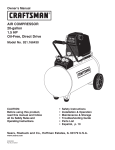
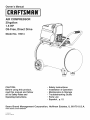
AiR COMPRESSOR
20-gallon
1.5 HP
Oil-Free, Direct Drive
Model No. 16914
CAUTION:
Before using this product,
read this manual and follow
all its Safety Rules and
Operating instructions.
Sears
Brand
Management
www.sears.com/craftsman
11/20/2012
Part No. E106446
•
•
•
•
•
•
Corporation,
Safety instructions
Installation & Operation
Maintenance & Storage
Troubleshooting
Guide
Parts List
Espa_ol, p. 12
Hoffman
Estates,
IL 60179
U.S.A.
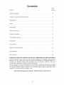
Table of Contents
Page
Warranty ..............................................................
Safety Symbols
See Below
..........................................................
1
Important Safety Instructions & Guidelines .....................................
1
Specifications
2
............................................................
Glossary ................................................................
2
Duty Cycle ..............................................................
2
Parts & Features ..........................................................
3
Installation & Assembly
4
Operating Procedures
Maintenance
Storage
....................................................
.....................................................
5
.............................................................
6
................................................................
Troubleshooting
6
Guide .....................................................
7
Exploded View ...........................................................
8
Parts List ...............................................................
9
EspaSol ................................................................
10
ONE YEAR
FULL WARRANTY
ON CRAFTSMAN
AIR COMPRESSOR
If this Craftsman Air Compressor fails due to manufacturer's defects in material or workmanship
within one year of the date of purchase, RETURN IT TO THE NEAREST SEARS STORE OR
SERVICE CENTER IN THE UNITED STATES and it will be replaced or repaired (at our option),
free of charge.
If this Air Compressor is used for commercial or rental purposes, this warranty applies for only 90
days from the date of purchase. This warranty gives you specific legal rights and you may also
have other rights which vary from state to state.
Sears Brand Management Corporation,
Hoffman Estates, IL 60179 U.S.A.
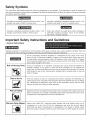
Safety Symbols
The information listed below should be read and understood by the operator. This information is given to protect the
user while operating and storing the air compressor. We utilize the symbols below to allow the reader to recognize important
information about their safety.
Indicates an imminently hazardous situation which, if not
avoided, will result in death or serious injury.
Indicates a potentially hazardous situation which, if not
avoided, may result in minor or moderate injury.
Indicates a potentially hazardous situation which, if not
avoided, could result in death or serious injury
When used without the safety alert symbol indicates a
potentially hazardous situation which, if not avoided,
may result in property damage.
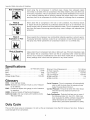
Important
Safety Instructions
and Guidelines
• Save all instructions
Improper operation or maintenance of this product could result in serious injury and/or property damage. Read and
understand all of the warnings and safety instructions provided before using this equipment.
The air compressor should be operated on a dedicated 15 amp circuit. If the circuit
does not have 15 free amps available, a larger circuit must be used. Always use more
air hose before utilizing extension cords. All extension cords used must be 12 gauge
with a maximum length of 25 ft. The circuit fuse type must be a time delay. Low voltage
could cause damage to the motor.
Risk of Moving
Parts
If the air compressor is in operation, all guards and covers should be attached or
installed correctly. If any guard or cover has been damaged, do not operate the
equipment until the proper personnel has correctly repaired the equipment. The power
cord should be free of any moving parts, twisting and/or crimping while in use and
while in storage.
Risk of Burns
There are surfaces on your air compressor that while in operation and thereafter can
cause serious burns if touched. The equipment should be allowed time to cool before
any maintenance is attempted. Items such as the compressor pump and the outlet
tube are normally hot during and after operation.
Risk of Failing
Operation of the air compressor should always be in a position that is stable. Never use
the air compressor on a rooftop or elevated position that could allow the unit to fall or
be tipped over. Use additional air hose for elevated jobs.
N
Risk from Flying Objects
Always wear ANSI Z87.1 approved safety glasses with side shields when the air
compressor is in use. Turn off the air compressor and drain the air tank before
performing any type of maintenance or disassembly of the hoses or fittings. Never
point any nozzle or sprayer toward any part of the body or at other people or animals.
1
Important
Safety Instructions & Guidelines
Avoid using the air compressor in confined areas. Always have adequate space
(12 inches) on all sides of the air compressor. Also keep children, pets, and others out
of the area of operation. This air compressor does not provide breathable air for anyone
or any auxiliary breathing device. Spraying material will always need to be in another
area away from the air compressor to not allow intake air to damage the air compressor
Risk of
Electrical Shock
Never utilize the air compressor in the rain or wet conditions. Any electrical issues
or repairs should be performed by authorized personnel such as an electrician and
should comply with all national and local electrical codes. The air compressor should
also have the proper three prong grounding plug, correct voltage, and adequate fuse
protection.
Risk of
E×plosion or Fire
Never operate the compressor near combustible materials, gasoline or solvent vapors.
If spraying flammable materials, locate the air compressor at least 20 feet away from
the spray area. Never operate the air compressor indoors or in a confined area.
Risk of Bursting
Always drain the air compressor tank daily or after each use. If the tank develops a leak,
then replace the air compressor. Never use the air compressor after a leak has been
found or try to make any modifications to the tank. Never modify the air compressor's
factory settings which control the tank pressure or any other function.
Specifications
Pump .........................
Motor ....................................
Bore .......................................
Stroke ......................................
Voltage Single Phase ......................
Oil-Free Direct Drive
1.5 HP
2.28"
0.87"
120 VAC
Minimum Circuit Requirement ..............
Air Tank Capacity ........................
Cut-in Pressure ...........................
Cut-out Pressure ..........................
SCFM @ 90 PSI ...............................
SCFM @ 40 PSI ...............................
15.0 Amps
20 Gallons
120 PSI
150 PSI
3.8
5.1
Glossary
CFM:
Cubic feet per minute.
SCFM: Standard cubic feet per minute;
for air delivery.
PSIG: Pounds per square inch gauge;
for pressure.
ASME: American Society of Mechanical
California Code: Unit may comply with
462 (I) (2)/(M) (2).
a unit of measure
a unit of measure
Engineers.
California Code
Cut=in Pressure: The air compressor will automatically
start to refill the tank when the pressure drops
below the prescribed minimum.
Cut-Out Pressure: The point at which the motor stops
when the tank has reached maximum air
pressure.
Code Certification:
Products that bear one or more of
the following marks: UL, ULc, ETL, CSA, have
been evaluated by OSHA-certified independent
safety laboratories and meet the applicable
Underwriters Laboratories Standards for Safety.
Duty Cycle
This is a 50% duty cycle air compressor.
could damage the air compressor.
Do not run the air compressor more than 30 minutes of one hour. Doing so
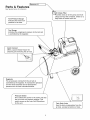
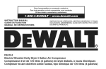
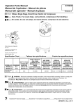
Parts & Features
IRemove
H.
See figures below for reference
Air intake Filter
rovides clean air to the pump and must
Iways be kept free of debris. Check on a
I
Tank Pressure Gauge
fl
ally basis or before each use.
Indicates the reserve air |
pressure in the tank.
J
Tool Gauge
Indicates the outgoing air pressure to the tool and
is controlled by the regulator.
I
uick Connect
Offers a quick release feature for
attaching
"_
|
an d removing the air hose.J
The air pressure coming from the air tank is
controlled by the regulator. To increase the pressure
turn
the knob clockwise and to decrease the
Regulator
}
pressure turn the knob counterclockwise.
/
Pressure Switch
"_
This controls the power to the motor and also I
the cut-in/cut-out
pressure settings. This
|
switch serves as the Auto-On/Off positions
|
.
for the unit.
J
I
ank Drain Valve
Used to drain condensation
"}
from the|
air tank. Located at bottom of tank. J
|
J
Parts & Features
See figures below for reference
Check Valve
When the pump is not in operation the valve
closes to retain air pressure inside the tank.
An internal component.
Outlet Tube
Pressure Relief Valve
The pressure relief valve located on the side of the
pressure switch, is designed to automatically
release compressed air when the air compressor
reaches cut-out pressure. The released air should
only escape momentarily and the valve should
then close.
i
ank Safety Valve
"]
Used to allow excess tank pressure to escape into |
the atmosphere. This valve should only open when |
the tank pressure is above the maximum rated
|
pressure,
j
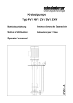
Installation & Assembly
The air compressor should be turned off, unplugged from
the power source, the air bled from the tank and the unit
allowed time to cool before any maintenance is performed.
Personal injuries could occur from moving parts, electrical
sources, compressed
air or hot surfaces. The quick
connect assembly must be attached before use. Failure
to assemble correctly could result in leaks and possible
injury. If unsure of assembly instructions or you experience
difficulty in the assembly please call your local service
department for further information.
j..J
,,i
Grounding
Grounded
Outlet
Pin
Getting Started = Location of the Air Compressor
The air compressor should always be located in a clean,
dry and well ventilated environment. The unit should have
at minimum, 12 inches of space on each side. The air filter
intake should be free of any debris or obstructions.
Check the air filter on a daily basis to make sure it is clean
and in working order.
Improper installation of the grounding plug will result in a
risk of electric shock. If repair or replacement of the cord
or plug is necessary, do not connect the grounding wire to
either flat blade terminal. The wire with insulation having
an outer surface that is green with or without yellow stripes
is the grounding wire. Check with a qualified electrician or
serviceman if the grounding instructions are not completely
understood, or if in doubt as to whether the product is
properly grounded. Do not modify the plug provided.
If it will not fit the outlet, have the proper outlet installed
by a qualified electrician.
Risk Of Fire Or Explosion
This product incorporates snap action switch contacts
and a universal electric motor which tend to produce arcs
and sparking and therefore should not be exposed to
flammable liquids or vapors. This product is not intended
for installation or use in a commercial garage or shop
environment.
This product is for use on a circuit having a nominal rating
of 120 volts and is factory-equipped with a specific electric
cord and plug to permit connection to a proper electric
circuit. Make sure the product is connected to an outlet
having the same configuration as the plug. An adapter
should not be used with this product. If the product must
be reconnected for use on a different type of electric circuit,
qualified service personnel should make the reconnection.
Extension
Grounding Instructions
This product should be grounded. In the event of an electrical
short circuit, grounding reduces the risk of electric shock
by providing an escape wire for the electric current.
This product is equipped with a cord having a grounding
wire with an appropriate grounding plug. (See the figure
below.) The plug must be plugged into an outlet that is
properly installed and grounded in accordance with all local
codes and ordinances. Check with a qualified electrician or
service personnel if these instructions are not completely
understood or if in doubt as to whether the tool is properly
grounded.
Cords
Use only a 3-wire extension cord that has a 3-blade
grounding plug and a 3-slot receptacle that will accept the
plug on the product. Make sure your extension cord is in
good condition. When using an extension cord, be sure to
use one heavy enough to carry the current your product
will draw. Cords must not exceed 25 feet and No. 12 AWG
size must be used. An undersized cord will cause a drop
in line voltage resulting in loss of power and overheating.
Break In Procedures
No break in procedure is required by the user.
This product isfactory tested to ensure proper operation and
performance.
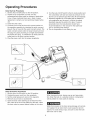
Operating Procedures
Daily Start=Up Procedures
1. Set the Auto-On/Off switch to the Off position.
2. Inspect the air compressor, air hose, and any
accessories/tools being used for damage or obstruction.
If any of these mentioned items are in need of repair/
replacement, contact your local authorized dealer before
use,
3. Close the drain valve.
4. Connect the air hose to the quick connect socket on
the regulator assembly by inserting the quick connect
plug on the air hose into the quick connect socket. The
quick connect socket collar will snap forward and lock
the plug into place providing an air tight seal between
the socket and plug. To release the air hose push the
collar back on the quick connect socket.
5. Plug the power cord into the proper receptacle.
Daily Shut=Down Procedures
1. Set the Auto-On/Off switch to the Off position.
2. Unplug the power cord from the receptacle.
3. Set the outlet pressure to zero on the regulator.
4. Remove any air tools or accessories.
5. Open the drain valve allowing air to bleed from the
tank. After all of the air has bled from the tank, close
the drain valve to prevent debris buildup in the valve.
6. Turn the Auto-On/Off switch to the On-Auto position and
the compressor will start and build air pressure in the
tank to cut-out pressure and then shut off automatically.
7. Adjust the regulator to a PSi setting that is needed for
your application and be sure it is within the safety
standards required to perform the task. If using a
pneumatic tool, the manufacturer should have
recommendations in the manual for that particular
tool on operating PSI settings.
8. The air compressor is now ready for use.
When draining the tank, always use ear and eye protection. Drain the tank in a suitable location; condensation
will be present in most cases of draining.
Water that remains in the tank during storage will corrode
and weaken the air tank which could cause the tank to
rupture. To avoid serious injury, be sure to drain the tank
after each use or daily.
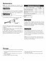
Maintenance
NOTE: Any service procedure
not covered
in the
maintenance schedule should be performed by qualified
service personnel.
I
The air compressor
should be turned off, unplugged
from the power source, air bled from the tank and
allowed
time to cool before any maintenance
is
items to Check/Change
Before each use
or daily
Check Tank Safety Valve
X
Overall Unit Visual Check
X
Drain Tank
X
Check Power Cord for Damage
X
Realign Warning
Icon
1
Do not attempt to remove or adjust the safety valve.
Check the safety valve by performing these three steps:
1. Plug the compressor in and run until shut-off pressure
is reached.
2. Wearing safety glasses, pull out on the safety valve ring
to release pressure from the tank.
3. The safety valve should close automatically
at
approximately at 40-50 PSI. If the safety valve does not
allow air to be released when you pull out on the ring, or
does not close automatically, it must be replaced.
To ensure efficient operation and longer life of the air
compressor unit, a routine maintenance schedule should
be followed. The following schedule is geared toward a
consumer whose compressor is used in a normal working
environment on a daily basis.
This compressor is equipped with an automatic reset
thermal overload protector which will shut off motor if it
becomes overheated. If the thermal overload protector is
actuated, the motor must be allowed to cool down before
start-up is possible.
NOTE: The motor will automatically
restart without warn-
ing if the unit is left plugged in to an outlet with the AutoOn/Off switch in the on position
Storage
For storing the air compressor, be sure to do the following:
1. Turn the unit off and unplug the power cord from the
receptacle.
2. Remove all air hoses, accessories, and air tools from
the air compressor.
3. Perform the daily maintenance schedule.
4. Open the drain valve to bleed all air from the tank.
5. Close the drain valve.
6. Store the air compressor
in a clean and dry location.
Troubleshooting
Guide
The air compressor should be turned off and unplugged from the power source before any
maintenance is performed as well as the air bled from the tank and the unit allowed time to cool.
Personal injuries could occur from moving parts, electrical sources, compressed air, or hot surfaces.
PROBLEM
POSSIBLE
Air leaks at the check
sure relief valve,
Air leaks between
valve or at the pres-
head and cylinder.
Air leak from safety
valve.
Pressure reading on the regulated
pressure gauge drops when an accessory
is used.
CORRECTION
A defective check valve results in a constant air leak at the pressure relief valve
when there is pressure in the tank and the compressor is shut off. Drain the tank,
then remove and clean or replace the check valve.
Be sure of proper torque on head bolts, tf leak remains, contact
cian.
a service techni-
Operate the safety valve manually by pulling on the ring. tf the valve continues to
leak when in the closed position, it should be replaced.
tf there is an excessive amount of pressure drop when the accessory is used,
replace the regulator.
Adjust the regulated pressure under flow conditions (while accessory is being
used), tt is normal for the gauge to show minimal pressure loss during initial use
of the tool.
Excessive tank pressure.
Move the Auto-On/Off switch to the Off position. If the unit doesn't shut off,
unplug it from the power source and contact a service technician.
Motor will not start.
Make sure power cord is plugged in and the switch is on. Inspect for the proper
size fuse in your circuit box. If the fuse was tripped, reset it and restart the unit. If
repeated tripping occurs, replace the check valve or contact a service technician.
Make sure the Thermal Overload Switch has not tripped. The motor has
a built in thermal cut out that trips when necessary to protect the motor
from damage when overheated.
To reset the motor overload toggle/turn the pressure switch Auto/Off lever to
the Off position and unplug the unit from the power outlet. Allow 10 minutes
(minimum) for motor overload cut-out to cool and reset. Unit can then be plugged
in and re-started.
Thermal overload protector cuts
out repeatedly.
1. Lack of ventilation, room temperature too high. Move to cooler
environment.
2. Excessive air usage, compressor too small for this application. Lower rate of
consumption.
Excessive moisture in the discharge air.
Remove the water in the tank by draining after each use. High humidity
environments will cause excessive condensation. Utilize water filters on your air
line.
Water condensation is not caused by compressor malfunction. Be sure the
compressor's air output is greater than your tool's air consumption rate.
Air leaks from the tank body or tank welds.
Never drill into, weld or otherwise modify the air tank or it will weaken. The tank
can rupture or explode. Compressor cannot be repaired. Discontinue use of the
air compressor.
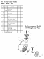
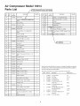
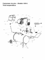
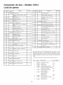
Air Compressor Model
16914 Parts List
Ref.
No.
Kit
No.
Part
Number
Description
Quantity
1
Screw, SHCS M6 X 1 X 35mm
4
2
Washer, Lock M6
4
Head, Cylinder
1
3
E100284
4
1&
10
Gasket,O-ring, Head (D Shape)
1
5
1
Assy, Valve Plate
1
6
1&
10
Gasket, O-ring Cylinder
1
7
2
Cylinder
1
Assy, Motor/Pump Housing F2B2
1
8
9
3
Screw, SHC M6 X 1 X 35mm
1
10
3
Assy, Eccentric and Bearing 6203ZC3
1
11
2
Assy,Connecting Rod/Piston
1
12
2
Screw, SHC M5 X.8 X 25mm
1
13
2
Nut, M5 x .8
1
14
4
Fan, Pump Cooling
1
15
4
Washer, Flat M6
1
16
4
Washer, Lock M6
1
17
4
Screw, SHC M6 X 1.0 X 16mm (Left
Hand)
1
18
E104273
Capacitor, Running
1
19
E104272
Capacitor, Starting
1
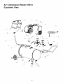
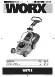
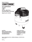
Air Compressor Model
16914 Exploded View
19 _\\
\\\\\
_11
_14
15
--16
17
13--
Air Compressor
E×ploded View
IVlodel 16914
/
/
lO
71
Air Compressor
Parts List
Model 16914
i_F2D2
Ref.
No.
Kit
No.
30
Motor/Pump
Part
Number
E105606
Shroud Rear Desc_
Quantity
1
Left
Hand t
Kit
No.
Part
Number
No.Ref'
64
5
Description
Quantity
Wheel, 7" x 1.5" Diamond Tread
2
65
5
Bolt, Shoulder M10 x 1.5 x 55mm
2
66
6
Ferrule
1
1
67
6
Nut Compression
1
Element, Air Filter
1
68
6
Outlet Tube
1
Cap, Air Filter
1
69
Elbow, Exhaust 90
1
Shroud Front
1
Screw, HFH M6 xl.0 x 16MM
6
36
Bolt, SHC M8 x 1.25 x 16MM ( ZDC
Plate)
4
71
E101
Cord, Power, 14/3 AWG, Length 6' Type
ST
1
37
Washer, Lock M8
10
72
E101800 _ Strain Relief, 14/3 AWG ST
38
Washer, Flat M8 x 19mm
4
39
Screw, SHC M6 x 1.0 x 16mm
2
Valve, Check 90
1
31
32
8
33
8
34
8
35
E100435
E105607
40
E100898
Assembly, F2D2 Moto_/PumpR=,_ht
',',c,nd
Outlet
1
Base, Air Filter
41
9
Ferrule 1/4"
2
42
9
Nut, Compression
2
43
9
Tube, Relief
1
44
E104075
Gauge Ring Tank
1
45
E103744
Gauge, Pressure 2'
2
46
E103951
Switch, Pressure Assy 150 psi 4 x 1//4"
NPT
1
47
E104074
Gauge Ring Tool
1
48
E100971
Regulator, 3-Port, 1/4" NPT
1
49
E100307
Quick Connect
1
50
E105883
Grip, Handle
1
51
E103485
Handle
1
52
E102612
Valve, Safety
1
53
E100853
Nipple, 1/4 mnpt x 35mm
1
54
E102857
Nipple, 1/4 mnpt x 43mm
1
Washer, Flat M8
6
55
56
Bolt, HH M8 x 1.25 x 20mm
4
57
Weldment Assy, Tank 20 Gallon
1
58
Nut, M8 x 1.25
59
E100240
60
61
62
63
E101717
5
5
70
ot
2
Screw, HH M8 x 1.25 x 30mm
2
Valve, Drain 1/4turn
1
Nut, Hex Lock Nylon M10 x 1.5 Brite
Zinc
2
1
I
E106522
Note:Anypartnumberfieldwithouta numberis notavailable.Descriptions
areprovided
forreference
only. TheKit# columnrepresents
thatthe partbeingofferedisavailablein
a kit.Oneofeachpartperkitwill beoffered.
Kitnumbers,descriptions,and includedcomponentsare listedbelow:
KitNo. PartNo.
Description
ReferenceNo.
1
E103497
Kit, Valve Plate
4-6
2
3
E103495
E104743
Kit, Piston
Kit, Eccentric
7,11-13
9-10
4
E104280
Kit, F2 Pump Fan
14-17
5
E104442
Kit, Wheel (replaces one
6
Isolator, Foot
Washer, Flat 10mm
-_
2
11
wheel assy.)
62-65
E103636
Kit, Finned Aluminum 3/8"
Outlet Tube
66-68
E104443
Kit, F2B2 Motor/Pump Assy
(Left Hand Exhaust)
1-19,31
8
E100794
Kit, AirFilter
33-34
9
E106473
Kit, Pressure Relief Tube1/4"
Aluminum
41-43
10
E105845
Kit, O-ring Gasket
4, 6
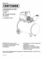
Manual de
CRRFTSl4Rli
COMPRESOR DE AIRE
75.7 lilros
1.5 HP
De impulsi6n direcla,
Sin aceite
# de Modelo 16914
PRECAUCION: Antes de usar
el producto, lea este manual y siga
sus reglas e instrucciones
de seguridad.
Sears
Brand
Management
• Instrucciones y pautas de seguridad
importantes
• Instalaci6n y operacion
• Mantenimiento y Almacenamiento
• Diagn6stico y correcci6n de fallas
• Lista de las piezas
Corporation,
www.sears.com/craftsman
11/20/2012
Part No. E106446
12
Hoffman
Estates,
IL 60179
U.S.A.
Contenido
PAgina
Garanfia
estapAgina
Simbolosde seguridad........................................................
12
Instruccionesy pautasde seguridadimportantes.......................................
12
Especificaciones............................................................
13
GIosario ................................................................
13
Ciclo de trabajo.............................................................
13
Partesy caracteristicas........................................................
14
Instalaci6ny ensamblaje.......................................................
15
Procedimientosde operaci6n....................................................
16
Mantenimiento.............................................................
17
AImacenamiento............................................................
17
Diagn6sticoy correcci6nde fallas.................................................
18
Vista esquemAfica...........................................................
19
Lista de las piezas...........................................................
20
GARANTiA
COMPLETA
DURANTE
UN Al_iO DEL COMPRESOR
DE AIRE CRAFTSMAN
Si este compresor de aire Craftsman fallase debido a defectos en materiales y mano de obra
dentro de un aSo a partir de la fecha de compra, DEVOLVERLO AL ESTABLECIMIENTO O
CENTRO DE SERVlCIO SEARS M,&S CERCANO EN LOS ESTADOS UNIDOS y 6ste sera
reemplazado o reparado (a nuestra opci6n), gratuitamente.
Si este compresor de aire se utiliza para fines comerciales o de alquiler, esta garantia es valida
solo durante 90 dias a partir de la fecha de compra. Esta garantia brinda al comprador original
del producto derechos legales especfficos; el comprador original tambien podria tener otros
derechos, los cuales varian de un estado a otro.
Sears Brand Management Corporation,
13
Hoffman Estates, IL 60179 U.S.A.
SJmbolos comunes de seguridad
El operador debe leer y entender la informaci6n descrita a continuaci6n. Esta informaci6n se ofrece para proteger al
usuario al operar y almacenar el compresor de aire. Los simbolos siguientes son los que se utilizan para indicar al lector
informaci6n que es importante para su seguridad.
Indica una situaci6n de riesgo inminente que, al no
protegerse, provocara lesiones graves o la muerte.
tndica una situaci6n potencialmente peligrosa que, de no
evitarse, podr[a provocar lesiones menores o moderadas.
Indica una situaci6n potencialmente peligrosa que, al no
protegerse, podria provocar lesiones graves o la muerte.
Cuando no aparezca sin el s[mbolo de aterta de seguridad, 6sto
quiere decir que hay una situaci6n potencialmente peligrosa
que, al no protegerse, podr[a causar da_os materiales.
nstrucciones y pautas de seguridad importantes
• Guarde todas
las instrucciones
La operaci6ny el mantenimientoinadecuadosde este productopuedenprovocarlesionesgravesy da_os materiales.Antesde utilizareste equipo,
lea y entiendalas advertenciase instruccionesde seguridadaqu[ contenidas.
El compresor de aire se debe operar desde un circuito especial de 15 amperios.
Si el circuito no dispone de una capacidad de 15 amperios, se debe usar un circuito
de mayor capacidad. Si es necesario, antes de emplear una extensi6n el6ctrica, a_ada
una manguera de aire m_s larga. Las extensiones el6ctricas deben set de calibre 12
y tener una Iongitud m_xima de 7,6 metros. El fusible del circuito debe ser de acci6n
retardada. Un voltaje demasiado bajo puede da_ar el motor.
Riesgo pot partes en
rnovirniento
AI operar
el compresor, todos los protectores y cubiertas deben estar fijados e
instalados correctamente. Si alguno de los protectores o cubiertas esta da_ado, no
opere el equipo hasta que personal calificado repare el problema. El cable de corriente
debe mantenerse alejado de las partes m6viles del equipo y no debe torcerse ni
prensarse durante su empleo, ni al almacenarse.
En su compresor hay superficies que, al set tocadas durante y despu6s de su
operaci6n, pueden causar quemaduras graves. Antes de darle mantenimiento al
equipo, se debe dejar enfriar. Por Io normal, durante y despu6s de su operaci6n,
ciertas partes como la bomba del compresor y el tubo de salida estaran calientes.
El compresor siempre debe set operado en una posici6n estable. Nunca utilice el
compresor sobre un techo o en una posici6n elevada ya que podr[a caer o
volcarse. AI trabajar en posiciones elevadas, utilice una manguera de aire mas larga.
Riesgo de lanzarniento
de objetos
AI emplear el compresor, siempre utilice anteojos de seguridad con protectores
laterales que cumplan con la norma ANSI Z87.1. Antes de Ilevar a cabo cualquier clase
de mantenimiento y antes de desconectar las mangueras y los acopladores, apague
el compresor y drene el tanque de aire. Nunca apunte la boquilla o el rociador hacia
ninguna parte de su cuerpo, ni 61de otros seres.
14
Instrucciones y pautas de seguridad importantes
Riesgo para la
respiraci6n
Evite utilizar el compresor de aire en Areas encerradas. Siempre tenga un espacio
libre adecuado (30 cm.) en todos los lados del compresor. Tambien mantenga fuera
del Area de operaci6n alas mascotas, ni_os y otras personas. Este compresor de aire
no provee aire que pueda ser respirado ni empleado con un dispositivo respiratorio
auxiliar. El material de rociado siempre debera estar en otra zona, alejado del compresor
de aire, para evitar que el aire aspirado da_e al filtro del compresor.
Nunca utilice el compresor de aire bajo Iluvia o en lugares mojados. Los problemas
electricos deben set reparados por personal autorizado, tal como seria un electricista,
y deben cumplir con las normas electricas nacionales y locales. El compresor tambien
debe tenet la clavija apropiada de tres terminales para hacer tierra y contar con
un suministro electrico que sea del voltaje correcto y con un fusible de protecci6n
adecuado.
Riesgo de
explosi6n
y fuego
Nunca opere el compresor cerca de materiales combustibles, gasolina ni vapores
de solventes. Siesta rociando materiales inflamables, coloque el compresor a una
distancia de cuando menos 6 metros del Area de rociado. Nunca opere el compresor
de aire en interiores o en lugares cerrados.
Drene el compresor diariamente o despu6s de cada utilizaci6n. Si el tanque tiene una
fuga, reemplace el compresor. Nunca utilice el compresor si se ha detectado una fuga,
nitrate de modificar el tanque. Nunca modifique los ajustes de fAbrica del compresor
que controlan la presi6n del tanque y demas funciones.
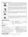
Especificaciones
Bomba .....................
Sin aceite, De impulsi6n
directa
Capacidad del tanque de aire ...............
75.7 litros
Presi6n de arranque .............
827.4 KPa / 120 PSI
Presi6n de parada ..............
1034.2 KPa / 150 PSI
PiescQbicospor minuto(SCFM)a 90 LPPC.....................
3.8
PiescQbicospor minuto(SCFM)a 40 LPPC.....................
5.1
Motor ...........................
1.5 HP (Universal)
Diametro ..................................
58 mm
Carrera ...................................
22 mm
Voltaje monofasico ........................
120 VAC
Capacidad minima del circuito ................
15.0 A
Glosario
CFIVI:
Pies cObicos por minuto.
SCFM: Pies cObicos estandar por minuto;
medici6n de suministro del aire.
PSlG:
unidad
Presi6n de arranque: El compresor arranca automaticamente cuando la presi6n baja a menos del minimo
prescrito.
Presi6n de parada: El motor se para cuando el tanque
alcance la presi6n maxima de aire.
Certificaci6n
de c6digo:
Los productos que tienen
alguna o varias de las siguientes marcas han sido
evaluados
por
laboratorios
de seguridad
independientes certificados por OSHA, y cumplen
con las normas de seguridad de Underwriters
Laboratories: UL, , ETL, CSA.
de
Libras por pulgada cuadrada sobre la presi6n
atmosferica; unidad de medici6n de presi6n.
ASME: Sociedad estadounidense de ingenieros mecanicos.
C6digo
de California: La unidad puede cumplir
c6digo de California 462 (I) (2)/(M) (2).
con el
Ciclo de trabajo
Estecompresortiene un ciclo de trabajode 50%. Nuncaopereel compresorpor m&sde 30 minutoscadahora.
Ya que al hacerlo,podriadaSarlo.
15
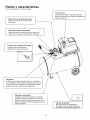
Partes y caracterfsticas
Como
referencia,
yea las figuras
abajo.
Suministra aire limpio a la bomba. Siempre
debe conservarlo limpio. Revfselo diariamente
Filtro de
delcada
aire uso.
antes
I
I
Indica la presi6n de la reserva de aire
Man6metro
de presi6n del tanque
del
tanque.
1
Man6rnetro
para herramientas
Indica la presi6n de salida del aire que entra en la
herramienta, la cual que es controlada pot el regulador.
Conector
de acoplarniento
r_pido
Permite conectar y desconectar
r_.pidamente la manguera del aire.
Regulador
La presi6n del aire que sale del tanque es controlada
por el regulador. Para aumentar la presi6n, gire la perilla
en direcci6n de las manecillas; para disminuirla, gire la
perilla en direcci6n contraria a las manecillas.
/
I
Controla el suministro el6ctrico en el motor y
tambi_n los ajustes de presi6n de arranque y
presi6n de parada. Este interruptor sirve como
Interruptorde autoencendido
de presion
posici6n
y apagado (Auto=On/
1
Off) de la unidad.
I
16
Sirve para drenar la condensaci6n
acumulada
el rondo del tanque. Se
V_lvula de en
drenaje
encuentra en la parte inferior del tanque.
1
ol
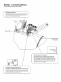
Partes y caracteristicas
Como
referencia,
yea las figuras
abajo.
Vblvula de retenci6n
Cuando Ja bomba no estA en operaci6n, esta v&lvula
se cierra para retener Japresi6n de aire dentro del
tanque. Es un componente interno.
Outlet Tube
Tubo de alivio
de presi6n
V_lvula de alivJo de presi6n
Esta v;&lvuJa, que se encuentra en el costado del
interruptor de presi6n, estA diseSada para liberar
aire comprimido de manera autom_.tica cuando el
compresor Ilegue a la presi6n de parada. El aire s61o
deberA escapar durante un instante, cerrAndose la
vAIvula se cerrarA en seguida.
V_ivula
de seguridad
del tanque
"/
Permite que el exceso de presi6n en el tanque escape
hacia el medio ambiente. Esta v_.lvula s61o se abrir_.
cuando Ja presi6n en el tanque est6 por encima de Ja
|
|
|
presi6n m&xima nominal deJ modeJo.
J
17
Instalaci6n y ensamblaje
Antes de darle cualquier tipo de mantenimiento
al
compresor de aire, se debe apagar y desconectar de la
fuente de alimentaci6n el6ctrica, ademas de purgar el aire
del tanque y darle suficiente tiempo para enfriarse. Existe
el riesgo de que las partes m6viles, las fuentes electricas,
el aire comprimido y las superficies calientes provoquen
lesiones. El ensamblaje de conexi6n rapida debe estar
instalado antes de usar el compresor. Un ensamblaje
inadecuado puede set causa de fugas y posiblemente
de lesiones. En caso de dudas sobre las instrucciones
de montaje o dificultad en el montaje, pot favor Ilamar al
departamento de servicio local para mayor informaci6n
C/avija
/'
Terminal de
tierra
Una conexi6n a tierra inadecuada puede provocar una
descarga el6ctrica. Si necesita reparar o cambiar el cable
o la clavija, no conecte el alambre de tierra con ninguna
de las terminales planas. El alambre de tierra es de
color verde, con o sin franjas amarillas. Si no entiende
completamente
las instrucciones de conexi6n a tierra,
o si tiene dudas sobre la correcta puesta a tierra de la
herramienta, hable con un electricista o agente de servicio
calificado. No modifique la clavija que viene con el equipo;
si no puede enchufarla en el tomacorriente, Ilame a un
electricista calificado para que le instale el tomacorriente
adecuado.
Este producto esta diseffado para trabajar en un circuito
con un voltaje nominal de 120 voltios y esta equipado en
la f_brica con un cable y clavija que permiten su conexi6n
a un circuito electrico apropiado. Aseg0rese de que el
producto este conectado a un tomacorriente con la misma
configuraci6n que la clavija. No se debe usar un adaptador
con este equipo. Si debe conectar el equipo con un
circuito electrico de diferente tipo, consiga la ayuda de
personal calificado para realizar la reconexi6n.
Primer paso: Ubicaci6n del compresor del aire
El compresor del aire siempre debe estar en un medio
ambiente limpio, seco y bien ventilado. La unidad debe
tener por Io menos 30 cm de espacio libre en cada lado.
La toma del filtro del aire debe estar limpia y sin ningOn
tipo de obstrucci6n. Examinar el filtro de aire diariamente
para verificar que est6 limpio yen buenas condiciones de
funcionamiento.
Riesgo de incendio o explosi6n
Este producto incorpora un interruptor con contactos
de transici6n brusca y un motor electrico universal que
tienden a producir arcos y chisporroteo.
Pot Io tanto, no
se Io debe exponer a liquidos o vapores inflamables. Este
producto no esta previsto para uso o instalaci6n en un
entorno de garaje o taller comercial.
Cables de extensi6n
S61o utilice un cable de extensi6n de tres alambres con
una clavija con extensi6n a tierra de tres terminales que
pueda enchufarse en un tomacorriente de tres orificios.
Aseg0rese de que su cable de extensi6n est6 en buenas
condiciones. Si utiliza un cable de extensi6n, compruebe
que sea de la capacidad de la corriente que requiere su
equipo. Las extensiones no deben ser de mas de 25 pies
(7,6 m) de largo y deben tener cable de calibre 12 AWG.
Un cable mas delgado provocara una caida en el voltaje
de la linea, Io que provocaria una p@dida de potencia y
sobrecalentamiento.
Instrucciones de conexi6n a tierra
Este producto se debe conectar a tierra. En el caso de
que haya un cortocircuito, la conexi6n a tierra reduce el
riesgo de descargas electricas al ofrecer una ruta de
escape para la corriente electrica. Este producto cuenta
con un cable que tiene un alambre de tierra y una clavija
con terminal de tierra (ver la figura a continuaci6n).
La
clavija debe enchufarse en un tomacorriente
instalado
y puesto a tierra seg0n las normas locales. Hable
con un electricista o agente de servicio calificado si
no entiende completamente
estas instrucciones,
o
si tiene dudas sobre la correcta puesta a tierra de la
herramienta.
Procedimiento inicial de preparaci6n
No se requiere un procedimiento inicial de preparaci6n.
Este producto ha sido probado en la fabrica para asegurar
su operaci6n y rendimiento adecuados.
18
Procedures d' utilisation
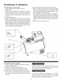
Procedimiento diario de arranque
1. Pongael interruptor
Auto-On/Often la posici6nde
apagado(Off).
2. Verifiqueque el compresordel aire,la manguerade aire y todoslos
accesorios/herramientas
utilizados,no tengandaSosni obstrucci6n.
En casode dudassobrelasinstrucciones
de montajeo dificultaden el
montaje,por favorIlamaral departamento
de serviciolocalparamayor
informaci6n.
3. Cierrela v_.lvuiade drenaje.
4. Enchufela mangueradel aire dentrodel conectorde acopiamiento
r@ido de la unidaddel regulador,insertandola clavija de conexi6n
r@idaen la mangueradel aire,dentrodelconectorde acoplamiento
r@ido. El collarindel conectorde acoplamientor@idosaltar_,hacia
adelante,sujetandola clavijay har_.una juntaentreel conectory la
clavija.Para desconectarla mangueradel aire, empujehaciaatr_.s
el collarindel conectorde acoplamientor@ido.
Procedimiento
diarJo de apagado
1. Colocar la palanca de encendido/apagado
la posici6n apagado (Off)
2. Desconecte el cable del tomacorriente.
5. Enchufeel cable de corrienteen un tornacorrienteapropiado.
6. Mueva el interruptor Auto-On/Off a la posici6n de encendido
(Auto-On); el compresordeber_,arrancar,acumuiandola presi6n
del aire en el tanquehastaIlegara la presi6nde apagado,momento
en el cual se apagar_,de maneraautom_.tica.
7. Ajustarel reguladora un valorde bar (psi)que sea necesariopara
el uso previstoy verificarque este dentro de los est_.ndaresde
seguridadrequeridospararealizarlatarea.Si seutilizaunaherramienta
neum_.tica,
el fabricantedebe haber incluidoen el manualde dicha
herramientavaloresrecomendados
parala presi6nde servicioen bar
(psi).
8. Ahorael compresorde aire est,.listoparauso.
(On/Off) en
AI drenar el tanque utilice protecci6n para oidos y ojos.
Drene el tanque en un lugar apropiado; en la mayoria de
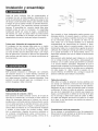
las ocasiones al drenar saldrb, condensaci6n.
3. Ponga en cero el regulador de presi6n de salida.
4. Quite todas las herramientas o accesorios de aire.
5. Abra la valvula de drenaje permitiendo que escape el
aire del tanque. Cuando haya salido del tanque todo el
aire, cierre la vb.lvula de drenaje para evitar que entre
suciedad.
Si no drena el tanque al almacenarlo, en su interior
quedara agua que Io corroerb, y debilitarb., Io cual puede
provocar su ruptura. Para evitar lesiones graves, drene el
tanque diariamente o despu6s de cada uso.
19
Mantenimiento
Cualquier procedimiento
de servicio que no est6
cubierto en el programa de mantenimiento
que sigue
deberb, set efectuado el personal de servicio calificado.
Antes de dar mantenimiento
al equipo, se debe apagar
y desconectar
del tomacorriente,
asi como purgar el
aire del tanque y permitir que la unidad se enfde.
Asuntos para verificar/cambJar
Antes de cada uso
o diariamente
RevisarlavAIvuladeseguridad
deltanque
X
Revisarvisualmenteel aspectogeneral
de la unidad
X
Drenarel tanque
X
Verificarque el cableel@tricono est_
dafiado
X
no intentar retirar o ajustar la valvula de seguridad
A fin de asegurar una operaci6n eficiente y una larga vida
del compresor, debe seguir un programa de mantenimiento
de rutina. El siguiente programa de mantenimiento estb.
enfocado al consumidor cuyo compresor es usado en un
medio ambiente normal y diariamente.
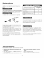
Revisar la valvula de seguridad mediante la ejecuci6n de
los tres pasos siguientes:
1. Enchufar el compresor y hacerlo funcionar hasta que
alcance la presi6n de desconexi6n.
2. Con gafas de seguridad puestas, tirar del aro de la valvula de seguridad para aliviar la presi6n del tanque. Usar
la otra mano para desviar el aire o despojos expelidos a
alta velocidad para protegerse la cara.
3. La valvula de seguridad debe cerrarse autom_tticamente a una presi6n aproximada de 2.8 a 3.4 bar (40 a
50 psi). Si la valvula de seguridad no permite la salida
del aire al tirarse del aro, o no cierra automaticamente, es
preciso reemplazarla.
Este compresor es equipado con un autom_ttico repone
protector t@mico de sobrecarga que apagara el motor si
Ilega a set recalentado. Si el protector t@mico de sobrecarga es accionado, el motor debe set permitido enfriarse
antes de puesta en marcha es posible.
La NOTA: El motor reiniciara automaticamente sin la advertencia si la unidad es dejada conect6 a una salida con
el interruptor de en/de prendido
Almacenamiento
Para almacenar el compresor, asegt_rese de hacer Io siguiente:
1. Apague la unidad y desconecte
tomacorriente.
2. Quite del compresor
herramientas de aire.
4. Abra la valvula de drenaje para drenar el aire del
tanque.
5. Cierre la valvula de drenaje.
6. Guarde el compresor en un lugar limpio y seco.
el cable electrico del
las mangueras,
accesorios
3. Ueve a cabo el programa de mantenimiento
y
de rutina.
2O
Diagn6stico y correcci6n de fallas
Antes de dar mantenimiento al equipo, se debe apagar y desconectar del tomacorriente, asf
como purgar el aire del tanque y permitir que la unidad se enfrfe. Las partes en movimiento, las
fuentes electricas, el aire comprimido y las superficies calientes pueden provocar lesiones.
PROBLEMA
POSIBLE CORRECCION
Fuga de aire en la valvula de retenci6n o
en la valvula de alivio.
Una valvuta de retencion defectuosa provoca una fuga de aire constante en la
valvuta de alivio cuando este apagado y el compresor tenga presion de aire.
Drene el tanque, quite y limpie o cambie la valvula de retencion.
Fugas de aire entre la cabeza Name a un
t6cnico de servicio.
Compruebe que los pernos de la cabeza tengan un par apropiado.
fuga, el cilindro.
Fuga de aire en la valvula de seguridad.
Opere manualmente la valvuta de seguridad jalando el anillo. Si et tanque continOa teniendo una fuga estando la valvula en posicion cerrada, debera cambiarla.
La presi6n indicada en el man6metro de
presi6n regulada bajara cuando se utiliza
un accesorio.
Si al utitizar un accesorio
regulador.
hay una disminucion
Si continOa la
excesiva de presion, cambie el
Ajuste la presion regulada bajo condiciones de flujo (mientras se utiliza un
accesorio). Es normal que el manometro indique una disminucion de presion
mfnima al comenzar a utilizar la herramienta.
Presi6n excesiva
en el tanque.
Apague et interruptor de encendido (Off). Si la unidad no se apaga, desconectela
del tomacorriente y comunfquese con un tecnico de servicio.
El motor no arranca.
Compruebe que el cable de corriente est6 enchufado y que el interruptor est6
encendido Compruebe que el fusible de la caja de circuitos sea de la capaci=
dad adecuada. Si se ha disparado, restabl_zcalo y vuelva a arrancar la unidad.
Si el fusible se dispara con frecuencia, reemplace la v_.lvula de retenci6n
o Ilame a un t6cnico de servicio. Assurez-vous que I'interrupteur du dispositif
contre les surcharges thermiques n'a pas 6t6 d_clench6. Le moteur poss_de un
coupe-circuit thermique int6gr6 qui se d6clenche Iorsqu'il est n6cessaire de prot6=
ger le moteur de dommages dus & la surchauffe. Pour r6initialiser la commande &
bascule de surcharge du moteur, placez le levier du manostat "ON/OFF" en position "OFF" et d6branchez I'unit6 de la source d'alimentation. Attendez 10 minutes
(minimum) pour que le coupe-circuit de surcharge de moteur puisse refroidir et se
r6initialiser. Par la suite, I'unit_ peut _tre branch6e et d6marr6e & nouveau.
El protector contra sobrecarga t6rmica se
desconecta repetidamente.
1. Falta de ventitacion, temperatura
entorno mas fresco.
ambiente demasiado
2. Uso excesivo de aire; compresor
la tasa de consumo.
demasiado peque_o para este uso. Reducir
Humedad excesiva en el aire de salida.
alta. Desplazarlo a un
Saque el agua del tanque drenandoto despues de cada vez que se use. En los
medios ambientes de alta humedad habra un exceso de condensacion; instale
filtros de agua en su Ifnea de aire.
La condensacion no es provocada pot una falla en el compresor. Compruebe que
la salida de aire del compresor sea mayor que el consumo del aire de su herramienta.
Fugas de aire en el cuerpo o la soldadura
del tanque.
Nunca taladre, suelde o modifique de ninguna manera et tanque, pues se
debititara. El tanque podrfa romperse o explotar. El tanque no puede ser
reparado.
21
Compresor de aire - Modelo 16914
Lista de partes
Ref.
No.
Kit
No.
Part
Number
Description
Quantity
1
TORNILLO, SHCS M6 X 1 X 35 MM
4
2
ARANDELA DE FRENO M6
6
CULATA DE ClLINDRO
1
3
E100284
4
1&
I0
JUNTA EN "0", CULATA (FORMA DE
"D")
1
5
1
CONJUNTO, PLACA DE V,4LVULA
1
6
1&
10
JUNTA EN "O', CILINDRO
1
7
2
CILINDRO
1
CONJUNTO, CAJA DE MOTOR/BOMBA
F2B2
1
8
9
3
TORNILLO, SHC M6 X 1 X 35 MM
1
10
3
CONJUNTO, EXCENTRICO Y
COJINETE 6203ZC3
1
11
2
CONJUNTO, BIELA / PISTON
1
12
2
TORNILLO, SHC M5 X.8 X 25 MM
1
13
2
TUERCA, M5 X .8
1
14
4
VENTILADOR, ENFRIAMIENTO DE
BOMBA
1
15
4
ARANDELA PLANA M6
1
16
4
ARANDELA, DE FRENO M6
1
17
4
TORNILLO, SHC M6 X 1.0 X 16 MM
(MANO IZQUIERDA)
1
18
E104273
CONDENSADOR DE MARCHA
1
19
E104272
CONDENSADOR DE ARRANQUE
1
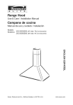
Compresor de aire
Modelo 16914
Vista esquem_tica
19_\\
\\\\
18_
_12
/
13
22
_14
Compresor de aireVista esquem_tica
IVlodelo 16914
/
/
/
31
/_32
/
/
/'
/
/_ 71
/
/
/
/
/
/
_41
i
i
_5o
i/--51
\
_65
23
Compresor de aireLista de partes
Ref.
No.
Kit
No.
30
Part
Number
E105606
IVlodelo 16914
Description
Quantity
6
56
Perno, HH M8 x 1.25 x 25 mm
4
57
Ensamble soldado, tanque de 20
galones
1
58
Tuerca, M8 x 1.25
6
Pie, aislante
2
Tornillo, HH M8 x 1.25 x 30 mm
2
V_.lvulade drenaje 1/4 de vuelta
1
32
8
Base, filtro de aire
1
33
8
Elemento, filtro de aire
1
34
8
Tapa, filtro
1
Caja, parte delantera
1
Perno, SHC M8 x 1.25 x 16 mm (Placa
ZDC)
4
37
Arandela de freno M8
10
38
Arandela plana M8 x 19 mm
4
39
Tomillo, SHC M6 x 1.0 x 16 mm
2
V_.lvulade retenci6n 90
1
40
E100898
Quantity
Arandela plana M8
1
36
Description
55
Conjunto, motor/bomba F2B2 - Salida a
la derecha
E105607
Part
Number
1
7
35
Kit
No.
Protectortrasero
31
E100435
Ref.
No.
59
E100240
60
61
41
9
Casquillo 1/4 pulg.
2
42
9
Tuerca de compresi6n
2
43
9
Tubo de alivio
1
44
E104075
Aro man6metro-Tanque
1
45
E103744
Man6metro, 2 pulg.
2
46
E103951
Conjunto, Interruptor a presi6n 150 psi 4
x 1//4" NPT
1
47
E104074
Aro man6metro- Herramientas
1
48
E100971
Regulador, 3-Puertos, 1/4 pulg. NPT
1
49
E100307
Conexi6n r_.pida
1
50
E105883
Toma, agarradera
1
51
E103485
Agarradera
1
52
E102612
V_.lvulade seguridad
1
53
E100853
Boquilla, 1/4 mnpt x 35 mm
1
54
E102857
Boquilla, 1/4 mnpt x 43 mm
1
E101717
62
5
Tuerca hex de seguridad, nil6n M10 x
1.5, cinc brillante
2
63
5
Arandela plana 10 mm
2
64
5
Rueda, banda en rombo, 7 x 1.5 pulg.
2
65
5
Perno de espald6n, M10 x 1.5 x 55 mm
2
66
6
Casquillo
1
67
6
Tuerca de compresi6n
1
68
6
Tubo de salida
1
Codo de escape 90
1
Tornillo, HFH M6 xl.0 x 12 mm
6
Cord6n electrico, 14/3 AWG, Iongitud 6
1
69
E100283
70
71
E101073
pi - tipo ST
72
E101800
Protector, 14/3 AWG ST
1
Nora: Cualquier campo para los numeros/juegosde piezas que no tengan un numero
especifico de pieza, indica que no esta disponible. Las descripciones se proveen
solamente como referencias.La columna con el numero de juego indica que la pieza
ofrecida esta disponiblecomo parte de un juego. Una de cada una de las piezas esta
ofrecida.
Losnurneros
de kit,descripciones
y componentesincluidosseenurneran
a continuaci6n:
Juego #
24
Pedido#
Nornbredeljuego
Ref.# Componente
1
E103497
Juego, Placa dev_.lvula
4-6
2
E103495
Juego, Pist6n
7,11-13
3
E104743
Juego, Excentrico
9-10
4
E104280
Juego, F2Ventiladordebomba
14-17
5
E104442
Juego, Rueda (reemplaza solamente
el conjunto de una rueda)
62-65
E103636
Juego,Tubo de salida 3/8pulg.
de alum. con aletas
66-68
E104443
Juego, Conjunto,caja de
motorfoombaF2B2
(salida manoizqu.)
1-19,31
8
E100794
Juego, Filtro de aire
33-34
9
E106473
Juego, Tubo de alivio de presi6n,
10
E105845
1/4 pulg. de Alum.
41-43
Juego, Junta en"O"
4, 6
Papapedipsepviciode repapacion
a domicifio,y papaordenappiezas:
1-888-SU-HOGAR
_
11-888-784-6427)
AuCanadapourserviceen fran_ais:
1-800-LE-FOYER
"R
{1-800=553-8837)
www.seaps,ca
® Registered Tredemarb/TM Tradomarb/SMService Mark of Soars,RoebuckandCo.
® Merca ReHistrede/TM Nerce de Fabrica/SpANerca de RerviciodeSears, RoebecbendCo.
McNarque de commerce/pAo
IViarquo
deposeede Soars,RoebuckendCo.
®SeePs Breeds,LLC