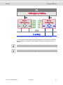
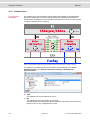
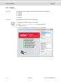
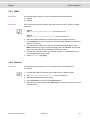
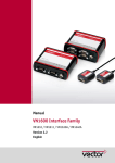
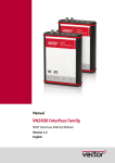
1
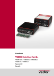
Manual CANcaseXL CANcaseXL log Version 5.1 English Imprint Vector Informatik GmbH Ingersheimer Straße 24 D-70499 Stuttgart The information and data given in this user manual can be changed without prior notice. No part of this manual may be reproduced in any form or by any means without the written permission of the publisher, regardless of which method or which instruments, electronic or mechanical, are used. All technical information, drafts, etc. are liable to law of copyright protection. Copyright 2013, Vector Informatik GmbH. Printed in Germany. All rights reserved. Art. 80082 Manual Table of contents Table of contents 1 Introduction 3 1.1 About this User Manual 1.1.1 Certification 1.1.2 Warranty 1.1.3 Registered trademarks 4 5 5 5 2 CANcaseXL and CANcaseXL log 7 2.1 Introduction 8 2.2 Driver Installation 8 2.3 Connectors 2.3.1 USB Connector 2.3.2 Binder Connector 2.3.3 External Trigger Input (CANcaseXL log only) 2.3.4 D-SUB9 Connector 8 9 9 9 9 2.4 Synchronization 9 2.5 LED Display 10 2.6 Additional Features on CANcaseXL log 2.6.1 Operating Modes 2.6.2 Additional LEDs 2.6.3 Piezo Buzzer 2.6.4 Memory Card 2.6.5 Battery 2.6.6 CANcaseXL log Flowchart 11 11 11 12 12 13 14 2.7 Replacing Piggybacks 15 2.8 Technical Data 16 3 CANcaseXL/log Accessories 17 3.1 Accessories 18 4 Common Features 19 4.1 Time Synchronization 4.1.1 General Information 4.1.2 Software Sync 4.1.3 Hardware Sync 20 20 22 23 5 Driver Installation 25 5.1 Minimum Requirements 26 5.2 Hints 26 5.3 Vector Driver Setup 27 5.4 Vector Hardware Configuration 29 5.5 Loop Tests 5.5.1 CAN 5.5.2 FlexRay 5.5.3 MOST 5.5.4 Ethernet 31 31 34 35 35 © Vector Informatik GmbH Version 5.1 -I- Manual Introduction 1 Introduction In this chapter you find the following information: 1.1 About this User Manual Certification Warranty Registered trademarks © Vector Informatik GmbH page 4 Version 5.1 -3- Introduction 1.1 Manual About this User Manual To find information quickly This user manual provides you with the following access help: At the beginning of each chapter you will find a summary of the contents In the header you can see in which chapter and paragraph you are Conventions In the two following charts you will find the conventions used in the user manual regarding utilized spellings and symbols. Style Utilization bold Blocks, surface elements, window- and dialog names of the software. Accentuation of warnings and advices. [OK] Push buttons in brackets File|Save Notation for menus and menu entries Microsoft Legally protected proper names and side notes. Source Code File name and source code. Hyperlink Hyperlinks and references. <CTRL>+<S> Notation for shortcuts. Symbol Utilization Here you can obtain supplemental information. This symbol calls your attention to warnings. Here you can find additional information. Here is an example that has been prepared for you. Step-by-step instructions provide assistance at these points. Instructions on editing files are found at these points. This symbol warns you not to edit the specified file. -4- Version 5.1 © Vector Informatik GmbH Manual Introduction 1.1.1 Certification Certified Quality Vector Informatik GmbH has ISO 9001:2008 certification. The ISO standard is a Management System globally recognized standard. 1.1.2 Warranty Restriction of warranty We reserve the right to change the contents of the documentation and the software without notice. Vector Informatik GmbH assumes no liability for correct contents or damages which are resulted from the usage of the documentation. We are grateful for references to mistakes or for suggestions for improvement to be able to offer you even more efficient products in the future. 1.1.3 Registered trademarks Registered trademarks All trademarks mentioned in this documentation and if necessary third party registered are absolutely subject to the conditions of each valid label right and the rights of particular registered proprietor. All trademarks, trade names or company names are or can be trademarks or registered trademarks of their particular proprietors. All rights which are not expressly allowed are reserved. If an explicit label of trademarks, which are used in this documentation, fails, should not mean that a name is free of third party rights. Windows, Windows XP, Windows Vista, Windows 7 are trademarks of the Microsoft Corporation. © Vector Informatik GmbH Version 5.1 -5- Manual CANcaseXL and CANcaseXL log 2 CANcaseXL and CANcaseXL log In this chapter you find the following information: 2.1 Introduction page 8 2.2 Driver Installation page 8 2.3 Connectors USB Connector Binder Connector External Trigger Input (CANcaseXL log only) D-SUB9 Connector page 8 2.4 Synchronization page 9 2.5 LED Display page 10 2.6 Additional Features on CANcaseXL log Operating Modes Additional LEDs Piezo Buzzer Memory Card Battery CANcaseXL log Flowchart page 11 2.7 Replacing Piggybacks page 15 2.8 Technical Data page 16 © Vector Informatik GmbH Version 5.1 -7- CANcaseXL and CANcaseXL log 2.1 Manual Introduction CANcaseXL The CANcaseXL is a USB interface with a powerful 32 bit 64MHz microcontroller from ATMEL with ARM7 Core and two SJA1000 CAN controllers from Philips. It can process CAN messages with either 11-bit or 29-bit identifiers. It is also possible to receive and analyze Remote Frames without any limitations. The CANcaseXL is also capable of generating and detecting Error frames on the bus. CANcaseXL log The CANcaseXL log offers the same features as the CANcaseXL, but it can also be used as a data logger for CAN and LIN messages. The logged data is saved on industrial-grade SD cards (see section Memory Card on page 12). Configuration The CANcaseXL/log can be configured with the Vector Hardware Config tool (Windows | Start | Settings | Control Panel | Vector Hardware). Further details about the tool can be found in the separate installation instructions at the end of this manual. Bus types Various transceivers are available to interface the CANcaseXL/log to a particular type of bus. These CAN and LIN transceivers can be purchased as plug-in boards (Piggybacks) and can be mounted inside the CANcaseXL/log. For information on installing transceivers please refer to section Replacing Piggybacks on page 15. A list of available Piggybacks is included in the accessories manual on the driver CD: \Documentation\Accessories_for_Network_Interfaces.pdf 2.2 Driver Installation Note: Information on the driver installation process can be found in the separate installation instructions at the end of this manual. 2.3 Connectors General information The CANcaseXL has the following connectors: USB connector for the usage with PC in Interface Mode Binder connector (type 711) for power supply, synchronization and trigger two D-SUB9 connectors for independent CAN/LIN operation The CANcaseXL log also has: an SD card slot for data logging Note: In Interface Mode, the SD card cannot be accessed if bus activities take place or if an application accesses the device. Note: The CANcaseXL log is delivered with a 2GB SD card. -8- Version 5.1 © Vector Informatik GmbH Manual CANcaseXL and CANcaseXL log 2.3.1 USB Connector Description The CANcaseXL/log is connected to an USB port which also supplies the CANcaseXL/log in Interface Mode. 2.3.2 Binder Connector Description If the USB port is not capable of supplying the required 500 mA operating current, the CANcaseXL/log may be optionally supplied by an external power supply. The CANcaseXL/log provides a 3-pin Binder connector for this purpose. Available power supplies can be found in the accessories manual on the driver CD. Pin Assignment 1 Voltage supply 7 V…33 V (recommended 12 V) 2 Synchronization line / external trigger input 3 Ground Warning: It is recommended to connect the logger to the same voltage supply (e.g. battery of the vehicle) as the vehicle or test equipment. If two different voltage supplies are being used for logger and test equipment, the ground (GND) pins of the two voltage supplies must be connected. 2.3.3 External Trigger Input (CANcaseXL log only) Description In Logging Mode, pin 2 of the 3-pin Binder connector acts as a trigger input. You can initiate triggers by pulling down pin 2 to GND. The trigger input is low active, i.e. a trigger occurs by a falling edge. Warning: The external trigger input is designed for 5 V (TTL) and must not be tied to 12 V! 2.3.4 D-SUB9 Connector Description 2.4 The CANcaseXL/log is connected to the CAN or LIN bus (Channel1 and Channel2) via a 9-pin D-SUB socket. The pin assignments of the D-SUB9 connectors depend on the Piggybacks being used. Further information can be found in the accessories manual on the driver CD. Synchronization Note: Further information on the synchronization can be found in section Time Synchronization on page 20. © Vector Informatik GmbH Version 5.1 -9- CANcaseXL and CANcaseXL log 2.5 Manual LED Display Description The CANcaseXL/log has three LEDs for each channel (Channel1 and Channel2). The LEDs indicate the direction of the message and any error frame that occurs: Rx Tx Err Meaning (( )) - - - (( )) - - - Active if messages are being received. Active if messages are being sent. (( )) Active if error events occur on the bus. Only in Logger Mode: Blinking LED means that the related channel is not „on bus“. (( )) : Blinking or flashing LED. - 10 - Version 5.1 © Vector Informatik GmbH Manual 2.6 CANcaseXL and CANcaseXL log Additional Features on CANcaseXL log 2.6.1 Operating Modes Description The CANcaseXL log supports two operating modes which can be switched by using the USB connection and power supply respectively: USB connection Req. ext. voltage supply Mode yes optional Interface / Logger configuration no yes Logger Interface Mode In Interface Mode, the CANcaseXL log operates as a CAN/LIN interface between a PC and the bus. Messages can be received and sent over both channels with suitable tools. Logger Mode The Logger Mode enables the PC independent usage of the CANcaseXL log and allows the logging of CAN and LIN events. For this purpose the CANcaseXL log must be unplugged from the USB connector of the PC and externally supplied via the Binder connector. Note: For the Logger Mode configuration, the additional tool XL log Config is available on the driver CD: \Tools\CANcaseXL_log. Warning: During logging, the CANcaseXL log may not be connected to the PC via the USB cable, since the Logger Mode would otherwise be exited! However, the CANcaseXL log must be in the Interface Mode to configure the Logger Mode. 2.6.2 Additional LEDs Status and Data The CANcaseXL log has additional LEDs for Status and Data with the following meaning: © Vector Informatik GmbH Status Data Meaning off off green * Device is in Interface Mode with a valid SD card. red * Device is in Interface Mode with an invalid SD card. orange orange green off Device is waiting for an SD card. green (( green )) Device is accessing the SD card. ((green)) * ((red)) off Device is not operating. Device is in Interface Mode without SD card. Device is booting in Logger Mode. Device is ready for logging. Device is waiting for trigger. Device reports an error and stops logging. Version 5.1 - 11 - CANcaseXL and CANcaseXL log Manual Status Data Meaning (( orange )) * Warning: The SD card contains less than 10% of free space. The logging is not stopped. * (( orange )) Warning: Critical data rate, but no messages are lost. The logging is not stopped. The LED state will change when the critical data rate decreases. * (( red )) Error: Too high data rate, messages are lost. The logging is not stopped but the LED state will not change till the device is rebooted. * : Alternating state of the LED, depending on data transmission. (( )) : Blinking or flashing LED. 2.6.3 Piezo Buzzer Trigger event signals The CANcaseXL log has a piezo buzzer that acoustically alerts the user to internal trigger events. Triggers may be defined using the XL log Config configuration tool (driver CD: \Tools\CANcaseXL_log). 2.6.4 Memory Card Inserting and removing the SD card The CANcaseXL log has a push-and-pull card holder in which the SD card is inserted and removed. To insert a SD card push it until it latches in place securely. To remove the SD card push it into the holder slot a little bit until it unlatches then let it go and it will spring out of its latched position. Warning: Do not pull the SD card from the card holder forcefully, since this could cause mechanical damage! Formatting the SD card Before the SD card can be used it has to be formatted with the configuration tool XL log Config (driver CD: \Tools\CANcaseXL_log). Memory requirements A single CAN message needs up to 20 byte, a single LIN message needs up to 108 bytes on the memory card. CardFix Kit The standard delivery of the CANcaseXL log allows the user to insert and remove the SD card from outside. In some situations, e.g. to prevent thefts, the inserted SD card shall not be removable. The CardFix Kit is a good protection because the back side plate with the SD card slot is replaced by a closed plate. Thus the SD card cannot be removed so easily anymore. The CardFix Kit can be ordered at Vector (article number 07132). Warning: The CANcaseXL log must be opened for this modification! A detailed instruction is delivered with the kit. However, the modification of your CANcaseXL log can be done by our service. - 12 - Version 5.1 © Vector Informatik GmbH Manual CANcaseXL and CANcaseXL log 2.6.5 Battery Lifetime The CANcaseXL log is supplied with a lithium battery that has a typical durability of 5 years. It is responsible for the correct timing of the integrated clock. © Vector Informatik GmbH Version 5.1 - 13 - CANcaseXL and CANcaseXL log Manual 2.6.6 CANcaseXL log Flowchart - 14 - Version 5.1 © Vector Informatik GmbH Manual 2.7 CANcaseXL and CANcaseXL log Replacing Piggybacks Warning: When performing this operation be sure not to touch the top or bottom of the boards (CANcaseXL/log main board or Piggybacks). 1. First, loosen the CANcaseXL/log housing screws on the side with the D-SUB9 connector. This requires removing the two black decorative caps. Then carefully pull the PC-board out of the housing. 2. You will find mounting location 1 (Channel 1) at the center of the PC-board and mounting location 2 (Channel 2) at the edge of the PC-board. 3. Each of the two Piggybacks is fastened by a screw and retainer. Please loosen the appropriate screw including the retainer and carefully remove the Piggyback from the mounting location. 4. Insert the replacement Piggyback. When doing this please make sure that the single and dual-row connectors are not laterally offset. 5. Secure the new Piggyback with the appropriate screw and retainer. 6. Place the CANcaseXL/log main board back in the housing verifying that it is inserted properly. This operation involves placing the housing on a table with its back side (side with the bar code) facing upward. Then the main board is inserted into the upper guide rails with the Piggybacks facing upward. 7. It should be possible to slide the main board in the housing up to a few millimeters from the end without forcing it in. Close the housing by applying light pressure, and then secure it with the appropriate screw fasteners. The screws should be secure but not excessively tight. 8. Please also attach the two black decorative caps. © Vector Informatik GmbH Version 5.1 - 15 - CANcaseXL and CANcaseXL log 2.8 Technical Data CANcaseXL/log CANcaseXL log - 16 - Manual Housing Robust metal housing Display Status display with three LEDs per channel Channels 2x, independent Transceiver Pluggable CANpiggies or LINpiggies CAN controller 2 Phillips SJA 1000 Microcontroller ATMEL AT91R40008 32 bit 64 MHz Max. baud rate 1 Mbit/s Time stamp accuracy 1 µs Error frame Detecting and generating PC interface USB 1.1 and 2.0 Ext. Voltage supply (typ.) 7 V … 33 V Current supply by USB, external supply optional Current consumption (without SD card) 90 mA (12 V) for CANcaseXL/log Typ. 30 mA for CANpiggy 251 Memory media SD card (max. 2 GB) Configuration Plug & Play Dimensions approx. 105 mm x 85 mm x 32 mm Weight approx. 210 g without CANpiggies Temperature range Operating: -20...70 °C Shipping and storage: -40...85 °C Relative humidity of ambient air 15 %...95 %, not condensation Software requirement Windows XP (SP3) Windows Vista (SP1) Windows 7 Operating modes Interface and Logger Memory function Logging on SD card Additional display Status display with two LEDs Extras Real time clock and piezo buzzer Startup time (logger mode) 1 second after switching on Current supply External in Logger Mode Version 5.1 © Vector Informatik GmbH Manual CANcaseXL/log Accessories 3 CANcaseXL/log Accessories In this chapter you find the following information: 3.1 Accessories © Vector Informatik GmbH page 18 Version 5.1 - 17 - CANcaseXL/log Accessories 3.1 Manual Accessories Reference: Further information about the available accessories can be found in the separate accessories manual on the driver CD: \Documentation\Accessories_for_Network_Interfaces.pdf - 18 - Version 5.1 © Vector Informatik GmbH Manual Common Features 4 Common Features In this chapter you find the following information: 4.1 Time Synchronization General Information Software Sync Hardware Sync © Vector Informatik GmbH page 20 Version 5.1 - 19 - Common Features 4.1 Manual Time Synchronization 4.1.1 General Information Time stamps and events Time stamps are useful when analyzing incoming or outgoing data or event sequences on a specific bus. Figure 1: Time stamps of two CAN channels in CANalyzer. Generating time stamps Each event which is sent or received by a Vector network interface has an accurate time stamp. Time stamps are generated for each channel in the Vector network interface. The base for these time stamps is a common hardware clock in the device. Figure 2: Common time stamp clock for each channel. If the measurement setup requires more than one Vector network interface, a synchronization of all connected interfaces and their hardware clocks is needed. Due to manufacturing and temperature tolerances, the hardware clocks may vary in speed, so time stamps of various Vector devices drift over time. - 20 - Version 5.1 © Vector Informatik GmbH Manual Common Features Figure 3: Example of unsynchronized network interfaces. Independent time stamps drift apart. To compensate these time stamp deviations between the Vector network interfaces, the time stamps can be either synchronized by software or by hardware (see next section). Note: The accuracy of the software sync is typically in range of 100 µs. Note: The accuracy of the hardware sync is typically in range of 1 µs. © Vector Informatik GmbH Version 5.1 - 21 - Common Features Manual 4.1.2 Software Sync Synchronization by software The software time synchronization is driver-based and available for all applications without any restrictions. The time stamp deviations from different Vector network interfaces are calculated and synchronized to the common PC clock. For this purpose no further hardware setup is required. Figure 4: Time stamps of devices are synchronized to the PC clock (accuracy in range of 100 µs). The setting of the software time synchronization can be changed in the Vector Hardware Config tool in General information | Settings | Software time synchronization. Figure 5: Switching on the software synchronization. YES The software time synchronization is active. NO The software time synchronization is not active. Use this setting only if the Vector network interfaces are being synchronized over the sync line or if only a single device is used. - 22 - Version 5.1 © Vector Informatik GmbH Manual Common Features 4.1.3 Hardware Sync Synchronization by hardware A more accurate time synchronization of multiple devices is provided by the hardware synchronization which has to be supported by the application (e. g CANalyzer, CANoe). Therefor two Vector network interfaces can be connected with the SYNCcableXL (see accessories manual, article number 05018). Figure 6: SYNCcableXL to synchronize two devices over 3-pin connector (Binder type 711). In order to synchronize up to five devices at the same time, a distribution box is available (see accessories manual, article number 05085). At each falling edge on the sync line which is initiated by the application, the Vector network interface generates a time stamp that is provided to the application. This allows the application to calculate the deviations between the network interfaces and to synchronize the time stamps to a common time base (master clock) which is defined by the application. Figure 7: Time stamps are synchronized to the master clock (accuracy in range of 1 µs). Note: The hardware synchronization must be supported by the application. For further information please refer to the relevant application manual. Please note that the software synchronization must be disabled (see Vector Hardware Config | General information | Settings | Software time synchronization) if the hardware synchronization is used. © Vector Informatik GmbH Version 5.1 - 23 - Manual Driver Installation 5 Driver Installation In this chapter you find the following information: 5.1 Minimum Requirements page 26 5.2 Hints page 26 5.3 Vector Driver Setup page 27 5.4 Vector Hardware Configuration page 29 5.5 Loop Tests CAN FlexRay MOST Ethernet page 31 © Vector Informatik GmbH Version 5.1 - 25 - Driver Installation 5.1 Minimum Requirements Hardware Software 5.2 Manual CPU Pentium 4 or higher Memory 512 MB or more Network interface CANcardXL CANcardXLe CANboardXL PCI CANboardXL PCIe CANboardXL PXI CANcaseXL CANcaseXL log VN1610 VN1611 VN1630 VN1640 VN2610 VN2640 VN3300 VN3600 VN5610 VN7570 VN7600 VN8910 Operating system Windows XP SP3 (32 bit) Windows Vista SP1 (32 bit) Windows 7 (32/64 bit) Driver version 8.x Measurement application The devices can be run with several applications from Vector (e. g. CANoe, CANalyzer) or with measurement applications from other companies. Therefor the devices require a related license. Applications based on the Vector XL Driver Library can be run without a license. : PCMCIA : ExpressCard 54 : PCI : PCI Express 1x : Compact PCI/PXI : USB : USB : USB : USB : USB : USB : USB : USB : PCI : USB : USB : PCI Express 1x : USB : USB Hints Note: Many desktop PCs have power managers which block the CPU for a specific time. This impairs accuracy of the time system. If your application has stringent timing requirements (e. g. time-driven sending of messages or time-driven evaluations), you have to deactivate these power managers. Power management settings may be contained in the BIOS setup or on the Control Panel of Windows XP / Vista / Windows 7 (e. g. Power options). No further mention will be made of the power manager in this document. Info: Please note that you will need Administrator Rights for the following steps. - 26 - Version 5.1 © Vector Informatik GmbH Manual 5.3 Driver Installation Vector Driver Setup General information The Vector Driver Disk offers a driver setup which allows the installation or the removal of Vector devices. 1. Execute the driver setup from the autostart menu or directly from \Drivers\Setup.exe before the device is inserted or connected to the PC with the included USB cable. If you have already inserted or connected the device to the PC, the Windows found new Hardware wizard appears. Close this wizard and then execute the driver setup. 2. Click [Next] in the driver setup dialog. The initialization process starts. © Vector Informatik GmbH Version 5.1 - 27 - Driver Installation Manual 3. In the driver selection dialog select your devices to be installed (or to be uninstalled). 4. Click [Install] to execute the driver installation, or [Uninstall] to remove existing drivers. 5. A confirmation dialog appears. Click [Close] to exit. If the driver has been properly installed, the device can be inserted or connected to the PC with the included USB cable. The device is ready for operation now. 6. For Windows XP users only: If the Windows found new Hardware wizard appears, select the option for automatic driver search to complete the installation. - 28 - Version 5.1 © Vector Informatik GmbH Manual 5.4 Driver Installation Vector Hardware Configuration Executing Vector Hardware Config After the successful installation you will find the configuration application Vector Hardware in the Control Panel (see below). The tool gives you information on the connected and installed Vector devices. There are also several settings that can be changed. Control panel Windows XP Category view Start | (Settings) | Control Panel, click in the left part of the window for further Control Panel options followed by Vector Hardware. Classic view Start | (Settings) | Control Panel, click Vector Hardware in the list. Control panel Windows Vista Category view Start | (Settings) | Control Panel, click in the right part of the window for Additional Options followed by Vector Hardware. Classic view Start | (Settings) | Control Panel, click Vector Hardware in the list. Control panel Windows 7 Category view Start | Control Panel | Hardware and Sound, click Vector Hardware in the list. Symbols view Start | Control Panel, click Vector Hardware in the list. The tool is split into two windows. The left window lets you access the installed Vector devices, the right window displays the details of the selection. The following nodes are available in the left window: Hardware Each installed Vector device is shown in Hardware. Additional details of available channels are shown in a tree view. Status information on the device components and the channels are also shown in this dialog. © Vector Informatik GmbH Version 5.1 - 29 - Driver Installation Manual Application In Application, all available applications are shown with their configured channels. If you click on an application, all of its channels are displayed in the right pane on the screen. General information The General information section contains general information on Vector devices and applications. License The License section contains information on all currently valid licenses. Note: You will find a detailed description of Vector Hardware Config in the online help (Help | Contents). - 30 - Version 5.1 © Vector Informatik GmbH Manual 5.5 Driver Installation Loop Tests Operating test The test described here can be performed to check the functional integrity of the driver and the device. This test is identical for Windows XP, Windows Vista, Windows 7 and independent of the used application. 5.5.1 CAN Device test The operating test for CAN can be executed with the following devices: CANcardXL CANcardXLe CANcaseXL CANcaseXL log CANboardXL Family VN1610 VN1630 VN1640 VN5610 VN7570 VN7600 Loop3.exe Either two High-Speed or two Low-Speed transceivers are necessary for this functional test: 1. Connect two CAN channels with a suitable cable. If two High-Speed transceivers are being used, we recommend our CANcable 1 (CANcable 0 for Low-Speed transceivers). 2. Start \Drivers\Common\Loop3.exe from the driver CD. This program accesses the Vector devices and transmits CAN messages. 3. Select the connected CAN channels of the device(s) to be tested. 4. Set the appropriate baudrate depending on the transceiver being used (HighSpeed max. 1,000,000 Bd, Low-Speed max. 125,000 Bd). © Vector Informatik GmbH Version 5.1 - 31 - Driver Installation Manual 5. Click [Start]. 6. You will see statistical data in the lower part of the window if the system has been configured properly. Loop3 application 7. The test procedure can be terminated with the [Stop] button. An OK should appear in the upper part of the window. - 32 - Version 5.1 © Vector Informatik GmbH Manual © Vector Informatik GmbH Driver Installation Version 5.1 - 33 - Driver Installation Manual 5.5.2 FlexRay Device test The operating test for FlexRay can be executed with the following devices: VN3300 VN3600 VN7570 VN7600 FRLoop.exe This operating test requires an inserted FRpiggy. 1. Remove the FlexRay cable if it is connected. 2. Start \Drivers\Common\FRLoop.exe from the driver CD. 3. Execute the test. 4. If no error messages occur, the operating test was successful. - 34 - Version 5.1 © Vector Informatik GmbH Manual Driver Installation 5.5.3 MOST Device test The operating test for MOST can be executed with the following devices: VN2610 VN2640 MLoop.exe This functional test requires a MOST fiber optic cable and a fiber coupler for HFBR connectors. 1. VN2610 Start \Drivers\Common\MLoop.exe from the driver CD VN2640 Start \Drivers\Common\M150Loop.exe from the driver CD. 2. Select the VN2610/VN2640 to be tested from the list of detected devices. 3. Click [Twinkle] and check if the power LED of the VN2610/VN2640 is blinking at least for one second. 4. Connect the MOST fiber optic cable with the VN2610/VN2640 device, select Master mode and check if the program displays the status Unlock. Check if red light comes out of the TX fiber of the MOST fiber optic cable. 5. Connect both ends of the fiber with one fiber coupler to a ring and check if the program displays the status Lock. 6. Close MLoop.exe with [Exit]. 5.5.4 Ethernet Device test The operating test for Ethernet can be executed with the following devices: VN5610 1. Connect both Ethernet channels of the VN5610 with an Ethernet cable. 2. Start \Drivers\Common\ETHloop.exe from the driver CD. 3. Select an installed VN5610 from the list. 4. Press [Twinkle] and check if the LED Status blinks. 5. Start the test by pressing the button [Start Test]. The test is successful if no error messages occur. © Vector Informatik GmbH Version 5.1 - 35 - Get more Information! Visit our Website for: > News > Products > Demo Software > Support > Training Classes > Addresses www.vector.com