1
Wave IP 2.0 SP1
Wave Server
Installation Guide
Wave Server Installation Guide
Release 2.0 Service Pack 1
April 2011
© 2011 by Vertical Communications, Inc. All rights reserved.
Vertical Communications and the Vertical Communications logo and combinations thereof and
Vertical ViewPoint, Wave Contact Center, Wave Global Administrator, Wave IP 2500, and
Wave IP 500 are trademarks and TeleVantage is a registered trademarks of Vertical
Communications, Inc. All other brand and product names are used for identification only and
are the property of their respective holders.
LIMIT OF LIABILITY/DISCLAIMER OF WARRANTY
Vertical Communications, Inc. makes no representation or warranties with respect to the
accuracy or completeness of the content of this publication and specifically disclaims any
implied warranty of merchantability or fitness for any particular purpose, and shall not be liable
for any loss of profit or any other commercial damage, including but not limited to, special,
incidental, or consequential.
COPYRIGHT STATEMENT
This publication contains proprietary and confidential information of Vertical Communications,
Inc. The contents of this document may not be disclosed, copied or translated by third parties,
in any form, or by any means known, or not now known or conceived, without prior explicit
written permission from Vertical Communications, Inc.
Vertical Communications, Inc. reserves the right to revise this publication and to make changes
in content without notice.
Wave Server Installation Guide
Release 2.0 Service Pack 1
April 2011
ni
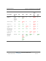
Revision History
Release
2.0 SP1
Date
Documentation Changes
Page No.
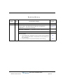
04/11 SERVICE PACK RELEASE
In Chapter 4, “Setting Up the Wave IP 2500 Server”, updated section
“Power supply” and added sections “Minimum configuration”,
“Redundancy”, and “Fault monitoring”.
starting on
page 4-4
Renamed Chapter 9 to “Installing ViewPoint and Other Wave
Workstation Applications” to emphasize ViewPoint installation process.
9-1
Added important note: Do not install ViewPoint on the Wave Server.
9-2
Updated Troubleshooting chapter with symptoms/solutions for the
following issues:
• On a digital phone, password re-entry may fail when forwarding
calls to an external number, because the incorrect password is
not cleared first.
• Firewall problems may prevent ViewPoint from starting.
Wave Server Installation Guide
Release 2.0 Service Pack 1
April 2011
G-6
G-8
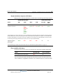
Revision History
Release
Date
2.0
09/10
Documentation Changes
Page No.
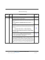
GENERAL RELEASE
Updated Uniform Service Order Code (USOC) table to include new
1-8
All Wave IP 500 Servers now ship with dual (redundant) SATA hard disk
drives configured from the factory which will further increase overall
3-6
VWU-8AT-W and VWU-1T1S-M modules.
reliability.
This new configuration (VW5-IP500-STD2) replaces the single hard
disk drive configuration (VW5-IP500-STD2) which has been
discontinued.
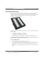
DSS Console devices, associated with a user’s digital phone, provide
“switchboard” capability by expanding the number of extension buttons
available to a digital phone user. See the following sections for more
information:
• “Connecting a DSS Console” on a Wave IP 500 Server
• “Connecting a DSS Console” on a Wave IP 2500 Server
For information about configuring a DSS Console for a user, see section
“Phone dialog \ DSS Consoles tab” in Chapter 4 in the Wave Global
Administrator Guide.
New licenses are required in Wave ISM 2.0.
Wave ISM 2.0 supports scalability and edition-based licensing.
The table of supported Wave license types has been updated with the
new license titles introduced in Wave ISM 2.0.
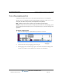
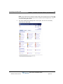
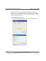
You can now view the status of the licenses on your Wave system by
running the License Status report (in addition to using the Software
Licenses applet). This report reports on all Wave installed licenses by
product name and version, and lists the license key, quantity, type,
status, activation date (blank for a trial license), and expiration date (if
applicable) for each license. For more about using the Report Generator
to run this report, see Chapter 29 in the Wave Global Administrator
Guide.
3-25
4-32
8-2
8-3
8-4
---
Wave Server Installation Guide
Release 2.0 Service Pack 1
April 2011
Revision History
Release
Date
Documentation Changes
Page No.
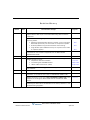
Updated link to Microsoft Download Center to obtain SQL Server 2005
10-5
Express Edition SP2 as part of the Wave Recording Archive Service
installation.
Updated Troubleshooting chapter with symptoms/solutions for the
following issues:
• Pressing a Call Appearance button to answer a call on a 5-series
Aastra SIP phone may not route audio to the phone’s speaker.
• Firewall problems may prevent ViewPoint from starting.
• Long distance prefix added incorrectly on a system with a locale
of “Spanish (Spain)”.
G-5
G-9
G-9
Removed Appendix H, “Wave Software License Agreement”. This
information is now covered in Appendix B in the Wave Global
Administrator Guide.
1.5 SP3
08/09
---
SERVICE PACK RELEASE
Added information on the Quad BRI module. See the following sections:
• “Expansion cards and modules”
• “Connecting the Quad BRI module”
• “About cable connections” (table)
3-7, 4-5
3-23, 4-28
3-15, 4-22
Updated list of Wave license types to reflect support for WaveNet and
8-3
Call Classifier.
1.5 SP2
05/09
SERVICE PACK RELEASE
Updated table in section “Federal Communication Commission (FCC)
statement” to include the new 1-Port T1/PRI Module (VW5-T1-M).
1-8
Added information on the new 1-Port T1/PRI Module (VW5-T1-M) in the
chapters on installing the Wave IP 500 Server and Wave IP 2500
Server.
3-1, 4-1
Added Important note to the procedure documented in section
“Resetting the Wave Server IP addresses to the factory defaults” in the
Troubleshooting Appendix.
G-1
Wave Server Installation Guide
Release 2.0 Service Pack 1
April 2011
Revision History
Release
Date
1.5 SP1
02/09
Documentation Changes
SERVICE PACK RELEASE
The title page and footers have been modified to reflect support for the
current software version. No manual content has changed.
1.5
01/09
Page No.
---
GENERAL RELEASE - IP 500
The Wave IP 500 Server is now supported. Installation instructions for
the Wave IP 500 and Wave IP 2500 are described in separate chapters.
3-1, 4-1
Wave Server Installation Guide
Release 2.0 Service Pack 1
April 2011
Revision History
Release
Date
1.5
11/08
Documentation Changes
Page No.
Added note to the FCC Part 68 compliance statement regarding if a
facility has specially-wired alarm equipment connected to the telephone
line.
1-6
Added section “Physical specifications” listing Wave Server dimensions
and weight.
2-4
GENERAL RELEASE
Added section “About cable connections”, including instructions on
how to connect the 2 types of RJ-21X cables. See Chapter 3 or
Chapter 4, depending on your Wave Server model.
3-15, 4-22
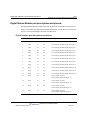
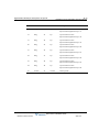
Updated PC requirements sections to include all supported Windows
operating systems.
5-2, 9-3,
10-2
Clarified how an IP address is assigned to the client modem in section
“Connecting to the Wave ISM via a modem.”
5-8
Added a new chapter that explains how to use the Installation Wizard
when setting up a new Wave ISM system.
6-1
Added section “Performing a composite upgrade vs. individual
upgrades.”
7-2
E1 EuroISDN expansion module is now supported. It provides a single
E1 ISDN digital trunk, features an integrated CSU/DSU, and allows
shared data and voice services over a single E1 circuit.
4-27
Expanded section “Adding the Wave Server to your Windows domain”.
Updated “Digital Station Card port descriptions and pinouts” table to
cover both the 12-port and 24-port models.
7-5
B-10
Updated Status LED information.
C-1
Added Expected time column to the System LED tables.
starting on
page C-3
Terminology change: “Redboot boot loader” is now referred to as the
“ISC1 boot loader”.
F-1
Added section “Troubleshooting Management Console problems”.
G-7
Added section “Troubleshooting ViewPoint problems”.
G-8
Added section “Troubleshooting workstation application problems”.
G-10
Wave Server Installation Guide
Release 2.0 Service Pack 1
April 2011
Revision History
Release
Date
1.0 SP2
2/08
Documentation Changes
SERVICE PACK RELEASE
Removed list of supported modems from “Administrator PC
requirements” section. The latest list of client modems certified for use
with Wave Server is available from Wave providers.
5-2
Added note to close and restart browsers on other PCs that had been
running the Global Administrator after restarting the Wave Server.
7-10
Added instructions on how to change the default Locale for non-North
American systems as part of setting basic system information.
7-13
Added section about entering station IDs when installing Wave
workstation applications.
1.0 SP1
12/07
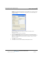
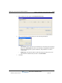
Software Licenses applet: Updated screenshots and procedures to
reflect changes to the Import and Activate processes.
10/07
9-5
SERVICE PACK RELEASE
License activation proxy server section added.
1.0
Page No.
8-16
8-5, 8-10,
8-12
GENERAL RELEASE
Initial Release
---
Wave Server Installation Guide
Release 2.0 Service Pack 1
April 2011
Release 2.0 Service Pack 1
April 2011
Wave Server Installation Guide
Release 2.0 Service Pack 1
April 2011
Contents
Contents
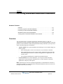
Chapter 1
About This Guide
About Wave ISM - - - - - - - - - - - - - - - - - - - - - - - - - - - - - - - 1-1
Getting the most out of this guide - - - - - - - - - - - - - - - - - - - - - 1-2
Using the Help system - - - - - - - - - - - - - - - - - - - - - - - - - - - - 1-2
Conventions used in this guide - - - - - - - - - - - - - - - - - - - - - - 1-2
Special messages - - - - - - - - - - - - - - - - - - - - - - - - - - - - - - - - - - - - - - - 1-2
Terms used - - - - - - - - - - - - - - - - - - - - - - - - - - - - - - - - - - - - - - - - - - - 1-3
Type conventions - - - - - - - - - - - - - - - - - - - - - - - - - - - - - - - - - - - - - - 1-3
Related reading - - - - - - - - - - - - - - - - - - - - - - - - - - - - - - - - - 1-4
Manuals - - - - - - - - - - - - - - - - - - - - - - - - - - - - - - - - - - - - - - - - - - - - - 1-4
Quick Reference Guides - - - - - - - - - - - - - - - - - - - - - - - - - - - - - - - - - - 1-4
Support services - - - - - - - - - - - - - - - - - - - - - - - - - - - - - - - - 1-5
Corporate Web site - - - - - - - - - - - - - - - - - - - - - - - - - - - - - - 1-5
System security - - - - - - - - - - - - - - - - - - - - - - - - - - - - - - - - - 1-5
Compliance statements - - - - - - - - - - - - - - - - - - - - - - - - - - - - 1-6
Federal Communication Commission (FCC) statement - - - - - - - - - - - - - 1-6
Underwriter’s Laboratory - - - - - - - - - - - - - - - - - - - - - - - - - - - - - - - - - 1-9
Industry Canada - - - - - - - - - - - - - - - - - - - - - - - - - - - - - - - - - - - - - - - 1-9
Wave Server Installation Guide
Release 2.0 Service Pack 1
April 2011
TOC-2
Contents
Chapter 2
Before You Begin
Installation roadmap - - - - - - - - - - - - - - - - - - - - - - - - - - - - - - 2-1
Site preparation - - - - - - - - - - - - - - - - - - - - - - - - - - - - - - - - - 2-3
Physical specifications - - - - - - - - - - - - - - - - - - - - - - - - - - - - - - - - - - - 2-4
Environmental requirements - - - - - - - - - - - - - - - - - - - - - - - - - - - - - - - 2-4
Required tools - - - - - - - - - - - - - - - - - - - - - - - - - - - - - - - - - - - - - - - - - 2-5
Safety requirements - - - - - - - - - - - - - - - - - - - - - - - - - - - - - - 2-6
Protective grounding - - - - - - - - - - - - - - - - - - - - - - - - - - - - - - - - - - - - 2-6
Electrical safety - - - - - - - - - - - - - - - - - - - - - - - - - - - - - - - - - - - - - - - - 2-6
Proper lifting - - - - - - - - - - - - - - - - - - - - - - - - - - - - - - - - - - - - - - - - - - 2-7
Chapter 3
Setting Up the Wave IP 500 Server
About the Wave IP 500 Server - - - - - - - - - - - - - - - - - - - - - - - 3-2
About the Wave IP 500 - - - - - - - - - - - - - - - - - - - - - - - - - - - - - - - - - - - 3-3
Power supply - - - - - - - - - - - - - - - - - - - - - - - - - - - - - - - - - - - - - - - - - 3-5
About the dual SATA hard drives - - - - - - - - - - - - - - - - - - - - - - - - - - - - 3-6
Wave IP 500 expansion options - - - - - - - - - - - - - - - - - - - - - - - - - - - - - 3-6
Mounting the Wave Server - - - - - - - - - - - - - - - - - - - - - - - - - - 3-8
Rack mounting the Wave Server - - - - - - - - - - - - - - - - - - - - - - - - - - - - 3-8
Table mounting the Wave Server - - - - - - - - - - - - - - - - - - - - - - - - - - - - 3-8
Grounding the Wave Server - - - - - - - - - - - - - - - - - - - - - - - - - 3-9
Connecting the Wave Server to power and powering on - - - - - 3-10
Connecting the Wave Server to your LAN - - - - - - - - - - - - - - 3-11
Connecting to trunk and station ports on the ISC2 - - - - - - - - - 3-12
Power failover support - - - - - - - - - - - - - - - - - - - - - - - - - - - - - - - - - - 3-12
Wave Server Installation Guide
Release 2.0 Service Pack 1
April 2011
TOC-3
Contents
Installing expansion components - - - - - - - - - - - - - - - - - - - - 3-13
Installing a Media Resource Module - - - - - - - - - - - - - - - - - - - - - - - - - 3-13
Installing expansion modules - - - - - - - - - - - - - - - - - - - - - - - - - - - - - - 3-13
About connecting modules - - - - - - - - - - - - - - - - - - - - - - - - 3-15
About cable connections - - - - - - - - - - - - - - - - - - - - - - - - - - - - - - - - - 3-15
Connecting an RJ-21X cable - - - - - - - - - - - - - - - - - - - - - - - - - - - - - - 3-16
About connecting specific modules - - - - - - - - - - - - - - - - - - - - - - - - - 3-17
Connecting the analog trunk module - - - - - - - - - - - - - - - - - - 3-18
Connecting the analog universal module - - - - - - - - - - - - - - - 3-18
Connecting the digital station module - - - - - - - - - - - - - - - - - 3-19
Connecting the external power supply for digital phones - - - - - - - - - - - 3-19
Connecting the T1 module with serial interface - - - - - - - - - - 3-20
Connecting the T1 module (without serial interface) - - - - - - - 3-21
Connecting the E1 EuroISDN module with serial interface - - 3-22
Connecting the Quad BRI module - - - - - - - - - - - - - - - - - - - 3-23
Connecting a music-on-hold (MOH) system - - - - - - - - - - - - 3-23
Connecting a paging system - - - - - - - - - - - - - - - - - - - - - - - 3-24
Connecting a DSS Console - - - - - - - - - - - - - - - - - - - - - - - - 3-25
Chapter 4
Setting Up the Wave IP 2500 Server
About the Wave IP 2500 Server - - - - - - - - - - - - - - - - - - - - - - 4-2
About the Wave IP 2500 base unit - - - - - - - - - - - - - - - - - - - - - - - - - - - 4-2
Power supply - - - - - - - - - - - - - - - - - - - - - - - - - - - - - - - - - - - - - - - - - 4-4
Wave Server Installation Guide
Release 2.0 Service Pack 1
April 2011
TOC-4
Contents
Minimum configuration - - - - - - - - - - - - - - - - - - - - - - - - - - - - - - - - - - 4-4
Redundancy - - - - - - - - - - - - - - - - - - - - - - - - - - - - - - - - - - - - - - - - - - 4-4
Fault monitoring - - - - - - - - - - - - - - - - - - - - - - - - - - - - - - - - - - - - - - - 4-4
Wave IP 2500 expansion options - - - - - - - - - - - - - - - - - - - - - - - - - - - - 4-5
Mounting the Wave Server - - - - - - - - - - - - - - - - - - - - - - - - - - 4-7
Rack mounting the Wave Server - - - - - - - - - - - - - - - - - - - - - - - - - - - - 4-7
Wall mounting the Wave Server - - - - - - - - - - - - - - - - - - - - - - - - - - - - - 4-8
Table mounting the Wave Server - - - - - - - - - - - - - - - - - - - - - - - - - - - 4-11
Grounding the Wave Server - - - - - - - - - - - - - - - - - - - - - - - - 4-12
Connecting the Wave Server to power and powering on - - - - - 4-13
Connecting the Wave Server to your LAN - - - - - - - - - - - - - - 4-14
About the Ethernet ports on the Wave Server - - - - - - - - - - - - - - - - - - - 4-14
Connecting to trunk and station ports on the ISC1 - - - - - - - - - 4-15
Power failover support - - - - - - - - - - - - - - - - - - - - - - - - - - - - - - - - - - 4-16
Installing expansion components - - - - - - - - - - - - - - - - - - - - - 4-16
Installing EXUs on a Wave Server - - - - - - - - - - - - - - - - - - - - - - - - - - 4-17
Installing a Media Resource Module - - - - - - - - - - - - - - - - - - - - - - - - - 4-18
Installing expansion modules and cards - - - - - - - - - - - - - - - - - - - - - - - 4-20
About connecting modules and cards - - - - - - - - - - - - - - - - - - 4-21
About cable connections - - - - - - - - - - - - - - - - - - - - - - - - - - - - - - - - - 4-22
Connecting an RJ-21X cable - - - - - - - - - - - - - - - - - - - - - - - - - - - - - - 4-22
About connecting specific modules and cards - - - - - - - - - - - - - - - - - - - 4-24
Connecting the analog trunk module - - - - - - - - - - - - - - - - - - 4-24
Connecting the analog universal module - - - - - - - - - - - - - - - 4-25
Connecting the digital station module - - - - - - - - - - - - - - - - - 4-25
Wave Server Installation Guide
Release 2.0 Service Pack 1
April 2011
TOC-5
Contents
Connecting the T1 module with serial interface - - - - - - - - - - 4-26
Connecting the T1 module (without serial interface) - - - - - - - 4-27
Connecting the E1 EuroISDN module with serial interface - - 4-27
Connecting the Quad BRI module - - - - - - - - - - - - - - - - - - - 4-28
Connecting the analog station card - - - - - - - - - - - - - - - - - - - 4-29
Connecting the digital station card - - - - - - - - - - - - - - - - - - - 4-29
Connecting a music-on-hold (MOH) system - - - - - - - - - - - - 4-30
Connecting a paging system - - - - - - - - - - - - - - - - - - - - - - - 4-31
Connecting a DSS Console - - - - - - - - - - - - - - - - - - - - - - - - 4-32
Chapter 5
Connecting to the Wave ISM from the administrator PC
Obtaining all required HotFixes - - - - - - - - - - - - - - - - - - - - - - 5-1
Administrator PC requirements - - - - - - - - - - - - - - - - - - - - - - 5-2
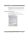
Configuring the administrator PC - - - - - - - - - - - - - - - - - - - - - 5-3
Connecting to the Wave ISM - - - - - - - - - - - - - - - - - - - - - - - - 5-4
Connecting to the Wave ISM via your network - - - - - - - - - - - - - - - - - - 5-5
Connecting to the Wave ISM via a modem - - - - - - - - - - - - - - - - - - - - - 5-8
Chapter 6
Using the Wave Installation Wizard
About the Wave Installation Wizard - - - - - - - - - - - - - - - - - - - 6-1
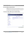
Running the Wave Installation Wizard - - - - - - - - - - - - - - - - - 6-2
Configuring the Wave ISM using the Installation Wizard - - - - - 6-2
Wave Server Installation Guide
Release 2.0 Service Pack 1
April 2011
TOC-6
Contents
Chapter 7
Initial Configuration
Applying HotFixes - - - - - - - - - - - - - - - - - - - - - - - - - - - - - - - 7-1
Issues that can prevent or affect an upgrade - - - - - - - - - - - - - - - - - - - - - 7-2
Performing a composite upgrade vs. individual upgrades - - - - - - - - - - - - 7-2
Identifying the Wave Server on your LAN - - - - - - - - - - - - - - - 7-4
Changing the default IP network settings on the Wave Server - - - - - - - - - 7-4
Configuring the Wave Server for one-click license activation - - - - - - - - - 7-5
Adding the Wave Server to your Windows domain - - - - - - - - - - - - - - - - 7-5
Changing the default host name of the Wave Server - - - - - - - - - - - - - - - 7-6
Power-cycling the Wave Server - - - - - - - - - - - - - - - - - - - - - 7-10
Setting the dial-in default IP address pool - - - - - - - - - - - - - - - 7-11
Performing basic system configuration tasks - - - - - - - - - - - - - 7-13
Entering basic system information - - - - - - - - - - - - - - - - - - - - - - - - - - 7-13
Setting the system date and time - - - - - - - - - - - - - - - - - - - - - - - - - - - 7-17
Configuring the time service used by Wave ISM - - - - - - - - - - - - - - - - 7-18
Adding Wave ISM user and administrator accounts - - - - - - - - 7-19
Adding Wave ISM user accounts and passwords - - - - - - - - - - - - - - - - 7-19
Creating Wave ISM administrator accounts on the primary domain controller
7-21
Using accounts from a trusted domain - - - - - - - - - - - - - - - - - - - - - - - - 7-23
Installing client caching to improve Global Administrator
performance - - - - - - - - - - - - - - - - - - - - - - - - - - - - - - - - - - - 7-25
Verifying installed hardware components - - - - - - - - - - - - - - - 7-25
Wave Server Installation Guide
Release 2.0 Service Pack 1
April 2011
TOC-7
Contents
Chapter 8
Entering and Activating Wave Licenses
About Wave licenses - - - - - - - - - - - - - - - - - - - - - - - - - - - - - 8-1
New licenses are required in Wave ISM 2.0. - - - - - - - - - - - - - - - - - - - 8-2
Full vs. trial licenses - - - - - - - - - - - - - - - - - - - - - - - - - - - - - - - - - - - - 8-2
Obtaining Wave licenses - - - - - - - - - - - - - - - - - - - - - - - - - - - - - - - - - 8-2
Wave license requirements - - - - - - - - - - - - - - - - - - - - - - - - - - - - - - - - 8-3
Entering Wave licenses - - - - - - - - - - - - - - - - - - - - - - - - - - - 8-5
Entering Wave licenses by importing a license file - - - - - - - - - - - - - - - - 8-5
Entering Wave license keys for each license - - - - - - - - - - - - - - - - - - - - 8-7
Activating Wave licenses - - - - - - - - - - - - - - - - - - - - - - - - - - 8-8
Before your licenses are activated - - - - - - - - - - - - - - - - - - - - - - - - - - - 8-8
The activation process - - - - - - - - - - - - - - - - - - - - - - - - - - - - - - - - - - - 8-9
Activating your Wave licenses using one-click activation - - - - - - - - - - 8-10
Activating your licenses using offline activation - - - - - - - - - - - - - - - - - 8-12
Configuring the Wave ISM to save rather than open License files - - - - - 8-16
Setting up a proxy server for license activation - - - - - - - - - - - 8-16
Viewing the status of licenses on your system - - - - - - - - - - - 8-18
Chapter 9
Installing ViewPoint and Other Wave Workstation
Applications
About the Wave workstation applications - - - - - - - - - - - - - - - 9-1
Attended vs. unattended installs - - - - - - - - - - - - - - - - - - - - - - - - - - - - - 9-2
About auto-upgrading - - - - - - - - - - - - - - - - - - - - - - - - - - - - - - - - - - - 9-2
Requirements - - - - - - - - - - - - - - - - - - - - - - - - - - - - - - - - - - 9-2
Where to install the Wave workstation applications - - - - - - - - - - - - - - - 9-2
Do not install ViewPoint on the Wave Server! - - - - - - - - - - - - - - - - - - - 9-2
Wave Server Installation Guide
Release 2.0 Service Pack 1
April 2011
TOC-8
Contents
ViewPoint requirements - - - - - - - - - - - - - - - - - - - - - - - - - - - - - - - - - - 9-3
TAPI Service Provider and Contact Manager Assistant requirements - - - - 9-4
Archived Recording Browser requirements - - - - - - - - - - - - - - - - - - - - - 9-5
Using the Wave Workstation Applications Setup - - - - - - - - - - - 9-5
Entering station IDs - - - - - - - - - - - - - - - - - - - - - - - - - - - - - - - - - - - - - 9-5
Configuring the Wave workstation applications - - - - - - - - - - - - 9-9
Configuring ViewPoint - - - - - - - - - - - - - - - - - - - - - - - - - - - - - - - - - - - 9-9
Configuring the TAPI Service Provider - - - - - - - - - - - - - - - - - - - - - - - - 9-9
Configuring the Wave Contact Manager Assistant - - - - - - - - - - - - - - - 9-10
Configuring the Archived Recording Browser - - - - - - - - - - - - - - - - - - 9-10
Synchronizing system clocks - - - - - - - - - - - - - - - - - - - - - - - 9-11
Chapter 10
Installing the Wave Recording Archive Service
About archiving mailbox recordings - - - - - - - - - - - - - - - - - - 10-1
Requirements - - - - - - - - - - - - - - - - - - - - - - - - - - - - - - - - - - 10-2
Archive server PC requirements - - - - - - - - - - - - - - - - - - - - - - - - - - - - 10-2
Archive folder requirements - - - - - - - - - - - - - - - - - - - - - - - - - - - - - - 10-3
Installation steps - - - - - - - - - - - - - - - - - - - - - - - - - - - - - - - - 10-4
Appendix A
Using Wave Workstation Applications with Microsoft
Terminal Services or Citrix MetaFrame
Overview - - - - - - - - - - - - - - - - - - - - - - - - - - - - - - - - - - - - A-1
Installing workstation applications on an application server - - - A-2
Installing workstation applications on a Windows 2003 server - - - - - - - A-2
Wave Server Installation Guide
Release 2.0 Service Pack 1
April 2011
TOC-9
Contents
Appendix B
Trunk and Station Ports and Pinouts
Integrated Services Card (ISC1) port descriptions and pinouts - B-1
RJ-21X interface port descriptions and pinouts - - - - - - - - - - - - - - - - - - B-1
Integrated Services Card (ISC2) port descriptions and pinouts - B-2
RJ-11 interface port descriptions and pinouts - - - - - - - - - - - - - - - - - - - B-2
Analog Universal Module port descriptions and pinouts - - - - - B-4
RJ-21X interface port descriptions and pinouts - - - - - - - - - - - - - - - - - - B-4
Analog Trunk Module port descriptions and pinouts - - - - - - - - B-5
RJ-21X interface port descriptions and pinouts - - - - - - - - - - - - - - - - - - B-5
T1 Module with serial interface pinouts - - - - - - - - - - - - - - - - B-5
RJ-48X interface pinouts - - - - - - - - - - - - - - - - - - - - - - - - - - - - - - - - B-5
DB-60 interface pinouts - - - - - - - - - - - - - - - - - - - - - - - - - - - - - - - - - B-6
T1 Module (without serial interface) pinouts - - - - - - - - - - - - - B-7
RJ-48X interface pinouts - - - - - - - - - - - - - - - - - - - - - - - - - - - - - - - - B-7
E1 Module with serial interface port descriptions and pinouts - - B-7
Analog Station Card port descriptions and pinouts - - - - - - - - - B-9
RJ-21X interface port descriptions and pinouts - - - - - - - - - - - - - - - - - - B-9
Digital Station Card port descriptions and pinouts - - - - - - - - - B-10
RJ-21X interface port descriptions and pinouts - - - - - - - - - - - - - - - - - - B-10
Digital Station Module port descriptions and pinouts - - - - - - B-12
RJ-21X interface port descriptions and pinouts - - - - - - - - - - - - - - - - - - B-12
Appendix C
Integrated Services Card Status LEDs
Overview - - - - - - - - - - - - - - - - - - - - - - - - - - - - - - - - - - - - - C-1
Wave Server Installation Guide
Release 2.0 Service Pack 1
April 2011
TOC-10
Contents
About Card LEDs - - - - - - - - - - - - - - - - - - - - - - - - - - - - - - - - - - - - - C-1
About System Status LEDs - - - - - - - - - - - - - - - - - - - - - - - - - - - - - - - C-2
Acronyms and definitions of selected terms - - - - - - - - - - - - - - - - - - - - C-2
System LED indicators - - - - - - - - - - - - - - - - - - - - - - - - - - - C-3
Normal boot sequence indicators - - - - - - - - - - - - - - - - - - - - - - - - - - - C-3
System shutdown sequence indicators - - - - - - - - - - - - - - - - - - - - - - - - C-6
Error condition indicators - - - - - - - - - - - - - - - - - - - - - - - - - - - - - - - - C-6
Appendix D
Performing Unattended Workstation Installations
Overview - - - - - - - - - - - - - - - - - - - - - - - - - - - - - - - - - - - - D-1
Performing a typical unattended installation - - - - - - - - - - - - - D-2
Performing a custom unattended installation - - - - - - - - - - - - - D-2
Custom unattended installation examples - - - - - - - - - - - - - - - - - - - - - D-2
Workstation Setup command parameters - - - - - - - - - - - - - - - D-3
Verifying that an unattended installation was successful - - - - - D-7
Appendix E
Configuring Wave ISM for the Windows Firewall
Overview - - - - - - - - - - - - - - - - - - - - - - - - - - - - - - - - - - - - - E-1
About Wave ISM and the Windows Firewall - - - - - - - - - - - - - E-1
Adjusting Windows Firewall exceptions - - - - - - - - - - - - - - - - - E-2
How updated Windows Firewall exceptions are applied - - - - - - - - - - - - E-3
Windows Firewall exceptions added for Wave - - - - - - - - - - - - E-4
Wave Server Installation Guide
Release 2.0 Service Pack 1
April 2011
TOC-11
Contents
Appendix F
Upgrading the ISC1/ISC2 boot loader
Overview - - - - - - - - - - - - - - - - - - - - - - - - - - - - - - - - - - - - - F-1
Before you begin - - - - - - - - - - - - - - - - - - - - - - - - - - - - - - - - F-2
Upgrading the ISC1/ISC2 boot loader - - - - - - - - - - - - - - - - - - F-2
Appendix G
Troubleshooting
General troubleshooting steps - - - - - - - - - - - - - - - - - - - - - - - G-1
Troubleshooting modem problems - - - - - - - - - - - - - - - - - - - - G-3
Troubleshooting IP telephony problems - - - - - - - - - - - - - - - - G-5
Troubleshooting phone problems - - - - - - - - - - - - - - - - - - - - - G-5
Troubleshooting SIP phone problems - - - - - - - - - - - - - - - - - - - - - - - - G-5
Troubleshooting digital phone problems - - - - - - - - - - - - - - - - - - - - - - G-6
Troubleshooting Management Console problems - - - - - - - - - - G-7
Troubleshooting ViewPoint problems - - - - - - - - - - - - - - - - - - G-8
Troubleshooting workstation application problems - - - - - - - - G-10
Index
Wave Server Installation Guide
Release 2.0 Service Pack 1
April 2011
Release 2.0 Service Pack 1
April 2011
Chapter 1
About This Guide
CHAPTER CONTENTS
About Wave ISM . . . . . . . . . . . . . . . . . . . . . . . . . . . . . . . . . . . . . . . . . . . . . . . . 1-1
Getting the most out of this guide . . . . . . . . . . . . . . . . . . . . . . . . . . . . . . . . . . . 1-2
Using the Help system . . . . . . . . . . . . . . . . . . . . . . . . . . . . . . . . . . . . . . . . . . . . 1-2
Conventions used in this guide . . . . . . . . . . . . . . . . . . . . . . . . . . . . . . . . . . . . . 1-2
Related reading . . . . . . . . . . . . . . . . . . . . . . . . . . . . . . . . . . . . . . . . . . . . . . . . . 1-4
Support services . . . . . . . . . . . . . . . . . . . . . . . . . . . . . . . . . . . . . . . . . . . . . . . . 1-5
Corporate Web site . . . . . . . . . . . . . . . . . . . . . . . . . . . . . . . . . . . . . . . . . . . . . . 1-5
System security . . . . . . . . . . . . . . . . . . . . . . . . . . . . . . . . . . . . . . . . . . . . . . . . . 1-5
Compliance statements . . . . . . . . . . . . . . . . . . . . . . . . . . . . . . . . . . . . . . . . . . . 1-6
About Wave ISM
Welcome to Wave ISM—a unified platform designed for scalability, reliability, and ease of use
that delivers comprehensive communication support, including PBX voice capability,
multiprotocol router capabilities, full LAN/WAN connectivity, and a suite of communication
applications.
Wave Server Installation Guide
Release 2.0 Service Pack 1
April 2011
1-2
Chapter 1: About This Guide
Getting the most out of this guide
Getting the most out of this guide
This guide provides detailed instructions for installing the Wave Server and Wave ISM and
performing initial system configuration. See “Installation roadmap” on page 2-1 for details on
the required and optional installation steps.
Note how the following terms are used in this guide:
•
“Wave ISM” refers to the Wave software infrastructure, Wave Integrated Services
Manager.
•
“Wave Server” refers to the physical server PC on which Wave ISM runs. Most of the
information in this guide applies to all Wave Server models. When information applies to
a specific Wave Server model, the model is identified, for example “Wave IP 2500” or
“Wave IP 500”.
•
•
For more about the Wave IP 500, see Chapter 3.
•
For more about the Wave IP 2500, see Chapter 4.
“The Wave ISM” refers to your Wave phone system as a whole.
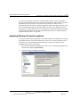
Using the Help system
The Wave ISM Help system provides both online and context-sensitive Help. To access each
type of Help, use the following methods:
•
Online Help—From the Wave Global Administrator Management Console, press the
Help icon located in the top right corner of the screen, then select a topic from either the
Contents tab or the Index tab.
•
Context-sensitive Help—From each Global Administrator Management Console applet
or dialog where you see a Help button, click it to directly access the relevant Help topic.
Conventions used in this guide
In the course of describing product features and functions, this guide uses the conventions
described in this section.
Special messages
Note: A note expands on information in the text.
Hint: A hint suggests a way to work smarter or helps you perform a task.
Wave Server Installation Guide
Release 2.0 Service Pack 1
April 2011
1-3
Chapter 1: About This Guide
Conventions used in this guide
Important: An Important note relays information that is of special interest.
Caution: A caution highlights information that helps you prevent damage to the equipment or
to data, and tells you how to avoid the problem.
Warning: A warning alerts you to a situation that could cause you physical harm.
Terms used
Term
How to Interact
Click
Click the left mouse button.
Right-click
Click the right mouse button.
Shift-click
Hold down the Shift key, and simultaneously click the left mouse
button.
Ctrl-click
Hold down the Ctrl key, and simultaneously click the left mouse
button.
Ctrl+another key
Hold down the Ctrl key, and simultaneously press one or more
additional keys, for example Ctrl+Q.
Enter
Press the Enter key, or click OK.
Type
Type the indicated text, but do not press the Enter key or click OK
until you are directed to do so.
Press
Press the indicated key or keys.
Check
Place a check mark in the check box.
Select
Choose an option from a menu, drop-down list, or list of radio
buttons.
Type conventions
Type Convention
Used to Indicate
italics
Book titles, variables, and word emphasis
courier font
Screen text and user-typed command line entries
Initial Caps
Menu titles, window names, button names, file names, and
directories
Wave Server Installation Guide
Release 2.0 Service Pack 1
April 2011
1-4
Chapter 1: About This Guide
Related reading
Related reading
For information about this version of Wave ISM, including new features, known issues, and
other late-breaking information, see the Release Notes included on the Documentation CD.
The following additional documents are included with the Wave Server in Acrobat format, and
can be found on the Documentation CD.
Manuals
Wave ISM System Recovery Guide—Describes how to use the Wave ISM System Recovery
Disk or System Recovery USB Thumbdrive to restore your Wave Server to its original factory
settings for emergency recovery.
Wave Global Administrator Guide—Task-based instructions on how to use all aspects of the
Wave Global Administrator Management Console.
Wave ViewPoint User Guide—Task-based instructions on how to use ViewPoint, including call
control, working from remote locations, participating in a contact center, and so forth.
Wave Phone User Guide—Describes how to use SIP phones, digital phones, analog phones,
and SIP softphones with Wave.
Wave Server Hardware Reference Guide—Detailed technical information about the Wave
Server hardware components.
Quick Reference Guides
Wave Analog Phone Quick Reference Guide—Instructions for using analog phones with
Wave.
Wave Digital Phone Quick Reference Guide—Instructions for using digital phones with Wave.
Wave SIP Phone Quick Reference Guide—Instructions for using SIP phones with Wave.
Wave Voice Mail Quick Reference Guide—Instructions for using Wave ISM Voice Mail
features.
Wave Server Installation Guide
Release 2.0 Service Pack 1
April 2011
1-5
Chapter 1: About This Guide
Support services
Support services
Vertical Communications, Inc. has worked diligently to produce the highest quality
communications system possible. In the course of installing or customizing a system, however,
customers may require personal attention.
For technical support, contact your Vertical Wave provider.
Corporate Web site
For more information about Vertical Communications, Inc. and the Vertical Wave product line,
contact your Vertical Wave provider, call 1-877-VERTICAL, or visit the Vertical corporate Web
site:
http://www.vertical.com
System security
You are responsible for the security of your Vertical Wave system. Unauthorized use of the
Vertical Wave system could result in toll fraud. You must read all system administration
documentation to understand which configuration options can introduce the risk of toll fraud,
and which configuration options can be activated or deactivated to prevent fraud.
For more information, see Appendix A, “Protecting your Phone System Against Toll Fraud” in
the Wave Global Administrator Guide.
Note: Vertical Communications, Inc. does not warrant that the configuration software is
immune from or will prevent unauthorized use of common-carrier telecommunications facilities
and services accessed through or connected to the Wave Server. Vertical Communications, Inc.
is not responsible for any charges that could result from unauthorized use.
Wave Server Installation Guide
Release 2.0 Service Pack 1
April 2011
1-6
Chapter 1: About This Guide
Compliance statements
Compliance statements
Federal Communication Commission (FCC) statement
The following statements are provided in accordance with the Federal Communications
Commission (FCC) regulations. Please read these statements carefully before installing your
system.
FCC Part 15
This device complies with Part 15 of the FCC rules. Operation is subject to the following two
conditions: (1) This device may not cause harmful interference, and (2) this device must accept
any interference received, including interference that may cause undesired operation.
Changes or modifications not expressly approved by Vertical Communications, Inc. could void
your authority to operate the equipment.
Note: This equipment has been tested and found to comply with the limits for a Class A digital
device, pursuant to Part 15 of the FCC rules. These limits are designed to provide reasonable
protection against harmful interference when the equipment is operated in a commercial
environment. This equipment generates, uses, and can radiate radio frequency energy and, if not
installed and used in accordance with the instruction manual, may cause harmful interference to
radio communications. Operation of this equipment in a residential area is likely to cause
harmful interference in which case the user will be required to correct the interference at his own
expense.
FCC Part 68
This equipment complies with Part 68 of the FCC rules. Located on the equipment is a label that
contains, among other information, the FCC registration number and Ringer Equivalence
Number (REN). If requested, this information must be provided to the telephone company.
The REN is used to determine the quantity of devices which may be connected to the telephone
line. Excessive RENs on the telephone line may result in the devices not ringing in response to
an incoming call. In most but not all areas, the sum of the RENs should not exceed five (5.0).
To be certain of the number of devices that may be connected to the line, as determined by the
total RENs, contact the telephone company to determine the maximum REN for the calling area.
This equipment cannot be used on the telephone company-provided coin service. Connection to
Party Line Service is subject to State tariffs.
Wave Server Installation Guide
Release 2.0 Service Pack 1
April 2011
1-7
Chapter 1: About This Guide
Compliance statements
If this equipment causes harm to the telephone network, the telephone company will notify you
in advance that temporary discontinuance of service may be required. If advance notice isn’t
practical, the telephone company will notify the customer as soon as possible. Also, you will be
advised of your right to file a complaint with the FCC if you believe it is necessary.
The telephone company may make changes in its facilities, equipment, operations or procedures
that could affect the operation of the equipment. If this happens, the telephone company will
provide advance notice in order for you to make the necessary modifications in order to
maintain uninterrupted service.
If problems are experienced with this equipment, please contact your reseller.
If the problem is causing harm to the telephone network, the telephone company may require
you to remove the equipment from the network until the problem is resolved.
It is recommended that the customer install an AC surge arrester in the AC outlet to which this
device is connected. This is to avoid damaging the equipment caused by local lightening strikes
and other electrical surges.
If your facility has specially wired alarm equipment connected to the telephone line, ensure the
installation of Vertical equipment does not disable your alarm equipment. If you have questions
about what will disable alarm equipment, consult your telephone company or a qualified
installer.
This equipment is Hearing-Aid Compatible (HAC).
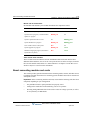
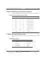
Wave Server models
The following table lists the FCC registration number and REN for each supported Wave Server
model.
Wave Server
FCC registration number
REN
Wave IP 2500
6F-USA-33307-PF-E
0.9
Wave IP 500
6F-JUSA-33307-PF-E
0.9
Wave Server Installation Guide
Release 2.0 Service Pack 1
April 2011
1-8
Chapter 1: About This Guide
Compliance statements
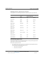
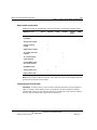
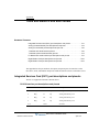
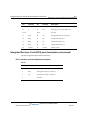
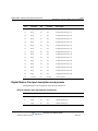
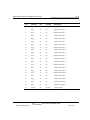
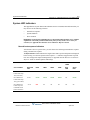
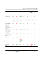
Embedded processors, expansion cards, and modules
This equipment uses the following Uniform Service Order Code (USOC) jacks and codes:
Model Name
Facility Interface
Code
REN or
Jack Type
Service Order Code
VWU-8AT-M
02LS2
0.2B
RJ-21X
VWU-8AT-M
02GS2
0.2B
RJ-21X
VW-IS1-C
02LS2
0.2B
RJ-21X
VW5-IS2-C
02LS2
0.2B
RJ-11
VWU-1T1S-M,
VW5-T1-M
04DU9-BN
6.0Y
RJ-48C
VWU-1T1S-M,
VW5-T1-M
04DU9-DN
6.0Y
RJ-48C
VWU-1T1S-M,
VW5-T1-M
04DU9-1KN
6.0Y
RJ-48C
VWU-1T1S-M,
VW5-T1-M
04DU9-1SN
6.0Y
RJ-48C
VWU-1T1S-M,
VW5-T1-M
04DU9-1SN (PRI)
6.0Y
RJ-48C
VWU-8x8AU-M
02LS2
0.2B
RJ-21X
VWU-8x8AU-M
02GS2
0.2B
RJ-21X
VWU-8x8AU-M
02RV2-T
AS.2
RJ-21X
Direct Inward Dialing (DID) interfaces
Allowing this equipment to be operated in such a manner as to not provide for proper answer
supervision is a violation of Part 68 of the FCC rules.
Proper answer supervision is when:
•
The equipment returns answer supervision to the Public Switched Telephone Network
(PSTN) when Direct Inward Dialing (DID) calls are:
•
Answered by the called station
•
Answered by the attendant
Wave Server Installation Guide
Release 2.0 Service Pack 1
April 2011
1-9
Chapter 1: About This Guide
Compliance statements
•
•
Routed to a recorded announcement that can be administered by the Customer
Premise Equipment (CPE) user
The equipment returns answer supervision on all DID calls forwarded to the PSTN.
Permissible exceptions are:
•
A call is unanswered
•
A busy tone is received
•
A reorder tone is received
Underwriter’s Laboratory
Underwriter’s Laboratory (UL) & Canadian Underwriter’s Laboratory (CUL)
This equipment is Safety Listed by MET Laboratories, Baltimore, Maryland and complies with
Underwriters Laboratories Standard UL 60950-1 (USA) and CSA C22.2 No. 60950-1. MET
Laboratories may be contacted at 800-638-6057 or www.metlabs.com.
To reduce the risk of fire: use 26 AWG line cords that have been evaluated as Communication
Circuit Accessories, UL 1863, for all telephone connections. This statement applies to all cards
and modules that connect to telephones or the Public Switched Telephone Network (PSTN).
Industry Canada
This section describes the requirements for end users in accordance with CS-03.
The Industry Canada label identifies certified equipment. This certification means that the
equipment meets certain telecommunications network protective, operational and safety
requirements as prescribed in the appropriate Terminal Equipment Technical Requirements
documents. The Department does not guarantee the equipment will operate to the user’s
satisfaction.
Before installing this equipment, users should ensure that it is permissible to be connected to the
facilities of the local telecommunications company. The equipment must also be installed using
an acceptable method of connection. The customer should be aware that compliance with the
above conditions may not prevent degradation of service in certain situations
Repairs to certified equipment should be coordinated by a representative designated by the
supplier. Any repairs or alterations made by the user to this equipment, or equipment
malfunctions, may give the telecommunications company cause to request the user disconnect
the equipment.
Wave Server Installation Guide
Release 2.0 Service Pack 1
April 2011
1-10
Chapter 1: About This Guide
Compliance statements
Users should ensure for their own protection that the electrical ground connections of the power
utility, telephone lines, and internal metallic water pipe system, if present, are connected
together. This precaution may be particularly important in rural areas.
Users should not attempt to make such connections themselves, but should contact the
appropriate electric inspection authority, or electrician, as appropriate.
The Ringer Equivalence Number (REN) for each device (card or module) is listed in the
appropriate chapter.
The standard connecting arrangement (telephone jack type) for each card or module is listed in
the appropriate chapter.
Wave Server Installation Guide
Release 2.0 Service Pack 1
April 2011
Chapter 2
Before You Begin
CHAPTER CONTENTS
Installation roadmap . . . . . . . . . . . . . . . . . . . . . . . . . . . . . . . . . . . . . . . . . . . . . . 2-1
Site preparation . . . . . . . . . . . . . . . . . . . . . . . . . . . . . . . . . . . . . . . . . . . . . . . . . 2-3
Safety requirements . . . . . . . . . . . . . . . . . . . . . . . . . . . . . . . . . . . . . . . . . . . . . . 2-6
Installation roadmap
You must perform the tasks listed in the following table in the order specified. This list is only
an overview of the tasks you must perform. Detailed instructions for each task are presented in
the indicated chapters.
Important: All steps are required unless otherwise noted.
Step
Description
1
Read the Release Notes for important late-breaking information
about this version of Wave ISM, including installation tips, known
issues and workarounds.
Documentation
CD included
with Wave ISM
2
Prepare the site where the Wave Server will be installed.
This chapter
3
Install the Wave Server. Tasks include mounting and grounding
Chapter 3
(Wave IP 500)
or
procedures; connecting the Wave Server to power and to your
LAN; connecting to your service provider’s voice or data trunks;
connecting digital and analog phones; installing and connecting
expansion components if you are using them; and connecting a
music-on-hold (MOH) system and/or paging system.
See
Chapter 4
(Wave IP 2500)
Wave Server Installation Guide
Release 2.0 Service Pack 1
April 2011
2-2
Chapter 2: Before You Begin
Installation roadmap
Step
Description
See
4
Configure and connect the administrator PC. Tasks include
configuring TCP/IP on the PC that you will use to administer
Wave ISM, connecting to the Wave ISM via your LAN or a
modem, installing client caching to improve performance, and
verifying installed hardware components.
Chapter 5
5
For new Wave ISM systems only: Configure your system via the
Installation Wizard. If you are upgrading an existing system, you
Chapter 6
cannot use the Installation Wizard
6
Set up the Wave Server for initial configuration. Tasks include
Chapter 7
obtaining and applying all required HotFixes; identifying the
Wave Server on your LAN; power-cycling the Wave Server;
setting the dial-in default IP address pool; performing basic system
configuration tasks, including entering information about your
system, setting the system date and time, and configuring the time
service used by Wave ISM; and adding Wave ISM user and
administrator accounts.
7
Enter and activate your Wave licenses to enable full system
Chapter 8
functionality.
8
Optionally, install ViewPoint and other Wave workstation
applications on the PCs of users who need to run them: ViewPoint,
Chapter 9
TAPI Service Provider, Contact Manager Assistant, and Archived
Recording Browser. (See Appendix A if you plan to install the
workstation applications on an applications server running on
Microsoft Terminal Services or Citrix® MetaFrame.)
9
10
Optionally, install the Wave Recording Archive Service to allow
users to search for and manage archived recordings using the
Wave Archived Recording Browser.
Chapter 10
Optionally, configure the Windows firewall for the Wave
workstation applications. If you installed the Wave workstation
Appendix E
applications or Wave Recording Archive service, this appendix applies to
you.
11
Optionally, upgrade the ISC boot loader if necessary. Note that
Appendix F
you do not need to upgrade the ISC boot loader if you are installing
Wave ISM on a new Wave Server for the first time.
Wave Server Installation Guide
Release 2.0 Service Pack 1
April 2011
2-3
Chapter 2: Before You Begin
Site preparation
Where to go next
After you complete the tasks described in this manual, your Wave ISM is fully operational. You
are now ready to configure and customize your phone system, for example:
•
Set system-wide Wave ISM options, such as business hours and holidays, voice mail
options, password security to prevent toll fraud, and so forth.
•
Connect and configure analog and digital trunks and stations.
•
Set up IP telephony.
•
Configure your dial plan, inbound and outbound call routing, hunt groups, and so forth.
•
Add and configure users, roles, and workgroups.
•
Set up auto attendants.
Note: If you used the Installation Wizard as described in Chapter 6, you may already have
performed some or all of these tasks.
For more information on these topics and more, see the Wave Global Administrator Guide. The
Wave Global Administrator Guide includes information for readers at a variety of levels. To get
the most out of the documentation, start by reading the parts that are most relevant to your level
of experience. See “Where to start” in Chapter 1 for more information.
Site preparation
It is important to set up your site properly before installing the Wave Server. Before removing
the Wave Server from the packing material do the following:
•
Determine the location where the Wave Server will reside. The Wave Server requires a
dust-free location with heating, air conditioning, and ventilation. See “Environmental
requirements” on page 2-4.
•
Install all punchdown blocks and patch panels.
•
Purchase and install an EIA- or IEC-compliant, 19-inch equipment rack, if you plan to
rack mount the Wave Server.
•
Install TIA/EIA-568A standard cabling (for example, Category 3 for voice, or Category 5
for voice and data.)
Caution: An Uninterruptible Power Supply (UPS) is strongly recommended in case of a site
power failure. See Appendix C in the Wave Server Hardware Reference Guide for
specifications.
Wave Server Installation Guide
Release 2.0 Service Pack 1
April 2011
2-4
Chapter 2: Before You Begin
Site preparation
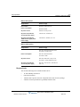
Physical specifications
Wave IP 500
Dimensions
2.6 inches high x 17.6 wide x 13.8 inches deep (6.4 x 44.7 x 34.9 cm), 1.5U
rack height)
Weight
14 pounds (6.4 kg)
Wave IP 2500
Dimensions
Base unit: 4.4 inches high x 17.6 wide x 17.9 deep (11.1 x 44.7 x 45.5 cm),
2.5U rack height
EXU: 2.6 inches high x 17.6 wide x 17.9 deep (6.4 x 44.7 x 45.5 cm),
1.5U rack height
Weight
Base unit: 26 pounds (11.8 kg)
EXU: 19 pounds (8.6 kg)
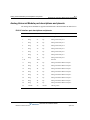
Environmental requirements
For the Wave Server to operate properly, the environmental specifications in the following table
must be met
All models.
Requirement
Value or range
Operating temperature
32° to 104° F (0° to 40° C)
Operating humidity
80% maximum relative humidity, noncondensing
Operating altitude
Up to 10,000 ft (3050 m)
Storage temperature
-4° to 140° F (-20° to 60° C)
Storage humidity
85% maximum relative humidity, noncondensing
Clearance for servicing
Minimum 24 in (61 cm) front and back
Clearance for cooling
Minimum 4 in (10 cm) on all sides
AC power requirements,
E1 internal power supply
Base unit: 100-240 VAC, 50/60 Hz, 9A
EXU: 6A
Wave Server Installation Guide
Release 2.0 Service Pack 1
April 2011
2-5
Chapter 2: Before You Begin
Site preparation
Wave IP 500-specific.
Requirement
Value or range
Heat emitted
Maximum 1980 BTU/hour
Power consumption
Maximum 580W
AC power source
Dedicated 15-amp circuit
AC power requirements,
T1 internal power supply
100-240 VAC, 50/60 Hz, 9A
AC power requirements,
180W external digital phone
power supply
100-240VAC, 50/60Hz, 2.4-1.2A
Wave IP 2500-specific.
Requirement
Value or range
Heat emitted
Base unit: Maximum 2830 BTU/hour
Each EXU: 910 BTU/hour
Power consumption
Base unit: Maximum 830W
Each EXU: 560W
AC power source
Base unit: Dedicated 15-amp circuit
Each EXU: 10-amp dedicated circuit
AC power requirements,
T1 internal power supply
Base unit: 100-120 VAC, 50/60 Hz, 9A
EXU: 6A
Required tools
You need the following tools to install the Wave Server:
•
#1 and #2 Phillips screwdriver
•
Flat-head screwdriver
•
Antistatic mat to protect electronic components from static electricity damage
•
Antistatic wrist strap attached to a grounded, antistatic leash
Wave Server Installation Guide
Release 2.0 Service Pack 1
April 2011
2-6
Chapter 2: Before You Begin
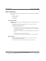
Safety requirements
Safety requirements
Refer to the following cautionary procedures to help ensure your safety and avoid damaging the
Wave Server:
•
Protective grounding
•
Electrical safety
•
Proper lifting
Protective grounding
Caution: For your safety and to avoid damaging sensitive electronic components, be sure to
do the following.
•
Ground the Wave Server according to the instructions in Chapter 3 or Chapter 4
(depending on your Wave Server model).
•
To prevent electrostatic discharge:
•
Always work at a static-safe area that includes an anti-static mat and an antistatic
wrist strap that has been adhered it to a grounded surface, such as a mounting rack
or the Wave Server face plate.
•
Keep electronic components inside static-safe packaging until you are ready to use
them.
•
Unpack electronic components in a static-free area.
•
Store spare parts in the original static-safe packaging or in static-safe containers.
Electrical safety
•
Power off the Wave Server and disconnect the power cable whenever you remove,
replace, or install hardware components.
•
Never touch bare conductors or wires on telephony ports or other interfaces.
Wave Server Installation Guide
Release 2.0 Service Pack 1
April 2011
2-7
Chapter 2: Before You Begin
Safety requirements
Proper lifting
Caution: Lift the Wave Server (and any EXUs, if you are using a Wave IP 2500) with
assistance whenever possible to prevent possible injury to yourself or damage to the system. See
“Physical specifications” on page 2-4 for weight specifications.
To safely lift the Wave Server from the ground:
1.
Position your feet at shoulder width.
2.
Keep your back straight.
3.
Bend at your hips and knees.
4.
Grasp the Wave Server by opposite corners, and position your body so the weight is
centered over your feet.
5.
Lift the chassis slowly with your leg muscles.
6.
Avoid twisting motions.
7.
Bend at your hips and knees to put the chassis down.
Wave Server Installation Guide
Release 2.0 Service Pack 1
April 2011
Release 2.0 Service Pack 1
April 2011
Chapter 3
Setting Up the Wave IP 500 Server
CHAPTER CONTENTS
About the Wave IP 500 Server. . . . . . . . . . . . . . . . . . . . . . . . . . . . . . . . . . . . . . 3-2
Mounting the Wave Server. . . . . . . . . . . . . . . . . . . . . . . . . . . . . . . . . . . . . . . . . 3-8
Grounding the Wave Server. . . . . . . . . . . . . . . . . . . . . . . . . . . . . . . . . . . . . . . . 3-9
Connecting the Wave Server to power and powering on . . . . . . . . . . . . . . . . . 3-10
Connecting the Wave Server to your LAN . . . . . . . . . . . . . . . . . . . . . . . . . . . . 3-11
Connecting to trunk and station ports on the ISC2. . . . . . . . . . . . . . . . . . . . . . 3-12
Installing expansion components . . . . . . . . . . . . . . . . . . . . . . . . . . . . . . . . . . . 3-13
About connecting modules . . . . . . . . . . . . . . . . . . . . . . . . . . . . . . . . . . . . . . . . 3-15
Connecting the analog trunk module . . . . . . . . . . . . . . . . . . . . . . . . . . . . . . . . 3-18
Connecting the analog universal module . . . . . . . . . . . . . . . . . . . . . . . . . . . . . 3-18
Connecting the digital station module . . . . . . . . . . . . . . . . . . . . . . . . . . . . . . . 3-19
Connecting the T1 module with serial interface . . . . . . . . . . . . . . . . . . . . . . . . 3-20
Connecting the T1 module (without serial interface) . . . . . . . . . . . . . . . . . . . . 3-21
Connecting the E1 EuroISDN module with serial interface . . . . . . . . . . . . . . . 3-22
Connecting the Quad BRI module . . . . . . . . . . . . . . . . . . . . . . . . . . . . . . . . . . 3-23
Connecting a music-on-hold (MOH) system . . . . . . . . . . . . . . . . . . . . . . . . . . 3-23
Connecting a paging system . . . . . . . . . . . . . . . . . . . . . . . . . . . . . . . . . . . . . . 3-24
Connecting a DSS Console . . . . . . . . . . . . . . . . . . . . . . . . . . . . . . . . . . . . . . . 3-25
Important: This chapter applies to you if you are installing a Wave IP 500 Server. If you are
installing a Wave IP 2500 Server, go to Chapter 4.
Wave Server Installation Guide
Release 2.0 Service Pack 1
April 2011
3-2
Chapter 3: Setting Up the Wave IP 500 Server
About the Wave IP 500 Server
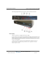
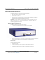
About the Wave IP 500 Server
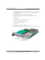
The Wave IP 500 Server consists of the following components. Each is described in the
following sections.
•
Wave Server chassis components. See the next section.
•
Power supply. See page 3-5.
•
Expansion options, including expansion modules and the Media Resource Module
(MRM). See page 3-6.
Important: Note that a monitor, keyboard, and mouse are not included with and are not
supported on the Wave Server. You use the administrator PC, described in Chapter 5, to
configure and manage the Wave ISM.
Maximum phone capacity
The Wave IP 500 Server supports the following:
•
A maximum of 50 analog, digital, and SIP phones in a mixed configuration.
•
A maximum of 50 SIP phones in a SIP-only configuration (with no digital or analog
phones)
•
A maximum of up to 48 digital phones in a digital-only configuration (with no SIP
endpoints or analog phones)
Wave Server Installation Guide
Release 2.0 Service Pack 1
April 2011
3-3
Chapter 3: Setting Up the Wave IP 500 Server
About the Wave IP 500 Server
About the Wave IP 500
The Wave IP 500 Server consists of the following:
•
19-inch rack-mountable chassis that includes room for expansion.
•
VAM (1GHz Celeron, 1GB memory)
•
Power supply
•
Integrated Services Card 2 (ISC2), an embedded processor that provides primary system
control including voice processing and packet switching elements.
•
Dual serial ATA (SATA) hard disk drives
About the ISC2
The ISC2 includes the following:
•
Embedded Intel IXP processor
•
Fault Monitor Module
•
Digital Signal Processor (DSP)
•
Media Resource Module (MRM) connector for an optional MRMA module for expanded
DSP functionality
Wave Server Installation Guide
Release 2.0 Service Pack 1
April 2011
3-4
Chapter 3: Setting Up the Wave IP 500 Server
About the Wave IP 500 Server
•
2 analog station ports (RJ-11 connectors)
•
2 analog trunk ports, loop-start only (RJ-11 connectors)
•
1 external Ethernet switched port, 10/100 base-T.
•
2 USB host ports for communication to the VAM (type A connectors)
•
1 USB device port for service console connection to the embedded processor (type
mini-B connector)
•
1 audio input port for an external music-on-hold source
•
1 audio output port for an external paging system
•
4 system status LEDs and 2 module status LEDs, described in detail in Appendix C
•
Power on/off button
•
Reset button
•
Internal 56K soft modem
•
1 station to trunk power fail connection relay
•
1 alarm relay
Wave Server Installation Guide
Release 2.0 Service Pack 1
April 2011
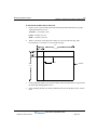
About the Wave IP 500 Server
3-5
Chapter 3: Setting Up the Wave IP 500 Server
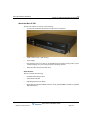
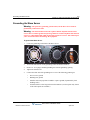
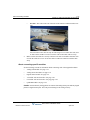
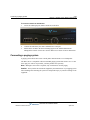
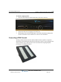
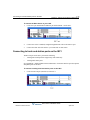
The following diagram illustrates the system ports, LEDs, and buttons on the ISC2:
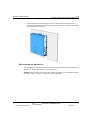
Power supply
The Wave IP 500 Server is equipped with one power supply.
If a power failure occurs, an optional Uninterruptable Power Supply (UPS) can provide several
minutes of system power, allowing a technician to properly shut down the Wave Server. Wave
can also integrate with 3rd-party UPS software to provide graceful shutdown of the system via
network or USB signalling.
A UPS is not provided by Vertical, but can be purchased from a third-party source. For
information about recommended UPS specifications, refer to Appendix C in the Wave
Hardware Reference Guide.
Wave Server Installation Guide
Release 2.0 Service Pack 1
April 2011
3-6
Chapter 3: Setting Up the Wave IP 500 Server
About the Wave IP 500 Server
External power supply for digital phones
An external power supply is required on the Wave IP 500 Server to power digital phones,
because the Wave IP 500 does not provide power to digital phones directly.
The 180W 36V external power supply supports up to 48 Comdial or LGN digital phones (all
currently-supported models.)
Important: Note the following:
•
You must use the external power supply supplied by Vertical—do not substitute a power
supply obtained elsewhere.
•
The external power supply should only be connected and disconnected from the Wave
Server when the Server is powered off. Also, be sure to connect the AC cord before
powering the Wave Server on.
For more information about the external power supply for the Wave IP 500, see the Wave
Hardware Reference Guide.
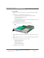
About the dual SATA hard drives
The Wave IP 500 Server chassis has been designed to support redundant hard drives. Dual
SATA hard drives are stacked in the mounting bracket.
•
Disk 0 is physically mounted on top of Disk 1 in the bracket.
•
The disks are labeled as follows:
•
Disk 0 SATA cable is labeled “HD0-TOP”.
•
Disk 1 SATA cable is labeled “HD1-BOTTOM”.
Wave IP 500 expansion options
The ISC2 is the minimum requirement for a Wave IP 500 system.
There are several ways to expand the Wave Server to handle additional users and increased
traffic, and support a wide variety of trunk and station configurations:
•
Expansion modules
•
Media Resource Module (MRM)
For technical specifications for these expansion components, see the Wave Hardware Reference
Guide.
Wave Server Installation Guide
Release 2.0 Service Pack 1
April 2011
3-7
Chapter 3: Setting Up the Wave IP 500 Server
About the Wave IP 500 Server
Expansion modules
Up to 3 modules can be installed in the Wave IP 500 chassis.
The following modules are available:
•
Analog trunk module. Supports 8 analog FXO loop start or ground start trunk ports. See
page 3-18.
•
Analog universal module. Supports 8 analog FXS station ports and 8 analog FXO loop
start or ground start trunk ports. See page 3-18.
•
Digital station module. Depending on the specific model, supports 12 or 24 digital station
ports. See page 3-19.
•
T1 module with serial interface. Supports a single T1 ISDN PRI digital trunk. It features
an integrated CSU/DSU, and allows shared data and voice services over a single T1
circuit. See page 3-20.
•
T1 module (without serial interface). Supports a single T1 ISDN PRI digital trunk. See
page 3-21.
•
E1 EuroISDN module with serial interface. Supports a single E1 ISDN digital trunk. It
features an integrated CSU/DSU, and allows shared data and voice services over a single
E1 circuit. See page 3-22.
•
Quad BRI module. Supports 4 ISDN Basic Rate Interface (BRI) digital trunks and up to 8
simultaneous voice calls, and provides connectivity between the Wave Server and Central
Office (CO) equipment supporting Euro-ISDN BRI communication protocols. See page
3-23.
For installation instructions, see page 3-13.
Media Resource Module (MRM)
Each Wave ISM system is pre-configured to support a specific number of users and concurrent
voice applications. To expand the system’s core telephony, voice processing, and VoIP
capabilities you can add a Media Resource Module. The MRM is a mezzanine-style daughter
board that is installed on the Integrated Services Card (ISC2).
You can install one MRM on the Wave IP 500. The MRM model (MRMA) supported on the
Wave IP 500 provides up to 128 additional voice processing channels.
Note: An MRM is required if you plan to use Quality of Service (QoS) settings with IP
resources for VoIP calls. Contact your Wave provider for more information.
For installation instructions, see page 3-13.
Wave Server Installation Guide
Release 2.0 Service Pack 1
April 2011
3-8
Chapter 3: Setting Up the Wave IP 500 Server
Mounting the Wave Server
Mounting the Wave Server
The Wave Server can be rack mounted or table mounted. See “Environmental requirements” on
page 2-4 for specific requirements on how to prepare site the where the Wave Server will reside.
Caution: Due to the weight of the Wave Server, mount it with assistance whenever possible.
Review “Proper lifting” on page 2-7 before rack mounting.
Important: Note the following:
•
Do not place anything on or against the chassis that prevents proper ventilation. Be sure
to allow a minimum cooling clearance of 4 inches on all sides of the Wave Server.
•
To prevent the fans from pulling dust into the chassis, mount the Wave Server at least 2
feet (0.5 meters) above the floor. Do not operate the Wave Server at floor level.
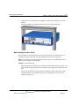
Rack mounting the Wave Server
The Wave Server is shipped ready to be rack mounted. The Wave Server requires an EIA- or
IEC-compliant, 19-inch rack for proper mounting. See “Physical specifications” on page 2-4 for
the dimensions of the Wave Server, including rack height.
To rack mount the Wave Server:
1.
Insert a rack mounting screw loosely into each side of the rack.
2.
Slide the Wave Server into the rack and hang it onto the screws using either the keyhole
or slot on each mounting bracket. (This frees you from having to hold the chassis in place
as you continue.)
3.
Tighten the screws, and then insert and tighten a second rack mounting screw in each
bracket.
Table mounting the Wave Server
Table mounting is a convenient solution for temporary or mobile operation requirements of the
Wave Server. Do not place the Wave Server on the floor.
Caution: Ensure that the table supports the weight of your Wave Server. See “Proper lifting”
on page 2-7 for system weight specifications.
Wave Server Installation Guide
Release 2.0 Service Pack 1
April 2011
3-9
Chapter 3: Setting Up the Wave IP 500 Server
Grounding the Wave Server
Grounding the Wave Server
Warning: The protective ground lug (earth contact) on the Wave Server must be
permanently connected to earth.
Warning: The National Electrical Code requires that the telephone and electrical
services have a common ground. If separate grounds are used for telephone and electrical
services, a voltage differential could develop between the two services. This could expose
you to an electrical shock and damage the equipment.
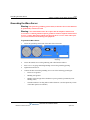
To ground the Wave Server:
1.
Locate the ground lug on the back of the Wave Server.
2.
Loosen the slotted screw on the ground lug with a flat-head screwdriver.
3.
Insert a 10- or 12-gauge stranded grounding wire into the ground lug opening.
4.
Tighten the slotted screw.
5.
Connect the other end of the grounding wire to one of the following ground types:
•
Power service ground
•
Building steel ground
•
Metallic cold water pipe that is bonded to a power ground (if permitted by local
building codes)
•
Ground rod that is 5 feet long and 5/8 inch in diameter. (Use this option only if none
of the other options are available.)
Wave Server Installation Guide
Release 2.0 Service Pack 1
April 2011
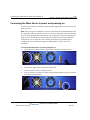
Connecting the Wave Server to power and powering on
3-10
Chapter 3: Setting Up the Wave IP 500 Server
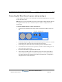
Connecting the Wave Server to power and powering on
Connect the Wave Server to a dedicated circuit using the supplied power cord. Do not use any
other power cord.
Note: There are 2 power cord models, one for use in the US and one for International (EU) use.
See Appendix D in the Wave Hardware Reference Guide for voltage and current specifications.
If you are using digital phones on the Wave IP 500, you must also connect the external power
supply used to power the phones. The external power supply does not require a dedicated
circuit. Be sure you are using the correct external power supply for your digital phone
configuration. See “External power supply for digital phones” on page 3-6 for more
information.
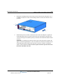
To connect the Wave Server to power and power on:
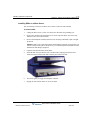
1.
Locate the power outlet and power toggle switch on the back of the Wave Server.
2.
Set the power supply rocker switch to the off position.
3.
Connect the power cable to a dedicated circuit.
4.
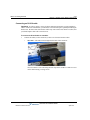
If you are using an external power supply to support digital phones, locate the connector
to the right of the ground lug.
Wave Server Installation Guide
Release 2.0 Service Pack 1
April 2011
3-11
Chapter 3: Setting Up the Wave IP 500 Server
Connecting the Wave Server to your LAN
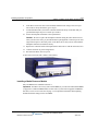
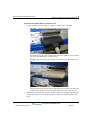
5.
Connect the external power supply cable to the connector, and then connect the cable to
power.
6.
Power on the Wave Server by toggling the rocker switch, and then press the red button on
the front of the Wave Server.
7.
Observe the status LEDs on the front of the Wave Server chassis to ensure that the system
initialization completes successfully and that there are no component failures.
For complete details of the information provided by the status LEDs, see Appendix C,
“Integrated Services Card Status LEDs.”
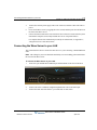
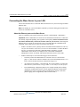
Connecting the Wave Server to your LAN
This section describes how to connect the Wave Server to your LAN using a standard Ethernet
cable.
Note: The cabling for your LAN should be installed by a network cabling professional before
the arrival of the Wave Server.
To connect the Wave Server to your LAN:
1.
Locate the 8-pin modular RJ-45 Ethernet port labeled ENET on the front of the ISC2.
2.
Connect one end of a standard, straight-through Ethernet cable to the ENET port.
3.
Connect the other end of the cable to your LAN’s hub or data switch.
Wave Server Installation Guide
Release 2.0 Service Pack 1
April 2011
3-12
Chapter 3: Setting Up the Wave IP 500 Server
Connecting to trunk and station ports on the ISC2
Connecting to trunk and station ports on the ISC2
The RJ-11 ports on the ISC2 provide the following:
•
2 analog FXO trunk ports that support loop start trunks only.
•
2 analog FXS station ports.
See Appendix B, ”Trunk and Station Ports and Pinouts” for RJ-11 interface port descriptions
and pinout pairs for the ISC2.
To connect to analog trunk and station ports on the ISC2:
1.
Locate the RJ-11 ports (labeled Trunk 1-2 and SLT 1-2) on the ISC2.
2.
Using standard phone cables, connect station and trunk ports directly to phone or wall
jacks or a patch panel.
Power failover support
Wave provides failover telephone service (power failure lifeline) in the event of a power failure.
If the power fails, the analog phone connected to the SLT 1 port on the ISC2 automatically
connects to the analog trunk plugged into the Trunk 1 port, enabling that analog phone to make
calls even if the Wave Server is not functioning.
When using that analog phone during a power failure, you do not need to dial an outside access
digit (for example 9) to place an outside call.
Hint: When setting up your telephones, locate the analog telephone connected to the SLT 1 port
in a convenient area, such as the lobby or front desk, so that it is easily accessible during a power
failure.
Wave Server Installation Guide
Release 2.0 Service Pack 1
April 2011
3-13
Chapter 3: Setting Up the Wave IP 500 Server
Installing expansion components
Installing expansion components
This section describes how to install the following components to expand the Wave IP 500:
•
Media Resource Module (MRM). See the next section.
•
Expansion modules. See page 3-13.
For technical specifications for these expansion components, see the Wave Hardware Reference
Guide.
Installing a Media Resource Module
Only one MRM (an MRMA) can be installed on the ISC2.
Important: Your Wave Server may come with an MRM, or you can order and install an MRM
at a later time. If you do add an MRM at a later time, be sure to review the note on page 7-5 for
important information about updating default IP network settings for the new MRM.
To install an MRM:
1.
Unplug the Wave Server’s power cord, but do not disconnect the grounding wire.
2.
Remove the top cover.
3.
Align the MRM over the standoffs, and then fasten the 4 retention screws in the corner
holes.
4.
Plug the MRM ribbon connector into connector P2 (the light-blue 40-pin socket) on the
ISC2.
5.
Replace the top cover and reattach it with the original screws.
6.
Reconnect the Wave Server to power.
Installing expansion modules
This section provides guidelines for installing all modules. See “About connecting modules” on
page 3-15 for information on connecting trunks, stations, and other devices to specific modules
after you have installed them.
Caution: The Wave Server’s analog station interface is not designed to withstand surges
commonly associated with wires that are exposed to the external environment. Do not route the
wires connecting analog station modules to stations outside the building where the Wave Server
is located.
Note: Because the required steps are different, installing a Media Resource Module is covered
separately on page 3-13.
Wave Server Installation Guide
Release 2.0 Service Pack 1
April 2011
3-14
Chapter 3: Setting Up the Wave IP 500 Server
Installing expansion components
To install modules:
1.
Unplug the Wave Server’s power cord, but do not disconnect the grounding wire.
2.
Remove the plastic bezel that covers the front of the Wave IP 500. To do so, grasp the
tabs of the bezel on both sides and pull forward.
3.
Remove the blank module faceplate.
4.
Insert modules and cards carefully.
5.
Seat the module properly for good electrical connection. Engage the module by pressing
gently on it—be sure to press on the faceplate, not a connector or component on the
module.
6.
Install blank faceplates on all unused slots.
7.
Reconnect the Wave Server to power.
Module status LEDs
Each module has a pair of LEDs that indicate the component’s status:
Status
Red LED
Green LED
System is in an early boot phase.
off
off
System boot is in progress, or a firmware flash
update is in progress.
Blinking red
off
System is operational with no errors.
off
Blinking green
System shutdown is in progress.
Blinking red
Blinking green
Error condition exists on the system.
Red
off
System upgrade is in progress.
Blinking red
Green
Hard drive imaging in progress (via the Wave
System Recovery Disk.)
Red
Green
T1/E1 module alarm indicators
The T1 module with serial interface and E1 EuroISDN module with serial interface have
additional alarm indicators, one set for the T1/E1 port and one set for the serial port, located to
the left of the module status LEDs. See “Alarm indicators” in Chapter 15 in the Wave Hardware
Reference Guide for more information.
Wave Server Installation Guide
Release 2.0 Service Pack 1
April 2011
3-15
Chapter 3: Setting Up the Wave IP 500 Server
About connecting modules
About connecting modules
This section provides general information about connecting trunks, stations, and other devices
to modules. Instructions for connecting specific modules are described in subsequent sections.
Important: Before connecting modules, ensure that the following tasks have been completed,
depending on your configuration:
•
The punchdown block or patch panel has been properly wired.
•
Analog and T1 trunks have been installed by your service provider.
•
Incoming analog DID trunks have been tested to ensure no voltage is present, as well as
to verify that they are DID trunks.
About cable connections
Modules and cards use standard cable connectors and jacks, as listed in the following table:
Module
RJ-11
Integrated Services
Card (ISC2)
4
RJ-21X
RJ-45
RJ-48C
1
Analog trunk module
1
Analog universal
module
1
Digital station module
1
T1 module with serial
interface
1
T1 module (without
serial interface)
1
E1 EuroISDN module
with serial interface
1
Quad BRI module
3.5 mm
audio
USB
2
3
4
Note: Some modular connectors look alike. Verify that your cables use the standard connectors
specified for a particular module.
Wave Server Installation Guide
Release 2.0 Service Pack 1
April 2011
3-16
Chapter 3: Setting Up the Wave IP 500 Server
About connecting modules
Connecting an RJ-21X cable
Important: In order to ensure a secure fit when connecting an RJ-21X (25-pair amphenol)
cable to a station or trunk module, you should use 3/4-inch 4-40 captive (partially threaded) pan
head screws. Be aware that some RJ-21X cables may come with screws that are too short, and
you should replace them with 3/4-inch screws.
To connect an RJ-21X cable to a module:
1.
Connect the cable(s) to the connector(s). There are 2 kinds of RJ-21X cables:
•
180° cable—The cable comes straight out the back of the connector.
You can connect a 180° cable using the bale clips on the module to connect to a slot
on the cable housing, or using screws.
Wave Server Installation Guide
Release 2.0 Service Pack 1
April 2011
3-17
Chapter 3: Setting Up the Wave IP 500 Server
About connecting modules
•
90° cable—The cable comes out of the side of the connector and then makes a 90°
turn.
You can connect a 90° cable on only one side using a screw. On the other side, use a
tie down on the module or card to secure the cable to the board with a tie wrap.
2.
Make sure that the cables are securely connected. The tabs on modular connectors click
in when the cables are secure. Secure the cable to an RJ-21X connector with the cable
strap.
About connecting specific modules
See the following sections for information about connecting each of the supported modules:
•
Analog trunk module. See page 3-18.
•
Analog universal module. See page 3-18.
•
Digital station module. See page 3-19.
•
T1 module with serial interface. See page 3-20.
•
E1 module with serial interface. See page page 3-22.
•
Quad BRI module. See page 3-23.
Caution: Ensure that only analog phones are connected to analog station ports and only digital
phones to digital station ports. This will prevent damage to the analog circuitry.
Wave Server Installation Guide
Release 2.0 Service Pack 1
April 2011
3-18
Chapter 3: Setting Up the Wave IP 500 Server
Connecting the analog trunk module
Connecting the analog trunk module
The analog trunk module provides 8 analog FXO loop start or ground start trunk ports. It is a
partial-width module that can be installed in any module slot.
See Appendix B, ”Trunk and Station Ports and Pinouts” for RJ-21X interface port descriptions
and pinout pairs for the analog trunk module.
To connect the analog trunk module:
1.
Locate the RJ-21X port on the module.
2.
Connect the RJ-21X (25-pair amphenol) cable to the port. (See “Connecting an RJ-21X
cable” on page 3-16.)
3.
The cable can then be punched down, most commonly to a patch panel port, but it can
also be punched down to a punchdown block where it is then cross-connected to the
station cabling or analog circuits.
Connecting the analog universal module
The analog universal module provides the following:
•
8 analog FXO trunk ports, supporting loop start, ground start, and analog DID trunks
(analog DID trunks support inbound calling only).
•
8 analog FXS station ports.
The analog universal module is a partial-width module that can be installed in any module slot.
See Appendix B, ”Trunk and Station Ports and Pinouts” for RJ-21X interface port descriptions
and pinout pairs for the analog universal module.
To connect the analog universal module:
1.
Locate the RJ-21X port on the module.
2.
Connect the RJ-21X (25-pair amphenol) cable to the port. (See “Connecting an RJ-21X
cable” on page 3-16.)
3.
The cable can then be punched down, most commonly to a patch panel port, but it can
also be punched down to a punchdown block where it is then cross-connected to the
station cabling or analog circuits.
Wave Server Installation Guide
Release 2.0 Service Pack 1
April 2011
3-19
Chapter 3: Setting Up the Wave IP 500 Server
Connecting the digital station module
Connecting the digital station module
Depending on the specific model, the digital station module provides 12 or 24 digital station
ports (see the Wave Hardware Reference Guide for details.) It is a partial-width module that can
be installed in any module slot.
See Appendix B for RJ-21X interface port descriptions and pinout pairs for the digital station
module.
To connect the digital station module:
1.
Locate the RJ-21X port on the module.
2.
Connect the RJ-21X cable from your punchdown block or patch panel to the port. (See
“Connecting an RJ-21X cable” on page 3-16.)
Connecting the external power supply for digital phones
You must use an external power supply to provide power to digital phones. See “External power
supply for digital phones” on page 3-6 for details.
To connect the external power supply:
1.
Locate the power outlet on the back of the Wave IP 500.
2.
Connect the power cord on the external power supply to the outlet.
Wave Server Installation Guide
Release 2.0 Service Pack 1
April 2011
3-20
Chapter 3: Setting Up the Wave IP 500 Server
Connecting the T1 module with serial interface
Connecting the T1 module with serial interface
Note: This section describes how to connect the T1 module with serial interface. For
information about installing the 1-port T1 module, see page 3-21.
The T1 module with serial interface and built-in CSU/DSU supports one T1 or ISDN PRI digital
trunk to provide shared data and voice services over a single T1 circuit.
There are 3 connectors on the T1 module:
•
The RJ-48C port is used to connect to the T1 or ISDN PRI network interface.
•
The DB-60 port provides V.35 serial communications for data connections, for example
to connect to the DB-60 cable from an external router.
•
The bantam jack located to the right of the RJ-48C port accepts a 3-conductor Bantam
cable. It is provided for diagnostic purposes and is to be used only by an authorized
technician.
The T1 module is a partial-width module that can be installed in any module slot.
See the note on page 3-14 for information about alarm indicators specific to this module.
To connect the T1 module with serial interface:
1.
Locate the RJ-48C port and DB-60 connector on the module.
2.
Connect the T1 cable to the RJ-48C port.
3.
Connect the serial cable from your external router to the DB-60 port.
The serial cable may be either a DB-60 male to DB-60 male cable, or a DB-60 male to
V.35 female DCE cable. In either case the DB-60 male connector goes to the DB-60
female port on the ISC2.
Caution: Use care when connecting or disconnecting the serial cable. Because of the
connector’s small size and high pin count, pins on the cable connector can be easily bent
and the DB-60 port may be damaged.
Wave Server Installation Guide
Release 2.0 Service Pack 1
April 2011
Connecting the T1 module (without serial interface)
3-21
Chapter 3: Setting Up the Wave IP 500 Server
Connecting the T1 module (without serial interface)
Note: This section describes how to connect the 1-port T1/PRI module without serial interface.
For information about installing the 1-port T1 module with serial interface, see page 3-20.
The T1 module supports one T1 or ISDN PRI digital trunk.
There are 2 connectors on the T1 module:
•
The RJ-48C port is used to connect to the T1 or ISDN PRI network interface.
•
The bantam jack located to the right of the RJ-48C port accepts a 3-conductor Bantam
cable. It is provided for diagnostic purposes and is to be used only by an authorized
technician.
The T1 module is a partial-width module that can be installed in any module slot. This module
has one alarm indicator for the T1 port. See “Alarm indicators” in Chapter 15 in the Wave
Hardware Reference Guide for more information.
To connect the T1 module:
1.
Locate the RJ-48C port on the module.
2.
Connect the T1 cable to the RJ-48C port.
Wave Server Installation Guide
Release 2.0 Service Pack 1
April 2011
Connecting the E1 EuroISDN module with serial interface
3-22
Chapter 3: Setting Up the Wave IP 500 Server
Connecting the E1 EuroISDN module with serial interface
The E1 EuroISDN module with serial interface and built-in CSU/DSU supports one E1 ISDN
digital trunk to provide shared data and voice services over a single E1 circuit.
There are 3 connectors on the E1 EuroISDN module:
•
The RJ-48C port is used to connect to the E1 ISDN network interface.
•
The DB-60 port provides V.35 serial communications for data connections, for example
to connect to the DB-60 cable from an external router.
•
The bantam jack located to the right of the RJ-48C port accepts a 3-conductor Bantam
cable. It is provided for diagnostic purposes and is to be used only by an authorized
technician.
The E1 EuroISDN module is a partial-width module that can be installed in any module slot.
See the note on page 3-14 for information about alarm indicators specific to this module.
To connect the E1 EuroISDN module:
1.
Locate the RJ-48C port and DB-60 connector on the module.
2.
Connect the E1 cable to the RJ-48C port.
3.
Connect the serial cable from your external router to the DB-60 port.
The serial cable may be either a DB-60 male to DB-60 male cable, or a DB-60 male to
V.35 female DCE cable. In either case the DB-60 male connector goes to the DB-60
female port on the ISC1ISC2.
Caution: Use care when connecting or disconnecting the serial cable. Because of the
connector’s small size and high pin count, pins on the cable connector can be easily bent
and the DB-60 port may be damaged.
Wave Server Installation Guide
Release 2.0 Service Pack 1
April 2011
3-23
Chapter 3: Setting Up the Wave IP 500 Server
Connecting the Quad BRI module
Connecting the Quad BRI module
The Quad BRI Module supports ISDN Basic Rate Interface (BRI) digital trunks, and provides
connectivity between the Wave Server and Central Office (CO) equipment supporting
Euro-ISDN BRI communication protocols. The Quad BRI Module supports 4 Euro-ISDN BRI
trunks and up to 8 simultaneous voice calls.
There are 4 RJ-45 connectors on the Quad BRI module.
The Quad BRI module is a partial-width module that can be installed in any module slot or in
any universal slot via a module converter.
To connect the Quad BRI module:
1.
Locate the RJ-45 ports on the module.
2.
Connect each port to a Euro-ISDN BRI trunk cable.
Connecting a music-on-hold (MOH) system
A music-on-hold device plays prerecorded music or messages to callers—either from a tape or
CD—when they are placed on hold or while being transferred.
The Wave Server is compatible with most standard music-on-hold devices that connect via a 3.5
mm stereo plug. If a cable is not provided, you must purchase one separately.
Note: Although a stereo cable is required, music on hold only plays in mono.
Caution: Always follow the instructions supplied by the manufacturer of your music-on-hold
device when installing and connecting the device to avoid possible injury to yourself or damage
to the equipment.
Wave Server Installation Guide
Release 2.0 Service Pack 1
April 2011
3-24
Chapter 3: Setting Up the Wave IP 500 Server
Connecting a paging system
To connect a music-on-hold device:
1.
Locate the audio input port (labeled Audio In) on the ISC2.
2.
Connect the cable from your music-on-hold device to the port.
3.
Enable music on hold in the General Settings applet of the Global Administrator
Management Console. See the Wave Global Administrator Guide for more information.
Connecting a paging system
A paging system allows Wave users to make public announcements over a loudspeaker.
The Wave Server is compatible with most standard paging systems that connect via a 3.5 mm
stereo plug. If a cable is not provided, you must purchase one separately.
Note: Although a stereo cable is required, only one channel is used for paging.
Caution: Always follow the instructions supplied by the manufacturer of your paging system
when installing and connecting the system to avoid possible injury to yourself or damage to the
equipment.
Wave Server Installation Guide
Release 2.0 Service Pack 1
April 2011
3-25
Chapter 3: Setting Up the Wave IP 500 Server
Connecting a DSS Console
To connect a paging system:
1.
Locate the audio output port (labeled Audio Out) on the front of the ISC2.
2.
Connect the cable from your paging system to the port.
3.
Enable paging in the General Settings applet of the Global Administrator Management
Console. See the Wave Global Administrator Guide for more information.
Connecting a DSS Console
The Edge 700 Direct Station Selection (DSS) 48-Button Console expands a receptionist’s
digital phone with 48 additional flexible buttons with LEDs to connect to system endpoints such
as user extensions. Up to 5 DSS Consoles can be associated with a single digital phone,
providing up to 240 additional buttons.
Wave Server Installation Guide
Release 2.0 Service Pack 1
April 2011
Connecting a DSS Console
3-26
Chapter 3: Setting Up the Wave IP 500 Server
The DSS Console connects to a digital station port on any of the following modules on the Wave
IP 500:
•
12-Port Digital Station Module (VW5-12DS2-M)
•
24-Port Digital Station Module (VWU-24DS2-M)
For instructions on how to configure a DSS Console for a user, see “The Phone \ DSS Consoles
tab” in Chapter 10 in the Wave Global Administrator Guide.
To connect a DSS Console:
1.
Locate an unused port on the digital station module.
2.
Connect the DSS Console to the digital station port using an RJ-11 cable. The maximum
cable length between the Wave Server and the DSS Console is 1968 feet (600 m).
Note: There is no physical connection between the DSS Console and the user’s digital
phone.
Wave Server Installation Guide
Release 2.0 Service Pack 1
April 2011
Chapter 4
Setting Up the Wave IP 2500 Server
CHAPTER CONTENTS
About the Wave IP 2500 Server. . . . . . . . . . . . . . . . . . . . . . . . . . . . . . . . . . . . . 4-2
Mounting the Wave Server. . . . . . . . . . . . . . . . . . . . . . . . . . . . . . . . . . . . . . . . . 4-7
Grounding the Wave Server. . . . . . . . . . . . . . . . . . . . . . . . . . . . . . . . . . . . . . . 4-12
Connecting the Wave Server to power and powering on . . . . . . . . . . . . . . . . . 4-13
Connecting the Wave Server to your LAN . . . . . . . . . . . . . . . . . . . . . . . . . . . . 4-14
Connecting to trunk and station ports on the ISC1. . . . . . . . . . . . . . . . . . . . . . 4-15
Installing expansion components . . . . . . . . . . . . . . . . . . . . . . . . . . . . . . . . . . . 4-16
About connecting modules and cards . . . . . . . . . . . . . . . . . . . . . . . . . . . . . . . 4-21
Connecting the analog trunk module . . . . . . . . . . . . . . . . . . . . . . . . . . . . . . . . 4-24
Connecting the analog universal module . . . . . . . . . . . . . . . . . . . . . . . . . . . . . 4-25
Connecting the digital station module . . . . . . . . . . . . . . . . . . . . . . . . . . . . . . . 4-25
Connecting the T1 module with serial interface . . . . . . . . . . . . . . . . . . . . . . . . 4-26
Connecting the T1 module (without serial interface) . . . . . . . . . . . . . . . . . . . . 4-27
Connecting the E1 EuroISDN module with serial interface . . . . . . . . . . . . . . . 4-27
Connecting the Quad BRI module . . . . . . . . . . . . . . . . . . . . . . . . . . . . . . . . . . 4-28
Connecting the digital station card . . . . . . . . . . . . . . . . . . . . . . . . . . . . . . . . . . 4-29
Connecting a music-on-hold (MOH) system . . . . . . . . . . . . . . . . . . . . . . . . . . 4-30
Connecting a paging system . . . . . . . . . . . . . . . . . . . . . . . . . . . . . . . . . . . . . . 4-31
Connecting a DSS Console . . . . . . . . . . . . . . . . . . . . . . . . . . . . . . . . . . . . . . . 4-32
Important: This chapter applies to you if you are installing a Wave IP 2500 Server. If you are
installing a Wave IP 500 Server, go to Chapter 3.
Wave Server Installation Guide
Release 2.0 Service Pack 1
April 2011
4-2
Chapter 4: Setting Up the Wave IP 2500 Server
About the Wave IP 2500 Server
About the Wave IP 2500 Server
The Wave IP 2500 Server consists of the following components.
•
Wave Server base unit. See the next section.
•
Power supply. See page 4-4.
•
Expansion options, including expansion cards and modules, Expansion Units (EXUs),
and the Media Resource Modules (MRMs). See page 4-5.
Important: Note that a monitor, keyboard, and mouse are not included with and are not
supported on the Wave Server. You use the administrator PC, described in Chapter 5, to
configure and manage the Wave ISM.
About the Wave IP 2500 base unit
The Wave IP 2500 base unit consists of the following:
•
A 19-inch rack-mountable chassis that includes room for expansion.
•
The Wave Integrated Services Card (ISC1), an embedded processor that provides primary
system control including voice processing and packet switching elements.
About the ISC1
The ISC1 includes the following:
•
6 SIP Gateway ports
•
4 analog FXO trunk ports (first four pairs on a shared RJ-21X connector)
•
4 analog FXS station ports (last four pairs on a shared RJ-21X connector)
Wave Server Installation Guide
Release 2.0 Service Pack 1
April 2011
4-3
Chapter 4: Setting Up the Wave IP 2500 Server
About the Wave IP 2500 Server
•
2 10/100 Mbps Ethernet ports (ports are mirrored and are not separately addressable). See
“About the Ethernet ports on the Wave Server” on page 4-14 for important information
about using these ports.
•
2 partial-width slots that can accommodate 2 expansion modules
•
2 full-width universal slots that can accommodate 2 expansion cards or modules
•
1 USB device port
•
1 USB host port
•
RJ-21X connector (with embedded FXS and FXO ports)
•
Audio port for an external music-on-hold source
•
1 port for an external paging system
•
V.34 Fax modem
•
Status LEDs (described in detail in Appendix C)
The following diagram illustrates the system ports, LEDs, and buttons on the front of the ISC1:2
Wave Server Installation Guide
Release 2.0 Service Pack 1
April 2011
About the Wave IP 2500 Server
4-4
Chapter 4: Setting Up the Wave IP 2500 Server
Power supply
The Wave IP 2500 Server is equipped with one power supply.
If a power failure occurs, an optional Uninterruptable Power Supply (UPS) can provide several
minutes of system power, allowing a technician to properly shut down the Wave Server. Wave
can also integrate with 3rd-party UPS software to provide graceful shutdown of the system via
network or USB signalling.
A UPS is not provided by Vertical, but can be purchased from a third-party source. For
information about recommended UPS specifications, refer to Appendix C in the Wave Server
Hardware Reference Guide.
Minimum configuration
The ISC1 is the minimum requirement for a Wave IP 2500 system. Expansion modules and
cards are available to expand the Wave IP 2500 Server base unit to support a wide variety of
trunk and station configurations.
Redundancy
The Wave IP 2500 Server chassis has been designed to support redundant hard drives. All Wave
IP 2500 Servers ship with redundant hard drives as part of the standard configuration.
In case of a primary (master) hard drive failure, you can use the redundant (slave) hard drive to
run the Wave IP 2500 Server chassis.
Fault monitoring
A proprietary Fault Monitor Module is an integral part of the embedded firmware running on
the ISC1, and receives system error-trace messages and stores them in memory. As soon as the
Wave Server is powered on, the Fault Monitor Module starts monitoring the status of the
Microsoft Windows Server operating system, the power supply status, the ISC1temperature,
and the Power-on/Shutdown button. You can configure the Fault Monitor Module to dial a pager
number that notifies the system administrator of system errors.
For more information, see Appendix A, “Fault Monitor Module and Trace Log” in the Wave
Server Hardware Reference Guide.
To configure the Fault Monitor Module, see the Wave Global Administrator Guide.
Wave Server Installation Guide
Release 2.0 Service Pack 1
April 2011
4-5
Chapter 4: Setting Up the Wave IP 2500 Server
About the Wave IP 2500 Server
Wave IP 2500 expansion options
The ISC1 is the minimum requirement for a Wave IP 2500 system.
There are several ways to expand the Wave Server base unit to handle additional users and
increased traffic, and support a wide variety of trunk and station configurations:
•
Expansion cards and modules
•
Expansion Units (EXUs)
•
Media Resource Modules (MRMs)
For technical specifications for these expansion components, see the Wave Server Hardware
Reference Guide.
Expansion cards and modules
The Wave Server supports two kinds of expansion boards—modules and cards.
•
Modules are partial-width boards that can be installed in module slots in the base unit or
in Expansion Units (EXUs, described on page 4-6).
Modules can also be installed in universal card slots in the base unit or in EXUs using the
IP 2500 Module Conversion Kit (VW-IP2500-CONV), a mechanical assembly which
attaches to a module.
The following modules are available:
•
Analog trunk module. Supports 8 analog FXO loop start or ground start trunk ports.
See page 4-24.
•
Analog universal module. Supports 8 analog FXS station ports and 8 analog FXO
loop start or ground start trunk ports. See page 4-25.
•
Digital station module. Depending on the specific model, supports 12 or 24 digital
station ports. See page 4-25.
•
T1 module with serial interface. Supports a single T1 (PRI or CAS signaling) digital
trunk. It features an integrated CSU/DSU, and allows shared data and voice services
over a single T1 circuit. See page 4-26.
•
T1 module (without serial interface). Supports a single T1 (PRI or CAS signaling)
digital trunk. See page 4-27.
Wave Server Installation Guide
Release 2.0 Service Pack 1
April 2011
4-6
Chapter 4: Setting Up the Wave IP 2500 Server
About the Wave IP 2500 Server
•
•
E1 EuroISDN module with serial interface. Supports a single E1 ISDN digital trunk.
It features an integrated CSU/DSU, and allows shared data and voice services over
a single E1 circuit. See page 4-27.
•
Quad BRI module. Supports 4 Basic Rate Interface (BRI) digital trunks and up to 8
simultaneous voice calls, and provides connectivity between the Wave Server and
Central Office (CO) equipment supporting Euro-ISDN BRI communication
protocols. See page 4-28.
Cards are full-width boards that support more ports than modules do. Cards can be
installed in the universal card slots in the base unit or in EXUs.
The following cards are available:
•
Analog station card. Supports 24 analog FXS station ports. See page 4-29.
•
Digital station card. Depending on the model, supports 12 or 24 digital station ports.
See page 4-29.
For installation instructions, see page 4-20.
Expansion Units (EXUs)
An EXU provides 2 universal slots that can each support one module or card. Up to 4 modular
EXUs can be mounted on top of the Wave IP 2500 Server base unit. A fully expanded Wave IP
2500 Server with 4 EXUs provides 8 additional universal slots.
For installation instructions, see page 4-17.
Media Resource Modules (MRMs)
Each Wave ISM system is pre-configured to support a specific number of users and concurrent
voice applications. To expand the system’s core telephony, voice processing, and VoIP
capabilities you can add a Media Resource Module. The MRM is a mezzanine-style daughter
board that is installed on the Integrated Services Card (ISC1).
You can install one MRM on the Wave IP 2500 Server.There are 3 available MRM models
(MRMA, MRMB, and MRMC) that provide up to 128, 256, or 384 additional voice processing
channels.
Note: At least one MRM is required if you plan to use Quality of Service (QoS) settings with
IP resources for VoIP calls. Contact your Wave provider for more information.
For installation instructions, see page 4-18.
Wave Server Installation Guide
Release 2.0 Service Pack 1
April 2011
4-7
Chapter 4: Setting Up the Wave IP 2500 Server
Mounting the Wave Server
Mounting the Wave Server
The Wave IP 2500 Server can be rack mounted, wall mounted, or table mounted. See
“Environmental requirements” on page 2-4 for specific requirements on how to prepare site the
where the Wave Server will reside.
Caution: Due to the weight of the Wave Server, mount it with assistance whenever possible.
Review “Proper lifting” on page 2-7 before rack mounting.
Important: Note the following:
•
Do not place anything on or against the base unit that prevents proper ventilation. Be sure
to allow a minimum cooling clearance of 4 inches on all sides of the Wave Server.
•
To prevent the fans from pulling dust into the base unit, mount the Wave Server at least 2
feet (0.5 meters) above the floor. Do not operate the Wave Server at floor level.
Rack mounting the Wave Server
The Wave IP 2500 Server is shipped ready to be rack mounted. The Wave Server requires an
EIA- or IEC-compliant, 19-inch rack for proper mounting. See “Physical specifications” on
page 2-4 for the dimensions of the Wave Server, including rack height.
To rack mount the Wave Server:
1.
Insert a rack mounting screw loosely into each side of the rack.
2.
Slide the Wave Server base unit into the rack and hang it onto the screws using either the
keyhole or slot on each mounting bracket. (This frees you from having to hold the base
unit in place as you continue.)
Wave Server Installation Guide
Release 2.0 Service Pack 1
April 2011
4-8
Chapter 4: Setting Up the Wave IP 2500 Server
Mounting the Wave Server
3.
Tighten the screws, and then insert and tighten a second rack mounting screw in each
bracket.
When successfully rack-mounted, the Wave Server base unit looks like this:
Wall mounting the Wave Server
You can mount the Wave IP 2500 Server base unit onto a wall by first attaching a piece of
prepared plywood to studs in the wall, then attaching the base unit to the plywood.
Note: You can only wall mount the Wave Server base unit itself —wall mounting is not an
option if you are using one or more EXUs.
Caution: Note the following:
•
Do not attach the base unit directly to a wall without using the plywood as a support—the
plywood must be firmly attached to wall studs in order to support the weight of the base
unit.
•
Do not wall mount the base unit so that the cards appear in a horizontal position. Only
wall mount the base unit so that the cards are in a vertical position, as shown in the
illustration on page 4-11.
Wave Server Installation Guide
Release 2.0 Service Pack 1
April 2011
4-9
Chapter 4: Setting Up the Wave IP 2500 Server
Mounting the Wave Server
To wall mount the Wave Server base unit:
1.
Prepare a piece of plywood that meets the following minimum dimensions for proper
ventilation and service access:
Thickness—0.75 inches (2 cm)
Height—24 inches (61 cm)
Width— 34 inches (86.4 cm)
2.
Draw a vertical line on the plywood 4 inches (10.2 cm) from the left edge, and a
horizontal line 3-1/4 inches (8.3 cm) from the top edge:
34 “
4”
(10.2 cm)
(6.4 cm)
3 1/4"
(8.3 cm)
Two lines
Plywood
24"
(61 cm)
3.
Locate supporting studs in your wall, and firmly attach the prepared piece of plywood to
the studs using the appropriate screws.
4.
If the mounting brackets are currently installed on the front of the Wave Server, remove
them.
Wave Server Installation Guide
Release 2.0 Service Pack 1
April 2011
Mounting the Wave Server
4-10
Chapter 4: Setting Up the Wave IP 2500 Server
5.
Position the mounting brackets at the bottom of each of the base unit side panels. Use a
#2 Phillips screwdriver to fasten each mounting bracket to the base unit with the screws
provided.
6.
With another person’s assistance, lift the Wave Server base unit and place it against the
wall-mounted plywood. Line up the left side of the base unit with the vertical line that
you drew on the plywood, and line up the top of the base unit with the horizontal line that
you drew.
Important: According to the directions in this step, the face plate will be facing to the
right (see the following illustration.) You can rotate the base unit before attaching it to the
wall-mounted plywood so that the face plate faces to the left, in order to avoid power
outlets or other obstructions. However, the face plate cannot face up or down once the
base unit is mounted to the wall.
Wave Server Installation Guide
Release 2.0 Service Pack 1
April 2011
4-11
Chapter 4: Setting Up the Wave IP 2500 Server
Mounting the Wave Server
7.
Insert and tighten two self-threading #10 screws through each mounting bracket to
securely attach the base unit to the plywood. When successfully wall-mounted, the Wave
Server base unit looks like this:
Table mounting the Wave Server
Table mounting is a convenient solution for temporary or mobile operation requirements of the
Wave Server. Do not place the Wave Server on the floor.
Caution: Ensure that the table supports the weight of your Wave Server including any EXUs.
See “Proper lifting” on page 2-7 for system weight specifications.
Wave Server Installation Guide
Release 2.0 Service Pack 1
April 2011
4-12
Chapter 4: Setting Up the Wave IP 2500 Server
Grounding the Wave Server
Grounding the Wave Server
Warning: The protective ground lug (earth contact) on the Wave Server base unit must
be permanently connected to earth.
Warning: The National Electrical Code requires that the telephone and electrical
services have a common ground. If separate grounds are used for telephone and electrical
services, a voltage differential could develop between the two services. This could expose
you to an electrical shock and damage the equipment.
To ground the Wave Server:
1.
Locate the ground lug on the back of the Wave Server base unit.
2.
Loosen the slotted screw on the ground lug with a flat-head screwdriver.
3.
Insert a 10- or 12-gauge stranded grounding wire into the ground lug opening.
4.
Tighten the slotted screw.
5.
Connect the other end of the grounding wire to one of the following ground types:
•
Power service ground
•
Building steel ground
•
Metallic cold water pipe that is bonded to a power ground (if permitted by local
building codes)
•
Ground rod that is 5 feet long and 5/8 inch in diameter. (Use this option only if none
of the other options are available.)
Wave Server Installation Guide
Release 2.0 Service Pack 1
April 2011
Connecting the Wave Server to power and powering on
4-13
Chapter 4: Setting Up the Wave IP 2500 Server
Connecting the Wave Server to power and powering on
Connect the Wave IP 2500 Server to a dedicated circuit using the supplied power cord. Do not
use any other power cord.
Note: There are 2 power cord models, one for use in the US and one for International (EU) use.
See Appendix D in the Wave Server Hardware Reference Guide for voltage and current
specifications.
To connect the Wave Server to power and power on:
1.
Locate the power outlet and power toggle switch on the back of the Wave Server base
unit.
2.
Set the base unit power supply rocker switch and any EXU power switch rocker switches
located on the back of the Wave Server base unit to the off position.
3.
Connect the power cables from the base unit and any EXUs to dedicated circuits.
4.
Set each EXU's rocker switch to the On position. (The EXU will not actually power on
until the base unit is powered on.)
5.
Power on the base unit by toggling the rocker switch.
6.
Observe the status LEDs on the front of the Wave Server base unit to ensure that the
system initialization completes successfully and that there are no component failures.
For complete details of the information provided by the status LEDs, see Appendix C,
“Integrated Services Card Status LEDs.”
Wave Server Installation Guide
Release 2.0 Service Pack 1
April 2011
Connecting the Wave Server to your LAN
4-14
Chapter 4: Setting Up the Wave IP 2500 Server
Connecting the Wave Server to your LAN
This section describes how to connect the Wave IP 2500 Server to your LAN using a standard
Ethernet cable.
Note: The cabling for your LAN should be installed by a network cabling professional before
the arrival of the Wave Server.
About the Ethernet ports on the Wave Server
There are 2 Ethernet ports located on the front of the ISC1, labeled ENET 1 and ENET 2.
Important: ENET 1 and ENET 2 are connected to an embedded switch in the ISC1 which does
not currently support the Spanning Tree algorithm. Consequently, ENET 1 and ENET 2 must
not both be simultaneously connected to another switch on your network. Connecting both
Ethernet ports to a switch on your network creates a loop that makes the embedded switch
inoperable, and the Wave Server will be cut off from your network.
•
ENET 1 is the Wave Server’s primary interface and under normal conditions it is the only
interface that should be connected to your network. You use ENET 1 to connect the Wave
Server to your network to make Wave ISM functionality available to a system
administrator on the network, for example access to the Global Administrator
Management Console, ViewPoint, VoIP station and trunk resources, and so forth.
•
ENET 2 should only be used in the following special circumstances:
•
To directly connect the administrator PC to the Wave Server, as described on
page 5-5. (You can also connect to the Wave Server from the administrator PC via a
local or remote modem connection, as described on page 5-8.)
•
As a backup in case ENET 1 is not functional. You can use ENET 2 to connect the
Wave Server to your network, as long as ENET 1 is not used for the same purpose.
•
For troubleshooting or diagnostic purposes, for example internal packet sniffing.
All packets exchanged between the Vertical Application Module (VAM) and the
embedded processor are copied to ENET 2 for diagnostic purposes. (Note that
packet copying does not significantly add to network traffic.)
Wave Server Installation Guide
Release 2.0 Service Pack 1
April 2011
4-15
Chapter 4: Setting Up the Wave IP 2500 Server
Connecting to trunk and station ports on the ISC1
To connect the Wave Server to your LAN:
1.
Locate the 8-pin modular RJ-45 Ethernet port labeled ENET 1 on the ISC1.
2.
Connect one end of a standard, straight-through Ethernet cable to the ENET 1 port.
3.
Connect the other end of the cable to your LAN’s hub or data switch.
Connecting to trunk and station ports on the ISC1
The RJ-21X port on the ISC1 provides the following:
•
4 analog FXO trunk ports that support loop start trunks only.
•
4 analog FXS station ports.
See Appendix B, ”Trunk and Station Ports and Pinouts” for RJ-21X interface port descriptions
and pinout pairs for the ISC1.
To connect to analog trunk and station ports on the ISC1:
1.
Locate the RJ-21X port (labeled J1) on the ISC1.
Wave Server Installation Guide
Release 2.0 Service Pack 1
April 2011
4-16
Chapter 4: Setting Up the Wave IP 2500 Server
Installing expansion components
2.
Connect the 25-pair male amphenol cable to the RJ-21X port. The amphenol cable is then
punched down, most commonly to a patch panel port, but it can also be punched down to
a punchdown block where it is then cross-connected to the station cabling or analog
circuits.
Power failover support
Wave provides failover telephone service (power failure lifeline) in the event of a power failure.
If the power fails, the analog phone connected to Station Port 1 on the ISC1 automatically
connects to the analog trunk plugged into Trunk Port 1, enabling that analog phone to make calls
even if the Wave Server is not functioning.
When using that analog phone during a power failure, you do not need to dial an outside access
digit (for example 9) to place an outside call.
Hint: When setting up your telephones, locate the analog telephone connected to Station Port
1 in a convenient area, such as the lobby or front desk, so that it is easily accessible during a
power failure.
Installing expansion components
This section describes how to install the following components to expand the Wave IP 2500
base unit:
•
Expansion Unit (EXU). See the next section.
•
Media Resource Module (MRM). See page 4-18.
•
Expansion cards and modules. See page 4-20.
For technical specifications for these expansion components, see the Wave Server Hardware
Reference Guide.
Wave Server Installation Guide
Release 2.0 Service Pack 1
April 2011
4-17
Chapter 4: Setting Up the Wave IP 2500 Server
Installing expansion components
Installing EXUs on a Wave Server
You can install up to 4 EXUs on a Wave Server. EXU’s cannot be wall-mounted.
To install an EXU:
1.
Unplug the Wave Server’s power cord, but do not disconnect the grounding wire.
2.
Remove the connector hatch retention screws on the top of the Wave Server base unit,
and then remove the connector hatch.
3.
Remove the backplane terminator from the base unit using both hands to pull it straight
up and out.
Caution: Make a note of the direction that the backplane terminator is facing when you
remove so that you can replace it the same way. A reversed backplane terminator can cause
malfunctions and damage equipment.
4.
Open the side and rear latches on the EXU.
5.
Stack the EXU on top of the base unit or another EXU, aligning pins and electrical
connectors on the bottom of the EXU with the pins on the lower unit.
6.
Press down gently to engage the backplane connector.
7.
Engage the side and rear latches to secure the EXU.
Wave Server Installation Guide
Release 2.0 Service Pack 1
April 2011
4-18
Chapter 4: Setting Up the Wave IP 2500 Server
Installing expansion components
8.
If the Wave Server base unit is rack-mounted, attach the EXU using 2 rack screws per
side. If this is the top-most EXU, go to step 10.
9.
To install another EXU, remove the connector hatch from the top of the EXU that you
just installed. Repeat steps 4-8 to stack up to 4 EXUs.
10. Secure the backplane terminator to the topmost EXU.
Caution: Be sure to replace the backplane terminator facing the same direction it was
when you removed it. Also, pay careful attention to pin alignment. Connector pin A1 must
align with slot pin A1. DO NOT power on the Wave Server until you are certain that the
backplane terminator is installed correctly.
11. Replace the connector hatch on the topmost EXU and secure it with the retention screws.
12. Connect each EXU to power and ground it.
13. Reconnect the Wave Server to power.
A Wave Server base unit with 1 EXU is shown below.
Installing a Media Resource Module
Only one MRM can be installed on the ISC1.
Important: Your Wave Server may come with an MRM, or you can order and install an MRM
(or upgrade to a different MRM model) at a later time. If you do add or upgrade an MRM at a
later time, be sure to review the note on page 7-5 for important information about updating
default IP network settings for the new MRM.
Wave Server Installation Guide
Release 2.0 Service Pack 1
April 2011
4-19
Chapter 4: Setting Up the Wave IP 2500 Server
Installing expansion components
To install an MRM:
1.
Unplug the Wave Server base unit’s power cord, but do not disconnect the grounding
wire.
2.
Remove the ISC1 from the Wave Server base unit. To do so:
•
Label or note the position of any cables connected to the ISC1 faceplate.
•
Disconnect all cables from the faceplate.
•
Loosen the retention screws.
•
Open the insertion lever at the left side of the faceplate, then pull firmly on the lever
to disengage the ISC1 from its slot.
3.
Place the ISC1 on a static-safe work area.
4.
Install the MRM standoffs on the ISC with the screws provided.
5.
Align the MRM over the standoffs, and then fasten the 4 retention screws in the corner
holes.
6.
Plug the MRM ribbon connector into connector P4 (the light-blue 40-pin socket) on the
ISC1.
7.
Re-install the ISC1 in the Wave Server base unit. To do so:
8.
•
Slide the ISC1 back into its slot.
•
Engage the insertion lever.
•
Fasten the retention screws.
•
Reconnect cables to the faceplate.
Reconnect the Wave Server to power.
Wave Server Installation Guide
Release 2.0 Service Pack 1
April 2011
4-20
Chapter 4: Setting Up the Wave IP 2500 Server
Installing expansion components
Installing expansion modules and cards
This section provides guidelines for installing all modules and cards. See “About connecting
modules and cards” on page 4-21 for information on connecting trunks, stations, and other
devices to specific modules and cards after you have installed them.
Caution: The Wave Server’s analog station interface is not designed to withstand surges
commonly associated with wires that are exposed to the external environment. Do not route the
wires connecting analog station cards or modules to stations outside the building where the
Wave Server is located.
Note: Because the required steps are different, installing a Media Resource Module is covered
separately on page 4-18.
To install modules and cards:
1.
Unplug the Wave Server base unit’s power cord and the power cords of all EXUs, but do
not disconnect the grounding wires.
2.
Remove the blank module or universal slot faceplate.
3.
Insert modules and cards carefully.
•
•
Note the position of the circuit board installation guides—there are 2 guides per
slot:
•
Modules align with the bottom guide.
•
Cards align with the top guide.
Note the position of slot connectors:
•
The ISC1 slot and module slots have a single slot connector.
•
Universal slots have 2 slot connectors.
•
Modules connect to the bottom slot connector.
•
Cards connect to the top slot connector
4.
Seat the module or card properly for good electrical connection. Engage the black
insertion lever, and tighten all faceplate mounting screws.
5.
To install a partial-width module in a full-width universal slot, use a Wave IP 2500
module converter. First, screw the module into the converter, and then insert the
converter into the universal slot.
6.
Install blank faceplates on all unused slots.
7.
Reconnect the Wave Server base unit and all EXUs to power.
Wave Server Installation Guide
Release 2.0 Service Pack 1
April 2011
4-21
Chapter 4: Setting Up the Wave IP 2500 Server
About connecting modules and cards
Module and card status LEDs
Each module and card has a pair of LEDs that indicate the component’s status:
Status
Red LED
Green LED
System is in an early boot phase.
off
off
System boot is in progress, or a firmware flash
update is in progress.
Blinking red
off
System is operational with no errors.
off
Blinking green
System shutdown is in progress.
Blinking red
Blinking green
Error condition exists on the system.
Red
off
System upgrade is in progress.
Blinking red
Green
Hard drive imaging in progress (via the Wave
System Recovery Disk.)
Red
Green
T1/E1 module alarm indicators
The T1 module with serial interface and E1 EuroISDN module with serial interface have
additional alarm indicators, one set for the T1/E1 port and one set for the serial port, located to
the left of the module status LEDs. See “Alarm indicators” in Chapter 15 in the Wave Server
Hardware Reference Guide for more information.
About connecting modules and cards
This section provides general information about connecting trunks, stations, and other devices
to modules and cards. Instructions for connecting specific modules and cards are described in
subsequent sections.
Important: Before connecting modules and cards, ensure that the following tasks have been
completed, depending on your configuration:
•
The punchdown block or patch panel has been properly wired.
•
Analog and T1 trunks have been installed by your service provider.
•
Incoming analog DID trunks have been tested to ensure no voltage is present, as well as
to verify that they are DID trunks.
Wave Server Installation Guide
Release 2.0 Service Pack 1
April 2011
4-22
Chapter 4: Setting Up the Wave IP 2500 Server
About connecting modules and cards
About cable connections
Modules and cards use standard cable connectors and jacks, as listed in the following table:
Module or card
RJ-11
RJ-21X
RJ-45
Integrated Services
Card (ISC1)
1
1
Analog trunk module
1
Analog universal
module
1
Digital station module
1
RJ-48C
T1 module with serial
interface
1
T1 module (without
serial interface)
1
E1 EuroISDN module
with serial interface
1
Quad BRI module
3.5 mm
audio
USB
2
2
4
Analog station card
1
Digital station card
1
Note: Some modular connectors look alike. Verify that your cables use the standard connectors
specified for a particular card or module.
Connecting an RJ-21X cable
Important: In order to ensure a secure fit when connecting an RJ-21X (25-pair amphenol)
cable to a station or trunk module or card, you should use 3/4-inch 4-40 captive (partially
threaded) pan head screws. Be aware that some RJ-21X cables may come with screws that are
too short, and you should replace them with 3/4-inch screws.
Wave Server Installation Guide
Release 2.0 Service Pack 1
April 2011
About connecting modules and cards
4-23
Chapter 4: Setting Up the Wave IP 2500 Server
To connect an RJ-21X cable to a module or card:
1.
Connect the cable(s) to the connector(s). There are 2 kinds of RJ-21X cables:
•
180° cable—The cable comes straight out the back of the connector.
You can connect a 180° cable using the bale clips on the module or card to connect
to a slot on the cable housing, or using screws.
•
90° cable—The cable comes out of the side of the connector and then makes a 90°
turn.
You can connect a 90° cable on only one side using a screw. On the other side, use a
tie down on the module or card to secure the cable to the board with a tie wrap.
2.
Make sure that the cables are securely connected. The tabs on modular connectors click
in when the cables are secure. Secure the cable to an RJ-21X connector with the cable
strap.
Wave Server Installation Guide
Release 2.0 Service Pack 1
April 2011
4-24
Chapter 4: Setting Up the Wave IP 2500 Server
Connecting the analog trunk module
About connecting specific modules and cards
See the following sections for information about connecting each of the supported modules and
cards:
•
Analog trunk module. See page 4-24.
•
Analog universal module. See page 4-25.
•
Digital station module. See page 4-25.
•
T1 module with serial interface. See page 4-26.
•
E1 module with serial interface. See page page 4-27.
•
Quad BRI module. See page 4-28.
•
Analog station card. See page 4-27.
•
Digital station card. See page 4-29.
Caution: Ensure that only analog phones are connected to analog station ports and only digital
phones to digital station ports. This will prevent damage to the analog circuitry.
Connecting the analog trunk module
The analog trunk module provides 8 analog FXO loop start or ground start trunk ports. It is a
partial-width module that can be installed in any module slot or in any universal slot via a
module converter.
See Appendix B, ”Trunk and Station Ports and Pinouts” for RJ-21X interface port descriptions
and pinout pairs for the analog trunk module.
To connect the analog trunk module:
1.
Locate the RJ-21X port on the module.
2.
Connect the RJ-21X (25-pair amphenol) cable to the port. (See “Connecting an RJ-21X
cable” on page 4-22.)
3.
The cable can then be punched down, most commonly to a patch panel port, but it can
also be punched down to a punchdown block where it is then cross-connected to the
station cabling or analog circuits.
Wave Server Installation Guide
Release 2.0 Service Pack 1
April 2011
4-25
Chapter 4: Setting Up the Wave IP 2500 Server
Connecting the analog universal module
Connecting the analog universal module
The analog universal module provides the following:
•
8 analog FXO trunk ports, supporting loop start, ground start, and analog DID trunks
(analog DID trunks support inbound calling only).
•
8 analog FXS station ports.
The analog universal module is a partial-width module that can be installed in any module slot
or in any universal slot via a module converter.
See Appendix B, ”Trunk and Station Ports and Pinouts” for RJ-21X interface port descriptions
and pinout pairs for the analog universal module.
To connect the analog universal module:
1.
Locate the RJ-21X port on the module.
2.
Connect the RJ-21X (25-pair amphenol) cable to the port. (See “Connecting an RJ-21X
cable” on page 4-22.)
3.
The cable can then be punched down, most commonly to a patch panel port, but it can
also be punched down to a punchdown block where it is then cross-connected to the
station cabling or analog circuits.
Connecting the digital station module
Depending on the specific model, the digital station module provides 12 or 24 digital station
ports (see the Wave Server Hardware Reference Guide for details.) It is a partial-width module
that can be installed in any module slot or in any universal slot via a module converter.
See Appendix B for RJ-21X interface port descriptions and pinout pairs for the digital station
module.
To connect the digital station module:
1.
Locate the RJ-21X port on the module.
2.
Connect the RJ-21X cable from your punchdown block or patch panel to the port. (See
“Connecting an RJ-21X cable” on page 4-22.)
Wave Server Installation Guide
Release 2.0 Service Pack 1
April 2011
4-26
Chapter 4: Setting Up the Wave IP 2500 Server
Connecting the T1 module with serial interface
Connecting the T1 module with serial interface
The T1 module with serial interface and built-in CSU/DSU supports one T1 or ISDN PRI digital
trunk to provide shared data and voice services over a single T1 circuit.
There are 3 connectors on the T1 module:
•
The RJ-48C port is used to connect to the T1 or ISDN PRI network interface.
•
The DB-60 port provides V.35 serial communications for data connections, for example
to connect to the DB-60 cable from an external router.
•
The bantam jack located to the right of the RJ-48C port accepts a 3-conductor Bantam
cable. It is provided for diagnostic purposes and is to be used only by an authorized
technician.
The T1 module is a partial-width module that can be installed in any module slot or in any
universal slot via a module converter.
See the note on page 4-21 for information about alarm indicators specific to this module.
To connect the T1 module:
1.
Locate the RJ-48C port and DB-60 connector on the module.
2.
Connect the T1 cable to the RJ-48C port.
3.
Connect the serial cable from your external router to the DB-60 port.
The serial cable may be either a DB-60 male to DB-60 male cable, or a DB-60 male to
V.35 female DCE cable. In either case the DB-60 male connector goes to the DB-60
female port on the ISC1.
Caution: Use care when connecting or disconnecting the serial cable. Because of the
connector’s small size and high pin count, pins on the cable connector can be easily bent
and the DB-60 port may be damaged.
Wave Server Installation Guide
Release 2.0 Service Pack 1
April 2011
Connecting the T1 module (without serial interface)
4-27
Chapter 4: Setting Up the Wave IP 2500 Server
Connecting the T1 module (without serial interface)
Note: This section describes how to connect the 1-port T1/PRI module without serial interface.
For information about installing the 1-port T1 module with serial interface, see page 4-26.
The T1 module supports one T1 or ISDN PRI digital trunk.
There are 2 connectors on the T1 module:
•
The RJ-48C port is used to connect to the T1 or ISDN PRI network interface.
•
The bantam jack located to the right of the RJ-48C port accepts a 3-conductor Bantam
cable. It is provided for diagnostic purposes and is to be used only by an authorized
technician.
The T1 module is a partial-width module that can be installed in any module slot. This module
has one alarm indicator for the T1 port. See “Alarm indicators” in Chapter 15 in the Wave Server
Hardware Reference Guide for more information.
To connect the T1 module:
1.
Locate the RJ-48C port on the module.
2.
Connect the T1 cable to the RJ-48C port.
Connecting the E1 EuroISDN module with serial interface
The E1 EuroISDN module with serial interface and built-in CSU/DSU supports one E1 ISDN
digital trunk to provide shared data and voice services over a single E1 circuit.
There are 3 connectors on the E1 EuroISDN module:
•
The RJ-48C port is used to connect to the E1 ISDN network interface.
•
The DB-60 port provides V.35 serial communications for data connections, for example
to connect to the DB-60 cable from an external router.
•
The bantam jack located to the right of the RJ-48C port accepts a 3-conductor Bantam
cable. It is provided for diagnostic purposes and is to be used only by an authorized
technician.
The E1 EuroISDN module is a partial-width module that can be installed in any module slot or
in any universal slot via a module converter.
See the note on page 4-21 for information about alarm indicators specific to this module.
Wave Server Installation Guide
Release 2.0 Service Pack 1
April 2011
4-28
Chapter 4: Setting Up the Wave IP 2500 Server
Connecting the Quad BRI module
To connect the E1 EuroISDN module:
1.
Locate the RJ-48C port and DB-60 connector on the module.
2.
Connect the E1 cable to the RJ-48C port.
3.
Connect the serial cable from your external router to the DB-60 port.
The serial cable may be either a DB-60 male to DB-60 male cable, or a DB-60 male to
V.35 female DCE cable. In either case the DB-60 male connector goes to the DB-60
female port on the ISC1ISC2.
Caution: Use care when connecting or disconnecting the serial cable. Because of the
connector’s small size and high pin count, pins on the cable connector can be easily bent
and the DB-60 port may be damaged.
Connecting the Quad BRI module
The Quad BRI Module supports ISDN Basic Rate Interface (BRI) digital trunks, and provides
connectivity between the Wave Server and Central Office (CO) equipment supporting
Euro-ISDN BRI communication protocols. The Quad BRI Module supports 4 Euro-ISDN BRI
trunks and up to 8 simultaneous voice calls.
There are 4 RJ-45 connectors on the Quad BRI module.
The Quad BRI module is a partial-width module that can be installed in any module slot or in
any universal slot via a module converter.
To connect the Quad BRI module:
1.
Locate the RJ-45 ports on the module.
2.
Connect each port to a Euro-ISDN BRI trunk cable.
Wave Server Installation Guide
Release 2.0 Service Pack 1
April 2011
4-29
Chapter 4: Setting Up the Wave IP 2500 Server
Connecting the analog station card
Connecting the analog station card
The analog station card provides 24 analog FXS station ports. It is a full-width card that can be
installed in any universal slot.
See Appendix B, ”Trunk and Station Ports and Pinouts” for RJ-21X interface port descriptions
and pinout pairs for the analog station card.
To connect the analog station card:
1.
Locate the RJ-21X port on the card.
2.
Connect the RJ-21X cable from your punchdown block or multiport adapter to the port
on the Wave Server base unit using a male RJ-21X connector. See “Connecting an
RJ-21X cable” on page 4-22.
Connecting the digital station card
The digital station card provides 24 digital station ports. It is full-width card that can be installed
in any universal slot.
See Appendix B, ”Trunk and Station Ports and Pinouts” for RJ-21X interface port descriptions
and pinout pairs for the digital station card.
To connect the 24-port digital station card:
1.
Locate the RJ-21X port on the card.
2.
Connect the RJ-21X cable from your punchdown block or multiport adapter to the port.
See “Connecting an RJ-21X cable” on page 4-22.
Wave Server Installation Guide
Release 2.0 Service Pack 1
April 2011
4-30
Chapter 4: Setting Up the Wave IP 2500 Server
Connecting a music-on-hold (MOH) system
Connecting a music-on-hold (MOH) system
A music-on-hold device plays prerecorded music or messages to callers—either from a tape or
CD—when they are placed on hold or while being transferred.
The Wave Server is compatible with most standard music-on-hold devices that connect via a 3.5
mm stereo plug. If a cable is not provided, you must purchase one separately.
Note: Although a stereo cable is required, music on hold only plays in mono.
Caution: Always follow the instructions supplied by the manufacturer of your music-on-hold
device when installing and connecting the device to avoid possible injury to yourself or damage
to the equipment.
To connect a music-on-hold device:
1.
Locate the audio input port (labeled Audio In) on the ISC1.
2.
Connect the cable from your music-on-hold device to the port.
3.
Enable music on hold in the General Settings applet of the Global Administrator
Management Console. See the Wave Global Administrator Guide for more information.
Wave Server Installation Guide
Release 2.0 Service Pack 1
April 2011
4-31
Chapter 4: Setting Up the Wave IP 2500 Server
Connecting a paging system
Connecting a paging system
A paging system allows Wave users to make public announcements over a loudspeaker.
The Wave Server is compatible with most standard paging systems that connect via a 3.5 mm
stereo plug. If a cable is not provided, you must purchase one separately.
Note: Although a stereo cable is required, only one channel is used for paging.
Caution: Always follow the instructions supplied by the manufacturer of your paging system
when installing and connecting the system to avoid possible injury to yourself or damage to the
equipment.
To connect a paging system:
1.
Locate the audio output port (labeled PA Out) on the front of the ISC1.
2.
Connect the cable from your paging system to the port.
3.
Enable paging in the General Settings applet of the Global Administrator Management
Console. See the Wave Global Administrator Guide for more information.
Wave Server Installation Guide
Release 2.0 Service Pack 1
April 2011
Connecting a DSS Console
4-32
Chapter 4: Setting Up the Wave IP 2500 Server
Connecting a DSS Console
The Edge 700 Direct Station Selection (DSS) 48-Button Console expands a receptionist’s
digital phone with 48 additional flexible buttons with LEDs to connect to system endpoints such
as user extensions. Up to 5 DSS Consoles can be associated with a single digital phone,
providing up to 240 additional buttons.
The DSS Console connects to a digital station port on any of the following modules or cards on
the Wave IP 2500:
•
12-Port Digital Station Module (VW-12DS2-M)
•
24-Port Digital Station Module (VWU-24DS2-M)
•
48-Port Digital Station Card (VW-48DS2-C) for Edge 700/Vodavi Phone support
For instructions on how to configure a DSS Console for a user, see “The Phone \ DSS Consoles
tab” in Chapter 10 in the Wave Global Administrator Guide.
To connect a DSS Console:
1.
Locate an unused port on the digital station module or card.
2.
Connect the DSS Console to the digital station port using an RJ-11 cable. The maximum
cable length between the Wave Server and the DSS Console is 1968 feet (600 m).
Note: There is no physical connection between the DSS Console and the user’s digital
phone.
Wave Server Installation Guide
Release 2.0 Service Pack 1
April 2011
Chapter 5
Connecting to the Wave ISM from the
administrator PC
CHAPTER CONTENTS
Obtaining all required HotFixes . . . . . . . . . . . . . . . . . . . . . . . . . . . . . . . . . . . . . 5-1
Administrator PC requirements . . . . . . . . . . . . . . . . . . . . . . . . . . . . . . . . . . . . . 5-2
Configuring the administrator PC . . . . . . . . . . . . . . . . . . . . . . . . . . . . . . . . . . . . 5-3
Connecting to the Wave ISM . . . . . . . . . . . . . . . . . . . . . . . . . . . . . . . . . . . . . . . 5-4
Obtaining all required HotFixes
Note the following important information:
•
Although you will not apply HotFixes until the next chapter, contact your Vertical
representative at this point to obtain any required HotFixes and other critical information.
Once you have obtained the HotFix CAB files from your Vertical representative, place
them on the hard drive of the administrator PC that you will use to administer the Wave
ISM.
•
Be sure to move the HotFix CAB files to the administrator PC before performing the
steps in “Configuring the administrator PC” on page 5-3, where you will change the IP
address of the administrator PC. Once you change the IP address of the administrator PC,
that PC will be dedicated to communicating with the Wave ISM and you will no longer
be able to access your network or go out on the Internet from it to retrieve the HotFix
CAB files.
Wave Server Installation Guide
Release 2.0 Service Pack 1
April 2011
Administrator PC requirements
5-2
Chapter 5: Connecting to the Wave ISM from the administrator PC
Administrator PC requirements
The administrator PC must meet the following requirements:
•
Operating system: The following operating systems can be used:
•
Microsoft Windows 2000
•
Windows Server 2003, base release or higher
•
Windows XP SP2 or higher
•
Windows Vista, base release or higher
Note: You should have your Microsoft operating system disks on hand in case you need
to install any Windows components required to connect to the Wave Server.
•
Processor: Minimum Pentium 233 MHz PC.
•
Memory: Minimum 64 MB RAM.
•
Network connection: TCP/IP connection to the Wave Server via an Ethernet card or
modem.
•
Software:
•
Microsoft Internet Explorer 6.0 SP1 or 7.0: Be sure that Internet Explorer is
configured to connect directly to the Internet—do not connect using a defined proxy
server.
•
Browser pop-up blocker software: Some of the Wave Global Administrator
Management Console applets display dialogs and warnings automatically. If you
have installed browser pop-up blocker software on the administrator PC, or popup
blocker software is enabled by default in your browser, these pop-ups may not be
displayed. You can usually configure pop-up blocker software to allow pop-ups
from specific domains or IP addresses.
•
Java Runtime Environment: Be sure to use the version of Java Runtime
Environment (JRE) that came with your Wave Server—do not upgrade to a newer
version that you obtain elsewhere. Failure to use the correct version of JRE may
result in the inability to import and/or activate licenses and other problems.
Wave Server Installation Guide
Release 2.0 Service Pack 1
April 2011
Configuring the administrator PC
•
5-3
Chapter 5: Connecting to the Wave ISM from the administrator PC
Modem: If you will use a modem to connect to the Wave Server from the administrator
PC (as opposed to connecting via your network), contact your Wave provider for the
latest list of client modems that have been certified for use with Wave Server. (Other
modems may also work, but only the models listed in that document have been certified
so far by Vertical.)
For more information about connecting to the Wave Server via a modem, see page 5-8.
Configuring the administrator PC
1.
Click Start > Control Panel > Network Connections.
2.
Right-click Local Area Connection and then click Properties. The Local Area
Connection Properties dialog opens.
3.
Select the entry for Internet Protocol (TCP/IP), and then click Properties. The Internet
Protocol (TCP/IP) Properties dialog opens.
Wave Server Installation Guide
Release 2.0 Service Pack 1
April 2011
5-4
Chapter 5: Connecting to the Wave ISM from the administrator PC
Connecting to the Wave ISM
4.
On the General tab, click Use the following IP address, and enter the following
information:
IP address: 192.168.205.x. “x” can be any number between 2 and 254, except for
10-13:
•
10 is reserved for the IP address of the Integrated Services Card (ISC1 or
ISC2, depending on the Wave Server model).
•
11, 12, and 13 are reserved for the IP address(es) of the Media Resource
Module (MRM). Depending on the model, an MRM requires 1, 2, or 3 IP
addresses. Note that on the Wave IP 500, only the MRMA model is supported,
which requires 1 IP address.
Subnet mask: 255.255.255.0
5.
Click OK to save your changes, and again to exit the Local Area Connection Properties
dialog.
6.
If you are prompted to restart the your computer, do so.
Connecting to the Wave ISM
After configuring TCP/IP on the administrator PC, you are ready to connect to the Wave ISM
for initial configuration (initial configuration is described in the next chapter).
You can connect to the Wave ISM from the administrator PC in any of the following ways:
•
Network connection. See the next section.
•
Local or remote modem connection. See page 5-8.
Although you can perform all Global Administrator Management Console tasks via a modem
connection, HotFix upgrades will be very slow, possibly taking several hours to complete, and
software upgrades will take even longer. HotFix or software upgrades will run much faster if
you connect to the Wave ISM via your network.
You can enhance Global Administrator Management Console performance, especially for a
slow modem connection, by installing client caching as described on page 7-25.
Wave Server Installation Guide
Release 2.0 Service Pack 1
April 2011
5-5
Chapter 5: Connecting to the Wave ISM from the administrator PC
Connecting to the Wave ISM
Connecting to the Wave ISM via your network
This section describes how to connect to the Wave ISM from the administrator PC using a
standard Ethernet cable. (You can also connect using a network hub, switch, or router.)
1.
Connect one end of a standard, straight-through Ethernet cable to the network card in the
administrator PC. Connect the other end of the cable to the RJ-45 Ethernet port, labeled
ENET 1 on the front of the ISC1 (Wave IP 2500), or ENET on the front of the ISC2
(Wave IP 500).
Important: On the Wave IP 2500, ENET 1 is the Wave Server’s primary interface and
under normal conditions it is the only interface that should be connected to your LAN. The
port labeled ENET 2 is only used in special circumstances, as described in “About the
Ethernet ports on the Wave Server” on page 4-14.
2.
Launch Microsoft Internet Explorer. If the administrator PC is running Windows XP SP2
or higher, go to step 3. Else, go to step 4.
3.
Warning: In Windows XP SP2, Microsoft enhanced the default browser security
in Internet Explorer. These security defaults affect the functionality of the Global
Administrator Management Console (for example, by disabling or hiding some
applets). To ensure that you do not encounter any problems when using the
Management Console, perform the following steps:
•
On the administrator PC, in Internet Explorer choose Tools > Internet Options.
•
On the Privacy tab, click Settings in the Pop-up Blocker section. (If Settings is
disabled, select the Block pop-ups checkbox first.)
•
In the Pop-up Blocker Settings dialog, enter one of the following in the Address of
Web site to allow text box:
•
IP address: 192.168.205.1 (the default IP address of the Vertical
Application Module (VAM) in the Wave Server, or the VAM’s IP address on
your system if you have changed it)
•
DNS-resolvable name: yourservername
Note: Do not preface your entry with “http://”.
•
Click Add and then Close to save your changes.
If you entered a DNS-resolvable name, go to step 4.
Wave Server Installation Guide
Release 2.0 Service Pack 1
April 2011
5-6
Chapter 5: Connecting to the Wave ISM from the administrator PC
Connecting to the Wave ISM
If you entered the VAM’s IP address, perform the following additional steps.
•
On the Security tab, click Trusted Sites, and then click Sites.
•
Clear the Require server verification (https:) for all sites in this zone checkbox.
•
In the Add this Web site to the zone text box, type the VAM’s IP address (again, do
not preface your entry with “http://”), and then click Add to add it to the Web
Sites list.
•
Click OK twice to close all dialogs.
To connect to the Wave ISM via your network:
4.
On the administrator PC, browse to the following location to open the Global
Administrator Management Console:
http://192.168.205.1/ioadmin
5.
If this is the first time that you are logging on to Wave ISM from this administrator PC
and you are prompted to install a specific version of the Java Runtime Environment, do
so. Failure to install the correct version may prevent some Global Administrator
Management Console features from working correctly.
6.
The Log On screen opens in your browser:
7.
Enter the following defaults, and then click Log On. (Note that Password is
case-sensitive.)
User Name: GlobalAdministrator
Password: Vertical4VoIP!
Wave Server Installation Guide
Release 2.0 Service Pack 1
April 2011
Connecting to the Wave ISM
5-7
Chapter 5: Connecting to the Wave ISM from the administrator PC
Note: If any other users are logged on to Wave ISM, a list of logged-on users is displayed
(this will not be the case when you log on to Wave ISM for initial configuration). Click OK
to close the dialog and continue.
8.
The Global Administrator Management Console opens. You are now successfully
connected to the Wave ISM.
Wave Server Installation Guide
Release 2.0 Service Pack 1
April 2011
5-8
Chapter 5: Connecting to the Wave ISM from the administrator PC
Connecting to the Wave ISM
9.
The first time that you log on to the Wave Global Administrator, you have the option to
start the Wave Installation Wizard:
Important: The Installation Wizard simplifies initial configuration of your Wave system
by presenting a step-by-step walkthrough of the tasks, rather than requiring that you run
the configuration applets individually from the Management Console. Using the
Installation Wizard is highly recommended for installers or administrators who are
unfamiliar with the Wave ISM platform. Using the Installation Wizard is optional, and you
can run the applets individually, if you prefer.
•
Click Yes to start the Installation Wizard. Go to Chapter 6.
•
Click No if you do not want to start the Installation Wizard.
Important: If you click No, you will not be able to start the Installation Wizard
again.
For more information about the individual applets on the Global Administrator
Management Console, see the Wave Global Administrator Guide.
Connecting to the Wave ISM via a modem
You can use a local or remote modem connection to connect to the Wave ISM from the
administrator PC.
The following terms are used throughout this section:
•
Wave modem: The answering modem, included with the Wave Server and located on the
ISC1 or ISC2 (depending on the Wave Server model). The Wave modem can be reached
through any trunk port or any analog station port on the Wave Server. The IP address of
the Wave modem is always 192.168.210.1.
•
Client modem: The calling modem, installed on the administrator PC. The IP address of
the client modem will be automatically assigned when a connection is made (if requested
by the client modem), and will typically be in the range of 192.168.210.2 to
192.168.210.10.
For a list of certified modems, see page 5-3. If you choose to use another modem and
experience problems, see “Troubleshooting modem problems” on page G-3.
Wave Server Installation Guide
Release 2.0 Service Pack 1
April 2011
5-9
Chapter 5: Connecting to the Wave ISM from the administrator PC
Connecting to the Wave ISM
•
Remote connection: A modem connection made through a trunk port on the Wave
Server. By default, the Wave modem is configured to answer on hunt group extension
570. You can use the Hunt Groups and Trunk Groups applets in the Global Administrator
Management Console to configure the Wave modem to answer on a different hunt group
extension.
Note: Modem throughput will often be much better on a digital trunk.
•
Local connection: A modem connection made through an analog station port on the
Wave Server. Although less useful than a remote connection, a local modem connection
can be made through any analog station port on the Wave Server. The default Wave
modem extension is 570.
Important: Before proceeding, install the modem on the administrator PC according to the
manufacturer’s documentation.
Note: The procedures in this section describe the steps to perform on an administrator PC
running Windows XP. The steps may be different on a PC running another Windows operating
system.
To configure the client modem on the administrator PC:
1.
On the administrator PC, in the Windows Control Panel choose Network Connections >
Create a new connection. When the New Connection Wizard starts, click Next to
continue.
2.
In the Network Connection Type screen, select Connect to the network at my workplace,
and then click Next.
3.
In the Network Connection screen, select Dial-up connection and then click Next.
4.
In the Connection Name screen, enter a Name for the connection, for example, Wave
Modem Connection. Click Next to continue.
5.
If you have another device (besides the client modem) connected to the administrator PC,
in the Select a Device screen, select the checkbox for the modem that you added. Click
Next to continue.
6.
In the Phone Number to Dial screen, enter the Phone number:
•
For a remote connection, enter the 7 or 10 digit phone number that will ring the
desired trunk.
•
For a local connection, enter the extension number for the Wave modem (the default
is 570).
Click Next to continue.
Wave Server Installation Guide
Release 2.0 Service Pack 1
April 2011
5-10
Chapter 5: Connecting to the Wave ISM from the administrator PC
Connecting to the Wave ISM
7.
In the Connection Availability screen, specify whether this connection will be available
to all users or just to yourself. Choose Anyone's use or My use only, depending on your
security requirements. Click Next to continue.
8.
In the final screen, click Finish. The Connect dialog opens automatically after a few
moments. Go to the next section.
To connect to the Wave ISM via a local modem connection:
1.
Select Start > Settings > Network Connections and then click the new connection (for
example, Wave Modem Connection).
2.
In the Connect dialog, enter the following information, and then click Connect.
•
User name: GlobalAdministrator
•
Password: Vertical4VoIP!
Note: Password is case-sensitive.
3.
Once you have established the connection, you can do the following:
•
To establish a Remote Desktop session on the Wave ISM via the modem
connection, start Remote Desktop and then enter 192.168.210.1 (the IP address of
the Wave modem) in the Computer field.
•
To start the Global Administrator on the Wave ISM via the modem connection,
point your browser to 192.168.210.1(the IP address of the Wave modem.) Then,
perform steps 5-8 on page 5-6.
Wave Server Installation Guide
Release 2.0 Service Pack 1
April 2011
Chapter 6
Using the Wave Installation Wizard
CHAPTER CONTENTS
About the Wave Installation Wizard . . . . . . . . . . . . . . . . . . . . . . . . . . . . . . . . . . 6-1
Running the Wave Installation Wizard . . . . . . . . . . . . . . . . . . . . . . . . . . . . . . . . 6-2
Configuring the Wave ISM using the Installation Wizard . . . . . . . . . . . . . . . . . . 6-2
About the Wave Installation Wizard
This chapter explains how to use the Wave Installation Wizard when you are installing a new
Wave ISM system. If you are upgrading an existing system, you cannot use the Installation
Wizard and you should skip this chapter.
The Installation Wizard simplifies initial configuration of your Wave system by presenting a
step-by-step walkthrough of the tasks, rather than requiring that you run the configuration
applets individually from the Management Console.
Installation Wizard steps include applying available HotFixes; changing default IP network
settings; adding and activating Wave licenses; setting up extension length, extension ranges, and
local area code information; creating users, ViewPoint Groups, and auto attendants; configuring
trunk groups and inbound routing; setting up SIP trunking, and more.
Using the Installation Wizard is highly recommended for installers or administrators who are
unfamiliar with the Wave ISM platform. Using the Installation Wizard is optional, and you can
run the applets individually, if you prefer.
Wave Server Installation Guide
Release 2.0 Service Pack 1
April 2011
6-2
Chapter 6: Using the Wave Installation Wizard
Running the Wave Installation Wizard
Running the Wave Installation Wizard
Important: The Installation Wizard is only available the first time that you log on to the
Global Administrator on a Wave ISM system. It can only be run once, and once you click Finish
and confirm that you are done, the Wizard cannot be restarted. However, until you finish, if you
close your browser window or make a change that you make requires a system restart, the
Wizard will resume when you log back on to the Global Administrator.
Configuring the Wave ISM using the Installation Wizard
1.
When the Installation Wizard starts, a list of all available configuration tasks is displayed
in the left pane.
Wave Server Installation Guide
Release 2.0 Service Pack 1
April 2011
Configuring the Wave ISM using the Installation Wizard
6-3
Chapter 6: Using the Wave Installation Wizard
Note the following:
2.
•
Initially, all the items in the left pane are disabled except Software Updates. As you
complete the steps in the Wizard, additional items will be enabled.
•
Once an item has been enabled, you can jump between that item and any other
enabled item by clicking it.
•
All the steps in the wizard are optional and you can skip an item and go to next step
by clicking Next.
•
Click Help where available for more information.
Select a task in the left pane, and then click Start to begin. If your are prompted to do so,
re-enter your User Name and Password to log on.
•
Software Updates—Apply software updates to your system in order bring it up to
the latest level of functionality and performance. These updates can consist of
Upgrades, Service Packs, and Hotfixes. Note that when you upgrade software, the
system may restart one or more times.
•
Global Settings:
•
Network—Change the default IP addresses for the Vertical Wave Application
Module (VAM), Integrated Services Card (ISC1 or ISC2, depending on the
Wave Server model), and any Media Resource Module (MRM) installed on
the Wave Server; verify that gateway and DNS servers have external access to
support one-click license activation; add or remove the Wave Server from your
Windows domain; and change the default host name of the Wave Server. Note
that changing the host name or joining/leaving the Windows domain will
cause the system to be restarted. See “Identifying the Wave Server on your
LAN” on page 7-4 for details on how to make these changes.
•
System Time—Verify or change the date, local time, time zone, and daylight
savings time on the system. See “Setting the system date and time” on
page 7-17 for details on how to make these changes.
•
General Settings—Enter your company name and phone number, customize
the system locale to enable appropriate locale-specific system settings, and
other basic system information. See “Entering basic system information” on
page 7-13. for details on how to make these changes.
Wave Server Installation Guide
Release 2.0 Service Pack 1
April 2011
Configuring the Wave ISM using the Installation Wizard
6-4
Chapter 6: Using the Wave Installation Wizard
You can also do the following here:
•
•
Specify a time server that is polled by the Wave ISM time service to keep
accurate time for Wave ISM components. See “Configuring the time service
used by Wave ISM” on page 7-18.
•
Specify External Caller ID settings.
•
Specify Music On Hold settings.
Licenses—Add or import Wave licenses. Doing so enables additional Installation
Wizard tasks in the left pane so that you can configure users, add SIP trunks,
configure SIP phones, and so forth. It is also recommended that you activate your
Wave licenses as part of this step in order to avoid the disruptions described in
“Before your licenses are activated” on page 8-8.
•
Dial Plan—Specify the dial plan for your system, which includes setting up
extension length, starting digit for extensions, local area code information, and the
access code for external dialing.
•
•
•
Users and Extensions:
•
Users—Add users, assign extensions, and set user options.
•
Hunt Groups—Create and configure station hunt groups and add members
added to them.
•
AutoAttendants—Create and configure Auto Attendants, including recording
greetings, defining actions for each button press, and setting up scheduled
greetings and actions.
Trunks and Inbound Routing:
•
Trunk Groups—Create trunk groups and configure inbound routing.
•
TDM Trunks—Assign trunks to trunk groups and set configuration options to
match the settings your trunk service provider has provisioned on your trunks.
•
SIP Trunks—Set up Signaling Control Points and other IP telephony settings.
Note that the Installation Wizard checks for SIP Trunk licenses before
launching this applet—if you have not yet added any to your system via the
Licenses option, the SIP Trunks option will not be available.
Outbound Routing—Configure outbound routing rules and dialing permissions for
users.
Wave Server Installation Guide
Release 2.0 Service Pack 1
April 2011
Configuring the Wave ISM using the Installation Wizard
•
6-5
Chapter 6: Using the Wave Installation Wizard
Resource Management—Allocate DSP resources on your Wave ISM system.
Launches the Resource Management Advisor, which asks you a series of questions,
for example how many phones will be connected, how many simultaneous calls
need to be supported, and so forth. Based on your answers and the cards, modules,
and Wave licenses installed on your Wave Server, the Resource Manager Advisor
then lists the recommended resources that need to be allocated to support the
specified phone, trunk, conference, and call recording requirements. For more about
the Resource Management Advisor, see “Managing Wave system resources” in
Chapter 23 in the Wave Global Administrator Guide.
•
Password—Allows you to change the default password for the factory-supplied
Wave user. Changing the default password is highly recommended for security
reasons.
3.
Click Done to return to the Installation Wizard screen.
4.
Continue selecting tasks in the left pane. When you are done, click Finish, and then
confirm that you are done. Since you cannot re-run the Installation Wizard be sure that
you have made all of your changes before exiting.
Note: You can run the various applets directly from the Global Administrator
Management Console at a later time to make further changes. For more information about
all of the configuration and customization options available in Wave, see the Wave Global
Administrator Guide.
Wave Server Installation Guide
Release 2.0 Service Pack 1
April 2011
Release 2.0 Service Pack 1
April 2011
Chapter 7
Initial Configuration
CHAPTER CONTENTS
Applying HotFixes . . . . . . . . . . . . . . . . . . . . . . . . . . . . . . . . . . . . . . . . . . . . . . . 7-1
Identifying the Wave Server on your LAN . . . . . . . . . . . . . . . . . . . . . . . . . . . . . 7-4
Power-cycling the Wave Server . . . . . . . . . . . . . . . . . . . . . . . . . . . . . . . . . . . . 7-10
Setting the dial-in default IP address pool . . . . . . . . . . . . . . . . . . . . . . . . . . . . 7-11
Performing basic system configuration tasks . . . . . . . . . . . . . . . . . . . . . . . . . . 7-13
Adding Wave ISM user and administrator accounts . . . . . . . . . . . . . . . . . . . . 7-19
Installing client caching to improve Global Administrator performance . . . . . . 7-25
Verifying installed hardware components. . . . . . . . . . . . . . . . . . . . . . . . . . . . . 7-25
Important: If you chose and configured Software Updates via the Installation Wizard as
described in Chapter 6, you do not need to perform the steps in this section, unless you now need
to apply additional HotFixes.
Applying HotFixes
This section describes how to use the Software Upgrade applet to apply one or more HotFixes
to upgrade the Wave ISM. (Previously, you must have obtained any required HotFixes and
placed them on the hard drive of the administrator PC, as described on page 5-1.)
Applying HotFixes requires that you restart the Wave Server one or more times, and may result
in significant system downtime. Be sure to schedule applying HotFixes accordingly.
Important: You must apply all required HotFixes before performing any subsequent
configuration steps described in this chapter.
Wave Server Installation Guide
Release 2.0 Service Pack 1
April 2011
7-2
Chapter 7: Initial Configuration
Applying HotFixes
Issues that can prevent or affect an upgrade
Before the upgrade process begins, the Software Upgrade applet runs several checks to verify
that the Wave ISM is ready to be upgraded.
•
If the company name entered in the General Settings applet in the Global Administrator
Management Console includes quotation marks (“”), the upgrade of Call Detail Report
data cannot proceed. Be sure you don't use quotation marks in the Company Name field.
•
If there are any problems with the hard drive on which you are applying the upgrade, you
will receive a message indicating that you must restart the Wave Server before you can
upgrade. Note that the restart will take noticeably longer than normal, because the hard
drive problems are being repaired.
•
If the Software Upgrade applet encounters problems with the database or detects certain
critical errors in the event log, the upgrade will not proceed. If the upgrade process fails
to proceed as expected, contact your Vertical representative for assistance.
Performing a composite upgrade vs. individual upgrades
Important: If you are applying multiple HotFixes, you should apply them all via a composite
upgrade unless you are instructed to do otherwise in the Release Notes for a particular HotFix.
Performing a composite upgrade will generally be faster than performing individual upgrades,
and you will avoid running into problems that are fixed in subsequent HotFixes.
A composite upgrade can consist of just HotFixes, or a base release plus HotFixes.
To apply one or more HotFixes
1.
From the administrator PC, log on to the Global Administrator Management Console
according to steps 5-8 on page 5-6.
2.
Click Software Upgrade in the General Administration section. The Software Upgrade
applet starts, and the Upgrade button is automatically active.
3.
Click Browse and navigate to the directory containing the HotFix CAB file(s).
4.
Select the CAB file to apply and click Open. The CAB file is displayed in the Filename
field.
Wave Server Installation Guide
Release 2.0 Service Pack 1
April 2011
7-3
Chapter 7: Initial Configuration
Applying HotFixes
5.
Do one of the following:
•
To apply a single HotFix, click Add and Start Upgrade. The HotFix is uploaded to
the Wave Server, and the upgrade process begins.
•
To apply multiple HotFixes in the same upgrade, click Add. Note that some time
may elapse while the HotFIX CAB file(s) are uploaded to the Wave Server. Repeat
step 5 for each HotFix to be loaded.
The HotFixes will be installed in the order listed. To re-order the list, select a
HotFix and then click UP or DOWN. When you are satisfied with the list of
HotFixes, click the Start button below the Upgrade List to initiate the upgrade.
Important: Unless otherwise specified, best practice is to load HotFixes in
numerical order and load any Add-on HotFixes last (for example, Call Navigator
HotFixes.)
6.
Once the upgrade process starts, you will be alerted on the progress of the upgrade via the
SNMP Alarms applet. Minimize the SNMP Alarms window so that you can see the next
message.
7.
When you see the following message, click Done to close the Software Upgrade applet
and return to the Global Administrator Management Console.
“Upgrade Status Upgrade request successful. InstantOffice System upgrade will
start momentarily.”
8.
Restore the SNMP Alarms window and monitor it until the “Rebooting InstantOffice”
entry appears. The Wave Server restarts one or more times, depending on the number of
restarts required by the HotFixes that you installed. Most HotFixes take 10 minutes or
more to install completely.
Note: HotFix installation is complete when the blink pattern of the red LED at the far
right of the ISC1 or ISC2 (depending on the Wave Server model) changes from a fast
double blink to a steady single blink.
9.
Once the Wave Server restarts for the final time, log on again using your Wave user name
and password.
10. To verify that the HotFixes were applied successfully, click Software Versions in the
General Administration section of the Global Administrator Management Console. The
top entry shows the latest release. HotFix entries are listed in the order that they were
applied, using the following format:
[Day] [Date] [Year] [Time]= [HotFix information]
Wave Server Installation Guide
Release 2.0 Service Pack 1
April 2011
7-4
Chapter 7: Initial Configuration
Identifying the Wave Server on your LAN
Identifying the Wave Server on your LAN
Important: If you chose and configured Global Settings / Network via the Installation Wizard
as described in Chapter 6, you do not need to perform the steps in this section, unless you now
want to change any of those settings.
This section describes how to do the following.
•
Change the default IP network settings on the Wave Server.
•
Configure the Wave Server for one-click license activation.
•
Add the Wave Server to your Windows domain.
•
Change the default host name of the Wave Server.
Before performing the steps starting on page 7-6, be sure that you have successfully connected
the Wave Server to your LAN as described in Chapter 3 or Chapter 4 (depending on your Wave
Server model).
Changing the default IP network settings on the Wave Server
Important: Be sure to make all IP network setting changes outside of business hours to avoid
momentary interruptions to digital signaling (for example, key presses or LCD updates to digital
phones) while the new settings are applied.
Caution: Before changing any of the default IP addresses as described below, verify that any
changes you are about to make do not introduce an address conflict in your network, for
example by duplicating an IP address already in use.
The following IP network settings are set by default on the Wave Server:
•
IP Address of the selected network interface. The default settings are:
•
Integrated Services Card (ISC1 or ISC2, depending on the Wave Server model):
192.168.205.10.
•
Vertical Application Module (VAM): 192.168.205.1.
•
Media Resource Module (MRM), if one is installed. Depending on the model
installed, an MRM will require 1-3 IP addresses: The default settings are:
•
MRMA: 192.168.205.11 (The MRMA is the only MRM model supported on
the Wave IP 500.)
•
MRMB: 192.168.205.11 and 192.168.205.12
•
MRMC: 192.168.205.11, 192.168.205.12, and 192.168.205.13.
Wave Server Installation Guide
Release 2.0 Service Pack 1
April 2011
7-5
Chapter 7: Initial Configuration
Identifying the Wave Server on your LAN
•
Subnet Mask for the selected network interface. The default setting for all network
interfaces is 255.255.255.0.
•
Default Gateway for the selected network interface. The default setting for all network
interfaces is 0.0.0.0.
Adding or upgrading an MRM
Important: If you install a new MRM or (Wave IP 2500 Servers only) upgrade to a different
MRM model after initial system configuration, the new MRM will install with the default IP
network settings described above. Be sure to re-run the IP Network Settings applet and change
the default settings for the new MRM if necessary to conform to the network settings you are
using in your company. If you do not do so, the new MRM will not work.
Configuring the Wave Server for one-click license activation
In order to activate your Wave ISM licenses using one-click activation, the Wave Server must
be able to connect to the Internet and allow the use of the HTTPS protocol. In the steps below,
you make sure that the settings in the IP Network Settings dialog are correctly set so that
gateway and DNS servers have external access.
Note: If your Wave Server does not meet the requirements for one-click license activation, you
do not need to perform these steps—you can activate your licenses using offline license
activation. (See page 8-8 for more about offline license activation.)
Adding the Wave Server to your Windows domain
You should add the Wave Server to your Windows domain if your company's end-user PCs are
also part of the domain. If there is a domain mismatch between end user PCs and the Wave
Server, users will be prompted to enter network credentials (a very error-prone task) when
installing or upgrading the ViewPoint workstation application. If end-user PCs are not part of a
Windows domain, you do not need to add the Wave Server.
When you add the Wave Server to your company’s Windows domain, it becomes subject to the
policies and domain settings established by your IT department. Be sure to review domain
policies and settings with the system administrator of the domain in order to anticipate and
resolve either of the following potential problems:
•
Automatic updates: If automatic updates are turned on in the domain, the Wave Server
will download Microsoft updates automatically. These updates may affect, interfere, or
hinder system operation.
Wave Server Installation Guide
Release 2.0 Service Pack 1
April 2011
7-6
Chapter 7: Initial Configuration
Identifying the Wave Server on your LAN
•
Internet time: If Internet time is turned on in the domain, that setting will apply as well to
the Wave Server, causing a conflict with the time server setting on the Wave Server (set
via the General Settings applet).
Also, when the Wave Server is a member of your Windows domain, the Internet Time tab
does not appear in the Date and Time tool in the Windows Control Panel. This issue is
documented in the Microsoft support article http://support.microsoft.com/kb/289689.
Changing the default host name of the Wave Server
By default, each Wave Server is named “default”. If more than one Wave Server is on the same
network segment, change the default host name on each so that they are unique to avoid
problems.
To change the IP network settings on the Wave Server:
1.
From the administrator PC, log on to the Global Administrator Management Console on
the Wave Server using your Wave user name and password.
2.
Select IP Network Settings in the Data Administration section.
Wave Server Installation Guide
Release 2.0 Service Pack 1
April 2011
7-7
Chapter 7: Initial Configuration
Identifying the Wave Server on your LAN
3.
In the IP Network Settings dialog, select the Integrated Services Card entry from the
Network Interfaces drop-down list.
Wave Server Installation Guide
Release 2.0 Service Pack 1
April 2011
7-8
Chapter 7: Initial Configuration
Identifying the Wave Server on your LAN
4.
On the IP Address tab, accept the factory defaults for the following settings for the
selected network interface, or assign different ones.
•
IP Address
•
Subnet Mask
•
Default Gateway
The Subnet Mask and Default Gateway settings must be the same for all network
interfaces.
Important: You must update all entries in the Network Interfaces drop-down list before
attempting to apply and save your changes. You will not be able to exit the IP Network
Settings applet if these settings are not complete and correct.
5.
Select the Vertical Wave Application Module entry from the Network Interfaces
drop-down list, and then perform steps 3-4.
6.
If an MRM is installed on your Wave Server, select the Media Resource Module entry
from the list and perform steps 3-4.
Note: On a Wave IP 2500 with an MRMB or MRMC installed, you will see multiple
Media Resource Module entries in the Network Interfaces drop-down list (2 entries for an
MRMB and three entries for an MRMC. In the following example, an MRMC is installed,
and there are 3 Media Resource Module entries, labeled A, B, and C.
Important: You must perform steps 3-4 for each Media Resource Module entry. Each
Media Resource Module entry requires its own IP address.
7.
If you have no further changes to make, go to step 15.
Wave Server Installation Guide
Release 2.0 Service Pack 1
April 2011
7-9
Chapter 7: Initial Configuration
Identifying the Wave Server on your LAN
To configure the Wave Server for one-click license activation:
8.
Verify that the gateway and DNS servers have external access so that they can connect to
the Internet and communicate with the Vertical Activation Server.
9.
Select the Vertical Wave Application Module entry from the Network Interfaces
drop-down list, and then click the DNS tab.
10. Enter the DNS server’s IP address in the DNS Service Search Order text box, and then
click Add.
11. If you have no further changes to make, go to step 15.
To add the Wave Server to your Windows domain:
12. If the Wave Server is not part of your Windows domain, on any tab click Join Domain to
add it. (To remove the Wave Server from your Windows domain, click Leave Domain.)
13. If you have no further changes to make, go to step 15.
Wave Server Installation Guide
Release 2.0 Service Pack 1
April 2011
7-10
Chapter 7: Initial Configuration
Power-cycling the Wave Server
To change the host name of the Wave Server:
14. On any tab, type the new name in the Host Name text box. The new name can be a
maximum of 15 alphanumeric characters and can contain hyphens (-).
To save your changes:
15. Click Apply and then click Done to save all of your changes. Note the following:
•
If you changed IP network settings or configured the Wave Server for one-click
license activation, your changes take effect immediately. You do not need to restart
the Wave Server.
•
If you changed the Wave Server’s Host Name, your change will not take effect until
the next time that the Wave Server is restarted.
16. If you are prompted to restart the Wave Server, do so.
Power-cycling the Wave Server
This section describes various shutdown and restart procedures.
Important: Whenever you restart the Wave Server, be sure to close and restart browsers on
other PCs that had been running the Global Administrator to ensure that any upgrades or
changes that you applied are displayed correctly.
To restart the Wave Server (without powering off):
1.
In the Global Administrator Management Console, choose Restart System in the General
Administration section.
2.
In the Restart system dialog, specify how many seconds should elapse before the system
restarts.
3.
Click Restart.
4.
Click Yes at the confirmation screen, and then click OK to restart the Wave Server.
To shut down and power off the Wave Server:
1.
Press and hold the red button on the ISC1 or ISC2 (depending on the Wave Server model)
for 2-3 seconds.
2.
System shutdown begins, and when complete, the Wave Server powers itself off.
Note: For a detailed description of the system status LED sequence during system
shutdown, see page C-6.
Wave Server Installation Guide
Release 2.0 Service Pack 1
April 2011
7-11
Chapter 7: Initial Configuration
Setting the dial-in default IP address pool
To restart the Wave Server after powering off:
1.
On a Wave IP 2500, turn the power switch on the back of the Wave Server off, wait 30
seconds, and then turn the power switch on.
On a Wave IP 500, press the red button on the front panel.
2.
When you observe the following pattern on the ISC1 or ISC2 LEDs, the system is fully
operational:
SYSTEM STATUS LEDS
CARD STATUS
LEDS
Current status
Expected
time
LED1
LED2
LED3
LED4
Red
LED
Green
LED
System is fully
booted and
operational.
Indefinitely
Green
Alternating
flickering red
on green
background /
green
Slow
blinking
green
Blinking
green
off
Blinking
green
Note: For a detailed description of the system status LED sequence that is displayed
during system startup, see “Normal boot sequence indicators” on page C-3.
Setting the dial-in default IP address pool
Before the Wave ISM will allow dial-in connections, you must set the IP address pool for those
connections. Because this is an internal pool of addresses, obtain the appropriate settings from
your company’s system administration group.
All Wave ISMs ship with the same default IP address pool. Enabling a routing protocol such as
RIP or OSPF on the Wave ISM causes it to advertise a route to that address pool. If you choose
not to change the default IP address pool, each Wave ISM will advertise a route to the same IP
address pool, which may result in network problems.
Wave Server Installation Guide
Release 2.0 Service Pack 1
April 2011
7-12
Chapter 7: Initial Configuration
Setting the dial-in default IP address pool
To set the dial-in default IP address pool:
1.
In the Global Administrator Management Console, click Microsoft RRAS, located in the
Data Administration section.
2.
Log on using your Wave username and password.
3.
The Microsoft RRAS applet launches the Microsoft Routing and Remote Access
application in a remote control window that allows the application running on the Wave
ISM to appear on the administrator PC. (For more information, see “Remote Access
Application applets” in Chapter 25 in the Wave Global Administrator Guide.)
Click Yes if you are asked if you trust the computer to which you are connecting.
4.
In the Routing and Remote Access dialog, select the Wave ISM in the tree in the left
pane.
5.
Choose Action > Properties.
6.
On the IP tab, select Static address pool.
7.
Click Add to define the IP address pool.
8.
In the New Address Range dialog, enter the Start IP address and End IP address.
Note: The IP address pool is defined with a range of IP addresses. The lowest two
addresses and the broadcast address (the highest address) in the range are reserved and will
never be assigned.
9.
Click OK to save your changes, and then return to the Global Administrator Management
Console.
Wave Server Installation Guide
Release 2.0 Service Pack 1
April 2011
7-13
Chapter 7: Initial Configuration
Performing basic system configuration tasks
Performing basic system configuration tasks
Important: If you configured Global Settings / General Settings via the Installation Wizard as
described in Chapter 6, you do not need to perform the steps in this section, unless you now
want to change any of those settings.
This section describes how to perform the following basic tasks:
•
Enter basic system information. See page 7-13.
•
Set the system date and time. See page 7-17.
•
Configure the time service used by Wave ISM. See page 7-18.
Entering basic system information
Note the following about the information you enter according to the following instructions:
•
Company Name is used in your external caller ID.
•
The Wave Server Serial Number is used by the Software Licenses applet to verify that a
Wave software license is applied to the correct Wave ISM, and by Global Manager to
identify each Wave Server uniquely. Also, your Vertical technical support representative
may requests it while troubleshooting a problem.
•
The Locale that you specify enables appropriate locale-specific system settings including
ring cadence, minimum analog hook flash, tone set, line impedance, trunk locale, and so
forth.
•
The Voice Mail System defines the voice mail pilot number for the Wave ISM. The voice
mail pilot number is the extension users dial, or trunk groups use, to reach the voice mail
hunt group.
Wave Server Installation Guide
Release 2.0 Service Pack 1
April 2011
7-14
Chapter 7: Initial Configuration
Performing basic system configuration tasks
To enter basic system information:
1.
In the Global Administrator Management Console, click General Settings, located in the
General Administration section. When the General Settings applet starts, click the
System tab.
2.
Enter your Company Name.
3.
Enter the entire Serial Number of the Wave Server. The serial number is located on the
side of the Wave Server, and is in the following format, where n is a numerical value:
ZVnnnnnnnnnn
Wave Server Installation Guide
Release 2.0 Service Pack 1
April 2011
7-15
Chapter 7: Initial Configuration
Performing basic system configuration tasks
4.
If the Locale setting is correct for your system, go to step 5. If not, select your locale from
the drop-down list.
When you change the Locale setting, you are reminded that you may need to update any
area codes that you have already defined in the First Digit Table to reflect new area code
requirements for the selected locale. (If you are installing Wave ISM for the first time, no
area codes have yet been defined.)
For more about editing the First Digit Table, see “Setting the Home Area Code” in
Chapter 7 in the Wave Global Administrator Guide
Click OK to continue.
5.
Click Customize to review the default advanced locale settings.
Wave Server Installation Guide
Release 2.0 Service Pack 1
April 2011
7-16
Chapter 7: Initial Configuration
Performing basic system configuration tasks
Caution: The default advanced settings for a locale should work for you unless you have
a unique environment. Do not modify these settings unless you are a Wave ISM system
configuration expert.
For more about the settings in this dialog, see Chapter 32 in the Wave Global
Administrator Guide.
Click OK to close the Customize Locale dialog.
6.
Select the Voice Mail System extension used to reach the voice mail hunt group. The
default is 550 (which is adequate for most systems) but you can map it to a different pilot
number (see “Configuring the Voicemail extension” in Chapter 7 in the Wave Global
Administrator Guide.)
7.
Click Apply to save your changes.
8.
Click Done to return to the Global Administrator Management Console.
Wave Server Installation Guide
Release 2.0 Service Pack 1
April 2011
7-17
Chapter 7: Initial Configuration
Performing basic system configuration tasks
Setting the system date and time
Important: If you configured Global Settings / System Time via the Installation Wizard as
described in Chapter 6, you do not need to perform the steps in this section, unless you now
want to change any of those settings.
This section describes how verify or change the date, time, and time zone on the Wave ISM.
1.
In the Global Administrator Management Console, click Date and Time, located in the
General Administration section.
2.
The Date and Time applet launches the Microsoft Windows Date and Time application in
a remote control window that allows the application running on the Wave ISM to appear
on the administrator PC. (For more information, see “Remote Access Application
applets” in Chapter 25 in the Wave Global Administrator Guide.)
Click Yes if you are asked if you trust the computer to which you are connecting.
3.
The Date and Time Properties dialog opens. If you need help using this dialog, click the ?
button at the top of the dialog and then click a field for more information on that field.
Wave Server Installation Guide
Release 2.0 Service Pack 1
April 2011
7-18
Chapter 7: Initial Configuration
Performing basic system configuration tasks
4.
On the Time Zone tab, verify that the time zone is correct for your Wave ISM location,
and change it if necessary.
5.
On the Date and Time tab, verify that the date and time are correct for your Wave ISM
location, and change them if necessary.
6.
Click OK to save your changes and return to the Global Administrator Management
Console.
Configuring the time service used by Wave ISM
This section describes how to specify a time server that is polled by the Wave ISM time service
to keep accurate time for Wave ISM components.
1.
In the Global Administrator Management Console, click General Settings, located in the
General Administration section. Click the Time Service tab.
2.
Enter the domain names of the time servers you want to use in the Primary Time Server
and Secondary Time Server fields. Enter the full name of the time server. Two commonly
used time servers are time.nist.gov and tick.usno.navy.mil.
3.
Enter the interval (in hours) between each time server poll in the Synchronize Period
field.
Wave Server Installation Guide
Release 2.0 Service Pack 1
April 2011
Adding Wave ISM user and administrator accounts
7-19
Chapter 7: Initial Configuration
4.
Click Synchronize Time Service. Wave ISM polls the time server immediately.
5.
To verify that the Wave ISM time service resynchronized, refresh your browser window
and click the Time Service tab again. If the Last synchronized on field has been updated,
resynchronization was successful.
6.
Click Apply to save your changes.
7.
Click Done to return to the Global Administrator Management Console.
Adding Wave ISM user and administrator accounts
This section describes how to do the following:
•
Add Wave ISM accounts and passwords. See below.
•
Create Wave ISM administrator accounts on the primary domain controller, and use
accounts from other trusted domains. See page 7-21.
Adding Wave ISM user accounts and passwords
To secure your Wave ISM from unauthorized configuration changes, you should create one or
more new accounts with enterprise-level access privileges to replace the default
GlobalAdministrator account included with your Wave ISM, test the new accounts, and then
delete the default GlobalAdministrator account.
Enterprise-level access privileges are the most comprehensive. A user with enterprise-level
access privileges can perform all of the Wave ISM administrative functions, including changing
and configuring access permissions. You need at least one account with enterprise-level access
privileges to be able to configure all aspects of your Wave ISM. By default, only individuals
with enterprise-level access privileges can do so.
One of three access levels—enterprise, manager, and user—can be selected for most of the
Global Administrator Management Console applets via the Access Permissions applet. When a
logged-on user does not have permission to use an applet, its icon appears dimmed to indicate
that the applet is unavailable. Note that the Access Permissions and Password Administration
applets are fixed at the enterprise level and cannot be modified. (For more information, run the
Access permissions applet and click Help.)
Important: Be sure to keep a record of the new account passwords. Once you remove the
default GlobalAdministrator account, the only access will be through the new accounts. If you
lose or forget the password for your enterprise-level user, you must reinstall and reconfigure
your Wave ISM to regain access.
Wave Server Installation Guide
Release 2.0 Service Pack 1
April 2011
Adding Wave ISM user and administrator accounts
7-20
Chapter 7: Initial Configuration
Note: The accounts you create in the Password Administration applet according to the
following instructions are local accounts and are not controlled by your primary domain
controller (PDC). For information about adding the Wave ISM to your PDC and adding Wave
ISM administrator accounts to the PDC, see “Creating Wave ISM administrator accounts on the
primary domain controller” on page 7-21.
To add new Wave ISM user accounts:
1.
In the Global Administrator Management Console, click Password Administration,
located in the General Administration section.
2.
Click New to open the Add New User dialog.
Wave Server Installation Guide
Release 2.0 Service Pack 1
April 2011
Adding Wave ISM user and administrator accounts
7-21
Chapter 7: Initial Configuration
3.
Choose Enterprise from the Access Level drop-down list.
4.
Enter a User Name. The user name can be up to 20 characters long, and can contain any
combination of alphanumeric characters, exclamation points (!), underscores (_), and
dashes (-). Note that the first character cannot be a numeral.
5.
Enter the user’s Full Name. The full name can be up to 32 characters long and can use any
combination of characters, including spaces.
6.
Enter a Password and confirm it in the appropriate fields. The password can be up to 14
characters long and can use any combination of characters except spaces.
7.
Click OK to close the dialog. The new user is now listed in the Password Administration
dialog.
8.
Repeat steps 2 through 7 to create additional user accounts. (For accounts with lower
levels of access privileges, choose Manager or User—instead of Enterprise—from the
Access Level drop-down list.)
9.
Click Done to return to the Management Console.
10. To secure your Wave ISM, log off and log on again with your new enterprise-level user
name and password. Test the new account to make sure it is working correctly. Then, start
the Password Administration applet again, and delete the default GlobalAdministrator
account.
Creating Wave ISM administrator accounts on the primary domain controller
If your phone system installation includes multiple Wave ISMs, and you have multiple
administrators, you may find it convenient to add your Wave ISMs to your Microsoft Windows
primary domain controller (PDC). You can then create Wave ISM administrator accounts on the
PDC, allowing centralized login authentication and Wave ISM administrator account
maintenance.
To create Wave ISM administrator accounts on the PDC:
1.
On the primary domain controller, create global groups called VNI-Enterprise,
VNI-System, and VNI-Users.
2.
Add accounts for your Wave administrators to these groups.
Wave Server Installation Guide
Release 2.0 Service Pack 1
April 2011
Adding Wave ISM user and administrator accounts
7-22
Chapter 7: Initial Configuration
To add Wave ISM to your PDC domain:
1.
In the Global Administrator Management Console, click Network Connections, located
in the Data Administration section.
2.
The Network Connections applet launches the Microsoft Windows Network Connections
application in a remote control window that allows the application running on the Wave
ISM to appear on the administrator PC. (For more information, see “Remote Access
Application applets” in Chapter 25 in the Wave Global Administrator Guide.)
Click Yes if you are asked if you trust the computer to which you are connecting.
3.
Select Start > Control Panel > System.
4.
In the System Properties dialog, click the Computer Name tab and then click Change.
5.
In the Computer Name Changes dialog, under Member of, select the Domain radio button.
Enter the PDC domain name and then click OK.
6.
At the login prompt, enter the User name and Password of a user on the PDC who has
privileges to add workstations to the PDC, and then click OK. Click OK again to clear the
message that appears.
7.
Follow the prompts to close the System Properties dialog. When a message appears
asking if you want to restart Wave ISM, click No.
8.
Click Start > All Programs > Wave > Utils > CreatePkg to run the Create Packages Wave
ISM utility.
9.
Click Yes in the Confirmation Required dialog.
10. Click OK to close the message indicating that the Create Packages utility has completed
successfully.
11. Click Start > Administrative Tools > Computer Management, and then choose Local
Users and Groups.
12. Add the VNI-Enterprise, VNI-System, and VNI-Users groups to the Administrators
group.
13. Restart the Wave ISM according to the instructions on page 7-10.
Now, whenever you log on to the Wave ISM, enter the PDC domain name followed by a
backslash (\), then enter your PDC domain user name and password, for example:
User name: Domain\Username
Password: Password
When logging on to the Wave ISM using Windows Remote Desktop, use your PDC domain user
name and password for the Windows login prompt.
Wave Server Installation Guide
Release 2.0 Service Pack 1
April 2011
Adding Wave ISM user and administrator accounts
7-23
Chapter 7: Initial Configuration
Using accounts from a trusted domain
You may want to allow access to the Wave ISM domain by users who do not have accounts in
the Wave ISM domain, but who do have accounts in other trusted domains (user domains)
within your intranet. The easiest way to allow this access is to create a one-way trust
relationship.
Creating a one-way trust relationship consists of the following tasks:
•
Exporting the trust from your user domain.
•
Adding the global groups VNI-Enterprise, VNI-System, and VNI-Users to the user
domain.
•
Adding the user domain to the list of Trusted Domains in the Wave ISM domain primary
domain controller (PDC).
•
Synchronizing the domains.
To export the trust from your user domain:
1.
Log on to the PDC of the user domain.
2.
Open the User Manager for Domains tool, located in the Administrative tools suite.
3.
Run User > Select Domain and select the user domain in the list.
4.
Use the User Manager to run Policies > Trust Relationships.
5.
Click the Add button next to the Trusting (not Trusted) Domains group box.
6.
Enter the Wave ISM Domain Name.
7.
Assign and confirm a Password. (This password is not related to any other password on
your system.)
8.
Click in the Trusting Domain dialog to save your changes.
9.
Click Close to close the Trust Relationships dialog.
Wave Server Installation Guide
Release 2.0 Service Pack 1
April 2011
Adding Wave ISM user and administrator accounts
7-24
Chapter 7: Initial Configuration
To add the global groups VNI-Enterprise, VNI-System, and VNI-Users to the user
domain:
10. In the User Manager for Domains tool, select User > New Global Group.
11. Enter VNI-Enterprise in the Group Name field.
12. Add the appropriate users to the VNI-Enterprise group.
13. Click OK.
14. Repeat these steps to add VNI-System and VNI-Users groups and users to the user
domain.
To add the user domain to the list of Trusted Domains in the Wave ISM domain
PDC:
15. Log onto the Wave ISM domain PDC.
16. Use the User Manager to run Policies > Trust Relationships again.
17. Click the Add button, next to the Trusted (not Trusting) Domains group box.
18. Enter the name of the user domain in the Domain Name field.
19. Enter and confirm the same Password you used above.
20. Click OK in the Trusted Domain dialog to save your changes.
21. Click Close to close the Trust Relationships dialog.
To synchronize the domains:
22. Run the Server Manager from Programs > Administrative Tools.
23. Select your PDC if it is not already selected.
24. Choose Computer > Synchronize Entire Domain.
25. Click Yes to confirm and OK to confirm again.
You now have a one-way trust relationship, and can log into the Wave ISMs.
Wave Server Installation Guide
Release 2.0 Service Pack 1
April 2011
Installing client caching to improve Global Administrator performance
7-25
Chapter 7: Initial Configuration
Installing client caching to improve Global Administrator
performance
Client caching enhances Global Administrator performance, especially for slow modem
connections.
Note the following:
•
You must install client caching on each administrator PC every time you upgrade Wave
ISM.
•
Client caching remains active until the next Wave ISM upgrade.
•
You must restart the administrator PC after installing client caching to enable it.
To install client-side caching:
1.
Click the Client Caching icon at the top of the Global Administrator Management
Console.
2.
The Global Administrator Client-Side Caching Web page opens. Read it, and then click
the download link. Do not run the installation program from the Web page.
3.
Click Save. In the Save As dialog box, browse to the location on the administrator PC
where you want to save the installation program, and then click Save.
4.
Close all open programs.
5.
Double-click the installation program icon, and follow the on-screen instructions.
6.
When installation is complete, restart the administrator PC. You do not need to restart the
administrator PC immediately, but client caching will not be enabled until you do.
Verifying installed hardware components
You can use the Chassis View applet in the Global Administrator Management Console to verify
that all of the cards and modules installed in the Wave Server are recognized by the Wave ISM
and are functioning properly. Chassis View shows all modules and cards installed in the Wave
Server, as well as the status LEDs on those components.
Note: On the Wave IP 500, only expansion modules are supported. You cannot install
expansion cards on the Wave IP 500.
Wave Server Installation Guide
Release 2.0 Service Pack 1
April 2011
7-26
Chapter 7: Initial Configuration
Verifying installed hardware components
To verify installed components:
1.
In the Global Administrator Management Console, click Chassis View, located in the
General Administration section. Chassis View opens in a browser window.
The following is an example of the Chassis View on a Wave IP 500:
The following is an example of the Chassis View on a Wave IP 2500:
Wave Server Installation Guide
Release 2.0 Service Pack 1
April 2011
7-27
Chapter 7: Initial Configuration
Verifying installed hardware components
2.
3.
Verify that all of the modules and cards that you installed are visible in the graphical
representation of your Wave Server at the left of the window. You can do the following in
Chassis View:
•
Position the cursor on a module or card on the left side of the window to display an
expanded version of it, along with statistics for that module or card, on the right side
of the window.
•
Click a module or card on the left side of the window to open the configuration
applet for that card or module.
•
Click Periodic polling to automatically update the status LEDs periodically. Set the
update interval (in seconds), and then click Apply.
•
Click Refresh on demand to update the status LEDs whenever you click Refresh
Now.
•
Click System Info to display advanced information about the Wave Server.
If a module or card is not displayed as expected in Chassis View, check the physical
status LEDs on the Wave Server to make sure they are green (on and operational).
If the physical LEDs are off (nonoperational):
a.
Shut down and power off the Wave Server according to the instructions on
page 7-10.
b.
Reseat the component in question. For more information, see page 3-15 or
page 4-21 (depending on your Wave Server model).
c.
Restart the Wave Server according to the instructions on page 7-11, and run
the Chassis View applet again.
Chassis View should now show the component in question as present and functioning
normally. If the component is still not displayed in Chassis View, contact your Vertical
support representative.
4.
Click Done to return to the Global Administrator Management Console.
Wave Server Installation Guide
Release 2.0 Service Pack 1
April 2011
Release 2.0 Service Pack 1
April 2011
Chapter 8
Entering and Activating Wave Licenses
CHAPTER CONTENTS
About Wave licenses . . . . . . . . . . . . . . . . . . . . . . . . . . . . . . . . . . . . . . . . . . . . . 8-1
Entering Wave licenses . . . . . . . . . . . . . . . . . . . . . . . . . . . . . . . . . . . . . . . . . . . 8-5
Activating Wave licenses . . . . . . . . . . . . . . . . . . . . . . . . . . . . . . . . . . . . . . . . . . 8-8
Setting up a proxy server for license activation . . . . . . . . . . . . . . . . . . . . . . . . 8-16
Viewing the status of licenses on your system. . . . . . . . . . . . . . . . . . . . . . . . . 8-18
Important: It is strongly recommended that you enter all of your Wave licenses and activate
them immediately after installing your Wave ISM. Doing so avoids the disruptions described in
“Before your licenses are activated” on page 8-8.
Note: If you configured Wave licenses via the Installation Wizard as described in Chapter 6,
you do not need to perform the steps in this chapter, unless you now want to add and activate
additional licenses.
About Wave licenses
Wave licenses form the basis of your ability to install and use Wave. Keep your license
information in a safe location and do not share it with others.
Wave licenses do the following:
•
Control the ability to configure Wave system resources, for example VoIP resources, SIP
phones, and so forth.
•
Enable Wave workstation or add-on applications such as ViewPoint, Global Manager,
Call Navigator, and so forth.
Wave Server Installation Guide
Release 2.0 Service Pack 1
April 2011
8-2
Chapter 8: Entering and Activating Wave Licenses
About Wave licenses
New licenses are required in Wave ISM 2.0.
Important: Starting with Wave ISM 2.0, many of the core functionality licences from prior
versions are no longer valid. If you are upgrading from a previous version, in order for your
Wave system to continue to function at its full capacity, you must install the new 2.0 licenses
issued to you as part of your Software Subscription. Contact your Vertical support
representative if you have not received your 2.0 licenses. For a description of the Wave licenses
available starting in Wave ISM 2.0, see “Wave license requirements” on page 8-3.
Full vs. trial licenses
Wave licenses are available as full or trial licenses.
•
A full license can be used for a period of time before it must be activated. If the grace
period elapses and you do not activate the license, you will no longer be able to configure
the type of system resource controlled by the license or use the add-on, as described in
the table on page 8-4.
•
A trial license lets you evaluate a feature or add-on for a period of time. Trial licenses
cannot be activated—after the trial period expires, you must purchase a full license to
continue using the feature or add-on.
Obtaining Wave licenses
Contact your Wave provider for the licenses required for your specific configuration. You may
want to purchase additional licenses to allow for expected system growth so that you do not
have to wait for a license the next time you want to expand your system.
Wave licenses are supplied by your Vertical provider in the following formats:
•
Wave license files: License files can be imported directly onto the Wave ISM. License
files are named LICxxxxxxx.LIC, where x = the sales order number.
•
Acrobat file: Each license file is accompanied by an Acrobat file that lists the included
licenses. If the license file itself is lost or unreadable, you can enter the license keys in the
associated Acrobat file manually.
•
Printed copy: When you initially receive your Wave ISM, a printed copy of your license
information is included in the box.
Important: Before proceeding, ensure that you received the correct licenses by reviewing the
Acrobat file that came with your license file or the printed copy that came with your Wave ISM.
If you have any questions, contact your Vertical provider before entering and activating the
licenses.
Wave Server Installation Guide
Release 2.0 Service Pack 1
April 2011
8-3
Chapter 8: Entering and Activating Wave Licenses
About Wave licenses
Wave license requirements
Wave ISM supports scalability and edition-based licensing.
•
•
Scalability licenses increase the maximum number of Wave users that can be added on a
single system:
•
Wave Professional Edition license. Supports a maximum of 200 users/phones.
You must add a Wave Professional Edition license to support this configuration.
•
Wave Enterprise Edition license. Supports a maximum of 500 users/phones. You
must add a Wave Enterprise Edition license to support this configuration.
•
Wave Standard Edition license. Supports a maximum of 50 users/phones. There is
no separate Standard Edition license—if you don't have a Wave Professional
Edition license or a Wave Enterprise Edition license on your Wave Server, you have
a Wave Standard Edition license.
Edition-based licenses introduce dependencies between certain types of Wave licenses
that are enforced when importing, adding, and deleting licenses.
•
Wave SIP Trunk for Standard Edition license. Requires a Wave Standard Edition
license. See “Wave Standard Edition” above.
•
Wave SIP Trunk for Professional Edition license. Requires a Wave Professional
Edition license.
•
Wave SIP Trunk for Enterprise Edition license. Requires a Wave Enterprise
Edition license.
•
WaveNet for Standard Edition license. Requires a Wave Standard Edition license.
•
WaveNet for Professional Edition license. Requires a Wave Professional Edition
license.
•
WaveNet for Enterprise Edition license. Requires a Wave Enterprise Edition
license.
Wave Server Installation Guide
Release 2.0 Service Pack 1
April 2011
About Wave licenses
8-4
Chapter 8: Entering and Activating Wave Licenses
Wave ISM supports additional license types that enable specific functionality. If you do not have
the correct number of Wave licenses entered, your ability to configure or use your Wave system
will be affected in the following ways:
This license type
Is required
Wave ISM User
To add or modify a user via the User/Workgroup Configuration
applet. This license also supports usage of the ViewPoint
Softphone as a user’s secondary phone.
Wave IP Gateway
To configure VoIP resources via the Resource Management
applet.
Wave IP User - Certified
Third Party IP Phone
To configure a user to use a supported Aastra or Edge 1500-series
SIP phone.
Wave IP User - Edge IP
and ViewPoint Phone
To configure a user to use an Edge 5000-series SIP phone or the
ViewPoint Softphone as his or her primary phone.
Wave IP User - Generic
Third Party IP Phone
To configure a user to use a third-party SIP phone.
Wave SIP Trunk (Standard,
Professional, or Enterprise
Edition)
To configure signaling control points (SCPs) via the IP
Telephony applet.
Wave ViewPoint
For each ViewPoint user, so that multiple Viewpoint users can
concurrently access the Wave system.
Wave ViewPoint Secondary
Softphone
On a per-Wave Server basis, to provide support for the ViewPoint
Softphone as users’ secondary phone, if they are configured to do
so.
Wave Contact Center
Reporter
So that all ViewPoint users with the appropriate permissions can
produce basic call and usage reports using the Contact Center
Reporter. If you are also using the Wave Contact Center, a
complete suite of queue reports is available.
Wave Contact Center Agent
For each user who is an agent in a Contact Center queue. Only
one license is required for each agent, even if an agent is a
member of multiple queues.
Wave Server Installation Guide
Release 2.0 Service Pack 1
April 2011
8-5
Chapter 8: Entering and Activating Wave Licenses
Entering Wave licenses
This license type
Is required
WaveNet (Standard,
Professional, or Enterprise
Edition)
On a per-Wave Server basis, so that a Wave Server can be a
member of a WaveNet network.
Wave Call Classifier
On a per-Wave Server basis, so that the Wave Call Classifier
add-on can be used to create rules to identify callers, intelligently
route calls, and present Contact Center agents with scripts and
related caller information before calls are answered.
Note: Other Wave add-ons also require valid licenses. See the documentation for the specific
add-on for details.
Entering Wave licenses
You can add Wave licenses to the Wave ISM in either of the following ways:
•
Import a license file, as described in the next section.
•
Enter the license key for each license, as described on page 8-7.
Entering Wave licenses by importing a license file
1.
On the Administration tab of the Global Administrator Management Console, select
Software Licenses. The Software Licenses applet starts and displays any licenses that
have already been entered:
Wave Server Installation Guide
Release 2.0 Service Pack 1
April 2011
Entering Wave licenses
2.
8-6
Chapter 8: Entering and Activating Wave Licenses
Click Import. When the Import dialog opens, click Import License file and then click
Next.
3.
In the Import Licenses File dialog, click Browse to go to the license text file that you
want to import.
4.
In the Choose File dialog, select the license file and then click Open to return to the
Import Licenses File dialog.
5.
Click Upload Import File. A list of all of the licenses in the file is displayed. Scroll to the
bottom of the list and click Done.
6.
After the import finishes, the Import Licenses File dialog opens again. Click Cancel to
return to the Software Licenses applet. Go to “Activating Wave licenses” on page 8-8.
Wave Server Installation Guide
Release 2.0 Service Pack 1
April 2011
8-7
Chapter 8: Entering and Activating Wave Licenses
Entering Wave licenses
Entering Wave license keys for each license
1.
On the Administration tab of the Global Administrator Management Console, select
Software Licenses. The Software Licenses applet starts and displays any licenses that
have already been entered:
2.
Click Add. The Software License dialog opens:
3.
Enter the following information:
•
Select the Product for which you want to enter licenses from the drop-down list.
•
Select the Version number for that product.
•
Enter the full 24-character License Key.
4.
Click OK. The license you added is now displayed.
5.
To add additional licenses, repeat steps 2-4. When you are done, go to the next section to
activate the new licenses.
Wave Server Installation Guide
Release 2.0 Service Pack 1
April 2011
8-8
Chapter 8: Entering and Activating Wave Licenses
Activating Wave licenses
Activating Wave licenses
You activate your Wave licenses to enable full functionality on your Wave system. Once you
have entered your licenses, you are ready to activate them.
Before your licenses are activated
You can use non-trial Wave licenses for a period of time without activating them (the specific
period of time can vary by license type.) The grace period starts on the day that you enter the
license via the Software Licenses applet. You can activate your licenses at any time during the
grace period or after the grace period elapses.
Until you activate your licenses, the following will occur:
•
Every time you launch the Global Administrator Management Console, you will be
reminded that licenses need to be activated. The dates when license grace periods are due
to elapse are displayed in the Expiration column
•
If the grace period expires before a license is activated, whenever any user accesses their
voice messages, the user hears a message stating that there is an expired license on the
system and to contact the system administrator.
Activating your licenses eliminates these behaviors, and prevents any interruption to your
system’s operation if the grace period expires.
Important: Whenever you activate licenses (either during initial system installation or to
expand your system at a later time), be sure to back up your Wave system according to the
instructions in “Backing up your system configuration” in Chapter 15 in the Wave Global
Administrator Guide so that you do not have to repeat the activation process if you ever need to
restore your system.
Wave Server Installation Guide
Release 2.0 Service Pack 1
April 2011
8-9
Chapter 8: Entering and Activating Wave Licenses
Activating Wave licenses
The activation process
Activation consists of the following steps:
1.
You submit your license information to Vertical using either of the methods described
below.
2.
Vertical verifies the information. When you activate your licenses, the registration
information that you submit to Vertical is verified and saved for future troubleshooting
purposes. You have the opportunity to review the details of Vertical’s privacy statement
during the activation process detailed later in this chapter.
3.
Activated licenses are returned to you and applied to your system.
One-click vs. offline activation
There are two ways to activate your Wave licenses:
•
One-click activation. Use this method if the Wave Server has an Internet connection that
allows the use of the HTTPS protocol, and you have a valid DNS server. (See page 7-5
for more about configuring the Wave Server for one-click activation.) If you encounter
problems with one-click activation, you can try offline activation, or contact your Vertical
provider.
Note: If your Wave Server does not meet these requirements, you can still use one-click
activation if you set up a license activation proxy server. See page 8-16 for more
information.
One-click activation steps start on page 8-10.
•
Offline activation. Use this method if the Wave Server does not have Internet access or
does not allow the use of the HTTPS protocol. With offline activation, you generate an
Offline Activation Request and submit it to the Vertical Activation Web site from another
PC. An Activation File is returned to you that you then manually activate on the Wave
ISM.
Offline activation steps start on page 8-12.
Activation results
If activation is successful, activated licenses are returned and automatically added to your
system. You are returned to the screen that displays all of your licenses. Note that the Status
column will not update until you exit and restart the Software Licenses applet.
Wave Server Installation Guide
Release 2.0 Service Pack 1
April 2011
Activating Wave licenses
8-10
Chapter 8: Entering and Activating Wave Licenses
If activation is not successful, the reason is displayed. The most common status resulting from
an unsuccessful one-click activation, “Activation Pending”, indicates a bad Internet connection,
or that the Vertical Activation Server is down; the system will retry activation automatically. If
you continue to experience problems, try offline activation, or contact your Vertical
representative.
Activating your Wave licenses using one-click activation
1.
In the Software Licenses applet, click one license to activate it or Ctrl-click to select
multiple licenses.
Note: Only those licenses that are in the statuses of Not Activated, Activation Pending,
and Activation Failed can be selected for Activation.
2.
Click Activate. To continue, accept the Vertical Communications Privacy Statement and
then click OK.
3.
The Activate Licenses dialog opens. Select This system can access the Activation
Server. Activate Online, and then click Next.
Wave Server Installation Guide
Release 2.0 Service Pack 1
April 2011
Activating Wave licenses
8-11
Chapter 8: Entering and Activating Wave Licenses
4.
In the next screen, enter registration information about your organization. You must enter
at least First Name and Last Name to enable the OK button in order to continue.
5.
Click OK to submit the selected licenses for activation. During activation, the Activate
Licenses dialog (with the registration information cleared) is displayed.
6.
Return to the Software Licenses dialog. (The license Status column will not update until
you exit and restart the Software Licenses applet.)
7.
Click Done to return to the Global Administrator Management Console.
Wave Server Installation Guide
Release 2.0 Service Pack 1
April 2011
Activating Wave licenses
8-12
Chapter 8: Entering and Activating Wave Licenses
Activating your licenses using offline activation
Offline license activation occurs in 2 stages:
•
You generate an Activation Request file and submit it to the Vertical Activation Web site.
•
You receive an Activation file in response, and activate it.
1.
In the Software Licenses applet, click one license to activate it or Ctrl-click to select
multiple licenses.
Note: Only those licenses that are in the statuses of Not Activated, Activation Pending,
and Activation Failed can be selected for Activation.
2.
Click Activate. To continue, accept the Vertical Communications Privacy Statement and
then OK.
3.
The Activate Licenses dialog opens. Select This system cannot access the Activation
Server. Generate Offline Activation Request File, and then click Next.
Wave Server Installation Guide
Release 2.0 Service Pack 1
April 2011
8-13
Chapter 8: Entering and Activating Wave Licenses
Activating Wave licenses
4.
In the next screen, enter registration information about your organization. You must enter
at least First Name and Last Name to enable the OK button in order to continue
5.
A file save dialog opens. Choose to save the file, then in the Save As dialog name the file
and specify the save location. Make a note of the file’s name (the default file name is
ActivationRequestFileName.lic) and location,.
Go to step 6.
Important: If you fail to see a file save dialog but see instead a screen of encrypted
characters, you must reconfigure the Wave ISM to save rather than open LIC files. To do
so, perform the steps on page 8-16, and then begin the offline license activation process
again, starting at step 1 on page 8-12.
6.
Start another instance of Internet Explorer, and then enter and go to the following URL
address:
https://activate.vertical.com
Wave Server Installation Guide
Release 2.0 Service Pack 1
April 2011
8-14
Chapter 8: Entering and Activating Wave Licenses
Activating Wave licenses
7.
Click Yes if you are asked whether to trust the site. You are taken to the Vertical License
Activation Web page.
8.
Enter the following information:
•
Path to System License File: Type the path and file name of the LIC file that you
saved earlier, or click Browse to specify it.
•
Site Name / Description: For your own reference, enter identifying information
about the license file, for example, “CambridgeLicenses”.
9.
Click Process License File. Activation may take a few seconds to 2-3 minutes.
10. If activation is successful, you will see the following web page. Click Right-click here to
download your permanent license file.
If activation was unsuccessful, the error or errors are displayed on-screen.
Wave Server Installation Guide
Release 2.0 Service Pack 1
April 2011
8-15
Chapter 8: Entering and Activating Wave Licenses
Activating Wave licenses
11. A file save dialog opens. Choose to save the file, then in the Save As dialog, name the file
and specify the save location. Make a note of the file’s name and location.
12. Click Process Another -> to activate another Activation Request File, or return to the
Software Licenses applet if you are done.
13. Click Import. When the Import dialog opens, click Import License Activation file and then
click Next.
14. In the License File Upload dialog, click Browse to go to the Activation Request File that
you downloaded and saved from the Vertical License Activation web page.
15. In the Choose File dialog, select the Activation Request File and then click Open to
return to the License File Upload dialog.
16. Click Upload Activation File.
17. A list of all of the licenses in the file is displayed. Scroll to the bottom of the list and click
Done.
18. After the upload finishes, the License File Upload dialog opens again. Click Cancel to
return to the Software Licenses applet. (The license Status column will not update until
you exit and restart the Software Licenses applet.)
19. Click Done to return to the Global Administrator Management Console.
Wave Server Installation Guide
Release 2.0 Service Pack 1
April 2011
8-16
Chapter 8: Entering and Activating Wave Licenses
Setting up a proxy server for license activation
Configuring the Wave ISM to save rather than open License files
Perform the steps in this section if you are directed to do so in step 5 in “Activating your licenses
using offline activation” on page 8-12.
1.
In Windows Explorer (not Internet Explorer), choose Tools > Folder Options to open the
Folder Options dialog.
2.
On the File Types tab, select LIC in the Extensions column, and then go to step 8.
If there is no LIC entry in the Extensions column, you must create one. To do so, click
New.
3.
In the Create New Extension dialog, enter LIC in the File Extension field, and then click
Advanced>>.
4.
Select License from the Associated File Type drop-down list. Click OK to return to the
Folder Options dialog.
5.
Click Advanced to open the Edit File Type dialog.
6.
Check Confirm open after download, and then click New to open the New Action dialog.
7.
In the Application used to perform action field, enter the following:
C:\WINDOWS\system32\NOTEPAD.EXE %1
You can specify a different text editor if you prefer.
8.
Click OK to close all dialogs.
9.
Begin the offline license activation process again, starting at step 1 on page 8-12.
Setting up a proxy server for license activation
You can set up a proxy server on another PC on your network to act as an interface between your
Wave Server and the Vertical License Activation Web page. The proxy server PC must have
Internet access and allow the use of the HTTPS protocol, and you must have a valid DNS server
on your network.
•
A proxy server is useful if the Wave Server does not have Internet access or does not
allow the use of the HTTPS protocol, and you want to be able to use one-click license
activation (instead of offline activation).
•
You MUST use a proxy server for license activation if a Wave license file consists of a
single license key for unlimited site usage.
Wave Server Installation Guide
Release 2.0 Service Pack 1
April 2011
Setting up a proxy server for license activation
8-17
Chapter 8: Entering and Activating Wave Licenses
1.
In the Software Licenses applet, click Setup Activation Proxy.
2.
In the Activation Proxy Settings dialog, enter the following information:
3.
•
Server Name: Name of the PC on your network to be used as the license activation
proxy server. Server Name can consist of a maximum or 20 alphabetic and numeric
characters including dashes, periods, underlines, and parenthesis, but i cannot
contain blanks.
•
Enable Proxy: Select this checkbox to enable the license activation proxy server.
This checkbox is disabled until you enter a valid Server Name.
Click OK.
Wave Server Installation Guide
Release 2.0 Service Pack 1
April 2011
Viewing the status of licenses on your system
8-18
Chapter 8: Entering and Activating Wave Licenses
Viewing the status of licenses on your system
There are two ways to view the status of your Wave licenses:
•
Software Licenses applet. See the instructions below.
•
License Status report. You can run the License Status report using the Report Generator.
This report reports on all Wave installed licenses by product name and version, and lists
the license key, quantity, type, status, activation date (blank for a trial license), and
expiration date (if applicable) for each license. See “Using the Report Generator” in
Chapter 29 in the Wave Global Administrator Guide.
To view the status of licenses on your system at any time:
1.
On the Administration tab of the Global Administrator Management Console, select
Software Licenses.
2.
The Software Licenses applet starts and displays the status of all of the licenses on your
system:
3.
To view license activity by date, click View Activity.
Wave Server Installation Guide
Release 2.0 Service Pack 1
April 2011
8-19
Chapter 8: Entering and Activating Wave Licenses
Viewing the status of licenses on your system
4.
In the next screen, click All Available to display all licensing activities, or enter Starting
On and Ending On dates to view licensing activities for a specific time period.
Click OK to continue.
5.
The Activity log opens showing the following information:
6.
Click OK to close the Activity Log.
Wave Server Installation Guide
Release 2.0 Service Pack 1
April 2011
Release 2.0 Service Pack 1
April 2011
Chapter 9
Installing ViewPoint and Other Wave Workstation
Applications
CHAPTER CONTENTS
About the Wave workstation applications. . . . . . . . . . . . . . . . . . . . . . . . . . . . . . 9-1
Requirements . . . . . . . . . . . . . . . . . . . . . . . . . . . . . . . . . . . . . . . . . . . . . . . . . . . 9-2
Using the Wave Workstation Applications Setup . . . . . . . . . . . . . . . . . . . . . . . . 9-5
Configuring the Wave workstation applications . . . . . . . . . . . . . . . . . . . . . . . . . 9-9
Synchronizing system clocks . . . . . . . . . . . . . . . . . . . . . . . . . . . . . . . . . . . . . . 9-11
About the Wave workstation applications
The Wave workstation applications provide end users with a point-and-click Windows interface
for common Wave features. They include:
•
Wave ViewPoint. Install ViewPoint on the PCs of users who will manage their calls,
contacts, Call Log, and voice messages from the Windows desktop.
Note: ViewPoint is the most efficient way to use Wave, and some Wave features are
available only through ViewPoint, ViewPoint is not required in order to make and receive
calls, and most Wave features can be accessed without it by using the telephone
commands. See the Wave ViewPoint User Guide for a list of ViewPoint-only features.
•
Wave TAPI Service Provider. Install the TAPI Service Provider on the PCs of users who
need to run the Wave Contact Manager Assistant or want to use some other
TAPI-compliant application to place calls using Wave ISM.
•
Wave Contact Manager Assistant. Install the Contact Manager Assistant on the PCs of
Microsoft Outlook, GoldMine, GoldMine FrontOffice, or GoldMine Business Contact
Manager users who need to receive screen pop notification of incoming calls.
•
Wave Archived Recording Browser. Install the Archived Recording Browser on the PCs
of users who need to search for and act on large numbers of archived mailbox recordings.
Wave Server Installation Guide
Release 2.0 Service Pack 1
April 2011
9-2
Chapter 9: Installing ViewPoint and Other Wave Workstation Applications
Requirements
Attended vs. unattended installs
This chapter explains how to install the Wave workstation applications by running the Wave
Workstation Setup. For information on installing the Wave workstation applications from the
command line without user input, see Appendix D, “Performing Unattended Workstation
Installations.”
About auto-upgrading
When ViewPoint starts, it checks to see if a newer version of ViewPoint is available than what
is currently installed on the user's PC, and if so, a message is displayed saying that the new
version needs to be installed. When the user confirms the upgrade, the Workstation Applications
Setup starts and all Wave workstation applications that are detected on the workstation PC are
upgraded automatically.
Important: This message does not appear and the auto-upgrade does not take place if the user
only has TAPI Service Provider or Contact Manager Assistant (and not ViewPoint) installed. If
you are upgrading to a newer version of Wave ISM, and have users who only use the TAPI
Service Provider or Contact Manager Assistant, you or they need to install the new versions
according to the steps in “Using the Wave Workstation Applications Setup” on page 9-5.
Requirements
Where to install the Wave workstation applications
You can install the Wave workstation applications on any Windows PC on the network that
meets the requirements in this section. Do not attempt to install a Wave workstation application
on the Wave Server itself—the Wave Server is a dedicated telephony server.
Terminal server support
You can install the workstation applications on a terminal server running Citrix MetaFrame or
Windows Terminal Services. For instructions, see Appendix A.
Do not install ViewPoint on the Wave Server!
Important: Under no circumstances should you install Viewpoint directly onto the Wave
Server. Viewpoint requires specific DLL files which can conflict with other Wave
administrative functions. Installing ViewPoint on the Wave Server may render portions of your
Wave system unusable, and uninstalling ViewPoint will only cause further damage.
In previous versions of Wave, installing ViewPoint on the Wave Server was allowed (although
not encouraged). This configuration is no longer supported.
Wave Server Installation Guide
Release 2.0 Service Pack 1
April 2011
9-3
Chapter 9: Installing ViewPoint and Other Wave Workstation Applications
Requirements
If you require external access to Viewpoint for administrative purposes, consider installing
Viewpoint on another PC or server to which you have remote access, for example the archive
server used for the Recording Archive Service (see Chapter 10) or other PC. If you have VPN
access to the end-user’s network, you may also use your own copy of ViewPoint for this purpose
as long as it is the same version of ViewPoint that is running on the end-user’s network.
ViewPoint requirements
ViewPoint PC requirements
You can install ViewPoint on any PC that meets the following requirements:
•
Operating system: The following operating systems can be used:
•
Windows Server 2003, base release or higher
•
Windows XP SP2 or higher
•
Windows Vista, base release or higher
Important: If your ViewPoint PCs currently use or will use the Windows Firewall,
review the important information in Appendix E, “Configuring Wave ISM for the
Windows Firewall.”
•
Processor: Minimum Pentium III.
•
Memory: Minimum 512 MB RAM for Windows 2003 Server or Windows XP. Minimum
2 GB RAM for Windows Vista.
This is the minimum memory required to support ViewPoint. More memory may be
required if other applications are running on the same PC. To manage thousands of voice
messages or call recordings, consider using the Wave Archived Recording Browser
instead of or in addition to ViewPoint.
•
Disk space: 20 MB free disk space.
•
Software: The following are required:
•
TCP/IP with Microsoft Network Client.
•
Internet Explorer 5.5 or higher.
•
.NET 2.0 (installed automatically with ViewPoint if not detected on the workstation
application PC.)
•
Hardware: Sound card and speakers to listen to voice messages and call recordings and to
hear call announcements without using a phone.
•
Network connection: TCP/IP connection to the Wave Server, as well as access to the
Wave Server’s file shares (\Netsetup, \Reports, and \Buffer).
Wave Server Installation Guide
Release 2.0 Service Pack 1
April 2011
9-4
Chapter 9: Installing ViewPoint and Other Wave Workstation Applications
Requirements
•
Microsoft Excel 2003: In order to run any of the Contact Center Reporter reports
(available from the ViewPoint Tools menu), you must install Excel 2003 on the
ViewPoint PC. For more about Wave Contact Center Reporter requirements, see Chapter
13 in the Wave ViewPoint User Guide.
ViewPoint license requirements
You must purchase, enter, and activate the following licenses on the Wave ISM:
•
One ViewPoint license for each user who needs to concurrently access the Wave ISM.
See Chapter 8, “Entering and Activating Wave Licenses” for more about entering and activating
Wave licenses.
TAPI Service Provider and Contact Manager Assistant requirements
TAPI Service Provider and Contact Manager Assistant PC requirements
You can install the Wave TAPI Service Provider or Wave Contact Manager Assistant on any PC
that meets the following minimum requirements:
•
Operating system: The following operating systems can be used:
•
Windows Server 2003, base release as well as SP1 or R2
•
Windows XP Professional or Windows XP Home, base release as well as SP1-SP2
Important: If your TAPI Service Provider or Contact Manager Assistant PCs currently
run or will run Windows XP Professional SP2 or Windows Server 2003 SP1 or R2 with
the Windows Firewall enabled, review the important information in Appendix E,
“Configuring Wave ISM for the Windows Firewall.”
•
Software: The Contact Manager Assistant requires the TAPI Service Provider. Neither
the Contact Manager Assistant or the TAPI Service Provider require the presence of
ViewPoint on the same PC.
The following contact managers are also supported:
•
•
Act! 3.0, 4.0, 2000, and 6.0
•
GoldMine 4.0, 5.0, 6.5, and 6.7, and GoldMine Business Contact Manager
•
GoldMine FrontOffice 2000
•
Microsoft Outlook 98, 2000, XP, and 2003
Network connection: TCP/IP connection to the Wave Server.
Wave Server Installation Guide
Release 2.0 Service Pack 1
April 2011
Using the Wave Workstation Applications Setup
9-5
Chapter 9: Installing ViewPoint and Other Wave Workstation Applications
Other TAPI Service Provider requirements
In addition to the PC requirements described on page 9-4, a user must have the following to
install and use the TAPI Service Provider:
•
A Wave user name and station ID. (You cannot use station ID 0)
•
A Windows telephony location that allows the user to place calls. Typically, you need to
configure your area code and external dialing prefix, for example “9”.
Archived Recording Browser requirements
The PC requirements for the Archived Recording Browser are the same as for ViewPoint, as
described on page 9-3.
In order for users to use the Archived Recording Browser, you must first install and configure
a Wave archive server on your network. For more information, see Chapter 10.
Using the Wave Workstation Applications Setup
You use the Wave Workstation Applications Setup to install any or all of the workstation
applications. If you encounter problems installing the Wave workstation applications, or
running them after installation, contact your Vertical representative.
Entering station IDs
When you install ViewPoint or the TAPI Service Provider, you can enter the station ID of the
Wave phone that will be used by the user at the PC. If you have not yet connected and assigned
a phone to the user at the PC, you can complete the installation according to the instructions on
page 9-6, but full functionality will not be enabled until you enter the user’s correct station ID.
Note the following limitations:
•
ViewPoint: Without a Wave phone, a user WILL NOT be able to use ViewPoint to
manage calls or record greetings. The user WILL be able to use ViewPoint to listen to
voice messages, manage contacts, and change settings.
•
TAPI Service Provider: Without a Wave phone, the TAPI Service Provider WILL work
for placing outbound calls, but WILL NOT work for identifying inbound calls.
You can update the station ID at a later time, or you may prefer to wait to install ViewPoint and
the TAPI Service Provider on users’ PCs until you have connected and assigned phones, and can
enter valid station IDs.
Wave Server Installation Guide
Release 2.0 Service Pack 1
April 2011
Using the Wave Workstation Applications Setup
9-6
Chapter 9: Installing ViewPoint and Other Wave Workstation Applications
To update station IDs at a later time, do either of the following:
•
In the ViewPoint Logon dialog, specify a default station ID or a specific station ID
according to the instructions in “Using ViewPoint with a different phone or server” in
Chapter 2 in the Wave ViewPoint User Guide.
•
Re-run the TAPI Configuration Wizard, as described in “Configuring the TAPI Service
Provider” on page 9-9.
To install the Wave workstation applications
1.
Log on to the PC on which the workstation applications will be installed as a user with
administrator privileges.
2.
Close all open Windows applications.
3.
Start the Wave Workstation Applications Setup by running setup.exe, located in the
Netsetup directory on the Wave Server. The default location (based on the IP address of
the Wave Server’s VAM) is:
\\192.168.205.1\Netsetup\setup.exe
Note: You may have changed the default IP address of the VAM as part of initial system
configuration (see “Identifying the Wave Server on your LAN” in Chapter 3 or Chapter 4
(depending on your Wave Server model).
4.
Review the License Agreement. Click I accept the terms in this license agreement, and
then click Next to continue.
5.
In the Wave Server Information dialog, enter the following information:
•
Wave Server Name: IP address of the Wave Server’s VAM.
•
Telephone Station ID: Station ID of the phone that will be used by the person at this
PC. The station ID is assigned to a phone automatically by Wave ISM. To hear the
station ID, pick up the phone and dial *00.
If there is no Wave phone near this PC, or you have not yet assigned a phone to the
user at this PC, enter a station ID of 0.
•
Install this application for: The default setting, Anyone who uses this computer (all
users), is adequate for most installations. If you want only this user to be able to run
the Wave workstation applications from this PC, select Only for me.
Click Next to continue.
Wave Server Installation Guide
Release 2.0 Service Pack 1
April 2011
Using the Wave Workstation Applications Setup
9-7
Chapter 9: Installing ViewPoint and Other Wave Workstation Applications
Important: If you enter a station ID of 0, when you click Next, the No Telephone Station
ID Specified dialog opens to make sure that you understand the ViewPoint functionality
limitations, and gives you the opportunity to go back and enter a valid station ID.
6.
In the Setup Type dialog, select one of the following:
•
Select Typical to install the listed workstation applications in the default
location.When installing Wave for the first time, only ViewPoint is installed. When
upgrading from a previous version of Wave, Workstation Setup detects the
workstation applications that are installed, and upgrades those applications to the
current version.
Click Next to continue. Go to step 8.
•
Select Custom to choose which workstation applications to install, including the
TAPI Service Provider, Contact Manager Assistant, and Archived Recording
Browser, or to change the installation drive or folder.
Click Next to continue.
7.
In the Custom Setup screen, you can do any of the following:
•
Click a workstation application to see a description of it as well as the amount of
disk space it requires.
•
Click Space to check the available space on each hard drive on the PC.
•
Click Change to change the destination drive or folder where the selected
workstation application will be installed. You can specify a different location for
each workstation application.
•
If you do not want to install one of the listed workstation applications on this PC,
click the drop-down list for the application and then select This feature will not be
available.
•
To install another listed workstation application, click the drop-down list for the
application and then select This feature will be installed on local hard drive.
Click Next to continue.
8.
In the Ready to Install screen, click Install. Installation may take several minutes.
9.
When Workstation Applications Setup finishes copying files, if you are installing the
TAPI Service Provider, the TAPI Service Provider Configuration Wizard starts.
Wave Server Installation Guide
Release 2.0 Service Pack 1
April 2011
Using the Wave Workstation Applications Setup
9-8
Chapter 9: Installing ViewPoint and Other Wave Workstation Applications
10. Enter the Wave Server Host Name and the Station ID of the phone that will be used by the
person at this PC. The station ID is assigned to a phone automatically by Wave ISM. To
hear the station ID, pick up the phone and dial *00.
Note: If you entered a Telephone Station ID of 0 in step 5, that value is not propagated
here. The TAPI Service Provider does not support a station ID of 0.
Important: If there is no Wave phone near this PC, or you have not yet assigned a phone
to the user at this PC, you can enter any value (except 0 or another user’s station ID) to
continue.
Click Next to continue.
11. In the next screen, select the User Name of the person assigned to this station ID from the
drop-down list, and enter the user’s Password.
If the person at this PC will be using GoldMine contact management software, clear the
Application can hang up calls checkbox.
Click Finish to continue.
12. If you are installing the TAPI Service Provider for the first time, Workstation
Applications Setup prompts you to define a Windows telephony dialing location for your
PC, which is required to place outbound calls. If you see this prompt, click OK.
•
In the Location Information dialog, select your country from the drop-down list,
enter your area code, and enter the number you must dial to get an outside line, for
example “9”. Click OK.
•
In the Phone and Modem Options dialog, select the location from which you are
dialing, and click OK.
13. In the Install Completed screen, click Finish to complete the installation.
Wave Server Installation Guide
Release 2.0 Service Pack 1
April 2011
Configuring the Wave workstation applications
9-9
Chapter 9: Installing ViewPoint and Other Wave Workstation Applications
Configuring the Wave workstation applications
Configuring ViewPoint
For information about customizing and using ViewPoint, see the Wave ViewPoint User Guide.
Configuring the TAPI Service Provider
Workstation Applications Setup runs the TAPI Service Provider Configuration wizard
automatically when you install the TAPI Service Provider for the first time on a PC. You can
run the Configuration Wizard later, for example to change your station ID. To do so:
1.
Click Start > Programs > Vertical Wave > Wave TAPI Service Provider Configuration
Wizard.
2.
Follow the on-screen instructions. Click Help for more information.
Configuring your contact manager for use with the TAPI Service Provider
Before making calls from the contact manager, you must configure it to recognize the TAPI
Service Provider. Use one or more of the following procedures as needed.
To configure Outlook
1.
Open the Contacts view in Outlook.
2.
Choose Actions > Call Contact > New Call.
3.
In the New Call dialog, click Dialing Options.
4.
In the Dialing Options dialog, verify that Connect Using Line is set to “Wave Line 1.”
This option is available after the TAPI Service Provider is installed.
5.
Click OK.
To configure GoldMine, GoldMine FrontOffice, or GoldMine Business Contact
Manager
Use the following procedure after you refer to the documentation that came with the product:
1.
Choose Edit > Preferences.
2.
Click the Modem tab.
3.
Under Modem Settings, verify that TAPI Line is set to “Wave Line 1.” This option is
available after the TAPI Service Provider is installed.
4.
Click OK.
Wave Server Installation Guide
Release 2.0 Service Pack 1
April 2011
Configuring the Wave workstation applications
9-10
Chapter 9: Installing ViewPoint and Other Wave Workstation Applications
To configure Act!
1.
In Act!, Choose Edit > Preferences.
2.
Click the Dialer tab.
3.
Select the Use Dialer checkbox.
4.
Under Modem or Line, verify that “Wave Line 1” is selected. This option is available
after the TAPI Service Provider is installed.
5.
To receive screen pops with contact information when a contact calls, select the Lookup
contact using caller ID checkbox. Clear the checkbox if you do not want to receive screen
pops.
6.
Click OK.
Calling from another application
After installing the TAPI Service Provider, users can call contacts by using the instructions
provided with their contact managers. Calls appear in their Call Logs as if they had dialed them
from ViewPoint or the phone.
Configuring the Wave Contact Manager Assistant
1.
Click Start > Programs > Vertical Wave > Wave Contact Manager Assistant.
2.
If only the Contact Manager Assistant splash screen appears, right-click the Outlook,
GoldMine, GoldMine FrontOffice, or GoldMine Business Contact Manager icon on the
system tray at the lower right of your screen. Select Setup.
3.
Click Help for detailed instructions.
Configuring the Archived Recording Browser
You do not need to perform any configuration steps on Archived Recording Browser users’ PCs.
However, before users can search and manage archived recordings, you must configure one or
more Archive Recording Browser user accounts for their use. For more information, see
“Configuring who can manage archived recordings” in Chapter 23 in the Wave Global
Administrator Guide.
For details on using the Archived Recording Browser to search for and act on mailbox
recordings, see Appendix A in the Wave ViewPoint User Guide.
Wave Server Installation Guide
Release 2.0 Service Pack 1
April 2011
Synchronizing system clocks
9-11
Chapter 9: Installing ViewPoint and Other Wave Workstation Applications
Synchronizing system clocks
It is recommended that you verify that the system clocks on the Wave Server and user PCs are
synchronized. This ensures that message time stamps, which are set by the Wave Server’s clock,
agree with the time displayed on the user PCs.
In Microsoft domain-based networks, you can synchronize the workstation clock with the Wave
Server’s clock by including the following statement in the logon script that executes when the
workstation connects to the domain controller:
net time \\<Wave Server Host Name>/set /yes
Wave Server Installation Guide
Release 2.0 Service Pack 1
April 2011
Release 2.0 Service Pack 1
April 2011
Chapter 10
Installing the Wave Recording Archive Service
CHAPTER CONTENTS
About archiving mailbox recordings . . . . . . . . . . . . . . . . . . . . . . . . . . . . . . . . . 10-1
Requirements . . . . . . . . . . . . . . . . . . . . . . . . . . . . . . . . . . . . . . . . . . . . . . . . . . 10-2
Installation steps . . . . . . . . . . . . . . . . . . . . . . . . . . . . . . . . . . . . . . . . . . . . . . . 10-4
About archiving mailbox recordings
If you record all calls or even a significant portion of calls, or if you have users with thousands
of saved voice messages and large maximum mailbox sizes, disk space on the Wave ISM can
quickly fill up with voice messages and call recordings. In addition, ViewPoint performance
will suffer when managing thousands of recordings, or when recordings are being delivered to
a user in quick succession.
To handle thousands or even millions of recordings effectively, Wave ISM lets you archive
mailbox recordings (voice mail and call recordings) to a network directory of your choice,
called the archive folder. Archiving moves the mailbox recording as well as all information
about the recording from the Wave ISM to the archive folder, so archived voice messages and
call recordings no longer appear in ViewPoint.
Users can then search for and manage archived recordings using the Wave Archived Recording
Browser without burdening the Wave ISM, Wave ISM database, or ViewPoint. You can restore
archived recordings to the mailbox of origin or export them to another location. (When an
archived recording is restored or exported, it remains in the archive folder until purged.)
The Wave Recording Archive Service manages the archive process.
Wave Server Installation Guide
Release 2.0 Service Pack 1
April 2011
10-2
Chapter 10: Installing the Wave Recording Archive Service
Requirements
Installing the Recording Archive Service
This chapter describes how to do the following:
•
Create the archive folder where archived recordings are stored.
•
Install and configure Microsoft SQL Server 2005 Express Edition, the database server
used by the Recording Archive Service.
•
Install the Recording Archive Service.
Configuring the Recording Archive Service
After completing the steps in this chapter, see Chapter 22 in the Wave Global Administrator
Guide to perform the following tasks:
•
Configuring the Recording Archive Service.
•
Setting up automatic or manual archiving.
•
Creating archive user accounts, which allow users to browse and act on archive
recordings.
Requirements
Archive server PC requirements
Caution: The Recording Archive Service should be installed on the archive server, a separate
PC—not the Wave Server. Also, the archive server PC must be on your LAN—it cannot be
remotely connected via the Internet.
The Recording Archive Service runs on a separate PC for the following reasons:
•
For reliability, since it has its own CPU, disk space, and database server requirements.
•
To be able to handle the resource-intensive archiving process without negatively
impacting Wave ISM performance, especially if you are archiving mailbox recordings in
MP3 format. (For more about supported archived file formats, see “Minimum archive
folder disk space requirements” on page 10-4.)
•
To be able to archive mailbox recordings from multiple Wave ISMs.
Wave Server Installation Guide
Release 2.0 Service Pack 1
April 2011
10-3
Chapter 10: Installing the Wave Recording Archive Service
Requirements
The archive server PC must meet the following requirements:
•
Operating system: The following operating systems can be used:
•
Windows Server 2003, base release or higher
•
Windows XP SP2 or higher
Note: Note that Windows XP is limited to supporting a maximum of 10
simultaneous connections by users running the Archived Recording Browser (for
example, users playing back recordings.)
Important: If your archive server PC currently uses or will use the Windows Firewall,
review the important information in Appendix E, “Configuring Wave ISM for the
Windows Firewall.”
•
Database server: Microsoft SQL Server 2005 Express Edition SP2. (See page 10-5 for
download and installation instructions.)
•
Memory: Enough memory to run Microsoft SQL Server 2005 Express Edition effectively
(at least 512 MB.)
•
Disk space: See below for more about the requirements for storing your archived
recordings in the archive folder. The archive folder can be located on the archive server
PC or on another PC in your network.
While not required, the following are recommended:
•
Backup: A tape backup unit or a DVD burner is recommended to save old recordings
•
RAID: Configure your archive server PC with RAID so that if a hard drive fails, you do
not lose your valuable recordings.
Archive folder requirements
The archive folder is an empty directory that you create in which to store your archived
recordings for access by Archived Recording Browser users.
Note the following:
•
It is not recommended to create the archive folder on the Wave Server.
•
It is preferable but not necessary to create the archive folder on the archive server PC.
Wave Server Installation Guide
Release 2.0 Service Pack 1
April 2011
10-4
Chapter 10: Installing the Wave Recording Archive Service
Installation steps
•
The PC where you archive your recordings must be a local PC on your LAN; it cannot be
remotely connected via the Internet.
•
The archive folder must be a network folder that is shared with full read/write
permissions for all users who will run the Archived Recording Browser, as well as for the
Wave Server itself, which must be able to write records to the folder.
•
The hard drive used for the archive folder must be an NTFS-partitioned drive. Do not
archive recordings to a FAT or FAT32-partitioned drive.
Minimum archive folder disk space requirements
The archive folder should reside on a disk that has a very large amount of available disk space,
enough to support the volume of voice messages and call recording files that you expect to
archive and maintain before deleting them or backing them up to tape or DVD.
You can archive mailbox recordings in either of the following formats, with the resulting files
sizes indicated:
•
WAV format is commonly used by Windows applications, such as Windows Media
Player. (WAV file size = 64 Kb/second or 469 Kb/minute.)
•
MP3 is a popular format that consumes less disk space than WAV files because of its very
high compression rate, and results in the smallest file size, about one-third the size than if
you archived the same recording in WAV format. (MP3 file size = 20 Kb/second or 146
Kb/minute.)
Installation steps
1.
Identify an archive server PC that meets the requirements listed on page 10-2.
Caution: The Recording Archive Service should not be installed on the Wave Server for
performance reasons.
To create your archive folder:
2.
In Windows Explorer, create the archive folder on a disk that meets the requirements
described on page 10-3.
Note: You only need to create a single archive folder, even if you are archiving mailbox
recordings from multiple Wave ISMs. All Wave ISMs automatically archive to a separate
subfolder within the main archive folder.
Wave Server Installation Guide
Release 2.0 Service Pack 1
April 2011
10-5
Chapter 10: Installing the Wave Recording Archive Service
Installation steps
To install Microsoft SQL Server 2005 Express Edition:
3.
Install SQL Server 2005 Express Edition SP2 on the archive server PC. To do so, go to
the following location:
http://www.microsoft.com/downloads/details.aspx?FamilyId=31711d5d-725c-4afa9d65-e4465cdff1e7&displaylang=en
Follow the instructions provided to download SQL Server 2005 Express Edition SP2.
base version, which meets all of the Recording Archive Service’s requirements. (There is
no need to install the version that includes Advanced Services.)
4.
Run SQLEXPR32.EXE from the location where you saved it. When the Microsoft SQL
Server 2005 Setup wizard starts, follow the on-screen instructions.
5.
In the Installing Prerequisites screen, click Install and then click Next.
6.
In the Registration Information screen, enter a user Name (for example, the name of the
user responsible for administering the archive server PC), and then clear the Hide
advanced configuration options checkbox. Click Next to continue.
7.
In the Feature Selection screen, right-click the down arrow next to the Database Services
entry and select Entire feature will be installed on local hard drive. Repeat for the Client
Components entry. Optionally, change the default installation path. Click Next to
continue.
8.
In the Instance Name screen, select Default Instance, and then click Next to continue.
9.
In the Service Account screen, select Use the built-in System account, and then select
Local System in the drop-down list. Click Next to continue.
10. In the Authentication Mode screen, select Mixed Mode (Windows Authentication and
SQL Server Authentication). Enter and confirm a “strong” sa logon password, and then
click Next.
11. In the Collation Settings screen, select SQL Collations and then click Next.
12. In the Configuration Options screen, select the Enable User Instances checkbox, and
then click Next.
13. In the Error and Usage Report Settings screen, leave both options unchecked, and then
click Next.
Wave Server Installation Guide
Release 2.0 Service Pack 1
April 2011
10-6
Chapter 10: Installing the Wave Recording Archive Service
Installation steps
14. Follow the onscreen instructions to complete the installation. If you are prompted to
restart the archive server PC, do so.
15. After the archive server PC restarts, enable SQL Server 2005 Express to accept external
connections (this option is disabled by default.) To do so:
1.
2.
From the Windows Desktop, click Start > Programs > Microsoft SQL Server 2005 >
Configuration Tools > SQL Server Surface Area Configuration.
In the Microsoft SQL Server 2005 Surface Area Configuration tool, click Surface
Area Configuration for Services and Connections.
3.
Select Remote Connections in the left pane.
4.
Select Local and remote connections and Using TCP/IP only in the right pane.
5.
Click OK to save your changes and then exit the configuration tool.
16. On the Windows Desktop right-click My Computer, and then click Manage.
17. Expand Services and Applications, and then click Services.
18. In the Services pane, scroll to SQL Server (MSSQLSERVER). Right-click it, and then click
Properties.
19. On the General tab, click Stop and then click Start to restart the SQL Server Express
service.
To install the Recording Archive Service:
20. Run the Vertical Wave Services Setup from the following location on the Wave Server:
ftp://<Wave Server Host Name>/public/workstationapps/ServicesSetup.exe
When Services Setup starts, follow the on-screen instructions.
21. In the Wave Server Information screen, enter the Wave Server Host Name, and then click
Next to continue.
22. In the Setup Type dialog, select Typical to install the Recording Archive Service in the
default location.
C:\Program Files\Common Files\Vertical\Vertical Wave
Click Next to continue, and go to step 24.
Wave Server Installation Guide
Release 2.0 Service Pack 1
April 2011
10-7
Chapter 10: Installing the Wave Recording Archive Service
Installation steps
23. To install in another location, select Custom and then click Next to continue. In the
Custom Setup dialog, select Wave Recording Archive Service. You can do any of the
following:
•
View the description of the service as well as the amount of disk space required to
install it.
•
Click Change to change the destination drive or folder where the service will be
installed.
Click Next to continue.
24. In the Windows Account Name and Password dialog, enter the name and password of the
Windows account that you will use to run the Recording Archive Service.
25. In the Microsoft SQL Server Password dialog, enter your SQL Server SA (system
administrator) password.
26. In the Ready to Install dialog, click Install. If you are prompted to restart the PC, do so.
Wave Server Installation Guide
Release 2.0 Service Pack 1
April 2011
Release 2.0 Service Pack 1
April 2011
Appendix A
Using Wave Workstation Applications with
Microsoft Terminal Services or Citrix MetaFrame
APPENDIX CONTENTS
Overview . . . . . . . . . . . . . . . . . . . . . . . . . . . . . . . . . . . . . . . . . . . . . . . . . . . . . . A-1
Installing workstation applications on an application server. . . . . . . . . . . . . . . . A-2
Overview
Using Microsoft Terminal Services or Citrix® MetaFrame with Wave enables you to do the
following:
•
Run ViewPoint on a PC that does not meet the minimum requirements described in
“ViewPoint requirements” on page 9-3.
•
Centrally manage the installation and maintenance of ViewPoint by installing it on an
application server, instead of on individual users’ PCs.
Note: The Wave TAPI Service Provider workstation application cannot be used with Microsoft
Terminal Services or Citrix Metaframe.
Microsoft Terminal Services or Citrix MetaFrame can be used in Application Server mode. In
Application Server mode, remote PCs can be used as terminals for programs running in a multi
session environment on an application server. For example, several users on remote PCs can
start terminal sessions to run ViewPoint. Each session starts a new instance of ViewPoint, and
all instances of ViewPoint run simultaneously on the application server. No Wave ISM software
is required on the remote PCs.
ViewPoint is compatible with the multi session environment provided by Microsoft Terminal
Services and Citrix MetaFrame. See “Installing workstation applications on an application
server” on page A-2 for details on how to set up an application server for use with Wave.
Wave Server Installation Guide
Release 2.0 Service Pack 1
April 2011
Installing workstation applications on an application server
A -2
Appendix A: Using Wave Workstation Applications with Microsoft Terminal Services or Citrix MetaFrame
Installing workstation applications on an application server
Bear the following considerations in mind when you set up an application server for Wave:
•
The application server cannot be the same PC as your Wave Server.
•
Applications should not be installed in the same partition as the Windows operating
system. In most cases, Windows will be installed on your C drive and applications will be
installed on a D drive. The D drive can either be a separate hard disk or another partition
on the same disk as the C drive.
•
Always use Add/Remove Programs (located on the Windows Control Panel) to install
programs. This ensures that the programs are set up properly for multi session use.
Important: The server must be in remote administration mode to remotely install any
Wave workstation applications. See “Installing workstation applications on a Windows
2003 server” on page A-2.
Installing workstation applications on a Windows 2003 server
To install the Wave workstation applications on a Microsoft Windows 2003 Terminal Server,
see the documentation that came with Terminal Services.
Wave Server Installation Guide
Release 2.0 Service Pack 1
April 2011
Appendix B
Trunk and Station Ports and Pinouts
APPENDIX CONTENTS
Integrated Services Card (ISC1) port descriptions and pinouts . . . . . . . . . . . . . B-1
Analog Universal Module port descriptions and pinouts . . . . . . . . . . . . . . . . . . B-4
Analog Trunk Module port descriptions and pinouts . . . . . . . . . . . . . . . . . . . . . B-5
T1 Module with serial interface pinouts . . . . . . . . . . . . . . . . . . . . . . . . . . . . . . . B-5
T1 Module (without serial interface) pinouts. . . . . . . . . . . . . . . . . . . . . . . . . . . . B-7
E1 Module with serial interface port descriptions and pinouts . . . . . . . . . . . . . . B-7
Digital Station Card port descriptions and pinouts . . . . . . . . . . . . . . . . . . . . . . B-10
Digital Station Card port descriptions and pinouts . . . . . . . . . . . . . . . . . . . . . . B-10
This appendix lists the port numbers, description, and pinout pairs for interfaces on the
ISC1/ISC2, cards, and modules that provide trunk and station resources on the Wave Server.
Integrated Services Card (ISC1) port descriptions and pinouts
The ISC1 is supported on the Wave IP 2500 Server.
RJ-21X interface port descriptions and pinouts
Pin
Function
Pin
Function
Description
1
Ring
26
Tip
Analog FXS station port 1 (failover)
2
Ring
27
Tip
Analog FXS station port 2
3
Ring
28
Tip
Analog FXS station port 3
4
Ring
29
Tip
Analog FXS station port 4
5-16
30-41
Not used
Wave Server Installation Guide
Release 2.0 Service Pack 1
April 2011
Integrated Services Card (ISC2) port descriptions and pinouts
B-2
Appendix B: Trunk and Station Ports and Pinouts
Pin
Function
Pin
Function
Description
17
C
42
NC
Alarm relay (reserved for future use)
18
C
43
NO
Alarm relay (reserved for future use)
19-20
44-45
Not used
21
Ring
46
Tip
Analog FXO trunk port 1 (failover)
22
Ring
47
Tip
Analog FXO trunk port 2
23
Ring
48
Tip
Analog FXO trunk port 3
24
Ring
49
Tip
Analog FXO trunk port 4
25
Ground
50
Ground
Chassis ground
Integrated Services Card (ISC2) port descriptions and pinouts
The ISC2 is supported on the Wave IP 500 Server.
RJ-11 interface port descriptions and pinouts
Trunk 1
Pin
Function
1
Description
Not used
2
Ring
Analog FXO trunk port 1 (failover)
3
Tip
Analog FXO trunk port 1 (failover)
4
Not used
Wave Server Installation Guide
Release 2.0 Service Pack 1
April 2011
Integrated Services Card (ISC2) port descriptions and pinouts
B-3
Appendix B: Trunk and Station Ports and Pinouts
Trunk 2
Pin
Function
1
Description
Not used
2
Ring
Analog FXO trunk port 2
3
Tip
Analog FXO trunk port 2
4
Not used
SLT 1
Pin
Function
1
Description
Not used
2
Ring
Analog FXS station port 1 (failover)
3
Tip
Analog FXS station port 1 (failover)
4
Not used
SLT 2
Pin
Function
1
Description
Alarm relay
2
Ring
Analog FXS station port 2
3
Tip
Analog FXS station port 2
4
Alarm relay
Wave Server Installation Guide
Release 2.0 Service Pack 1
April 2011
B -4
Appendix B: Trunk and Station Ports and Pinouts
Analog Universal Module port descriptions and pinouts
Analog Universal Module port descriptions and pinouts
The Analog Universal Module is supported on both the Wave IP 500 and Wave IP 2500 Servers.
RJ-21X interface port descriptions and pinouts
Pin
Function
Pin
Function
Description
1
Ring
26
Tip
Analog FXO trunk port 1
2
Ring
27
Tip
Analog FXO trunk port 2
3
Ring
28
Tip
Analog FXO trunk port 3
4
Ring
29
Tip
Analog FXO trunk port 4
5
Ring
30
Tip
Analog FXO trunk port 5
6
Ring
31
Tip
Analog FXO trunk port 6
7
Ring
32
Tip
Analog FXO trunk port 7
8
Ring
33
Tip
Analog FXO trunk port 8
9-16
34-41
Not used
17
Ring
42
Tip
Analog FXS station/DID Trunk port 1
18
Ring
43
Tip
Analog FXS station/DID Trunk port 2
19
Ring
44
Tip
Analog FXS station/DID Trunk port 3
20
Ring
45
Tip
Analog FXS station/DID Trunk port 4
21
Ring
46
Tip
Analog FXS station/DID Trunk port 5
22
Ring
47
Tip
Analog FXS station/DID Trunk port 6
23
Ring
48
Tip
Analog FXS station/DID Trunk port 7
24
Ring
49
Tip
Analog FXS station/DID Trunk port 8
25
Ground
50
Ground
Chassis ground
Wave Server Installation Guide
Release 2.0 Service Pack 1
April 2011
B -5
Appendix B: Trunk and Station Ports and Pinouts
Analog Trunk Module port descriptions and pinouts
Analog Trunk Module port descriptions and pinouts
The Analog Trunk Module is supported on both the Wave IP 500 and Wave IP 2500 Servers.
RJ-21X interface port descriptions and pinouts
Pin
Function
Pin
Function
Description
1
Ring
26
Tip
Analog FXO trunk port 1
2
Ring
27
Tip
Analog FXO trunk port 2
3
Ring
28
Tip
Analog FXO trunk port 3
4
Ring
29
Tip
Analog FXO trunk port 4
5
Ring
30
Tip
Analog FXO trunk port 5
6
Ring
31
Tip
Analog FXO trunk port 6
7
Ring
32
Tip
Analog FXO trunk port 7
8
Ring
33
Tip
Analog FXO trunk port 8
9-24
25
34-49
Ground
50
Not used
Ground
Chassis ground
T1 Module with serial interface pinouts
The T1 Module with serial interface is supported on both the Wave IP 500 and Wave IP 2500
Servers.
RJ-48X interface pinouts
Pin
Function
Pin
Function
1
CI Receive Ring. -
5
CI Transmit Tip, +
2
CI Receive Tip,+
6
Shield / Ground
3
Shield / Ground
7
Not used
4
CI Transmit Ring, -
8
Not used
Wave Server Installation Guide
Release 2.0 Service Pack 1
April 2011
B-6
Appendix B: Trunk and Station Ports and Pinouts
T1 Module with serial interface pinouts
DB-60 interface pinouts
Pin
Function
1-16
Ground
17
RD- (Receive Data)
18
RD+ (Receive Data)
19
TxC+ (Send SCT)
20
TxC+ (Send SCT)
21
RxC (Receive SCR)
22
RxC (Receive SCR)
23-26
Not used
27
TxD (Send SD)
28
TxD (Send SD)
29
Not used
30
Ground
31-32
Not used
33
LL (Loopback Test)
34
DTR (Data Terminal Ready)
35
RTS (Request to Send)
36-41
Not used
42
CTS (Clear to Send)
43
DSR (Data Set Ready)
44
DCD (Data Carrier Detect)
45-46
Ground
47
CableType[2] 5-in-1 Cable Type Bit 2
48
Ground
49
CableType[1] 5-in-1 Cable Type Bit 1
Wave Server Installation Guide
Release 2.0 Service Pack 1
April 2011
B-7
Appendix B: Trunk and Station Ports and Pinouts
T1 Module (without serial interface) pinouts
Pin
Function
50
CableType[0] 5-in-1 Cable Type Bit 0
51
Ground
52
Mode_DCE (DCE Mode)
53-55
Not used
56
Ground
57-60
Not used
T1 Module (without serial interface) pinouts
The T1 Module (without serial interface) is supported on both the Wave IP 500 and Wave IP
2500 Servers.
RJ-48X interface pinouts
Pin
Function
Pin
Function
1
CI Receive Ring. -
5
CI Transmit Tip, +
2
CI Receive Tip,+
6
Shield / Ground
3
Shield / Ground
7
Not used
4
CI Transmit Ring, -
8
Not used
E1 Module with serial interface port descriptions and pinouts
The E1 Module with serial interface is supported on both the Wave IP 500 and Wave IP 2500
Servers.
RJ-48X interface pinouts
Pin
Function
Pin
Function
1
CI Receive Ring, -
5
CI Transmit Tip, +
2
CI Receive Tip, +
6
Shield / Ground
Wave Server Installation Guide
Release 2.0 Service Pack 1
April 2011
B-8
Appendix B: Trunk and Station Ports and Pinouts
E1 Module with serial interface port descriptions and pinouts
Pin
Function
Pin
Function
3
Shield / Ground
7
Not used
4
CI Transmit Ring, -
8
Not used
DB-60 interface pinouts
Pin
Function
1-16
Ground
17
RD- (Receive Data)
18
RD+ (Receive Data)
19
TxC+ (Send SCT)
20
TxC+ (Send SCT)
21
RxC (Receive SCR)
22
RxC (Receive SCR)
23-26
Not used
27
TxD (Send SD)
28
TxD (Send SD)
29
Not used
30
Ground
31-32
Not used
33
LL (Loopback Test)
34
DTR (Data Terminal Ready)
35
RTS (Request to Send)
36-41
Not used
42
CTS (Clear to Send)
43
DSR (Data Set Ready)
44
DCD (Data Carrier Detect)
Wave Server Installation Guide
Release 2.0 Service Pack 1
April 2011
B- 9
Appendix B: Trunk and Station Ports and Pinouts
Analog Station Card port descriptions and pinouts
Pin
Function
45-46
Ground
47
CableType[2] 5-in-1 Cable Type Bit 2
48
Ground
49
CableType[1] 5-in-1 Cable Type Bit 1
50
CableType[0] 5-in-1 Cable Type Bit 0
51
Ground
52
Mode_DCE (DCE Mode)
53-55
Not used
56
Ground
57-60
Not used
Analog Station Card port descriptions and pinouts
The Analog Station Card is supported on the Wave IP 2500 Server.
RJ-21X interface port descriptions and pinouts
Pin
Function
Pin
Function
Description
1
Ring
26
Tip
Analog FXS station port 1
2
Ring
27
Tip
Analog FXS station port 2
3
Ring
28
Tip
Analog FXS station port 3
4
Ring
29
Tip
Analog FXS station port 4
5
Ring
30
Tip
Analog FXS station port 5
6
Ring
31
Tip
Analog FXS station port 6
7
Ring
32
Tip
Analog FXS station port 7
8
Ring
33
Tip
Analog FXS station port 8
9
Ring
34
Tip
Analog FXS station port 9
Wave Server Installation Guide
Release 2.0 Service Pack 1
April 2011
B-10
Appendix B: Trunk and Station Ports and Pinouts
Digital Station Card port descriptions and pinouts
Pin
Function
Pin
Function
Description
10
Ring
35
Tip
Analog FXS station port 10
11
Ring
36
Tip
Analog FXS station port 11
12
Ring
37
Tip
Analog FXS station port 12
13
Ring
38
Tip
Analog FXS station port 13
14
Ring
39
Tip
Analog FXS station port 14
15
Ring
40
Tip
Analog FXS station port 15
16
Ring
41
Tip
Analog FXS station port 16
17
Ring
42
Tip
Analog FXS station port 17
18
Ring
43
Tip
Analog FXS station port 18
19
Ring
44
Tip
Analog FXS station port 19
20
Ring
45
Tip
Analog FXS station port 20
21
Ring
46
Tip
Analog FXS station port 21
22
Ring
47
Tip
Analog FXS station port 22
23
Ring
48
Tip
Analog FXS station port 23
24
Ring
49
Tip
Analog FXS station port 24
25
Ground
50
Ground
Chassis ground
Digital Station Card port descriptions and pinouts
The Digital Station Card is supported on the Wave IP 2500 Server.
RJ-21X interface port descriptions and pinouts
Pin
Function
Pin
Function
Description
1
Ring
26
Tip
Digital station port 1
2
Ring
27
Tip
Digital station port 2
3
Ring
28
Tip
Digital station port 3
Wave Server Installation Guide
Release 2.0 Service Pack 1
April 2011
B-11
Appendix B: Trunk and Station Ports and Pinouts
Digital Station Card port descriptions and pinouts
Pin
Function
Pin
Function
Description
4
Ring
29
Tip
Digital station port 4
5
Ring
30
Tip
Digital station port 5
6
Ring
31
Tip
Digital station port 6
7
Ring
32
Tip
Digital station port 7
8
Ring
33
Tip
Digital station port 8
9
Ring
34
Tip
Digital station port 9
10
Ring
35
Tip
Digital station port 10
11
Ring
36
Tip
Digital station port 11
12
Ring
37
Tip
Digital station port 12
13
Ring
38
Tip
Digital station port 13
14
Ring
39
Tip
Digital station port 14
15
Ring
40
Tip
Digital station port 15
16
Ring
41
Tip
Digital station port 16
17
Ring
42
Tip
Digital station port 17
18
Ring
43
Tip
Digital station port 18
19
Ring
44
Tip
Digital station port 19
20
Ring
45
Tip
Digital station port 20
21
Ring
46
Tip
Digital station port 21
22
Ring
47
Tip
Digital station port 22
23
Ring
48
Tip
Digital station port 23
24
Ring
49
Tip
Digital station port 24
25
Ground
50
Ground
Chassis ground
Wave Server Installation Guide
Release 2.0 Service Pack 1
April 2011
B-12
Appendix B: Trunk and Station Ports and Pinouts
Digital Station Module port descriptions and pinouts
Digital Station Module port descriptions and pinouts
The Digital Station Module is supported on both the Wave IP 500 and Wave IP 2500 Servers.
Both a 12-port and 24-port digital station module are available. See the Wave Server Hardware
Reference Guide for detailed specifications for both boards.
RJ-21X interface port descriptions and pinouts
Pin
Function
Pin
Function
Description
1
Ring
26
Tip
12- and 24-port models: Digital station port 1
2
Ring
27
Tip
12- and 24-port models: Digital station port 2
3
Ring
28
Tip
12- and 24-port models: Digital station port 3
4
Ring
29
Tip
12- and 24-port models: Digital station port 4
5
Ring
30
Tip
12- and 24-port models: Digital station port 5
6
Ring
31
Tip
12- and 24-port models: Digital station port 6
7
Ring
32
Tip
12- and 24-port models: Digital station port 7
8
Ring
33
Tip
12- and 24-port models: Digital station port 8
9
Ring
34
Tip
12- and 24-port models: Digital station port 9
10
Ring
35
Tip
12- and 24-port models: Digital station port 10
11
Ring
36
Tip
12- and 24-port models: Digital station port 11
12
Ring
37
Tip
12- and 24-port models: Digital station port 12
13
Ring
38
Tip
12-port model: Not used
24-port model: Digital station port 13
14
Ring
39
Tip
12-port model: Not used
24-port model: Digital station port 14
15
Ring
40
Tip
12-port model: Not used
24-port model: Digital station port 15
16
Ring
41
Tip
12-port model: Not used
24-port model: Digital station port 16
Wave Server Installation Guide
Release 2.0 Service Pack 1
April 2011
B-13
Appendix B: Trunk and Station Ports and Pinouts
Digital Station Module port descriptions and pinouts
Pin
Function
Pin
Function
Description
17
Ring
42
Tip
12-port model: Not used
24-port model: Digital station port 17
18
Ring
43
Tip
12-port model: Not used
24-port model: Digital station port 18
19
Ring
44
Tip
12-port model: Not used
24-port model: Digital station port 19
20
Ring
45
Tip
12-port model: Not used
24-port model: Digital station port 20
21
Ring
46
Tip
12-port model: Not used
24-port model: Digital station port 21
22
Ring
47
Tip
12-port model: Not used
24-port model: Digital station port 22
23
Ring
48
Tip
12-port model: Not used
24-port model: Digital station port 23
24
Ring
40
Tip
12-port model: Not used
24-port model: Digital station port 24
25
Ground
50
Ground
Chassis ground
Wave Server Installation Guide
Release 2.0 Service Pack 1
April 2011
Release 2.0 Service Pack 1
April 2011
Appendix C
Integrated Services Card Status LEDs
APPENDIX CONTENTS
Overview . . . . . . . . . . . . . . . . . . . . . . . . . . . . . . . . . . . . . . . . . . . . . . . . . . . . . . C-1
System LED indicators . . . . . . . . . . . . . . . . . . . . . . . . . . . . . . . . . . . . . . . . . . . . C-3
Overview
The System Status LEDs and Card Status LEDs on the front of the Integrated Services Card
(ISC1 or ISC2, depending on your Wave Server model) in your Wave Server provide valuable
troubleshooting information. When you contact your Vertical technical support representative,
you may be asked to describe the LED activity that you observe. You can view the Status LEDs
by physically examining the front of the ISC1/ISC2 directly, or via the Chassis View applet in
the Global Administrator Management Console.
About Card LEDs
There are two Card Status LEDs, red and green, that indicate the general status of the Wave
Server:
Status
Red Card LED
Green Card LED
System is in an early boot phase.
off
off
System boot is in progress, or a firmware flash
update is in progress.
Blinking red
off
System is operational with no errors.
off
Blinking green
System shutdown is in progress.
Blinking red
Blinking green
Error condition exists on the system.
Red
off
Wave Server Installation Guide
Release 2.0 Service Pack 1
April 2011
C-2
Appendix C: Integrated Services Card Status LEDs
Overview
Status
Red Card LED
Green Card LED
System upgrade is in progress.
Blinking red
Green
Hard drive imaging in progress (via the Wave
System Recovery Disk.)
Red
Green
About System Status LEDs
There are 4 System Status LEDs that communicate detailed information about the state of the
Wave Server.
Acronyms and definitions of selected terms
The following acronyms and terms are used in the System LED settings tables in this appendix:
•
ISC1/ISC2—Embedded processor installed on the Wave Server that provides primary
system control including voice processing and packet switching elements.
•
VAM—Vertical Application Module. Single-board computer that runs the Integrated
Services Manager (ISM1) and call center applications.
•
ISC1/ISC2 Firmware—Firmware that runs on the Integrated Services Card.
•
PLD Programmer—Software component on the VAM that is responsible for checking the
version of the ISC1/ISC2 firmware and reflashing it with a newer version if one is
available on the VAM’s hard drive.
•
Linux—Operating system that runs on the ISC1/ISC2.
•
Check Disk—Windows utility that looks for and optionally repairs file system errors and
bad sectors on a hard drive.
Wave Server Installation Guide
Release 2.0 Service Pack 1
April 2011
C-3
Appendix C: Integrated Services Card Status LEDs
System LED indicators
System LED indicators
This appendix lists System Status LED indicators and/or Card Status LED indicators that you
may observe for the following scenarios:
•
Normal boot sequence
•
System shutdown
•
Error condition
Important: Not all System LED indicators are described in this appendix. For a complete
explanation of all of the potential LED activity that you may observe for a variety of
scenarios, see Appendix E in the Wave Server Hardware Reference Guide.
Normal boot sequence indicators
After the Wave Server is powered on, you will observe the following LED indicator sequence
during a normal boot sequence.
The Expected time column indicates the length of time that a specific LED pattern is displayed
before moving on to the next pattern in the sequence. “~” indicates an approximate expected
time. For settings with complex blink patterns, see Appendix E in the Wave Server Hardware
Reference Guide for detailed patterns and timings.
SYSTEM STATUS LEDS
CARD STATUS
LEDS
Current status
Expected
time
LED1
LED2
LED3
LED4
Red
LED
Green
LED
ISC1/ISC2 boot
loader LED Lamp
Test (red LEDs).
0.5 sec
Red
Red
Red
Red
Red
off
ISC1/ISC2 boot
loader LED Lamp
Test (green LEDs).
0.5 sec
Green
Green
Green
Green
off
Green
ISC1/ISC2 boot
loader early boot
initialization and
Flash verification.
~15 sec
Red
off
off
off
off
off
Wave Server Installation Guide
Release 2.0 Service Pack 1
April 2011
C-4
Appendix C: Integrated Services Card Status LEDs
System LED indicators
SYSTEM STATUS LEDS
CARD STATUS
LEDS
Current status
Expected
time
LED1
LED2
LED3
LED4
Red
LED
Green
LED
ISC1/ISC2 boot
loader is waiting for
PLD Programmer
on VAM to connect.
~15 sec
with 1.5
GHz VAM
Red
Blinking
green
off
off
off
off
This pattern may be displayed for up to 150 seconds. Timing can be affected by BIOS memory
test, or the Windows Troubleshooting and Advanced Startup menu appearing due to a failure to
start Windows on the previous boot.
PLD Programmer
has connected to the
ISC1/ISC2 boot
loader and is
verifying the
embedded firmware
image.
~12 sec
Red
Green
off
off
off
off
ISC1/ISC2 boot
loader is loading
Linux kernel image
into memory.
~5 sec
Red
Green
Green
off
off
off
ISC1/ISC2 boot
loader is transferring
execution control to
Linux.
~2 sec
Red
Green
Green
Green
off
off
Linux started.
~6 sec
Green
Alternating
flickering red
on green
background /
green
off
off
off
off
LED Manager
started.
~5 sec
Green
off
off
off
Blinking
red
off
Wave Server Installation Guide
Release 2.0 Service Pack 1
April 2011
C-5
Appendix C: Integrated Services Card Status LEDs
System LED indicators
SYSTEM STATUS LEDS
CARD STATUS
LEDS
Current status
Expected
time
LED1
LED2
LED3
LED4
Red
LED
Green
LED
Check Disk in
progress.
0 sec (or
several
minutes if
Check Disk
occurs.)
Green
Alternating red /
green
off
off
Blinking
red
off
Windows is loading.
~2 min
Green
Blinking
red
off
off
Blinking
red
off
Windows is up.
~5 sec
Green
Green
off
off
Blinking
red
off
Loading basic PBX
services.
~4 min
Green
Green
Blinking
red
off
Blinking
red
off
Basic PBX services
are up. Phone calls
can now be made.
~5 sec
Green
Green
Green
off
Blinking
red
off
Loading advanced
PBX services.
~6 min
Green
Green
Green
Blinking
red
Blinking
red
off
System is fully
booted and
operational.
Indefinitely
Green
Alternating
flickering red
on green
background /
green
Slow
blinking
green
Blinking
green
off
Blinking
green
Wave Server Installation Guide
Release 2.0 Service Pack 1
April 2011
C-6
Appendix C: Integrated Services Card Status LEDs
System LED indicators
System shutdown sequence indicators
During a power (red) button shutdown, you will observe the following LED setting sequence.
SYSTEM STATUS LEDS
CARD STATUS LEDS
Status
LED1
LED2
LED3
LED4
Red LED
Green
LED
LED Manager system
shutdown in progress.
Green
Alternating
flickering red on
green
background /
green
Alternating
green / red
Alternating
red / green
Blinking
red
Blinking
green
If the shutdown type is Power Off (such as a power off initiated by pressing the red Power Off button on the front panel of
the ISC1/ISC2 for 4 seconds), the system power will be turned off when the shutdown is complete. Note that older Wave
IP 2500s (with backplane rev 0x34) do not have the capability to turn off the power programmatically. On these systems,
the following LED setting indicates that the system can now be powered off manually:
Shutdown complete;
power off was
unsuccessful.
Green
Red
Red
Red
off
off
If the shutdown type is Reboot, the system will restart. See “Normal boot sequence indicators” on page C-3.
Error condition indicators
If an error occurs on your system, you will observe the following Card Status LED setting:
Status
Red Card LED
Green Card LED
Error condition exists on the system.
Red
off
The associated System Status LED indicators describe the specific error that occurred. See
“Error Conditions” in Appendix E in the Wave Server Hardware Reference Guide for details.
Wave Server Installation Guide
Release 2.0 Service Pack 1
April 2011
Appendix D
Performing Unattended Workstation Installations
APPENDIX CONTENTS
Overview . . . . . . . . . . . . . . . . . . . . . . . . . . . . . . . . . . . . . . . . . . . . . . . . . . . . . . D-1
Performing a typical unattended installation. . . . . . . . . . . . . . . . . . . . . . . . . . . . D-2
Performing a custom unattended installation . . . . . . . . . . . . . . . . . . . . . . . . . . . D-2
Workstation Setup command parameters . . . . . . . . . . . . . . . . . . . . . . . . . . . . . D-3
Verifying that an unattended installation was successful . . . . . . . . . . . . . . . . . . D-7
Overview
You can install the Wave workstation applications unattended (silently), so that your
organization can perform automatic software updates or use a network maintenance system that
performs remote installations. When running Workstation Setup unattended, you can perform
either of the following types of installation:
•
Typical installation: In a typical installation, the following occur. You cannot change any
of these options.
•
•
When installing Wave on a PC for the first time, only ViewPoint is installed.
•
When upgrading from a previous version of Wave, Workstation Setup detects the
workstation applications that are installed, and upgrades those applications to the
current version.
•
The workstation applications are installed in the default location.
Custom installation: In a custom installation, you can specify which workstation
applications to install, change the installation drive or folder, uninstall workstation
applications, and specify other options.
Note: Because the PC where the workstation applications are installed must be restarted to
complete the installation, you should perform unattended installations when users will not be
interrupted while they are working.
Wave Server Installation Guide
Release 2.0 Service Pack 1
April 2011
Performing a typical unattended installation
D-2
Appendix D: Performing Unattended Workstation Installations
Performing a typical unattended installation
To perform a typical unattended workstation application installation, run the following
command on the PC where the workstation applications will be installed:
\\<Wave Server Host Name>\Netsetup\setup.exe /s /v"/qn INSTALLLEVEL=200 /l*v
%TEMP%\wssetup.log"
Performing a custom unattended installation
To perform a custom unattended workstation application installation, run the following
command on the PC where the workstation applications will be installed, including any of the
parameters described in the table on page D-3.
\\<Wave Server Host Name>\Netsetup\setup.exe /s /v"/qn CUSTOM_INSTALL=1
INSTALLLEVEL=200 /l*v %TEMP%\wssetup.log"
This example only shows the parameters required for any custom unattended installation. For
other examples of custom installation commands, see the next section.
Note that any string value that contains a space must be delimited with the characters /" before
and after the string value, as in the following example:
TVCMAFOLDER=/"C:\Program Files\CMA/"
Custom unattended installation examples
The following examples demonstrate different unattended installations. See “Workstation Setup
command parameters” on page D-3 for details on the command parameters you can use.
The following sample command installs ViewPoint in the default location:
setup.exe /s /v"/qn CUSTOM_INSTALL=1 INSTALLLEVEL=200
ADDLOCAL=Client"
The following sample command installs all of the workstation applications in the default
location:
setup.exe /s /v"/qn CUSTOM_INSTALL=1 INSTALLLEVEL=200
ADDLOCAL=ALL"
Wave Server Installation Guide
Release 2.0 Service Pack 1
April 2011
Workstation Setup command parameters
D-3
Appendix D: Performing Unattended Workstation Installations
The following sample command does the following:
•
Installs the single-line TAPI Service Provider in the default location.
•
Installs the Contact Manager Assistant in the specified location.
•
Configures the single-line TAPI Service Provider.
•
Launches the Contact Manager Assistant when the installation completes, if a
restart is not required.
setup.exe /s /v"/qn CUSTOM_INSTALL=1 INSTALLLEVEL=200
ADDLOCAL=TSP,CMA TVSERVER=CompanyServer TVSTATION=1
TVUSER=Operator TVPASSWORD=0 TVTSPAPPHANGUP=1 TVTSPTRACE=1
TVCMAFOLDER=/"C:\Program Files\CMA/" TVLAUNCHCMA=1 /l*v
%TEMP%\wssetup.log"
When run on a Terminal Server PC, the following command installs all of the workstation
applications in the default location:
setup.exe /s /v"/qn CUSTOM_INSTALL=1 INSTALLLEVEL=200 ADDLOCAL=ALL
TERMINALSVRMODE=1"
Workstation Setup command parameters
The following parameters can be specified in any order. Separate parameters with spaces.
Name
Value
Description
CUSTOM_INSTALL
Integer
Installation type:
0 = (Default) Typical installation.
1 = Custom installation.
INSTALLLEVEL
200
Required whenever you use the ADDLOCAL parameter (not
required to REMOVE a workstation application.)
Wave Server Installation Guide
Release 2.0 Service Pack 1
April 2011
Workstation Setup command parameters
Name
ADDLOCAL
D- 4
Appendix D: Performing Unattended Workstation Installations
Value
Client
CMA
RecordingBrowser
TSP
ALL
Description
Workstation application to install:
Client = ViewPoint
CMA = Contact Manager Assistant
RecordingBrowser = Archived Recording Browser
TSP = TAPI Service Provider
To install more than one application, separate each one with a
comma (,), for example:
ADDLOCAL=Client,CMA
To install all of the workstation applications, specify ALL, for
example:
ADDLOCAL=ALL
REMOVE
Client
CMA
RecordingBrowser
TSP
ALL
Workstation application to remove:
Client = ViewPoint
CMA = Contact Manager Assistant
RecordingBrowser = Archived Recording Browser
TSP = TAPI Service Provider
To remove more than one application, separate each one with a
comma (,), for example:
REMOVE=Client,CMA
To remove all of the workstation applications, specify ALL, for
example:
REMOVE=ALL
TVSERVER
String
Name of the Wave Server, for example:
TVSERVER=WaveServer
TVSTATION
String
Station ID of the phone that will be used by the person at this PC:
TVSTATION=186
If you do not know the station ID, pick up the phone and dial *0.
If there is not a Wave phone near this PC, enter a station ID of 0.
TVSTATION=0
Wave Server Installation Guide
Release 2.0 Service Pack 1
April 2011
Workstation Setup command parameters
Name
SUPPRESS_MSGS
D-5
Appendix D: Performing Unattended Workstation Installations
Value
Integer
Description
0 = (Default) Workstation Setup displays message boxes on the
PC where the applications are installed. Workstation Setup stops
processing and waits until someone responds to each message
box.
1 = Suppress display of message boxes. The messages are still
written to the Workstation Setup Log (see “Performing a typical
unattended installation” on page D-2.)
Use the following 4 parameters to specify the complete path to the location where a workstation application will be
installed, for example:
TVCLIENTFOLDER=/"C:\Program Files\TV Client/"
If not specified, the application will be installed in the default location.
TVCLIENTFOLDER
String
Location where ViewPoint will be installed.
TVTSPFOLDER
String
Location where the single-line TAPI Service Provider will be
installed.
TVCMAFOLDER
String
Location where the Contact Manager Assistant will be installed.
Optionally, use the following 4 parameters if you are installing the single-line TAPI Service Provider (ADD_LOCAL=TSP
or ADD_LOCAL=ALL.) If you do not provide this information during the unattended install, you must run the TAPI
Configuration Wizard later to configure TAPI SP for the user at this PC. See “Configuring the TAPI Service Provider” on
page 9-9 for more information
TVUSER
String
TAPI SP only. User name of the person assigned to the station ID
in TVSTATION:
TVUSER=SRyan
Note: TVUSER must be the user assigned to the station ID in
TVSTATION, else this parameter is ignored.
TVPASSWORD
String
TAPI SP only. User’s Wave password:
PASSWORD=17530
Wave Server Installation Guide
Release 2.0 Service Pack 1
April 2011
Workstation Setup command parameters
Name
TVTSPAPPHANGUP
D- 6
Appendix D: Performing Unattended Workstation Installations
Value
Integer
Description
TAPI SP only. Specifies whether applications using TAPI SP can
hang up calls.
0 = (Default) Applications using the TAPI SP cannot hang up calls.
1 = Applications using the TAPI SP can hang up calls.
Important: Some contact manager programs experience
problems when TVTSPAPPHANGUP=1. For details, run the TAPI
SP Configuration Wizard after installing TAPI SP, and read the Help
for the second Wizard screen. Do set TVTSPAPPHANGUP=1 for
users who use Microsoft Outlook as their contact manager.
TVTSPTRACE
Integer
TAPI SP only. Specifies whether TAPI SP writes debugging
information to disk when placing calls. This information is useful
when communicating with technical support.
0 = (Default) TAPI SP does not create a trace file.
1 = TAPI SP creates a trace file.
Note:
The trace file is located at the following location:
C:\Program Files\Vertical Wave ViewPoint\Logs\Tvtsp.txt
Set the following parameter to 1 when installing workstation applications on a server PC running Windows Terminal
Server or Citrix MetaFrame so that users do not have to re-enter logon information when they access the applications.
TERMINALSVRMODE
Integer
1 = Individual user logon settings are preserved for users who
access workstation applications via Terminal Services.
0 = (Default) Mode used for non-Terminal Services installations.
Use the following 3 parameters to launch a workstation application after the installation completes.
Note: Each parameter takes effect only if the application was installed successfully and no restart is necessary. These
parameters are not affected by the REBOOT parameter setting.
TVLAUNCHCLIENT
Integer
0 = (Default) Do not start ViewPoint after the installation
completes.
1 = Start ViewPoint after the installation completes.
TVLAUNCHCMA
Integer
0 = (Default) Do not start the Contact Manager Assistant after the
installation completes.
1 = Start the Contact Manager Assistant after the installation
completes.
Wave Server Installation Guide
Release 2.0 Service Pack 1
April 2011
Verifying that an unattended installation was successful
D-7
Appendix D: Performing Unattended Workstation Installations
Name
REBOOT
Value
String
Description
Force = (Default) Automatically restarts the PC where the
workstation applications are installed after the installation
completes.
ReallySuppress = Do not restart the PC after installation
completes. If you specify REBOOT=ReallySuppress, the PC must
be restarted later.
Verifying that an unattended installation was successful
You can determine if a unattended installation was successful by viewing the Workstation Setup
Log. This file is created in the \Temp directory on the PC where Workstation Setup was run.
When an installation is successful, an entry like this one appears near the end of the file:
MSI (c) (80:34): Product: workstation applications -- Installation operation completed
successfully.
Note: You can also examine the Windows Event Log on the PC to see if the installation
completed successfully.
Wave Server Installation Guide
Release 2.0 Service Pack 1
April 2011
Release 2.0 Service Pack 1
April 2011
Appendix E
Configuring Wave ISM for the Windows Firewall
APPENDIX CONTENTS
Overview . . . . . . . . . . . . . . . . . . . . . . . . . . . . . . . . . . . . . . . . . . . . . . . . . . . . . . E-1
About Wave ISM and the Windows Firewall . . . . . . . . . . . . . . . . . . . . . . . . . . . E-1
Adjusting Windows Firewall exceptions . . . . . . . . . . . . . . . . . . . . . . . . . . . . . . . E-2
Windows Firewall exceptions added for Wave. . . . . . . . . . . . . . . . . . . . . . . . . . E-4
Overview
Important: The information in this appendix applies if any PC where one or more Wave
workstation applications are installed is also running the Windows Firewall. Even if it is not
company policy to run the Windows Firewall, it may be enabled by default on PCs running
Windows Vista, Windows XP SP2 or higher, or Windows Server 2003 SP1 or higher, so the
information in this appendix applies to you.
You must perform the steps in “Adjusting Windows Firewall exceptions” on page E-2 if any
workstation PC is running the Windows Firewall, so that the workstation PC can receive events
from the Wave IP 2500.
The Wave workstation applications are described in more detail in Chapter Chapter 9.
About Wave ISM and the Windows Firewall
The Windows Firewall is designed to protect Windows from unwanted network access,
including potentially hostile viruses. Left unchanged, these security measures also prevent
Wave workstation applications from communicating with and receiving requests from the Wave
ISM. Workstation applications such as ViewPoint will not operate properly—for example, you
may not be able to log into ViewPoint unless you specify a station ID of 0, or calls will not
appear in the ViewPoint Call Monitor.
Wave Server Installation Guide
Release 2.0 Service Pack 1
April 2011
Adjusting Windows Firewall exceptions
E- 2
Appendix E: Configuring Wave ISM for the Windows Firewall
To resolve these problems, when Wave workstation applications are started, the Windows
Firewall settings on workstation PCs are automatically modified so that the Wave workstation
applications will work properly on most networks. Specifically, to enable necessary
communication between a Wave workstation application and the Wave ISM, upon start up the
Wave workstation application automatically adds several entries to the Windows Firewall
Exceptions List on the workstation PC. (For a complete list of the Windows Firewall exceptions
added to Wave workstation PCs and their associated default values, see “Windows Firewall
exceptions added for Wave” on page E-4.)
Adjusting Windows Firewall exceptions
You must perform the following procedure on your Wave ISM if any workstation PC is running
the Windows Firewall, so that the workstation PC can receive events from the Wave Server.
This allows you to tailor the Windows Firewall settings to match your unique network
configuration and security requirements.
1.
In the Global Administrator Management Console, click User/Workgroup Management,
and then choose Tools > System Settings.
2.
Select the Security \ Workstation Firewall tab.
Wave Server Installation Guide
Release 2.0 Service Pack 1
April 2011
Adjusting Windows Firewall exceptions
3.
E- 3
Appendix E: Configuring Wave ISM for the Windows Firewall
Click Custom List.
The settings on this tab determine which IP addresses will be allowed to send network
requests to the Wave workstation PCs. You only need to specify the VAM’s IP address on
your Wave Server, which you can do in several ways.
•
If you have a single Wave Server, click Server IP Address to automatically enter it.
•
If you have multiple Wave Servers, enter the VAM’s IP address for each one, so that
any Wave workstation PC can connect to any Wave Server. Separate each IP
address with a comma and no space.
Important: If a VAM’s IP address ever changes (for example, your VAM is using
DHCP—which is NOT recommended) you must update this setting in order for the Wave
workstation applications to continue to be able to connect.
4.
Click OK to close the System Settings dialog.
How updated Windows Firewall exceptions are applied
Once you save changes that you make to the Windows Firewall settings on the Wave ISM (as
described in the previous section), the next time any workstation application starts and connects
to the Wave ISM, it reads the Security \ Workstation Firewall settings and modifies that
workstation PC’s Windows Firewall Exception List to match those settings.
For example, if you entered 192.168.114.20 in the Custom List (the VAM’s fixed IP address),
then as soon as ViewPoint starts on a workstation PC, that PC's Windows Firewall is opened to
DCOM traffic from 192.168.114.20 so it can receive events from the Wave Server.
If you save changes while one or more Wave workstation applications are in an active session,
the new settings will not be applied until the applications are restarted.
Note the following:
•
Restarting the Wave Server forces all Wave workstation applications except the TAPI
Service Provider to restart.
•
To restart the TAPI Service Provider, you must restart the affected workstation PC.
Wave Server Installation Guide
Release 2.0 Service Pack 1
April 2011
Windows Firewall exceptions added for Wave
E- 4
Appendix E: Configuring Wave ISM for the Windows Firewall
Windows Firewall exceptions added for Wave
The following Windows Firewall exceptions are added to workstation PCs using the settings
you specified in the Security \ Workstation Firewall tabs, according to the instructions in the
previous section. All of these exceptions are required to run Wave across a network.
•
DCOM Resolver: Port TCP135.
•
Wave ViewPoint: Vertical.Wave.ViewPoint.exe.
•
Wave Contact Center Reporter: TVReporter.exe.
•
Wave Voicemail Archive Browser: TVRecordingBrowser.exe.
Wave Server Installation Guide
Release 2.0 Service Pack 1
April 2011
Appendix F
Upgrading the ISC1/ISC2 boot loader
APPENDIX CONTENTS
Overview . . . . . . . . . . . . . . . . . . . . . . . . . . . . . . . . . . . . . . . . . . . . . . . . . . . . . . F-1
Before you begin . . . . . . . . . . . . . . . . . . . . . . . . . . . . . . . . . . . . . . . . . . . . . . . . F-2
Upgrading the ISC1/ISC2 boot loader . . . . . . . . . . . . . . . . . . . . . . . . . . . . . . . . F-2
Overview
This appendix describes how to upgrade the ISC1/ISC2 boot loader for the Integrated Services
Card (ISC1 or ISC2, depending on the Wave Server model).
Important: You do not need to perform the steps in this chapter if you are installing Wave
ISM on a new Wave Server for the first time. The latest released version of the ISC1/ISC2
boot loader was pre-installed at the time your Wave Server was shipped.
Perform these steps if the following apply to you:
•
You upgraded an existing Wave ISM, and the Wave Release Notes indicate that an
ISC1/ISC2 boot loader upgrade is available. The Release Notes indicate whether the
upgrade is required or optional—generally, you should upgrade whenever a new version
of the ISC1/ISC2 boot loader is available to take advantage of important bug fixes or new
functionality.
•
At a later time, your Vertical representative notifies you that a new ISC1/ISC2 boot
loader upgrade is available via a HotFix.
Important: Before upgrading the ISC1/ISC2 boot loader according to the instructions in this
appendix, be sure that you have successfully installed the upgrade or HotFix that contains the
ISC1/ISC2 boot loader upgrade. See the upgrade or HotFix Release Notes for more information.
Wave Server Installation Guide
Release 2.0 Service Pack 1
April 2011
F-2
Appendix F: Upgrading the ISC1/ISC2 boot loader
Before you begin
Before you begin
Verify the following before you begin:
•
You know the IP address of the Vertical Application Module (VAM) on the Wave Server,
and the VAM’s login account information.
•
You can connect to the VAM over your LAN or via a point-to-point Ethernet connection
from the Wave administrator PC or other remote PC.
Upgrading the ISC1/ISC2 boot loader
To upgrade the ISC1/ISC2 boot loader
1.
2.
In the Global Administrator Management Console, click the System Desktop icon.
In the Wave Global Administrator Log On dialog, enter your Wave User Name and
Password, and then click Log On.
3.
In the Log On to Windows dialog, enter your Windows account User name and
Password.
4.
Start the PuTTY utility. To do so, from the Start menu choose All Programs > PuTTY >
PuTTY.
Wave Server Installation Guide
Release 2.0 Service Pack 1
April 2011
F-3
Appendix F: Upgrading the ISC1/ISC2 boot loader
Upgrading the ISC1/ISC2 boot loader
5.
In the PuTTY Configuration dialog, configure the PuTTY utility to communicate with
the ISC1/ISC2. To do so, enter the following information:
•
Host Name (or IP address): IP address of the ISC1/ISC2 (the default is
192.168.205.10).
•
Port: 22
6.
Click Open to launch a PuTTY session to the ISC1/ISC2.
7.
The first time you connect with PuTTY, click Yes in the Putty Security Alert dialog to
continue.
8.
Log on using the following information:
•
Username: root
•
Password: Vertical4VoIP!
Wave Server Installation Guide
Release 2.0 Service Pack 1
April 2011
Upgrading the ISC1/ISC2 boot loader
9.
F-4
Appendix F: Upgrading the ISC1/ISC2 boot loader
The PuTTY session provides a Linux “bash” prompt session. Type the following
command at the # prompt to flash the new ISC1/ISC2 boot loader:
update_redboot
Enter the VAM’s IP address when you are prompted to do so. Flashing of the ISC1/ISC2
boot loader will take a few seconds.
You will see a series of messages while flashing is in progress. Flashing is complete when
the Writing data” and “Verifying data” messages are displayed:
10. Type the following command at the # prompt to view the version of the ISC1/ISC2 boot
loader now installed:
rsc4versions
Note: Use this command if your Vertical technical support representative ever asks you
to verify the ISC1/ISC2 boot loader version installed on your Wave Server.
The new ISC1/ISC2 boot loader will take effect the next time that the Wave Server is restarted—
you do not need to restart the Wave Server immediately.
Wave Server Installation Guide
Release 2.0 Service Pack 1
April 2011
Appendix G
Troubleshooting
APPENDIX CONTENTS
General troubleshooting steps . . . . . . . . . . . . . . . . . . . . . . . . . . . . . . . . . . . . . . G-1
Troubleshooting modem problems. . . . . . . . . . . . . . . . . . . . . . . . . . . . . . . . . . . G-3
Troubleshooting IP telephony problems. . . . . . . . . . . . . . . . . . . . . . . . . . . . . . . G-5
Troubleshooting phone problems. . . . . . . . . . . . . . . . . . . . . . . . . . . . . . . . . . . . G-5
Troubleshooting Management Console problems . . . . . . . . . . . . . . . . . . . . . . . G-7
Troubleshooting ViewPoint problems. . . . . . . . . . . . . . . . . . . . . . . . . . . . . . . . . G-8
Troubleshooting workstation application problems . . . . . . . . . . . . . . . . . . . . . G-10
This appendix contains information that may be helpful when you are troubleshooting a
problem that occurs during installation or initial configuration of your Wave system.
General troubleshooting steps
Resetting the Wave Server IP addresses to the factory defaults
The steps in this section reset the Integrated Services Card (ISC1 or ISC2, depending on the
Wave Server model) and Vertical Application Module (VAM) IP address settings to the factory
default settings.
This procedure can help you recover if you lose or forget the current ISC1 or ISC2 and VAM IP
address settings, or are experiencing problems with IP addresses not updating. Once you recover
the factory default IP network settings, you can then connect to the Wave Server again and
re-configure IP network settings as needed via the IP Network Settings applet in the Global
Administrator Management Console. For instructions, see “Identifying the Wave Server on your
LAN” in Chapter 3 or Chapter 4 (depending on your Wave Server model).
Wave Server Installation Guide
Release 2.0 Service Pack 1
April 2011
G-2
Appendix G: Troubleshooting
General troubleshooting steps
IP network settings are reset as follows:
•
•
ISC1 or ISC2
•
IP Address: 192.168.205.10.
•
Subnet Mask: 255.255.255.0.
•
Default Gateway: 0.0.0.0.
VAM
•
IP Address: 192.168.205.1.
•
Subnet Mask: 255.255.255.0.
•
Default Gateway: 0.0.0.0.
Note: The Media Resource Module (MRM) IP address(es) are not reset by this procedure.
Important: When you reset ISC1/ISC2 and VAM IP addresses to the factory defaults settings,
you must also reset the administrator PC’s IP address if necessary so that all of the IP addresses
are on the same subnet.
To reset ISC1/ISC2 and VAM IP addresses to factory defaults:
1.
Shut down the Wave Server. On the Wave IP 2500, also turn off the power supply switch
on the back of the base unit.
2.
Press and hold the red button on the front of the ISC1/ISC2. On the Wave IP 2500 only,
while continuing to press the red button, turn the power supply switch back on.
Important: Be sure to continue to hold the red button until System Status LED1 and
LED4 are both red (this may take up to 15 seconds.)
3.
Wait for a few seconds until the System Status LED1 and LED4 (located on the front of
the ISC1/ISC2) are both solid red. Then, release the red button.
Wave Server Installation Guide
Release 2.0 Service Pack 1
April 2011
G-3
Appendix G: Troubleshooting
Troubleshooting modem problems
Troubleshooting modem problems
The information in this section may be useful if you choose to use a different modem that has
not been certified for use with Wave ISM (see page 5-3) and experience problems.
The following terms are used throughout this section. For a complete description of each term,
see “Connecting to the Wave ISM via a modem” on page 5-8.
•
Wave modem: The answering modem on the ISC1/ISC2.
•
Client modem: The calling modem on the administrator PC.
•
Remote connection: A modem connection made through a trunk port on the Wave
Server.
•
Local connection: A modem connection made through an analog station port on the
Wave Server.
The client modem connects, but cannot authenticate user name and password.
Symptom: This problem has been observed on Creative Labs modems, and on modems that use
the Conexant chipset.
Solution:
1.
Connect to the Wave Server from the administrator PC via your network (not via the
modem connection) as described on page 5-5.
2.
In the Windows Control Panel on the Wave Server, choose Administrative Tools >
Routing and Remote Access.
3.
In left panel of the dialog, right-click on the Wave Server, and then click Properties >
Security > Authentication Methods.
4.
Clear the 2nd checkbox, Microsoft encrypted authentication version 2 (MC-CHAP v2).
5.
Click OK, Apply, No, and OK to save your change.
Once the client modem is connected to the Wave Server, other IP connections on the
administrator PC run very slowly.
Symptom: On the administrator PC, this problem affects IP applications such as your Internet
browser, e-mail, and so forth. This problem occurs because every DNS request is being routed
through the client modem.
Wave Server Installation Guide
Release 2.0 Service Pack 1
April 2011
G-4
Appendix G: Troubleshooting
Troubleshooting modem problems
Solution:
1.
On the administrator PC, in the Windows Control Panel, choose Network Connections.
2.
Right-click your modem connection and then click Properties.
3.
In the Properties dialog, on the Networking tab click Advanced.
4.
In the next dialog, clear the Use default gateway on remote network checkbox.
5.
Click OK until your changes are saved.
The client modem times out and disconnects when the connection to the Wave Server
is idle for several minutes.
Solution:
1.
On the administrator PC, in the Windows Control Panel choose Network Connections.
2.
Right-click your modem connection and then click Properties.
3.
In the Properties dialog, on the Options tab set Idle time before hanging up to Never or a
large value.
4.
Click OK to save your change.
The Wave modem port is always busy.
Solution: The Wave modem port may need to be reinstalled. To do so:
1.
Connect to the Wave Server from the administrator PC via your network (not via the
modem connection) as described on page 5-5.
2.
In the Windows Control Panel, choose System > Hardware.
3.
On the Hardware tab, click Device Manager.
4.
In the Device Manager dialog, expand Modems.
5.
Right-click the Surf Modem entry and then click Uninstall.
6.
Return to Windows Control Panel, and choose Add Hardware. When the Add New
Hardware wizard starts, follow the onscreen instructions.
7.
In the Is the hardware connected? screen, click Yes, and then click Next to continue.
8.
In the screen that lists the hardware that is already installed on your computer, scroll to
the bottom of the Installed hardware list and select Add a new hardware device. Click
Next to continue.
Wave Server Installation Guide
Release 2.0 Service Pack 1
April 2011
G- 5
Appendix G: Troubleshooting
Troubleshooting IP telephony problems
9.
In the next screen, click Search for and install the hardware automatically, and then click
Next to continue.
10. When prompted to specify the modem manufacturer and model, select Vertical
Communications and Surf Modem. Click Next to continue.
11. When prompted to select the port on which to install the modem, click Selected ports and
COM100. Click Next to continue.
12. Follow the onscreen instructions to complete the modem installation. You do not need to
restart the Wave Server for your changes to take effect.
Troubleshooting IP telephony problems
One-way audio on a SIP trunk call.
Symptom: A user experiences one-way audio on calls involving a SIP trunk.
Solution: Putting the affected call on hold and then retrieving it usually restores two-way audio
on the call.
Troubleshooting phone problems
Troubleshooting SIP phone problems
Pressing a Call Appearance button to answer a call on a 5-series Aastra SIP phone
may not route audio to the phone’s speaker.
This problem occurs if the new call is received when another call is on hold and the handset is
on hook.
Solution: Use the handset to listen to the call.
The time may be displayed incorrectly on a SIP phone.
Symptom: Wave uses its own time server that you specify during the installation process (as
described in “Configuring the time service used by Wave ISM” on page 7-18), and disables the
Win32Time service. SIP phones may display the incorrect time because the Win32Time service
has been inadvertently re-enabled, and is interfering with Wave’s time server.
Wave Server Installation Guide
Release 2.0 Service Pack 1
April 2011
G-6
Appendix G: Troubleshooting
Troubleshooting phone problems
The Win32Time service can be inadvertently re-enabled in several ways:
•
If the Wave Server is not a member of your Windows domain: The Win32Time service
can be re-enabled if a user double-clicks on the time in the lower-right corner of the
Windows Desktop, and then on the Internet Time tab disables and re-enables
“Automatically synchronize with an Internet time server”.
•
If the Wave Server is a member of your Windows domain: The Internet Time feature may
be enabled automatically depending on your domain settings.
Solution: If you experience this problem, check to see if the Win32Time service is enabled on
the Wave Server, and if necessary, disable it.
Troubleshooting digital phone problems
On a digital phone, password re-entry may fail when forwarding calls to an external
number, because the incorrect password is not cleared first.
This problem affects systems that are set up to require passwords for forwarding calls to an
external number. (This option is specified via the Off-Site Call Forward Password Required
checkbox on the PBX (Advanced) tab in the General Settings applet.)
This problem occurs when the user attempts to forward all calls to an external number from his
or her digital phone by using the *43 feature code or by pressing the Forward button (if the phone
has one), for example:
*43 + trunk access code + external number + # + voicemail password + #
If the voicemail password is entered incorrectly, the “Feature Unavail” error message is
displayed, followed by the prompt “Enter Password”.
When the user start to re-enter the password, asterisks (*) are displayed, but the
previously-entered incorrect password is also displayed as asterisks. Depending on the specific
call forwarding scenario, the actual digits the user re-enters may be displayed as well.
Clearing the password field using the Tap key to backspace to delete digits does not work.
Solution: The user should hang up and retry the forwarding process again, making sure to enter
his or her password correctly.
Wave Server Installation Guide
Release 2.0 Service Pack 1
April 2011
G-7
Appendix G: Troubleshooting
Troubleshooting Management Console problems
Troubleshooting Management Console problems
A remote access applet does not launch successfully when run from an administrator
PC.
Symptom: When this problem occurs, the text “Please close the applet below to return to the
console” is displayed, but the applet does not open below the text as expected.
This problem occurs only for remote access applets—applets which open a Remote Desktop
Connection to the associated application. (See “Remote access applets” in Chapter 2 in the Wave
Global Administrator Guide for a list of the remote access applets.)
Solution:
This problem occurs because the ActiveX controls have been disabled, possibly as a result of a
Windows Update. To re-enable the affected ActiveX controls:
1.
In Internet Explorer, click Tools > Internet Options.
2.
On the Programs tab, click Manage Add-ons.
3.
In the list, scroll to the following entries:
•
Microsoft RDP Client Control (redist)
•
Microsoft Terminal Services (redist)
4.
To enable a disabled add-on, click on it and then click Enable.
5.
Click OK to exit the Internet Options dialog.
6.
Close and restart Internet Explorer.
Management Console applets appear to be disabled or hidden.
Symptom: This problem may occur if you are accessing the Management Console from an
administrator PC running Microsoft Windows XP SP2 or higher. In Windows XP SP2 or higher,
Microsoft enhanced the default browser security in Internet Explorer. These security defaults
affect the functionality of the Global Administrator Management Console.
Solution:
1.
On the administrator PC, in Internet Explorer choose Tools > Internet Options.
2.
On the Privacy tab, click Settings in the Pop-up Blocker section. (If Settings is disabled,
select the Block pop-ups checkbox first.)
Wave Server Installation Guide
Release 2.0 Service Pack 1
April 2011
G-8
Appendix G: Troubleshooting
Troubleshooting ViewPoint problems
3.
4.
In the Pop-up Blocker Settings dialog, enter one of the following in the Address of Web
site to allow text box:. Do not preface your entry with “http://”.
•
IP address: 192.168.205.1 (the default IP address of the Vertical Application
Module (VAM) in the Wave Server)
•
DNS-resolvable name: yourservername
Click Add and then Close to save your changes.
If you entered a DNS-resolvable name, go to step 8. If you entered an IP address, perform the
following additional steps.
5.
On the Security tab, click Trusted Sites, and then click Sites.
6.
Clear the Require server verification (https:) for all sites in this zone checkbox.
7.
In the Add this Web site to the zone text box, type the VAM’s IP address (again, do not
preface your entry with “http://”), and then click Add to add it to the Web Sites list.
8.
Click OK twice to close all dialogs.
Troubleshooting ViewPoint problems
Firewall problems may prevent ViewPoint from starting.
Symptom: After installing ViewPoint successfully on a PC, the following message is displayed
and ViewPoint fails to start:
“Wave Server is unable to connect to ViewPoint, which could be due to a configuration
issue on the Wave Server. Please contact your administrator so the can check if the Wave
Global Administrator's Workstation Firewall settings allow connections from
nnn.nnn.nnn.nnn”
where “nnn.nnn.nnn.nnn” is the IP address of the Wave Server.
This problem may occur if your company network is defined as a “public network” on the PC’s
network settings and there is a firewall between the PC and the Wave Server. Additionally,
internet security programs such as McAfee may prevent the connection.
Solution: Define the network to the Wave system as a “work network” instead of a “public
network” to eliminate the firewall between the PC and the Wave Server, or allow access by the
Wave Server through the PC’s firewall.
Wave Server Installation Guide
Release 2.0 Service Pack 1
April 2011
G-9
Appendix G: Troubleshooting
Troubleshooting ViewPoint problems
On a system configured with a locale of “Spanish (Spain)”, a long distance prefix may
be incorrectly added before dialing a long distance number via ViewPoint.
Symptom: A “0” prefix may be incorrectly added before dialing a long distance number via
ViewPoint, even though long distance prefixes are not used in Spain.
This problem has been fixed on new systems as of Wave ISM 1.5 SP3. However, if a system
was previously configured to use the “Spanish (Spain)” locale it is possible that ViewPoint may
still incorrectly add a “0” before dialing a long distance number.
Solution:
1.
Start the General Settings applet.
2.
On the System tab, click Apply. (The Apply button will be enabled even though you have
not yet made any changes.)
3.
Click Done.
COM Exception when logging into ViewPoint.
Symptom: After a user clicks OK in the ViewPoint Log On dialog, the following error occurs:
[03/12/2008 10:22:39.900 - 3][ViewPoint - Except]
System.Runtime.InteropServices.COMException (0x8007041D): Retrieving the COM
class factory for component with CLSID
{EFED4BC8-3AD3-4D22-8493-F4E91D0BA58A} failed due to the following error:
8007041d.
Solution:
1.
From a command prompt, change directory (cd) to the following:
C:\Program Files\Common Files\Vertical\Wave
2.
Run the following program:
tvwkssvc.exe /service
Wave Server Installation Guide
Release 2.0 Service Pack 1
April 2011
Troubleshooting workstation application problems
G-10
Appendix G: Troubleshooting
Troubleshooting workstation application problems
Error 1706 after installing Microsoft SQL Server 2005 Express Edition.
Symptom: The following error occurs while installing Microsoft SQL Server 2005 Express
Edition as part of the Recording Archive Service installation process (as described on page
10-6.)
“Error 1706: An installation package for the product Microsoft SQL Server Native Client
cannot be found. Try the installation again using a valid copy of the installation package
‘sqlncli.msi’.”
Solution:
1.
Download the following file from the Microsoft Download Center:
http://download.microsoft.com/download/4/4/D/44DBDE61-B385-4FC2-A67D-48053B
8F9FAD/sqlncli.msi
2.
In the Windows Control Panel, go to Add or Remove Programs.
3.
Scroll to Microsoft SQL Native Client and uninstall it.
4.
Run sqlncli.msi.
5.
Reinstall Microsoft SQL Server 2005 Express Edition, as described on page 10-6.
Note: This solution is described in the following Microsoft Support Forum thread:
http://forums.microsoft.com/MSDN/ShowPost.aspx?PostID=152548&SiteID=1
Wave Server Installation Guide
Release 2.0 Service Pack 1
April 2011
Index
A
about
archiving mailbox recordings, 10-1
cards
IP 2500, 4-6
DSS Console
IP 2500, 4-32
IP 500, 3-25
dual SATA drives, 3-6
EXUs, 4-6
Installation Wizard, 6-1
licenses, 8-1
modules
IP 2500, 4-5
IP 500, 3-7
MRMs
IP 2500, 4-6
IP 500, 3-7
Recording Archive Service, 10-1
Wave Server
IP 2500, 4-2
IP 500, 3-2
workstation applications, 9-1
Act!
configuring for use with TAPI SP, 9-10
activating
licenses, 8-8
adding
licenses, 8-5
adding Wave Server to LAN, 7-4
administrator PC
configuring, 5-3
requirements, 5-2
analog station card
connecting
IP 2500, 4-29
port descriptions and pinouts, B-9
analog trunk module
connecting
IP 2500, 4-24
IP 500, 3-18
port descriptions and pinouts, B-5
analog universal module
connecting
IP 2500, 4-25
IP 500, 3-18
port descriptions and pinouts, B-4
applying HotFixes, 7-1
archive folder
requirements, 10-3
archive server
requirements, 10-2
C
Canadian Underwriter’s Laboratory (CUL)
compliance statement, 1-9
cards
about
IP 2500, 4-6
analog station card
about
IP 2500, 4-29
connecting
IP 2500, 4-21
digital station card
about
IP 2500, 4-29
installing
IP 2500, 4-20
status LEDS
IP 2500, 4-21
Chassis view
using, 7-25
Wave Server Installation Guide
Release 2.0 Service Pack 1
April 2011
I-2
Citrix MetaFrame
installation modes, A-1
compliance statements
Canadian Underwriter’s Laboratory (CUL), 1-9
Federal Communication Commission (FCC), 1-6
Industry Canada, 1-9
Underwriter’s Laboratory (UL), 1-9
configuring
contact manager, 9-9
Contact Manager Assistant, 9-10
system for Windows Firewall, E-1
ViewPoint, 9-9
workstation applications, 9-9
connecting
analog station card
IP 2500, 4-29
analog trunk module
IP 2500, 4-24
IP 500, 3-18
analog universal module
IP 2500, 4-25
IP 500, 3-18
cards
IP 2500, 4-21
digital station card
IP 2500, 4-29
digital station module
IP 2500, 4-25
IP 500, 3-19
E1 module with V.35 serial interface
IP 2500, 4-27
IP 500, 3-22
LAN cables
IP 2500, 4-14
IP 500, 3-11
modules
IP 2500, 4-21
IP 500, 3-15
music-on-hold system
IP 2500, 4-30
IP 500, 3-23
paging system
Release 2.0 Service Pack 1
IP 2500, 4-31
IP 500, 3-24
power cords, 3-23, 4-30
Quad BRI module
IP 2500, 4-28
IP 500, 3-23
T1 module without V.35 serial interface
IP 2500, 4-27
IP 500, 3-21
T1 module with V.35 serial interface
IP 2500, 4-26
IP 500, 3-20
to Wave Server
via LAN, 5-5
via modem, 5-8
Wave Server to LAN
IP 2500, 4-14
IP 500, 3-11
Wave Server to power
IP 2500, 4-13
IP 500, 3-10
Contact Manager Assistant
configuring for use with TAPI SP, 9-10
conventions used in this guide, 1-2
corporate Web site, 1-5
D
digital station card
connecting
IP 2500, 4-29
port descriptions and pinouts, B-10
digital station module
connecting
IP 2500, 4-25
IP 500, 3-19
port descriptions and pinouts, B-12
documentation, 1-4
DSS Console
about
Wave Server Installation Guide
April 2011
I-3
IP 2500, 4-32
IP 500, 3-25
installing
IP 2500, 4-32
IP 500, 3-25
E
E1 module with serial interface
port descriptions and pinouts, B-7
E1 module with V.35 serial interface
connecting
IP 2500, 4-27
IP 500, 3-22
entering
licenses, 8-5
environmental requirements, 2-4
expansion options
IP 2500, 4-5
IP 500, 3-6
Expansion Unit
about, 4-6
installing, 4-17
EXU. See Expansion Unit
F
Federal Communication Commission (FCC)
compliance statement, 1-6
G
GoldMine
configuring for use with TAPI SP, 9-9
grounding requirements, 2-6
H
Help system
using, 1-2
HotFixes
applying, 7-1
issues that can affect upgrade, 7-2
obtaining, 5-1
I
identifying Wave Server on LAN, 7-4
importing
license file, 8-5
Industry Canada
compliance statement, 1-9
initial configuration
adding Wave Server to LAN, 7-4
connecting
IP 2500 to LAN, 4-14
IP 500 to LAN, 3-11
to Wave Server from administrator PC, 5-4
connecting to Wave Server from administrator
PC
via LAN, 5-5
via modem, 5-8
HotFixes
applying, 7-1
obtaining, 5-1
identifying Wave Server on LAN, 7-4
Installation Wizard
about, 6-1
using, 6-2
installing
cards
IP 2500, 4-20
DSS Console
IP 2500, 4-32
IP 500, 3-25
EXUs, 4-17
modules
Wave Server Installation Guide
Release 2.0 Service Pack 1
April 2011
I-4
IP 2500, 4-20
IP 500, 3-13
MRMs
IP 2500, 4-18
IP 500, 3-13
Recording Archive Service, 10-4
workstation applications, 9-5
on application server, A-2
unattended installations, D-1
Integrated Services Card
port descriptions and pinouts
IP 2500, B-1
IP 500, B-2
resetting factory default IP address, G-1
trunk and station ports on
IP 2500, 4-15
IP 500, 3-12
upgrading the ISC1/ISC2 boot loader, F-1
IP 2500
installing
DSS Console, 4-32
IP 500
installing
DSS Console, 3-25
IP addresses
resetting factory defaults, G-1
IP network settings
changing, 7-6
IP telephony problems
troubleshooting, G-5
ISC1/ISC2 boot loader
upgrading, F-1
ISC1. See Integrated Services Card
L
LAN
cables
IP 2500, 4-14
IP 500, 3-11
Release 2.0 Service Pack 1
connecting to Wave Server via, 5-5
license file
importing, 8-5
licenses
about, 8-1
activating, 8-8
offline activation, 8-12
results, 8-9
edition-based licenses, 8-3
entering manually, 8-7
full vs. trial, 8-2
importing from file, 8-5
obtaining, 8-2
requirements, 8-3
scalability licenses, 8-3
viewing status of, 8-18
lifeline, 3-12, 4-16
Local Area Network (LAN)
connecting to
IP 2500, 4-14
IP 500, 3-11
locale
setting, 7-13
M
mailbox recordings
archiving, 10-1
maximum phone capacity
IP 500, 3-2
Media Resource Module
about
IP 2500, 4-6
IP 500, 3-7
installing
IP 2500, 4-18
IP 500, 3-13
Microsoft Terminal Server
installation modes, A-1
modem
Wave Server Installation Guide
April 2011
I-5
connecting to Wave Server via, 5-8
modem problems
troubleshooting, G-3
modules
about
IP 2500, 4-5
IP 500, 3-7
analog trunk module
about
IP 2500, 4-24
IP 500, 3-18
analog universal module
about
IP 2500, 4-25
IP 500, 3-18
connecting
IP 2500, 4-21
IP 500, 3-15
digital station module
about
IP 2500, 4-25
IP 500, 3-19
E1 module with V.35 serial interface
about
IP 2500, 4-27
IP 500, 3-22
installing
IP 2500, 4-20
IP 500, 3-13
Quad BRI module
about
IP 2500, 4-28
IP 500, 3-23
status LEDs
IP 2500, 4-21
IP 500, 3-14
T1 module without V.35 serial interface
about
IP 2500, 4-27
IP 500, 3-21
T1 module with V.35 serial interface
about
IP 2500, 4-26
IP 500, 3-20
MRM. See Media Resource Module
music-on-hold system
connecting
IP 2500, 4-30
IP 500, 3-23
O
offline license activation, 8-12
one-click license activation, 8-10
Outlook
configuring for use with TAPI SP, 9-9
P
paging system
connecting
IP 2500, 4-31
IP 500, 3-24
phone capacity (maximum)
IP 500, 3-2
phone problems
troubleshooting, G-5
port descriptions and pinouts
analog station card, B-9
analog trunk module, B-5
analog universal module, B-4
digital station card, B-10
digital station module, B-12
E1 module with serial interface, B-7
ISC1, B-1
ISC2, B-2
T1 module (without serial interface), B-7
T1 module with serial interface, B-5
power cords
IP 2500, 4-30
Wave Server Installation Guide
Release 2.0 Service Pack 1
April 2011
I-6
S
IP 500, 3-23
power failover
IP 2500, 4-16
power failover support
IP 500, 3-12
power failure lifeline, 3-12, 4-16
power supply
for digital phones
IP 500, 3-6
IP 2500, 4-4
IP 500, 3-5
safety requirements, 2-6
SATA drives
about, 3-6
security issues, 1-5
setting
locale, 7-13
site preparation, 2-3
status LEDs
on cards
IP 2500, 4-21
on modules
IP 2500, 4-21
IP 500, 3-14
viewing, C-1
system clocks
synchronizing, 9-11
Q
Quad BRI module
connecting
IP 2500, 4-28
IP 500, 3-23
T
R
rack mounting
IP 2500, 4-7
IP 500, 3-8
Recording Archive Service
about, 10-1
installing, 10-4
requirements
administrator PC, 5-2
archive folder, 10-3
archive server, 10-2
environmental, 2-4
grounding, 2-6
license, 8-3
safety, 2-6
TAPI SP and Contact Manager Assistant PC, 9-4
tools for installation, 2-5
ViewPoint PC, 9-3
workstation applications, 9-2
Release 2.0 Service Pack 1
T1 module (without serial interface)
port descriptions and pinouts, B-7
T1 module without V.35 serial interface
connecting
IP 2500, 4-27
IP 500, 3-21
T1 module with serial interface
port descriptions and pinouts, B-5
T1 module with V.35 serial interface
connecting
IP 2500, 4-26
IP 500, 3-20
table mounting
IP 2500, 4-11
IP 500, 3-8
TAPI Service Provider
configuring
Act!, 9-10
Contact Manager Assistant, 9-9
Wave Server Installation Guide
April 2011
I-7
Goldmine, 9-9
Outlook, 9-9
installing, 9-5
technical support, 1-5
troubleshooting
IP telephony problems, G-5
modem problems, G-3
phone problems, G-5
ViewPoint problems, G-8
U
Underwriter’s Laboratory
compliance statement, 1-9
V
VAM. See Vertical Application Module
verifying installed components, 7-25
Vertical Application Module
resetting factory default IP address, G-1
viewing
status of licenses on system, 8-18
Wave Server status LEDs, C-1
ViewPoint problems
troubleshooting, G-8
W
wall mounting
IP 2500, 4-8
Wave IP 2500
redundant hard drives, 4-4
Wave IP 500
dual SATA drives, 3-6
Wave Server
about
IP 2500, 4-2
IP 500, 3-2
base unit
IP 2500, 4-2
components
IP 500, 3-3
connecting
to power
IP 2500, 4-13
IP 500, 3-10
connecting to
via LAN, 5-5
via modem, 5-8
connecting to LAN
IP 2500, 4-14
IP 500, 3-11
expansion options
IP 2500, 4-5
IP 500, 3-6
grounding, 2-6
IP 2500
minimum configuration, 4-4
lifting, 2-7
maximum phone capacity
IP 500, 3-2
mounting
IP 2500, 4-7
IP 500, 3-8
power-cycling, 7-10
power failover support
IP 2500, 4-16
IP 500, 3-12
powering on
IP 2500, 4-13
IP 500, 3-10
power supply
for digital phones
IP 500, 3-6
IP 2500, 4-4
IP 500, 3-5
requirements
environmental, 2-4
grounding, 2-7
Wave Server Installation Guide
Release 2.0 Service Pack 1
April 2011
I-8
safety, 2-6
tools for installation, 2-5
site preparation, 2-3
System Status LEDs, C-1
verifying installed components, 7-25
Windows Firewall
configuring system for, E-1
workstation applications
about, 9-1
configuring, 9-9
installing
on application server, A-2
unattended, D-1
via Workstation Applications Setup, 9-5
requirements, 9-2
terminal server support, 9-2
using with Microsoft Terminal Services or Citrix
MetaFrame, A-1
Workstation Applications Setup program
using, 9-5
Release 2.0 Service Pack 1
Wave Server Installation Guide
April 2011