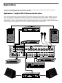
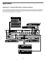
1
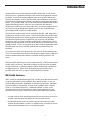
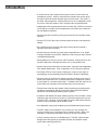
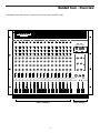
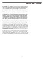
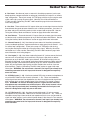
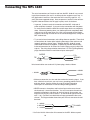
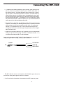
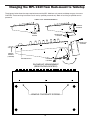
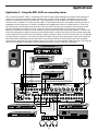
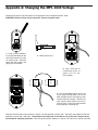
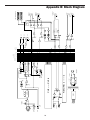
Introduction 1
MPL 1640 Features 1
Guided Tour 3
Overview 3
Channel 4
Main Section 6
Rear Panel 8
Connecting the MPL 1640 10
Balanced connectors 10
Unbalanced connectors 10
Mic connectors 10
Insert connectors 11
Setting Up and Using the MPL 1640 12
Setting the correct gain structure 12
Grounding Techniques 15
Using Bus 3/4 17
Using Pan 18
Using Equalization 19
Using the Auxiliary Sends and Returns 20
Using Channel Inserts 21
Using PFL Solo 22
Changing the MPL 1640 from Rack-mount to
Tabletop 23
Applications 24
Using the MPL 1640 as a main live mixer 24
Using the MPL 1640 as an onstage monitor mixer 25
Using the MPL 1640 as a keyboard submixer 26
Using the MPL 1640 as a recording mixer 27
Appendix A: Changing the MPL 1640 Voltage 28
Appendix B: Block Diagram 29
Specifications 30
Introduction
Congratulations on purchasing the Samson MPL 1640 mixer! In this manual,
we’ll take you on a guided tour through all the features of this powerful and flexible device, and we’ll tell you how to get the most out of the MPL 1640 in your
particular environment. If this is your first mixer, we’re confident that you’ll find
the information in these pages valuable—read them carefully before proceeding
further. If, on the other hand, you’ve had some previous experience with mixers
and dislike reading manuals—well, we have to admit that the 1640 was
designed so you folks can start using it right away—but we still suggest you first
take some time to go through these pages so you can fully understand how
we’ve implemented a number of unique features.
We’ll start with system features and an overview of the MPL 1640, followed by a
guided tour of its front and rear panels. Then we’ll describe how the MPL 1640
should be connected to your existing equipment (including wiring diagrams) and
talk about the important topics of signal flow, gain structure, and grounding
techniques. Next, we’ll cover a number of specific MPL 1640 features (such as
busing, panning, equalization, auxiliary sends and returns, channel inserts, and
soloing) in detail. Finally, we’ll wrap things up with a series of applications notes
describing how you can use the MPL 1640 for both live performance and
recording.
Oh, and one last thing—don’t forget to fill out and mail in the enclosed warranty
card! This will enable you to receive online technical support and will allow us to
send you updated information about this and other Samson products in the
future.
SPECIAL NOTE: Should your unit ever require servicing, a Return Authorization
number (RA) is necessary. Without this number, the unit will not be accepted.
Please call Samson at (516) 932-1062 for a Return Authorization number prior
to shipping your unit. Please retain the original packing materials and, if
possible, return the unit in its original carton and packing materials.
MPL 1640 Features
“MPL” stands for “Microphone/Program/Line” and the name describes the broad
range of signals which can be handled by this powerful console. In fact, the
compact design of the MPL 1640 belies an extraordinary versatility. Add excellent sound quality to the equation, and you’ve got a product which is equally
useful as a live performance mixer, a keyboard submixer, or even a main
recording mixer (you’ll find descriptions of each of these applications at the
conclusion of this manual). Here are some of the MPL 1640’s main features:
• 16 input channels, each providing electronically balanced inputs that can be
used for a broad range of microphone or line-level input sources.
• An electronically balanced main stereo output for connection to a power
amplifier or tape recorder, as well as a secondary Bus 3/4 output for connection to auxiliary equipment such as a monitoring system.
1
Introduction
• 3 auxiliary sends and 3 stereo auxiliary returns (which can be used as 6
monophonic returns). Auxiliary return balance controls allow you to adjust
the relative levels of the left and right inputs for each return. Aux send 1 is
pre-fader and pre-equalizer, making it ideal for use as a headphone or monitor cue mix, while Aux sends 2 and 3 are post-fader and post-equalizer.
• Independent 3-band equalization for each channel, with 15 dB of cut or boost
for low (80 Hz) and high (10 kHz) frequencies and 12 dB of cut or boost for
the mid (800 Hz) frequency.
• Constant level pan controls for placing each channel in the left-right stereo
spectrum.
• Channel PFL (Pre-Fade Listen) switches enable channels to be selectively
soloed.
• Bus switches on each channel allow signal to be muted or routed to a
separate stereo Bus 3/4 output.
• Channel input trim controls are continuously adjustable from +4 to -50 dB,
making it possible to use the MPL 1640 with a wide variety of signal sources
and outboard equipment.
• Center detents for all pan, balance, and EQ controls, making it easy to use
the MPL 1640 even in low-light situations such as live performance.
• Sixteen high-quality short-throw channel faders, along with two independent
Main stereo output faders. Each is detented at its “0” (unity gain) position.
• Peak input LEDs for each channel, showing you when an input signal is
overloading or near overloading (these illuminate 5 dB prior to distortion).
• Channel inserts for twelve of the sixteen channels, enabling you to use outboard signal processors such as outboard equalizers, compressor/ limiters,
or noise gates in a standard “effect loop.” In addition, Main Mix and Bus 3/4
inserts allow you to process the final output signal in the same way.
• The provision of 48v phantom power makes it possible to plug high-quality
condenser microphones directly into the MPL 1640, without the need for
expensive and cumbersome external power supplies.
• A powerful and flexible front-panel metering system, which includes a sevensegment meter that allows you to view at a glance the continuous main output level or PFL solo level. Also included are various LEDs which show the
status of various conditions within the MPL 1640.
• An independent front-panel headphone jack with dedicated volume control.
• The MPL 1640 can be mounted in any standard 19” rack (taking 8 rack
spaces), making it easy to integrate into any existing system. When rackmounted, its connector panel rotates to the rear for easy accessibility.
• Last but certainly not least, an affordable price. The MPL 1640 has been
designed from the ground up to provide versatility and excellent sound
quality without breaking the bank.
2
Guided Tour - Overview
The following illustration shows an overview of the front panel of the MPL 1640:
SAMSON
MPL 1640
1
2
4
3
-10
-10
16 CHANNEL
AUDIO MIXER
-10
6
5
-10
7
-10
-10
9
8
-10
-10
11
10
-10
-10
12
-10
13
14
-10
-10
15
16
-10
-10
-10
0
+4
-50
INPUT TRIM
0
+4
-50
INPUT TRIM
0
+4
-50
INPUT TRIM
0
+4
-50
INPUT TRIM
0
+4
-50
INPUT TRIM
0
+4
-50
INPUT TRIM
0
+4
-50
INPUT TRIM
0
+4
-50
INPUT TRIM
0
+4
-50
INPUT TRIM
0
+4
-50
INPUT TRIM
0
+4
-50
INPUT TRIM
0
+4
-50
INPUT TRIM
0
+4
-50
INPUT TRIM
0
+4
-50
INPUT TRIM
0
+4
-50
INPUT TRIM
0
+4
-50
INPUT TRIM
0
0
0
0
0
0
0
0
0
0
0
0
0
0
0
0
MPL 1640
16 CHANNEL AUDIO MIXER
STERE0
-15
-15
+15
HIGH
+15
HIGH
-12
+12
-15
+15
HIGH
0
0
-12
-15
0
+12
-12
-15
+15
HIGH
-12
-12
+12
-15
+15
HIGH
0
0
+12
-15
+15
HIGH
0
-12
+12
-15
+15
HIGH
-12
-12
+12
-15
+15
HIGH
0
0
+12
-15
+15
HIGH
+15
HIGH
0
-12
+12
-15
0
-12
+12
-15
+15
HIGH
-12
-12
+12
-15
+15
HIGH
-12
+12
-15
+15
HIGH
0
0
0
+12
-15
+15
HIGH
0
-12
+12
-15
+15
HIGH
+15
HIGH
0
-12
+12
-12
+12
+12
MID
MID
MID
MID
MID
MID
MID
MID
MID
MID
MID
MID
MID
MID
MID
0
0
0
0
0
0
0
0
0
0
0
0
0
0
0
0
-15
+15
LOW
−∞
+10
AUX 1
−∞
+10
AUX 2
-15
+15
LOW
−∞
+10
AUX 1
−∞
+10
AUX 2
-15
+15
LOW
−∞
+10
AUX 1
−∞
+10
AUX 2
0
0
+15
LOW
−∞
+10
AUX 1
−∞
+10
AUX 2
0
0
0
-15
-15
+15
LOW
−∞
+10
AUX 1
−∞
+10
AUX 2
0
0
-15
+15
LOW
−∞
+10
AUX 1
−∞
+10
AUX 2
+15
LOW
−∞
+10
AUX 1
0
0
-15
+15
LOW
−∞
+10
AUX 1
+15
LOW
−∞
+10
AUX 1
−∞
+10
AUX 2
-15
+15
LOW
−∞
+10
AUX 1
0
0
0
−∞
-15
0
0
0
0
0
-15
+15
LOW
−∞
+10
AUX 1
0
0
−∞
+10
AUX 2
-15
0
+3
+6
-20
-10
-6
-3
0
+3
+6
POWER
PHANTOM
STEREO AUXILIARY RETURNS
0
−∞
+10
AUX 1
0
−∞
+10
AUX 2
-3
0
−∞
+10
AUX 1
0
−∞
-6
PFL
+15
LOW
0
−∞
+10
AUX 1
0
+10
AUX 2
-15
+15
LOW
0
−∞
+10
AUX 1
−∞
+10
AUX 2
-15
+15
LOW
0
−∞
+10
AUX 1
0
−∞
+10
AUX 2
-15
+15
LOW
0
−∞
0
−∞
+10
AUX 2
-15
+15
LOW
0
0
−∞
+10
AUX 2
-15
-10
RIGHT
0
MID
PFL
-20
LEFT
+20
R
L
RETURN 1 LEVEL
BALANCE
0
−∞
+10
AUX 2
+10
AUX 2
0
0
0
−∞
−∞
+10
AUX 3
0
−∞
+10
AUX 3
0
−∞
+10
AUX 3
0
0
−∞
+10
AUX 3
−∞
+10
AUX 3
0
0
−∞
+10
AUX 3
−∞
+10
AUX 3
0
−∞
+10
AUX 3
0
−∞
+10
AUX 3
−∞
+10
AUX 3
0
0
0
−∞
+10
AUX 3
−∞
+10
AUX 3
0
−∞
+10
AUX 3
0
−∞
+10
AUX 3
0
−∞
+10
AUX 3
−∞
+20
−∞
+20
R
L
BALANCE
RETURN 2 LEVEL
+10
AUX 3
0
R
L
OFF
R
L
PAN
PFL
OFF
ON
OFF
ON
PFL
OFF
ON
R
L
PAN
PAN
PFL
R
L
R
L
PAN
PFL
OFF
ON
OFF
ON
PFL
OFF
ON
R
L
PAN
PAN
PFL
R
L
R
L
PAN
PFL
OFF
R
L
PAN
PFL
OFF
ON
ON
ON
L/R
BUS
BUS
MUTE L / R
MUTE
L/R
3/4
3/4
3/4
PFL
OFF
PFL
OFF
ON
PFL
OFF
ON
R
L
PAN
PAN
PAN
R
L
R
L
R
L
PAN
PFL
OFF
ON
PFL
OFF
ON
PAN
PAN
PAN
PFL
OFF
R
L
R
L
R
L
PAN
PFL
OFF
ON
ON
ON
L/R
BUS
BUS
MUTE L / R
MUTE
L/R
3/4
3/4
3/4
R
L
BALANCE
RETURN 3 LEVEL
PFL
0
L/R
BUS
MUTE
3/4
L/R
BUS
MUTE
3/4
L/R
BUS
MUTE
L/R
3/4
BUS
MUTE
3/4
L/R
BUS
MUTE
3/4
L/R
BUS
MUTE
3/4
BUS
MUTE
L/R
BUS
MUTE
L/R
3/4
BUS
L/R
MUTE
3/4
BUS
MUTE
3/4
L/R
BUS
MUTE
3/4
BUS
MUTE
−∞
2
1
PEAK
PEAK
3
4
PEAK
PEAK
6
5
PEAK
PEAK
8
7
PEAK
PEAK
9
PEAK
10
PEAK
PEAK
13
12
11
PEAK
PEAK
14
PEAK
15
PEAK
16
0
+15
3-4
LEVEL
10
HEADPHONES
PEAK
L
MAIN
+15
+15
+15
+15
+15
+15
+15
+15
+15
+15
+15
+15
+15
+15
+15
+15
0
0
0
0
0
0
0
0
0
0
0
0
0
0
0
0
-∞
-∞
-∞
-∞
-∞
-∞
-∞
-∞
-∞
-∞
-∞
-∞
-∞
-∞
dB
dB
dB
dB
dB
dB
dB
dB
dB
dB
dB
-∞
-∞
dB
dB
dB
Input Channels
dB
R
dB
Main Section
3
Guided Tour - Channel
Let’s start our guided tour by examining the various controls provided by each
channel:
1
-10
1
0
+4
-50
INPUT TRIM
0
-15
1: Input Trim (black) - This knob determines the input level of the connected
mic or line signal. Continuously adjustable from +4 dB to -50 dB, the input trim is
at unity gain (no boost or cut) when set to the 0 position. The input signal is
boosted when the knob is turned to the right of 0 and attenuated when turned to
the left of 0. For information on how to properly set this for each channel, see the
section on page 12 entitled “Setting The Correct Gain Structure.”
+15
HIGH
0
-12
2
+12
MID
0
-15
+15
LOW
−∞
+10
AUX 1
−∞
+10
AUX 2
−∞
+10
AUX 3
0
0
3
2: Equalizer (blue) - These knobs determine the amount of boost or attenuation
in each of three frequency areas. The “High” and “Low” frequency knobs provide
15 dB of cut or boost at 10 kHz and 80 Hz, respectively, with shelving-type
control. The “Mid” frequency knob provides 12 dB of cut or boost at 800 Hz, with
a bell (peaking) curve. A center detent in each knob (at the 12 o’clock position)
indicates no boost or attenuation (that is, flat response). As each knob is turned
clockwise from the center detent position, the frequency area is boosted; as it is
turned counterclockwise from the center detent position, the frequency area is
attenuated. For more information on the application of EQ, see the “Using
Equalization” section on page 19 of this manual.
0
4
R
L
PAN
OFF
PFL
5
ON
L/R
BUS
MUTE
3/4
6
1
7
PEAK
+15
0
-∞
dB
8
3: Auxiliary sends (light gray) - These knobs allow you to route signal to any of
the MPL 1640’s three monophonic auxiliary outputs. These are typically used to
create submixes (for example, a monitor mix or headphone cue mix) or to feed
signal from single or multiple channels to outboard effects devices. At the 0 position, the send signal is routed with unity gain (that is, no boost or attenuation).
As each knob is turned clockwise from the 0 position, the signal is boosted; as it
is turned counterclockwise from the 0 position, it is attenuated. At the fully
counterclockwise “-∞” position, the send signal is infinitely attenuated—that is,
no signal is routed. At the fully clockwise “+10” position, the send signal is routed
with 10 dB of gain. Auxiliary send 1 is always pre-fader; that is, the level of the
send signal is determined solely by the channel’s input trim and is unaffected by
its fader position and EQ settings. Auxiliary sends 2 and 3 are post-fader; that is,
the level of the send signal is determined by the channel’s input trim, its EQ
settings, and the position of its fader.
4: Pan (white) - This knob allows you to place each channel’s signal anywhere
in the left-right stereo spectrum, while keeping the overall signal level constant.
When the knob is placed at its center (detented) position, the signal is sent
equally to both left and right outputs. When moved left of center, less signal is
sent to the right output (making the sound appear left of center) and when moved
right of center, less signal is sent to the left output (making the sound appear
right of center). To route a signal hard left or right, place the pan knob either fully
counterclockwise or fully clockwise. See the “Using Pan” section on page 18 of
this manual for more information.
5: PFL switch (gray) - When pressed in, the channel is soloed in PFL (Pre-Fade
Listen) mode, affecting headphone monitoring only. For more information, see
the section on page 22 entitled “Using PFL Solo.”
4
Guided Tour - Channel
6: Bus switch (gray) - When up, the channel’s signal is routed to the Main L/R
faders (as described on page 7) and then on to the MPL 1640 Main Mix output
jacks (as described on page 8). When pressed in, the channel’s signal is
removed from the Main L/R output and is instead routed to the 3/4 Level knob
(as described on page 6) and then to the 3L/4R output jacks (as described on
page 8). If you don‘t have anything connected to the MPL 1640 Bus 3/4 output
jacks, this switch can be used for channel muting. See the “Using Bus 3/4”
section on page 17 for more information.
7: Peak LED (red) - This warning light indicates an overload situation. It lights
whenever a channel’s signal is 5 dB short of clipping. To stop it from lighting
(and to eliminate the accompanying sonic distortion), turn down the channel’s
Trim knob (see #1 on the previous page) or reduce the amount of equalization
boost. See the “Setting the Correct Gain Structure” and “Using Equalization”
sections on pages 12 and 19 for more information.
8: Channel fader (gray with a blue line) - This linear slider determines the signal
level being sent to the main output as well as affecting the signal level being
routed to Aux sends 2 and 3 (which are post-fader; Aux 1 is always pre-fader).
In practice, you will use the channel faders to continuously adjust the levels of
the various signals being blended together by the MPL 1640. The detented “0”
position of the fader indicates unity gain (no level attenuation or boost). Moving
the fader down from the “0” position (towards “-∞”) causes the signal to be attenuated (at the very bottom, it is attenuated infinitely—in other words, there is no
sound). Moving it up from the “0” position (towards “+15”) causes the signal to
be boosted by as much as 15 dB.
For best signal-to-noise ratio, all faders for channels carrying signal should generally be kept at or near the “0” detented position. Channels that are unused
should have their faders kept all the way down at their "-∞" (minimum) level. See
the “Setting the Correct Gain Structure” section on page 12 for more information.
5
Guided Tour - Main Section
MPL 1640
16 CHANNEL AUDIO MIXER
STERE0
PFL
-20
-10
-6
-3
0
+3
-20
-10
-6
-3
0
+3
+6
LEFT
RIGHT
PFL
+6
1
POWER
PHANTOM
2: Meter LEDs - These show the status of various conditions within the MPL
1640. The bottom left LED (labeled “PFL”) lights steadily red whenever one or
more channels is soloed. The bottom center LED (labeled “Phantom”) lights
steadily red when Phantom power is being supplied to all mic connectors (see #1
on page 8 of this manual for more information). The bottom right LED (labeled
“Power”) lights steadily red whenever the MPL 1640 is powered on.
2
STEREO AUXILIARY RETURNS
0
−∞
+20
R
L
RETURN 1 LEVEL
BALANCE
4
3
0
−∞
+20
−∞
+20
R
L
BALANCE
RETURN 2 LEVEL
0
R
L
BALANCE
RETURN 3 LEVEL
6
0
5
1: Meter - This seven-segment bar meter shows the continuous output level of
the Main L/R stereo output. For optimum signal-to-noise ratio, try to adjust all
levels so that program material is usually at or around 0 VU, with occasional but
not steady excursions to the red +3 or +6 segments. See the “Setting the
Correct Gain Structure” section on page 12 for more information.
−∞
0
+15
3-4
LEVEL
7
10
3: Stereo Auxiliary Return Level (green) - These knobs determine the input
level of signal arriving via the MPL 1640’s three stereo Auxiliary returns. Each
return is at unity gain (no boost or attenuation) when set to the 0 position. The
input signal is boosted when the knob is turned to the right of 0 and attenuated
when turned to the left of 0. When turned fully clockwise (to the “+20” position),
the return signal is boosted by 20 dB; when turned fully counterclockwise (to the
“-∞” position), the return signal is infinitely attenuated—that is, there is no sound.
For information on how to properly set these, see the sections on pages 12 and
20 entitled “Setting the Correct Gain Structure” and “Using the Auxiliary Sends
and Returns.”
HEADPHONES
L
MAIN
R
+15
0
-∞
dB
8
4: Stereo Auxiliary Return Balance (dark gray) - These knobs determine the
relative levels of the left and right input signals connected to the MPL 1640’s
three stereo Auxiliary returns. When the knob is placed at its center (detented)
position, both left and right input signals for that Aux return are at equal strength.
When moved left of center, the left input signal remains at the same strength but
the right input signal is attenuated; when the knob is moved right of center, the
right input signal remains at the same strength but the left input signal is attenuated. When placed fully counter-clockwise, only the left input signal is heard
(panned hard left); when placed fully clockwise, only the right input signal is
heard (panned hard right). These “radical” positions are useful when you are
using a stereo Aux return as two mono returns—see the “Using the Auxiliary
Sends and Returns” section on page 20 for more information.
When only the left input of an Aux return is connected, its Balance knob functions as a constant level Pan control, allowing you to continuously place the
incoming signal anywhere in the left-right stereo field.
5: 3/4 Level (green) - This knob determines the final output level of the Bus 3/4
signal. We made this knob extra big so you won’t miss it even under low-light
performance conditions. Signals from all channels that have their Bus
switch (see page 5) set to the “3/4” position are routed here prior to being sent to
the rear panel 3/4 output jacks (as described on on page 8). The center detented “0” position of the knob indicates unity gain (no level attenuation or boost).
Moving the knob counterclockwise from the “0” position (towards “-∞”) causes
the signal to be attenuated (at the fully counterclockwise position, it is attenuated
infinitely—in other words, there is no sound). Moving the knob clockwise from
the “0” position (towards “+15”) causes the signal to be boosted by as much as
15 dB. For more information, see the “Using Bus 3/4” section on page 17 of this
manual.
6
Guided Tour - Main Section
6: Headphones control (black) - This knob sets the level of the signal sent to
the headphone jack (see #7 below). WARNING: To avoid possible damage
to connected headphones (or, worse yet, to your ears!), always turn this all
the way off (to the fully counterclockwise “0” position) before plugging in a
pair of headphones—then raise the level slowly while listening. The
Headphones control has no effect on the final Main Mix or Bus 3/4 output levels.
7: Headphone jack - Connect any standard stereo headphones to this jack (via
a standard 1/4” TRS plug) for private monitoring of the main stereo output. The
built-in MPL 1640 headphone preamp delivers 150 mw at 30 ohms.
8: Main L/R Faders (white with blue line) - These linear sliders determine the
relative level of the two Main Left/Right outputs just prior to being sent to the rear
panel Main Mix output jacks (as described on page 8). The “0” (detented)
position of each fader indicates unity gain (no level boost or attenuation).
Moving the fader below this position (towards the “-∞” dB position) causes the
signal to be attenuated (at the very bottom, it is attenuated infinitely—in other
words, there is no sound). Moving it above this position (towards the “+15”
position) causes the signal to be boosted by as much as 15 dB.
For best signal-to-noise ratio, both Main L/R faders should generally be kept at
or near the detented 0 level. See the “Setting The Correct Gain Structure”
section on page 12 of this manual for more information.
7
Guided Tour - Rear Panel
5
1
6
14
CAUTION
!
RISK OF ELECTRIC SHOCK
DO NOT OPEN
13
SERIAL
NUMBER
ASSEMBLED IN R.O.K.
PHANTOM
AVIS:
XLR
RISQUE DE CHOC ELECTRIQUE
NE PAS OUVRIR.
DO NOT EXPOSE THIS EQUIPMENT
TO RAIN OR MOISTURE.
1 GND
2 +
3 -
MAIN MIX OUT
(BALANCED 600Ω + 4dB)
ON
CH 16
CH 15
CH 14
CH 13
CH 10
CH 11
CH 12
SAMSON MPL 1640
TIP RING SLEEVE
16 CHANNEL
AUDIO MIXER
TIP
+
RING SLEEVE GND
SAMSON TECHNOLOGIES CORP., NEW YORK, U.S.A.
CH 8
CH 9
CH 7
CH 5
CH 6
CH 4
CH 2
CH 3
CH 1
L
2
1
2
3
P
O
OFF
E
R
ON
W
12
2
1
3
1
2
2
1
3
3
2
1
3
2
1
3
1
2
3
2
1
1
2
3
3
1
3
(BALANCED - 50dB TO + 4dB)
MIC INPUT
AUX OUT
(UNBAL.2KΩ +4dB)
BUS INSERT
LINE INPUT
(BALANCED 10 KΩ - 40dB TO + 4dB)
L
OFF
R
3L - 4R(UNBAL.2KΩ +4dB)
MAIN MIX
3L - 4R
AUX 3
AUX 2
AUX 1
CH 16
CH 15
CH 14
CH 13
CH 12
CH 11
CH 10
CH 9
CH 8
CH 7
CH 6
CH 5
CH 4
CH 3
CH 2
CH 1
115
R
R
~115V /230V
50/60Hz 42W
2
3
4
7 8
9
AUX 3
L
R
R
L
AUX 2
AUX RETURN (UNBAL.2KΩ + 4dB)
AUX 1
L
CHANNEL INSERT
(TIP RETURN - RING SEND)
11
10
1: Phantom switch - When this switch is turned on, the MPL 1640 delivers 48 volts of
phantom power to pins 2 and 3 of all XLR microphone connectors (channels 1 - 10).
WARNING: Only turn this on or off with the MPL 1640 powered down. Before turning phantom power on, be sure to disconnect all non-microphone signal sources (such as
direct injection boxes) from the XLR mic jacks. Although phantom power will have no
adverse affect on connected dynamic microphones, it should be used only when one or
more condenser microphones are connected to the MPL 1640 (refer to the owners manual of your microphone to determine whether or not it requires 48 volts phantom power).
If you’re not completely certain that one or more connected mics require 48 volts
phantom power, leave this switch OFF.
2: Power switch - This is what you use to turn the MPL 1640 on and off. To avoid
potential damage to your speakers, turn the mixer on before you turn on any connected
power amps—and turn it off after the power amps are turned off.
3: AC Input - Connect the supplied standard 3-pin “EEC” plug here.
4: Fuse sled - Fuse ratings are 1 amp for 115 V usage and .5 amp for 230 volt usage.
See Appendix A on page 28 for more information.
5: Main Mix Out (L,R) - These are the MPL 1640’s main outputs. You’ll usually use
these to connect the MPL 1640 to a power amplifier or to a tape recorder. These jacks
are electronically balanced, so use balanced three-conductor cabling and 1/4" TRS plugs
wherever possible (unbalanced two-conductor plugs can also be inserted into these jacks,
but you’ll get better signal quality and less noise and hum if you use balanced lines). See
the “Connecting the MPL 1640” section on page 10 for more information.
6: 3L/4R Out - These are the MPL 1640’s secondary outputs. The 3/4 Out jacks are
unbalanced, accepting standard two-conductor 1/4" plugs. For this reason, it is generally
preferable to use the Main Mix outputs when only two outputs are required. See the
“Using Bus 3/4” section on page 17 for more information.
7: Main Mix Insert (L,R) - Use these to insert an external in-line effects processor (such
as outboard equalizer, compressor/limiter or noise gate) into the Main Mix output in an
“effects loop” configuration. These jacks accept 1/4" TRS plugs, with the ring carrying the
send signal and the tip carrying the return signal. Normally, this will be connected to a
Y-cable; see the “Connecting The MPL 1640” section on page 10 for more information
and a wiring diagram.
8
Guided Tour - Rear Panel
8: Bus Insert - Use these to insert an external in-line effects processor (such as outboard equalizer, compressor/limiter or noise gate) into the Bus 3/4 output in an “effects
loop” configuration. These jacks accept 1/4" TRS plugs, with the ring carrying the send
signal and the tip carrying the return signal. Normally, this will be connected to a
Y-cable; see the “Connecting The MPL 1640” section on page 10 for more information
and a wiring diagram.
9: Aux Outs - These unbalanced 1/4" outputs allow you to route signal from each of the
three discrete Aux sends to external devices such as effects processors. Aux send 1 is
pre-fader and pre-EQ, while Aux sends 2 and 3 are post-fader and post-EQ. See the
“Using the Auxiliary Sends and Returns” section on page 20 for more information.
10: Aux Returns - These unbalanced 1/4" inputs allow you to route signal from external devices such as effects processors to any of the three stereo Aux Returns. See the
“Using the Auxiliary Sends and Returns” section on page 20 for more information.
11: Channel Inserts (1 - 12) - Use these to insert external in-line effects processors
(such as outboard equalizers, compressor/limiters or noise gates) into channels 1 - 12 in
an “effects loop” configuration. These jacks accept 1/4” TRS plugs, with the ring
carrying the send signal and the tip carrying the return signal. Normally, this will be
connected to a Y-cable; see the “Connecting The MPL 1640” section on page 10 for
more information and a wiring diagram.
12: Line Inputs (1 - 16) - Use these standard balanced 1/4" jacks to connect line-level
sources such as synthesizers, drum machines, CD players, tape decks, or effects
processors to any of the MPL 1640’s input channels. All channel line input jacks are
electronically balanced, so you should use balanced three-conductor cabling and plugs
wherever possible (unbalanced two-conductor plugs can also be inserted into these
inputs, but you’ll get better signal quality and less outside noise and hum if you use
balanced lines). See the “Connecting The MPL 1640” section on page 10 for more
information. WARNING: Do not connect a channel’s line input if you already have
something connected to its mic input; each channel is designed to accept only
one or the other.
13: XLR Mic Inputs (1 - 10) - Use these standard XLR jacks to connect microphones to
any of the MPL 1640’s first ten channels (channels 1 - 10). These are intended to
accept signal from low-level, low-impedance mics but can also be used for signal from
other sources (such as direct injection boxes) if the channel’s Trim control is turned
down. WARNING: Do not turn Phantom power on if signal sources other than
microphones are connected to any of these inputs. Also, do not connect a channel’s mic input if you already have something connected to its line input; each
channel is designed to accept only one or the other.
14: 1/4" Mic Inputs (11 - 16) - Use these standard balanced 1/4" jacks to connect
microphones to any of the MPL 1640’s last six channels (channels 11 - 16). These are
intended to accept signal from low-level, low-impedance mics but can also be used for
signal from other sources (such as direct injection boxes) if the channel’s Trim control is
turned down. WARNING: Do not connect a channel’s mic input if you already have
something connected to its line input; each channel is designed to accept only
one or the other.
9
Connecting The MPL 1640
The actual connections you’ll make to and from the MPL 1640 will vary according to the environment you use it in and the particular equipment you have. In
the “Applications” sections at the conclusion of this manual (pages 24 - 27),
you’ll find some suggested setups. Here we present a few basic rules concerning MPL 1640 connections that will apply in pretty much all situations:
• In general, it’s best to make all connections with the MPL 1640 and all
power amplifiers turned off. If you must make connections with the power
on, make sure that both the Main Mix and 3/4 output levels are completely
down. Whenever powering down, turn both output levels completely down
and then turn off all power amps first. Wait a few seconds for their power
supplies to discharge and then turn off all connected equipment, turning the
MPL 1640 off last.
• Try to use balanced connectors and cabling wherever possible. These kind
of connections do a better job of rejecting extraneous noise and hum and
generally provide a cleaner signal. Although the MPL 1640 will accept
unbalanced connectors throughout, it specifically provides electronically
balanced connectors for all sixteen mic and line inputs and for its Main Mix
outputs. The wiring diagram below shows how 1/4" TRS (Tip/Ring/Sleeve)
plugs should be wired for use with these inputs and outputs:*
SLEEVE
TIP
RING
TIP +
GROUND
RING -
Unbalanced cables use standard 1/4" phone plugs, wired as follows:
+ SIGNAL
+ SIGNAL
GROUND
GROUND
• Make one connection at a time and then monitor the incoming signal. If you
hear a distinct hum or buzz, you may have a grounding problem with that
particular device. See the section on page 15 entitled “Grounding
Techniques” for information on how to avoid grounding problems.
• NEVER connect a microphone and line level input to the same channel
simultaneously—use one or the other. You can have some channels connected to microphones and others to line level signals (for example, you
might want to plug mics into channels 1 - 6 and line level signals into channels 7 - 10)—just don’t have both kinds of inputs connected to the same
channel. The diagram below shows how your XLR mic connectors should
be wired:*
3 - SIGNAL
1 GROUND
2 + SIGNAL
TO MIXER
* You’ll also find this information silk-screened on the MPL 1640 rear panel.
10
Connecting The MPL 1640
• In addition to the sixteen monophonic input channels, there are three “hidden” (or at least not so obvious) stereo inputs to the MPL 1640; these are
the Auxiliary returns.* Use these whenever you want to bring in a stereo
signal that will not need to be equalized. Also bear in mind that the three
stereo Auxiliary returns can also be used as six monophonic returns (with
the Aux return Balance controls giving you the ability to adjust the relative
levels of the left/right inputs). For example, if you’re using the MPL 1640 in
live performance to drive a mono PA system, you may not need to take the
stereo returns from outboard effects processors.
• Because Aux 1 is pre-fader, you should use it only where a pre-fade mix is
required. For example, in a recording situation, Aux 1 is optimum for headphone cueing or for driving a secondary monitor (such as a studio room
monitor). In live performance, Aux 1 can be used to route signal to an
onstage monitor system so that the signal the performers hear is independent of the house mix.
• Signals that are likely to require “in-line” processing (such as compression/
limiting or expansion/noise gating) should be connected to channels 1 - 12,
since these channels provide an insert connection.
Insert cables (sometimes called “Y-cables”) should terminate in standard 1/4”
TRS jacks (tip to return and ring to send), wired as follows:**
SLEEVE
TIP RETURN
GROUND
RING SEND
TIP
RING
* The MPL 1640 Aux returns are hardwired to the Main Mix outputs; there is no
provision for routing their signal to the Bus 3/4 outputs.
** You’ll also find this information silkscreened on the MPL 1640 rear panel.
11
Setting Up and Using the MPL 1640
Setting up your MPL 1640 is a simple procedure which takes only a few minutes:
MAIN MIX OUT
1. Remove all packing materials (save them in case of need for future service)
and decide where the unit is to be physically placed—it can be used on a
tabletop or mounted in any standard 19” rack, requiring 8 rack spaces.
(BALANCED 600Ω + 4dB)
L
SAMSON
SERVO - 240
2. Before even plugging the unit into an AC socket, begin by connecting the
MPL 1640 Main Mix outputs (or secondary 3L/4R outputs) into a switchedoff power amp and the amp into loudspeakers. It is never a good idea to
power up any amplifier that is not connected to loudspeakers.
R
3. Next, make all signal connections to the mic or line inputs of the various
channels and to the MPL 1640’s Aux sends and returns and insert points as
required. WARNING: Do not connect a channel’s line input if you already
have something connected to its microphone input, or vice versa; each
channel is designed to accept only one source or the other.
115
4. Bring all channel faders and the Main L/R faders completely down (to their
“-∞” setting) and turn the 3/4 Level knob fully counterclockwise (to its
“-∞” setting). Then connect the EEC main power cord and plug the MPL
1640 into any grounded AC socket.
ON
P
O
W
E
R
OFF
5. Press the MPL 1640’s rear-panel Power switch. Once power is received,
the “Power” LED in the meter section will light up.
Setting the Correct Gain Structure
You’re now ready to establish the correct gain structure—the key to getting the
best performance from the MPL 1640, or from any mixer, for that matter. This is
a simple procedure that ensures optimum input and output levels so that no
unnecessary noise (caused by too low a signal) or overload distortion (caused by
too high a signal) is created. Here’s a step-by-step description of how to do so:
a Turn off the MPL 1640 and all connected power amplifiers. Set all power
amplifier volumes to minimum. On the MPL 1640, bring all channel faders
down to the bottom-most “-∞” position, and set both Main L/R faders to their
center detent “0” position. If any devices are connected to the secondary
3L/4R outputs, turn the 3/4 Level knob fully counterclockwise (to its “-∞”
setting).
b. Set all channel input trim knobs to their fully counterclockwise (+4) position.
c. Set all channel equalizer and pan knobs as well as all three Aux return
balance knobs to their center detent “0” positions.
d. Set all channel Aux send knobs and all three stereo Aux return level knobs
to their fully counterclockwise (“-∞”) position.
e. Turn on all devices connected to channel line inputs and Aux returns and
set their output level controls to unity gain or, if there is no unity gain indicated on their output control, to maximum. If you’ve got outboard effects
processors connected to MPL 1640 Aux returns, make sure they are sending completely “wet” (processed) signal, with no “dry” (unprocessed) signal
mixed in.
12
Setting Up and Using the MPL 1640
f. If any condenser microphones are connected to the MPL 1640, turn on the
Phantom switch.* Then turn on the MPL 1640—the Power LED in the
meter section will light up. Finally, turn on the power amplifier.
g. Play an instrument connected to one of the MPL 1640’s line inputs** and,
while doing so, raise the corresponding channel fader to the “0” position.
You should see the segment meter begin to move—adjust the input trim
control for that channel so that the “0” segment lights frequently and the
“+3” segment lights only occasionally. If the incoming signal seems too hot
even with the input channel trim all the way at its minimum (+4) setting, you
may need to lower the output level of the instrument, though this will rarely
occur. Conversely, if the signal is too low even with the input channel trim
all the way up, something's definitely wrong: in all likelihood, the connecting
audio cable is faulty.
h. Once you’ve set the optimum level in step (g) above, continue playing the
instrument and slowly raise the power amplifier volume until you get the
level you want to hear.
i. Repeat step (g) above for each instrument connected to the MPL 1640
channel line inputs.
j. The procedure for setting optimum microphone levels is virtually identical;
sing or speak into the mic at the level you expect to use in performance
while slowly raising the fader for that channel to its “0” position. Then adjust
the input trim control for that channel while watching the meter. You should
expect that microphone inputs will require rather more in the way of input
trim boost than line inputs.
k. If you have any outboard signal processors connected to the Aux send and
return jacks on the rear panel, follow this step. Because outboard effects
processors can sometimes be quite noisy, it’s particularly important to maximize the amount of signal being sent to them via the MPL 1640 Aux sends.
The idea is to drive these devices as hot as possible (short of overloading
them) and to then use the corresponding Aux return level to carefully adjust
the amount of processed signal being blended with the dry signal. To set
optimum Aux send levels, use a channel that has already had its gain structure adjusted in step (g) or (j) above. Turn all three Aux send knobs for that
channel to their “0” (unity gain) position and then play the instrument (or
sing into the microphone) connected to that channel. Adjust the input levels
of connected outboard effects processors so that their meter shows incoming signal normally in the 0 VU range (with just occasional higher excursions). Then it’s time to optimize the Aux return levels. While continuing to
play your instrument (or continuing to sing into the microphone), slowly raise
each Aux return level control until you hear the desired amount of
processed signal added to the dry signal. For more information, see the
“Using the Auxiliary Sends and Returns” section on page 20 of this manual.
* CAUTION: Before turning phantom power on, be sure to disconnect all nonmicrophone signal sources (such as direct injection boxes) from the XLR
mic jacks (channels 1 - 10).
** If you're using an instrument such as electric guitar or bass, we recommend
that you connect it to the MPL 1640 with a direct injection box to ensure correct impedance.
13
Setting Up and Using the MPL 1640
l. The gain structure is now correctly set—you’ve optimized the level of all signals coming into and out of the MPL 1640, and the end result will be minimum noise and distortion and maximum clean sound. You’ll now find that
the majority of your mixes can be accomplished with most channel faders
and both Main L/R faders at or near their 0 (unity gain) position and that the
channel peak LEDs rarely if ever light (remember, if they do light, it means
that something is distorting!). If you need to make adjustments to the overall level, use the volume control of your power amplifier.
Because this procedure sets the optimum input gain of all channels, it also
sets the correct gain structure when using the MPL 1640’s alternative Bus
3/4 outputs. Following this procedure, if you opt to route a channel’s signal
to the Bus 3/4 outputs (by pressing in that channel’s Bus switch), simply set
the main Bus 3/4 level knob to its detented 0 (unity gain) position for best
signal-to-noise ratio.
If you encounter difficulty with any aspect of setting up or using your MPL 1640,
you can call Samson Technical Support (516-932-1062) between 9 AM and
5 PM EST.
14
Grounding Techniques
Hum and buzz are the biggest enemies you face when interconnecting a large
number of different pieces of equipment to a central audio mixer. This is
because each piece of equipment may operate at a marginally different voltage
(this difference is called potential) and, when two devices at slightly different
potential are physically connected with audio cabling, the end result can be
nasty, extraneous noise (mind you, connecting two devices at very different
potential can result in a major electrical shock!).
However, there are several steps you can take to avoid grounding problems.
First, assuming you have an isolated electrical circuit that can handle the electrical demands of your mixer and all connected audio equipment (these needs will
usually be modest), you should always plug your mixer and all connected equipment into the same circuit. If possible, nothing else but this equipment should be
connected to that circuit. If you can’t do this, at least avoid plugging your mixer
and audio equipment into the same circuit that is already powering things like
heavy machinery, air conditioners, heaters, refrigerators, washing machines,
neon signs or fluorescent light fixtures. One particular culprit that will almost certainly create problems is the standard light dimmer (the kind that uses silicon
controlled rectifiers). Where low-level lighting is desired, use incandescent fixtures with autotransformer-type dimmers (sometimes called Variacs) instead—
these cost considerably more than the standard dimmer you’ll find at your local
hardware store, but are well worth the extra expense.
Three-prong plugs (such as the one used by the MPL 1640) should always be
used as is; don’t use adapters to lift the ground (unless you’re using a “star
ground network”—see below). If you hear hum or buzz from a device that uses
a two-prong plug (or an external two-prong AC/DC adapter), you can try reversing the plug in the socket. If that doesn’t work, you may need to physically
ground that device’s chassis by connecting a wire (called a strap) from it to a
grounded piece of metal such as rack ears. Some pieces of equipment have a
screw-type ground post to which the strap can be connected; if not, you can
attach some kind of metallic binding post to the case itself. If you are using rackmounted audio devices and are experiencing hum or buzz, there's a simple test
to determine the source of the problem: while keeping all devices powered on
and connected with audio cabling, physically remove each device, one by one,
from the rack. If the hum disappears when a particular device is removed, you'll
know that that device is the culprit.
We also recommend that you use balanced audio cabling and connectors wherever possible. The MPL 1640 provides electronically balanced inputs for all
channel mic and line inputs as well as for its Main Mix outputs. The wiring diagram in the “Connecting The MPL 1640” section of this manual (page 10) shows
how 1/4” TRS (Tip/Ring/Sleeve) connectors should be wired for use with these
inputs and outputs.
In addition, you can minimize possible interference by planning your audio, electrical, and computer cable runs so that they are as far apart from one another as
possible and so they don’t run parallel to one another. If they have to cross, try
to ensure that they do so at a 90° angle (that is, perpendicular to one another).
In particular, try to keep audio cabling away from external AC/DC adapters.
15
Grounding Techniques
If you’re using the MPL 1640 in a fixed location such as a recording studio, you
may want to invest the time and money into creating a star ground network. This
is by far the best technique for avoiding grounding problems. It involves using a
formidable ground source such as a cold water pipe or a copper spike driven into
the earth. A thick grounding cable is connected to that source and is then
brought to a central distribution point; from there, individual cables are connected
to each piece of equipment. This setup also requires that you lift the ground plug
of all three-prong AC connectors, so there is the possibility of danger if it is done
incorrectly. We strongly recommend that you contract with a qualified professional to carry out this or any kind of electrical work.
Another, less common problem you may encounter is that of oscillation (a ringing
tone), which, apart from being annoying, is potentially dangerous to your speakers. This is generally caused either by poor outside wiring or by returning a signal out of phase (most commonly from an outboard signal processor). If audible
oscillation occurs, try isolating each input signal (by muting all other inputs or by
using the PFL soloing function). If one signal alone is causing the problem, you
should be able to eliminate the oscillation by reversing that signal’s phase (many
signal processors have a switch that allows you to do this).
16
Using Bus 3/4
In addition to the Main Mix stereo output, the MPL 1640 provides two independent bus outputs (Bus 3/4).* A “bus” is simply a pathway through which a signal
can be routed. The provision of these secondary outputs makes it possible for
you to create two mixes simultaneously, so that some channels send signal to
the Main Mix output jacks (via the Main L/R faders) while other channels send
signal to the Bus 3 and 4 output jacks.**
For example, when using the MPL 1640 with a two-track digital or analog tape
recorder, you might want to connect the Main Mix outputs to the tape inputs
while connecting the Bus 3/4 outputs to the inputs of a stereo power amplifier.
If you then connect the tape outputs to two channels routed to Bus 3/4 (by
pressing in their Bus switches), you can then use the Main L/R faders to control
the signal level going to tape while using the Bus 3/4 level knob to control the
playback volume (you’ll want to set the tape recorder to monitor input signal
while recording). See the “Applications” section on page 24 of this manual for
more information.
If no equipment is connected to the rear panel Bus 3/4 output jacks, you can use
the MPL 1640 Bus switches to mute particular channels (that is, remove them
temporarily from the overall mix without having to change their fader position).
To do this, all you have to do is press in that channel’s Bus switch; when you do
so, the signal will be rerouted to the Bus 3/4 output jacks (which are not
connected to anything) and will be removed from the Main Mix you hear. To
restore the signal (that is, unmute it), all you have to do is press that channel’s
Bus switch again—since its fader hasn’t been moved, the sound will come back
at the same level as before.
* When only two outputs are required, the Main Mix outputs are preferable to the
Bus 3/4 outputs since they provide electronically balanced jacks.
** A channel cannot be routed to both the Main Mix and Bus 3/4 output jacks
simultaneously. Note also that the MPL 1640 Aux returns are hardwired to the
Main Mix outputs; there is no provision for routing their signal to the Bus 3/4
outputs.
17
MAIN MIX OUT
(BALANCED 600Ω + 4dB)
L
R
3L - 4R(UNBAL.2KΩ +4dB)
0
−∞
+15
3-4
LEVEL
L/R
3/4
BUS
MUTE
Using Pan
R
L
PAN
The final Main output of the MPL 1640 is stereo—that is, there are two discrete
Main Mix output jacks, labeled “left” and “right,” which will normally route signal
(via a power amplifier) to two discrete speakers.* Because of this, you will usually be working with a stereo field that ranges from hard left to hard right. The Pan
control in each channel allows you to place each individual sound at any point
within this left-right field, while keeping the overall level constant.
You can use stereo panning creatively in a variety of ways: For example, you
might want to have guitars coming from one speaker and keyboards from another, or you might use panning to “spread” the signal from a piano miked with two
microphones—one over the bass notes (panned left) and the other over the treble notes (panned right). By turning a Pan knob while a signal is present, the
sound appears to move in space (a process known as dynamic panning)—this
can be particularly effective when applied to sound effects.
In live performance, you may want to resist the temptation to pan anything completely hard left or right, since some members of the audience not seated in the
center of the venue may miss some signal altogether. In these circumstances,
you’re best to use modest panning, with signals routed no further than the 9
o’clock and 3 o’clock positions.
R
L
BALANCE
In the stereo Auxiliary return section, the Balance control allows you to adjust the
relative levels of the signals arriving at the left and right inputs. In Aux returns
where both inputs are connected, the left signal is automatically panned hard left
and the right signal is automatically panned hard right. The Balance knob controls the relative levels of the paired input signals. When the knob is placed at its
center (detented) position, both the left and right signals are at equal strength.
When moved left of center, the left input signal remains the same but the right
input signal is attenuated; when the knob is moved right of center, the right input
signal remains the same but the left input signal is attenuated. When placed
fully counterclockwise, only the left input is heard (panned hard left); when
placed fully clockwise, only the right input is heard (panned hard right).
If you connect different monophonic devices (such as effects processors) to both
the left and right inputs of an Aux return, you can use the Aux Balance control to
blend the relative contribution of each. If you turn the Balance knob fully counterclockwise, you’ll hear only the device connected to the left Aux input; if you
turn it fully clockwise, you’ll hear only the device connected to the right Aux input.
For more information, see the “Using the Auxiliary Sends and Returns” section
on page 20 of this manual.
* You can, of course, also use the MPL 1640 monophonically—simply route the
same signal to both the left and right outputs.
18
Using Equalization
One of the most exciting aspects to using a mixer such as the MPL 1640 is having the ability to shape a sound, using a process called equalization. But there
are few areas of sound engineering more misunderstood than equalization, and,
just as good EQ can really help a sound, bad EQ can really hurt it, so read on...
Every naturally occurring sound consists of a broad range of pitches, or frequencies, combined together in a unique way. This blend is what gives every sound
its distinctive tonal color. The EQ section in a mixer allows you to alter a sound
by boosting or attenuating specific frequency areas. The MPL 1640 provides
independent three-band equalization controls for each of its sixteen channels.
The “High” knob affects frequencies in the 10 kHz area; the “Mid” knob affects
frequencies in the 800 Hz area; and the “Low” knob affects frequencies in the
80 Hz area. Each EQ knob is labeled with the maximum amount of cut or boost
provided (±15 dB in the case of high and low frequencies, and ±12 dB in the
case of the mid frequency).
We provided these particular frequency areas because they have maximum
impact on musical signals—that’s why they are sometimes known as “sweet
spots.” When an EQ knob is in its center detented position (“0”), it is having no
effect. When it is moved right of center, the particular frequency area is being
boosted; when it is moved left of center, the frequency area is being attenuated.
The high and low EQ controls employ what is known as a shelving curve (where
frequencies either above or below the specified area are affected, respectively)
while the mid frequency control employs what is known as a bell curve (where
frequencies both above and below the specified area are affected).
In most instances, the best way to approach equalization is to think in terms of
which frequency areas you need to attenuate, as opposed to which ones you
need to boost (boosting a frequency area also has the effect of boosting the
overall signal; too much EQ boost can actually cause overload—with the accompanying Peak LED warning!). Be aware of the phenomenon of masking, where
loud sounds in one frequency range obscure softer sounds in the same range;
by cutting EQ “notches” in a loud signal, you can actually make room for a softer
one to shine through. And try not to think of EQ as a miracle worker—no amount
of equalization can put a singer in tune or remove the distortion from an overloaded input signal! The key is to get the signal right in the first place, by using
correct gain structure and mic placement.
Although the specific EQ you will apply to a signal is very much a matter of
personal taste, here are a few general suggestions: Boosting the low frequency
of instruments such as bass drums or bass guitar will add warmth and make the
sound “fatter”; conversely, you may want to attenuate the low frequency component of instruments such as cymbals, high-hats, and shakers so as to “thin” them
out. The mid-range control is particularly effective for vocals—attenuating it can
give a vocal performance more of an “FM-radio” feel, while boosting it can help a
vocal cut through dense instrumentation. Be careful not to boost high frequencies too much or you risk adding hiss to the signal, though just a touch can help
add “shimmer” to an acoustic guitar, ride cymbal, or high-hat. Finally, because
both the high and low EQ settings are shelving controls, you can use them to
reduce hiss (by attenuating high frequencies) or rumble (by attenuating low
frequencies).
19
0
-15
+15
HIGH
0
-12
+12
MID
0
-15
+15
LOW
Using the Auxiliary Sends and Returns
The MPL 1640’s system of Auxiliary sends allow you to combine the signal from
multiple channels and send the resulting mix to external devices such as effects
processors. When an Aux send knob is at the “0” position, the signal is routed
with unity gain (that is, no boost or attenuation). As it is turned clockwise from
the 0 position, the signal is boosted; as it is turned counterclockwise from the 0
position, it is attenuated. Auxiliary send 1 is always pre-fader; that is, the level of
the signal sent through this knob is determined solely by the input trim and is
unaffected by the channel fader position or EQ settings; for this reason, it is optimum for applications like headphone cueing or sending a feed to onstage monitors—both situations where you want the performer’s mix to be independent of
the main mix. You can also use Aux 1 to route signal to a reverb processor in
order to create a distancing kind of effect where the “wet” reverb signal remains
constant even as the “dry” source signal fades away. Aux sends 2 and 3 are
post-fader; that is, the level of the signal is determined by the input trim, the EQ
settings, and the position of the channel fader. Here, raising or lowering the
input level of the channel will affect the send level as well.
0
−∞
+10
AUX 1
0
−∞
+10
AUX 2
0
−∞
+10
AUX 3
0
−∞
+20
R
L
RETURN 1 LEVEL
BALANCE
0
−∞
+20
R
L
BALANCE
RETURN 2 LEVEL
Note that the MPL 1640 Aux returns are hardwired to the Main Mix outputs; there
is no provision for routing their signal to the Bus 3/4 outputs.
0
−∞
+20
RETURN 3 LEVEL
The MPL 1640 also provides three stereo Auxiliary returns. These allow you to
return signal from outboard devices, either in stereo pairs or monophonically
(many popular effects processors provide a single mono input but have a pair of
stereo outputs). In practice, you’ll probably want to use the Auxiliary returns to
bring in signal from connected effects processors. If the effects processors have
stereo outputs, they should be connected to both the left and right Auxiliary
return inputs so that their stereo integrity is retained. If they have mono outputs,
you can route them to either the left or right inputs and then use the Auxiliary
return Balance control to adjust the relative level of each paired signal. In this
way, you can actually connect up to six monophonic devices to the MPL 1640’s
Aux return section. Note that, when only the left input of an Aux return is connected, its Balance knob functions as a constant level Pan control, allowing you
to continuously place the incoming signal anywhere in the left-right stereo field.
R
L
BALANCE
20
Using Channel Inserts
In addition to using Auxiliary sends and returns to access outboard devices, the
MPL 1640 also provides channel inserts for input channels 1 - 12 as well as for
the Main Mix and Bus 3/4 outputs.
Channel inserts should be used when you want to affect just one signal, as
opposed to signal from several channels—most often, this will be for dynamic
processing purposes (such as outboard equalization, compression/limiting, or
noise gating). Channel insert signal is returned just before the channel fader; for
this reason, the output level of external devices connected to MPL 1640 channel
inserts should always be set to unity gain. You can also use the channel insert
sends as post-eq (but pre-fader) direct outputs, if you need to route a single
monophonic signal to an external device such as a tape deck.
CH 12
CH 11
CH 10
CH 9
CH 8
CH 7
CHANNEL INSERT
CH 6
CH 5
CH 4
CH 3
CH 2
CH 1
(TIP RETURN - RING SEND)
The Main Mix and Bus 3/4 inserts are useful when you want to effect the entire
mix with a device such as a room equalizer or stereo compressor/limiter. The
Main Mix insert signal is returned just before the Main L/R faders, and the Bus
3/4 insert signal is returned just before the Bus 3/4 level control.
All rear panel insert jacks accept 1/4" TRS plugs, with the ring carrying the send
signal and the tip carrying the return signal; this will normally be connected to a
Y-cable (see the “Connecting The MPL 1640” section on page 10 for a wiring
diagram). This configuration is sometimes known as an “effects loop,” since the
signal is sent and returned over the same cable.
If nothing is plugged into insert jacks, they have no effect—but if you connect
them to a passive device like a patchbay, you’ll need to normal (permanently
connect) or half-normal (connection is made unless overriden by a patch cord)
the send to the return.
21
BUS INSERT
L
MAIN MIX
3L - 4R
R
Using PFL Solo
OFF
The MPL 1640 provides PFL (Pre-Fade Listen) solo switches for each of its sixteen input channels. The main function of PFL is to allow you to check that a
signal is actually arriving at a particular input. When a PFL(solo) switch is
pressed, the pre-fader (but post-EQ) signal of that channel alone is routed to the
headphone output and to the meter. The Main Mix outputs are not interrupted
during a PFL solo, so you can press any Solo switch even during recording or
live performance without affecting the main signal flow. This also makes it possible for you to correctly cue up a tape or CD before bringing it into the main mix.
PFL
ON
Be aware, however, that PFL solo does not allow you to hear a signal in context.
For one thing, the soloed signal is monitored pre-fader, so, depending upon the
current position of the channel fader and input trim, it may sound considerably
louder or softer than it actually is in the Main Mix. Secondly, the soloed signal is
always monitored monophonically—even if it’s actually panned off to one side.
Finally, the PFL soloed signal appears without any outboard signal processing
being applied via the Aux sends and returns (however, any signal processing
being applied by a channel insert routing is heard). Note that there is no provision for soloing signal returning to the MPL 1640 Aux returns.
STERE0
PFL
-20
-10
-6
-3
0
+3
-20
-10
-6
-3
0
+3
+6
LEFT
RIGHT
PFL
PHANTOM
+6
POWER
The meter display allows you to see at a glance whether or not a signal is
currently being soloed—the bottom left LED (labeled “PFL”) lights steadily red
whenever one or more channels is soloed. If you are monitoring over headphones and you don’t hear a sound from the MPL 1640 when everything else
seems to be functioning correctly (i.e. meter is moving, connectors are plugged
in, etc.), a likely reason might be that one or more of the channel PFL (solo)
switches may be accidentally pressed in—so check the PFL LED in the meter
section before panicking!
22
Changing the MPL 1640 from Rack-mount to Tabletop
The diagrams below show the steps required to convert the MPL 1640 from rack-mount to tabletop usage or vice-versa.
CAUTION: These servicing instructions are for use by qualified personnel only. Refer all servicing to qualified service
personnel.
TABLETOP ARRANGEMENT
JACKFIELD
6 SCREWS
REMOVE
SCREWS
COVERPLATE
3 SCREWS
COVERPLATE
3 SCREWS
REMOVE
ARMREST
(4 SCREWS)
RACKMOUNT EAR
JACKFIELD
6 SCREWS
RACKMOUNT ARRANGEMENT
(REAR FACING JACKFIELD)
REMOVE COVERPLATE SCREWS
23
Applications
Here are four suggested applications for the MPL 1640; bear in mind that your particular circumstance may dictate
changes in these suggested signal connections and routings.
Application 1 - Using the MPL 1640 as a main live mixer
The main connections here involve routing the MPL 1640’s Main Mix output to the input of a power amplifier, and, from
there, to PA speakers. Microphones and line level signals are connected to various channel inputs. Signal processors
are connected to Aux sends and returns and to channel inserts as required. The Main Mix inserts are connected to a
room equalizer. Finally, a submix from Aux send 1 is connected to the input of a second power amplifier driving onstage
monitor speakers so that performers can receive a monitor mix independent of the house mix.
STEREO AMPLIFIER
SAMSON
SERVO - 240
SIGNAL PROCESSOR
CAUTION
!
RISK OF ELECTRIC SHOCK
DO NOT OPEN
SERIAL
NUMBER
ASSEMBLED IN R.O.K.
PHANTOM
AVIS:
XLR
RISQUE DE CHOC ELECTRIQUE
NE PAS OUVRIR.
DO NOT EXPOSE THIS EQUIPMENT
TO RAIN OR MOISTURE.
1 GND
2 +
3 -
MAIN MIX OUT
(BALANCED 600Ω + 4dB)
ON
CH 16
CH 15
CH 14
CH 13
CH 10
CH 11
CH 12
TIP RING SLEEVE
16 CHANNEL
AUDIO MIXER
CH 8
CH 9
CH 7
CH 5
CH 6
CH 4
TIP
+
RING SLEEVE GND
CH 2
CH 3
CH 1
L
2
1
2
3
P
O
OFF
E
R
ON
W
SAMSON MPL 1640
SAMSON TECHNOLOGIES CORP., NEW YORK, U.S.A.
2
1
3
1
2
2
1
3
3
3
2
1
3
1
2
3
2
1
1
2
3
3
3
AUX OUT
(UNBAL.2KΩ +4dB)
LINE INPUT
(BALANCED 10 KΩ - 40dB TO + 4dB)
L
OFF
R
3L - 4R(UNBAL.2KΩ +4dB)
MAIN MIX
3L - 4R
AUX 3
AUX 2
AUX 1
CH 16
CH 15
CH 14
CH 13
CH 12
CH 11
CH 10
CH 9
CH 8
CH 7
CH 6
CH 5
CH 4
CH 3
CH 2
115
R
R
~115V /230V
50/60Hz 42W
AUX 3
L
R
R
L
AUX 2
AUX RETURN (UNBAL.2KΩ + 4dB)
AUX 1
L
CHANNEL INSERT
(TIP RETURN - RING SEND)
SIGNAL PROCESSOR
GRAPHIC EQUALIZER
E62
SAMSON
1/3 OCTAVE DUAL 31 BAND GRAPHIC EQUALIZER
20Hz
25Hz
31.5Hz
40Hz
50Hz
63Hz
80Hz
100Hz
125Hz
160Hz
200Hz
250Hz
315Hz
400Hz
500Hz
630Hz
800Hz
1Khz
1.25Khz
1.6Khz
2Khz
2.5Khz
3.15Khz
4Khz
5Khz
6.3Khz
8Khz
10Khz
12.5Khz
16Khz
20Khz
20Hz
25Hz
31.5Hz
40Hz
50Hz
63Hz
80Hz
100Hz
125Hz
160Hz
200Hz
250Hz
315Hz
400Hz
500Hz
630Hz
800Hz
1Khz
1.25Khz
1.6Khz
2Khz
2.5Khz
3.15Khz
4Khz
5Khz
6.3Khz
8Khz
10Khz
12.5Khz
16Khz
20Khz
+15db
+15db
BYPASS
0
PEAK
0
-15db
+15db
1
(BALANCED - 50dB TO + 4dB)
MIC INPUT
BUS INSERT
2
1
-15db
POWER
+15db
0
0
-15db
-15db
BYPASS
PEAK
AMPLIFIER
SAMSON
SERVO - 240
24
CH 1
Applications
Application 2 - Using the MPL 1640 as an onstage monitor mixer
Here, the MPL 1640 is receiving signal into its line inputs from the direct channel outputs of a main live mixer. Its Main
Mix output is connected to an amplifier and onstage monitors, and the Main Mix inserts are connected to a graphic
equalizer. This allows the overall mix to be adjusted in order to eliminate feedback and ringing problems.
STEREO AMP
SAMSON
CAUTION
!
RISK OF ELECTRIC SHOCK
DO NOT OPEN
SERIAL
NUMBER
ASSEMBLED IN R.O.K.
PHANTOM
AVIS:
XLR
RISQUE DE CHOC ELECTRIQUE
NE PAS OUVRIR.
DO NOT EXPOSE THIS EQUIPMENT
TO RAIN OR MOISTURE.
1 GND
2 +
3 -
MAIN MIX OUT
(BALANCED 600Ω + 4dB)
ON
CH 16
CH 14
CH 15
CH 13
SERVO - 240
CH 10
CH 11
CH 12
TIP RING SLEEVE
16 CHANNEL
AUDIO MIXER
CH 8
CH 9
CH 7
CH 5
CH 6
CH 4
TIP
+
RING SLEEVE GND
CH 2
CH 3
CH 1
L
2
1
2
3
P
O
OFF
E
R
ON
W
SAMSON MPL 1640
SAMSON TECHNOLOGIES CORP., NEW YORK, U.S.A.
2
1
3
1
2
2
1
3
3
2
1
3
2
1
3
1
2
3
2
1
1
2
3
3
(BALANCED - 50dB TO + 4dB)
MIC INPUT
AUX OUT
(UNBAL.2KΩ +4dB)
BUS INSERT
LINE INPUT
(BALANCED 10 KΩ - 40dB TO + 4dB)
L
OFF
R
3L - 4R(UNBAL.2KΩ +4dB)
MAIN MIX
3L - 4R
AUX 3
AUX 2
AUX 1
CH 16
CH 15
CH 14
CH 13
CH 12
CH 11
CH 10
CH 9
CH 8
CH 7
CH 6
CH 5
CH 4
CH 3
CH 2
115
R
R
~115V /230V
50/60Hz 42W
AUX 3
L
R
R
L
AUX 2
AUX RETURN (UNBAL.2KΩ + 4dB)
AUX 1
L
CHANNEL INSERT
(TIP RETURN - RING SEND)
GRAPHIC EQUALIZER
E62
SAMSON
1/3 OCTAVE DUAL 31 BAND GRAPHIC EQUALIZER
20Hz
25Hz
31.5Hz
40Hz
50Hz
63Hz
80Hz
100Hz
125Hz
160Hz
200Hz
250Hz
315Hz
400Hz
500Hz
630Hz
800Hz
1Khz
1.25Khz
1.6Khz
2Khz
2.5Khz
3.15Khz
4Khz
5Khz
6.3Khz
8Khz
10Khz
12.5Khz
16Khz
20Khz
20Hz
25Hz
31.5Hz
40Hz
50Hz
63Hz
80Hz
100Hz
125Hz
160Hz
200Hz
250Hz
315Hz
400Hz
500Hz
630Hz
800Hz
1Khz
1.25Khz
1.6Khz
2Khz
2.5Khz
3.15Khz
4Khz
5Khz
6.3Khz
8Khz
10Khz
12.5Khz
16Khz
20Khz
+15db
+15db
BYPASS
0
PEAK
0
-15db
+15db
1
3
-15db
POWER
+15db
0
0
-15db
-15db
BYPASS
PEAK
SAMSON
MMPL2242
MPL2242
MPL2242
25
CH 1
Applications
Application 3 - Using the MPL 1640 as a keyboard submixer
Here, various keyboards and MIDI tone generators are connected to various line inputs of the MPL 1640. Signal processors are connected to Aux sends and returns and to channel inserts as required. The Main Mix output is routed to stereo
input channels of a live performance or recording mixing console, with the performer having complete control over the
blend of signals being provided to the sound engineer.
SAMSON
MMPL2242
MPL2242
MPL2242
MIDI TONE GENERATOR
MIDI TONE GENERATOR
CAUTION
!
RISK OF ELECTRIC SHOCK
DO NOT OPEN
SERIAL
NUMBER
ASSEMBLED IN R.O.K.
PHANTOM
AVIS:
XLR
RISQUE DE CHOC ELECTRIQUE
NE PAS OUVRIR.
DO NOT EXPOSE THIS EQUIPMENT
TO RAIN OR MOISTURE.
1 GND
2 +
3 -
MAIN MIX OUT
(BALANCED 600Ω + 4dB)
ON
CH 16
CH 15
CH 14
CH 13
CH 10
CH 11
CH 12
TIP RING SLEEVE
16 CHANNEL
AUDIO MIXER
CH 8
CH 9
CH 7
CH 5
CH 6
CH 4
TIP
+
RING SLEEVE GND
CH 2
CH 3
CH 1
L
2
1
2
3
P
O
OFF
E
R
ON
W
SAMSON MPL 1640
SAMSON TECHNOLOGIES CORP., NEW YORK, U.S.A.
2
1
3
1
2
2
1
3
3
3
2
1
3
1
2
3
2
1
1
2
3
3
1
3
(BALANCED - 50dB TO + 4dB)
MIC INPUT
AUX OUT
(UNBAL.2KΩ +4dB)
BUS INSERT
2
1
LINE INPUT
(BALANCED 10 KΩ - 40dB TO + 4dB)
L
OFF
R
3L - 4R(UNBAL.2KΩ +4dB)
MAIN MIX
3L - 4R
AUX 3
AUX 2
AUX 1
CH 16
CH 15
CH 14
CH 13
CH 12
CH 11
CH 10
CH 9
CH 8
CH 7
CH 6
CH 5
CH 4
CH 3
CH 2
115
R
~115V /230V
50/60Hz 42W
R
AUX 3
L
R
R
L
AUX 2
AUX RETURN (UNBAL.2KΩ + 4dB)
AUX 1
L
CHANNEL INSERT
(TIP RETURN - RING SEND)
SIGNAL PROCESSOR
SIGNAL PROCESSOR
26
CH 1
Applications
Application 4 - Using the MPL 1640 as a recording mixer
You can also use the MPL 1640 as a recording mixer when making simple recordings (for example, when recording a
rehearsal or practice session direct to open-reel two-track, cassette, or DAT recorder). Microphones and line level
signals are connected to various channel inputs. Signal processors are connected to Aux sends and returns and to
channel inserts as required. A submix from Aux send 1 is connected to the input of a headphone amplifier driving cue
headphones so that performers can receive a headphone mix independent of the main control room mix. Finally, the
Main Mix outputs are connected to the inputs of a two-track or DAT recorder, with the outputs of the two-track or DAT
recorder connected to channels 15 and 16. These two channels are routed to Bus 3/4 (by pressing in their Bus
switches), and the Bus 3/4 outputs are connected to a power amplifier driving the control room speakers. The Main Mix
inserts are connected to a dynamics processor (compressor/limiter) in order to automatically limit the mixed signal going
to tape, while the Bus 3/4 inserts are connected to a graphic equalizer in order to “tune” the control room so as to provide
accurate frequency response. In this setup, the Main L/R faders control the signal level going to tape, while the Bus 3/4
level knob controls the playback volume (you’ll want to set the tape recorder to monitor input signal while recording).
One significant advantage of using this kind of setup is that it allows you to continuously monitor the signal arriving at the
two-track tape recorder, as opposed to simply monitoring the signals arriving at the MPL 1640 inputs.
STEREO AMPLIFIER
SAMSON
SERVO - 240
GRAPHIC EQUALIZER
E62
SAMSON
1/3 OCTAVE DUAL 31 BAND GRAPHIC EQUALIZER
20Hz
25Hz
31.5Hz
40Hz
50Hz
63Hz
80Hz
100Hz
125Hz
160Hz
200Hz
250Hz
315Hz
400Hz
500Hz
630Hz
800Hz
1Khz
1.25Khz
1.6Khz
2Khz
2.5Khz
3.15Khz
4Khz
5Khz
6.3Khz
8Khz
10Khz
12.5Khz
16Khz
20Khz
20Hz
25Hz
31.5Hz
40Hz
50Hz
63Hz
80Hz
100Hz
125Hz
160Hz
200Hz
250Hz
315Hz
400Hz
500Hz
630Hz
800Hz
1Khz
1.25Khz
1.6Khz
2Khz
2.5Khz
3.15Khz
4Khz
5Khz
6.3Khz
8Khz
10Khz
12.5Khz
16Khz
20Khz
+15db
+15db
BYPASS
0
PEAK
0
-15db
-15db
POWER
+15db
+15db
0
0
-15db
-15db
BYPASS
PEAK
COMPRESSOR / LIMITER
DAT
CAUTION
!
RISK OF ELECTRIC SHOCK
DO NOT OPEN
SERIAL
NUMBER
ASSEMBLED IN R.O.K.
PHANTOM
AVIS:
XLR
RISQUE DE CHOC ELECTRIQUE
NE PAS OUVRIR.
DO NOT EXPOSE THIS EQUIPMENT
TO RAIN OR MOISTURE.
1 GND
2 +
3 -
MAIN MIX OUT
(BALANCED 600Ω + 4dB)
ON
CH 16
CH 14
CH 15
CH 13
CH 10
CH 11
CH 12
TIP RING SLEEVE
16 CHANNEL
AUDIO MIXER
CH 8
CH 9
CH 7
CH 5
CH 6
CH 4
TIP
+
RING SLEEVE GND
CH 2
CH 3
CH 1
L
2
1
2
3
P
O
OFF
E
R
ON
W
SAMSON MPL 1640
SAMSON TECHNOLOGIES CORP., NEW YORK, U.S.A.
2
1
3
2
1
2
1
3
3
2
1
3
1
2
3
2
1
1
2
3
3
1
3
(BALANCED - 50dB TO + 4dB)
MIC INPUT
AUX OUT
(UNBAL.2KΩ +4dB)
BUSS INSERT
2
1
3
LINE INPUT
(BALANCED 10 KΩ - 40dB TO + 4dB)
L
OFF
R
3L - 4R(UNBAL.2KΩ +4dB)
MAIN MIX
3L - 4R
AUX 3
AUX 2
AUX 1
CH 16
CH 15
CH 14
CH 13
CH 12
CH 11
CH 10
CH 9
CH 8
CH 7
CH 6
CH 5
CH 4
CH 3
CH 2
CH 1
115
R
~115V /230V
50/60Hz 42W
R
AUX 3
L
R
R
L
AUX 2
AUX RETURN (UNBAL.2KΩ + 4dB)
AUX 1
L
CHANNEL INSERT
(TIP RETURN - RING SEND)
SIGNAL PROCESSOR
SIGNAL PROCESSOR
MIDI TONE GENERATOR
Q5
Q5 HEADPHONE AMPLIFIER
27
Appendix A: Changing the MPL 1640 Voltage
Following are step-by-step instructions for changing the mains voltage of the MPL 1640.
WARNING: Before carrying out this operation, remove the power cord!
110
110
220
1: Insert a small screwdriver into the hook beneath the
fuse sled and pull it out from
its retaining clip. Hold the
hook with your fingers and
gently pull the sled out.
2: Remove fuse sled.
3: Use a small pair of
needlenose pliers to
gently pull out the
mains jumper.
110
220
220
110
4: Use the needlenose pliers to turn the
mains jumper upside down so that the
other voltage value is right side up, then
reinsert the mains jumper. Reinsert the
fuse sled by gently pushing it back in
until you hear a click and snap the hook
back beneath its retaining clip.
Note that the fuse sled carries two fuses—one for 115 volt operation (actually 105 - 120 volts) and another for 230 volt
operation (actually 220 - 240 volts). The position of the two fuses in the sled as well as the fuse ratings must be
maintained for adequate protection. Fuse ratings for the MPL 1640 are: 1 amp for 115 VAC and .5 amp for 230 VAC.
28
INSERT
LINE
INPUT
MIC
INPUT
3
AUX RETURN
1
2
29
GND
++8V
+15V
-15V
PHANTOM
POWER
LEVEL
MID HIGH
POWER
SUPPLY
CH
FADER
PAN
RLY
FUSE
AC INLET
POWER SW
RETURN 2 -------3
BALANCE
CH2 -------CH16
3 - BAND
EQUALIZER
LOW
CLIP
LED
AUX 2
AUX 1
AC INPUT
120V/50,60 HZ
PFL
LED
PFL
SW
BUS SELECTOR SW
AUX 3
A A A
U U U
X X X
1 2 3
M M
P A A
F I I
L N N
R L R
P
F
L
L
3
L
4
R
+
G 1
N 5
D V
_
1
5
V
R
L
R
L
R
L
3L/4R VR
AUX 3
AUX 2
AUX 1
R
HEADPHONE VR
L
R OUTPUT
L OUTPUT
HEADPHONE
OUTPUT
BALANCED
MAIN MIX R
OUTPUT
BALANCED
MAIN MIX L
OUTPUT
LED LEVEL METER
L
R
Appendix B: Block Diagram
Specifications
Normal
Frequency Response
Mic/Line to Main ± 1 dB
(Trim @ min, output @ 0 dB,
In/Out fader @ center position)
Aux Return to Main ± 1 dB
(Return VR @ “0” position,
Main fader @ center position,
output @ 0 dB)
Limit
10 Hz - 45 kHz 20 Hz - 20 kHz
11 Hz - 26 kHz 20 Hz - 20 kHz
Total Harmonic Distortion
(Output 600 ohm balanced)
Line to Main Out
(Trim @ min, output @ 0 dB,
In/Out fader @ center position,
1 kHz, with 80 kHz LPF)
Line to Aux Send
0.016%
0.05%
0.016%
0.05%
Equivalent Input Noise
(“A” filter on, input shorted)
Mic (Ch 1 - Ch 16)
Line (Ch 1 - Ch 16)
-128 dB
-110 dB
-128 dB
-110 dB
Maximum Voltage Gain (± 5 dB)
Ch Input (1 kHz, output 600 ohm load, balanced)
Mic to Main L/R
84 dB
Line to Main L/R
74 dB
Aux Return to Main L/R
34 dB
Ch Input (1 kHz, output unbalanced)
Mic to 3L/4R
84 dB
Line to 3L/4R
74 dB
Mic to Aux Send
79 dB
Line to Aux Send
69 dB
Residual Noise
(1 kHz, with 30 kHz LPF on, all VR @ min, all faders down)
L/R Main Out
95 dB
3L/4R Out
89 dB
Aux Sends
82 dB
H/P Out
84 dB
90 dB
85 dB
76 dB
76 dB
Crosstalk (@ 1 kHz, with 30 kHz LPF on)
Ch vs. Ch
Input vs. Output
76 dB
72 dB
70 dB
62 dB
Peak LED Sensitivity (before clipping)
-5 dB
-5 dB ± 2 dB
Headphone Output (95 ohm load)
200 mW
More than 2.2V
(150 mW)
Level LED Display
(@ +4 dB output, balanced 600 ohm)
0 dB
0 dB ± 3 dB
Phantom Power (± 3 V)
+ 48 V
30
Specifications
Maximum Input Level (±3 dB)
Ch Input Mic
Ch Input Line
+14 dB
+24 dB
Channel fader range
+15 dB to -80 dB
Aux send gain range
+10 dB to -75 dB
Input Channel Equalization (± 2 dB)
High (10 kHz)
Mid (800 Hz)
Low (80 Hz)
± 15 dB
± 12 dB
± 15 dB
Dimensions (W x D x H)
482 x 373 x 112 mm
19 x 14.7 x 4.4 in
Weight
Power Requirements
Power Consumption
7 kg • 15.4 lbs
120 VAC 60 Hz
230/240 VAC 50/60 Hz
42 w
42 w
31
Produced by On The Right Wavelength for Samson Technologies Corp.
Copyright 1994, Samson Technologies Corp.
Printed August 1994
Samson Technologies Corp.
262 Duffy Avenue
Hicksville, NY 11801
Phone: 516-932-1062
Fax: 516-932-3815
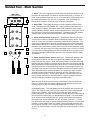


![Hire And Sales Catalogue V4.40 [april2013].](http://vs1.manualzilla.com/store/data/005975062_1-8950e43f7cbe305f577dc550ee5fbd1b-150x150.png)