1
Operating instructions
For the operator
Operating instructions
ecoTEC plus
Gas-fired wall-hung high efficiency boiler
GB
Table of contents
Table of contents
1
1.1
1.2
1.3
1.4
1.5
Notes on the documentation ................................ 3
Document storage ...................................................... 3
Symbols used ............................................................... 3
Applicability of the instructions .............................. 3
Identification plate ..................................................... 3
CE label ......................................................................... 3
2
2.1
2.1.1
2.1.2
2.2
2.3
Safety ............................................................................4
Safety and warning information .............................4
Classification of warnings .........................................4
Structure of warnings ................................................4
Intended Use ................................................................4
General safety instructions ......................................5
3
3.1
3.2
3.2.1
3.2.2
Equipment and functional description............... 7
Design ............................................................................ 7
Function of the boiler ................................................8
Heating mode ..............................................................8
Hot water production with DHW cylinder
(VU unit) ........................................................................8
Hot water production with VUW unit.....................8
3.2.3
4
4.1
4.2
4.3
4.3.1
4.3.2
4.3.3
4.3.4
4.4
4.4.1
4.4.2
4.5
4.5.1
4.5.2
4.5.3
4.6
4.6.1
4.7
4.8
4.8.1
4.8.2
4.8.3
4.9
4.9.1
4.9.2
2
Operation .....................................................................9
Overview of control elements .................................9
Display ......................................................................... 10
Preparing for start-up................................................11
Opening the isolator devices ...................................11
Switching on the boiler .............................................11
Checking the fill level of the heating system......12
Filling the heating system .......................................12
Setting the heating flow temperature ..................13
Setting the heating flow temperature
without a controller connected ..............................13
Setting the heating flow temperature
with a controller .........................................................14
Hot water production with VUW units..................14
Setting the hot water temperature .......................14
Activating/deactivating comfort mode ................14
Setting storage tank charging
(with actoSTOR) .........................................................16
Hot water production with VU units .....................17
Setting the hot water temperature .......................17
Setting a room thermostat or weather
compensator ...............................................................17
Switching the heating system off ..........................18
Switching hot water production off (VU unit) ....18
Switching heating mode off (summer mode) .....18
Temporarily taking the boiler out of service ......18
Protecting the heating system against frost ......19
Activating the frost protection function ..............19
Draining the heating system ...................................19
5
Energy saving tips ................................................. 20
6
6.1
6.2
6.3
6.4
6.5
Troubleshooting .......................................................22
Reading fault codes ..................................................23
Detecting and rectifying malfunctions ................23
Rectifying a water shortage...................................24
Resolving ignition faults..........................................24
Resolving faults in the air/exhaust
gas pipework .............................................................25
7
7.1
7.2
Maintenance..............................................................25
Maintaining the boiler..............................................25
Caring for your boiler ..............................................25
8
8.1
8.1.1
8.1.2
Decommissioning ....................................................26
Disconnecting the boiler permanently ................26
Disposing of the boiler ............................................26
Disposing of the packaging ....................................26
9
9.1
9.2
Manufacturer's guarantee and Vaillant
customer service ....................................................26
Vaillant Service..........................................................26
Factory guarantee ....................................................26
10
Technical data ..........................................................27
Glossary ....................................................................................32
Index .........................................................................................34
Operating instructions ecoTEC plus 0020124810_FT1b
Notes on the documentation 1
1
Notes on the documentation
The following instructions are intended to guide you
throughout the entire documentation. Other documents
apply in addition to these operating instructions.
We accept no liability for any damage caused by failure
to observe these instructions.
Other applicable documents
When operating the ecoTEC plus, you must observe all
operating instructions that are included with other
components of your system.
These operating instructions are included with the
individual components of the system.
1.1
Document storage
> Store these operating instructions and other
applicable documents in such a way that they are
available whenever required.
> If you move out or sell the appliance, pass on the
documents to the relevant person as well.
Unit
Type designation
Article number
ecoTEC plus
VU GB 126/5-5
0010011677
ecoTEC plus
VU GB 156/5-5
0010011678
ecoTEC plus
VU GB 186/5-5
0010011679
ecoTEC plus
VU GB 186/5-5 (LPG)
0010011680
ecoTEC plus
VU GB 246/5-5
0010011681
ecoTEC plus
VU GB 306/5-5
0010011682
ecoTEC plus
VU GB 306/5-5 (LPG)
0010011683
ecoTEC plus
VU GB 376/5-5
0010011684
ecoTEC plus
VUW GB 246/5-5
0010011685
ecoTEC plus
VUW GB 316/5-5
0010011686
ecoTEC plus
VUW GB 316/5-5 (LPG)
0010011687
ecoTEC plus
VUW GB 376/5-5
0010011688
ecoTEC plus
VUI GB 376/5-5
0010011691
Table 1.1 Type summary
To find out the article number of your boiler, refer to the
identification plate.
1.2
Symbols used
The symbols used in the text are explained below.
a
Symbol that denotes danger,
– Imminent danger to life
– Danger of severe personal injury
– Risk of minor personal injury
e
b
i
Symbol that denotes danger,
– Danger of death from electric shock
>
1.3
1.4
The identification plate of your Vaillant ecoTEC plus
boiler is attached at the factory to the bottom of your
boiler.
The seventh to sixteenth digits of the serial number on
the identification plate represent the article number.
1.5
Symbol that denotes danger,
– Risk of material damage
– Risk of damage to the environment
Identification plate
CE label
CE labelling shows that the units comply
with the basic requirements of the
applicable directives as stated on the
identification plate.
Symbol that denotes useful tips and
information
Symbol for a required action
Applicability of the instructions
These operating instructions apply exclusively to boilers
with the following article numbers:
Operating instructions ecoTEC plus 0020124810_FT1b
3
2 Safety
2
Safety
2.1
2.2
Safety and warning information
> When operating your boiler, take account of the
general safety instructions and the warning notes
that appear before each action.
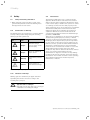
2.1.1
Classification of warnings
The warning notes are classified in accordance with the
severity of the possible danger using the following
warning signs and signal words:
Warning
signs
a
e
a
b
Signal
word
Explanation
Danger!
Immediate danger
to life or risk of severe
personal injury
Danger!
Danger of death from
electric shock
Warning!
Risk of minor personal
injury
Caution!
Risk of material or
environmental damage
Intended Use
The Vaillant ecoTEC plus boiler is a state-of-the-art
appliance which has been constructed in accordance
with recognised safety regulations. Nevertheless, there
is still a risk of injury or death to the operator or others
or of damage to the boiler and other property in the
event of improper use or use for which it is not intended.
The Vaillant ecoTEC plus boiler mentioned in these
instructions must only be installed and operated in
conjunction with the accessories mentioned in the
corresponding installation instructions Air/exhaust gas
pipework (¬ section 1.1).
This boiler is not intended for use by persons (including
children) having limited physical, sensory or mental
capacities or who have inadequate experience and/or
knowledge, unless supervised by a person responsible
for their safety or who has been given instructions by
them as to how to operate the boiler. Children must be
supervised to ensure that they do not play with the
boiler. The boiler is intended as a heater for closed hot
water/central heating systems and for hot water
production. Any other or additional use will be deemed
as not in accordance with intended use. The
manufacturer or supplier is not liable for any damage
resulting from such use. The user alone bears the risk.
Intended use also includes observance of the operating
and installation instructions and the inspection/
maintenance conditions.
Tab. 2.1 Meaning of danger signs and signal words
2.1.2
Structure of warnings
Warning signs are identified by an upper and lower
separating line and are laid out according to the
following basic principle:
a
4
Signal word!
Type and source of danger!
Explanation of the type and source of danger
> Measures for averting the danger
Operating instructions ecoTEC plus 0020124810_FT1b
Safety 2
2.3
General safety instructions
> Observe the following safety instructions at all times.
What to do in an emergency if you smell gas
Installation errors, damage, handling, unauthorised
installation sites or similar can cause gas to escape and
result in a risk of poisoning and explosion. If there is a
smell of gas in the building, proceed as follows:
> Avoid rooms that smell of gas.
> Open all accessible doors and windows fully and
ensure adequate ventilation.
> Avoid the use of naked flames (e.g. lighters, matches).
> Do not smoke.
> Do not use any electrical switches, mains plugs,
doorbells, telephones or other communication
systems in the building.
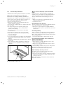
> Close the gas meter isolator device or the main
isolator device.
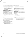
> If possible, close the gas stop cock on the boiler.
> Warn other occupants in the building by knocking
doors or calling out.
> Leave the building.
> If you can actually hear gas leaking, leave the building
immediately and ensure that others do not enter the
building.
> Alert the fire brigade and police when you are outside
the building.
> Use a telephone outside the building to inform the
emergency service department of the gas supply
company.
What to do in an emergency if you smell exhaust
fumes
Installation errors, damage, handling, unauthorised
installation sites or similar can cause exhaust fumes to
escape and result in a risk of poisoning. If there is a
smell of exhaust fumes in the building, proceed as
follows:
> Open all accessible doors and windows fully and
ensure adequate ventilation.
> Switch the boiler off.
Preventing the risk of explosion
The risk of explosion arises from the flammable mixture
of gas and air. Take note of the following:
> Do not use or store explosive or highly flammable
substances (such as petrol or paint) in the same room
as the boiler.
Preventing scalding
There is a danger of scalding at the hot water draw-off
points if the hot water temperatures are greater than
60 °C. Young children and elderly persons can be at risk
at lower temperatures.
> Select the temperature so that nobody is at risk.
Preventing material damage due to unauthorised
changes to the appliance.
Take note of the following:
> Never interfere or tamper with the boiler or other
parts of the heating system.
> Never try to carry out maintenance work or repairs
on the boiler yourself.
> Do not damage or remove any seals on components.
Only suitably qualified heating engineers or our
customer service may alter sealed components.
Material damage caused by corrosion
To prevent corrosion on the boiler and also on the
exhaust system, note the following:
> Do not use any sprays, solvents, chlorinated cleaning
agents, paint, adhesives or similar substances in the
vicinity of the boiler.
Under unfavourable circumstances, these substances
may cause corrosion.
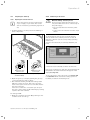
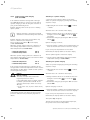
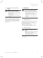
1
Fig. 2.1 Closing the gas stop cock
Operating instructions ecoTEC plus 0020124810_FT1b
5
2 Safety
Preventing frost damage
If there is a power cut, or if the room temperature is set
too low in individual rooms, it cannot be ruled out that
sections of the heating system might be damaged by
frost.
> If you are going to be away during a cold period,
make sure the heating system remains in operation
and that the rooms are sufficiently heated.
> Always observe the information on frost protection
provided in section 4.9.
Maintaining operation with an emergency power
generator in the event of a power cut
Your heating engineer connected your boiler to the
power mains during installation.
If the power supply is cut, it is possible that parts of the
heating system may become damaged by frost.
If you want to maintain the operation of the boiler
during a power cut using an emergency power
generator, take note of the following:
> Make sure that the technical values of this generator
(frequency, voltage, earthing) match those of the
power mains.
> Contact your heating engineer for advice.
What to do if there are leaks in the hot water pipes
Take note of the following:
> If there is a leak in the hot water pipes between the
boiler and draw-off points, immediately turn off the
cold water stop valve and have your heating engineer
repair the leak.
With Vaillant ecoTEC plus boilers, the cold water stop
valve is not included in the scope of supply of your
boiler.
> Ask your heating engineer where he had fitted the
cold water stop valve.
Preventing damage caused by low system pressure in
the heating system
To prevent the heating system being used when the
amount of water is too low and to therefore prevent any
subsequent damage that may be caused by this, note
the following:
> Check the filling pressure of the heating system at
regular intervals.
> Always observe the information on frost protection
provided in section 4.3.4.
Requirements for the installation site
Changes to the surroundings of the boiler
A malfunction can result in a risk of poisoning and
explosion.
> Never shut down the safety devices.
> Never tamper with the safety devices as this can
prevent them from operating correctly.
A ban on modifications also applies to alterations to
structural elements in the vicinity of the boiler which
might affect its operational safety.
> Always contact an approved heating engineer to make
modifications to the boiler or its surroundings.
Example: Enclosing the boiler in a cabinet requires that
you observe special design instructions.
> Never enclose your boiler yourself.
> If you want to enclose the boiler in this way, you
should ask your heating engineer.
6
i
It is not necessary to keep a clearance
between the boiler and combustible materials
or components, since at the nominal heat
output of your boiler the temperature on the
surface of the housing is always lower than
the maximum permissible temperature of
85 °C.
Operating instructions ecoTEC plus 0020124810_FT1b
Equipment and functional description 3
3
Equipment and functional
description
3.1
Design
16
14
1
1
2
2
3
15
13
4
4
5
5
6
7
14
3
6
12
7
8
8
9
9
13
11
12
10
11
Fig. 3.1
Functional components VUW
Key
1 Diaphragm expansion tank
2 Air intake pipe
3 Compact thermal module
4 Ignition electrode
5 Fan
6 Automatic air vent
7 Pressure gauge
8 High-efficiency pump
9 Priority switching valve with by-pass
10 Fan sensor (hot water)
11 Electronics box
12 Secondary heat exchanger
13 Gas fitting
14 Water pressure sensor
15 Integral condensation heat exchanger
16 Connection for the air/exhaust gas pipework
Operating instructions ecoTEC plus 0020124810_FT1b
10
Fig. 3.2 Functional components VU
Key
1 Diaphragm expansion tank
2 Air intake pipe
3 Compact thermal module
4 Ignition electrode
5 Fan
6 Automatic air vent
7 Pressure gauge
8 High-efficiency pump
9 Priority switching valve with by-pass
10 Electronics box
11 Gas fitting
12 Water pressure sensor
13 Integral condensation heat exchanger
14 Connection for the air/exhaust gas pipework
7
3 Equipment and functional description
3.2
Function of the boiler
Your Vaillant ecoTEC plus boiler is a high-efficiency, gasfired wall-hung boiler.
In addition to direct combustion heat, high-efficiency
gas-fired wall-hung boilers also use the heat of
condensation of the steam in the exhaust fumes. This
makes them more efficient than traditional boilers.
Furthermore, with condensing technology the exhaust
gas temperatures are much lower than with
conventional boilers, which reduces the heat lost via the
exhaust fumes. In addition, the lower system
temperatures of a heating system with high-efficiency
technology reduce the losses from conduction of heat
and radiation.
Your Vaillant ecoTEC plus boiler generates heat for
heating and/or hot water production.
VU units can be operated together with a domestic hot
water cylinder, which stores a larger volume of hot
water.
VUW units are fitted with built-in hot water production.
3.2.1
Heating mode
In heating mode the boiler heats the hot water and
pumps it through the radiators or underflooring heating
of your home (heating circuit). The hot water pumped
into the heating circuit exits the boiler at flow
temperature, emits its heat into the rooms and flows
back into the boiler once cooled to return temperature.
The heating water is then heated again.
3.2.2
then the boiler operates automatically and reheats the
domestic hot water cylinder. As soon as the water in the
domestic hot water cylinder has received the set
temperature, the boiler switches off. The heating pump
in your boiler continues to run for a short time in order
to supply the residual heat to the heating circuit.
3.2.3
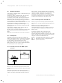
Hot water production with VUW unit
When you open a hot water tap (1) (sink, shower, bath,
etc.), the boiler operates automatically and supplies hot
water.
When you close the hot water tap. the boiler
automatically stops producing hot water.
The heating pump in your boiler continues to run for a
short time in order to supply the residual heat to the
heating circuit.
If you have activated comfort mode, the boiler
immediately supplies you with hot water at the
requested temperature without yo having to wait for the
water to heat up. For this, the hot water heat exchanger
is kept at a preselected temperature level.
i
To prevent unnecessary energy loss, set the
temperature selector not higher than the
required temperature.
Hot water production with DHW cylinder
(VU unit)
1
Fig. 3.3 Drawing off hot water
When you open a hot water tap (1) (sink, shower, bath,
etc.), the hot water is taken from the domestic hot water
cylinder.
Cold water than flows into the domestic hot water
cylinder in its place. If the hot water temperature in the
domestic hot water cylinder falls below the value set,
8
Operating instructions ecoTEC plus 0020124810_FT1b
Operation 4
4
Operation
4.1
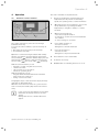
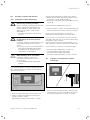
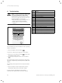
The control elements are explained below.
Overview of control elements
1
Display for showing the current heating flow
temperature, the fill pressure of the heating
system, the operating mode or other information
2
"Operating mode" selection button to choose and
call up information, e.g. heating and water
temperature; to navigate to "Next"; to confirm
set values
3
"Menu" selection button to
- select and call up information
- to navigate to a lower selection level within the
list of entries
- to cancel changes to set values
4
"Scroll down" arrow key to
- decrease set values
- Navigation to the next menu item
5
"Scroll up" arrow key to
- increase set value
- Navigation to the previous menu item
6
Reset button to clear certain faults
7
Controller (accessory)
8
On/Off button for switching the boiler on or off
1
2
3
8
4
5
6
7
Fig. 4.1 Control elements ecoTEC plus
The control elements for your boiler are arranged
behind the front flap.
To access the control elements, open the front flap as
follows:
> Reach into the recessed grip in the front flap.
> Fold down the front flap.
Operation is controlled using the buttons with softkey
function. For example, open the menu by pressing the
under the "Menu" display. You can
selection button
then navigate within the list of entries displayed using
the "Scroll up"
and "Scroll down"
arrow keys.
With the selection buttons you can
– navigate to a lower or higher selection level,
– confirm a set value,
– cancel a chance to a set value or
– activate an operating mode.
With the arrow keys you can
– navigate within the menu between the individual
points on the list of entries or
– change a selected set value.
A highlighted object is indicated in the display inversely
(light text on dark background).
When the end of the list of entries in a given selection
level is reached, the marker jumps back to the first list
entry.
i
If you do not press any buttons for more than
15 minutes, the display returns to the basic
display.
Changes that are not confirmed will not be
applied.
Operating instructions ecoTEC plus 0020124810_FT1b
9
4 Operation
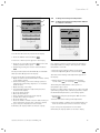
4.2
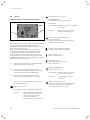
Display
Hot water production active
Digital Information and Analysis System (DIA)
On VUW/APC units:
flashing: Burner on in draw-off mode
9
10
11
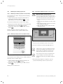
Fig. 4.2 Display ecoTEC plus
The ecoTEC plus boiler is fitted with a digital information
and analysis system (DIA). This system provides
information on the operating status of your boiler and
helps you deal with problems.
When your boiler is in normal mode the display (1)
shows the current heating flow temperature (in the
example 58 °C) and the current fill pressure of the
heating system in the bar graph display on the right.
If a fault develops, a fault code appears instead of the
temperature. The display of the ecoTEC plus also shows
additional information in plain text.
9
Display of the present heating flow temperature
of the heating system or fault code
10
Display of the current function of the right
selection button (in the basic display, the setting
of the heating and hot water temperature)
11
Display of the current function of the left
selection button (in the "Menu" basic display)
You can also see the following information from
the symbols displayed:
Heating mode active
On VU units:
permanently on: window activated for hot water
production
flashing:
Domestic hot water cylinder
is being heated, burner on
Display of the current fill pressure
(bar graph display).
The fill pressure must be in the mid range
between both dashed lines.
Display of the instantaneous burner
modulation rate (bar graph display)
Flame without cross:
Burner operation normal
Flame with cross:
Fault during burner operation;
Unit is switched off
Only on VUW/APC units:
Comfort mode active
permanently on: Comfort mode is activated
(activated by window)
flashing:
Comfort mode is active,
burner on
Burner blocking time active
This function is used to limit frequent on/off
operations, and therefore contributes to
prolonging the life of your boiler.
permanently on: Heat requirement, heating mode
flashing:
10
Burner on in heating mode (this
function is used to frequently
limit on/off operations and
therefore contributes to
increasing the life of your boiler)
Operating instructions ecoTEC plus 0020124810_FT1b
Operation 4
4.3
Preparing for start-up
4.3.2
4.3.1
Opening the isolator devices
b
i
The isolator devices are not included in the
scope of supply of your boiler. The isolator
devices are fitted by your heating engineer on
site.
> He must explain to you the position and handling of
these components.
Switching on the boiler
Caution!
Material damage caused by frost!
Frost protection and monitoring devices are
only active while the boiler is connected up to
the power supply.
> Do not isolate the boiler from the power
mains.
> Leave your boiler switched on at the on/off
switch.
To ensure that the frost protection and monitoring
devices remain active, switch your boiler on and off
using the controller (see the corresponding operating
instructions).
Section 8 describes how you can fully shutdown your
boiler.
2
3
1
1
2
4
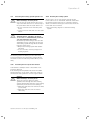
Fig. 4.4 Switching on the boiler
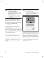
> Press the on/off switch (1) to switch on the boiler.
Maintenance taps
3 and 4 closed
Maintenance taps
3 and 4 open
Fig. 4.3 Open isolator devices (shown using the example
of service valves)
> Open the gas stop cock (1), by pushing the gas stop
cock in and turning it anti-clockwise.
> Check that the heating flow (3) and heating return
(4) service valves are open. This is the case if the
notch in the square on the service valve matches the
direction of the pipe.
If the service valves are closed, then you can open
the service valves using an SW 4 Allen key by rotating
a quarter turn anti-clockwise.
If the boiler is switched on, then the current heating flow
temperature and other information will appear in the
display (2) (Fig. 4.2).
To set your boiler to suit your needs, read section 4.4
to section 4.6 which describe the setting options for
hot water production and heating mode.
For unit type VUW:
> Open the cold water stop valve (2) by turning it anticlockwise as far as it will go.
Operating instructions ecoTEC plus 0020124810_FT1b
11
4 Operation
4.3.3
Checking the fill level of the heating system
b
Caution!
Low fill pressure can cause damage to the
unit!
Operating the heating system with low fill
pressure can cause damage to the boiler and
the heating system. The boiler switches off
automatically when the fill pressure falls
below 0.5 bar.
> Fill up the heating system as soon as the
fill pressure falls below 0.8 bar.
To avoid operating the system with insufficient water
and to prevent possible damage associated with this,
your boiler is fitted with a pressure sensor. This signals
the low pressure level if the level falls below 0.8 bar by
the water pressure value in the display flashing.
> Fill up the heating system as soon as the pressure
value in the display starts to flash.
i
If the fill pressure of the heating system falls
below 0.5 bar, then the boiler switches off and
the error message F.22 appears in the display.
The heating system must be topped up with
water before the boiler can be put into
operation again.
If the heating system extends over several storeys,
the system may require a higher filling pressure.
> Ask your heating engineer for details.
The filling pressure must lie between 1.0 and 2.0 bar
when the heating system is cold in order for the heating
system to operate properly. If the fill pressure falls below
this range, then you must top it up with water before
switching it on (¬ section 4.3.4).
> Check the fill pressure of the heating system during
start-up.
4.3.4
Filling the heating system
b
Caution!
Tap water that is extremely calciferous or
corrosive or contaminated by chemicals
can cause damage to the boiler!
Unsuitable tap water damages the seals and
diaphragms, blocks components in the boiler
and heating system through which the water
flows and causes noise.
> Only fill the heating system with suitable
tap water.
> In case of doubt, consult your heating
engineer.
The ecoTEC plus boiler has a digital pressure display.
You can see the fill pressure in the right bar graph
display or display the exact value using the selection
buttons to the right of the display.
The filling pressure must be between 1.0 and 2.0 bar
when the system is cold in order for the heating system
to operate properly (¬ see section 4.3.3).
> If the fill pressure is lower, then top it up with water.
> Press the on/off switch (¬ Fig. 4.1, 8) to switch on the
boiler (¬ section 4.3.2).
> Press the right "Operating mode" selection button
(heating/hot water).
If the heating system extends over several storeys, the
system may require a higher filling pressure.
> Ask your approved heating engineer about this.
The value of the flow temperature appears in the display.
The right selection button is now assigned the "Next"
function.
> Press the right selection button ("Next") until you
reach the water pressure display.
The value of the fill pressure appears in the display.
To exit the water pressure display and return to the
basic display:
> Press the "Next" or "Back" selection button until you
have reached the desired level or the basic display.
To fill up and to refill the heating system, you can
normally use tap water. In exceptional cases, however,
the water quality may not be suitable for filling the
heating system because the water is highly corrosive or
calciferous.
> If this is the case, contact your approved heating
engineer.
The heating system is filled via a filling cock provided by
the installer.
> Ask your heating engineer where the filling cock is
located.
> Ask your heating engineer to explain how to fill the
heating system.
If you do not press any buttons for more than
15 minutes, the display returns to the basic display.
12
Operating instructions ecoTEC plus 0020124810_FT1b
Operation 4
1
Water pressure
3
1,2bar
min. 0,5
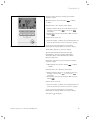
4.4
Setting the heating flow temperature
4.4.1
Setting the heating flow temperature without
a controller connected
2
max. 3,0
Target flow temp.
Back
58
°C
1/4
Cancel
Ok
Fig. 4.5 Display Fill pressure
You can show the exact fill pressure in the display.
> Press the "Menu" selection button
.
A selection of menu options appears in the display.
Fig. 4.6 Setting the heating flow temperature
> Press the "Scroll down" arrow key
as far as the
"Water pressure" menu option.
> Confirm by pressing the "Select" selection button
.
If no external controller is fitted, then set the heating
flow temperature according to the respective outside
temperature as follows:
The fill pressure (1) and the minimum (3) or maximum
water pressure (2) appear in the display.
Proceed as follows to fill the heating system:
> Open all radiator valves (thermostatic radiator valves)
of the heating system.
> Connect the filling cock for the heating system, as
explained by your heating engineer, to a cold water
draw-off valve.
> Open the filling cock slowly.
> Fill it with water until the required fill pressure is
reached in the display.
> Close the draw-off valve.
> Bleed all the radiators.
> Then check the fill pressure on the display.
> Fill with more water if required.
> Close the filling cock.
> Press the "Next" or "Back" selection button until you
have reached the desired level or the basic display.
If you do not press any buttons for more than
15 minutes, the display returns to the basic display.
> Press the on/off switch to switch on the boiler.
> Press the "Operating Mode" selection button
.
The value of the heating flow temperature appears in
the display.
> Change the heating flow temperature using the
"Scroll down"
or "Scroll up"
arrow keys.
The heating flow temperature is factory-set for
temperatures up to 75 °C.
If higher (or lower) values can be set on your boiler, then
your heating engineer has calibrated your unit to adjust
the maximum temperature to your heating system.
> Confirm the change by pressing the "OK" selection
.
button
You have now set the heating flow temperature.
> Press the "Next" or "Back" selection button until you
have reached the desired level or the basic display.
If you do not press any buttons for more than
15 minutes, the display returns to the basic display.
Operating instructions ecoTEC plus 0020124810_FT1b
13
4 Operation
4.4.2
Setting the heating flow temperature
with a controller
If your gas-fired wall-hung boiler has a room thermostat
control system or weather compensator, make the
following settings:
The flow temperature is automatically adjusted by the
controller (for information see the controller operating
instructions).
Hot water production with VUW units
4.5.1
Setting the hot water temperature
a
a
b
The hot water temperature is shown on the display.
> Change the hot water temperature with the "Scroll
down" (3) or "Scroll up" (4) arrow keys.
> Confirm the changes by pressing the "OK" selection
button (2).
The new hot water temperature is now set.
> Press the on/off switch to switch on the boiler.
> Set the maximum heating flow temperature
(¬ section 4.4.1).
4.5
> Press the on/off switch (1) to switch on the boiler.
> Set the hot water temperature by pressing the
following sequence of keys:
"Operating mode" selection button
--> "Next"
> Press the "Next" or "Back" selection button until you
have reached the desired level or the basic display.
If you do not press any buttons for more than
15 minutes, the display returns to the basic display.
Danger!
Risk of being scalded by hot water!
There is a danger of scalding at the hot water
draw-off points if the hot water temperatures
are greater than 60 °C. Young children and
the elderly can even be at danger at lower
temperatures.
> Select the temperature so that nobody
is at risk.
Danger!
Possible danger to life from legionella!
If the unit is used to reheat water in a solarbased drinking water heating system, note the
following:
> Set the minimum hot water temperature
to 60 °C.
Caution!
Material damage due to calcification.
If the water hardness is more than
-3.57 mol/m3 (20 °dH), there is a risk
of calcification.
> Set the maximum water temperature
to 50 °C.
If your controller is connected to the boiler via a twowire eBUS cable, then you can set the hot water target
temperature on the controller.
Ask your approved heating engineer whether or not
your controller is connected via a two-wire eBUS cable.
If your controller is connected via a two-wire eBUS:
> Set the hot water temperature on the boiler
to the maximum possible temperature.
> Set the desired hot water temperature
(hot water target temperature) on your controller.
4.5.2
Activating/deactivating comfort mode
Comfort mode immediately supplies you with hot water
at the required temperature, without you having to wait
for the water to heat up. To do this, the hot water heat
exchanger of the ecoTEC plus is kept at your selected
temperature level.
2
1
3
4
Fig. 4.7 Setting the hot water temperature
14
Operating instructions ecoTEC plus 0020124810_FT1b
Operation 4
Activate comfort mode by pressing the following
sequence of keys:
"Operating mode" selection button
--> "Next"
--> "Next"
"Comfort mode off" is shown on the display.
> Change "Comfort mode off" to "Comfort mode on"
using the "Scroll down"
or "Scroll up"
arrow keys.
> Confirm the change by pressing the "OK" selection
.
button
Comfort mode is now set.
> Press the "Next" or "Back" selection button until you
have reached the desired level or the basic display.
Fig. 4.8
Switching on/off the warm start function
If you do not press any buttons for more than
15 minutes, the display returns to the basic display.
The C symbol appears on the basic display.
The unit automatically matches the hot start
temperature to the set hot water temperature.
The heated water is then immediately available
when you draw it off.
Deactivate comfort mode by pressing the following
sequence of keys:
> "Operating mode" selection button
--> "Next"
--> "Next"
"Comfort mode on" is shown on the display.
> Change "Comfort mode on" to "Comfort mode off"
using the "Scroll down"
or "Scroll up"
arrow keys.
> Confirm the change by pressing the "OK" selection
.
button
Comfort mode is now off.
> Press the "Next" or "Back" selection button until you
have reached the desired level or the basic display.
If you do not press any buttons for more than
15 minutes, the display returns to the basic display.
The symbol " " disappears.
Operating instructions ecoTEC plus 0020124810_FT1b
15
4 Operation
4.5.3
Setting storage tank charging
(with actoSTOR)
Switching on cylinder charging
In an additional stratified storage tank of the type
actoSTOR VIH CL 20 S is connected you can switch
cylinder charging on and off using the controller on
your gas-fired wall-hung boiler.
Cylinder charging refers to the process for heating
up the cylinder.
> Press the on/off switch to switch on the boiler.
Switch on cylinder charging by pressing the following
sequence of keys:
> "Operating mode" selection button
--> "Next"
--> "Next"
"Comfort mode off" is shown on the display.
i
Cylinder charging is deactivated ex-works
and must be activated during initial start-up.
Cylinder charging of the layer storage tank is only
active if comfort mode is switched on.
This is shown by the symbol " " in the display
(¬ see section 4.5.2).
When the cylinder charging function is switched on,
the following temperatures can be set for the hot
water temperature (¬ section 4.5.1):
- minimum temperature
- maximum temperature
50 °C
65 °C
> Change "Comfort mode off" to "Comfort mode on"
using the "Scroll down"
or "Scroll up"
arrow keys.
> Confirm the change by pressing the "OK" selection
.
button
Cylinder charging is now set.
> Press the "Next" or "Back" selection button until you
have reached the desired level or the basic display.
If you do not press any buttons for more than
15 minutes, the display returns to the basic display.
The "C" symbol appears on the basic display.
When the cylinder charging function is switched off,
the following temperatures can be set for the hot water
temperature (¬ section 4.5.1):
- minimum temperature
- maximum temperature
35 °C
65 °C
If the cylinder charging function is switched off the
storage tank is not held at temperature. In this case the
unit switches on when water is drawn off and operates
on a through-flow principle.
a
Danger!
Risk of scalding!
The units are fitted with an automatic
legionella protection control:
If the temperature in the hot water domestic
hot water cylinder falls below 50 °C, the
cylinder is heated up to 70 °C once every
24 hours.
> If this is the case, try not to draw off any
water.
> Set the cylinder temperature using the hot water
temperature setting (¬ section 4.5.1).
Switching off cylinder charging
Switch off cylinder charging by pressing the following
sequence of keys:
> "Operating mode" selection button
--> "Next"
--> "Next"
"Comfort mode on" is shown on the display.
> Change "Comfort mode on" to "Comfort mode off"
using the "Scroll down"
or "Scroll up"
arrow keys.
> Confirm the change by pressing the "OK" selection
.
button
Cylinder charging is now off.
> Press the "Next" or "Back" selection button until you
have reached the desired level or the basic display.
Your heating engineer can switch off the legionella
protection function. Ask your heating engineer for
details.
If you do not press any buttons for more than
15 minutes, the display returns to the basic display.
The symbol " " disappears.
The unit now operates in the through-flow principle,
the cylinder is not held at temperature.
16
Operating instructions ecoTEC plus 0020124810_FT1b
Operation 4
4.6
Hot water production with VU units
4.6.1
Setting the hot water temperature
a
a
b
Danger!
Risk of being scalded by hot water!
There is a danger of scalding at the hot water
draw-off points if the temperatures are
greater than 60 °C. Young children and
elderly persons can be at risk at lower
temperatures.
> Select the temperature so that nobody
is at risk.
Danger!
Possible danger to life from legionella
formation.
In domestic hot water cylinders there is a risk
of legionella forming, which can causes
illness.
> If the unit is used for post-heating within a
solar-supported drinking water heating
installation, set the hot water outlet
temperature to at least 60 °C.
Caution!
Material damage due to calcification.
If the water hardness is more than
-3.57 mol/m3 (20 °dH), there is a risk
of calcification.
> Set the maximum water temperature
to 50 °C.
The hot water temperature is shown on the display.
> Change the hot water temperature with the "Scroll
down" (3) or "Scroll up" (4) arrow keys.
> Confirm the changes by pressing the "OK" selection
button (2).
The new hot water temperature is now set.
> Press the "Next" or "Back" selection button until you
have reached the desired level or the basic display.
If you do not press any buttons for more than
15 minutes, the display returns to the basic display.
If your controller is connected to the boiler via a twowire eBUS cable, then you can set the hot water target
temperature on the controller.
Ask your approved heating engineer whether or not
your controller is connected via a two-wire eBUS cable.
If your controller is connected via a two-wire eBUS
> Set the hot water temperature on the boiler
to the maximum possible temperature.
> Set the desired hot water temperature
(hot water target temperature) on your controller.
4.7
Setting a room thermostat or weather
compensator
1
To produce hot water in conjunction with the VU unit
type a VIH-type domestic hot water cylinder must be
connected to the boiler.
2
1
3
4
Fig. 4.9 Setting the hot water temperature
> Press the on/off switch (1) to switch on the boiler.
> Set the hot water temperature by pressing the
following sequence of keys:
"Operating mode" (2) selection button --> "Next"
Operating instructions ecoTEC plus 0020124810_FT1b
2
Fig. 4.10 Setting a room thermostat or weather compensator
> Set the room thermostat, weather compensator (1)
and thermostatic radiator valves (2) as specified in
the operating instructions for these accessories.
17
4 Operation
4.8
Switching the heating system off
4.8.3 Temporarily taking the boiler out of service
4.8.1
Switching hot water production off (VU unit)
b
You can switch off cylinder charging without switching
off heating mode.
> Set the lowest possible hot water temperature by
pressing the following sequence of keys:
"Operating mode" selection button
--> "Next"
The hot water temperature is shown on the display.
> Change the hot water temperature to the lowest value
30 °C with the "Scroll down"
arrow key.
> Confirm the change by pressing the "OK" selection
button
.
Cylinder charging is switched off. Only the frost
protection function for the cylinder remains active.
Caution!
Material damage caused by frost!
Frost protection and monitoring devices are
only active while the boiler is connected up to
the power mains and the on/off switch is on.
> Do not isolate the boiler from the power
mains.
> Leave your boiler switched on at the on/off
switch.
> Only switch the boiler on and off in normal
mode using the controller.
> Make sure that the boiler cannot become
damaged by frost.
2
1
4.8.2 Switching heating mode off (summer mode)
Target flow temp.
Heating off
1/4
Cancel
Ok
Fig. 4.12 Switching off the boiler
> Press the on/off switch (1) to switch off the boiler.
If the boiler is switched off, the display (2) turns off.
Fig. 4.11 Switching off heating mode (summer operation)
You can switch off the heating mode in summer without
switching off the hot water supply.
> Set the heating flow temperature to "Heating off"
with the "Scroll down"
arrow key.
> Confirm the change by pressing the "OK" selection
button
.
i
If the boiler is going to be unused for longer
periods (e.g. holiday), you should also close
the gas stop cock and the cold water stop
valve, but only if there is no risk of frost.
i
The isolator devices are not included in the
scope of supply of your boiler. These are
installed are fitted by your heating engineer
on site.
> Ask your heating engineer to explain to you the
position and handling of these isolator devices.
Heating mode is switched off.
18
Operating instructions ecoTEC plus 0020124810_FT1b
Operation 4
4.9
Protecting the heating system against frost
b
Caution!
Material damage caused by frost!
Frost protection and monitoring devices are
only active while the boiler is connected up to
the power mains and the on/off switch is on.
> Do not isolate the boiler from the power
mains.
> Leave your boiler switched on at the on/off
switch.
b
Caution!
Tap water that is extremely calciferous
or corrosive or contaminated by chemicals
can cause damage to the boiler!
Unsuitable tap water damages the seals and
diaphragms, blocks components in the boiler
and heating system through which the water
flows and causes noise.
> Only fill the heating system with suitable
tap water.
> In case of doubt, consult your approved
heating engineer.
4.9.2
Draining the heating system
Another way to protect the heating system and the
boiler from frost is to drain them. You must ensure that
the heating system and boiler are completely drained.
All the cold and hot water pipes in the house and in the
boiler must also be drained.
> Ask your heating engineer to drain the heating
system.
The heating system and water pipes are sufficiently
protected against frost if the heating system remains
on and the rooms are sufficiently heated while you are
away.
4.9.1
Activating the frost protection function
Your Vaillant ecoTEC plus boiler is fitted with a frost
protection function:
If the heating flow temperature falls below 5 °C when
the main switch is on, the boiler comes into operation
and heats the heat generation circuit to approx. 30 °C.
b
Caution!
Material damage caused by frost!
The frost protection function cannot
guarantee flow through the entire heating
system, which means that parts of the heating
system may freeze and become damaged.
> Make sure that the boiler remains on whilst
you are away.
> Make sure that the rooms are heated
sufficiently.
Operating instructions ecoTEC plus 0020124810_FT1b
19
5 Energy saving tips
5
Energy saving tips
Installation of a weather compensator
Weather compensators regulate the heating flow
temperature with reference to the outside temperature.
No more heat is generated than is currently required.
The designated heating flow temperature for the
corresponding outside temperature must be set on the
weather compensator. This setting must not be greater
than that required by the design of the heating system.
The correct setting is normally undertaken by the
heating engineer. The required heating and setback
phases (e.g. at night) are automatically switched on/off
using integrated timer programmes. Weather
compensators combined with thermostatic radiator
valves are the most economical form of heating
regulation.
Energy-saving mode of the heating system
Reduce the room temperature at night and in your
absence. This is most easily and reliably achieved using
controllers with timer programmes that can be selected
according to individual requirements. At such times, set
the room temperature approx. 5 °C lower than during
full heating times. Reduction of more than 5 °C brings
no additional energy saving, because then increased
heating capacities would be needed for the next full
heating period. Only for longer absences, e.g. holidays,
is it worthwhile to further lower the temperatures.
However, in winter, make sure that there is adequate
frost protection.
Room temperature
Set the room temperature only as high as would be
enough for your comfort level. Each extra degree would
mean an increased energy consumption of about 6%.
Adjust the room temperature according to the use of the
specific room. For example, normally, bedrooms or
seldom used rooms are heated to 20 °C.
Setting the operating mode
In warmer seasons, when the apartment needs no
heating, turn the heating to summer mode. The heating
mode is then shut off; however, the boiler or the heating
system remains ready for operation for hot water
production.
Uniform heating
Often, in an apartment with central heating, only one
room is heated. Adjacent rooms are also heated without
regulation by the enclosing surfaces of the room, i.e.
walls, doors, windows, roofs and floors, which means
that an unwanted loss of thermal energy occurs. In these
kind of operating conditions the power of the radiator in
this heated room is obviously insufficient. Consequently,
the room cannot be heated adequately and an
uncomfortable feeling of coolness prevails (the same
effect is produced when doors between heated and
unheated or partially heated rooms remain open).
20
This is false economy: The heating is in operation and
still the room temperature is not comfortably warm.
Greater heating comfort and a more practical operating
mode is achieved when all rooms in an apartment are
heated uniformly and in accordance to their usage. The
building structure can also suffer if components of the
building are unheated or only inadequately heated.
Thermostatic radiator valves and room thermostats
Nowadays, all radiators should be fitted with
thermostatic radiator valves as a matter of course. They
maintain the set room temperature precisely. You can
adjust the room temperature to suit your individual
requirements and ensure effective operation of your
heating system using thermostatic radiator valves in
combination with a room thermostat (or weather
compensator). In the room where the room thermostat
is located, all the radiator valves should be fully opened,
as otherwise the two regulating systems will work
against each other and the regulation quality can be
affected. And besides, the following user behaviour can
frequently be observed: As soon as the room becomes
too hot the operator turns the thermostatic radiator
valve off (or specifies a lower temperature at the room
thermostat). If after a period of time the user feels cold
and opens the thermostatic radiator valve again. This
procedure is not only inconvenient, it is also completely
unnecessary as a correctly functioning thermostatic
valve does this automatically: If the room temperature
rises above the value set on the sensor head, the
thermostatic radiator valve shuts off automatically,
when the temperature drops below the defined value,
it opens again.
Do not cover controllers
Do not cover your controllers with furniture, drapes or
similar objects. The room air must circulate unhindered.
Covered thermostatic radiator valves can be equipped
with remote sensors and thus still work.
Ventilating residential spaces
During the heating period, open windows only for
ventilation and not for temperature regulation. A brief,
forced change of air is more effective and energy-saving
than windows that are kept open for a long time. We
recommend that the windows be opened fully for a short
period. During ventilation, close all thermostatic radiator
valves in the room or set the room thermostat to
minimum temperature. These measures guarantee a
sufficient exchange of air and avoid unnecessary cooling
and loss of energy (e.g. due to unwanted activation of
the heating system during ventilation).
Appropriate hot water temperature
Anyone wanting to wash their hands under warm water
does not want to have their fingers scalded. The
following applies both for boilers with integral hot water
production and for boilers with hot water cylinders
connected: The warm water should only be heated up to
Operating instructions ecoTEC plus 0020124810_FT1b
Energy saving tips 5
the extent that is necessary for use. Any further heating
results in unnecessary power consumption and hot
water temperatures of more than 60 °C also lead to
increased lime scale reduction.
Switching on comfort mode (only VUW):
Comfort mode immediately supplies you with hot water
at the required temperature, without you having to wait
for the water to heat up. For this, the hot water heat
exchanger is kept at a preselected temperature level. To
prevent energy loss, set the temperature selector not
higher than the required temperature. If you do not need
hot water for a long period, it is recommended to turn
off comfort mode to save energy further.
Energy-conscious use of water
Energy-conscious use of water can also reduce costs
considerably, e.g. taking showers instead of baths:
whereas about 150 litres of water are required for a
bath, a modern shower equipped with water saving
fittings only requires a third of this water quantity. By
the way: a dripping water tap wastes up to 2,000 litres
of water and a leaking toilet flush up to 4,000 litres of
water each year. On the other hand, a new seal only
costs a few cents.
Operating instructions ecoTEC plus 0020124810_FT1b
Run circulation pumps only if needed
Circulation pumps facilitate the continuous circulation of
hot water through the piping system which means that
hot water is immediately available, also at more distant
draw-off points. These pumps undoubtedly enhance the
convenience of the hot water production process. But
they also need power. And circulating hot water that is
not used cools off when passing through pipes and then
needs to be reheated. Therefore, circulation pumps are
to be operated only when hot water is actually needed
for the household. Individual timer programmes can be
defined using switching clocks, which are already
installed or can be retrofitted in most circulation pumps.
Weather compensators often have ancillary functions for
controlling circulation pump timings. Consult your
heating engineer. Another option is to turn on the
circulation only for concrete needs for a specific period
of time by using a button or switch installed near a
frequently used draw-off point. A corresponding button
can be connected to the Vaillant ecoTEC plus boiler
electronics.
21
6 Troubleshooting
6
Troubleshooting
a
Display
Danger!
Danger of injury and material damage due
to incorrect maintenance and repairs!
If maintenance is not carried out, or carried
out incorrectly, this may adversely affect the
operating reliability of your boiler.
> Never attempt to perform maintenance or
repairs on your boiler by yourself.
> Always employ an approved heating
engineer.
Meaning
Displays in heating mode
S 00
Heating no heat demand
S 02
Heating mode pump pre-run
S 03
Heating mode ignition
S 04
Heating mode burner on
S 06
Heating mode fan overrun
S 07
Heating mode pump overrun
S 08
Heating, remaining cut-off time xx min
S 31
No heat demand, summer operating mode
S 34
Heating mode, frost protection
S 10
Hot water demand via fan sensor
S 14
Hot water handling mode burner on
S 20
Hot water demand
S 22
Hot water handling mode pump pre-run
Displays in hot water handling mode (VUW unit)
1
Status
S 00
Displays in storage tank charging
2
Heating
no heat requirement
Tab. 6.1 Status codes and what they mean (selection)
Back
Fig. 6.1 Live Monitor
The Live Monitor provides information on the operating
status of your boiler.
> Press the "Menu" selection button
.
A selection of menu options appears in the display.
> Press the "Scroll down" arrow key
as far as the
"Live Monitor" menu option.
> Confirm by pressing the "Select" selection button
.
The current status of the boiler appears in the display
(1), which is explained by additional plain text (2) in the
display.
The following table explains the most important status
codes.
> Press the "Back" selection button until you have
reached the desired level or the basic display.
If you do not press any buttons for more than
15 minutes, the display returns to the basic display.
22
Operating instructions ecoTEC plus 0020124810_FT1b
Troubleshooting 6
6.1
Reading fault codes
If a fault develops in the boiler, the display shows a fault
code starting with "F...".
A plain text display explains the displayed fault code.
Example for F.10: "Short circuit heating feed sensor".
Fault codes have priority over all other displays. If a fault
occurs, then the display no longer shows the current
heating flow temperature.
If multiple faults occur at the same time, then the
display shows the corresponding fault codes for two
seconds each in sequence.
> If your boiler displays a fault code, then contact your
heating engineer.
6.2
Detecting and rectifying malfunctions
If problems occur whilst operating your boiler,
you can carry out the following self-checks:
Problem
No hot water,
heating stays cold;
Boiler does not start
Hot water handling, no
problem;
Heating does not start:
Possible cause
Solution
Building gas stop cock closed
Open building gas stop cock
(¬ section 4.3.1)
Building power supply switched off
Switch on building power supply
Mains switch on boiler switched off
Switch on mains switch on boiler
(¬ section 4.3.2)
The heating flow temperature is set too low or in the
"Heating off" position (¬ section 4.8.2) and/or the
hot water temperature is too low
Set the heating flow temperature to the
desired temperature (¬ section 4.4) and/or
set the hot water temperature to the desired
temperature (¬ section 4.5 and 4.6)
Fill pressure of the heating system too low
Top up the heating system with water
(¬ section. 4.3.4)
Air in the heating system
Bleed the radiators;
If the problem occurs again:
Contact your heating engineer
Ignition malfunction
Press the reset button;
If the problem occurs again:
Contact your heating engineer
(¬ section 6.4)
No heating demand via the controller
Check the timer programme on the controller
and correct if necessary;
Check the room temperature and correct the
target room temperature if necessary
(¬ section 4.7; Controller operating
instructions)
Tab. 6.2 Detecting and rectifying malfunctions
> If after checking the points mentioned in Tab. 6.2
your boiler still shows signs of a fault, contact your
heating engineer to troubleshoot the problem.
Operating instructions ecoTEC plus 0020124810_FT1b
23
Troubleshooting 6
6.3
Rectifying a water shortage
b
Caution!
Tap water that is extremely calciferous or
corrosive or contaminated by chemicals
can cause material damage!
Unsuitable tap water damages the seals and
diaphragms, blocks components in the boiler
and heating system through which the water
flows and causes noise.
> Only fill the heating system with suitable
tap water.
> In case of doubt, consult your approved
heating engineer.
6.4
Resolving ignition faults
b
Caution!
Risk of damage due to improper alterations!
Improper alterations or persistent faults can
result in material damage.
> If you are unable to resolve the ignition
problem yourself by resetting the boiler
three times, then consult your heating
engineer.
1
F.28
As soon as the fill pressure falls below a limit, the
service message "Check water pressure" appears in the
display.
The filling pressure must be between 1.0 bar and 2.0 bar
when the system is cold in order for the heating system
to operate properly (¬ see section 4.3.3).
> If the fill pressure is lower, then top it up with water
(¬ section 4.3.4).
As soon as the system has been topped up with
sufficient water, the message disappears automatically
after approx. 20 seconds.
If the system falls below a pressure of 0.5 bar, the boiler
will switch off. The error message "F.22" appears in the
display. The system must be topped up with water before
the unit can be put into operation again. If the pressure
drops frequently the reason for the loss of hot water
must be identified and eliminated
> Contact your heating engineer.
If the heating system extends over several storeys, the
system may require a higher filling pressure.
> Ask your approved heating engineer about this.
To fill up and to refill the heating system, you can
normally use tap water. In exceptional cases, however,
the water quality may not be suitable for filling the
heating system because the water is highly corrosive or
calciferous.
> If this is the case, contact your approved heating
engineer.
24
Failure in start up
Igntn unsuccessful
2
Menu
3
Fig. 6.2 Troubleshooting
If the burner fails to ignite after five attempts, the boiler
will not operate and switches to "Fault". This is indicated
by the fault code "F.28” or "F.29” (1) on the display.
On Vaillant ecoTEC plus boilers, a struck through flame
symbol is also displayed along with the relevant plain
text in the display, e. g. for F.28: "Failure during starting,
ignition unsuccessful" (2).
The boiler will only ignite automatically again once you
have reset it manually.
> To reset the boiler manually, press the reset button
(3) and hold for one second.
Operating instructions ecoTEC plus 0020124810_FT1b
Troubleshooting 6
Maintenance 7
6.5
Resolving faults in the air/exhaust gas
pipework
a
Danger!
Risk of injury and material damage
resulting from improper modifications!
Improper alterations can affect the operating
safety of your boiler.
> Never attempt to perform repairs on your
boiler by yourself.
> Always employ a recognised heating
engineer.
The boilers are fitted with a blower. If the blower
does not work properly, the boiler will switch itself
off. The error message "F.32" appears in the display.
The displayed fault code is additionally explained by
a corresponding plain text message in the display:
"Blower fault".
7
Maintenance
a
7.1
Danger!
Danger of injury and material damage due
to incorrect maintenance and repairs!
If maintenance is not carried out, or carried
out incorrectly, this may adversely affect the
operating reliability of your boiler.
> Never attempt to perform maintenance
work or repairs on your water boiler by
yourself.
> Always employ a recognised heating
engineer.
Maintaining the boiler
Permanent operational readiness and safety, reliability
and a long working life require inspections and
maintenance work to be carried out annually on the
boiler by a heating engineer.
Regular servicing ensures maximum efficiency and
economical operation of your boiler.
We recommend making a maintenance agreement.
7.2
Caring for your boiler
b
Caution!
Unsuitable cleaning agents can cause
damage!
Unsuitable cleaning agents (scouring or other
cleaning agents) can damage the exterior, the
fittings or the control elements.
> Do not use sprays, solvents or cleaning
agents containing chlorine.
> Clean the exterior of your boiler with a damp cloth
and a little soap.
Operating instructions ecoTEC plus 0020124810_FT1b
25
8 Decommissioning
9 Manufacturer's guarantee and Vaillant customer service
8
8.1
Decommissioning
Disconnecting the boiler permanently
> Contact a heating engineer to disconnect the boiler
permanently.
8.1.1
Disposing of the boiler
Do not dispose of your Vaillant ecoTEC plus boiler or any
of its accessories in the household waste.
> Make sure the old unit and any accessories are
disposed of properly.
> Observe national regulations.
8.1.2
9
Disposing of the packaging
Arrange for the approved heating engineer who installed
the boiler to dispose of the transport packaging.
9.1
Manufacturer's guarantee and
Vaillant customer service
Vaillant Service
To ensure regular servicing, it is strongly recommended
that arrangements are made for a Maintenance
Agreement. Please contact Vaillant Service Solutions
(0870 6060 777) for further details.
9.2
Factory guarantee
Two year guarantee for ecoTEC plus appliances
Vaillant undertakes to rectify any manufacturing defect
that occurs within twenty-four months of the installation
date.
For the 2nd year of the guarantee to be valid an annual
service must be carried out by a competent person
approved at the time by the Health and Safety Executive
one year after installation.
The cost of this annual service is not included in the
guarantee.
Registering with us
Registration is simple. Just complete the Guarantee
Registration Card and return to Vaillant within 30 days
of installation. Your details will then be automatically
registered within the Vaillant scheme.
Note: No receipt will be issued.
Immediate help
If your Vaillant boiler develops a fault your first action
should be to contact your installer, as his professional
assessment is needed under the terms of our Guarantee.
If you are unable to contact your installer, phone Vaillant
0870 6060 777
26
Operating instructions ecoTEC plus 0020124810_FT1b
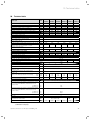
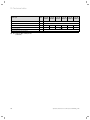
10 Technical data
10 Technical data
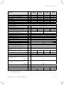
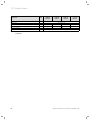
ecoTEC plus
Nominal heat output range P at 40/30 °C
Nominal heat output range P at 50/30 °C
Nominal heat output range P at 60/40 °C
Nominal heat output range P at 80/60 °C
Hot water output
Maximum thermal load for heating drinking water
Maximum thermal load on heating-side
Minimum thermal load
Heating output setting range
Heating
max. flow temperature
Setting range max. flow temperature
(factory setting: 75 °C)
permissible total over-pressure
Circulation water volume (with reference to T = 20 K)
Condensate volume approx. (pH value 3.5- 4.0)
in heating mode 50 °C supply/30 °C return
Residual feed head pump
(at nominal circulation water volume)
Electrical power consumption at 30% part load
Hot water handling (only VUW)
Least water volume
Water volume (at T = 35 K)
Water volume (at T = 30 K)
Permitted overpressure
Required connection pressure
Hot water discharge temperature range
General
Unit gas connection
Unit heating connection
Unit cold and hot water connection
Exhaust gas connecting pieces
Gas connection pressure (gas flow pressure)
natural gas, G20
Gas connection pressure (gas flow pressure)
propane, G31
Connection value at 15 °C and 1013 mbar
(based on hot water production if necessary)
G20
G31
Exhaust gas mass flow min./max.
Flue gas temperature min./max.
Exhaust gas connection approval
Standard utilisation rate based on nominal heat output
(in accordance with DIN 4702, Part 8) based on Hi
(heating value)
at 75/60 °C
at 40/30 °C
Standard utilisation rate based on nominal heat output
(in accordance with DIN 4702, Part 8) based on Hs
(calorific value)
at 75/60 °C
at 40/30 °C
30% efficiency
Unit
VU GB
126/5-5
VU GB
156/5-5
VU GB
186/5-5
VU GB
246/5-5
VU GB
306/5-5
VU GB
376/5-5
kW
kW
kW
kW
kW
kW
kW
kW
kW
3.3 - 13.1
3.2 - 12.9
3.1 - 12.5
3.0 - 12.0
12.0
12.4
12.4
3.1
3 - 12
3.3 - 16.4
3.2 - 16.1
3.1 - 15.7
3.0 - 15.0
15.0
15.5
15.5
3.1
3 - 15
4.1 - 19.7
4.1 - 19.3
3.9 - 18.8
3.8 - 18.0
18.0
18.6
18.6
3.9
4 - 18
5.7 - 26.2
5.6 - 25.7
5.5 - 24.9
5.2 - 24.0
24.0
24.7
24.7
5.4
5 - 24
6.4 - 32.8
6.2 - 32.1
6.1 - 31.2
5.8 - 30.0
30.0
30.9
30.9
6.0
6 - 30
7.0 - 40.4
6.9 - 39.6
6.7 - 38.5
6.4 - 37.0
37.0
38.1
38.1
6.6
6 - 37
°C
85
°C
30 - 80
bar
l/min
516
645
774
3.0
1032
1290
1591
l/h
1.2
1.6
1.9
2.5
3.1
3.8
mbar
W
l/min
l/min
l/min
bar
bar
°C
250
200
40
40
45
4.9
5.7
6.1
7.2
7.4
8.6
Installation weight approx.
50
50
9.8
11.5
12.3
14.3
15.2
17.7
1.5
10.0
0.35
35 - 65
Inches
Inches
Inches
G 1/2
G 3/4
G 3/4
mm
60/100 (concentric), optional 80/125 (concentric)
mbar
20
mbar
37
m3/h
kg/h
g/s
°C
1.3
0.96
1.4/5.6
1.6
1.2
1.4/7.0
2.0
2.6
3.3
1.44
1.92
2.4
1.8/8.4
2.4/11.1
2.7/13.9
40/70
C13. C33, C43, C53, C63, C83, C93, B53
%
%
107
109
%
%
%
96.4
98.2
108
NOx class
Unit dimensions (H x W x D)
50
4.0
2.96
3.0/17.1
5
mm
kg
720 x 440 720 x 440
x 369
x 403
720 x 440 x 335
35
35
35
37
39
41
Tab. 16.1 Technical data ecoTEC plus VU
(continued on next page)
Operating instructions ecoTEC plus 0020124810_FT1b
27
10 Technical data
ecoTEC plus
Unit
Electric connection
V/Hz
VU GB
126/5-5
VU GB
156/5-5
VU GB
186/5-5
VU GB
246/5-5
VU GB
306/5-5
VU GB
376/5-5
230/50
Built-in fuse
2 A, slow-blow
Minimum electrical power consumption
W
40
40
45
50
50
50
Maximum electrical power consumption
W
90
90
90
95
95
110
type of protection
IP X4 D
Quality mark/certification number
Tab. 16.1 Technical data ecoTEC plus VU
(continued)
28
Operating instructions ecoTEC plus 0020124810_FT1b
Technical data 10
ecoTEC plus
Nominal heat output range P at 40/30 °C
Nominal heat output range P at 50/30 °C
Nominal heat output range P at 60/40 °C
Nominal heat output range P at 80/60 °C
Hot water output
Maximum thermal load for heating drinking water
Maximum thermal load on heating-side
Minimum thermal load
Heating output setting range
Heating
max. flow temperature
Setting range max. flow temperature
(factory setting: 75 °C)
permissible total over-pressure
Circulation water volume (with reference to T = 20 K)
Condensate volume approx. (pH value 3.5- 4.0)
in heating mode 50 °C supply/30 °C return
Residual feed head pump
(at nominal circulation water volume)
Electrical power consumption at 30% part load
Hot water handling (only VUW)
Least water volume
Water volume (at T = 35 K)
Water volume (at T = 30 K)
Permitted overpressure
Required connection pressure
Hot water discharge temperature range
General
Unit gas connection
Unit heating connection
Unit cold and hot water connection
Exhaust gas connecting pieces
Gas connection pressure (gas flow pressure)
natural gas, G20
Gas connection pressure (gas flow pressure)
propane, G31
Connection value at 15 °C and 1013 mbar
(based on hot water production if necessary)
G20
G31
Exhaust gas mass flow min./max.
Flue gas temperature min./max.
Exhaust gas connection approval
Standard utilisation rate based on nominal heat output
(in accordance with DIN 4702, Part 8) based on Hi
(heating value)
at 75/60 °C
at 40/30 °C
Standard utilisation rate based on nominal heat output
(in accordance with DIN 4702, Part 8) based on Hs
(calorific value)
at 75/60 °C
at 40/30 °C
30% efficiency
Unit
VUW GB
246/5-5
VUW GB
316/5-5
VUW GB
376/5-5
VUI GB
376/5-5
kW
kW
kW
kW
kW
kW
kW
kW
kW
4.1 - 20.8
4.1 - 20.4
3.9 - 19.8
3.8 - 19.0
24.0
24.7
19.6
3.9
4 - 19
5.7 - 26.2
5.6 - 25.7
5.5 - 24.9
5.2 - 24.0
30.3
31.2
24.7
5.4
5 - 24
7.0 - 30.6
6.9 - 30.1
6.7 - 29.2
6.4 - 28.0
38.0
39.2
28.9
6.6
6 - 28
7.0 - 30.6
6.9 - 30.1
6.7 - 29.2
6.4 - 28.0
38.0
39.2
28.9
6.6
6 - 28
°C
85
°C
30 - 80
bar
l/min
817
1032
3.0
1204
1204
l/h
2.0
2.5
2.9
2.9
mbar
W
l/min
l/min
l/min
bar
bar
°C
250
200
45
50
9.8
11.5
12.4
14.5
Installation weight approx.
50
15.6
18.2
15.6
18.2
1.5
10.0
0.35
35 - 65
Inches
Inches
Inches
G 1/2
G 3/4
G 3/4
mm
60/100 (concentric), optional 80/125 (concentric)
mbar
20
mbar
37
m3/h
kg/h
g/s
°C
2.6
1.924
1.8/11.1
3.3
2.42
2.4/14.0
4.1
3.05
3.0/17.6
4.1
3.05
3.0/17.6
40/70
C13, C33, C43, C53, C63, C83, C93, B53
%
%
107
109
%
%
%
96.4
98.2
108
NOx class
Unit dimensions (H x W x D)
50
5
mm
kg
720 x 440 x 335
36
38
720 x 440 x 369 720 x 440 x 403
41
43
Tab. 16.2 Technical data ecoTEC plus VUW/VUI
(continued on next page)
Operating instructions ecoTEC plus 0020124810_FT1b
29
10 Technical data
ecoTEC plus
Unit
Electric connection
V/Hz
VUW GB
246/5-5
VUW GB
316/5-5
VUW GB
376/5-5
VUI GB
376/5-5
230/50
Built-in fuse
2 A, slow-blow
Minimum electrical power consumption
W
45
50
50
50
Maximum electrical power consumption
W
90
95
110
110
type of protection
IP X4 D
Quality mark/certification number
Tab. 16.2 Technical data ecoTEC plus VUW/VUI
(continued)
30
Operating instructions ecoTEC plus 0020124810_FT1b
Operating instructions ecoTEC plus 0020124810_FT1b
31
Glossary
Glossary
Air/exhaust gas pipework
The air/exhaust gas pipework consists of all components
that route combustion air to the boiler or exhaust gas
from the boiler.
Burner
The burner on a condensing boiler is the component in
which the gas/air mix is control-burnt.
Calorific value
Unlike the heating value, the calorific value of a fuel
describes the total useable heat during combustion,
based on the quantity of fuel used, including the
condensation heat in the steam. Condensing boilers use
this additional condensation heat to achieve much high
efficiency levels than conventional boilers.
Controller
The controller is the interface to the boiler and can be
used to adjust the room temperature, hot water
temperature, heating times or night-time temperature
reduction.
A distinction is made between room thermostat, weather
compensator and solar controller.
Cylinder charging
Cylinder charging refers to the process for heating up
the cylinder.
See also hot water production.
Dew point
The dew point is the temperature at which steam turns
to liquid (condensation). The steam in the exhaust fumes
from the boiler contains thermal energy, which can be
released by condensation. In gas-fired and oil-fired
boilers using calorific values, the exhaust gases are
cooled so that the steam condenses and the heat that it
contains can be output into the heating system.
32
eBUS
The abbreviation eBUS is short for energyBUS.
The eBUS is a special cable system used in the heating
technology field, which is used for communication
between the heating technology components (e.g.
controller, boiler, vrnetDIALOG).
Frost protection
The frost protection function protects your heating
system and apartment from frost damage. If the heating
flow temperature falls below 5 °C when the main switch
is on, the boiler comes into operation and heats the heat
generation circuit to approx. 30 °C.
Heating flow temperature
Your boiler heats water which is pumped through your
heating system. The temperature of this hot water as it
leaves the boiler is referred to as the heating flow
temperature.
Hot water production VU units
Your boiler heats the water in the domestic hot water
cylinder to the selected target temperature. If the
temperature in the DHW cylinder falls by specific
amount, the water is heated up again to the target
temperature.
Hot water production VUW units
The hot water is supplied directly from the VUW unit.
Comfort mode immediately supplies you with hot water
at the required temperature, without you having to wait
for the water to heat up. For this, the hot water heat
exchanger is kept at a preselected temperature level.
Operating instructions ecoTEC plus 0020124810_FT1b
Glossary
Room thermostat
A room thermostat continuously measures the room
temperature and compares it with the room temperature
you have set (target room temperature). This allows the
heating system to maintain a constant set temperature
in your room.
In addition, you can enter individual heating times. The
target room temperature and the heating times set by
you control the operation of your boiler, the power of
which is adapted automatically to the respective heat
demand.
Weather compensator
A weather compensator is a controller that controls the
heating flow temperature of the heating system as a
function of the measured outside temperature.
On the weather compensator you can also enter
individual heating times. The outside temperatures
measured and the heating times set control the
operation of the burner, the output of which is adjusted
automatically to the respective heat demand.
vrnetDIALOG Internet communication system
vrnetDIALOG is a service connection to the Internet.
Using vrnetDIALOG your approved heating engineer can
set the heating system in your house from your PC. Fault
diagnosis is also possible remotely via the integrated
DIA system.
vrnetDIALOG can also forward fault messages by fax,
E-mail or SMS to your heating engineer. This allows the
heating engineer to prepare in advance of carrying out
any work, if a repair is required, and to arrive with the
right spare parts on the service date.
If necessary, your heating engineer can also carry out
adjustments on the controller or boiler via vrnetDIALOG
to save unnecessary visits.
Operating instructions ecoTEC plus 0020124810_FT1b
33
Index
Index
A
Air/exhaust gas pipework ........................................ 4, 25, 32
L
Legionella protection function ........................................... 16
B
Burner blocking time ............................................................ 10
M
Malfunction ............................................................... 23, 24, 25
Must be reported .................................................................. 22
C
CE label ...................................................................................... 3
Control elements ..................................................................... 9
Customer service .............................................................. 5, 26
D
Display ............................................................... 10, 11, 13, 18, 23
Disposal ................................................................................... 26
E
Energy saving tips ................................................................ 20
Exhaust fumes .......................................................................... 5
F
Fault ......................................................................................... 25
Fault codes ............................................................................. 23
Fault resolution ..................................................................... 24
Filling ........................................................................................ 12
Filling the heating system ................................................... 12
Fill pressure ............................................................................. 12
Flue gas ................................................................................. 5, 8
Frost
Activating the frost protection function ..................... 19
Draining the heating system .......................................... 19
Protecting the heating system against frost ............. 19
G
General safety instructions ................................................... 5
H
Heating flow temperature ............................................. 13, 14
Hot water
Drawing hot water ............................................................. 8
Setting cylinder charging (VUW unit) .......................... 16
Setting the hot water temperature ........................ 14, 17
Setting the temperature (VUW unit)...................... 14, 17
Hot water production................................ 4, 8, 11, 18, 20, 32
Hot water temperature................................... 5, 8, 14, 17, 20
O
Operating mode .................................................................... 20
S
Setting
Setting the hot water temperature (VUW unit) .. 14, 17
Setting storage tank charging (VUW unit) ...................... 16
Status displays ...................................................................... 22
Summer mode .......................................................... 18, 20, 22
Switching off
Boiler.................................................................................... 18
Hot water production....................................................... 18
Switching off the boiler ........................................................ 18
Switching on
Boiler..................................................................................... 11
Electricity supply ............................................................. 23
Frost protection function ................................................ 19
Setting storage tank charging (VUW unit) ................. 16
Switching on the boiler ......................................................... 11
Symbols ...................................................................................... 3
Symbols used ............................................................................ 3
T
Taking out of service............................................................ 26
Technical data......................................................................... 27
Temperature
Setting the hot water temperature ........................ 14, 17
Setting the hot water temperature (VUW unit) .. 14, 17
Troubleshooting .................................................................... 22
V
Vaillant customer service ............................................... 5, 26
W
Water shortage...................................................................... 24
I
Identification plate .................................................................. 3
If you smell gas ........................................................................ 5
Ignition .............................................................................. 22, 24
Intended use ............................................................................ 4
Isolator devices ....................................................................... 11
34
Operating instructions ecoTEC plus 0020124810_FT1b
Manufacturer
0020124810_FT1b GB 022011 – Subject to alterations
Supplier