1
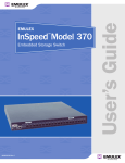
InSpeed
Model 375
TM
SAN Storage Switch
USER’S GUIDE
For Apple Computer Users
embedded in the future of s t o r a g e
VIXEL INSPEED™ SAN STORAGE SWITCH MODEL 375
USER ’S GUIDE
Vixel InSpeed™ SAN Storage Switch Model 375 User’s Guide
Part Number 00041392-001 Rev. A
Copyright © 2003 Vixel Corporation. All rights reserved worldwide. No part of this document may be reproduced
by any means nor translated to any electronic medium without the written consent of Vixel Corporation.
Information furnished by Vixel Corporation is believed to be accurate and reliable. However, no responsibility is
assumed by Vixel Corporation for its use; or for any infringements of patents or other rights of third parties which
may result from its use. No license is granted by implication or otherwise under any patent or patent rights of
Vixel Corporation.
Vixel, InSpeed™, and FibreSpy™ are registered trademarks of Vixel Corporation. All other brand or product names
referenced herein are trademarks or registered trademarks of their respective companies or organizations.
Vixel Corporation provides this manual “as is,” without any warranty of any kind, either expressed or implied,
including but not limited to the implied warranties of merchantability or fitness for a particular purpose. Vixel
Corporation may make improvements and changes to the product described in this manual at any time and
without any notice. Vixel Corporation assumes no responsibility for its use, nor for any infringements of patents or
other rights of third parties that may result. Periodic changes are made to information contained herein; although
these changes will be incorporated into new editions of this manual, Vixel Corporation disclaims any undertaking
to give notice of such changes.
Vixel Corporation, 11911 North Creek Parkway South, Bothell, WA 98011
Vixel Corporation holds US Patent Number 6,118,776 for its SOC 320 technology.
EMBEDDED IN THE FUTURE OF STORAGE
i
VIXEL INSPEED™ SAN STORAGE SWITCH MODEL 375
USER ’S GUIDE
Table of Contents
1
Introduction .................................................................................. 1
2
Switch Installation ......................................................................... 6
3
Switch Management ......................................................................15
4
Technical Reference .......................................................................57
Appendixes ............................................................................. 61
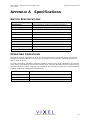
A
Specifications ............................................................................... 62
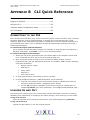
B
CLI Quick Reference ....................................................................... 63
C
Event Messages ............................................................................ 66
D
AL_PA Cross References ................................................................. 68
E
Glossary ...................................................................................... 69
Index ..................................................................................... 70
EMBEDDED IN THE FUTURE OF STORAGE
ii
VIXEL INSPEED™ SAN STORAGE SWITCH MODEL 375
USER ’S GUIDE
C HA PT E R 1 INTRODUCTION
C HAPTER 1 I NTRODUCTION
Overview.................................................... 1
Features .................................................... 2
InSpeed™ Technology .................................. 2
Switch Applications ...................................... 3
Note: Important safety, electromagnetic compatibility, and regulatory information is contained in
the Vixel Safety & Regulatory Guide. The installation and use of this product must be in
accordance with the information provided in that guide.
This guide is designed to provide users with the necessary information to install and manage the
Vixel InSpeed™ SAN Storage Switch Model 375 for use in Fibre Channel applications in typical
entry-level Storage Area Networks (SANs).
OVERVIEW
The Vixel InSpeed™ SAN Storage Switch Model 375 is designed for entry-level Storage Area
Networks (SANs), which provide the following advantages over direct attached storage:
•
Greater application availability
•
Higher performance between servers and storage devices
•
Improved storage asset utilization
•
Lower storage management and support costs
•
Incremental scalability to keep up with difficult to estimate storage growth
This switch is ideal for storage pooling and consolidation, high-performance shared tape library
backup and recovery, server clustering, and streaming rich media applications.
Enclosed in a 1U, full-rack form factor enclosure, the switch is built around the InSpeed™ SOC
320 and is controlled by firmware loaded into the on-board Flash.
The switch is designed as a central interconnect following the ANSI FC-AL standard. Devices are
connected to the switch through Small Form-factor Pluggable (SFP) transceivers and cables. Each
attached node has 1 or 2 Gigabits per second (Gb/s) of Fibre Channel bandwidth. The switch
operates at full switching bandwidth that reaches speeds of 4 GB/s per port and up to 80 Gb/s of
aggregate bandwidth.
Complete switch configuration and management is available through the intuitive, graphicalbased Web Manager interface. A variety of network configurations are easily established using the
switch’s Port Smart Settings, One-Step Zoning, Automatic Trunking, and Load Balancing features.
In addition, the switch features granular change notification management, retained system
configuration parameters, and a Command Line Interface (CLI) for advanced users.
EMBEDDED IN THE FUTURE OF STORAGE
1
VIXEL INSPEED™ SAN STORAGE SWITCH MODEL 375
USER ’S GUIDE
C HA PT E R 1 INTRODUCTION
F EATURES
The Vixel InSpeed™ SAN Storage Switch Model 375 has the following features:
•
•
High Performance Fibre Channel Switching:
•
Wire speed non-blocking Crossbar switch core
•
Single 20-port Vixel InSpeed SOC 320 ASIC with embedded SERDES
•
Multiple simultaneous conversations between ports
•
Traffic routed directly to destination ports
•
2 Gb/s or 1 Gb/s performance across all ports
•
Aggregate bandwidth of 80 Gb/s
•
Supports cascades up to 3 switches and up to 126 host and storage devices
•
No complex fabric services or buffers
•
Effortlessly connects to any vendor’s fabric
Patent-pending technology:
•
Fairness and Prioritization–ensures devices all have guaranteed access, or
explicitly have prioritized access, over all other devices in a system.
•
Stealth TM Intelligent Change Manager–delivers maximum stability through
automatic elimination of state and change notification system disruptions and
unprecedented control of disruptive events.
•
Automatic Trunking–enables fully-multiplied throughput and bandwidth, failover
pathing, and dynamic load balancing and device prioritization.
•
Advanced diagnostics, performance monitoring, and fault isolation including continuous
switch and port monitoring and automatic bypass of problematic or unused ports.
•
Port Smart Settings, which are predefined port-level configurations that optimize switch
performance and stability.
•
One-Step Zoning, including overlapping/non-overlapping zones with port or AL_PA-based
zoning.
•
Switch management using the embedded http-based web server, Command Line Interface
(CLI), or Simple Network Management Protocol (SNMP).
•
Full-rack, 1U size for easy installation (optional 19" rack-mounting kits available).
•
Redundant fans and two hot-swappable, auto-sensing, load sharing, universal power
supplies for high availability.
•
Fibre Channel ANSI Standards Compliance
I N S PEED ™ T ECHNOLOGY
Vixel’s InSpeed™ technology is an advanced switching architecture that couples a non-blocking
crossbar switch with a unique switch port logic and per-port SERDES. This results in the industry’s
highest density Fibre Channel switch on a chip (SOC). The port logic is based on Fibre
Channel-Arbitrated Loop (FC-AL), an ANSI standard (X3T11) designed to provide shared
bandwidth over low-cost media.
This architecture enables the switch’s router to send data directly from one port to another,
allowing for multiple, simultaneous conversations between ports—effectively multiplying
bandwidth. InSpeed™ provides the same performance as complex fabric switches that support
FC-SW2. InSpeed™ can even exceed fabric switch performance in entry-level SAN environments,
where the overhead associated with longer name addressing and services is not beneficial.
EMBEDDED IN THE FUTURE OF STORAGE
2
VIXEL INSPEED™ SAN STORAGE SWITCH MODEL 375
USER ’S GUIDE
C HA PT E R 1 INTRODUCTION
S WITCH APPLICATIONS
The Vixel InSpeed™ SAN Storage Switch Model 375 is ideal for consolidation and shared storage
pooling, high-performance shared tape library backup and recovery, server clustering, and
streaming rich media applications. The following sections provide examples of these applications.
Storage Consolidation and Shared Storage Pooling
In this configuration, the switch enables multiple hosts to share single or multiple storage
systems. This application replaces direct-attached configurations that require multiple storage
systems to be attached to separate servers, which often results in difficult to manage multiple
systems and trapped, unused storage islands (storage cannot be shared with other servers).
Figure 1-1: Before storage consolidation...
and after storage consolidation.
Benefits include:
•
Improved incremental scalability–connect up to 20 hosts and/or other storage devices,
including tape libraries, to a single switch.
•
Lower storage management support costs.
•
Improved capacity utilization that enables effective use of both servers and storage.
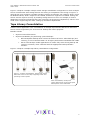
For larger system environments, multiple switches can be connected and Automatic Trunking can
be used to keep performance and availability at high levels. As a best practice when using
multiple switches, connect servers and their related storage devices through the same switch to
optimize performance.
Figure 1-2: Multiple switch storage consolidation diagram
EMBEDDED IN THE FUTURE OF STORAGE
3
VIXEL INSPEED™ SAN STORAGE SWITCH MODEL 375
USER ’S GUIDE
C HA PT E R 1 INTRODUCTION
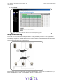
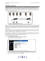
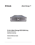
Figure 1-2 depicts a sample multiple switch storage consolidation configuration in which multiple
servers communicate with storage devices and zoning is incorporated. The zoning in Figure 1-2
might be set up to configure a multiple operating system environment. For example, Zone 1 might
be Windows-based, Zone 2 might be Linux-based, and Zone 3 might be Unix-based. Zoning can
also be used to improve security by masking storage devices or files. For example, a finance
department could secure financial files from viewing by the engineering department, which in turn
could secure engineering files from viewing by the finance department.
Tape Library Consolidation
Another switch application is the consolidation of multiple tape libraries attached to individual
servers into a single library for all servers for backup and restore purposes.
Benefits include:
•
Improved cost effectiveness.
•
Improved availability for performing system backups:
•
Off-LAN System Backups often reduce the amount of time it takes backups (and
recovery) to occur because SANs run at higher performance bandwidth than LANs.
•
Server-less backups enable applications to remain fully active during backup and
recovery processes, when combined with the appropriate backup software
solution.
Figure 1-3 depicts a sample tape library consolidation configuration.
Figure 1-3: Before consolidation, backup and restore
data must travel on the LAN, congesting traffic and
operating at slow speeds.
After consolidation, backup and
restore data travels on the high speed
SAN separate from LAN traffic.
EMBEDDED IN THE FUTURE OF STORAGE
4
VIXEL INSPEED™ SAN STORAGE SWITCH MODEL 375
USER ’S GUIDE
C HA PT E R 1 INTRODUCTION
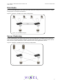
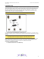
Rich Media
For rich media applications, the switch provides improved storage and file sharing from a single
storage pool for multiple workstations.
Figure 1-4 depicts a sample rich media configuration.
Figure 1-4: Rich media diagram
Server Clustering
In this configuration, the switch helps deliver improved application availability when combined
with a server clustering software solution, like Microsoft Cluster Server or Veritas Cluster Server.
This prevents system downtime in case of failure to one of the application servers.
Figure 1-5 depicts a sample server clustering configuration.
Figure 1-5: Server clustering diagram
EMBEDDED IN THE FUTURE OF STORAGE
5
VIXEL INSPEED™ SAN STORAGE SWITCH MODEL 375
USER ’S GUIDE
CHAPTER 2 SWITCH INSTALLATION
C HAPTER 2 S WITCH INSTALLATION
Installation Preparation ................................ 6
Switch Installation ....................................... 7
Switch LEDs ............................................... 9
SFP Compatibility ...................................... 12
Booting the Switch and SAN ........................ 13
Power Supply/Fan Module Replacement ........ 14
I NSTALLATION PREPARATION
After receiving the switch, perform the following steps to ensure the switch and other contents
arrived safely.
To unpack the switch:
1. Inspect the outer shipping container for any damage that may have occurred in shipping.
Report any sign of damage to the appropriate shipping agency.
2. Remove the switch and cables from the shipping container; save the shipping container,
foam, and antistatic bags—returning the switch in any other container is not advised.
Make sure the following parts are included:
•
Switch unit
•
RS-232 null-modem serial cable
•
Power cables (2)
•
Self-adhesive pads (4)
•
Retention clips (2), screws (4), and washers (4) for securing the power cords to
the switch.
•
Vixel InSpeed™ SAN Storage Switch Model 375 Quick Install Card
•
Product Release Notes
•
Vixel Safety and Regulatory Guide
•
Additional documentation, including warranty information and the End User
License Agreement.
3. Inspect the switch thoroughly. (If any signs of damage are seen, notify a sales
representative and/or the shipping agency.)
EMBEDDED IN THE FUTURE OF STORAGE
6
VIXEL INSPEED™ SAN STORAGE SWITCH MODEL 375
USER ’S GUIDE
CHAPTER 2 SWITCH INSTALLATION
S WITCH INSTALLATION
The switch may be placed on a desktop or installed in a rack.
Desktop Installation
To place the switch on a desktop:
1. Turn the switch upside down so the case bottom is facing up.
2. Install a self-adhesive pad (included) on each corner of the switch bottom approximately 1
inch from each side (prevents surface damage).
3. Turn the switch right-side up so the case bottom is facing down and place the switch on a
stable table or platform.
Note: Important safety, electromagnetic compatibility, and regulatory information is
contained in the Vixel Safety & Regulatory Guide. The installation and use of
this product must be in accordance with the information given in that guide.
For information on environmental requirements, see “Operating Conditions” on page 62.
Rack Installation
Installing the switch in an equipment rack requires an optional rack mount kit (sold separately).
There are two kit variations currently available:
•
24-inch Full Rack Mount Kit (Part Number 00651382), which supports equipment rack
depths from 22 to 29 inches.
•
30-inch Full Rack Mount Kit (Part Number 00651383), which supports equipment rack
depths from 29 to 36 inches.
The rack mount kit includes all the necessary hardware and installation instructions for properly
installing a switch into an equipment rack. Contact a sales representative for more information or
assistance in purchasing a kit.
UL Guidelines for Mounting Equipment in a Rack
When installing equipment in a rack, give careful consideration to the following factors:
•
The operating ambient temperature of rack-mounted equipment must not exceed the
maximum rated ambient temperature, which is indicated in this installation guide. (See
“Operating Conditions” on page 62.)
•
The air flow clearances specified in this installation guide must be maintained within the
rack. (See “Operating Conditions” on page 62.)
•
The AC supply circuit for rack-mounted equipment must be capable of supplying the total
current specified on all the labels of the rack-mounted equipment.
•
All AC power supply connections must be properly earthed. To ensure the integrity of the
earth connection, special attention must be given to connections that are not directly
connected to the branch circuit (for example, power strips).
•
The rack-mounting hardware has been carefully selected to properly support the
equipment. Any alternate rack-mounting hardware must provide equal or superior
support.
EMBEDDED IN THE FUTURE OF STORAGE
7
VIXEL INSPEED™ SAN STORAGE SWITCH MODEL 375
USER ’S GUIDE
CHAPTER 2 SWITCH INSTALLATION
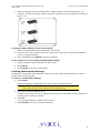
Installing the Retention Clips (optional)
The switch ships with two, optional retention clips to secure the power cords in each power
supply/fan module’s power receptacle. Screws (4) and washers (4) are provided for the clips.
To install the retention clip:
1. Secure the retention clip to the switch by aligning the retention clip with the two screw
holes located to the left and the right of the module’s power receptacle. The retention clip
mounting loops should be facing downward.
2. Place the washer on the screw prior to inserting the screw through the retention clip’s
mounting loop.
3. Using a screwdriver, tighten the screws to secure the retention clip to the power supply/
fan module.
To insert the power cord with the retention clip in place:
1. Insert the power cord plug into the module’s power receptacle. The plug must initially be
inserted into the receptacle at an angle to avoid the retention clip.
2. Once the power cord plug is firmly inserted in the module’s power receptacle, the
retention clip fastens over the end of the power cord plug to secure it in the power
receptacle.
To remove the power cord with the retention clip in place:
Press down on the retention clip while removing the power cord from the module’s power
receptacle.
EMBEDDED IN THE FUTURE OF STORAGE
8
VIXEL INSPEED™ SAN STORAGE SWITCH MODEL 375
USER ’S GUIDE
CHAPTER 2 SWITCH INSTALLATION
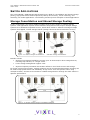
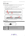
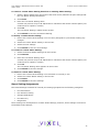
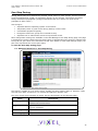
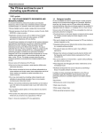
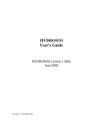
S WITCH LED S
The switch incorporates four sets of Light-Emitting Diodes (LEDs) to indicate ethernet, switch,
port, and power supply/fan module status:
1. Ethernet LEDs – two separate LEDs indicating the network connection status.
2. System LEDs – four separate LEDs indicating the switch’s status.
3. Port LEDs – two LEDs per port indicating the port’s status.
4. Power Supply/Fan LED – a separate LED for each power supply/fan module indicating the
power supply/fan module’s status.
Ethernet LEDs
System LEDs
Port LEDs
Figure 2-1: Switch View Depicting Ethernet, Port, and System LEDs
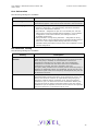
Power Supply/Fan LED
Power Supply/Fan LED
Figure 2-2: Switch View Depicting Power Supply/Fan LED
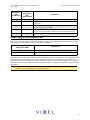
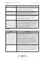
Ethernet LEDs
The Ethernet LEDs indicate the network connection status:
Ethernet Activity
Ethernet Link
Figure 2-3: Ethernet LEDs
Ethernet LEDs
Indication
Ethernet Activity
(green LED)
• When flashing, the ethernet port is receiving data.
Ethernet Link
(green LED)
When lit, the switch is connected to an operational ethernet.
• When flashing rapidly, the traffic level is high.
EMBEDDED IN THE FUTURE OF STORAGE
9
VIXEL INSPEED™ SAN STORAGE SWITCH MODEL 375
USER ’S GUIDE
CHAPTER 2 SWITCH INSTALLATION
System LEDs
The System LEDs indicate the switch’s status, independent of the port LEDs.
Fault
Power
2 Gb/s
Switch Operational
Figure 2-4: System LEDs
System LEDs
Fault
(yellow LED)
Indication
• When lit, one or more of the ports has failed or the internal temperature has
exceeded acceptable levels.
• When flashing, all ports are operational but another error has occurred. Errors
appear in an event log. The level of error severity that will cause flashing to start
can be controlled using the config sys fault command in the CLI. The default is
level 3, Critical.
Note: Whether lit or flashing, the switch will continue to operate. Switch functionality
may be impaired depending on the event that triggered the Fault LED. Regardless of
the cause, the switch requires immediate attention.
Power
(green LED)
When lit, the switch is plugged in and the internal power supplies are functional.
2 Gb/s
(green LED)
When lit, the switch is set to operate at a speed of 2 Gb/s. When off, the switch is
set to 1 Gb/s.
Switch
Operational
(green LED)
• When lit, indicates that the switch has completed initialization for ports with
inserted SFPs and that the switch is operational.
• When flashing, the switch has been configured for multiple zones, and one or
more zones are up with at least one zone down.
If no zones (excluding hard zones) are operational, the LED turns off.
Port LEDs
The Port LEDs indicate the port’s status. Each port has two LEDs:
•
SFP Status LED
•
Port Bypassed LED
Port Bypassed
SFP Status
Figure 2-5: Ethernet LEDs
SFP Status
LED
(green LED)
Port
Bypassed
LED
(yellow LED)
Indication
Off
Off
Normal port operational status when an SFP is not installed.
Off
On or Flashing
The port is bypassed due to a faulty or improperly seated SFP. After
fixing this problem, power may need to be cycled before the LED
indication will change.
EMBEDDED IN THE FUTURE OF STORAGE
10
VIXEL INSPEED™ SAN STORAGE SWITCH MODEL 375
USER ’S GUIDE
SFP Status
LED
(green LED)
Port
Bypassed
LED
(yellow LED)
CHAPTER 2 SWITCH INSTALLATION
Indication
Flashing
Off
Activity. Data is being transferred between the port and device.
On
Off
Normal operation but no activity. Port and device are fully
operational.
On
Flashing
Manually bypassed. A port can be manually bypassed using the Web
Manager’s Bypass Port feature.
On
On
Bypassed. SFP is installed but the port is not receiving a valid signal
or is receiving an F8 Failure notification from the attached device.
Flashing
Flashing
Beaconing. This is set manually using the Web Manager or CLI.
Power Supply/Fan Module LED
The switch uses two power supply/fan modules to guarantee high availability with failover. Each
power supply has a separate LED to indicate its condition.
Power Supply/Fan Module
LED (green LED)
Indication
On
No faults exist and AC power is supplied to the module.
Off
A power supply or fan fault has occurred in the module.
When a power supply or fan fault occurs, the switch will continue to operate normally as long as
the faulty power supply/fan module remains installed in the switch and there are at least two fans
operational in each module. If the power supply/fan module is removed from the switch, the
switch will continue to operate normally for approximately 20-30 minutes. However, to guarantee
continued operation, the malfunctioning module should be immediately replaced to maintain high
availability.
Note: Keeping spare power supply/fan modules (Part Number 601319) in stock is highly recommended.
Contact a sales representative for further information.
EMBEDDED IN THE FUTURE OF STORAGE
11
VIXEL INSPEED™ SAN STORAGE SWITCH MODEL 375
USER ’S GUIDE
CHAPTER 2 SWITCH INSTALLATION
SFP C OMPATIBILITY
SFPs are “hot-pluggable” into the switch, which allows host computers, servers, and storage
devices to be added dynamically without requiring power removal from the switch or any
connected devices.
The switch supports Small Form-Factor Pluggable (SFP) modules that comply with the SFP
specification as produced by the MSA consortium and have passed Vixel’s qualification testing.
The following manufacturers of 1-2Gb optical, shortwave SFPs are recommended:
•
Finisar
•
JDS Uniphase
Contact a customer service representative to request the certified part numbers for these
vendors.
Installing an SFP
If the Change Notification on Insertion policy is enabled, plugging an SFP into the switch will
automatically send an F7 Initialization notification to indicate the device is ready to begin
initialization.
Caution: Forcing an SFP into a port may damage the SFP and/or port.
To insert an SFP:
1. Remove dust covers or plugs from the SFPs, if provided.
2. Slide the SFP into the port, ensuring correct polarity, until the latch clicks into place.
Removing an SFP
To extract an SFP:
Determine what kind of extraction mechanism the SFP has and remove the SFP as follows:
If the SFP has a removal tag, remove the cable from the SFP and then pull the removal tag
outward and toward the side of the SFP with the tag.
If the SFP has a small plastic slider on the top or bottom, remove the cable from the SFP and
then push in the slider and hold while pulling out the SFP.
If the SFP has a bale (small metal clasp), remove the cable from the SFP and then unlatch,
pivot, and pull the bale.
Attaching a Device to the Switch
To attach a device:
1. Make sure that the device is FC-AL compatible.
2. Attach a cable to the device.
3. Attach the other end of the cable to an SFP.
4. Make sure that the device and switch are operational and set to the same speed.
EMBEDDED IN THE FUTURE OF STORAGE
12
VIXEL INSPEED™ SAN STORAGE SWITCH MODEL 375
USER ’S GUIDE
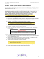
BOOTING
THE
S WITCH
AND
CHAPTER 2 SWITCH INSTALLATION
SAN
The following procedure is recommended when booting the switch and SAN. Before powering on
the switch and SAN, read the Release Notes, included with the switch contents, to determine any
modifications that may be required for a specific installation.
To boot the switch and SAN:
1. Power on the storage devices (such as JBODs, tape libraries, and RAIDs).
2. Insert the plug end of the switch’s power cord to a properly grounded power source.
3. Insert the power cord’s IEC connector end into the switch’s power receptacle.
The switch powers on and runs Power-On Self-Test (POST) diagnostics to verify the
fundamental integrity of the switch ports. All switch LEDs turn on (LEDs illuminate). Then,
excluding the Ethernet Link, Power Supply/Fan Module, and Power LEDs, the LEDs turn off
(LEDs extinguish). Once the switch is operational, the LEDs display current status as
described in “Switch LEDs” on page 9.
Note: The power cord’s IEC connector plug serves as the switch’s disconnect device.
To cycle power to the switch, remove and reconnect the switch’s power cord.
4. Power on any other switches connected to the SAN.
5. For certain applications, switch configuration must be completed before continuing with
the next step. For information regarding switch configuration, see Chapter 3: Switch
Management.
6. After all switches have initialized, power on the hosts.
The network initializes.
Note: FC-AL compatible nodes must perform initialization procedures upon power-up
in order to function properly. It is the responsibility of the Fibre Channel driver
software on FC-AL nodes to perform this initialization.
7. Check all port LEDs.
The SAN should be fully operational at this point. However, it is appropriate to ensure
proper discovery has taken place and all required devices are participating in the network.
Some host bus adapters may provide this level of functionality or it might be resident in
the application software on the host operating system.
EMBEDDED IN THE FUTURE OF STORAGE
13
VIXEL INSPEED™ SAN STORAGE SWITCH MODEL 375
USER ’S GUIDE
CHAPTER 2 SWITCH INSTALLATION
P OWER S UPPLY /F AN M ODULE R EPLACEMENT
The Vixel InSpeed™ SAN Storage Switch Model 375 has hot-swappable power supply/fan modules
for high availability. A power supply/fan module consists of an individual power supply and a fan
bank consisting of three fans.
The switch can run on one functioning power supply/fan module indefinitely, as long as the faulty
power supply/fan module remains installed in the switch and there are at least two fans
operational in each module’s fan bank. If the power supply/fan module is removed from the
switch, the switch will continue to operate normally for approximately 20-30 minutes. Nonfunctional modules should be immediately replaced to maintain high availability.
Note: Keeping spare power supply/fan modules (Part Number 601319) in stock is highly
recommended. Contact a sales representative for further information.
To remove an old power supply/fan module:
1. Have the new power supply/fan module close to the switch for quick insertion. (This step
ensures that the procedure takes no longer than necessary—the switch can only operate
with one power supply/fan module installed for approximately 20-30 minutes.)
2. Unplug the power cord from the faulty module’s power receptacle.
Note: The alternate power supply/fan module should remain powered on while the
faulty module is removed and replaced to guarantee switch availability.
3. Slide the safety latch over the power receptacle to expose the thumb screw.
4. Loosen the two thumb screws. No tools are required.
5. Pull the unscrewed power supply/fan module out of the switch’s module bay using the
module’s handle.
WARNING
To avoid an electrical hazard, never apply power to the power
supply/fan module while the module is removed from the switch.
To insert a new power supply/fan module:
1. Align the power supply/fan module with the module bay opening. Ensure the warning label
is facing upwards on the module.
2. Carefully slide the module into the opening. Ensure the module is seated firmly in the
module bay (the module should be flush with the switch’s face).
3. Tighten the two thumb screws. No tools are required.
Note: When using a screwdriver to tighten the thumb screws, ensure the thumb
screws are secure but not overtightened. Overtightening the thumb screws may
damage the screws or the module.
4. Slide the safety latch over the thumb screw (uncovering the power receptacle).
5. Plug the power cord into the module’s module power receptacle.
EMBEDDED IN THE FUTURE OF STORAGE
14
VIXEL INSPEED™ SAN STORAGE SWITCH MODEL 375
USER ’S GUIDE
CHAPTER 3 SWITCH MANAGEMENT
C HAPTER 3 S WITCH MANAGEMENT
Getting Started ......................................... 16
Managing the Switch .................................. 21
Monitoring the Switch ................................ 48
This chapter is divided into three sections providing information on how to manage and monitor
the switch:
•
Getting Started – Describes how to configure the network interface, use the Web
Manager, and perform a basic initial setup of the switch.
•
Managing the Switch - Describes how to configure the switch and port settings, manage
firmware versions and configuration files, set switch thresholds, and configure One-Step
Zoning, Automatic Trunking, and Load Balancing.
•
Monitoring the Switch – Describes how to view switch information, the event log, port
information, and port diagnostics.
The switch incorporates two distinct interfaces for managing and monitoring purposes:
•
The Web Manager interface provides an intuitive graphical user interface that enables
users to quickly check switch status or modify switch settings in a visual environment.
•
The Command Line Interface (CLI) provides flexibility and additional functionality for
advanced users.
Both of these interfaces provide nearly identical functionality; however, for the purposes of this
guide, the Web Manager interface is used for switch and port configuration unless otherwise
noted.
For a list of CLI commands, see Appendix B: CLI Quick Reference on page 63. For additional
information on the CLI, see the InSpeed Storage Switch CLI Reference Guide.
EMBEDDED IN THE FUTURE OF STORAGE
15
VIXEL INSPEED™ SAN STORAGE SWITCH MODEL 375
USER ’S GUIDE
CHAPTER 3 SWITCH MANAGEMENT
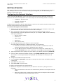
G ETTING STARTED
This section explains how to configure the switch’s ethernet network settings prior to using the
Web Manager. Once the switch’s network settings are configured, use the Web Manager to
perform a quick switch setup.
Configuring the Network Interface
Before using the Web Manager, ensure the switch’s ethernet network parameter settings are
correct for the network configuration. The switch ships with the following default IP settings:
•
IP Address: 169.254.10.10
•
Netmask: 255.255.0.0
•
Gateway: 0.0.0.0
To adjust these settings to open the Web Manager, connect to the switch using the provided serial
interface cable and follow the instructions below.
To connect through a serial interface:
1. Attach one end of the included RS-232 null modem cable to the computer’s DB-9 serial
port and attach the other end to the switch’s DB-9 serial port.
2. Open a terminal session through a serial terminal emulation program (such as
HyperTerminal®) with the appropriate serial port (for example, COM1) and the following
serial port parameters:
•
Bits per second: 19200
•
Data bits: 8
•
Parity: None
•
Stop bits: 1
•
Flow control: None
3. If using HyperTerminal, press ENTER to receive a prompt.
If using the tip command on a UNIX workstation, do the following:
a.
View the /etc/remote file and create an alias similar to Hardware but with the
serial port parameters above. (Suggested name: Switch)
b. Use the tip command to establish a connection through the created alias, for
example tip switch. (For more information, see the tip command Manual page.)
4. Type the password at the prompt and press ENTER. (The default password is password.)
5. From the serial terminal emulation program, type config network ip and press E NTER.
The switch’s current IP parameters are displayed with a prompt for entering the IP
address.
6. Change the IP address and press ENTER.
7. Use the mask and gateway commands to change the subnet mask and default gateway
respectively.
8. Type save and press ENTER.
9. Type root reset and press E NTER.
10. Type y and press ENTER to reset the switch.
11. Attach the computer to the switch’s 10/100 ethernet connector by doing one of the
following:
•
Attach an ethernet RJ-45 cross-over cable directly between the computer and the
switch.
•
Attach two ethernet RJ-45 twisted pair cables from the computer and the switch
into an operational ethernet patch panel or hub.
EMBEDDED IN THE FUTURE OF STORAGE
16
VIXEL INSPEED™ SAN STORAGE SWITCH MODEL 375
USER ’S GUIDE
CHAPTER 3 SWITCH MANAGEMENT
Connecting to the Web Manager
The Web Manager displays current port utilization and health, enables easy to use Port Smart
Settings and One-Step Zoning, and several additional features discussed later in this chapter.
Note: The Web Manager supports the Microsoft Internet Explorer version 5.5 or later web
browser on Windows or Apple OS-X operating systems.
To connect to the Web Manager:
1. Ensure the workstation has access to the network on which the switch is connected.
2. Open Microsoft Internet Explorer, version 5.5 or later.
3. In the address bar, type the switch’s DNS name or IP address and press E NTER.
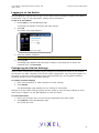
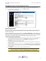
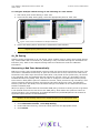
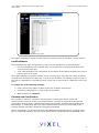
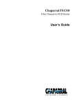
Web Manager Overview
The Web Manager enables users to view and configure switch and port settings using an intuitive,
graphical user interface. The main page is the Switch Information page. This page displays
general switch status and continually refreshes to display the most current switch status. For
more information on the Switch Information page, see “Switch Information” on page 48.
To return to this page at any time, click the InSpeed™ Storage Switch menu item.
Command
buttons
Navigation Menu
Current page
information
Figure 3-1: Web Manager interface
Note: The web browser’s appearance and information depends on the switch’s active
firmware version and may change without notice in subsequent firmware versions.
The Web Manager interface consists of a series of command buttons, an expandable navigation
menu, and the displayed information area. The command buttons and navigation menu are
always present on the page.
Command Button
Description
Submit
Saves any changes made to the switch configuration. This button is
disabled until a configuration setting is changed or new information is
entered. This button appears green to notify the user of a change to the
switch configuration. Click this button to accept the configuration change.
Cancel
Cancels a request. This button is disabled until a configuration setting is
changed or new information is entered. This button appears green to
notify the user of a change to the switch configuration. Click this button to
cancel the configuration change.
EMBEDDED IN THE FUTURE OF STORAGE
17
VIXEL INSPEED™ SAN STORAGE SWITCH MODEL 375
USER ’S GUIDE
Command Button
CHAPTER 3 SWITCH MANAGEMENT
Description
Reboot
Resets the switch.
Login/Logout
Logs in to and out of the switch.
Refresh
Redraws the currently displayed web page.
The expandable navigation menu provides several options for configuring and monitoring the
switch. The menu uses a tree-based navigation structure with a list of menu options and items.
Clicking a menu option with a "+" next to it expands the menu option and displays additional
menu items. Clicking a menu item displays the selected Web Manager page.
To ensure that the most current information is displayed, use the navigation menu instead of the
browser’s Back and Next buttons, which usually display cached copies and may not reflect current
switch information.
To log out of the Web Manager, click Logout, or simply close the browser window.
Note: The Web Manager will automatically log users out after 15 minutes of inactivity, unless
the Switch Information page is currently displayed. The Switch Information page
automatically updates to display the most current switch status.
Documentation
The Web Manager’s Help menu provides links to online product documentation and firmware
downloads.
To access product documentation:
1. Click Help > Documentation.
2. Click Product Docs.
A documentation request web page appears.
3. Enter the appropriate information and click Submit Request.
An email message is sent to the provided email address with the web page location for the
requested product documentation.
To view Technical Brief documentation, click Technical Briefs.
To download firmware:
1. Click Help > Downloads.
A download request web page appears.
2. Enter the appropriate information and click Submit Request.
An email message is sent to the provided email address with the web page location for the
requested firmware download.
EMBEDDED IN THE FUTURE OF STORAGE
18
VIXEL INSPEED™ SAN STORAGE SWITCH MODEL 375
USER ’S GUIDE
CHAPTER 3 SWITCH MANAGEMENT
Initial Switch Setup
Once a network connection has been established with the switch and an instance of the Web
Manager is open, some basic switch configuration tasks are recommended:
•
Log in to the switch.
•
Change the switch’s password.
•
Verify the switch’s date and time settings.
•
Change the switch’s name.
For additional information on Web Manager features and functionality, see “Managing the Switch”
on page 21 and “Monitoring the Switch” on page 48.
Step 1: Log in to the Switch
The switch incorporates a password-level security system to prevent unwanted changes to the
current switch configuration. In order to make any changes to the switch, users must be logged in
to the switch.
To log in to the switch:
1. Click Login on any Web Manager page.
A message box appears confirming the login request.
2. Click OK.
The switch login page appears.
3. Enter the switch’s password.
The default password is "password".
4. Click Log In.
A message page appears while the page is loading. If the page fails to load in the
indicated time, click Continue.
See “Logging in to the Switch” on page 22 for additional information.
Step 2: Change the Password
The default password is set at the factory to "password". Change the default password to secure
the switch and guarantee that any configuration changes are only performed by registered users.
To change the password:
1. Click Switch > Password.
The Switch Password page appears.
2. Enter the new password in the New Password text box.
Note: The password must be between 6 and 25 characters in length and is case
sensitive.
3. Enter the new password again in the Confirm New Password text box.
4. Click Submit.
A message box appears confirming the change to the switch’s configuration.
5. Click OK.
The Password set success message appears confirming that the new password was saved
and activated.
See “Changing the Password” on page 27 for additional information.
EMBEDDED IN THE FUTURE OF STORAGE
19
VIXEL INSPEED™ SAN STORAGE SWITCH MODEL 375
USER ’S GUIDE
CHAPTER 3 SWITCH MANAGEMENT
Step 3: Verify the Date and Time
During the initial Web Manager session, the date and time for the switch are set based on the host
system’s current settings.
To view the current date and time:
1. Click Switch > Date & Time.
The Switch Date & Time page appears.
To set the date and time settings:
1. Enter the new date and time settings in the appropriate fields.
2. Click Submit.
The new date and time appear under Current Date & Time.
To synchronize the current date and time settings with the host system:
1. Click Host Time.
The date and time of the current host system appear in the New Date & Time text box.
2. Click Submit.
The new date and time appear under Current Date & Time.
See “Configuring Date and Time Settings” on page 26 for additional information.
Step 4: Change the Switch Name
While not required, changing the switch’s name is recommended for identification and
troubleshooting purposes.
To change the switch name:
1. Click Switch > Configuration.
The Switch Configuration page appears.
2. Enter the new name in the Name text box.
3. Click Submit.
The new name appears in the Name text box and also appears in the title bar after the
"InSpeed™" label.
Note: The web page may have to be refreshed before seeing the name change. Press
F5 to refresh the web browser instance or open a new web browser instance.
See “Switch Identification” on page 23 for additional information.
EMBEDDED IN THE FUTURE OF STORAGE
20
VIXEL INSPEED™ SAN STORAGE SWITCH MODEL 375
USER ’S GUIDE
MANAGING
THE
CHAPTER 3 SWITCH MANAGEMENT
S WITCH
The Vixel InSpeed™ SAN Storage Switch Model 375 provides several options for managing and
configuring the switch to meet the needs of the network environment.
This section describes how to log in to the switch, configure switch and port settings, manage
firmware and configuration files, and configure One-Step Zoning, Automatic Trunking, and Load
Balancing.
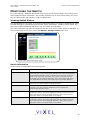
Frequent Switch Configuration Tasks
A list of frequent switch configuration-related tasks is provided below. The list displays the task,
the corresponding Web Manager command, and a reference to where more information may be
found in this guide.
To…
Click…
In this guide, see...
View switch status
InSpeed™ Storage
Switch
“Viewing Switch Status” on page 48.
Change general switch
configuration
Switch > Configuration
“Configuring the Switch Settings” on
page 22.
Change the IP Address
Switch > Configuration
“Network Location” on page 23
Change the switch speed
Switch > Configuration
“Switch Speed” on page 24.
View the event log
Switch > Event Log
“Viewing the Event Log” on page 50.
Configure traps
Switch > SNMP Traps
“Setting SNMP Traps” on page 25.
Upgrade the firmware
Switch > Files
“Switch Firmware Files” on page 36.
Change the Port Smart
Settings
Port > Smart Settings
“Configuring the Port Smart Settings” on
page 29.
Configure One-Step Zoning
Advanced Functions >
One-Step Zoning
“One-Step Zoning” on page 38.
Configure Automatic
Trunking
Advanced Functions >
Automatic Trunking
“Automatic Trunking” on page 45.
Configure Load Balancing
Advanced Functions >
Load Balancing
“Load Balancing” on page 46.
Reset the switch
Reboot
“Configuring the Switch Settings” on
page 22.
For information on viewing switch status and information, see “Monitoring the Switch” on
page 48.
EMBEDDED IN THE FUTURE OF STORAGE
21
VIXEL INSPEED™ SAN STORAGE SWITCH MODEL 375
USER ’S GUIDE
CHAPTER 3 SWITCH MANAGEMENT
Logging in to the Switch
The Web Manager requires users to log in to the switch when changes are made to the switch’s
configuration. Log in is not required for viewing switch information.
To log in to the switch:
1. Click Login on any Web Manager page.
A message box appears confirming the login request.
2. Click OK.
The Switch Login page appears.
Figure 3-2: Switch Login page
3. Enter the switch’s password.
Note: If you do not remember the password, contact a customer service representative.
4. Click Log In.
A message page appears while the page is loading. If the page fails to load in the
indicated time, click Continue.
Configuring the Switch Settings
Several switch configuration settings may be changed to customize the switch to the network
environment. To make a change to the current switch configuration, users must be logged in to
the switch or know the switch password (the switch prompts users for the password before
accepting changes to any configuration settings).
To change a switch setting:
1. Enter new information or make changes to current settings.
2. Click Submit.
The Web Manager page displays the new settings or information.
Changes to certain switch settings require that the switch be reset for those changes to occur.
Users must be logged in to the Web Manager to reset the switch.
To reset the switch:
1. Ensure any changes to the current switch configuration have been saved.
2. Click Reboot on the Web Manager page.
The switch will reset.
EMBEDDED IN THE FUTURE OF STORAGE
22
VIXEL INSPEED™ SAN STORAGE SWITCH MODEL 375
USER ’S GUIDE
CHAPTER 3 SWITCH MANAGEMENT
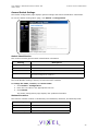
General Switch Settings
The Switch Configuration page displays general settings and switch identification information.
To view the Switch Configuration page, click Switch > Configuration.
Figure 3-3: Switch Configuration page
Switch Identification
This section includes general switch identification information.
Setting
Description
Name
The name of the switch.
Location
The location of the switch.
Contact Name
The person or group to contact about the switch.
Serial Number
A unique identification number assigned to each switch at the factory.
Cannot be configured or modified.
The name, location, and contact name information may be modified for the network environment.
The Serial Number setting is factory set and cannot be modified.
To change the name, location, or contact name:
1. Click Switch > Configuration.
2. Enter the new value in the appropriate text box.
3. Click Submit.
The Switch Configuration page displays the updated information.
Network Location
The switch’s network location is identified by the IP Address, Netmask, and Gateway fields.
Setting
Description
Ethernet IP Address
The current IP Address for the switch.
Netmask
The current IP Netmask address for the switch.
Default Gateway
The current Gateway address for the switch.
EMBEDDED IN THE FUTURE OF STORAGE
23
VIXEL INSPEED™ SAN STORAGE SWITCH MODEL 375
USER ’S GUIDE
CHAPTER 3 SWITCH MANAGEMENT
To change the switch’s network location settings:
1. Click Switch > Configuration.
2. Enter the new value in the appropriate text box.
3. Click Submit.
The Switch Configuration page displays the updated information.
Version Information
The different software and hardware versions include:
Setting
Description
MAC ID
A unique device address (MAC address) assigned to each switch at the
factory. Cannot be configured or modified.
Switch FW Version
The current firmware loaded onto the switch.
Switch HW Version
The hardware version of the switch. Cannot be configured or modified.
InSpeed SOC Version
The SOC 320 version that is used in the switch. Cannot be configured or
modified.
MIB Version
The proprietary Management Information Base version that is supported
through SNMP. Cannot be configured or modified.
Switch Speed
The Switch Speed setting indicates the current speed per port at which the switch is running. All
ports operate at the same speed. The default switch speed is set to 2.125 Gb/s.
To change the switch speed:
1. Click Switch > Configuration.
2. Select the desired speed.
Setting
Description
1 Gb/s
Set switch speed to 1.0625 Gb/s.
2 Gb/s
Set switch speed to 2.125 Gb/s.
3. Click Submit.
Blocking ARB
When two ports start a communication session, the Blocking ARB is sent to all other ports trying
to communicate with those ports until the connection is terminated. The default setting is "FF". If
other connected devices use the "FF" setting for another purpose, select another Blocking ARB
value (for example, "FB"). Under normal circumstances, this setting does not need to be modified.
Agent Up Time
The Agent Up Time field displays the duration of time that the switch has been operational. If the
switch is rebooted or power is cycled, this value is reset.
The Agent Up Time field is for display purposes and cannot be configured.
EMBEDDED IN THE FUTURE OF STORAGE
24
VIXEL INSPEED™ SAN STORAGE SWITCH MODEL 375
USER ’S GUIDE
CHAPTER 3 SWITCH MANAGEMENT
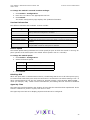
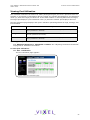
Setting SNMP Traps
Simple Network Management Protocol (SNMP) uses traps to transmit information to SNMP-based
network administration programs. The Switch SNMP Trap Configuration page displays information
on the switch’s current SNMP trap configuration.
To view the SNMP trap configuration page, click Switch > SNMP Traps.
Figure 3-4: Switch SNMP Trap Configuration page
To configure an SNMP trap:
1. Enter the Trap IP address for the device to which the trap information will be sent.
2. Enter the Trap Port number.
This value is usually set to "162" for Windows and Apple-based networks.
3. Select the State.
State
Description
Active
The trap sends messages to the host identified in the IP Address
selection.
Inactive
The trap is not operational.
Delete
The trap will be deleted from the table once changes are saved.
4. Click Submit.
When editing a registered IP address, delete the current IP address and create a new entry for
the revised IP address.
EMBEDDED IN THE FUTURE OF STORAGE
25
VIXEL INSPEED™ SAN STORAGE SWITCH MODEL 375
USER ’S GUIDE
CHAPTER 3 SWITCH MANAGEMENT
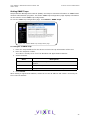
Configuring Date and Time Settings
The Switch Date & Time page displays the switch’s current date and time. During the initial Web
Manager session, the date and time for the switch are set based on the host system’s current
settings. If the switch is rebooted or power is cycled, the system clock will reset and the switch’s
date and time settings will be set to the host system’s time settings of the next user to log in to
the switch.
To change the time:
1. Click Switch > Date & Time.
The Switch Date & Time page appears.
Figure 3-5: Switch Date & Time page
2. Enter the desired date and time in the appropriate fields.
3. Click Submit.
The new date and time appear under Current Date & Time.
To synchronize time with the host system:
1. Click Host Time.
The date and time of the current host system appear in the New Date & Time text box.
2. Click Submit.
The new time appears under Current Date & Time.
EMBEDDED IN THE FUTURE OF STORAGE
26
VIXEL INSPEED™ SAN STORAGE SWITCH MODEL 375
USER ’S GUIDE
CHAPTER 3 SWITCH MANAGEMENT
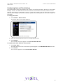
Changing the Password
The Switch Password page enables users to change the password for modifying the switch’s
configuration. The same password is used to access both the Web Manager and the CLI.
Note: Until the default switch password is changed, any user with knowledge of the default
password can make changes to the switch’s configuration.
To change the password:
1. Click Switch > Password.
The Switch Password page appears.
Figure 3-6: Switch Password page
2. Type the new password in the New Password text box.
Note: The password must be between 6 and 25 characters in length and is case sensitive.
3. Type the password again in the Confirm New Password text box.
4. Click Submit. If users are not logged in to the switch, a password prompt appears
requesting that the current password be entered. Enter the current password to proceed.
A message displays confirming that the password was saved and activated.
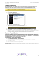
Opening a Telnet Session
Some switch operations may require advanced features currently not found in the Web Manager.
These features are available in the Command Line Interface (CLI), which can be accessed through
the Web Manager by opening a telnet session to the switch.
To open a telnet session with the switch:
1. Click Advanced Functions > Telnet Session.
A message box appears confirming the opening of a telnet session to the switch.
2. Click OK to proceed.
3. Enter the switch’s password and press ENTER.
For additional information on CLI features and functionality, see the InSpeed Storage Switch CLI
Reference Guide.
EMBEDDED IN THE FUTURE OF STORAGE
27
VIXEL INSPEED™ SAN STORAGE SWITCH MODEL 375
USER ’S GUIDE
CHAPTER 3 SWITCH MANAGEMENT
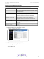
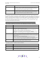
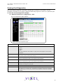
Adjusting the Switch Thresholds
The Switch Thresholds page displays a variety of switch threshold settings.
Setting
Description
Ordered Set Error Threshold
The maximum number of OS errors allowed in a 10-second interval
before a port is bypassed. Setting this value to "0" returns it to the
factory default setting.
This setting is activated on the Port Smart Settings page.
CRC Error Threshold
The maximum number of CRC errors allowed in a 10-second interval
before a port is bypassed. Setting this value to "0" returns it to the
factory default setting.
This setting is activated on the Port Smart Settings page.
Bad Zone Recovery Hold Time
(measured in centi-seconds)
The amount of time that the switch keeps the ports in bypass mode
before attempting to re-insert the ports into the zone.
This setting is activated on the Advanced Functions One-Step
Zoning page.
Bad Zone Recovery Delay Time
(measured in seconds)
The amount of time that the switch waits after a zone goes down
before attempting to recover the zone.
This setting is activated on the Advanced Functions One-Step
Zoning page.
Port Utilization Interval
(measured in seconds)
The length of time between readings of the current port’s
utilization.
To view the current threshold settings:
Click Advanced Functions > Thresholds > Switch.
The Switch Thresholds page appears.
Figure 3-7: Switch Thresholds page
To change switch thresholds or time intervals:
1. Enter the new value in the appropriate text box.
The valid range is displayed next to the text box.
2. Click Submit.
The new value is set.
EMBEDDED IN THE FUTURE OF STORAGE
28
VIXEL INSPEED™ SAN STORAGE SWITCH MODEL 375
USER ’S GUIDE
CHAPTER 3 SWITCH MANAGEMENT
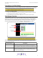
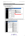
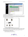
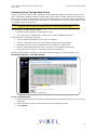
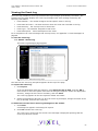
Configuring the Port Smart Settings
The Port Smart Settings page displays the current Smart Settings (configuration settings)
assigned to each port and enables users to easily create and modify custom Smart Settings.
To view the Port Smart Settings page:
Click Port > Smart Settings.
The Port Smart Settings page appears.
Expand
button
Figure 3-8: Port Smart Settings page
Expanding the optional configuration menus on the right-side of the page by clicking the
expand buttons provides additional configuration options.
Figure 3-9: Port Smart Settings page (all options displayed)
EMBEDDED IN THE FUTURE OF STORAGE
29
VIXEL INSPEED™ SAN STORAGE SWITCH MODEL 375
USER ’S GUIDE
CHAPTER 3 SWITCH MANAGEMENT
Default Smart Settings
There are several default Smart Settings available on the switch. These default Smart Settings
were defined by Fibre Channel storage experts to ensure the switch is optimally configured for
performance and stability.
The default Smart Settings cannot be modified or deleted, but these settings can be used as
templates for creating custom Smart Settings.
Note: Changing the Smart Setting of a port may affect the performance or behavior of the
system. Depending on the implementation, some Smart Settings are more appropriate
than others.
Initiator or Target
This Smart Setting is the default setting for all switch ports from the factory. This setting offers no
change protection and all settings are set to their default values. Initiators and targets can be
connected to ports that are set to this Smart Setting.
This is the recommended Smart Setting for setups with targets and initiators connected to a
single switch.
Initiator with Stealth
This Smart Setting is used when connecting a host device to the port. When a port is set to this
Smart Setting, change notifications are not sent from the initiator to other devices, but change
notifications are received by the initiator.
This Smart Setting is appropriate for embedded storage controllers and external Host Bus
Adaptors (HBAs) or servers with installed HBAs.
Target with Stealth
This Smart Setting is used when connecting embedded storage devices, like JBODs, SBODs, tape
drives, or external RAID systems (JBODs, SBODs, or tape libraries). When a port is set to this
Smart Setting, change notifications are sent to other devices, but change notifications are not
received by the target.
Fabric Connection
This Smart Setting is used when connecting a port to a Fabric switch. Only one connection from
the Vixel InSpeed™ SAN Storage Switch Model 375 to a Fabric switch is valid.
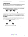
Tree Cascade
This Smart Setting is used when connecting two or more switches together in a tree
configuration. Up to four tree cascades are supported between switches. See “Cascading
Switches” on page 44 for additional information.
String Cascade
This Smart Setting is used when connecting two or more switches together in a string
configuration. Up to four string cascades are supported between two switches. See “Cascading
Switches” on page 44 for additional information.
Before selecting a cascade option, consider the following:
•
Cascade ports of like number should be connected together. For example, connect port 1
of Switch A to port 1 of Switch B, connect port 2 of Switch B to port 2 of Switch C, and so
on.
•
Cascade port numbers must be lower than non-cascade port numbers (for example,
Initiator or Target ports). Therefore, select cascade types before selecting these noncascade types.
•
A maximum of three switches may be connected using string cascades.
EMBEDDED IN THE FUTURE OF STORAGE
30
VIXEL INSPEED™ SAN STORAGE SWITCH MODEL 375
USER ’S GUIDE
•
CHAPTER 3 SWITCH MANAGEMENT
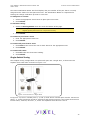
When configuring multiple switches with a single cascade, use alternating ports. For
example, connect the second switch using ports 1 and the third using ports 2 as shown in
Figure 3-10.
Figure 3-10: Alternating Ports for Single Cascades
To assign a Smart Setting to one or more ports:
1. Select the appropriate Smart Setting from the list box.
2. From the list of port numbers, select the ports that will use the selected Smart Setting
under the Assign heading.
3. Once completed, click Submit to save the settings.
To set all ports to the currently selected Smart Setting:
1. Select the desired Smart Setting from the list box.
2. Click Set All.
3. Click Submit to save the new settings.
Creating Custom Smart Settings
In addition to the default Smart Settings, users can create custom Smart Settings for use in a
specific network environment.
To create a custom Smart Setting:
1. Click Create.
A text box appears prompting for the name of the new Smart Setting.
Note: The Create function always uses the Initiator or Target Smart Setting as the
base setting from which to configure a custom Smart Setting.
2. Enter the new Smart Setting name.
A name may consist of up to 28 alphanumeric characters and cannot contain spaces (use
underscores for spaces in names).
3. Click OK.
The new Smart Setting is added to the list box.
4. Click Submit to save the new Smart Setting.
EMBEDDED IN THE FUTURE OF STORAGE
31
VIXEL INSPEED™ SAN STORAGE SWITCH MODEL 375
USER ’S GUIDE
CHAPTER 3 SWITCH MANAGEMENT
To create a custom Smart Setting based on an existing Smart Setting:
1. Select a Smart Setting from the list box that most closely matches the port settings that
the new Smart Setting should have.
2. Click Clone.
3. Enter the new Smart Setting name.
A name may consist of up to 28 alphanumeric characters and cannot contain spaces (use
underscores for spaces in names).
4. Click OK.
The new Smart Setting is added to the list box.
5. Click Submit to save the new Smart Setting.
To modify a custom Smart Setting:
1. Ensure the custom Smart Setting is not currently assigned to a port before making any
changes.
2. Select the custom Smart Setting in the list box.
3. Select the new settings.
4. Click Submit to save the new settings.
To rename a custom Smart Setting:
1. Select the desired Smart Setting from the list box.
2. Click Rename.
3. Enter the new Smart Setting name.
A name may consist of up to 28 alphanumeric characters and cannot contain spaces (use
underscores for spaces in names).
4. Click OK.
The new Smart Setting name appears in the list box.
5. Click Submit to save the change.
To delete a custom Smart Setting:
1. Ensure the custom Smart Setting is not selected or currently in use.
2. Select the custom Smart Setting in the list box.
3. Click Delete.
4. Click Submit to save the settings.
Smart Setting Assignments
The Smart Settings are based on several port settings grouped into the following categories:
•
Port Information
•
Pre-Insertion Testing
•
Change Notifications
•
Port Recovery
•
Diagnostics
These settings can be adjusted on custom Smart Settings; however, these settings are fixed on
the default Smart Settings.
EMBEDDED IN THE FUTURE OF STORAGE
32
VIXEL INSPEED™ SAN STORAGE SWITCH MODEL 375
USER ’S GUIDE
CHAPTER 3 SWITCH MANAGEMENT
Port Information
The following settings are available.
Setting
Description
Smart Setting Name
Displays the name of the Smart Setting. The Smart Setting name will
automatically appear in the text box when selected in the scroll menu.
Smart Setting Type
The topology among switches for a port. Options include:
• Initiator or Target Port – the default setting. Should be used when
there are no links between switches.
• Tree Cascade – designates the port as a tree cascade port. Use this
setting when connecting multiple switches together in a tree cascade
configuration. Under most conditions, this setting will result in
acceptable performance.
• String Cascade 1 through String Cascade 4 – designates the string
cascade to which a port is assigned. String cascades maintain fairness
when two or more InSpeed-based storage switches are serially
cascaded. Switch performance may be lower when compared to a tree
cascade configuration.
Pre-Insertion Testing
The following settings are available.
Setting
Description
Enable Policies/Smart
Insertion
This policy is the default operating mode for all ports and determines
what the switch looks for prior to allowing a port to insert into a zone.
When the policy is enabled, an external device is sent an F7
Initialization notification by the switch until an F7 Initialization
notification is received from the device. Once an F7 Initialization
notification is received, the port is inserted in the zone.
This policy takes precedence over all other policies. When this policy is
disabled, no additional policies are operational, and as long as a port
transmits a signal of the correct frequency and amplitude, the port will
be allowed in the zone.
Port Test Before Insertion
This policy ensures a device on a port is a valid, standards-compliant
participant before allowing the device to be inserted into a zone. The
device must meet all of the FC-AL requirements along with going
through a complete change notification cycle. During the change
notification cycle, the device becomes the Initialization Master (IM)
and goes through the change notification phases. Once the change
notification cycle is complete, the device can be inserted. This process
ensures a bad device is not allowed into the zone.
EMBEDDED IN THE FUTURE OF STORAGE
33
VIXEL INSPEED™ SAN STORAGE SWITCH MODEL 375
USER ’S GUIDE
CHAPTER 3 SWITCH MANAGEMENT
Change Notifications
The following settings are available.
Setting
Stealth Intelligent Change
Manager
Description
Stealth Intelligent Change Manager provides stability and control over
change notification disruptions on a port basis. Options include:
• Off: No Change Protection – no Stealth Intelligent Change Manager
control.
• Initiator: Only Receive Changes – devices attached to the port can
receive change notifications but will not propagate change notifications
generated by that port to other ports.
• Target: Only Send Changes – propagates change notifications
generated by the port to other ports but will not allow devices attached
to the port to receive change notifications from other ports.
• Switch-Switch: Send and Receive Changes – allows change
notifications to propagate between switches.
• Custom-1 – Note: This setting should not be used unless directed to do
so by a customer service representative.
Change Notification on
Insertion
The switch normally operates under the condition that when a device
is inserted onto the network, a change notification is generated.
However, this condition is not always true when connecting hubs or
switches together. In some instances, it is possible to connect two
zones together without the zones realizing that multiple AL_PAs exist
with the same values.
When this policy is enabled, the switch always generates a change
notification to ensure the proper system updates are performed.
However, when a device is removed (for example, an initiator or
target), the removal does not generate a change notification and there
are no system updates performed.
Change Notification on
Removal
This policy is similar to the Change Notification on Insertion policy,
except for the change notification being sent when a device is
removed rather than inserted.
When this policy is enabled, the switch always generates a change
notification to ensure the proper system updates are performed.
Port Recovery
The following settings are available.
Setting
Bad Device Recovery
Description
When a port is already inserted into a zone, the port transforms F8
Failure notifications into F7 Initialization notifications. When this
occurs, the port is bypassed and F7 Initialization notifications are
allowed in the zone. Once the initialization is complete, the Bad Zone
Recovery Policy is operational and prevents a port that continues to
transmit F8 Failure notifications from inserting into the zone.
Note: If this policy is disabled while the Bad Zone Recovery policy is
enabled, a zone that does go down will still allow the Bad Zone Recovery
policy to reset the zone and allow ports to be reinserted.
When enabled, this policy prevents devices that send F8 Failure
notifications from inserting into a zone. The ability to remove devices
that generate F8 Failure notifications automatically and
instantaneously guarantees continual system operation.
When disabled, this policy allows devices that send F8 Failure
notifications to insert into a zone and does not consider F8 Failure
notifications when determining whether to insert a device or not.
EMBEDDED IN THE FUTURE OF STORAGE
34
VIXEL INSPEED™ SAN STORAGE SWITCH MODEL 375
USER ’S GUIDE
Setting
CHAPTER 3 SWITCH MANAGEMENT
Description
Clear on Stall
In situations where the switch is operating in switching mode, some
devices may fall into an operating mode where the device has opened
a target but has not released the connection to the target. When this
policy is enabled, the switch can detect this condition and
automatically recover when this situation arises.
Bypass on No Activity
The switch detects the amount of time a data stream has gone
without receiving a comma. The time setting is set to 100 (.001
seconds). When this policy is enabled, the switch bypasses the
disruptive port when the threshold is exceeded.
Bypass on Ordered Set Error
Ordered Set (OS) errors are detected and counted for each individual
port. When this policy is enabled, a port is bypassed when its OS
count exceeds the threshold setting. The threshold setting is based on
the number of ordered set errors identified in 10 seconds.
Note: This threshold setting can be adjusted on the Web Manager’s
Advanced Functions Switch Thresholds page.
Bypass on CRC Error
Cyclic Redundancy Check (CRC) errors are detected and counted for
each individual port. When this policy is enabled, a port is bypassed
when its CRC count exceeds the threshold setting. The threshold
setting is based on the number of CRC errors identified in 10 seconds.
User intervention is required to return the port into the zone.
Recovery methods include replacing the defective component, cycling
power to the device on the port, removing and reinserting the
bypassed port, or cycling power to the switch.
Note: This threshold setting can be adjusted on the Web Manager’s
Advanced Functions Switch Thresholds page.
Diagnostics
The following settings are available.
Setting
Port Control
Description
The method for controlling a port. Options include:
• auto – the default setting. The switch will automatically insert a port
based on policy settings. This prevents the insertion of incompatible
ports, which may cause disruption.
• bypass – removes a port from the network. Use this mode to keep a
device out of an initialization cycle when troubleshooting.
• extLoopback – removes a port from the network and routes the
port's receive signal back through the port's transmitter. Use this
mode to isolate a specific zone for troubleshooting or to test a
transceiver’s circuitry and attached media from the node end.
• insert – allows ports whose transceivers cannot derive a valid clock
or "K" character (Ordered Set) to join a zone. Use this mode
cautiously – devices without valid characters may put bad data into
a zone, causing the zone to go down.
Bypass on Clock Delta
The switch determines the relative frequency of the signal being
received by a port to the internal switch clock. The result of this
test allows the determination of how far apart in frequency the
switch’s clock is in relation to the clock of the received signal – the
clock delta. If the clock delta exceeds a set threshold, the switch is
notified and the port may be bypassed if necessary. Typically, clock
drift is slow enough to allow the removal and replacement of a
defective part before the defective part begins to affect system
performance.
EMBEDDED IN THE FUTURE OF STORAGE
35
VIXEL INSPEED™ SAN STORAGE SWITCH MODEL 375
USER ’S GUIDE
CHAPTER 3 SWITCH MANAGEMENT
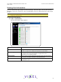
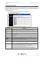
Managing Firmware and Configuration Files
The Switch Files page displays information on the switch’s firmware and configuration files.
To view the firmware and configuration files, click Switch > Files.
The Switch Files page appears.
Figure 3-11: Switch Files page
Switch Firmware Files
This section displays the current and alternate firmware versions, enables users to select which
firmware version to run the next time the switch is reset, and provides a means to load new
firmware on the switch.
To view or download the latest switch firmware, click Help > Downloads. The Web Manager will
display the firmware request page. Enter the requested customer information and an email with
the location of the appropriate firmware download page for the switch will be sent to the specified
email address. If necessary, download the latest switch firmware to the host system.
To load new firmware on the switch:
1. Under Download New Alternate Firmware Version to Switch, enter the directory path and
the specific file name in the text box, or click Browse to navigate to and select the
appropriate file on the host system. The file must have a .bin extension.
2. Click Start to load the new firmware image.
Once the firmware has been installed, the new firmware should appear as the Alternate
Version firmware.
3. Under Next Boot Firmware Version, ensure the Use Alternate Version on Next Reboot
option is selected. The alternate firmware version currently displayed will be loaded on the
next boot cycle.
4. Click Reboot to reset the switch using the selected firmware.
Note: When loading new firmware on the switch, clear the web browser’s cache and files to
ensure the removal of the older firmware information. In Internet Explorer, use the key
combination C TRL +F5, or select Tools > Internet Options and click Delete Files.
EMBEDDED IN THE FUTURE OF STORAGE
36
VIXEL INSPEED™ SAN STORAGE SWITCH MODEL 375
USER ’S GUIDE
CHAPTER 3 SWITCH MANAGEMENT
To select the alternate firmware version for the next boot:
1. Under Next Boot Firmware Version, select Use Alternate Version on Next Reboot. The
alternate firmware version currently displayed will be loaded on the next boot cycle.
2. Click Submit.
3. Click Reboot to reset the switch.
Switch Configuration Files
Switch configuration settings (for example, zoning or Port Smart Settings) can be saved for
backup purposes or for loading the same configuration on multiple switches.
To save the current configuration:
1. Click Save to save the current switch configuration.
2. Click OK on the File Download dialog box.
3. Enter the directory path and file name, being sure to use a .cfg extension.
4. Click Save.
To load a saved configuration:
1. Under Download New Configuration File to Switch and Reboot, enter the directory path to
the .cfg file in the text box, or use the Browse button to navigate to the appropriate file.
2. In the Choose File dialog box, navigate to and select the appropriate file and click OK.
3. Click Start.
A message box appears confirming the download and required switch reset.
4. Click OK to proceed.
Restoring the Factory Default Settings
If necessary, the switch settings can be reset to their factory default values; however, the
network configuration and port type settings are retained.
To restore the factory default configuration:
1. From the Restore Configuration to Factory Default section, click Restore.
A message box appears confirming the request.
2. Click OK to restore the factory default configuration and reset the switch.
EMBEDDED IN THE FUTURE OF STORAGE
37
VIXEL INSPEED™ SAN STORAGE SWITCH MODEL 375
USER ’S GUIDE
CHAPTER 3 SWITCH MANAGEMENT
One-Step Zoning
Zoning allows ports to be divided into multiple virtual zones (or work groups), similar to Virtual
Local Area Networking (VLAN). By separating activity on the network, zoning also eliminates
change notification propagation (change notifications that occur within one zone cannot
propagate to other zones.)
Use zoning to:
•
•
•
•
Separate different operating system environments.
Temporarily block or grant access during backup or other tasks.
Consolidate equipment logically.
Designate closed user groups for increased security.
•
Separate test or maintenance areas from production areas.
Zone configuration settings are available on the Web Manager’s One-Step Zoning page. The page
is arranged as a grid of check boxes for placing ports in appropriate zones. Ports are listed across
the top of the grid. Zones are listed down the left side. Similar to other Web Manager pages, the
port color represents the current port status.
To view the One-Step Zoning page:
Click Advanced Functions > One-Step Zoning.
Figure 3-12: One-Step Zoning page
The switch is capable of up to twelve zones. Initially, all ports reside in Zone 0. However, a port
will clear from Zone 0 whenever it is selected and placed in another zone.
The color of each zone indicates its status. See the descriptions in the following table:
Color
Description
Down (red)
One or more ports have been selected, zoning has been activated, but
hardware has caused a failure.
Up (green)
Ports have been selected, zoning has been activated, and the FC-AL
circuit is operational.
Not Active (yellow)
Ports have been selected but zoning has not been activated.
Undefined (gray)
No ports have been selected.
EMBEDDED IN THE FUTURE OF STORAGE
38
VIXEL INSPEED™ SAN STORAGE SWITCH MODEL 375
USER ’S GUIDE
CHAPTER 3 SWITCH MANAGEMENT
The Zone Initialization Master Port field displays the port number of the port that is currently
assigned as the master for that particular zone. The Initialization Master is responsible for
starting the change notification process in each zone.
To add ports to a zone:
1. Select the appropriate check boxes to place ports into zones.
2. Click Submit.
To activate zoning:
1. Select the Zoning Active check box near the bottom of the page.
Caution: Clearing the Zoning Active check box will deactivate all zones, which may
degrade system performance or compromise security.
2. Click Submit.
To remove a port from a zone:
1. Clear the appropriate check box.
2. Click Submit.
To remove all ports from a zone:
1. Click Clear at the end of the row of check boxes for the appropriate zone.
2. Click Submit.
To remove all zones:
1. Click All under the Clear Zone heading.
2. Click Submit.
Single-Switch Zoning
The simplest zoning configuration is to place each port into a single zone, so that zones are
separate from each other as shown in Figure 3-13.
Figure 3-13: Devices in a Single Zone
In Figure 3-13, zone 1 includes ports 1, 3, and 4, while zone 2 includes ports 2 and 5. Devices on
ports 1, 3, and 4 have direct access to each other and devices on ports 2 and 5 have direct access
to each other; however, devices 1, 3, and 4 are separated from devices 2 and 5.
EMBEDDED IN THE FUTURE OF STORAGE
39
VIXEL INSPEED™ SAN STORAGE SWITCH MODEL 375
USER ’S GUIDE
CHAPTER 3 SWITCH MANAGEMENT
Figure 3-14: Single switch zoning configuration
Adding Devices to Multiple Zones
In the previous example, each host only communicates with the devices in the same zone as the
host. However, there may be situations in which hosts in separate zones need to share devices.
When this situation occurs, use overlapping zones to share the devices between the hosts. Figure
3-15 depicts this type of zoning configuration.
Figure 3-15: Devices in Multiple Zones
In Figure 3-15, zone 1 includes ports 1, 3, and 4, while zone 2 includes ports 2, 4 and 5. Port 4 is
in both zones. Devices on ports 1, 3, and 4 have direct access to each other and devices on ports
2, 4, and 5 have direct access to each other, but devices 1 and 3 are separated from devices 2
and 5. The device on port 4 has direct access to all the devices on ports 1, 2, 3, and 5.
To add storage devices to multiple zones:
1. Select the appropriate zones for each port.
2. Ensure the Zoning Active check box is selected.
EMBEDDED IN THE FUTURE OF STORAGE
40
VIXEL INSPEED™ SAN STORAGE SWITCH MODEL 375
USER ’S GUIDE
CHAPTER 3 SWITCH MANAGEMENT
3. Click Submit.
Figure 3-16: Ports in Multiple Zones on the One-Step Zoning page
Multiple Switch Zoning
Zones can be configured across multiple switches using a similar procedure to a single switch.
However, multiple-switch zoning requires some coordination between the switches. Building on
the example for ports in multiple zones, move the devices onto two switches and have the zones
stretch between the two, as in Figure 3-17.
Figure 3-17: Devices in Multiple Zones Across Multiple Switches
In Figure 3-17, zone 1 includes ports 2, 4, 5, and cascade port 1, while zone 2 includes ports 3, 5,
6, and cascade port 1. Ports 1 (cascade port) and 5 are in both zones.
EMBEDDED IN THE FUTURE OF STORAGE
41
VIXEL INSPEED™ SAN STORAGE SWITCH MODEL 375
USER ’S GUIDE
CHAPTER 3 SWITCH MANAGEMENT
To configure multiple-switch zoning, do the following for each switch:
1. Plan which ports should belong in each zone.
2. From the One-Step Zoning page, select the appropriate ports for each zone.
Switch B
Switch A
Figure 3-18: Zones Coordinated on Multiple Switches
3. Ensure the Zoning Active check box is selected for both switches.
Caution: Clearing the Zoning Active check box will deactivate all zones, which may
degrade system performance or compromise security.
4. After making changes, click Submit.
AL_PA Zoning
Another zoning configuration is AL_PA zoning, which enables users to specify that certain devices
only communicate with one another. AL_PA zoning is only accessible through the Command Line
Interface (CLI). Refer to the InSpeed Storage Switch CLI Reference Guide for additional
information.
Recovering a Bad Zone Automatically
Bad zone recovery policy automatically recovers traffic if a device has brought down the zone. The
zone state is monitored continuously. If ports are inserted into a zone, but the zone state never
transitions to the Zone Up or Zone Active state after a set period of time (Hold Time), all devices
in the pertinent zone are bypassed and then allowed to reinsert. There is a secondary timeout,
the Bad Zone Recovery Delay Time, that can also be configured. The Bad Zone Recovery Delay
Time causes a delay before ports are allowed to reinsert, which prevents a high "thrashing" level
of port insertions and de-insertions and ensures that some devices can reset. The Bad Zone
Recovery Hold Time and Delay Time threshold settings are available on the Advanced Functions
Switch Thresholds page.
When this policy is enabled with the associated PTBI policy, the device causing a zone to go down
is not allowed back into the zone due to the PTBI policy, which allows the system to return to
normal operation. The combination of the Bad Zone Recovery and PTBI policies has resulted in
significant improvements to SAN availability.
Note: The Bad Zone Recovery policy is enabled by default. If the Bad Zone Recovery policy is
disabled, use the following instructions to enable this policy for the appropriate zones.
To activate bad zone recovery:
1. Click Advanced Functions > One-Step Zoning.
2. Under Bad Zone Recovery, select the check boxes for the appropriate zones.
3. Click Submit.
EMBEDDED IN THE FUTURE OF STORAGE
42
VIXEL INSPEED™ SAN STORAGE SWITCH MODEL 375
USER ’S GUIDE
CHAPTER 3 SWITCH MANAGEMENT
Connecting Ports Through Hard Zoning
A Hard Zone can be used to add a separate 126 AL_PAs that operate in isolation from any other
zone. A Hard Zone disables switching functionality and creates a shared connection between the
ports in a zone topology, splitting the switch into multiple unique FC-AL zones. When Hard Zoning
is enabled, all switch zones must be Hard Zones. A combination of Hard Zones and regular zones
on a single switch is not allowed.
Caution: Do not set a Hard Zone for ports in multiple zones or share ports that have the Hard Zone
option set. This will cause errors that do not log an event or display a message.
The advantages of Hard Zoning include:
•
Each Hard Zone contains 126 available AL_PAs.
•
The switch can be configured to contain up to eleven isolated Hard Zones.
The limitations of Hard Zoning include:
•
2 Gb of shared bandwidth over the entire Hard Zone.
•
Ports in a Hard Zone cannot use the Stealth Intelligent Change Manager.
•
Automatic Trunking and route blocking are not allowed in a Hard Zone.
•
Ports in a Hard Zone cannot be set to a string or tree cascade configuration.
•
Device AL_PAs on a port in a Hard Zone cannot be displayed.
The Hard Zone setting is available on the One-Step Zoning page. To view the page, click
Advanced Functions > One-Step Zoning.
Figure 3-19: Hard Zoning configuration
To set up Hard Zoning:
1. Determine which ports will reside in each Hard Zone and ensure the ports are in only one
Hard Zone.
2. Under Hard Zone, select the check boxes for the appropriate zones.
3. Click Submit.
EMBEDDED IN THE FUTURE OF STORAGE
43
VIXEL INSPEED™ SAN STORAGE SWITCH MODEL 375
USER ’S GUIDE
CHAPTER 3 SWITCH MANAGEMENT
Cascading Switches
When multiple switches are connected, the connecting links between the switches are referred to
as "cascades". There are two distinct cascade configurations to consider when configuring
networks for optimal performance and connectivity: string cascades and tree cascades.
String Cascades
A string cascade connects multiple switches (up to three switches maximum) together in a "daisychained" configuration. When one device requests access to another device, the request is sent to
each switch in the cascade before device access is granted. This arbitration method promotes
fairness between the switches. However, when compared to tree cascades, string cascades offer
less performance due to the increased latency between the switches.
Figure 3-20: String Cascade configuration example
When configuring a switch port for a string cascade, use the String Cascade Smart Setting. To
reduce contention and improve performance between initiator traffic and target traffic when using
a string cascade configuration, connect the ports of each switch together using the same String
Cascade Smart Settings. For example, in Figure 3-20 the three switches are connected through
two string cascades using the String Cascade - Trunk 1 and String Cascade - Trunk 2 Smart
Settings. This creates two dedicated paths through which initiators and targets can communicate.
Tree Cascades
Tree cascades provide the best performance (lowest latency) configuration. A tree cascade
consists of a root switch connected to additional switches (up to 8 switches maximum). When a
device on a switch requests access to another device, the request is sent the particular switch for
that device. The limitation to the tree cascade configuration is the random nature of devices
gaining access to one another, as fairness is not used for tree cascades.
Figure 3-21: Tree Cascade configuration example
When configuring a port for a tree cascade, use the Tree Cascade Smart Setting.
EMBEDDED IN THE FUTURE OF STORAGE
44
VIXEL INSPEED™ SAN STORAGE SWITCH MODEL 375
USER ’S GUIDE
CHAPTER 3 SWITCH MANAGEMENT
Automatic Trunking
Multiple links between switches are called “trunks”. Trunks provide higher bandwidth across
cascaded switches for systems incorporating multiple initiators. Each trunk can improve system
throughput and provide “failover” capability. A maximum of 4 trunks between each switch is
supported. Trunking is performed automatically when ports are configured properly. Figure 3-22 is
an example of Automatic Trunking.
Figure 3-22: Automatic Trunking example
Each trunk is part of a trunk group. A trunk group consists of two or more cascades between two
switches. There can only be one trunk group between two switches. Each trunk group contains a
primary trunk. All traffic flows through the primary trunk on a switch unless specified otherwise
using the Load Balancing feature. The primary trunk is always the lowest numbered port of any
trunk group.
If the primary trunk fails, the secondary trunk automatically becomes the primary trunk unless
otherwise configured. Multiple cascades also enable switch configuration for better performance
through load balancing (see “Load Balancing” on page 46).
The Automatic Trunking page enables users to configure trunking by defining trunk groups and
assigning ports to those groups. The Automatic Trunking feature is available when one or more
ports are assigned a String or Tree Cascade Smart Setting.
To configure Automatic Trunking:
1. Click Advanced Functions > Automatic Trunking.
The Automatic Trunking page appears.
Figure 3-23: Advanced Functions: Automatic Trunking page
2. Select a trunk group for each port by clicking the appropriate Trunk Group option.
3. When finished making changes, click Submit.
EMBEDDED IN THE FUTURE OF STORAGE
45
VIXEL INSPEED™ SAN STORAGE SWITCH MODEL 375
USER ’S GUIDE
CHAPTER 3 SWITCH MANAGEMENT
Load Balancing
Load balancing builds on the Automatic Trunking functionality by specifying the path that the data
uses to flow between multiple switches. Users can manage the switch’s aggregate bandwidth by
manually distributing traffic across multiple cascade ports as shown below. A cascade port is a
port that is attached to another switch of the same type and configured as a String or Tree
Cascade Smart Setting on the Port Smart Settings page. All data flows through the primary
cascade, unless the switch is configured differently.
Note: Cascade ports must be properly configured before load balancing will work.
Figure 3-24: Load Balancing Across Multiple Cascade Ports
In Figure 3-24, host 1 uses cascade port 1, while host 2 uses cascade port 2. All traffic will use
the lowest numbered (primary) cascade port by default but ports may be configured to use other
cascades.
Note: When tape drives or tape libraries are included in multiple switch configurations
incorporating multiple trunks, place the tape drive or tape library and any devices that
access those devices on the secondary (duplicate) trunk, not the primary trunk.
Load balancing configuration settings are available on the Web Manager’s Load Balancing page.
Before implementing load balancing on the switch, the automatic trunking settings must be
configured. See “Automatic Trunking” on page 45 for additional information.
To view the Load Balancing page:
Click Advanced Functions > Load Balancing.
EMBEDDED IN THE FUTURE OF STORAGE
46
VIXEL INSPEED™ SAN STORAGE SWITCH MODEL 375
USER ’S GUIDE
CHAPTER 3 SWITCH MANAGEMENT
Figure 3-25: Load Balancing page
The page is arranged as a grid of check boxes for assigning ports to cascades ("Trunk Groups").
Load Indicators
The Load Balancing page incorporates two sets of visual indicators for measuring traffic:
•
Port Load Indicators–the horizontal bars on the right side of the page that display the
current load for each port.
•
Trunk Load Indicators–the vertical bars at the bottom of the page that display the current
load for each trunk group.
These bars indicate the amount of traffic across a trunk or port. The size of the bars increase in
correlation to the amount of traffic and, as a bar’s size increases, can identify a specific trunk or
port that is overloaded. If overloading occurs, move one or more ports to a different trunk in the
group.
To change the load balancing settings:
1. Click a Trunk Group option to place a port into a specific trunk group.
2. Continue to assign ports to trunk groups as necessary.
3. When finished, click Submit.
Fairness and Prioritization
The concept of "fairness" is based on the principle of ensuring fair device access and
communication across all devices in a storage system. The switch incorporates fairness and
prioritization through Vixel’s InSpeed technology and Automatic Trunking and Load Balancing
functionality. In cooperation with each other, these features ensure even and equal access
through multiple links fairly–effectively multiplying bandwidth.
Device prioritization can be achieved using Load Balancing and assigning only a specific device
port to a particular cascade. This ensures a specific device will always have a dedicated trunk.
EMBEDDED IN THE FUTURE OF STORAGE
47
VIXEL INSPEED™ SAN STORAGE SWITCH MODEL 375
USER ’S GUIDE
MONITORING
THE
CHAPTER 3 SWITCH MANAGEMENT
S WITCH
The Vixel InSpeed™ SAN Storage Switch Model 375 provides several options for monitoring the
switch status and port information. This section describes how to view switch status, the event
log, port information and utilization, and port diagnostics.
Viewing Switch Status
The Web Manager’s home page is the Switch Information page. This page is displayed first when
the Web Manager is opened and shows general switch information, including switch status, fan
and power supply operational indicators, and port health and utilization.
This page continually refreshes to guarantee that the most current switch status is displayed. To
return to this page at any time, click the InSpeed™ Storage Switch menu item.
Figure 3-26: Switch Information page
Switch Information
Current status is provided for the following items.
Item
Status Indicators
Switch Status
OK (green)–the switch unit is operating normally.
Fault (red)–one or more of the ports has failed, the internal temperature
has exceeded acceptable levels, or another error has occurred. Errors
appear in the event log. The switch will continue to operate; however,
functionality may be impaired depending on the event that triggered the
error. Regardless of the cause, the switch requires immediate attention.
InSpeed SOC Status
OK (green)–the switch chipset is operating normally.
Fault (red)–the switch chipset’s selftest has failed.
Enclosure Temperature
OK (green)–the switch temperature is within the normal operating range.
OverTemp (red)–the enclosure temperature has exceeded the
recommended operating range.
Fan #1
OK (green)–the fan unit is working properly.
Not Present (yellow)–the power supply/fan module has been removed.
Fault (red)–the fan unit has stopped operating. Verify that the power
supply/fan module is properly seated in the switch.
Fan #2
OK (green)–the fan unit is working properly.
Not Present (yellow)–the power supply/fan module has been removed.
Fault (red)–the fan unit has stopped operating. Verify that the power
supply/fan module is properly seated in the switch.
EMBEDDED IN THE FUTURE OF STORAGE
48
VIXEL INSPEED™ SAN STORAGE SWITCH MODEL 375
USER ’S GUIDE
Item
CHAPTER 3 SWITCH MANAGEMENT
Status Indicators
Power Supply #1
OK (green)–the power supply unit is working properly.
Not Present (yellow)–the power supply/fan module has been removed.
Fault (red)–the power supply unit has stopped operating. Verify that the
power supply/fan module is properly seated in the switch.
Power Supply #2
OK (green)–the power supply unit is working properly.
Not Present (yellow)–the power supply/fan module has been removed.
Fault (red)–the power supply unit has stopped operating. Verify that the
power supply/fan module is properly seated in the switch.
Port Utilization and Health
Port utilization measures the amount of traffic passing into a port over a period of time. For
example, if an initiator is transmitting data to a target, the initiator port displays a port utilization
value (%) while the target port does not. If the same initiator is receiving data from the target,
the target port displays a port utilization value (%) while the initiator port displays does not.
This part of the web page displays each port number, the port’s current health status, and a
vertical bar indicating the port utilization.
Tip: Rolling the mouse cursor over the port number displays the current port state.
A port number is displayed in one of three colors depending on the port’s current health:
Port Color
Indication
Green
An SFP is inserted into the port and a device is connected to the SFP.
Yellow
Bypassed – The port is bypassed. An SFP may be inserted in the port but there
may not be a device connected to the SFP.
Loopback – There is no device connected to the port. The transmit and
receiver are connected together on the SFP transceiver.
LIPF8Present – If the switch is receiving an F8 Failure notification, the port is
bypassed to allow remaining devices to proceed with initialization.
Redundant – The port is a failover link in a cascade and is not currently active.
Red
TxFault – Detects an SFP transmitter fault.
DiagTx – Detects Ordered Sets being transmitted, so traffic cannot be passed
through the port.
DataTimeout – Detects a data timeout fault.
RxLoss – Detects a loss of received signal amplitude from the device.
SyncLoss – Detects a loss of word synchronization for a specified time, which
may be caused by poor signal strength, intermittent line conditions, etc.
Gray
Unknown – The port status cannot be determined.
NoSFP – There is no SFP connector inserted in the port.
Port utilization is measured by a vertical bar that moves upwards as utilization increases. The
vertical bar has the three distinct levels of utilization:
Bar Color
Indication
Green
The port is operating at optimal utilization.
Yellow
The port is experiencing periods of heavy traffic.
Red
The port has too much traffic on it and is not operating at desired levels. Some
devices should be transferred to other ports to improve port utilization.
EMBEDDED IN THE FUTURE OF STORAGE
49
VIXEL INSPEED™ SAN STORAGE SWITCH MODEL 375
USER ’S GUIDE
CHAPTER 3 SWITCH MANAGEMENT
Viewing the Event Log
The Event Log contains a list of up to 3000 event log messages generated by the switch. The
Switch Event Log page displays the event log messages with each message containing the
following information:
•
Event Number – the number assigned to that specific event in the log.
•
Event Date and Time – the date and time when the event was recorded in the log.
•
Event Severity – the severity level for that event.
•
Event Type – the identifier assigned to that event.
•
Event Description – a brief description of the event.
For a complete list of event messages and severity levels, see Appendix C: Event Messages on
page 66.
To view the event log:
Click Switch > Event Log.
The Event Log Messages page appears.
Figure 3-27: Switch Event Log page
The last time the event log was polled appears at the top of the page.
To export the event log:
1. Click Export.
If the File Download dialog box appears, select Save this file to disk, and click OK to
save the file on the host system. The Save As dialog box appears. Select the appropriate
directory, change the file name if necessary, and click Save.
The event log appears in the host system’s default text editor.
2. Select the appropriate directory to save the event log messages, change the name of the
file (if desired), and save the event log.
To delete the current list of event log messages on the switch:
1. Click Clear.
A message box appears confirming the request.
2. Click OK to delete the event log.
The event log is cleared out and a new event message is displayed reporting that the
event log has been cleared.
EMBEDDED IN THE FUTURE OF STORAGE
50
VIXEL INSPEED™ SAN STORAGE SWITCH MODEL 375
USER ’S GUIDE
CHAPTER 3 SWITCH MANAGEMENT
Viewing Port Information
The Port Information page displays the Smart Settings, Serial ID (SID), and AL_PAs currently
assigned to each port. Initiator AL_PAs are highlighted in blue to differentiate them from target
AL_PAs.
Note: The Initiator AL_PA information can be used to easily identify attached devices when
configuring load balancing.
To view port information:
Click Port > Information.
The Port Information page appears.
Figure 3-28: Port Information page
Field
Description
Port
Displays the current health of the port. See “Port Utilization and
Health” on page 45 for additional information on port health.
Smart Setting
Displays the specific Smart Setting assigned to a particular port. See
“Configuring the Port Smart Settings” on page 29 for more
information on the Smart Settings.
Serial ID (SID)
When clicked, provides additional information about the SFP inserted
in the port, if an SFP is inserted in that particular port.
Identified ALPAs
Displays all the AL_PAs attached to the port. Initiator AL_PAs appear
highlighted in blue.
EMBEDDED IN THE FUTURE OF STORAGE
51
VIXEL INSPEED™ SAN STORAGE SWITCH MODEL 375
USER ’S GUIDE
CHAPTER 3 SWITCH MANAGEMENT
Viewing Port Utilization
Port utilization measures the amount of traffic passing through a port over a period of time. For
example, if an initiator is transmitting data to a target, the initiator port displays a port utilization
value (%) while the target port does not. If the same initiator is receiving data from the target,
the target port displays a port utilization value (%) while the initiator port displays does not.
The Port Utilization page displays each port’s utilization percentage based on high, average, and
low utilization.
Value
Description
High
The highest percentage of data communication through a port over a period of
time (measured in seconds).
Average
The average percentage of data communication through a port over a period
of time (measured in seconds).
Low
The lowest percentage of data communication through a port over a period of
time (measured in seconds).
To change the port utilization interval:
Click Advanced Functions > Thresholds > Switch. See “Adjusting the Switch Thresholds”
on page 28 for additional information.
To view port utilization:
Click Port > Utilization.
The Port Utilization page appears.
Figure 3-29: Port Utilization page
EMBEDDED IN THE FUTURE OF STORAGE
52
VIXEL INSPEED™ SAN STORAGE SWITCH MODEL 375
USER ’S GUIDE
CHAPTER 3 SWITCH MANAGEMENT
Viewing Port Diagnostics
This page displays diagnostic information pertaining to each port in the switch. Use the
information provided on this page to diagnose abnormally high error counts on a particular port.
To view the current diagnostic settings:
Click Advanced Functions > Diagnostics > Port.
The Port Diagnostics page appears.
Figure 3-30: Port Diagnostics page
Statistic
Port & Health
Description
Color Indicators
• Green
• Yellow
• Red
See “Port Utilization and Health” on page 49 for descriptions of the health
indicators.
Insertion Count
Number of times this port has been inserted into the network since the switch
was reset or the counters were cleared.
CRC Errors
Number of CRC errors that are detected in frames passing through this port
since the switch was reset or the counters were cleared.
Ordered Set Errors
Number of Ordered Sets that are received on this port with an encoding error
since the switch was reset or the counters were cleared.
Clock Delta
Difference (in parts per million) between the internal switch clock and the
received clock signal on the port.
State
Current state of this port – either inserted or bypassed
Beacon Port
Forces both port LEDs to flash on and off continuously. Use this to locate and
take action on a specific port. The flashing overrides normal port indication
until beaconing is turned off; however, port operation continues to operate
normally.
EMBEDDED IN THE FUTURE OF STORAGE
53
VIXEL INSPEED™ SAN STORAGE SWITCH MODEL 375
USER ’S GUIDE
Statistic
CHAPTER 3 SWITCH MANAGEMENT
Description
Bypass Port
A single instance operation that forces a port into bypass mode. This feature
may be used to diagnose device problems when a device is locked up or
experiencing a high number of failures on a port.
Reset Port
A single instance operation that places a port in bypass mode and then
immediately sets the port to auto-detect to re-insert the port. This feature
may be used to diagnose device problems when a device is locked up or
experiencing a high number of failures on a port.
To save diagnostic information:
1. Click Upload to save the current diagnostics to the host system.
2. Click OK on the File Download dialog box.
3. Enter the directory path and file name.
4. Click Save.
To clear the counters:
Click Clear.
Manual Port Operation
If necessary, a port can be placed into manual bypass mode or reset. If the port is placed in
bypass mode, the port will remain in bypass mode until the switch is reset. If the port is manually
reset, the port is temporarily placed in bypassed mode and then reset to re-insert the port. These
features may be used to diagnose device problems when a device is locked up or experiencing a
high number of failures on a port.
To place a port into bypassed mode:
1. Click Advanced Functions > Diagnostics > Port.
2. Select the Bypass Port option for the appropriate port.
3. Click Submit.
To reset a port:
1. Click Advanced Functions > Diagnostics > Port.
2. Select the Reset Port option for the appropriate port.
3. Click Submit.
EMBEDDED IN THE FUTURE OF STORAGE
54
VIXEL INSPEED™ SAN STORAGE SWITCH MODEL 375
USER ’S GUIDE
CHAPTER 3 SWITCH MANAGEMENT
Viewing Ordered Sets
This page displays the Ordered Sets that are being transmitted on the switch for each port since
the last time the page was displayed. Ordered Sets are used when communicating data across
networks to indicate actions, events, or status regarding the data. A list of detected Ordered Sets
and their indications is provided below.
To view ordered sets:
1. Click Advanced Functions > Diagnostics > Ordered Sets.
The Ordered Sets page appears.
Figure 3-31: Advanced Functions: Ordered Sets page
Detection
Indication
End of Frame
(EOF)
An End-of-Frame (EOF) delimiter has been detected; frames are present. (An EOF
immediately follows the CRC of a frame and signals the frame’s end.)
Start of Frame
(SOF)
A Start-of-Frame (SOF) delimiter has been detected; frames are present.
Idle
Sequences of IDLEs are being transmitted to maintain link activity; no other data
is being transmitted.
ARB(FF)
ARB(FF)s are being transmitted to maintain link activity; no other data is being
transmitted.
ARB
A port is arbitrating for network access to perform a task.
Read Ready
(RRDY)
The receiving node on this port has sent an R_RDY signal, indicating that it is
ready for a frame to be transmitted over the link.
Close (CLS)
The port is attempting to begin the process of closing the current FC-AL circuit.
Open (OPN)
The port is attempting to open communications with another port.
Note: As is the case with some ordered sets, an OPN may not go all the way
around the FC-AL, instead stopping at its destination.
F8 Failure
A non-switching port has detected a failure on its receive input, is notifying other
ports, and is determining whether the network is still operational.
Some events that could cause the port to detect network failure follow:
• A device has failed or has been powered off.
• The physical connection between the transmitter and receiver is broken.
• Activating the port bypass circuit does not typically result in a network failure.
EMBEDDED IN THE FUTURE OF STORAGE
55
VIXEL INSPEED™ SAN STORAGE SWITCH MODEL 375
USER ’S GUIDE
Detection
CHAPTER 3 SWITCH MANAGEMENT
Indication
F7 Initialization
A port is in the non-participating mode and is attempting to win arbitration and
begin initialization, possibly because the port was reset or is powering up.
Sometimes the port is sending this sequence to another hot-cascaded switch, like
a new initiator being inserted in the network.
Change
Notification
A change notification has been detected and action has been taken.
Unknown
The switch cannot determine what is being transmitted.
Invalid
An invalid transmit word has been detected.
CRC Error
A Frame CRC error has been detected.
Point-to-Point
A point-to-point connection has been detected.
EMBEDDED IN THE FUTURE OF STORAGE
56
VIXEL INSPEED™ SAN STORAGE SWITCH MODEL 375
USER ’S GUIDE
CHAPTER 4 TECHNICAL REFERENCE
C HAPTER 4 T ECHNICAL R EFERENCE
Troubleshooting Device Connections ............. 57
Troubleshooting Management Connections .... 58
Port Bypass Conditions and Recovery ........... 58
Default Smart Setting Attributes .................. 59
Fibre Channel References ........................... 60
T ROUBLESHOOTING DEVICE C ONNECTIONS
Problem
Recommended Action
SFP installed in one or
more ports but no
LEDs lit
1) Verify that the power cord is firmly seated into switch and is connected to
a properly earthed receptacle (outlet).
2) Check the Power LED to ensure that the switch is turned on.
3) Verify that the SFP is firmly seated.
SFP installed but only
yellow LED is lit
Reseat the SFP. If the same condition occurs, the SFP is probably faulty and
should be replaced.
SFP installed with both
green and yellow LEDs
lit
1) Make sure that the device is powered on and operating properly.
2) Unplug the fiber cable from the node and verify that an optical signal is
present on the cable receiver lead.
3) Verify that the fiber cable is fully seated at either end.
If optical power meter is available, verify the device is transmitting a signal.
If there is no signal present, the device may require rebooting, device
drivers may need to be reinstalled, or the HBA or disk controller hardware
may require servicing.
If a signal is present on both the cable lead and the end node, the HBA or
disk controller may require service.
4) Ensure the device and switch are operational and set to the same speed.
SFP installed with only
green LED lit, but
devices are not
communicating
The switch is receiving a valid signal from the device, but no upper level
protocols are active.
1) Verify that the proper HBA device drivers are loaded for the appropriate
operating system and that the host has been configured to recognize
attached disk devices.
2) Improper FC-AL initialization could result from a defective or inoperative
adapter card or device. Run adapter diagnostics with a loopback connector
to see if the adapter is working properly.
3) Unplug the fiber cable from the end node and verify that an optical signal
is present on the cable receiver lead. If no signal is present, the cable’s
receiver lead may be bad and the device may be streaming F8 Failure
notifications.
EMBEDDED IN THE FUTURE OF STORAGE
57
VIXEL INSPEED™ SAN STORAGE SWITCH MODEL 375
USER ’S GUIDE
CHAPTER 4 TECHNICAL REFERENCE
T ROUBLESHOOTING MANAGEMENT C ONNECTIONS
Problem
Recommended Action
Serial cable installed
but connection does
not appear on terminal
1) Cycle power by reinstalling the power cord.
2) Check the terminal emulation program’s serial port parameters.
3) Replace the serial cable. (Make sure it is a null modem cable.)
Ethernet cable
installed but Web
Manager does not
appear
1) Ensure a crossover ethernet cable is used (unless using an ethernet hub).
2) Check the IP addresses on the switch and workstation as follows:
At a command line prompt, type ping DNSorIP (where DNSorIP is the
switch’s DNS name or IP address) and press ENTER.
If a “Reply from…” or “...is alive...” message appears, the devices can
communicate.
If a “Request timed out” message appears (or the command times out), the
devices cannot communicate. Trace the cabling. If needed, reconnect the
devices.
P ORT BYPASS CONDITIONS
Operational
Condition
AND
RECOVERY
Recovery
Rx_los is asserted by
an SFP/GBIC
The port stays bypassed until rx_los is de-asserted. At that time, the port
insertion will be automatically retried. The port continues to stay bypassed
until the port can pass the port insertion criteria.
Tx_fault is asserted by
an SFP/GBIC
The port stays bypassed until tx_fault is de-asserted. At that time, the port
insertion will be automatically retried. The port continues to stay bypassed
until the port can pass the port insertion criteria.
F8 Failure notification
is received by the port
(when the LIP F8
Recover policy is
enabled)
The switch automatically tries to re-insert the device, by sending F7
Initialization notifications to the device connected to the bypassed port. The
port continues to stay bypassed until the device returns F7 Initialization
notifications to the port and passes the port insertion criteria.
Loss of Sync (>100ms)
The port stays bypassed until a signal is re-established. At that time, the
port insertion will be automatically retried. The port continues to stay
bypassed until the port can pass the port insertion criteria.
Firmware Initiated
The port stays bypassed until the firmware sets the port control back to
automatic. At that time, the port insertion will be automatically retried. The
port continues to stay bypassed until the port can pass the port insertion
criteria.
EMBEDDED IN THE FUTURE OF STORAGE
58
VIXEL INSPEED™ SAN STORAGE SWITCH MODEL 375
USER ’S GUIDE
CHAPTER 4 TECHNICAL REFERENCE
Target
with Stealth
Fabric
Connection
Tree Cascade
String Cascade
--Trunk 1
String Cascade
--Trunk 2
String Cascade
--Trunk 3
String Cascade
--Trunk 4
Smart Setting
Name
Initiator
or Target
Initiator
with
Stealth
Target
with
Stealth
Fabric
Connection
Tree
Cascade
String
Cascade-Trunk 1
String
Cascade-Trunk 2
String
Cascade-Trunk 3
String
Cascade-Trunk 4
Smart Setting
Type
Initiator
or Target
Port
Initiator
or Target
Port
Initiator
or Target
Port
Tree
Cascade
Tree
Cascade
String
Cascade
1
String
Cascade
2
String
Cascade
3
String
Cascade
4
Smart
Insertion
Policy
Enabled
Enabled
Enabled
Enabled
Enabled
Enabled
Enabled
Enabled
Enabled
Port Test
Before Insert
Policy
Enabled
Enabled
Enabled
Disabled
Disabled Disabled Disabled Disabled Disabled
Initiator
or Target
Initiator
with Stealth
D EFAULT SMART SETTING A TTRIBUTES
Stealth
Intelligent
Change
Manager
Off: No
Change
Protection
Initiator:
Only
Receive
Changes
Target:
Only
Send
Changes
Off: No
Change
Protection
SwitchSwitch:
Send and
Receive
Changes
SwitchSwitch:
Send and
Receive
Changes
SwitchSwitch:
Send and
Receive
Changes
SwitchSwitch:
Send and
Receive
Changes
SwitchSwitch:
Send and
Receive
Changes
Change
Notification
on Insertion
Policy
Enabled
Enabled
Enabled
Enabled
Enabled
Enabled
Enabled
Enabled
Enabled
Change
Notification
on Removal
Policy
Enabled
Enabled
Enabled
Enabled
Enabled
Enabled
Enabled
Enabled
Enabled
Bad Device
Recovery
Policy
Disabled
Enabled
Disabled
Disabled
Disabled Disabled Disabled Disabled Disabled
Clear on Stall
Policy
Enabled
Enabled
Enabled
Enabled
Enabled
Enabled
Enabled
Enabled
Enabled
Bypass on No
Activity Policy
Enabled
Enabled
Enabled
Enabled
Enabled
Enabled
Enabled
Enabled
Enabled
Bypass on OS
Error Policy
Disabled
Disabled
Disabled
Disabled
Disabled Disabled Disabled Disabled Disabled
Bypass on CRC
Error Policy
Disabled
Disabled
Disabled
Disabled
Disabled Disabled Disabled Disabled Disabled
Port Control
Auto
Auto
Auto
Auto
Bypass on
Clock Delta
Policy
Disabled
Disabled
Disabled
Disabled
Auto
Auto
Auto
Auto
Auto
Disabled Disabled Disabled Disabled Disabled
EMBEDDED IN THE FUTURE OF STORAGE
59
VIXEL INSPEED™ SAN STORAGE SWITCH MODEL 375
USER ’S GUIDE
CHAPTER 4 TECHNICAL REFERENCE
F IBRE CHANNEL REFERENCES
The following books give useful information about Fibre Channel.
•
Alan F. Benner, Fibre Channel. McGraw-Hill, 1996. ISBN 0-07-005669-2.
•
Tom Clark, Designing Storage Area Networks. Addison Wesley Longman, 1999,
ISBN 0-201-61584-3.
•
Jan Dedek, Fibre Channel - The Basics. ANCOT Corporation, 1997. ISBN 0-9637439-3-7.
•
Robert Kembel, Arbitrated Loop. Connectivity Solutions, 1996. ISBN 0-931836-82-4.
•
Robert Kembel, A Comprehensive Introduction. Connectivity Solutions, 1998. ISBN
0-931836-84-0.
EMBEDDED IN THE FUTURE OF STORAGE
60
VIXEL INSPEED™ SAN STORAGE SWITCH MODEL 375
USER ’S GUIDE
Appendixes
EMBEDDED IN THE FUTURE OF STORAGE
61
VIXEL INSPEED™ SAN STORAGE SWITCH MODEL 375
USER ’S GUIDE
A PPENDIX A
APPENDIX A SPECIFICATIONS
Specifications
S WITCH SPECIFICATIONS
Number of Ports
20
Operating Rate
All ports operate at 1.0625 or 2.125 Gbps (selectable)
Port Media Type
SFP
Enclosure
1U full-rack form-factor
Management Interface
RS-232 or 10/100 Ethernet
Operating Mode
Switching or Non-switching modes
Configurability
Management interface configurable
Power On Selftest (POST)
Yes
Dimensions
17.20" x 1.57" x 17.50" (W x H x D)
AC Power Input
50 or 60 Hz / 100 – 250 VAC / 1.0 – 0.5 A
AC Power Connector
IEC connector
Weight
Approximately 18 lbs.
OPERATING C ONDITIONS
The switch must be operated in a clean, dry environment with unrestricted airflow. Air flows in
through the cosmetic end and out through the business end (sometimes called the transceiver
end or “back-of-box”).
To avoid overheating, maintain a minimum clearance of two inches (50.8 millimeters) on each end
of the switch (the cosmetic end and the business end). Allow an adequate amount of space on the
top and sides of the switch for proper air ventilation. Do not place the switch on heat-generating
surfaces. Operating conditions are listed below.
Requirement
Value
Operating Temperature
0°C to 40°C normal operation (ambient air temperature)
Storage
-40°C to 80°C non-condensing
Power
50 or 60 Hz / 100 – 250 VAC / 1.0 – 0.5 A
EMBEDDED IN THE FUTURE OF STORAGE
62
VIXEL INSPEED™ SAN STORAGE SWITCH MODEL 375
USER ’S GUIDE
A PPENDIX B
APPENDIX B CLI QUICK REFERENCE
CLI Quick Reference
Connecting to the CLI .......................................... 63
Logging In and Out .............................................. 63
Using the CLI ...................................................... 64
Frequent Switch Configuration Tasks ...................... 64
CLI Commands ................................................... 65
CONNECTING
TO THE
CLI
The Command Line Interface (CLI) can be accessed through a network interface using a terminal
emulation program, such as HyperTerminal®, or through the serial interface from a local
computer. Refer to the InSpeed Storage Switch CLI Reference Guide for detailed descriptions of
CLI commands and usage. A link is available through the Web Manager interface under Help >
Product Documentation.
To connect through a network interface:
Use a network terminal emulation program. For example, if using the telnet command on a
Windows workstation, type telnet IPaddress at a command prompt.
To connect through a serial interface:
1. Attach one end of the included RS-232 null modem cable to the computer’s DB-9 serial
port, and attach the other end to the switch’s DB-9 serial port.
2. Open a terminal session through a serial terminal emulation program (such as
HyperTerminal®) with the appropriate serial port (for example, COM1) and the following
serial port parameters:
•
Bits per second: 19200
•
Data bits: 8
•
Parity: None
•
Stop bits: 1
•
Flow control: None
3. If using HyperTerminal, press ENTER to receive a prompt.
4. If using the tip command on a UNIX workstation, do the following:
a.
View the /etc/remote file and create an alias similar to Hardware but with the
serial port parameters above. (Suggested name: Switch)
b. Use the tip command to establish a connection through the created alias, for
example tip switch. (For more information, see the tip command Manual page.)
L OGGING I N
AND
O UT
The CLI does not require login if only viewing basic system information. However, for viewing
detailed system information or configuring any switch settings, users must log in to the switch.
To log in to the CLI:
Type the password at the prompt and press ENTER. (The default password is password.)
To log out of the CLI:
Type lo and press ENTER, or exit the terminal session.
EMBEDDED IN THE FUTURE OF STORAGE
63
VIXEL INSPEED™ SAN STORAGE SWITCH MODEL 375
USER ’S GUIDE
U SING
THE
APPENDIX B CLI QUICK REFERENCE
CLI
The CLI enables users to monitor and change system and port configurations, configure One-Step
Zoning, Automatic Trunking, Load Balancing, and event reporting parameters, and download and
install firmware.
For additional information on the CLI, see the InSpeed Storage Switch CLI Reference Guide.
To enter a command:
•
Type the command text or the number of the command.
To return to the previous menu:
Type .. and press ENTER.
To return directly to the Root menu:
Type root and press ENTER.
To cancel a prompt or input request:
Press ENTER.
To display help for specific command:
Type ? <command> and press E NTER.
To save changes to the switch configuration at any time:
1. Type save at any command prompt and press ENTER.
A message appears confirming the request.
2. Type y and press ENTER.
F REQUENT S WITCH CONFIGURATION T ASKS
A list of frequent switch configuration-related tasks is provided below. The list displays the task
and the corresponding CLI command.
To…
Type…
View switch status
show sysinfo
Change general switch configuration
config sys
Change the IP Address
config network ip
Change the switch speed
config sys speed
View the event log
show events
Upgrade the firmware
fw
Change the port settings
config port
Configure zoning
config zone
Configure trunking
config load
Configure load balancing
config trunk
Reset the switch
reset
Perform diagnostics
diag
Reset the switch to factory default settings
config default
Change the password
config password
EMBEDDED IN THE FUTURE OF STORAGE
64
VIXEL INSPEED™ SAN STORAGE SWITCH MODEL 375
USER ’S GUIDE
APPENDIX B CLI QUICK REFERENCE
CLI C OMMANDS
All of the CLI commands for the Vixel InSpeed™ SAN Storage Switch Model 375 are shown below
in a tree diagram.
Using the “help” command at the command line may provide additional information.
root -->
1. config -->
1. save
2. sys
-->
1.
2.
3.
4.
5.
6.
speed
mode
oserr
crcerr
blkarb
clkd
7. time
8. name
9. location
10. contact
11. events
12. sev
13.
14.
15.
16.
17.
-->
1.
2.
3.
4.
clkd
beacon
show
types
5.
6.
7.
8.
add
view
edit
del
9. type
10. ..
11. ?
show
lbclr
delprt
addprt
5.
6.
7.
8.
delalpa
addalpa
ialpa
util
9. pu 1
10. pu 2
11. ..
12. ?
fault
evclr
clrled
..
?
3. default
4. port
5. password
6. load
-->
1.
2.
3.
4.
7. trunk
-->
1. addprt
2. delprt
3. showmem
4. clr
5. ..
6. ?
8. network -->
1. reset
2. show
3. ip
4. mask
5. gateway
6. ..
7. ?
9. zone
1.
2.
3.
4.
5.
6.
bzht
bzdt
addprt
delprt
showmem
act
7. deact
8. zstate
9. zclr
10. addblk
11. delblk
12. showblks
13.
14.
15.
16.
17.
delta
showpri
prtctrs
clrctr
9. beacon
10. con
11. who
12. ialpa
13. ..
14. ?
16.
17.
18.
19.
-->
hz
bzr
alpas
..
?
10. ..
11. ?
2. diag
-->
1.
2.
3.
4.
galpa
glim
os
ps
5.
6.
7.
8.
3. show -->
1.
2.
3.
4.
5.
events
ptype
portinfo
prtctrs
clrctr
6. sysinfo
7. zninfo
8. lbinfo
9. os
10. galpa
11.
12.
13.
14.
15.
4. fw
1. tftp
2. xmodem
3. revert
4. show
5. reset
6. ..
-->
glim
sensors
getcon
sync
dump
sid
zalpas
..
?
7. ?
5. reset
6. ?
EMBEDDED IN THE FUTURE OF STORAGE
65
VIXEL INSPEED™ SAN STORAGE SWITCH MODEL 375
USER ’S GUIDE
A PPENDIX C
APPENDIX C EVENT MESSAGES
Event Messages
The event messages for the switch are listed below. For explanations, contact a customer service
representative. The message’s applicable severity level as defined below is also provided.
Severity
Level
Severity
1
EMERG
Immediate action required; system failing
2
ALERT
Unrecoverable condition reported; major event in progress
3
CRIT
Event failed with possible loss of integrity
4
ERR
Condition failed; action required
5
WRN
Failed event occurred; no action required
6
NOTIFY
7
INFO
Description
Configuration error or abnormal event occurred; no action required
Event occurred; no action required
These severity levels can be used to designate which events trigger trap messages. Use the
Command Line Interface (CLI) to designate the minimum severity level of events to be logged in
the Event Log and at which severity level to illuminate the switch’s Fault LED.
Event
Event Message
Severity
1
Message log cleared
INFO
5
Power Supply # Failed
ALERT
6
Power Supply # Online
NOTIFY
7
Power Supply # Removed
ALERT
8
Power Supply # Inserted
NOTIFY
9
Fan has stopped
EMERG
10
Fan has returned
ALERT
19
Temperatures over limit
ALERT
20
Temperature OK
INFO
50
SPF Overvoltage
EMERG
54
SOC has detected a CRC error in the EEPROM
NOTIFY
70
PORT # bypassed
NOTIFY
71
PORT # inserted
NOTIFY
72
Transceiver detected at port #
NOTIFY
73
Transceiver removed at port #
NOTIFY
74
SEOC occurred on PORT #
NOTIFY
75
Port exceeded OS threshold
NOTIFY
76
Port exceeded CRC threshold
NOTIFY
77
Loop UP on Port #
NOTIFY
78
Loop DOWN on Port #
NOTIFY
79
PORT received a LIP(F8)
EMBEDDED IN THE FUTURE OF STORAGE
WRN
66
VIXEL INSPEED™ SAN STORAGE SWITCH MODEL 375
USER ’S GUIDE
Event
APPENDIX C EVENT MESSAGES
Event Message
Severity
80
PORT CRC Error detected in frame
WRN
81
PORT did not receive LIPF7) within timeout
WRN
82
PORT is ready to be inserted
DBG
83
Segment stall on PORT #
84
Bad Open on PORT #
85
Error during Port Disc.
NOTIFY
86
PORT PTBI failed due to timeout
NOTIFY
87
PORT changed to STATE
NOTIFY
88
Transceiver in PORT has been cycled
NOTIFY
89
PORT has cycled between insert/bypassed (not necessarily in that order)
NOTIFY
90
Loop CYCLED on Port #
NOTIFY
91
Port exceeded Clk Delta threshold
INFO
95
Interframe has been received
INFO
96
Interswitch link added/removed
INFO
97
LIP Cycle Timeout
INFO
98
API Initialized OK
INFO
99
Selftest failure
ERR
100
Received Unknown event
INFO
101
CRC detected on either an ISL LIP or Generic Frame
107
Trap task failed to update trap destination info.
135
CLI level 1 password changed
NOTIFY
136
CLI level password changed to default setting
NOTIFY
150
WEB level 1 password changed
NOTIFY
151
Web password level changed to default setting
NOTIFY
165
System config reset to factory default
166
New Port Config Type added
NOTIFY
167
Port Config Type deleted
NOTIFY
168
Current Config saved to flash
NOTIFY
169
Error in saving config file to flash
ERR
170
Error in retrieving config information
ERR
171
Config File successfully configured system
NOTIFY
172
Error in initializing system with config file
ERR
198
A device tried to access another device that was not in the same zone
NOTIFY
199
Health timer has expired on ZONE
NOTIFY
208
PORT is over threshold
NOTIFY
218
Trunk DOWN on PORT #
NOTIFY
219
Trunk UP on PORT #
NOTIFY
220
New Primary Trunk
NOTIFY
NOTIFY
WRN
EMBEDDED IN THE FUTURE OF STORAGE
NOTIFY
CRIT
ERR
67
VIXEL INSPEED™ SAN STORAGE SWITCH MODEL 375
USER ’S GUIDE
A PPENDIX D
APPENDIX D AL_PA CROSS REFERENCES
AL_PA Cross References
Arbitrated Loop Physical Addresses
AL_PA
(hex)
AL_PA ID
(hex)
AL_PA
(decimal)
(hex)
AL_PA ID
(hex)
AL_PA
(decimal)
(hex)
AL_PA ID
(hex)
(decimal)
EF
00
0
A3
2B
43
4D
56
86
E8
01
1
9F
2C
44
4C
57
87
E4
02
2
9E
2D
45
4B
58
88
E2
03
3
9D
2E
46
4A
59
89
E1
04
4
9B
2F
47
49
5A
90
E0
05
5
98
30
48
47
5B
91
DC
06
6
97
31
49
46
5C
92
DA
07
7
90
32
50
45
5D
93
D9
08
8
8F
33
51
43
5E
94
95
D6
09
9
88
34
52
3C
5F
D5
0A
10
84
35
53
3A
60
96
D4
0B
11
82
36
54
39
61
97
D3
0C
12
81
37
55
36
62
98
D2
0D
13
80
38
56
35
63
99
D1
0E
14
7C
39
57
34
64
100
CE
0F
15
7A
3A
58
33
65
101
CD
10
16
79
3B
59
32
66
102
CC
11
17
76
3C
60
31
67
103
CB
12
18
75
3D
61
2E
68
104
CA
13
19
74
3E
62
2D
69
105
C9
14
20
73
3F
63
2C
6A
106
C7
15
21
72
40
64
2B
6B
107
C6
16
22
71
41
65
2A
6C
108
C5
17
23
6E
42
66
29
6D
109
C3
18
24
6D
43
67
27
6E
110
BC
19
25
6C
44
68
26
6F
111
BA
1A
26
6B
45
69
25
70
112
113
B9
1B
27
6A
46
70
23
71
B6
1C
28
69
47
71
1F
72
114
B5
1D
29
67
48
72
1E
73
115
B4
1E
30
66
49
73
1D
74
116
B3
1F
31
65
4A
74
1B
75
117
B2
20
32
63
4B
75
18
76
118
B1
21
33
5C
4C
76
17
77
119
AE
22
34
5A
4D
77
10
78
120
AD
23
35
59
4E
78
0F
79
121
AC
24
36
56
4F
79
08
7A
122
AB
25
37
55
50
80
04
7B
123
124
AA
26
38
54
51
81
02
7C
A9
27
39
53
52
82
01
7D
125
A7
28
40
52
53
83
00
7E
126
A6
29
41
51
54
84
---
7F
127
A5
2A
42
4E
55
85
---
---
---
EMBEDDED IN THE FUTURE OF STORAGE
68
VIXEL INSPEED™ SAN STORAGE SWITCH MODEL 375
USER ’S GUIDE
A PPENDIX E
APPENDIX E GLOSSARY
Glossary
AL_PA or Arbitrated
Loop Physical Address
A one-byte value used to identify a port in an Arbitrated Loop topology. The
value of the AL_PA corresponds to bits 7:0 of the 24-bit Native Address
Identifier.
Arbitration
The process of selecting one respondent from a group requesting service at
the same time.
Close (CLS)
An Arbitrated Loop protocol used to terminate a loop circuit.
Current Fill Word
The fill word that the Loop Port State Machine uses when a fill word is to be
transmitted.
Duplex Cable
Two fibers in one cable suitable for duplex transmission.
Fiber Optics
Light transmission through optical fibers for communication or signaling
Fibre Channel
Fibre Channel is a data transfer interface technology that maps several
common transport protocols including IP and SCSI, allowing it to merge
high-speed I/O and networking functionality in a single connectivity
technology. Fibre channel is an open standard as defined by ANSI and OSI
standards and operates over copper and fiber optic cabling at distances of up
to 10 Kilometers. It is unique in its support of multiple interoperable
topologies including point-to-point, arbitrated-loop and switching and it offers
several qualities of service for network optimization. With its large packet
sizes, Fibre Channel is ideal for storage, video, graphic and mass data transfer
applications.
LED
Light-Emitting Diode. A status indicator on a switch.
Gb/s
Gigabits per second.
Node
An entity with one or more N_Ports or NL_Ports.
Open (OPN)
An Arbitrated Loop protocol used to establish a loop circuit.
Protocol
A data transmission convention which may include timing, control, formatting,
error detection with correction and data representation.
SCSI
Small Computer System Interface. Standard interface for storage modules.
SFP
Small Form-Factor Pluggable transceiver. These transceivers are fully
compliant with FC-PI and MSA standards and occupy less than half the board
space of the existing GBIC products.
Topology
The logical and/or physical arrangement of stations on a network. Fibre
Channel topologies include point-to-point, Arbitrated Loop, and switched
fabric.
Transceiver
A device that converts one form of signaling to another for both transmission
and reception. SFPs and GBICs are transceivers.
EMBEDDED IN THE FUTURE OF STORAGE
69
VIXEL INSPEED™ SAN STORAGE SWITCH MODEL 375
USER ’S GUIDE
INDEX
Index
A
changing versions 37
loading 36
AL_PA Cross References 68
AL_PA zoning 42
G
B
glossary 69
Bad Device Recovery policy 34
Bad Zone Recovery policy 42
Blocking ARB 24
Bypass on Clock Delta policy 35
Bypass on CRC Error policy 35
Bypass on No Activity policy 35
Bypass on OS Error policy 35
H
hard zoning 43
I
C
cascades 44
strings 44
trees 44
Change Notification on Insertion policy 34
Change Notification on Removal policy 34
change notifications 34
Clear on Stall policy 35
CLI
commands 65
connecting 63
frequent tasks 64
logging in and out 63
configuration files 36, 37
configuring
network interface 16
Smart Settings 29
switch settings 22
Web Manager 17
custom Smart Settings 31
D
date and time settings 26
desktop installation 7
device prioritization 47
diagnostics 35
port 53
displaying
event log 50
ordered sets 55
port diagnostics 53
port information 51
port utilization 52
switch status 48
documentation 18
downloading firmware 36
E
ethernet LEDs 9
event log 50
messages 66
F
Fabric Connection Smart Setting 30
features, switch 2
Fibre Channel references 60
firmware 36
Initialization Master 39
Initiator or Target Smart Setting 30
Initiator with Stealth Smart Setting 30
InSpeed Technology 2
installation, switch 6, 7
UL guidelines 7
installing the switch 6
introduction 1
J
joining multiple switches 44
L
LEDs
2 Gb/s 10
ethernet 9
port 10
Port Bypassed 10
POST Fault 10
Power 10
power supply/fan module 11
SFP Status 10
switch 9
Switch Operational 10
system 10
load balancing 46
loading firmware 36
logging in and out 63
logging in to the switch 22
M
managing the switch 21
monitoring the switch 48
N
network interface configuration 16
network settings 23
O
operating conditions 62
operating speed 24
ordered sets 55
overview 1
P
password 63
changing 27
policies 33, 34, 35
Bad Device Recovery 34
Bypass on Clock Delta 35
Bypass on CRC Error 35
Bypass on No Activity 35
Bypass on OS Error 35
EMBEDDED IN THE FUTURE OF STORAGE
70
VIXEL INSPEED™ SAN STORAGE SWITCH MODEL 375
USER ’S GUIDE
Change Notification on Insertion 34
Change Notification on Removal 34
Clear on Stall 35
Port Test Before Insert (PTBI) 33
port
diagnostics 53
hard zoning 43
information 51
Smart Settings 30
assignments 32
change notifications 34
creating custom 31
diagnostics 35
Fabric Connection 30
Initiator or Target 30
Initiator with Stealth 30
port information 33
port recovery 34
pre-insertion testing 33
String Cascade 30
Target with Stealth 30
Tree Cascade 30
utilization 52
port bypass 54
conditions and recovery 58
port information 33
port LEDs 10
port reset 54
Port Test Before Insert (PTBI) policy 33
ports
in multiple zones 40
power supply/fan module 14
LED 11
powering on the switch 13
pre-insertion testing 33
prioritization of devices 47
R
rack installation 7
UL guidelines 7
references, Fibre Channel 60
S
serial interface connection 63
SFP
attaching devices 12
compatibility 12
installation 12
removal 12
shipped contents 6
Smart Settings 29, 30, 59
assignments 32
change notifications 34
creating 31
default 59
diagnostics 35
Fabric Connection 30
Initiator or Target 30
Initiator with Stealth 30
policies 33
port information 33
port recovery 34
pre-insertion testing 33
String Cascade 30
INDEX
Target with Stealth 30
Tree Cascade 30
SNMP traps 25
speed, operating 24
String Cascade Smart Setting 30
string cascades 44
switch
cascades 44
changing the password 27
configuration 22
configuration files 36, 37
date and time settings 26
default Smart Settings 59
event log 50
event log messages 66
features 2
firmware 36
general settings 23
hard zoning 43
identification 23
initial setup 19
installation 6, 7
LEDs 9
load balancing 46
management 15, 21
monitoring 48
network settings 23
operating conditions 62
ordered sets 55
overview 1
package contents 6
policies 33, 34, 35
port diagnostics 53
port information 51
port utilization 52
powering on 13
settings 22
specifications 62
speed 24
status 48
telnet session 27
thresholds 28
trunking 45
unpacking 6
version 24
Web Manager login 22
zoning 38, 39, 40, 41
system LEDs 10
T
Target with Stealth Smart Setting 30
telnet session 27
temperature 62
terms
see glossary 69
thresholds 28
time and date settings 26
traps 25
Tree Cascade Smart Setting 30
tree cascades 44
troubleshooting 57
trunking 45
EMBEDDED IN THE FUTURE OF STORAGE
71
VIXEL INSPEED™ SAN STORAGE SWITCH MODEL 375
USER ’S GUIDE
INDEX
U
UL guidelines 7
unpacking the switch 6
V
version information 24
viewing
event log 50
ordered sets 55
port diagnostics 53
port information 51
port utilization 52
switch status 48
W
Web Manager 15
agent up time 24
automatic trunking 45
Bad Zone Recovery 42
configuration 17
configuration files 36, 37
event log 50
firmware 36
getting started 16
hard zoning 43
initial switch setup 19
load balancing 46
loading firmware 36
network location 23
network settings 23
opening a telnet session 27
ordered sets 55
overview 17
password 27
port diagnostics 53
port information 51
port utilization 52
Smart Settings 29
SNMP traps 25
switch identification 23
switch login 22
switch speed 24
switch status 48
switch thresholds 28
switch version 24
time settings 26
zoning 38, 39, 40, 41
Z
Zone Initialization Master 39
zoning 38
bad zone recovery 42
hard zoning 43
Initialization Master 39
multiple switches 41
ports in multiple zones 40
single switch 39
using AL_PAs 42
EMBEDDED IN THE FUTURE OF STORAGE
72