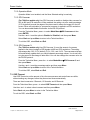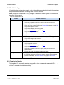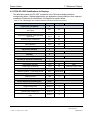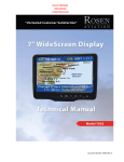
1
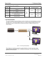
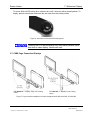
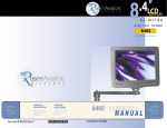
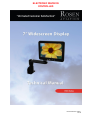
ELECTRONIC REVISION CONTROLLED Document Number 106211 Rev B Rosen Aviation 7” Widescreen Display Technical Manual, 7” Widescreen Display © 2013, 2014 by Rosen Aviation, LLC All Rights Reserved The information contained herein is proprietary to Rosen Aviation, LLC. No part of this publication may be reproduced, transmitted, transcribed, stored in a retrieval system, or translated into any language in any form by any means without the written authorization from Rosen Aviation, LLC, except as allowed under copyright laws. Disclaimer of Liability The information contained in this document is subject to change without notice. Because we are continuously improving and adding features to our products, Rosen Aviation, LLC reserves the right to change specifications without prior notice. Rosen Aviation, LLC shall not be liable for technical or editorial errors or omissions contained herein. Rosen Aviation, LLC 1020 Owen Loop South Eugene, OR 97402 541.342.3802 888.668.4955 Fax: 541.342.4912 www.rosenaviation.com Document Number: 106211 Template: 4.4.1.6FM2; Revision A; 12/06/12 Revision: Date: 04/17/14 B Page 2 of 31 Rosen Aviation 7” Widescreen Display Contents 1. INTRODUCTION .................................................................................................................5 1.1. Base Compatibility ........................................................................................................5 2. SYSTEM OVERVIEW .........................................................................................................6 2.1. High-definition Systems ................................................................................................7 3. INSTALLATION GUIDELINES ...........................................................................................7 3.1. Installing/Removing SlimLine Arm Assemblies .............................................................8 3.2. Stowing a Locking Arm Display ....................................................................................8 3.3. CVBS Pogo Connection Displays .................................................................................9 3.4. CVBS Micro-D Connection Displays ...........................................................................10 3.5. SDI Pogo Connection Displays ...................................................................................11 3.6. Base Installations ........................................................................................................12 3.6.1. CVBS Pogo Base Receptacles ....................................................................................... 12 3.6.2. SDI Pogo Base Receptacles........................................................................................... 12 3.6.3. CVBS Micro-D Base Receptacles ................................................................................... 13 3.7. Electrical Requirements ..............................................................................................13 3.8. Pinout Connections .....................................................................................................13 3.8.1. RS-232 Control ............................................................................................................... 13 4. INITIAL POWER UP .........................................................................................................14 5. DISPLAY TOUCH CONTROLS ........................................................................................14 5.1. Source Select .............................................................................................................14 6. OSD MENU OPTIONS ......................................................................................................15 6.1. Exit ..............................................................................................................................15 6.2. User Menu ..................................................................................................................16 6.2.1. Backlight ......................................................................................................................... 16 6.2.2. Aspect Ratio ................................................................................................................... 16 6.2.3. Scheme .......................................................................................................................... 17 6.3. Image Adjust Menu .....................................................................................................17 6.3.1. Scheme .......................................................................................................................... 17 6.3.2. Picture-quality Controls ................................................................................................... 18 6.3.3. Reset Scheme ................................................................................................................ 18 6.3.4. Image Adjust Advanced (Submenu) ............................................................................... 18 6.4. Info ..............................................................................................................................20 7. TECHNICIAN MENU .........................................................................................................21 7.1. Technician Advanced Submenu .................................................................................22 7.1.1. Factory Reset ................................................................................................................. 22 7.1.2. 3D Comb Filter ............................................................................................................... 22 7.1.3. Composite Sig (Signal) ................................................................................................... 22 7.1.4. AGC (Automatic Gain Control) ........................................................................................ 23 Document Number: 106211 Template: 4.4.1.6FM2; Revision A; 12/06/12 Revision: Date: 04/17/14 B Page 3 of 31 Rosen Aviation 7” Widescreen Display 7.2. Technician Mode Menu...............................................................................................23 7.2.1. Power Mode ................................................................................................................... 23 7.2.2. Operation Mode .............................................................................................................. 24 7.2.3. SDI Overscan ................................................................................................................. 24 7.2.4. SDI Overscan % ............................................................................................................. 24 7.3. OSD Timeout ..............................................................................................................24 7.4. Front Panel LED .........................................................................................................25 7.5. Source Select Menu ...................................................................................................25 8. MAINTENANCE: TENSION ADJUSTMENTS ..................................................................26 9. TECHNICAL REFERENCES AND SUPPORT .................................................................26 9.1. Troubleshooting ..........................................................................................................27 9.2. Cleaning the Display ...................................................................................................27 9.3. RTCA DO-160F Qualifications for Displays ................................................................28 9.4. Supported Video Resolutions .....................................................................................30 9.4.1. CVBS/Composite Resolutions ........................................................................................ 30 9.4.2. SDI Resolutions .............................................................................................................. 30 10. DEFINITIONS..................................................................................................................30 11. REVISION HISTORY ......................................................................................................31 Document Number: 106211 Template: 4.4.1.6FM2; Revision A; 12/06/12 Revision: Date: 04/17/14 B Page 4 of 31 7” Widescreen Display Rosen Aviation 1. INTRODUCTION Rosen’s new 7004 series of personal displays allow for direct upgrades for high-definition and Composite units with a variety of existing bases on your aircraft. In addition to the sleek, tabletstyle display, the touch-sense front panel enables source select capability directly from the front panel on select models depending on the base. The 7004 models differ depending on the plug-in arm configuration and input signal. All SDI models (7004-3xx) support 3G HD-SDI up to 1080p, and are compatible with the Rockwell Collins Venue™ system using RS-232. This manual describes the compatibility of bases and display models, and it provides general instructions about how to install the new arm-mounted displays onto your aircraft and confirm that they are functioning correctly. Note: Only trained and qualified personnel should perform installation and service. Technical drawings and the Technical Manual are available on the Rosen Aviation website at www.rosenaviation.com. From the home page, select the Products tab and browse by product category. Please contact Technical Support at 541.342.3802 if you need assistance locating product information. 1.1. Base Compatibility The tables below show which bases are compatible with the new 7004 displays. For a comparison of base-mounting diagrams, see Base Installations, beginning on page 12, to compare. Bases are sold separately. Table 1 Composite (CVBS) display and base compatibility Display Model Description 7004-013 7" Center mount, Non-locking arm 7004-060 7" Left mount, Non-locking arm Base Type Base Model & Aircraft Connections 0100-002 0100-004 DB9 with source select Molex/BNC without source select Micro-D 7004-061 7" Right mount, Non-locking arm 0100-005 7004-015 7" Center mount, Non-locking arm 0100-041 0100-042 DB9 with source select 7004-037 7" Center mount, Locking arm 0100-040 Molex/BNC without source select Document Number: 106211 Template: 4.4.1.6FM2; Revision A; 12/06/12 CVBS Pogo Revision: Date: 04/17/14 B Page 5 of 31 7” Widescreen Display Rosen Aviation Table 2 SDI display and base compatibility Display Model Description 7004-362 7”, SDI, Left mount, Non-locking SlimLine SDI arm 7004-363 7004-315 7004-337 7”, SDI, Right mount, Non-locking SlimLine SDI arm 7”, SDI, Center mount, Non-locking SlimLine SDI arm Base Type Base Model & Aircraft Connections 0100-344 RS-232 with source select 0100-342 RS-232 without source select SDI Pogo 7”, SDI, Center mount, Locking SlimLine SDI arm 2. SYSTEM OVERVIEW The typical installation of personal displays consists of multiple arm-mounted displays connected to a video source. The following figures show how to configure analog (standard definition) and HD displays to create a complete cabin entertainment system or integrate a display into an existing system. Composite DVD Player Personal Displays Composite Figure 1 Connecting analog displays These displays are typically connected to a video distribution unit, which provides a single Composite video signal (NTSC, PAL, or SECAM) to each display. The video distribution box performs the source selection. Document Number: 106211 Template: 4.4.1.6FM2; Revision A; 12/06/12 Revision: Date: 04/17/14 B Page 6 of 31 7” Widescreen Display Rosen Aviation 2.1. High-definition Systems SDI units display either standard definition (SD) or high-definition (HD) video using serial digital video input. In this configuration, the video is sourced by a digital video distribution switch or source and de-serialized into an SDI format. High-definition displays are typically installed in a system where the SDI video is distributed from a cabin management system and/or HD video distribution to each display. Blu-ray Player Blu-ray Player DVI/HDMI DVI/HDMI HD Distribution SDI Cabin Management System Personal Display SDI Personal Display Figure 2 Connecting HD displays 3. INSTALLATION GUIDELINES The 7” arm-mount displays plug in to round bases depending on the connector type and input signal. Ensure the correct orientation when plugging the arm into the base receptacle, as shown below, so that the alignment pin in the base follows the arm’s keyed slot connection and is not forced. Slot Alignment pin Figure 3 Arm and base interface Document Number: 106211 Template: 4.4.1.6FM2; Revision A; 12/06/12 Revision: Date: 04/17/14 B Page 7 of 31 7” Widescreen Display Rosen Aviation 3.1. Installing/Removing SlimLine Arm Assemblies To install a SlimLine arm assembly, press the arm button all the way in and push straight down on the arm into the plug body until it is secure in the base. Composite arm Arm button Arm button Plug body Plug body SDI arm Figure 4 SlimLine locking arm features To remove a SlimLine arm assembly, press the arm button in all the way and lift up on the display/arm assembly. 3.2. Stowing a Locking Arm Display SlimLine locking arm displays have two locking points at 0º and 180º to secure displays in a stowed position, without disconnecting power, during taxiing, takeoff, and landing (TTL). To stow a SlimLine locking arm display, rotate the arm to either 0º or 180 º until it locks. To deploy a SlimLine locking arm display, press the arm button halfway and rotate the arm away from the locked position. Arm rotation locks at 0º and 180º Figure 5 Stowing positions for SlimLine locking arm displays Document Number: 106211 Template: 4.4.1.6FM2; Revision A; 12/06/12 Revision: Date: 04/17/14 B Page 8 of 31 7” Widescreen Display Rosen Aviation To stow a SlimLine SDI locking arm, rotate the arm until it locks into either stowed position. To deploy, press the arm button and rotate the arm away from the locked position. Figure 6 Arm button on SlimLine SDI locking arms Touching the LCD with excessive force may leave pressure spots that show in video display. Handle with care. 3.3. CVBS Pogo Connection Displays P/N 7004-015, 7" Display: Pogo, non-locking, center P/N 7004-037, 7" Display: Pogo, locking, center Figure 7 Pogo connection displays use base receptacles 0100-040, 0100-041, & 0100-042 Document Number: 106211 Template: 4.4.1.6FM2; Revision A; 12/06/12 Revision: Date: 04/17/14 B Page 9 of 31 7” Widescreen Display Rosen Aviation 3.4. CVBS Micro-D Connection Displays P/N 7004-013, 7" Display: Micro-D, non-locking, center P/N 7004-060, 7" Display: Micro-D, non-locking, left P/N 7004-061, 7" Display: Micro-D, non-locking, right Figure 8 Micro-D connection displays use base receptacles 0100-002, 0100-004, & 0100-005 Document Number: 106211 Template: 4.4.1.6FM2; Revision A; 12/06/12 Revision: Date: 04/17/14 B Page 10 of 31 Rosen Aviation 7” Widescreen Display 3.5. SDI Pogo Connection Displays P/N 7004-315, 7" Display: non-locking, center P/N 7004-362, 7" Display: non-locking, left P/N 7004-337, 7" Display: locking, center P/N 7004-363, 7" Display: non-locking, right Figure 9 SDI Pogo-style connection displays use base receptacles 0100-344 & 0100-342 Document Number: 106211 Template: 4.4.1.6FM2; Revision A; 12/06/12 Revision: Date: 04/17/14 B Page 11 of 31 7” Widescreen Display Rosen Aviation 3.6. Base Installations Consult the Outline and Installation drawing to assist with the installation process. Pay close attention to the dimensions and fastener depths required when considering installation requirements. The 7004 displays are compatible with the base designs, as shown below. Bases mount on either a vertical or a horizontal surface, typically with a minimum of four screws (two per flange). For base pinout information, refer to the display drawings on the Rosen Aviation website. 3.6.1. CVBS Pogo Base Receptacles P/N 0100-041 Base Receptacle: Pogo, DB9 harness, universal mount P/N 0100-042 Base Receptacle: Pogo, DB9 harness, horizontal mount CVBS Pogo-style connection P/N 0100-040 Base Receptacle: Pogo BNC/Molex harness, universal mount Figure 10 CVBS Pogo-style base receptacles 3.6.2. SDI Pogo Base Receptacles P/N 0100-344 Base Receptacle: BNC/DB9 Harness, SDI, RS-232, with source select SDI Pogo-style connection Note: Base Receptacle P/N 0100-342 is also compatible with the 7004 series, but it does not have source select. Figure 11 SDI Pogo-style base receptacle Document Number: 106211 Template: 4.4.1.6FM2; Revision A; 12/06/12 Revision: Date: 04/17/14 B Page 12 of 31 7” Widescreen Display Rosen Aviation 3.6.3. CVBS Micro-D Base Receptacles P/N 0100-002 Base Receptacle: Micro-D, DB9 harness, universal mount P/N 0100-004 Base Receptacle: Micro-D, DB9 harness, horizontal mount Micro-D-style connection P/N 0100-005 Base Receptacle: Micro-D BNC/Molex harness, universal mount Figure 12 CVBS Micro-D-style base receptacle 3.7. Electrical Requirements Nominal voltage 28VDC / 0.30A Inrush Current 20A for 250 microseconds Op Voltage/Current Range 18VDC/0.45A – 32VDC/0.27A Max Power Consumption: 8.6 W 3.8. Pinout Connections There are several ways to connect a personal display to an aircraft’s entertainment system. Use the pinout descriptions on the monitor’s Outline and Installation drawing to assist in completing the wiring connections. Note: This display is for entertainment purposes only; connect to a non-critical power bus. 3.8.1. RS-232 Control The SDI displays can be controlled via a cabin management system using RS-232, if an RS-232 connection is present on the configuration. The display connects to 28VDC aircraft power and receives video through a video distribution amplifier or directly from video sources. For a copy of the RS-232 External Controller Message Formats (P/N 9002934), please contact Rosen Aviation Technical Support at 541.342.3802. Document Number: 106211 Template: 4.4.1.6FM2; Revision A; 12/06/12 Revision: Date: 04/17/14 B Page 13 of 31 7” Widescreen Display Rosen Aviation 4. INITIAL POWER UP Make sure to turn off the power before connecting the harnesses. 1. 2. 3. 4. 5. Ensure low impedance ground connections on the base. Ensure that 28VDC power supply is OFF. Connect the power supply and video source to the appropriate harnesses. Plug in the display/arm assembly. Supply power and wait for a video signal on the screen. The default power setting is Auto On. When cycling power, leave unit off for 20 seconds before restoring power. 5. DISPLAY TOUCH CONTROLS The 7004 displays have touch-sense buttons on the front panel to control all operating functions; however, the 7004-3xx models can be controlled from the Rockwell Collins Venue system. Use the plus (+) and minus (–) buttons to navigate through the options. Menu opens the OSD and accepts option values Forward right/up Source Select switches input sources Power Backward left/down Power LED Figure 13 Touch controls and functions 5.1. Source Select Source Select is available depending on the base and video distribution installations on the aircraft. To change between video sources, press Source Select, either on the front panel or the remote control. Document Number: 106211 Template: 4.4.1.6FM2; Revision A; 12/06/12 Revision: Date: 04/17/14 B Page 14 of 31 7” Widescreen Display Rosen Aviation 6. OSD MENU OPTIONS The OSD contains screen settings and options in menus and informational readouts that display over the image, as shown below. Press Menu on the front panel to open the Main Menu, as shown in Figure 15 on page 15. Press + and – to navigate within the menu pages, options, and values columns. Select the Back option to switch menu pages. The yellow highlighted area shows the currently selected option. Press Menu and + to move right across the menu page options and values. Press Menu and – to move left across the menu page options and values. Press + to access the menu page options Press – to access menu pages. The selected menu page is highlighted. Press + to access the menu option values Figure 14 OSD menu pages The available menu options will vary depending on which source signal is active. Press Menu to choose a setting or an option. Select the Back option to switch menu pages. Select Exit and then press Menu to close the OSD and save the settings. Note: The on-screen display will timeout and automatically close after no screen activity for a preset amount of time, which is adjustable on the Technician Menu OSD Timeout option. See Section 7.3, OSD Timeout, on page 24. 6.1. Exit Use Exit to close the OSD. When you press Menu, the OSD opens to this screen, as shown below. Press Menu again to close the OSD from this screen. Press + and – to access the other menu pages in the OSD. From other settings within the OSD, select Back and Exit to close the OSD. Figure 15 Opening screen for the Main Menu Document Number: 106211 Template: 4.4.1.6FM2; Revision A; 12/06/12 Revision: Date: 04/17/14 B Page 15 of 31 7” Widescreen Display Rosen Aviation 6.2. User Menu The User Menu contains frequently used control settings. Press Menu to open the Main Menu, and press – and Menu to access the User Page options. Press + or – to select a User option, and then press Menu to change its value. Select Back to return to the menu pages Figure 16 User menu options 6.2.1. Backlight Use this setting to adjust the intensity of the LCD backlight. From the User page, press + and – to select Backlight, and then press Menu to open the control bar shown below. Press + and – to change the value on the control bar accordingly. Press Menu to set the backlight brightness and close the control bar. Figure 17 Backlight option 6.2.2. Aspect Ratio Use Aspect Ratio to adjust the picture expansion to match the encoding of the source image most closely. Select UserAspect Ratio and then press Menu. To switch the display between aspect ratio modes (described below), press the + and – buttons. Watch for proportional changes in the background picture and choose the optimal mode for the source. Press Menu to set the mode and select BackExit to close the OSD. Full Screen: (Default) Displays standard 4:3 source video in 16:9 aspect ratio by expanding the image horizontally. Circles will appear as ovals in the central and outer portions of the screen. If the source image is letterboxed, there will be black bars at the top and bottom of the image. A 16:9 widescreen source will fill the screen with minimal distortion. Document Number: 106211 Template: 4.4.1.6FM2; Revision A; 12/06/12 Revision: Date: 04/17/14 B Page 16 of 31 7” Widescreen Display Rosen Aviation Pillar Box: A standard 4:3 source image will appear with vertical black bars on the left and right side of the image. If the image source is letterboxed, then there will also be horizontal bars at the top and bottom of the image as well. Letter Box Expanded: Expands the source video in the vertical and horizontal dimensions to fill the display screen. Letterbox-format DVDs will have small or no bars showing in this mode, while 4:3 aspect video sources will expand beyond the screen boundaries and appear cropped. 6.2.3. Scheme There are two default color settings or schemes: Natural and Vivid. If the screen colors are not what you expect, select Scheme and press + and – to toggle between the settings. The background picture’s colors change as you toggle between the settings. Vivid uses a higher color saturation level above the Natural level. Try both schemes to determine which one you like best before adjusting the other picture quality settings. Select UserScheme and then press Menu to access the settings. Select the setting and press Menu to accept the changes, and then select BackExit to close the OSD. 6.3. Image Adjust Menu Use the Image Adjust menu options, as shown below, to control the color and picture quality. Highlight Image Adjust and press Menu to access the Image Adjust menu options. Press + or – to select an Image Adjust option, and then press Menu to change its value. Picturequality controls Figure 18 Image Adjust menu options 6.3.1. Scheme Scheme is also available from the Main MenuUser page. For information about how this option works, see Section 6.2.3, Scheme, on page 17. Changing the Scheme also affects changes that you make to the User menu settings and is source specific. Document Number: 106211 Template: 4.4.1.6FM2; Revision A; 12/06/12 Revision: Date: 04/17/14 B Page 17 of 31 7” Widescreen Display Rosen Aviation 6.3.2. Picture-quality Controls The Brightness, Contrast, Saturation, Hue, and Sharpness menu options use control bars to fine-tune different aspects of the picture quality. To adjust these options, press Menu and – to select Image Adjust. Choose a menu option, and then press Menu to open a control bar and adjust the value, similar to Figure 19, shown below. Press + or – to increase or decrease the control’s value. Press Menu to set the menu option and close the control bar. Select BackExit to close the OSD. Figure 19 Sample picture-quality control bar 6.3.3. Reset Scheme Restores the values of the current scheme to their default settings, and it affects only the current source. Use Reset Scheme to revert to the default screen colors if the other Image Adjust options did not correct the screen quality. Select Image AdjustReset Scheme and then press Menu. Select BackExit to close the OSD. For information about the different Scheme modes, see Section 6.2.3 on page 17. 6.3.4. Image Adjust Advanced (Submenu) Use the Image Adjust Advanced submenu options, as shown below, to fine-tune the primary screen colors and to restore the monitor’s factory screen settings. Press Menu and + or – to select Image AdjustAdvanced, and then press Menu. To close the menu, select the Back option, or select BackExit to close the OSD. Figure 20 Advanced submenu options Document Number: 106211 Template: 4.4.1.6FM2; Revision A; 12/06/12 Revision: Date: 04/17/14 B Page 18 of 31 7” Widescreen Display Rosen Aviation 6.3.4.1. Color Temperature Use the Color Temperature options to change the warmth of the picture in all sources. When you select Color Temperature, the screen changes, and a toggle appears to switch between User and 6500K, as shown below. Figure 21 Color Temperature options Press – and Menu to open the Color Temperature Page. Press – to access the User setting and then press Menu and – to access the individual colors. 6.3.4.1.1. Color Levels: Red, Green, Blue Setting the Color Temperature to User will make the Red, Blue, and Green options active. Each color adjusts the low-level registers of its respective color value in the picture. Select the Image AdjustAdvancedColor Temperature and press Menu. Set Color Temperature to User, and then press Menu. Press – to choose a color level, and then press Menu to open a control bar to adjust the value, similar to Figure 22 shown below. Red: Press – to show more cyan-colored tones, and press + to intensify the red tones. Green: Press – to show more magenta tones, and press + to intensify the green tones. Blue: Press – to show more yellow tones, and press + to intensify the blue tones. Press Menu to set the color and close the control bar. Select BackExit to close the OSD. Figure 22 Sample color-level control bar Document Number: 106211 Template: 4.4.1.6FM2; Revision A; 12/06/12 Revision: Date: 04/17/14 B Page 19 of 31 7” Widescreen Display Rosen Aviation 6.3.4.2. Restore Defaults This option restores the default screen settings from the user menus for all video sources. It does not erase Technician Menu settings or change the internal time and date. A Defaults Restored message appears in the lower corner of the menu after the restore is complete. Status message Figure 23 Restore Defaults option 6.4. Info Use the Information page to review operating status, view details about the display, and access the Technician Menu. To open the Info page, press Menu and then – to navigate to Info. Notes: Press Menu and + to highlight the Back option—required to access the Technician Menu. The firmware (FW) fields vary by model and are subject to change. Back option active Use Info to verify video source and resolution settings. Figure 24 Info page Document Number: 106211 Template: 4.4.1.6FM2; Revision A; 12/06/12 Revision: Date: 04/17/14 B Page 20 of 31 7” Widescreen Display Rosen Aviation 7. TECHNICIAN MENU To protect the display from accidental or unintentional adjustments, the Technician Menu is accessible only with a special button combination. To avoid repeating this button sequence after each change, the menu remains active until you manually close it. Whenever there is a change to the OSD settings, exit the menu, and cycle power for the changes to be saved. To open the Technician Menu, start with the display on, and press the following buttons in this order: 1. Press Menu and – to select the Info page. 2. With the Back option highlighted on the Info page, press + – + – + + +, and then press Menu. 3. The Technician Menu opens. Figure 25 Technician Main Menu To navigate the menu options, press + or – on the front panel. To close the Technician Menu and return to the Main Menu, select the Back option and press Menu. To close the OSD, select Exit and then press Menu. Note: The Main Menu options are not selectable while the Technician Menu is open. Document Number: 106211 Template: 4.4.1.6FM2; Revision A; 12/06/12 Revision: Date: 04/17/14 B Page 21 of 31 7” Widescreen Display Rosen Aviation 7.1. Technician Advanced Submenu This submenu provides installers and technicians more advanced controls of the image. The input signal determines which options will appear in the Technician Advanced submenu. The only options available on SDI models Additional options available on Composite models Figure 26 Technician Advanced submenu 7.1.1. Factory Reset Choose this option to perform a complete factory restore. Factory Reset returns all options with pre-determined defaults in both the User and Technician menus to their factory default settings. Highlight AdvancedFactory Reset and press Menu. A Reset Complete message appears after the display restores the default settings. Remember to power cycle after performing a Factory Reset. 7.1.2. 3D Comb Filter (Composite only) When set to Enabled (default), the display will eliminate dot crawl and some noise on stationary portions of the picture. Highlight Advanced3D Comb Filter and press Menu. Use + and – to set the option Enabled or Disabled, and then press Menu. Select Back and press Menu to return to the Technician Menu. To exit the OSD, select Back and Exit. 7.1.3. Composite Sig (Signal) (Composite only) This is a read-only screen that shows the signal strength of the currently viewed Composite source. Composite Signal strength ranges from 0 to 1.25 Vpp in 0.25V increments. It will read NA (not available) if a Composite source is not active or the AGC (Automatic Gain Control) (below) is set to Off. Document Number: 106211 Template: 4.4.1.6FM2; Revision A; 12/06/12 Revision: Date: 04/17/14 B Page 22 of 31 7” Widescreen Display Rosen Aviation 7.1.4. AGC (Automatic Gain Control) (Composite only) This option is a signal compensation tool that will accommodate for strong and weak Composite signals. Highlight AdvancedAGC and press Menu. Use + and – to set the option On (default) or Off, and then press Menu. Select Back and press Menu to return to the Technician Menu. To exit the OSD, select Back and Exit. 7.2. Technician Mode Menu Use the Technician Mode Menu options to specify the Power Mode and to access the SDI Overscan settings (SDI models only). From the Technician Main Menu, select Mode Menu and then press Menu to open the submenu, as shown below. Figure 27 Technician Mode Menu 7.2.1. Power Mode Use Power Mode to set the display’s initial power state. From the Technician Menu, press – to select Mode MenuPower Mode and then press Menu. Use the + and – to set the option and then press Menu. Options include the following: Auto On: The display always starts up in the ON state when 28V is applied (default). Auto Off: The display always starts up in the standby state when 28V is applied. Restore Previous: The display returns to the previous power settings after any power interruption. Select Back and press Menu to return to the Technician Menu. To exit the OSD, select Back and Exit. Document Number: 106211 Template: 4.4.1.6FM2; Revision A; 12/06/12 Revision: Date: 04/17/14 B Page 23 of 31 Rosen Aviation 7” Widescreen Display 7.2.2. Operation Mode Operation Mode is not enabled, and the None Selected setting is read-only. 7.2.3. SDI Overscan (For 7004-3xx models only) Use SDI Overscan to enable or disable video overscan for SDI at 480i and 576i resolutions. When enabled, the setting cuts off a small percentage (2.5% by default) around the edges of the picture and it resizes the image to fit the full screen. When set to disabled, a zero percent overscan is applied to all SDI resolutions. You can also enable/disable this feature via the RS-232 protocol. From the Technician Menu, press – to select Mode MenuSDI Overscan and then press ENTER. Use the + and – to set the option to Enabled or Disabled, and then press Menu. Select Back and press Menu to return to the Technician Menu. To exit the OSD, select Back and Exit. 7.2.4. SDI Overscan % (For 7004-3xx models only) Use SDI Overscan % to set the amount of overscan applied to the picture’s edges of SDI signals at 480i and 576i resolutions. The setting percentages are 0.0%, 2.5% (default), 3.0%, 5.0%, and 10.0%. The overscanned image will automatically update when you switch between percentage values. You do not have to cycle power for the change to take effect. You can also change the overscan value via the RS-232 protocol. From the Technician Menu, press the – to select Mode MenuSDI Overscan % and then press Menu. Use the + and – to set the percentage option and then press Menu. Select Back and press Menu to return to the Technician Menu. To exit the OSD, select Back and Exit. 7.3. OSD Timeout Use OSD Timeout to set the amount of time the menu screens and control bars are visible, without making any changes, before they timeout and close automatically. There are three increments: 6 Seconds, 15 Seconds, and 30 Seconds. From the Technician Menu, press – to select OSD Timeout and then press Menu. Use the + and – to select a time increment and then press Menu. Select Back and press Menu to return to the Technician Menu. To exit the OSD, select Back and Exit. Document Number: 106211 Template: 4.4.1.6FM2; Revision A; 12/06/12 Revision: Date: 04/17/14 B Page 24 of 31 7” Widescreen Display Rosen Aviation 7.4. Front Panel LED The Front Panel LED option turns the power LED on or off. When the option is Disabled, the power LED will be black. Power LED Figure 28 Front panel touchpad When it is On, the power LED will have the following states: Green indicates the display is receiving power. Amber indicates the display is in standby mode. Red indicates the display is registering an error. Black indicates the display is receiving no power. Highlight TechnicianFront Panel LED and press Menu. Use the + and – to set the option Enabled or Disabled, and then press Menu. Select Back and press Menu to return to the Technician Menu. To exit the OSD, select Back and Exit. 7.5. Source Select Menu Use this submenu to adjust the Pulse Width and Repeat Delay of the source select signal. Pulse Width specifies the amount of time the pulse is active (when switching sources), and Repeat Delay specifies the amount of time between pulses being sent from the display. Highlight Technician MenuSource Select, press – to select a setting, and then press Menu to access the option. Use the + and – buttons to increase or decrease the length of time the pulse width and repeat delay are active (in milliseconds), and then press Menu. The Pulse Width is always less than the Repeat Delay. Figure 29 Source Select menu options and their default values Select Back and press Menu to return to the Technician Menu. To exit the OSD, select Back and Exit. Document Number: 106211 Template: 4.4.1.6FM2; Revision A; 12/06/12 Revision: Date: 04/17/14 B Page 25 of 31 7” Widescreen Display Rosen Aviation 8. MAINTENANCE: TENSION ADJUSTMENTS The 7004 series displays require fewer tension adjustments than the older 7002 models. The new monitor design features a lifetime friction hinge, so no tilt adjustment is ever required. There are no adjustment points on the SlimLine SDI arms; however, the Composite arm mounts have two adjustment points. Adjust the screen pivot and arm rotation, if necessary, by torquing the socket head cap screws (SHCS), as shown below. Tighten both screws just until the screen pivots and the arm rotates with only minor resistance. Rotation adjust: 8-32 SHCS Pivot adjust: 4-40 SHCS Figure 30 Tension adjustment points for Composite arm mount displays 9. TECHNICAL REFERENCES AND SUPPORT Check the Rosen Aviation website to ensure that you are working with the most current revision of technical documentation. If you need assistance in configuring a personal display to work with an HD system, please contact Rosen Aviation Technical Support at 541.342.3802. Table 3 Technical references Product Part Number Location 9002934 Contact Rosen Technical Support Displays’ Outline & Installation Drawings 7004-xxx-CD www.rosenaviation.com Base Outline & Installation Drawings 0100-xxx-CD www.rosenaviation.com RS-232 External Controller Message Formats Document Number: 106211 Template: 4.4.1.6FM2; Revision A; 12/06/12 Revision: Date: 04/17/14 B Page 26 of 31 7” Widescreen Display Rosen Aviation 9.1. Troubleshooting If the display does not function properly, refer to the following troubleshooting table for symptoms and possible solutions before contacting Rosen Technical Support. Note: Always use a multimeter to verify voltages. Check actual results against the requirements described in this manual. Table 4 Troubleshooting tips Problem No video (signal) Screen is black Image flickers Distorted Image Wrong Colors Possible Solutions Verify that the display is turned on and the video is on. Verify that a signal is reaching the display using an oscilloscope or another display. Check the Power Control Pin. See the Power Mode settings on page 23. Verify that the pinout is correct. Verify that the display is receiving power. Check the Power Mode settings on page 23. Verify that the pinout is correct. Verify that the video source is on and playing. Verify all connections between the source and the display. Try turning on the AGC (Automatic Gain Control) setting on page 23. Verify that the signal cable is secure. Verify that the vertical frame frequency is 60 Hz or less. Verify proper connections, per the latest O&I drawings. Verify supported resolution. Check the Power Mode settings on page 23. Verify that the pinout is correct. Verify that a signal is reaching the display using an oscilloscope or another display. Examine the display for pinched or damaged cables. Verify proper connections, per the latest technical drawings. If the screen colors are not what you expect, reset the current scheme. For more information, see Reset Scheme on page 18 and Restore Defaults on page 20. 9.2. Cleaning the Display To clean the LCD, very gently wipe the screen with a clean, commercially approved LCD cleaning cloth and alcohol-free LCD cleaning solution. Use one firm cleaning motion instead of circular or repeated side-to-side scrubbing. Document Number: 106211 Template: 4.4.1.6FM2; Revision A; 12/06/12 Revision: Date: 04/17/14 B Page 27 of 31 7” Widescreen Display Rosen Aviation 9.3. RTCA DO-160F Qualifications for Displays The table below shows the DO-160F compliance of the 7004 series displays and their corresponding bases. Omitted categories are not applicable to these products or their expected installations. Reference the Qualification Test Reports for specific details. Table 5 The 7004 displays are compliant with the following DO-160F test criteria Description Section Temperature and Altitude 4 Category Ground Survival/Short-Time Operating Low Temp 4.5.1 A1 Operating Low Temperature 4.5.2 A1 Ground Survival/Short-Time Operating High Temp 4.5.3 A1 Operating High Temperature 4.5.4 A1 Altitude 4.6.1 A1 Decompression 4.6.2 A1 Overpressure 4.6.3 A1 Temperature Variation Temperature Variation Humidity Humidity Operational Shocks & Crash Safety Comments 5 5.3.1 C 6 6.3.1 A 7 Operational Shocks 7.2.1 B (6G) Crash Safety (Impulse) 7.3.2 B (20G) Crash Safety (Sustained) 7.3.3 B (20G) SDI / (9G) CVBS Vibration Random Vibration – Fixed Wing Aircraft Magnetic Effect Magnetic Effect 8 8.5.2 S (Curve B) 15 15.3 Power Input 16 Normal Operating Conditions (DC) 16.6.1 Z Average Value Voltage (DC) 16.6.1.1 Z Ripple Voltage (DC) 16.6.1.2 Z Momentary Power Interruptions (DC) 16.6.1.3 Z Normal Surge Voltage (DC) 16.6.1.4 Z Engine Starting Under Voltage Operation (DC) 16.6.1.5 Z Document Number: 106211 Template: 4.4.1.6FM2; Revision A; 12/06/12 Revision: Date: 04/17/14 B Page 28 of 31 7” Widescreen Display Rosen Aviation Description Section Abnormal Operating Conditions 16.6.2 Category Voltage Steady State (DC) 16.6.2.1 Z Momentary Under Voltage (DC) 16.6.2.3 Z Abnormal Surge Voltage (DC) 16.6.2.4 Z Voltage Spike Voltage Spike Audio Frequency Conducted Susceptibility AF Conducted Susceptibility - Power Inputs Induced Signal Susceptibility 17 17.4 A 18 18.3.1 Z 19 Magnetic Fields Induced Into Equipment 19.3.1 AC Magnetic Fields Induced Into Interconnecting Cables 19.3.2 AC Electric Fields Induced Into Interconnecting Cables 19.3.3 AC Spikes Induced Into Interconnecting Cables 19.3.4 AC Radio Frequency Susceptibility 20 Conducted Susceptibility (CS) – 10kHz to 400MHz 20.4 T Radiated Susceptibility (RS) – 100MHz to 18GHz 20.5 T Emission of Radio Frequency Energy Comments 21 Conducted RF Emission 21.4 B/M See Cat. on O&I drawing Radiated RF Emission 21.5 B/M See Cat. on O&I drawing Electrostatic Discharge (ESD) Electrostatic Discharge (ESD) Flammability Document Number: 106211 Template: 4.4.1.6FM2; Revision A; 12/06/12 25 25.5 A 26 N/A Flammability testing in accordance with 14 CFR 25.853 Appendix F Revision: Date: 04/17/14 B Page 29 of 31 7” Widescreen Display Rosen Aviation 9.4. Supported Video Resolutions 9.4.1. CVBS/Composite Resolutions NTSC (480i/29) PAL (576i/25) SECAM (576i/25) RS-170 B&W (480i/29) The software continually checks and chooses the appropriate color decoder (NTSC, PAL, or SECAM) based on the analog input signal. 9.4.2. SDI Resolutions SMPTE 259M 480i/29 576i/25 SMPTE 292M 720p/50, 720p/59, 720p/60 1080i/25, 1080i/29, 1080i/30 1080p/23, 1080p/24, 1080p/25, 1080p/29, 1080p/30 SMPTE 424M 1080p/50, 1080p/59, 1080p/60 10. DEFINITIONS 3G HD-SDI Newer, high-definition serial digital interface with a single 2.970 G/bit/s serial link A Amps AF Audio frequency CFR Code of Federal Regulations CVBS Color Video Blanking and Sync (Composite video signal) DVI Digital Visual Interface EUT Equipment under test HD High Definition HDMI High Definition Multimedia Interface HD-SDI High Definition Serial Digital Interface LCD Liquid Crystal Display LED Light emitting diode Document Number: 106211 Template: 4.4.1.6FM2; Revision A; 12/06/12 Revision: Date: 04/17/14 B Page 30 of 31 7” Widescreen Display Rosen Aviation NTSC National Television Standards Committee; an analog video standard used in the United States, Canada, Japan, Mexico, the Philippines, South Korea, Taiwan, and some other countries O&I Outline and Installation (drawing) OSD On Screen Display – the actual user/technician menu, and any informational readouts displayed on the image. P/N Part Number PAL Phase alternate (by) line – the analog video specification used by most European countries and their former colonies worldwide PC Personal computer RF Radio frequency RS-232 Standard for serial binary data interchange RTCA Radio Technical Commission for Aeronautics SDI Serial Digital Interface SECAM (Séquentiel couleur à mémoire; French for "sequential color with memory"), an analog color video system first used in France SMPTE Society of Motion Picture and Television Engineers – timecode frame rates SHCS Socket head cap screw TTL Taxiing, takeoff, and landing V Volts VDC Volts direct current VGA Video Graphics Array Vpp Volts peak-to-peak W Watts 11. REVISION HISTORY Revision E is limited to draft or prototype documents. Revisions I, O, Q, S, X and Z are not to be used. Revision Date A 10/09/13 Initial release 13-0370 B 04/17/14 Corrected CVBS Micro-D Base part numbers 14-0143 Document Number: 106211 Template: 4.4.1.6FM2; Revision A; 12/06/12 Revision Description EC Revision: Date: 04/17/14 B Page 31 of 31