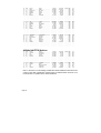
1
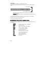
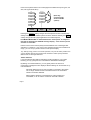
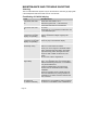
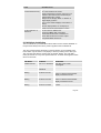
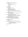
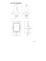
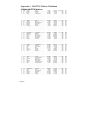
ICS NAV6 range User Guide Important Information This equipment is not approved for use by SOLAS convention vessels within the Global Maritime Distress and Safety System (GMDSS) It is intended for use by leisure craft and other non-SOLAS vessels wishing to participate within GMDSS Safety Warnings Do not use the sensor as a grab-handle This instrument is for use as an aid to sailors and should not lead to a reduction in the level of good seamanship required at all times Reception of messages cannot always be guaranteed as this depends on local radio propagation The correct magnetic variation must be input at the navigation instruments (e.g. GPS, electronic compass) for the accurate display of COG, set, waypoint bearing and heading. The technical data, information and illustrations contained in this publication were to the best of our knowledge correct at the time of going to print. We reserve the right to change specifications, equipment, installation and maintenance instructions without notice as part of our policy of continuous product development and improvement. No part of this publication may be reproduced, stored in a retrieval system or transmitted in any form, electronic or otherwise without permission in writing from McMurdo Limited. No liability can be accepted for any inaccuracies or omissions in the publication, although every care has been taken to make it as complete and accurate as possible. Copyright 2004, McMurdo Limited. All rights reserved. Contents User Guide .............................................................................................................2 Quick Start..............................................................................................................2 Introduction.............................................................................................................3 What Is NAVTEX? ..............................................................................................3 How Does NAVTEX Work? ................................................................................3 ICS NAV6 Features ................................................................................................3 The ICS NAV6 range..........................................................................................3 Display Unit ........................................................................................................4 NAVTEX Sensor.................................................................................................4 Advanced Operation.............................................................................................12 NAVTEX Mode .....................................................................................................12 NAVTEX Mode, Message View ........................................................................12 NAVTEX Mode, Print View§ .............................................................................13 NAVTEX Mode, Sort View................................................................................13 NAVTEX Mode, Filter View ..............................................................................14 Navigate Mode§ ...................................................................................................17 Setup Mode ..........................................................................................................21 Setup Mode, General View, LCD Page ............................................................21 Setup Mode, General View, Options Page .......................................................23 Setup Mode, NAVTEX View, Options Page .....................................................24 Setup Mode, NAVTEX View, Options Page, Print Setup§................................25 Setup Mode, NAVTEX View, 518 and 490 Names Pages................................26 Setup Mode, NAVTEX View, 518 and 490 Names, Station Database Setup ...26 Setup Mode, NAVTEX View, Monitor Page......................................................28 Setup Mode, Navigate View, Options Page§....................................................29 Setup Mode, Navigate View, User View Page§................................................29 Setup Mode, Navigate View, Monitor Page§ ....................................................30 Alarm Operation ...................................................................................................31 Output to a PC or Plotter§ ....................................................................................31 Maintenance and Trouble Shooting......................................................................32 Cleaning ...........................................................................................................32 Faultfinding ICS NAV6 display .........................................................................32 ICS NAV6hub faultfinding.................................................................................33 User Serviceable Parts.....................................................................................34 Software Upgrade.............................................................................................34 Fuses................................................................................................................34 Specification .........................................................................................................35 Outline Drawings ..................................................................................................39 Appendix I: NAVTEX Station Database................................................................39 Appendix I: NAVTEX Station Database................................................................40 Appendix II: Message Type Indicators .................................................................43 Appendix VII: ICS NAV6 Menu Navigation ...........................................................44 § See Page 2 for an explanation of this symbol Congratulations on purchasing this ICS NAV6 product. It is not only an excellent NAVTEX receiver, but a first class instrument repeater. It may be the only display you will ever need at your navigation position. We hope that it gives you many years of reliable service. Please take the time to read this manual carefully as it contains some essential information regarding the operation and maintenance of the product and a useful background to the NAVTEX system. We recommend that you regularly visit the McMurdo product website www.mcmurdo.co.uk for information on updates, the availability of software enhancements, further options and support. The support pages contain frequently asked questions about the ICS NAV6 that you may find useful. There is also a NAVTEX database providing a list of operational NAVTEX stations and their details. . Page 1 USER GUIDE This user guide describes the operation of the ICS NAV6plus, ICS NAV6Aplus, ICS NAV6dual and ICS NAV6repeater equipments. Not all the menu features described are provided by the ICS NAV6dual. Where this is the case, the symbol § is used to mark the feature. The ICS NAV6repeater will display NAVTEX menu pages only when incorporated with a ICS NAV6 system or ICS NAV6 sensor. Installation instructions are provided in the separate NAV6 range Installation Guide. Further installation information is furnished separately with each ICS NAV6 ancillary instrument. It is recommended that installation be carried out be a recognised marine installation engineer. QUICK START You will find the NAV6 extremely easy to operate. Please don't be intimidated by the comprehensive nature of this manual. In reality, receiving your first NAVTEX messages could not be simpler. • Follow the installation guidelines • Re-check the cable connection • The ICS NAV6 system has no ON/OFF switch, it will start up as soon as power is applied. • If you have not connected a GPS navigation receiver, make sure that you set the date and time on the screen which will appear at start up. • Wait for your first NAVTEX message. If you are within range of a NAVTEX transmitter, you should not need to wait for more than four hours. • Refer to “Appendix VII: ICS NAV6 Menu Navigation” for an overview of the available operating modes & how they relate to each other. • Read the “Basic Operation” section to find out how to use some of the commonly used features of this product • If you then want to get the best from the system, read the rest of the manual! Page 2 INTRODUCTION What Is NAVTEX? NAVTEX is a worldwide system for the broadcast and automatic reception of maritime safety information (MSI) in English by means of a narrow-band directprinting telegraphy. NAVTEX provides shipping with navigational and meteorological warnings and urgent information. NAVTEX is an element of the IMO/IHO worldwide Navigational Warning Service (WWNWS) as defined by IMO Assembly Resolution A.706(17). It is included within the Global Maritime Distress and Safety System (GMDSS). Since 1 August 1993, a NAVTEX receiving capability has become mandatory equipment for certain vessels under the provisions of the International Convention for the Safety of Life at Sea (SOLAS). NAVTEX broadcast information is available to all seafarers, free of charge. How Does NAVTEX Work? NAVTEX transmissions are sent from stations situated worldwide. The power of each transmission is regulated to avoid the possibility of interference between transmitters. Each station is allocated a 10-minute time slot every 4 hours so that many stations can share the same frequency. Stations typically have a transmission range of 250 – 300 Nm. ICS NAV6 FEATURES The ICS NAV6 range ICS NAV6plus full feature NAVTEX with NMEA repeater instrument displays, includes dual channel NAVTEX sensor with 10m sensor cable. ICS NAV6Aplus full feature dual channel NAVTEX with NMEA repeater instrument displays, supports a wide variety of antenna types such as an insulated backstay wire or active and passive whip antenna systems. ICS NAV6dual dual channel NAVTEX only, includes dual channel NAVTEX sensor with 10m sensor cable. ICS NAV6repeater stand alone NMEA repeater instrument display, can be connected to ICS NAV6plus/Aplus NAVTEX system using a ICS NAV6hub Page 3 Feature Dual receiver NMEA Auto station NMEA GPS Display NMEA instrument display NMEA Logging Display backlight Printer / data output Antenna options ICS ICS ICS ICS NAV6dual NAV6plus NAV6Aplus NAV6repeater x x x x x x x x x x x x x x x x x x x x x x Note: ICS NAV6dual has no PC or printer interface connection. Display Unit • • • • • • • The Display Unit has a high resolution backlit LCD. The display unit contains a large non-volatile memory to store NAVTEX messages. Messages can be filtered and sorted. The ICS NAV6plus and ICS NAV6Aplus can act as an NMEA instrument repeater and are capable of displaying data in a choice of formats. The ICS NAV6plus and ICS NAV6Aplus can be connected to a printer or computer to print NAVTEX messages and Navigation logs. Audible and visible alarms can be set up to indicate reception of SAR and/or New Messages. A sleep mode allows long standby periods with minimum power consumption, such as when the vessel is left in a marina with main batteries being trickle charged from the shore. NAVTEX Sensor • • • The Sensor Unit contains dual receivers that can receive on both 490kHz and 518kHz simultaneously. The ICS NAV6plus and ICS NAV6dual have a dual channel NAVTEX sensor unit. ICS NAV6Aplus has the ability to connect to a wide range of remote antenna types by using the NAVTEX Receiver Unit Page 4 BASIC OPERATION The ICS NAV6 is a flexible & powerful tool for receiving, storing & viewing NAVTEX messages. To assist you in getting the best from your ICS NAV6 equipment, read this section which contains short cuts to the most commonly used NAVTEX operations. Read the rest of the manual for a comprehensive guide to the ICS NAV6 range. First, find your way around the keypad and the display. The Keypad softkeys FUNCTION PAGE VIEW MODE navigation pad Centre keys are a ‘navigation pad’ ( UP DOWN LEFT RIGHT ). Softkeys are situated on either side of the navigation pad. The current function is shown on the soft-key menu area at the bottom of the LCD. The MODE softkey switches between the three operating ‘modes’ (NAVTEX, Navigate & Setup). The VIEW softkey switches between ‘views’ in each operating ‘mode’. If a ‘view’ has several ‘pages’ associated with it then these are selected with the page softkey. Operate the keys in this order to get to the mode that you want: MODE → VIEW → PAGE → FUNCTION Softkeys are context sensitive and cyclical in operation; several button presses will return you to the start of the cycle. As the button is pressed, the softkey labels change to show the current functions of the keys. Page 5 The Display At the bottom of the display is the softkey menu area: The softkey menu area shows what each softkey does in the current operating mode. Current option Current softkey function The top line of each softkey menu box indicates the option that is currently selected. The bottom line of each softkey menu box indicates the current function of that softkey. The example above shows the ICS NAV6 in NAVTEX Mode; the right softkey selects the mode, and current mode is Navtex. At the top of the display is a status bar: The status information is displayed as a series of icons. The meaning of the icons is as follows: Message identifier for the top message An alarm is active NMEA / GPS position data available 490 kHz reception available 518 kHz reception available Receiving message now Signal Carrier, but no message Sensor communication fault SAR message received NEW message received UTC Time Page 6 Viewing & Scrolling Through NAVTEX Messages To view NAVTEX messages you must first select the NAVTEX Mode. Use the right hand softkey to change modes until ‘NAVTEX Mode’ is visible in the right hand softkey menu box. You can now use the UP, DOWN, LEFT & RIGHT keys to scroll through any previously received messages that already show on the display. UP & DOWN keys scroll line by line LEFT & RIGHT keys scroll message by message The messages currently displayed are a sub-set of all the messages stored in memory. Whether you can see a particular message or not depends upon the current station selection, message filter and age limit settings and the sort order applied (see following sections for details). Message Storage All received NAVTEX messages are stored in the ICS NAV6 regardless of whether you have them selected for viewing or not. The memory size provides enough storage for all messages received in any 72 hour period (in fact much longer). You can even change your mind later and view a message that was received previously but not displayed at the time by simply changing a 'filter preset' , message 'filter setting' or 'age limit'. Messages to be displayed are selected from the ICS NAV6 memory by applying a 'filter preset' and message age limit setting. After using the ICS NAV6 for a while you may notice that if you receive a particular message more than once there will only ever be one copy in view. The ICS NAV6 stores only the best version of a message. It even attempts to repair corrupted messages by comparing copies of the same message! Filter Presets The messages currently available for viewing are selected from all the messages stored in memory by applying 'Filter View' presets’. Filter page settings are used to define which messages are in view and which messages are hidden from view. To view the 'active' filter preset number go to [NAVTEX Mode⇒Filter View]. You will notice that the left hand softkey is labelled PRESET and a number from 1 to 5 is visible. This number is the current 'active' filter preset number. Page 7 Each of the 5 presets has its own 4 filter pages associated with it (518 Types, 518 Stns, 490 Types & 490 Stns) 1 of 5 490 Types Preset Page 2 of 5 490 Stns Preset Page 3 of 5 518 Types Preset Page 4 of 5 518 Stns Preset Page (Each key cycles through all the available options) 5 of 5 Preset 1 of 5 Preset 490 Types Page Filter View Navtex Mode Pressing the PRESET softkey changes the active preset number. The filter page settings change as each different preset number is selected. Similarly, the PAGE softkey changes the filter pages applicable to the selected preset. IT IS MOST IMPORTANT to understand that the ‘active preset’ is always the filter that is applied to the NAVTEX message display – even when the preset selection is not visible. Presets can be used to switch quickly between different sets of messages filter selections. For instance, if you want to show ‘weather warnings from all stations in range’, you can set up a preset number for that specific display. Tip : Start by using 'preset 1' for normal operation, only use the other presets once you are familiar with the way presets work and want to switch quickly between different sets of message selections. Station Selection If you leave all NAVTEX stations selected for viewing (subject to your current location) you may quickly become overwhelmed with NAVTEX messages. By filtering out unwanted stations, you can greatly reduce the amount of unnecessary messages that are displayed. Station filtering can be automatic or by manual selection. Automatic selection§ can be used if a GPS is connected to the system. The 'in range' stations are then calculated based on the information stored in the station database. Manual Station selection is used whenever a GPS position fix is unavailable, or can be used to override an automatic selection. Page 8 View the current stations settings. Go to [NAVTEX Mode⇒Filter View⇒490 or 518 Stns Page]. Pick the required 'preset number' (use preset 1 if you are just starting for the first time). Each 'station setting can be changed between On, Off or Auto. Setting Operation On Messages from station always in view (see note 1) Off Messages from station never in view Auto§ Messages from station only viewed when nearest or in range depending upon setting (see note 1) Note 1: messages are only displayed if they also fall within the ageing limit, error limit and message category filter settings. An * (asterisk) to the right of the station name indicates that the station is currently selected. Automatic Station Selection Using GPS Many users will just want to display messages from the nearest NAVTEX station, or only from stations that provide information in their cruising area. This is easily achieved by connecting a GPS receiver and letting the ICS NAV6 system automatically make the best selection. Go to the [NAVTEX Mode⇒Filter View⇒490 or 518 Stns Page]. Select the required 'active preset number' (use preset 1 if you are just starting for the first time). Use the LEFT or RIGHT key to move between the 'In Range' or 'Nearest' setting. Provided all the station names have 'Auto' next to them and the GPS position fix is valid, an asterisk will appear to the right of the currently selected station names. Ensure that all the stations that you want to view have a asterisk by them. You can still override an automatic selection by 'forcing' an individual station 'ON or OFF' To do this, move the cursor over the station name, use the LEFT & RIGHT cursor keys to change between ON, OFF (or back to AUTO). You may wish to set your ‘home’ station to always 'ON' so that you can display its messages even if it is not currently an automatically selected station. Page 9 Note that if a valid GPS position fix becomes unavailable, after a short time delay all 'auto' stations will turn on and remain on until the GPS position returns. Manual Station Selection If no GPS position fix is available or no GPS is connected to the system, you will probably need to manually select or de-select unwanted stations from view. Go to the [NAVTEX Mode⇒Filter View⇒490 or 518 Stns Page]. Select the required 'active preset number' (use preset 1 if you are just starting for the first time). • Use the UP & DOWN keys to move the cursor over the station name. • Use the LEFT & RIGHT cursor keys to change between ON, OFF (not AUTO) Message Filtering You can further reduce the amount of messages that are displayed by applying filters to the message categories. Go to the [NAVTEX Mode⇒Filter View⇒490 or 518 Types Page]. • Select the required 'active preset number' (use preset 1 if you are just starting for the first time). Each message category type can be turned ON or OFF, or made to display NEW messages only by using the UP, DOWN, LEFT & RIGHT keys. ‘New’ Messages Sometimes it is useful to know which messages have been received since you last looked at the ICS NAV6 display. Whenever a message is received the message header box displays a ‘NEW’ or 'SAR' icon. Even if a new message is currently out of view, the status bar at the top of the display will also indicate a ‘NEW’ icon. Go to [NAVTEX Mode⇒Message View] • What was the PAGE soft key has changed to a NEXT NEW key. • The left hand softkey is now a MARK READ key. Once you have read the ‘NEW’ message and want to clear the ‘NEW’ icon, press MARK READ. The ‘NEW’ icon will disappear from the message header. • Press NEXT NEW to move on to the next NEW message. • Once all NEW messages have been marked as read the ‘NEW’ icon in the status bar at the top of the display will disappear. Hiding 'marked as read' messages from view Messages that have been ‘marked as read’ are still displayed but now without a ‘NEW’ icon. If you wish, you can automatically hide 'marked as read' messages from view. Go to [NAVTEX Mode⇒Filter View⇒490 or 518 Types Page] • Select the required 'preset number' • Place the cursor bar over the message categories that you want to hide and change to ‘New’ instead of ‘On’. Page 10 You may wish to leave SAR messages as ‘On’ so that they are not hidden once read. Displaying the Newest Message To display the newest message at the top of the display. Go to [NAVTEX Mode⇒SortView⇒Descending Order⇒Date Criteria]. The newest message is now at the top of the display. Caution : Messages are 'date and time' stamped even if there is no GPS connected and therefore no corrected time reference to work from. When you first power up the ICS NAV6, if there is no GPS connected you should manually enter the date and time. From then on the ICS NAV6 will keep time until power is removed from the system. The ICS NAV6 'Calendar & Clock' stops while power is off, consequently the date and time should be checked and if necessary corrected each time the system is powered on. If the correct time and date is not set, messages will still be date stamped in a chronological order but the indicated time of reception will then be wrong. Message Ageing NAVTEX messages become less relevant over time & eventually may just clutter the display. In order to reduce the number of obsolete NAVTEX messages that are being displayed, the ICS NAV6 uses the concept of a message ‘Age Limit’. By setting an age limit it is possible to hide older messages from view. Go to [Setup Mode⇒NAVTEX View⇒Options Page] Use the UP or DOWN key to move the cursor over the age limit setting, the LEFT & RIGHT keys to select a new value. 3 days is an appropriate age limit to select as most NAVTEX messages have a nominal life of 72 hours. Set a longer age limit if you want to display NAVTEX messages going back over previous days and weeks. Remember all messages are still stored in memory for a considerable length of time, consequently increasing the age limit can bring older messages back into view. Page 11 ADVANCED OPERATION This section provides a detailed description of the ‘advanced’ operation of your ICS NAV6. The three operating modes are described in detail. Remember to use the right-hand MODE softkey to switch between the operating modes. NAVTEX MODE NAVTEX Mode is only available if a sensor is (or has been) connected to the display and the NAVTEX frequency setting on the NAVTEX options page is set to 518 kHz, 490 kHz or Both. In NAVTEX Mode, the display consists of a large area dedicated to displaying NAVTEX messages, with a status bar at the top, and descriptions of the softkey functions at the bottom. It is possible to scroll up and down the messages line by line, using the UP and DOWN keys. Additionally, you can step through the display, message by message using the LEFT and RIGHT keys. Four different ‘views’ can be selected by pressing the VIEW softkey: Message View Print View (when enabled in setup) Sort View Filter View NAVTEX Mode, Message View Used to view messages. Each new message can be accessed by a single key press & then marked as read, if required. The NEXT NEW softkey should be used to move the next new message to the top of the NAVTEX display, where it can be marked as read by pressing MARK READ. Note that the message that will be ‘marked as read’ is indicated in the top left of the status bar. This is particularly useful when the message’s header has scrolled off the top of the display area. Page 12 NAVTEX Mode, Print View§ Allows individual messages to be printed. The ‘Print View’ is only displayed if the manual print setting is enabled on the [Setup Mode⇒NAVTEX View⇒Options Page]. Printing is only possible if an external printer or PC is installed as part of the system. The NEXT NEW softkey can be used to move the next new message to the top of the NAVTEX display where pressing PRINT will print it. NAVTEX Mode, Sort View From within this view different sort criteria can be applied to change the order of the messages on the display. The NAVTEX Mode display can be sorted in one of three ways by pressing the CRITERIA softkey: Sort by Station Sort by Type Sort by Date The sort can be further organised in ascending or descending order by pressing the ORDER softkey. Sort by Station Sorts by station name. Ascending sort is 490 stations A to Z , then 518 stations A to Z. Messages are ordered by message category A to Z. Descending sort is 518 stations Z to A, then 490 stations Z to A. Messages are ordered by message category Z to A. Sort by Type Sorts by message category. Ascending sort is 490 message category A to Z before 518 message category A to Z. Descending sort is 518 message category Z to A before 490 message category Z to A. Sort by Date Sorts by time and date of message reception. Descending sort puts the newest message at the top of the display. Ascending sort puts the oldest message at the top of the display. For sort by date to work properly, the correct time and date should be set using either time data from the NMEA input, or if this is not available, time should be entered manually at start-up. The scroll bar at the right edge of the display indicates how far you have progressed through the filtered and sorted messages. The total height of the scroll bar represents the total number of messages Page 13 available for viewing with the current filter settings. The lighter section of the scroll bar represents the messages that are currently visible on the screen. The vertical position of the scroll bar represents how far through the messages you have scrolled. NAVTEX Mode, Filter View This view allows specific stations to be selected for display and the various message categories to be turned on or off. Use the filter view to select which message types from which stations you wish to see displayed. Presets Using the filter presets allows quick selection of 5 different filter settings. Once a preset is selected, the filter settings for that preset may be changed as required. The filter settings for the active preset will be applied when NAVTEX messages are next viewed. Press the PRESET softkey to select a preset. Set up the 5 filter presets for the stations and message types that you use most. For example: Preset 1 - all message types from nearest station Preset 2 - meteorological warnings from nearest station Preset 3 - navigational warnings from nearest station Preset 4 - new messages of all message types from nearest station Preset 5 – new messages of all message types from stations in range) There are 5 separate Filter View presets. Each preset has its own set of 4 Filter View Pages. Use the PAGE softkey to select one of the four possible filter pages: 518 Stations, 518 Types, 490 Stations, or 490 Types. Page 14 Message Categories The picture shows the 518 Types filter page; the 490 Types filter page is similar. Each of the message types can be selected as either On, Off or New Use the UP and DOWN keys to select the message type setting that you wish to edit. Use the LEFT and RIGHT keys to change the setting. Set each message type filter to one of the following: Setting On Off New Notes Message type always displayed Message type never displayed Message type only displayed when new. Messages marked as read will not appear. Stations The picture shows the 518 Stations filter page; the 490 Stations filter page is similar. Use the UP and DOWN keys to select the station filter setting that you wish to edit. Use the LEFT and RIGHT keys to change the setting. The ‘Auto Station Filter’ setting can be either Nearest or In Range. This setting is active only when you have a GPS receiver connected to the NMEA input and it applies only to stations set to Auto. To display messages from the nearest station to your current position, set the auto station filter to Nearest. To display messages from all stations in range of your current position, set the auto station filter to In Range. An asterisk appears next to all stations for which messages will be displayed. Page 15 Set the filter for each station to one of the following: Setting Notes On Messages from station always displayed Off Messages from station never displayed Auto Messages from station displayed only when nearest or in range depending upon ‘Auto Station Filter’ setting. Important: You may wish to leave your ICS NAV6 running whilst your GPS or instrument system is switched off. Be aware that the Navigate data items derived from NMEA (including position) will time out after a short while. If you have chosen to display only the ‘nearest’ NAVTEX station or stations ‘in range’ it will revert to displaying all stations that are set to ‘Auto’. As soon as the NMEA data becomes available again only the ‘Nearest’ or ‘In Range’ stations will be displayed dependant upon your current settings. Page 16 NAVIGATE MODE§ Navigate Mode is only available if there is a GPS or other source of NMEA 0183 data connected to the ICS NAV6 NMEA input. The GPS icon in the status bar at the top of the display will be illuminated only if there is position data available on the NMEA input. There are five fixed-format Navigate data display views and four user configurable views. These can be selected from within the Navigate Mode using the VIEW softkey. The five fixed views are: Position View Combined View Waypoint View Conning View Log View The User Configurable Views are User Views 1,2,3 and 4. (Tip: Disable views that are not required, in [Setup Mode⇒Navigate ⇒Options Page and Setup Mode⇒Navigate⇒User View Page]. Display units can be changed in the Navigate Options page). Note: Data fields that are not available on the NMEA input are indicated by a series of dashes (e.g. ---.--). Important The correct magnetic variation must be input at the navigation instruments (e.g. GPS, electronic compass) for the accurate display of COG, set, waypoint bearing and heading. For the purposes of testing your installation, you may wish to use your GPS’s simulator mode to generate data for the ICS NAV6. Please check your GPS User Manual to find out whether it transmits valid NMEA data whilst it is in its simulator mode – many GPS’s do not set the ‘data valid’ flag in the NMEA sentences during simulation. As a safety feature, the ICS NAV6 will ignore any NMEA sentences where the ‘data valid’ flag is not set. The ICS NAV6 has a built in NMEA simulator mode – please ensure that it is switched OFF in normal operation. Page 17 Position View The Position View shows GPS information (Position, COG and SOG), Depth reading and Distance log using a large font. The UP, DOWN, LEFT and RIGHT keys have no function. Combined View The Combined View shows all NMEA input data on one screen using a small font. The UP, DOWN, LEFT and RIGHT keys have no function. Page 18 Waypoint View The Waypoint View shows waypoint navigation information and a graphical “rolling road” display of the boat position and course relative to the course line. The rolling road display can be used to steer the boat along the course line whilst keeping the cross track error within chosen limits (the XTE limit may be changed on the [Setup mode⇒Navigate View⇒Options Page] ). The Waypoint View shows the waypoint name, waypoint position, time to go (TTG in hours, minutes and seconds), range and bearing to waypoint, closing speed to way point, cross track error and COG and SOG. The UP, DOWN, LEFT and RIGHT keys have no function. Conning View The Conning Display is a unique analogue display which shows overlapping vectors for Heading (course through the water), Course Over the Ground (COG), Set (a combination of leeway and tide) and wind. All these vectors are displayed relative to the current heading, which is displayed in digital form at the top of the screen. HEADING COG SET WIND Heading is shown as a single headed arrow. Course Over the Ground (COG) is shown as a double headed arrow. Set is shown as a triple headed arrow - in the familiar manner. The wind vector displays variable tail patterns according to the strength of the wind. It follows the usual meteorological wind symbol rules: 5kts per half feather, 10kts per full feather, 50kts per triangle. Computed Set and Drift and other related parameters are shown in digital form at the bottom of the screen. To take into account various sea states, variable damping levels may be selected by pressing the LEFT and RIGHT arrow keys. The currently selected level is shown in the top right hand corner of the display. The damping level can be None, Low, Medium or High. The damping level affects COG, SOG, Heading and Water Speed and Set and Drift readings. The UP and DOWN keys have no function. Page 19 Log View The UP and DOWN keys allow the log to be scrolled forwards and backwards in time. The LEFT and RIGHT keys scroll other LOG data into view. (Tip: consider the Log View to be a large piece of paper. The LCD allowing a smaller view which can be moved up, down, left and right displaying a portion of the paper at any one time) The Log View columns are Position, COG, SOG, Heading, Water Speed, Wind Direction, Wind Speed, Depth and Distance. User Views The four user views can be configured to show either 2,3 or 4 panels (picture shows a 3 panel view). Each panel can be configured to show different navigation information from a range of options. See the [Setup Mode⇒Navigate View⇒User View Page] for more details of the available options. The UP, DOWN, LEFT and RIGHT keys have no function. Page 20 SETUP MODE This mode enables the user to modify the operation of the ICS NAV6. NAVTEX message display presentation, Navigate data presentation, LCD operation & printing operation are all controlled from Setup Mode. Setup Mode consists of 3 ‘Views’ that can be selected with the VIEW softkey. Each View has a number of ‘Pages’ that can be selected with the PAGE softkey. General View LCD Page Options Page NAVTEX View Options Page 490 Names Page 518 Names Page Monitor Page Navigate View Options Page User View Page Monitor Page Setup Mode, General View, LCD Page The General View LCD Page shows a chequerboard pattern that can be used to set up the LCD. LCD contrast is adjusted with the LEFT and RIGHT keys. LCD brightness is adjusted with the UP and DOWN keys. The PRESET softkey is used to store & select the LCD contrast and brightness settings. Select the LCD setting for Day or Night viewing by pressing PRESET. If ‘Day Preset’ is visible in the softkey menu area then the contrast and brightness control bars show the current ‘Day’ settings. These can be changed using the LEFT, RIGHT, UP and DOWN keys. If ‘Night Preset’ is visible in the softkey menu area then the contrast and brightness control bars show the current ‘Night’ settings. These can be changed using the LEFT, RIGHT, UP and DOWN keys. Note that the Preset setting that is selected when this page is closed is the one that is selected. Page 21 Sleep Mode Selecting the ‘Sleep Preset’ will turn off the display and reduce power consumption to a minimum. However, NAVTEX message reception continues in the background. Push any key to restore the display to full operation. A short flash of the red LED once every 15 seconds indicates sleep mode is active. (Tip: If the LCD is unreadable due to incorrect contrast setting, hold down the MODE softkey for more than 2 seconds, in any operating mode, to display the LCD page and reset the LCD contrast and backlight to 50%. The LCD should now be readable. Adjust the contrast as required). Note : Reducing the brightness setting to a low level may result in an uneven illumination of the display – this is perfectly normal and not a display fault. Page 22 Setup Mode, General View, Options Page Option Year Month Day Hour Minute Keyclick New Message Alert Antenna Alarm SAR Alarm Setting YYYY MM DD HH mm OFF ON OFF ON OFF Timed Repeated OFF Timed Repeat English Francais Portugues Deutsch Espanol LED Function OFF ON RX SAR NEW Defaults shown in BOLD Language Notes Year, e.g. 2001 Month, e.g. 03 Day, e.g. 15 24 hour clock Minutes No beep on key press Beep on key press New message alert off Audible alarm for new messages Antenna alarm off Antenna alarms repeated 5 times, unless cancelled Antenna alarms repeated until cancelled SAR alarm off SAR alarms repeated 5 times, unless cancelled SAR alarms repeated until cancelled English language menus French language menus Portuguese language menus German language menus Spanish language menus LED always off LED as power indicator LED as receive indicator LED as SAR indicator LED as New Message indicator This view shows general settings for the display such as Date, Time, Sound Alarm and other settings. Use the UP and DOWN keys to select the setting that you wish to edit. Use the LEFT and RIGHT keys to change the setting. Date and time will be taken from NMEA input data if available. Unless NMEA data is available the date and time must be manually set. The date and time is used to mark all incoming NAVTEX messages so that they can be sorted by date and time. There is no battery backup, so date and time will be incorrect when power is switched on. Page 23 Selecting FACTORY RESET will take you to a choice of reset options. Full Reset A full factory reset will erase all stored NAVTEX messages and Navigation log data. All menu options will return to the factory default. However, any changes that you have made to the station database will not be effected by the full reset. Partial reset A partial reset will return all menu options to the factory default. However, any changes that you have made to the station database will not be effected by the partial reset. Should it be necessary to restore the full station database then this requires a reload of the program software using the ICS NAV6 programming kit (ICS Part Number 6100.00) Contact your supplier for further information. Setup Mode, NAVTEX View, Options Page The [Setup Mode⇒NAVTEX View⇒Options Page] shows general settings for NAVTEX operation such as Antenna, Display, Sound and Print settings. Use the UP and DOWN keys to select the setting that you wish to edit. Use the LEFT and RIGHT keys to change the setting. Page 24 Setup Mode, NAVTEX View, Options Page, Print Setup§ Press the PRINT SETUP softkey from within the [Setup Mode⇒NAVTEX View⇒Options Page] to display the print filter setup pages. Press the EXIT softkey to leave the print filter setup. Note: The print filter setup pages are available only when Auto Print is enabled. Use the print filter setup pages to select which message types from which stations you wish to have automatically printed when received. The print filtering is independent of the filtering used for the display. It does not affect the storage of messages for display on the NAVTEX screens. There is a stations and types filter page for each selected receive frequency. Use the PAGE softkey to select one of the four possible filter pages: 518 Stations, 518 Types, 490 Stations, or 490 Types. The graphic shows the 490 Types filter page; the 518 Types filter page is similar. Each of the message types can be selected as either ON or OFF. Use the UP and DOWN keys to select the message type setting that you wish to edit. Use the LEFT and RIGHT keys to change the setting. The ‘Auto Station Filter’ setting can be either Nearest or In Range. The setting is active only when you have a GPS receiver connected to the NMEA input and it applies only to stations set to Auto. To print messages from the nearest station to your current position, set the auto station filter to Nearest. To print messages from all stations in range of your current position, set the auto station filter to In Range. An asterisk appears next to all stations for which messages will be printed. Note : the GPS must be left on or messages from all stations will be printed, once the GPS position has timed out. Set the filter for each station to one of the following: Setting Notes On Messages from station always printed Off Messages from station never printed Auto§ Messages from station printed only when nearest or in range depending upon setting. Page 25 Setup Mode, NAVTEX View, 518 and 490 Names Pages The station names setup pages determine the names of stations displayed on station filter pages and in NAVTEX message headers. The picture shows the ‘518 Names’ page; the ‘490 Names’ page is similar. Use the UP and DOWN keys to select the setting that you wish to edit. Use the LEFT and RIGHT keys to change the setting. The Station Name Selection setting allows the user to select between ‘GPS’ and ‘Manual’ station selection. If ‘GPS’ is selected the ICS NAV6 will select the NAVTEX transmitting station name nearest to the boat’s current location, but within the same NAV area. If ‘Manual’ is selected, then the user can manually select the transmitting station name to be displayed for each station letter. (Tip : You may be sailing in Nav Area II and therefore will pick station names from Nav Area II. However it is important to realise that the corresponding station letter in the adjacent Nav Areas may be closer. For example, the ‘S’ station that you are receiving is the ‘S’ station in an adjacent Nav Area). Setup Mode, NAVTEX View, 518 and 490 Names, Station Database Setup Press the STATION DATABASE softkey from within the [Setup Mode⇒NAVTEX View⇒518 or 490 Names Page] to display the station database setup page for 518 or 490 kHz. Press the EXIT softkey to leave the station database setup. The station database page is divided into two halves. The top half shows a scrolling list of all stations in the database. The bottom half shows details of the current station selected in the station list. Page 26 To edit an existing station entry: Use the UP and DOWN keys to select the station you wish to edit. Use the LEFT and RIGHT keys to jump to the next or previous station letter in the database. Press the EDIT softkey to edit the station details at the bottom of the display. The database entry for a typical station (i.e. ‘Niton’) is shown right. Station Area Name Latitude Longitude Range Operational E I Niton 50°35’N 001°18’W 270 NM Yes Data items are selected using UP and DOWN keys. Data items are changed using LEFT and RIGHT keys. When editing the station name, use the LEFT and RIGHT keys to change the letters. Use the NEXT softkey to accept the current letter and move the cursor to the right. Use the BACKSPACE softkey to delete the current letter and move the cursor to the left. When editing the latitude and longitude fields, use the NEXT softkey to select the Degrees, Minutes or Cardinal part of the position. Use the LEFT and RIGHT keys to change the selected item. When you have finished entering the data, press the SAVE softkey to save and update the database or CANCEL softkey to abort the change. Field Station Area Name Latitude Longitude Range Operational Notes The station letter: A to X The Nav-Area: I to XVI The station name as displayed on NAVTEX messages. Up to 17 characters. The transmitter position. Used to determine the nearest and in-range stations The stated coverage range of the station in NM. Used to determine in range stations. Set to YES when the station becomes operational. Set to NO when the station is declared but not yet operational. When set to NO, the station will be excluded when determining the nearest and in range stations. Page 27 To enter a new station: Press the NEW softkey to create a new database entry. The rules for entering a new station are identical to those described above for editing an existing station. When you have finished entering the data, press the SAVE or CANCEL softkey as required. To delete a station : Use the UP, DOWN, LEFT and RIGHT keys to select the station in the station list that you wish to delete. Press the DELETE softkey. Confirm or cancel the deletion by pressing the CONFIRM or CANCEL softkeys. Should it be necessary to restore the full station database then this requires a reload of the program software using the ICS NAV6 programming kit (ICS Part Number 6100.00) Contact your supplier for further information. Setup Mode, NAVTEX View, Monitor Page The monitor page shows a split screen view of live 490 and 518 kHz transmissions as they are received. None of the filtering selected in the various setup pages is applied. The monitor page displays ALL incoming data regardless of error rate. The monitor page also shows the low level phasing characters contained within transmissions (shown as ø characters) and transmission errors (shown as ✸ characters). The two bar graphs display received signal quality (% error count) in real time. They can be used to good effect when fault finding or checking for the best position to mount a NAVTEX sensor away from any possible sources of interference. Page 28 Setup Mode, Navigate View, Options Page§ The [Setup mode⇒Navigate View⇒ Options Page] shows general settings for the navigation screens such as Display, Waypoint, Log, Print and View settings. Use the UP and DOWN keys to select the setting that you wish to edit. Use the LEFT and RIGHT keys to change the setting. Setup Mode, Navigate View, User View Page§ The [Setup Mode⇒Navigate View ⇒User View Page] provides settings for the user view pages. Set the format for each user view page to either Off, 2, 3 or 4 panels. Set the contents of each panel. Panel 1 is displayed at the top and panel 4 is at the bottom of the page. Use the UP and DOWN keys to select the setting that you wish to edit. Use the LEFT and RIGHT keys to change the setting. Page 29 Option Format Setting Off 2 Panels Notes Disable the user view page Display the user view page with two large panels. 3 Panels Display the user view page with one large panel at the top and two small panels at the bottom. Display the user view page with four small panels. 4 Panels Panel n See right Choose the data to be displayed in large panels from the following: Time, Date, Position, COG, SOG, Heading, Water Speed, Wind Direction, Wind Speed, Set, Drift, Distance, Trip, Depth, Turn Rate, Waypoint, Wpt Position, Range, Bearing, TTG, Closing Spd, XTE. Choose the data to be displayed in small panels from the following: Time/Date, Latitude, Longitude, Ground, Water, Wind, Current, Odometer, Depth, Turn Rate, Waypoint, Wpt Latitude, Wpt Longitude, Range/Bearing, TTG, Closing Spd, XTE. Defaults shown in BOLD Setup Mode, Navigate View, Monitor Page§ The monitor page shows a view of live NMEA 0183 data received at the NMEA input. The monitor page displays ALL incoming sentences and can be paused by pressing the PAUSE softkey. Page 30 ALARM OPERATION The ICS NAV6 display contains a buzzer that can generate audible alarms for the following conditions: Option New Message Alert SAR Alarm Antenna Alarm Notes Short beep beep. Not repeated. Indicates reception of a new NAVTEX message. Morse code: Dot dot dot, dash dash dash, dot dot dot.. S.O.S. Repeated every ten seconds. Indicates reception of a message type D, Search And Rescue NAVTEX message. Short dah dee, dah dee. Repeated every eight seconds. Indicates that there may be a fault with the NAVTEX sensor or the cabling; see the Fault Finding section for more details. The alarms can be enabled or disabled via the [SETUP MODE, GENERAL VIEW, OPTIONS PAGE]. When enabled, the SAR Alarm and Antenna Alarm can be set to repeat 5 times or to repeat continuously. When an alarm is active, an alarm bell icon will flash on the status bar. (Tip: When an alarm is active, pressing any of the softkeys will cancel the alarm. The normal softkey action will not occur). The red LED above the softkeys can be set (on the Setup Mode⇒General View⇒Options Page) to flash when there are unread new messages or SAR messages. This can be useful in a noisy environment where audible alarms cannot be easily heard. Note : All alarms are silenced if the display is put into ‘Sleep Mode’. A short flash of the red LED once every 15 seconds indicates sleep mode is active. OUTPUT TO A PC OR PLOTTER§ The ICS NAV6 can be set to output NAVTEX messages to a PC or compatible chart plotter. Set the ICS NAV6 as if setting up a printer, but instead of connecting a serial printer, connect the PC or chart plotter. To test the PC connection, run a terminal application with the serial port set to 4800 baud, 8 data bits, 1 stop bit, no parity and print a NAVTEX message at the ICS NAV6. Set the NAVTEX output format to “Data”; see Setup Mode⇒NAVTEX View⇒Options Page. This formats the NAVTEX messages for processing by chart plotter applications. Page 31 MAINTENANCE AND TROUBLE SHOOTING Cleaning The ICS NAV6 NAVTEX System may be cleaned when necessary by wiping with a cloth dampened with fresh water. Do not use solvents. Faultfinding ICS NAV6 display Fault LCD blank, RED LED On Possible cause Green wire connected to 12 V Disconnect green wire – it should not be connected other than for programming LCD blank, RED LED off No power Check that 12 V is connected to RED wire and 0 V to its BLACK pair RED LED flashing with a period of 2 seconds. Display not operating. Low voltage There is insufficient voltage supplying the display RED LED flashing with a period of 15 seconds. Display not operating. Sleep Mode Press any key to activate the display No NAVTEX messages received (in view) No NAVTEX channel selected; see ‘No 518 or 490 icon on the status line’ below. Check you are in range of a NAVTEX station. Check message age limit setting, decreases age limit to bring older messages into view. Check for SIG or ERR on status line; see below. No error icon, refer to Appendix II. SIG on status line (signal fault) If this icon appears for short periods – don’t worry – it’s caused by one or more NAVTEX stations transmitting carrier but no modulation, or by local interference. If this icon persists then you may have a receiver error or interference from nearby equipment. Check for possible causes. Identify the local source of interference by turning off items of equipment (e.g. battery charger) until the SIG icon is cleared No 518 or 490 icon on the status line (no channel selected) Check that one or both NAVTEX channels are selected, if it’s not possible to select a channel the sensor is unavailable, refer to ERR below. Page 32 Fault Possible cause ERR on status line (communications error) No power to Sensor No communications to Sensor Check connections to sensor. Check for 12 V between YELLOW wire and its BLACK pair Display Mode set to “Slave” Always set the ‘Display Mode’ to “Master” in single display systems. Two or more master displays connected to a sensor Set the ‘Display Mode’ on one display to master and set all other displays to slave No GPS indicator on status line No GPS data on NMEA input. Check the NMEA data connections. Check that the GPS unit is switched on. Check that the GPS unit is set to output compatible NMEA sentences . ICS NAV6hub faultfinding The ICS NAV6hub is provided with 3 status LEDs. The one marked ‘POWER’ on the pcb should always be lit when power is applied to the ICS NAV6hub. The other 2 LEDs indicate the status of communications on the 2 RS485 ports. Each LED is only ON when a unit (display or sensor) is talking on the other port. The only units that ‘talk’ are sensors and the ‘master’ display. The units talk 4 times per second for a very short period each time. Thus the LEDs appear to flash ON for a short time. LED Status Indicates Explanation POWER LED off No 12 V to NAV6hub Fault with power supply Fuse tripped POWER LED on 12 V connected to NAV6hub NORMAL OPERATION PORT1 LED flashing Communication received on Port1 NORMAL OPERATION There is a sensor OR the master display connected to Port2 PORT2 LED flashing Communication received on Port2 NORMAL OPERATION There is a sensor OR the master display connected to Port1 Neither LED is flashing No communication received on either Check that a display has been set to ‘master’ Page 33 Port1 or Port2 Check that the master display has been set to ‘490’, ‘518’ or ‘Both’ receive frequencies Check LK1 & LK2 link settings One or both LEDs continuously on Fault condition Contact the McMurdo Electronics Technical Helpline for assistance Fault Possible Causes ‘ERR’ on the top line of all displays No sensor connected All displays have been set to ‘slave’ – one sensor must be set to ‘master’ More than one display has been set to ‘master’ RS485_A & RS485_B have been reversed NAVTEX messages appear to have blocks of 4 or 5 characters missing The termination has not been set correctly – see section 2.1.4 above More than one display has been set to ‘master’ ‘ERR’ on one display but not on all Connections to that display are incorrect User Serviceable Parts There are no user-serviceable parts in the equipment. If a fault develops, the unit must be returned to a dealer, service centre or direct to McMurdo. Software Upgrade The ICS NAV6 has FLASH memory based software. This allows it to be upgraded when new software releases are developed. Check our website www.mcmurdo.co.uk for information on new releases. Fuses Input The ICS NAV6 has a built-in re-settable fuse on its 12 V input. This fuse will trip if the unit draws excessive current. Power must be disconnected from the unit for 10 seconds in order for the fuse to reset. Sensor Output The ICS NAV6 has a built-in re-settable fuse on its sensor output power connector. This fuse will trip if the sensor unit draws excessive current. The sensor unit power must be disconnected for 10 seconds in order for the fuse to reset. Page 34 SPECIFICATION ICS NAV6plus/dual NAVTEX Sensor Simultaneous dual channel (518 kHz and 490 kHz) receiver 10 m attached connecting cable Waterproof to IEC 60945 Frequency Stability: +/-10 Hz RS485 serial data I/O port Data decoding in accordance with ITU-R 540-2 Power Supplied by display unit Physical Height 200 mm, Width (base)110 mm, Depth (max)155 mm Operating Temperature Range: -15 to +55 °C Humidity: 0 to 95% non-condensing Weight (without cable): 420 g (approx) Industry standard 1" 14 tpi threaded base 3 Extension Whip (option): length 45 cm/ /8" x 24 tpi thread ICS NAV6 range Display Unit Operating Temperature Range: -15 to +55 °C Humidity: 0 to 95% Weight (without cable): 445 g Display type ½VGA (480 x 320 pixels), 6" monochrome LCD with 4 grey levels and CFL backlight Controls 4 x function keys, 4 x navigation keys, with LED backlight Alarm Programmable vital message reception acoustic alarm Message Storage Sufficient non-volatile storage for more than 3 days of NAVTEX transmissions under normal operating conditions Physical Height 198 mm, width 138 mm, depth 40 mm Mounting Panel ‘instrument’ mounting (standard) hole size 102 mm diameter ‘U’ bracket on surface mount (optional) Page 35 Connection 1 metre cable with screw terminal block Expanded system connection with ICS NAV6hub Environmental Inside/outside mounting Waterproof to IEC945 (exposed category) IEC945 (EMC) CE marked. Power requirements Voltage range 10.8 V to 15.6 V Consumption (Typical) Backlight full 310 mA (3.8 W at 12 V) Backlight off 165 mA (2.0 W at 12 V) Sleep mode 115 mA (1.4 W at 12 V) NMEA Data input (ICS NAV6plus/Aplus/repeater ) NMEA input port, meets the electrical requirements of NMEA 0183 NMEA GPS/Instrument system interface supports NMEA 0183 V2.0 or higher Input/output Interface Specification Preferred NMEA sentences: RMC, HDT, HDG, VBW, MWV, VLW, DPT, ROT, VDR, RMB and BWC Minimum recommended NMEA sentences: RMC and RMB Data output (ICS NAV6plus/Aplus/repeater only) RS232 serial data, supports the printing of vessel ‘Log reports‘ and NAVTEX message text to ICS NAV6printer or a computer system running compatible software NMEA logging Interval (ICS NAV6plus/Aplus/repeater only) off,15, 20, 30 mins, 1, 2, 3, 4, 5, 6,12 hours. 256 log entries NMEA Repeater Display (ICS NAV6plus/Aplus/repeater only) 9 User selectable NMEA instrument and navigation screens ICS NAV6Aplus specifications Power Requirements 70mA at 12V (supplied by ICS NAV6 display or ICS NAV6hub) Antenna input 1. 50ohm, range 490 - 518 kHz 12 Vdc to feed to power an active antenna is selectable at installation 2. Hi impedance wide range, supports connection of longer than 2 m of insulated wire or whip antenna Physical Dimensions Page 36 Height 180 mm, Width 122 mm, Depth 36 mm, Weight 300 g Mounting Bulkhead mounting via two self-tapping screws (supplied) Connection All connections made by 2 part screw terminal Environmental Not for outside use Unit must be mounted below decks in a suitable dry location ICS NAV6hub Power Consumption 20 mA @12 V Physical Height 180 mm, Width 122 mm, Depth 36 mm, Weight 300 g Mounting Bulkhead mounting via two self-tapping screws (supplied) Cable exits from slot in base of unit Connection All connections made by screw terminal (cable size 26 to 14 awg) Connect to displays and sensors by the cable supplied with those items Connect to ancillary equipment by the cable supplied with that equipment Environmental Not for outside use Unit must be mounted below decks in a suitable dry location ICS NAV6repeater Same as ICS NAV6plus display unit but without NAVTEX features or NAVTEX message text output ICS NAV6repeater can be upgraded to NAVTEX by adding an ICS NAV6plus/Aplus NAVTEX sensor ICS NAV6dual Display Unit Data input NMEA input port, meets the electrical requirements of NMEA 0183 Input Interface Specification Preferred NMEA sentences: RMC (UTC only) Page 37 ICS NAV6printer Power Voltage range: 10.8 V to 15.6 V Consumption (Typical) Standby 125 mA (1.5 W at 12 V) Printing 210 mA (2.5 W at 12 V) Printer Unit Operating Temperature Range: 0 to +40° C Storage Temperature Range: -20 to +55° C Humidity: 0 to 95% Mounting: Below decks Weight (without cable): 1200 g (approx.) Printer Specification Type: Thermal, 40 chars per line Character Matrix: 7 x 5 Paper Roll: 80 mm wide x 20 m long Paper Out: Audible alarm Front Panel: Four push-button switches located under paper load door Controls Power ON/OFF Paper feed Two menu setup keys Interface Parameters serial RS232 compatible, 4800 baud, 8 data bits, 1 stop bit, no parity Auto Linefeed Selectable (Default : OFF) Rear Connections 10 way plug in connector Alarms Paper Out Low battery supply 9 Vdc Mounting Shelf/bulkhead FMT-4 panel mount option Page 38 OUTLINE DRAWINGS Page 39 Appendix I: NAVTEX Station Database 518kHz NAVTEX Stations Id A A A A A A A A B B B B B B B B C C C C C C C C C D D D D D D D D E E E E E E F F F F F F F F F G G G G G G G H H H Area 01 02 03 04 09 11 13 15 01 03 04 07 09 11 13 15 01 03 04 07 08 11 12 13 15 01 02 03 04 11 12 13 15 01 03 11 12 13 15 01 02 03 04 06 09 11 13 15 01 02 04 08 09 11 15 01 03 04 Page 40 Country Norway France Russia USA Iran Indonesia Russia Chile Norway Ukraine Bermuda Namibia Bahrain Indonesia Russia Chile Russia Ukraine Canada South Africa Mauritius Singapore USA Russia Chile Sweden Spain Turkey Canada Indonesia Canada Russia Chile UK Turkey Indonesia USA Russia Chile Russia Acores Turkey USA Uruguay Iran Thailand Russia Chile UK Spain USA India Saudi Arabia Japan Chile Sweden Greece Canada Name Svalbard Corsen Novorossiysk Miami Bushehr Jayapura Vladivostok Antofagusta Bodo Mariupol Bermuda Harbour Walvis Bay Bahrain Amboina Kholmsk Valparaiso Murmansk Odessa Sept -Iles Cape Town Mauritius Singapore San Francisco Petropavlosk Talcahuano Grimeton Coruna Istanbul Sept -Iles Ujungpandang Prince Rupert Magadan Puerto Montt Niton Samsun Jakarta Savannah Beringovskiy Magallanes Arkhangelsk Horta Antalya Boston (Ice Rep) La Paloma Bandar Abbas Krung Thep Providenia Bukhta Isla De Pascua Cullercoats Tarifa New Orleans Mumbai Damman Naha Isla De Pascua Bjuroklubb Iraklion Prescott Latitude 78°4'N 48°28'N 44°43'N 25°30'N 28°58'N 2°31'S 43°7'N 23°40'S 67°16'N 47°6'N 32°23'N 23°3'S 26°9'N 3°42'S 47°2'N 32°48'S 68°58'N 46°29'N 50°11'N 33°41'S 20°10'S 1°20'N 37°55'N 53°0'N 36°42'S 57°6'N 43°22'N 41°4'N 50°11'N 5°6'S 54°18'N 59°40'N 41°29'S 50°35'N 41°17'N 6°7'S 32°8'N 64°10'N 52°56'S 64°33'N 38°32'N 36°53'N 41°43'N 34°40'S 27°8'N 13°44'N 64°10'N 27°9'S 55°4'N 36°1'N 29°53'N 19°5'N 26°26'N 26°9'N 27°9'S 64°28'N 35°20'N 44°20'N Longitude 13°38'E 5°3'W 37°47'E 80°23'W 50°50'E 140°43'E 131°53'E 70°25'W 14°23'E 37°33'E 64°41'W 14°37'E 50°28'E 128°12'E 142°3'E 71°29'W 33°5'E 30°44'E 66°7'W 18°43'E 57°28'E 103°42'E 122°42'W 158°40'E 73°6'W 12°23'E 8°27'W 28°57'E 66°7'W 119°26'E 130°25'W 151°1'E 72°57'W 1°18'W 36°20'E 106°52'E 81°42'W 179°02'W 70°54'W 40°32'E 28°38'W 30°42'E 70°31'W 54°9'W 57°4'E 100°34'E 173°10'W 109°25'W 1°28'W 5°34'W 89°55'W 72°50'E 50°6'E 127°46'E 109°25'W 21°36'E 25°7'E 81°10'W Range (NM) 450 300 300 240 300 300 280 300 450 280 280 380 300 300 300 300 140 280 300 500 400 400 350 280 300 299 400 300 300 300 300 000 300 270 300 300 200 000 300 300 640 300 200 280 300 200 000 300 270 400 200 299 390 400 300 300 280 300 Op Yes Yes Yes Yes Yes Yes No Yes Yes Yes Yes Yes Yes Yes Yes Yes Yes Yes Yes Yes Yes Yes Yes No Yes Yes Yes Yes Yes Yes Yes No Yes Yes Yes Yes Yes No Yes Yes Yes Yes Yes Yes Yes Yes No Yes Yes Yes Yes Yes Yes Yes Yes Yes Yes Yes Id H H H H H I I I I I J J J J J J K K K L L L L M M M M M M N N N N N O O O O O O O P P P P P P P P P P P Q Q Q Q Q Q R R R R R Area 06 09 11 12 15 02 03 07 11 15 01 03 04 11 12 15 01 03 11 01 03 11 15 01 02 03 06 09 11 01 03 04 06 11 01 03 04 06 07 11 12 01 03 04 06 08 09 11 11 11 11 11 01 03 04 06 11 12 01 02 03 04 06 Country Dutch Antilles Saudi Arabia Japan Canada Chile Islas Canarias Turkey South Africa Japan Chile Sweden Bulgaria Canada Japan Alaska Chile UK Greece Japan Norway Greece Hong Kong Chile Belgium Morocco Cyprus Argentina Oman China Norway Egypt USA Argentina China UK Malta Canada Argentina South Africa China Hawaiian Islands Netherlands Israel Canada Argentina India Pakistan Taiwan Taiwan Taiwan Taiwan Vietnam Ireland Croatia Canada Argentina China USA Iceland Portugal Italy Greenland Argentina Name Curacao Jeddah Moji Tofino Antofagusta Las Palmas Izmir Port Elizabeth Yokohama Valparaiso Gislovshammer Varna Sydney Otaru Kodiak Talcahuano Niton (N.France) Kerkyra Kushiro Rogaland Limnos Hong Kong Magallanes Oostende (Thames) Casablanca Cyprus Ushuaia Prefectur Muscat Sanya Orlandet El Iskandariya Portsmouth Rio Gallegos Guangzhou Portpatrick Malta St Johns Comodoro Rivadavi Durban Fuzhou Honolulu Ijmuiden Hefa Thunder Bay Bahia Blanca Madras Karachi Meilung Lintou Linyuan Keelung Hai Phong Malin Head Split Sydney Mar Del Plata Shanghai Long Beach Reykjavik Monsanto Roma Reykjavik Buenos Aires Latitude 12°10'N 21°23'N 33°52'N 48°56'N 23°40'S 28°9'N 38°21'N 33°57'S 35°22'N 32°48'S 55°29'N 43°4'N 46°11'N 43°12'N 57°46'N 36°42'S 50°35'N 39°45'N 42°59'N 58°39'N 39°52'N 22°13'N 52°56'S 51°11'N 33°36'N 35°10'N 54°48'S 23°37'N 18°14'N 63°40'N 31°12'N 36°44'N 51°37'S 23°9'N 54°51'N 35°49'N 47°37'N 45°51'S 29°48'S 26°2'N 21°22'N 52°27'N 32°49'N 48°26'N 38°43'S 13°8'N 24°51'N 23°59'N 23°33'N 22°29'N 25°8'N 20°43'N 55°22'N 43°30'N 46°11'N 38°3'S 31°7'N 35°31'N 64°5'N 38°44'N 41°48'N 64°5'N 34°27'S Longitude 68°52'W 39°11'E 130°36'E 125°32'W 70°25'W 15°25'W 26°35'E 25°31'E 139°36'E 71°29'W 14°19'E 27°46'E 59°54'W 141°0'E 152°34'W 73°6'W 1°18'W 19°52'E 144°23'E 5°36'E 25°4'E 114°15'E 70°54'W 2°48'E 7°38'W 33°26'E 68°18'W 58°31'E 109°30'E 9°33'E 29°52'E 76°1'W 69°3'W 113°29'E 5°7'W 14°32'E 52°40'W 67°25'W 30°49'E 119°18'E 158°9'W 4°35'E 35°0'E 89°13'W 62°6'W 80°17'E 67°3'E 121°37'E 119°38'E 120°25'E 121°45'E 106°44'E 7°21'W 16°29'E 59°54'W 57°32'W 121°33'E 121°3'W 21°51'W 9°11'W 12°31'E 21°51'W 58°37'W Range (NM) 250 390 400 300 300 400 300 500 400 300 300 350 300 400 200 300 270 280 400 450 280 299 300 150 180 200 280 270 250 450 350 280 280 250 270 400 300 280 500 250 350 110 200 300 280 299 400 350 350 540 540 400 400 085 300 280 250 350 550 530 320 550 560 Op Yes Yes Yes Yes Yes Yes Yes Yes Yes Yes Yes Yes Yes Yes Yes Yes Yes Yes Yes Yes Yes Yes Yes Yes No Yes Yes Yes Yes Yes Yes Yes Yes Yes Yes Yes Yes Yes Yes Yes Yes Yes Yes Yes Yes Yes Yes Yes Yes Yes Yes No Yes Yes Yes Yes Yes Yes Yes Yes Yes Yes Yes Page 41 Id R R S S S T T T T U U U U U V V V V V W W W W W W W X X X X X Area 11 12 04 11 16 01 03 04 11 01 03 04 11 16 01 03 04 11 11 01 03 04 11 11 12 16 03 04 09 11 12 Country China Puerto Rico Canada Malaysia Peru Belgium Italy Canada Malaysia Estonia Italy Canada Malaysia Peru Norway Italy Canada South Korea Mariana Islands Ireland France Greenland Vietnam South Korea USA Peru Spain Canada Egypt Vietnam Alaska Name Dalian San Juan Iqaluit Labuan Paita Oostende Cagliari Iqaluit Kuching Tallinn Trieste Fundy Port Kelang Calleo Vardo Augusta Fundy Chukpyon Guam Valentia (Dublin) La Garde Kook Islands Da Nang Pyonsan Astoria Mollendo Valencia Labrador Serapeum Ho Chi Minh-City Kodiak Latitude 38°52'N 18°28'N 63°44'N 5°54'N 5°5'S 51°11'N 39°14'N 63°44'N 4°27'N 59°30'N 45°41'N 43°45'N 5°25'N 12°3'S 70°22'N 37°14'N 43°45'N 37°3'N 13°34'N 51°27'N 43°6'N 64°4'N 16°5'N 35°36'N 46°10'N 17°1'S 38°43'N 53°18'N 30°28'N 10°47'N 57°47'N Longitude 121°31'E 67°4'W 68°33'W 118°0'E 81°7'W 2°48'E 9°14'E 68°33'W 114°1'E 24°30'E 13°46'E 66°10'W 100°24'E 77°9'W 31°6'E 15°14'E 66°10'W 129°26'E 144°50'E 9°49'W 5°59'E 52°1'W 108°13'E 126°29'E 123°49'W 72°1'W 0°9'E 60°33'W 32°22'E 106°40'E 152°32'W Range (NM) 250 200 200 350 200 050 320 200 350 300 320 300 350 200 450 320 300 200 100 400 250 400 400 200 216 200 300 300 200 400 200 Op Yes Yes No Yes Yes Yes Yes No Yes Yes Yes Yes Yes Yes Yes Yes Yes Yes Yes Yes Yes No Yes Yes Yes Yes Yes Yes Yes Yes Yes Latitude 34°40'S 54°51'N 48°28'N 38°44'N 50°35'N 38°32'N 37°3'N 35°36'N 43°6'N 63°44'N 50°35'N 55°4'N 20°43'N Longitude 54°9'W 5°7'W 5°3'W 9°11'W 1°18'W 28°38'W 129°26'E 126°29'E 5°59'E 68°33'W 1°18'W 1°28'W 106°44'E Range (NM) 280 270 300 530 270 640 200 200 250 200 270 270 400 Op Yes Yes Yes Yes Yes Yes Yes Yes Yes No Yes Yes No 490kHz NAVTEX Stations Id A C E G I J J K S S T U W Area 06 01 02 02 01 02 11 11 03 04 01 01 11 Country Uruguay UK France Portugal UK Acores South Korea South Korea France Canada UK UK Vietnam Name La Paloma Portpatrick Corsen Monsanto Niton Horta Chukpyon Pyonsan La Garde Iqaluit Niton (N. France) Cullercoats Hai Phong Note: to the best of our knowledge, all NAVTEX station database information was correct on the date of publication. Please check our website www.mcmurdo.co.uk for information on updates to the station database. Page 42 APPENDIX II: MESSAGE TYPE INDICATORS NAVTEX broadcasts use following message type letter: A B C D E F G H I J L V W X Y Z Navigational warnings Meteorological warnings Ice reports Search and rescue information, and pirate warnings Meteorological forecasts Pilot service messages DECCA messages LORAN messages OMEGA messages (Note: OMEGA has been discontinued) SATNAV messages (i.e. GPS or GLONASS) Navigational warnings - additional to letter A Notice to Fishermen (U.S. only) Environmental (U.S. only) Special services - allocation by IMO NAVTEX Panel Special services - allocation by IMO NAVTEX Panel No message on hand Page 43 APPENDIX VII: ICS NAV6 MENU NAVIGATION 3 4 2 FUNCTION PAGE VIEW Mark Read Next New Message View Print Next New Print View Date Criteria Station Criteria Type Criteria 4 4 Preset 1 Preset 2 Preset 3 Preset 4 Preset 5 4 4 4 4 Ascending Order Descending Order 490 Types Page 490 Stns Page 518 Types Page 518 Stns Page 3 1 MODE 2 2 Sort View 2 NAVTEX Mode 3 3 3 Filter View 1 Position View Combined View Waypoint View Conning View User 1,2,3,4 View Log View Options Page LCD Page Options Page 490 Names Page 518 Names Page Monitor Page Options Page User View Page Monitor Page Page 44 3 2 2 2 2 Navigate Mode 2 1 General View 2 3 3 NAVTEX View Setup Mode 3 2 3 3 Navigate View Appendix Page 45 Page 46 USER NOTES Page 47 30-100 Issue 1