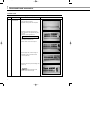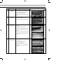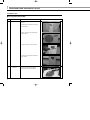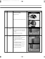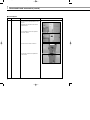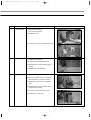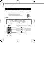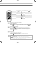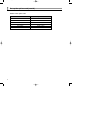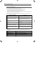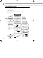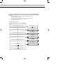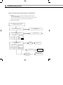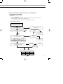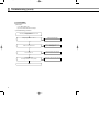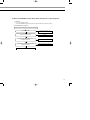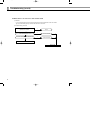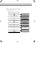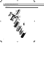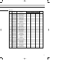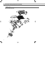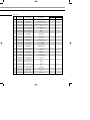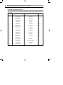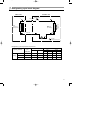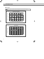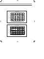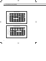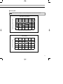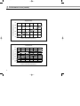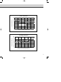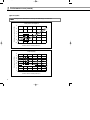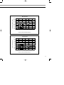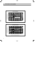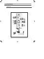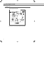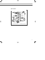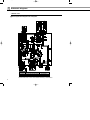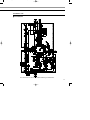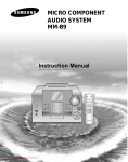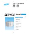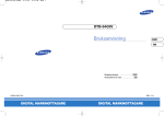
1
AS07AS(6)MA SM_E_15774
2/14/04 2:47 PM
Page 47
SERVICE
Manual
SPLIT TYPE AIR CONDITIONER
E DB98-15774A(2)
Indoor Unit
Outdoor Unit
AS07A5(6)MA
AS09A5(6)MAF
AS12AA(B)MCF
US07A5(6)MA
US09A5(6)MAF
US12AA(B)MCF
AS07AS(6)MA SM_E_15774
2/12/04 9:18 PM
Page 2
Safety Precautions
The following safety precautions must be taken when using your air conditioner.
WARNING
INSTALLING
THE UNIT
Risk of electric shock. • Can cause injury or death. • Disconnect all remote electric
power supplies before servicing, installing or cleaning. • This must be done by the
manufacturer or its service agent or a similar qualified person in order to avoid a
hazard.
◆ The unit should not be installed by the user. Ask the dealer or authorized
company to install the units except room air conditioners for the U.S.A and
Canada area.
◆ If the unit is installed improperly, water leakage, electric shock or fire may
result.
◆ The air conditioner must be installed in accordance with national wiring
regulations and safety regulations wherever applicable.
◆ Mount with the lowest moving parts at least 8.2ft(2.5m) above the floor or
grade level. (If applicable)
◆ The manufacturer does not assume responsibility for accidents or injury
caused by an incorrectly installed air conditioner. If you are unsure about
installation, contact an installation specialist.
◆ When installing the built-in type air conditioner, keep all electrical cables
such as the power cable and the connection cord in pipe, ducts, cable
channels e.t.c to protect them against liquids, outside impacts and so on.
POWER SUPPLY LINE,
FUSE OR CIRCUIT
BREAKER
◆ If the power cord of this air conditioner is damaged, it must be replaced by
the manufacturer, its service agent or similarly qualified persons in order to
avoid a hazard.
◆ The unit must be plugged into an independent circuit if applicable or
connect the power cable to the auxiliary circuit breaker. An all pole
disconnection from the power supply must be incorporated in the fixed
wiring with a contact opening of >3mm.
◆ Do not use an extension cord with this product.
◆ If the unit is equipped with a power supply cord and a plug, the plug must
be accessible after installation.
◆ This appliance must be installed accordance with the national wiring
regulations.
2
AS07AS(6)MA SM_E_15774
2/12/04 9:18 PM
Ι
Page 3
Contents
DISASSEMBLE AND REASSEMBLE
1. Indoor unit
2. Outdoor unit
ΙΙ
SET UP THE OPTION CODE
ΙΙΙ
4
6
10
TROUBLESHOOTING
ΙΛ
Λ
ΛΙ
ΛΙΙ
ΛΙΙΙ
1. Items to be checked first
2. Abnormal diagnosis by symptom
13
14
ASSEMBLY DRAWING AND PART’S LIST
1. Indoor unit
2. Outdoor unit
3. Assembly control in
4. Assembly control out
22
24
28
29
REFRIGERATING CYCLE BLOCK DIAGRAM
31
PERFORMANCE CURVE
32
WIRING DIAGRAMS
1. Indoor unit
2. Outdoor unit
41
42
SCHEMATIC DIAGRAMS
1. Indoor unit
2. Outdoor unit
44
45
SPLIT TYPE
AIR CONDITIONER
3
AS07AS(6)MA SM_E_15774
2/12/04 9:18 PM
Page 4
Ι
Disassemble and reassemble
Stop operation of the air conditioner and remove the power cable before repairing the unit.
1 Indoor unit
If you disassemble the heat exchanger, you must pump down at first.
No.
Part
Procedure
1
Front Panel
1) Stop the operation of the air conditioner
and block the main power.
2) Separate the tape from the front panel.
3) Contract the second finger to the left,
and right handle. And pull the inlet grille
to open.
4) Take the left and right filter out.
*Taking off the deodorizing filter.
5) Loosen one of the right screw and
separate the terminal cover.
6) Loosen three screws of front panel.
7) Pull the upper left, center and right of
discharge softly so that the outside
cover is pulled out.
8) Pull softly the lower part of discharge and
push it up.
Caution
Assemble the front panel and fix the
hooks of left, center and right.
4
Remark
AS07AS(6)MA SM_E_15774
2/12/04 9:19 PM
Page 5
No.
Part
Procedure
2
Electrical
Parts
(Main PCB)
1) Take all the connector of PCB
on the upper part. (Included Power cord)
Remark
2) Separate the outdoor unit connection
wire from the terminal block.
3) If you pull out the main PCB up, it will be
taken out.
3
Assembly Tray
Drain
1) Separate the drain hose from the
extension drain hose.
2) Pull tray drain out from the back body.
4
Heat
Exchanger
1) Loosen two ground screws at the
right side.
2) Separate the connection pipe.
3) Separate the holder pipe at the rear side.
4) Loosen three screws at the right and
left side.
5) Lift the heat exchanger up a little to push
the upper side to separate it from the
indoor unit.
5
Fan Motor and
Cross Fan
1) Loosen two screws and separate the
motor holder.
2) Loosen the screw of fan motor.
(By use of M3 wrench)
3) Separate the fan motor from the fan.
4) Separate the fan from the left holder
bearing.
5
AS07AS(6)MA SM_E_15774
2/12/04 9:19 PM
Page 6
Ι
Disassemble and reassemble (cont’d)
2 Outdoor unit
■ US07A5(6)MA/US09A5(6)MAF
No.
1
Part
Common Work
Procedure
1) Loosen screws and separate the cover
E-part.
2) Separate the connection wire from the
terminal block.
3) Loosen five screws and separate the
upper cabinet.
4) Loosen the screw of the control box.
5) Loosen nine screws and separate the
side cabinet.
2
6
Fan Motor
1) Loosen four screws and separate
Guard Fan from the front cabinet.
Remark
AS07AS(6)MA SM_E_15774
No.
2/17/04 4:38 PM
Part
Page 7
Procedure
Remark
2) Remove the nut flange
(Turn to the clockwise).
3) Separate the fan.
4) Loosen four screws to separate the motor.
3
Heat
Exchanger
1) Release the refrigerant.
2) Loosen two screws of left and right side.
3) Disassemble the inlet and outlet pipe by
welding.
4) Separate the heat exchanger.
4
Compressor
1) Release the refrigerant.
2) Loosen the nut on the terminal cover
and open the terminal cover.
3) Separate the OLP and the compressor
wire.
4) Disassemble the inlet and outlet pipe
of compressor by welding.
5) Disassemble the inlet and outlet pipe
of condenser by welding.
6) Loosen three bolts of the lower part.
7) Separate the compressor.
7
AS07AS(6)MA SM_E_15774
2/12/04 9:19 PM
Page 8
Ι
Disassemble and reassemble (cont’d)
■ US12AA(B)MCF
No.
Part
1
Common Work
Procedure
1) Loosen a screw and separate the cover
E-part.
2) Separate the connection wire from the
terminal block.
3) Loosen thirteen screws and separate
the front cabinet.
4) Loosen a screw of the control box.
5) Loosen four screws and separate the
side cabinet.
8
Remark
AS07AS(6)MA SM_E_15774
2/17/04 4:38 PM
No.
Part
2
Fan and Motor
Page 9
Procedure
Remark
1) Remove the nut flange
(Turn to the clockwise).
2) Separate the fan.
3) Loosen four screws to separate the motor.
4) Loosen five screws and separate the
motor bracket from the base.
3
Heat Exchanger
1) Release the refrigerant.
2) Loosen screws of left and right side.
3) Disassemble the inlet and outlet pipe by
welding.
4) Separate the heat exchanger.
4
Compressor
1) Release the refrigerant.
2) Open the terminal cover of compressor
and unscrew the connection terminal.
3) Separate the OLP and the compressor
wire.
4) Disassemble the inlet and outlet pipe of
compressor by welding.
5) Loosen three bolts of the lower part.
6) Separate the compressor.
9
AS07AS(6)MA SM_E_15774
2/12/04 9:19 PM
Page 10
ΙΙ
Set up the option code
The method for setting up the model option with the remote control
◆ It is necessary to set up option codes after replacing the main PCB with service parts.
Make sure that you can set up option codes of the remote control after replacing the main PBA.
Otherwise, the unit won’t be working properly and all LED lamps on display will be flickering.
Step 1
Preparing for the remote control to the main PCB option set.
1. Remove the battery from the remote control.
2. Press the temperature button simultaneously and insert the battery again.
3. Make sure the remote control display shown as
.
Step 2
Note
Preparing for the remote control option set.
In case that the wrong letter has been selected; continue to press the button until the
correct letter appears.
1. If the number “
2. Every time you
3. Every time you
from ~ ( ,
”appears on the display, proceed to the second stage.
press the 1) and 7) button, “ ” and “ ” continue to appear.
press the 2), 3), 4), 5), 6), 8), 9), 10), 11), 12) button, the number increases
, , , , , , , , ) and , , , , , in order.
1) If the first number is
until appears.
10
, it is correct. Otherwise, press the
button
2) When pressing the
button
~
on the display, select one of them.
3) When pressing the
button
~
on the display, select one of them.
4) When pressing the
button
~
on the display, select one of them.
5) When pressing the
button
~
on the display, select one of them.
6) When pressing the
button
~
on the display, select one of them.
AS07AS(6)MA SM_E_15774
2/12/04 9:19 PM
Page 11
7) If the first number is , it is correct. Otherwise, press the
until appears.
Step 3
button
8) When pressing the
button
~
on the display, select one of them.
9) When pressing the
button
~
on the display, select one of them.
10) When pressing the
button
~
on the display, select one of them.
11) When pressing the
button
~
on the display, select one of them.
12) When pressing the
button
~
on the display, select one of them.
Reconfirming the option set after completing
Example : 000000-1700b7
Press the
button for the “ ” mode and the display will be shown as
Press the
button for the “ ” mode and the display will be shown as
Step 4
Pressing the
.
.
(On/Off) button
When pressing the
(On/Off)button in the direction of the remote control for unit,
it sounds beep or ringing and the first LED lamp on the left side is flickering at the
same time, then the input option is completed. If it doesn’t sound ringing, try again by
pressing the
(On/Off)button.
Step 5
Testing the unit
1 Remove the battery from the remote control.
2. Insert the battery into the remote control.
3. Press the
(On/Off)button in the direction of the remote control for set.
Note
Error mode
1. If all lamps of the indoor units are flickering, plug out and in again and press the
(On/Off) button again.
2. If the unit doesn’t work properly or all lamps are continuously flickering after setting the option
code, check that the option code is set properly for its own model.
11
AS07AS(6)MA SM_E_15774
2/12/04 9:19 PM
Page 12
ΙΙ
Set up the option code (cont’d)
A table of the option code
12
Model
Option code
AS07A5MA
010000-1700b7
AS07A6MA
000000-1700b7
AS09A5MAF
010000-1700Fb
AS09A6MAF
000000-1700Fb
AS12AAMCF
010000-170340
AS12ABMCF
000000-170340
AS07AS(6)MA SM_E_15774
2/12/04 9:19 PM
Page 13
ΙΙΙ
Troubleshooting
1 Items to be checked first
1) The input voltage should be voltage rating within ±10% range.
The air conditioner may not operate properly if the voltage is out of this range.
2) Is the connection cable linking the indoor unit and the outdoor unit properly?
The indoor unit and the outdoor unit shall be linked by five cables.
Check the terminals if the indoor unit and outdoor unit are properly linked by the same number of cables.
Otherwise the air conditioner may not operate properly.
3) When a problem occurs due to the contents illustrated in the table below, it is not a symptom related
to the malfunction of the air conditioner.
No.
Operation of air conditioner
Explanation
1
The STD operation indicator, LED blinks when a
power plug of the indoor unit is plugged in at first.
It indicates power is on. The LED stops blinking if the
On/Off button on the remote control is pushed.
2
In the Cool mode, the compressor does not operate
at a room temperature higher than the setting
temperature while the indoor fan operates.
It happens after three minutes when the compressor is
reoperated. The same phenomenon occurs when a power
is on. As a phenomenon that the compressor is
reoperated after three minutes, the indoor fan is adjusted
automatically with reference to a temperature of the air.
3
The Fan speed operating is not allowed in the Auto
or Dry mode.
The speed of the indoor fan is set to LL in the Dry mode.
The Fan speed is five steps are selected automatically in
the Auto mode.
Compressor stops operating intermittently in the Dry
mode.
The compressor is controlled automatically in the Dry
mode depending on the room temperature and humidity.
Timer LED of the indoor unit lights up
and the air conditioner does not operate.
The timer is being activated and the unit is in the ready
mode. The unit operates normally if the timer operation is
cancelled.
The compressor stops intermittently in the Cool or
Dry mode, and the fan speed of the indoor unit
decreases.
The compressor stops intermittently or the fan speed of the
indoor unit decreases to prevent inside/outside air from
freezing depending on the inside/outside air temperature.
4
5
6
4) Indoor unit observes operation condition of the air conditioner and displays self diagnosis on the
display panel.
No.
Display
Self Diagnosis
1
STD LED blinking (1Hz)
Restore from power failure (input initial power)
2
TIMER LED blinking (1Hz)
Indoor unit Room sensor Error (open or short)
3
STD and TIMER LED blinking (1Hz)
Indoor unit heat exchanger temperature sensor Error (open or short)
4
NATURE LED blinking (1Hz)
Indoor fan malfunctioning (for speed is below 450rpm)
5
All LED blinking (1Hz)
Option Error
13
AS07AS(6)MA SM_E_15774
2/12/04 9:19 PM
Page 14
ΙΙΙ
Troubleshooting (cont’d)
2 Abnormal diagnosis by symptom
1. No Power - Initial diagnosis
1) Checklist :
(1) Is input voltage normal?
(2) Is AC power linked correctly?
(3) Is output voltage of DC regulator IC KA78L05 (IC02) normal? (4.5VDC-5.5VDC)
2) Troubleshooting procedure
Remove the power cord and plug in
again in approx. five seconds
Does the lamp blink?
NO
YES
Replace PCB
display
YES
Does it start operating when
you push the On/Off button
on the remote control?
NO
Is transmission display of the
remote control unit blinking?
Is DC voltage of PCB
display normal?
NO
Is voltage rating within ±10%
range applied to the primary
side(~,~) of the “BD71”?
NO
NO
Normal
NO
Refer to remote control
unit abnormal diagnosis
NO
Replace PCB
module.
YES
Does the ‘beep’ sound from the
main unit?
YES
Is DC voltage of the PCB module
normal?
Check linkage between
a power cord and
a terminal tap
Check fuse
YES
Are voltages of #33 (IC04 : compressor)
of Micom normal? 5VDC
Is voltage of #32 (IC04 : indoor fan) of
Micom normal?
Does 325VDC appear in
the secondary side (+, -)
of “BD71”?
NO
YES
YES
Are voltages of RY71(Compressor)
normal? DC12V
Is voltage of SS71(indoor fan)?
DC5V
10ms
YES
YES
NO
Is voltage of #10(IC04) terminal of Micom normal?
0VDC
Is voltage of #9(IC04) terminal of Micom normal?
5VDC
Replace
SMPS PARTS
Check connections
of compressor
and indoor fan.
Replace
RY71 and
SS71
NO
YES
Is output voltage of ICO2 normal?
Is voltage of #3(IC04) terminal of
Micom normal?
YES
NO
YES
Check PCB pattern
Replace the main PCB
10ms
NO
NO
Replace ICO2
NO
Are voltages of #12(IC04) and
#11(IC04) of Micom normal?
Is voltage output terminal of
PC814A(PC02) normal?
YES
Replace resonator (X301)
NO
250ns
YES
Is operation normal?
YES
14
OK
NO
Replace
Micom
OK
Replace PC814A(PC02)
AS07AS(6)MA SM_E_15774
2/12/04 9:19 PM
Page 15
1-1 No Power-Initial diagnosis in case of the Outdoor Unit PCB of US12AA(B)MCF
1) Checklist :
(1) Is AC voltage between “L1” and “1” of outdoor terminal block is normal?
(Input voltage within ±10% range)
If the Output is not checked, check “L1” and “1” of Indoor Terminal Block.
(2) Are connectors linked correctly to the outdoor PCB?
(CN71, CN76, CN72, CN11)
2) Troubleshooting procedure
Check AC Output between “L1” and “1” of the outdoor terminal block
Is voltage rating between #1 and #3 (CN72) normal?
NO
Replace PCB
YES
Is AC voltage between #1 and #3 (CN11) ( =: )AC 17V?
NO
NO
NO
NO
YES
Is LED 01 (GRN) on?
IC01(KA7812) is abnormal.
Replace PCB
YES
Is DC voltage between “G” and “O” (IC02) ( =: ) DC 5V?
BD71 or D101 is abnormal.
Replace PCB
YES
Is DC voltage between “G” and “O” (IC01) ( =: ) DC 12V?
TRANS is abnormal.
Replace TRANS
YES
Is DC voltage between “I” and “G” (IC01) normal?
Check F701, F702 is open
IC02 is abnormal.
Replace PCB
NO
MICOM or LED is abnormal.
YES
Is the power supply normal?
Check the other connection parts
15
AS07AS(6)MA SM_E_15774
2/12/04 9:19 PM
Page 16
ΙΙΙ
Troubleshooting (cont’d)
2. When the Indoor Unit Fan Does Not Operate - Initial Diagnosis
1) Checklist :
(1)
(2)
(3)
(4)
Is
Is
Is
Is
the indoor unit fan motor properly connected with the connector (CN72)?
the AC voltage correct?
HALL IC in the indoor fan motor properly connected with the connector (CN42)?
the running capacitor (CR71) properly connected with PCB board?
2) Troubleshooting procedure
After unplugging out, the power cord should
be reconnected within five seconds.
YES
NO
Check as the procedure “No power”
Refer to page 14
Does the STD lamp(Green) blink?
YES
Does the Solid State Relay(SS71) work
properly?
NO
Micom is abnormal
Test rod location
+
-
SS71-
SS71-
Normal
Voltage
12V
YES
Is the supply voltage of the fan
motor sufficient?
NO
PCB is
abnormal
Replace PCB
Test rod location
PCB CN72
Condition
pin #3 and #5
Fan operate
Normal
voltage
about AC
180V
MFC is abnormal
Replace MFC
YES
Fan motor
is abnormal.
16
Replace Fan motor
AS07AS(6)MA SM_E_15774
2/12/04 9:19 PM
Page 17
3. When the Outdoor Unit Does Not Operate - Initial Diagnosis
3-1 US07A5(6)MA / US09A5(6)MAF
1) Checklist :
(1)
(2)
(3)
(4)
Is
Is
Is
Is
input voltage normal?
the set temperature of the remote control higher than room temperature in the Cool mode?
the POWER IN connector (CN71) linked correctly?
the outdoor unit properly connected with the terminal block connector?
2) Troubleshooting procedure
After unplugging out, the power cord
should be reconnected within five seconds.
NO
Does the STD lamp blink?
Check as the procedure "No Power"
Refer to page 14
YES
YES
Does the timer lamp blink during operation ?
1
Room temperature sensor is
abnormal.
NO
3
2
Test rod location
Micom is
abnormal.
NO
Is the power relay RY71 operated by adjusting
the room temperature?
Check PCB
Normal
+
-
Condition
Voltage
#33(IC04)
GND
RY71 ON
DC 4.8V
Check PCB
NO
Is voltage rating within ±10% range applied relay
between the terminal block?
NO
Replace the
Power relay
Power relay
is abnormal.
YES
Outdoor unit is
abnormal.
1
YES
NO
2
Is the room sensor registered normal?
50°F(10°C)
68°F(20°C)
86°F(30°C)
17.96k Ω
12.09k Ω
8.3k Ω
YES
3
17
AS07AS(6)MA SM_E_15774
2/12/04 9:19 PM
Page 18
ΙΙΙ
Troubleshooting (cont’d)
3-2 US12AA(B)MCF
1) Checklist :
(1) Is LED 01(GRN) on?
(2) Are all connectors linked correctly?
2) Troubleshooting procedure
Check the power supply between “L1” and “L2” of the
outdoor terminal block
Is voltage rating between “L1” and “1” ?
NO
Check the indoor PCB again
YES
Is LED 01 of the indoor PCB on?
NO
Check the connection wire and No Power
Refer to page 14
YES
Is the compressor on?
NO
Check the compressor lead wire again
YES
Is the Outdoor fan on?
Is AC voltage between “L1” and “1” (CN76)?
YES
Normal
18
NO
Check the indoor PCB and connection wire again
AS07AS(6)MA SM_E_15774
2/12/04 9:19 PM
Page 19
4. When the UP/DOWN Louver Motor Does Not Operate - Initial Diagnosis
1) Checklist :
(1) Is input voltage normal?
(2) Is the UP/DOWN louver motor properly connected with the connector (CN61)?
2) Troubleshooting procedure
Remove the power cord and plug it in again in approx. five seconds
Does STD lamp blink?
NO
YES
Does it start operating when you push the swing
button of the remote control?
Check as the procedure "No
Power". Refer to page 14
YES
Normal
NO
Is voltage of #58 ~ #61 of Micom (ICO4)
changed?(Squarewave)
NO
Micom (IC04) is abnormal.
YES
Is voltage of #13 ~ #16 of IC06 (ULN2003A)
changed?(Squarewave)
NO
Driver IC06 (ULN2003A) is abnormal.
YES
The UP/DOWN louver motor is abnormal.
19
AS07AS(6)MA SM_E_15774
2/12/04 9:19 PM
Page 20
ΙΙΙ
Troubleshooting (cont’d)
5. When there is no cool air in the current mode
1) Checklist :
(1) Is the set temperature of the remote control lower than room temperature in the Cool mode?
(2) Is the Indoor PCB properly connected with the CN71 connector?
2) Troubleshooting procedure
After training on, the Cooling starts
operating in five minutes.
YES
Normal
NO
Is #9 of Micom (IC04) DC 5.0 V?
NO
Micom is abnormal.
YES
Is the number checking #10 of IC06 (ULN2003A) LOW?
NO
IC 06 is abnormal.
RY71 or check cable
Replace PCB
20
AS07AS(6)MA SM_E_15774
2/12/04 9:19 PM
Page 21
6. When the remote control does not operate
1) Troubleshooting procedure
Remove the power cord and plug it in again approx. five Seconds
Does STD lamp blink?
NO
YES
The melody sounds from the indoor unit when you
push the On/Off button on the remote control.
YES
Check as the procedure “No Power”
Refer to page14
Normal
NO
Is voltage of battery less than 2.5V (Remote Control Unit)?
YES
Replace the battery
NO
Is LCD display status of the remote control normal?
NO
LCD is abnormal.
YES
Does the transmission indicator in the display blink
when you push the On/Off button on the remote control?
NO
Replace button
YES
Is voltage of #15(IC04) of remote control of Micom changed?
NO
Micom is abnormal.
YES
Is voltage at collector of Q601 or Q602 changed?
NO
Q601(2SC2412K) or Q602(2SC2412K)
is abnormal. IR LED(CL-1L5EU) is
abnormal.
YES
Is voltage of #20 of Micom (IC04) changed (Indoor unit)?
YES
Receiver module is abnormal.
NO
Micom (IC04) is abnormal.
21
AS07AS(6)MA SM_E_15774
2/12/04 9:19 PM
Page 22
ΙΛ
Assembly drawing and part’s list
1 Indoor unit
18
18-6
18-6-1
18-1
18-4
18-5
18-3
24
16
18-2
17
13
13-2 13-4
13-3
13-1
14
15
11
12
10
8
20
25
22
23
19
9
6
5
7
4
21
3
2
1
22
AS07AS(6)MA SM_E_15774
■
2/12/04 9:19 PM
Page 23
Part’s List
No.
Code No.
Description
1
2
3
4
5
6
7
8
9
10
11
DB64-00085A
DB63-00064B
DB95-00287K
DB63-00067A
DB92-00031L
DB67-00051A
DB67-00032A
DB63-00083A
DB94-00020D
DB60-20011A
DB31-00071A
DB31-00071B
DB32-00020A
DB93-00458B
DB93-00458H
DB93-01018B
DB93-01018A
DB65-00079B
DB93-00268A
DB39-00147A
DB94-00377C
DB94-00377D
DB61-00162A
DB61-00165A
DB70-00214A
DB94-00376A
DB94-00062E
DB66-00127B
DB66-00128A
DB66-00128B
DB63-00082A
DB95-20138A
DB31-10129A
DB61-40251A
DB67-60030A
DB96-01247B
DB96-01443A
DB94-40003A
DB93-00861A
DB70-00114A
DB63-00226A
GRILLE-AIR INLET
GUARD-AIR FILTER
FILTER CLEANER ASS´Y
COVER TERMINAL
ASS´Y PANEL-FRONT
SPACER EVAP LOW
SPACER EVAP UP
COVER U BEND
ASS´Y CROSS FAN
BOLT SPECIAL
MOTOR FAN IN
MOTOR FAN IN
THERMISTOR WIRE ASS´Y
ASS´Y CONTROL IN
ASS´Y CONTROL IN
ASS´Y PCB MAIN
ASS´Y PCB MAIN
TERMINAL BLOCK ASS´Y
ASS´Y PCB DISPLAY
CONNECT WIRE PCB
ASS´Y BACK BODY
ASS´Y BACK BODY
HOLDER MOTOR
HOLDER PIPE
PLATE HANGER
ASS´Y TRAY DRAIN
ASS´Y DRAIN HOSE
BLADE H
BLADE V,A
BLADE V,B
SCREEN SAFETY WIRE
ASS´Y MOTOR STEPPING
MOTOR STEPPING
HOLDER SENSOR
SPRING SENSOR
ASS’Y CYCLE IN
ASS’Y CYCLE IN
RUBBER BEARING
ASS´Y REMOCON
PLATE-KNOCKOUT
COVER TERMINAL BLOCK
12
13
13-1
13-2
13-3
13-4
14
15
16
17
18
18-1
18-2
18-3
18-4
18-5
18-6
18-6-1
19
20
21
22
23
24
25
Q’TY
AS07A5(6)MA AS09A5(6)MAF AS12AA(B)MCF
1
1
1
1
1
1
1
1
1
1
1
1
1
1
1
1
1
1
1
1
1
1
1
1
1
1
1
1
1
1
1
1
1
1
1
1
1
1
1
1
1
1
1
1
1
1
1
1
1
1
1
1
1
1
1
1
1
1
1
1
1
1
1
1
1
1
1
1
1
1
1
1
Remark
1
1
1
1
1
1
1
1
1
1
1
1
1
1
1
1
1
1
1
1
1
1
1
1
1
1
1
1
1
1
1
1
1
1
1
1
23
AS07AS(6)MA SM_E_15774
2/12/04 9:19 PM
Page 24
ΙΛ
Assembly drawing and part’s list (cont’d)
2 Outdoor unit
■ US07A5(6)MA/US09A5(6)MAF
22
23
20
21
7
17
6
8
9
-1
12
4
5
24
2
18
19
3
8-
1
-1
10
16
2
8-
3
17
13
15 11
14
4
8- 1
8-
18
AS07AS(6)MA SM_E_15774
■
2/12/04 9:19 PM
Page 25
Part’s List
Q’TY
No.
Code No.
1
2
Description
Specification
DB63-00086B
GUARD-FAN
HSWR, IP2, 5&3, SC-90073T,375FAN
1
1
DB60-30004A
NUT-FLANGE
2C, M6, SM20C, NTR
1
1
3
DB67-00036A
FAN-PROPELLER
AS+G/F20%, PI 375, BLK
1
1
4
DB31-10058G
MOTOR-FAN OUT
ASS020ZREA, FAN OUT,115V/60Hz
1
1
5
DB90-00264G
ASS´Y FRAME (PAINT)
ASS’Y
1
1
6
DB94-00078A
ASS´Y PARTITION
ASS´Y 620mm COND
1
1
7
DB90-00077B
ASS´Y CABI-UPPER
ASS´Y
1
1
8
DB93-00424Q
ASS´Y CONTROL OUT
ASS´Y
1
-
DB93-00424R
ASS´Y CONTROL OUT
ASS´Y
-
1
2501-001226
C-OIL (COMP)
25µF, 370VAC
1
-
2501-001230
C-OIL (COMP)
45µF, 370VAC
-
1
8-2
2301-001379
C-OIL (MOTOR)
4.0µF, 450VAC
1
1
8-3
DB33-00423A
ASS´Y LEAD WIRE
V2 P/D (105˚C)
1
1
8-4
DB65-40074B
TERMINAL BLOCK
5P, L1, L2, 1, 2, 3
1
1
9
DB72-00453A
CLOTH-COMP
T8, 425, 225, 44F COMP
1
1
10
44A072HW1EB
ROTARY COMP
1Ph, 115V/60Hz
1
-
8-1
US07A5(6)MA US09A5(6)MAF
44B098HX1EF
ROTARY COMP
1Ph, 115V/60Hz
-
1
DB47-20001V
PROTECTOR O/L
MRA98706-12008
1
-
DB35-00011D
PROTECTOR O/L
MRA12132-12007
-
1
12
DB73-00070A
GROMMET-ISOLATOR
NR
3
3
13
DB60-30018A
NUT-FLANGE
PI0.8, M5, SM20C
1
1
14
DB63-20002A
GASKET
EPDM, TO.8
1
1
15
DB63-10165D
COVER-TERMINAL
PBT
1
1
16
DB60-30028A
NUT-WASHER
HEX, 2C, M8, ZPC
3
3
17
DB96-00553B
ASS´Y TUBE CAPILLARY
ID1.42 x 800+1/4 inch
1
-
DB96-00553A
ASS´Y TUBE CAPILLARY
ID1.5 x 900+1/4 inch
-
1
17-1
DB62-00254B
VALVE-SERVICE
1/4 inch
1
1
18
DB96-00615A
ASS’Y TUBE SUCTION
ASS´Y
1
-
11
DB96-03291A
ASS´Y TUBE -SUCTION
ASS´Y
-
1
18-1
DB62-40073B
VALVE-SERVICE
3/8 inch
1
1
19
DB96-00616A
ASS´Y TUBE DISCHARGE
ASS´Y
1
-
DB96-03290A
ASS´Y TUBE -DISCHARGE
ASS´Y
-
1
20
DB96-01911A
ASS´Y COND
1.7D-FIN, 620mm
1
1
21
DB64-60171D
CABINET-SIDE
SECC-P, T 0.8
1
1
22
DB67-00091A
HANDLE-CABI LF
PP
1
1
23
DB63-10443C
COVER-E, PARTS ASS’Y
SC-90073R
1
1
25
AS07AS(6)MA SM_E_15774
2/12/04 9:19 PM
Page 26
ΙΛ
24
Assembly drawing and part’s list (cont’d)
25
1
21
5
12
0
2
3
6
4
1
8
7
8-
4
8-
8-
9
7
13
8-
14
8 8
-1
8-
8-
12
3
8-
14
8-
2
8-
8-
11
8-
13
8-
6
15
9
8-
5
16
23
17
10
11
19
18
22
20
■ US12AA(B)MCF
26
AS07AS(6)MA SM_E_15774
■
2/12/04 9:19 PM
Page 27
Part’s List
No.
Code No.
Description
Specification
1
DB63-00385B
GUARD FAN
HSWR,OD 2.0
1
2
DB60-30020A
NUT-FLANGE
2C SM20C M6 NTR
1
3
DB67-50063A
FAN-PROPELLER
AS+G/F, D405
1
4
DB31-00242A
MOTOR-FAN OUT
220/240V,60/50HZ
1
5
DB90-00633N
ASS'Y CABI-FRONT
ASS'Y
1
6
DB90-00687D
ASS'Y BASE OUT
ASS'Y
1
7
DB61-00887A
BRACKET-VALVE
SECC-P
1
8
DB93-02588A
ASS'Y CONTROL OUT
ASS'Y
1
8-1
2501-001237
CAPACITOR COMP
35uF 450VAC
1
8-2
2301-001375
CAPACITOR MOTOR
1.5uF 450VAC
1
8-3
DB65-40074B
TERMINAL-BLOCK
5P DFT-20A
1
8-4
DB93-00423B
ASS'Y LEAD WIRE
ASS'Y
1
8-5
DB35-00015H
OLP
RAC12074-9622
1
8-6
DB67-60020A
SPRING OLP
STS304
1
8-7
DB93-02618B
ASS’Y CONNECT WIRE
ASS'Y
1
8-8
DB32-00007A
THERMOSTAT-ASS'Y
ASS'Y
1
8-9
DB39-00530A
CONNECT WIRE-THERMOSTAT, B
ASS'Y
1
8-10
DB39-20290H
CONNECT WIRE-THERMOSTAT A
AWM1015 AWG#18
1
8-11
DB61-01769A
HOLDER PCB
ABS
1
8-12
DB93-02576A
ASS’Y MAIN PCB OUT
ASS'Y
1
8-13
DB26-10063B
TRANS POWER
-
1
8-14
DB32-10051H
THERMISTOR-ASS’Y
2P, 103AT/DKS-103HW
1
9
DB94-00163C
ASS’Y PARTITION
ASS'Y
1
10
DB96-03140A
ASS’Y TUBE-SUCTION
ASS'Y
1
11
DB62-01249A
TUBE DISCHARGE
ASS'Y
1
12
48D135IU1EL
COMPRESSOR
208-230V/60H
1
13
DB73-00067A
GROMMET ISOLATOR
NR
3
14
DB60-30028A
NUT-WASHER
HEX 2C MB ZPC
3
15
DB63-20002A
GASKET
EPDM
1
16
DB63-10165D
COVER TERMINAL
PBT
1
17
DB60-30018A
NUT-FLANGE
M5,SM20C
1
18
DB96-01457J
ASS’Y TUBE CAPILLARY
ASS'Y
1
19
DB96-01533A
ASS’Y COND-UNIT
ASS'Y
1
20
DB90-00634B
ASS’Y CABI-SIDE
ASS'Y
1
21
DB61-00802A
BRACKET MOTOR
SGCC-M
1
22
DB63-10443C
COVER-E,PARTS ASS’Y
ABS
1
23
DB63-00893A
CLOTH COMP SIDE
T10,580,255
1
24
DB61-40251A
HOLDER SENSOR
PP
1
25
DB95-00212B
ASS'Y HEATER
ASS'Y
1
Q’TY
Remark
27
AS07AS(6)MA SM_E_15774
2/12/04 9:19 PM
Page 28
ΙΛ
Assembly drawing and part’s list (cont’d)
3 Assembly control in
■ AS07A5(6)MA/AS09A5(6)MAF/AS12AA(B)MCF
■
Part’s List
No.
Description
1
HOLDER CONTROL
ASS’Y MAIN PCB
ASS’Y TERMINAL BLOCK
ASS’Y DISPLAY PCB
CONNECTOR WIRE PCB U/D
SCREW
HOLDER CLAMP IN
SEAL - PANEL FRONT RH
SEAL - H/CONTROL FRONT
LABEL
ASS’Y THERMISTOR
2
3
4
5
6
7
8
9
10
11
28
Code No.
AS07A5(6)MA / AS09A5(6)MAF AS12AA(B)MCF
DB61-00160B
DB93-01018B
DB65-00079B
DB93-00268A
DB39-00147A
DB61-00219B
DB72-10191T
DB62-02664A
DB68-01975A
DB32-00020A
DB61-00160B
DB93-01018A
DB65-00079B
DB93-00268A
DB39-00147A
DB61-00219B
DB72-10191T
DB62-02664A
DB68-01975A
DB32-00020A
Remark
SNA
SNA
SNA
SNA
-
AS07AS(6)MA SM_E_15774
2/12/04 9:19 PM
Page 29
4 Assembly control out
■ US12AA(B)MCF
29
AS07AS(6)MA SM_E_15774
2/12/04 9:19 PM
Page 30
ΙΛ
Assembly drawing and part’s list (cont’d)
4 Assembly control out (cont’d)
■
30
Part’s List
No.
Description
Specification
Remark
1
PLATE-CONTROL OUT
SGCC-M T0.6
-
3
C-OIL (CAPACITOR)
35uF/450VAC
-
4
CLIP-CAPACITOR
SGCC-MØ50
-
5
SCREW-TAPPING
2S-M4 x L10
SNA
6
C-OIL(CAPACITOR)
1.5uF/450VAC
-
7
TERMINAL-BLOCK
300V, 20A 5P
-
8
HOLDER PCB
ABS, BLK
-
9
HOLDER-WIRE
NYLON(BLK)
-
10
SCREW-TATITE
FH, M4 x L12
SNA
11
SCREW-TAPPING
TH, M4 x L16, ZPC(YEL)
SNA
12
SCREW-SPECIAL
M4 x 8
SNA
13
ASS’Y-LEAD, WIRE
ASS’Y
-
14
SPRING-O.L.P
STS304-WPA
-
15
O.L.P
RAC12074-9622
-
16
LEAD-WIRE C
SILICON GLASS
-
17
SCREW-TAPPING
PH, M4 x 25
SNA
18
LABEL-CAUTION
50 x 12
SNA
19
THERMOSTAT
PW-2N, ON/OFF:4/15
-
20
CONNECT-WIRE
WIRE ASS’Y
-
21
CONNECT-WIRE
WIRE
-
22
SCREW-TAPPING
PH, 2S, M3 x 8
SNA
23
TRANS
-
-
24
CONNECT-WIRE
ASS’Y
-
25
ASS’Y THERMISTOR
AWH126JE
-
26
SCREW-TAPPING
TH, +, 2S, M3 x 8
SNA
27
HOLDER WIRE
SGCC-M+PVC COATING
-
28
CLAMP WIRE
DAWH-5NB
-
29
CABEL-CLAMP
NYLON 66 / 3N
-
30
ASS’Y PCB MAIN OUT
ASS’Y
-
AS07AS(6)MA SM_E_15774
2/12/04 9:19 PM
Page 31
Λ
Refrigerating cycle block diagram
Indoor unit
Outdoor unit
Capillary tube
T1
2-way valve
Heat
exchanger
(Evaporator)
Propeller fan
Cross fan
Liquid side
Heat
exchanger
(Condenser)
T2
Gas side
3-way valve
Cooling
Compressor
Gas leak check point
Refrigerating cycle temperature and pressure
STD Pressure
Operating Condition
Use Temp. Condition [°F(°C )]
Outdoor
Indoor
(psi)
3-Way Valve
Cooling
Piping Temp.[°F(°C )]
T1
T2
DB
WB
DB
WB
Standard
71~81
50~54(10~12) 50~54(10~12)
80(27)
67(19)
95(35)
75(24)
Max over load
-
60~64(16~18) 60~64(16~18)
80(27)
67(19)
115(46)
75(24)
Low temp
55~56
67(19)
57(14)
67(19)
57(14)
34~39(1~4)
34~39(1~4)
31
AS07AS(6)MA SM_E_15774
2/12/04 9:19 PM
Page 32
ΛΙ
Performance curve
■ AS07A5(6)MA
N o t e Data is based on condition of indoor humidity 50%. Air flow should be set at HI.
Total power consumption
Total power consumption (x10 3kW)
1.0
71
67
63
59
0.9
Indoor intake air WB temperature(°F)
0.8
0.7
0.6
0.5
0.4
55
65
75
85
95
105
115
Outdoor intake air DB temperature(°F)
Total capacity
8
Total capacity (x10 3Btu/h)
7
71
67
63
55
6
5
Indoor intake air WB temperature(°F)
4
3
2
1
0
55
65
75
85
95
105
Outdoor intake air DB temperature(°F)
32
115
2/12/04 9:19 PM
Page 33
High pressure
Condensing pressure (psi.G)
390
86
80
75
70
340
Indoor DB temperature(°F)
290
240
190
140
55
65
75
85
95
105
115
Outdoor ambient DB temperature(°F)
Low pressure
90
85
Suction pressure (psi.G)
AS07AS(6)MA SM_E_15774
86
80
80
75
Indoor DB temperature(°F)
75
70
70
65
60
55
50
45
40
55
65
75
85
95
105
115
Outdoor ambient DB temperature(°F)
33
AS07AS(6)MA SM_E_15774
2/12/04 9:19 PM
Page 34
ΛΙ
Performance curve (cont’d)
Suction temperature
80
Suction temperature (°F)
70
86
60
80
50
75
70
40
30
Indoor DB temperature (°F)
20
10
0
55
65
75
85
95
105
115
Outdoor ambient DB temperature (°F)
Discharge temperature
Discharge temperature (°F)
240
86
80
75
70
220
200
180
Indoor DB temperature(°F)
160
140
120
100
55
65
75
85
95
Outdoor ambient DB temperature (°F)
34
105
115
AS07AS(6)MA SM_E_15774
2/12/04 9:19 PM
Page 35
■ AS09A5(6)MAF
N o t e Data is based on condition of indoor humidity 50%. Air flow should be set at HI.
Total power consumption
Total power consumption (x10 3kW)
1.3
71
67
63
59
1.2
1.1
Indoor intake air WB temperature(°F)
1.0
0.9
0.8
0.7
0.6
55
65
75
85
95
105
115
Outdoor intake air DB temperature(°F)
Total capacity
Total capacity (x10 3Btu/h)
12
10
8
71
67
63
55
Indoor intake air WB temperature(°F)
6
4
2
0
55
65
75
85
95
105
115
Outdoor intake air DB temperature(°F)
35
AS07AS(6)MA SM_E_15774
2/12/04 9:19 PM
Page 36
ΛΙ
Performance curve (cont’d)
High pressure
Condensing pressure (psi.G)
390
86
80
75
70
340
Indoor DB temperature(°F)
290
240
190
140
55
65
75
85
95
105
115
Outdoor ambient DB temperature(°F)
Low pressure
90
Suction pressure (psi.G)
85
86
80
80
75
Indoor DB temperature(°F)
75
70
70
65
60
55
50
45
40
55
65
75
85
95
Outdoor ambient DB temperature(°F)
36
105
115
2/12/04 9:19 PM
Page 37
Suction temperature
80
Suction temperature (°F)
70
86
60
80
50
75
70
40
30
Indoor DB temperature(°F)
20
10
0
55
65
75
85
95
105
115
Outdoor ambient DB temperature (°F)
Discharge temperature
240
Discharge temperature (°F)
AS07AS(6)MA SM_E_15774
86
80
75
70
220
200
180
Indoor DB temperature(°F)
160
140
120
100
55
65
75
85
95
105
115
Outdoor ambient DB temperature (°F)
37
AS07AS(6)MA SM_E_15774
2/12/04 9:19 PM
Page 38
ΛΙ
Performance curve (cont’d)
■ AS12AA(B)MCF
N o t e Changes in the dotted box are caused by the RPM change of outdoor fan.
Total power consumption
Total power consumption (x10 3kW)
1.5
71
67
63
59
1.4
1.3
Indoor intake air WB temperature(°F)
1.2
1.1
1.0
0.9
55
65
75
85
95
105
115
Outdoor intake air DB temperature(°F)
Total capacity
16
Total capacity (x10 3Btu/h)
15
14
13
12
71
11
67
10
Indoor intake air WB temperature(°F)
63
9
59
8
7
6
55
65
75
85
95
Outdoor intake air DB temperature(°F)
38
105
115
2/12/04 9:19 PM
Page 39
High pressure
Condensing pressure (psi.G)
350
86
80
75
70
330
310
290
Indoor DB temperature(°F)
270
250
230
210
190
170
55
65
75
85
95
105
115
Outdoor ambient DB temperature(°F)
Low pressure
100
95
Suction pressure (psi.G)
AS07AS(6)MA SM_E_15774
90
85
80
75
86
Indoor DB temperature(°F)
80
70
75
70
65
60
55
50
55
65
75
85
95
105
115
Outdoor ambient DB temperature(°F)
39
AS07AS(6)MA SM_E_15774
2/12/04 9:19 PM
Page 40
ΛΙ
Performance curve (cont’d)
Suction temperature
80
Suction temperature (°F)
70
86
60
80
50
75
40
70
30
Indoor DB temperature(°F)
20
10
0
55
65
75
85
95
105
115
Outdoor ambient DB temperature(°F)
Discharge temperature
230
Discharge temperature (°F)
220
210
86
80
75
70
Indoor DB temperature(°F)
200
190
180
170
160
150
140
55
65
75
85
95
Outdoor ambient DB temperature(°F)
40
105
115
AS07AS(6)MA SM_E_15774
2/12/04 9:22 PM
Page 41
ΛΙΙ
Wiring diagrams
1 Indoor unit
■ AS07A5(6)MA/AS09A5(6)MAF/AS12AA(B)MCF
This document can not be used without Samsung’s authorization.
41
AS07AS(6)MA SM_E_15774
2/12/04 9:22 PM
Page 42
ΛΙΙ
Wiring diagrams (cont’d)
2 Outdoor unit
■ US07A5(6)MA/US09A5(6)MAF
DIAGRAM
This document can not be used without Samsung’s authorization.
42
AS07AS(6)MA SM_E_15774
2/12/04 9:24 PM
Page 43
■ US12AA(B)MCF
DIAGRAM
Motor capacitor : 1.5µF x 450VAC
Comp capacitor : 35µF x 450VAC
This document can not be used without Samsung’s authorization.
43
AS07AS(6)MA SM_E_15774
2/12/04 9:40 PM
Page 44
ΛΙΙΙ
Schematic diagrams
1 Indoor unit
■ AS07A5(6)MA/AS09A5(6)MAF/AS12AA(B)MCF
CR71
Model
Input Voltage
4uF/300V AS07A5(6)MA/AS09A5(6)MAF
115V/60Hz
1.2uF/450V
AS12AA(B)MCF
208V~230V/60Hz
This document can not be used without Samsung’s authorization.
44
AS07AS(6)MA SM_E_15774
2/12/04 9:48 PM
Page 45
2 Outdoor unit
■ US12AA(B)MCF
This document can not be used without Samsung’s authorization.
45
AS07AS(6)MA SM_E_15774
2/12/04 9:24 PM
Page 46
ELECTRONICS
This Service Manual is a property of Samsung Electronics Co.,Ltd. Any unauthorized
use of Manual can be punished under applicable lnternational and/or domestic law.