1
SEA/
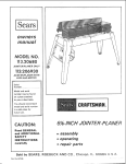
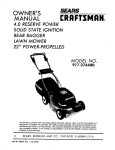
OWNER'S
ANUAL
CRI:IFTSMRN,
MODEL NO.
" 917.372330
0 RESERVE POWER
POWER-PROPELLED
LA WN MOWER
THIS MOWE.q
-. m. ,,:-. ? . _,,
TO DEPREf-L: --FOR FUf;-:EF
5"
SEARS,
"_,' " "
." " •
No
87000
Re,,," 0
. -,J. "- ._A"
."
ROEBUCK
Ib
Part
"-
:2. 2..-; £6
_ "..5
O"-: EFCECTI",,"E
- :. '4D:',._.';. _EHIND
' "_
AND
"r_l,S
CO.,
J'JNE
THE
30
t9S2
MOVVER
TO sm;..,€{"r _H-..£ E',_GtNE
BEI:ORE
_L'-'.-
NL": 0'_
:'HE
:T IS NECESSAR'r
STARTER
MANL.,AL
CHICAGO.,
IL 6O684
U.SA.
ROPE
CRAFTSMAN
TWO
quality LAWN CARE equipment.
YEAR
LIMITED
WARRANTY
ON CRAFTSMAN
POWER
MOWER
For two years from the date of purchase, when this Craftsman power mower is maintained, lubricated and
tuned-up according to the instructionsin the,owner's manual, Sears will repair, free of charge, any defect
in material and workmanship.
If this Craftsman power mower is used for commercial or rental pruposes, this warranty
90 days from the date of purchase.
This warranty
applies for only
does not cover:
-
Expendable items which become worn during normal use, such as rotary mower blades, blade
adapters, belts, air cleaners and spark plug.
-
Repairs necessary because of operator abuse or negligence, including bent crank-shafts and the failure
to maintain the equipment according to the instructionscontained in the owner's manual.
WARRANTY SERVICE IS AVAILABLE BY RETURNING THE CRAFTSMAN
NEAREST SERVICE CENTER/DEPARTMENT IN THE UNITED STATES.
POWER MOWER TO THE
This warranty gives you specific legal rights, and you may also have other rights which vary from state to state.
SEARS, ROEBUCK and CO. Department 698/731A
MAINTENANCE
A SEARS MAINTENANCE
AGREEMENT
NEAREST SEARS STORE FOR DETAILS.
AGREEMENT
IS AVAILABLE
CUSTOMERS
Sears Tower, Chicago, III. 60684
ON THIS PRODUCT.
CONTACT
YOUF
RESPOSIBILITIES
Read and observe the rules for safe use. Always use care When using your fawn mower. Keep away frorr
moving parts.
DO NOT work on your Jawn mower with engine running. Atways keep .your mower cleon.
Follow a r.:.aular schedule in maintaining, caring for and using your lawn mower. A well cared for mowel
will run an_ last longer.
Follow the instructions under "Maintenance"
and "Storage"
sectionsof *his Owner's Manual.
Blade, blade flange, air cleaner!a;r filter, spark plug are expendable
TABLE
parts which are your responsibility
OF CONTENTS
WARRANTY ..................................................
KNOW YOUR CR,a.FTSMAN MOWER .............
- ..........................
RULES FOR SAFE USE ..............................................
HELP YOUR LAWN MOWER LAST LONGER ..................................
HOW TO SET-UP YOUR MOWER ......................................
BEFORE STARTING ENGINE
................
HOW TO USE YOUR MOWER ............
MAINTENANCE
..........
STORAGE ....................
REPAIR P_TS
ENGINE REPAIR PARTS
TROUBt E SHOOTING
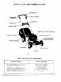
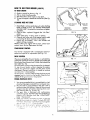
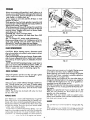
KNOW
YL,)UR
RAP1-SMAN MOWER
-
CONTROL
ZONEIENGINE_
DRtVECONTROL
BAR
CONTROL
PLATE
CABLE CLIP /
HANDLE
KNOB
/
GRASS
ENGINE OIL CAP WITH
DIPSTICK
•_OLINE FILLER CAP
WHEEL ADJUSTER
ON EACH WHEEL)
HANDLE BRACKET
AIR FILTER
DRIVE COVER
HOUSING
FIG.
i
MEETS CPSC BLADE SAFETY
REQUIREMENTS
SPECIFICATIONS
TOOLS
Oil: Use SAE 10W30 motor oil. SAE 30
motor oil can also be used.
FOR CATCHER
3!8 and 71t6
Power
Rotary
WaEk-Behmd
Equipmen,
Institute
Pov_e_
and
,%_.ower:
U S
-_::,c",_
Cons_rr'e
_ P'-_.:.
'-
'-,-,
"
ASSEMBLY
' wrench or
adj}Js,able ,,vrench
Medium t!ot blade screwdriver
FOR BLADE REMOVAL
S'c;,c:a__ :5,'_'"
box e_ open
e ,d .re-,oh
Gasoline:
Use unleaded
automotive
gasoline. Regular automotive gasa!ine can
also be used. DO NOT use oreT:um
=
L
gasoline, or gasoline containing _,ce,_o_
Sears
REQUIRED
--:.T:,.,
_,,",",
":'"':.
_-
-2," .... <s:,:,c
....
e _".,"
o..':.::-o,:_:z.e
:L: _ %.:':,.",.a
L_rc_a,'_ras
I,_sf,tu{e.
Outdoor
RULES FOR SAFE USE
CAUTION: ALWAYS DISCONN_:CT SPARK PLUG WIRE AND PLACE WIRE WHERE IT
CANNOT CONTACT SPARK PLUG TO PREVENT ACCIDENTAL STARTING WHEN
SETTING-UP, TRANSPORTING, ADJUSTING OR MAKING REPAIRS TO YOUR MOWER.
IMPORTANT
FEDERAL REGULATIONS REQUIRE THE ENGINE CONTROL INSTALLED ON THIS MOWER IN ORDERI
THE RISK OF BLADE CONTACT INJURY. DO NOT UNDER ANY CIRCUMSTANCE ATTEMPT TO DEFEA
TION
OF THE OPERATOR CONTROL.
I.
15.
Please read your owner's manual.
Only a!_ow persons who know the
safety rules to use your mower.
DO NOT tie the control bar to the
2.
DO NOT
mower.
allow children
Remove all sticks, stones, wires, cans,
boards, etc. from area to be mowed.
These objects can be thrown by the
blade.
damage
r_
t6.
Always stop engine when no
grass or when crossing graw
sidewalk, or roadway.
17.
Never
always
18.
Never use your mower with
per guards or deflectors in
19.
Always mow across a slope
ed area. DO NOT mow up
a slope or inclined area.
20.
DO NOT mow in wet grass, r:!
run with the mower.
_!
21.
DO NOT run your mower}
Exhaust gases are deadly
22.
DRAIN
23.
DO NOT run your mower if if
too much. Stop engine a_
repairs. Vibration is an indi
damage.
24.
DO NOT change the engin
nor settings
to over-sp
engine--damage
or injury c
25.
If a grass catcher is used
mower, check the catcher
damage or deterioration.
normal use it will wear.
recommended
replacemen
Always
stop engine
to
catcher.
26.
DO
to use your
Check your mower over before each
time you mow. Tighten any loose
bolts, nuts, etc.
,
use a damaged
Always
have
before mowing.
handle. Control must be free to permit brake engagement when handles
and control are released.
3.
DO NOT
pull mower towarc
follow mower to cut
i
6.
DO NOT allow children, bystanders,
or pets in the mowing area.
7.
BE CAt_EFUL-WHEN
THE ENGINE
tS RUNNING
THE BLADE
IS
TURNING.
8.
Always shut off engine before trying
to adiust wheel heights.
.
When engine is running, DO NOT put
hands or feet under mower or in the
discharge
chute, nor make any
adjustments.
Stay clear of discharge opening at all
times.
Check gasoline
before
each use. Do
not fill _as tank when engine is running, wnen indoors or when engine is
hot. Allow engine to cool for several
minutes before filling gas tank. Clean
off any spilled gasoline before starting engine.
12.
Mow
only in good
light.
i
Disengage
propeJied
engine.
tad
J
transporting your mower ins_
car or other vehicle,
i
NOT
gasoline
13. Wea,- "_nJysoi;d shoes ,..,,henmowing.
DO NOT
operate
mower
when
barefoot, or wearing open sandals
THE GASOLINE
store
your
where,fumes
rr
may i
open Flame .--:ha cause a fi i
27
drive control on power
mowers befcre
starting
4
A:ways .v_ar safety glass_
shields oerore ;._artmg y_
mower and while mow,ng!
SAFETY
GLASSESThe operation of any lawn mower can result in foreign objects thrown into the
eyes, which can result-in severe eye damage. Always wear safety glasses or eye
shields before starting your lawn mower and while mowing. We recommend Wide
Vision Safety Mask for over the spectacles or standard safety glasses, available
at Sears Retail or Catalog Stores.
ACCESSORIES
TO HELPYOU GETTHEMOSTFROMYOUR MOWER
CI'IPPING DEFLECTOR: Converts rear bagging mowers to side discharge to disperse clippings safely and eventy.
HIGH WHEEL KIT: A pair o_ 12-inch rear wheels improves handling on soft, spongy lawns and uneven terrain. NOTE:
If the 71 33721 High Wheel Kit is purchased as an accessory, the cutting height range will be reduced to five (5) different
positions; from 1 I/2" to 3 1/2".
MOWER COVER: Sears Tyvek_cover protects mower from weather when stored outdoors.
GAS CAN: A new gas can keeps rust and dirt out of fue! systemfor longer engine life and improved performance. Craftsman gas cans have built in filters to keep impurities ou_ of your engine.
THESE ACCESSORIES WERE AVAILABLE AT MOST SEARS STORES AND THROUGH THE CATALOG ATTHE TIME
THIS MANUAL WAS PRINTED.
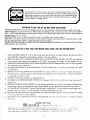
IMPORTANTTIPSTO HELPYOUR LAWN MOWERSTARTFASTER,RUN AND PERFORMBETTER
1.
USE UNLEADED GASOLINE:
It burns cleaner and leaves less residue in the engine. Regular gasoline can also be
2.
used. DO NOT usegasoline containing any alcohol or with any additives.
DRA1N OR RUN-OUT ALL GASOLINE FROM TANK AT THE END OF THE SEASON:
in your mower when stored for tong periods. It will "GUM"
DO NOT leave gasoline
your engine. Run engine until the gasoline runs out.
3.
START EACH MOWING SEASON WITH FRESH GASOLIN E: DO NOT keep gasotine in your can. If your gasoline
can is starting to rust, replace can.
4.
CHANGE
YOUR SPARK PLUG EVERY SPRING: An old corroded
spark ptug prevents fast starting and smooth
running engine.
5.
6.
REPLACE YOUR AIR CLEANER OR F_LTEROFTEN: Dirt, along with heat can harm your engine, the cleaner or
filter will clog up, preventing clean air from reaching your engine. See "Air Cleaner/Filter ' section of this manual
for replacing air cleaner or filter.
USE SAE 10W30 OIL: DO NOT use SAE IOW40 oil.
7.
CHANG_E OIL AS RECOMMENDED:
hours of use.
IMPORTANT - change oil after the first two (2) hours of use, then every 25
8.
REPLACE THE BLADE WHEN NEEDED: You can sharpen the blade, but we do not recommend it. Erosion from
hitting foreign obiects can damage the blade. Replace blade with one specifically designed for your mower.
9.
AT THE END OF THE SEASON, CLEAN YOUR MOWER:
IMPORTANT - first disconnect the spark plug wire. If
possible, store your mower in a well ventilated area and protected from moisture.
10. FOLLOW THE MAINTENANCE SUGGESTIONS IN YOUR OWNERS MANUAl:
Read your manual and keep
it in a convenient place for easy reference.
11. DO NOT PUT ANY ADDITIVES IN THE OIL OR GASOLINE:
any alcohc:.
NOISE
88
Noise
levei
DO NOT US£ GASr_HOL,
or gasoline containing
RATING
DECIBELS i A ' 'EIGHT :
._::n ,ar z d_,e to ,'nan _foc_._r'_,g
,,ariance,
eng,ne
s_:'e, .._.qd olc_de
._ _=.
-
-,,.
:.
-,_;,::- _,_.cc.:'-
ditions ard 'ype of operation. Thi,_ -o]se rat._g "s based .jpon mea_ureme_ 'r:_e_ q_ "__ :'Oera "Or' : _ar
on a representative sample(s) and is subiect to verif!catJon by a,_ indecerden* :es_.r:c,acorctorv.
_
Your lawn mower has been completely assembled at the factory, except for the grass catcher and grass catcher fr
To set-up and attach grass catcher, follow the steps under "GRASS CATCHER".
The following parts are included not assembled;
I
Grass Catcher Frame
1
Grass Catcher Top
1
Grass Catcher Bottom
1
Hardware Package
1
Catcher Handle
HOWTOSET-UP
YOURMOWER
I
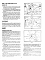
TO UNFOLDHANDLE
I. Raise the handles until the lower handle is in mowing
position (See Fig. 2).
NOTE: The lower handle automatically locks into mowing position when raised from shipping to mowing
position.
2. Raise the upper handle intoposition on the lower handle and tighten the two (2) handle knobs.
3. The handle can be moun*ed in high or low position
to suit the comfort of the user. The handles are shipped mounted in the high position.
4. If the handle feels too high for you:
a. Remove the two [2) screws, one (I] bolt and
and Iocknut holding the trim plate and rope guide
to lower handle. Keep for re-assembly (See Fig.
FIG. 2
tOW£_
HAN
|T
SPRING
I).
b. Remove the handle knobs and bolts from upper
and lower handle.
c Remove the hairpin cotters (See Fig. 3).
d. Turnhandle aver, position handle levers in place
{See Fig. 4).
e. Put handle back on mounting pins (See Fig. 3).
f. Put springs and hairpin cotters back in mounting
pins (See Fig. 3).
g. Put upper handle on lower handle using handle
bolts and knobs previously removed.
h . Puttrim plate and rope guide back on lower handle, removed in (a) above. Tighten the two (2)
screws and ane (1) bolt {See Fig. I).
i. Snap cable clip over cable and lower handle (See
Fig. 1).
5. To fold handle for storage., squeeze the handle levers
until lower handle clears handle brackets, then move
handle forward (See Fig. 3).
i
,,,
i
i
ii
i
ii
iiiiii
MOUNTING
COTTER
FtG. 3
i
JCAUTION:
WHEN
FOLDING
HANDLE
FOR i
I TRANSPORTING OR STORAGE, BE SURE TO FOLD I
IHANDLE AS SHOWN IN FIG. 5. IF YOU FOLD HAN- |
IDLE THE WRONG WAY, YOU MAY BEND THE CON.|
ITROL
CAB,
LES.
PiN
HAIRPIN
.....
FIG. 4
2r High cut is approximately
4-- medium cut is appr
imately 2 t/2"' and low cut is approximately
! 3,
"There are four (4) other positions. Pick the posi_
which suits you for best cutting (See Fig, 6).
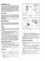
3. The wheel adjusters on your lawn mower can be ea
adjusted as shown in Fig. 7. To change the heigh
cut, squeeze adjuster lever toward the wheel, m
ing up or down to selected height. Be sure al! wh_
are in the same setting (See Fig. 6).
4. When cutting in heavy o_ moist grass, the rear of
lawn mower may be raised one setting higher *o all
better a;schcrge of :he Grass.
NOTE' tf the -" 3372 ! High Wheel Kit is purchasea
an accessory, the cutting height range witl be reducec
five (5) different positions,, from ! 1/2" to 3 1/2"
I
TO ADJUSTHEIGHTOF CUT
NOTE: The wheels are set in a low cut position for shipment. and shouJd be adjusted far the cutting height desired
before use NOTICE: Lowering wheels raises the height
of cur.
CAUTION:
DO NOT change the height of cut with ;ne
eng._e runm'na
t Th= _ee/ad;_'5:ers g,ve vau seven [7) differen" cut",rig po_.t_ons _edium cu!! ;s the best ;or most lawns
6
HOW TO SET-UPYOURMOWER(CONT'p)
REARDEFLECTOR
The rear deflector, attached between the rear wheels of
,our lawn mower, was assembled at the factory and requires no assembly.
TO ASSEMBLE
GRASSCATCHER
NOTE: The grass catcher for your mower is supplied
unassembled. To assemble your grass catcher follow steps
below.
SCREWS
ACTUAL
SIZE
LOW
1/4-20 x 3/4"
SCREW
I li!
!
_._
#/0.24 x 5/8
SCREW
I. Position clamp onto catcher frame as shown in (Fig.
8) and close ends of clamp.
NOTE: When closing clamp be sure the holes in"clamp
are in line.
2. Put grass catcher frame with clamp installed into catcher top as shown in Fig, 8).
3. Put one (!) # 10-24 x 5/8 truss head screw into hole
in catcher top and clamp and install # 10-24 Iocknut.
DO NOT TIGHTEN (See Fig. 7).
4. Put three (3) # 10-24 x 5/8 truss head screws into the
catcher frame and install #10-24 tocknuts.
5. Locate and position the catcher handle on top of catcher top as shown in fig 8.
6. Install two (2) #10-24 x 5,8"" truss head screws thru
handle and catcher top. See Fig. 8.
7. Install two # 10-24 Iocknuts on the screws. See Fig. 8.
Use a flat blade screwdriver to drive screws while
holding the Iocknuts with adjustable or 3/8" wrench
(See Fig. 8).
8. Position baffle inside of catcher top as shown in (Fig.
9). Put#wo (2) # 10-24 truss head screws into holes
with two (2) #10-24 Iocknuts. Use a flat blade
screwdriver to drive screws while holding the Iocknuts
with adjustable or 3/8" wrench.
9. Position top haft of catcher on the bottom half (See
Fig. !0).
I0. Align the holes in sides of top and bottom halves of
catcher.
1 !. Install the eight (8) 1/4-20 x 3/4" truss head screws,
starting at the right front of catcher as shown in Fig.
10.
12. Instal the right front truss head screw thru the catcher and install one (1) stiffener on the screw.
13. Install the _,/4'" locknut on the screw.
14. Instafl the other seven (7) screws and nuts, on the last
or seventh screw install the stiffener and ]ocknut.
5. Use a medium flat blade screwdtiver to tighten the
screws while holding the "'Keps'" nut with adjustable
or 7/I6"" wrench.
NOTE: Check a!J screws and nuts to be sure they are tight.
WHEEL
_'C
ADJUSTER
SHOWN
LEVER
W_TH WHEEL
REMOVED
FIG. 6
FIG. 7
TRUSS
#10-24
HEAD SCREWS--___.__
x 518"_,_
"'_
_._
CATCHER
{'__!_/_/_//
--_15_ -,. ',
CATCHER
TOP
FRAME
"
_
e
._ -" ._.
,v
JG
CLAMP
HOW TO SET-UPYOURMOWER(CONT'D)
SLOTTED
HEAD SCREWS
CATCHER
BAFFLE
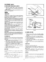
TO ATTACHGRASSCATCHER
1. Place the catcher frame into the slots of the hinge
bracket.
2. Depress the door latch tab and slide the frame into
position at the end of the slot (See Fig. 11).
3. Release door latch tab to lock frame into place.
4. To remove grass catcher, stop blade, lift up on back
of grass catcher with one (I) hand and press down
on the door latch tab with theotherhand (See Fig. 11).
5. When grass catcher frame is unlatched, remove catcher from the rear of the mower and empty.
6. When grass catcher is removed from the mower, the
rear door closes for safety.
CUTAWAY
OF CATCHER
TOP
LOCKNUTS
FIG. 9
NOTE: YOUR REAR BAGGER MOWER IS NOT A
MULCHING MOWER. DO NOT OPERATE YOUR
MOWER WITHOUT AN APPROVED GRASS CATCHER OR OPTIONAL CLIPPING DEFLECTOR IN
PLACE.
KEPS NUTS
1/4-20
x 3/4"
NEVER ATTEMPT TO OPERATE THE MOWER WITH
THE DOOR REMOVED OR PROPPED OPEN.
TO EMPTYGRASSCATCHER
•
PsNuTs
ST_IFFENERS
1. Lift grass catcher, by grasping the handle on top of
grass catcher and on therear of catcher (See Fig. 12).
2. To empty the grass clippings, shake the catcher, with
the open end overt or into suitable container for
disposal (See Fig. 12).
ii
FIG. 10
BEFORE
STARTINGENGINE
I. Remove engine oi! cap wit.h dipstick and fill to the
"FULL ""lin_ on the dipstick, using about I pint or 0.5
liters of Sears IOW30 oil or equivalent. 5AE 30 oil
can also bE. u._ed (See Fig. 13). DO NOT use SAE
lOW,_O oil.
The total oil capacity of your engine is 21 oz. or 0.62
liters. Fill only to the "FULL'" line on the dipstick. DO NOT
over fill. The first fill on a new engine use about
I pint
or 0.5 liters. Check oil level and add as required to bring
to proper level.
2. Pour oil slowly, DO NOT over fill.
NOTE:
On
a new
engine
some
oil
ma X be
left
FIG.
in the
engine, as each engine is run for operational checks
before shipping.
3. AFTER THE FIRST TWO (2) HOUR50FMOWING
CHANGE THE OIL. See "To Change Oil" section
under
maintenance.
Use only oil ",_'ithautomotive classifications SF, SE, 5D
or SC markings on ai; container.
4. Fill the goso/;ne
"ank ",_;t/:. about one and one haft (I
I.2) qda, "t: :z ;_esh c:ean unleaded
automotive
gasoline .Rec. _" "e_eu gaso.ne co,_ .;;so _e used
(See F'g "3")
DO ,_.'01-_,seo_a or stale aosohne which has been kept
from
oric
_c.a_.on "c ,:;_o,_,.'.,r
_'_:,ng
problems
can result.
s
11
BEFORE
STARTINGENGINE
GASOUNEFILLER
CAP
I
ICAUTION. DO NOT USE GASOLINE CONTAINING
IANY AMOUNT OF ALCOHOL, AS IT CAN CAUSE.
SERIOUS DAMAGE
OR CAN .SIGNIFICANTLY
,?EDUCE ENGINE PERFORMANCE:
I DO NOT USE PREMIUM GASOLINE .....
IDO NOT PUT ANY ADDITIVES IN THE OIL OR
IGASOLINE.
I Be sure your
gasotine
can is clean and Free of rust and dirt.
Rep,,laceyour can ff it has
storied
to rust..
iiii i
WUL_
"
"
ENGINE OIL CAP W/DIPSTICK
,HOW TO USEYOURMOWER
IMPORTANT
FIG. 13
ENGINECONTROL
i
CAUTION: THE BLADE TURNS WHEN THE ENGINE
IS RUNNING.
YOUR MOWER IS EQUIPPED WITH AN OPERATOR
ZONE ENGINE CONTROL WHICH REQUIRES THE
OPERATOR
TO BE POSITIONED
BEHIND
THE
MOWER HANDLE TO START AND OPERATE THE
MOWER.
THE CONTROL BAR MUST BE DEPRESSED TO THE
HANDLE TO START AND RUN THE ENGINE, RELEASING THE CONTROL BAR WILL STOp .THE ENGINE.
AN INTERNAL ENGINE BRAKEASSIST5 THE BLADE
tN STOPPING QUICKLY.
WHEN THE OPERATOR LEAVES THE NORMAL
MOWING POSITION TO REMOVE THE GRASS CAT"HER, CHANGE THE CUTTING HEIGHT, PICK UP
,JTICKS OR OTHER OBJECTS IN THE MOWING PATH,
THE. ENGINE WILL AUTOMATICALLY
STOP WHEN
THE CONTROL BAR 15 RELEASED.
ENGINE
CONTROL
LEVER
.........
CAUTION: FEDERAL REGULATIONS REQUIRE THE
.ENGINE CONTROL INSTALLED ON THIS MOWER IN
ORDER TO MINIMIZE THE RISK OF BLADE CONTACT
INJUR Y. DO NOT UNDER A N Y CIRCUM5 TANCE A TTEMPT TO DEFEAT THE FUNCTION
OF THE
OPERA TOR CONTROL.
. CO:JIROL
"t!,_. ,'----- ZONE, ENGIN£
")_
ENGINECONTROL
TO ENGAGE
DRIVE
The engine speed is controfled by a lever (red knob)
located on right side of engine. It has "HIGH"
and
"LOW"positions.
"'HIGH" position is for starting engine,
heavy cutting and better grass bagging. "'LOW" podtion is for light cutting, trimming and fuel economy (See
3.
TO STARTENGINE
HAN_DLE
4.
BAR MUST
TO START
BE DEPRESSED
.¢_ID RUN
THE ENGINE.
re .___.'._is_
_._:_r*'n,",=,
Check oil :eve . c_ec;, gasol;ne
_ank for goso/ine;
make sure spar_ o/ua wire ;s attached.
15
When,starting
a cofd engine, push the primer five (5)
times before pulling
starter rope. Use firm pushes
when pushing primer, watt several seconds between
each push _See Fig. 14).
Repeat step 3 above as req,fired.
' NOTE: In cooler weather the ,'_eed fo repea t priming procedures ,'nay be neces.:ary ;,.her .veather i_ warm.er over
priming may result _ HOO__.'"
- HZ_
If you do fJooc ena:ne ,.'.-.'t a r_, n;mutes before
repeating printing Foc_ J .'res.
TO THE
,
t,
NOTE: The c_rburetor haa fixed
fuel mixture and has
a primer
CONTROL
DRIVE CONTROL
DISENGAGED
C O",iT RC'L
FIG.
:
Fig,l,#.
THE CONTROL
-4
':"\.€.,
tt
and
2. Push lever f_r*,ard to "HIGH'" nosition (See Fig. 1.4).
g
-s not
nece;:,::rv
:2
. ,_ ": ......
.-.-
_ _ m
engine.
HOW TO USEYOURMOWER(€ONT'D)
CONTROL
TO STARTENGINE
5.
6.
7.
8.
Position yourself as shown in Fig. 17.
Pull on starter handle quickly.
DO NOT allow starter rope to snap back.
To stop the engine, release the control bar {See Fig.
16).
IF ENGINEDOESNOT START
INE
"1. Check blade - remove spark plug wire When checking
blade. If blade is loose, see "BLADE AND BLADE
FLANGE CARE" of manual for instructions on tightening blade.
2. Check air filter - replace if clogged. See "Air Filter'"
section..
3. Check spark plug - if dirty, clean or replace.
4. Observe that lower end of the engine control cable
is actuating the lever mounted on the engine.
5. Engine may be flooded - wait a few minulgs and
repeat starting procedure.
NOTE: If then your engine will not start, contact your
nearest Sears Service Department for help.
DEPRES._
RELEASED
ENGINE
START.
STOP
FIG.
I
16
ZONE/ENGINECONTROL
Your mower is equipped with a zone/engine control
tached and requires no adjustments (See Fig. 15).
at-
DRIVECONTROL
FIG. 1 7
The power-propelling
forward motion is controlled
by
pulling the control bar down to handle and pushing the
drive control lever forward until it clicks, then release the
lever (See Fig. 75).
Forward motion will stop when the control bar is released.
To stop forward motion without stopping
the engine,
release the control bar slightly until the drive control
disengages.
Depress control bar to handle to continue
mowing witho,..I self-propelling.
To turn corners, you may prefer to keep the drive control
engaged, and p.,sh dawn on the handle, lifting the front
wheels off the ground and tu-ning mower.
\_.
SCREWS
I
! ,'l.l (-----..-------_"
/
d ,
_.._,1
\
'
I
POWER-PROPELLED
DRIVE
I.
Your power-propelled
drive is accomplished by a belt
drive from the engine crankshaft to a worm gear case.
2. The drive belt is spring-loaded
at the gear case to
maintain proper belt tension. Keep the area around
the gear case clear of trash by removing drive cover
and cleaning (See Fig. 18 and 19).
3. The gear case is lubricated
with multi-purpose
automotive grease. DO NOT USE ANY OTHER type
9rease or oil in the gear case. See "GEAR CASE"
under "Maintenance".
4 Check your mower, each time you mow, to be sure
that the front wheels tur_ freely. !f wheels DO NOT
÷:,,n _ree/v remove any "rash which may have gotten
into the _noe. F...:.c ? ,:r b-or'ng
areas
5. If a: :,_ ',me..'he _r.'_e heir ;s rep_acea, J_e only rac°.-ry
sped : e:.- .:_:."
"4- _a:
only"
;:e c'_d mox_mbm
FIG
""'_'_
"
"_
18
"_--_-_._ '
I
I
I
-i
IC
HOW TO USEYOUR MOWER(CONT'D)
BLOCK
OF WOOD
MOWING TIPS
1. Under certain conditionsit may be necessar'yto raise
the height of cut to keep from overloading the engine
and leaving clumps of grass clippings.
2. For extremely heavy cutting, make the width of your
cut 1/2 to 3/4 the normal cut. Thiswill reduce the load
on the engine and give you cleaner cutting and
o bagging.
3 The user should note that when cutting moist, heavy
grass with a rear bagging mower, clumps of cut grass
may fail to enter the grass catcher. To pick up the
clumps if they occur, run the mower over the area a
second time.
4. Under certain conditions a trail of grass clippingsmay.
be left at the right side of the mower. Mowing in a
clockwise direction with a small overlap will allow
these clippings to be collected on next pass.
FIG. 20
MAINTENANCE
Be good to your mower. Once a year put on a new
mower blade, a new spark plug, and a new air filter. A
new blade cuts better. With a new sparkplug your engine
will start and run better. A new air filter assure proper
air-fuel mixture. It will help your engine run better and
last longer.
MOWER:
FIG. 21
BLADE/BLADE
FLANGECARE
\\
CAUTION: Protect your hands when removing or installing blade of your mower• Wear heavy gloves
and/or wrap blade with heavy cloth when holding
blade. Always use a block of wood when tightening
blade nut or blade bolt•
_,,,,,
_r :
/
\
.Use only a Sears authorized
replacement blade to get
the best c'utting results.
CAUTION:
Disconnect spark plug wire from spark plug
and place wire where it cannot come in contact with the
spark plu_).
I.
To remove the blade and blade flange, turn mower
on its side with carburetor and air filter up (See Fig.
FiG. 22
20).
2.
Take blade nut off by turning counter-clockwise.
Use
a 15/16"
box or open end wrench on the blade nut
(See Fig. 20),
3. Put a block af wood between the blade and mower
housing to. prevent blade rotation when removing and
tightening
blade nut.
NOTE: Always check the blade flange when changing
the blade to be sure tab has not been damaged (See Fig.
21).
4. If the tab in the blade flange is damaged replace ti:e
blade flange
5.
Put the blade flange on the engine crankshaft with the
tab in the slot of the crankshaft (See Figr 2 t).
6. Put the blade on the crankshaft as shown in (Fig. 2 t).
Be sure the word "TOP"
(stamped in the blade) is
toward the engine.
;7. Install the flat washer, tw¢ !'2) formed washers and
blade nut os removed ob._ve
NOTE: We recommena :ha, "._e blade nut be replaced
r
when restarting a _ew a,ade.
8. Tighten hi,de n,Jt. The red3mme._.deS, tightening torque is 50-65 ._. ibs. Use _".cc;: o( wood to prevent
blade rotation.
NOTE: Tora_,e "_:encn_s c:'_. c_ _ ::Die _ .'no:: Sears
NOTE
.The b.'ade flange _,ith tab attaches _he blade to
crankshaft, it _snot intended to protect the crankshaft. The
tab must be in good condition and located in slat of
crankshaft
to keep blode attached
_:_r:b''_
retail srore_ on ! ,_r,_u_h ":he cor;,",.'_2
A loose blade ca- "es_'.', r
s'a,-ting
!1
o: engine.
MAINTENANCE(CONT'D)
BLADE/BLADE
FLANGECARE(CONT'D)
HEX HEAD
SCREW
We DO NOT recommend sharpening blade - y_u can
keep the cutting edge touched up with a file. Grinding the
Cuttingedge excessively can cause the blade to be out
of balance. An unbalanced blade can cause excessive
vibration and shorten the life of the engine and mower. _
REARDEFLECTOR
The rear deflector which is attached to the rear of your
mower is to keep objects from being throv2n out the back
of the mower. If your rear deflector becomes damaged
you should replace it (See Fig."24).
FIG. 23
TO ADJUSTDRIVE CONTROLCABLE
NOTE: THE DRIVE CONTROL CABLE SHOULD BE
CHECKED OFTEN TO BE "SURE THAT GEAR CASE
SHIFTER IS FULL Y ENGAGED OR WHENEVER SERVICE HAS BEEN PERFORMED ON THE GEAR CASE
OR DRIVE CONTROL COMPONENTS,
1. To adjust, remove the drive cover by removing two
(2) screws. Keep for re-use (See Fig. 18).
2 ;'Loosen cable clamp screws "'A '" &. "B'" (See Fig.
2_).
3. Loosen both jam nuts "C ""& "'D" at the cable clamp
an the gear case adjusting bracket (See Fig. t9).
4. Unhook clutch spring from shifterarm (See Fig. 19).
5. Hold, dip or tape down the drive control bar and
engage the drive control fSee Fig. 15).
6. Move the shifter arm to drive position. To be sure
the jaw clutch is fully engaged, rotate the front
wheels.
7. Hold shifter arm in fully engaged position by pliers
as shown in Fig. 19. DO NOT pu/l on control cable.
8 Tighten/am nut "C'" up to bracket until cable is snug.
9. Tfghten cabJe ciamp screw "'B" ISee Figs. 19).
I0. Tighten jam nut "D" up to bracket (See Fig. 19).
11. Tighten screw A'" (Fig. 25).
12. Putclutch spring back in place an shifter arm, removed in step 4 above.
13. With drive control in eng ga
edposition,. ....push
mower
•back and forth to be sure gear case is fully engaged.
NOTE: Be sure to disengage drive control before Starting engine.
14. Put drive cover back in place, removed in step 1
above.
REAR DEFLECTOR
FIG. 24
\
/
FIG: 2 5
NOTE: Thegear case is filled to proper level at the factory. The only time the lubricant needs attention is ff service has been performed on the gear case.
l'he gear case must be filled with grease after gear case
has been serviced. Use only multi-purpose automotive
grease. Do not substiiute.
GEARCASE
I.
2.
LUBRICATION
THE GEAR CASE AND AREA AROUND
ALL THE
DRIVE SHOULD
BE KEPT CLEAN AND FREE OF
[RASH BL.'t'.D.UP
To check gear case area.
a Remove the drive cover by removing thetwo/2)
_crews (See Fig. !8). Keep for re-use.
b. L,,;an trash from around gear case.
Put drive :over ba:k. re.n_ved -n {a) above.
MOWER WHEELS: Lubricat;ng wheels and/or wheel
bearings is not necessary under normal conditions.
Should condition5 reauire. /ubricaiton, thoroughly clean
wheels and/or ,vhee, bearings and axles and apply a li_
coating of dr;; !ubr;cant
REAR DOOR HINGE: Put a few drops of the same oil
as used in the engine on hinge points Of rear door once
12
MAINTENANCE (CONT'D)
GEAR CASE: The gear case is filled at the factory and
does not require any addition of lubricant, unless the gear
•ase is opened andservice performed. Use only a multi_urpose automotive grease for refilling after service has
"been performed.
Approximately
2 1/2 oz. required.
FRONT WHEEL ADJUSTERS:
Put a few drops of the
same oil as used in the engine on the front wheel adjusters
once or twice each year (See Fig. 27).
GRASSCATCHER
Check your grass catcher often for damage or deterioration. Through normal use # will wear. If catcher needs
replacing, replace only with a manufacturer approved
replacement catcher from Sears. Give the mower number
when ordering.
NOTE: The catcher may be hosed "with water, but must
be dry when used.
FIG. 26
COTTER
HAIRPIN
I "
WASHER
ZONE/CONTROLLEVER
Put one or two drops of the same oil as used in the engine
between the zone control lever and bracket located on
left rear of engine (See Fig. 28).
each year.
"_
Do this once or twice
OIL HERE
E_CH
SIDE
CLEANING
CA UTION: Disconnect spark plug wire from spark plug
and place wire where it cannot come in contact with the
"oark plug.
Turn mower on its side with carburetor up.
21 Clean the underside of your mower by scraping to
remove build-up of grass and trash.
NOTE: We recommend that you clean the underside of
your mower after each use.
3. Clean your mower and engine often to keep build-up
of trash from accumulating around engine, a clogged engine runs hotter and shortens engine life.
NOTE: We DO NOT recommend using a garden hose
to clean mower unless the electrical system, muffler, air
filter and carburetor are covered to keep water out.
Water in engine can result in shortening engine life.
b. Remove wheel from wheel adjusters.
c. Remove any trash, grass cuttings from inside the
dust cover, pinion and/or drive wheel gear teeth.
d. Put wheels back in reverse of removal.
3. If after cleaning drive wheel area, the drive wheels
DO NOT rotate freely, the gear case needs care.
NOTE: If your gear case requires service _'e suggest that
you contact Sears Service Center.
TO CHECKAND/TO REPLACE
BELT
GEARCASEAND DRIVEWHEELS
I.
Remove the drive cover by removing
the two (2)
screws (See Fig. t 8).
2. Inspect belt far wear or damage. If you decide to
replace:
a. Push down on gear case pulley until belt can be
removed from gear case pufiey (See Fig. 22).
3. Turn mower on its side with carburetor
up.
4. Loosen hex head screw ho/din 3 beit snubber in place
and move belt snubber away from pulley (See Fig.
23).
5. Remove belt from engine pulley on crankshaft
and
carefuJiy slip ;he _e,: at:." ._ _r ,_,e b;ade.
CAUTION:
The shako edge.', of _,!ade can cut the belt.
Use care in installing new be;.t over _tade
6. To install new pelt. rever<e cr:,:edc, r.,, r_s above in
NOTE: The gear case and drive wheels should be cared
for much like you would on automobile.
I. On a regular schedule remove the drive cover and
remove any trash around gear case and belt area.
2. To remove arive cover, remove the two (2) screws (See
Fig. 18). Keep for re-use.
3. Keep your mower clean and properly
lubricated.
DRIVE WHEELS
NOTE.
mow,
t.
C6e:_
to be
_on:
_.jre
The wheels
_:"-,_
,.,,heels
:h_.v move
n,,;: ,jn.na
each
time
freely,
indicates
cuttin£,s
ere _'9 .n the drive
wheel
be cle_ne,f
"o .:' _
.Jr
_- e
v, heels.
2.
if necessary
check both
o.
"o c.:ean ;he dr;;'e
[root wheeis
Remove
hub .=aos
Keep
,,or re-u_.e
before
you
freely.
hairpin
trash,
area,
grass,
and
must
remora.'.
wheei_
(See
Ftg.
2, 7)
cotters
and
washers.
13
MAINffNANCE (CONT'D)
TO CHECKAND/TO REPLACE
BELT(CONT'D)
\
7. Move belt snubber back in place, approximately
1/32" away from belt and tighten-hex head screw
(See Fig. 23}.
NOTE: Always use only factory approved beJt to assure,__
proper fit and longer life.
ENGINE:
ZONE
CONTROL
LUBRICATION
LEVER
ENGINE:
use of proper oil in your engine and keeping
to full level is essential. Changing oil regularly
will
lengthen the life of your engine.
The total all'capacity
of your engine is 21 oz. or 0.62
liters. Fill only to the "FULL" line _onthe dipstick. DO NOT
over fill. The first fill on a new engine use about I pint :
or 0.5 liters. Check oil level and add as required to bring
to proper
level.
NOTE: On a new engine some oil may be left in the
engine, as each engine is run for operational
checks
before shipping.
Use Sears SAE lOW30 oil or equivalent. SAE 30 oil can
also be used. DO NOT use SAE lOW40 oil.
Use only oil with automotive classifications SF, SE, SO
or SC markings on oil container.
Using Sears 5AE !OW30 oil wilt assist engine starting
in cool weather.
\
]
FIG. 28
CONTA}NER
Running your engine with oil be/c w safe level or with dirty
contaminated oil can contribute to shortening the fife of
your engine.
After the first two (2) hours of mowing change the oil, then
change the oil every 25 hours of mowing thereafter.
If
you mow under dusty, dirty conditions you may need to
change the oil more often.
FIG. 29
TO CHANGEAIR FILTER
1. Remove the air filter cover by turning
counterclockwise to the stop, and pull away from collar (See
Fig. 30).
2. Remove filter from inside of cover (See Fig. 30).
3. Clean the inside of the cover and the collar to remove
TO CHANGEOIL
CAUTION: Disconnect spark plug wire from spark plug
and place wire where it cannot come in contact with the
spark plug.
1. Remove engine oil cap with dipstick, Jay aside on a
clean surface. Warm oil drains better. "
2. Tip mower on its side as shown n Fig. 29 and drain
oil into suitable container. Rock mower back and forth
to remove any oil trapped inside of engine.
3. Wipe off any spilled oil on mower and/or inside of
engine.
4. Fi!l engine with oil, filt only to the "FULL" line on the
dipstick. DO NOT over fill.
5. Reconnect spark plug wire to spark plug.
4.
5.
any dirt accumulation.
Insert new filter into cover.
Put air filter cover and filter into collar
tab with the slot.
6.
Push in on cover and turn clockwise to tighten (See Fig.
aligning
the
30).
SPARKPLUG
Change your spark plug each year.
A new clean spark plug will make your engine start and
run better. Keep your spark plug clean. Set spark plug
gap at .030.
Recommended
replacement
Sears
spark
plug
no.
74 333 t2 or STD36 t458 are available
at mast Sears
retail stores and through the catalog.
AIR FILTER
CAUTION:
DO NOT run your engine without air filter
in p/ace
I. Y=_'" engine wil! not run properly with a clogged, dirty
air filter.
NOTE. DO NOT wash this type air filter
2. ReD".ace your air ;,/_er each year, more o_en ;f you
mo_. - very dus_v aJ,rty conditions
Re_.'acemen: c,r freer no "" 3332 ,s availabie
at most
_"
oetait stores and through the catalog
GENERAL
DO NOT Jse gasoline left over from previous season. Otd
or stale 5,r'v g_s_lme c::'" ca_'se _tarting and running
problems
Replace !our gasoline ca.,. _f your old can starts to rust
DO NOTuse
rusty gasohne can. rust and/or dirt in your
14
STORAGE
Never store engine with gasofine in tank, indoors or in
closed, poorly ventilated areas where gasolinefumesmay
reach an open flame, spark or pilot light as on a furnace,
rater heater, or clothes dryer, etc.
ff your engine is not to be used for _3.0days or more
prepare as follows:
Drain gasoline from fuel tank; gasoline in gasoline tank
.and carburetor will form deposits and causeproblems in
starting and running your engine.
:
'
"
When preparing your mower for storage it isa good time
to serviceyour mower Ondengineto be ready for the next
mowing season. Replace such parts as mower blade,
spark plug and air filter;__...... •
CHANGE OIL: Worm oil drains better.
Drain old oil and replace with fresh Clean Sears SAE
lOW30 Oil.
. .
See "_ToChange Oil" section under Aflaintenance.
Remove spark plug and put 2 or 3 tablespoons of oil into
spark plug opening and putt starter rope slowly to
distribute oil, install new spark plug and tighten.
DO NOT PUT AN YADDITIVES IN GASOLINE OR OIL.
TO TIGHTEN
FIG. 30
CLEANMOWER/ENGINE
CAUTION: Before cleaning mower, disconnect,spark
plug wire and place wire where it cannot come in contact
with the spark plug ....
Clean around engine and on top of mower. Scrape underside of mower using putty knife or similar tool to remove
any build.up of trash Or grass on underside of mower
_ousing.
,_iOTE: We DO NOT recommend using a Water hose to
clean your mower unlessthe electrical system,muffler, air
filter and carburetor are covered to keep water out.
Water in engine can result in shortening engine life.
• FIG. 31
GENERAL
Always stareyour
mower on its wheels_ Stodng mower
on its side .or end may result in difficult starting. _.
When removing your mower from storage, fill gasoline
Check all fasteners and be sure they are tight: tighten
tank with fresh, clean, I unleaded, automotive gasoline.
and/or replace any loose or worn fasteners.
Check and fill oi! to proper level.
....When
starting your engine the first time after being in
GRASSCATCHER
storage for extended period, the engine may smoke for
a whileuhfil the englne, burns any oil or gasoline acCheck your grass catcher often for damage or deteriora•cumulated during the storage period.
tion. Through normal use it will wear. If catcher needs
...........
DO NOT storegasoline fromone season to another..Use
replacing, replace only with a manufacturerapproved
•
up or dispose of any unusedgasoline left from themowrepladement catcher from Sears. 'Give the mower model
...........
.............
ing season.
i
when ordering.
•
Replace your gasoline Fan if your can starts to I'ust. DO
NOTE: The catcher may be hosed with water, but must
NOT use rusty gasoline can. Rust and!or dirt in your
be dry when used.
gasoline can cause problems.
DO NOT store your mower under.any plastic cover,
REPLACE
BLADE....
plasti c cannot breathe which promotes condensatio n and
can cause yaur mower_ to rust.
....:
See "Blade Care" section _JnderMaintenance.= To get the
best cutting results we recommend that you: :replace your
HANDLE
blade with a Sears Original equipment blade each year.
Replacement blade is available at most Sears stores and
You can fold your mower handle for storage (See Fig.
through the catalog. Be sure to g;ve your mower model
3t}.
,urnber when ordering blade.
When setting-up
your handle
from storage
position
the
#e DO NOT recommend sharpening blade - you can
lower handle wilt automatically !ock into mowing position.
keep the cutting edge touched up with a fife. Grinding the
cutting edge excess:rely can cause the blade to be out
of balance• An unbalanced blade can cause excessive
• " ........
" -_r,en 'he fife oF tile engine and mower.
CHECKFASTENERS
15
|
TROUBLE
SHOOTING
POINTS
PROBLEM
CAUSE
,
Does not
"start
,
i
CORRECTION
T
!"
1. Out of gasoline.
2. "Stale Gasoline."
Spark plug wire is disconnected
from the spark plug.
4. Bad spark plug.
5. Wate'r in gasoline.
.
6. Loose blade or broken blade
flange.
7. Zone/Engine control in released
position.
8. ZonetEngine control defective.
.
Fill gasoline tank.
2. Drain gas tank and refill with fresh
gasoline.
3. Connect wire to spark plug.
4. Replace sparkplug.
5 Drain tank and refill, with fresh,
clean gasoline.
6. Tighten blade nut and/or replace
blade flange.
7. Depress control bar.
8. Replace Zone/Engine control.
Lossof
Power
1. Rear of mower housing/b_ade
dragging in heavy grass.
2. Cutting too much grass.
3. Dirty air filter.
4 Build-up of grass, teaves, and
trash.
1 . Raise rear of mower housing one
(1) setting.
2. Set in "Higher Cut" position.
3 Replace air filter.
4 Disconnect spark plug w:re and
clean underside of mower housing.
Poor cutUneven
1 Worn or bent blade.
2 Wheel heights uneven.
1 Replace blade.
2. Set all wheels at same height.
I. Worn or bent blade.
2. Loose blade.
1. Replace blade.
2. Tighten blade nut.
Sta_er Rope
Hard to Pull
1 Flywheel brake is on when control
bar is released.
1 . Depress control bar, before pulling
on starter rope.
Catchernot
Fiilinq
Completely
I Cutting height too low.
2 Lift on btade worn off.
3 Catcher
bag
dirty,
poor
1 . Rarse cutting height.
2. Replace blade.
3. Cle,_nirepJace cat_cher bag.
Too much
• Vibration
venting.
16
air
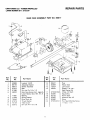
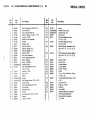
REPAIR PARTS
CRAFTSMAN
22'" POWER-PROPELLED
LAWN MOWER
917.372330
GEAR CASE
ASSEMBLY
PART
NO. 86617
17
!5
14
1
/
22
Ref.
No.
Part
No.
Ref.
No.
Part Name
1
2
3
4
5
6
53838
85178
86613
57072
57388
48032
Locknut 1/4-20
Adjusting
Bracket
Shifter Assembly
Seal
Driv-Lok Pin 1/8 x 1/2
Gear Case Halves (Incl. Upper &
Lower Halves) (Incl. Ref, # 4,7)
7
8
9
10
11
12
77881
77039
79946
57079
75144
53912
Bearing
Spring Bracket
Drive Shaft Kit
Thrust Washer
Yoke Clutch
Driv-Lok Pin I '8 x 5;8
!7
Part
No.
Part Name
13
14
15
16
86447
83659
75424
58354
Plug
Helical Gear
Jaw Clutch
Grease (1 lb. can Shell Darina AX)
17
18
19
20
21
22
STD581050
83684
83720
65692
83680
STD522512
E-Ring 112 Shaft
Square Key
Worm Shaft
Woodruff
Key #3
Worm
Hex Head Machine
14-20x
1 14
Screw
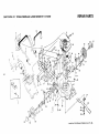
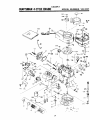
CRAFTSMAN
22 '° POWER-PROPELLED
LAWN
MOWER
REPAIR PARTS
917.372330
75
8
5
58
56
57
!
17
5_
/
\
2O
13
49
\
74
29
\
47
53
34
22"
11
37
33
\3
35
22
48
49
57
53
\
58
L.
\56
" BLADE NUT TIGHTENING
TORQUE 50-65
FT. LBS.
;_r_AFTSk,._N
Ref,
No.
22"
POWER-PROPELLED
Part
No.
LAWN
MOWER
Ri:PAIh PARTS
917.37..J30
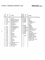
Ref.,
Part Name
No. J
Part
No.
I
!
2
3
4
5
6
7
8
9
10
11
12
13
85755
84683
86993
87269
53490
48053
58714
48052
8b_z/
85424
85529
85825
85436
Upper Handle
Lower Handle
Zone Engine Control
Machine Screw 1/4-20
x 2 3/16
Locknu ÷ 1/4-20
Zone Control Cable Ki_
Handle Bolt
Zone Cnntrol Head Kit
L,ontrol L,aole (;lID
Trim Plate
Nylon Bushing
Self-Tapping
Screw lO-24 x 1
Rex Washe_: Head Machine Screw
1/420
x 1 1/2
Locknut
1/4-20
Bracket Rope Guide:ISee
Parts List). (Source t43)
14
15
53490
34372A
16
17
.18
19
51793
77524
81027
77526
Hairpin Cotter
Rear
Door
=
=
,
20
21
22
77527
STD581025
STD512505
Spring
E:,Ring
Hex Head Tapping
1t4-20 x 1/2
Hinge
Hinge
83935
81281
85535
62363
79997
28
29
85463
3o ¸ ]
31
32
4.¸•
Engine
35
Screw
Door, Seal
63601
77514
81283
39
40
63601
STD511OO5
Handle Lever
Handle Knob
spri.g,Leve
_
.
_:
HousingAssembly
.(Incl. Ref #22,
:
.
:
28, 2go 30, 3!, 32;3&
Danger Decal : ;....
Back Plate
Back Plate Bracket
85371
STD512505
38
3:6:•
iii
85374
87267
85546
85354
86779
37.
Bracket
Rod
i
23
24
25
26
27
t
Part Name
34)
::
HexHead
Machine Screw,
1/4-20 x 1/2
........
Locknut 1/4:20
Side Baff e "
Hex Self-Tapping
10-24 x 3/8
,
,
,÷
Rear Skirt
Backing strip
Discharge Baffle
Hex =Head Machine
1/4;20 x 3/4
L()cknut 1/4-20
Truss
Screw
Head Screw
.
::.
Screw
10-24
X 112
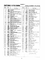
CRAFTSMAN
Ref.
No.
22"
POWER-PROPELLED
" Parl
No.
Par!
LAWN
MOWER
REPAIR PARTS
917.372330
Ref_
No.
Name
Par!
No.
Par!
-
41
42
43
44
45
46
O
47
48
49
50
51
52
53
54
5 5
5 6
5Z
58
59
60
61
6:2
63
64
69180
86915
86914
STD533107
63124
55187
86931
86933
87121
86929
77865
84920
62335
84921
74400
86870
.52160
55015
86918
70385
81276
75449
51433
54867
Locknut 10.24
Handle Bracket Assembly
Handle Bracket .Assembly
Cardage Bol t 5/16-18
Locknut 5L16-18
Thread Cu{ting Screw
5/t6
18 x 3/4
Wheel Adjusting
(Right)
(Left)
x 5/8
Bracket (L.R.)
Wheel Adjusting
Bracket
Axle Arm Assembly
Selector Spring
Selector Knob
(R.R.)
69
7O
71
72
73
74
75
76
Spacer
Spring Washer
Shoulder Bolt
Locknut 3/8-16
WheeI&
Tire.Assemlby
Washer
Retainer Clip,
Hub Cap (Rear)
Cable Clip
,Seff-Tapping
Screw
65
66
.67
68
69385
69334
84918
,68205
83629
85543
STD 58 O019
83813
STD502502
_63688 .......
"86814
i_b844
87000
Name
-:
•
•l• = i
Washer
Blade
Spee d Nut 10-24
Locknut 518-18 (Special)
Washer - S_ring
x 1/2
I
Blade .Flange,
Hex Head' Machine
5/t' 6-18
x 7/8
i
,,,I
Screw
(Special)
Belt Snubber
Engine =Pulley
Woodruff
Key #6
Hex Head Screw 10-32 x 5/16
, Set Screw-I!4-20
x 5/16
Handle Knob
Control Bar w/grip
Engine
Assembly
143.374132
(See Page 24 thru 26:)
=;Owners
Manual -Parts List
Hig h Wheel Kit (Not Included)
See Mode! Z! 33721
iLeaf
Catcher
(Not
Included
.
?i'
iiIll"
"
wZmower)
10-24
•
]t__ 33411
.
=
,
,
(CONT'D)
[
LAWNMOWERCARERECORD
NOTE: Change Engine OiJ after the first two (2) hours
DATE
Changed Oil 10W30
or SAE 30
Replaced
spark plug:
Replaced
air filter:
Replaced
blade:
Tuned-up:
r ,,
of
use,
and then every 25 hours of use.
DATE
DATE
CRAFTSMAN
22 °' POWER-PROPELLED
LAWN
MOWER
REPAIR PARTS
917.372330
I
8
6
52
49
\
I
2O
46
\
22
21
17
h3
14
. \
15
ti
,_
42
16
13
\
i
iI
/
20
I
12
21
B
k
-30
--31
19
27
_'_AFTSh,
J 22"
POWER-PROPELLED
Part
No.
Ref.
No.
I
PG
II
LAWN
MOWER
917.
Part Name
86992
48056
48057
87269
53490
86955
52160
55015
86917
86939
86937
77865
86946
86941
86273
86274
STD582087
61528
19
20
21
22
23
24
25
26
27
28
29
30
31
63601
76401
74507
STD581050
STD631003
83700
48031
83681
74976
83691
54338
83632
68038
REPAIK PARTS
,30
Ref.
No.
Part
No.
i
I
1
2
3
4
F
6
7
8
9
10
11
12
13
14
t5
16
17
18
33
Drive Control (Incl. Ref #2,3)
Drive Head Kit
Drive Control Cable Kit
Machine Screw 1/4-20 x 2 118
Locknut 1/4-20
Wheel & Tire Assembly
Washer
Retainer
Hub Cap
Selector
Selector
Selector
Clip
(Front)
Spring (R.F.)
Spring (L.F.)
Knob
Axle Arm Assembly
Wheel Adjusting Bracket
Spacer Bearing
Spring - Washer
Retaining Ring
Flat Head Machine Screw
1/4-20 x 3t4
Locknut
1/4-20
Dust CoveF
Pinion
E-Ring
Self-Tapping
Screw 10 24 x 3/8
Cable Clamp
Gear Case Replacement
Kit
Drive Pulley
Retaining Ring
V-Belt
Hex Head Bolt 1/4-20 x 2 314
Spring
Locknut
1/4-20
3i
Part Name
,,,,,,,,,,,,,,,,,,
,,,,
33
34
35
36
75192
STD580009
STD580014
83590
69411
37
75725
38
48054
39
48055
40
41
42
43
44
45
46
84806
87251
84164
83548
86968
83553
86988
47
83555
48
49
50
51
52
69180
53838
86963
85283
85878
iiiiiiiiiiii
Spring
Woodruff Key #213
Woodruff Key #3
Drive Cover
Pan Head Machine Screw
10-24 x 1 3/4
Pan Head Machine Screw
10-24x 2 3t4
Wheel Adjuster Assembly (Left)
(Incl. Ref # 11, 13, 14, 15, 16,
17)
Wheel Adjuster Assembly (Right)
(Incl. Ref # 10, 13, 14, 15, 16,
17)
Catcher Frame
Catcher Top
Catcher Bottom
Catcher Baffle
Catcher Handle
Clamp
Truss Head Machine Screw
1/4-20 x 3/4
Truss Head Machine Screw 10-24
x 5/8
Locknut 10-24
Keps Nut 1/4-20
Stifferner
Front Baffle
Clipping Deflector Accessory
(Not Included W/Mower)
Grass Catcher Complete
7._$1
33463
HIIII II
EAGER-1
CRAFTSMAN
4-CYCLE
ENGINE
MODEL
NUMBER:
IN
107----_
I
I
51
24
_
_13o
|
I06-_(_
173
143.3741,
IIII li
_
171
EAGER-1
CRAFTSMAN
4-CYCLE
ENGINE
I Ref.
Part
No.
NO.
1
6
5
6
9
10
11
12
!4
14
14
14A
14A
14A
!5
15
15
16
17 <
18
21
22
24
25
....
_
j
36
4!
I
'
47
49
: 5! :.'
i
_
;
30200
Screw, Hex washer hd. Sems, selftapping, 10-24 x 9/t6
Spring, Compression
Spring, Compression
•
. :Screw;.Fi!.
hd, 6-32 x 17/32
Screw, FiL hd., 5-40 x 7/16
Control Assy., Speed (Incl. Nos. 72,
.73, 74 8 75)
Link, :Governor-to-throttle
:; Wire, Ground;
Gasket, Carburetor
Screw, .Hex hd., t ,4-28 x 7/8
Nut 8. Lockwasher,
1/4-28
Cover, Air cleaner. "
Collar, Air cleaner
".Filter,. Air cleaner
i=Clamp, Air cieaner
_ Air Cleaner Kit. (incl. Nos. 91 thru 94!
52
5,3
55
56
57
5.9
60
62
66
7O
{
33802
31342
650777
650549
33205A
34-336
34961
*26756,
6201
29752
35065
35067
35066
35068
; ii,
143.374132
P_tName
26727
' 4:
26
27
28
30
31
Cylinder Assy: (Incl. Nos. 3 Et 4)/_
Pin, Dowe!
Seal, Oil
29314B
Valve, Intake (Std,)iinct.
No. 10)
293t5c Valve, tntake (1/32" oversize) (Incl.
No, t0)
_29313C
Valve, Exhaust (Std.)(Incl. NO, 10)
29315C
Valve,
Exhaust
(1132"
oversize)
(Incl. No. 10)
31672
Spring/Valve
'
31673
Cap; Lower valve spring
35175
Crankshaft
,.
32323
Washer, Thrust
34851
Piston,
Pin 8. Ring Assy. (Std.) (lncl.
i Nos. 14A, 15 8. !6)
Piston, Pin 8. Ring Assy. (.010 oversize) (Incl. Nos. 14A, 15 8" 16)
348.53
Piston, Pin 8- Ring Assyi (.020 oversize) (incl. Nos. 14A, !15 8. t6)
'Piston 8.Pin Assy,:(Std.)
(Incl, No, i6)
Piston 8. Pin AsSy.:(.010
oversize)
, (Incl. N0. 16)
Piston 8. Pin Assy. (.020 Oversize)
(Incl. No. 16)
34854
Ring Set, Piston (Std.)
_'
34855
Ring Set, Piston (.010 oversize)
34856. Ring Set, Piston (.020 oversize)
20381
Ring, Piston pin retaining
30963B Rod Assy. Connecting.(Incl: No; t8)
326!0A
Screw, Connecting rod
27241
Lifter, Valve
33553
Camshaft
(Mech.
Compression
Release)
............ , .............
299t4 " Pump Assy., Oil
*35261
Gasket, Mounting flange
34311B
Flange Assy., Mounting (Incl. Nos. 26,
27, 28 8. 32)
27897
Seal, Oi!
*28833
Gasket, Oil drain plug
30572
Plug, Oil drain
Screw, Hex hd, Seres, 1/4-20 x 1-1/4
30590A Washer, Rat
3O574
Shaft, Mechanical governor
3O591
Gear Assy., Governor {Incl. No. 31_
29193
Ring, Retaining
30588A : Spool Governor
31335
Clamp, Governor lever
3O589
Rod, Governor (Incl. No. 38)
28277
Washer, Flat
31383A Lever, Governor
31361
Spring, Governor i
650548
Screw, Hex washer hd., 8-32 x 5"16
611004
Key, Flywheel (Solid State)
"33015
Gasket, Cylinder head
34342
Head, Cylinder
6021A Screw, Hex flange hd., 5.,16-18 x 1-i,2
35395
Resistor Spark Plug (Champion
R J19LM or equivalent)
,27234
Gasket, Valve spring cover
32755
Cover, Valve spring box
3020O
Screw,
Hex washer hd. Seres, self_apping< 1024 x 9 16
34215
Breather Assv. dncl. Nos. 54 Et 56)
Gasket. Breather
"32760
650128
"34690
Gasket, Intake pipe
31384A
Pipe. Intake {Incl. No 59)
650451
Screw
Hex hd. Seres. 1 4 20 x !
FiI. hd. Sems. 10-24 x 1 2
2646o i Screw.
C!amp. Fuel line
:....
34&37
Link. Governor spring
I
NUMBER:
Part
No.
Part Name
35180
3
.
MODEL
3331
28763
:i Screw, Hex washer hd, shake-proof,
10:32 x 19.32
! Housing, Blower
Screw,
Hex washer
hd. Powerlok
thread, t 4-20 x t 2
30200
'.'Screw,
Hex washer hd, Seres, self' tapping. !0-24 x 9 t6
34369A Tank Assy.. Fuel Ilncl. No. 1021
35355
Cap, Fuel _ank
,:
35480
Retainer, Fuel cap
-650815 .... Washer, Belteville...
-:......
650816
Nut, Flywheel
35000
Hub, Starter
30705:
Line, :Fuel
-:_ : __: .......
....32410
Knob, Control ..........
35176
Cover, Control
650807
Screw,
Hex washer
hd. shoulder,
10-32 x 7 16
3444,3A
Solid State Assy.
1650814
Screw, Hex hd. Seres, t0-24 x !
35172
Muffler
650869
Screw. Hex hd.. 1 4-20 x 2-3 4
35171
Plate, Lock.
650562
. Screw. Hex wast_er hd shake-proof.
!0-32 _ ' 2
34265
Gasket
#i1! tilde
35393
650831
t :.:'
102
t03
_06,
107
108
110
114
1 !5
1t6
I
1t8
1! 9
120
_ 121
. 122
i:' t23
124
125
126
127
128.
129
130
131
135
136
137
t41
t42
t43
144
145
146
157
',70
',.-"t
I,
1
j
!
•
t
1
i
}
33590
34267
35_68
34264
34985
35392
550884
610118
3408C
6iI046A
=35015A
34965
34966
!32309
34968
610973
650839
63238£
59062:
: 332368
:
Tuoe Assv.: Oi! filler
:::
"0
Ring
Dipstick
0:I 'tnc'.. No. 126:
B-acket Ass',.., Rope gu.de
Retaire_
Sta_er .'Gee
Piug. Start.er
Screw
Hex washer hal,. 8-32 × 1 2
Co_er. Spark plug
S_acer Ftvwneel ke_,
Bracket Ass_. Brake
Sor_ng E_tens,oq
L.nk Control
R=n9 Reta,m_g
Le_er Srake
Ter'-,_a_ 3,ss_,
S:re_
_.e_ "d serf ta_ Seres
x7 '6
S : 3":,e"
" "',"
173
i
t
f
......................................
j_ ...............................
25
2_sD',
Gas-,e: Se:
,:._,:es
!
' 4-20
'R ew,n,.2
:r-,:
"_3"t_
:e:-'s mar,,ec
_C't'de'3
.r,
*
.
CARBUREIOH
m
NU.
(=_:i,_,.i_b
I
I
I
I
I
Ref.
No.
14
15
|
I
llm
Part
No.
1
3
4
5
6
7
9
11
12
632389
631615
631616
650506
631767
631971
631184
632O47
631027
631021
13
14
15
16
21
22
25
26
631022
632019
631024
631700
631334
631935
631028
631775
[
REWIND
|
STARTER
lllmm
Part Name
I
16
II
Carburetor
Shaft _ Lever Assy., Throttle
Shutter, Throttle
Screw, Throttle shutter
Spring, Throttle return
Seal, Dust
Washer, Flat
Primer Assy.
Plug, Welch
In(et Needle, Seat 8- Clip Assy.
(Incl. No. 13)
Clip, Inlet needle
Float, Carburetor
Shaft, Float
Bowl, Float
Gasket, Bowl-to-body
Nut, Float bowl
Gasket, Bowl-to-body
Fitting, Fuel inlet
NO. 590621
i
. m=
Ref.
2....
NO.
"-"_
12------;
-
Part
)
No.
(
Part
Name
!
"
1
2
3
4
5
6
7
8
9
.10
_ /_---_10
11
7 -----_Z
6-----"
-_ 2
2%
26
590621
5905,99
590600
590615
590601
590598
590616
590617
_18
590619
590620
590622
590535
i
Starter, Rewind
] Pin, Spring
mWasher
_ Retainer
} Washer
t Spring, Brake
( Dog, Starter
/ Spring, Dog
! Pulley
_ Spring, Rewind
i Cover, Spring
i Housing Assy., Starter
i Rope, Starter (Length 98" _f 9/64"
dia.)
5..90452
Hand e, Starter
LAWNMOWERCARERECORD
NOTE: Change Engine Oit after the-first two (2) hours of use, and then every 25 hours of use.
DATE
DATE
Changed Oil 10W30
or SAE 30
Repfaced
spark
plug:
Replaced
air filter:
,| •
Repraced
bfade:
,,,,,
Tuned-up:
27
DATE
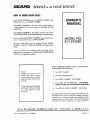
5ERWCE.is at YOUR SERVICE
HOW TO ORDERREPAIRPARTS
OWNER'S
MANUAL
Each LAWN MOWER has its own MODEL NUMBER. Each
ENGINE has its own MODEL NUMBER.
The MODEL NUMBER for the lawn mower will be found on
a plate attached to your lawn mower at the REAR OF THE
HOUSING.
The MODEL NUMBER for tile engine will be found on the
BLOWER HOUSING of the engine adjacent to the spark plug.
MODEL NO.
Always mention these MODEL NUMBERS when requesting service or repair parts for your LAWN MOWER.
917.372330
All parts listed herein may be ordered through SEARS,
ROEBUCK AND CO. SERVICE CENTERS and most Retail
Stores.
if parts you need are not stocked Iocaity your order will be
electronically transmitted to a SEARS PARTS DISTRIBUTION
CENTER for expedited handling.
WHEN ORDERING REPAIR PARTS, ALWAYS
FOLLOWING INFORMATION:
Serial
Number
,.
Model and Serial Number
GIVE
1. The PART NUMBER
2. The PART DESCRIPTION
may be found on the number
plate on the rear of the mower
housing.
3. The MODEL NUMBER - 917.372330
4. The NAME OF THE PRODUCT - CRAFTSMAN
POWER-PROPELLED REAR BAGGER LAWN MOW'
You should record both Model
and Serial Number and keep
in a safe place for future
reference.
5. The ENGINE
MODEL NUMBER - 143.374132
Your Sears merchandise has added value when you con:
that Sears has service units nationwide staffed with Sears t
ed technicians...professionol technicians specifically train_
Sears products, having the parts, tools and the equipme
insure that we meet our pledge to you, we service what w_
SOLD
BY SEARS,
ROEBUCK
I
Part No. 87000
Rev. 0
05/26/86
II
AND
CO.,
I
CHICAGO,
I
I
IIII II
IL 60684
U.S.A
Ill
Printed
in L