1
!
i
]
i illllll,i
i
,
,,ll iu
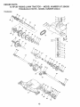
OWNER'S
MANUAL
MODEL NO.
917.254530
®
12.0 HP RC
ELECTRIC START
38" MOWER DECK
5 SPEED TRANSAXLE
LAWN TRACTOR
Caution:
Read and follow
all Safety Rules
and Instructions
Before Operating
This Equipment
• Assembly
. Operation
, Maintenance
° Service and Adjustment
o Repair Parts
i
iii
i
ii
i
i i
ill iiill IllIHll
I I II, II ,,_ LJ ,JJL,,IU,I.,I
Sears, Roebuck and Co., Chicago, IL 60684 U.S.A.
IIIH,,I,I
SAFETY RULES
CAUTION: ALWAYS D!_CONNECT SPARK PLUGW!RE AND PL&.CEWIRE WHERE !T CANNOT CONTACTSPARK
PLUG TO PREVENT ACCIDENTAL STARTING WHEN SETTING-UP, TRANSPORTING, ADJUSTING OR MAKING
REPAIRS°
'_
IMPORTANT
SAFETY STANDARDS REQUIRE OPERATOR PRESENCE CONTROLS TO MINIMIZE THE RISK OF INJURY, YOUR UNIT IS EQUIPPED WITH SUCH
CONTROLS. DO NOT ATTEMPT TO DEFEAT THE FUNCTION OF THE OPERATOR PRESENCE CONTROLS UNDER ANY CIRCUMSTANCES.
TRAINING:
Know the controls and how to stop quickly. Read this owner's
manual and instructions furnished with attachments°
Do not allow children to operate the machine, Do not allow
adults to operate it without proper instruction_
Do not carry passengers. Do not mow when children and
others are around.
Do not attempt tooperate your vehicle or mower when not in
the driver's seat.
Always get on or off your vehicle from the operator's left hand
side..
The vehicle and attachments shouid be stopped and in*
spected for damage after striking a foreign object, and the
damage should be repaired before restarting and operating
the equipment
•
•
•
•
•
•
.
PREPARATION:
•
•
,
•
Always wear substantial footwear Do not wear Ioose fitting
clothing that could get caught in moving parts
Clear the work area of objects (wire, rocks, etc.) which might
be picked up and thrown_
Disengage all attachment clutches before attempting to start
the engine,
Handle gasoline with care - it is highly flammable.
Use approved gasoline containers.
Never remove the fuel cap of the fuel tank oradd gasoline
to a running or hot engine or an engine that has not been
ailowed to coot for several minutes after running Never
fill tank indoors. Always clean up spilled gasoline.
Open doors if the engine is run in the garage * exhaust
fumes are dangerous, Do not run the engine indoors
Do not operate the mower without the entire grass catcher,
on mowers so equipped, or the deflector shield in place
•
°
•
•
•
OPERATION:
•
•
•
•
•
•
•
•
Keep your eyes and mind on your vehicle, mower, and the
area being cut. Do not let other interests distract you.
Disengage power to attachments and stop the engine before
leaving the operator's position.
Disengage power to mower, stop the engine, and disconnect
spark plug wire(s) from spark ptug(s) before cleaning, making
an adjustment, or repair., Be careful to avoid touching hot
muffler or engine components.
Disengage power to attachments when transporting or not in
use.
Take all possible precautions when leaving the vehicle unattended. Disengage the power take-off, lower the attachments, shift into neutral, set the parking brake, stop the
engine, and remove the key
Do not stop or start suddenly when going uphill or downhill.
Mow up and down the face of slopes (not greater than 15°),
never across the face,
Reduce speed on slopes and make turns gradually to prevent
tipping or loss of control Exercise extreme caution when
changing direction on slopes.
Whi_e going up or down slopes, place gearshift control lever
in t st gear position to negotiate the slope without stopping.
Never mow in wet or slippery grass, when traction is unsure,
or at a speed which could cause a skid,
Stay alert for holes in the terrain and other hidden hazards.
Keep away from drop-offs.
Do not drive too c{ose to creeks, ditches, and public highways,
Exercise special care when mowing around fixed objects in
order to prevent the blades from striking them. Never deliberately run vehicle or mower into or over any foreign objectso
Never shift gears until vehicle comes to a stop.
Never place hands or feet under the mower, in discharge
chute, or near any moving parts while vehicle or mower is
running. Always keep clear of discharge chute
Use care when pulling Ioads or using heavy equipment.
Use only approved drawbar hitch points.
Limit loads to those you can safely control.
Do not turn sharply. Use care when backing..
Use counterweight or wheel weights when suggested in
owner's manual.
Watch out for traffic when crossing or near roadways
When using any attachments, never direct discharge of
material toward bystanders nor allow anyone near the vehicle while in operation,r
Except for adjustments, do not operate engine if air cleaner
or cover directly over carburetor air intake is removed.
Removal of such part could create a fire hazard.
Do not change the engine governor settings or overspeed
the engine; severe damage or injury may result.
When using the vehicle with mower, proceed as follows:
Mow only in daylight or in good artificial light
Shut the engine off when unclogging chute.
Check the blade mounting bolts for proper tightness at
frequent intervals
Disengage power to mower before backing up.. Do not mow
in reverse unless absolutely necessary and then only after
careful observation of the entire area behind the mower,
MAINTENANCE
•
o
•
•
•
•
AND STORAGE
Keep the vehicle and attachments in good operating condi.
tion, and keep safety devices in place and working.
Keep all nuts, bolts, and screws tight to be sure the equip.
merit is in safe working condition.
Never store the equipment with gasoline in the tank inside a
building where fumes may reach an open flame or spark,.
Allow the engine to cool before storing in any enclosure.
To reduce fire hazard, keep the engine free of grass, leaves,
or excessive grease. Do not clean product while engine is
running.
Do not operate without a muffler, or tamper with exhaust
system° Damaged mufflers or spark arresters could create a
fire hazard, Inspect periodically and replace if necessary
Under normal usage the grass catcher bag material is
subject to deterioration and wear. It should be checked
frequently for bag replacemenL Replacement bags should
be checked
to ensure compliance
with the original
manufacturer's recommendations or specifications,
I
A
LOOK
FOR THIS
SYMBOL
IT
MEANSATTENTION]!!
,i,li ......................
TO
POINT
BECOME
OUT IMPORTANT
ALERT]!!
YOUR
,,
SAFETY IS PRECAUTIONS_
SAFETY
INVOLVED_
,
i,, ,,_.......
i===z_=a_=J
!
PRODUCT
CONGRATULATIONS
on your purchase of a Sears
Tractor. It has been designed, engineered and manufactured to give you the best possible dependability and
performance.
Should you experience any problem you cannot easily
remedy, please contact your nearest Sears Service
Center/Department
We have competent, wel!-trained
technicians and the proper tools to servtce or repair this
unit
Please read and retain this manual. The instructions will
enable you to assemble and maintain your unit properly.
Always observe the "SAFETY RULES",
MODEL
NUMBER
917.254530
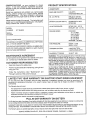
SPECIFICATIONS
HORSEPOWER:
12 0
GASOLINE CAPACITY:
5 QUARTS
UNLEADED REGULAR
OIL (3-0 PINTS):
SAE 30 (or 10W-30)
WINTER: SAE 5W-30
SPARK PLUG (GAPe025IN.):
CHAMPION RJ-19LM
STD361458
VALVE CLEARANCE:
INTAKE .005 * 007 IN
EXHAUST .009 - .011 IN
GROUND SPEED:
FORWARD
1st 1 10 MPH
2nd 2 00 MPH
3rd 3.00 MPH
4th 4 20 MPH
5th 5.00 MPH
REVERSE: 1.50 MPH
TIRE PRESSURE:
FRONT; 14 PSi
REAR: 10 PSI
CHARGING
3 AMPS BATTERY
5 AMPS HEADLIGHTS
SERIAL
NUMBER
DATE OF PURCHASE
THE MODELAND SERIAL NUMBERS WILL BE FOUND
ON A PLATE UNDER THE SEAT
YOU SHOULD RECORD BOTH SERIAL NUMBER AND
DATE OF PURCHASE AND KEEP 1N A SAFE PLACE
FOR FUTURE REFERENCE.
SYSTEM:
BLADE BOLT TORQUE:
MAINTENANCE
AGREEMENT
WARNING; This unit is equipped with an internal combustion engine and should not be used on or near any unimproved forest-covered, brush.covered or grass-covered
land unless the engine's exhaust system is equipped with
a spark arrester meeting applicable local or state laws (if
any), If a spark arrester =sused, it should be maintained in
effective working order by the operator,
A Sears Maintenance Agreement is available on this prod s
uct Contact your nearest Sears store for details.
CUSTOMER
RESPONSIBILITIES
•
Read and observe the safety rules.
,
Fellow a regular schedule in maintaining, caring for and
using your unit.
°
Follow the instructions
under "Maintenance"
30-35 FT. LBS
In the state of California the above is required by law
(_Section 4442 of the California Public Resources Code)
Other states may have similar laws, Federal laws apply on
federal lands. A spark arrester for the muffler is available
through your nearest Sears Authorized Service Center
(See REPAIR PARTS section of this manual)_
and
"Storage" sections of this owner's manual.
=lu,
LIMITED TWO YEAR WARRANTY
ON ELECTRIC
i
u,i,
=1,1,, ,,muu,,=
START RIDING EQUIPMENT
For two years from date of purchase, when this ddfng equipment is maintained, lubricated, and tuned up according to the
operating and maintenance instructionsin the owner's manual, Sears will repair free of charge any defect in material or
workmanship.
This Warranty does not cover:
,
Tire replacement or repair causedby punctures from outside objects (such as nails, thorns, stumps, or glass).
Expendable items which become worn during normal use, such as blades, spark plug, air cleaners and belts
Repairs necessary because of operator abuse or negligence, including bent crankshafts and the failure to maintain the
equipment according to the instructions
containedin the owner's manual
•
Riding equipment used for commercial or rental purposes.
FULL 90 DAY WARRANTY
ON BATTERY
For 90 days from date of purchase, if any battery included with this riding equipment proves defective in material or workmanship
and our testing determines the battery will not hold a charge, Sears will replace the battery at no charge,
WARRANTY SERVICE IS AVAILABLE BY CONTACTING THE NEAREST SEARS SERVICE CENTER/DEPARTMENT IN THE
UNITED STATES. THIS WARRANTY APPUES ONLY WHILE THIS PRODUCT IS IN USE IN THE UNITED STATES.
This Warranty gives you specific legal rights, and you may also have other rights which vary from state to state
SEARS, ROEBUCK AND CO, D/731CR-W SEARS TOWER, CHICAGO, IL 60684
3
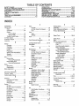
TABLE OF CONTENTS
OPERATION ...........................................................
MAINTENANCE ......................................................
SERVICE AND ADJUSTMENTS ............................
STORAGE ....................................................................
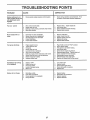
TROUBLESHOOTING
............................................
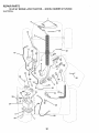
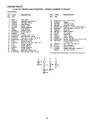
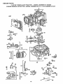
REPAIR PARTS - TRACTOR .................................
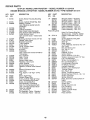
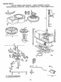
REPAIR PARTS - ENGINE .....................................
PARTS ORDERING/SERVICE ................... BACK
SAFETY RULES ............................................................
2
PRODUCT SPECIFICATIONS ....................................... 3
CUSTOMER RESPONSIBILITIES
................................ 3
WARRANTY ...................................................................
3
TABLE OF CONTENTS .................................................
4
INDEX .............................................................................
4
TRACTOR ACCESSORIES ........................................... 5
ASSEMBLY ................................................................
7-9
10-13
!4-17
_8-24
25
26-27
30-43
44-48
PAGE
INDEX
Battery:
Charging ............................................ 8
Cleaning ..................................................
16
Installation ...................................... 9
Levels ........................................ 8,16
Preparation ...........................................
8
Starting with Weak Battery ..............
22
Storage ........................................... 25
Terminals ..........................................16
Belt:
Motion Drive
Removal/Replacement
Mower Blade Drive
RemovaltReplacement
Blade:
Type ...............................................................
12
Storage ......................................... 25
Fuse .....................................................
23
Repair Parts ..................................
H
Hood Removal/installation
Carburetor Adjustment ............................24
Controls, Tractor ..................................... t 0
Cutting Height, Mower ........................... 11
E
Electrical:
Interlocks and Relays .....................23
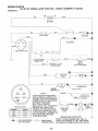
Schematic
29
Wiring Diagram .............................. 30
Engine:
Air Filter ......................................................
16
Air Filter Foam Pre-Cleaner ........ 16
Air Screen ..................................................
17
Cooling Fins, Engine .................... 17
Oi1Change .................................... 16
Oil Level ........................................12,16
Oil Type ........................................... 16
Preparation .................................. 12
Repair Parts ...................................
44-48
Starting .......................................... 13
Storage ...............................................25
.................. 23
L
Leveling Mower Deck .........................18-19
Lubrication:
Chart
14
M
Maintenance
14-17
Air Filter .......................................
16
Air Filter Foam Pre-Oleaner ......... 16
......................................
Air Screen, Engine ...................... 17
Battery ...................................................
16
Blade ..............................................................
15
Cooling Fins, Engine ..................... 17
Engine Oil .................................................
16
Fuel Filter ....................................
17
Lubrication Chart ......................... 14
Schedule ......................................... 14
........... 20
......................................
P
Parking Brake ...........................................
10-t 1
Parts Bag ..............................................
6
Parts, Replacement/Repair
............ 30-48
Product Specifications .......................................
3
..............21
Sharpening ..................................... 15
Replacement
15
Brake Adjustment ............................... 21
C
...........................................
F
Filter:
Air Filter ........................................ 16
Air Filter Foam Pre-Cleaner ............
16
Fuel .............................................
17
Fuel:
....................................................
..........................
A
Accessories .....................................................
5
Adjustments=
Brake ...........................................................
21
Carburetor .........................................24
Mower
Front-To-Back ..............................
19
Side-To-Side
18
Throttte Control Cable ................. 24
Air Filter, Engine ..................................... 16
Air Screen, Engine .............................. 17
Assembly .................................................7-9
B
Spark Plugs ................................... 17
Tire Care ......................................
8,15,22
Mower:
Adjustment, Front-to-Back ........... 19
Adjustment, Side-to-Side ............. 18
Blade Sharpening .............................15
Blade Replacement ..................... 15
Cutting Height ................................ 11
Installation ..................................
18
Operation ..............................................
12
Removal .................................................
18
Mowing Tips .................................................
13
Muffler
17
R
30-48
S
Safety Rules ............................................ 2
Se at ...................................................................
8
Service and Adjustments ...................
18-24
Carburetor .................................... 24
Fuse ............................................. 23
Hood Removal/Installation
..............
23
Motion Drive Belt
Removal/Replacement
...............
21
Mower Blade Drive Belt
Remova!/Replacement
........... 20
Mower Adjustment
Front- to-Back ........................ 19
Side-to-Side .................................18
Mower Removal ............................................
18
Tire Care ............................... 8,15,22
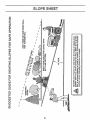
Slope Guide Sheet ......................................
51
Spark Plugs ...................................................
17
Specifications .................................................
3
Starting the Engine .................................
12-13
Steering Wheel ................................. 7,22
Stopping the Tractor ............................ 1t
Storage ........................................................................
25
T
Throttle Control Cable
Adjustment ................................... 24
Tires ................................................... 8,15,22
Trouble Shooting Chart .................. 26-27
Transaxle:
Repair Parts ........................... 42-43
W
............................................................
Spark An*ester ..............................3,34
O
Oil:
Cold Weather Conditions ........12,16
Engine ...............................................
16
Storage........................................ 25
Operation .............................................
10-t 3
Operating Mower .............................. _ol2
Options:
Accessories ........................................
5
Spark An*ester.................................
3,34
Warranty ...........................................................
3
Wiring Diagram ...........................................
30
i
........
i,iiiJ_=_,,
, ,,, ,r,llr
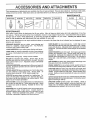
ACCESSORIES
.....................
iii
AND ATTACH
ENTS
i, i, i1,1,1,,,,i
These accessories and attachments were available when the unit was purchased, They are also available at most Sears retail outlets,
catalog and service centers. Most Sears stores can order these items for you when you provide the model number of your tractor
MAINTENANCE
ENGINE
SPARK PLUG
MUFFLER
AIR FILTER
GAS CAN
ENGINE OIL
STABILIZER
BLADES
BELTS
%
PERFORMANCE
Sears offers a wide variety of attachments that fit your vehicle. Many of these are listed below with brief explanations of how they
can help you. This list was current at the time of publication; however, it may change in future years - more attachments may be added,
changes may be made in these attachments, or some may no longer be available or fit your model
Contact your nearest Sears
store for the accessories and attachments that are available for your unit.
Most of these attachments
attaching and detaching
do not require additional hitches or conversion
PERMANEX BAGGER lets you collect grass clippings and
leaves for a healthier, neater looking lawn
Two Permanex
containers hold 30-gallon plastic bags
LAWN SWEEPERS
let you collect grass clippings and leaves
LAWN VACS for powerful collections of heavy grass clippings
and leaves Wand attachment to pick up debris in hard-to*reach
places
CARTS make hauling easy. Variety of sizes available.
ROLLER for smoother lawn surface.
36-inch wide, 18 inch
diameter water-tight drum holds upto 390 ibs of weight Rounded
edges prevent harm to turf Adjustable scraper automatically
cleans drum.
SPREADER/SEEDERS
make seeding, fertilizing, and weed killing easy. Broadcast spreaders are also useful for granular deicers and sand
CORING AERATOR takes small plugs out of soil to allow moisture and nutrients to reach grass roots
36-inch swath
24
hardened steel coring tips. I50 lb. capacity weight tray
AERATOR promotes deep root growth for a healthy lawn Tapered 25" steel spikes mounted on 10-in diameter discs puncture holes in soil at close intervals to let moisture soak in. Steel
weight tray for increased penetration.
DETHATCHER loosens soil and flips thatch and matted leaves to
lawn surface for easy pick up Twenty spring tine teeth. Useful
to prepare bare areas for seeding. Available for front or rear
mounting
SPRAYERS use 12-volt DC electric motor that connects to the
tractor battery or other 12-volt source
Includes booms for
automatic spraying when pulling, and hand held wand for spot
spraying.
Wand has adjustable spray pattern. For applying
herbicides, insecticides, fungicides, and liquid fertilizers
kits (those that do are indicated) and are designed for easy
SNOW BLADE for snow removal only 14-inch high, 42-inch
wide blade clears 38 inch path when angled left or right. Raises,
lowers with side lever Adjustable skids; replaceable, reversible
scraper bar. (Use with tire chains, wheel weights, or rear drawbar
weight.)
SNOWTHROWER has 40-inch swath. Drum-type auger handles
powdery and wet/heavy snow
Mounts easily with simple pin
arrangement. Discharge chute adjusts from tractor seat. 6-inch
diameter spout discharges snow 10 to 50 feet. Lift controlled at
tractor seat. (Use with chains, wheel weights, or rear drawbar
weight )
TIRE CHAINS are heavy duty; closely spaced extra-large cross
links give smooth ride, outstanding traction.
WHEEL WEIGHTS for rear wheels provide needed traction for
snow removal or dozing heavy materials tn pairs_ (30 lbs each )
TRACTOR CAB has heavy duty vinyl fabric over tubular steel
frame, ABS plastictop; clear plastic windshield offers 360 degree
visibility. Hinged metal doors with catch. Keeps operator warm
and dry. Remove vinyl and windshields for use as sun protector
in summer.
Optional accessories for tractor cab: tinted/tempered solid safety
glass windshield with hand operated wiper; 12-volt amber caution
light for mounting on cab top
TRACTOR COVER protects tractor from weather
Made of
Evolution 3 fabric (water-repellent, extremely breathable, light
weight, soft, non-abrasive, ptiable in all temperatures, durable,
stain/tear/puncture resistant, will not shrink or stretch).
, i. ,,,,,nIHlU"U
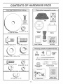
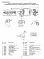
CONTENTS OF HARDWARE PACK
ii
, i,,,u
,i
Parts Bag contents
..... I
shown full size
, i
.......
i,,,i,1,,
,i,ii1,1
........... '
,i,, ,i
_ ,tll
Parts packed seParately
,.,
in carton .....................
Q
Seat
(2) Sheet
Metal
Screws
#10-16 x I/2
©
(1) Locknut
I/2 - 20
(1) 2_3/8" Diao Washer
Battery acid
Steering
Wheel
Battery
!©___ :
Steering
Boot
(1) Shoulder Bolt 5/16-18
@
(1) Washer
(1) Hex Bolt I/2-I3
x1
Owner's
Manual
Parts bag contents
(1) keokwasher
1/2
Steering
Bushing
Parts Bag
not shown full size
_
Wheel
Steering
Insert
(2) Keys
17/32 x 1-3/I6 x 12 Ga,
(2) Hex Bolts 1/4 - 20 x 3/4
(2) Battery Carriage
@
©
Steering Wheel
Adapter
Bolts 1/4-20 x 7-1/2
Terminal Guard
(2) Hex Nuts 1/4 - 20
_(2)Washers
9132 x 5/8 x 16 Ga. (2) Lockwashers
(2) Wing Nuts 1/4 - 20
1/4
15° Slope Sheet
Battery Caps
and Instructions
ii H
ASS
i
TOOLS
REQUIRED
ii1..
illlll
LY
i,i H,HH,IIH
ii 'l.l'._lrMl.I
FOR ASSEMBLY
INSERT
(1) 3/4" wrench
2-1/4" DIA. WASHER
(1) 1/2" wrench
Tire pressure gauge
Screwdriver
STEERING
(1) 9/16" wrench
Utility knife
(2) 7/16" wrenches
I I I I
1/2 - 20 HEX
A socket wrench set will make assembly easier. Standard
wrench sizes are fisted.
(1) 5/16" wrench
I
-.,.._
When right and left hand is mentioned in this manual, it
means when you are in the operating position (seated
behind the steering wheel).
TO REMOVE
UNPACK
STEERING
BUSHING
CARTON
•
Remove all accessible loose parts and parts cartons
from carton (See page 6).
•
Cut along dotted lines on carton, from top to bottom, all
four corners of carton and lay panels flat.
•
Check for any additional loose parts or cartons and
remove.
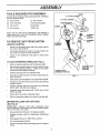
ATTACH
STEERING
WHEEL
(See Fig. 1)
•
Slide the steering bushing over the steering shaft.
•
Raise steering shaft forward until screw ho_es in dash
tine up with steering bushing.
Install two (2) sheet
metal screws and tighten securely.
•
Position steering boot over steering shaft,
•
Place tabs of steering boot over slots in dash and push
down to secure,
•
Slide steering wheel adapter onto upper steering shaft.
•
Position front wheels of the tractor so they are pointing
straight forward.
•
Position steering wheel so cross bars are horizontal
(left to right) and slide onto adapter.
•
Assemble large flat washer and 1/2-20 hex nut and
tighten securely
•
Snap insert into center of steering wheel.
•
Remove protective plastic from tractor hood and grit1.
BEFORE
STEERING
BOOT
UNW FROM CARTON
ROLLING
UNIT OFF SKID
(See Fig. 6)
IMPORTANT:
CHECK
FOR AND REMOVE
ANY
STAPLES IN SKI D THAT MAY PUNCTURE TIRES WHERE
UNIT IS TO ROLL OFF SKID.
•
Raise attachment {ift lever to its highest position.
•
Release parking brake by depressing
pedal
•
.
Place gearshift lever in "NEUTRAL"
Roil unit backwards off skid.
•
Remove banding holding discharge guard up against
tractor
clutch/brake
position.
\
STEERING
SHAFT
(SHIPPING
POSITION)
STEERING SHAFT
(ASSEMBLY POSITION)
FIG. I
ASSEM
LY
HOW TO SET UP YOUR TRACTOR
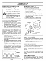
INSTALL
PREPARE
Adjust seat before tightening adjustment bolto
BATTERY
(See Fig. 2)
SEAT (See Fig. 3)
•
Remove cardboard packing on seat pan°
CAUTION; Wear eye and face shield.
•
Piace seat on pan and assemble shoulder bolto
Wash hands or clothing immediately if
accidentally in contact with battery acid.
•
Assemble adjustment bolt, lockwasher and flat washer
loosely. Do not tighten,
•
Tighten shoulder bolt securely,
•
Lower seat into operating position and sit on seat.
•
Slide seat until a comfortable position is reached
which allows you to press clutch/brake pedaI all the
way down (See Fig° 6),
•
Get off seat without moving its adjusted position,
•
Raise seat and tighten adjustment bolt securely_
Do not smoke. Fumes from charged
battery acid are explosive.
Read the instructions _ncluded with the
battery vent caps, Always wear gloves,
clothing and goggles to protect your
hands, skin and eyes.
Your unit has a battery charging system which is sufficient
for normal use, However, periodic charging of the battery
with an automotive charger will extend its life
•
See instructions packed with vent caps in parts bag.
•
Fill battery with acid. Fill each ce!l until it reaches the
bottom of the vent wells. Do not overfill
•
Ailow battery to stand and settle for at least thirty
minutes° After standing, check the level of acid. if
below the vent wells, add more acid until the correct
level is reached
SEAT
SEAT PAN
SHOULDER
BOLT
While battery is standing (after adding acid) and later, while
battery is being charged, continue with assembly of unit.
IMPORTANT:
TO MAXIMIZE THE LIFE OF YOUR
BATTERY, iT IS NECESSARY THAT THE BATTERY BE
CHARGED
BEFORE USE FAILURE TO CHARGE
BATTERY CAN RESULT IN A SHORTENED BATTERY
LIFE
.
FLAT WASHER
ADJUSTMENT
BOLT
Charge battery at a rate of 6 amperes for I hour. Use
a 12 volt battery charger Observe all safety precautions
required for battery charging.
.
Check the acid level after the battery is charged, If the
acid has fallen below the correct level, add distilled or
iron free water.
,
tnstali the vent caps to cover the vent wells. Wash the
top of the battery with water to remove any acid, then
wipe dry.
•
Check battery case for leakage to make sure that no
damage has occurred in handling.
,
Dispose of excess battery acid. Neutralize acid for
disposal by adding it to four inches of water in a five
gallon prastic container. Stir with a wooden or plastic
paddle while adding baking soda until the addition of
more soda causes no more foaming
•
Follow instructions on how to install battery°
CUT AWAY
!
VIEW
_
L..._.....J
VENT
LOCKWASHER
FIG. 3
CHECK
TIRE PRESSURE
The tires on your unit were overinflated at the factory for
shipping purposes. Correct tire pressure is important for
best cutting performance_
•
Reduce tire pressure to PSI shown in "PRODUCT
SPECIFICATIONS" on page 3 of this manual
CHECK
DECK LEVELNESS
For best cutting,results, mower housing should be properly
levele&
See TO LEVEL MOWER HOUSING in the
Service and Adjustments section of this manual,
CHECK
BELTS
FOR
PROPER
POSITION
OF ALL
See the figures that are shown for replacing motion and
mower blade drive belts in the Service and Adjustments
section of this manual
Verify that the belts are routed
correctly,
CAP
L-...-J
CHECK
BATTERY
CELL ACID
LEVEL
FIG. 2
,\
8
BRAKE
SYSTEM
After you learn how to operate your tractor, check to see
that the,, brake is properly adjusted. See "TO ADJUST
BRAKE in the Service and Adjustments section of this
manuaI,
===IHI=Ill
ASSEM
== H =,=l
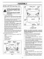
INSTALL
BATTERY
LY
=H
(See Figs. 4 & 5)
WING
NUT
TERMINAL
GUARD
ACCESS
DOOR
CAUTION: Do not short battery terminals. Before Installing battery, remove
metal bracelets, wristwatch bands,
rings, etc.
Positive terminal must be connected
first to prevent sparking from accidental grounding.
•
Lift seat to raised position.
•
Lower battery into fender well with battery terminals
toward front of unit. Make sure battery rests in battery
tray
,
Be sure battery drain tube has not come loose and is
securely attached to drain in battery tray.
•
First connect RED battery cable to positive (+) battery
terminal with hex bolt, flat washer, lockwasher and hex
nut as shown. Tighten securely.
•
Connect BLACK grounding cable to negative (-) battery terminal with remaining hex bolt, flat washer,
tockwasher and hex nut_ Tighten securely.
•
Slide the two battery bolts through the terminal guard
and start the wing nuts onto the threads
•
Position terminal guard over the battery as shown,
lower bolts into key holes and slide square shafts of
bolts into slots of key holes,
•
Tighten wing nuts by hand making sure battery bolts
remain in slots of the key holes in the battery support.
Be sure terminal access doors are closed.
•
Use terminal access doors for:
•
Inspection
ware).
for secure connections
BATTERY
BOLT
KEY
HOLE
BATTERY
DRAIN TUBE
FIG, 5
,[CHECKLIST
BEFORE YOU OPERATE AND ENJOY YOUR NEW
TRACTOR, WE WISH TO ASSURE THAT YOU RECEIVE
THE BEST PERFORMANCE AND SA TISFAC TION FROM
THIS QUALITY PRODUCT.
PLEASE REVIEW THE FOLLOWING
(to tighten hard-
BATTERY
TRAY
CHECKLIST:
¢"
Atl assembly instructions have been completed.
¢"
No remaining loose parts in carton.
v'
Batteryis properly prepared and charged.
1 hour at 6 amps).
°
Inspection for corrosion.
•
Testing battery,
•
Jumping (if required).
v"
Seat is adjusted comfortably
•
Periodic charging.
,/
All tires are properly inflated, (For shipping purposes,
the tires were over-inflated at the factory)
,/
Be sure mower deck is properly leveted side.to-side/
front-to-rear for best cutting results. (Tires must be
properly inflated for leveling)_
€"
Check mower and drive belts, Be sure they are routed
properly around pulleys and inside all belt keepers
POSITIVE (+)
TERMINAL
POSITIVE (RED)
CABLE
NEGATIVE ( - )
TERMINAL
NEGATIVE
(BLACK)
FLATWASHERS
CABLE
(Minimum
and tightened securely,
¢"
Check wiring, See that all connections are still secure
and wires are properly clamped.
WHILE LEARNING HOW TO USE YOUR TRACTOR, PAY
EXTRA ATTENTION TO THE FOLLOWING IMPORTANT
ITEMS:
HEX NUT
LOCKWASHERS
,,"
Engine oil is at proper level,
€"
Fuel tank is filled with fresh, clean, regular unleaded
gasoline.
Become familiar with all controls - their location and
function, Operate them before you start the engine.
HEX NUT
¢"
FIG_ 4
,/
Be sure brake system is in safe operating condition.
OPERATION
=
='HH
i
" '='1.....
,
,11,1
..... = =.H,,,,=....................................
KNOW YOUR TRACTOR
READ
THIS
OWNER'S
MANUAL
AND
SAFETY
RULES
BEFORE
OPERATING
YOUR
TRACTOR
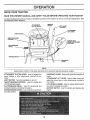
Compare the illustrations with your tractor to familiarize yourself with the locations of various controls and adjustments.
this manual for future reference.
Save
IGNITION
ATTACHMENT
CLUTCH LEVER
SWITCH
LIFT LEVER
PLUNGER
/
ATTACHMENT
LIFT LEVER
LIGHT SWITCH
THROTTLE/CHOKE
CONTROL
6_,t
"
MOWER DECK
HEIGHT ADJUSTMENT
POSITIONS
CLUTCH/BRAKE
PEDAL
!
J
J
PARKING
GEARSHIFT
LEVER
FIG. 6
Sears tractors conform to the safety standards of the American National Standards Institute_
ATTACHMENT CLUTCH LEVER: Used to engage the
mower blades, or other attachments mounted to your
tractor.
LIGHT SWITCH:
GEARSHIFT LEVER: Selects the speed and direction of
tractor.
ATTACHMENT
LIFT LEVER: Used to raise, lower, and
adjust the mower deck or other attachments mounted to
your tractor_
LIFT LEVER PLUNGER: Used to release attachment rift
lever when changing its position.
Turns the headlights on and off.
THROTTLE/CHOKE
CONTROL:
controlling engine speed,
Used for starting and
CLUTCH/BRAKE
PEDAL:
Used for declutching
braking the tractor and starting the engine.
and
IGNITION SWITCH:
engine,
PARKING BRAKE LEVER: Locks clutch/brake pedal into
the brake position.
10
Used for starting and stopping the
The operation of any tractor can result in foreign objects thrown into the eyes, which can
result in severe eye damage Always wear safety glasses or eye shields while operating
your tractor or performing any adjustments or repairs We recommend wide vision safety
mask for over the spectacles or standard safety glasses, available at Sears Retail or
Catalog stores
HOW TO USE YOUR TRACTOR
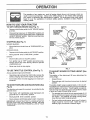
TO SET PARKING
BRAKE
IGNITION
(See Fig 7)
•
Depress clutch/brake pedal into full 'BRAKE" position
and hold
•
Place parking brake lever in "ENGAGED" position and
release pressurefrom clutch/brake pedal Pedal should
remain in "BRAKE" position Make sure parking brake
will hold vehicle secure
STOPPING
ATTACHMENT
CLUTCH LEVER
"ENGAGED"
POSITION
'DISENGAGED"
POSITION
THROTTLE/
CHOKE
CONTROL
LEVER
(See Fig. 7)
MOWER BLADES
•
Move attachment clutch lever to 'DISENGAGED'
sition
po-
"ENGAGED"
POSITION
POSITION
GROUND DRIVE
•
Depress clutch/brake pedal into full BRAKE"
•
Move gearshift
ENGINE -
lever to NEUTRAL"
position
position
"BRAKE"
POSITION
•
Move throttle control to SLOW'
•
Turn ignition key to 'OFF' position and remove key
Always remove key when leaving vehicle to prevent
unauthorized use
•
position
PEDAL "DRIVE"
POSITION
3EAR
SHIFT
LEVER
"CLUTCH"
POSITION
Never use choke to stop engine
FIG, 7
TO USE THROTTLE
CONTROL
(See Fig. 7)
TO ADJUST
Fig. 6)
Always operate engine at full throttle
MOWER
CUTTING
HEIGHT
(See
•
Operating engine at less than full throttle reduces the
battery charging rate and the engine cooling air flow
The position of the attachment
cutting height
•
Full throttle offers the best bagging and mower per
formance
•
Grasp lift lever
.
Press plunger with thumb and move lever to desired
position
TO MOVE FORWARD
Fig. 6)
AND BACKWARD
The direction and speed of movement
gearshift lever
(See
Start tractor with clutch/brake pedal depressed and
gearshift [ever in 'NEUTRAL" position
.
Move gearshift
lever to desired
the
The cutting height range is approximately 1-1/4 to 3-3/4"
The heights are measured from the ground to the blade tip
with the engine not running These heights are approxi
mate and may vary depending upon soil conditions, height
of grass and types of grass being mowed
is controlled by the
.
lift lever determines
•
The average lawn should be cut approximately 2-t/2
inches d uring the coot season and over 3 inches during
hot months
For healthier and better looking lawns
mow often and after moderate growth
•
For best cutting performance, grass over 6 inches in
height should be mowed twice
Make the first cut
relatively high; the second to desired height
position
•
Slowly release clutch/brake pedal to start movement
IMPORTANT: BRING TRACTOR TO A COMPLETE STOP
BEFORE SHIFTING OR CHANGING GEARS. FAILURE
TO DO SO WILL SHORTEN THE USEFUL LIFE OF YOUR
TRANSAXLE
11
OPERATION
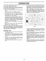
TO OPERATE
MOWER
(See Fig. 8)
Your unit is equipped with an operator presence sensing
switch. Any attempt by the operator to leave the seat with
the engine running and the attachment clutch engaged will
shut off the engine,
•
Select desired height of cut,
•
Engage mower by slowly moving attachment clutch
lever to "ENGAGED" position.
TO STOP MOWER- Move attachment clutch lever to
"DISENGAGED" position.
•
.
If stopping is absolutely necessary, push clutch/brake
pedal quickly to brake position and engage parking
brake°
•
Move gearshift lever to 'tst gear and be sure you have
allowed room for tractor to roll slightly as you restart
movement.
•
To restart movement, slowly release parking brake and
clutch/brake pedal.
•
Make al! turns slowly.
TO TRANSPORT
without either the entire grass catcher,
on
mowers Do
so not
equipped,
disCAUTION:
operate or
the the
mower
charge guard in place.
•
Raise attachment lift control to highest positiom
°
When pushing or towing your unit, be sure gearshift
lever is in "NEUTRAL" position,
.
Do not push or tow unit at more than five (5) MPH.
BEFORE
"ENGAGED"
CHECK
ATTACHMENT.CLUTCH
LEVER /
DISENGAGED
POSITION
7
,/
/J
/
A'I-rACHMENT
LIFT LEVER
HIGH POS|TION
J
STARTING
THE ENGINE
POSITION
LOW
ENGINE
OIL LEVEL
(See Fig, 16)
•
The engine in your unit has been shipped, from the
factory, aiready filled with summer weight oil,
.
Check engine oil with unit on level ground,
•
Remove oi! fill dipstick and wipe clean, replace and
screw cap tight, wait for a few seconds, remove and
read oil level If necessary, add oil until "FULL" mark
on dipstick is reached. Do not overfill
•
For cold weather operation you should change oil for
easier starting (see "OIL VISCOSITY CHART" in the
Maintenance section of this manual).
.
To change engine oil, see the Maintenance
this manual.
section in
ADD GASOLINE
•
IMPORTANT:
WHEN OPERATING IN TEMPERATURES
BELOW 32°F(0_C), USE FRESH, CLEAN WINTER GRADE
GASOLINE TO HELP INSURE GOOD COLD WEATHER
STARTING°
R.N_
RUNNER
WARNING:
Experience indicates that alcohol blended
fuels (called gasohol or using ethanol or methanol) can
attract moisture which leads to separation and formation of
acids during storage. Acidic gas can damage the fuel
system of an engine while in storage, To avoid engine
problems, the fuel system should be emptied before storage of 30 days or longer, Drain the gas tank, start the
engine and let it run until the fuel lines and carburetor are
empty, Use fresh fuel next season. See Storage Instructions for additional information.
Never use engine or
carburetor cleaner products in the fuel tank or permanent
damage may occur,
DISCHARGE
GUARD
FIG. 8
TO OPERATE
ON HILLS
hills with slopes greater than 15 _ and
CAUTION:
Do not drive up or down
do not drive across any slope.
filler neck. Do not overfill. Wipe off any
CAUTION:
spilled
oil orFill
fuel.to Do
bottom
not store,
of gas
spill
tank
or
use gasoline near an open flame.
Choose the slowest speed before starting up or down
hills,
o
Avoid stopping or changing speed on hills.
If slowing is necessary,
slower position.
Fill fuel tank° Use fresh, clean, regular unleaded
gasoline. (Use of leaded gasoline will increase carbon
and iead oxide deposits and reduce valve life).
move throttle control lever to
12
i
...............................
OPERATION
n i ...........................................
TO START
ENGINE
i
(See Fig. 7)
When starting engine for the first time or if engine has
run cut of fuel, it will take extra cranking time to move
fuet from the tank to the engine.
•
Depress the clutch/brake
brake.
.
Place gearshift lever in "NEUTRAL"
•
Move attachment clutch to "DISENGAGED"
•
Move throttle control lever to "CHOKE" position for
cold engine start,, For warm engine start, move
throttle control to "FAST" position.
•
iii i, ii,U,lU................................
Drive so that clippings are discharged onto the area
that has been cuL Have the cut area to the right of
the machine. This will result in a more even distribution of clippings and more uniform cutting,
When mowing large areas, start by turning to the
right so that clippings will discharge away from
shrubs, fences, driveways, et& After one or two
rounds, mow in the opposite direction making left
hand turns until finished (See Fig. 9).
pedal and set the parking
position°
position,
Turn ignition key clockwise to "START" position and
release key as soon as engine starts. Do not run
starter continuously for more than fifteen seconds
per minute, If engine does not start after several
attempts, move throttle control to "FAST" position,
wait a few minutes and try again,
•
When engine starts, move throttle control to desired
position_
•
Allow engine to warm up for a few minutes before
engaging drive or attachment clutch°
NOTE: If at a high altitude (above 3000 feet) or in cold
temperatures (below 32 ° F), the carburetor fuel mixture
may need to be adjusted for best engine performance.
See "TO ADJUST CARBURETOR" in the Service and
Adjustments section of this manual.
MOWING
FIG. 9
•
If grass is extremely tall, it should be mowed twice
to reduce load and possibfe fire hazard from dried
clippings. Make first cut relatively high; the second
to the desired heighL
TIPS
•
Tire chains cannot be used when the mower housing is attached to uniL
•
•
Mower should be properly leveled for best mowing
performance. See "TO LEVEL MOWER HOUSING"
m the Service and Adjustments
section of this
manual.
Do not mow grass when it is weL
plug mower and leave undesirable
grass to dry before mowing
•
Always operate engine at full throttle when mowing
to assure better mowing performance and proper
discharge of material,
Regulate ground speed by
selecting a low enough gear to give the mower
cutting performance as well as the quality of cut
desired_
•
When operating attachments, select a ground speed
that will suit the terrain and give best performance of
the attachment being used,,
•
Use the runner on the right hand side of mower as
a guide.
The blade cuts approximately
an inch
outside the runner (See Fig, 8).
•
The left hand side of mower should be used for trimming.
13
Wet grass will
dumps
Allow
MAHNTSNAN¢5
j Check Brake Operation
Check T_rePressure
V'
6_4
,,,,
T j check for Loose Fasteners
a I S, ,p
/Rop
Mower
Blades
e
_
, ,
!
1
v'
V _
0 I Clean Battery and Terminals
Vlf
I Adjust Blade Bel!,(s}Tension
t Adjust Moro_
n Dr'lye Belt(s) Tension ......
E
,,i,,
MY'
6_
N Clean Air Screen
G Inspect Muffler/SparkArrester
I
N
....
i
.....
Check Engine Oil Level
Change Engine Oil
Clean Air Filter
,_
-, ................. ,,
.......
V_2
.......
Replace Oil Filter (if equipped)
Glean Engine Cooling Fins
Replace Spark Plug
_..
...RePlaceAir Filter Paper Cartridge
Replace Fuel Filter
,,, ,,,,
...... ,V
_
v'
.........
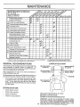
I - Change more often when operating under a heavy lead or in high ambient temperatures
2 - Service mere often when operating In dirty or dusty conditions
GENERAL
V e
3 - If equipped with oil filter, change oil even/50 hours,
4 - Replace blades more often when mowing in sandy self
RECOMMENDATIONS
LUBRICATION
The warranty on this vehicle does not cover items that have
been subjected to operator abuse or negligence,
To
receive full va_ue from the warranty, operator must maintain unit as instructed in this manual.
CHART
(_
(If equipped)
(If equipped)
(_) FRONT W_
BEARING ZERK
Some adjustments wilt need to be made periodically to
properly maintain your unit,
"FRONT WHEEl,. (_
BEARING ZERK
All adjustments in the Service and Adjustments section of
this manual should be checked at least once each season.
•
Once a year you should replace the spark plug, clean
or replace air filter, and check blades and belts for
wear, A new spark plug and clean air filter assure
proper air-fuel mixture and help your engine run better
and last longer.
BEFORE
@
CLUTCH PIVOT
EACH USE
•
Check engine oil level,
•
Check brake operation,
•
Check tire pressure,
"
Check for loose fasteners.
(_ SAE 30 OR 10W30 MOTOR OIL API - SFiCC
(_) GENERAL
PURPOSE
GREASE
(_) REFER TO ENGINE MAINTENANCE
14
SECTION
IMPORTANT:
DO NOT OIL OR GREASE
THE PIVOT POINTS
WHICH HAVE SPECIAL NYLON BEARINGS
VISCOUS
LUBRICANTS WILL ATTRACT
DUST AND DIRT THAT WILL SHORTEN
THE LIFE OF THE SELF-LUBRICATING
BEARINGS.
IF YOU
FEEL THEY MUST BE LUBRICATED
USE ONLYADRY,
POWDERED GRAPH TE TYPE LUBRICANT
SPARINGLY_
iii
,,
,,,t
Jl,
i,ii.,,i
t
, ,i
_
i
HI,,I
I1,,
, ,,,,, ..............,,.,,,
,UlH,,,,,.,_
U"
NTENANCE
= ,,,,...........................
,H ,,,,H,,HU
,,,,
,,,JH
,H
H
,,,,,,,
,H,,
,,HHH
,
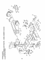
TRACTOR
MANDREL
Always observe safety rules when performing any mainteNance
_ACKSHAFT}
ASSEMBLY
BRAKE OPERATION
FLANGES
If unit requires more than six (6) feet stopping distance at
high speed in highest gear, than brake must be adjusted
(See "TO ADJUST BRAKE" in Service and Adjustments
section of this manual)
FLAT WASHER
LOCKWASHER
TRAILING
EDGE
TIRES
HEX BOLT
(GRADE S)*
UP
•
Maintain proper air pressure in aIl tires (See "PRODUCT SPECIFICATIONS" on page 3 of this manual)
•
Keep tiresfree of gasoline, oil, or insect control chemicals which can harm rubber.
*A GRADE 5 HEAT TREATED BOLT
CAN BE IDENTIFIED BYTHREE LINES
ON THE BOLT HEAD AS SHOWN AT
LEFT.
Avoid stumps, stones, deep ruts, sharp obiects and
other hazards that may cause tire damage.
BLADE
_,..
CARE
For best results mower blades must be kept sharp. The
blades can be sharpened with a file or on a grinding wheel.
We suggest they be sharpened or replaced after every 25
hours of mowing Check blades more often if mowing in
sandy conditions
FIG. 10
TO SHARPEN
BLADE
(See Fig. '11)
•
Do not attempt to sharpen blades while they are on the
mower,
Care should be taken to keep the blade balanced. An
unbalanced blade will cause excessive vibration and eventua! damage to mower and engine,
•
Replace bent or damaged blades
•
The blade can be sharpened with a file or on a grinding
wheel Do not attempt to sharpen while on the mower,
•
To check blade balance, drive a nail into a beam orwaII,
Leave about one inch of the straight nail exposed.
Place center hole of blade over the head of the nail. If
blade is balanced, it should remain in a horizontal
position If either end of the blade moves downward,
sharpen the heavy end until the blade is balanced.
BLADE
REMOVAL
(See Fig. 10)
•
Raise mower to highest position to aflow access to
blades
•
Remove hex bolt, lockwasher and fiat washer securing
blade
•
Install new or resharpened
towards deck as shown
•
Reassemble hex bolt, fockwasher and flat washer in
exact order as shown.
blade with trailing edge up
HOLE
•
Tighten bolt securely (30-35 Ft Lbs torque)
IMPORTANT: BLADE BOLT IS GRADE 5 HEATTREATED
/
FIG. 11
15
l
_
BLADE
MAINTENANCE
BATTERY
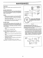
Check the crankcase oil level before starting the engine
and after each eight (8) hours of continuous use. Add SAE
30W motor oil or equalivenL Tighten oil fill cap/dipstick
securely each time you check the oil level, SAE 5W-30
motor oil may be used to make starting easier in areas
where temperature is consistently 32 ° F or lower,
TO CHANGE ENGINE OIL (See Fig 13)
(See Fig. 12)
Your unit has a battery charging system which is sufficient
for normal use, However, periodic charging of the battery
with an automotive charger will extend it's life
•
Acid solution level in each battery cell should be even
with bottoms of ventwells Add only distilled or iron free
water if necessary. Do not overfill.
Determine temperature range expected before oil change.
All oil must meet API service classification SG.
CUT AWAY VIEW
,VENT
WELL
BATTERY
CELLACID
LEVEL
FIG. 12
.
.
•
•
TO
Keep battery and terminals clean,
Keep battery bolts tight.
Keep vent caps tight and smaN vent holes in caps open.
Recharge at 6 amperes for 1 hour,
CLEAN BATTERY AND TERMINALS -
•
Be sure vehicle is on level surface.
•
•
Oil will drain more freely when warm
Catch oil in a suitable container
•
Remove oil fill dipstick, Be careful not to allow dirt to
enter the engine when changing oil,
•
Remove drain plug
°
After oil has drained completely, replace oil drain plug
and tighten securely
•
Refill engine with oil through oil fill dipstick tube. Pour
slowly, Do not overfill For approximate capacity see
Product Specifications on page 3 of this manual,
,
Use gauge on oil fill dipstick for checking level Be sure
dipstick cap is tightened securely for accurate reading,
Keep oil at "FULL" line on dipstick,
Corrosion and dirt on the battery and terminals can cause
the battery to "leak" power.
•
•
•
•
•
•
•
RECOMMENDED SAE VISCOSITY GRADES
Remove terminal guard°
Disconnect BLACK battery cable first then RED battery cable and remove battery from tractor.
Wash battery with solution of four tablespoons of
baking sodatoone gallon of watero Be carefui nottoget
the soda solution into the cells,
.20 o
Rinse the battery with plain water and dry.
Clean terminals and battery cable ends with wire brush
until bright,
Coat terminals with grease or petroleum jelly°
Reinstall battery (See "INSTALL BATTERY" in assembly section of this manual),
0o
32=
60 °
80 °
100 °
SCREEN
OIL FILL DIPSTICK
V-BELTS
Check V-belts for deterioration and wear after 100 hours
and replace if necessary. The mower blade drive belt can
be adjusted to provide you with longer belt life (See "TO
ADJUST MOWER BLADE DRIVE BELT" in Service and
Adjustments section of this manual),
DRAIN PLUG
The motions drive belt is not adjustable, Replace belts if
they begin to slip from wear.
TRANSAXLE
FIG, 13
AIR FILTER
COOLING
(See Fig. 14)
Your engine will not run properly and may be damaged by
using a dirty air filter, Remove cartridge every 25 hours and
tap gently to clean. Replace paper cartridge once a year or
after every 100 hours of operation, more often if used in
very dusty, dirty conditions
.
Remove knob and cover,
Keep transaxle free from build-up of dirt and chaff which
can restrict cooling,
ENGINE
LUBRICATION
Change the oil after the first two hours of operation and
every 25 hours thereafter or at least once a year if the
tractor is not used for 25 hours in one year,
16
,
Remove cartridge nut and clean or replace cartridge,
•
Reassemble and tighten securely
NO'[E:
Do not attempt to oil the paper cartridge
,,l=,
=
=,=,=,,,==
NTENANCE
MUFFLER
COVER
KNOB "----"-'-_-'_
=_
Inspect and replace corroded muffler and spark arrester (if
equipped) as it could create a fire hazard and/or damage.
SPARK
CARTRIDGE
PLUGS
Replace spark plugs at the beginning of each mowing
season or after every 100 hours of use, whichever comes
first. Spark plug type and gap setting is shown in "PRODUCT SPECIFICATIONS" on page 3 of this manual.
COVER
PAPER
CARTRIDGE
j_
NIJT
IN-LINE
__AtR
CLEANER
BASE
(See Fig. 13)
The engine air screen must be kept free of dirt and chaff to
prevent engine damage from overheating. Clean with a
wire brush or compressed air to remove dirt and stubborn
dried gum fibers.
ENGINE
COOLING
(See Fig. 16)
•
With engine cool, remove filter and plug fuel line
sections..
•
Place new fuel filter in position in fuel line.
•
Be sure there are no fuel line leaks and clamps are
properly positioned.
•
Immediately wipe up any spilled gasoline
FIG. 14
AIR SCREEN
FUEL FILTER
Fuel filtershould be reptaced once each season. If fuel filter
becomes clogged, obstructing fuel flow to carburetor, replacement is required.
FINS (See Fig. 15)
Remove any dust, dirt or oil from engine cooling fins to
prevent engine damage from overheating
•
Remove oil fill dipstick and cover opening to prevent
entry of dirt.
•
Remove screws from blower housing and lift housing
off engine.
•
Remove the screws securing the starter housing and
lift housing off engine.
•
Use compressed air or stiff bristle brush to thoroughly
clean engine cooling fins.
•
To reassemble, reverse above procedure.
SCREWS
BLOWER
FIG. 16
CLEANING
HOUSING
SCREWS
.
Clean engine, battery, seat, finish, etc. of all foreign
matter.
•
Keep finished surfaces and wheels free of all gasoline,
oit, etc.
•
Protect painted surfaces with automotive type wax,
We do not recommend using a garden hose to clean your
unit unless the electrical system, muffler, air filter and
carburetor are covered to keep water out Water in engine
can result in a shortened engine life
STARTER
HOUSING
OIL FILL
DIPSTICK
ENGINE COOLING
FINS
S PAR K
PLUG
FIG. 15
17
SERVmCE AND ADJUSTMENTS
i
11 m =H mini
CAUTION;
=liiN,i,
i,
1,1 ,1,,,,,,, ,,m ,=,,,,,r=
BEFORE PERFORMING ANY SERVICE OR ADJUSTMENTS:
••
.
Depress
clutch/brake
fully andposition.
set parking brake.
Place
gearshift
lever inpedal
"NEUTRAL"
Place attachment clutch in "DISENGAGED"
position.
•
•
•
Turn ignition key"OFF"
and remove key.
Make sure the blades and all moving parts have completely stopped.
Disconnect spark plug wire from spark plug and place wire where it cannot come in contact with
plug.
TRACTOR
TO INSTALL
TO REMOVE
MOWER
(See Fig. 17)
Mower will be easier to remove from the right side of unit°
•
Remove mower blade drive belt from engine pulley
only !See TO REPLACE MOWER BLADE DRIVE
BELT' through step removing belt from engine pulley).
•
Remove retainer spring from clutch rod; pull clutch rod
out of clutch lever
•
Pull retainer springs out of rear suspension trunnions.
Remove rear suspension trunnions from lift brackets
•
Pull retainer springs from front hinge pins.
•
Remove hinge pins attaching parallel link to mower
and front axle
Raise lift lever to raise suspension
out from under tractor,
arms,
CLUTCH
LEVER
•
Slide mower under tractor with discharge guard to right
side of tractor
•
Install parallel link to front axle and mower with hinge
pins Secure hinge pins with retainer springs°
Install clutch rod in clutch lever and secure with retainer
spring,
lift lever to its highest position.
•
Lower attachment lift lever to lower suspension arms.
Slide trunnions through lift bracket holes and secure
with retainer springs
.
Roll belt over engine pufley. Make sure belt isinside all
puliey grooves and inside heft guides.
Raise attachment lift lever to raise mowerr
•
Slide mower
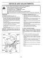
TO LEVEL
MOWER
HOUSING
Ad ust the mower while tractor is parked on Ievel ground or
dr veway.
Make sure tires are properly inflated (See
"PRODUCT SPECIFICATIONS"
on page 3). If tires are
over or under inflated, you wilt not properly adjust your
mower.
SIDE-TO-SIDE
RETAINER
SPRING
ADJUSTMENT
Raise attachment lift lever to its highest position.
•
Measure height from bottom of deck curl to ground
level at front corners of mower, Distance "A" should be
the same.
•
If distance "A" needs to be changed, snap out access
hole cover on left side of tractor above footrest.
o
SPRINGS
To raise left side of mower, loosen nut "B" and tighten
nut "C".
JPARALLEL
To lower left side of mower, loosen nut "C" and tighten
nut "B",
SUSP ENSION
_AINER
When distance "A" is equal, securely tighten nuts "B"
and "C'L
LINK
Replace access hole cover,
rRu
LIFT I
BRACKET
°NNI_
I
RETAINER
SPRING
ENGINE
PULLEY
(See Figs.18 and19) -
•
CLUTCH
ROD
RM
(See Fig. 17)
Raise attachment
•
IMPORTANT:
IF AN ATTACHMENT
OTHER THAN THE
MOWER IS TO BE MOUNTED TO THE TRACTOR,
THE
R.H.AND L,H. SUSPENSION
ARMS MUST BE REMOVED
FROM TRACTOR,
CLUTCH
ROD
MOWER
•
HINGE
PINS
FIG. t7
t8
SERVICE AND ADJUSTMENTS
REAR SUSPENSION
LIFt*LEVER
(RAISED
POSITION)
ARM
\
_'--_
BOTTOM
OF CURL
BOTTOM
OFCURL
BOTTOM
OFCURL
|ROUND _ D
REAR SUSPENSION
TRUNNION
LINE
FIG. 20
\
A
GROUND LINE
REAR
SUSPENSION
REAR
SUSPENSION
ARM
FIG. 18
TRUNNIO_uT
.F_,
_
SIDE TO SIDE
ADJUSTMENT
TRUNNION
"_
NUT "C"
-
_'
_
/_NUT"B"
LIFT BRACKET
FIG. 21
FtGo 19
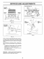
FRONT-TO-BACK ADJUSTMENT(See Figs. 20 and 21)
To obtain the best cutting results, the mower housing
should be adjusted so the rear is approximately 3/4 to 7/8"
higher than the front when the mower is in its highest
position
Check adjustment on right side of tractor° Measure distance "D" at front and rear flanges of mower housing as
shown.
To raise rear of mower, loosen nut "E" on both rear
suspension arms. Screw both nuts "F" on both rear
suspension arms an equal number of turns.
,i
When distance "D" is 3/4 to 7/8" higher at rear than
front, retighten nuts "E".
Recheck side-to-side adiustmenL
IMPORTANT:
WHEN ADJUSTING
REAR SUSPENSION
TRUNNIONS,
ALWAYS ADJUST
BOTH
EQUALLY
SO
MOWER
WILL STAY LEVEL SIDE-TO-SIDE
19
iii i1,,11ii ii1,, i,
ill ,lll,,lll
.........................
SERVNCE AND ADJUSTMENTS
i
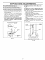
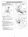
TO ADJUST
MOWER
(See Fig. 22)
BLADE
DRIVE
BELT
IDLER BELT
GUIDE
Your tractor has been manufactured with the ability to
readjust the mower blade drive belt to provide you with
longer belt life,
With the engine off and the lift lever in the highest position, move clutch lever up slowly until resistance is felt,
If distance from bottom of slot in dash to clutch lever is
greater than 4-1/2 inches, adjustment is necessary
,
Lower the mower deck for easier access,
•
Remove the bolt, nut
rock shaft assembly,
o
Move extension spring from lower to upper end of
slot in rock shaft assembly and install bolt, nut and
the D-shaped washers (flat side of washers down).
•
Tighten bolt and nut to secure the D-shaped washers (flat side down as shown).
TO
REPLACE
(See
Figs.
BELT
ENGINE PULLEY
L,H,
MANDREL
\
IDLER
EXTENSION
SPRING
and D-shaped washers from
MOWER
22 and
i
BLADE
DRIVE
R_H.
MANDREL
ROCKSHAFT
EMBLY
BELT
23)
The mower blade drive belt may be replaced without
tools Park the tractor on level surface Engage parking
brake, For assistance, there is a belt installation guide
decal on the mower housing,
SPRING
BRAKE
ROD
BELT REMOVAL •
•
Place attachment clutch in "DISENGAGED" position,
Move attachment lift lever forward to lower mower to
its lowest position,
•
Roll belt off engine pulley,
•
Pull belt off both mandrel pulleys
•
Spring belt guide away from idler pulley and pull belt
off idler pulley
•
Slide belt from under extension spring,
BELT INSTALLATION
NUT
FIG, 22
-
•
Slide belt under extension
•
Place belt around back side and in groove of both
mandrel pulleys,
•
Spring idler belt guide down and place belt around
rear side of idler pulley
.
Roll belt over engine pulley
•
Make sure belt is in all pulley grooves and inside all
belt guides.
BELT
GUIDES
spring.
FIG, 23
2O
ENGINE
PULLEY
i
i
inH,==
==l
,,,i,
m,,,i,,H..........
SERVICEAND
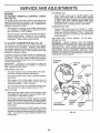
TO ADJUST
BRAKE
,,H,,,,,
ADJ
Your unit is equipped with an adjustable brake system
which is mounted on the right side of the transaxle.
Depress clutch/brake pedal and engage parking brake.
•
Measure distance between brake operating arm and
nut "A" on brake rod,
•
If distance is other than 1-1/2", disengage parking
brake, loosen jam nut and turn nut "A" until distance
becomes 1-1/2". Retighten jam nut against nut "A",
•
Engage parking brake and recheck distance.
•
Road test unit for proper stopping distance as stated
above. Readjust if necessary, If stopping distance is
still greater than six (6) feet in highest gear, further
maintenance is necessary,
Contact
your nearest
Sears Service Center.
WITH PARKING
MOTION
DRIVE BELT (See
The tractor drive belt may be replaced without toots.
Park the tractor on level area
Engage parking brake
For assistance, there is a heft installation guide decal on
bottom side of left footrest.
•
Remove mower (See "TO REMOVE MOWER" in this
section of this manual).
•
Roll belt over top of transaxle pulley.
•
Rotl belt over engine puiiey and off idler.
•
Release parking brake Pull belt as far as possible
over top of clutch puIley
•
Reset parking brake.
Pull belt over top of clutch
pulley
•
PutI belt out up through gearshift lever gate opening
to remove from tractor
•
install new belt by reversing above procedure.
IMPORTANT:
REPLACE ONLY WITH BELT LISTED
1N THIS MANUAL.
if unit requires more than six (6) feet stopping distance at
high speed in highest gear, then brake must be adjusted
.
STMENTS
TO REPLACE
Fig. 25)
(See Fig. 24)
x x
BRAKE "ENGAGED"
ENGINE
PULLEY
CLUTCH
IDLER
JAM NUT
OPERATING
ARM
FIG. 24
VIEWED
FROM BOTTOM OF TRACTOR
FtG_ 25
21
illlll
i
ill
i,iiiP
$ERVHCE AN
i
TO ADJUST
STEERING
i
ii ,i,,ll
WHEEL
i
,
i, iil,
ADJUSTMENTS
H,IH,
TO START ENGINE WITH A WEAK BATTERY
(See Figs. 27 & 28)
ALIGNMENT
If steering wheel crossbars are not horizontal (left to right)
when wheels are positioned straight forward, remove
steering wheel and reassemble per instructions in the
Assembly section of this manual,
FRONT
WHEEL
CAUTION: Lead-acid batteries generate explosive gases. Keep sparks, flame
and smoking materials away from batteries.
Always wear eye protection
when around batteries.
TOE-IN/CAMBER
The front wheel toe-in and camber are not adjustable on
your unit° If damage has occured to affect the frorit wheel
toe-in or camber, contact your nearest Sears Service
Center,
TO REMOVE
Fig, 26)
i i!
WHEEL
FOR REPAIRS
If your battery is too weak to start the engine, it should be
recharged° If "jumper cables" are used for emergency
starting, follow this procedure:
IMPORTANT:
YOUR UNIT tS EQUIPPED WITH A 12
VOLT NEGATIVE GROUNDED SYSTEM, THE OTHER
VEHICLE MUST ALSO BE A 12 VOLT NEGATIVE
GROUNDED SYSTEM. DO NOT USE YOUR TRACTOR
BATTERY TO START OTHER VEHICLES.
TO ATTACH JUMPER CABLES •
Connect each end of the RED cable to the POSITIVE
(+) terminal of each battery, taking care not to short
against chassis
.
Connect one end of the BLACK cable to the NEGATIVE (_) terminal of fully charged battery.
(See
•
Block up axle securely.
•
Remove hub cap, retaining ring and washers to allow
whee] removal (rear wheel contains a square key - Do
not lose).
•
Repair tire and reassemble,
•
On rear wheels only: align grooves in rear wheeE hub
and axteo Insert square key.
•
Replace washers and snap retaining ring securely in
axle groove.
•
Reptace hub cap,
•
Connect the other end of the BLACK cable to a panel
bolt on the left side of the chassis, away from fuel tank
and battery.
TO REMOVE CABLES, REVERSE ORDER,
•
BLACK cable first from left side of chassis and fully
charged battery_
RED cable last from both batteries.
WASHERS
RETAINING
RING
"POSITIVE"
"NEGATIVE"
(*)
(-)
FIG. 27
HUBCAP
(REAR WHEEL ONLY)
PANEL
FIG. 26
_"%,
BOLT
FIG_ 28
22
_//_
_
SERVICE AND ADJUSTMENTS
u ,,11,n
TO REPLACE
FUSE (See Fig. 29)
LIGHT
CONNECTOR
HOOD
Replace with 30 amp automotive4ype plug-in fuse, The
fuse holder is located in the engine compartment, directly
in front of the dash,
HOOD SPRING
FUSE
HOLDER
HINGE BRACKET
FIG. 29
TO REPLACE
HEADLIGHT
FIG_ 30
BULB
•
Raise hood.
•
Pull bulb holder out of the hole in the backside of the
grill
Replace bulb in holder and push bulb holder securely
back into the hole in the backside of the gal!!,
•
•
HOOD PIVOT ROD
HINGE BRACKET
Close hood.
INTERLOCKS
AND
RELAYS
Loose or damaged wiring may cause your tractor to run
poorly, stop running or prevent it from starting
•
Check wiring. See electrical wiring diagram in Repair
Parts section of this manual.
TO REMOVE HOOD, GRILL
ELS (See Fig's, 30 and 31)
•
AND SIDE PAN-
Raise hOOdr
•
Unsnap headlight wire connector.
,
Stand at side of tractor. Grasp hood and tilt forward
and lift off hinge brackets.
•
SLOT
FIG. 31
To reinstall,slide hood pivot rod into slot in hinge
brackets, and carefully reinstall hood springs.
23
GOVERNED
ENGINE
TO ADJUST THROTTLE
(See Fig. 32)
CONTROL
.
CABLE
IDLE -
Move throttle control lever to "SLOW" position+ With
finger hold throttle shaft in closed position against
throttle stop (counterclockwise) Turn idle speed screw
to attain 1550 RPM. Release throttle shaft, Move
throttle control lever to attain t 750 RPM+Turn governor
idle screw until it contacts governor control lever.
The throttle control has been preset at the factory and
adjustment should not be necessary+ Checkadjustment as
described below before loosening cable+ If adjustment is
necessary, proceed as follows:
ACCELERATION
•
With ,engine,,no!, runningl, move throttle control lever
from ,SLOW !o CHOKE position. SIowlymove lever
from CHOKE to FAST position+
•
•
Check that hole in governor control lever and hole in
governor plate fine-up, If holes "A" are not aligned,
loosen clampscrew and move throttle cable until holes
are aligned Tighten clamp screw securely,
TO ADJUST
CARBURETOR
High speed stop is factory adjusted.
Do not adjust damage may result.
IMPORTANT:
NEVER TAMPER WITH THE ENGINE
GOVERNOR, WHICH IS FACTORY SET FOR PROPER
ENGINE SPEED. OVERSPEEDtNG THE ENGINE ABOVE
THE FACTORY
HIGH SPEED SETTING
CAN BE
DANGEROUS. IFYOU THINKTHE ENGINE-GOVERNED
HIGH SPEED NEEDS ADJUSTING, CONTACT YOUR
NEARESTAUTHORIZED SERVICE CENTER, WHICH HAS
PROPER EQUIPMENTAND EXPERIENCE TO MAKE ANY
NECESSARY ADJUSTMENTS,,
(See Fig. 32)
The carburetor has been preset at the factory and adjustment should not be necessary
However, minor adjustment may be required to compensate for differences in fuel,
temperature, altitude or load. If the carburetor does need
adjustment, proceed as follows:
In general turning the mixture screws in (clockwise) decreases the supply of fuel to the engine giving a eaner fue /
air mixture+ Turning the mixture screws out (counterclockwise) increases the supply of fuel to the engine giving
a richer fuel/air mixture.
IMPORTANT;
DAMAGE TO THE NEEDLES AND THE
SEATS IN CARBURETOR MAY RESULT IF SCREWS
ARE TURNED IN TOO TIGHT,
PRELIMINARY
TEST +
Move throttle control lever from "SLOW" to "FAST"
position_ tf engine hesitates or dies, turn idle mixture
screw out (counterclockwise) 1/8 turn. Repeat test
and continue to adjust, if necessary, until engine accelerates smoothly.
IDLE SPEED
SCREW
"\
THROTTLE
SHAFT
IDLE MIXTURE
SCREW
SETTING +
•
Air cteaner assembly must be assembled to the carbu+
retor when making carburetor adjustments.
.
Be sure the throttle control cable is adjusted properly
(see above)
•
With engine off turn high speed mixture screw in
(clockwise) closing it finger tight and then turn out
(counterclockwise) 1+1/4 to t-1/2 turns.
THROI_LE
CABLE
•
Turn idle mixture screw in (clockwise) closing finger
tight and then turn out (counterclockwise) 1 turn
FINAL SETTING •
Start engine and allow to warm for five minutes, Make
final adjustmen!s with engine running and shift!motion
control lever in NEUTRAL position.
•
With throttle controt lever in "FAST" position, turn high
speed mixture screw in (clockwise) until engine begins
to die then turn out (counterclockwise) untit engine runs
rough_ Turn screw to a point midway between those
two positions.
•
GOVERNOR
HIGH SPEED
MIXTURE SCREW
With throttle controt lever in "SLOW" position, turn idle
mixture screw in (clockwise) until engine begins to die
and then turn out (counterclockwise) until engine runs
rough. Turn screw to a point midway between those
two positions
CONTROL
LEVER
FIG. 32
24
HOLES "A"
GOVERNOR
CONTROL
PLATE
,
,
i iH
nunH,,,i
STORAGE
i
mm n ,H,,m,,i
Immediately prepare your tractor for storage at the end of
the season or if the unit will not be used for 30 days or more.
CAUTION: Never store the tractor with
gasoline In the tank Inside a building
where fumes may reach an open flame
or spark, Allow the engine to cool before storing in any enclosure,
Clean entire tractor (See "CLEANING"
nance section of this manual).
•
Inspect and replace belts, if necessary (See belt replacement instructions in the Service and Adjustments
section of this manuat).
Lubricate as shown in the Maintenance section of this
manual.
,
•
•
•
Start the engine and let it run until the fuel lines and
carburetor are empty,
•
Never use engine or carburetor cleaner products in the
fuel tank or permanent damage may occur.
Use fresh fuel next season.
NOTE: Fuel stabilizer is an acceptable alternative in minimizing the formation of fuel gum deposits during storage.
Add stabilizer to gasoline in fuel tank or storage container.
Always follow the mix ratio found on stabilizer container_
Run engine at least 10 minutes after adding stabilizer to
allow the stabilizer to reach the carburetor. Do not drain the
gas tank and carburetor if using fuel stabilizer,
When
it thorblades
or rust
•
Drain the fuel tank.
•
TRACTOR
Remove mower from tractor for winter storage,
mower is to be stored for a period of time, clean
oughly, remove all dirt, grease, leaves, etc, Give
and underside of housing a good coat of grease
preventative. Store in a clean, dry area,
•
ENGINE OIL
Drain oil (with engine warm) and replace with clean engine
oil (See "ENGINE" in the Maintenance section of this
manual),
in the Mainte-
CYLINDERS
Be sure that alt nuts, bolts and screws are securely
fastened_ Inspect moving parts for damage, breakage
and wear, Replace if necessary,
Touch up all rusted or chipped paint surfaces; sand
lightly before painting.
•
Remove spark plug(s).
•
Pour one ounce of oil through spark plug hole(s) into
cylinder,
•
Turn ignition key to "START" position for a few seconds
to distribute oil.
•
Replace with new spark plug(s).
OTHER
BATTERY
•
Do not store gasoline from one season to another.
•
Fully charge the battery for storage.
•
•
After a period of time in storage, battery may require
recharging.
Replace your gasoline can if your can starts to rusL
Rust and/or dirt in your gasoline will cause problems.
•
•
To help prevent corrosion and power leakage during
long periods of storage, battery cables should be
disconnected and battery cleaned thoroughly (see "TO
CLEAN BATTERY AND TERMINALS" in the Maintenance section of this manual),
If possible, store your unit indoors and cover it to give
protection from dust and dirt,
•
After cleaning, leave cables disconnected and place
cables where they cannot come in contact with battery
terminals,
.
Be sure battery drain tube is securely attached to drain
in battery tray.
,
Cover your unit with a suitable protective cover that
does not retain moisture. Do not use plastic. Plastic
cannot breathe which allows condensation to form and
will cause your unit to rust°
IMPORTANT:
NEVER COVER
TRACTOR
WHILE
ENGINE AND EXHAUST AREAS ARE STILL WARM
ENGINE
FUEL SYSTEM
IMPORTANT:
IT IS IMPORTANT TO PREVENT GUM
DEPOSITS FROM FORMING IN ESSENTIAL
FUEL
SYSTEM PARTS SUCH AS CARBURETOR, FUEL FILTER,
FUEL HOSE, OR TANK DURING STORAGE- ALSO,
EXPERI ENCE INDICATES THAT ALCOHOL BLENDED
FUELS (CALLED GASOHOL OR USING ETHANOL OR
METHANOL) CAN ATTRACT MOISTURE WHICH LEADS
TO SEPARATION AND FORMATION OF ACIDS DURING
STORAGE ACIDIC GAS CAN DAMAGE THE FUEL
SYSTEM OF AN ENGINE WHILE IN STORAGE,
25
TROUBLESHOOTING
,
PROBLEM
Will not start
i i,,i
i
POmNTS
i ii , HI,,II_,II,,I,,
CAUSE
CORRECTION
1
Out of fuel.
2
3.
4
5
6,
7
Engine not "CHOKED"
Engine flooded
Bad spark plug
Dirty air filter.
Dirty fuel filter
Water in fuel
properly.
1.
Fill fueltank.
2.
3
See TO START ENGINE in operation section.
Walt several minutes before attempting to start.
4.
5.
6
7.
Replace spark plug
Clean!replace air filter
Reptacefuet filter.
Drain fuel tank and carburetor, refill tank with fresh
gasoline and replace fuel filter.
Check all wiring.
Contact Sears Service Department.
Contact Sears Service Department.
8.
9
10
Loose or damaged wiring.
Carburetor out of adjustment.
Engine valves out of adjustment.
8,
9.
10.
Herd to start
1.
2.
3
4
5.
6.
7.
8.
Dirty air filter.
Bad spark plug.
Weak or dead battery.
Dirty fuel filter_
Stale or dirty fue{
Loose or damaged wiring.
Carburetor out of adjustment.
Engine valves out of adjustment.
t.
2.
3
4.
5
6.
7
8.
Engine will not turn over
1
2
3.
4.
5.
Clutch/brake pedal not depressed
Attachment clutch is engaged.
Spark plug wire is disconnected.
Weak or dead battery
Blown fuse
6.
7
8_
9
10
Engine clicks but will not
start
Corroded battery termina{s.
Loose or damaged wir{ng.
Faulty ignition switch
Faulty solenoidor starter.
Faulty operator presence switch(es).
12.
3.
Weak or dead battery.
Corroded battery terminals.
Loose or damaged wiring.
4.
Faulty solenoid or starter.
Ctean/repface air filter
Replace spark p_ug_
Recharge or replace battery.
Replace fuel filter.
Drain fuel tank and refill with fresh gasolineo
Check all wiring.
Contact Sears Service Department.
Contact Sears Service Department.
I.
2.
3.
4.
5.
6.
7.
8
9.
10_
Depress Clutch/brake pedal.
Disengage attachment clutch
Connect wireto spark plug.
Recharge or replace battery.
Replace fuse.
Clean battery terminals.
Check all wiring.
Check/replace ignition switch.
Check/replace solenoid or starter
Contact Sears Service Department.
1.
2.
3
4.
Recharge or replace battery.
Clean battery terminals.
Check all wiring.
Chectdreplace solenoid or sterter_
im=,J=,l
Loss of power
1.
2.
3.
4.
5
6
7.
8.
9.
t0.
t I
12_
I3t4
! 5.
Excessive vibration
Cutting too much grass/too fast.
Throttle in "CHOKE" position.
Build-up of grass, leaves and trash under mower_
Dirty air lifter.
Low ell feveVdirty oil
Fautty spark p{ug
Dirty fuel filter.
Stale or dirty fuel
Waterin fuel.
Spark piug wire loose.
Dirty engine air screen/fins.
Dirty/clogged muffler.
Loose or damaged wiring°
Carburetor out of adjustment.
Engine valves out of adjustment.
1.
2-
Worn, bent or loose btade.
Bent blade mandrel
3
Loose/damaged
1.
2.
3.
4
5.
6
7.
8.
9.
10.
11.
12.
13.
14.
15.
1.
2.
3-
part(s).
26
Set in "Higher Cut" position/reduce speed.
Adjust throttle control.
Clean underside of mower housing.
Clean/replace air filter.
Check oil level/change oil.
Clean and regap or change spark plug.
Replace fuel filter.
Drain fuel tank and retiII with fresh gasotineo
Drain fuel tank and carburetor, refill tank with fresh
gasoline and replace fuel filter.
Connect and tighten spark plug wire.
Clean engine air screen/fins.
Clean/replace muffier_
Check all wiring_
Contact Sears Service Department.
Contact Sears Service Department.
Replace blade. Tighten blade bolt.
Replace blade mandrel.
Tighten loose part(s) Replace damaged parts.
i
.....................................................................
i
TROUBLESHOOTING
POINTS
......................
PROBLEM
i ii
CAUSE
nu ii mnul ,ml
CORRECTION
presence control system,
1- Check wiring,switches and connections,if not
corrected,contactSears Service Department,
1_
Fau_y oper_o_safe_
Poorcut-uneven
1,
2.
3.
4.
Worn, bent or toose blade,
Mower deck not level
Build-up of grass, leaves, and trash under mower,
Bent blade mandrel
1.
2
3,
4.
Mower blades wltl not
rotate
1.
Obstruction
1,
Remove obstruction.
2.
3
4,
5
Mower drive belt out of adjustmentWorn/damaged mower drive belt,
Frozen idler pulley.
Frozen blade mandrel.
2,
3,
45,
Adjust mower drive belt.
Replace mower drive belt
Replace idler pulley.
Replace blade mandrel.
1.
2.
34.
Engine speedtoo slow.
Travel speed too fast.
Wet grass.
Mower deck not level.
1
2.
3
4,
Place throttle control in "FAST" position,
Sh{ft to slower speed.
Allow grass to dry before mowing_
Level mower deck.
Low/uneven tire air pressure,
Worn, bent or loose blade,
Build-up of grass, leaves and trash under mower.
Mower drive belt worn or out of adjustment
Blades improperly installed.
Improper bladesused
5
6.
7,
&
9,
Check tires for proper air pressure,.
Replace/sharpen blade. Tighten blade bolt
Clean underside of mower housing
Replace/adjust mower drive belt.
Reinstall blades sharp edge down.
Engine continues to run
when operator leaves seat
with attachment clutch
engaged
Poor grass discharge
5
67
8.
9.
10.
in clutch mechanism.
i0,
Replace blade, Tighten blade bolt.
Level mower deck.
Clean underside of mower housfng
Replace blade mandrel.
Replace with blades listed in this manual.
Headlight(s) not working
(if So equipped)
1.
Switch is "OFF".
2.
3.
4.
5,
Bulb(s) burnedout.
Faulty light switch,
Loose or damaged wiringBlown fuse.
I,
2.
3
4
5,
Turn switch "ON"
Replace bulb(s)
Check/replace light switch.
Check wiring and connections,
Replace fuse.
Battery will not charge
1.
2.
Bad batterycell(s).
Poor cabte connections.
1o
2.
Replace battery
Check/clean alf connections,
3
4
Faulty regulator (if so equipped).
Faulty alternator.
3,
4,
Replace regulator.
Replace a{ternator
27
i
SERVICE
28
NOTES
REPAIR PARTS
12.0 HP 38" RIDING
LAWN TRACTOR
-- MODEL
NUMBER
917.254530
SCHEMATIC
BATTERY
I
I
I
RED
RED
.Eo )
FUSE 30 AMP
STARTER
WHITE
SOLENOID
BLACK
IGNITION SWITCH
f
I
I
I
I
I
I
I
I
I
j
I
t
I
i
_,
BLACK
7
.........
(PEDAL UP)
CLUTCH/BRAKE
l___
i
BLACK I ATT'MENT CLUTCH
(CLUTCH OFF)
t
f"_
f'-'\
_ Lt BLACK &
SEAT
SWITCH
(NOT OCCUPIED)
@
@
GNTo.
F SPARK
8LACK
UNIT
PLUG
RED
ALTERNATOR
20 VOLTS
@ 3600 RPM
(BATTERY _N LINE)
NOTE
IGNITION SWITCH
POSITION
CIRCUIT
..................
OFF
ON
START
--0--
', =,;I
M+G
B+L
B+S
NON-REMOVABLE
CONNECTIONS
ORANGE
YOUR TRACTOR iS EQUIPPED
WITH A SPECIAL ALTERNATOR
SYSTEM. THE LIGHTS ARE NOT
CONNECTED TO THE BATTERY,
BUT HAVE THEIR OWN
ELECTRICAL SOURCE.
BECAUSE OF THIS, THE BRIGHTNESS OF THE LIGHTS WILL
CHANGE WITH ENGINE SPEED.
AT IDLE THE LIGHTS WILL DIM,
AS THE ENGINE IS SPEEDED UP,
THE LIGHTS WILL BECOME
THEIR BRIGHTEST,
_
REMOVABLE
CONNECTIONS
29
[
I
AC (M{N)
_
__
_-_t'--,,5AMP
s
ALTERNATOR
@ 11VOLTS AC @ 3600 RPM
WIRING INSULATED
CLIPS
NOTE: If wiring insulated clips were removed for servicing
of unit, they should
be replaced to properly secure your wiring.
REPAIR PARTS
12 HP 38" RIDING
LAWN TRACTOR
- - MODEL
NUMBER
917,254530
ELECTRICAL
10
/
\
\
\
18 _
.....32
\
24
8
I
I
33
J
30
REPAIR PARTS
12 HP 38" RIDING
LAWN TRACTOR
-- MODEL
NUMBER
917.254530
ELECTRICAL
KEY
NO,
1
2
3
4
5
6
7
8
9
10
11
12
13
14
15
16
17
18
19
20
21
22
PART
NO.
7662J
127441X
124904X
109310X
110712X
104445X
7603J
109596X
STD365402
108824X
STD551125
73350400
74780408
STD541425'
4799J
11050400
719J
5114J
109553X
4207J
74760412
STD551025
DESCRIPTION
KEY
NO.
Bulb, Light
Harness, Li.ght Socket
Harness, W_ring
Key, Motded
Switch, Light
Switch, Interlock
Tray, Battery
Clamp, Hose
*Switch, Ignition
Fuse
*Washer, Lock, 1/4
Nut, Hex Jam 1/4-20
Bolt, Hex, 1/4-20 x 1/2 Gr. 5
*Nut, Keps 1/4-20
Cable Assembly
Washer, Lock, Ext. Tooth 1/4
Cover, Terminal
Cable, Battery
Switch, Interlock
Cable, Battery
Bolt, Hex 1/4-20 x3/4
*Washer9i32x5/Sx16Ga.
A
23
24
25
26
27
28
29
30
31
32
33
34
35
36
STD541025
t21265X
102476X
123198X
STD551125
72240460
109081X
109787X
t09788X
7192J
105687X
121305X
STD601005
74641008
37
38
39
---
73951000
4171R
121264X
10t539X
128305
DESCRIPTION
* Nut, Hex 1/4-20
Battery
Terminal Guard
WingNut
1/4-20
*Washer, Lock Hvy Helical Spring
Bolt, Carriage 1/4-20 x 7-1/2
Solenoid
Bezel, Ignition
Nut, Ignition
Cable Tie
Tube, Plastic
Switch, Plunger
*Screw, Tap Hex Hd. #10 x 24 UNC
Screw, Slotted Pan Hal.
# t0-32 x 1/2
Nut, Keps # 10-32 x 1/2
Clip, Insulated
Battery Caps Set
Sheet, Instruction, Tractor, 15 °
Manual, Owner's
* STANDARD HARDWARE
B
12
PART
NOo
C
13
D
36
16®37
31
35
- PURCHASE LOCALLY
Q
IL!
m
7.J
W
\
0
|
|
0
I.-
z
w
nG_
0
z
m
a
Z
_n
I/1
C}
32
J
,<
0
e_
I..0
0
0
9
ILl
CO
o
LU
tr
e_
rr
,_
m
Z
W
0
b
R
0
Z
t-
0
m
0
m
m
W
Iw
z
u'/
W
o
33
cD
REPAIR PARTS
12 HP 38" RIDING
LAWN
TRACTOR
MODEL
NO. 917.254530
DRIVE
(_/93
9
69
/
96
95
55
57
_
67
88
t
OPTIONAL
Spark
34
EQUIPMENT
Arrester
30
REPAIR PARTS
12 HP 38" RIDING
LAWN
TRACTOR
MODEL
NO. 9'17.254530
DRIVE
KEY
NO.
1
PART
NO.
124136X
2
4
5
6
7
8
9
10
11
12
t3
14
131002
STD551143
71130720
125907X
125610X
125593X
101326L
71070510
STD55113t
121218X
73220500
17490620
15
16
STD551125
120897X
2O
21
22
23
24
123666X
12000028
109167X
STD5237!0
17490512
26
3O
32
33
34
35
36
37
38
39
40
4t
42
127275X
STD541437
t27274X
STD523707
12t748X
106933X
124461X
71040412
10570IX
STD561210
19151216
104777X
17490612
43
44
45
46
47
48
49
5O
51
52
53
19131312
105730X
!09070X
4470J
123674X
127783
123789X
STD523715
105709X
110812X
12000039
KEY
NO.
DESCRIPTION
Engine, 12 HP, Briggs and Stratton,
Model No. 281707, Type No, 0412-01
Pulley Engine
*Washer, Lock, HW Helical Spring
Bolt, Hex 7/16_20 x 1-1/4 Grade 8
54
55
57
58
59
V-Belt,
5-_
Muffler Drive t/_._'_C._L_
Gasket
/_ ,1, _'[_
Deflector, Muffler
Hex Hd. Cap Screw 5/16-18 x 5/8
* Washer, Lock 5/16
Keeper, Belt, Engine
Nut, Hex 5/16x 18
Screw, Hex Washer Thd. Roiling
3/8 x 16 x 1-1/4
* Washer, Lock, HW. Helical Spring
Transaxle, Foote-Dana, 5 Speed,
Mode! No. 4360-6
Pulley, Transaxfe
Ring, Retainer
Bracket Transaxle
* Bolt, Hex 3/8-16 x 1
Screw, Hex Washer Thread Rolling
5/16-18 x 3/4
Keeper, Be!t, L.H.
* Nut, Crownlock 318-16
Keeper, Be!t, R.H
* Bolt, Hex 3/8-16 x 3/4
Washer 25/32 x 1-5/8 x 16 Ga.
Knob, Shift
Rod, Shift
Bolt, Hex 1/4-28 x 3/4
Washer, Shift Plate
* Pin,Cotter I/8 x 1
Washer t5/32 x 3/4 x 16 Ga.
Retainer, Belt
Screw, Hex Washer Thd. Roiling
318 16 x 3/4
Washer I3/32 x t3/16 x 12 Ga
Keeper, Belt, Engine
Retainer, Belt
Spacer
Idler, Flat
Idler, V. Grove
Arm, Idler (Includes Key #80)
*Bolt, Hex 3/8-16x 1-1/2
Spring, Return, Clutch
Washer, Hardened
Ring, Klip
6I
60
A
B
D
E
F
62
63
64
65
66
67
68
69
70
71
72
73
74
75
76
77
79
80
81
82
83
84
85
86
87
88
89
90
91
92
93
94
95
96
PART
NO.
Link, Clutch
* Pin, Cotter 1/8 x 3/4
Rod, Brake
Spring, Rod, Brake
Nut, Jam 3/8-16
Washer 13/32 x 13/36 x 16 Ga.
125638X
19131316
Rod, Brake, Parking
Cap, Plunger
124236X
Shaft, Foot Pedal
122424X
Cover - Pedal
8883R
Washer 25/32 x 1..1/4 x t6 G&
t21749X
*Pin, Ro!!, 3/16 x 1
STD571810
Bearing, Nylon
120183X
Key, Square 2.5 x. 1845/_ 1865
123583X
Nipple, Pipe 3/8 NPT 3"
I328032X
Cap, Valve
59192
Stem, Valve
65139
Tire, Rear
123969X
Rim Assembly, Rear
106108X361
Spacer
I09502X
Locknut, Hex, W/Washer Insert
73800600
3/8-16
E-Ring
12000001
Strap, Torque, TransAxle
121520X
Spring - Brake
110422X
Bearing
105706X
Retainer - Belt
123205X
Screw
- Spider Lock #8-18 x 1/2
17030808
ABTPS
Spring
105700X
Plate, Shift
106919X
Washer 9/32 x 3/4 x 10 Ga°
19091210
Washer, Lock, Ext. Tooth 3/8
11050600
Tube, Tire (not furnished with tractor)
7152J
Spark Arrester
121851X
STD551062 *Washer 21/32 x 1 x t6 Ga.
STD523727 * Bolt, Hex 3/8 x 16 x 2-3/4
Cap, Axle
104757X
* Washer 9/32 x 5/8 x 16 Ga.
STD551025
Clip, Fue! Line
2751R
* Bolt, Hex Fin 1/4 x 20 UNC x 1
STD522510
Oil Drain Plug (order from
manufacturer)
Elbow
13200300
Decal, HP, Engine
126685X
105710X
STD561210
110437X
106888X
73350600
NOTE:
G
DESCRIPTION
*STANDARD HARDWARE- -PURCHASE LOCALLY
All component dimensions given in UrS. inches,
1 inch = 25.4 ram
H
K
L
M
P
N
@15
(_43
30
--30 @ 11
35
86
92
REPAIR PARTS
12 HP 38" RIDING
LAWN TRACTOR
- - MODEL
NUMBER
917,254530
STEERING ASSEMBLY
30
28
25
42
t5
1
i
56 55
59
36
27
30
REPAIR
PARTS
12 HP 38" RIDING
LAWN TRACTOR
- - MODEL
NUMBER
917.254530
STEERING ASSEMBLY
KEY
NO,
1
2
3
4
5
6
PART
NO,
123042X
74180512
73510500
! 09816X
124434X
STD522510
7
8
9
10
126684X
124417X
124465X
17490608
11
13
14
15
16
17
18
19
22
275IR
100710L
STD541350
100712K
100713N
100711L
STD551125
71070410
STD611005
24
25
26
124373X
124036X
17490612
27
28
29
30
31
32
34
35
6266H
124034X
124035X
12000029
57079
128752
104757X
5479J
DESCRIPTION
KEY
NO.
Dash
Screw, Truss Hd, 5/16-18 x 3/4
Nut, Keps 5/16-18
Nyliner, Snap In
Control, Throttle
* Screw, Hex Thread Cut
1/4 x 20 x 5/8
Washer 5/8 x 1/4 x t6 Gao
Boot, Steering Shaft
Saddle
Screw, Hex Washer Hd Thread
Rolling 3/8-16 x 1/2
Clip, Insulated
Insert, Steering Wheel
* Locknut, Hex Jam 1/2-20
Washer 2-1/4
Wheel, Steering
Adapter, Steering Wheel
*Washer, Lock 1/4
Screw, Socket Hex 1/4 - 20 x 5/8
* Screw, Hex Self Tap #10-16 x 1/2
Type ABTPS
Bushing, Steering
Bracket, Steering
Screw, Hex Washer Thread Rolling
3/8-16 x 3/4 Type TT
Bearing, Thrust
Gear, Sector
Shaft, Support
Klip Ring
Washer, Hardened
Shaft, Steering
Cap, Axle
Plug, Button
A
B
PART
NO.
36
39
40
41
42
43
45
46
47
48
49
50
51
52
53
54
55
56
57
58
59
60
61
63
124033X
74761060
I05669X
1t0438X
73601000
19212010
3366R
105715X
120754X
19131416
76020412
STD551137
73610600
128122
105656X
130524
278H
9040H
106732X361
59192
65139
124157X
121749X
59904
64
65
67
68
---
121748X
STD55123t
192720I6
121232X
125879X
108456X
* STANDARD
D
®3
F
H
@65
®3
37
DESCRIPTION
Shaft, Pitman
Bolt, Hex 5/8-11 x 3-3/4
Axle, Front
Spacer, Bearing, Front Axle
Locknut, Flange 5/8-16
Washer 21/32 x 1-1/4 x 10 G&
Bearing
Rod, Tie
Bushing
Washer 13/3l x 7/8 x 16 Ga,
Pin, Cotter 1t8 x3/4
* Washer, Lock 3/8
Nut, Fin Hex 3/8 - 24 UNF
Link, Drag
Spindle, L,H,
Spindle, RoHo
Fitting, Grease
Bearing, Flange
Rim, Front (lnc_ 2 each key no 56)
Cap, Valve
Stem, Valve
Tire, Front
Washer 25/32 x 1-1/4 x 16 Ga,
Tube, front (not furnished with
tractor)
Washer 25/32 x 1-5/8 x 16 Ga,
*Washer, Lock, Int. Tooth 5/16
Washer 27/32 x 1-1/4 x 16 Ga.
Cap, Spindle
Decal, Steering Wheel Cap
Decal, Instruction, Operating
HARDWARE - PURCHASE LOCALLY
REPAIR PARTS
12 HP 38" RIDING
LAWN TRACTOR
- - MODEL
NUMBER
917.254530
LIFT ADJUSTMENT
19
45,,,_
D_t
3B
REPAIR PARTS
12 HP 38" RIDING
LAWN TRACTOR
- - MODEL
NUMBER
917.254530
LIFT ADJUSTMENT
KEY
NO,
PART
NO,
I
2
3
4
5
6
7
8
9
I0
1I
12
13
14
124429X
106932X
106451X
73680600
106452X
19171516
17021008
106447X
123549X
109202X
101335K
124028X
123487X
17490608
15
16
17
18
19
20
2!
22
23
19091416
122795X
121794X
124031X
19211416
STD581062
122365X
122512X
17490412
24
25
26
27
28
29
30
105736X
5320R
120183X
105839X
105838X
STD551025
122507X
DESCRIPTION
KEY
NO,
Lever, Clutch, Mower
Knob
Bolt, Shoulder
Nut, Crowntock 3/8_16
Bracket, Switch, Interlock
Washer 17/32 x 15/16 x 16 Ga.
Screw, Hex, Tapping, # 10-24 x 1/2
Support, Lever, Clutch
Cap, Fuel
Tank, Fuel
Line, Fuel
Grommet
Ctamp, Hose
Screw, Hex Washer Thdo Rolling
3/8- 16 x 1/2
Washer 9/32 x 7/8 x 16 Ga.
Panel, Dash, L.H.
Cover, Access
Panel, Dash, R_H.
Washer 21/32 x 7/8 x 16 Ga.
E Ring
Button, Plunger
Spdng, Compression
Screw, Hex Washer Thd. Rolling
1/4-20 x 3/4
Shield, Heat
Ctip, Insulated
Bearing, Nylon
Receptacle, 1/4 Turn
Retainer, 1/4 Turn
Washer, 9/32 x 5/8 x 16 Ga.
Shaft, Lift
31
32
33
34
35
36
37
38
39
40
41
42
43
44
45
46
47
48
49
50
51
52
53
54
55
57
59
60
61
62
B
PART
NO,
123650X
122364X
125631X
4939M
110029X
110447X
110448X
121598X
105848X
121599X
106308X
STD541050
9135R
19171516
4921H
127057X
106444X
STD523707
109728X
STD561210
124444X
19131410
122514X
105767X
124446X
108236X
110739X
73980600
73360700
73710700
* STANDARD
C
DESCRIPTION
HARDWARE
F
23
39
Stud, 1/4 Turn
Plunger
Grip, Handle
Retainer, Spring
Link, Lift
Trunnion,Lift
Link,Lift,
Adjustable
Arm, Suspension,R.H
Bolt,Shoulder,3/8_16
Arm, Suspension,L.H.
Trunnion,Lift,
Lower
Nut, Hex 1/2-13
Retainer, Spring
Washer 17/32 x 15/16 x 16 G&
Retainer, Spring
Strip, Foam
Bracket, Bellc_'_nk
Bolt, Hex 3/8-16 x 3/4
Bellcrank Assembly
Pin, Cotter 1/8 x 3/4
Rod, Clutch, Primary
Washer 13/32 x 7/8 x 10 Ga.
Rod, Assembly, Lever
Pin, Groove
Spring, Extension
Bracket, Switch
Washer, Spring
Nut, Flangelock 3/8-16
Nut, Hex Jam 7/16-20
Nut, Crownlock 7/16-20
- PURCHASE
LOCALLY
REPAIR PARTS
12 HP 38" RIDING
LAWN TRACTOR
-- MODEL
NUMBER
917.254530
MOWER
27
28
44
L
A
cc
B
s3
{
17
B
56
E
47
59
J
H
G
4O
3
REPAIR PARTS
12 HP 38" RIDING
LAWN TRACTOR
- - MODEL
NUMBER
917,254530
MOWER
KEY
NO.
PART
NO.
1
2
3
4
5
6
7
8
9
10
11
13
14
15
17
19
20
21
22
24
25
27
28
29
30
31
32
33
34
35
36
106085X
121259X
8417J
73680600
19111216
72140505
105896X
110452X
106734X
106735X
106736X
105304X
129762
105744X
109835X
73680500
I09598X
109597X
STD533107
109503X
109504X
126756X
74760632
127163X
I06902X
I23688X
106513X
I02669X
121687X
100668L
17490614
37
17490620
38
39
40
121263X
19132012
STD551t37
DESCRIPTION
KEY
NO,
V_Belt
Housing
Runner, R.Ho
Nut, Crownlock 3/8-16
Washer tl/32x3/4x16Ga.
Bolt, Carr., 5/16-18 x 5/8
Bracket, Deflector
Push Nut
Spring, Deflector
Rod, Hinge
Deflector, Shield
Cap
Link, Parallel
Pin, Hinge, Front
Pin, Hinge, Rear
Nut, Crownlock 5/16-18
Bracket, Lift, R.H.
Bracket, Lift, L.H
*Bolt, Carr. 5/16-18 x 3/4
Support, Arm
Stop, Deck, Front
Guide Belt
Bolt, Hex 3/8-I6 x 2
Arm, Idler
Spacer, Retainer
Pulley, Idler
Washer, Wear 1/16
Keeper, Belt
Mandrel Assembly
Plate, Support Mandrel
Screw, HexWasherHd.
3/8 - 16 x 7/8
Screw, Hex Washer Hdr
3/8- 16X 1-1/4
Blade
Washer 13/32 x 1-t/4 x 12 Ga.
*Washer, Lock 3/8
A
B
C
D
41
42
43
44
45
46
47
48
49
50
51
52
53
54
55
56
57
58
59
60
61
62
63
64
66
67
68
69
70
71
72
73
-----
DESCRIPTION
PART
NO.
STD623715
108250X
108235X
4921H
6404J
124066X
76020616
108247X
72140606
108243X
108241X
105857X
108673X
106578X
106463X
108249X
106456X
100672K
100673L
19131614
74760688
7631J
19111016
72140610
122314X
STD560907
72110506
74760412
109893X
73680400
110445X
STD551037
122215X
105814X
3713J
121343X
* Bolt, Hex 3/8-24 x 1-1/2 Gr5
Spring, Extension
Rod, Clutch, Mower
Spring, Retainer
Spacer 1/2 x 9/16
Rock Shaft Assembly
Pin, Cotter 3/16 x 1
Rod, Brake, Primary
Bolt, Carr. 3/8_16 x 3/4
Bracket, Pivot, R.H.
Bracket, Pivot, LH.
Bracket, Suspension, Rear, R.H.
Bracket, Suspension, Rear, L.H.
Brake Assembly
Rod, Brake, Secondary, Loll.
Rod, Brake, Secondary, R H
Bracket, Brake, Pivot
Spacer, Brake
Bracket, Support
Washer 13/32 x 1 x 14 Ga.
Bolt, Hex 3/8-t6 x 5-1/2
Runner, LH
Washer 11/32 x 5/8 x 16 Ga.
Bolt, Carriage 3/8-I6 x 1-t/4
Spacer
* Pin, Cotter 3/32 x 1/2
Bolt, Carriage 5/16-18 x 3/4
Bolt, Hex 114-20 x 3/4
Washer, Special
Nut, Crowntock 1/4-20
Plate, Support, Mandrel, L.H.
*Washer 13/32 x 13/16 x 16 Ga.
Mower Assembly, Complete
Decal, V-Belt, Mower Drive
Decal, Instruction, Caution
Decal, Warning
* STANDARD HARDWARE
E
F
®,o®, @,,®,o
41
G
H
®,
J
- PURCHASE LOCALLY
REPAIR PARTS
12 HP 38" RIDING LAWN TRACTOR - = MODEL NUMBER 917.254530
TO^_.e^w
= =_T:
,",,_ODEL NUMBER A,_=n ,>
TRANSAXLE
20
21
22
19
23
24
25
d
14
44
45
46
47
48
57
49
56
19
55
6O
43 52
42
REPABR PARTS
12 HP 38" RIDING LAWN TRACTOR., - MODEL NUMBER 917.254530
TRANSAXLE FOOTE - MODEL NUMBER 4360-6
TRANSAXLE
KEY
NO.
PART
NO.
1
2
3
4
5
6
7
8
8
8
8
8
8
8
9
10
11
11
11
11
tl
11
11
11
11
11
12
13
14
15
16
17
18
19
20
21
22
23
24
25
26
27
28
29
30
31
32
33
34
35
36
37
38
120458X
2274J
68003
105904X
105905X
120460X
120461X
120462X
120463X
120464X
120465X
120466X
83818
120467X
2286J
2267J
3413J
2233j
2232J
2231J
2230J
2229J
2228J
2227J
2226J
105906X
6725J
120415X
2257J
110077X
110078X
105909X
105910X
105911X
108976X
105913X
120468X
2242J
120469X
2244J
105916X
120470X
110070X
108977X
120405X
108980X
120406X
!08455X
105923X
105925X
2232J
108978X
110079X
DESCRIPTION
Housing, Upper
Screw, Tapping, 1/4-20 x.734 Lgo
Ball, Detent
Spring, Detent
Screw, Set
Ass'y. Shifter
O-Ring
* Washer, PIain, .505 x .942 x .006
* Washer, PIain, .505 x .942 x .010
* Washer, Plain, .505 x °942 x.015
*Washer, Plain, .505 x.942 x .020
* Washer, Plain, _505 x .942 x.026
*Washer, Plain, ,505 x .942 x.030
* Washer, Plain, .505 x.942 x .040
Ring, Retaining
Ring, Retaining
* Washer, Plain, °632 x 1.00 x .010
*Washer, Plain, .632 x 1.00 x .020
* Washer, Plain, .632 x 1.00 x .026
*Washer, Plain, .632 x Io00 x .03t
* Washer, Plain, .632 x.l.00 x .036
* Washer, P_ain, o632 x 1.00 x .041
*Washer, Plain, _632 x 1o00 x .046
* Washer, Plain, °632 x 1.00 x .050
* Washer, Plain, ,632 x 1.00 x .060
* Washer, Ptain, .632 x 1.00 x .082
O-Ring
Washer, Plain, .632 x 1.38 x.046
Key, Woodruff, #9
Ass'y. Kit, Input Shaft
Pinion, Bevel, 14T
Ring, Retaining
Chain, 24 Pitches
Bearing, Flange
Gear, Spur, 14T
Collar, Clutch
Key, Clutch
Key, Woodruff, #3
Shaft, Intermediate
Key, Woodruff, #6I
Ring, Retaining
Sprocket, 18T
Spacer
Gear, Spur, 37T
Gear, Spur, 30T
Gear, Spur, 25T
Gear, Spur, 22T
Gear, Spur, t9T
Spacer, t.133 x 1,50 x.375
Washer, Plain, .640 x 1o37 x .061
Washer, Plain, .632 x 1.00 x .026
Spacer, .630 x 1.00 x .169
Ass'y., Gear, Comb., 12T & 35To
KEY
NO.
PART
NO.
39
40
41
42
43
43
43
43
43
43
43
43
43
43
43
43
43
44
45
46
47
48
49
50
51
52
53
54
55
56
57
58
59
60
61
62
63
64
65
66
67
68
69
70
71
72
73
74
75
120471X
120472X
I05928X
1t0084X
108983X
105930X
105931X
105932X
34t7J
106097X
2264J
106098X
2265J
106586X
106587X
106588X
2263J
t20473X
I05933X
120407X
106589X
120408X
105937X
105936X
2226J
2272J
2263J
120474X
110081X
105941X
110071X
120952X
tI0082X
120475X
120476X
120961X
7294J
t08989X
120953X
120954X
120955X
108992X
t08996X
120956X
73810500
t06596X
!20993X
120951X
120416X
*
DESCRIPTION
Shaft, Idler
Spacer, °635 x .875 x _755
Sprocket, 9To
Gear, Bevel, 42T
*Washer Plain, °758 x 1.12 x .010
*Washer Plain, °758 x 1.12 x _015
*Washer Plain, .758 x 1.12 x .020
*Washer Plain, .758 x 1 ..12 x .025
*Washer Plain, .758 x 1_25 x _020
*Washer Plain, °758 x 1 25 x .025
*Washer Plain, .758 x 1.25 x .031
*Washer Plain, _758 x 1.25 x .035
*Washer Plain, .758 x 1.25 x .040
*Washer Plain, °758 x 1 25 x 045
* Washer Plain, .758 x 1.25 x .050
*Washer Plain, .758 x 1.25 x .055
*Washer Plain, .758 x 1 25 x .062
Shaft, Drive
Gear, Spur, 12T,
Gear, Spur, 20T,
Gear, Spur,, 25T_
Gear, Spur, 28T.
Gear, Spur, 31T
Spacer, _781 x 1.00 x 375
Washer, Plain, °632 x 1.00 x .060
Seal, Felt
Washer, Plain, °758 x 1 25 x .062
Axle, L,H.
Gear, Miter, 15T.
Ring, Retaining
Gear, Spur, 32T.
Shaft, Cross
Gear, Miter, 15T,
Axle, R_H.
Housing, Lower
Puck, Friction
Disc, Brake
Spacer
Jaw, Brake
Pin,, Dowel
Screw, Tapping, 5/16-18 x 225 Lg.
Lever, Actuating
Washer, Plain, 32i x 1,00 x .055
Bracket, Anti-Rotation
Nut, Lock, 5/16-24
Screw, Tapping, 5/16-18 x 1.44 Lg.
Washer, PIain, .343 x .81 x ,059
Puck, Friction.
Grease
Use in various combinations to maintain proper clearantes,
**
43
Order Key No. 15,
REPAIR
PARTS
12 HP 38" RIDING LAWN TRACTOR . . MODEL NUMBER 917.254530
ENGINE BRIGGS & STRATTON - MODEL NUMBER 28'1707, TYPE NUMBER
2_
0412=01
70
12
71
14
13
7
73
15
20
16
21
22
27
_42
_), 58
!
43
48
g?
47
6O
6!
51
':,%
""%)63
68
44
REPAIR PARTS
ENGINE
KEY
NO.
PART
NO.
93158
93163
399265
4
5
6
7
8
391086
490450
261463
210940
261961
9
10
11
12
13
14
15
!6
!7
231597
27803
391406
280100
93394
491490
9416O
262243
490466
18
!9
2O
21
22
23
24
25
222698
262135
262247
65906
221596
262246
26828
93630
26
27
28
292260
212897
802592
29
30
31
32
33
34
66538
89838
93723
222299
92909
490348
35
36
260924
299691
391286
12 HP 38" RIDING LAWN TRACTOR - - MODEL NUMBER 917.254530
BRIGGS & STRATTON - MODEL NUMBER 281707, TYPE NUMBER
DESCRIPTION
KEY
NO.
Screw, Blower Housing Mounting
Sere
Screw, Cylinder Shield Mtg. Sere
Bead ng, Cylinder
Note: Requires special tools for
installation
Seal, Oil
Cylinder Assembly
Seat, Intake Valve (Standard)
Seat, Exhaust Valve (Standard)
Guide, Exhaust Valve
Note: 231218 Guide- Intake Valve
(Brass)
Bushing, Governor Crank (1/4" 1D)
Gasket, Valve Cover
Breather Assembly
Tube, Breather
Screw, Sem
Cover, Cylinder Head
Pin, Eccentric
Eccentric
Crankshaft
Note: Order Part Number 94196 for
Timing Gear
Key, Flywheel
Gear, Timing
Valve, Intake
Spring, Intake Valve
Retainer, Intake Valve
Valve, Exhaust
Spring, Exhaust Valve
Retainer, Exhaust Valve Rotocoil
(2)
Rotocoil, Exhaust Valve
Gear, Cam
Plug, Spark (1 1/2" high- 37-42
mm)
Elbow, Spark Plug
Wrench, Spark Plug
Screw, Cylinder Head (3" long)
Lock, Connecting Rod Screw
Screw, Connecting Rod
Rod Assembly, Connecting
Note: For Connecting Rod with
,020" undersize Crankpin BoreOrder No, 490469
Lock, Piston Pin
Pin Assembly, Piston _ Standard
Pin Assembly, Piston .005 O.S.
37
PART
NO.
394665
391781
391782
391783
38 394661
394662
394663
394664
Piston Ring Sets
45
39
271916
40
41
42
43
44
94305
91084
291675
490452
490927
45
46
47
48
49
50
5t
52
53
54
55
56
57
58
59
60
61
62
63
64
65
92613
231082
491323
93307
93306
231058
222450
212359
93875
298909
399891
490815
398525
92791
93722
90576
26157
90200
93572
260695
390784
66
67
68
69
70
71
72
73
221535
93496
260584
262348
223715
271866
262248
491491
04'12-01
DESCRIPTION
Ring Set, Piston
Ring Set, Piston
Ring Set, Piston
Ring Set, Piston
Piston Assembly
Piston Assembly
Piston Assembly
Piston Assembly
- Standard
- .010" OrS.
- .020" O.S.
- .030" O.S
Standard
- .0t00.S.
- .020" O.So
- .030" O,So
Note: For Chrome Ring Set Standard size - Order No. 392331
Gasket, Crankcase Cover (1/64"
thick)
Screw, Base Mounting Sem
Plug, Oil Drain
Seal, Oil
Base, Engine
Lever Assembly, Governor (For t/4"
dia, Crank)
Bolt, Governor Lever
Nut, Hex 10 - 24
Seat, Oil
Retainer, E-Ring
Cotter, Hairpin
Crank, Governor (1!4" dia.)
Washer, Governor Crank (t/4" dia.)
Link, Counterweight
Screw, Counterweight (1)
Pin, Counterweight (1)
Counterweight Assembly
Oil Slinger, Governor
Insulator Assembly
Washer, Lock, Shake-proof
Terminal, Spade
Nut, Hex 8 - 32
Spring, Throttle Adjustment
Screw, Machine Fil H& 8 - 32 x t/2
Screw, Carburetor
Spring, Governor
Plate, Governor Control (Choke-AMatic)
Clamp, Casing
Screw, Sern
Spring, Governor Link
Link, Governor
Shield, Cylinder
Gasket, Cylinder Head
Tappet Valve
Head, Cylinder
REPAIR PARTS
ENGINE
12 HP 38"
RIDING
BR_GGS
& _^_-r_,
LAWN
TRACTOR
.._n=,
- - MODEL
_I,,..==D
3
NUMBER
281"_n'_
_vD=
917.254530
_==l.n==D
nAt.)on4
6
18
7
19
T
2
_22
W 23
24
!
q_14
55
1
39
_33
73
7O
68
L
r._.,,_..__J
67
48
REPARR PARTS
12 HP 38" RIDING LAWN TRACTOR - - MODEL NUMBER 9t7.254530
ENGINE BRIGGS & STRATTON
- MODEL NUMBER 281707, TYPE NUMBER
KEY
NOo
PART
NO.
1
2
490689
93158
3
4
5
6
7
8
9
93705
223752
192O3
93535
223726
280687
492326
10
392134
11
12
13
14
15
16
17
18
19
20
2t
22
23
24
25
26
27
28
30
31
32
33
34
35
36
93805
222562
280848
92284
220865
222561
490327
270920
93572
223721
490474
28074I
68838
94248
212706
94246
223700
231532
491519
490332
270853
94018
394698
270382
222010
DESCRIPTION
KEY
NO.
Housing, Blower
Screw, Blower Housing Mounting
Sem
Screw, Hex Hdo
Guard, Flywheel
Puller, Flywheel
Screw, Sere 3/4" Long
Retainer, Fan
Fan, Flywheel
Flywheel and Ring Gear Assy. Magneto
Gear, Ring (Includes Mounting
Parts)
Screw, Sem
Screen, Flush Rotating
Spacer
Nut, Hex
Washer, Spring
Cup, Screen Mounting
Cap and Dipstick, Oil Filter
Seal, Oil Filler Cap
Screw, Clamp Mounting
Clamp, Oil Filler Tube
Fill Group, Oil
Tube, Oil Filler
Seal, Filler Tube
Stud, Air Cleaner
Knob, Air Cleaner
Stud, Air Cleaner
Cover, Air Cleaner
Nut, Air Cleaner Mtg
Cartridge, Air Cleaner
Body, Air Cleaner
Gasket, Air Cleaner
Screw, Air Cleaner Sem
Carburetor Overhaul Lit
Washer, Choke Shaft
Valve, Choke
37
38
39
40
41
42
43
44
45
46
47
48
49
50
51
52
53
54
55
56
57
58
59
60
61
62
63
64
65
66
67
68
69
70
71
72
73
47
PART
NO,
390684
211960
91920
26157
93499
211712
26't 116
299740
93043
292681
271853
398970
491006
2705'I '1
299707
222433
390818
93357
491031
221995
231323
222014
396568
221997
490473
93572
394682
230896
222311
67218
394462
93053
3938t5
289090
26t610
93621
270872
0412o0t
DESCRIPTION
Shaft and Lever, Choke
Venturi, Carburetor
Screw, Machine Fil Hd. 8-32 x 5/8"
Spring, Throttle Adjustment
Screw, Throttle and Choke Valve
Mtg. Sem
Stop, Throttle
Spring, Choke Return
Nozzle, Carburetor
Pin, Throttle Stop
Valve Assembly, Carburetor Idle
Washer, Throttte Shaft Seal (Foam)
Seal, Throttle Shaft
Shaft and Lever, Throttle
Gasket, Flat Bowl
Float, Carburetor
Valve, Throttle
Pump, Impulse
Screw, Carburetor
Carburetor Assembly
Bowl, Float
Screw, Nozzle
Washer, Float Bowl
Valve, Needle
Plug, Welch
Body Assembly, Carburetor
Screw, Carburetor
Valve, Fuel Inlet
Pin, Float Hinge
Bracket, Carburetor
Connector, Fuel Pipe
Repair Kit, Pump
Clamp, Fuel Pipe
Fuel Line (tt" Long)
Filter, Fuel (In Fuel Line)
Link, Choke
Screw, Sere
Gasket, Carburetor Mounting
REPAIR PARTS
12 HP 38" RIDING
ENGINE
BRIGGS
LAWN TRACTOR
& STRATTON
- MODEL
- - MODEL
NUMBER
NUMBER
281707;
917.254530
TYPE NUMBER
0412-01
4
!
!
3
Length--_
10
t
12
11
L.
|
9
J
8
13
6
r
22
I
16
r-_-:--J-----1
23 LABEL KIT ]
124
L
1
GASKET SET t
]
15
KEY
NO.
1
2
3
4
5
6
7
8
9
I0
11
12
13
PART
NO.
394805
94003
395538
395537
390837
393825
394857
490421
398003
490476
28O1O4
94288
93535
KEY
NO.
DESCRIPTION
Motor and Drive Assembly 12V, 43/8" Housing Length
Thru Bolt Assembly
Brush Assembly
* End Cap Assembly Commutator
Armature Assembly
Housing Assembly
Drive End Cap Assembly
Drive Assembly
Clutch Assembly
Retainer and Pin
Gear
Roll Pin
Screw, Sem
PART
NO.
14
15
93984
490324
16
17
393474
393456
18
393362
19 221798
20 93381
2t
398808
22 492341
23 491252
24 490525
* includes Brush Set
48
DESCRIPTION
Screw, Sem
Cover, Starter (Includes Mounting
Screws)
Stator, Alternator (Dual Circuit)
Diode and Connector Assembly
(Dual Circuit)
Alternator Harness Assembly (Dual
Circuit)
Terminal, ignition
Screw, Armature Mounting Sem
Wire, Ground
Armature, Magneto
Decal, Label Kit
Gasket Set
i
,11
i
,
u ull
,i,,,,11
i,u
SERVnCE
49
OTES
SERWCE
50
ill,rll,,ll
ii
ii
i,,
,
,
,
SLOPE SHEET
r
/
!
!
/
/
/
/o
o
_
t_
0 _
_,,c_
C_O0
z,.__
!
I
/
//
/
51
,
I I,IIIIHI
®
OWNER'S
MANUAL
MODEL NO=
917o254530
Each tractor has its own model number.
number
Each engine has its own model
The model number for your tractor will be found on the model plate
located under the seat.
The model number for your engine will be found on the blower housing.
All parts listed herein may be ordered from any Sears, Roebuck and Co.
Service Centers and most Retail Stores
HOW TO ORDER
REPAIR PARTS
WHEN ORDERING REPAIR PARTS, ALWAYS
ING INFORMATION:
• PRODUCT-LAWN
GIVE THE FOLLOW-
TRACTOR
• MODEL NUMBER - 917.254530
. ENGINE MODEL NUMBER - 281707, TYPE NUMBER 0412-01
• PART NUMBER
• PART DESCRIPTION
Your Sears merchandise has added value when you consider Sears has
service units nationwide staffed with Sears trained technicians,
prefessional technicians specifically trained to insure that we meet our pledge
to you, we service what we sell.
128305
05,0&91
Rev. 2
PRINTED IN U.S.A.