1
STARPLUS
STSe
Key Systems
TM
System Programming & Operations Manual
August 2005 - Issue 1.0
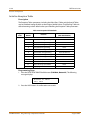
Issue
Release Date
1.0
8-05
Changes
Page
Initial Release
--
LIFE SUPPORT APPLICATIONS POLICY
VODAVI Technology, Inc. products are not authorized for and should not be used within Life
Support applications. Life Support systems are equipment intended to support or sustain life
and whose failure to perform when properly used in accordance with instructions provided can
be reasonably expected to result in significant personal injury or death.
VODAVI Technology, Inc. warranty is limited to replacement of defective components and
does not cover injury to persons or property or other consequential damages.
Copyright © 2005 VODAVI Technology, Inc.
All Rights Reserved
This material is copyrighted by VODAVI Technology, Inc., and may be duplicated by Authorized
Dealers only. Any unauthorized reproductions, use or disclosure of this material, or any part
thereof, is strictly prohibited and is a violation of the Copyright Laws of the United States
(17 U.S.C. Section 101 et. seq.).
VODAVI reserves the right to make changes in specifications at any time and without notice. The
information furnished by VODAVI in this material is believed to be accurate and reliable, but is
not warranted to be true in all cases.
STARPLUS™ is a registered trademark of VODAVI Technology, Inc.
mlj/2005
Contents
i
Contents
1
Introduction
General Description .................................................................................................... 1-3
System Features ................................................................................................................................ 1-4
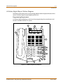
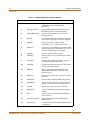
Digital Keyset Telephones ............................................................................................................. 1-5
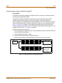
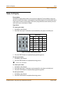
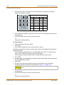
24-Button Digital Keyset / Button Diagram ............................................................................ 1-7
2
Features and Operation
About This Manual ...................................................................................................... 2-3
Content Summary ............................................................................................................................ 2-3
Manual Format & Description ...................................................................................................... 2-4
911 Feature ................................................................................................................. 2-5
911 Alert ............................................................................................................................................... 2-6
Enhanced 911 Integration ............................................................................................................. 2-7
Enhanced 911 Power Failure Station ......................................................................................... 2-8
Account Codes ............................................................................................................ 2-8
Account Codes - Forced ................................................................................................................. 2-9
Account Codes - Traveling COS (Verified) ................................................................................ 2-10
Initialize Verified Account Code Table ...................................................................................... 2-13
Print Verified Account Codes ....................................................................................................... 2-13
Answering Machine Emulation .................................................................................. 2-14
Attendant Assignment/Features ............................................................................... 2-15
Automatic Privacy ....................................................................................................... 2-16
Background Music ...................................................................................................... 2-16
Back Light Display ...................................................................................................... 2-17
Battery Backup (Memory) .......................................................................................... 2-18
Baud Rate Assignments .............................................................................................. 2-19
Call Back ...................................................................................................................... 2-20
Manual Callback ................................................................................................................................ 2-20
Call Back Button Flash Rate ........................................................................................................... 2-21
Automatic Call Back Timer ............................................................................................................ 2-21
Auto Call Back - BLF Flash Rate .................................................................................................... 2-22
Call Coverage .............................................................................................................. 2-22
Call Coverage Ring Timer ............................................................................................................... 2-24
Call Forward ................................................................................................................ 2-25
Call Forwarding ................................................................................................................................. 2-25
Call Forward - All Calls ..................................................................................................................... 2-27
Call Forward - Busy ........................................................................................................................... 2-28
Call Forward - Busy / No Answer ................................................................................................. 2-29
Call Forward - Follow Me ............................................................................................................... 2-30
Call Forward - No Answer .............................................................................................................. 2-31
Call Forward - External (Off-Net) ................................................................................................. 2-32
STARPLUS STSe - Programming & Operations Manual
August 2005
ii
Contents
Call Forward Button Flash Rate .................................................................................................... 2-33
Call Forward Display ........................................................................................................................ 2-34
Call Forward - Preset ................................................................................................... 2-34
Preset Call Forward - Station ........................................................................................................ 2-35
Preset Call Forward - CO Line ....................................................................................................... 2-39
Preset Forward Voice Mail ID ........................................................................................................ 2-41
Preset Forward Timer (Incoming Call to a Destination) ...................................................... 2-42
Calling Forward Override ........................................................................................... 2-43
Calling Station Handsfree Mode Override ................................................................ 2-43
Calling Station Tone Mode Override ......................................................................... 2-43
Call Park ....................................................................................................................... 2-44
Call Park - System .............................................................................................................................. 2-44
Call Park Recall Timer ...................................................................................................................... 2-45
Call Park - Personal ........................................................................................................................... 2-45
Call Park - Station .............................................................................................................................. 2-46
Call Pickup ................................................................................................................... 2-47
Directed Call Pickup ......................................................................................................................... 2-49
Group Call Pickup ............................................................................................................................. 2-49
Call Transfer ................................................................................................................ 2-50
Ringback on Transfer ....................................................................................................................... 2-52
Unanswered CO Call Transfer ....................................................................................................... 2-53
Camp On ...................................................................................................................... 2-54
Camp On Button Flash Rate .......................................................................................................... 2-55
Camp On Recall ................................................................................................................................. 2-55
Card Slot Programming .............................................................................................. 2-55
Centrex/PBX ................................................................................................................ 2-57
CO / PBX Programming .................................................................................................................. 2-57
Off-Hook Preference ........................................................................................................................ 2-58
Private Line Appearance ................................................................................................................ 2-58
Programming , #, and Hook-Flashes into Speed Dial ....................................................... 2-58
Centrex/PBX Flash ............................................................................................................................ 2-58
Centrex/PBX Flash Timer ................................................................................................................ 2-59
Centrex/PBX Transfer ...................................................................................................................... 2-59
PBX Dialing Codes ............................................................................................................................ 2-60
Class Of Service ........................................................................................................... 2-61
Class of Service - CO Line ............................................................................................................... 2-62
Station Day Class of Service .......................................................................................................... 2-63
Station Night Class of Service ....................................................................................................... 2-64
CO Flexible Port Assignment ..................................................................................... 2-66
CO Line - Access ........................................................................................................... 2-67
CO Line Attributes ...................................................................................................... 2-68
Initialize CO Line Attributes .......................................................................................................... 2-68
Print CO Line Attributes ................................................................................................................. 2-70
CO Line DTMF Sending ............................................................................................... 2-71
DTMF / Dial Pulse Programming ................................................................................................. 2-71
STARPLUS STSe - Programming & Operations Manual
August 2005
Contents
iii
DTMF On/Off Time Operation ...................................................................................................... 2-72
CO Line Group ............................................................................................................. 2-73
Line Group Access - Station .......................................................................................................... 2-73
CO Line Group Programming ....................................................................................................... 2-74
CO Line Group Queuing .............................................................................................. 2-75
CO Line - Identification ............................................................................................... 2-76
CO Line Identification Display ...................................................................................................... 2-76
CO Line - Incoming Ringing Assignment .................................................................. 2-78
CO Line Ringing Assignments ...................................................................................................... 2-78
Incoming CO Line Ringing - Setting Flash Rate ..................................................................... 2-80
Display Ring Assignments ............................................................................................................. 2-81
Release Timer ..................................................................................................................................... 2-82
Reseize Timer ..................................................................................................................................... 2-83
Guard Timer ........................................................................................................................................ 2-83
Seize Timer .......................................................................................................................................... 2-84
Transmit Volume ............................................................................................................................... 2-84
CO Line Loop and Pool Buttons ................................................................................. 2-85
In-Use Hold (I-Hold) Flash Rate .................................................................................................... 2-87
CO Line - Loop Supervision ........................................................................................ 2-88
Loop Supervision Programming ................................................................................................. 2-88
CO Line Loop Supervision - Forced Disconnect .................................................................... 2-89
SLT Loop Supervision Programming ......................................................................................... 2-89
CO Line - Queue ........................................................................................................... 2-91
Line Queuing ...................................................................................................................................... 2-91
CO Line Queue Button Flash Rate ............................................................................................... 2-93
CO Line - Ringing Options .......................................................................................... 2-93
Transfer CO Ringing ......................................................................................................................... 2-95
Recall CO Ringing ............................................................................................................................. 2-95
Queued CO Ringing Flash Rate .................................................................................................... 2-96
Reminder Ring Timer ....................................................................................................................... 2-96
CO Direction ....................................................................................................................................... 2-97
CO Port Parameters and Feature Codes .................................................................... 2-98
Initialize CO Port Assignments / Flexible Numbering Assignments .............................. 2-98
Print CO Port Parameters and Feature Codes ........................................................................ 2-98
CO Ring Detect Timer ................................................................................................. 2-99
CO Tolerance ............................................................................................................... 2-100
Conference .................................................................................................................. 2-101
Conference Enable/Disable .......................................................................................................... 2-101
Conference / DISA Timer ................................................................................................................ 2-102
Conference Combinations ............................................................................................................ 2-103
Cordless Key Telephone Unit Feature Button .......................................................... 2-105
Database Administration ........................................................................................... 2-106
Administration Access .................................................................................................................... 2-106
Administration Password ............................................................................................................... 2-108
Database Printout (Dump) ......................................................................................... 2-109
STARPLUS STSe - Programming & Operations Manual
August 2005
iv
Contents
Daylight Saving Time ................................................................................................. 2-110
Dial Pulse Sending ...................................................................................................... 2-111
Dial Pulse Parameters ...................................................................................................................... 2-111
Pulse Dial Inter-Digit Timer ........................................................................................................... 2-111
Pulse-to-Tone Switchover ............................................................................................................. 2-112
Direct Inward Dialing .................................................................................................. 2-112
DID Phone Number .......................................................................................................................... 2-114
Name Assigned to DID Number .................................................................................................. 2-114
Erasing a DID Table Entry ............................................................................................................... 2-115
DID/ICLID Ringing Assignments .................................................................................................. 2-116
View DID/ICLID Ringing Assignments ....................................................................................... 2-117
Preset Call Forward Destination - Day/Night/Special .......................................................... 2-118
Preset Forward Voice Mail ID ........................................................................................................ 2-119
Preset Forward Timer (Incoming Call to a Destination) ...................................................... 2-120
Music-On-Hold (per CO Line) ....................................................................................................... 2-121
Universal Night Answer (UNA) / Universal Day Answer (UDA) ........................................ 2-122
DID Digits ............................................................................................................................................. 2-123
DID Incoming Signaling ................................................................................................................. 2-124
DID/TIE Signaling .............................................................................................................................. 2-124
DID Collect Timer .............................................................................................................................. 2-126
Initialize DID-TIE Parameters ........................................................................................................ 2-127
Print DID-TIE Parameters ................................................................................................................ 2-128
Direct Inward System Access (DISA) .......................................................................... 2-129
DISA Access Code ............................................................................................................................. 2-129
DISA Programming .......................................................................................................................... 2-129
DISA Call Forwarding ....................................................................................................................... 2-130
DISA CO-to-CO ................................................................................................................................... 2-131
Direct Station Selection / Busy Lamp Field ............................................................... 2-132
Direct Transfer Mode .................................................................................................. 2-133
Directory Dial .............................................................................................................. 2-134
Initialize Directory Dial Table Parameters ................................................................................ 2-138
Print Directory Dial Table Parameters ....................................................................................... 2-139
Dial-By-Name ..................................................................................................................................... 2-140
Distinctive Ringing ..................................................................................................... 2-141
CO Line Distinctive Ring Tone ...................................................................................................... 2-141
Enabling/Disabling CO Line Distinctive Ring Tone .............................................................. 2-143
Distinctive Ring Tone - Station .................................................................................................... 2-143
Do Not Disturb / Page Block ....................................................................................... 2-147
One-Time Do Not Disturb .............................................................................................................. 2-149
Do Not Disturb Button Flash Rate ............................................................................................... 2-150
Do Not Disturb - DSS/BLF Flash Rate ......................................................................................... 2-150
Door Box ...................................................................................................................... 2-151
Executive Override ..................................................................................................... 2-152
Executive Override - Enable/Disable ......................................................................................... 2-152
Executive Override Blocking ......................................................................................................... 2-154
STARPLUS STSe - Programming & Operations Manual
August 2005
Contents
v
Executive Override Warning Tone .............................................................................................. 2-156
Barge-In Warn Tone ......................................................................................................................... 2-157
Executive/Secretary Pairs ........................................................................................... 2-158
External Day Ring ....................................................................................................... 2-159
External Night Ring ..................................................................................................... 2-159
Fax Detect .................................................................................................................... 2-160
Fixed Station/Port Number ........................................................................................ 2-162
Flash Rates (Programmable) ...................................................................................... 2-162
Flexible Button Function Assignment ....................................................................... 2-163
Display Flexible Buttons ................................................................................................................. 2-168
Flexible Numbering .................................................................................................... 2-171
Station Port Inquiry .......................................................................................................................... 2-172
Group Listening .......................................................................................................... 2-172
Headset Mode ............................................................................................................. 2-173
Hold - Exclusive ........................................................................................................... 2-176
Exclusive Hold Flash Rate ............................................................................................................... 2-176
Exclusive Hold Recall Timer ........................................................................................................... 2-177
Hold - Preference ........................................................................................................ 2-177
Hold - System .............................................................................................................. 2-178
System Hold Flash Rate .................................................................................................................. 2-178
System Hold Recall Timer .............................................................................................................. 2-178
Hot Keypad .................................................................................................................. 2-179
Hot Line / Ring Down .................................................................................................. 2-179
Hunt Groups ................................................................................................................ 2-179
Station / Pilot / Pilot All Ring -- Hunting Assignments ........................................................ 2-180
Overflow ............................................................................................................................................... 2-181
Initialize Hunt Group Parameters ................................................................................................ 2-182
Print Hunt Group Parameters ....................................................................................................... 2-183
Idle Speaker Mode ...................................................................................................... 2-183
In and Out Button ....................................................................................................... 2-184
Incoming Calling Line Identification ......................................................................... 2-185
Intercom ...................................................................................................................... 2-185
Intercom Calling ................................................................................................................................ 2-187
Incoming Intercom Ringing Flash Rate .................................................................................... 2-188
Intercom Signaling Select .............................................................................................................. 2-188
Intercom Transfer ............................................................................................................................. 2-189
Inter-Digit Time-Out ................................................................................................... 2-189
ISDN ............................................................................................................................. 2-190
Name/Number Display When Using PRI .................................................................................. 2-191
Outbound DID Number on PRI .................................................................................................... 2-195
ISDN Programming - Page A ...................................................................................... 2-197
Primary Rate Interface (PRI) CO Type ......................................................................................... 2-197
Framing ................................................................................................................................................ 2-198
Power .................................................................................................................................................... 2-198
Directory Number - PRI ................................................................................................................... 2-198
STARPLUS STSe - Programming & Operations Manual
August 2005
vi
Contents
Max Out I-Frames .............................................................................................................................. 2-199
Leading 1 ............................................................................................................................................. 2-199
Leading 011 ........................................................................................................................................ 2-200
PRI 7/11 Digit Number Plan .......................................................................................................... 2-200
Calling Number ................................................................................................................................. 2-201
Loopback ............................................................................................................................................. 2-201
ISDN Programming - Page B ...................................................................................... 2-202
Maximum Number Retransmission ........................................................................................... 2-203
Maximum Octets ............................................................................................................................... 2-203
Maximum TEI Request .................................................................................................................... 2-204
Maximum XID Retransmission ..................................................................................................... 2-204
T-200 ...................................................................................................................................................... 2-204
Minimum TEI ID Check Message ................................................................................................. 2-205
Minimum TEI ID Request ................................................................................................................ 2-205
Message Exchange Timer .............................................................................................................. 2-205
Minimum XID Retransmission ...................................................................................................... 2-206
Inter-Digit T / O .................................................................................................................................. 2-206
Set-Up Timer ....................................................................................................................................... 2-207
Disconnect Timer .............................................................................................................................. 2-207
Release Request ................................................................................................................................ 2-207
Link Disconnect ................................................................................................................................. 2-208
Call Proceeding .................................................................................................................................. 2-208
Connect Request ............................................................................................................................... 2-208
Restart Request Timer ..................................................................................................................... 2-209
Initialize ISDN Parameters ............................................................................................................. 2-209
Print ISDN Parameters ..................................................................................................................... 2-210
Keyset Mode ................................................................................................................ 2-212
Last Number Redial .................................................................................................... 2-215
LCD ............................................................................................................................... 2-215
LCD Display - Contrast .................................................................................................................... 2-215
LCD Interactive Display .................................................................................................................. 2-216
LCOB Loop Length ...................................................................................................... 2-223
Leading Digit ............................................................................................................... 2-223
Least Cost Routing ...................................................................................................... 2-224
Light Control ............................................................................................................... 2-224
Message Wait .............................................................................................................. 2-225
Message Waiting Reminder Tone .............................................................................. 2-226
Music-On-Hold ............................................................................................................ 2-226
MOH Assignments ............................................................................................................................ 2-227
Music-On-Hold - Enable/Disable ................................................................................................. 2-227
Music-On-Hold (per CO Line) ....................................................................................................... 2-228
Mute Key ...................................................................................................................... 2-229
Muted Ring .................................................................................................................. 2-230
Name In Display .......................................................................................................... 2-231
Name / Number Display At Idle ................................................................................................... 2-232
STARPLUS STSe - Programming & Operations Manual
August 2005
Contents
vii
Name/Number Translation Table .............................................................................. 2-233
Night Service ............................................................................................................... 2-235
Automatic/Manual Operation ...................................................................................................... 2-235
Day of Week Programming ........................................................................................................... 2-236
Automatic Night Mode Operation ............................................................................................. 2-236
External Night Ringing .................................................................................................................... 2-236
Manual Operation ............................................................................................................................ 2-236
Night Class of Service (COS) .......................................................................................................... 2-236
Night Ringing Assignments .......................................................................................................... 2-237
Universal Night Answer (UNA) ..................................................................................................... 2-237
Weekly Night Mode Schedule ...................................................................................................... 2-237
Off-Hook Signaling ..................................................................................................... 2-237
Off-Hook Voice Over ................................................................................................... 2-238
Outside Calls ................................................................................................................ 2-241
Paging .......................................................................................................................... 2-242
Paging Access .................................................................................................................................... 2-243
Paging - Meet Me .............................................................................................................................. 2-244
Paging Time-Out Timer .................................................................................................................. 2-245
Page Warning Tone .......................................................................................................................... 2-245
Paging Zone(s) ................................................................................................................................... 2-246
Pause Timer ................................................................................................................. 2-247
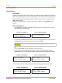
Personal Messages ...................................................................................................... 2-248
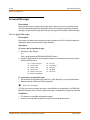
Pre-assigned Messages ................................................................................................................... 2-248
Custom Messages ............................................................................................................................. 2-249
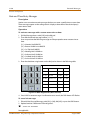
Date and Time Entry Messages .................................................................................................... 2-250
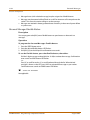
Scrollable Canned Messages ........................................................................................................ 2-251
Personal Messages Flexible Button ............................................................................................ 2-252
Preferred Line Answer ................................................................................................ 2-253
Privacy Release ........................................................................................................... 2-254
Per CO Line Option ........................................................................................................................... 2-254
Per Station Option ............................................................................................................................ 2-256
Private Line .................................................................................................................. 2-258
Recall ............................................................................................................................ 2-258
Answering a Recall ........................................................................................................................... 2-258
Transfer Recall Timer ....................................................................................................................... 2-258
Repeat Redial .............................................................................................................. 2-259
Relay Programming .................................................................................................... 2-260
Remote Administration .............................................................................................. 2-261
Program Mode Entry ....................................................................................................................... 2-261
Modem Answer Timer ..................................................................................................................... 2-261
Database Upload/Download ........................................................................................................ 2-262
Remote System Monitor And Maintenance .............................................................. 2-262
Maintenance ....................................................................................................................................... 2-262
Monitor ................................................................................................................................................. 2-262
Ring Down / Hot Line / Off-Hook Preference ............................................................ 2-263
STARPLUS STSe - Programming & Operations Manual
August 2005
viii
Contents
Save Number Redial (SNR) ......................................................................................... 2-266
School Zone ................................................................................................................. 2-267
Single Line Telephone ................................................................................................ 2-270
Compatibility ...................................................................................................................................... 2-270
SLT DTMF Receiver Timer .............................................................................................................. 2-270
SLT Hook Flash Timer ...................................................................................................................... 2-271
SLT Hook Flash Bounce Timer ...................................................................................................... 2-271
Software Version (MBU) ............................................................................................. 2-272
Speakerphone ............................................................................................................. 2-272
Speakerphone Options ................................................................................................................... 2-272
Speakerphone Operation .............................................................................................................. 2-274
Speed Dial .................................................................................................................... 2-275
Station Speed Dial Numbers ........................................................................................................ 2-275
System Speed Dial Access ............................................................................................................. 2-276
Speed Bins - Chaining ..................................................................................................................... 2-278
Initialize System/Station Speed Numbers ............................................................................... 2-278
Print System Speed Numbers ...................................................................................................... 2-279
Station Attributes ....................................................................................................... 2-280
Initialize Station Attributes ............................................................................................................ 2-280
Print Station Attributes ................................................................................................................... 2-282
Station Identification ................................................................................................. 2-283
Station ID Lock ................................................................................................................................... 2-285
Station Message Detail Recording ............................................................................ 2-286
SMDR Enable/Disable ...................................................................................................................... 2-288
Long Distance - All Calls ................................................................................................................. 2-288
Character Print Assignment .......................................................................................................... 2-289
Baud Rate Display ............................................................................................................................. 2-289
SMDR Port Assignments ................................................................................................................. 2-289
SMDR Call Qualification Timer ..................................................................................................... 2-290
Station Relocation ...................................................................................................... 2-291
System Parameters ..................................................................................................... 2-292
Initialize System Parameters ......................................................................................................... 2-292
Print System Parameters ................................................................................................................ 2-296
System Reset ............................................................................................................... 2-298
T-1 Alarm Programming ............................................................................................. 2-299
Enable/Disable (Carrier Loss Alarm) ........................................................................................... 2-299
Blue Alarm ........................................................................................................................................... 2-300
Yellow Alarm ...................................................................................................................................... 2-301
Red Alarm ............................................................................................................................................ 2-301
Bipolar Variations Alarm ................................................................................................................. 2-302
Frame Slip Alarm ............................................................................................................................... 2-302
Data Errors Alarm .............................................................................................................................. 2-303
Clear Alarm .......................................................................................................................................... 2-303
Minor Alarm ........................................................................................................................................ 2-304
Major Alarm ........................................................................................................................................ 2-304
STARPLUS STSe - Programming & Operations Manual
August 2005
Contents
ix
Time Period ......................................................................................................................................... 2-305
Attendant Display - T-1 Alarms .................................................................................................... 2-305
T-1 Trunking ................................................................................................................ 2-306
T-1 Signaling Type ............................................................................................................................ 2-306
T-1 Ringback Option ........................................................................................................................ 2-308
T-1 Dial Tone Option ....................................................................................................................... 2-308
Wink Timer .......................................................................................................................................... 2-309
T-1 Collect Timer ............................................................................................................................... 2-310
T-1 Incoming Signaling ................................................................................................................... 2-310
T-1 Framing Type .............................................................................................................................. 2-311
Tenant Groups ............................................................................................................ 2-312
Enable/Disable the Tenant Groups Feature ............................................................................ 2-312
Attendant Station Assignment for Tenant Groups .............................................................. 2-313
Station Assignment to a Tenant Group .................................................................................... 2-313
CO Line Assignments for Tenant Groups ................................................................................. 2-314
Incoming Ring Assignments ......................................................................................................... 2-315
CO Line Sharing ................................................................................................................................. 2-316
Text Messaging (Silent Response) ............................................................................. 2-316
Toll Restriction ............................................................................................................ 2-318
Entering Toll Table ........................................................................................................................... 2-320
Allow Table ......................................................................................................................................... 2-321
Deny Table .......................................................................................................................................... 2-323
Special Table ....................................................................................................................................... 2-324
Display Toll Table Entries ............................................................................................................... 2-325
Initialize Exception Tables ............................................................................................................. 2-326
Print Exception Tables .................................................................................................................... 2-327
Toll Restriction Related Items ....................................................................................................... 2-328
Uniform Call Distribution ........................................................................................... 2-329
Universal Day/Night Answer ...................................................................................... 2-329
Universal Day Answer (UDA) ........................................................................................................ 2-330
Universal Night Answer (UNA) ..................................................................................................... 2-331
Virtual Stations ........................................................................................................... 2-332
Voice Mail .................................................................................................................... 2-333
Alternate Voice Mail Group ........................................................................................................... 2-334
Standard Leave Mail Index Entry ................................................................................................. 2-334
Retrieve Mail Index Entry ............................................................................................................... 2-335
Station Assignments ........................................................................................................................ 2-335
No Answer Leave Mail Index Entry ............................................................................................. 2-336
Busy Leave Mail Index Entry ......................................................................................................... 2-336
VMID Station Numbers ................................................................................................................... 2-337
VM Transfer with ID Digits ............................................................................................................. 2-337
VM Tone Mode Calling Option .................................................................................................... 2-338
Voice Mail ID Translation ................................................................................................................ 2-339
Message Waiting Indication ......................................................................................................... 2-340
Message Wait / VM Button Flash Rate ....................................................................................... 2-341
STARPLUS STSe - Programming & Operations Manual
August 2005
x
Contents
Voice Mailbox Button ...................................................................................................................... 2-342
Voice Mail Group Button ................................................................................................................ 2-342
Voice Mail Group Access ................................................................................................................ 2-342
Initialize Voice Mail Group Parameters ..................................................................................... 2-343
Print Voice Mail Group Parameters ............................................................................................ 2-344
Voice Mail In-Band Features ...................................................................................... 2-345
In-Band Signaling Integration ...................................................................................................... 2-345
Voice Mail In-Band Digits ............................................................................................................... 2-346
Voice Mail Transfer / Forward ....................................................................................................... 2-346
Voice Mail Broker .............................................................................................................................. 2-347
Voice Mail ID Digit Length ............................................................................................................. 2-347
Voice Mail Modem Access ............................................................................................................. 2-348
Voice Mail One-Touch Recording .............................................................................. 2-349
One-Touch Recording Warning Tone ....................................................................................... 2-351
Voice Mail Outpulsing Table ...................................................................................... 2-351
Voice Mail In-Band Signaling ........................................................................................................ 2-351
Voice Mail Disconnect Table ......................................................................................................... 2-353
Voice Mail System Message Wait Indications ........................................................... 2-354
Volume Control ........................................................................................................... 2-355
3
Attendant Features and Operation
Introduction ................................................................................................................ 3-3
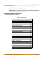
Attendant Features - Index ........................................................................................ 3-4
911 Alert ...................................................................................................................... 3-5
Attendant CO Line External (Off-Net) Forward ........................................................ 3-6
Attendant Custom Message ....................................................................................... 3-7
Attendant Day/Night/Special .................................................................................... 3-8
Attendant Directory List Programming .................................................................... 3-9
Attendant Disable Outgoing CO Line ........................................................................ 3-12
Attendant Override .................................................................................................... 3-13
Attendant Setting Time and Date ............................................................................. 3-14
Attendant Station Assignment .................................................................................. 3-15
Attendant Unavailable ............................................................................................... 3-16
Attendant Voice Mail Alarm Clear ............................................................................. 3-17
DSS/BLF Console with Map ........................................................................................ 3-17
Busy Lamp Field Indicators ........................................................................................................... 3-17
Direct Station Calling ....................................................................................................................... 3-17
Release Key ......................................................................................................................................... 3-17
Transfer Search .................................................................................................................................. 3-17
Mapping Options .............................................................................................................................. 3-18
Station ID for DSS/BLF Console With Map ............................................................................... 3-21
Display Timer .............................................................................................................. 3-21
ICLID Call Management Tables .................................................................................. 3-22
Answered Call Management Table ............................................................................................ 3-22
Unanswered Call Management Table ....................................................................................... 3-23
STARPLUS STSe - Programming & Operations Manual
August 2005
Contents
xi
Recall ............................................................................................................................ 3-24
Attendant Recall Timer ................................................................................................................... 3-24
Release Button ............................................................................................................ 3-24
Speed Dial - System Storing ....................................................................................... 3-25
4
Uniform Call Distribution
Uniform Call Distribution ........................................................................................... 4-3
UCD Calls In Queue Status Display ............................................................................................. 4-3
Alternate UCD Group Assignments ........................................................................................... 4-4
Incoming CO Direct Ringing ......................................................................................................... 4-4
Message Interval Timer ................................................................................................................... 4-5
No-Answer Recall Timer ................................................................................................................. 4-5
No-Answer Retry Timer .................................................................................................................. 4-6
Overflow Station Assignment ...................................................................................................... 4-6
Overflow Station Forwarding ....................................................................................................... 4-7
Overflow Timer .................................................................................................................................. 4-8
Primary Agent Assignments ......................................................................................................... 4-8
Primary Recorded Announcement ............................................................................................. 4-9
Recorded Announcements ........................................................................................................... 4-9
Recorded Announcement Tables ............................................................................................... 4-10
Ring Timer ........................................................................................................................................... 4-11
Secondary Recorded Announcement ....................................................................................... 4-12
UCD Available/Unavailable ........................................................................................................... 4-12
Wrap-up Timer ................................................................................................................................... 4-14
Initialize UCD Group Parameters ................................................................................................ 4-15
Print UCD Group Parameters ........................................................................................................ 4-16
A
ICLID / Caller ID
Introduction ................................................................................................................ A-3
Functional Performance ............................................................................................. A-4
Caller ID Name/Number ............................................................................................. A-4
Calling Number/Name Display .................................................................................................... A-5
Incoming Number/Name for SMDR Records .......................................................................... A-6
Local Name Translation .................................................................................................................. A-6
ICLID Programming .................................................................................................... A-6
Enable/Disable ................................................................................................................................... A-7
Name in Display ................................................................................................................................ A-7
Baud Rate Display ............................................................................................................................. A-8
Port Assignment ................................................................................................................................ A-8
Ring Delay Timer ............................................................................................................................... A-9
Initialize ICLID-DID Tables .............................................................................................................. A-10
Print ICLID - DID Tables ................................................................................................................... A-12
ICLID Call Management Tables .................................................................................. A-14
Answered Call Management Table ............................................................................................ A-14
Unanswered Call Management Table ....................................................................................... A-15
STARPLUS STSe - Programming & Operations Manual
August 2005
xii
B
Contents
Least Cost Routing
Introduction ................................................................................................................ B-3
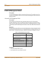
LCR Tables ........................................................................................................................................... B-3
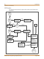
LCR Flowchart .................................................................................................................................... B-4
Operation (When LCR is Enabled) ............................................................................................... B-5
Programming LCR Tables ........................................................................................... B-5
3-Digit Area / Office Code Table .................................................................................................. B-6
6-Digit Office Code Table ............................................................................................................... B-7
Exception Code Table ..................................................................................................................... B-8
Route List Table ................................................................................................................................. B-8
Insert/Delete Table ........................................................................................................................... B-10
Daily Start Time Table ..................................................................................................................... B-11
Weekly Schedule Table ................................................................................................................... B-13
LCR Routing for Toll Information ................................................................................................ B-14
LCR Call Progress ............................................................................................................................... B-14
Default LCR Database ...................................................................................................................... B-15
Forced Least Cost Routing (LCR) ................................................................................................. B-15
LCR Class of Service (COS) ............................................................................................................. B-16
Enable/Disable Least Cost Routing ............................................................................................ B-18
Call Cost Display ................................................................................................................................ B-18
Initialize LCR Tables .......................................................................................................................... B-19
Print LCR Tables ................................................................................................................................. B-20
LCR Printout ........................................................................................................................................ B-21
C
Flash-Based Voice Mail
Introduction ................................................................................................................ C-3
System Capabilities .......................................................................................................................... C-3
Basic Features ..................................................................................................................................... C-3
Programming the Voice Mail System ........................................................................ C-4
Card Slot Programming .................................................................................................................. C-4
Recorded Announcement Tables ............................................................................................... C-5
Programming Devices for Flash-based Voice Mail System ............................................... C-6
Programming System Functions Via Telephone ................................................................... C-7
Programming System Functions Via Computer .................................................................... C-17
Voice Prompts .................................................................................................................................... C-38
Remote Programming & Maintenance Connection ............................................................ C-43
User Operations .......................................................................................................... C-44
How to Use the Voice Mail System ............................................................................................. C-44
Getting Started .................................................................................................................................. C-44
Message Options .............................................................................................................................. C-45
Mailbox Greeting Options ............................................................................................................. C-49
Passwords ............................................................................................................................................ C-51
Outcall Notification .......................................................................................................................... C-51
Direct Transfer .................................................................................................................................... C-51
STARPLUS STSe - Programming & Operations Manual
August 2005
Contents
D
xiii
Hard Drive-Based Voice Mail
Introduction ................................................................................................................ D-3
Basic Features ..................................................................................................................................... D-3
Programming the Voice Mail System ........................................................................ D-4
Card Slot Programming .................................................................................................................. D-4
Recorded Announcement Tables ............................................................................................... D-5
Programming Devices for Hard Drive-based Voice Mail System .................................... D-6
Programming System Functions Via Computer ................................................................... D-8
Programming System Functions Via Telephone ................................................................... D-36
Voice Prompts .................................................................................................................................... D-43
System Maintenance ....................................................................................................................... D-44
Troubleshooting ............................................................................................................................... D-54
User Operations .......................................................................................................... D-56
How to Use the Voice Mail System ............................................................................................. D-56
Getting Started .................................................................................................................................. D-57
Message Options .............................................................................................................................. D-58
Mailbox Options ................................................................................................................................ D-61
E
Customer Database Programming
Introduction ................................................................................................................ E-3
Program Mode Entry (Key Station) ............................................................................ E-6
Program Mode Entry (Data Terminal or PC) ............................................................. E-6
Initialization ................................................................................................................ E-6
Database Programming Worksheets ........................................................................ E-7
Database Upload/Download Routine ....................................................................... E-7
Upload/Download through Remote Administration .......................................................... E-7
F
Quick Reference
Flash Code Index ......................................................................................................... F-3
Default Numbering Plan ............................................................................................ F-16
STARPLUS STSe - Programming & Operations Manual
August 2005
xiv
STARPLUS STSe - Programming & Operations Manual
Contents
August 2005
1
Introduction
This manual provides the information necessary to operate and maintain the STSe
System. The described features are based on the current software release. If any of
these features do not work on your system, call your sales representative regarding
upgrade of your system.
STARPLUS STSe - Programming & Operations Manual
August 2005
»
»
»
»
»
»
»
N O T E S
»
»
»
»
»
»
»
General Description
1-3
Introduction
General Description
Allows Flexibility and Software Control
The STSe Digital Key Telephone System is a fully digital hybrid Key Telephone System,
designed to meet the telecommunication needs of small to medium-sized business offices.
The system has been designed to allow a high level of software control over the system's
hardware. The software incorporates a vast array of features and capabilities including PC
Database Administration and Least Cost Routing.
Incorporates Command Processing & Voice Switching
The STSe System incorporates state of the art digital technology for command processing
and voice switching, using a Pulse Code Modulation/Time Division Multiplexing (PCM/TDM,
"A" law or "U" law) distributed switching matrix.
Supports Multiple Devices
The STSe system supports a combination of Digital Keysets and wireless terminals as well as
analog single line devices. With the keysets, commonly used features are activated by direct
button selection. Additionally, many functions may be accessed by dialing specific codes or
optionally, by assigning these dial codes to Flexible Buttons on the keyset. In addition to key
telephones, an array of optional terminals is available.
With the flexibility of the STSe extensive feature content, and the capability to use an array of
instruments, the STSe can be tailored to meet the short and long term needs of the most
demanding customer requirements.
STARPLUS STSe - Programming & Operations Manual
August 2005
1-4
General Description
Introduction
System Features
This page displays a condensed list of the extensive features available in the STSe System:
911 Feature
Account Codes
Answering Machine Emulation
Attendant Assignment / Features
Automatic Privacy
Background Music
Battery Back-Up (Memory)
Baud Rate Assignments
Call Back
Call Coverage
Call Forward
Call Forward - Preset
Calling Forward Override
Calling Station Handsfree Mode Override
Calling Station Tone Mode / Override
Call Park - Station
Call Park - System
Call Pickup
Call Transfer
Camp On
Centrex/PBX
Class Of Service (COS)
CO Line - Access
CO Line Attributes
CO Line DTMF Sending
CO Line Group
CO Line - Identification
CO Line - Incoming Ringing Assignment
CO Line Loop and Pool Buttons
CO Line - Loop Supervision
CO Line - Queue
CO Line - Ringing Options
CO Port Parameters
CO Ring Detect Timer
Conference
Cordless Key Telephone Unit Feature Button
Database Administration
Database Printout (Dump)
Dial By Name
Dial Pulse Sending
Direct Inward System Access (DISA)
Direct Station Selection / Busy Lamp Field
Direct Transfer Mode
Directory Dial
Distinctive Ringing
Do Not Disturb
Executive Override
Executive / Secretary Pairs
External Day Ring
External Night Ring
Fixed Station/Port Number
Flash Rates (Programmable)
Flexible Button Assignment
Flexible Numbering
Group Listening
Headset Mode
Hold - Exclusive
Hold - Preference
Hold - System
Hot Keypad
Hot Line / Ring Down
Hunt Groups
ICLID / Caller ID*
Idle Speaker Mode
Incoming Calling Line Identification
Initializing - System Parameters
Intercom
Inter-Digit Time-Out
Keyset Mode
Last Number Redial
LCD - Contrast
LCD - Display
Least Cost Routing (LCR)
Message Wait
Message Waiting Reminder Tone
Music-On-Hold
Mute Key
Name In Display
Name / Number Translation Table
Night Service
Off-Hook Signaling
Off-Hook Voice Over
Outside Calls
Paging
Pause Timer
PBX Dialing Codes
Personal Messages
Preferred Line Answer
Printing - System Parameters
Privacy Release
Private Line
Recall
Repeat Redial
Relay Programming
Remote Administration*
Remote System Monitor And Maintenance*
Save Number Redial (SNR)
Single Line Telephone (SLT)
Software Version (MBU)
Speakerphone
Speed Dial
Station Attributes
Station Identification
Station Message Detail Recording
Station Relocation
Station Speed Dial Numbers
System Parameters
System Reset
System Speed Bin Access
Text Messaging (Silent Response)
Toll Restriction
Uniform Call Distribution (UCD)
Universal Day/Night Answer
Voice Mail
Voice Mail In-Band Features
Voice Mail One-Touch Recording
Voice Mail Outpulsing Table
Volume Control
* = May require additional hardware or software
General Description
1-5
Introduction
Digital Keyset Telephones
Each STSe System provides all the keys, indicators, and features described.
Handset and Speaker are located at the left side of the front panel. A handset is provided to
allow confidential conversation when desired. Lifting the handset from its cradle (going
off-hook) disengages the station’s built-in speaker. The speaker is located directly below the
center portion of the handset. The station may be operated with the handset on-hook. When
this occurs, audio is transmitted to the station user through the station’s speaker.
Flexible Buttons provide access to idle outside lines, DSS/BLF for internal stations, access
speed dial numbers and activate features. These buttons can be programmed by the
individual station user. The default flexible feature buttons are described as follows:
»
CALL BACK button lets you initiate a call back request to another busy station. As soon as
that station becomes idle, the station that left the call back request is automatically
signaled. A flexible button must be assigned to use this feature.
»
PICK-UP button lets you pick up a tone ringing intercom call, transferred, incoming, or
recalling outside call to a specific unattended station, by group or directed call pick-up.
»
DND (DO NOT DISTURB) button lets the user place their telephone into Do Not Disturb
mode to eliminate incoming outside line ringing, intercom calls, transfers and paging
announcements. The station in DND can use the telephone to make normal outgoing
calls. On Attendant stations, this button becomes the system Night Mode button. A
flexible button must be assigned to use this feature.
»
LINE QUEUE button lets you queue to an outside line when all lines in a group are busy.
Your station is placed in queue, awaiting a line in the same group to become available.
Outside Calls are announced by a tone signal repeated every 3.2 seconds. The
corresponding outside line indicator flashes slowly.
Intercom Calls can be tone ringing or voice announced. If voice announced, the receiving
station receives three tone bursts prior to the announcement. If a tone ringing call, the
receiving station hears a tone ring every 2.4 seconds.
STARPLUS STSe - Programming & Operations Manual
August 2005
1-6
General Description
Introduction
24-Button Speakerphone
The 24-button Digital Telephone has
24 flexible, dual color LEDs that can be
customized for each application.
When the flexible button are used as
DSS buttons, station status can be
seen in a single glance. When they are
used as CO/PBX/Centrex buttons, line
status is easily monitored.
This integrated speakerphone offers
call announce with hands-free
intercom and a hot keypad that allows
dialing while the phone is on-hook.
The three interactive soft keys provide
additional feature functionality.
P/N 3515
DSS Console
When the DSS Console is added, 48 additional
buttons can be used to support an attendant or
other answering position.
P/N 3510
STARPLUS STSe - Programming & Operations Manual
August 2005
General Description
1-7
Introduction
24-Button Digital Keyset / Button Diagram
The following illustration and its corresponding table describe the physical features of the
Vodavi 24-Button Digital Display Telephone (P/N 3515).
Programming Requirement
A 24-button display telephone is necessary when programming the system features and
functions available with the STSe System.
2
18
1
19
3
9
ABC
DEF
1
2
3
GHI
JKL
MNO
4
5
6
PRS
TUV
WXY
7
8
9
OPER
*
0
8
FLASH
TRANS
SPEED
CONF
MSG
FWD
MUTE
CAMP ON
ON/OFF
HOLD
6
7
5
4
#
10
11
12
VOLUME
13
16
17
15
14
Figure 1-1: 24-Button Digital Key Telephone
STARPLUS STSe - Programming & Operations Manual
August 2005
1-8
General Description
Introduction
Table 1-1: 24-Button Digital Key Telephone Buttons
NUMBER
FEATURE BUTTON
FUNCTION
1
Display
Displays information about telephone status,
dialing directories, and text message
information.
2
Message Indicator
Programmable indication for Ring Line, Voice
Mail, Message Wait, or handset operation
3
Flexible Button Keys
Used to access outside lines or access callhandling features.
4
MSG Key
Used for Auto-CallBack to a telephone which has
left a text message or to access voice messages.
5
FWD Key
Used to forward your calls to another
destination, such as a station or voice mail.
6
SPEED Key
Used to access speed dialing, save number redial
and last number redial. This button also is used
to access flexible button programming.
7
CONF Key
Used to establish conference calls.
8
TRANS Key
Used to transfer an outside call from one station
to another.
9
FLASH Key
Used to end an outside call and to restore dial
tone without hanging up receiver.
10
CAMP ON
Used to alert a busy station that an outside line is
on hold and waiting for them.
11
MUTE Key
Used to activate/deactivate MUTE function.
When activated, the party on the other end
cannot hear you.
12
HOLD Key
Used to place outside calls on hold or to retrieve
held calls.
13
ON/OFF Key
Used to make a call without lifting the handset.
14
VOLUME Key
Used to adjust level of tones, background music,
ringing, receiver volume, and display contrast.
15
Speaker
Outputs tones and voice at your extension.
16
Microphone
Used to talk with other party without using the
handset.
17
H-T-P
Used to select mode of operation: Handsfree,
Tone, or Privacy.
18
Interactive Soft Keys
Used to work in conjunction with fixed and
flexible features.
19
Headset Jack
2.5 mm Headset Jack is located on the left side of
the telephone.
STARPLUS STSe - Programming & Operations Manual
August 2005
2
Features and Operation
Detailed descriptions of the System and Station features are presented in alphabetical
order. An abbreviated feature index, that is organized in Flash code numerical
sequence, is provided in Appendix F.
STARPLUS STSe - Programming & Operations Manual
August 2005
»
»
»
»
»
»
»
N O T E S
»
»
»
»
»
»
»
About This Manual
2-3
Features and Operation
About This Manual
Content Summary
Chapters
The following chapters contain the descriptions, programming steps, and operating
procedures for the more commonly-used features and functions.
2 - Features & Operation
3 - Attendant Features & Operation
4 - Uniform Call Distribution (UCD)
Appendices
Appendices contain detailed information on how to use the more complex features available.
Worksheets and Tables are in the last two appendices for easy access to specific customer
system information and frequently-used flash and feature codes.
A - ICLID / Caller ID
B - Least Cost Routing
C - Flash-Based Voice Mail
D - Hard Drive-Based Voice Mail
E - Customer Database Programming
F - Quick Reference Tables
Flash Codes
Default Numbering Plan
STARPLUS STSe - Programming & Operations Manual
August 2005
2-4
About This Manual
Features and Operation
Manual Format & Description
This diagram explains how the Features/Operations are organized in the following chapters
and appendices. The manual format follows the basic outline as shown, but omits those
elements that do not apply to a particular Feature or Operation.
Feature / Operation
Narrative to explain the feature/operation.
Sub-Feature / Operation
Description
Narrative to explain the sub-feature/operation.
Related Information
Quick Reference
Flash XX Button X The xxxx function MUST
also be enabled.
Programming Steps
Consists of those actions required of a system
administrator to program single or multiple phones in
the system or system features using the 24-button digital
telephone.
This section assumes that you have already entered
database administrative programming using the string
of [ ][ ][3][2][2][6] (default password).
DEFAULT … Shows the system default setting.
Operation
Describes how the user operates the digital telephone.
SINGLE LINE TELEPHONE
A “Telephone” symbol appears whenever the Single Line
Telephone operation differs from the Digital Telephone.
If your single line telephone does not have a FLASH key,
quickly press and release the hookswitch when
instructed to press the FLASH key.
Conditions
»
Describes any special criteria that affects the
programming or operation of the feature.
STARPLUS STSe - Programming & Operations Manual
August 2005
911 Feature
2-5
Features and Operation
911 Feature
Description
The 911 Feature allows stations in the system to dial 911 without using an access code. 911
calls are placed on 911 marked lines. If all lines are busy, an existing call is dropped and the
911 call is placed.
When this feature is enabled, Trunk Group/LCR Access Code 9 is not available.
Related Information
Quick Reference
Flash 12
To insert [9] for Centrex 911 calls (refer to “PBX Dialing Codes”
on page 2-60).
Programming Steps
To enable/disable the 911 feature:
1. Press the 911 FEATURE flexible button (FLASH 06, Button #13). The following displays:
9 1 1 F E ATU R E
D I S A B LE D
0-1
2. Enter a 0 or 1 on the dial pad to enable/disable the use of this feature.
[0] = Disabled
[1] = Enabled
DEFAULT … Disabled
To designate the line(s) for 911 use:
1. Press FLASH and dial [40]. The following message displays:
CO L I N E AT T R I B U T E S
S E L EC T A CO L I NE R A NG E
2. Enter a valid number for the range of lines being programmed. If only one line is being
programmed, enter that number twice (001 001).
If HOLD is pressed without entering a CO line range, all CO lines are selected.
3. Press HOLD to save the entry. A confirmation tone sounds and the display updates.
Flexible button #19 (Page A) is lit. The following message displays to indicate current
programming of that line or group of lines:
XXX - XXX PAGE A
E N T E R B U T TO N N U MBE R
XXX-XXX = CO Line Range
STARPLUS STSe - Programming & Operations Manual
August 2005
2-6
911 Feature
Features and Operation
4. Press Button #15 to designate the line for 911 use.
911 TRUNK
D I S A B LE D
0-1
5. Enter a 0 or 1 on the dial pad to enable/disable this feature.
[0] = Disabled
[1] = Enabled
6. Press HOLD to save the entry. A confirmation tone sounds and the display updates.
DEFAULT … Disabled
911 Alert
Description
Any station user or Attendant who programs a flexible button for 911 ALERT (feature code
608) will be alerted of internal stations placing 911 calls. The system can store the sixteen
most recent 911 calls. Calling information includes the time/date of the call, as well as the
station number from which the call was placed.
The initial 911 Alert indications include:
Audible ringing tone
Green flashing 911 ALERT flexible button LED
Automatic LCD display of 911 call information
E911 C A LL
M M/ DD / Y Y
XX:
STA XXXX
HH:MM
XX = Index number (01-16)
Operation
Station users and Attendants can press the 911 ALERT flexible button as necessary to view
additional 911 calls’ information in the stored list. After a station user or Attendant views the
information for all 911 calls in the system list:
All users’ LEDs change to a solid red indication.
The audible ringing tone at all stations ceases.
The LCDs at all stations revert to a normal display.
The list remains available for review by pressing the 911 ALERT flexible button as necessary,
until after the messages are deleted.
To delete logged 911 Alert messages:
An Attendant uses the following steps to delete the messages on a system-wide basis.
1. Press the 911 ALERT flexible button to display the 911 call information for deletion.
2. Press FLASH to delete that message.
STARPLUS STSe - Programming & Operations Manual
August 2005
911 Feature
2-7
Features and Operation
Enhanced 911 Integration
Description
The E911 feature integrates the system to the Proctor PBX ANI-LINK product to provide
enhanced 911 service. Loop Start lines can be connected to the Proctor unit and
programmed to be 911 lines (FLASH 40, Page A, Button #15). When a 911 call is made from a
station in the system, the system will send 911XXXX (XXXX=Station # that placed the 911 call)
in DTMF format to the Proctor. If the station number is less than 4 digits, a leading 0 will
automatically be added. The Proctor unit then accesses a CO trunk and sends the information
in the proper format to the 911 Center.
This feature also provides a means to identify a power failure signal from the Proctor Unit. If a
power failure signal is detected, the KSU routes 911 calls via trunks other than those marked
for 911 use until the signal is removed.
The E911 feature ensures access to 911 by freeing a CO Line, then making a call.
If you are using Centrex lines, a 2-second setting is recommended for Guard Timer
programming (Flash 40, Page C, Button #6). This avoids situations where a line is
seized by the 911 call before an existing call is dropped, causing the emergency
call to be conferenced with the existing call.
Programming Steps
1. Press the ENHANCED 911 button (FLASH 06, Button #14). The following message
displays:
E N HA N CE D 9 11
D I S A B LE D
0-1
2. Enter a 0 or 1 on the dial pad to enable/disable the use of this feature.
[0] = Disabled
[1] = Enabled
DEFAULT … Disabled
Conditions
»
»
The 911 Feature (FLASH 06, Button #13) must be enabled for Proctor Integration to work.
»
It is recommended to have a power failure procedure in place to ensure that 911 calls are
always routed. Refer to FLASH 09, Button #7 for programming information.
Only the lines connected to the Proctor should have the 911 Enable programmed
(FLASH 40, Page A, Button #15).
STARPLUS STSe - Programming & Operations Manual
August 2005
2-8
Account Codes
Features and Operation
Enhanced 911 Power Failure Station
Description
The power failure signal is designed to be used with the normally open (NO) power failure
leads from the Proctor unit connected to an SLT port or SLA device. When the leads close in
power failure, this is detected as an off hook and 911 routing ceases to the Proctor unit. 911
calls are sent via trunks other than those marked for 911 use until the power failure lead
opens, which is detected as an on hook. 911 calls are then routed again to the Proctor unit.
Programming Steps
1. Press the E911 POWER FAILURE STATION button (FLASH 09, Button #7). The following
message displays:
PROCTOR 911 P/ F
# ## #
####
2. Enter a valid SLT station number (100-8999) to be used as the power failure station.
3. Press HOLD to save the entry. A confirmation tone sounds.
Conditions
»
»
»
During a power failure, 911 calls are sent via trunks other than those marked for 911.
During a power failure, the station’s digit information is not sent.
The feature requires either an SLT port or an SLA port for the integration to work.
Account Codes
Description
An account code is the last field within Station Message Detail Recording (SMDR), that
provides tracking capabilities for specific calls by entering a verified/non-verified, variable
length (up to 12 digits) identifier.
The use of forced Account Codes is optional, offered on a system-wide basis.
Related Information
Quick Reference
Flash 21
Button 1
The SMDR function MUST be enabled for the Forced Account
Code feature to operate (refer to “SMDR Enable/Disable” on
page 2-288).
STARPLUS STSe - Programming & Operations Manual
August 2005
Account Codes
2-9
Features and Operation
Account Codes - Forced
Description
The STSe allows arranging of the system so that all station users must enter an account code
before placing an outside call.
Account codes can also be used as a Traveling Class-of-Service to upgrade a restricted
station’s class-of-service for unrestricted dialing. Account codes must be entered before the
call when forced.
The system can force account codes on all restricted calls.
When the Forced Account Code option is enabled, and the account code is entered, a
station’s Class of Service is upgraded to day COS1, night COS1.
If option is disabled, a station’s COS is not upgraded but the account code continues to be
part of the SMDR record.
Programming Steps
1. Press ACCOUNT CODES flexible button (FLASH 05, Button #8) to determine whether the
use of Account Codes is forced or optional.
2. Enter a 0 or 1 that corresponds with the following entries:
[0] = Disabled
[1] = Enabled
FO R C ED ACCO UNT CO DE
D I S A B LE D
0-1
3. Press HOLD to save the entry. A confirmation tone sounds.
DEFAULT … Account Codes are optional.
Operation
» If the account code contains fewer than 12 digits, dial [ ] to return to the intercom dial
tone or to return to the call.
» In order for an account code to become part of the SMDR record, the SMDR function
must be enabled. Refer to “SMDR Enable/Disable” on page 2-288
Prior to placing an outside line call or during an outside line call:
1. Press the preprogrammed ACCOUNT CODE button (feature code 627 - refer to “Flexible
Button Function Assignment” on page 2-163).
2. Dial account code up to 12-digits.
3. Dial [9] or CO Access code. Dial tone sounds.
4. Dial the desired number.
STARPLUS STSe - Programming & Operations Manual
August 2005
2-10
Account Codes
Features and Operation
SINGLE LINE TELEPHONE
To enter an Account Code before a call:
1.
2.
3.
4.
5.
Lift the handset.
Dial [627].
Dial the account code.
Dial [9] or CO Access code. Dial tone sounds.
Dial the desired number.
To enter an Account Code during a call:
1. Press the FLASH button. Your call will be placed on executive hold while you enter your
account code.
2. Dial [627].
3. Dial the account code.
Account Codes - Traveling COS (Verified)
Description
The Verified Account Code/Traveling Class of Service (COS) feature provides the ability to
track specific calls by entering a verified, variable length (up to 12 digits) identifier. Each
account code can be assigned a day and night Class of Service for determining the dialing
privileges allowed by that account code.
This feature provides a means for users to override a restricted station. If the dialed account
code matches the Verified Account code table, an intercom dial tone is returned, otherwise
an error tone is presented.
Using verified Account Codes is optional, available on a system-wide basis. SMDR must be
enabled for the account code to print as part of the SMDR record. The STSe allows up to 250
12-digit account codes for verification purposes.
Programming Steps
To enable or disable Verified Account Codes:
1. Press the VERIFIED ACCT CODES flexible button (FLASH 06, Button #3). The following
message displays:
V E RI F I E D ACCT COD ES
D I S A B LE D
0-1
2. Enter 0 or 1 on the dial pad to enable/disable Verified Account Codes.
[0] = Disabled
[1] = Enabled
3. Press HOLD to save the entry. A confirmation tone sounds.
DEFAULT … Verified Acct Codes are disabled.
STARPLUS STSe - Programming & Operations Manual
August 2005
Account Codes
2-11
Features and Operation
To assign Verified Account Codes:
1. Press FLASH and dial [31]. The following message displays:
ACC T
XXXXXXXXXXXX
COS
##
ACCT = Up to 12-digit account code
COS = Class of Service for account codes
2. Press the ACCT CODE flexible button (Button #1). Enter up to 12 digits
(0-9, *, #). [*] represents a do not care digit. The system ignores all digits after this digit
when entering an account code. The [#] represents a single do not care digit.
3. Press the CLASS OF SERVICE flexible button (Button #2). Enter a 2-digit Class of Service
Number (1-7) that corresponds to Class of Service 1-7. The first digit represents Day COS
and the second digit represents Night COS.
4. Press HOLD to complete the entry. A confirmation tone sounds.
Existing account code entries display in numerical order from lowest to highest.
If an existing account code displays on the LCD when FLASH 31 is initially
entered, the programming procedure creates a new account code, but does not
delete the account code initially shown. If the intent is to change an existing
account code from one number to another, perform the assignment procedure
and delete the undesired account code entry by following the procedure in the
following section.
DEFAULT … No Account Codes are assigned.
To delete the currently displayed Verified Account Code:
1. Press the DELETE CODE flexible button (Button #3) to delete the entire account code
entry.
2. To display the next account code on the LCD, press the NEXT flexible button
(Button #18).
3. To display the previous account code on the LCD, press the PREVIOUS flexible button
(Button #19).
To erase previously entered digits:
1. Press the ERASE DIGITS flexible button (Button #4)
2. Each press of the button erases one digit. Continue until all desired digits are erased.
3. Re-enter the correct digits, then press HOLD to complete the entry. A confirmation tone
sounds.
STARPLUS STSe - Programming & Operations Manual
August 2005
2-12
Account Codes
Features and Operation
Operation
To use Verified Account Codes:
1. Press preprogrammed ACCOUNT CODE button before accessing a CO line.
2. Dial the account code up to 12-digits. If the account code matches a verified account
code, intercom dial tone is returned. Otherwise an error tone is presented.
SMDR must be enabled for the account code to become part of the SMDR record.
3. Access the outside CO line or dial the LCR code and dial the desired numbers.
To enter an Account Code before a call:
1.
2.
3.
4.
5.
Lift the handset.
Dial [627].
Dial the account code.
Dial [9] or CO Access code. Dial tone sounds.
Dial the desired number.
Conditions
»
»
Verified Account Codes allow use of an account code as a traveling Class of Service.
»
When verified account codes are activated, station MUST enter an account code to dial a
number that is restricted through station COS and toll restriction. An account code is not
required for calls that are unrestricted through station COS and toll restriction.
»
When verified account codes are not forced, a station user may place a call without
entering an account code. In this case, the station user's COS is based on their station
COS, but a user can enter a verified account code to upgrade their COS.
»
»
The Redial feature does not support Verified Account Codes.
If LCR is activated in the system and verified account codes are activated, the user must
enter the account code before dialing the LCR code.
Keyset users must preprogram an ACCOUNT CODE flexible button.
STARPLUS STSe - Programming & Operations Manual
August 2005
Account Codes
2-13
Features and Operation
Initialize Verified Account Code Table
Description
The Verified Account Code Table may be initialized to set all data fields to default values.
Table 2-1: Verified Account Code Table Defaults
Program
Code
Flexible
Button
Default Value
(after initialization)
Features
FLASH 31
VERIFIED ACCOUNT CODES
1
Account Code
None
2
Class of Service
None
3
Delete Code
N/A
4
Erase Digits
N/A
Programming Steps
1. Press the INITIALIZE ACCT CODES flexible button (FLASH 80, Button #14). The following
message displays:
I N I T I A LI Z E ACCT
P R ES S H O L D
CO DE S
2. Press the HOLD button. A confirmation tone sounds.
Print Verified Account Codes
Description
The Print Verified Account Codes command dumps the entire database as a permanent
record which can serve as a hardcopy of the database. The system baud rate must match that
of the printer or receiving device.
ACCOUNT CODE TABLE
ENTRY COS
DGTS
----- -----##
00
##
01
##
02
##
03
##
04
##
05
##
06
##
07
##
08
##
09
##
10
11
12
13
14
15
16
17
18
19
20
21
22
23
24
25
##
##
##
##
##
##
##
##
##
##
##
##
##
##
##
26
27
28
29
30
31
32
33
34
35
36
37
38
39
40
... and
##
##
##
##
##
##
##
##
##
##
##
##
##
##
##
so on through 249
Figure 2-1: Verified Account Codes Printout
STARPLUS STSe - Programming & Operations Manual
August 2005
2-14
Answering Machine Emulation
Features and Operation
Programming Steps
1. Press PRINT ACCT CODES flexible button (FLASH 85, Button #15). The following displays:
P R I NT ACC T COD E S
P R ES S HOL D
2. To print the VERIFIED ACCT CODES, press the HOLD button. The following displays:
P R I NT IN G ACC T COD E S
When the system finishes sending the requested information to the printer, a
confirmation tone sounds.
Answering Machine Emulation
Description
When a call is sent to a voice mailbox, the station associated with that can press a
preprogrammed button to listen to the caller leaving the voice mail message. If the mailbox
owner decides to speak with the caller, the owner can press the preprogrammed button to
be connected to the caller.
Two methods of notification are available, Ring Mode or Speaker Mode. The preprogrammed
button type (654+0=Ring Mode, 654+1=Spkr Mode) defines the operation mode.
EXAMPLE -- Station A user places their phone in the answering machine mode by pressing
the flexible button programmed on the telephone. The button light is solid red. Whatever
button type is assigned on the telephone defines the operation mode of the feature.
When an incoming CO call rings at a station and forwards (except busy type) to the station’s
voice mailbox:
In RING MODE, the preprogrammed answering machine flexible button flashes at
480 ipm red while the caller is in the owner’s mailbox. The mailbox owner presses the
preprogrammed flashing button and the audio is broadcast over the speaker of the
keyset. The mute key is enabled on the keyset at this point. The LED light is solid green.
In SPKR MODE, the voice mail message is broadcast over the speaker. The mute key is
enabled on the keyset and the LED light is solid green.
Display Messages
When a call is ringing the station in ring mode, this message displays:
S C RE E NI N G R I NG
M MM D DY Y
H H : MM a m
When a station is monitoring the caller in VM, this message displays:
S C RE E NI N G
M MM D D Y Y
H H : MM a m
NOTE … Answering Machine Emulation only operates on Station No Answer Call Forwarding.
STARPLUS STSe - Programming & Operations Manual
August 2005
Attendant Assignment/Features
2-15
Features and Operation
Operation
To set the Operation Mode:
1. Press [SPEED] + [SPEED].
2. Press the desired flexible button for programming.
3. Dial [654] + [0] to select the ring mode or dial [654] + [1] to select the speaker mode.
A confirmation tone sounds.
The Mailbox Owner has the following options when a call is sent to a voice
mailbox:
To leave the caller in the voice mail and stop the speaker broadcast, press the ON/OFF
button. The mailbox owner can continue to listen to the message being left without
taking action at their keyset. When the caller disconnects after leaving the voice mail
message, the button returns to solid red and the keyset returns to idle.
To talk to the party leaving the message, press the MUTE key. The station remains in the
CONF mode, and the caller hears the voicemail and the station user.
To pick up the call, press the ANSWERING MACHINE EMULATION flexible button. When
the call is picked up, the voice mail system disconnects from the call, and the voice mail
port returns to the idle (waiting) state. The caller is in a normal talk state with the CO
caller.
SINGLE LINE TELEPHONE
Answering Machine Emulation cannot be used with Single Line Telephones.
Conditions
»
»
»
The user must have a digital Keyset.
Keyset users must preprogram an ANSWERING MACHINE EMULATION flexible button.
After the in-band digits are sent to the voice mail, the station’s flexible button status is
checked. The feature is executed based on this check. The result of the check is as follows:
Inactive = no feature operation executed
Active = feature executed as per button function (ring mode or speaker mode)
»
An idle station can press the flexible button to go to the inactive mode. The LED
extinguishes and no answer machine calls are presented to the station.
»
»
When button is programmed at the station, it is in the inactive mode (LED extinguishes).
If the station user answers the call, the normal CO line LCD window displays. The call
timer shows the elapsed time including the time the caller was in VM. The call timer does
not start at 0 in this case.
Attendant Assignment/Features
Refer to Chapter 3, Attendant Features and Operation.
STARPLUS STSe - Programming & Operations Manual
August 2005
2-16
Automatic Privacy
Features and Operation
Automatic Privacy
Description
Privacy is automatically provided on all calls. If one station is conversing, another station
cannot intrude on that line.
The Automatic Privacy feature can be disabled, allowing up to seven other stations to join in
on existing CO line conversations. Refer to “Privacy Release” on page 2-254 for details.
Disabling of the privacy feature may be limited by federal, state or local law, so
check the relevant laws in your area before disabling privacy.
Background Music
Description
Each digital telephone user may receive music over their speaker when an optional music
source is connected to the system. The Background Music feature can be allowed or denied
on a system-wide basis by programming. The system can be programmed to let stations
activate their Background Music, in addition to Music-On-Hold.
Programming Steps
1. Press the BACKGROUND MUSIC flexible button (FLASH 05, Button #6).
2. Enter a valid number (0 or 1) that corresponds with the following:
[0] = Disabled or [1] = Enabled
BACKGRO UND MUSIC
E N AB LE D
0-1
3. Press HOLD to save the entry. A confirmation tone sounds.
DEFAULT … Background Music channel is enabled.
Operation
1. Dial [632] on the dial pad or press the preprogrammed flexible button. Enter [1] for ON or
[0] for OFF on the dial pad.
0:OFF
M MM D D Y Y
1 :CH-1
H H: M M a m
-orUse the Soft Key’s BGM option as a toggle to turn background music on or off.
Confirmation tone sounds.
STARPLUS STSe - Programming & Operations Manual
August 2005
Back Light Display
2-17
Features and Operation
2. Press the Volume Bar to change the volume. The following message displays:
S P E AK ER BG M
M MM DD Y Y
[#########]
H H : MM a m
SINGLE LINE TELEPHONE
The background music feature is not compatible with single line telephones.
Conditions
»
When you pick up the handset or press the ON/OFF button, music automatically
discontinues.
»
»
When the headset is enabled, BGM discontinues.
A music source must be connected to the BGM/MOH connector.
Back Light Display
Description
The STSe Key Telephone Unit can be programmed so that its LCD display background is lit.
The three options for Backlight Display are:
Off - No Back Light Display.
On - Back Light Display always on during active calls or in an idle condition.
In Use - Back Light Display only during active calls or when keypad or flexible buttons are
pressed. The LCD will remain lit for 30 seconds after the call is completed.
Programming
To program the Back Light Display feature:
1. Press FLASH and dial [50] or dial [51]. Flexible button #24 (New Range) is lit and one of
the following messages displays:
Flash 50 - Fixed Numbers
S TATI O N AT T R IB U T E S
S EL E C T A S TAT I O N R A N GE
Flash 51 - Flexible Numbers
EN TE R S TAT I O N N U MBE R
2. Enter the range of fixed station numbers (100-149) to be programmed. If only one station
is being programmed, enter that number twice, e.g., [101 101].
If HOLD is pressed without entering a station range, All stations are selected.
-orEnter a valid flexible number (100-8999) to be programmed.
STARPLUS STSe - Programming & Operations Manual
August 2005
2-18
Battery Backup (Memory)
Features and Operation
3. Press HOLD to save the entry. A confirmation tone sounds and the display updates.
Flexible button #19 is lit. The display updates to reflect current programming for Page A:
Flash 50 - Fixed Numbers
Flash 51 - Flexible Numbers
XXX - XXX PAGE A
E NT ER B U T TO N NUMB ER
S XXX
PAG E A
EN TE R B UT TO N N U MBE R
XXX-XXX = fixed station range
XXX = 3- or 4-digit flexible number
4. Press button #22. The display updates to reflect current programming for Page D.
Flash 50 - Fixed Numbers
Flash 51 - Flexible Numbers
XXX - XXX PAGE D
E NT ER B U T TO N NUMB ER
S XXX
PAG E D
EN TE R B UT TO N N U MBE R
XXX-XXX = fixed station range
XXX = 3- or 4-digit flexible number
5. Press Button #7. The following message displays:
BACK LIGHT
OFF
0-2
6. Enter a valid number on the dial pad to change this feature.
0 = Off
1 = On
2 = In Use
7. Press HOLD to save the entry. A confirmation tone sounds and the display updates.
DEFAULT … Off.
Operation
To select another Back Light Display option:
1. Preprogram a Back Light Display flexible button, using flexible feature code 637.
2. Press the Back Light Display flexible button to rotary through the options.
Battery Backup (Memory)
Description
A lithium battery is located on the Main Board Unit (MBU) to protect system memory in case
of commercial power outage or the system power being turned off for a time period.
Battery Backup Memory retains all system features including system and station speed dial
during a power outage.
STARPLUS STSe - Programming & Operations Manual
August 2005
Baud Rate Assignments
2-19
Features and Operation
Baud Rate Assignments
Description
The two RS-232 connectors on the BKSU can support features such as SMDR, ICLID, or remote
programming.
PORT #1 -- First RS-232C port on the BKSU
PORT #2 -- Second RS-232C port on the BKSU
PORT #3 -- Optional modem
Programming Steps
Press FLASH and dial [15]. The first button is lit and ready for programming Port #1. The
following message displays:
POR T
1
BAUD
9600
1. Press the desired PORT # flexible button (Buttons #1, #2, or #3) to select the port to
program.
2. Enter a 1-digit number for the baud rate:
[1] = 150 Baud
[2] = 300 Baud
[3] = 600 Baud
[4] = 1200 Baud
[5] = 2400 Baud
[6] = 4800 Baud
[7] = 9600 Baud
The optional modem (port 3) has a fixed baud rate of 9600.
3. Press HOLD to save the entry. A confirmation tone sounds and the display updates.
DEFAULT . . . Ports #1, #2, and #3 are set at the 9600 baud rate. The highest connection rate
for ports #1 and #2 is 9600 baud, but the system will connect at lower speeds if necessary.
STARPLUS STSe - Programming & Operations Manual
August 2005
2-20
Call Back
Features and Operation
Call Back
The two types of Call Back are Manual Call Back and Automatic Call Back.
Manual Callback
Description
A station can initiate a call back request to another busy station. Once that station becomes
idle, the station that left the call back request is signaled.
Operation
If you dial a telephone that is busy and want to activate Call Back:
1. Press the preprogrammed CALL BACK button or use the Soft Key’s CALL-BK option.
2. Hang up.
When the busy station hangs up, you are signaled.
3. Answer the call; station you called is then signaled. (If your station is busy when signaled,
an automatic MSG is left at your phone).
A Call Back Request is automatically invoked anytime a user listens to the
intercom busy tone for a preset period of time.
Only one Call Back request can be left at a station; the second request is
converted to a message wait call back request.
SINGLE LINE TELEPHONE
If you dial a telephone that is busy and want to leave a Call Back indication:
1. Press the FLASH button.
2. Dial [622] and replace the handset.
Only one Call Back request can be left at a station; the second request will
convert to a message waiting request.
STARPLUS STSe - Programming & Operations Manual
August 2005
Call Back
2-21
Features and Operation
Call Back Button Flash Rate
Description
The Call Back Button flash rate is the rate at which the Call Back button flashes when a station
at which you left a call back request becomes available. This flash rate can be programmed to
29 different options identified in the flash rate table. This enables the programmer to
customize the key system configuration to desired flash rates.
Programming Steps
1. Press the CALL BACK BTN flexible button (FLASH 07, Button #16). The following displays:
C A LL BACK BT N
RED 120 IPM FLASH
00-28
2. Enter a valid number (00-28) on the dial pad to correspond to one of the 29 available
options (refer to Table 2-16 on page 2-163).
3. Press HOLD to save the entry. A confirmation tone sounds and the display updates.
DEFAULT … Call Back Button flash rate is set for a Red 120 ipm Flash (10).
Automatic Call Back Timer
Description
The Automatic Call Back Timer invokes a call back anytime a user listens to a busy tone for a
programmable period of time. The Automatic Call Back Timer can be set to 00-99 seconds.
Value 00 disables the timer. An Automatic Call Back does not occur when timer is disabled.
Programming Steps
1. Press the AUTO CALL BACK TIMER flexible button (FLASH 01, Button #17). The following
message displays:
AUTO C A L L B AC K
10
00-99
2. Enter a valid number on the dial pad that corresponds to 00-99 seconds in 1-second
increments.
3. Press HOLD to save the entry. A confirmation tone sounds and the display updates.
DEFAULT … Automatic Call Back Timer is set for 10 seconds (enabled).
STARPLUS STSe - Programming & Operations Manual
August 2005
2-22
Call Coverage
Features and Operation
Auto Call Back - BLF Flash Rate
Description
The Auto Call Back BLF Flash Rate is the rate at which the Call Back flexible button flashes.
This flash rate can be programmed to 29 different options identified in the flash rate table.
This enables the programmer to customize the key system configuration to desired flash
rates.
Programming Steps
1. Press the AUTO CBCK BLF flexible button (FLASH 07, Button #7). The following message
displays:
AUTO CBCK BL F
RED 120 IPM FLASH
00-28
2. Enter a valid number (00-28) on the dial pad to correspond to one of the 29 available
options (refer to Table 2-16 on page 2-163).
3. Press HOLD to save the entry. A confirmation tone sounds and the display updates.
DEFAULT … Auto Call Back BLF Flash Rate is set for a Red 120 ipm Flash (10).
Call Coverage
Description
The Call Coverage feature provides the functionality for stations to answer calls for other
stations by utilizing call coverage buttons. Visual and Audible status of ringing stations to an
assigned coverage station are provided. Multiple coverage stations can have the same
remote ringing station(s) programmed on their stations. Once a coverage station answers the
call, other stations attempting to answer the call receive a busy tone and the call coverage
button extinguishes on all appearances of that button.
The Call Coverage button also functions as a DSS/BLF button for the covered station;
therefore, when the Call Coverage button is pressed, the covered station is called. Also, when
the covered station goes off hook, the Call Coverage button’s BLF is lit.
Direct CO calls have ring and LCD priority over call coverage calls. The call coverage station
must have a direct CO appearance or Loop button in order to pick up an external call. If the
call coverage station is in DND, no audible ringing occurs, however visual and LCD
information is presented.
This feature can be programmed by the station user or through admin programming.
DEFAULT … No call coverage buttons are assigned.
Operation
To assign a Call Coverage Button:
1. Press [SPEED] + [SPEED].
2. Press a desired flexible button.
STARPLUS STSe - Programming & Operations Manual
August 2005
Call Coverage
2-23
Features and Operation
3. Dial [647] for Non-Ringing or [646] for Ringing, followed by the station number to cover. A
confirmation tone sounds.
Once the button is assigned on the station and a call rings in:
1. The coverage station receives a visual indication immediately and an audible indication
for the covered station after a programmable period of time. The ring tone is the internal
ring tone cadence. The flash rate is the same as the incoming CO line ringing rate.
Ringing option = ringing, flashing Call Coverage LED, LCD display as in following
illustration.
C A LL F O R S TA XXXX
M MM D D Y Y
H H : MM a m
Non-Ringing option = flashing Call Coverage LED only (no ringing or change to LCD).
2. The Coverage station user then presses their flashing COVERAGE flexible button,
-orPresses the ON/OFF button (only if the ringing option is selected).
The call is answered and ceases to ring at any other stations that may have the same
coverage appearance. The following message will display after the call is answered.
C A LL F O R S TA XXXX
F R O M S TA Y Y Y Y
H H : MM a m
3. If the caller wants to be transferred to the covered station’s voice mail:
a. Press the TRANS button.
b. Press the Voice Mail button.
c. Press the COVERAGE flexible button.
d. Hang up.
SINGLE LINE TELEPHONE
This feature can cover SLT extensions, however an SLT cannot perform the call coverage
function. The SLT extension need not be physically installed, only the SLT card must be
installed.
Conditions
»
Direct CO calls have ring and LCD priority over call coverage calls. The call coverage
station must have a direct CO appearance or Loop button to pick up an external call. If the
call coverage station is in DND, no audible ringing occurs, however visual and LCD
information is presented.
»
This feature can be programmed on any key station or DSS Console with an available
flexible button. If the DSS with a call coverage button assigned is unplugged or moved,
the station associated with that DSS stops ringing until the DSS is plugged in again.
»
»
Only one button type (646 or 647) per covered station can be assigned on a keyset.
Call Coverage ringing at the coverage station will use the distinctive ring of the covered
station.
STARPLUS STSe - Programming & Operations Manual
August 2005
2-24
Call Coverage
Features and Operation
Call Coverage Ring Timer
Description
A Call Coverage Ring Timer enables the system administrator to set the amount of delay time
before the call coverage feature provides an audible ring indication at the coverage station.
The call coverage ring timer is a setting that can be applied on a per station basis.
The Call Coverage Ring Timer setting is variable from 00-99 seconds.
Programming Steps
1. Press FLASH and dial [50] or dial [51]. Flexible button #24 (New Range) is lit and one of
the following messages displays:
Flash 50 - Fixed Numbers
S TATI O N AT T R IB U T E S
S EL E C T A S TAT I O N R A N GE
Flash 51 - Flexible Numbers
EN TE R S TAT I O N N U MBE R
2. Enter the range of fixed station numbers (100-149) to be programmed. If only one station
is being programmed, enter that number twice, e.g., [101 101].
If HOLD is pressed without entering a station range, All stations are selected.
-orEnter a valid flexible number (100-8999) to be programmed.
3. Press HOLD to save the entry. A confirmation tone sounds and the display updates.
Flexible button #19 is lit. The display updates to reflect current programming for Page A:
Flash 50 - Fixed Numbers
Flash 51 - Flexible Numbers
XXX - XXX PAGE A
E NT ER B U T TO N NUMB ER
S XXX
PAG E A
EN TE R B UT TO N N U MBE R
XXX-XXX = fixed station range
XXX = 3- or 4-digit flexible number
4. Press button #21. The display updates to reflect current programming for Page C.
Flash 50 - Fixed Numbers
Flash 51 - Flexible Numbers
XXX - XXX PAGE C
E NT ER B U T TO N NUMB ER
S XXX
PAG E C
EN TE R B UT TO N N U MBE R
XXX-XXX = fixed station range
XXX = 3- or 4-digit flexible number
STARPLUS STSe - Programming & Operations Manual
August 2005
Call Forward
2-25
Features and Operation
5. Press Button #18. The following message displays:
C A LL COV E R AG E RI NG
05
00-99
6. Enter a valid number on the dial pad that corresponds to 00-99 seconds.
7. Press HOLD to save the entry. A confirmation tone sounds and the display updates.
DEFAULT … Call Coverage Ring Timer is set for 5 seconds.
Call Forward
Description
The following sections describe the programming and operation of available call forwarding
options.
Call Forwarding
Description
Stations can be allowed or denied the ability to forward all incoming CO calls, intercom calls,
and transferred outside lines to another station or group.
Use Flash 50 programming when you want to modify a range of stations’ attributes using
fixed station numbers.
Use Flash 51 programming to modify a single station’s attributes using a flexible station
number.
Programming Steps
1. Press FLASH and dial [50] or dial [51]. Flexible button #24 (New Range) is lit and one of
the following messages displays:
Flash 50 - Fixed Numbers
S TATI O N AT T R IB U T E S
S EL E C T A S TAT I O N R A N GE
Flash 51 - Flexible Numbers
EN TE R S TAT I O N N U MBE R
2. Enter the range of fixed station numbers (100-149) to be programmed. If only one station
is being programmed, enter that number twice, e.g., [100 100].
If HOLD is pressed without entering a station range, all stations are selected.
-orEnter a valid flexible number (100-8999) to be programmed.
STARPLUS STSe - Programming & Operations Manual
August 2005
2-26
Call Forward
Features and Operation
3. Press HOLD to save the entry. A confirmation tone sounds and the display updates.
Flexible button #19 is lit. The display updates to reflect current programming for Page A:
Flash 50 - Fixed Numbers
Flash 51 - Flexible Numbers
XXX - XXX PAGE A
E NT ER B U T TO N NUMB ER
S XXX
PAG E A
EN TE R B UT TO N N U MBE R
XXX-XXX = fixed station range
XXX = 3- or 4-digit flexible number
4. Press the CALL FORWARD flexible button (Button #10). The following message displays:
C A LL FO R WA RD
E N AB LE D
0-1
5. Enter a 0 or 1 on the dial pad to enable/disable this feature.
[0] = Disabled
[1] = Enabled
6. Press HOLD to save the entry. A confirmation tone sounds.
DEFAULT …Call Forwarding is enabled at all stations.
Conditions
»
»
Only one station at a time can be programmed when using a flexible station number.
»
Call Forward remains engaged until manually released. When released, the station
number is returned to the LCD.
»
»
Calls cannot be forwarded to a station in the DND mode.
»
A Forwarded Call signals to the forwarded station in the Tone mode, regardless of the
Intercom Signaling Switch mode selection.
»
»
A station in the Forward mode can make outgoing calls.
»
If a CO Line rings into a station with manual Call Forward, the line sequences to the last
station of the chain. If the last station is in DND mode or does not have a Direct
appearance for the CO Line or a Loop button, the call reverts back to the first station.
»
If a CO Line rings into a station with both Station and Preset Call Forwarding, Station Call
Forwarding takes precedence. Once the Station Forward determines the station to be
rung as per above, preset Call Forward may then apply at the new station.
»
An unlimited number of stations can be set up in a Station Call Forward chain. However, a
station cannot forward to a station that is already a member of their chain.
When in Flash 51 programming, if you press HOLD without specifying a flexible number
to be programmed, you will get the station that is in port/station 100.
CO Line queues, a Message Waiting request, and pre-selected messages are canceled
when a station is placed in the Forward mode.
A station denied the use of Call Forwarding receives an error tone when pressing the
CALL FORWARD button.
STARPLUS STSe - Programming & Operations Manual
August 2005
Call Forward
2-27
Features and Operation
»
If the last number of the Station Call Forward chain is in DND mode, the internal caller
gets a DND response.
»
If a private line rings into a station with Manual Call Forward the CO Line forwards,
providing the forwarded station has a direct CO Line appearance or an available Loop
button.
Call Forward - All Calls
Description
The Call Forward All Calls feature allows a station the ability to have all their calls (internal or
external) forwarded immediately to a designated station, a UCD group pilot number, Voice
Mail group number, Hunt group number, or speed dial bin number for off-net forwarding.
Operation
To activate All Call Forwarding:
1. Lift handset or press ON/OFF button, press the FWD button or dial [640], then dial the All
Calls code [6],
-orUse the Soft Key’s ALL-FWD option when in an idle condition.
2. Press DSS button of desired station,
-orDial the desired destination number where to forward calls, including a station number,
UCD group number, Voice Mail, Hunt Group pilot numbers, and speed dial bins for off-net
forwarding.
3. Replace handset; ON/OFF button extinguishes automatically, if used instead of handset.
To remove All Call Forwarding:
1. Lift handset or press ON/OFF button.
2. Either press the FWD button, dial [640] or [662], or use the Soft Key’s CLR-FWD option. A
confirmation tone sounds and the FWD LED extinguishes.
3. Replace handset; ON/OFF button extinguishes automatically, if used instead of handset.
SINGLE LINE TELEPHONE
The SLT operation uses the same procedures as used in Digital Telephone operation
described above, except there is no FWD button or Soft Keys. The user must use the feature
codes as described in the keyset section above.
Conditions
»
Conditions are the same as described in the Conditions section of “Call Forwarding” on
page 2-25 plus those noted in the following bullets.
»
»
When in an All Call Forwarding mode, UCD calls cannot be received.
Calls to a station in both Station Call Forward and DND mode follow the forward.
STARPLUS STSe - Programming & Operations Manual
August 2005
2-28
Call Forward
Features and Operation
Call Forward - Busy
Description
The Call Forward Busy feature allows a station the ability to have their calls forwarded to a
designated station, a UCD group pilot number, Voice Mail group number, or Hunt group
when their station is busy or in DND.
Operation
To activate Busy Call Forwarding:
1. Lift the handset or press ON/OFF button, press the FWD button or dial [640] on the dial
pad, then dial the Call Forward Busy code [8] on the dial pad.
-orUse the Soft Key’s BSY-FWD option when in an idle condition.
2. Dial destination number where calls are to be forwarded. Confirmation tone sounds.
3. Replace handset; ON/OFF button extinguishes automatically, if used instead of handset.
To remove Busy Call Forwarding:
1. Lift handset or press ON/OFF button.
2. Either press the FWD button, dial [640] or [662], or use the Soft Key’s CLR-FWD option. A
confirmation tone sounds and the FWD LED extinguishes.
3. Replace handset; ON/OFF button extinguishes automatically, if used instead of handset.
SINGLE LINE TELEPHONE
The SLT operation uses the same procedures as used in Digital Telephone operation
described above, except there is no FWD button or Soft Keys. The user must use the feature
codes as described in the keyset section above.
Conditions
»
Conditions are the same as described in the Conditions section of “Call Forwarding” on
page 2-25 plus those noted in the following bullets.
»
Calls to a station in both Station Call Forward and DND mode follow the forward.
STARPLUS STSe - Programming & Operations Manual
August 2005
Call Forward
2-29
Features and Operation
Call Forward - Busy / No Answer
Description
The Call Forward Busy / No Answer feature allows a station the ability to forward a
combination busy / no answer calls to a designated station, a UCD group pilot number, Voice
Mail group number, or Hunt group. No answer calls forward when the system-wide no
answer timer expires. Initial CO ringing, transferred CO ringing and intercom ringing calls can
all be forwarded. Calls that ring to an idle station is call forwarded after expiration of the No
Answer Ring Timer.
Operation
To activate Busy / No Answer Call Forwarding:
1. Lift the handset or press ON/OFF button, press the FWD button or dial [640] on the dial
pad, then dial the Call Forward Busy/No Answer code [9] on the dial pad.
-orUse the Soft Key’s B/NA-FWD option when in an idle condition.
2. Dial the desired destination number where calls are to be forwarded. A confirmation tone
sounds.
3. Replace handset; ON/OFF button extinguishes automatically, if used instead of handset.
To remove Busy / No Answer Call Forwarding:
1. Lift handset or press ON/OFF button.
2. Either press the FWD button, dial [640] or [662], or use the Soft Key’s CLR-FWD option. A
confirmation tone sounds and the FWD LED extinguishes.
3. Replace handset; ON/OFF button extinguishes automatically, if used instead of handset.
SINGLE LINE TELEPHONE
The SLT operation uses the same procedures as used in Digital Telephone operation
described above, except there is no FWD button or Soft Keys. The user must use the feature
codes as described in the keyset section above.
Conditions
»
Conditions are the same as described in the Conditions section of “Call Forwarding” on
page 2-25 plus those noted in the following bullets.
»
ICM calls forwarded to a VM group receive ringback until a member of the VM group
becomes available.
»
»
If a station is denied Station Call Forwarding, then Off-Net Forwarding is not allowed.
The No Answer Timer is controlled on an individual basis in Flash 50, Page C, Button #5 for
manual forwarding and preset forwarding.
STARPLUS STSe - Programming & Operations Manual
August 2005
2-30
Call Forward
Features and Operation
Call Forward - Follow Me
Description
The Follow Me feature lets a user who is away from their station, activate/deactivate call
forwarding from another station in the system. This lets the user forward their calls to their
current location or into Voice Mail, UCD, Hunt Groups, any other station in the system, or to
an off-net location. When this call forward is activated, all calls presented to the forwarded
station forward to the destination station immediately.
Operation
To activate Follow Me Call Forwarding:
1.
2.
3.
4.
Lift the handset or press ON/OFF button.
Dial the Follow Me Forward code [642] on the dial pad.
Dial station number of the station from which forwarding is desired.
Dial the appropriate forwarding condition code.
[6] = All Calls
[8] = Busy
[ ] = Off-Net
[7] = No Answer
[9] = Busy/No Answer
5. Dial the three- or four-digit destination number where calls are to be forwarded (Station,
Voice Mail, UCD or Hunt Group, or speed bin (only for off-net)). A confirmation sounds.
6. Replace handset; ON/OFF button extinguishes automatically, if used instead of handset.
To remove Follow Me Call Forwarding:
1.
2.
3.
4.
5.
Lift the handset or press ON/OFF button.
Dial the Follow Me Forward code [642] on the dial pad.
Dial the station number of the station that forwarding is to be cancelled.
Dial [6] (regardless of the forward condition).
Redial the same station number. Confirmation tone sounds and FWD LED extinguishes.
To establish Follow Me Call Forwarding (off-site location):
1.
2.
3.
4.
Dial into the system on a DISA or TIE trunk. Enter the DISA access code, if applicable.
Dial the Follow Me Forward code [642] on the dial pad.
Dial the station number of the station from which forwarding is desired.
Dial the appropriate forwarding condition code.
[6] = All Calls
[8] = Busy
[ ] = Off-Net
[7] = No Answer
[9] = Busy/No Answer
5. Dial the three- or four-digit destination number where calls are to be forwarded (System
Speed Bin (only for off-net), Station, Voice Mail, UCD or Hunt Groups). A confirmation tone
sounds; five seconds later a dial tone is received.
To remove Follow-me Call Forwarding (off-site location):
1.
2.
3.
4.
5.
Dial into the system on a DISA or TIE trunk. Enter the DISA access code, if applicable.
Dial the Follow-Me Forward code [642] on the dial pad.
Dial the station number of the station that forwarding is to be cancelled.
Dial [6] (regardless of the forward condition).
Redial the same station number. Confirmation tone sounds; 5 secs later = dial tone.
STARPLUS STSe - Programming & Operations Manual
August 2005
Call Forward
2-31
Features and Operation
Conditions
»
»
»
»
»
»
»
If a Call Forward mode is currently active at the station where forwarding is desired, the
new forward becomes active and cancels the previous forward.
Both internal and external calls to the affected station forward to the designated location.
Call forwarding must be allowed in programming for the affected station.
When remote forward is activated, the forwarding is immediate.
A station’s Call Forward status is stored in a battery protected area of memory. A station’s
Call Forward status is returned after a power failure or system reset occurs.
When a key telephone is forwarded remotely, the key station’s forward button lights.
The station user may cancel forwarding at their station by pressing ON/OFF, then FWD.
SLT users can cancel their forwarding by going off hook and dialing the forward code.
DISA callers entering the code and making a mistake are given error tone for 3 seconds,
silence for 2 seconds, then the dial tone is returned.
Call Forward - No Answer
Description
The Call Forward No Answer feature allows a station the ability to have their calls forwarded
to a designated station, a UCD group pilot number, Voice Mail group number or Hunt group
number when there is no answer at the station. No answer calls forward when the No Answer
Timer expires.
Operation
To activate No Answer Call Forwarding:
1. Lift the handset or press ON/OFF button, press the FWD button or dial [640] on the dial
pad, then dial the Call Forward No Answer code [7] on the dial pad.
-orUse the Soft Key’s N/A-FWD option when in an idle condition.
2. Dial the desired destination number where calls are to be forwarded. A confirmation tone
sounds.
3. Replace handset; ON/OFF button extinguishes automatically, if used instead of handset.
To remove No Answer Call Forwarding:
1. Lift handset or press ON/OFF button.
2. Either press the FWD button, dial [640] or [662], or use the Soft Key’s CLR-FWD option. A
confirmation tone sounds and the FWD LED extinguishes.
3. Replace handset; ON/OFF button extinguishes automatically, if used instead of handset.
SINGLE LINE TELEPHONE
The SLT operation uses the same procedures as used in Digital Telephone operation
described above, except there is no FWD button or Soft Keys. The user must use the feature
codes as described in the keyset section above.
STARPLUS STSe - Programming & Operations Manual
August 2005
2-32
Call Forward
Features and Operation
Conditions
»
Conditions are the same as described in the Conditions section of “Call Forwarding” on
page 2-25 plus those noted in the following bullets.
»
»
»
A Camp On signal is allowed at the forwarded station if that station is busy.
Idle keyset in handsfree mode does not follow no answer forwarding for internal calls.
The No Answer Timer is controlled on an individual basis in Flash 50, Page C, Button #5 for
manual forwarding and preset forwarding.
Call Forward - External (Off-Net)
Description
Stations are allowed to forward intercom and transferred CO line calls to an off-net location.
The Call Forward Off-Net feature allows a station to reroute calls that would normally be lost.
Calls can be forwarded to home or another off-net site. Initially-ringing CO calls cannot be
forwarded with this feature.
Operation
To activate Off-Net Call Forwarding:
1. Lift handset or press ON/OFF button.
2. Press the FWD button or dial [640] on the dial pad.
3. Dial [ ] on the dial pad. Dial the speed bin number (9000-9019 or 9020-9099) that
contains the number where calls are to be forwarded. A confirmation tone sounds and
the FWD button LED is Red Steady On.
4. Replace handset; ON/OFF button extinguishes automatically, if used instead of handset.
To remove Off-Net Call Forwarding:
1. Lift handset or press ON/OFF button.
2. Press the FWD button or dial either [640] or [662]. A confirmation tone sounds and the
FWD LED extinguishes.
3. Replace handset; ON/OFF button extinguishes automatically, if used instead of handset.
SINGLE LINE TELEPHONE
The SLT operation uses the same procedures as used in Digital Telephone operation
described above, except there is no FWD button. The user must use the feature codes as
described in the keyset section above.
Conditions
»
Forwarding is unconditional and occurs immediately when a station calls an Off-Net
forwarded station.
»
The call to a station is not answered until the outgoing CO Line is seized and the digits are
out-pulsed. The calling Station receives ICM ringback until answered. Upon answer, the
Station receives whatever CO progress tones apply (Ringback, Busy, Error,
Announcement, etc.).
»
»
If a station is denied Station Call Forwarding, Off-Net forwarding is not allowed.
Toll Restriction is based on the forwarding station’s COS and the outgoing CO Line COS.
STARPLUS STSe - Programming & Operations Manual
August 2005
Call Forward
2-33
Features and Operation
»
The calling station must have an appearance (Direct, Loop) for the outgoing (Off-Net)
line. The call is not forwarded if a Direct Appearance or LOOP key is unavailable.
»
»
»
»
SMDR printout reflects transferred and outgoing calls like a DISA call record.
Station users may use a Station or System Speed Dial Bin for Station Off-Net Forward.
Call must be an intercom or transferred CO call.
The Attendant station must have access to the CO Line group used in the speed bin for
the off-net forward to work.
Call Forward Button Flash Rate
Description
The Call Forward Button flash rate is the rate at which the Call Forward button flashes when
any type of forward mode is used. This flash rate can be programmed to 29 different options
identified in the flash rate table. This enables the programmer to customize the key system
configuration to desired flash rates.
Programming Steps
1. Press the CALL FORWARD BTN flexible button (FLASH 07, Button #3). The following
message displays:
C A LL FOR WA RD BT N
R E D S T E A DY O N
00-28
2. Enter a valid number (00-28) on the dial pad to correspond to one of the 29 available
options (refer to Table 2-16 on page 2-163).
3. Press HOLD to save the entry. A confirmation tone sounds and the display updates.
DEFAULT … Call Forward Button flash rate is set for a Red Steady On (01).
Conditions
»
This feature only changes the flash rate for the fixed feature button of STSe telephones.
STARPLUS STSe - Programming & Operations Manual
August 2005
2-34
Call Forward - Preset
Features and Operation
Call Forward Display
Description
When any type of station call forwarding is invoked, the LCD display normally indicates the
call forwarding mode at all times. This feature has modified the LCD forwarding display to
make the call forwarding mode display optional. This feature is enabled/disabled in admin
programming on a system-wide basis. The call forward status is stored in a battery protected
area of memory.
Programming Steps
1. Press the CALL FWD DISPLAY STATUS flexible button (FLASH 06, Button #4).
C A LL FW D D I S P L AY
E N AB LE D
0-1
2. Enter a 0 or 1 on the dial pad to enable/disable Call Forward Display.
[0] = Disabled
[1] = Enabled
3. Press HOLD to save the entry. A confirmation tone sounds.
DEFAULT … Call Forward Display is enabled.
Call Forward - Preset
Description
The Call Forward Preset feature allows the system database to be configured so that
incoming CO Lines, which are programmed to ring at a particular station, can be forwarded
elsewhere in the system predetermined by programming. This feature is active if the station
ringing is not answered in a specified time, and is particularly useful in overflow applications
in which a Voice Mail or Auto Attendant may be in use.
The following Call Forward - Preset types are detailed in the next several sections:
Preset Call Forward - Voice Mail, UCD, or Hunt Groups -- CO Lines can be Preset
Forwarded to ring to one of the group types in the system (Hunt, Voice Mail, or UCD). Each
time the Preset Forward Timer expires (a total of 5 attempts), the group is checked for an idle
station.
Preset Call Forward - Off-Net -- CO Lines can be preset forwarded to ring Off-Net via speed
dial from any station. After the expiration of the preset forward timer, the system selects an
idle CO line, dials the off-net location, then connects the two CO lines.
Preset Call Forward - Per CO Line -- The Preset Call Forward feature allows each CO line to
be preset call forwarded on a per CO line basis. This allows a CO line to initially ring at
multiple stations and forward to a predetermined destination. The destination can be a
station or Hunt Group. Each CO line has a Preset Forward Timer. Each CO line also has a VMID
field to allow specific VM digits to be sent when a CO line forwards to a VM group. Feature
applies to initial CO ringing lines only.
STARPLUS STSe - Programming & Operations Manual
August 2005
Call Forward - Preset
2-35
Features and Operation
If a forward destination is programmed in the CO line field, the CO call forwards to that
destination after the CO Preset Forward timer expires. This forward occurs regardless of
how many or how few stations the line is ringing on. Once the CO line is answered and
transferred, station call forwarding rules are in effect.
Calls still follow all call or busy forwards, however, CO preset forward forwards the call if
the first forward destination has not answered the call. VMID digits per CO line override
station VMID. Calls ringing into UCD or VM Groups continue to ring the group. The CO call
does not forward when ringing one of these types of groups.
Preset Call Forward - Stations -- Each station user may have Preset Call Forward in the
database to direct incoming, transferred, as well as intercom calls to other destinations in the
system. The system allows for different destinations based on a Busy or a No Answer
condition, as wells as internal versus external (CO) call.
Preset Call Forward - Station
Description
The Preset Call Forward feature provides separate Busy and No Answer destinations for
internal and external calls with a No Answer Timer associated to each station. External calls
ringing that particular station, transferred calls, and internal calls follow this Preset Forward
feature.
Valid destination entries are:
System Speed Bin Numbers
Flexible Station Numbers
Flexible Voice Mail Group Numbers
Flexible Hunt Group Numbers
Flexible UCD Group Numbers
Use Flash 50 programming when you want to modify a range of stations’ attributes using
fixed station numbers.
Use Flash 51 programming to modify a single station’s attributes using a flexible station
number.
Programming Steps
To program internal and external calls with separate Busy and No Answer destinations,
perform the following steps.
1. Press FLASH and dial [50] or dial [51]. Flexible button #24 (New Range) is lit and one of
the following messages displays:
Flash 50 - Fixed Numbers
S TATI O N AT T R IB U T E S
S EL E C T A S TAT I O N R A N GE
STARPLUS STSe - Programming & Operations Manual
Flash 51 - Flexible Numbers
EN TE R S TAT I O N N U MBE R
August 2005
2-36
Call Forward - Preset
Features and Operation
2. Enter the range of fixed station numbers (100-149) to be programmed. If only one station
is being programmed, enter that number twice, e.g., [100 100].
If HOLD is pressed without entering a station range, ALL stations are selected.
-orEnter a valid flexible number (100-8999) to be programmed.
3. Press HOLD to save the entry. A confirmation tone sounds and the display updates.
Flexible button #19 is lit. The display updates to reflect current programming for Page A:
Flash 50 - Fixed Numbers
Flash 51 - Flexible Numbers
XXX - XXX PAGE A
E NT ER B U T TO N NUMB ER
S XXX
PAG E A
EN TE R B UT TO N N U MBE R
XXX-XXX = fixed station range
XXX = 3- or 4-digit flexible number
4. Press button #21. The display updates to reflect current programming for Page C.
Flash 50 - Fixed Numbers
Flash 51 - Flexible Numbers
XXX - XXX PAGE C
E NT ER B U T TO N NUMB ER
S XXX
PAG E C
EN TE R B UT TO N N U MBE R
XXX-XXX = fixed station range
XXX = 3- or 4-digit flexible number
Internal No Answer Destination
1. Press Button #1. The following message displays:
I N T E R NA L N O A N SW E R F W D
# ## #
2. Enter a valid flexible destination number and press HOLD.
3. To delete the entry, press the [#] key and then press HOLD.
Internal Busy/DND Destination
1. Press Button #2. The following message displays:
I N T E R NA L B U S Y F WD
# ## #
2. Enter a valid flexible destination number and press HOLD.
3. To delete the entry, press the [#] key and then press HOLD.
STARPLUS STSe - Programming & Operations Manual
August 2005
Call Forward - Preset
2-37
Features and Operation
Day External No Answer Destination
1. Press Button #3. The following message displays:
D AY EX T N O AN S
# ## #
FWD
2. Enter a valid flexible destination number and press HOLD.
3. To delete the entry, press the [#] key and then press HOLD.
Day External Busy/DND Destination
1. Press Button #4. The following message displays:
D AY EX T B U SY
# ## #
FWD
2. Enter a valid flexible number and press HOLD.
3. To delete the entry, press the [#] key and then press HOLD.
Night External No Answer Destination
1. Press Button #14. The following message displays:
N I G HT E X T N O AN S
# ## #
FWD
2. Enter a valid flexible destination number (if a 3-digit number, add a leading 0) and press
HOLD.
3. To delete the entry, press the [#] key and then press HOLD.
Night External Busy/DND Destination
1. Press Button #15. The following message displays:
N I G HT E X T B U S Y
# ## #
FWD
2. Enter a valid flexible number and press HOLD.
3. To delete the entry, press the [#] key and then press HOLD.
Special External No Answer Destination
1. Press Button #16. The following message displays:
S P E C IA L E X T N O AN S
# ## #
FWD
2. Enter a valid flexible destination number (if a 3-digit number, add a leading 0) and press
HOLD.
3. To delete the entry, press the [#] key and then press HOLD.
STARPLUS STSe - Programming & Operations Manual
August 2005
2-38
Call Forward - Preset
Features and Operation
Special External Busy/DND Destination
1. Press Button #17. The following message displays:
S P E C IA L E X T B U S Y
# ## #
FWD
2. Enter a valid flexible number and press HOLD.
To delete the entry, press the [#] key and then press HOLD.
Day No Answer Timer
1. Press Button #5. The following message displays:
DAY NO ANS TMR
10
00-99
2. Enter a valid number (00-99) and press HOLD (00=disable).
DEFAULT … Day No Answer Timer is set at 10 seconds.
Night No Answer Timer
1. Press Button #22 to access Flash 50/51, Page D programming.
2. Press Button #5. The following message displays:
N I G HT N O A NS TMR
10
00-99
3. Enter a valid number (00-99) and press HOLD (00=disable).
DEFAULT … Night No Answer Timer is set at 10 seconds.
Special No Answer Timer
1. Press Button #22 to access Flash 50/51, Page D programming (if not already on Page D).
2. Press Button #6. The following message displays:
S P E C IA L N O A NS T MR
10
00-99
3. Enter a valid number (00-99) and press HOLD (00=disable).
DEFAULT … Special No Answer Timer is set at 10 seconds.
STARPLUS STSe - Programming & Operations Manual
August 2005
Call Forward - Preset
2-39
Features and Operation
Internal DND Destination
1. Press Button #22 to access Flash 50/51, Page D programming, then press Button #3. The
following message displays:
I N T E R NA L D N D F W D
# ## #
2. Enter a valid flexible destination number (if a 3-digit number, add a leading 0) and press
HOLD.
3. To delete the entry, press the [#] key and then press HOLD.
External DND Destination
1. Press Button #22 to access Flash 50/51, Page D programming (if necessary), then press
Button #4. The following message displays:
E X T E R NA L D N D F W D
# ## #
2. Enter a valid flexible destination number (if a 3-digit number, add a leading 0) and press
HOLD.
3. To delete the entry, press the [#] key and then press HOLD.
Conditions
»
The No Answer Timer controls both Manual and Preset Forwarding (feature code 640
forwarding and FLASH 50, Page C, Buttons #1-4 and 14-17.
»
»
»
Station Forwarding overrides the Preset Forward settings.
Only one station at a time can be programmed when using a flexible station number.
When in Flash 51 programming, if you press HOLD without specifying a flexible number
to be programmed, you will get the station that is in port/station 100.
Preset Call Forward - CO Line
Description
The Preset Call Forward Destination feature enables a CO line to initially ring at multiple
stations and forward to a pre-determined destination. The destination can be a station
(DKT-SLT), Voice Mailbox, UCD group, or Hunt group. Each CO line has a Preset Forward
Timer. Each CO line also has a VMID field to allow sending of specific VM digits when a CO line
forwards to a VM group. Calls ringing into UCD Groups or Voice Mail Groups continue to ring
the group. The CO line does not forward when ringing one of these types of groups.
STARPLUS STSe - Programming & Operations Manual
August 2005
2-40
Call Forward - Preset
Features and Operation
Programming Steps
1. Press FLASH and dial [40]. The following message displays:
CO L I N E AT T R I B U T E S
S E L EC T A CO L I NE R A NG E
2. Enter a valid number for the range of lines being programmed. If only one line is being
programmed, enter that number twice (001 001).
If HOLD is pressed without entering a CO range, all CO lines are selected.
3. Press HOLD to save the entry. A confirmation tone sounds and the display updates.
Flexible Button #19 (Page A) is lit.
4. Press the Page B flexible button (Button #20). The following message displays:
XXX - XXX PAGE B
E N T E R B U T TO N N U MBE R
XXX-XXX = CO Line Range
5. Press the PRESET FWD DAY DESTINATION flexible button (Button #5). The following
message displays:
P R ES E T F O R WAR D D AY DE S T
# ## #
6. Enter a valid forward destination on the dial pad.
[100-149] = Station Extensions
[440-447] = Voice Mail Groups 1-8
[450-457] = Hunt Groups 1-8
[550-565] = UCD Groups 1-16
7. Press HOLD. A confirmation tone sounds and the LCD display updates.
8. Press the PRESET FWD NIGHT DESTINATION flexible button (Button #16). The following
message displays:
P R ESE T F W D N I GH T D E S T
# ## #
9. Enter a valid forward destination on the dial pad.
[100-149] = Station Extensions
[440-447] = Voice Mail Groups 1-8
[450-457] = Hunt Groups 1-8
[550-565] = UCD Groups 1-16
10. Press HOLD. A confirmation tone sounds and the LCD display updates.
STARPLUS STSe - Programming & Operations Manual
August 2005
Call Forward - Preset
2-41
Features and Operation
11. Press the PRESET FWD SPECIAL DESTINATION flexible button (Button #17). The following
message displays:
P R ES E T F O R WAR D D AY DE S T
# ## #
12. Enter a valid forward destination on the dial pad.
[100-149] = Station Extensions
[440-447] = Voice Mail Groups 1-8
[450-457] = Hunt Groups 1-8
[550-565] = UCD Groups 1-16
13. Press HOLD. A confirmation tone sounds and the LCD display updates.
DEFAULT … No destinations are assigned.
Conditions
»
Preset Call Forwarding (CO Line) will not occur if initial ringing is to a group, e.g., UCD, VM,
or hunt group.
Preset Forward Voice Mail ID
Description
The Preset Forward Voice Mail ID feature allows a programmer to assign which digits are sent
to voice mail when a CO line is programmed to Preset Forward.
Programming Steps
1. Press the PRESET FWD VMID flexible button (FLASH 40, Page B, Button #6). The
following message displays:
P R ES E T FOR WAR D V MI D
# ## #
0-9999
2. Enter a valid number on the dial pad that corresponds to 0-9999 for Voice Mail ID digits.
3. Press HOLD to complete the entry. A confirmation tone sounds and the display updates.
To delete numbers currently entered:
1. Press [#] button four times.
2. Press the HOLD button to update (all information is erased).
DEFAULT … No digits are sent.
STARPLUS STSe - Programming & Operations Manual
August 2005
2-42
Call Forward - Preset
Features and Operation
Preset Forward Timer (Incoming Call to a Destination)
Description
The Preset Forward Timer determines the time an outside line rings before being forwarded
to a predetermined destination as programmed in FLASH 40, Page C, Button #8. If a forward
destination is programmed in the CO line field, the CO calls forward to that destination after
the CO preset forward timer expires. This forward occurs regardless of how many stations the
line is ringing.
This feature applies to initial CO ringing lines only and works with Preset Forward CO Line
assignments. The CO Line Preset Forward Timer setting is variable from 00-99 seconds. A [00]
entry disables the timer and the feature is disabled.
Programming Steps
1. Press FLASH and dial [40]. The following message displays:
CO L I N E AT T R I B U T E S
S E L EC T A CO L I NE R A NG E
2. Enter a valid number for the range of lines being programmed. If only one line is being
programmed, enter that number twice (001 001).
If HOLD is pressed without entering a CO line range, all CO lines are selected.
3. Press Button #21 to select Page C. The display updates. The following message displays to
indicate current programming of that line or group of lines:
XXX - XXX PAGE C
E N T E R B U T TO N N U MBE R
XXX-XXX = CO Line Range
4. Press the PRESET FWD TIMER flexible button (Button #8). The following message
displays:
P R ES E T F W D T I M ER
10
00-99
5. Enter valid number on dial pad which corresponds to 00–99 seconds.
6. Press HOLD to save the entry. A confirmation tone sounds and the display updates.
DEFAULT … CO Line Preset Forward Timer is set at 10 seconds.
STARPLUS STSe - Programming & Operations Manual
August 2005
Calling Forward Override
2-43
Features and Operation
Calling Forward Override
Description
The Call Forward Override feature allows a user to reach a station that is call forwarded. This
allows the calling station to override the forwarding which allows the user to use Off Hook
Voice Over (OHVO), Executive Override, Monitor, Message Wait Indication, Camp On, or Call
Back Request at that station rather than forwarding to another destination.
Operation
1. Dial [5#] followed by the desired station extension.
2. Press the appropriate preprogrammed button.
Call Back = [622]
Camp On = [620]
Executive Override = [625]
Message Wait = [623]
OHVO = [628]
Calling Station Handsfree Mode Override
Description
Enables a calling station to override a called station’s T intercom setting.
Operation
When placing a call to a station and handsfree is desired:
1. Dial [7#] on the dial pad.
2. Dial the extension number,
-orPress DSS button of desired station (call connects to the station in handsfree mode).
Calling Station Tone Mode Override
Description
Enables a calling station to override a called station’s H or P intercom settings.
Operation
When placing a call to a station and tone ringing is desired:
1. Dial [6#] on the dial pad.
2. Dial the extension number,
-orPress DSS button of desired station (call tone rings station).
STARPLUS STSe - Programming & Operations Manual
August 2005
2-44
Call Park
Features and Operation
Call Park
Call Park - System
Description
An external call can be placed into one of 14 system park locations and can be retrieved by
any station that has a direct line appearance or an available Loop button. Parked calls have
their own recall timer that recalls the originating station, and if still unanswered, the
Attendant(s).
Operation
To park a call, either:
1. Press the TRANS button. The caller will be put on hold.
2. Dial the parking location (424 to 437). A confirmation tone will sound.
3. If a busy tone is received, press TRANS twice and dial another park location, or press the
CALL PARK flexible button for a different parking location.
-or1. Press the CALL PARK flexible button. The caller will be parked at the location
programmed on the button.
2. If a busy tone is received, press TRANS twice and dial another park location, or press the
CALL PARK flexible button for a different parking location.
To retrieve a parked call:
1. Lift the handset or press the ON/OFF button.
2. Press [#].
3. Dial parking location (424 to 437) where call was parked, or press the preprogrammed
PARKED CALL PICKUP flexible button.
-orUse the Soft Key’s P-PKP 1 option when in an idle condition (to pickup from park
location 1 only).
To create a PARKED CALL PICKUP button:
1. Press [SPEED] + [SPEED].
2. Press the desired flexible button.
3. Dial [#] + the desired parking location (424-437).
SINGLE LINE TELEPHONE
To park a call:
1. Press the FLASH button. The caller is put on Exclusive Hold.
2. Dial parking location (424-437). A confirmation tone will sound.
3. If busy, press the FLASH button twice and dial another park location.
STARPLUS STSe - Programming & Operations Manual
August 2005
Call Park
2-45
Features and Operation
To retrieve a parked call:
1. Lift the handset and press the [#] button.
2. Dial parking location (424 to 437) where call was parked.
Conditions
»
Internal calls cannot be parked on system park locations (424-437); intercom calls can be
parked using the personal park location.
Call Park Recall Timer
Description
This feature determines the time before a call placed in a Call Park location recalls the station
placing the call in park. If unanswered by that station, the call recalls the Attendant.
The Call Park Recall Timer setting is variable from 000–600 seconds. A 000 entry disables the
timer and there is no recall.
Programming Steps
1. Press the CALL PARK RECALL TIMER flexible button (FLASH 01, Button #8). The following
message displays:
C A LL PAR K TI ME R
180
000-600
2. Enter a valid number on the dial pad that corresponds to 001-600 seconds.
3. Press HOLD to save the entry. A confirmation tone sounds and the display updates.
DEFAULT … Call Park Recall Timer is set at 180 seconds.
Call Park - Personal
Description
Each telephone in the system can place a call into a personal park location and then later
retrieve that call from the originating station. Internal calls and external calls can be placed
into the stations’ personal park location. Calls parked in a personal park location are subject
to the system call park recall timer (refer to “Call Park Recall Timer” on page 2-45).
Only one call can be parked in a Personal Call Park location at one time. When
dialing the Personal Park location and the location is already occupied, the
initiating station receives the previously parked call and the second call is then
parked.
Operation
To park a call:
1. Press the TRANS button. The caller is put on Exclusive Hold.
2. Dial the Personal Park location code [438] on the dial pad,
-orPress the preprogrammed PERSONAL PARK button.
Dial tone sounds.
STARPLUS STSe - Programming & Operations Manual
August 2005
2-46
Call Park
Features and Operation
To retrieve a parked call:
Dial the Personal Call Park location code [438] on the dial pad,
-orPress the preprogrammed PERSONAL PARK button.
A talk path is established between the two parties.
SINGLE LINE TELEPHONE
To park a call:
1. Press the FLASH button. A dial tone sounds.
2. Dial [438]. Call is placed in personal park.
3. Dial [438]. The call is returned.
Conditions
»
If the Call Park user receives or makes a second call while the first call is parked, the user
can alternately connect to the two calls by pressing the preprogrammed PERSONAL PARK
button or dialing [438].
»
An external call parked in a Personal Call Park location recalls to the station that parked
the call when the call park recall timer expires. The external call rings to this station until
the system hold timer expires. The external call then recalls the Attendant (both the
Attendant and initiating stations are ringing) and the Attendant recall timer is initiated.
When the Attendant recall timer expires, the external call is disconnected.
Call Park - Station
Description
Call park (by station number) allows external calls to be parked at a station other than your
own.
Operation
To park a call:
1. Press the TRANS button. The call is put on Exclusive Hold.
2. Dial [439] + [XXX] (XXX=station number).
-or1. Press the TRANS button.
2. Press the preprogrammed CALL PARK (Station) button.
3. Dial [XXX] (XXX = station number).
To retrieve a parked call:
Dial [# 6] + [XXX] (XXX = the station number used to park the call) while at any telephone in
the system, including the initiator’s.
-orDial [438] from the initiator’s station.
STARPLUS STSe - Programming & Operations Manual
August 2005
Call Pickup
2-47
Features and Operation
To create a CALL PARK (Station) button:
1. Press [SPEED] + [SPEED].
2. Press the desired flexible button.
3. Dial [439] + [#]. A confirmation tone sounds.
SINGLE LINE TELEPHONE
The SLT user cannot park a call using the Call Park - Station feature. The SLT user can retrieve
a Call Park - Station call by using the [#6] procedure as shown in the digital keyset section
above.
Conditions
»
Only one call can be in a park location at a time. Multiple calls to the same station park
location is not possible.
»
»
The #6 code is flexible and can be assigned in Flash 52 programming.
The call will be placed in the Station’s Personal Park location.
Call Pickup
Description
Stations are assigned to pickup groups. Stations can be in any combination of the 20 groups
or in no group at all.
A station can pickup a call ringing to any specific unattended station by using the Directed
Call Pickup procedure.
A station can pickup a call ringing to an unattended station within the same UCD group by
using the Group Call Pickup Procedure.
Use Flash 50 programming when you want to modify a range of stations’ attributes using
fixed station numbers.
Use Flash 51 programming to modify a single station’s attributes using a flexible station
number.
Programming Steps
1. Press FLASH and dial [50] or dial [51]. Flexible button #24 (New Range) is lit and one of
the following messages displays:
Flash 50 - Fixed Numbers
S TATI O N AT T R IB U T E S
S EL E C T A S TAT I O N R A N GE
STARPLUS STSe - Programming & Operations Manual
Flash 51 - Flexible Numbers
EN TE R S TAT I O N N U MBE R
August 2005
2-48
Call Pickup
Features and Operation
2. Enter the range of fixed station numbers (100-149) to be programmed. If only one station
is being programmed, enter that number twice, e.g., [100 100].
If HOLD is pressed without entering a station range, all stations are selected.
-orEnter a valid flexible number (100-8999) to be programmed.
3. Press HOLD to save the entry. A confirmation tone sounds and the display updates.
Flexible button #19 is lit. The display updates to reflect current programming for Page A:
Flash 50 - Fixed Numbers
Flash 51 - Flexible Numbers
XXX - XXX PAGE A
E NT ER B U T TO N NUMB ER
S XXX
PAG E A
EN TE R B UT TO N N U MBE R
XXX-XXX = fixed station range
XXX = 3- or 4-digit flexible number
4. Press button #20. The display updates to reflect current programming for Page B.
Flash 50 - Fixed Numbers
Flash 51 - Flexible Numbers
XXX - XXX PAGE B
E NT ER B U T TO N NUMB ER
S XXX
PAG E B
EN TE R B UT TO N N U MBE R
XXX-XXX = fixed station range
XXX = 3- or 4-digit flexible number
5. Press the GROUP PICKUP flexible button (Button #5). The following message displays:
PICKUP GROUPS
1
01-20
6. Enter a valid number (1-8) to program Pickup Groups.
[01] = Group 1
[02] = Group 2
[03] = Group 3
[04] = Group 4
[05] = Group 5
[06] = Group 6
[07] = Group 7
[08] = Group 8
[09] = Group 9
[10] = Group 10
[11] = Group 11
[12] = Group 12
[13] = Group 13
[14] = Group 14
[15] = Group 15
[16] = Group 16
[17] = Group 17
[18] = Group 18
[19] = Group 19
[20] = Group 20
7. Press HOLD to save the entry. A confirmation tone sounds and the display updates.
DEFAULT … All stations are in Group 1.
Conditions
»
»
Only one station at a time can be programmed when using a flexible station number.
When in Flash 51 programming, if you press HOLD without specifying a flexible number
to be programmed, you will get the station that is in port/station 100.
STARPLUS STSe - Programming & Operations Manual
August 2005
Call Pickup
2-49
Features and Operation
Directed Call Pickup
Description
A station user can pick up a call to another specific unattended station. The call must be a
tone ringing call.
Operation
To create a Pickup Button:
1. Press [SPEED] + [SPEED].
2. Press the desired flexible button.
3. Dial #0.
To use Directed Call Pickup:
1. Dial the station number of the known ringing telephone. Receive busy tone.
2. Press the preprogrammed PICKUP button to answer the call.
SINGLE LINE TELEPHONE
To use Directed Call Pickup:
1. Lift the handset.
2. Dial [#1].
3. Dial station number of ringing telephone.
Conditions
»
User must have access to the specific outside line or a LOOP button for a Directed Call
Pickup.
Group Call Pickup
Description
A station user can pickup a call to any unattended station within the same pickup group.
Operation
To create a Pickup Button:
1. Press [SPEED] + [SPEED].
2. Press the desired flexible button.
3. Dial #0.
To use Group Call Pickup:
1. Lift handset or press ON/OFF button.
2. Dial [#0] on the dial pad,
-orPress preprogrammed PICKUP button to connect to calling party.
STARPLUS STSe - Programming & Operations Manual
August 2005
2-50
Call Transfer
Features and Operation
SINGLE LINE TELEPHONE
To use Group Call Pickup:
Lift the handset and dial [#0]. You will be connected to the intercom or outside line call.
Conditions
»
User must have access to the specific outside line or LOOP button for a Group Call Pickup.
Call Transfer
Description
An outside CO line call can be transferred from one keyset to another within the system. The
transfer can be screened (announced) or unscreened to an idle or busy station, ACD or UCD
Group, or Hunt Group. The line being transferred rings on the keyset and provides Exclusive
Hold flashing indication to the receiving party's keyset. Any number of attempts can be made
to locate someone by calling different keysets without losing the call.
The Direct Transfer Mode allows transferring of an outside CO line directly to the key station
handset, if enabled in programming (refer to “Direct Transfer Mode” on page 2-133).
A system-wide database parameter can select music on hold or ringback tone to the CO caller
when CO calls are transferred in the system.
Outside line calls can also be transferred to another outside destination by using a trunk-totrunk transfer.
Operation
To activate a PBX/Centrex Transfer, while connected to an outside line (PBX/
Centrex):
1. Press FLASH. The transfer dial tone sounds.
2. Dial the PBX/Centrex station number.
3. Hang up to complete the transfer.
To activate a Screened Transfer, while connected to an outside line (PBX/
Centrex):
1. Press DSS button where to transfer call (if programmed on your telephone) or press
TRANS button and dial the station number.
The called extension signals according to the intercom position.
2. When that extension answers, announce the transfer.
3. Hang up to complete transfer.
If Direct Transfer Mode is enabled in admin programming, the supervised
transfer is transferred directly to the key station handset.
To answer a Screened Transfer (your intercom signals based on selected H-T-P
mode):
1. Answer the intercom and receive the transfer notice.
2. Press the outside line button or loop button flashing on hold.
STARPLUS STSe - Programming & Operations Manual
August 2005
Call Transfer
2-51
Features and Operation
To Transfer Search:
When attempting to locate a party, press a DSS button to signal the desired station or press
the TRANS button and dial the desired station number.
If the party is not located:
1. Press another DSS button or press TRANS and dial another station number to continue
the search.
2. When called party answers, hang up to complete the transfer.
To make an Unscreened Transfer:
When called extension begins to signal, hang up to transfer the call (Recall Timer starts).
To make a Trunk-To-Trunk Transfer
1. Press TRANS. The transfer dial tone sounds.
2. Press a CO line / Loop flexible button.
-orDial [9].
-orDial a CO line/group access code.
3. Dial the desired outside line destination number.
4. Hang up to complete the transfer.
E911 feature enabled precludes dial 9 access.
LCR feature enabled precludes Loop button access.
SINGLE LINE TELEPHONE
To make a PBX/Centrex Transfer:
1. Press the FLASH button. Intercom dial tone sounds.
2. Dial [660]. A Flash command is presented to the PBX or Centrex CO Line (stutter tone
sounds).
3. Dial desired telephone number.
4. Replace handset to complete transfer.
To activate a Screened Transfer (while connected to an outside line):
1.
2.
3.
4.
Press the FLASH button.
Dial desired intercom number.
Announce the call.
Hang up to complete transfer.
To make an Unscreened Transfer:
1. Press the FLASH button.
2. Dial desired intercom number.
3. Hang up to complete transfer.
STARPLUS STSe - Programming & Operations Manual
August 2005
2-52
Call Transfer
Features and Operation
To make a Trunk-To-Trunk Transfer
1. Press the FLASH button. A dial tone will sound.
2. Dial [9].
-orDial a CO line/group access code.
3. Dial the desired outside line destination number.
4. Hang up to complete the transfer.
E911 feature enabled precludes dial 9 access.
Ringback on Transfer
Description
The Ringback on Transfer feature provides on a system-wide basis Music On Hold or ringback
tone to the CO caller when CO calls are transferred. Callers hear music if a music source is
connected to the system.
Programming Steps
1. Press the RINGBACK ON TRANSFER flexible button (FLASH 06, Button #11). The
following message displays:
R I NG B AC K O N X F E R
D I S A B LE D
0-1
2. Enter a 0 or 1 on the dial pad to enable/disable the use of this feature.
[0] = Disabled (Music, if music source is connected to system, otherwise silence)
[1] = Enabled (Ringback Tone)
3. Press HOLD to save the entry. A confirmation tone sounds.
DEFAULT … Ringback on Transfer is disabled.
STARPLUS STSe - Programming & Operations Manual
August 2005
Call Transfer
2-53
Features and Operation
Unanswered CO Call Transfer
Description
The Unanswered CO Call Transfer feature provides station users the ability to transfer an
incoming CO call that is currently ringing at their station without answering it. Only Incoming
and Transferred calls can be forced. Calls may be forwarded to any available station, UCD
group, or VM Group.
A destination station must have a direct appearance for that CO Line or Loop button and not
in DND, or an error tone is presented to the originator and the call continues to ring their
station. If the station is busy, the current call must be placed on hold, the ringing transfer
initiated, and then the station can return to their original call. This feature is unavailable to
Single Line Telephone users.
Operation
When an incoming call rings an idle station:
1. Press the preprogrammed UNANSWERED CO CALL TRANSFER flexible button,
-orDial the Unanswered CO Call Transfer code [639] on the dial pad.
2. Press a DSS, Group button, or dial the station number or group number. Call is
automatically transferred to that destination.
When an incoming or transferred call rings a busy station:
1. Place the current call on hold and replace the handset or press ON/OFF.
2. Press the preprogrammed UNANSWERED CO CALL TRANSFER flexible button,
-orDial the Incoming CO call transfer code [639] on the dial pad.
3. Press a DSS, Group button, or dial the station number or group number. Call is
automatically transferred to that destination. The incoming transferred CO call receives
Music On Hold during the transfer state.
4. Station user can return to call placed on hold.
SINGLE LINE TELEPHONE
Not applicable
Conditions
»
»
Attendant stations do not send ID digits.
This feature only operates when the station is in an idle mode.
STARPLUS STSe - Programming & Operations Manual
August 2005
2-54
Camp On
Features and Operation
Camp On
Description
A station may alert a busy party that an outside line is waiting for them by using the CAMP
ON button. To camp on a call, press the TRANS button to transfer the call to the desired busy
station, then press the CAMP ON button. The busy party receives a muted ring over the
keyset speaker, and a visual flashing CAMP ON LED. By pressing the CAMP ON button, the
person called places their existing outside call on hold or drops an existing internal call, and is
connected to the person placing the Camp On. They can then pick up the call on the
appropriate line.
Operation
To alert a busy station of your call:
1. Press the CAMP ON button or use the Soft Key’s CAMP-ON option. The called station will
receive one-burst of tone.
2. When the called party answers, consult with them or hang up to transfer call.
If a station is in DND, only the Attendant can Camp On using the Attendant
override feature.
Camp On or Override drops any internal callers to which that station is talking.
To answer a call that is waiting:
When you hear one burst of muted ringing, press your flashing CAMP ON button.
Any outside line you are connected to is placed on hold. Converse with the station
placing the call,
-orIf a call is being transferred, press the flashing OUTSIDE LINE button.
SINGLE LINE TELEPHONE
To alert a busy station of your call:
1. Press the FLASH button.
2. Dial [620]. When the called line is alerted, they can choose to pick up your call or remain
on original call.
To answer a call that is waiting (while on a CO line call):
1. Receive Camp on warning tone through the handset.
2. Choose desired call (hang up on present call and take new call, or ignore Camp On
signal).
Conditions
»
»
Calls cannot be camped on when a station is in DND or in Conference.
If the party that initiated the Camp On hangs up, then Camp On is canceled and the call is
blind-transferred.
STARPLUS STSe - Programming & Operations Manual
August 2005
Card Slot Programming
2-55
Features and Operation
Camp On Button Flash Rate
Description
The Camp On button flash rate is the rate at which the Camp On button flashes when you
receive a Camp On. This flash rate can be programmed to 29 different options identified in
the flash rate table. This enables the programmer to customize the key system configuration
to desired flash rates.
Programming Steps
1. Press the CAMP ON BTN flexible button (FLASH 07, Button #15). The following message
displays:
C A MP O N BTN
RED 120 IPM FLASH
00-28
2. Enter a valid number (00-28) on the dial pad to correspond to one of the 29 available
options (refer to Table 2-16 on page 2-163).
3. Press HOLD to save the entry. A confirmation tone sounds and the display updates.
DEFAULT … Camp On Button flash rate is set for a Red 120 ipm Flash (10).
Camp On Recall
Description
When a station does not answer a Camp On, that call recalls the person placing the Camp On,
and if unanswered by them, recalls the Attendant(s).
Card Slot Programming
Description
The Card Slot Programming feature provides a means to assign the peripheral cards to
alternative peripheral card slots.
Flash 24 also allows for partial signaling over T1IBs. For example, card slots ordinarily
accommodate 24 CO line time slots each. This feature allows you to limit the amount of time
slots per card to four (4), or multiples of four (4) up to 20. To use this feature, the card ID is
programmed followed by the number of CO lines to be used in groups of four (4). A group of
four (4) is known as a cluster. If the card number is programmed without a cluster number, all
COs on that card are active.
When using partial signaling, the last channel in the cluster and the 24th channel
are data channels (e.g., for partial signaling with one cluster, the 4th and 24th
channels are data channels. If two clusters are used, then the 8th and 24th
channels are data channels.)
STARPLUS STSe - Programming & Operations Manual
August 2005
2-56
Card Slot Programming
Features and Operation
Related Information
Quick Reference
Flash 80
Button #20 System Reset (refer to “System Reset” on page 2-298).
Programming Steps
1. Press FLASH and dial [24]. The following message displays on the display:
C A BI NE T 0
E N TE R B UT TON NUMB ER
2. Press the button corresponding to the desired SLOT location. (Buttons #1-14 indicate
peripheral card slots 0-13.)
CAB 0
D T IB
SLOT XX
00-21
3. Enter a valid number for the type of card plugged into the current peripheral card slot.
[00] = None
[13] = SL04 (represents SLIB w/ 4 ports)
[02] = DTIB
[15] = LCI4 (represents LCOBC)
[04] = SL02 (represents SLIB w/ 2 ports) [16] = SI04 (represents SLIBC w/ 4 ports)
[08] = PRIB
[17] = VM1B (represents VM Interface Board)
[09] = T1IB
4. If the T1IB option is selected in step 3, then enter a valid number (1-5) to specify the
desired cluster (partial) quantity; otherwise, skip to step 5.
[1] = cluster of 4
[4] = cluster of 16
[2] = cluster of 8
[5] = cluster of 20
[3] = cluster of 12
No Entry = All CO lines
5. Press HOLD to save the entry. A confirmation tone sounds and the display updates.
6. Press the reset button on the Main Board Unit (MBU).
DEFAULT … Slot 0, 1, and 2 are identified as DTIB, LCI4, and SL02 respectively.
Conditions
»
»
After programming card slots, a system reset must be performed.
If a caller ID card is used in the system, you must use FLASH 40, Page C, Button #2 to set
the Ring Delay Timer to a setting of 05 (sec). This allows sufficient time for receipt of ICLID
information from the telephone company. Refer to “Ring Delay Timer” on page A-9.
STARPLUS STSe - Programming & Operations Manual
August 2005
Centrex/PBX
2-57
Features and Operation
Centrex/PBX
The following features provide Centrex compatibility so that the STSe system’s toll restriction
feature can correctly interpret Centrex digits.
CO / PBX Programming
Description
Each individual outside line connected to the system may be programmed as a CO or PBX
line. Use the PBX mark when identifying Centrex lines.
Programming Steps
1. Press FLASH and dial [40]. The following message displays:
CO L I N E AT T R I B U T E S
S E L EC T A CO L I NE R A NG E
2. Enter a valid number for the range of lines being programmed. If only one line is being
programmed, enter that number twice (001 001).
If HOLD is pressed without entering a CO line range, all CO lines are selected.
3. Press HOLD to save the entry. A confirmation tone sounds and the display updates.
Flexible button #19 (Page A) is lit. The following message displays to indicate current
programming of that line or group of lines:
XXX - XXX PAGE A
E N T E R B U T TO N N U MBE R
XXX-XXX = CO Line Range
4. Press the CO/PBX flexible button (Button #2).
5. Enter a 0 or 1 which corresponds with the following entries:
[0] = PBX
[1] = CO
PBX / CO
CO
0-1
6. Press HOLD to save the entry. A confirmation tone sounds.
DEFAULT … All lines are assigned as CO lines.
STARPLUS STSe - Programming & Operations Manual
August 2005
2-58
Centrex/PBX
Features and Operation
Off-Hook Preference
Description
Telephones, key and SLT, may be programmed to have their personal Centrex line accessed
automatically just by lifting the handset or pressing the ON/OFF button (Speaker Button on
SLTs). Internal features to the STSe are still made available to digital telephones by accessing
intercom before going off-hook. Refer to “Ring Down / Hot Line / Off-Hook Preference” on
page 2-263. An SLT can obtain ICM dial tone by pressing the FLASH button and dialing their
extension number.
Private Line Appearance
Description
The STSe allows for private line assignment on an unlimited basis. Each station may have sole
access to a particular outside line if desired and may also be assigned to receive incoming
ringing on that line. Refer to “CO Line Group Programming” on page 2-74, “Line Group Access Station” on page 2-73, and “Flexible Button Function Assignment” on page 2-163.
Programming , #, and Hook-Flashes into Speed Dial
Description
Many Centrex codes utilize a hook-flash followed by, in many cases, the digit [ ] and or [#].
The STSe allows programming of these codes as a part of system or station speed dial
sequences. Refer to “Speed Dial” on page 2-275.
Centrex/PBX Flash
Description
Provides telephone users with the ability to terminate an outside call or transfer a call behind
a PBX or Centrex and restore dial tone without hanging up the handset. A FLASH button is
located on each digital telephone.
Operation
When connected to an outside line:
Press FLASH to disconnect outside line and reseize outside line dial tone.
SINGLE LINE TELEPHONE
Press the FLASH button, then dial [660].
STARPLUS STSe - Programming & Operations Manual
August 2005
Centrex/PBX
2-59
Features and Operation
Centrex/PBX Flash Timer
Description
Flash is a programmable opening on a line for signaling. When using an outside line, flash lets
a user obtain a new dial tone without losing the line. This is particularly useful behind a PBX
or Centrex. Each CO line can be programmed for a flash time.
Programming Steps
1. Press FLASH and dial [40]. The following message displays:
CO L I N E AT T R I B U T E S
S E L EC T A CO L I NE R A NG E
2. Enter a valid number for the range of lines being programmed. If only one line is being
programmed, enter that number twice (001 001).
If HOLD is pressed without entering a CO line range, ALL CO lines are selected.
3. Press Button #21 to select Page C. The display updates. The following message displays to
indicate current programming of that line or group of lines:
XXX - XXX PAGE C
E N T E R B U T TO N N U MBE R
XXX-XXX = CO Line Range
4. Press the FLASH TIMER flexible button (Button #1).
5. Enter a valid number on the dial pad (01–20) which corresponds to 100 ms to 2 seconds.
F L A S H T IM ER
10
01-20
6. Press HOLD to save the entry. A confirmation tone sounds and the display updates.
DEFAULT … Flash Timer is set for 10 (1.0 seconds) and is variable from 01-20 (100 ms to
2 seconds).
Centrex/PBX Transfer
Description
When Centrex or PBX lines are connected to the STSe, users may, by using the Flash button,
transfer callers to other Centrex or PBX extensions. The Flash command may also be included
within a Speed Bin and programmed onto a flexible button for one button transfer. Consult
your Centrex user guide for further instructions after flashing the line. Refer to “Centrex/PBX
Flash Timer” on page 2-59.
STARPLUS STSe - Programming & Operations Manual
August 2005
2-60
Centrex/PBX
Features and Operation
Operation
While connected to an outside line (PBX/Centrex):
1. Press the FLASH button. Receive transfer dial tone.
2. Dial a PBX/Centrex station number.
3. Hang up to complete the transfer.
SINGLE LINE TELEPHONE
While connected to an outside line (PBX/Centrex):
1.
2.
3.
4.
Press the FLASH button. Receive transfer dial tone.
Dial [660].
Dial a PBX/Centrex station number.
Hang up to complete the transfer.
PBX Dialing Codes
Description
Five 1- or 2-digit PBX access codes can be programmed into memory. When dialed, these
codes signal the system so toll restriction is applied at the next dialed digit. When a single
digit code [9] is entered, it must be followed by [#] as the second digit. Refer to “911 Feature”
on page 2-5.
If 911 is enabled for a PBX trunk using Centrex, entry one in Flash 12 (of [9] + [#])
will insert the Centrex 9 (not LCR).
Quick Reference
Flash 40
Page A
Button #2
PBX/CO (refer to “CO / PBX Programming” on page 2-57).
Programming Steps
1. Press FLASH and dial [12]. The following message displays:
P B X D I A L COD E S
##, ##, ##, ##, ##
2. Enter valid numbers (one right after the other) on the dial pad, up to ten digits. If a single
digit code is required, enter the code followed by [#].
3. Press HOLD to save the entry. A confirmation tone sounds and the display updates.
4. To delete a code, enter [#] [#] and press HOLD.
DEFAULT … No PBX dialing codes are assigned.
Conditions
»
Lines must be programmed as PBX lines before these codes apply.
STARPLUS STSe - Programming & Operations Manual
August 2005
Class Of Service
2-61
Features and Operation
Class Of Service
Description
Each station and each CO line is assigned a Class of Service (COS) which governs stations’
dialing privileges. Day COS and Night COS assignments to stations provide the system
administrator additional control over station dialing, preventing misuse of phones after
hours.
Seven uniquely defined COSs are available for assignment to stations and five uniquely
defined COSs are available for assignment to CO lines. Station COS works in conjunction with
CO line COS to provide the most flexible means for offering custom toll restriction.
The following table depicts how the station and CO line COSs interact. After setting the
station COS, any change to the CO line COS will result in a change in dialing privilege. For
example, a station COS of 2 with a CO line COS of 5 gives the user an unrestricted calling
privilege.
Table 2-2: Class of Service (COS)
CO Line Class of Service
1
S
T
A
T
I
O
N
C
O
S
2
3
4
5
Unrestricted
Unrestricted
Unrestricted
Canned
Restricted*
Unrestricted
Table A
Table A
Unrestricted
Canned
Restricted*
Unrestricted
Table B
Unrestricted
Table B
Canned
Restricted*
Unrestricted
Table A and B
Table A
Table B
Canned
Restricted*
Unrestricted
5
Canned
Restricted*
Canned
Restricted*
Canned
Restricted*
Canned
Restricted*
Unrestricted
6
Intercom Only Intercom Only Intercom Only Intercom Only Intercom Only
7
Canned
Restricted*
1
2
3
4
Canned
Restricted*
Canned
Restricted*
Canned
Restricted*
Unrestricted
* Canned Restriction: No [0], [1], [#], [*] as first dialed digit, and 7-digit dialing limitation; plus 1-800, 1888, 1-866, 1-877, 1-911, 1-611 are allowed, and 411, 976, and 555 numbers are denied. COS 7 allows 10digit dialing maximum.
Related Information
Quick Reference
Flash 70
Toll Restriction (refer to “Toll Restriction” on page 2-318).
STARPLUS STSe - Programming & Operations Manual
August 2005
2-62
Class Of Service
Features and Operation
Class of Service - CO Line
Description
Through assignments of a CO Line Class of Service, the assigned CO line interacts with a
station Class of Service.
Programming Steps
1. Press FLASH and dial [40]. The following message displays:
CO L I N E AT T R I B U T E S
S E L EC T A CO L I NE R A NG E
2. Enter a valid number for the range of lines being programmed. If only one line is being
programmed, enter that number twice (001 001).
If HOLD is pressed without entering a CO line range, all CO lines are selected.
3. Press HOLD to save the entry. A confirmation tone sounds and the display updates.
Flexible button #19 (Page A) is lit. The following message displays to indicate current
programming of that line or group of lines:
XXX - XXX PAGE A
E N T E R B U T TO N N U MBE R
XXX-XXX = CO Line Range
4. Press the LINE COS flexible button (FLASH 40, Page A, Button #9).
5. Enter a valid number on the dial pad (1-5) corresponding to one of five possible Classes of
Service to which a CO line may be assigned:
[1] = COS1; No restrictions
[2] = COS2; Table A governs, Station COS 2 and 4 are monitored
[3] = COS3; Table B governs, Station COS 3 and 4 are monitored
[4] = COS4; Restricts [0], [1], [*], [#] dialed as first-digit and places a 7-digit dialing
limitation. Allowed are: 1-800, 1-888, 1-866, 1-877, 1-911, and 1-611. Denied
are: 411, 976, and 555.
[5] = COS5; Overrides Station COS 1, 2, 3, 4, 5, and 7, and allows unrestricted dialing.
\
C L A S S O F S ER V I C E
1
1-5
6. Press HOLD to save the entry. A confirmation tone sounds and the display updates.
DEFAULT … Class of Service setting is 1.
STARPLUS STSe - Programming & Operations Manual
August 2005
Class Of Service
2-63
Features and Operation
Station Day Class of Service
Description
Each station must be assigned a certain COS for Day Mode operation and for Night Mode
operation. Class of Service (COS) determines the station’s dialing privileges.
Use Flash 50 programming when you want to modify a range of stations’ attributes using
fixed station numbers.
Use Flash 51 programming to modify a single station’s attributes using a flexible station
number.
Programming Steps
1. Press FLASH and dial [50] or dial [51]. Flexible button #24 (New Range) is lit and one of
the following messages displays:
Flash 50 - Fixed Numbers
S TATI O N AT T R IB U T E S
S EL E C T A S TAT I O N R A N GE
Flash 51 - Flexible Numbers
EN TE R S TAT I O N N U MBE R
2. Enter the range of fixed station numbers (100-149) to be programmed. If only one station
is being programmed, enter that number twice, e.g., [100 100].
If HOLD is pressed without entering a station range, all stations are selected.
-orEnter a valid flexible number (100-8999) to be programmed.
3. Press HOLD to save the entry. A confirmation tone sounds and the display updates.
Flexible button #19 is lit. The display updates to reflect current programming for Page A:
Flash 50 - Fixed Numbers
Flash 51 - Flexible Numbers
XXX - XXX PAGE A
E NT ER B U T TO N NUMB ER
S XXX
PAG E A
EN TE R B UT TO N N U MBE R
XXX-XXX = fixed station range
XXX = 3- or 4-digit flexible number
4. Press button #20. The display updates to reflect current programming for Page B.
Flash 50 - Fixed Numbers
Flash 51 - Flexible Numbers
XXX - XXX PAGE B
E NT ER B U T TO N NUMB ER
S XXX
PAG E B
EN TE R B UT TO N N U MBE R
XXX-XXX = fixed station range
XXX = 3- or 4-digit flexible number
STARPLUS STSe - Programming & Operations Manual
August 2005
2-64
Class Of Service
Features and Operation
5. Press the DAY COS flexible button (Button #2).
DAY COS
1
1-7
6. Enter a valid number on the dial pad (1-7) corresponding to one of seven possible Classes
of Service to which a station may be assigned.
The seven classes of service are:
[1] = COS 1; No restrictions
[2] = COS 2; Table A governs
[3] = COS 3; Table B governs
[4] = COS 4; Table A and B govern
[5] = COS 5; Restricts [0], [1], [ ], [#] dialed as first-digit with a 7-digit maximum
[6] = COS 6; Intercom Only (no CO line access - results in a 911 block
unless 911 Feature is active)
[7] = COS 7; Restricts [0], [1], [ ], [#] dialed as first-digit with a 10-digit maximum
7. Press HOLD to save the entry. A confirmation tone sounds and the display updates.
DEFAULT … All stations are assigned a COS 1 for Day Mode.
Conditions
»
»
Only one station at a time can be programmed when using a flexible station number.
When in Flash 51 programming, if you press HOLD without specifying a flexible number
to be programmed, you will get the station that is in port/station 100.
Station Night Class of Service
Description
Each station must be assigned a COS for Night Mode operation. The Night COS goes into
affect when the system is manually or automatically placed into Night Mode. This prevents
misuse of phones after hours. Class of Service determines the station’s dialing privileges.
Use Flash 50 programming when you want to modify a range of stations’ attributes using
fixed station numbers.
Use Flash 51 programming to modify a single station’s attributes using a flexible station
number.
Programming Steps
1. Press FLASH and dial [50] or dial [51]. Flexible button #24 (New Range) is lit and one of
the following messages displays:
Flash 50 - Fixed Numbers
S TATI O N AT T R IB U T E S
S EL E C T A S TAT I O N R A N GE
STARPLUS STSe - Programming & Operations Manual
Flash 51 - Flexible Numbers
EN TE R S TAT I O N N U MBE R
August 2005
Class Of Service
2-65
Features and Operation
2. Enter the range of fixed station numbers (100-149) to be programmed. If only one station
is being programmed, enter that number twice, e.g., [100 100].
If HOLD is pressed without entering a station range, all stations are selected.
-orEnter a valid flexible number (100-8999) to be programmed.
3. Press HOLD to save the entry. A confirmation tone sounds and the display updates.
Flexible button #19 is lit. The display updates to reflect current programming for Page A:
Flash 50 - Fixed Numbers
Flash 51 - Flexible Numbers
XXX - XXX PAGE A
E NT ER B U T TO N NUMB ER
S XXX
PAG E A
EN TE R B UT TO N N U MBE R
XXX-XXX = fixed station range
XXX = 3- or 4-digit flexible number
4. Press button #20. The display updates to reflect current programming for Page B.
Flash 50 - Fixed Numbers
Flash 51 - Flexible Numbers
XXX - XXX PAGE B
E NT ER B U T TO N NUMB ER
S XXX
PAG E B
EN TE R B UT TO N N U MBE R
XXX-XXX = fixed station range
XXX = 3- or 4-digit flexible number
5. Press the NIGHT COS flexible button (Button #3).
a
N I G HT COS
1
1-7
6. Enter a valid number on the dial pad (1-7) corresponding to one of seven possible Classes
of Service to which a station may be assigned.
The seven Classes of Service are:
[1] = COS 1; No restrictions.
[2] = COS 2; Table A governs
[3] = COS 3; Table B governs
[4] = COS 4; Table A and B govern
[5] = COS 5; Restricts [0], [1], [ ], [#] dialed as first-digit and places a 7-digit maximum.
[6] = COS 6; Intercom Only (no CO line access - results in a 911 block (unless 911 Feature is
active)
[7] = COS 7; Restricts [0], [1], [ ], [#] dialed as first-digit with a 10-digit maximum.
7. Press HOLD to save the entry. A confirmation tone sounds and the display updates.
DEFAULT … All stations are assigned a COS 1 for Night Mode.
STARPLUS STSe - Programming & Operations Manual
August 2005
2-66
CO Flexible Port Assignment
Features and Operation
Conditions
»
»
Only one station at a time can be programmed when using a flexible station number.
When in Flash 51 programming, if you press HOLD without specifying a flexible number
to be programmed, you will get the station that is in port/station 100.
CO Flexible Port Assignment
Description
The Flexible Port Assignment feature provides a means to assign CO line numbers to any CO
line port in the system. This provides complete flexibility in determining CO line numbers
within the system as long as they stay within the system numbering plan. A CO line can be
assigned any number between 001and the maximum number of CO lines in your system.
The buttons on the digital telephone are defined as shown when entering the Flexible Port
Assignment Feature programming area:
All CO line numbers entered are stored in a temporary database area which is uploaded to
the main database when the system is reset.
Table 2-3: Flexible Port Assignments
Button #
CO Line #
Port #
1
001–004
1–4
2
005-008
5-8
3
009-012
9-12
4
013-016
13-16
5
017-020
17-20
6
021-024
21-24
7
025-028
25-28
Programming Steps
If the CO Line numbers need to be relocated to different ports, press FLASH and dial [42].
The following message displays:
CO 0 0 1
0 02
003
004
Buttons 1 through 7 indicate Ports 1 through 28 in increments of 4 ports per button. When
the relocation program is initially entered, Button #1 is lit to indicate that the user is
programming the CO Line numbers.
To change the CO Line number assigned to any port:
1. Dial the position number on the display (01 through 04).
2. Then dial the CO Line number desired and press HOLD.
STARPLUS STSe - Programming & Operations Manual
August 2005
CO Line - Access
2-67
Features and Operation
EXAMPLE 1 -- If [01003] is dialed and the HOLD button is pressed, the CO line number of
the first entry on the display changes to [003]. Since [003] was shown as the third entry on
the display, that entry is blank (###).
CO 003
002
# ##
004
00 5
EXAMPLE 2 -- If Button #3 (CO Ports 9-12) is pressed, the following display appears:
CO 0 0 9
0 10
011
012
EXAMPLE 3 -- If [03012] is dialed, the CO line number of the third entry on the display
changes to [012]. Since [012] was shown as the fourth entry, that entry is blank (###).
CO 0 0 9
0 10
012
###
When all the CO Line numbers desired have been programmed, a system reset
is required to update the data. This is done so that the programming of CO
Lines can be done while the system is in use.
CO Line - Access
Description
Through programming, telephones are allowed or denied access to particular outside lines or
line groups. Refer to “Line Group Access - Station” on page 2-73, “Flexible Button Function
Assignment” on page 2-163, and “CO Line Group Programming” on page 2-74.
Operation
To access an outside line:
1. Press idle CO line button, POOL button,
-orDial CO line group access code or LCR code: 9, 801-823 or 88+LLL (LLL = CO Line number).
2. Dial desired number for outside call and lift handset to converse (or use speakerphone).
SINGLE LINE TELEPHONE
To access an outside line:
1. Lift the handset, and dial access code: 9, 801-823, or 88+LLL (LLL = CO line number).
2. Then dial telephone number.
Conditions
»
»
Access to trunk group must be programmed by installer/administrator.
The CO line must be idle.
STARPLUS STSe - Programming & Operations Manual
August 2005
2-68
CO Line Attributes
Features and Operation
CO Line Attributes
Initialize CO Line Attributes
Description
CO Line parameters may be initialized to set all data fields to their original, default values. The
following data fields are returned to their default value upon initializing the CO Line
Attributes.
Table 2-4: CO Line Attribute Defaults
Program
Code
Flexible
Button
Features
Default Value
(after initialization)
FLASH 40
1
DTMF/Dial Pulse Programming
DTMF
PAGE A
2
CO/PBX Programming
CO
3
Universal Night Answer (UNA)
Enabled
4
DISA CO-to-CO (Per CO Line)
Enabled
5
Privacy
Enabled
6
Loop Supervision Programming
4=400 ms
7
DISA Programming
None
8
CO Line Group Programming
Group 01
9
Class of Service (COS) Programming
COS 1
10
CO Line Ringing Assignments
None
11
CO Line Identification Display
Line XXX
12
CO Direction
Incoming/Outgoing
13
Display Ring Assignments
100A
14
DID/TIE Signal
Wink
15
911 Trunk
Disabled
17
Tenant Group CO Line Programming
All Lines Group 0
FLASH 40
1
T-1 Signal Type
Loop
PAGE B
2
T-1Ringback
Enabled
3
T-1 Dial Tone
Disabled
4
Transmit Volume
5=0 db
5
Preset Call Forward Destination
None
6
Preset Forward Voice Mail ID
None
7
Universal Day Answer (UDA)
Disabled
8
Music-On-Hold (per CO Line)
Channel 1
9
Ring Tone (per CO Line)
Tone # 00
16
Preset Call Forward Night Destination
None
17
Preset Call Forward Special Destination
None
18
Fax Detect Enable/Disable
Disabled
STARPLUS STSe - Programming & Operations Manual
August 2005
CO Line Attributes
2-69
Features and Operation
Table 2-4: CO Line Attribute Defaults
Program
Code
Flexible
Button
Features
Default Value
(after initialization)
FLASH 40
1
Flash Timer Programming
10=1.0 sec
PAGE C
2
Ring Delay Timer
00=Disabled
3
Wink Timer
140 ms
4
Release Timer
020=200 ms
5
Reseize Timer
200=200 ms
6
Guard Timer
05=0.5 sec
7
Seize Timer
010=0.1 sec
8
Preset Forward Timer
10 sec
9
DID Collect Timer
015=150 ms
10
T-1 Collect Timer
015=150 ms
Programming Steps
1. Press the CO LINE ATTRIBUTES flexible button (FLASH 80, Button #2). The following
message displays:
I N I T I A LI Z E CO
P R ES S H O L D
LI N ES
2. Press the HOLD button. A confirmation tone sounds.
STARPLUS STSe - Programming & Operations Manual
August 2005
2-70
CO Line Attributes
Features and Operation
Print CO Line Attributes
Description
The Print CO Line Attributes command dumps the entire database as a permanent record
which can serve as a hardcopy of the database The system baud rate must match that of the
printer or receiving device.
When printing the CO Line attributes the following data prints:
All CO Line parameters within the specified range
CO Line ringing assignments within the specified range
Dial Pulse Ratio and Speed settings
CO LINE ATTRIBUTES
-----------------CO 001
-----DIAL PULSE/DTMF - DTMF
PBX/CO - CO
UNIVERSAL NIGHT ANS - ENABLED
DISA TRK TO TRK - ENABLED
PRIVACY - ENABLED
LOOOP SUPERVISION - 4
DISA TYPE - NONE
LINE GROUP - 1
CLASS OF SERVICE - 1
LINE IDENTIFICATION - LINE 001
CO DIRECTION - INCOMING-OUTGOING
CO 002
-----DIAL PULSE/DTMF - DTMF
PBX/CO - CO
UNIVERSAL NIGHT ANS - ENABLED
DISA TRK TO TRK - ENABLED
PRIVACY - ENABLED
LOOOP SUPERVISION - 4
DISA TYPE - NONE
LINE GROUP - 1
CLASS OF SERVICE - 1
LINE IDENTIFICATION - LINE 002
CO DIRECTION - INCOMING-OUTGOING
RING ASSIGNMENTS
S100A
RING ASSIGNMENTS
S100A
T-1 SIGNAL TYPE - LOOP START
T-1 RINGBACK - ENABLED
T-1 DIALTONE - DISABLED
TRANSMIT VOLUME - 0DB
PRESET FORWARD DEST - ####
PRESET FWD VMID - NONE
UNIVERSAL DAY ANSWER - DISABLED
MOH CHANNEL - 1
RING TONE - 0
T-1 SIGNAL TYPE - LOOP START
T-1 RINGBACK - ENABLED
T-1 DIALTONE - DISABLED
TRANSMIT VOLUME - 0DB
PRESET FORWARD DEST - ####
PRESET FWD VMID - NONE
UNIVERSAL DAY ANSWER - DISABLED
MOH CHANNEL - 1
RING TONE - 0
DID/TIE SIGNALING - WINK
DID/TIE SIGNALING - WINK
911 TRUNK - DISABLED
FLASH TIMER - 10
RING DELAY TIMER - 0
WINK TIMER - 140
RELEASE TIMER - 20
RESEIZE TIMER - 200
GUARD TIMER - 5
SEIZE TIMER - 10
PRESET FWD TIMER - 10
911 TRUNK - DISABLED
FLASH TIMER - 10
RING DELAY TIMER - 0
WINK TIMER - 140
RELEASE TIMER - 20
RESEIZE TIMER - 200
GUARD TIMER - 5
SEIZE TIMER - 10
PRESET FWD TIMER - 10
... and so on through all CO lines
Figure 2-2: CO Line Attributes Printout
STARPLUS STSe - Programming & Operations Manual
August 2005
CO Line DTMF Sending
2-71
Features and Operation
Programming Steps
1. Press the CO LINE ATTRIBUTES flexible button (FLASH 85, Button #2).
P R I NT CO L I NE S
P R ES S HOL D
2. To print data for:
ALL CO Lines, press the HOLD button.
A specified CO Line Range, enter 6 digits (3 digits for the first line and 3 digits for the
last line in the range):
One CO Line, enter that line twice: [001001]
3. Then press the HOLD button. The following message displays and the CO Line data prints:
P R I NT IN G CO L I NE S
When the system finishes sending the requested information to the printer, a
confirmation tone sounds.
CO Line DTMF Sending
Each CO interface circuit for outside lines can be individually programmed to send DTMF
(tone) or dial pulse signals.
DTMF / Dial Pulse Programming
Description
Each individual outside line can be programmed to be DTMF (tone) or dial pulse.
Programming Steps
1. Press FLASH and dial [40]. The following message displays:
CO L I N E AT T R I B U T E S
S E L EC T A CO L I NE R A NG E
2. Enter a valid number for the range of lines being programmed. If only one line is being
programmed, enter that number twice (001 001).
If HOLD is pressed without entering a CO line range, all CO lines are selected.
STARPLUS STSe - Programming & Operations Manual
August 2005
2-72
CO Line DTMF Sending
Features and Operation
3. Press HOLD to save the entry. A confirmation tone sounds and the display updates.
Flexible button #19 (Page A) is lit. The following message displays to indicate current
programming of that line or group of lines:
XXX - XXX PAGE A
E N T E R B U T TO N N U MBE R
XXX-XXX = CO Line Range
4. Press the DTMF/DIAL PULSE flexible button (FLASH 40, Page A, Button #1).
5. Enter a 0 or 1 that corresponds with the following entries:
[0] = Dial Pulse
[1] = DTMF
PULSE / DTMF
DTMF
0-1
6. Press HOLD to save the entry. A confirmation tone sounds.
DEFAULT … All lines are set for DTMF.
DTMF On/Off Time Operation
Description
The DTMF On/Off Time feature lets the installer select the DTMF On/Off Time on a
system-wide basis. This lets the installer customize the system for certain applications that
require more than the standard DTMF Time of 100ms on and 100ms off.
Programming Steps
1. Press the DTMF TIME OPERATION flexible button (FLASH 02, Button #6). The following
message displays:
DTMF ON/OFF TIME
1
1-9
2. Enter a valid number (1-9) on the dial pad for the DTMF On and Off Times (100-900 ms).
3. Press HOLD to save the entry. A confirmation tone sounds.
DEFAULT … DTMF Time Operation is set for 100 ms On and 100 ms Off.
STARPLUS STSe - Programming & Operations Manual
August 2005
CO Line Group
2-73
Features and Operation
CO Line Group
Description
Outside lines can be placed in one of twenty-four groups if the customer's business requires
such grouping. Stations are then individually assigned access to these groups and given the
ability to dial on particular lines.
Line Group Access - Station
Description
A station can access any combination of outside line groups, or a station may not be allowed
access to outside lines. CO line groups are used primarily by single line telephones or for
flexible buttons assigned as pooled group buttons on a Key Telephone.
Use Flash 50 programming when you want to modify a range of stations’ attributes using
fixed station numbers.
Use Flash 51 programming for a single station’s attributes using a flexible station number.
Programming Steps
1. Press FLASH and dial [50] or dial [51]. Flexible button #24 (New Range) is lit and one of
the following messages displays:
Flash 50 - Fixed Numbers
S TATI O N AT T R IB U T E S
S EL E C T A S TAT I O N R A N GE
Flash 51 - Flexible Numbers
EN TE R S TAT I O N N U MBE R
2. Enter the range of fixed station numbers (100-149) to be programmed. If only one station
is being programmed, enter that number twice, e.g., [100 100].
If HOLD is pressed without entering a station range, all stations are selected.
-orEnter a valid flexible number (100-8999) to be programmed.
3. Press HOLD to save the entry. A confirmation tone sounds and the display updates.
Flexible button #19 is lit. The display updates to reflect current programming for Page A:
Flash 50 - Fixed Numbers
Flash 51 - Flexible Numbers
XXX - XXX PAGE A
E NT ER B U T TO N NUMB ER
S XXX
PAG E A
EN TE R B UT TO N N U MBE R
XXX-XXX = fixed station range
XXX = 3- or 4-digit flexible number
STARPLUS STSe - Programming & Operations Manual
August 2005
2-74
CO Line Group
Features and Operation
4. Press button #20. The display updates to reflect current programming for Page B.
Flash 50 - Fixed Numbers
Flash 51 - Flexible Numbers
XXX - XXX PAGE B
E NT ER B U T TO N NUMB ER
S XXX
PAG E B
EN TE R B UT TO N N U MBE R
XXX-XXX = fixed station range
XXX = 3- or 4-digit flexible number
5. Press the CO LINE GROUP ACCESS flexible button (Button #8). The following message
displays:
L I N E GR O U P ACCE S S
1
01-23
6. To add a Line Group, enter a valid number (00, or 01–23) to designate the outside line
groups that the station can access, press 1, and then press HOLD to save the entry. A
confirmation tone sounds and the display updates.
00+1+HOLD = No Access (911 calls are blocked unless 911 Feature is active).
01+1+HOLD = Access to Group 1 by dialing Code 9 or 801(Code 800 if 911
Feature is active).
Users access Line Groups 2-23 by dialing 802-823, respectively.
7. To delete a Line Group, enter a valid number (00, or 01-23), press 0, and then press HOLD.
A confirmation tone sounds and the display updates.
DEFAULT … Stations are allowed access to Group 1.
Conditions
»
»
Only one station at a time can be programmed when using a flexible station number.
When in Flash 51 programming, if you press HOLD without specifying a flexible number
to be programmed, you will get the station that is in port/station 100.
CO Line Group Programming
Description
Twenty four line groups are available for CO line assignment. Groups should be assigned
according to type (local, FX, WATS, etc.). All unassigned CO lines should be programmed into
a different group so they are not accessed by Line Queuing, Pooled Group access (Pool
Buttons), Speed Dial, or LCR features.
Any Line Group can be used for programming a line(s) as private; for private lines, assign Line
Group access to only one station in Flash 50/51, Page B, Button #8. Ordinarily, use Line
Group 0 as a private line. Also, all unused CO Lines should be placed in Line Group 0.
CO Lines assigned to a Line Group 0 can only be accessed by stations with a direct CO
appearance (button) on their phone.
STARPLUS STSe - Programming & Operations Manual
August 2005
CO Line Group Queuing
2-75
Features and Operation
Programming Steps
1. Press FLASH and dial [40]. The following message displays:
CO L I N E AT T R I B U T E S
S E L EC T A CO L I NE R A NG E
2. Enter a valid number for the range of lines being programmed. If only one line is being
programmed, enter that number twice (001 001).
If HOLD is pressed without entering a CO line range, all CO lines are selected.
3. Press HOLD to save the entry. A confirmation tone sounds and the display updates.
Flexible button #19 (Page A) is lit. The following message displays to indicate current
programming of that line or group of lines:
XXX - XXX PAGE A
E N T E R B U T TO N N U MBE R
XXX-XXX = CO Line Range
4. Press the CO LINE GROUP flexible button (Button #8).
5. Enter a valid number on the dial pad (0-23) which corresponds to Groups 0-23.
L I N E GR O U P
1
0-23
6. Press HOLD to save the entry. A confirmation tone sounds and the display updates.
DEFAULT … All lines are placed in Line Group 1.
CO Line Group Queuing
Description
The CO Line Group Queuing feature allows trunk group queuing to be turned on (enabled) or
turned off (disabled) per group. This feature is used only in conjunction with LCR.
Programming Steps
1. Press FLASH and dial [39]. The following message displays:
CO L I N E GR O U P Q U E U IN G
E N T E R B U T TO N N U MBE R
2. Press button 1-24 to select desired CO Group (0-23) to be programmed. The following
displays:
GROUP 1
E N AB LE D
STARPLUS STSe - Programming & Operations Manual
0-1
August 2005
2-76
CO Line - Identification
Features and Operation
3. Dial a 0 or 1 to enable/disable this feature.
[0] = Disabled
[1] = Enabled
4. Press HOLD to save the entry. A confirmation tone sounds.
CO Line - Identification
Description
The CO Line Identification feature allows entering a name into the database for each
individual line (trunk) connected to the system. The name may be entered in any
combination up to 12-characters in length (this represents 24 digits entered). When the CO
line identification field is programmed, display telephones receive the identification field in
place of the default field (LINE XXX).
SMDR always prints the line number in place of the programmed name. A programmable
data field is available for each line in the system.
CO Line Identification Display
Description
The CO Line Identification Display feature allows the entry of a name for each line (trunk)
connected to the system. Once entered into the database, LCD phones, including the
Attendant stations, receive the programmed line name in place of the default LINE XXX
message. This applies to all line call processing conditions where the current LINE XXX
message displays. SMDR continues to print out the line number in place of the programmed
name. If the line name was not programmed, the current LINE XXX display is the default. A
programmable data field is available for each line in the system. Line names may be assigned
using the range programming.
A message similar to the following display is used for all CO Line displays when a name is
programmed for a CO Line.
L I N E RI N GI N G
n nnnnnnn nnnn
HH:MM a m
Entries can be made using a keyboard by following the same outlined
procedures using Figure E-1: Data Terminal Program Codes Cross Reference.
Programming Steps
Each CO line can be programmed to have a name associated to it in database programming.
1. Press FLASH and dial [40]. The following message displays:
CO L I N E AT T R I B U T E S
S E L EC T A CO L I NE R A NG E
STARPLUS STSe - Programming & Operations Manual
August 2005
CO Line - Identification
2-77
Features and Operation
2. Enter a valid number for the range of lines being programmed. If only one line is being
programmed, enter that number twice (001 001).
If HOLD is pressed without entering a CO line range, all CO lines are selected.
3. Press HOLD to save the entry. A confirmation tone sounds and the display updates.
Flexible button #19 (Page A) is lit. The following message displays to indicate current
programming of that line or group of lines:
XXX - XXX PAGE A
E N T E R B U T TO N N U MBE R
XXX-XXX = CO Line Range
4. Press the CO LINE IDENTIFICATION flexible button (Button #11). The following displays:
L I N E I DE N T I F I C AT I O N
L I N E 0 01
5. Enter the name by using keys on the dial pad as follows. Valid alphanumeric characters
are: [A-Z], [0-9], [ ], [#], [-], [spaces] and other ASCII characters as listed in Figure 2-3.
Any combination up to 12 characters may be entered (this represents 24 digits entered).
Other Codes
1 = 1#
8 = 8#
“ = 01
* = *#
2 = 2#
9 = 9#
, = 02
( = #1
3 = 3#
0 = 0#
? = 03
) = #2
4 = 4#
Space = 11
/ = 04
+ = #3
5 = 5#
: = 12
! = *1
= = #4
6 = 6#
- = 13
$ = *2
# = ##
7 = 7#
‘ = 14
& = *4
. = 24
Figure 2-3: Dial Pad Keys
6. Press HOLD to save the entry. A confirmation tone sounds and the display updates.
If an error is made while entering digits, press HOLD to save the erroneous
entry. Key in digits over the old name; if excess characters remain, use the digits
[11] to transpose spaces over the undesired characters.
STARPLUS STSe - Programming & Operations Manual
August 2005
2-78
CO Line - Incoming Ringing Assignment
Features and Operation
CO Line - Incoming Ringing Assignment
Description
Each CO line may be programmed (in database admin) so that incoming ringing on the
specified CO line(s) may be assigned initial ringing to one of the following destinations:
One or more stations (Keyset or SLT)
A UCD, Voice Mail, or Hunt Group
Off-Net (via Speed Dial)
The ring-in follows Day Ring assignments unless Night Service mode or Special Ring mode is
active, in which case all incoming CO calls follow Night Ring or Special Ring assignments.
When ringing is assigned to a keyset, a direct line appearance or an idle LOOP button must be
available to receive the call. Station call forwarding of the initial ringing CO call is possible
and can be directed to other keysets with an available LOOP button or direct appearance.
If the initial ringing CO call cannot ring at the destination assigned, the call rings at the
first Attendant station.
If all ringing assignments are deleted, calls continue to ring at Station 100.
CO Line Ringing Assignments
Description
Each CO Line may be assigned to ring any station in the system; UCD, Voice Mail or Hunt
Group, or Off-Net (via speed dial). CO Line ringing is programmed on a per CO Line
destination basis. Each destination may be designated to ring during the day, during the
night, during both day and night, or on a Special Ring basis. Stations that are assigned for
initial ring-in must have a LOOP button(s) to answer calls if a direct CO appearance is
unavailable.
An incoming CO line may be programmed to any number of stations but it cannot be
programmed to ring a mixture of stations and groups in the same time period. Incoming calls
directed Off-Net are connected to an outgoing system speed bin. CO lines assigned to ring
multiple stations do not follow any station’s forwarding.
Programming Steps
1. Press FLASH and dial [40]. The following message displays:
CO L I N E AT T R I B U T E S
S E L EC T A CO L I NE R A NG E
2. Enter a valid number for the range of lines being programmed. If only one line is being
programmed, enter that number twice (001 001).
If HOLD is pressed without entering a CO line range, all CO lines are selected.
STARPLUS STSe - Programming & Operations Manual
August 2005
CO Line - Incoming Ringing Assignment
2-79
Features and Operation
3. Press HOLD to save the entry. A confirmation tone sounds and the display updates.
Flexible button #19 (Page A) is lit. The following message displays to indicate current
programming of that line or group of lines:
XXX - XXX PAGE A
E N T E R B U T TO N N U MBE R
XXX-XXX = CO Line Range
4. Press the RING ASSIGNMENT flexible button (Button #10). The display shows the
following information:
R I NG AS S I G NM EN TS
E N T E R D DD R
The actual LCD displays a 3-digit destination field (DDD), but both a
3- or 4-digit entry is possible.
5. Enter a valid Destination (DDD) or (DDDD) and Ring type (R) followed by the HOLD
button. A confirmation tone sounds and the display updates.
Table 2-5: CO Line Ringing Assignments
Valid 3- and 4-Digit Destinations (DDD) and (DDDD)
Valid Ring Types (R)
System Speed Bins [9020-9099], for Off-Net Ringing
[0] = No Ring; unassigned; or to delete a destination
Flexible Extension Numbers*
[1] = Day Ring [D]
Flexible Numbers for Voice Mail Groups 1–8*
[2] = Night Ring [N]
Flexible Numbers for Hunt Groups 1–8*
[3] = Day/Night Ring [DN]
Flexible Numbers for Direct Ringing to Modem*
[4] = Special Only [S]
Flexible Numbers for UCD Groups 1–16*
[5] = Day/Special [DS]
[6] = Night/Special [NS]
[7] = All Modes [Day/Night/Special [A]
* Internal flexible numbers range = 100-8999
STARPLUS STSe - Programming & Operations Manual
August 2005
2-80
CO Line - Incoming Ringing Assignment
Features and Operation
To add multiple stations:
Enter: DDDDR HOLD DDDDR HOLD DDDDR HOLD...etc.
(Example: 10073 HOLD, 10083 HOLD, 10093 HOLD)
To delete a single station:
Enter: DDDD0 HOLD
(Example: 10080 HOLD)
To delete multiple stations:
Enter: DDDD0 HOLD DDDD0 HOLD...etc.
(Example: 10080 HOLD, 10090 HOLD)
DEFAULT … All CO lines ring at the Attendant, Station 100 during Day and Night Modes.
Incoming CO Line Ringing - Setting Flash Rate
Description
The Incoming CO Line Ringing flash rate is the rate at which an Incoming CO line or Loop
Button flashes. This flash rate can be programmed to 29 different options identified in the
flash rate table, which enables the programmer to customize the key system configuration to
desired flash rates.
Programming Steps
1. Press the INC CO RING flexible button (FLASH 07, Button #1). The following message
displays:
I N C CO R I NG
RED 480 IPM FLUT TER
00-28
2. Enter a valid number (00-28) on the dial pad that correspond to one of the 29 available
options (refer to Table 2-16 on page 2-163).
3. Press HOLD to save the entry. A confirmation tone sounds and the display updates.
DEFAULT … Incoming CO Ringing flash rate is set for RED 480 ipm Flutter (08).
STARPLUS STSe - Programming & Operations Manual
August 2005
CO Line - Incoming Ringing Assignment
2-81
Features and Operation
Display Ring Assignments
Description
Programming Steps
1. Press FLASH and dial [40]. The following message displays:
CO L I N E AT T R I B U T E S
S E L EC T A CO L I NE R A NG E
2. Enter a valid number for the range of lines being programmed. If only one line is being
programmed, enter that number twice (001 001).
If HOLD is pressed without entering a CO line range, all CO lines are selected.
3. Press HOLD to save the entry. A confirmation tone sounds and the display updates.
Flexible button #19 (Page A) is lit. The following message displays to indicate current
programming of that line or group of lines:
XXX - XXX PAGE A
E N T E R B U T TO N N U MBE R
XXX-XXX = CO Line Range
4. Press Button #13 to display ring assignments. Assignments are displayed in sets of six, up
to the number programmed. The following format displays the assignments.
X D DD D R R X D D D DR R X DD D D RR
X D DD D R R X D D D DR R X DD D D RR
XDDDD = Destination type ID letter followed by number to be dialed:
[F]] plus Fixed Number, e.g., F102
[H] plus Hunt Group Number, e.g., H6700
[M] plus Modem Extension Number, e.g., M6099 (default = M499N)
[S] plus Station Number, e.g., S6002
[U] plus UCD Group/Agent Number, e.g., U6034
[V] plus Voice Mail Group Number, e.g., V6899
[B] plus Speed Bin Number, e.g., B9090
RR:
[0] = No Ring
[D] = Day Ring
[N] = Night Ring
[DN] = Day/Night Ring
[S] = Special Only
[DS] = Day/Special
[NS] = Night/Special
[A] = All Modes (Day/Night/Special)
5. Press Button #13 additional times to cycle to the next group of six ring assignments. Ring
assignments are displayed in numerical order, from the lowest to the highest number.
STARPLUS STSe - Programming & Operations Manual
August 2005
2-82
CO Line - Incoming Ringing Assignment
Features and Operation
Release Timer
Description
The Release Timer option allows the user to adjust the release timer on a per CO Line basis.
The release timer is used on ground start type trunks.
This timer is a lead filter timer. The CO must remove ground from the tip lead for longer than
this timer in order for the system to recognize it.
Programming Steps
1. Press FLASH and dial [40]. The following message displays:
CO L I N E AT T R I B U T E S
S E L EC T A CO L I NE R A NG E
2. Enter a valid number for the range of lines being programmed. If only one line is being
programmed, enter that number twice (001 001).
If HOLD is pressed without entering a CO line range, all CO lines are selected.
3. Press Button #21 to select Page C. The display updates. The following message displays to
indicate current programming of that line or group of lines:
XXX - XXX PAGE C
E N T E R B U T TO N N U MBE R
XXX-XXX = CO Line Range
4. Press the RELEASE TIMER Button (Button #4) in the flexible button field. The following
message displays:
R E LE A S E TI M ER
020
000-255
5. Enter a valid number on the dial pad which corresponds to 000-255 ms.
6. Press HOLD button to save entry. A confirmation tone sounds and the display updates.
DEFAULT … Release Timer is set for 200 ms.
STARPLUS STSe - Programming & Operations Manual
August 2005
CO Line - Incoming Ringing Assignment
2-83
Features and Operation
Reseize Timer
Description
The Reseize Timer option lets the user adjust the Reseize Timer on a per CO Line basis. The
Reseize Timer can be used on any trunk type. This timer sets the time period that a trunk is
held disconnected after receiving a disconnect before being reseized when a device is
queued for a member of the trunk group.
Programming Steps
1. Press the RESEIZE TIMER Button (FLASH 40, Page C, Button #5) in the flexible button
field. The following message displays:
R E S EI Z E T IM E R
200
000-255
2. Enter a valid number on the dial pad that corresponds to 000–255 (0 ms to 2.55 seconds).
3. Press HOLD to save the entry. A confirmation tone sounds and the display updates.
DEFAULT … Reseize Timer is set for two seconds.
Guard Timer
Description
The outgoing Guard Timer is used to set the length of time a CO is held busy to outgoing
seizure after a valid release is detected. If a user attempts to access a CO line before the Guard
Timer expires, their LED illuminates to indicate that the line is seized, however the CO line is
not actually seized until the timer expires. The user gets a busy tone, and may receive a
delayed CO dial tone if the timer is set to a large value.
Programming Steps
1. Press the GUARD TIMER button (FLASH 40, Page C, Button #6) in the flexible button
field. The following message displays:
G UA RD T I M E R
05
1-60
2. Enter a valid number on the dial pad which corresponds to 1–60 (100 ms to 6 seconds).
3. Press HOLD to save the entry. A confirmation tone sounds and the display updates.
DEFAULT …Guard Timer is set for 0.5 seconds.
STARPLUS STSe - Programming & Operations Manual
August 2005
2-84
CO Line - Incoming Ringing Assignment
Features and Operation
Seize Timer
Description
The Seize Timer option allows the user to adjust the Seize Timer on a per CO Line basis. The
Seize Timer is used on ground start type trunks. This Seize Timer is a lead filter timer. The CO
must provide ground at the tip lead for longer than this timer in order for the system to
recognize it.
Programming Steps
1. Press the SEIZE TIMER Button (FLASH 40, Page C, Button #7) in the flexible button field.
The following message displays:
S E I Z E TI M ER
010
000-255
2. Enter a valid number on the dial pad which corresponds to 000–255 (100 ms to 2.55
seconds).
3. Press the HOLD button to save the entry. A confirmation tone heard and the display
updates.
DEFAULT … Seize Timer is set for 0.1 seconds.
Transmit Volume
Description
Up to ten volume levels are available for each CO Line in the system.
Do NOT adjust this option without consulting Technical Support first. The default
settings were set to apply to most applications. Have the dB readings on all CO lines
available when calling Technical Support.
Programming Steps
1. Press FLASH and dial [40]. The following message displays:
CO L I N E AT T R I B U T E S
S E L EC T A CO L I NE R A NG E
2. Enter a valid number for the range of lines being programmed. If only one line is being
programmed, enter that number twice (001 001).
If HOLD is pressed without entering a CO line range, all CO lines are selected.
3. Press HOLD to save the entry. A confirmation tone sounds and the display updates.
Flexible Button #19 (Page A) is lit.
STARPLUS STSe - Programming & Operations Manual
August 2005
CO Line Loop and Pool Buttons
2-85
Features and Operation
4. Press the Page B flexible button (Button #20). The following message displays:
XXX - XXX PAGE B
E N T E R B U T TO N N U MBE R
XXX-XXX = CO Line Range
5. Press the TRANSMIT VOLUME flexible button (Button #4). The following message
displays:
T R A NS M I T VO LU ME
0 DB
0-9
6. Enter a valid number (0-9) for the desired volume level.
[0]
[1]
[2]
[3]
[4]
-15 dB
-12 dB
-9 dB
-6 dB
-3 dB
[5]
[6]
[7]
[8]
[9]
0 dB
+3 dB
+6 dB
+7.5 dB
+9.0 dB
7. When the desired level is selected, press HOLD to complete the entry. A confirmation
tone sounds and the display updates.
DEFAULT … All CO lines are programmed for level 5 (0 dB).
CO Line Loop and Pool Buttons
Description
A station not having a direct appearance for a CO line receives incoming CO calls and
transferred CO calls under the LOOP button. Only one call at a time can be connected to a
keyset on the LOOP button.
If more than one LOOP button is on a key set, the LOOP buttons may be conferenced
together.
If all programmed LOOP buttons on a keyset are busy or have a CO call on hold, the party
attempting to transfer a CO line to that station receives a busy tone and cannot transfer
the call to that station.
If a transfer is attempted, the CO line recalls the initiator immediately.
CO lines are also presented to a Loop when dialing out using LCR or when using speed dial to
dial out and the line chosen does not appear on the key station.
The Pool Group feature is used primarily to access CO lines that do not appear on a station, so
that outgoing calls may be made. Pooled group keys are associated to CO line groups and
may be programmed for use on any of the flexible buttons. CO lines are accessed in
descending order of priority starting with the highest numbered available (not busy) CO line
in a CO line group. Stations may have as many POOL buttons as there are CO line groups.
Multiple POOL buttons for the same group are also allowed.
STARPLUS STSe - Programming & Operations Manual
August 2005
2-86
CO Line Loop and Pool Buttons
Features and Operation
Use Flash 50 programming when you want to modify a range of stations’ attributes using
fixed station numbers.
Use Flash 51 programming to modify a single station’s attributes using a flexible station
number.
Programming Steps
1. Press FLASH and dial [50] or dial [51]. Flexible button #24 (New Range) is lit and one of
the following messages displays:
Flash 50 - Fixed Numbers
S TATI O N AT T R IB U T E S
S EL E C T A S TAT I O N R A N GE
Flash 51 - Flexible Numbers
EN TE R S TAT I O N N U MBE R
2. Enter the range of fixed station numbers (100-149) to be programmed. If only one station
is being programmed, enter that number twice, e.g., [100 100].
If HOLD is pressed without entering a station range, all stations are selected.
-orEnter a valid flexible number (100-8999) to be programmed.
3. Press HOLD to save the entry. A confirmation tone sounds and the display updates.
Flexible button #19 is lit. The display updates to reflect current programming for Page A:
Flash 50 - Fixed Numbers
Flash 51 - Flexible Numbers
XXX - XXX PAGE A
E NT ER B U T TO N NUMB ER
S XXX
PAG E A
EN TE R B UT TO N N U MBE R
XXX-XXX = fixed station range
XXX = 3- or 4-digit flexible number
4. Press the CO LOOP POOL flexible button (Button #17). The following message displays:
CO LO O P P O O L F L E X
D I S A B LE D
0-1
5. Enter a 0 or 1 on the dial pad to enable/disable this feature.
[0] = Disable
[1] = Enable
6. Press HOLD to save the entry. A confirmation tone sounds.
DEFAULT … CO Loop Pool is disabled.
STARPLUS STSe - Programming & Operations Manual
August 2005
CO Line Loop and Pool Buttons
2-87
Features and Operation
Operation
To make a Loop button:
1.
2.
3.
4.
Press the SPEED button twice.
Press the desired flexible button.
Dial [89].
Press HOLD.
Conditions
»
»
Only one station at a time can be programmed when using a flexible station number.
When in Flash 51 programming, if you press HOLD without specifying a flexible number
to be programmed, you will get the station that is in port/station 100.
In-Use Hold (I-Hold) Flash Rate
Description
The In Use-Hold (I-Hold) flash rate is the rate at which a CO Line button or Loop button flashes
when a call is placed on In-Use Hold (I-Hold). This flash rate can be programmed to
29 different options identified in the flash rate table. This enables the programmer to
customize the key system configuration to desired flash rates.
Programming Steps
1. Press the IN-USE HOLD flexible button (FLASH 07, Button #14). The following message
displays:
I N -US E HO LD
G R EE N 60 I P M FL A SH
00-28
2. Enter a valid number (00-28) on the dial pad to correspond to one of the 29 available
options (refer to Table 2-16 on page 2-163).
3. Press HOLD to save the entry. A confirmation tone sounds and the display updates.
DEFAULT … In-Use Hold (I-Hold) flash rate is set for a Green 60 ipm Flash (17).
STARPLUS STSe - Programming & Operations Manual
August 2005
2-88
CO Line - Loop Supervision
Features and Operation
CO Line - Loop Supervision
Description
The STSe can be programmed to monitor CO lines while on-hold or connected to RAN
devices or Voice Mail systems, or in Trunk-to-Trunk connections for disconnect signal
provided by the Telco. After a disconnect signal is detected, the STSe releases the CO lines
and automatically place them back in service.
Loop Supervision Programming
Description
Loop Supervision is used primarily with DISA, Voice Mail / Auto Attendant and with
unsupervised conference applications. It lets the system detect when loop current is broken
and an outside line is no longer being used. To determine timer value for loop supervision,
consult your local central office for type and duration of loop supervision signal.
Programming Steps
1. Press FLASH and dial [40]. The following message displays:
CO L I N E AT T R I B U T E S
S E L EC T A CO L I NE R A NG E
2. Enter a valid number for the range of lines being programmed. If only one line is being
programmed, enter that number twice (001 001).
If HOLD is pressed without entering a CO line range, all CO lines are selected.
3. Press HOLD to save the entry. A confirmation tone sounds and the display updates.
Flexible button #19 (Page A) is lit. The following message displays to indicate current
programming of that line or group of lines:
XXX - XXX PAGE A
E N T E R B U T TO N N U MBE R
XXX-XXX = CO Line Range
4. Press the LOOP SUPV flexible button (Button #6).
5. Enter a valid number (1-9) on the dial pad which corresponds to 100-900 ms.
(0 = disabled).
LO OP S UPE R V IS I ON
4
0-9
6. Press HOLD to save the entry. A confirmation tone sounds and the display updates.
DEFAULT … Loop Supervision is set for 400 ms for all CO Lines.
STARPLUS STSe - Programming & Operations Manual
August 2005
CO Line - Loop Supervision
2-89
Features and Operation
CO Line Loop Supervision - Forced Disconnect
Description
This feature ensures that when a party disconnects at the end of a call, the other party is
automatically disconnected from the line. This is useful in a system that is connected to a
Telco that provides loop supervision, but does not tear down the call. In this case, when the
feature is disabled, a dial tone is received by the remaining party - one who may not have
permission for outside line use.
Most Telco services do provide a disconnect. This disconnect sounds a tone to the remaining
party to positively indicate the disconnect. This is a desired function and consequently this
feature is normally left in its default disabled state.
Programming Steps
1. Press the LOOP SUP IN TALK flexible button (FLASH 05, Button #14).
LO O P S U P I N TAL K
D I S A B LE D
0-1
2. Enter a valid number (0 or 1):
[0] = Disabled
[1] = Enabled
3. Press HOLD to save the entry. A confirmation tone sounds.
DEFAULT … CO Line Loop Supervision - Forced Disconnect is disabled.
SLT Loop Supervision Programming
Description
Loop Supervision is used primarily with DISA, Voice Mail / Auto Attendant and with
unsupervised conference applications. It lets the system detect when loop current is broken
and an outside line is no longer being used. Loop supervision can be disabled on SLT lines so
that voice mail ports will drop calls when the outside party hangs up.
Programming Steps
1. Press FLASH and dial [50] or dial [51]. Flexible button #24 (New Range) is lit and one of
the following messages displays:
Flash 50 - Fixed Numbers
S TATI O N AT T R IB U T E S
S EL E C T A S TAT I O N R A N GE
STARPLUS STSe - Programming & Operations Manual
Flash 51 - Flexible Numbers
EN TE R S TAT I O N N U MBE R
August 2005
2-90
CO Line - Loop Supervision
Features and Operation
2. Enter the range of fixed station numbers (100-149) to be programmed. If only one station
is being programmed, enter that number twice, e.g., [100 100].
If HOLD is pressed without entering a station range, all stations are selected.
-orEnter a valid flexible number (100-8999) to be programmed.
3. Press HOLD to save the entry. A confirmation tone sounds and the display updates.
Flexible button #19 is lit. The display updates to reflect current programming for Page A:
Flash 50 - Fixed Numbers
Flash 51 - Flexible Numbers
XXX - XXX PAGE A
E NT ER B U T TO N NUMB ER
S XXX
PAG E A
EN TE R B UT TO N N U MBE R
XXX-XXX = fixed station range
XXX = 3- or 4-digit flexible number
4. Press button #21. The display updates to reflect current programming for Page C.
Flash 50 - Fixed Numbers
Flash 51 - Flexible Numbers
XXX - XXX PAGE C
E NT ER B U T TO N NUMB ER
S XXX
PAG E C
EN TE R B UT TO N N U MBE R
XXX-XXX = fixed station range
XXX = 3- or 4-digit flexible number
5. Press the SLT SUPERVISION button (Button #7). The following message displays:
SLT SUPER VISION
E N AB LE D
0-1
6. Dial a valid number [0] to disable or [1] to enable SLT Loop Supervision.
7. Press HOLD to save the entry.
DEFAULT … The SLT Loop Supervision setting is [1] (enabled).
Conditions
»
»
Only one station at a time can be programmed when using a flexible station number.
When in Flash 51 programming, if you press HOLD without specifying a flexible number
to be programmed, you will get the station that is in port/station 100.
STARPLUS STSe - Programming & Operations Manual
August 2005
CO Line - Queue
2-91
Features and Operation
CO Line - Queue
Description
When all outside lines in a group are busy, stations can be placed in queue awaiting a line in
the same group to become available. If a station doesn’t answer the queue signal within
15 seconds, that station is dropped from the queue. A station can queue only one line at a
time.
Line Queuing
Description
Stations can be allowed or denied the ability to manually queue for a busy group of CO lines.
Even when disabled, stations have automatic LCR queuing privileges.
Use Flash 50 programming when you want to modify a range of stations’ attributes using
fixed station numbers.
Use Flash 51 programming to modify a single station’s attributes using a flexible station
number.
Programming Steps
1. Press FLASH and dial [50] or dial [51]. Flexible button #24 (New Range) is lit and one of
the following messages displays:
Flash 50 - Fixed Numbers
S TATI O N AT T R IB U T E S
S EL E C T A S TAT I O N R A N GE
Flash 51 - Flexible Numbers
EN TE R S TAT I O N N U MBE R
2. Enter the range of fixed station numbers (100-149) to be programmed. If only one station
is being programmed, enter that number twice, e.g., [100 100].
If HOLD is pressed without entering a station range, all stations are selected.
-orEnter a valid flexible number (100-8999) to be programmed.
3. Press HOLD to save the entry. A confirmation tone sounds and the display updates.
Flexible button #19 is lit. The display updates to reflect current programming for Page A:
Flash 50 - Fixed Numbers
Flash 51 - Flexible Numbers
XXX - XXX PAGE A
E NT ER B U T TO N NUMB ER
S XXX
PAG E A
EN TE R B UT TO N N U MBE R
XXX-XXX = fixed station range
XXX = 3- or 4-digit flexible number
STARPLUS STSe - Programming & Operations Manual
August 2005
2-92
CO Line - Queue
Features and Operation
4. Press the QUEUING flexible button (Button #7). The following message displays:
L I N E Q U E UI N G
E N AB LE D
0-1
5. Enter a 0 or 1 on the dial pad to enable/disable this feature.
[0] = Disabled
[1] = Enabled
6. Press HOLD to save the entry. A confirmation tone sounds.
DEFAULT … CO Line Queuing is enabled at all stations.
Operation
If you wish to be placed on a list waiting for an outside line to become available:
1. Press desired busy OUTSIDE LINE button,
-orPress the POOL button. (Busy tone sounds.)
2. Press the preprogrammed CO LINE QUEUE button (621).
3. Replace handset or press ON/OFF button.
To answer a queue:
If you hear ringing and an outside line of the line group or a LOOP button you queued onto is
rapidly flashing:
1. Lift handset or press ON/OFF button.
2. Press flashing OUTSIDE LINE button or LOOP button to answer.
SINGLE LINE TELEPHONE
1. Dial outside line access code. Receive busy tone.
2. Press the FLASH button.
3. Dial [621]. Confirmation tone sounds.
Conditions
»
»
»
A LOOP button or direct appearance of the queued line is required.
Only one station at a time can be programmed when using a flexible station number.
When in Flash 51 programming, if you press HOLD without specifying a flexible number
to be programmed, you will get the station that is in port/station 100.
STARPLUS STSe - Programming & Operations Manual
August 2005
CO Line - Ringing Options
2-93
Features and Operation
CO Line Queue Button Flash Rate
Description
The Line Queue Button flash rate is the rate at which the Line Queue button flashes after
queueing onto a busy line. This button flashes when the busy line becomes available. This
flash rate can be programmed to 29 different options identified in the flash rate table which
enables the programmer to customize the key system configuration to desired flash rates.
Programming Steps
1. Press the LINE QUEUE BTN flexible button (FLASH 07, Button #17).
L I N E Q U E UE BT N
RED 480 IPM FLUT TER
00-28
2. Enter a valid number (00-28) on the dial pad to correspond to one of the 29 available
options (refer to Table 2-16 on page 2-163).
3. Press HOLD to save the entry. A confirmation tone sounds and the display updates.
DEFAULT … Line Queue Button flash rate is set for a Red 480 ipm Flutter (08).
CO Line - Ringing Options
Description
When a CO call rings at a busy station, the call rings at the station using a muted ring signal.
This option allows a user to receive a reminder ring at their busy station, instead of muted
ringing. A reminder ring timer is also available to provide the reminder ring every time the
timer expires, as long as the incoming CO line remains connected.
Use Flash 50 programming when you want to modify a range of stations’ attributes using
fixed station numbers.
Use Flash 51 programming to modify a single station’s attributes using a flexible station
number.
Programming Steps
1. Press FLASH and dial [50] or dial [51]. Flexible button #24 (New Range) is lit and one of
the following messages displays:
Flash 50 - Fixed Numbers
S TATI O N AT T R IB U T E S
S EL E C T A S TAT I O N R A N GE
STARPLUS STSe - Programming & Operations Manual
Flash 51 - Flexible Numbers
EN TE R S TAT I O N N U MBE R
August 2005
2-94
CO Line - Ringing Options
Features and Operation
2. Enter the range of fixed station numbers (100-149) to be programmed. If only one station
is being programmed, enter that number twice, e.g., [100 100].
If HOLD is pressed without entering a station range, all stations are selected.
-orEnter a valid flexible number (100-8999) to be programmed.
3. Press HOLD to save the entry. A confirmation tone sounds and the display updates.
Flexible button #19 is lit. The display updates to reflect current programming for Page A:
Flash 50 - Fixed Numbers
Flash 51 - Flexible Numbers
XXX - XXX PAGE A
E NT ER B U T TO N NUMB ER
S XXX
PAG E A
EN TE R B UT TO N N U MBE R
XXX-XXX = fixed station range
XXX = 3- or 4-digit flexible number
4. Press the RINGING OPTIONS flexible button (Button #14). The following message
displays:
CO RING OPTIONS
M U TE D R I NG
0-1
5. Enter a 0 or 1 on the dial pad to enable/disable this feature.
[0] = Muted Ring
[1] = Reminder Ring
6. Press HOLD to save the entry. A confirmation tone sounds.
DEFAULT … Muted Ringing is allowed at all stations.
Conditions
»
»
Only one station at a time can be programmed when using a flexible station number.
When in Flash 51 programming, if you press HOLD without specifying a flexible number
to be programmed, you will get the station that is in port/station 100.
STARPLUS STSe - Programming & Operations Manual
August 2005
CO Line - Ringing Options
2-95
Features and Operation
Transfer CO Ringing
Description
The Transfer CO Ringing flash rate is the rate at which a CO Line button or Loop button
flashes when a call is transferred to you. This flash rate can be programmed to 29 different
options identified in the flash rate table. This enables the programmer to customize the key
system configuration to desired flash rates.
Programming Steps
1. Press the TRANSFER CO RING flexible button (FLASH 07, Button #9). The following
message displays:
T R A NS F E R CO R IN G
RED 120 IPM FLASH
00-28
2. Enter a valid number (00-28) on the dial pad to correspond to one of the 29 available
options (refer to Table 2-16 on page 2-163).
3. Press HOLD to save the entry. A confirmation tone sounds and the display updates.
DEFAULT … Transfer CO Ringing flash rate is set for a Red 120 ipm Flash (10).
Recall CO Ringing
Description
The Recall CO Ringing flash rate is the rate at which a CO Line button or Loop button flashes
when a call recalls to your station. This flash rate can be programmed to 29 different options
identified in the flash rate table. This enables the programmer to customize the key system
configuration to desired flash rates.
Programming Steps
1. Press the RECALL CO RING flexible button (FLASH 07, Button #10). The following
message displays:
R E C A L L CO RI N G
RED 480 IPM FLUT TER
00-28
2. Enter a valid number on the dial pad to correspond to one of the 29 available options
(refer to Table 2-16 on page 2-163).
3. Press HOLD to save the entry. A confirmation tone sounds and the display updates.
DEFAULT … Recall CO Ringing flash rate is set for a Red 480 ipm Flutter (08).
STARPLUS STSe - Programming & Operations Manual
August 2005
2-96
CO Line - Ringing Options
Features and Operation
Queued CO Ringing Flash Rate
Description
The Queued CO Ringing flash rate is the rate at which a CO Line button or Loop button
flashes when a queued line becomes available. This flash rate can be programmed to
29 different options identified in the flash rate table. This enables the programmer to
customize the key system configuration to desired flash rates.
Programming Steps
1. Press the QUEUED CO RING flexible button (FLASH 07, Button #11). The following
message displays:
Q UEUE D CO RI N G
00-28
G R EE N 4 8 0 I P M F LU T T ER
2. Enter a valid number (00-28) on the dial pad to correspond to one of the 29 available
options (refer to Table 2-16 on page 2-163)
3. Press HOLD to save the entry. A confirmation tone sounds and the display updates.
DEFAULT … Queued CO Ringing flash rate is set for a Green 480 ipm Flutter (22).
Reminder Ring Timer
Description
When a CO line rings at a busy station, the call rings at the station using muted ringing. The
CO Line Ringing Option feature enables a user to receive a reminder ring instead of muted
ring. This timer provides a reminder ring every time the timer expires, as long as the incoming
CO line remains connected.
If the user continues their present conversation and the CO party does not hang up, the
Reminder Ring timer expires and the user receives another ring burst. When the key set user
ends the existing call, ringing for the CO call reverts to normal ringing.
The Reminder Ring Timer setting is variable from 00-99 seconds in 1-second increments.
Programming Steps
1. Press the REMINDER RING flexible button (FLASH 01, Button #18). The following
message displays:
R E MI N DE R R IN G
00
00-99
2. Enter a valid number on the dial pad that corresponds to 00-99 seconds in 1-second
increments. A value of 00 disables the timer, therefore the user only receives one ring
burst at the beginning of the call.
3. Press HOLD to save the entry. A confirmation tone sounds and the display updates.
DEFAULT … Reminder Ring Timer is set to 00 second.
STARPLUS STSe - Programming & Operations Manual
August 2005
CO Line - Ringing Options
2-97
Features and Operation
CO Direction
Description
CO Lines can be programmed on a per CO Line basis for the type of CO Line desired:
Incoming
Incoming restricts the CO Line for incoming calls only.
Users can place call on hold, park the call, and other stations can pick up the call.
Outgoing
Outgoing restricts the CO Line to outgoing calls only.
Users can place call on hold, park the call, and other stations can pick up the call.
Incoming and Outgoing
Incoming and outgoing type allow calls to be received or dialed out.
Programming Steps
1. Press FLASH and dial [40]. The following message displays:
CO L I N E AT T R I B U T E S
S E L EC T A CO L I NE R A NG E
2. Enter a valid number for the range of lines being programmed. If only one line is being
programmed, enter that number twice (001 001).
If HOLD is pressed without entering a CO line range, all CO lines are selected.
3. Press HOLD to save the entry. A confirmation tone sounds and the display updates.
Flexible button #19 (Page A) is lit. The following message displays to indicate current
programming of that line or group of lines:
XXX - XXX PAGE A
E N T E R B U T TO N N U MBE R
XXX-XXX = CO Line Range
4. Press the CO DIRECTION flexible button. (Button #12). The following message displays:
CO D I R ECT IO N
I N COM I NG - O UTG OI NG
0-3
5. Enter a valid number (0-3) on the dial pad which corresponds to the desired CO type:
[0] = Out-of-Service (OOS)
[1] = Incoming Only
[2] = Outgoing Only
[3] = Both Incoming and Outgoing
6. Press HOLD to save the entry. A confirmation tone sounds and the display updates.
DEFAULT … All CO Lines default to both incoming and outgoing type.
STARPLUS STSe - Programming & Operations Manual
August 2005
2-98
CO Port Parameters and Feature Codes
Features and Operation
CO Port Parameters and Feature Codes
Initialize CO Port Assignments / Flexible Numbering Assignments
Description
CO Port Parameters and Flexible Numbering Assignments can be initialized to default values.
Refer to “FLASH 52” on page F-12, within Table F-1, for default values of Flexible Numbering
Assignments.
Programming Steps
1. Press the CO PORTS/COD flexible button (FLASH 80, Button #4).
2. The following message displays:
I N I T I A LI Z E CO
P R ES S H O L D
POR TS / COD
3. Press the HOLD button. A confirmation tone sounds.
Print CO Port Parameters and Feature Codes
Description
The Print CO Port Parameters and Feature Codes command dumps the entire database as a
permanent record which can serve as a hardcopy of the database. The system baud rate must
match that of the printer or receiving device.
CO PORT NUMBERS
001
009
017
025
002
010
018
026
003
011
019
027
004
012
020
028
005
013
021
006
014
022
007
015
023
008
016
024
STATION PORT NUMBERS
FIXED
FLEX
100
100
101
101
::
::
149
149
430
430
::
::
NAME
STATION 100
STATION 101
::
STATION 149
CALL PARK GROUP 1
::
(...actual printout includes all feature codes)
Figure 2-4: CO Port Attributes and Feature Codes Printout
STARPLUS STSe - Programming & Operations Manual
August 2005
CO Ring Detect Timer
2-99
Features and Operation
Programming Steps
1. Press the CO PORTS/CODES flexible button (FLASH 85, Button #4). The following
message displays:
P R I NT CO P O R T S / CO DE S
P R ES S HOL D
2. To print the CO Port Parameters and Feature Codes, press the HOLD button. The following
message displays:
P R I NT IN G CO
PORT
When the system finishes sending the requested information to the printer, a
confirmation tone sounds.
CO Ring Detect Timer
Description
The CO Ring Detect Timer controls the time necessary to detect an outside line ringing into
the system. The duration of the ringing signal from the CO or the PBX is matched with ringing
detection circuitry in the STSe. The ring detect can range from 200 ms to 900 ms programmed
in 100 ms increments. This timer helps prevent false ringing.
Programming Steps
1. Press the CO RING DETECT TIMER flexible button (FLASH 01, Button #11). The following
message displays:
CO R I NG DE T EC T
3
2-9
2. Enter a valid number on the dial pad that corresponds to 2-9 (200 ms to 900 ms).
3. Press HOLD to save the entry. A confirmation tone sounds and the display updates.
DEFAULT … CO Ring Detect Timer is set at 3 (300 ms).
STARPLUS STSe - Programming & Operations Manual
August 2005
2-100
CO Tolerance
Features and Operation
CO Tolerance
Description
This feature allows you to compensate for CO lines that have high Db levels. Such lines are
typically found when a customer location is close to a CO location. In certain instances this
can cause the keyset to produce undesireable speakerphone effects.
Programming Steps
1. Press FLASH and dial [41]. The following message displays:
CO FEAT URES
E N TE R B UT TON NUMB ER
2. Press Button #11. The following message displays:
CO TOL E R A NC E
E N AB LE D
0-1
3. Enter a valid number on the dial pad.
[0] = Disabled (Close to a CO)
[1] = Enabled (Normal CO condition)
4. Press HOLD to save the entry. A confirmation tone sounds and the display updates.
DEFAULT … Enabled (1) is the default.
STARPLUS STSe - Programming & Operations Manual
August 2005
Conference
2-101
Features and Operation
Conference
Description
The two types of conferencing are the multi-party conference and the unsupervised
conference.
Multi-party conference - can include up to eight parties. A maximum of five external parties
can be conferenced.
Unsupervised Conference - the conference initiator can exit a conference with two outside
parties and leave them in an unsupervised conference. The initiator can re-enter the
conference at any time. The STSe can automatically terminate the call when both parties
hang up, when Loop Supervision is provided by the Telco and enabled in the database. A
programmable conference timer disconnects the unsupervised conference if the initiator
does not re-enter.
Conference Enable/Disable
Description
The Conference Enable/Disable feature allows administering of the system conference
feature on a per station basis for the ability of a station to initiate a conference.
Use Flash 50 programming when you want to modify a range of stations’ attributes using
fixed station numbers.
Use Flash 51 programming to modify a single station’s attributes using a flexible station
number.
Programming Steps
1. Press FLASH and dial [50] or dial [51]. Flexible button #24 (New Range) is lit and one of
the following messages displays:
Flash 50 - Fixed Numbers
S TATI O N AT T R IB U T E S
S EL E C T A S TAT I O N R A N GE
Flash 51 - Flexible Numbers
EN TE R S TAT I O N N U MBE R
2. Enter the range of fixed station numbers (100-149) to be programmed. If only one station
is being programmed, enter that number twice, e.g., [100 100].
If HOLD is pressed without entering a station range, all stations are selected.
-orEnter a valid flexible number (100-8999) to be programmed.
STARPLUS STSe - Programming & Operations Manual
August 2005
2-102
Conference
Features and Operation
3. Press HOLD to save the entry. A confirmation tone sounds and the display updates.
Flexible button #19 is lit. The display updates to reflect current programming for Page A:
Flash 50 - Fixed Numbers
Flash 51 - Flexible Numbers
XXX - XXX PAGE A
E NT ER B U T TO N NUMB ER
S XXX
PAG E A
EN TE R B UT TO N N U MBE R
XXX-XXX = fixed station range
XXX = 3- or 4-digit flexible number
4. Press the CONFERENCE flexible button (Button #3). The following message displays:
CONFE R EN CE
E N AB LE D
0-1
5. Enter a 0 or 1 on the dial pad to enable/disable this feature.
[0] = Disabled
[1] = Enabled
6. Press HOLD to save the entry. A confirmation tone sounds.
DEFAULT … Conference is enabled.
Conditions
»
»
Only one station at a time can be programmed when using a flexible station number.
When in Flash 51 programming, if you press HOLD without specifying a flexible number
to be programmed, you will get the station that is in port/station 100.
Conference / DISA Timer
Description
The Conference/DISA Timer determines the time an unsupervised conference can continue
after the initiator of the conference has exited.
The Conference/DISA Timer setting is variable from 01-99 minutes. A 00 entry disables the
timer and no automatic disconnect occurs.
The Conference Timer also allows the system administrator to control the time a
DISA caller is allowed after establishing a Trunk-to-Trunk call. At the expiration of
the Conference Timer, a tone is presented to both DISA parties, then one minute
later the system automatically releases both trunks.
The Conference Timer does not affect or control a DISA-to-Station call.
STARPLUS STSe - Programming & Operations Manual
August 2005
Conference
2-103
Features and Operation
Programming Steps
1. Press the CONFERENCE/DISA TIMER flexible button (FLASH 01, Button #9). The following
message displays:
CONFE R EN CE T IM ER
10
00-99
2. Enter a valid number on the dial pad that corresponds to 01-99 minutes.
3. Press HOLD to save the entry. A confirmation tone sounds and the display updates.
DEFAULT … Conference/DISA Timer is set at 10 minutes.
Conference Combinations
Description
Only stations that have conference enabled can institute a conference.
Add-On Conference -- Up to eight internal parties can engage in a conference, or seven
internal parties with one external party.
Multi-Line Conference -- One internal station can engage in a conference with up to five
outside parties.
Capacities
The total number of conferences that can be conducted simultaneously system-wide
depends upon several factors. The following table shows the system capacity for conferences
using specific amounts of parties per conference. Multiple conference capacity
configurations are possible. For example, you could have one 8-party conference and five
3-party conferences simultaneously.
Parties per Conference
Maximum Conferences
3 or 4
10
5
5
6
3
7 or 8
2
A maximum of eight parties can be included in a conference.
Operation
To establish a Conference:
1. Lift handset, then select intercom station or dial desired outside party.
2. When called party answers, press the CONF button.
3. Add next conference party by selecting another outside line or intercom station or by
using the Soft Key’s ADD MEM option.
4. If the next conference party is an outside line and a busy or wrong number is
encountered, press one of the conference parties on hold. This drops the busy or wrong
number party. Press the conference button again and repeat step 4.
5. When last party answers, press the CONF button twice (all parties are connected).
STARPLUS STSe - Programming & Operations Manual
August 2005
2-104
Conference
Features and Operation
To exit a Conference (controller only) perform ONE of the following:
1 -- Press ON/OFF button to ON, press MUTE, then replace handset (to monitor conference).
To exit a multi-line conference in progress:
2 -- Press the HOLD button to place outside parties on hold. The Hold Timer starts. If one
of the two parties is internal, that party is dropped.
3 -- Either press CONF and hang up, press the ON/OFF button, or use the Soft Key’s EXIT
option to leave the other conference parties still connected in an unsupervised
conference. The CONF button flashes and the timer starts. There is a warning tone before
the other parties are dropped.
To re-enter a Conference:
When the controller re-enters the conference, the disconnect timer is reset.
Lift handset to re-enter a monitored conference.
To re-enter a conference placed on hold, repeat steps for establishing a conference.
To re-enter an unsupervised conference, lift handset and press flashing CONF button or
use the Soft Key’s RE-ENTER option. CONF button lights steady; a confirmation sounds.
To terminate a Conference, a conference initiator who is active in the conference
must:
Replace handset or push ON/OFF button to OFF.
To terminate an Unsupervised Conference:
Press the flashing CONF button or use the Soft Key’s END option while on-hook, all parties
are dropped.
To terminate a party from a Conference (while in conference):
1. Press line button of party to drop.
2. Replace handset or press ON/OFF button.
3. Lift handset or press ON/OFF button, then press flashing CONF button.
SINGLE LINE TELEPHONE
To set up a Conference with one external and one other internal station:
1.
2.
3.
4.
Make outside call.
Press the FLASH button to put the call on hold.
Dial number of internal station you wish to add.
When that station answers, press the FLASH button again, all three parties are connected.
To set up a Conference with Personal Park:
1. While connected to an outside line, press the FLASH button. The intercom dial tone
sounds.
2. Dial [438]. The first call is placed in personal park.
3. Dial desired number for second call.
4. Press the FLASH button. The Intercom dial tone sounds.
5. Dial [664]. All three parties are conferenced.
6. Hang up to terminate the conference.
STARPLUS STSe - Programming & Operations Manual
August 2005
Cordless Key Telephone Unit Feature Button
2-105
Features and Operation
Cordless Key Telephone Unit Feature Button
Description
If a Cordless Key Telephone Unit (CKTU) is associated with the station, the FLEX Button on the
CKTU may be assigned to function as any one of the 24 Flexible Buttons on the telephone.
This programming area defines which Flexible Button on the telephone is applied to the
CKTU FLEX Button. Not all features are available to be assigned to the CKTU FLEX button.
Use Flash 50 programming when you want to modify a range of stations’ attributes using
fixed station numbers.
Use Flash 51 programming to modify a single station’s attributes using a flexible station
number.
Programming Steps
1. Press FLASH and dial [50] or dial [51]. Flexible button #24 (New Range) is lit and one of
the following messages displays:
Flash 50 - Fixed Numbers
S TATI O N AT T R IB U T E S
S EL E C T A S TAT I O N R A N GE
Flash 51 - Flexible Numbers
EN TE R S TAT I O N N U MBE R
2. Enter the range of fixed station numbers (100-149) to be programmed. If only one station
is being programmed, enter that number twice, e.g., [100 100].
If HOLD is pressed without entering a station range, all stations are selected.
-orEnter a valid flexible number (100-8999) to be programmed.
3. Press HOLD to save the entry. A confirmation tone sounds and the display updates.
Flexible button #19 is lit. The display updates to reflect current programming for Page A:
Flash 50 - Fixed Numbers
Flash 51 - Flexible Numbers
XXX - XXX PAGE A
E NT ER B U T TO N NUMB ER
S XXX
PAG E A
EN TE R B UT TO N N U MBE R
XXX-XXX = fixed station range
XXX = 3- or 4-digit flexible number
STARPLUS STSe - Programming & Operations Manual
August 2005
2-106
Database Administration
Features and Operation
4. Press button #20. The display updates to reflect current programming for Page B.
Flash 50 - Fixed Numbers
Flash 51 - Flexible Numbers
XXX - XXX PAGE B
E NT ER B U T TO N NUMB ER
S XXX
PAG E B
EN TE R B UT TO N N U MBE R
XXX-XXX = fixed station range
XXX = 3- or 4-digit flexible number
5. Press the CORDLESS KEY flexible button (Button #17) to assign the FLEX Buttons. The
following message displays:
COR DL E S S K E Y BT N
XX
00-30
XX = Assigned FLEX Button (01-24 = Button 1-24)
00 = None
DEFAULT … No button (00) is assigned to the FLEX.
Conditions
»
»
Only one station at a time can be programmed when using a flexible station number.
When in Flash 51 programming, if you press HOLD without specifying a flexible number
to be programmed, you will get the station that is in port/station 100.
Database Administration
Administration Access
Description
The Administration Access feature allows a station to access Database Administration. Each
station can be enabled/disabled for system programming.
Station 100 always has programming access regardless of this setting.
Use Flash 50 programming when you want to modify a range of stations’ attributes using
fixed station numbers.
Use Flash 51 programming to modify a single station’s attributes using a flexible station
number.
STARPLUS STSe - Programming & Operations Manual
August 2005
Database Administration
2-107
Features and Operation
Programming Steps
1. Press FLASH and dial [50] or dial [51]. Flexible button #24 (New Range) is lit and one of
the following messages displays:
Flash 50 - Fixed Numbers
S TATI O N AT T R IB U T E S
S EL E C T A S TAT I O N R A N GE
Flash 51 - Flexible Numbers
EN TE R S TAT I O N N U MBE R
2. Enter the range of fixed station numbers (100-149) to be programmed. If only one station
is being programmed, enter that number twice, e.g., [100 100].
If HOLD is pressed without entering a station range, all stations are selected.
-orEnter a valid flexible number (100-8999) to be programmed.
3. Press HOLD to save the entry. A confirmation tone sounds and the display updates.
Flexible button #19 is lit. The display updates to reflect current programming for Page A:
Flash 50 - Fixed Numbers
Flash 51 - Flexible Numbers
XXX - XXX PAGE A
E NT ER B U T TO N NUMB ER
S XXX
PAG E A
EN TE R B UT TO N N U MBE R
XXX-XXX = fixed station range
XXX = 3- or 4-digit flexible number
4. Press the ADMIN ACCESS flexible button (Button #18). The following message displays:
A D MI N ACC E S S
D I S A B LE D
0-1
5. Enter a 0 or 1 on the dial pad to enable/disable this feature.
[0] = Disable
[1] = Enable
6. Press HOLD to save the entry. A confirmation tone sounds.
DEFAULT … This feature is disabled.
Conditions
»
»
Only one station at a time can be programmed when using a flexible station number.
When in Flash 51 programming, if you press HOLD without specifying a flexible number
to be programmed, you will get the station that is in port/station 100.
STARPLUS STSe - Programming & Operations Manual
August 2005
2-108
Database Administration
Features and Operation
Administration Password
Description
The password used to enter customer database programming can be customized by the
programmer. This lets the system administrator block unauthorized personnel from entering
database admin.
Care should be taken when changing the programming password so authorized
personnel are not locked out, which could prevent or delay them from making
necessary programming changes.
Programming Steps
1. Press the ADMIN PASSWORD flexible button (FLASH 20, Button #2). The following
message displays:
A D MI N PA S S WO RD
3226
2. Enter a valid number on the dial pad that corresponds with 0000-9999.
3. Press HOLD to save the entry. A confirmation tone sounds and the display updates.
DEFAULT … Admin Password is set for 3226.
Operation
On the dial pad, press [ ][ ] plus dial the valid Admin Password. A confirmation tone sounds.
STARPLUS STSe - Programming & Operations Manual
August 2005
Database Printout (Dump)
2-109
Features and Operation
Database Printout (Dump)
Description
Through a system programming command, either portions of or a complete database dump
can be printed using one of the RS-232C connectors located on the BKSU.
The Print System Database command dumps the entire database as a permanent record
which can serve as a hardcopy of the database. The system baud rate must match that of the
printer or receiving device.
Printing the entire database takes a while to print. A database prints in the following order:
1.
2.
3.
4.
5.
6.
7.
8.
9.
10.
11.
12.
13.
14.
15.
16.
17.
All System Parameters
All CO Line Programming
All CO Ports
All Station Attributes
All Station Ports
Exception Tables (Allow/Deny/Special)
System Speed Dial Numbers
ICLID Ringing Assignment Table
Directory Dialing Table
Hunt Group Parameters (Bins 9020-9099)
LCR Tables
ICLID Parameters and Table(s)
UCD Group Parameters
Voice Mail Group Parameters
DID Translation Table
DID-TIE Timers
Verified Account Codes Table
Programming Steps
1. Press the ENTIRE SYSTEM flexible button (FLASH 85, Button #8). The following message
displays:
P R I NT D ATA B AS E
P R ES S HOL D
2. To print the entire database, press the HOLD button. The display updates to indicate what
portion of the database is printing.
3. When the system finishes sending the database to the printer, a confirmation tone
sounds.
STARPLUS STSe - Programming & Operations Manual
August 2005
2-110
Daylight Saving Time
Features and Operation
Daylight Saving Time
Description
The Daylight Saving Time feature allows the system to automatically update the system’s
time when Daylight Saving Time begins and ends.
Programming Steps
1. Press the DAYLIGHT SAVING flexible button (FLASH 05, Button #16). The following
message displays:
D AY L IG H T S AV I NG
D I S A B LE D
0-1
2. Enter a 0 or 1 on the dial pad to enable/disable this feature.
[0] = Disable
[1] = Enable
3. Press HOLD to save the entry. A confirmation tone sounds.
DEFAULT … This feature is disabled.
Conditions
»
If enabled, on the first Sunday in April, the system will automatically “spring ahead” by
one hour, from 02:00 a.m. local standard time to 03:00 a.m. local daylight saving time.
»
If enabled, on the last Sunday in October, the system will automatically”fall back” by one
hour, from 02:00 a.m local daylight saving time to 01:00 local standard time.
STARPLUS STSe - Programming & Operations Manual
August 2005
Dial Pulse Sending
2-111
Features and Operation
Dial Pulse Sending
Description
Each CO interface circuit for outside lines can be programmed to send dial pulse or DTMF
signals.
Dial Pulse Parameters
Description
By default, all lines are DTMF (tone) signaling. If pulse dialing is required, the individual
outside line must be programmed for Dial Pulse (DP). The dial pulse break/make ratio is fixed
at 60/40 and the dial speed of the dial pulse signal is fixed at 10 pps.
This program code is only used when an outside (CO) line is programmed for Dial
Pulse.
Programming Steps
Press the DIAL PULSE flexible button (FLASH 41, Button #1). The following informational
message displays:
D I A L P UL S E
60 / 40 10 PPS
0-0
Pulse Dial Inter-Digit Timer
Description
This governs the inter-digit time of the Pulse Dial Digits, rotary dial mode. The Pulse Dial Ring
Timer setting is variable from 300-600 ms.
Programming Steps
1. Press the PULSE DIAL I/D TIMER flexible button (FLASH 02, Button #5). The following
message displays:
I N T D I GI T P UL S E
300
300-600
2. Enter a valid number on the dial pad that corresponds to 300-600 ms.
3. Press HOLD to save the entry. A confirmation tone sounds and the display updates.
DEFAULT … Pulse Dial Ring Timer is set for 300 ms.
STARPLUS STSe - Programming & Operations Manual
August 2005
2-112
Direct Inward Dialing
Features and Operation
Pulse-to-Tone Switchover
Description
When commanded, the system changes the signaling on an outside line from dial pulse to
DTMF (tone), allowing the use of common carriers behind a dial pulse outside line. This can
be done manually when dialing, or can be stored within a speed dial number.
Operation
To perform the change-over:
Dial [ ] on the dial pad. The remaining digit(s) is sent using DTMF.
(The Pulse-To-Tone Switchover command may also be included in a speed dial bin.)
Direct Inward Dialing
Description
This feature allows the number and name field of the LCD display on a direct inward dialing
(DID) call to be presented to the ICLID port. Calls are identified in the SMDR field as Answered
(I) or Unanswered (U) followed by the DID number.
DID calls are treated as incoming calls and follow the same rules established for CO lines. DID
information transferred from the network is captured and translated to direct a specific DID
number to a specific station, Hunt group of stations, or Voice Mail group. The DID call appears
at the destination station under an assigned Loop or CO button.
When receiving a DID call, the destination station hears the CO line ringing and the assigned
CO or Loop button flashes at the incoming CO line flash rate. The destination station then
presses the flashing CO or Loop button, is connected to the incoming DID call, and CO line
ringing stops and the LED for the CO or Loop button lights steady.
If the outside caller disconnects from a two-party conversation, the Central Office opens the
loop and returns the line to idle state. The STSe Digital System detects the disconnect signal,
release the line, and provides a busy tone to the keyset/SLT (unless the SLT is a VM port), and
disconnects from the DID line. If the extension called hangs up the phone, the central office
detects disconnects, and returns the line to the idle state.
The DID feature provides one-way direct inward dialing access to specific stations on specific
DID lines from the public telephone network, without going through an Attendant
answering position. DID capabilities refer to incoming calls only.
The DID feature requires a T-1 Interface Board (T1IB) with DNIS capability that provides 24
one-way DID circuits on the STSe. The system can accept 2-7 digits from the Central Office.
By default, all entries in the DID Table (000-999) have phone numbers assigned. Refer to
Table 2-6: DID Translation / Route Default Table Entries for additional information.
STARPLUS STSe - Programming & Operations Manual
August 2005
Direct Inward Dialing
2-113
Features and Operation
Table 2-6: DID Translation / Route Default Table Entries
DID Translation Table
(Flash 44)
DID Table
Default
Entry
Route(s)
000-049
100-149
050-098
1
099
199
100-149
100-149
150-198
1
199
199
200-249
100-149
250-298
1
299
199
300-349
100-149
350-398
1
399
199
400-449
100-149
450-498
1
499
199
100-149
500-549
1
550-598
199
599
600-649
100-149
650-698
1
699
199
700-749
100-149
750-798
1
799
199
100-149
800-849
1
850-898
199
899
900-949
100-149
950-998
1
999
199
Route Table
(Flash 43)
Route Table
Default
Entry
Destination
100-149
100A-149A
1
None
199
199A
100-149
100A-149A
1
None
199
199A
100-149
100A-149A
1
None
199
199A
100-149
100A-149A
1
None
199
199A
100-149
100A-149A
1
None
199
199A
100A-149A
100-149
None
1
199A
199
100-149
100A-149A
1
None
199
199A
100-149
100A-149A
1
None
199
199A
100A-149A
100-149
None
1
199A
199
100-149
100A-149A
1
None
199
199A
Route 000 in the DID Ringing Assignment Table is used as the intercept route. Calls to
numbers not contained in the DID table follow Route 000. If Route 000 is defaulted to None,
the call follows Route 001.
Route 001 is used as the Busy DID Route. DO NOT program any entries in this Route if you
intend to provide a busy tone to callers dialing a busy DID/DNIS number.
Programming Steps
Press FLASH and dial [44]. The following message displays:
D I D R RR XXXXXXX
n ......n
[RRR] = Route Number (000-251)
[###] = DID Number (Directory # from Central Office)
[n...n] = Name Assigned to DID Number
The top left button (ROUTE) in the flexible button field is lit for programming the Route
number. The LEDs for the UP Button (Button #18), the DOWN Button (Button #19) is also lit.
STARPLUS STSe - Programming & Operations Manual
August 2005
2-114
Direct Inward Dialing
Features and Operation
To change to a different DID Route Number:
1. Press either the UP Button (Button #18),
-orPress the DOWN Button (Button #19).
2. Enter a valid Route Number (000-251) to be associated with the DID Number.
This Route Number is the same Route Number in the ICLID Ringing Assignments Table
(FLASH 43) and determines the destination of the DID number associated with this
Route Number. The display shows the route number as it is entered.
3. Press the HOLD button to save the entry. A confirmation tone sounds.
DID Phone Number
Programming Steps
1. Press the PHONE NUMBER flexible button (Button #2) to program the DID Number.
2. Enter the DID Number to be associated with a valid Route Number (000–251). Up to
7 digits can be entered.
By default, only the last three digits are used for routing which is determined in Flash 43.
3. Use the BACK SPACE flexible button (Button #5) to erase the current number or to
correct for errors.
4. Press HOLD to save the entry. A confirmation tone sounds.
If the DID number is already in the DID Translation Table, the Route Number associated
with the DID number displays.
By default, the DID Table is filled with numbers. If error tone is received when the HOLD button is
pressed, the DID Table is full and an entry needs to be deleted to make room for this new phone
number.
Name Assigned to DID Number
Programming Steps
1. Press the NAME flexible button (Button #3) to enter the desired name for the DID trunk.
Maximum length is 16 characters.
2. Press the HOLD button to update the database. A confirmation tone sounds.
3. Use the BACK SPACE flexible button (Button #5) to erase the current letter to correct for
errors.
STARPLUS STSe - Programming & Operations Manual
August 2005
Direct Inward Dialing
2-115
Features and Operation
DID Name and Number Codes
The display shows the DID name or number as it is entered.
Other Codes
1 = 1#
8 = 8#
“ = 01
* = *#
2 = 2#
9 = 9#
, = 02
( = #1
3 = 3#
0 = 0#
? = 03
) = #2
4 = 4#
Space = 11
/ = 04
+ = #3
5 = 5#
: = 12
! = *1
= = #4
6 = 6#
- = 13
$ = *2
# = ##
7 = 7#
‘ = 14
& = *4
. = 24
Figure 2-5: DID Name/Number Codes
Erasing a DID Table Entry
Programming Steps
To clear entries from DID Table:
1. Press the CLEAR ENTRY Button (Button #4) to clear an entire Phone Number, Name and
Route from the DID Table.
2. Press the HOLD button to save the entry. A confirmation tone sounds.
To change to a different DID Route:
Press the UP button (Button #18) to advance to the DID Route Number,
-orPress the DOWN button (Button #19) to return to a previous DID Route Number.
STARPLUS STSe - Programming & Operations Manual
August 2005
2-116
Direct Inward Dialing
Features and Operation
DID/ICLID Ringing Assignments
Description
DID/ICLID Ringing Assignments let you change the ring assignment based on the incoming
number received. This feature permits you to select from 252 ringing routes for each entry in
the name to number translation table (Flash 55). For example, this feature could be used to
reroute selected customers to a specific UCD group and bypass the general Attendant.
The Direct Inward Dialing (DID) feature permits one-way direct inward dialing access to
stations on specific DID lines from the public telephone network, without going through an
Attendant answering position. DID capabilities refer to incoming calls only.
The system accepts 3-7 digits from the Central Office. This lets the number and name field of
the LCD display on a DID. Calls are identified in the SMDR field as answered (I) or Unanswered
(U) followed by the DID number. At least one DTMF receiver must be installed.
Programming Steps
1. Press FLASH and dial [43]. The following message displays.
ROUTE 000
D D DD R
000 = Route Number (000–251)
DDDD = 3- or 4-Digit Ringing Destination Number
R = Ringing Type
2. Press the RING ASSIGNMENT flexible button (Button #1). LED #1 is lit indicating Route
000 is ready for programming.
To change to a different DID Route:
Press the UP button (Button #18) to advance to the DID Route Number, or
Press the DOWN button (Button #19) to return to a previous DID Route Number, or
Press (Button #20) and dial a desired route number followed by HOLD to change to a
specific route.
3. Enter a valid Destination (DDD) or (DDDD) and Ring type (R) followed by HOLD. A
confirmation tone sounds and the display updates.
-orIf Ringing Assignment is for a specific Tenant Group Attendant, enter a two-digit entry of
[0] and Ring type (R) followed by HOLD.
Valid 3- and 4-Digit Destinations (DDD) and (DDDD)
System Speed Bins [9020-9099], for Off-Net Ringing
Flexible Extension Numbers*
Flexible Numbers for Voice Mail Groups 1–8*
Flexible Numbers for Hunt Groups 1–8*
Flexible Numbers for Direct Ringing to Modem*
Flexible Numbers for UCD Groups 1–16*
Local Number/Name Translation Table Number [600-799]
Valid Ring Types (R)
[0] = No Ring; unassigned; or to delete a station
[1] = Day Ring [D]
[2] = Night Ring [N]
[3] = Day/Night Ring [DN]
[4] = Special Only [S]
[5] = Day/Special [DS]
[6] = Night/Special [NS]
[7] = All Modes [Day/Night/Special [A]
* Internal flexible numbers range = 100-8999
STARPLUS STSe - Programming & Operations Manual
August 2005
Direct Inward Dialing
2-117
Features and Operation
View DID/ICLID Ringing Assignments
Description
Keysets designated to ring on an incoming CO line but not designated to ring on the
DID/ICLID ring, may receive a ring cycle before the call is moved. The same ringing
restrictions applied to CO line ringing are applied to DID/ICLID ringing.
Programming Steps
1. Press Button #17 to display ring assignments. Assignments are displayed in sets of five,
up to the number programmed. Press Button #17 additional times to cycle to the next
group of five ring assignments.
R O U T E 0 0 0 X D D DD R R X D D D DR R
X D DD D R R X DD D D RR X D D D DR R
XDDDD = Destination type ID letter followed by number to be dialed:
[F]] plus Fixed Number, e.g., F102
[H] plus Hunt Group Number, e.g., H6700
[M] plus Modem Extension Number, e.g., M6099 (default = M499N)
[S] plus Station Number, e.g., S6002
[U] plus UCD Group/Agent Number, e.g., U6034
[V] plus Voice Mail Group Number, e.g., V6899
[B] plus Speed Bin Number, e.g., B9090
RR:
[0] = No Ring
[D] = Day Ring
[N] = Night Ring
[DN] = Day/Night Ring
[S] = Special Only
[DS] = Day/Special
[NS] = Night/Special
[A] = All Modes (Day/Night/Special)
Multiple Station Assignments are accomplished by assigning another destination with ring
status, DDDDR, and pressing HOLD. This can be done for up to the maximum number of
stations on the system.
To advance to the next route:
Press the NEXT flexible button (Button #18) to advance to the next route number.
To return to a previous route:
Press the PREVIOUS flexible button (Button #19) to return to the previous route number.
To select a different route:
1. Press the SELECT ROUTE NUMBER flexible button (Button #20) to select the desired route
number.
2. Enter a valid route number (000–251).
3. Press HOLD to change to the different route entered. A confirmation tone sounds.
DEFAULT … No destinations or ringing assignments exist.
STARPLUS STSe - Programming & Operations Manual
August 2005
2-118
Direct Inward Dialing
Features and Operation
Preset Call Forward Destination - Day/Night/Special
Description
The Preset Call Forward Destination feature enables a CO line to initially ring at multiple
stations and forward to a pre-determined destination. The destination can be a station
(EKT-SLT), Voice Mailbox, UCD group, Hunt group, or speed bin. Each CO line has a Preset
Forward Timer. Each CO line also has a VMID field to allow sending of specific VM digits when
a CO line forwards to a VM group. Calls ringing into UCD Groups or Voice Mail Groups
continue to ring the group. The CO line does not forward when ringing one of these types of
groups.
Programming Steps
1. Press FLASH and dial [43]. The Button #1 LED is illuminated and the following message
displays:
R O U T E 00 0 D DD D RR
000 = Route Number (000-251)
DDDD = 3- or 4-Digit Ringing Destination Number
R = Ringing Type
2. Enter a valid number for the route to be programmed.
3. Press Button #2 to set a Preset Forward Day Destination.
P R ES E T F O R WAR D D AY DE S T
# ## #
4. Enter the destination number, then press HOLD. A confirmation tone sounds and the LCD
display updates.
5. Press Button #3 to set a Preset Forward Night Destination.
P R ES E T F O R WAR D N I GH T D E S T
# ## #
6. Enter the destination number, then press HOLD. A confirmation tone sounds and the LCD
display updates.
7. Press Button #4 to set a Preset Forward Special Destination.
P R ES E T F O R WAR D S P E CI A L D E S T
# ## #
8. Enter the destination number, then press HOLD. A confirmation tone sounds and the LCD
display updates.
DEFAULT … No destinations are assigned.
STARPLUS STSe - Programming & Operations Manual
August 2005
Direct Inward Dialing
2-119
Features and Operation
Conditions
»
Preset Call Forwarding (CO Line) will not occur if initial ringing is to a group,
e.g., UCD, VM, or hunt group.
Preset Forward Voice Mail ID
Description
When a route is preset forwarded or rings directly into a VM group and a number is entered in
this area of programming, the call will be sent to the voice processing system. If no number is
entered in this area of programming, and the DID call is preset forwarded or rings directly
into a VM group, it will pass the DID as the VMID.
When forwarded to VM, the standard leave and retrieve tables for the destination VM group
will be utilized.
Programming Steps
1. Press FLASH and dial [43]. The Button #1 LED is illuminated and the following message
displays:
R O U T E 00 0 D DD D RR
000 = Route Number ( 000-251)
DDDD = 3- or 4-Digit Ringing Destination Number
R = Ringing Type
2. Enter a valid number for the route to be programmed.
3. Press Button #5 and the following displays:
P R ES E T FOR WAR D V MI D
# ## #
0-9999
4. Enter a valid number on the dial pad that corresponds to 0-9999 for Voice Mail ID digits.
5. Press HOLD to complete the entry. A confirmation tone sounds and the display updates.
To delete numbers currently entered:
1. Press [#] button four times.
2. Press the HOLD button to update (all information is erased).
DEFAULT … No digits are sent.
STARPLUS STSe - Programming & Operations Manual
August 2005
2-120
Direct Inward Dialing
Features and Operation
Preset Forward Timer (Incoming Call to a Destination)
Description
The Preset Forward Timer will begin when a call is routed via the route table. If the timer
expires before a ringing destination answers, the call will forward to the appropriate
destination as programmed in Flash 43, Buttons #2-4.
Programming Steps
1. Press FLASH and dial [43]. The Button #1 LED is illuminated and the following message
displays:
R O U T E 00 0 D DD D RR
000 = Route Number ( 000-251)
DDDD = 3- or 4-Digit Ringing Destination Number
R = Ringing Type
2. Enter a valid number for the route to be programmed.
3. Press the PRESET FWD DAY TMR flexible button (Button #6). The following message
displays:
P R ES E T F W D D AY T M R
10
00-99
4. Enter valid number on dial pad which corresponds to 00–99 seconds.
5. Press HOLD to save the entry. A confirmation tone sounds and the display updates.
DEFAULT … Preset Forward Day Timer is set at 10 seconds.
6. Press the PRESET FWD NGT TMR flexible button (Button #11). The following message
displays:
P R ES E T F W D NG T T MR
10
00-99
7. Enter valid number on dial pad which corresponds to 00–99 seconds.
8. Press HOLD to save the entry. A confirmation tone sounds and the display updates.
DEFAULT … Preset Forward Night Timer is set at 10 seconds.
9. Press the PRESET FWD SPL TMR flexible button (Button #12). The following message
displays:
P R ES E T F W D S PL T MR
10
00-99
10. Enter valid number on dial pad which corresponds to 00–99 seconds.
11. Press HOLD to save the entry. A confirmation tone sounds and the display updates.
DEFAULT … Preset Forward Special Timer is set at 10 seconds.
STARPLUS STSe - Programming & Operations Manual
August 2005
Direct Inward Dialing
2-121
Features and Operation
Music-On-Hold (per CO Line)
Description
This feature allows a specific MOH channel to be associated with a route.
Programming Steps
1. Press FLASH and dial [43]. The Button #1 LED is illuminated and the following message
displays:
R O U T E 00 0 D DD D RR
000 = Route Number (000-251)
DDDD = 3- or 4-Digit Ringing Destination Number
R = Ringing Type
2. Enter a valid number for the route to be programmed.
3. Press the MUSIC-ON-HOLD flexible button (Button #7). The following message displays:
M O H C H AN N EL
1
0-8
4. Enter a valid number on the dial pad to change this feature.
[0] = No Music-On-Hold
[1] = Channel 1
: : : : :
[8] = Channel 8
5. Press HOLD to save the entry. A confirmation tone sounds and the display updates.
Table 2-7: MOH Programming Codes
Program
Code
Flexible
Button
Feature
Default
(after initialization)
FLASH 09
2
3
4
5
6
Music Channel #4*
Music Channel #5*
Music Channel #6*
Music Channel #7*
Music Channel #8*
##
##
##
##
##
* Music Channels 4-8 can only be used for Music-On-Hold functions
DEFAULT … Channel 1 is used for Music-On-Hold.
STARPLUS STSe - Programming & Operations Manual
August 2005
2-122
Direct Inward Dialing
Features and Operation
Universal Night Answer (UNA) / Universal Day Answer (UDA)
Description
This feature will allow calls that use the route table to be picked up by stations not normally
assigned access to the line(s) by dialing feature code [#5]. This station must have a direct CO
appearance or an available loop key assigned to do this.
Programming Steps
1. Press FLASH and dial [43]. The Button #1 LED is illuminated and the following message
displays:
R O U T E 00 0 D DD D RR
000 = Route Number (000-251)
DDDD = 3- or 4-Digit Ringing Destination Number
R = Ringing Type
2. Enter a valid number for the route to be programmed.
3. Press the UNIVERSAL DAY ANSWER flexible button (Button #8).
4. Enter a 0 or 1 on the dial pad to enable/disable this feature.
[0] = Disabled
[1] = Enabled
U N I VE R SA L DAY AN S W ER
D I S A B LE D
0-1
5. Press HOLD to save the entry. A confirmation tone sounds.
6. Press the UNA flexible button (Button #9).
7. Enter a 0 or 1 on the dial pad to enable/disable this feature.
[0] = Disabled
[1] = Enabled
UNA
D I S A B LE D
0-1
8. Press HOLD to save the entry. A confirmation tone sounds.
DEFAULT … UDA is disabled and UNA is enabled.
Operation
Upon hearing an incoming signal:
1. Lift handset.
2. Dial the UDA/UNA access code [#5] on the dial pad. You are connected to ringing outside
line.
STARPLUS STSe - Programming & Operations Manual
August 2005
Direct Inward Dialing
2-123
Features and Operation
DID Digits
Description
The DID Digits option allows the installer to adjust the amount of DID Digits received from
the CO. This amount is used by all DID trunks in the system.
The DID Translation table can be programmed to determine the number of digits used for
the routing of a DID call.
At least one DTMF receiver MUST be installed in the system.
Programming Steps
To change the number of DID Digits:
1. Press the DID DIGITS flexible button (FLASH 41, Button #3). The following message is
shown on the display phone:
DID DIGITS
3
2-7
2. Enter a valid number (2–7) on the dial pad which corresponds to the number of digits
used for the routing of the DID Number.
3. Press the HOLD button to save the entry. A confirmation tone sounds and the display
updates.
DEFAULT … Number of DID digits is set to 3.
STARPLUS STSe - Programming & Operations Manual
August 2005
2-124
Direct Inward Dialing
Features and Operation
DID Incoming Signaling
Description
The DID Incoming Signal option allows the installer to determine the type of incoming
signaling used by all T-1 trunks in the system.
Programming Steps
DTMF is the DID Signaling type used for DID Trunks. Do not change the default setting of
DTMF unless instructed to do so by technical support.
1. Press the DID INCOMING SIGNALING flexible button (FLASH 41, Button #5) for
programming the type of DID signaling desired.
The following message is shown on the display phone:
D I D I N C S I GN A LI N G
DTMF
0-1
2. Enter a 0 or 1 on the dial pad.
[0] = Not applicable (reserved for future use)
[1] = DTMF
3. Press the HOLD button to save the entry. A confirmation tone sounds and the display
updates.
DEFAULT … DID Incoming Signaling type is set for DTMF.
DID/TIE Signaling
Description
The DID/TIE Signaling feature can be programmed for one-way direct access inward dialing
access to specific stations on specific DID lines without going through an Attendant
answering position.
Programming Steps
1. Press FLASH and dial [40]. The following message displays:
CO L I N E AT T R I B U T E S
S E L EC T A CO L I NE R A NG E
2. Enter a valid number for the range of lines being programmed. If only one line is being
programmed, enter that number twice (001 001).
If HOLD is pressed without entering a CO line range, all CO lines are selected.
STARPLUS STSe - Programming & Operations Manual
August 2005
Direct Inward Dialing
2-125
Features and Operation
3. Press HOLD to save the entry. A confirmation tone sounds and the display updates.
Flexible button #19 (Page A) is lit. The following message displays to indicate current
programming of that line or group of lines:
XXX - XXX PAGE A
E N T E R B U T TO N N U MBE R
XXX-XXX = CO Line Range
4. Press Button #14. The following message displays:
D I D / T IE SI G N AL I NG
WINK
0-2
5. Dial a valid number (0-2) on the dial pad.
[0] = Immediate Start
[1] = Wink Start
[2] = Delay Start
6. Press HOLD to save the entry.
DEFAULT … DID/TIE Signaling is set to Wink Start.
STARPLUS STSe - Programming & Operations Manual
August 2005
2-126
Direct Inward Dialing
Features and Operation
DID Collect Timer
Description
The DID Collect Timer is only used when the DID Incoming Signaling is set for dial pulse. This
is a time-out timer that looks at the incoming digits one digit at a time. If a second digit isn’t
detected within the 150 ms, the telephone system attempts to process that digit. If a second
digit is detected, the system waits 150 ms to see if a third digit is received. Otherwise, the
telephone system attempts to process the two digits already received. This process continues
until no additional digits are received and the time-out timer expires. The DID Collect Timer
setting is variable from 100ms to 2.0 seconds.
Programming Steps
1. Press FLASH and dial [40]. The following message displays:
CO L I N E AT T R I B U T E S
S E L EC T A CO L I NE R A NG E
2. Enter a valid number for the range of lines being programmed. If only one line is being
programmed, enter that number twice (001 001).
If HOLD is pressed without entering a CO line range, all CO lines are selected.
3. Press Button #21 to select Page C. The display updates. The following message displays to
indicate current programming of that line or group of lines:
XXX - XXX PAGE C
E N T E R B U T TO N N U MBE R
XXX-XXX = CO Line Range
4. Press the DID COLLECT TIMER Button (Button #9) in the flexible button field. The
following message displays:
D I D COLL E C T TI ME R
015
010-200
5. Enter a valid number on the dial pad that corresponds to 010–200 (100 ms to
2.0 seconds).
6. Press HOLD button to save entry. A confirmation tone sounds and the display updates.
DEFAULT … DID Collect Timer is set for 150 milliseconds.
STARPLUS STSe - Programming & Operations Manual
August 2005
Direct Inward Dialing
2-127
Features and Operation
Initialize DID-TIE Parameters
Description
The DID-TIE Parameters and Timers may be initialized, setting all data fields to their original
default values.
Table 2-8: DID-TIE Parameter Defaults
Program Code
Flexible
Button
FLASH 41
Features
Default Value
(after initialization)
MISCELLANEOUS CO PARAMETERS
1
Dial Pulse Parameters
60/40 10 pps
3
DID Digits
5
DID Incoming Signal
DTMF
6
T-1 Incoming Signal
DTMF
7
T-1 Framing Type
D4SF-AMI
8
LCOB Loop Length
1=Long
9
Display PRI Name
0=Disabled
11
CO Tolerance
Enabled
12
Shared Tenants CO
Disabled
3
Programming Steps
1. Press the DID-TIE PARAMETERS flexible button (FLASH 80, Button #13). The following
message displays:
I N I T I A LI Z E D I D - T I E TM R S
P R ES S H O L D
2. Press the HOLD button. A confirmation tone sounds.
STARPLUS STSe - Programming & Operations Manual
August 2005
2-128
Direct Inward Dialing
Features and Operation
Print DID-TIE Parameters
Description
The Print DID-TIE command dumps the entire database as a permanent record which can
serve as a hard copy of the database. The system baud rate must match that of the printer or
receiving device.
When printing the DID-TIE Timers, the following data is printed:
DID Parameters and Timers
TIE Line Parameters and Timers
DID SIGNALING - WINK
DID DIGITS - 3
TIE SIGNALING - WINK
DID INC SIGNALING - DTMF
TIE INC SIGNALING - DTMF
T1 INC SIGNALING - DTMF
Figure 2-6: DID-TIE Parameters Printout
Programming Steps
1. Press the DID-TIE PARAMETERS flexible button (FLASH 85, Button #14). The following
message displays:
P R I NT D I D / T IE T M RS
P R ES S H O L D
2. To print the DID-TIE Parameters, press the HOLD button. The following message displays:
P R I NT IN G DI D /T I E TM RS
When the system has finished sending the requested information to the printer,
confirmation tone sounds.
STARPLUS STSe - Programming & Operations Manual
August 2005
Direct Inward System Access (DISA)
2-129
Features and Operation
Direct Inward System Access (DISA)
The STSe allows programming of an unlimited number of outside line calls to provide direct
access to the system. DISA callers may access LCR, All Internal/External Paging, All Call
Paging, Call Park Pick-Up, and Meet-Me Paging. A DTMF receiver must be available for DISA
operation. The duration of a trunk-to-trunk DISA call can be set by system administrator.
Incoming DISA callers may access all line groups such as FX or WATS lines or other outgoing
services while away from the office.
DISA callers may dial any station directly without going through the Attendant.
Vodavi has taken precautions to prevent fraud by requiring a security code for this
feature. However, it is may still be vulnerable to fraud.
DISA Access Code
Description
The DISA Access Code feature permits assigning a 3-digit access code to the system. Anyone
calling on a DISA line must use this code to gain access to system features. To disable the
DISA access code, enter (#) three times. Use of this feature with or without access code can be
abused by callers.
Programming Steps
1. Press the DISA ACCESS CODE flexible button (FLASH 20, Button #1). The following
message displays:
D I S A ACC ES S COD E
100
2. Enter a valid number (000–999) on the dial pad for the DISA access code.
3. Press HOLD to save the entry. A confirmation tone sounds and the display updates.
DEFAULT … 100 is the assigned access code.
DISA Programming
Description
Each CO can be assigned as a DISA line using 1 of the 5 DISA types available.
DISA can be programmed using Range programming.
DISA callers are subject to the Class of Service placed on the line accessed for out dialing.
A system administrator can control call duration after establishing a Trunk-to-Trunk call.
After expiration of the Conference Timer, a tone is presented to both DISA parties, then
one minute later the system automatically releases both trunks.
The Conference Timer does not affect or control a DISA-to-Station call.
STARPLUS STSe - Programming & Operations Manual
August 2005
2-130
Direct Inward System Access (DISA)
Features and Operation
Programming Steps
1. Press FLASH and dial [40]. The following message displays:
CO L I N E AT T R I B U T E S
S E L EC T A CO L I NE R A NG E
2. Enter a valid number for the range of lines being programmed. If only one line is being
programmed, enter that number twice (001 001).
If HOLD is pressed without entering a CO line range, all CO lines are selected.
3. Press HOLD to save the entry. A confirmation tone sounds and the display updates.
Flexible button #19 (Page A) is lit. The following message displays to indicate current
programming of that line or group of lines:
XXX - XXX PAGE A
E N T E R B U T TO N N U MBE R
XXX-XXX = CO Line Range
4. Press the DISA flexible button (Button #7).
D I S A T YP E
NONE
0-4
5. Enter a valid number (0-4) on the dial pad to indicate type of DISA desired.
[0] = No DISA
[1] = 24-Hour DISA
[2] = Night DISA
[3] = 24-Hour DISA with forwarding
[4] = Night DISA with forwarding
6. Press HOLD to save the entry. A confirmation tone sounds and the display updates.
DEFAULT … No outside lines are assigned as DISA lines.
DISA Call Forwarding
Four options are available for a DISA line: 1) 24-hour, 2) night, 3) 24-hour with forwarding,
4) or night with forwarding. The CO line ringing at a station follows preset forward or noanswer call forward using the preset forward timer the same as an initially ringing CO line
does. It follows direct forward and busy forward the same as an initially ringing CO line. If the
preset forward timer is set to 00 (disabled) the first forward of the DISA ringing call at a
station takes 15 seconds.
STARPLUS STSe - Programming & Operations Manual
August 2005
Direct Inward System Access (DISA)
2-131
Features and Operation
DISA CO-to-CO
Description
The DISA CO-to-CO (or Conference) option on the CO line governs a DISA caller’s ability to
access other outside lines. CO lines must have DISA CO-to-CO enabled to allow a DISA caller
to establish an outgoing CO-to-CO connection. This allows for specific CO line access
restriction on DISA calls. A station with Conference enabled can initiate a conference on CO
lines regardless of the CO line conference marking.
The CO line conference flag affects a DISA caller’s ability to access outgoing CO lines as
shown in the following table:
Table 2-9: CO Line Conference Flag
DISA Caller Attempts to Access
Incoming DISA CO
CO-to-CO Enabled
CO-to-CO Disabled
CO-to-CO Enabled
Call Allowed
Call Denied
CO-to-CO Disabled
Call Denied
Call Denied
Programming Steps
1. Press FLASH and dial [40]. The following message displays:
CO L I N E AT T R I B U T E S
S E L EC T A CO L I NE R A NG E
2. Enter a valid number for the range of lines being programmed. If only one line is being
programmed, enter that number twice (001 001).
If HOLD is pressed without entering a CO line range, all CO lines are selected.
3. Press HOLD to save the entry. A confirmation tone sounds and the display updates.
Flexible button #19 (Page A) is lit. The following message displays to indicate current
programming of that line or group of lines:
XXX - XXX PAGE A
E N T E R B U T TO N N U MBE R
XXX-XXX = CO Line Range
4. Press the DISA CO-TO-CO flexible button (Button #4).
5. Enter a 0 or 1 on the dial pad to enable/disable this feature.
[0] = Disabled
[1] = Enabled
D I S A CO- TO- CO
E N AB LE D
STARPLUS STSe - Programming & Operations Manual
0-1
August 2005
2-132
Direct Station Selection / Busy Lamp Field
Features and Operation
6. Press HOLD to save the entry. A confirmation tone sounds.
DEFAULT … DISA CO-to-CO is enabled for all CO lines.
Operation
1. Call the phone number the system administrator specified as the DISA line. The system
answers and returns internal dial tone.
2. Enter the DISA access code specified by the system administrator, if applicable. Dial tone
returns.
To place an outgoing call:
1. Dial a group access code: 9, 801–823. CO Dial tone returns.
2. Dial the desired telephone number.
The conference timer monitors a DISA trunk-to-trunk call and release the lines
one (1) minute after the time expires.
To reach an internal station:
Dial the desired station number. (Ringback tone sounds.)
If the station dialed is unattended, busy or in DND, intercom dial tone returns,
(after the Preset Call Forward Timer expires).
WARNING: Toll fraud can occur if DISA is not properly implemented.
Direct Station Selection / Busy Lamp Field
A user with Direct Station Selection (DSS) buttons assigned at their Key Station can call an
intercom station or transfer a CO call by pressing the appropriate DSS button.
When a button on a Digital Telephone is assigned as a DSS, it also serves as a Busy Lamp Field
(BLF) to display the status of that telephone. Refer to “Flexible Button Function Assignment” on
page 2-163 for additional information.
STARPLUS STSe - Programming & Operations Manual
August 2005
Direct Transfer Mode
2-133
Features and Operation
Direct Transfer Mode
Description
An outside CO line can be transferred from one keyset to another. By using the TRANS
button, a screened (announced) transfer can be transferred directly to the handset on any
key station. Any number of attempts can be made to locate someone by calling different
keysets without losing the call. If a line is transferred to a busy station, it receives muted
ringing.
When enabled, supervised transfers (screened transfers) to stations in the handset mode
connect calls directly to the handset. The station user must have a direct appearance of that
CO line or a Loop button. This feature is programmed on a system-wide basis in admin
programming.
Programming Steps
1. Press the DIRECT TRANSFER flexible button (FLASH 06, Button #7). The following
message displays:
D I R ECT X FER
E N AB LE D
0-1
2. Enter a 0 or 1 on the dial pad to enable/disable this feature.
[0] = Disabled
[1] = Enabled
3. Press HOLD to save the entry. A confirmation tone sounds.
DEFAULT … Direct Transfer Mode is enabled.
STARPLUS STSe - Programming & Operations Manual
August 2005
2-134
Directory Dial
Features and Operation
Directory Dial
Description
Directory Dial enables display telephone station users to obtain a directory of station users
and have the system dial the extension currently displayed. The STSe provides locations for
up to 200 names (000-199). Directory dial also lets users program a name with a speed dial
bin for use in later locating a speed dial number. When prompted, the system displays the
name associated with a speed dial number so when the desired name is shown, the user may
then have the system dial the number.
Directory Dial allows users to associate a name with an entry in the local number/name
translation table. When prompted, the system displays the name associated with the table so
when the desired name is shown, the user may then have the system dial the number.
Directory Dial also includes the following functions:
The Directory Dial list may be programmed and maintained at the first assigned
Attendant station. However, this admin routine lets the system programmer maintain the
list locally (at Attendant) or remotely via modem access.
May be used to transfer a call from one station to another.
Related Information
Quick Reference
Flash 55
Name/Number Translation Table (refer to “Name/Number
Translation Table” on page 2-233).
Programming Steps
To enter, change, erase or view entries in the Directory Dial List:
Press FLASH and dial [23].The following message displays
D I R L ST A AA B IN / I C M : XXXX
n nnnnnnn nnnnnnnn nnnnnnn nnn
AAA = Directory list entry number (000-199)
XXXX = Either:
A 3-digit station number (100-149)
-orA 3-digit local number/name translation table number (600-799)
-orA 4-digit system speed bin number (9020-9099)
nnn = programmed name (blank if none)
To select a Directory List entry:
1. Press Flexible button #20 for a directory list entry.
2. Dial a valid directory list entry number (000–199).
3. Press HOLD to save the entry. A confirmation tone sounds and the display updates.
STARPLUS STSe - Programming & Operations Manual
August 2005
Directory Dial
2-135
Features and Operation
To scroll through the Directory List:
Press the NEXT flexible button (Button #18) to scroll up (next entry).
Press the PREV flexible button (Button #19) to scroll back (previous entry).
To associate a number to an Intercom number or System Speed Dial Bin:
1. Press the BIN/ICM flexible button (Button #1).
2. Enter one of the following: a Station Intercom number, a System Speed Dial number, or a
Local Number/Name Translation Table number.
100-149 = Extension Numbers
9020-9099 = System Speed Numbers
600-799 = Local Number/Name Translation Table
3. Press HOLD to save the entry. A confirmation tone sounds and the display updates.
BIN/ICM – Each entry in the directory dialing list must be associated to a system speed
dial bin (for calling a destination outside of the system), to an intercom station (for calling
internal station including CO line transfers), or to a Local Number/Name Translation Table.
To enter/change current name shown on the display:
1. Press the NAME flexible button (Button #2).
2. Enter the name (up to 24 characters may be entered) by using keys on the dial pad as
illustrated in the following figure:
Other Codes
1 = 1#
8 = 8#
“ = 01
* = *#
2 = 2#
9 = 9#
, = 02
( = #1
3 = 3#
0 = 0#
? = 03
) = #2
4 = 4#
Space = 11
/ = 04
+ = #3
5 = 5#
: = 12
! = *1
= = #4
6 = 6#
- = 13
$ = *2
# = ##
7 = 7#
‘ = 14
& = *4
. = 24
Figure 2-7: Directory List Keypad Map
3. If an error is made while entering the name, press the BACK SPACE flexible button
(Button #4). This button backspaces one character at a time.
4. Press HOLD to save the entry. A confirmation tone sounds and the display updates.
Name – A name up to 24 characters may be entered into each directory dial list entry. The
names display alphabetically when accessed by a station user. It is possible to have
multiple entries that are associated to the same station number or system speed dial bin.
This lets the same name be entered into the list several times.
For example, by last name and by first name, pointed to a station number and a speed
dial bin (home, or mobile phone number), or several different names associated to the
same speed dial bin.
STARPLUS STSe - Programming & Operations Manual
August 2005
2-136
Directory Dial
Features and Operation
To clear an entry:
1. Press the CLEAR flexible button (Button #3).
2. Press HOLD to save the entry. A confirmation tone sounds and the display updates. The
entry is erased (both the BIN/ICM assignment and the programmed name).
Clear – Entries in the table may be erased and cleared which allows placement of another
entry into the list. When a system speed dial bin is deleted or changed, the name
associated to the bin must also be erased. When a multiple table listing is associated to
one system speed dial bin it may be necessary to clear more than one entry.
Operation
To view the Directory List:
1. Dial the Directory List dial code [680] on the dial pad,
-orPress flexible button programmed as a directory dialing button.
-orUse the Soft Key’s DIR-DIAL option when in an idle condition.
2. Press a button on the keypad, once, twice or three times, that represents the letter of the
alphabet to begin viewing the list of names (e.g., when 2 is first pressed, it produces
names starting with A. When 2 is pressed a second time, names that start with B display.
Pressing 2 a third time displays names that start with C). The alphabet is represented on
the keypad as shown below.
A=2
B = 22
C = 222
ABC
DEF
1
2
3
GHI
JKL
MNO
4
5
6
PQRS
TUV
WXYZ
7
8
9
*
OPER
0
#
Figure 2-8: Directory Dialing Keypad Map
Names beginning with the letter chosen display on the LCD display.
If there are no names in the Directory List beginning with the desired letter, a
name with the next higher letter displays on the LCD display.
The letters “Q” and “Z” are not marked on many telephone keypads; however,
the illustration above shows the correct keys used to access these letters.
STARPLUS STSe - Programming & Operations Manual
August 2005
Directory Dial
2-137
Features and Operation
3. Dial [ ] to scroll up (next entry) through the list,
-orDial [#] to scroll down (previous entry) through the list,
-orPress another key to view the list for a different letter of the alphabet.
4. When the desired name displays on the LCD, press the SPEED button to automatically dial
the destination station or outside phone number (via speed dial).
To transfer a call using Directory Dialing while on a call:
1. Press the TRANS button.
2. Dial the Directory Dial Code [680] on the dial pad,
-orPress the flexible button programmed for directory dialing.
3. Press the digit associated with the person’s name and when it displays, press SPEED to
automatically dial the destination station.
4. Hang up to complete the transfer.
Calls may be transferred to internal stations only. An attempt to transfer a call
off-net (via a speed dial bin) results in the call recalling upon going on-hook.
SINGLE LINE TELEPHONE
Not applicable
Conditions
»
If the desired party is an intercom station, that station is signaled according to their
intercom selector/H-T-P switch (SLT stations tone ring).
»
If the desired party is associated to a speed dial bin, the system selects a CO line and dials
the number programmed into the speed dial bin. Call progress tones are then heard.
»
If station is in Directory Dial mode and a CO or intercom call rings in, the station must exit
Directory Dial mode to answer the call.
STARPLUS STSe - Programming & Operations Manual
August 2005
2-138
Directory Dial
Features and Operation
Initialize Directory Dial Table Parameters
Description
The Directory Dial Table Parameters may be initialized setting all data fields to their original
default values.
Table 2-10: Directory Dial Table Defaults
Program
Code
Flexible
Button
Features
FLASH 23
Default Value
(after initialization)
DIRECTORY DIAL TABLE
1
Bin/ICM/RDN Numbering
2
Name Changes
3
Clear an entry
4
Backspace to correct error
None
Programming Steps
1. Press the DIRECTORY DIAL TABLE flexible button (FLASH 80, Button #9). The following
message displays:
I N I T I A LI Z E D IR
P R ES S H O L D
-
DI A L
2. Press the HOLD button. A confirmation tone sounds.
STARPLUS STSe - Programming & Operations Manual
August 2005
Directory Dial
2-139
Features and Operation
Print Directory Dial Table Parameters
Description
The Print Directory Dial Table command dumps the entire database as a permanent record
which can serve as a hardcopy of the database. The system baud rate must match that of the
printer or receiving device.
This is an example of the Directory Dial Table database printout.
LST
--000
001
002
003
004
005
006
007
008
009
010
011
012
013
014
015
016
017
018
019
020
021
022
023
024
025
026
027
028
029
030
031
032
033
034
035
036
037
038
041
042
043
044
045
046
047
048
BIN
--100
101
102
103
104
105
106
107
108
109
110
111
112
113
114
115
116
117
118
119
120
121
122
123
124
125
126
127
128
129
130
131
132
133
134
135
136
137
138
141
142
143
144
145
146
147
148
NAME
049
050
051
052
053
054
055
056
057
058
059
060
061
062
063
064
065
066
067
068
069
070
071
072
073
074
075
076
077
078
079
080
081
082
083
084
085
086
087
088
089
090
093
094
095
096
097
098
099
149
150
151
152
153
154
155
156
157
158
159
160
161
162
163
164
165
166
167
168
169
170
171
172
173
174
175
176
177
178
179
180
181
182
183
184
185
186
187
188
189
190
193
194
195
196
197
198
199
Figure 2-9: Directory Dialing Table Printout
STARPLUS STSe - Programming & Operations Manual
August 2005
2-140
Directory Dial
Features and Operation
Programming Steps
1. Press the DIRECTORY DIAL TABLE flexible button (FLASH 85, Button #10). The following
message displays:
P R I NT D I R - D I AL
P R ES S HOL D
2. To print the Directory Dialing Table parameters, press the HOLD button. The following
message displays:
P R I NT IN G D I R - D I A L
When the system finishes sending the requested information to the printer, a
confirmation tone sounds.
Dial-By-Name
Description
The system allows station users to dial extension numbers, or speed bins, by entering the
name of a person that has been programmed for that station. The system database allows
entry of a name (alphanumeric) up to 24 characters in length for each station. The
programmed name can be used for dial-by-name station users and in directory dialing. This
feature should not be confused with the Name In Display feature.
Operation
1. Dial the Dial-By-Name code [6 ] on the dial pad,
-orPress the preprogrammed DIAL-BY-NAME flexible button.
2. Dial person’s last name on the keypad as shown:
1
A-2
B-2
C-2
D-3
E-3
F-3
G-4
H-4
I-4
J-5
K-5
L-5
M-6
N-6
O-6
P-7
R-7
S-7
Q-7
T-8
U-8
V-8
W-9
X-9
Y-9
Z-9
*
OPER
0
#
Figure 2-10: Dial-By-Name Keypad Map
STARPLUS STSe - Programming & Operations Manual
August 2005
Distinctive Ringing
2-141
Features and Operation
EXAMPLE -- To search for the name BROWN, press [2][7][6][9][6].
When the system finds a unique numeric match to the name being dialed, the call is
placed to the station matching the name.
The intercom call signals the station according to the H-T-P button.
If fewer than 8 digits are dialed, the numeric match is dialed after a 10-second
interdigit time-out occurs, or if [#] is pressed.
Conditions
»
The system dials the station that matches the dialed name when a unique match is found.
If multiple names are located (found) after eight digits, the first one is dialed.
»
Names are entered as part of the system attributes database. Numbers may be entered as
part of a name. To avoid conflicts, all names must have a unique numerical sequence.
Distinctive Ringing
CO Line Distinctive Ring Tone
Description
The ring tone signal used to notify stations of an incoming call can be changed in
administrative programming to provide distinctive ringing on a per CO line basis. A
distinctive ring tone can be programmed for each CO line that is used to ring each station.
The system provides 36 different ring tones that can be selected for each CO line in the
system.
CO Line Distinctive Ring Tone overrides station distinctive ring tone.
Programming Steps
1. Press FLASH and dial [40]. The following message displays:
CO L I N E AT T R I B U T E S
S E L EC T A CO L I NE R A NG E
2. Enter a valid number for the range of lines being programmed. If only one line is being
programmed, enter that number twice (001 001).
If HOLD is pressed without entering a CO line range, all CO lines are selected.
3. Press HOLD to save the entry. A confirmation tone sounds and the display updates.
Flexible Button #19 (Page A) is lit.
STARPLUS STSe - Programming & Operations Manual
August 2005
2-142
Distinctive Ringing
Features and Operation
4. Press the Page B flexible button (Button #20). The following message displays:
XXX - XXX PAGE B
E N T E R B U T TO N N U MBE R
XXX-XXX = CO Line Range
5. Press the RING TONE flexible button (Button #9). The following message displays:
R I NG TON E
00
00-36
6. Enter a valid number on the dial pad to change this feature.
Table 2-11: Ringing Tones
Tone#
Freq
Tone#
Freq
Tone#
Freq
Tone #
Freq
00
697/770
10
770/1209
20
852/0
30
1336/1477
01
697/852
11
770/1336
21
941/1209
31
1336/1633
02
697/941
12
770/1477
22
941/1336
32
1336/0
03
697/1209
13
770/1633
23
941/1477
33
1477/1633
04
697/1336
14
770/0
24
941/1633
34
1477/0
05
697/1477
15
852/941
25
941/0
35
1633/0
06
697/1633
16
852/1209
26
1209/1336
36
No Ring
07
697/0
17
852/1336
27
1209/1477
08
770/852
18
852/1477
28
1209/1633
09
770/941
19
852/1633
29
1209/0
Tone Duration = 50 ms/50 ms
7. Press HOLD to save the entry. A confirmation tone sounds and the display updates.
DEFAULT … Ring Tone is set for 00 (697/770).
STARPLUS STSe - Programming & Operations Manual
August 2005
Distinctive Ringing
2-143
Features and Operation
Enabling/Disabling CO Line Distinctive Ring Tone
Description
The CO Line Distinctive Ring Tone feature must be enabled and disabled in admin
programming.
Programming Steps
1. Press the CO RING TONE flexible button (FLASH 06, Button #2). The following message
displays:
CO R I NG TON E S
E N AB LE D
0-1
2. Enter a 0 or 1 on the dial pad to enable/disable the tone ring signal.
[0] = Disabled
[1] = Enabled
3. Press HOLD to save the entry. A confirmation tone sounds.
DEFAULT … CO Line Distinctive Ring Tone is enabled.
Distinctive Ring Tone - Station
Description
The ring tone signal that notifies digital stations of an incoming call can be programmed in
admin programming or changed by each digital station user to provide distinctive ringing.
The system provides 36 different ring tone options.
Use Flash 50 programming when you want to modify a range of stations’ attributes using
fixed station numbers.
Use Flash 51 programming to modify a single station’s attributes using a flexible station
number.
Programming Steps
To program a Distinctive Ring Tone:
1. Press FLASH and dial [50] or dial [51]. Flexible button #24 (New Range) is lit and one of
the following messages displays:
Flash 50 - Fixed Numbers
S TATI O N AT T R IB U T E S
S EL E C T A S TAT I O N R A N GE
STARPLUS STSe - Programming & Operations Manual
Flash 51 - Flexible Numbers
EN TE R S TAT I O N N U MBE R
August 2005
2-144
Distinctive Ringing
Features and Operation
2. Enter the range of fixed station numbers (100-149) to be programmed. If only one station
is being programmed, enter that number twice, e.g., [101 101].
If HOLD is pressed without entering a station range, All stations are selected.
-orEnter a valid flexible number (100-8999) to be programmed.
3. Press HOLD to save the entry. A confirmation tone sounds and the display updates.
Flexible button #19 is lit. The display updates to reflect current programming for Page A:
Flash 50 - Fixed Numbers
Flash 51 - Flexible Numbers
XXX - XXX PAGE A
E NT ER B U T TO N NUMB ER
S XXX
PAG E A
EN TE R B UT TO N N U MBE R
XXX-XXX = fixed station range
XXX = 3- or 4-digit flexible number
4. Press button #21. The display updates to reflect current programming for Page C.
Flash 50 - Fixed Numbers
Flash 51 - Flexible Numbers
XXX - XXX PAGE C
E NT ER B U T TO N NUMB ER
S XXX
PAG E C
EN TE R B UT TO N N U MBE R
XXX-XXX = fixed station range
XXX = 3- or 4-digit flexible number
5. Press Button #13. The following message displays:
R I NG TO NE
XX
STARPLUS STSe - Programming & Operations Manual
00-36
August 2005
Distinctive Ringing
2-145
Features and Operation
6. Enter a valid number on the dial pad to change this feature.
Table 2-12: Ringing Tones
Tone#
Freq
Tone#
Freq
Tone#
Freq
Tone #
Freq
00
697/770
10
770/1209
20
852/0
30
1336/1477
01
697/852
11
770/1336
21
941/1209
31
1336/1633
02
697/941
12
770/1477
22
941/1336
32
1336/0
03
697/1209
13
770/1633
23
941/1477
33
1477/1633
04
697/1336
14
770/0
24
941/1633
34
1477/0
05
697/1477
15
852/941
25
941/0
35
1633/0
06
697/1633
16
852/1209
26
1209/1336
36
No Ring
07
697/0
17
852/1336
27
1209/1477
08
770/852
18
852/1477
28
1209/1633
09
770/941
19
852/1633
29
1209/0
Tone Duration = 50 ms/50 ms
7. Press HOLD to save the entry. A confirmation tone sounds and the display updates.
DEFAULT … Distinctive Ring Tone is set for 00 (697/770).
Operation
To select a distinctive ring tone for a station:
1. Dial the Ring Tone program code [695] on the dial pad. The following message displays:
E N TE R R I NG TON E S
XX P RE S S S P E ED TO S AVE
00-36
2. Enter a valid tone number. The telephone speaker sounds a steady tone that correlates to
the 2-digit entry. The 2-digit tone number displays in the lower left corner of the LCD
display.
3. When the desired tone is selected (default ringing code is set to 00), press the SPEED
button to save it as the tone to present when the station is tone rung. A confirmation
tone sounds.
STARPLUS STSe - Programming & Operations Manual
August 2005
2-146
Distinctive Ringing
Features and Operation
The ringing choices are as follows:
Table 2-13: Ringing Tones
Tone#
Freq
Tone#
Freq
Tone#
Freq
Tone #
Freq
00
697/770
10
770/1209
20
852/0
30
1336/1477
01
697/852
11
770/1336
21
941/1209
31
1336/1633
02
697/941
12
770/1477
22
941/1336
32
1336/0
03
697/1209
13
770/1633
23
941/1477
33
1477/1633
04
697/1336
14
770/0
24
941/1633
34
1477/0
05
697/1477
15
852/941
25
941/0
35
1633/0
06
697/1633
16
852/1209
26
1209/1336
36
No Ring
07
697/0
17
852/1336
27
1209/1477
08
770/852
18
852/1477
28
1209/1633
09
770/941
19
852/1633
29
1209/0
Tone Duration = 50 ms/50 ms
Conditions
»
Station users may listen to all tones by dialing the 2-digit codes one after another. The
tone that is sounding when the SPEED button is pressed is saved as that station’s tone
ringing selection.
»
A station’s tone ringing selection is maintained in a battery protected area of memory.
Therefore, if a system experiences a power failure or a soft or hard restart, the tone
ringing selection is restored.
»
The tone selected provides TONE ringing normal or muted to the station whenever the
station is commanded to tone ring (i.e., this excludes Camp On tone programming
confirmation tones or other specific tones not considered TONE ringing).
»
The selected tone is used to notify the station in the following cases:
- Incoming CO Call
- Incoming Intercom Call
- Transferred CO Line
- Recalling CO Line
- Call Back Notification
- Message Wait Call Back
- All Types of Forwarded Calls
- Executive/Secretary calls
- Line Queue Call Back
- LCR Queue Call Back
»
CO Line Distinctive Ring Tone supersedes station ring tone and Call Coverage Distinctive
Ringing.
STARPLUS STSe - Programming & Operations Manual
August 2005
Do Not Disturb / Page Block
2-147
Features and Operation
Do Not Disturb / Page Block
Description
Placing a keyset in Do Not Disturb (DND) eliminates incoming outside line ringing, intercom
calls, transfers and paging announcements. A ringing station may go into DND to silence
ringing. The Attendant can override a station in DND. Stations in DND can continue to make
normal outgoing calls.
Placing a keyset in Page Block eliminates paging announcements only.
Stations can be individually allowed or denied the ability to place their telephone in Do Not
Disturb / Page Block. By default, Do Not Disturb / Page Block is enabled at all digital stations.
Do Not Disturb is enabled at all SLT stations, but SLT stations cannot use Page Block.
Attendants cannot utilize DND or Page Block.
One-time Do Not Disturb allows a station user to turn off muted ringing that occurs while off
hook (handset or ON/OFF) on another call. This is useful when having an important
conversation and you do not wish to be disturbed by ringing. The station user, while off hook,
(ON/OFF or handset) depresses the DND button which eliminates muted ringing. When the
station goes on-hook the DND button is extinguished and DND is cancelled.
Use Flash 50 programming when you want to modify a range of stations’ attributes using
fixed station numbers.
Use Flash 51 programming to modify a single station’s attributes using a flexible station
number.
Programming Steps
1. Press FLASH and dial [50] or dial [51]. Flexible button #24 (New Range) is lit and one of
the following messages displays:
Flash 50 - Fixed Numbers
S TATI O N AT T R IB U T E S
S EL E C T A S TAT I O N R A N GE
Flash 51 - Flexible Numbers
EN TE R S TAT I O N N U MBE R
2. Enter the range of fixed station numbers (100-149) to be programmed. If only one station
is being programmed, enter that number twice, e.g., [100 100].
If HOLD is pressed without entering a station range, all stations are selected.
-orEnter a valid flexible number (100-8999) to be programmed.
STARPLUS STSe - Programming & Operations Manual
August 2005
2-148
Do Not Disturb / Page Block
Features and Operation
3. Press HOLD to save the entry. A confirmation tone sounds and the display updates.
Flexible button #19 is lit. The display updates to reflect current programming for Page A:
Flash 50 - Fixed Numbers
Flash 51 - Flexible Numbers
XXX - XXX PAGE A
E NT ER B U T TO N NUMB ER
S XXX
PAG E A
EN TE R B UT TO N N U MBE R
XXX-XXX = fixed station range
XXX = 3- or 4-digit flexible number
4. Press the DO NOT DISTURB flexible button (Button #2). The following message displays:
D O N OT DI S T UR B
E N AB LE D
0-1
5. Enter a 0 or 1 on the dial pad to enable/disable this feature.
[0] = Disabled
[1] = Enabled
6. Press HOLD to save the entry. A confirmation tone sounds.
DEFAULT … Do Not Disturb / Page Block is enabled at all digital stations. Do Not Disturb is
enabled at all SLT stations.
Operation
To activate Do Not Disturb:
Press the preprogrammed DND button once (DND button lights steady). The DND button
can be pressed while the phone is ringing to stop the ringing.
-orUse the Soft Key’s DND option when in an idle condition.
To activate Page Blocking:
Press the preprogrammed DND button a second time (DND button flashes).
-orUse the Soft Key’s DND option a second time when in an idle condition.
To remove Do Not Disturb:
Press the preprogrammed DND button a third time, use the Soft Key’s DND option a third
time, or dial either [631] or [662]. The button LED extinguishes and DND cancels.
SINGLE LINE TELEPHONE
To activate Do Not Disturb:
1. Lift the handset.
2. Dial [631].
3. Replace the handset.
STARPLUS STSe - Programming & Operations Manual
August 2005
Do Not Disturb / Page Block
2-149
Features and Operation
To remove Do Not Disturb:
1. Lift the handset.
2. Dial [631] or [662].
3. Replace the handset.
Conditions
»
»
»
»
»
Calling stations receive a DND audible tone.
Attendants do not have DND capability.
DND capability is programmable on a per-station basis.
Only one station at a time can be programmed when using a flexible station number.
When in Flash 51 programming, if you press HOLD without specifying a flexible number
to be programmed, you will get the station that is in port/station 100.
One-Time Do Not Disturb
Description
Prevents calls from ringing at your station while you are on a call. The One-Time DND
condition automatically cancels when you end your call.
Stations can be individually allowed or denied the ability to place their telephone in Do Not
Disturb. Attendants cannot utilize DND.
Operation
To activate One-time Do Not Disturb:
Press the preprogrammed DND button while you are off-hook and connected to a CO line or
intercom call. The DND button LED lights and off-hook tones at your station cancel.
To cancel One-time Do Not Disturb:
Replace handset. The DND button LED extinguishes and DND cancels.
STARPLUS STSe - Programming & Operations Manual
August 2005
2-150
Do Not Disturb / Page Block
Features and Operation
Do Not Disturb Button Flash Rate
Description
The Do Not Disturb Button flash rate is the rate at which your Do Not Disturb button flashes
when you place your station in a Do Not Disturb mode. This flash rate can be programmed to
29 different options identified in the flash rate table. This enables the programmer to
customize the key system configuration to desired flash rates.
Programming Steps
1. Press the DND BTN flexible button (FLASH 07, Button #18). The following message
displays:
D N D BTN
R E D S T E A DY O N
00-28
2. Enter a valid number (00-28) on the dial pad to correspond to one of the 29 available
options (refer to Table 2-16 on page 2-163).
3. Press HOLD to save the entry. A confirmation tone sounds and the display updates.
DEFAULT … Do Not Disturb Button flash rate is set for Red Steady On (01).
Do Not Disturb - DSS/BLF Flash Rate
Description
This feature controls the rate at which your DSS/BLF buttons for other stations flash, to
indicate that they are in a Do Not Disturb mode. This flash rate can be programmed to 29
different options identified in the flash rate table. This enables the programmer to customize
the key system configuration to desired flash rates.
Programming Steps
1. Press the DND – DSS/BLF flexible button (FLASH 07, Button #6). The following message
displays:
D N D D S S / B LF
00-28
R E D 6 0 I P M DB L W IN K O F F
2. Enter a valid number (00-28) on the dial pad to correspond to one of the 29 available
options (refer to Table 2-16 on page 2-163).
3. Press HOLD to save the entry. A confirmation tone sounds and the display updates.
DEFAULT … Do Not Disturb DSS/BLF flash rate is set for a Red 60 ipm Double Wink Off (04).
STARPLUS STSe - Programming & Operations Manual
August 2005
Door Box
2-151
Features and Operation
Door Box
Description
The Door Box is an intercom unit that can be installed at an entrance to a building. The unit
houses a Call Button that a visitor can use for two-way communication with a person inside
the building who has a keyset with a call coverage flexible button associated with the Door
Box. (Refer to “Call Coverage” on page 2-22 for more information on this feature).
Alternatively, the unit can be mounted beyond the reach of visitors and wired to a
conventional doorbell switch, which then serves as the Call Button. This option helps protect
the Door Box from damage that might be caused by rough handling by visitors or vandals.
The unit is wired into a DTIB port in the KSU.
The Door Box can be programmed so that it will provide a unique ring tone to the call
coverage station when the visitor presses the Call Button or the doorbell switch. Refer to
“Distinctive Ring Tone - Station” on page 2-143.
Placing the Door Box in an enclosed area that offers environmental protection is
recommended.
Programming Steps
The Door Box must be identified as a Door Box station (020) in Flash 50/51, Page B, Button #1
programming. Refer to “Station Identification” on page 2-283.
Operation
To place a call from the Door Box:
1. The visitor presses the Call Button once or the doorbell switch once, depending on set up.
The visitor hears ringing from the Door Box until the keyset user answers the call or until
the tenth ring when the phone will stop ringing. The visitor can press the Call Button or
doorbell again to resume another 10-ring cycle.
The keyset with the call coverage flexible button associated with the Door Box also
receives ringing and the call coverage button LED illuminates.
2. The keyset user answers the call by going off-hook with the handset or by pressing the
ON/OFF button for speakerphone operation.
The visitor converses in a handsfree mode.
The Call Button LED is lit whenever the Door Box is in an active state.
To place a call to the Door Box:
1. The keyset user goes off-hook and presses a flexible button preprogrammed with the
Door Box station number or dials that number.
2. The Door Box emits three short bursts of tone to notify the visitor of the call and then the
visitor can converse in a handsfree mode.
The Call Button LED is lit whenever the Door Box is in an active state.
STARPLUS STSe - Programming & Operations Manual
August 2005
2-152
Executive Override
Features and Operation
Executive Override
Description
The Executive Override feature lets certain stations be designated as Executive stations with
the ability to override and barge-in on other key sets engaged in a CO line or intercom
conversation. If Supervisor Monitor with barge-in function is allowed, this feature MUST be
disabled. An optional warning tone is programmed on a system-wide basis to enable or
disable the tone. This tone is presented to all parties prior to actual cut through of the third
party.
The Executive Override Blocking feature (FLASH 50, Page A, Button #13) allows or
disallows an Executive to override an extension. This prevents an extension with
override capability from overriding designated stations.
Supervisor Barge-In can be programmed in [FLASH 50, Page A, Button #12].
Executive Override - Enable/Disable
Description
This system programmable option enables or disables a warning tone when the station
marked as an executive is cut-thru to the conversation. This is useful for UCD agent
supervisors or training personnel who require a service observing option.
A separate condition has been added to this feature which allows or disallows an Executive to
override an extension. This prevents an extension with override capability from overriding an
Executive’s station.
Use of this feature when the Executive Override warning tone is disabled may be
interpreted as a violation of federal, state or local laws, and an invasion of privacy.
Check applicable laws in your area before intruding on calls using this feature.
A change in volume may occur on the CO line or intercom call after the barge-in
occurs.
Use Flash 50 programming when you want to modify a range of stations’ attributes using
fixed station numbers.
Use Flash 51 programming to modify a single station’s attributes using a flexible station
number.
Programming Steps
1. Press FLASH and dial [50] or dial [51]. Flexible button #24 (New Range) is lit and one of
the following messages displays:
Flash 50 - Fixed Numbers
S TATI O N AT T R IB U T E S
S EL E C T A S TAT I O N R A N GE
STARPLUS STSe - Programming & Operations Manual
Flash 51 - Flexible Numbers
EN TE R S TAT I O N N U MBE R
August 2005
Executive Override
2-153
Features and Operation
2. Enter the range of fixed station numbers (100-149) to be programmed. If only one station
is being programmed, enter that number twice, e.g., [100 100].
If HOLD is pressed without entering a station range, all stations are selected.
-orEnter a valid flexible number (100-8999) to be programmed.
3. Press HOLD to save the entry. A confirmation tone sounds and the display updates.
Flexible button #19 is lit. The display updates to reflect current programming for Page A:
Flash 50 - Fixed Numbers
Flash 51 - Flexible Numbers
XXX - XXX PAGE A
E NT ER B U T TO N NUMB ER
S XXX
PAG E A
EN TE R B UT TO N N U MBE R
XXX-XXX = fixed station range
XXX = 3- or 4-digit flexible number
4. Press the EXECUTIVE OVERRIDE flexible button (Button #4). The following displays:
E X EC O V ER RI D E
D I S A B LE D
0-1
5. Enter a 0 or 1 on the dial pad to enable/disable this feature.
[0] = Disabled
[1] = Enabled
6. Press HOLD to save the entry. A confirmation tone sounds.
Use of this feature when the Executive Override Warning Tone is disabled may be
interpreted as a violation of federal, state, or local laws, and an invasion of
privacy. Check applicable laws in your area before intruding on calls using this
feature.
A change in volume may occur on the CO line or intercom call after the
barge-in occurs.
DEFAULT … Executive Override is disabled for all stations.
Operation
To use Executive Override, when calling a busy station:
1. Press the preprogrammed EXECUTIVE OVERRIDE button (The programming code is 625).
Executive station is bridged onto the CO line conversation in progress at the called
station. An optional warning tone is presented to all parties prior to cut-through.
2. Replace handset at Executive station to terminate the override.
STARPLUS STSe - Programming & Operations Manual
August 2005
2-154
Executive Override
Features and Operation
Conditions
»
An error tone occurs when the called party:
- Is in a conference.
- Is already on an OHVO call.
- Has a Camp On at their station.
»
If Executive joins a call and one of the members does a hook-flash or presses their transfer
button, the Executive is dropped.
»
»
If Executive does a hook-flash or presses Transfer button, it is ignored.
»
When the Executive joins an intercom call or CO call and the Executive is in the mute
state, and either of the two parties in the intercom call hang up, the call is dropped. If the
Executive hangs up, the call remains a two-party conversation.
»
Certain forwarding types affect override operation; except to override forwarding, dial
[5#] + extension number.
»
»
»
Intercom button disallows Executive Override.
»
Recording the conversation is not possible when using Executive Override.
When the Executive joins an intercom call or CO call and the Executive is not in a mute
state, and any member of the party hangs up, the call is converted to a two-party
conversation.
Only one station at a time can be programmed when using a flexible station number.
When in Flash 51 programming, if you press HOLD without specifying a flexible number
to be programmed, you will get the station that is in port/station 100.
Executive Override Blocking
Description
The Executive Override Blocking feature allows or disallows override of an extension. This
prevents a user with override capability from overriding a station.
Use Flash 50 programming when you want to modify a range of stations’ attributes using
fixed station numbers.
Use Flash 51 programming to modify a single station’s attributes using a flexible station
number.
Programming Steps
1. Press FLASH and dial [50] or dial [51]. Flexible button #24 (New Range) is lit and one of
the following messages displays:
Flash 50 - Fixed Numbers
S TATI O N AT T R IB U T E S
S EL E C T A S TAT I O N R A N GE
STARPLUS STSe - Programming & Operations Manual
Flash 51 - Flexible Numbers
EN TE R S TAT I O N N U MBE R
August 2005
Executive Override
2-155
Features and Operation
2. Enter the range of fixed station numbers (100-149) to be programmed. If only one station
is being programmed, enter that number twice, e.g., [100 100].
If HOLD is pressed without entering a station range, all stations are selected.
-orEnter a valid flexible number (100-8999) to be programmed.
3. Press HOLD to save the entry. A confirmation tone sounds and the display updates.
Flexible button #19 is lit. The display updates to reflect current programming for Page A:
Flash 50 - Fixed Numbers
Flash 51 - Flexible Numbers
XXX - XXX PAGE A
E NT ER B U T TO N NUMB ER
S XXX
PAG E A
EN TE R B UT TO N N U MBE R
XXX-XXX = fixed station range
XXX = 3- or 4-digit flexible number
4. Press the EXECUTIVE OVERRIDE BLOCK flexible button (Button #13). The following
message displays:
E X EC OV ER RI D E BLOC K
D I S A B LE D
0-1
5. Enter a 0 or 1 on the dial pad to enable/disable this feature.
[0] = Disabled
[1] = Enabled
6. Press HOLD to save the entry. A confirmation tone sounds.
DEFAULT … Executive Override Blocking is disabled at all stations.
Conditions
»
»
Only one station at a time can be programmed when using a flexible station number.
When in Flash 51 programming, if you press HOLD without specifying a flexible number
to be programmed, you will get the station that is in port/station 100.
STARPLUS STSe - Programming & Operations Manual
August 2005
2-156
Executive Override
Features and Operation
Executive Override Warning Tone
Description
The Executive Override Warning enables Executive stations to override and barge-in on other
key sets engaged in conversation on a CO line. Prior to actual cut through of the third party, a
warning tone is presented to all parties notifying them of the barge-in. This warning tone,
however, is a programmable option on a system-wide basis, that either enables or disables
the tone. When tone is disabled, no audible signal is presented to parties to signal barge-in.
Use of this feature when the Executive Override Warning Tone is disabled may be
interpreted as a violation of federal, state, or local laws, and an invasion of privacy.
Check applicable laws in your area before intruding on calls using this feature.
A change in volume may occur on the CO line or intercom call after the barge-in
occurs.
Programming Steps
1. Press the EXEC OVER WARN TONE flexible button (FLASH 05, Button #4).
2. Enter a valid number (0 or 1) that corresponds with the following entries:
[0] = Disabled
[1] = Enabled
E X ECU T IV E WA R NI N G
E N AB LE D
0-1
3. Press HOLD to save the entry. A confirmation tone sounds.
DEFAULT … Executive Override Warning Tone is enabled.
STARPLUS STSe - Programming & Operations Manual
August 2005
Executive Override
2-157
Features and Operation
Barge-In Warn Tone
Description
When the Barge-in Warn Tone feature is enabled, it produces a tone to notify a station that
another station is about to use Executive Override or the Barge-in feature to cut into the
existing conversation.
Programming Steps
1. Press the BARGE IN WARN TONE flexible button (FLASH 06, Button #1). The following
message displays:
B A R G E I N WA RN TON E
E N AB LE D
0-1
2. Enter a 0 or 1 on the dial pad to enable/disable the conference tone.
[0] = Disabled
[1] = Enabled
3. Press HOLD to save the entry. A confirmation tone sounds.
Display stations continue to receive the CONFERENCE display regardless of the
warning tone setting.
Privacy is ensured on all communications in the system. If desired, the user may elect to
disable the Barge In feature, thus allowing up to seven other stations to join existing CO
Line conversations.
Disabling of the Barge In feature may be limited by federal, state, or local law,
so check the relevant laws in your area before disabling privacy.
Table 2-14: CO Line Barge In Flag
Station Attempting to
Access CO Line
CO Line in Use by Another Station
Privacy Enabled
Privacy Disabled
Privacy Enabled
Private
(no cut-through)
Private
(no cut-through)
Privacy Disabled
Private
(no cut-through)
Privacy Release
(cut-through allowed)
DEFAULT … Barge-in Warn Tone is enabled.
STARPLUS STSe - Programming & Operations Manual
August 2005
2-158
Executive/Secretary Pairs
Features and Operation
Executive/Secretary Pairs
Description
There are four Executive/Secretary pairs available. When an Executive station is busy or in
DND, intercom calls and transfers are automatically routed to the designated Secretary.
The assigned secretary may Camp On to the Executive Station when the station is busy or in
Do-Not-Disturb. There can be only one pairing of stations, with no duplicates. You cannot
pair Executive 100 to Secretary 101, then pair Secretary 101 to Executive 100. The same
Secretary station can be specified for more than one Executive station (101-105 and 102-105).
Entering [#] six times removes the assignments. Individual pairs may be changed by pressing
the associated flexible button.
Programming Steps
1. Press FLASH and dial [13]. The following message displays:
E X EC S EC Y PAI R I NG S
####, ####
PA I R 1
2.
3.
4.
5.
The first button is lit indicating the first pair may be programmed.
Enter a valid Executive flexible station number, followed by a “1” to add or a “0” to delete.
Press HOLD to save the data. A confirmation tone sounds and the display updates.
Enter a valid Secretary station number, followed by a “1” to add or a “0” to delete.
Press HOLD to save the data. A confirmation tone sounds and the display updates.
To program a second pair, press the second flexible button in the flexible button field
and enter station numbers as in steps 2-5.
To program a third pair, press the third button in the flexible button field and enter
station numbers as in steps 2-5.
To program a fourth pair, press the fourth button in the flexible button field and enter
station numbers as in steps 2-5.
DEFAULT … No Executive/Secretary pairs are assigned.
Conditions
»
If you are designated the Executive station and your phone is busy or in DND, all calls are
routed to the Secretary station.
»
If you are the designated Secretary station, you can signal the Executive that is busy or in
DND by using the Camp On feature.
STARPLUS STSe - Programming & Operations Manual
August 2005
External Day Ring
2-159
Features and Operation
External Day Ring
Description
The system can be programmed so CO lines marked for UDA provides ringing out of the
external page ports when the system is in the Day Mode.
Programming Steps
1. Press the EXT DAY RING flexible button (FLASH 06, Button #5). The following message
displays:
E X T E R NA L D AY R IN G
D I S A B LE D
0-1
2. Enter a 0 or 1 on the dial pad to enable/disable External Day Ring.
[0] = Disabled
[1] = Enabled
3. Press HOLD to save the entry. A confirmation tone sounds.
DEFAULT … External Day Ring is disabled.
External Night Ring
Description
When outside lines are marked UNA, ringing activates a tone over external paging when an
incoming call occurs on those lines during night service.
Programming Steps
1. Press the EXT NIGHT RING flexible button (FLASH 05, Button #3).
2. Enter a valid number (0 or 1) that corresponds with the following entries:
[0] = Disabled
[1] = Enabled
E X T E R NA L N IG H T RI N G
D I S A B LE D
0-1
3. Press HOLD to save the entry. A confirmation tone sounds.
DEFAULT … External Night Ring is disabled.
STARPLUS STSe - Programming & Operations Manual
August 2005
2-160
Fax Detect
Features and Operation
Fax Detect
Description
This feature allows CO lines to be designated as fax detect line types. Upon a marked CO line
receiving a call, the CO line will be transferred to the fax detect circuit to determine if the call
is a fax call. If it is, the call will be sent to a pre-programmed destination, if it is not a fax call,
the call will ring to destinations in the ring assignment table.
Programming
Fax Detect enable/disable on a per CO line basis:
1. Press FLASH and dial [40]. The following message displays:
CO L I N E AT T R I B U T E S
S E L EC T A CO L I NE R A NG E
2. Enter a valid number for the range of lines being programmed. If only one line is being
programmed, enter that number twice (001 001).
If HOLD is pressed without entering a CO line range, all CO lines are selected.
3. Press HOLD to save the entry. A confirmation tone sounds and the display updates.
Flexible Button #19 (Page A) is lit.
4. Press the Page B flexible button (Button #20). The following message displays:
XXX - XXX PAGE B
E N T E R B U T TO N N U MBE R
XXX-XXX = CO Line Range
5. Press the FAX DETECT flexible button (Button #18). The following message displays:
FAX D E TE C T
D I S A B LE D
0-1
6. Enter a 0 or 1 that corresponds with the following entries:
[0] = Disabled
[1] = Enabled
7. Press HOLD to save the entry. A confirmation tone sounds.
DEFAULT … Fax Detect is disabled.
STARPLUS STSe - Programming & Operations Manual
August 2005
Fax Detect
2-161
Features and Operation
Fax Route:
1. Press FLASH and dial [09].
2. Press the MUTE RING flexible button (Button #13). The following message displays:
M UTE RI N G
148
000-251
3. Enter the fax station number.
4. Press HOLD to save the entry. A confirmation tone sounds.
DEFAULT … station number 148.
Fax Timeout:
This determines how long a CO call will ring to the fax detect circuitry before the call is
considered a non-fax call and the call is routed via the Flash 40 ring assignment.
1. Press the FAX TIMEOUT flexible button (FLASH 01, Button #5). The following message
displays:
FAX T I ME OUT
15
00-99
2. Enter a valid number on the dial pad that corresponds to 00-99 seconds.
3. Press HOLD to save the entry. A confirmation tone sounds and the display updates.
DEFAULT … Transfer Recall Timer is set for 15 seconds.
Long Fax Detect:
This is the amount of time a call will ring before a call is sent to the fax machine. If the Short
Time option is selec ted, the call will ring for 3.5 seconds before being sent to the fax
machine. If the Long Time option is selected, the call will ring for 7 seconds.
1. Press the LONG FAX DETECT flexible button (FLASH 05, Button #19).
LO NG FAX DE TE C T
D I S A B LE D
0-1
2. Enter a valid number (0 or 1):
[0] = Disabled (Short Time option)
[1] = Enabled (Long Time option)
3. Press HOLD to save the entry. A confirmation tone sounds.
DEFAULT … Fax Detect Long Time is disabled, which means that the fax detect time is
3.5 seconds.
STARPLUS STSe - Programming & Operations Manual
August 2005
2-162
Fixed Station/Port Number
Features and Operation
Fixed Station/Port Number
Description
When a station dials the feature code 611 on a display telephone, it will display the Fixed
Station/Port Number for that telephone. For example, when using flexible numbering some
programming steps require the “FIXED” code. This code allows you to dial 611 and quickly
determine the fixed port for that station.
STAT ION PORT:
XXX
SINGLE LINE TELEPHONE
Not applicable
Flash Rates (Programmable)
Description
Fixed and flexible button flash rates can be programmed. Nineteen features/functions can be
programmed to use on of 14 different red or 14 different green flash rate options. These are
set up in FLASH 07 of admin programming. Refer to section that covers the feature/function
for the detailed programming steps.
All other flash rates in the system are fixed (defaulted).
When in FLASH 07, the buttons on the digital telephone are mapped as shown in the
following illustration.
Table 2-15: Button Map for Flash Rate Functions
Button #
Feature/Function
Button #
Feature/Function
1
INC CO RING
12
EXCLUSIVE HOLD
2
INC ICW RING
13
SYSTEM HOLD
3
CALL FORWARD BTN
14
IN USE HOLD
4
MSG WAIT/VM BTN
15
CAMP ON BTN
6
DND DSS/BLF
16
CALLBACK BTN
7
AUTO CBCK DSS/BLF
17
LINE QUEUE BTN
8
UCD UNAVL DSS/BLF
18
DND BTN
9
TRANSFER CO RING
20
UCD WRAPUP END
10
RECALL CO RING
21
DND PAGE BLOCK
11
QUEUED CO RING
22
IN & OUT
STARPLUS STSe - Programming & Operations Manual
August 2005
Flexible Button Function Assignment
2-163
Features and Operation
Table 2-16: Flash Rates
Red LED Flash Rates
00
01
02
03
04
05
06
07
08
09
10
11
12
13
14
Off
Steady On
30 ipm Flash
60 ipm Flash
60 ipm Dbl Wink Off
240 ipm Flash
240 ipm Flutter
480 ipm Flash
480 ipm Flutter
15 ipm Flash
120 ipm Flash
120 ipm Flutter
30 ipm Dbl Flash
480 ipm Dbl Wink
480 ipm Dbl Flash
Green LED Flash Rates
15
16
17
18
19
20
21
22
23
24
25
26
27
28
Steady On
30 ipm Flash
60 ipm Flash
60 ipm Dbl Wink Off
240 ipm Flash
240 ipm Flutter
480 ipm Flash
480 ipm Flutter
15 ipm Flash
120 ipm Flash
120 ipm Flutter
30 ipm Dbl Flash
480 ipm Dbl Wink
480 ipm Dbl Flash
Flexible Button Function Assignment
Description
This feature allows programming of flexible button functions from your own telephone or via
Administrative programming. Range programming can assign button functions to multiple
stations.
The possible functions you may assign to these buttons include:
Outside Line -- Automatically accesses assigned line (User programmable).
DSS/BLF -- Automatically signal assigned station and provides BLF for off-hook and DND
(User programmable).
Feature -- Any feature with a dialing code (Personalized Messages, Paging, Account Code,
Call Park, Music, etc.) can be assigned to a flexible button (User programmable).
Group Access (UCD, Hunt, Voice Mail group pilot numbers) -- User programmable.
Speed Dial -- Automatically dials Speed number (System, Station, Saved Number Redial,
Last Number Redial) (User programmable).
Pooled Group Access -- Some or all outside lines can be grouped; pressing this button
accesses the highest numbered unused CO line in that group (User programmable).
Loop -- Used to answer a transferred call on a line for which a user does not have a button
assigned (User programmable).
Unassign (Locked-Out) -- Specific buttons may be designated as unused or locked out.
When a button is programmed as unused, the button may not be programmed by the
station user using flexible button programming procedures.
Flexible Station Assignments -- Allows assignment of stations and complete flexibility
within the system numbering plan. A station can be assigned a number between
100-8999.
STARPLUS STSe - Programming & Operations Manual
August 2005
2-164
Flexible Button Function Assignment
Features and Operation
The Digital Telephone has 24 flexible buttons that can be programmed.
24-BUTTON DEFAULT
:
STA 100
1
STA 101
Q
STA 104
5
T
CALL BACK
21
10
Y
14
18
Z
PICKUP
22
4
7
11
F
15
U
8
19
X
DND
23
I
STA 111
A
12
S
CO 4
G
16
LOOP
K
R
STA 107
CO 3
CO 6
J
STA 103
E
STA 110
P
CO 2
D
3
STA 106
STA 109
CO 5
17
6
O
CO 1
13
STA 102
W
STA 105
STA 108
9
2
H
POOL
L
C
20
LINE QUEUE
24
:
V
Use Flash 50 programming when you want to modify a range of stations’ attributes using
fixed station numbers.
Use Flash 51 programming to modify a single station’s attributes using a flexible station
number.
Programming Steps
1. Press FLASH and dial [50] or dial [51]. Flexible button #24 (New Range) is lit and one of
the following messages displays:
Flash 50 - Fixed Numbers
S TATI O N AT T R IB U T E S
S EL E C T A S TAT I O N R A N GE
Flash 51 - Flexible Numbers
EN TE R S TAT I O N N U MBE R
2. Enter the range of fixed station numbers (100-149) to be programmed. If only one station
is being programmed, enter that number twice, e.g., [100 100].
If HOLD is pressed without entering a station range, all stations are selected.
-orEnter a valid flexible number (100-8999) to be programmed.
STARPLUS STSe - Programming & Operations Manual
August 2005
Flexible Button Function Assignment
2-165
Features and Operation
3. Press HOLD to save the entry. A confirmation tone sounds and the display updates.
Flexible button #19 is lit. The display updates to reflect current programming for Page A:
Flash 50 - Fixed Numbers
Flash 51 - Flexible Numbers
XXX - XXX PAGE A
E NT ER B U T TO N NUMB ER
S XXX
PAG E A
EN TE R B UT TO N N U MBE R
XXX-XXX = fixed station range
XXX = 3- or 4-digit flexible number
4. Press button #20. The display updates to reflect current programming for Page B.
Flash 50 - Fixed Numbers
Flash 51 - Flexible Numbers
XXX - XXX PAGE B
E NT ER B U T TO N NUMB ER
S XXX
PAG E B
EN TE R B UT TO N N U MBE R
XXX-XXX = fixed station range
XXX = 3- or 4-digit flexible number
5. Press the BUTTON ASSIGN flexible button (Button #11). The following message displays:
F L E X B U T TO N P R O G
E N T E R B U T TO N D ATA
6. Enter a valid button number [01-24] to program, the desired function code (0-4 or #) plus
any related information (e.g., CO line number if assigning a CO Line button), and then
press HOLD.
Function Codes
[0] = Flexible/user changeable
[1] = CO line
[2] = Loop button/all-purpose CO appearance
[3] = Pool for specific groups
[4] = Direct feature programmable
[#] = Locks button
To assign a Flexible Button (user programmable):
Enter [BB], [0], [HOLD]
BB = Desired Flexible Button Number
When a button is assigned as a flexible button [0], the user can program any features or
functions to which they have access on the buttons.
STARPLUS STSe - Programming & Operations Manual
August 2005
2-166
Flexible Button Function Assignment
Features and Operation
To assign a CO Line Button:
Enter [BB], [1], [LLL], [HOLD]
BB = Desired Flexible Button Number
LLL = CO Line Number
Buttons assigned as specific CO lines provide direct access and appearance of the CO line
at a station. The station receives call status indications such as LED flash rates for
incoming ringing when the line is placed on HOLD, etc. CO Line ringing is programmed in
CO Line Attribute programming.
To assign a Loop Button:
Enter [BB], [2], [HOLD]
BB = Desired Flexible Button Number
Used for a station without direct CO line appearance to answer the line ringing in or
transferred to the station. It is recommended that all stations be given a loop button so
they can receive a transferred call on a line for which they have no button access.
To assign a Pool Group Button:
Enter [BB], [3], [GG], [HOLD]
BB = Desired Flexible Button Number
GG = Line Group Number (00-23)
Some or all outside CO lines may be grouped together and accessed via a POOL button
for the purpose of placing an outgoing CO call. Pressing this button accesses the highest
numbered unused CO line in that CO line group.
To assign a function to a Flexible Button (admin programmable):
Enter [BB], [4], [XXX], [HOLD]
BB = Desired Flexible Button Number
XXX = Desired Flexible Feature Code
Refer to “Default Numbering Plan” on page F-16 for a listing of flexible feature codes.
The [XXX] entry implies that you add any additional information required for
the function as described in the Default Numbering Plan. For example, to
assign a speed dialing function to a button, you enter the feature code 668
followed by the speed bin number.
To unassign (lock out) a button:
Enter [BB], [#], [HOLD]
BB = Desired Flexible Button Number
SINGLE LINE TELEPHONE
To assign an Off-Hook Preference function for an SLT:
After completing the first five steps of Flash 50/51, Page B, Button #11 programming
described earlier in this section, continue programming using one of the following options.
To assign a CO Line access function:
Enter [01], [1], [LLL], [HOLD]
LLL = CO Line Number
STARPLUS STSe - Programming & Operations Manual
August 2005
Flexible Button Function Assignment
2-167
Features and Operation
To assign a CO Line Group access function:
Enter: [01], [3], [GG], [HOLD]
GG = Line Group Number (00-23)
To assign other functions:
Enter [01], [4], [XXX], [HOLD]
XXX = Desired Flexible Feature Code
Possible functions to assign for SLT Off-Hook Preference include: CO Line access,
CO Line Group access, LCR, call to a station, call to a Hunt Group, call to a UCD
Group, Call to Voice Mail.
Operation
To program a user-programmable Flexible Button:
1. Press the SPEED button twice.
2. Press the desired button to program (it must be programmed in the database as a
multifunction button).
3. Dial the desired feature code. Refer to “Default Numbering Plan” on page F-16.
To erase a user programmable Flexible Button:
1.
2.
3.
4.
Press the SPEED button twice.
Press the button to erase.
Press the FLASH button. Confirmation tone sounds.
Replace handset or press ON/OFF button.
Conditions
»
»
Only one station at a time can be programmed when using a flexible station number.
When in Flash 51 programming, if you press HOLD without specifying a flexible number
to be programmed, you will get the station that is in port/station 100.
STARPLUS STSe - Programming & Operations Manual
August 2005
2-168
Flexible Button Function Assignment
Features and Operation
Display Flexible Buttons
Description
Each time the DISPLAY BUTTONS flexible button is subsequently pressed, the next five
buttons display starting with the lowest button number.
When a button is assigned as flexible button [0], the user can program any features or
functions on the buttons to which they have access.
When the buttons are programmed with user programmed functions, the display shows
the function assigned to the button.
Use Flash 50 programming when you want to modify a range of stations’ attributes using
fixed station numbers.
Use Flash 51 programming to modify a single station’s attributes using a flexible station
number.
Programming Steps
1. Press FLASH and dial [50] or dial [51]. Flexible button #24 (New Range) is lit and one of
the following messages displays:
Flash 50 - Fixed Numbers
S TATI O N AT T R IB U T E S
S EL E C T A S TAT I O N R A N GE
Flash 51 - Flexible Numbers
EN TE R S TAT I O N N U MBE R
2. Enter the range of fixed station numbers (100-149) to be programmed. If only one station
is being programmed, enter that number twice, e.g., [100 100].
If HOLD is pressed without entering a station range, all stations are selected.
-orEnter a valid flexible number (100-8999) to be programmed.
3. Press HOLD to save the entry. A confirmation tone sounds and the display updates.
Flexible button #19 is lit. The display updates to reflect current programming for Page A:
Flash 50 - Fixed Numbers
Flash 51 - Flexible Numbers
XXX - XXX PAGE A
E NT ER B U T TO N NUMB ER
S XXX
PAG E A
EN TE R B UT TO N N U MBE R
XXX-XXX = fixed station range
XXX = 3- or 4-digit flexible number
STARPLUS STSe - Programming & Operations Manual
August 2005
Flexible Button Function Assignment
2-169
Features and Operation
4. Press button #20. The display updates to reflect current programming for Page B.
Flash 50 - Fixed Numbers
Flash 51 - Flexible Numbers
XXX - XXX PAGE B
E NT ER B U T TO N NUMB ER
S XXX
PAG E B
EN TE R B UT TO N N U MBE R
XXX-XXX = fixed station range
XXX = 3- or 4-digit flexible number
5. Press the DISPLAY BUTTONS flexible button (Button #14) to display programming
assignments. The following message displays:
B U T TO N S
B B S 0 10 2
B B S 0 1 00
B B S 0 10 3
BBS0101
BBS0104
BB = Button Number
LCD above is an example. Refer to the following table for additional legend information.
Operation
To check flexible button programming at the keyset:
1.
2.
3.
4.
5.
Lift handset.
Press SPEED, then dial [7] + [#].
Dial [2] to select the KEYBTN option.
Press the desired flexible button(s) to display programming for the button(s) on the LCD.
When finished, replace the handset.
STARPLUS STSe - Programming & Operations Manual
August 2005
2-170
Flexible Button Function Assignment
Features and Operation
Flex
Button
ACALM
ACCT
AMEM
ANS
AOVR
APAGE
AUNA
AUTOR
AVL
B[9BBB]
C[XXXX]
CAMP
CBAK
CID
CIQ
CLCRQ
CONF
CSM
D[XXXX]
DIALN
DISCO
DND
DRG
E911
EAC
EOR
EP[N]
FFW
FLASH
FWD
GPU
H[HHHH]
HFREE
HOLD
HPT
IAC
IANS
ICM
IP[N]
IUANS
LCR
LINEQ
L[LLL]
LOOP
LNR
MMP
MON
Designation
Attendant Clear Alarm
Account Code Enter
Agent Member Display
Answering Mach. Emulation Mode
Attendant Override
All Call Page
Attendant DND
Auto Redial
UCD Avail/Unavail
Speed Dial Button with Bin Number
Call Coverage (w/o ringing)
Camp-On
Call Back
Caller ID Name/Number Toggle
UCD Calls in Queue
Cancel LCR Queue
Conference Key
Custom Message
Call Coverage (with ringing)
Dial By Name
Disable CO Line Outbound
Do Not Disturb
Distinctive Ringing
E911 List
External All Call
Executive Override
External Page with Zone
Incoming Transfer CO Line
Flash Key
Call Forward Key
Group Pickup
Hunt Group with Pilot Number
Headset Mode
Hold Key
Handsfree/Private/Tone toggle btn/switch
Internal All Call Page
ICLID Answered Call
Intercom
Internal Page with Zone
Display ICLID Unanswered Calls
LCR Access
CO Line Queue Key
CO Line Button (CO Line [LLL])
Loop
Last Number Redial
Meet Me Page
Monitor Key
Flex
Button
MRVM
MSG
MUSIC
MUTE
MVM[B]
M[ZZ]
NTS
ODND
OFW
OHP
OHVO
PARK[CCCC]
PKUP
PL[GG]
PPARK
REL
RPARK
SLGIN
SLOUT
SNR
SPD
SPEED
STRC
STS
S[XXXX]
U[UUUU]
UNA
VMREC
VOL
V[VVVV]
XFER
Designation
Voice Mail Mailbox (Remote)
Message Wait Key
Background Music
Mute Key
Voice Mail Mailbox 1-8
Personalized Message w/ Msg Nbr
Night Service
UCD Overflow Station Avail/Unavail
Offnet Forward
Off-Hook Preference
Off-Hook Voice Over
Call Park with Park Location
Pickup
Pool with CO Line Group Number
Personal Park
Release Key
Station Call Park
Supervisor Login
Supervisor Logout
Save Number Redial
Speed Directory Dial
Speed Key
Stop Internal Trace
Supervisor Status Display
Station DSS / BLF
UCD Group with Pilot Number
Universal Answer
VM Record (One Touch Record)
Gain Key
VM Group with Pilot Number
Transfer Key
-------------------------- LEGEND ----------------------[B] Mailbox Number
[9BBB] Speed Dial Bin Number
[CCCC] Call Park Location
[GG] Pool or CO Line Group Number
[HHHH] Hunt Group Flexible Number
[LLL] CO Line Number
[N] Page Zone Number
[UUUU] UCD Group Pilot Number
[VVVV] Voice Mail Group Flexible Number
[XXXX] Flexible Station Number
[ZZ] Personalized Message Number
Conditions
»
»
Only one station at a time can be programmed when using a flexible station number.
When in Flash 51 programming, if you press HOLD without specifying a flexible number
to be programmed, you will get the station that is in port/station 100.
STARPLUS STSe - Programming & Operations Manual
August 2005
Flexible Numbering
2-171
Features and Operation
Flexible Numbering
Description
The Flexible Numbering feature allows the system numbering plan to be modified from its
default value (refer to “Default Numbering Plan” on page F-16) to accommodate specific
customer requirements. Station, Pilot, and Feature Access Code numbers may be changed
with this feature. The length of these numbers may also be modified to meet specific
customer applications.
Programming Steps
Press FLASH and dial [52]. The following message displays:
FIX: 100
NAME: STAT ION 100
FLEX: 100
To select a Fixed or Flexible Code:
1. Press Button 24 (Fixed) or Button 21 (Flexible).
2. Enter the desired code to change.
3. Press HOLD. The fixed and flexible number, as well as a description of the code, displays
on the LCD.
You can scroll through the codes by using the PREVIOUS button (23) or the NEXT
button (22).
To change a Flexible Code:
1. Select the desired code.
2. Press Button 1. The red LED illuminates.
3. Delete the flexible number by pressing button 2 and then pressing HOLD. The flexible
number field will be blank.
4. Enter the new code (2-4 digits).
5. Press HOLD.
Station/Pilot numbers can only contain 0-9.
Feature codes can contain 0-9, *, #.
To erase a Flexible Code:
1.
2.
3.
4.
Select the desired code.
Press Button 1 (must be lit).
Press Button 2.
Press HOLD.
Conditions
»
»
Feature access codes cannot conflict with station numbering.
CO line numbers are fixed and cannot be changed.
STARPLUS STSe - Programming & Operations Manual
August 2005
2-172
Group Listening
Features and Operation
»
If no VM ID digits are programmed in the station field, the flexible number assigned to
the station will be sent to the VM unit.
»
Flash 06, Button #15 is the programming area to automatically assign the VMID digits to
be the same as the flexible station numbering.
»
The SMDR will output 4-digit numbers in the station field. If less than 4 digits is selected
in the numbering plan, leading spaces will be added in place of the numbers. The 3-4
digit SMDR programming area will be removed from programming.
»
The programming will print out as part of the CO-STA port programming area. The
flexible numbering can be initialized in the CO-STA initialization area.
Station Port Inquiry
Description
When using flexible numbering, some programming steps require the fixed code. This
feature allows you to dial a feature code to reveal the fixed port for your station.
Operation
Dial feature code [611]. The fixed Station/Port Number for your station displays.
STAT ION PORT:
XXX
Group Listening
Description
All digital key stations have a built-in speakerphone. Station users may use the speaker to
monitor a call while using the handset to converse with the outside party. This enables other
people in the room to listen to both parties in the conversation.
This feature is not available when the station is in headset mode.
Programming Steps
1. Press the GROUP LISTENING flexible button (FLASH 05, Button #9).
2. Enter a 0 or 1 that corresponds with the following entries:
[0] = Disabled
[1] = Enabled
G R O U P LI S T E N IN G
D I S A B LE D
0-1
3. Press HOLD to save the entry. A confirmation tone sounds.
DEFAULT … Group Listening is disabled.
STARPLUS STSe - Programming & Operations Manual
August 2005
Headset Mode
2-173
Features and Operation
Operation
To activate Group Listening while conversing on the handset:
Press the ON/OFF button. Both parties can then be heard on the digital station’s speaker.
The speakerphone microphone is muted while the handset is off-hook.
To deactivate Group Listening while off-hook:
Press the ON/OFF button.
Conditions
»
While using the speakerphone, lifting the handset turns off the speakerphone. To activate
group listening, press the ON/OFF button (to ON) while the handset is off-hook.
»
While in group listening mode, pressing the MUTE button causes the transmit from the
handset to be muted (the speakerphone microphone is already muted). However, the
distant end is still heard over the handset receiver and the station speaker.
»
If full speakerphone operation is desired while in group listening mode, simply set the
handset on-hook.
»
»
Group listening is unavailable when the station is in headset mode.
»
When placing the handset on-hook to full speakerphone operation, it is normal to hear a
squeal caused by audio feedback. To eliminate this noise, press MUTE prior to initiating
speakerphone operation.
Must be enabled in System Features Programming.
Headset Mode
Description
Each digital telephone can be individually programmed for headset operation. When
programmed, an industry-standard, electret-mic-compatible, modular headset with its
adapter box may be connected to a digital telephone for headset use. This allows handset or
headset operation by switching the selector switch on the adapter box. Speakerphone
operation and call announce on intercom are disabled while a station has enabled headset
mode.
Once programmed in station programming (Flash 50/51, Page B, Buttons #4 and #18), the
user may then select between headset mode or normal handset/speakerphone mode by
simply dialing a code, pressing a user programmable flexible button, or using the Soft Key’s
Headset option.
Related Information
Quick Reference
Flash 50
Page B
Button #4 The Speakerphone function MUST be disabled for use
of the headset (refer to option 2 in “Speakerphone
Options” on page 2-272).
STARPLUS STSe - Programming & Operations Manual
August 2005
2-174
Headset Mode
Features and Operation
Programming Steps
1. Press FLASH and dial [50] or dial [51]. Flexible button #24 (New Range) is lit and one of
the following messages displays:
Flash 50 - Fixed Numbers
S TATI O N AT T R IB U T E S
S EL E C T A S TAT I O N R A N GE
Flash 51 - Flexible Numbers
EN TE R S TAT I O N N U MBE R
2. Enter the range of fixed station numbers (100-149) to be programmed. If only one station
is being programmed, enter that number twice, e.g., [100 100].
If HOLD is pressed without entering a station range, all stations are selected.
-orEnter a valid flexible number (100-8999) to be programmed.
3. Press HOLD to save the entry. A confirmation tone sounds and the display updates.
Flexible button #19 is lit. The display updates to reflect current programming for Page A:
Flash 50 - Fixed Numbers
Flash 51 - Flexible Numbers
XXX - XXX PAGE A
E NT ER B U T TO N NUMB ER
S XXX
PAG E A
EN TE R B UT TO N N U MBE R
XXX-XXX = fixed station range
XXX = 3- or 4-digit flexible number
4. Press button #20. The display updates to reflect current programming for Page B.
Flash 50 - Fixed Numbers
Flash 51 - Flexible Numbers
XXX - XXX PAGE B
E NT ER B U T TO N NUMB ER
S XXX
PAG E B
EN TE R B UT TO N N U MBE R
XXX-XXX = fixed station range
XXX = 3- or 4-digit flexible number
5. Press the DISPLAY BUTTONS flexible button (Button #18) to display programming
assignments. The following message displays:
H E AD S E T MO DE
2.5 MM JACK
0-1
6. Dial a valid option number (0 or 1) to identify the location where you plug the headset
into the STSe keyset.
0 = plugged into the jack normally used for the handset
1 = plugged into the 2.5 mm jack located on the left side of the keyset
STARPLUS STSe - Programming & Operations Manual
August 2005
Headset Mode
2-175
Features and Operation
7. Press HOLD to save the entry. A confirmation tone sounds.
DEFAULT … Option 1, the 2.5 mm jack, is the default setting.
Operation
The user connects the modular headset to either the handset jack on the telephone (leaving
the handset in place) or the 2.5 mm jack located on the left side of the keyset. The ON/OFF
button on the Digital Telephone is used to initiate and end calls while using the headset.
To activate Headset Mode:
Dial [634] on the dial pad,
-orPress preprogrammed HEADSET MODE button.
-orUse the Soft Key’s HEADSET option when in an idle condition.
While Headset mode is active, the ON/OFF button activates the headset and
disables speakerphone and intercom call announce operation at your station.
To install the headset, see the Installation Manual.
To deactivate Headset Mode:
Dial [634] on the dial pad,
-orUse the Soft Key’s HEADSET option.
-orPress the preprogrammed HEADSET MODE button.
LED extinguishes.
Station must be programmed for headset operation in database programming
before the flexible button can be programmed.
SINGLE LINE TELEPHONE
Not applicable
Conditions
»
The Headset Mode flexible feature code 634 can be programmed onto a flexible button.
The button acts as a toggle (i.e., the first depression turns Headset Mode on, the second
depression turns Headset Mode off.
»
Transmission and reception quality when using the headset is dependent upon the
headset used.
»
Intercom calls to a station in Headset Mode will always be presented to the station in the
Tone Mode.
»
If the 2.5 mm jack is used for the headset connection, a user may alternate between the
handset and the headset during a conversation by either lifting the handset or by
pressing [ON/OFF] and then replacing the handset to return to headset operation.
»
Page announcements will be presented to the keyset speaker when the station is idle.
STARPLUS STSe - Programming & Operations Manual
August 2005
2-176
Hold - Exclusive
Features and Operation
Hold - Exclusive
Description
When a line is placed on Exclusive Hold, no other station in the system can retrieve the call.
Operation
Exclusive Hold may be programmed and activated on the first or second depression of the
HOLD button. CO Lines, while in a transfer hold, are always placed in an Exclusive Hold
condition.
SINGLE LINE TELEPHONE
While connected to an outside line, to place a call on Exclusive Hold:
Press the FLASH button. Handset must stay off-hook.
To retrieve the call:
Press the FLASH button again.
Exclusive Hold Flash Rate
Description
The Exclusive Hold flash rate is the rate at which a CO Line button or Loop button flashes
when a call is placed on Exclusive Hold. This flash rate can be programmed to 29 different
options identified in the flash rate table. This enables the programmer to customize the key
system configuration to desired flash rates.
Programming Steps
1. Press the EXCLUSIVE HOLD flexible button (FLASH 07, Button #12). The following
message displays:
E XC LU S IV E HOL D
G R EE N 1 2 0 I P M F L AS H
00-28
2. Enter a valid number (00-28) on the dial pad to correspond to one of the 29 available
options (refer to Table 2-16 on page 2-163).
3. Press HOLD to save the entry. A confirmation tone sounds and the display updates.
DEFAULT … Exclusive Hold flash rate is set for a Green 120 ipm Flash (24).
STARPLUS STSe - Programming & Operations Manual
August 2005
Hold - Preference
2-177
Features and Operation
Exclusive Hold Recall Timer
Description
The System Hold Recall Timer determines the time before a call placed on Exclusive Hold
recalls the station placing the Hold. If unanswered by that station, the call recalls the
Attendant.
The Exclusive Hold Recall Timer setting is variable from 000-300 seconds. An entry of 000
disables the timer and there is no recall.
Programming Steps
1. Press the EXCLUSIVE HOLD RECALL TIMER flexible button (FLASH 01, Button #2). The
following message displays:
E XC H O L D R EC AL L
180
000-300
2. Enter a valid number on the dial pad that corresponds to 000-300 seconds.
3. Press HOLD to save the entry. A confirmation tone sounds and the display updates.
DEFAULT … Exclusive Hold Recall Timer is set for 180 seconds.
Hold - Preference
Description
The Hold Preference feature allows either System or Exclusive hold as the primary hold on the
first depression of the HOLD button, depending upon programming. A second depression
invokes the second hold preference.
Programming Steps
1. Press the HOLD PREF flexible button (FLASH 05, Button #2).
2. Enter a valid number (0 or 1) that corresponds with the following entries:
[0] = Exclusive Hold
[1] = System Hold
H O L D P R EFE R EN C E
S YS T EM
0-1
3. Press HOLD to save the entry. A confirmation tone sounds.
DEFAULT … Hold Preference is System Hold.
STARPLUS STSe - Programming & Operations Manual
August 2005
2-178
Hold - System
Features and Operation
Hold - System
When a line is placed on System Hold, any station in the system with an appearance of that
line can retrieve the call.
System Hold Flash Rate
Description
The System Hold flash rate is the rate at which a CO Line button or Loop button flashes when
a call is placed on System Hold. This flash rate can be programmed to 29 different options
identified in the flash rate table. This enables the programmer to customize the key system
configuration to desired flash rates.
Programming Steps
1. Press the SYSTEM HOLD flexible button (FLASH 07, Button #13). The following displays:
S YS T EM HOL D
R E D 6 0 I P M DB L W IN K
00-28
2. Enter a valid number (00-28) on the dial pad to correspond to one of the 29 available
options (refer to Table 2-16 on page 2-163).
3. Press HOLD to save the entry. A confirmation tone sounds and the display updates.
DEFAULT … System Hold flash rate is set for a Red 60 ipm Double Wink (04).
System Hold Recall Timer
Description
The System Hold Recall Timer determines the time before a call placed on System Hold recalls
the station placing the hold. If unanswered by that station, the call recalls the Attendant.
The System Hold Recall Timer setting is variable from 000-300 seconds. An entry of 000
disables the timer and there is no recall.
Programming Steps
1. Press the SYSTEM HOLD RECALL TIMER flexible button (FLASH 01, Button #1). The
following message displays:
S YS T EM H O L D R EC A LL 000-300
060
2. Enter a valid number on the dial pad that corresponds to 000-300 seconds.
3. Press HOLD to save the entry. A confirmation tone sounds and the display updates.
DEFAULT … System Hold Recall Timer is set for 60 seconds.
STARPLUS STSe - Programming & Operations Manual
August 2005
Hot Keypad
2-179
Features and Operation
Hot Keypad
Description
The Hot Keypad feature enables a station user to activate the telephone by dialing digits or
pressing telephone buttons without going off hook.
Hot Line / Ring Down
Description
Stations may be programmed to immediately call or ring down a particular station or outside
number upon going off hook. This is done by programming the stations Off-Hook preference
to activate a DSS or Speed dial feature key (refer to “Ring Down / Hot Line / Off-Hook
Preference” on page 2-263). This feature can be overridden if the station user selects a CO line
first when going off-hook.
Hunt Groups
Description
The system can be programmed for up to 12 Hunt Groups, 4 of which are only for RAN
applications in UCD. Each Hunt Group can contain up to 24 stations each. Each Hunt Group
can be independently arranged to use a pilot hunting or station hunting technique. If a
station is in DND or is forwarded in any manner, it is considered busy.
Programming Steps
1. Press FLASH and dial [30]. The following message displays:
HXXXX
### #, # ### , ## ##
# ## #, ### #, ## ## , ## ## , ## ## ,
The top left button in the flexible button field is lit for programming Hunt Group 1
(XXXX = flexible hunt group number).
2. To change Hunt Groups or enter a different Hunt Group, press the appropriate flexible
button 1-8. Hunt Groups 458-461 are only used for RAN applications in UCD (refer to
Chapter 4, Uniform Call Distribution).
3. Enter a valid 3- or 4-digit flexible station number, or flexible station numbers up to eight
stations per group, followed by a “1” to add or a “0” to delete. Hunt groups are joined or
chained together by entering another Hunt Group Pilot Number as the last entry of the
group.
4. Press HOLD to save the entry. A confirmation tone sounds and the display updates.
STARPLUS STSe - Programming & Operations Manual
August 2005
2-180
Hunt Groups
Features and Operation
Station / Pilot / Pilot All Ring -- Hunting Assignments
Description
Pilot Hunting -- Incoming CO, transferred CO, and intercom calls can be directed to a pilot
number of a hunt group. The system searches sequentially (in the order the extensions were
entered in the database programming) for an idle station in the group and rings that station.
Calls directly to stations (by calling the extension number) within the hunt group do not hunt
but receive call progress tones from the extension.
Pilot All Ring Hunting -- rings all idle stations in a particular Hunt group at one time.
“All Ring” hunt groups cannot be chained together.
Station (Circular) Hunting -- Transferred CO, and intercom calls that are presented to a busy,
or DND station, that are members of a Station Hunt Group, search sequentially (in the order
the extensions were entered in database programming) for an idle station in the group and
rings that station. Direct ringing CO Line calls to the station number ring at the station. If
station hunting is desired on a direct ringing call, program the station hunting pilot number
in the CO Line ring assignment list. This lets the member of the hunt group to receive
private/hunt group calls.
Programming Steps
1. Press FLASH and dial [30].
2. Press the flexible button (1-8) representing the group to be assigned a new hunting
assignment.
3. Press the STATION/PILOT flexible button (FLASH 30, Button #13) to indicate Pilot, Pilot
All Ring Hunting, or Station Hunting.
H XXXX
P I LOT R IN G O NE
0-2
4. Dial a valid number (0-2):
[0] = Pilot (Default; shown on LCD as PILOT RING ONE)
[1] = Pilot All Ring Hunting (shown on LCD as PILOT RING ALL)
[2] = Station Hunting (shown on LCD as CIRCULAR HUNT)
Fixed Hunt Group numbers 458-461 are ONLY for RAN applications.
5. Press HOLD to save the entry. A confirmation tone sounds and the display updates.
STARPLUS STSe - Programming & Operations Manual
August 2005
Hunt Groups
2-181
Features and Operation
Overflow
Description
After assigning a hunt assignment for a group, an overflow destination can be established. If
all stations within the group are busy and another CO line call is placed to the group or a CO
line call is transferred to the group, the call will be forwarded to the overflow destination. The
overflow call can be transferred immediately or can be retained in a queue (for answering by
a group member that becomes available) until the Overflow Timer setting expires and then it
transfers.
Programming Steps
Prior to using the following procedures, ensure that you first select the desired hunt group by
pressing the appropriate button (1-8).
To establish an overflow destination:
1. Press the desired Button #14 - #17 to choose the type of destination for overflow
forwarding.
14
15
16
17
=
=
=
=
Overflow Destination - Day
Overflow Destination - Night
Overflow Destination - Special
Overflow Destination - VMID
2. Enter the destination number.
3. Press HOLD to save the entry. A confirmation tone sounds and the display updates.
To enable/disable queuing:
1. Press Button #19 to access the Queue options.
2. Dial a valid number (0-1):
[0] = Disable (calls overflow immediately)
[1] = Enable (calls go in queue and overflow when the Overflow Timer setting expires)
3. Press HOLD to save the entry. A confirmation tone sounds and the display updates.
DEFAULT … Queue is set to (0) Disable.
To set the Overflow Timer:
1. Press Button #18.
2. Enter the desired delay time (00-99 seconds) to establish the amount of time the call will
remain in queue before it transfers to the overflow destination. An entry of 00 will disable
the Overflow feature.
3. Press HOLD to save the entry. A confirmation tone sounds and the display updates.
DEFAULT … Overflow Timer is set to (10) seconds.
STARPLUS STSe - Programming & Operations Manual
August 2005
2-182
Hunt Groups
Features and Operation
Initialize Hunt Group Parameters
Description
Hunt Group Parameters may be initialized setting all data fields to their original, default
value.
Table 2-17: Hunt Group Defaults
Program
Code
Flexible
Button
Features
FLASH 30
Default Value
(after initialization)
HUNT GROUPS
1-12
Hunt Group Programming
None
13
Station/Pilot Hunting Assignment
Pilot
14
Overflow Destination - Day
None
15
Overflow Destination - Night
None
16
Overflow Destination - Special
None
17
Overflow Destination - VMID
None
18
Overflow Timer
10 sec
19
Queue
Disabled
Programming Steps
1. Press the HUNT GROUPS flexible button (FLASH 80, Button #10). The following message
displays:
I N I T I A LI Z E HUN T
P R ES S H O L D
GR O U P
2. Press the HOLD button. A confirmation tone sounds.
STARPLUS STSe - Programming & Operations Manual
August 2005
Idle Speaker Mode
2-183
Features and Operation
Print Hunt Group Parameters
Description
The Print Hunt Group command dumps the entire database as a permanent record which can
serve as a hardcopy of the database. The system baud rate must match that of the printer or
receiving device.
HUNT GROUPS
----------HG 0..450 PILOT
HG 1..451 PILOT
HG 2..452 PILOT
HG 3..453 PILOT
HG 4..454 PILOT
HG 5..455 PILOT
HG 6..456 PILOT
HG 7..457 PILOT
RING
RING
RING
RING
RING
RING
RING
RING
ONE
ONE
ONE
ONE
ONE
ONE
ONE
ONE
RAN HUNT GROUPS
--------------HG 8..458 PILOT
HG 9..459 PILOT
HG10..460 PILOT
HG11..461 PILOT
RING
RING
RING
RING
ONE
ONE
ONE
ONE
Figure 2-11: Hunt Group Parameters Printout
Programming Steps
1. Press the HUNT GROUPS flexible button (FLASH 85, Button #11). The following message
displays:
P R I NT H U NT G R O U P
P R ES S HOL D
2. To print data for Hunt Group Parameters, press the HOLD button. The following message
displays:
P R I NT IN G H U NT G R O U P
When the system finishes sending the requested information to the printer, a
confirmation tone sounds.
Idle Speaker Mode
Description
The Idle Speaker Mode feature allows you to select whether the first digit dialed is audible
over the digital telephone speaker. This feature is allowed or denied on a system-wide basis
in programming.
When this feature is enabled, there can be some idle speaker noise.
STARPLUS STSe - Programming & Operations Manual
August 2005
2-184
In and Out Button
Features and Operation
Programming Steps
1. Press the IDLE SPEAKER MODE flexible button (FLASH 05, Button #10).
2. Enter a 0 or 1 that corresponds with the following entries:
[0] = First digit dialed is audible (Disabled)
[1] = First digit dialed is Muted (Enabled)
I D L E S PE A K E R MOD E
D I S A B LE D
0-1
3. Press HOLD to save the entry. A confirmation tone sounds.
DEFAULT … Idle Speaker Mode is disabled.
In and Out Button
Description
An In and Out Button will toggle a station from an in status to an out status and from an out
status to an in status. When in an out status, the LCD will display “OUT MODE” and all
incoming calls will forward to the Preset Internal Busy Forward destination (Flash 50/51,
Page C, Button #2). If no forwarding destination is programmed in Flash 50/51, the call will be
presented without forwarding.
Programming Steps
1. Press the IN AND OUT BTN flexible button (FLASH 07, Button #22). The following
message displays:
I N AN D O UT BT N
RED 120 IPM FLASH
00-28
2. Enter a valid number (00-28) on the dial pad to correspond to one of the 29 available
options (refer to Table 2-16 on page 2-163).
3. Press HOLD to save the entry. A confirmation tone sounds and the display updates.
DEFAULT … In and Out button flash rate is set for a Red 120 ipm Flash (10).
Operation
Press the preprogrammed In and Out Button (feature code 644).
Conditions
»
Attendant stations and SLT stations do not have the In and Out feature capability.
STARPLUS STSe - Programming & Operations Manual
August 2005
Incoming Calling Line Identification
2-185
Features and Operation
Incoming Calling Line Identification
For information about Incoming Calling Line Identification (ICLID), refer to
Appendix A, “ICLID / Caller ID.”
Intercom
Description
The Intercom Button feature provides station users the function of ringing a busy station via
the intercom without using the Camp On or Executive Override features. This also allows
stations to place intercom calls on hold. If calls are ringing on intercom buttons and a
Handsfree call is received, the Handsfree call is allowed and the calls ringing continue with
muted ringing. Multiple intercom path buttons can be assigned to a single station, however
up to five internal parties can be placed on hold per station. Music-On-Hold is provided to
intercom callers on hold.
This feature can be programmed on any key station or DSS Console with an available flexible
button. If there is an available intercom button, a station calling that station cannot OHVO,
Camp On, or Override that station. Depending on the key station programming, intercom
ringing is muted or reminder ringing.
If all intercom buttons are in use, then the station may utilize the Camp On or Executive
Override features. By default, no intercom buttons are assigned to any key stations.
Operation
To program a Flexible Button as an Intercom Button:
1. Press the SPEED button twice.
2. Press the desired flexible button to program.
3. Dial [645] on the dial pad. A confirmation tone sounds. If an error was made during entry,
error tone sounds.
When an intercom call rings a busy station (with intercom button):
1. The calling station receives ringback tone instead of busy tone. The called station hears
muted or reminder ring and their intercom button LED starts flashing at the incoming CO
line rate. This indicates an incoming intercom call.
2. The called station can place the current CO call on hold by pressing the HOLD button,
-orPlace the current intercom call on hold by pressing the HOLD button. The intercom call is
placed on hold on the available intercom button.
STARPLUS STSe - Programming & Operations Manual
August 2005
2-186
Intercom
Features and Operation
3. The called station then presses the flashing intercom button to answer the incoming
intercom call. Once the call is answered, the following message displays on the called
station LCD:
C A LL F R O M S TA XXX
M MM D D Y Y
H H : MM a m
Sta XXX can be a programmed station name.
SINGLE LINE TELEPHONE
Not applicable
Conditions
»
If calls are ringing on intercom buttons and a Handsfree call is received, the Handsfree call
is allowed and the calls ringing continue with muted ringing.
»
Multiple intercom path buttons can be assigned to a single station, however up to five
internal parties can be placed on hold per station. Music-On-Hold is provided to the
intercom caller on hold.
»
Once an intercom button is set up on the keyset, callers dialing that station always
receive ringback tone as long as an available intercom button is idle. If all intercom
buttons are in use, the station may use the Camp On or Executive Override features to
reach the station. Internal callers are dropped after the Camp On is answered.
»
This feature can be programmed on any key station or DSS Console with an available
flexible button. If there is an available intercom button, the following actions cannot be
performed: Executive Override, OHVO, Camp On or Override.
»
A call ringing to a station on an intercom button rings muted or reminder ringing,
depending on the stations tone ringing cadence.
»
Up to five internal parties can be placed on hold. No recall timers apply to Intercom
buttons. Internal callers can be placed and removed from hold when they appear on an
Intercom button.
»
»
To utilize the capability of intercom buttons, busy forward cannot be active at the station.
A call ringing to a station on an intercom button and the DND button is pressed, returns
DND tone to the caller and the call is dropped.
STARPLUS STSe - Programming & Operations Manual
August 2005
Intercom
2-187
Features and Operation
Intercom Calling
Description
The system’s architecture allows non-blocking of intercom calls. A station is reached on
intercom by dialing the associated station number.
Operation
To place an Intercom Call:
1. Press the DSS button of the party to be called (if programmed at your phone),
-orDial the extension number.
Dialing a number in the numbering plan activates the telephone
automatically.
(You hear ringing if the called station is in the T answering mode; or three bursts of tone if
called station is in the H or P position.)
2. Lift handset or use the speakerphone after the tone bursts stop.
3. Hang up to end the call.
To answer an Intercom Call:
In the T mode, you hear repeated bursts of intercom tone ringing and the HOLD button
slow flashes.
Lift the handset or press the ON/OFF button to answer,
-orPosition the H-T-P switch to the H mode to reply.
In the P mode, you hear three bursts of tone and one-way announcement. The calling
party cannot hear conversations in progress.
Lift the handset or press the ON/OFF button to answer,
-orPosition the H-T-P switch to the H mode to reply.
In the H mode, you hear three bursts of tone and an announcement.
Reply handsfree or lift the handset for privacy.
SINGLE LINE TELEPHONE
To place an intercom call:
1. Lift the handset.
2. Dial the intercom number.
You will hear ringing if the called station is in the “T” answering mode or two bursts of
tone if the called station is in the “H” or “P” modes.
3. Hang up to end the call.
STARPLUS STSe - Programming & Operations Manual
August 2005
2-188
Intercom
Features and Operation
To answer an intercom call:
Lift the handset,
-orIf your SLT is equipped with a speakerphone, press the Speaker button to converse in a
handsfree mode.
Incoming Intercom Ringing Flash Rate
Description
The Incoming Intercom Ringing flash rate is the rate an Incoming DSS button flashes if you
have a DSS appearance for the calling station. This flash rate can be programmed to
29 different options identified in the flash rate table. This enables the programmer to
customize the key system configuration to desired flash rates.
Programming Steps
1. Press the INC ICM RING flexible button (FLASH 07, Button #2). The following message
displays:
I N C I CM RI N G
RED 120 IPM FLUT TER
00-28
2. Enter a valid number (00-28) on the dial pad to correspond to one of the 29 available
options (refer to Table 2-16 on page 2-163).
3. Press HOLD to save the entry. A confirmation tone sounds and the display updates.
DEFAULT … Incoming Intercom Ringing flash rate is set for Red 120 ipm Flutter (11).
Intercom Signaling Select
Description
Users can control the method by which they receive intercom calls and signals. A convenient
HPT button is located on each digital telephone for easy selection. The choices are:
Handsfree (H) -- The station user, upon hearing a tone burst and voice announcement over
the speaker, can reply handsfree.
Privacy (P) -- The station user receives a burst of tone and a voice announcement over their
speaker. The microphone is deactivated for privacy. The called party must lift the handset or
press the MUTE button to answer the call.
Tone Ringing (T) -- A standard tone ring notifies the party of an incoming intercom call. The
called party answers by lifting the handset or moving the switch to the handsfree (H) position
or pressing the ON/OFF button.
STARPLUS STSe - Programming & Operations Manual
August 2005
Inter-Digit Time-Out
2-189
Features and Operation
Intercom Transfer
To use Intercom Transfer without DSS Buttons:
1.
2.
3.
4.
Receive or make an intercom call.
Press the TRANS button. Intercom dial tone sounds.
Dial the station.
When the second station answers, you are in a supervised transfer mode (first station is
staged for transfer).
5. Hang up (stations 1 and 2 are connected).
To use Intercom Transfer with DSS Buttons:
1.
2.
3.
4.
Receive or make an intercom call using a DSS button.
Press the TRANS button. Intercom dial tone sounds.
Press the DSS button where to transfer the call.
Hang up (stations 1 and 2 are connected).
Inter-Digit Time-Out
The Inter-Digit Time-Out feature allows programming of the inter-digit time-out on a
system-wide basis. This feature applies to intercom calls. DISA inter-digit time-out remains
unaffected by this timer. The Inter-Digit Time-out setting is variable from 1-99 seconds.
Programming Steps
1. Press the INTER-DIGIT TIMEOUT flexible button (FLASH 01, Button #20). The following
message displays:
INTERDIGIT T / O
05
01-99
2. Enter a valid number that corresponds to 01-99 seconds in 1-second increments.
3. Press HOLD to save the entry. A confirmation tone sounds and the display updates.
DEFAULT … Inter-Digit Time-out is set for 5 seconds.
STARPLUS STSe - Programming & Operations Manual
August 2005
2-190
ISDN
Features and Operation
ISDN
Description
Current STSe software supports Primary Rate Interface (PRI) Integrated Services Digital
Network (ISDN) circuits. The PRI provides 23 bearer channels and one data channel (23B+D).
Calling Number and Called Number services are supported with the PRI. Calling Number
services will be routed in the same manner as ANI/ICLID calls using the ICLID route table and
name/number translation table.
The rules and conditions of ANI/ICLID are the same, and still apply to Calling Number service
on ISDN lines. Called Number services will be routed using the DID/DNIS route table. The
rules and conditions of DID and DNIS are the same, and still apply to ISDN Called Number
service on ISDN lines.
Channels
The bearer channels (B channels) transport voice information to and from the Central
Office.
The data channel (D channel) controls all signaling information for the bearer channels.
PRIB
The PRIB only supports the NI-2 standard.
The PRIB does not support the trunk features of paging, reseize, queuing, or RAN support.
Vodavi has successfully integrated its PRI ISDN with the Lucent 5 ESS, Siemens, Stromburg
Carlson, and the DMS 100 Central Offices. Vodavi ISDN should interface with all Central
Office switches, but this has not been verified. Therefore some delays in service may be
experienced.
STARPLUS STSe - Programming & Operations Manual
August 2005
ISDN
2-191
Features and Operation
Name/Number Display When Using PRI
Description
This feature provides the capability to display the caller’s name (up to 15 characters) when
inbound calls are received using PRI.
The specific LCD display obtained is based upon the type of signaling used and other
variables described in the examples and in the Conditions section for this feature.
When using DNIS or ANI signaling (FLASH 40, Page B, Button #1), if the Calling Party Number
matches the Name/Number Translation Table, then the upper two LCD examples in either
Figure 2-13 or Figure 2-14 applies. If the Calling Party Number does not match the Name/
Number Translation Table, but does match the DID Translation Table, then the upper two LCD
examples in either Figure 2-15 or Figure 2-16 applies.
Examples are based on this scenario:
Incoming PRI call 614-6100 from an SLT with the telephone number of 480-991-8569 and
the name of ABC Technology Co
Incoming call (DID number - 3 digits)
Name in DID Translation Table is George (FLASH 44)
Name in Name/Number Translation Table is Vodavi Comm Systems (FLASH 55)
DID
N U MBE R
100
A B C T E C HNO L OG Y CO
L I NE
023
08 : 52
am
FLASH 41, Button #9 Enabled
100
GEORGE
L I NE
023
08 : 52
am
FLASH 41, Button #9 Disabled
C A L L IN G PAR T Y
N AM E - l a s t 1 5
di git s of row
N AM E F R O M D ID
TR AN SLATION
TA BL E - u p to
e i g ht d i g i t s
Figure 2-12: Display Examples (Using DID Signaling)
STARPLUS STSe - Programming & Operations Manual
August 2005
2-192
ISDN
Features and Operation
C A LL I NG
PA R T Y
N U MB ER
D ID N UM B E R
& N A ME F R O M
N AM E / NU M B E R T R A NS L A T IO N TA B L E 1st nine digits
4809918569
C A L LI N G PA R T Y
NA M E - last 15
Name & Number Display with DNIS or ANI Signalingdigit s of row
100
V ODA V A B C T E C HNO L OG Y C O
& 653 flex button Enabled/Lit
100
V ODA V A B C T E C HNO L OG Y C O
L I NE
023
08 : 52
am
Name & Number Display with DNIS or ANI Signaling,
653 flex button Disabled/Unlit, & Flash 56, Button #2=Yes
4809918569
L I NE
023
08 : 52
am
Name & Number Display with DNIS or ANI Signaling,
653 flex button Disabled/Unlit, & Flash 56, Button #2=No
Figure 2-13: Display Examples (Using DNIS or ANI Signaling & FLASH 41, Button #9 Enabled)
C AL L IN G
PA R T Y
N U MBE R
4809918569
DID NUMBER &
N AM E F R O M
N AM E / N UM B E R
Name & Number Display with DNIS or ANI Signaling T R A NS L ATI ON
& 653 flex button Enabled/Lit
TA B L E - u p to
24 digits
1 0 0 V O D A V I C O MM S Y S T E M S
100
V ODA V I
L I NE
C O MM
023
S Y S T E MS
08 : 52
am
Name & Number Display with DNIS or ANI Signaling,
653 flex button Disabled/Unlit, & Flash 56, Button #2=Yes
4809918569
L I NE
023
08 : 52
am
Name & Number Display with DNIS or ANI Signaling,
653 flex button Disabled/Unlit, & Flash 56, Button #2=No
Figure 2-14: Display Examples (Using DNIS or ANI Signaling & FLASH 41, Button #9 Disabled)
STARPLUS STSe - Programming & Operations Manual
August 2005
ISDN
2-193
Features and Operation
C A LL I NG
PA R T Y
N U MB ER
D ID N UM B E R
& N A ME F R O M
D I D T R A NS L A T IO N TA B L E 1st nine digits
of row
4809918569
C A L LI N G PA R T Y
NA M E - last 15
Name & Number Display with DNIS or ANI Signalingdigit s of row
100
G E OR GA B C T E CHNO L OG Y CO
& 653 flex button Enabled/Lit
100
G E OR GA B C T E CHNO L OG Y CO
L I NE
023
08 : 52
am
Name & Number Display with DNIS or ANI Signaling,
653 flex button Disabled/Unlit, & Flash 56, Button #2=Yes
4809918569
L I NE
023
08 : 52
am
Name & Number Display with DNIS or ANI Signaling,
653 flex button Disabled/Unlit, & Flash 56, Button #2=No
Figure 2-15: Display Examples (Using DNIS or ANI Signaling & FLASH 41, Button #9 Enabled)
C A L LI N G
PA R T Y
NUM BE R
4809918569
D ID N UM B E R &
NA M E FR OM
Name & Number Display with DNIS or ANI Signaling D ID T R AN S L A & 653 flex button Enabled/Lit
TION TA BLE up to 24 dig its
1 0 0 GEORGE
100
GEORGE
L I NE
023
08 : 52
am
Name & Number Display with DNIS or ANI Signaling,
653 flex button Disabled/Unlit, & Flash 56, Button #2=Yes
4809918569
L I NE
023
08 : 52
am
Name & Number Display with DNIS or ANI Signaling,
653 flex button Disabled/Unlit, & Flash 56, Button #2=No
Figure 2-16: Display Examples (Using DNIS or ANI Signaling & FLASH 41, Button #9 Disabled)
STARPLUS STSe - Programming & Operations Manual
August 2005
2-194
ISDN
Features and Operation
Programming Steps
1. Press FLASH and dial [41]. The following message displays:
CO FEAT URES
E N TE R B UT TON NUMB ER
2. Press Button #9. The following message displays:
D I S P L AY P RI NA ME
D I S A B LE D
0-1
3. Enter a valid number on the dial pad.
[0] = Disabled
[1] = Enabled
4. Press HOLD to save the entry. A confirmation tone sounds and the display updates.
DEFAULT … Disabled (0) is the default.
Operation
If DID signaling is used, there are no operational steps required - the calling party’s name is
displayed if FLASH 41, Button #9 is enabled.
If DNIS or ANI signaling is used, press the preprogrammed flexible button (feature code 653)
to enable the Caller ID/Number function. The flexible button acts as a toggle - LED lit =
enabled (calling party name and number display as shown in upper LCD examples of Figure
2-13 through Figure 2-16), LED unlit = disabled (calling party name or number displays as
shown in the bottom two LCD examples of Figure 2-13 through Figure 2-16).
Conditions
»
The PRI line from the telephone company must be capable of providing calling-party
names.
»
The Name/Number Display When Using PRI feature is available with software version V1.02
and higher.
»
The LCD display of names/numbers will be truncated if they are longer than the space
you allowed in Flash 41 programming.
»
The Telco-provided name of the caller is always a 15 digit string, regardless of the actual
length of the caller’s name. The following conditions are based on default settings of
Flash 41, Buttons #9, #10, and #11.
When using DNIS or ANI signaling (FLASH 40, Page B, Button #1), if the DID number
and the name in the Name/Number Translation Table (set in FLASH 55) exceeds nine
digits (including the space between them), the name in the Name/Number
Translation Table will be truncated to accommodate 15 digits for the calling party
name display, e.g., VODAVI COMM SYSTEMS is truncated to VODAV in the upper two
examples of Figure 2-13.
STARPLUS STSe - Programming & Operations Manual
August 2005
ISDN
2-195
Features and Operation
When using DNIS or ANI signaling (FLASH 40, Page B, Button #1), if the DID number
and the name in the DID Translation Table (set in FLASH 44) exceeds nine digits
(including the space between them), the name in the DID Translation Table will be
truncated to accommodate 15 digits for the calling party name display, e.g., GEORGE
is truncated to GEORG in the upper two examples of Figure 2-15.
Outbound DID Number on PRI
When the STSe sends caller ID information through the PRI to a central office, it is able to send
seven to ten digits to identify the exact station number to an outside caller who is equipped
with caller ID. Use of this feature allows the specific station number to be displayed instead of
the main directory number of the PRI line.
This feature is implemented on a per station basis.
Use Flash 50 programming when you want to modify a range of stations’ attributes using
fixed station numbers.
Use Flash 51 programming to modify a single station’s attributes using a flexible station
number.
Programming Steps
1. Press FLASH and dial [50] or dial [51]. Flexible button #24 (New Range) is lit and one of
the following messages displays:
Flash 50 - Fixed Numbers
S TATI O N AT T R IB U T E S
S EL E C T A S TAT I O N R A N GE
Flash 51 - Flexible Numbers
EN TE R S TAT I O N N U MBE R
2. Enter the range of fixed station numbers (100-149) to be programmed. If only one station
is being programmed, enter that number twice, e.g., [100 100].
If HOLD is pressed without entering a station range, All stations are selected.
-orEnter a valid flexible number (100-8999) to be programmed.
3. Press HOLD to save the entry. A confirmation tone sounds and the display updates.
Flexible button #19 is lit. The display updates to reflect current programming for Page A:
Flash 50 - Fixed Numbers
Flash 51 - Flexible Numbers
XXX - XXX PAGE A
E NT ER B U T TO N NUMB ER
S XXX
PAG E A
EN TE R B UT TO N N U MBE R
XXX-XXX = fixed station range
XXX = 3- or 4-digit flexible number
STARPLUS STSe - Programming & Operations Manual
August 2005
2-196
ISDN
Features and Operation
4. Press button #21. The display updates to reflect current programming for Page C.
Flash 50 - Fixed Numbers
Flash 51 - Flexible Numbers
XXX - XXX PAGE C
E NT ER B U T TO N NUMB ER
S XXX
PAG E C
EN TE R B UT TO N N U MBE R
XXX-XXX = fixed station range
XXX = 3- or 4-digit flexible number
5. Press Button #8. The following message displays:
O U T B O U N D D I D N U M B ER
6. Dial the station number (seven to ten digits).
7. Press the HOLD button. A confirmation tone sounds and the display updates
To prevent a previously programmed station number from displaying by this feature,
use Flash 50/51, Page C, Button #8 and press HOLD.
The Outbound DID Number On PRI feature does not work if the call is processed
through a network before dialing out. The feature will work if a call is dialed out directly
from a hub or node over its own Telco PRI line.
Conditions
»
This feature does not apply to CO to CO calls.
STARPLUS STSe - Programming & Operations Manual
August 2005
ISDN Programming - Page A
2-197
Features and Operation
ISDN Programming - Page A
Description
This section describes the procedures and steps necessary to program ISDN attributes. When
entering the ISDN attributes portion of the database, the programmer may decide to enter
information for a range of slots or one specific slot. Range programming lets the programmer
change a specific parameter or a few parameters for an entire range of slots, leaving intact
the remaining data fields that do not require change. Those data fields continue to operate
with the previously programmed data. By default, Page A is shown.
Programming Steps
1. Press FLASH and dial [45]. The following message displays:
I S D N AT T R I B U T E S
S E L EC T A S LOT R A N GE
2. Enter a valid number for the range of slots being programmed. If only one slot is being
programmed, enter that number twice (02 02 = Slot 2).
3. Press HOLD to save the entry. A confirmation tone sounds and the display updates.
Flexible button #19 (Page A) is lit. The following message displays to indicate current
programming of that slot or group of slots:
Y Y - Y Y PAG E A
E N T E R B U T TO N N U MBE R
YY = Slot (0-13)
Primary Rate Interface (PRI) CO Type
Description
Changes to PRI CO Type area are not possible at this time (setting = NI2).
Programming Steps
1. Press PRI CO TYPE flexible button (FLASH 45, Page A, Button #2).
2. To view a CO type setting, enter a valid number (1-4).
P R I CO T YP E
NI2
1-4
1 = NI2
2 = PPNI2 (point-to-point NI2)
3 = Future feature (5 ESS Custom)
4 = Future feature (Nortel)
DEFAULT … NI2 is the PRI CO type.
STARPLUS STSe - Programming & Operations Manual
August 2005
2-198
ISDN Programming - Page A
Features and Operation
Framing
Description
Framing options include T1, ESF, and D4.
Programming Steps
1. Press the FRAMING flexible button (FLASH 45, Page A, Button #3).
2. To view a Framing setting, enter a valid number (0-2).
FR AMING
ESF
0-2
0 = T1
1 = ESF
2 = D4
DEFAULT … ESF is the framing setting.
Power
Do not change the Power setting unless advised to do so by Technical Support.
Programming Steps
1. Press the POWER flexible button (FLASH 45, Page A, Button #5).
P O W ER
D I S A B LE D
0-1
2. Enter a 0 or 1 on the dial pad to enable/disable this feature.
[0] = Disabled
[1] = Enabled
3. Press the HOLD button. A confirmation tone sounds and the display updates.
DEFAULT - Power is disabled.
Directory Number - PRI
Description
The Directory Number is the main number of the PRI lines and it will be viewed by the called
party on their caller ID display.
Programming Steps
1. Press the DIRECTORY NUMBER flexible button (FLASH 45, Page A, Button #6).
DIRECTORY NUMBER
STARPLUS STSe - Programming & Operations Manual
0-9, *,#
August 2005
ISDN Programming - Page A
2-199
Features and Operation
2. Enter a valid number (0-9,*,#) on the dial pad (up to 24 digits). This number is sent as the
calling party number on all channels of the selected PRIB.
3. Press the HOLD button. A confirmation tone sounds and the display updates.
Max Out I-Frames
Description
The Max Out I-Frames feature controls the maximum number of sequentially numbered
I-Frames that may be outstanding/unacknowledged at any given time. This is a system
parameter which shall not exceed 127. Do not change the Max Out I-Frames setting unless
advised to do so by Technical Support.
Programming Steps
1. Press the MAX OUT I-FRAMES flexible button (FLASH 45, Page A, Button #7).
M AX OUT I - FR A ME S
K
001
000-127
2. Enter a valid number (000-127) on the dial pad.
3. Press the HOLD button. A confirmation tone sounds and the display updates.
Leading 1
Description
0 disables the leading 1 from being sent to the CO when users dial national long distance
numbers. 1 enables the leading 1 to be sent to the CO on national long distance numbers. If
enabled, and the user does not dial a 1, the 1 will automatically be applied.
Programming Steps
1. Press the LEADING 1 flexible button (FLASH 45, Page A, Button #8).
L E A DI N G 1
E N AB LE D
0-1
2. Enter a 0 or 1 on the dial pad to enable/disable this feature.
[0] = Disabled
[1] = Enabled
3. Press the HOLD button. A confirmation tone sounds and the display updates.
DEFAULT … Leading 1 is enabled.
STARPLUS STSe - Programming & Operations Manual
August 2005
2-200
ISDN Programming - Page A
Features and Operation
Leading 011
Description
0 disables the leading 011 from being sent to the CO when users dial international numbers.
1 enables the leading 011 to be sent to the CO on international numbers. If enabled, and the
user does not dial a 011, the 011 will automatically be applied.
Programming Steps
1. Press the LEADING 011 flexible button (FLASH 45, Page A, Button #9).
L E A DI N G 0 1 1
E N AB LE D
0-1
2. Enter a 0 or 1 on the dial pad to enable/disable this feature.
[0] = Disabled
[1] = Enabled
3. Press the HOLD button. A confirmation tone sounds and the display updates.
DEFAULT … Leading 011 is enabled.
PRI 7/11 Digit Number Plan
Description
The PRI 7/11 Digit Number Plan is the specific plan that a particular Central Office uses for
7- to 11-digit PRI calls.
Programming Steps
1. Press the PRI 7/11 DIG flexible button (FLASH 45, Page A, Button #10).
PRI 7/11 DIG
ITU
0-1
2. Enter a 0 or 1 on the dial pad to select the desired Number Plan.
[0] = Selects ITU number plan
[1] = Selects CO number plan
3. Press the HOLD button. A confirmation tone sounds and the display updates.
DEFAULT … ITU (ISDN plan)
When connecting a PRI to a Nortel DMS 100, enter a 1 for the number plan.
STARPLUS STSe - Programming & Operations Manual
August 2005
ISDN Programming - Page A
2-201
Features and Operation
Nortel DMS 100 Only
1. Change Flash 45, button 10 (Numbering Plan) to CO by dialing 1 HOLD.
2. Set the definition in the DMS 100 Central Office Switch.
The DMS 100 Office refers to this switch as National or N12 Standard so they know
not to look at this parameter in their switch.
LTDEF should be set to NI PRI N12 V1.
Calling Number
Description
0 disables the calling party number from being sent to the CO. 1 will enable the calling party
number feature and the number will be sent to the CO.
Programming Steps
1. Press the CALLING NUMBER flexible button (FLASH 45, Page A, Button #11).
C A LL I NG NUM BE R
E N AB LE D
0-1
2. Enter a 0 or 1 on the dial pad to enable/disable this feature.
[0] = Disabled
[1] = Enabled
3. Press the HOLD button. A confirmation tone sounds and the display updates.
DEFAULT … Calling Number is enabled.
Loopback
Description
Do not change the Loopback setting unless advised to do so by Technical Support.
Programming Steps
1. Press the LOOPBACK flexible button (FLASH 45, Page A, Button #12).
LO OPBAC K
N O R MA L
0-2
2. Enter a valid number (0-2) on the dial pad.
[0] = Normal mode
[1] = Near end mode
[2] = Far end mode
3. Press the HOLD button. A confirmation tone sounds and the display updates.
DEFAULT … Loopback setting is normal.
STARPLUS STSe - Programming & Operations Manual
August 2005
2-202
ISDN Programming - Page B
Features and Operation
ISDN Programming - Page B
Description
When entering the ISDN attributes portion of the database, the programmer may decide to
enter information for a range of slots or for one specific slot. Range programming lets the
programmer change a specific parameter or a few parameters for an entire range of slots,
leaving intact the remaining data fields that do not require change. Those data fields
continue to operate with the previously programmed data.
IMPORTANT -These timers should not be adjusted UNLESS working with Technical Support or your
telephone company.
Programming Steps
1. Press FLASH and dial [45]. The following message displays:
I S D N AT T R I B U T E S
S E L EC T A S LOT R A N GE
2. Enter a valid number for the range of slots being programmed. If only one slot is being
programmed, enter that number twice (02 02 = Slot 2).
3. Press HOLD to save the entry. A confirmation tone sounds and the display updates.
Flexible button #19 (Page A) is lit.
4. Press button #20 to select Page B. The following message displays to indicate current
programming of that slot or group of slots:
Y Y - Y Y PAG E B
E N T E R B U T TO N N U MBE R
YY = Slot (0-13)
STARPLUS STSe - Programming & Operations Manual
August 2005
ISDN Programming - Page B
2-203
Features and Operation
Maximum Number Retransmission
Description
The Maximum Number of Retransmissions of a frame (N200) is a system parameter. Do not
change the Maximum Number Retransmission setting unless advised to do so by Technical
Support.
Programming Steps
1. Press the MAX # RETRANSMSN flexible button (FLASH 45, Page B, Button #1).
M AX # R E T R A N SM S N
N200
3
0-9
2. Enter a valid number (0-9) on the dial pad.
3. Press the HOLD button. A confirmation tone sounds and the display updates.
DEFAULT … Maximum Number Retransmission is 3.
Maximum Octets
Description
The maximum number of octets in an I-Frame/information field (N201) is a system parameter.
Do not change the Maximum Octets setting unless advised to do so by Technical Support.
Programming Steps
1. Press the MAX OCTETS flexible button (FLASH 45, Page B, Button #2).
M AX OC T E TS
N201
000-999
260
2. Enter a valid number (000-999) on the dial pad.
3. Press the HOLD button. A confirmation tone sounds and the display updates.
(000 = Disable)
DEFAULT … Maximum Octet setting is 260.
STARPLUS STSe - Programming & Operations Manual
August 2005
2-204
ISDN Programming - Page B
Features and Operation
Maximum TEI Request
Description
This feature is reserved for future use.
Programming Steps
1. Press the MAX TEI RQST flexible button (FLASH 45, Page B, Button #3).
M AX T EI
N202
R QS T
000-999
003
2. Enter a valid number (000-999) on the dial pad.
3. Press the HOLD button. A confirmation tone sounds and the display updates.
DEFAULT … Maximum TEI Request setting is 003.
Maximum XID Retransmission
Description
Do not change the Maximum number of XID Retransmissions setting unless advised to do so
by Technical Support.
Programming Steps
1. Press the MAX XID RETRANSMISSION flexible button (FLASH 45, Page B, Button #4).
M AX X I D RE T R A NS M SN
N204
3
0-9
2. Enter a valid number (0-9 seconds) on the dial pad.
3. Press the HOLD button. A confirmation tone sounds and the display updates.
DEFAULT … Maximum XID Retransmission setting is 3 seconds.
T-200
Description
The T-200 timer is used to set the time to wait for an I-Frame acknowledgement. Do not
change the T-200 timer setting unless advised to do so by Technical Support.
Programming Steps
1. Press the T-200 flexible button (FLASH 45, Page B, Button #5).
T200
01
00-99
2. Enter a valid number (00-99 seconds) on the dial pad.
3. Press the HOLD button. A confirmation tone sounds and the display updates.
DEFAULT … T200 setting is 1 second.
STARPLUS STSe - Programming & Operations Manual
August 2005
ISDN Programming - Page B
2-205
Features and Operation
Minimum TEI ID Check Message
Description
The Minimum TEI ID Check Message feature sets the minimum time between retransmission
of the TEI identity check messages. Do not change the Minimum TEI ID Check Message
setting unless advised to do so by Technical Support.
Programming Steps
1. Press the MIN TEI ID CHK MSG flexible button (FLASH 45, Page B, Button #6).
M I N TE I I D CH K MS G
T201
01
00-99
2. Enter a valid number (00-99 seconds) on the dial pad.
3. Press the HOLD button. A confirmation tone sounds and the display updates.
DEFAULT … Minimum TEI ID Check Message setting is 1 second.
Minimum TEI ID Request
Description
This feature is reserved for future use.
Programming Steps
1. Press the MIN TEI ID RQST flexible button (FLASH 45, Page B, Button #7).
M I N TE I I D R QS T MS G
T202
02
00-99
2. Enter a valid number (00-99 seconds) on the dial pad.
3. Press the HOLD button. A confirmation tone sounds and the display updates.
DEFAULT … Minimum TEI ID Request setting is 2 seconds.
Message Exchange Timer
Description
The Message Exchange Timer setting establishes the maximum time allowed without frames
being exchanged. Do not change the Message Exchange Timer setting unless advised to do
so by Technical Support.
Programming Steps
1. Press the MSG EXCHANGE TIMER flexible button (FLASH 45, Page B, Button #8).
M S G E XC H A NG E T IM ER
T203
15
00-99
2. Enter a valid number (00-99 seconds) on the dial pad.
STARPLUS STSe - Programming & Operations Manual
August 2005
2-206
ISDN Programming - Page B
Features and Operation
3. Press the HOLD button. A confirmation tone sounds and the display updates.
DEFAULT … Message Exchange Timer setting is 15 seconds.
Minimum XID Retransmission
Description
The Minimum XID Retransmission setting establishes the minimum time between XID
messages. Do not change the Minimum XID Retransmission setting unless advised to do so
by Technical Support.
Programming Steps
1. Press the MIN XID RETRANSMSN flexible button (FLASH 45, Page B, Button #9).
MIN XID RETRANSMSN
T204
3
0-9
2. Enter a valid number (0-9 seconds) on the dial pad.
3. Press the HOLD button. A confirmation tone sounds and the display updates.
DEFAULT … Minimum XID Retransmission setting is 3 seconds.
Inter-Digit T / O
Description
Do not change the Inter-digit time out setting unless advised to do so by Technical Support.
Programming Steps
1. Press the INTER-DIGIT T/O flexible button (FLASH 45, Page B, Button #10).
IN TER -DIGIT T/ O
T302
25
00-99
2. Enter a valid number (00-99 seconds) on the dial pad.
3. Press the HOLD button. A confirmation tone sounds and the display updates.
DEFAULT … Inter-digit Timeout setting is 25 seconds.
STARPLUS STSe - Programming & Operations Manual
August 2005
ISDN Programming - Page B
2-207
Features and Operation
Set-Up Timer
Description
The Set-up Timer setting establishes the response time to setup message. Do not change the
Set-up Timer setting unless advised to do so by Technical Support.
Programming Steps
1. Press the SET UP TIMER flexible button (FLASH 45, Page B, Button #11).
S E TUP TI ME R
T303
00-99
10
2. Enter a valid number (00-99 seconds) on the dial pad.
3. Press the HOLD button. A confirmation tone sounds and the display updates.
DEFAULT … Set-up Timer setting is 10 seconds
Disconnect Timer
Description
The Disconnect Timer setting establishes the response time to a disconnect message. Do not
change the Disconnect Timer setting unless advised to do so by Technical Support.
Programming Steps
1. Press the DISCONNECT TIMER flexible button (FLASH 45, Page B, Button #12).
D I S CON NE CT TI M ER
T305
04
00-99
2. Enter a valid number (00-99 seconds) on the dial pad.
3. Press the HOLD button. A confirmation tone sounds and the display updates.
DEFAULT … Disconnect Timer setting is 4 seconds.
Release Request
Description
Do not change the Release Request setting unless advised to do so by Technical Support.
Programming Steps
1. Press the RELEASE REQUEST flexible button (FLASH 45, Page B, Button #13).
R E LE A S E RE Q U E S T
T308
04
00-99
2. Enter a valid number (00-99 seconds) on the dial pad.
3. Press the HOLD button. A confirmation tone sounds and the display updates.
DEFAULT … Release Request Timer setting is 4 seconds.
STARPLUS STSe - Programming & Operations Manual
August 2005
2-208
ISDN Programming - Page B
Features and Operation
Link Disconnect
Description
Do not change the Link Disconnect Timer setting unless advised to do so by Technical
Support.
Programming Steps
1. Press the LINK DISCONNECT flexible button (FLASH 45, Page B, Button #14).
L I N K D I S CON NE CT
T309
30
20-30
2. Enter a valid number (20-30 seconds) on the dial pad.
3. Press the HOLD button. A confirmation tone sounds and the display updates.
DEFAULT … Link Disconnect setting is 30 seconds.
Call Proceeding
Description
Do not change the Call Proceeding setting unless advised to do so by Technical Support.
Programming Steps
1. Press the CALL PROCEEDING flexible button (FLASH 45, Page B, Button #15).
C A LL PR O CEE D I NG
T310
60
00-99
2. Enter a valid number (00-99 seconds) on the dial pad.
3. Press the HOLD button. A confirmation tone sounds and the display updates.
DEFAULT … Call Proceeding setting is 60 seconds.
Connect Request
Description
Do not change the Connect Request Timer setting unless advised to do so by Technical
Support.
Programming Steps
1. Press the CONNECT REQUEST flexible button (FLASH 45, Page B, Button #16).
CONN E CT RE QUE S T
T313
04
00-99
2. Enter a valid number (00-99 seconds) on the dial pad.
3. Press the HOLD button. A confirmation tone sounds and the display updates.
DEFAULT … Connect Request setting is 4 seconds.
STARPLUS STSe - Programming & Operations Manual
August 2005
ISDN Programming - Page B
2-209
Features and Operation
Restart Request Timer
Description
Do not change the Restart Request Timer setting unless advised to do so by Technical
Support.
Programming Steps
1. Press the RESTART REQ TIMER flexible button (FLASH 45, Page B, Button #17).
R E STAR T REQ TIMER
T316
120
0-200
2. Enter a valid number (0-200 seconds) on the dial pad.
3. Press the HOLD button. A confirmation tone sounds and the display updates.
DEFAULT … Restart Request Timer setting is 120 seconds.
Initialize ISDN Parameters
Description
The ISDN Parameters may be initialized setting all data fields to their original, default values.
Table 2-18: ISDN Parameter Defaults
Program
Code
Flexible
Button
Features
FLASH 45
Default Value
(after initialization)
ISDN PARAMETERS
PAGE A
2
PRI CO Type
NI2
3
Framing
ESF
5
Power
6
Directory Number
None
7
Max Out I-Frames
K 001
8
Leading 1
Enabled
9
Leading 011
Enabled
10
PRI 7/11 Digit Number Plan
11
Calling Number
Enabled
12
Loopback
Normal
STARPLUS STSe - Programming & Operations Manual
Disabled
ITU
August 2005
2-210
ISDN Programming - Page B
Features and Operation
Table 2-18: ISDN Parameter Defaults
Program
Code
PAGE B
Flexible
Button
Features
Default Value
(after initialization)
1
Maximum Number Retransmission
3
2
Maximum Octets
260
3
Maximum TEI ID Request
003
4
Maximum XID Retransmission
3 sec
5
T-200
01 sec
6
Minimum TEI ID Check Message
01 sec
7
Minimum TEI ID Request
02 sec
8
Message Exchange Timer
15 sec
9
Minimum XID Retransmission
3 sec
10
Inter Digit T/O
25 sec
11
Set-up Timer
10 sec
12
Disconnect Timer
04 sec
13
Release Request
04 sec
14
Link Disconnect
30 sec
15
Call Proceeding
60 sec
16
Connect Request
04 sec
17
Restart Request Timer
120 sec
Programming Steps
1. Press the ISDN flexible button (FLASH 80, Button #15). The following message displays:
I N I T I A LI Z E I SD N
P R ES S H O L D
2. Press the HOLD button. A confirmation tone sounds.
Print ISDN Parameters
Description
The Print ISDN command dumps the entire database as a permanent record which can serve
as a hard copy of the database. The system baud rate must match that of the printer or
receiving device.
When printing the ISDN Timers, the following data is printed:
ISDN Parameters and Timers
STARPLUS STSe - Programming & Operations Manual
August 2005
ISDN Programming - Page B
2-211
Features and Operation
ISDN Line Parameters and Timers
ISDN ATTRIBUTES
--------------SLOT 7
-----BRI CO TYPE
PRI CO TYPE
FRAMING
NT/TE MODE
POWER
DIRECTORY NUMBER
MAX OUT I-FRAMES
KLEADING 1
LEADING 011
7/8 DIGIT NUMBER PLAN
10 DIGIT NUMBER PLAN
11 DIGIT NUMBER PLAN
CALLING_NUMBER
LOOPBACK
MAX # RETRANSMSN
N200MAX OCTETS
N201MAX TEI RQST
N202MAX # XID RETRANSMSN N204T200
MIN TIEID CHK MSG
T201MIN TIEID RQST MSG
T202MSG EXCHANGE TIMER
T203MIN # XID RETRANSMSN T204INTER-DIGIT T/O
T302SETUP TIMER
T303DISCONNECT TIMER
T305RELEASE REQUEST
T308LINK DISCONNECT
T309CALL PROCEEDING
T310CONNECT REQUEST
T313RESTART REQ TIMER
T316-
NI1
NI2
ESF
TE
DISABLED
1
ENABLED
ENABLED
ITU
ITU
ITU
ENABLED
NORMAL
3
260
3
3
1
1
2
15
3
25
10
4
4
30
60
4
120
Figure 2-17: ISDN Attributes Printout
Programming Steps
1. Press the ISDN flexible button (FLASH 85, Button #16). The following message displays:
P R I NT I S D N
P R ES S H O L D
2. To print the ISDN Parameters, press the HOLD button. The following message displays:
P R I NT IN G IS D N
When the system has finished sending the requested information to the printer,
confirmation tone sounds.
STARPLUS STSe - Programming & Operations Manual
August 2005
2-212
Keyset Mode
Features and Operation
Keyset Mode
Description
The Keyset Mode feature (digital KTU only) allows the station user to determine the mode in
which the Digital Telephone with CTI Box and Wanderer (optional) operates. The six modes
are: Inactive mode, PC Phone mode, ATD Command mode, ATH Command mode, CKTU
mode, and SPI mode. Through the use of a dial code, the station user can also determine the
baud rate for each mode selected. This setting is stored in back-up memory in the event of a
power outage or system reset.
The following Modes are described:
Inactive -- No CTI information is sent/received by the telephone.
PC Phone -- CTI information used with Vodavi Discovery Desktop and Discovery PC Phone
software must be set to 4800 baud rate.
ATD -- This is the modem dialing command. The telephone recognizes the ATD and
accepts digits after the command. This allows the PC connection to the telephone to use
the AT Ringing command. (Available baud rates are: 1200, 2400, and 4800.)
ATH or ATHX (X = 0 or 1) -- This is the modem on hook/off hook command. ATH or ATH0
forces the telephone to the on hook state from its current state. ATH1 forces the
telephone to the off hook state from its current state.
If the handset is off hook (lifted), these commands are discarded and no action
is taken by the telephone.
CKTU -- Cordless Key Telephone Unit. This mode is used when the optional Wanderer is
connected to the station. (Refer to the Wanderer User Guide for additional information.)
SPI -- Service Provider Interface. This mode is used in conjunction with TAPI applications
such as Discovery Link.
TAPI -- For future use.
Use Flash 50 programming when you want to modify a range of stations’ attributes using
fixed station numbers.
Use Flash 51 programming to modify a single station’s attributes using a flexible station
number.
Programming Steps
1. Press FLASH and dial [50] or dial [51]. Flexible button #24 (New Range) is lit and one of
the following messages displays:
Flash 50 - Fixed Numbers
S TATI O N AT T R IB U T E S
S EL E C T A S TAT I O N R A N GE
STARPLUS STSe - Programming & Operations Manual
Flash 51 - Flexible Numbers
EN TE R S TAT I O N N U MBE R
August 2005
Keyset Mode
2-213
Features and Operation
2. Enter the range of fixed station numbers (100-149) to be programmed. If only one station
is being programmed, enter that number twice, e.g., [100 100].
If HOLD is pressed without entering a station range, all stations are selected.
-orEnter a valid flexible number (100-8999) to be programmed.
3. Press HOLD to save the entry. A confirmation tone sounds and the display updates.
Flexible button #19 is lit. The display updates to reflect current programming for Page A:
Flash 50 - Fixed Numbers
Flash 51 - Flexible Numbers
XXX - XXX PAGE A
E NT ER B U T TO N NUMB ER
S XXX
PAG E A
EN TE R B UT TO N N U MBE R
XXX-XXX = fixed station range
XXX = 3- or 4-digit flexible number
4. Press button #20. The display updates to reflect current programming for Page B.
Flash 50 - Fixed Numbers
Flash 51 - Flexible Numbers
XXX - XXX PAGE B
E NT ER B U T TO N NUMB ER
S XXX
PAG E B
EN TE R B UT TO N N U MBE R
XXX-XXX = fixed station range
XXX = 3- or 4-digit flexible number
5. Press the KEYSET MODE flexible button (Button #12). The following message displays:
K E YS ET M OD E
I N AC T IV E M O D E
0-6
6. Enter a valid number (0-6) to change the mode of a digital telephone:
[0] = Inactive Mode (normal mode without CTI box)
[1] = PC Phone (Discovery Desktop) Mode at 4800 baud
[2] = ATD Command Mode at 4800 baud
[3] = ATH Command Mode at 4800 baud
[4] = CKTU Mode at 4800 baud
[5] = SPI Mode at 4800 baud
[6] = TAPI Mode at 4800 baud
7. Press HOLD to save the entry. A confirmation tone sounds and the display updates.
DEFAULT … Keyset is set for Inactive Mode.
STARPLUS STSe - Programming & Operations Manual
August 2005
2-214
Keyset Mode
Features and Operation
Operation
At an idle station:
1. Dial the Keyset Mode code [648] on the dial pad,
-orPress the preprogrammed KEYSET MODE button, the following displays:
I N AC T IV E
MODE=
S AV E= HO L D
2400
BAU D = #
2. Press [ ] to scroll through the keyset modes.
3. Press [#] to scroll through the baud rates.
4. Press the HOLD button to save the desired entries.
SINGLE LINE TELEPHONE
Not applicable
Conditions
»
»
»
Telephone must be in AT command mode to process AT commands.
»
»
»
»
ATZ is always enabled if station is in the ATD or ATH command mode.
CTI information is still sent out the RS-232 port in AT command mode.
The ATD command is always accepted by the telephone while it is in the AT command
mode. ATHX is accepted only if enabled.
ATD accepts W to indicate a pause command (ATDT9W9982200).
ATH or ATH0 causes an on hook event. ATH1 must be specified to go off hook.
AT or ATZX (X = 0 or 1) is the modem reset/initialize command. When these commands
are sent to the keyset, it returns OK in ASCII format.
»
»
Only one station at a time can be programmed when using a flexible station number.
»
Either the Wanderer or the CTI module can be connected to a station, but not both
simultaneously.
When in Flash 51 programming, if you press HOLD without specifying a flexible number
to be programmed, you will get the station that is in port/station 100.
STARPLUS STSe - Programming & Operations Manual
August 2005
Last Number Redial
2-215
Features and Operation
Last Number Redial
Description
The Last Number Redial (LNR) feature permits the automatic redialing of the last telephone
number dialed on an outside line. Up to 24-digits can be stored. Outside line selection of the
same line used is automatic.
Operation
To use Last Number Redial, either:
Press the preprogrammed LAST NUMBER REDIAL button (code 650).
-orPress [SPEED], then press [#].
-orUse the Soft Key’s LNR option when in an idle condition.
The last number dialed over an outside line is automatically redialed.
The system automatically selects the original line used to place the call and redials
the number.
If that line is busy, the system automatically selects another line from the same group
and redials the number.
If no lines are available in the same group, the station receives busy tone and can
queue for a line.
If the station user preselects a line before activating LNR, the preselection overrides
the line that was used originally.
SINGLE LINE TELEPHONE
Not applicable
LCD
LCD Display - Contrast
Description
Four contrast adjustments are available to adjust the LCD for different lighting levels.
Operation
At idle phone, press volume bar up or down for desired effect.
SINGLE LINE TELEPHONE
Not applicable
Conditions
»
BGM must be inactive.
STARPLUS STSe - Programming & Operations Manual
August 2005
2-216
LCD
Features and Operation
»
»
Handset must be in cradle.
ON/OFF button must be set to OFF.
LCD Interactive Display
Description
The STSe Digital Telephone provides you with a visual indication of call status and other
information. Calls to and from other extensions, number dialed, line used, and Camp On are
some of the items displayed. Table 2-19 on page 2-217 shows Non-Soft Key LCD displays
based on the function performed.
The three Soft Keys provide an ability to access commonly used features without having to
preprogram those functions on a flexible button or use fixed buttons. Soft Key use is in
conjunction with the LCD interactive displays.
Non-Soft Key LCD Displays
Each display is arranged into upper and lower fields.
The upper field shows the current activity of the telephone.
The lower field is divided into two sections:
- The left section of the lower field shows either the date, speed bin number, connected
intercom station, or outside line number.
- The right section of the lower field shows the current time or elapsed time on an
outside call.
Soft Key LCD Displays
Soft Key functions and corresponding LCD displays vary, dependent upon the telephone
operating mode, e.g., idle mode, during a conference, active CO line call, or intercom call to a
busy station.
When you use Soft Keys while in an idle mode, the following principles apply:
1. Press the right Soft Key to display the first two options.
2. Continue to press the right Soft Key to scroll through two additional options at a time
until the desired option appears.
3. Press the left or center Soft Key located immediately below the desired option. Certain
options require no further steps for activation, e.g., DND or Clear Forward options.
4. Dial appropriate digits as necessary to activate selected features, e.g., specific speed bin
number for speed dialing or specific personal message number.
When you use Soft Keys while in a non-idle mode:
1. Press the right Soft Key. If options exist for the current mode of operation, the option(s)
will appear on the LCD.
2. If more than two options exist, use the right Soft Key to scroll through additional options.
3. Press the left or center Soft Key located immediately below the desired option. Certain
options require no further steps for activation.
4. Dial appropriate digits as necessary to activate selected features.
STARPLUS STSe - Programming & Operations Manual
August 2005
LCD
2-217
Features and Operation
Table 2-19: Liquid Crystal Displays (LCD)
Function
Idle Station
Manually Dialing Outgoing Calls
Recalling Line from Hold
Recalling Line from Another Station
CALLING Station Display
STAT ION XXX
M MM D D Y Y
H H : MM a m
STA XXX NA M E
M MM DD Y Y
HH :M M am
1 80 0 5 5 5 12 1 2
LI N E XXX
HH:MM:SS
CALLED Station Display
STAT I ON XXXN A ME
M MM D D Y Y
H H : MM a m
LI N E XXX R EC AL L I NG
MMM DD Y Y
H H : MM a m
RE C A L L F R O M STA XXX
LI N E XXX
HH:MM:SS
RE C A L L F R O M . . (n a m e ) . .
LI N E XXX
HH:MM:SS
Connected to an Incoming CO line
***XXX ***
LI N E XXX
Intercom Call
Camp On
Conference
Internal Page
C A LL TO S TA XXX
MMM DD Y Y
00:00:10
H H : MM a m
C A L L F R O M S TA XXX
MM M DD Y Y
H H:M M am
CALL TO ..(name)..
MMM DD Y Y
H H : MM a m
CALL FROM ..(name)..
MMM DD Y Y Y
H H : MM a m
C A LL TO S TA XXX
MMM DD Y Y
H H : MM a m
C A MP O N B Y S TA XXX
MMM DD Y Y
H H : MM a m
CALL TO ..(name)..
MMM DD Y Y
H H : MM a m
CA MP ON BY ..( name)..
MMM DD Y Y
H H : MM a m
CON FER E NC E
MMM DD Y Y
H H : MM a m
CON FER E NC E
MMM DD Y Y
IN T E R NA L PAG E
ZON E X
H H : MM a m
PAG E FR OM STA XXX
MMM DD Y Y
H H : MM a m
H H : MM a m
PAGE FROM ..(name)..
MMM DD Y Y
H H : MM a m
STARPLUS STSe - Programming & Operations Manual
August 2005
2-218
LCD
Features and Operation
Table 2-19: Liquid Crystal Displays (LCD)
Function
External Zone Page and External All Call
Page
All Call Page
Meet Me Page
Station Call Forward
(originating station and name in
display)
CALLING Station Display
CALLED Station Display
EX T E R NA L PAG E
ZON E X
H H : MM a m
EX T E R NA L PAG E
MMM DD Y Y
H H : MM a m
AL L C AL L PAG E
MMM DD Y Y
H H : MM a m
PAG E FR OM STA XXX
MMM DD Y Y
H H:M M am
AL L C AL L PAG E
MMM DD Y Y
H H : MM a m
PAG E F R OM XXX
MMM DD Y Y
HH :M M am
CALL FROM XXX
MMM DD Y Y
H H: MM am
CALL TO XXX
MMM DD Y Y
H H : MM a m
FO R WA RD E D TO STA XXX
MMM DD Y Y
H H : MM a m
FO R WA RD E D TO . . (n a m e ) . .
MMM DD Y Y
H H : MM a m
Station No-Answer Call Forward
(originating station)
NO ANS FWD TO STA XXX
MMM DD Y Y
H H : MM a m
NO ANS FWD TO ..(name)..
MM M DD Y Y
H H :MM a m
Station Busy/
No-Answer Call Forward
B S Y / N A F W D TO S TA XXX
MM M DD Y Y
H H :MM a m
(originating station)
BSY/NA FWD TO ..(name)..
MMM DD Y Y
H H : MM a m
STARPLUS STSe - Programming & Operations Manual
August 2005
LCD
2-219
Features and Operation
Table 2-19: Liquid Crystal Displays (LCD)
Function
Station Busy
Call Forward
CALLING Station Display
CALLED Station Display
BUSY FWD TO STA XXX
MM M DD Y Y
H H:M M am
(originating station)
BUSY FWD TO ..(name)..
MM M DD Y Y
H H :MM a m
Forwarded Call
(name in display)
Forwarded
Intercom Call
Station Forwarded to Voice Mail Group
(station idle)
Station Forwarded to UCD Group
(station idle)
FO R WA RD E D TO STA XXX
VI A S TA XXX
H H : MM a m
C A LL F R O M S TA XXX
VI A S TA XXX
H H : MM a m
FOR WARDE D TO ..(name)..
V IA S TA XXX
H H : MM a m
CALL FROM ..(name)..
VI A S TA XXX
H H : MM a m
FO R WA RD E D TO STA XXX
VI A S TA XXX
H H : MM a m
C A L L F R O M S TA XXX
V IA S TA XXX
HH : M M a m
FO R WA RD E D TO VO I CE MA I L
MMM DD Y Y
H H : MM a m
FO R WA RD E D TO UC D 5 5 X
MMM DD Y Y
H H : MM a m
Preset Forward
Station Call to Station Forwarded to a
Voice Mail Group*
Call Pick-Up
FO R WA RD RI N G
LI N E XXX
H H : MM a m
FO R WA RD E D TO VO I CE MA I L
VI A S TA XXX
H H : MM a m
F O R WA R DE D TO VOI C E M AI L
MM M DD Y Y
H H:M M am
C A LL TO S TA XXX PI C K E D U P
BY S TA XXX
H H :MM a m
C A LL TO S TA XXX
FR O M S TA XXX
H H : MM a m
T R A N SFE R F R O M S TA XXX
LI N E XXX
H H : MM a m
Exclusive Hold
Do Not Disturb
LI N E H O L DI N G
LI N E XXX
H H:M M am
DO N OT D I ST U RB S TA XXX
MMM DD Y Y
H H:M M am
STA I N D O NOT DI S TUR B
MMM DD Y Y
H H : MM a m
DO N OT D I ST U R B . . ( n a m e ) . .
MMM DD Y Y
H H:M M am
STARPLUS STSe - Programming & Operations Manual
August 2005
2-220
LCD
Features and Operation
Table 2-19: Liquid Crystal Displays (LCD)
Function
Call Back
Outside Line Transfer
CALLING Station Display
CALLED Station Display
C A LL B AC K F R O M STA XXX
MMM DD Y Y
H H : MM a m
C A LL F R O M S TA XXX
MMM DD Y Y
H H : MM a m
CALL BACK FROM ..(name)..
MMM DD Y Y
H H : MM a m
CALL FROM ..(name)..
MMM DD Y Y
H H : MM a m
T R A N SFE R F R O M S TA XXX
LI N E XXX
H H : MM a m
T R A N SFE R F R O M . . (n a m e )..
LI N E XXX
H H : MM a m
Message Waiting
Reply to a Message Waiting
MSG: XXX XXX XXX XXX XXX
MMM DD Y Y
H H : MM a m
C A LL TO S TA XXX
MMM DD Y Y
H H : MM a m
C A LL B AC K F R O M STA XXX
MMM DD Y Y
H H : MM a m
CALL TO ..(name)..
MMM DD Y Y
H H : MM a m
Programmed Flash Command (F)
Programmed Pause Command (P)
Programmed Pulse-To-Tone Switchover
(S)
CO Line Queuing
F*1
95 0 7 7 7 P1 2 3 4 56 7
SP E ED XXXX
H H : MM a m
95 0 7 7 7 S1 2 3 4 5 67
SP E ED XXXX
H H : MM a m
PL AC ED I N QUE UE FOR
LI N E XXX
H H : MM a m
Q U EU E C A L L B AC K
LI N E XXX
H H : MM a m
Hunt Groups
C A LL TO S TA XXX
VI A H U NT
H H : MM a m
CALL TO ..(name)..
VI A H U NT
H H : MM a m
STARPLUS STSe - Programming & Operations Manual
August 2005
LCD
2-221
Features and Operation
Table 2-19: Liquid Crystal Displays (LCD)
Function
UCD Groups
CALLING Station Display
C A LL TO S TA XXX
VI A U C D
CALLED Station Display
H H : MM a m
CALL TO ..(name)..
VI A U C D
H H : MM a m
Ringing CO Lines
Display Security
Station Forwarding Off-Net
Call to Station Forwarded Off-Net
(before and after a call is answered)
LI N E R IN G I NG
LI N E XXX
DI S P L AY S E CUR I T Y
LI N E XXX
HH:MM:SS
FO R WA RD E D TO SP E ED XXXX
MMM DD Y Y
H H : MM a m
FO R WARDED OFF NET
LI N E XXX
C AL L E D 1 0 2
23 3 1 2 3 4
LI N E XXX
Calls in Queue - UCD
(using dial code)
Unavailable Mode (Agent Station) UCD
Station Call to Voice Mail Group Pilot
Number
Dial By Name
Off-Hook Voice Over (OHVO)
Executive Override
H H : MM a m
FO R WA RD E D TO SP E ED XXXX
MMM DD Y Y
H H : MM a m
HH:MM:SS
UCD 5 5 X 0 2 C AL L S I N Q U EUE
MMM DD Y Y
H H : MM a m
UN AVA IL A B L E U C D * XXX *
MMM DD Y Y
H H : MM a m
C A LL TO VOI C E MA IL
MMM DD Y Y
H H:M M am
DI A L N AM E :
MMM DD Y Y
H H : MM p m
AN NO UN CE TO S TA XXX
MMM DD Y Y
H H : MM a m
AN NO UN CE FR O M S TA XXX
MMM DD Y Y
H H : MM a m
MON I TOR I NG STA XXX
MMM DD Y Y
H H : MM a m
STARPLUS STSe - Programming & Operations Manual
August 2005
2-222
LCD
Features and Operation
Table 2-19: Liquid Crystal Displays (LCD)
Function
Voice Mail* Transfer with ID Digits
CALLING Station Display
C A LL TO VOI C E MA IL
VIA XXX
MMM DD Y Y
EN TE R V M I D :
MMM DD Y Y
Repeat Redial
CALLED Station Display
H H : MM p m
EN TER R P T REDIAL TIMER
XXX
066-999
RP T R ED I A L C A L L B AC K :
MMM DD Y Y
H H : MM p m
Call Coverage Station
C A LL F O R S TA XXXX
MMM DD Y Y
H H : MM a m
(after call is answered at coverage
station in a non-network system or
within same Node)
C A LL F O R S TA XXXX
FR O M S TA Y Y Y Y
HH:MM:SS
(after call is answered at coverage
station in a network with a call passed
across a switch)
XXXXXXXXX C A LL I NG
YYYYYY
HH:MM:SS
Name/Number Display at Idle
Scrollable Canned Messages
Answering Machine Emulation
(when a call rings the station in ring
mode)
Answering Machine Emulation
(when station monitors caller in VM)
STA Y Y Y XXXXXXXX
MMM DD Y Y
H H:M M pm
XXXXXXXXXXXXXXXX
N EX T= # P RE V = * S AV E= HO LD
VM S C R EE N IN G R I NG
MMM DD Y Y
H H:M M pm
VM SCR EE N IN G
MMM DD Y Y
STARPLUS STSe - Programming & Operations Manual
H H : MM p m
August 2005
LCOB Loop Length
2-223
Features and Operation
LCOB Loop Length
Description
This feature is used to effectively reduce side tone when using LCOBC or LCOBE. When your
system is located a short distance from the telephone company (Telco), use the Short option.
When your system is located a long distance from the Telco, use the Long option.
Programming Steps
1. Press FLASH and dial [41]. The following message displays:
CO FEAT URES
E N TE R B UT TON NUMB ER
2. Press Button #8. The following message displays:
LCOB LOOP LENGT H
LO NG
0-1
3. Enter a valid number on the dial pad.
[0] = Short
[1] = Long
4. Press HOLD to save the entry. A confirmation tone sounds and the display updates.
DEFAULT … The Long option (1) is the default.
Leading Digit
Description
System administrators can tailor the system numbering plan to change all 3-digit numbers
into 4-digit numbers that begin with a desired digit 0-8.
Programming Steps
1. Press FLASH and dial [09]. The following message displays:
S YS T EM PAR AM ET E R S
E N TE R B UT TON NUMB ER
2. Press Button #9. The following message displays:
L E A DI N G D I GI T
0
0-8
3. Dial a valid number (0-8) to identify the desired leading digit.
4. Press HOLD to save the entry.
Only 3-digit codes will be changed to include a leading digit, e.g., 2-digit codes
such as group call pickup (#0) are not affected.
STARPLUS STSe - Programming & Operations Manual
August 2005
2-224
Least Cost Routing
Features and Operation
Least Cost Routing
For information about Least Cost Routing (LCR), refer to Appendix B, “Least Cost Routing.”
Light Control
Description
The Light Control feature allows the light above the LCD on STSe digital telephones to be
used as message wait, voice mail (including CO VM integration from the Telco; option #2 in
this area of programming), headset off-hook, and ring indications. This feature can be
programmed on a per station basis.
Use Flash 50 programming when you want to modify a range of stations’ attributes using
fixed station numbers.
Use Flash 51 programming to modify a single station’s attributes using a flexible station
number.
Programming Steps
1. Press FLASH and dial [50] or dial [51]. Flexible button #24 (New Range) is lit and one of
the following messages displays:
Flash 50 - Fixed Numbers
S TATI O N AT T R IB U T E S
S EL E C T A S TAT I O N R A N GE
Flash 51 - Flexible Numbers
EN TE R S TAT I O N N U MBE R
2. Enter the range of fixed station numbers (100-149) to be programmed. If only one station
is being programmed, enter that number twice, e.g., [100 100].
If HOLD is pressed without entering a station range, all stations are selected.
-orEnter a valid flexible number (100-8999) to be programmed.
3. Press HOLD to save the entry. A confirmation tone sounds and the display updates.
Flexible button #19 is lit. The display updates to reflect current programming for Page A:
Flash 50 - Fixed Numbers
Flash 51 - Flexible Numbers
XXX - XXX PAGE A
E NT ER B U T TO N NUMB ER
S XXX
PAG E A
EN TE R B UT TO N N U MBE R
XXX-XXX = fixed station range
XXX = 3- or 4-digit flexible number
STARPLUS STSe - Programming & Operations Manual
August 2005
Message Wait
2-225
Features and Operation
4. Press button #20. The display updates to reflect current programming for Page B.
Flash 50 - Fixed Numbers
Flash 51 - Flexible Numbers
XXX - XXX PAGE B
E NT ER B U T TO N NUMB ER
S XXX
PAG E B
EN TE R B UT TO N N U MBE R
XXX-XXX = fixed station range
XXX = 3- or 4-digit flexible number
5. Press the LIGHT CONTROL flexible button (Button #15).
L I G HT CON TR O L
NONE
0-4
6. Enter a valid number (0-4) to change the mode of an ICLID phone.
[0] = None
[1] = Button Incoming Ringing @ 480 ipm
[2] = Voice Mail @ 240 ipm
[3] = Message Wait @ 60 ipm [4] = Headset @ Steady
7. Press HOLD to save the entry. A confirmation tone sounds and the display updates.
DEFAULT … Light Control is set for None.
Conditions
»
»
Only one station at a time can be programmed when using a flexible station number.
When in Flash 51 programming, if you press HOLD without specifying a flexible number
to be programmed, you will get the station that is in port/station 100.
Message Wait
Stations that are busy, unattended and ringing, or in DND can be left a message indication by
other stations in the system. Up to five messages can be left at one keyset. Upon return to the
station, the user can answer the message waiting indication of each party in sequential order.
To leave a message waiting indication:
1. Lift the handset or press the ON/OFF button.
2. Dial the desired intercom station.
3. Press the MSG button or use the Soft Key’s MSG option. A confirmation tone will sound.
The called party's MSG button will flash slowly.
4. Replace the handset, or press ON/OFF to end the call.
To answer a message waiting indication:
If your MSG button is lit and/or you have an LCD display of
“MSG: XXXX”, you have a message waiting for you. The first message left is the first one called.
1. Press the MSG button or dial [663]. The station that left message will be signaled with
tone ringing.
2. If the called station does not answer, press the MSG button once if you want to leave that
station a message waiting indication.
STARPLUS STSe - Programming & Operations Manual
August 2005
2-226
Message Waiting Reminder Tone
Features and Operation
SINGLE LINE TELEPHONE
To leave a message waiting indication:
1.
2.
3.
4.
5.
Lift the handset.
Dial the desired intercom station.
If you do not receive an answer, or a DND tone sounds, press the FLASH button.
Dial [623].
Hang up.
To answer a message waiting indication:
You have a message waiting for you, when your message waiting lamp is flashing or there is
an interrupted dial tone when you lift the handset.
1. Lift the handset.
2. Dial [663]. The station that left message will ring.
Message Waiting Reminder Tone
Description
The Message Wait Reminder Timer determines the time between repeated reminder tones to
a key telephone with a message waiting. Digital station users may be reminded of a message
waiting on their telephone with an audible signal presented at a timed interval. The Message
Wait Reminder Tone setting is variable from 000-104 minutes.
Programming Steps
1. Press the MESSAGE WAIT REMINDER TONE flexible button (FLASH 01, Button #13).
M / W TO NE T I ME R
000
000-104
2. Enter a valid number on the dial pad that corresponds to 000-104 minutes.
3. Press HOLD to save the entry. A confirmation tone sounds and the display updates.
DEFAULT … Message Wait Reminder Tone is set at 000 (disabled).
Music-On-Hold
A music source, when connected to the system, provides music to all lines on Hold, parked
calls, transferred calls and calls waiting to be answered by Uniform Call Distribution (UCD).
This feature can be allowed or denied on a system-wide basis in database programming. This
feature can also allow or deny Music-On-Hold heard on each CO line and is programmable on
a per CO line basis. This feature also allows the system to assign CO line circuits as additional
music inputs. This increases the capacity of music channels beyond the one available on this
system. A total of seven channels are available for use on the system.
STARPLUS STSe - Programming & Operations Manual
August 2005
Music-On-Hold
2-227
Features and Operation
MOH Assignments
Description
The MOH Assignments feature enables the system to assign CO line circuits as an additional
6 music-on-hold inputs. This increases the capacity of music channels beyond the one
available on the first installed card in the BKSU for use by a MOH source.
A maximum of seven channels are available for use on the system. By default, no channels are
assigned.
10 uF
10 uF
+
K S- U -
+
+
-
-
+
CO
R e s is to rs a r e 6 8 0 O h m / 1 w .
C a p a c ito r s a re 1 0 u F /5 0 v .
680
O hm
M u s ic
s o u rc e
680
O hm
+
P o w e r S u p p ly
+ 2 4 o r - 4 8 VVDC
DC
120
vVaAC
c
Figure 2-18: Wiring - Music Source to a CO Line
Programming Steps
1. Press the MUSIC CH # flexible button (FLASH 09, Button #1 through #6). The following
message displays:
M U S IC C HA N NE L X
YYY
001-XXX
X= 3-8
XXX = Maximum CO Lines in your system
YYY = CO Line number specified for use for this channel
2. Enter a valid number (001-XXX) that corresponds to the CO line number desired.
3. Press HOLD to save the entry. A confirmation tone sounds.
Music-On-Hold - Enable/Disable
Description
When connected to the system, a music source provides music to all lines on Hold, parked
calls, transferred calls and calls waiting to be answered by Uniform Call Distribution (UCD).
This feature is allowed or denied on a system-wide basis in programming.
STARPLUS STSe - Programming & Operations Manual
August 2005
2-228
Music-On-Hold
Features and Operation
Programming Steps
1. Press MUSIC-ON-HOLD flexible button (FLASH 05, Button #12). Feature toggles on/off
each time button is pressed; and the display updates.
[0] = Disabled
[1] = Enabled
M U S IC O N H O L D
E N AB LE D
0-1
2. Press HOLD to save the entry. A confirmation tone sounds.
DEFAULT … Music-On-Hold is enabled.
Music-On-Hold (per CO Line)
Description
The Music-On-Hold feature allows a user to select the Music-On-Hold channel for each CO
line. This feature lets the system assign CO line circuits as additional music inputs. This
increases the capacity of music channels beyond the one available on the first installed card
in the BKSU. Up to seven channels are available for use on the system. The CO line can be
assigned to NOT PLAY music for callers on hold.
Programming Steps
1. Press FLASH and dial [40]. The following message displays:
CO L I N E AT T R I B U T E S
S E L EC T A CO L I NE R A NG E
2. Enter a valid number for the range of lines being programmed. If only one line is being
programmed, enter that number twice (001 001).
If HOLD is pressed without entering a CO line range, all CO lines are selected.
3. Press HOLD to save the entry. A confirmation tone sounds and the display updates.
Flexible Button #19 (Page A) is lit.
4. Press the Page B flexible button (Button #20). The following message displays:
XXX - XXX PAGE B
E N T E R B U T TO N N U MBE R
XXX-XXX = CO Line Range
STARPLUS STSe - Programming & Operations Manual
August 2005
Mute Key
2-229
Features and Operation
5. Press the MUSIC-ON-HOLD flexible button (FLASH 40, Page B, Button #8). The following
message displays:
M O H C H AN N EL
1
0-8
6. Enter a valid number on the dial pad to change this feature.
[0] = No Music-On-Hold
[1] = Channel 1
: : : : :
[8] = Channel 8
7. Press HOLD to save the entry. A confirmation tone sounds and the display updates.
Table 2-20: MOH Programming Codes
Program
Code
Flexible
Button
Feature
Default
(after initialization)
FLASH 09
1
2
3
4
5
6
Music Channel #3*
Music Channel #4*
Music Channel #5*
Music Channel #6*
Music Channel #7*
Music Channel #8*
##
##
##
##
##
##
* Music Channels 3-8 can only be used for Music-On-Hold functions
DEFAULT … Channel 1 is used for Music-On-Hold.
Mute Key
Description
Pressing the MUTE button while in the speakerphone mode or using the handset disables the
microphone but does not affect the speech coming over the speaker or handset. Pressing the
illuminated MUTE button again reactivates the microphone.
Operation
To disable the microphone:
1. Press MUTE while off-hook on speakerphone or handset to activate.
2. Press MUTE again to deactivate. Mute automatically deactivates upon call termination.
Conditions
»
Changing from handset to speakerphone (or the reverse) cancels the Mute function.
STARPLUS STSe - Programming & Operations Manual
August 2005
2-230
Muted Ring
Features and Operation
Muted Ring
Description
The Muted Ring feature provides the ability to set the system so that telephones will ring at a
muted level (lesser volume than normal ringing) to alert a station user on an active call that
another call is inbound.
Programming
1. Press FLASH and dial [09].
2. Press the MUTE RING flexible button (Button #12). The following message displays:
M U TE RI N G
K SU
0-2
3. Dial a valid Muted Ring code (0-2).
0 = KSU (Muted Ring is controlled by KSU software)
1 = KEYSET (Muted Ring is controlled by keyset firmware)
2 = OFF (Muted Ring is disabled)
4. Press [HOLD]. A confirmation tone sounds.
DEFAULT … Ring code 0, where Muted Ring is controlled by KSU software.
STARPLUS STSe - Programming & Operations Manual
August 2005
Name In Display
2-231
Features and Operation
Name In Display
Description
The Name in Display feature allows every extension (digital/SLT) the capability to program
the users name for that station, so that people using display telephones see the name instead
of the station number on their display. The name is programmed at each station by the user
and may be up to seven letters in length.
Operation
To create your name:
1. Dial [690] on the dial pad.
2. Enter the name (up to 7 characters may be entered) by using keys on the dial pad.
Other Codes
1 = 1#
8 = 8#
“ = 01
* = *#
2 = 2#
9 = 9#
, = 02
( = #1
3 = 3#
0 = 0#
? = 03
) = #2
4 = 4#
Space = 11
/ = 04
+ = #3
5 = 5#
: = 12
! = *1
= = #4
6 = 6#
- = 13
$ = *2
# = ##
7 = 7#
‘ = 14
& = *4
. = 24
Figure 2-19: Name In Display Keypad Map
3. Press the SPEED button to complete the programming process.
To erase your name:
1. Dial [690] on the dial pad.
2. Press the SPEED button to complete the erasing process.
SINGLE LINE TELEPHONE
To create your name:
1. Dial [690] on the dial pad.
2. Enter the name (up to 7 characters may be entered) by using keys on the dial pad.
3. Press the FLASH button to complete the programming process.
To erase your name:
1. Dial [690] on the dial pad.
2. Press the FLASH button to complete the erasing process.
STARPLUS STSe - Programming & Operations Manual
August 2005
2-232
Name In Display
Features and Operation
Name / Number Display At Idle
Description
The Name/Number Display feature allows the programmed seven-digit name and station
number to display together. This option is programmable on a per station basis, however the
feature must be enabled/disabled in admin programming. If a station has this feature
enabled but has not programmed a name, the name portion of the LCD is blank. The priority
of the idle display is UCD, Hunt, Station/Name, or Station alone.
Use Flash 50 programming when you want to modify a range of stations’ attributes using
fixed station numbers.
Use Flash 51 programming to modify a single station’s attributes using a flexible station
number.
Programming Steps
1. Press FLASH and dial [50] or dial [51]. Flexible button #24 (New Range) is lit and one of
the following messages displays:
Flash 50 - Fixed Numbers
S TATI O N AT T R IB U T E S
S EL E C T A S TAT I O N R A N GE
Flash 51 - Flexible Numbers
EN TE R S TAT I O N N U MBE R
2. Enter the range of fixed station numbers (100-149) to be programmed. If only one station
is being programmed, enter that number twice, e.g., [100 100].
If HOLD is pressed without entering a station range, all stations are selected.
-orEnter a valid flexible number (100-8999) to be programmed.
3. Press HOLD to save the entry. A confirmation tone sounds and the display updates.
Flexible button #19 is lit. The display updates to reflect current programming for Page A:
Flash 50 - Fixed Numbers
Flash 51 - Flexible Numbers
XXX - XXX PAGE A
E NT ER B U T TO N NUMB ER
S XXX
PAG E A
EN TE R B UT TO N N U MBE R
XXX-XXX = fixed station range
XXX = 3- or 4-digit flexible number
4. Press the NAME/NUMBER DISPLAY flexible button (Button #15). The following message
displays:
N A ME AT I D LE LC D
N A ME
STARPLUS STSe - Programming & Operations Manual
0-1
August 2005
Name/Number Translation Table
2-233
Features and Operation
5. Enter a 0 or 1 on the dial pad to enable/disable this feature.
[0] = Extension Number
[1] = Name
6. Press HOLD to save the entry. A confirmation tone sounds.
DEFAULT … Name displays on the LCD.
Conditions
»
»
»
Not applicable to Single Line Telephones.
Only one station at a time can be programmed when using a flexible station number.
When in Flash 51 programming, if you press HOLD without specifying a flexible number
to be programmed, you will get the station that is in port/station 100.
Name/Number Translation Table
Description
An administrable table in the KSU provides a local translation from a received calling number
to a name. This can be administered by the customer from the Attendant console. This table
is also shared by the ICLID features. In cases of conflict between the name delivered from the
CO and that in the local translation table, the local translation table rules. 200 entries are
provided in this table for the system.
An option was added to the Local Number/Name translation table to route an ICLID or Caller
Entered ID Digits, based on a partial compare with the number entered in the translation
table.
If a match is found between a number in the translation table and an incoming call
record, the translated name is displayed and/or stored in the unanswered call table.
Programming Steps
1. Press FLASH and dial [55]. The following message displays:
S - XXX ## # ,
XXX = Table Number 600-799
### = Route Number 000–251
The Route Number LED (Button #1) is lit.
2. Enter a Route Number (000–251) from what was entered in ICLID Ringing Assignments,
FLASH [43].
STARPLUS STSe - Programming & Operations Manual
August 2005
2-234
Name/Number Translation Table
Features and Operation
To program a phone number into the translation table:
1. Press the PHONE NUMBER flexible button (Button #2) to enter the desired phone
number into the translation table. Maximum length of a phone number is 14 characters,
including spaces and dashes. For example, to enter 1-480-443-6000, press:
[1]+[#]+[1]+[3]+[4]+[#]+[8]+[#]+[0]+[#]+[1]+[3]+[4]+[#]+[4]+[#]+[3]+[#]+[1]+[3]+[6]+[#]
+[0]+[#]+[0]+[#]+[0]+[#] (Refer to Figure 2-3 on page 2-77 for a description of keystroke
combinations necessary for digit and other character entries.)
Your entry must be 14 character entries in length. If the desired phone number is less
than 14 characters, use leading spaces as necessary. For example, to enter 443-6000,
press:
[1]+[1]+[1]+[1]+[1]+[1]+[1]+[1]+[1]+[1]+[1]+[1]+[4]+[#]+[4]+[#]+[3]+[#]+[1]+[3]+[6]+
[#]+[0]+[#]+[0]+[#]+[0]+[#]
If using a Caller ID Unit (CIDU), the 14-character phone number must use trailing spaces
versus leading spaces.
2. Press HOLD to update the database. The BACK SPACE flexible button (Button #5) erases
current number for error correction.
To program a name into the translation table:
1. Press the NAME flexible button (Button #3) to enter the desired name into the
translation table. Maximum length is 24 characters (refer to Figure 2-3 on page 2-77 for
dial pad keys).
2. Press HOLD to update the database. The BACK SPACE flexible button (Button #5) erases
the current letter for error correction.
To erase a current phone number/name entry:
Press the CLEAR ENTRY flexible button (Button #4) to clear an entire phone number and
name from the current index.
Press the NEXT TABLE flexible button (Button #18) to advance to the next index and
continue entering information into the translation table.
Press the PREV TABLE flexible button (Button #19) to return to a previous index that is
already programmed.
To locate an existing index for editing:
1. Press the TABLE NUMBER flexible button (Button #20). The following message displays:
E N T E R TA B L E N UM B E R
2. Enter a valid number that corresponds to the table numbers 600-799.
3. Press HOLD to complete the entry.
STARPLUS STSe - Programming & Operations Manual
August 2005
Night Service
2-235
Features and Operation
Night Service
Description
The STSe can be programmed so it is automatically placed into and out of night mode. A
programmable weekly time schedule lets the system administrator preset the time the
system goes into night mode, and the time night mode is removed on a daily basis, including
weekend operation.
The Night Service feature provides a means to put the system in night mode from any keyset
or remove the system from night mode from any keyset, as long as the system was put in
night mode by the NIGHT SERVICE flexible button [604]. If the system was placed in night
mode by the Attendant using the DND button [631] or if the system was placed in night
mode by the automatic schedule, the NIGHT SERVICE flexible button cannot remove the
system from night mode.
Digital Voice Mail (DVM) -- The DVM Day/Night Operation can be set up to follow the same
path as the Day/Night/Special Mode for the telephone system.
Operation
To enter Night Service Mode, from an idle station:
Press the preprogrammed NIGHT SERVICE flexible button [604]. The system is now in the
Night Service Mode.
To remove Night Service Mode:
Press the preprogrammed NIGHT SERVICE flexible button [604] again. The system is now
removed from the Night Service Mode.
Automatic/Manual Operation
Description
If the system is operated in the automatic night mode the Attendant(s) can override the
automatic mode by pressing the night key on the Attendant(s) phone. The schedule does not
go into effect until the Attendant(s) press the night key again. When the system is placed into
night mode, CO line ringing follows the night ringing assignments and stations are governed
by their respective night COS.
The default times for automatic night mode are:
Monday to Friday 08:00 17:00 (Daytime operation 8:00 am to 5:00 pm)
Saturday and Sunday ##:## ##:## (24-hour night-mode operation)
- An entry of 00:00 23:59 indicates 24 hours of day mode.
- An entry of ##:## ##:## directs the system to ignore these days.
STARPLUS STSe - Programming & Operations Manual
August 2005
2-236
Night Service
Features and Operation
Programming Steps
1. Press FLASH and dial [22]. The following message displays:
D AY E ND
S TAR T
M O N 0 80 0 1 7 0 0
AUTO
NO
2. Press the AUTO/MANUAL flexible button (FLASH 22, Button #1). This feature toggles on
and off each time the button is pressed. The display updates with each toggle.
LED On = Automatic Night Mode
LED Off = Manual operation
3. If no other changes must be made, press HOLD to save the entry. A confirmation tone
sounds.
Once enabled, this feature addresses the entire week.
Day of Week Programming
Programming Steps
The MONDAY flexible button (Button #2) LED is lit. To change days of the week:
1. Press the appropriate DAY OF WEEK flexible button (FLASH 22, Buttons 2-8).
2. Enter a valid number to indicate the hour and minutes to end night mode.
3. Press HOLD to save the entry. (Example: 07301830 [HOLD]) A confirmation tone sounds
and the display updates.
Automatic Night Mode Operation
The STSe can be programmed in database administration to place the system into Automatic
Night Mode. The Attendant(s) can override the Automatic Night Mode schedule simply by
pressing the NIGHT (DND) button [631].
External Night Ringing
The system can be programmed so that CO lines marked for UNA rings on the external page
speakers. Refer to “Universal Day/Night Answer” on page 2-329.
Manual Operation
The Attendant(s) can control the use of Night Mode manually by pressing the NIGHT (DND)
button [631]. An LED indicates when the system is in Night Mode operation (flashing =
Special Mode, off = Day Mode).
Night Class of Service (COS)
The system allows each station to be assigned a different COS for night operation. The night
COS goes into effect when the system is put into night mode manually or via the automatic
schedule. Prevents the misuse of phones after hours.
STARPLUS STSe - Programming & Operations Manual
August 2005
Off-Hook Signaling
2-237
Features and Operation
Night Ringing Assignments
Each CO line may be individually programmed for Night Ringing to other stations, to
Hunt/UCD/Voice Mail groups, or off-net via Speed Dial. When the system is placed into night
mode, manually or automatically, ringing follows the Night Ringing Assignments for each CO
line.
Universal Night Answer (UNA)
Incoming CO lines can be programmed for Universal Night Answer (UNA). Stations that do
not have access to a line during the day can answer that line while the system is in the Night
Mode by dialing a UNA code. Refer to “Universal Night Answer (UNA)” on page 2-237.
Weekly Night Mode Schedule
A programmable weekly night mode schedule provides for 24 hour, 7 day a week automatic
night mode operation. The system can be put into and out of night mode automatically on a
daily basis.
Digital Voice Mail (DVM) -- The DVM Day/Night Operation can be set up to follow the same
path as the Day/Night/Special Mode for the telephone system.
Conditions
»
»
»
A station using the night key [604] can put the system into night mode.
The automatic schedule will override the station night key [604].
The Attendant DND setting [631] overrides both the automatic schedule and the station
night key [604].
Off-Hook Signaling
Description
If a station has been programmed to receive direct outside line ringing and is busy on
another call, the call rings at the station using either a muted ring signal or reminder ring
depending on how the option is programmed (refer to “CO Line - Ringing Options” on
page 2-93). A Reminder Ring Timer provides the reminder ring every time the timer expires, as
long as the incoming CO line remains connected.
The system defaults this option to muted ringing. CO calls may also be camped-on to a busy
station and receive muted ringing.
STARPLUS STSe - Programming & Operations Manual
August 2005
2-238
Off-Hook Voice Over
Features and Operation
Off-Hook Voice Over
Description
Off-Hook Voice Over (OHVO) enables station users, off-hook on a CO or intercom call, to
receive a voice announcement through the handset receiver without completely
interrupting the existing call. Your voice is only heard through the handset of the called
party’s telephone. The Voice Over is muted so it does not override or drown out the existing
conversation. The called party can connect to the two parties and carry on two independent
conversations using the handset. The called party can also respond using the text messaging
feature which sends messages to the calling party’s display.
Another method provides for the receiving station to respond to an OHVO announcement
using the MUTE feature button. This button is pressed to carry on a two-way conversation
with the OHVO initiator while still listening to the original call.
The calling station is placed in a one-time DND mode upon initiating the Voice
Over. One-time DND cannot be toggled during the OHVO call. The station receiving
the OHVO call must be off-hook and in the H mode.
Use Flash 50 programming when you want to modify a range of stations’ attributes using
fixed station numbers.
Use Flash 51 programming to modify a single station’s attributes using a flexible station
number.
Programming Steps
1. Press FLASH and dial [50] or dial [51]. Flexible button #24 (New Range) is lit and one of
the following messages displays:
Flash 50 - Fixed Numbers
S TATI O N AT T R IB U T E S
S EL E C T A S TAT I O N R A N GE
Flash 51 - Flexible Numbers
EN TE R S TAT I O N N U MBE R
2. Enter the range of fixed station numbers (100-149) to be programmed. If only one station
is being programmed, enter that number twice, e.g., [100 100].
If HOLD is pressed without entering a station range, all stations are selected.
-orEnter a valid flexible number (100-8999) to be programmed.
STARPLUS STSe - Programming & Operations Manual
August 2005
Off-Hook Voice Over
2-239
Features and Operation
3. Press HOLD to save the entry. A confirmation tone sounds and the display updates.
Flexible button #19 is lit. The display updates to reflect current programming for Page A:
Flash 50 - Fixed Numbers
Flash 51 - Flexible Numbers
XXX - XXX PAGE A
E NT ER B U T TO N NUMB ER
S XXX
PAG E A
EN TE R B UT TO N N U MBE R
XXX-XXX = fixed station range
XXX = 3- or 4-digit flexible number
4. Press the OHVO flexible button (Button #9). The following message displays:
O F F H O O K VOI C E O V ER
D I S A B LE D
0-1
5. Enter a 0 or 1 on the dial pad to enable/disable this feature.
[0] = Disabled
[1] = Enabled
6. Press HOLD to save the entry. A confirmation tone sounds.
DEFAULT … Off-Hook Voice Over is disabled for all stations.
Operation
To place an Off-hook Voice Over call:
When an OHVO station calls a busy OHVO station and a busy tone is received, the calling
OHVO station must press a preprogrammed OHVO button [628] or use the Soft Key’s OHVO
option to initiate an OHVO announcement, and the following occurs:
The HOLD button LED flashes at the called OHVO station.
The OHVO receiving station receives a one-beep warning tone. The station receiving the
OHVO call must be off-hook and in H or P mode, then the calling OHVO party may begin
the voice announcement to the called OHVO party. The called OHVO station’s existing
conversation is uninterrupted and the voice over announcement does not drown out the
existing conversation. If receiving station is call forwarded, use 5# to override forwarding.
The calling OHVO station is not connected or able to hear called station’s conversation
(the connection only allows the calling station to transmit to the called station).
The calling station is placed in a one-time DND mode upon initiating the Voice
Over. One-Time DND cannot be toggled during the OHVO call. The station
receiving the OHVO call must be off-hook and in H mode.
To respond to an Off-hook Voice Over:
After receiving an OHVO announcement, three options are available to respond to the caller:
Option 1 -- This method lets the receiving station respond to an OHVO announcement
utilizing the MUTE feature button. This button is pressed to carry on a two-way conversation
with the OHVO initiator while still listening to the original call.
STARPLUS STSe - Programming & Operations Manual
August 2005
2-240
Off-Hook Voice Over
Features and Operation
Option 2 -- The OHVO receiving station may respond to the calling station by using the Silent
Text Messaging (this feature is only available to digital key telephones, and the calling station
must be a digital display telephone).
The OHVO receiving station may press a preprogrammed Message button to respond to the
voice over announcement without being released from the current call (e.g., by pressing a
flexible button preprogrammed for the message IN MEETING, the calling station receives this
message on the LCD display). Refer to “Personal Messages” on page 2-248 and to “Text
Messaging (Silent Response)” on page 2-316.
Option 3 -- The OHVO receiving station may respond to the calling OHVO station by using
the Camp On feature. The OHVO receiving station presses the flashing HOLD button to
consult with the calling station. The existing call (CO line) goes on Exclusive Hold
automatically. This method then follows Camp On procedures and operation.
SINGLE LINE TELEPHONE
Not applicable
Conditions
»
»
»
»
The station must be in H or P mode to enable this feature.
»
OHVO may be used to notify the receiving station of a transferred call (CO Line or
Intercom) by announcing the call, then releasing to complete the transfer. When this
occurs, the receiving station need not respond to the OHVO.
»
When a call is transferred via OHVO, the receiving station receives muted ringing after the
transfer is complete.
»
Any messages including Canned, Custom, or Silent Response text messaging may be
used to respond to an OHVO call. The message appears on the calling station and
receiving station LCD displays.
»
If the calling station is a non-LCD telephone, the receiving station receives an error tone
when responding via text messaging.
»
The called station may press a flexible button programmed as a Text Message button,
[633+#]. Press this flexible button and dial the 2-digit message number (31-51) to
respond to the calling station. DTMF digits are not heard by either party.
»
When silent messaging is used to respond to an OHVO call, the existing call on the
receiving station is not disconnected while the messages are being sent to the calling
station.
»
The calling station of an OHVO call must remain off-hook to receive silent messages. The
calling station's voice transmit remains connected to the receiving station and may
respond verbally to the text messages. The OHVO call ends when calling station goes
on-hook.
The station receiving the OHVO call MUST be off-hook and in H or P mode.
The receiving station must have OHVO enabled.
When the receiving station responds via Camp On, all conditions and options available to
Camp On apply. (Refer to “Camp On” on page 2-54 for more information).
STARPLUS STSe - Programming & Operations Manual
August 2005
Outside Calls
2-241
Features and Operation
»
If the receiving station is on-hook in speakerphone mode and a calling station initiates
OHVO, the receiving station receives a Camp On warning tone and normal Camp On
procedures are followed.
»
The receiving station may send a message, and then press MUTE to talk to the calling
station. Each time a message is sent, the splash tone sounds and both displays are
updated.
»
»
»
»
LEDs follow Camp On LED lamp sequences.
OHVO does not function if receiving station is in Group Listening Mode.
Only one station at a time can be programmed when using a flexible station number.
When in Flash 51 programming, if you press HOLD without specifying a flexible number
to be programmed, you will get the station that is in port/station 100.
Outside Calls
Operation
To answer an outside call:
1. Lift handset or press ON/OFF button.
2. Press slow flashing OUTSIDE LINE button or LOOP button. (If your phone is programmed
with Preferred Line Answer, you may answer an outside line by lifting the handset or
pressing the ON/OFF button.)
To make an outside call:
1. Press OUTSIDE LINE or POOL button. ON/OFF button LED lights and dial tone sounds.
2. Dial the desired party.
3. When called party answers, lift handset to converse or use speakerphone.
(A station user can also dial an individual trunk group access code to access an outside
line.)
-or1. Dial CO line group code or LCR access code (9, 801-823, 88+LLL) (LLL= CO Line Number).
2. Dial desired telephone number.
3. When called party answers, lift handset or use speakerphone to converse.
To place an outside call on hold:
If your system is programmed for Exclusive Hold Preference:
Press HOLD button once for Exclusive Hold, twice for System Hold.
If your system is programmed for System Hold Preference:
Press HOLD button once for System Hold, twice for Exclusive Hold.
STARPLUS STSe - Programming & Operations Manual
August 2005
2-242
Paging
Features and Operation
Paging
Description
Stations can individually be allowed or denied the ability to make pages. This applies to all
internal and external zone paging. A station denied access to paging may still answer a
Meet-Me Page announcement. (Station COS 6 does not deny a station the ability to make a
page.)
External paging requires a three-digit dialing code and an externally provided amplifier and
paging system. The page zone has a relay contact associated to it.
There are 20 internal paging zones available. A station can be in any or all zones or in no zone
at all. Stations not assigned to a page group can still make page announcements, if allowed in
station programming. Stations can be assigned to a page group in order to receive pages but
not allowed to make page announcements.
Operation
If you were given the ability to make page announcements:
1. Lift handset or press ON/OFF button, then press the preprogrammed PAGE button or dial
the paging code.
[700] = All Call - Internal and External
[701- 720] = Internal Zone 1-20
[721] = Internal All Calls
[761] = External Zone
-orUse the Soft Key’s ALLPG IN or ALLPG OUT options (versus codes 721 or 761) when in an
idle condition.
2. Stations receiving a Page Announcement can press the Volume Bar to change the paging
volume. The following message displays:
S P E AK ER PAG E
M MM DD Y Y
[#########]
H H : MM a m
SINGLE LINE TELEPHONE
If you were given the ability to make page announcements:
1. Lift the handset or press the Speaker button.
2. Dial the paging code.
[700] = All Call - Internal and External
[701- 720] = Internal Zone 1-20
[721] = Internal All Calls
[761] = External Zone
3. Speak in normal tone of voice to deliver message.
4. Replace handset to terminate the page announcement.
STARPLUS STSe - Programming & Operations Manual
August 2005
Paging
2-243
Features and Operation
Paging Access
Description
Use Flash 50 programming when you want to modify a range of stations’ attributes using
fixed station numbers.
Use Flash 51 programming to modify a single station’s attributes using a flexible station
number.
Programming Steps
1. Press FLASH and dial [50] or dial [51]. Flexible button #24 (New Range) is lit and one of
the following messages displays:
Flash 50 - Fixed Numbers
S TATI O N AT T R IB U T E S
S EL E C T A S TAT I O N R A N GE
Flash 51 - Flexible Numbers
EN TE R S TAT I O N N U MBE R
2. Enter the range of fixed station numbers (100-149) to be programmed. If only one station
is being programmed, enter that number twice, e.g., [100 100].
If HOLD is pressed without entering a station range, all stations are selected.
-orEnter a valid flexible number (100-8999) to be programmed.
3. Press HOLD to save the entry. A confirmation tone sounds and the display updates.
Flexible button #19 is lit. The display updates to reflect current programming for Page A:
Flash 50 - Fixed Numbers
Flash 51 - Flexible Numbers
XXX - XXX PAGE A
E NT ER B U T TO N NUMB ER
S XXX
PAG E A
EN TE R B UT TO N N U MBE R
XXX-XXX = fixed station range
XXX = 3- or 4-digit flexible number
4. Press the PAGE ACCESS flexible button (Button #1). The following message displays:
PAG E ACCE SS
E N AB LE D
0-1
5. Enter a 0 or 1 on the dial pad to enable/disable this feature.
[0] = Disabled
[1] = Enabled
6. Press HOLD to save the entry. A confirmation tone sounds.
DEFAULT … Paging is enabled at all stations.
STARPLUS STSe - Programming & Operations Manual
August 2005
2-244
Paging
Features and Operation
Conditions
»
»
Only one station at a time can be programmed when using a flexible station number.
When in Flash 51 programming, if you press HOLD without specifying a flexible number
to be programmed, you will get the station that is in port/station 100.
Paging - Meet Me
Description
Users may answer a page call from any phone in the system by dialing [770]. The party who
initiated the page must remain off-hook.
Operation
To request another party meet you on a page:
1. Dial the desired internal or external paging code.
2. Request that party meet you on the page.
3. Do not hang up, wait for the requested party to answer. As soon as the paged party
answers and is connected to you, the page circuit releases.
To answer a meet me page:
1. Go to the nearest telephone.
2. dial [770] on the dial pad,
-orPress the preprogrammed MEET ME button.
You are connected to the paging party.
SINGLE LINE TELEPHONE
The SLT operation uses the same procedures as used in Digital Telephone operation
described above, except there is no MEET ME button.
STARPLUS STSe - Programming & Operations Manual
August 2005
Paging
2-245
Features and Operation
Paging Time-Out Timer
Description
The Paging Time-Out Timer determines the maximum length of a page announcement
(internal, external or all call). The system automatically disconnects the page at the end of this
time unless the person making the page has already hung up.
The Paging Time-out Timer setting is variable from 01–60 seconds. A 00 entry disables the
timer and pages are not limited in length. This affects the use of the Meet Me Page feature.
Programming Steps
1. Press the PAGING TIMEOUT TIMER flexible button (FLASH 01, Button #10). The following
message displays:
PAG IN G T I ME OUT
15
00-60
2. Enter a valid number on the dial pad that corresponds to 01-60 seconds.
3. Press HOLD to save the entry. A confirmation tone sounds and the display updates.
DEFAULT … Paging Time-out Timer is set at 15 seconds.
Page Warning Tone
Description
The Page Warning Tone determines whether a page warning tone sounds over the Key
Telephone speakers or external paging speakers, prior to a page announcement.
Programming Steps
1. Press the PAGE WARN TONE flexible button (FLASH 05, Button #5).
2. Enter a valid number (0 or 1) that corresponds with the following:
[0] = Disabled
[1] = Enabled
PAG E WA RN I NG TON E
E N AB LE D
0-1
3. Press HOLD to save the entry. A confirmation tone sounds.
DEFAULT … Page Warning Tone is enabled.
STARPLUS STSe - Programming & Operations Manual
August 2005
2-246
Paging
Features and Operation
Paging Zone(s)
Description
Stations are assigned to Page Zones. At least one station must be assigned to a Zone for that
Zone to be active. Stations can be in any combination of the 20 zones or in none of the zones.
Use Flash 50 programming when you want to modify a range of stations’ attributes using
fixed station numbers.
Use Flash 51 programming to modify a single station’s attributes using a flexible station
number.
Programming Steps
1. Press FLASH and dial [50] or dial [51]. Flexible button #24 (New Range) is lit and one of
the following messages displays:
Flash 50 - Fixed Numbers
S TATI O N AT T R IB U T E S
S EL E C T A S TAT I O N R A N GE
Flash 51 - Flexible Numbers
EN TE R S TAT I O N N U MBE R
2. Enter the range of fixed station numbers (100-149) to be programmed. If only one station
is being programmed, enter that number twice, e.g., [100 100].
If HOLD is pressed without entering a station range, all stations are selected.
-orEnter a valid flexible number (100-8999) to be programmed.
3. Press HOLD to save the entry. A confirmation tone sounds and the display updates.
Flexible button #19 is lit. The display updates to reflect current programming for Page A:
Flash 50 - Fixed Numbers
Flash 51 - Flexible Numbers
XXX - XXX PAGE A
E NT ER B U T TO N NUMB ER
S XXX
PAG E A
EN TE R B UT TO N N U MBE R
XXX-XXX = fixed station range
XXX = 3- or 4-digit flexible number
4. Press button #20. The display updates to reflect current programming for Page B.
Flash 50 - Fixed Numbers
Flash 51 - Flexible Numbers
XXX - XXX PAGE B
E NT ER B U T TO N NUMB ER
S XXX
PAG E B
EN TE R B UT TO N N U MBE R
XXX-XXX = fixed station range
XXX = 3- or 4-digit flexible number
STARPLUS STSe - Programming & Operations Manual
August 2005
Pause Timer
2-247
Features and Operation
5. Press the PAGE ZONE flexible button (Button #6). The following message displays:
PAG E ZONE
1
01-20
6. Enter a valid number (01-20) to program Paging Zone(s).
[01] = Zone 1
[02] = Zone 2
[03] = Zone 3
[04] = Zone 4
[05] = Zone 5
[06] = Zone 6
[07] = Zone 7
[08] = Zone 8
[09] = Zone 9
[10] = Zone 10
[11] = Zone 11
[12] = Zone 12
[13] = Zone 13
[14] = Zone 14
[15] = Zone 15
[16] = Zone 16
[17] = Zone 17
[18] = Zone 18
[19] = Zone 19
[20] = Zone 20
7. Press HOLD to save the entry. A confirmation tone sounds and the display updates.
DEFAULT … All stations are in Zone 1.
Conditions
»
»
Only one station at a time can be programmed when using a flexible station number.
When in Flash 51 programming, if you press HOLD without specifying a flexible number
to be programmed, you will get the station that is in port/station 100.
Pause Timer
Description
When dialing a speed number, a timed pause between digit sending can be placed in the
number. The length of this pause can be programmed in the system database.
The Pause Timer determines the length of the pause when programmed for use with speed
dialing and LCR Insert Tables. The Pause Timer setting is variable from 1–9 seconds. There is
no 0 entry. Using this feature may affect Centrex transfers.
Programing Steps
1. Press the PAUSE TIMER flexible button (FLASH 01, Button #7). The following message
displays:
PAU SE TI M ER
2
1-9
2. Enter a valid number on the dial pad that corresponds to 1-9 seconds.
3. Press HOLD to save the entry. A confirmation tone sounds and the display updates.
DEFAULT … Pause Timer is set at 2 seconds.
STARPLUS STSe - Programming & Operations Manual
August 2005
2-248
Personal Messages
Features and Operation
Personal Messages
Description
There are various types of personal messages that a station user can use to display on the
LCD of the digital key telephone calling that station. Message types include pre-assigned
messages, customized messages, date and time messages, and scrollable canned messages.
Pre-assigned Messages
Description
Each station can select a pre-assigned message to display on the LCD of any key telephone
calling that station. There are ten messages available.
Operation
To select a pre-assigned message:
1. Dial [633] on the dial pad,
-orPress a preprogrammed PERSONAL MESSAGES button.
2. Dial the 2-digit code for the message that displays. A confirmation tone sounds and the
DND button LED flashes.
00
01
02
03
04
05
= (clears messages)
= On Vacation
= Return AM
= Return PM
= Return Tomorrow
= Return Next Week
06
07
08
09
10
= On Trip
= In Meeting
= At Home
= On Break
= At Lunch
To cancel a pre-assigned message:
1. Either dial the Personal Messages code [633] + [00], dial [662], or press the DND button.
2. Replace handset. DND button LED extinguishes.
SINGLE LINE TELEPHONE
SLT users can use pre-assigned messages as described above, except there is no PERSONAL
MESSAGES button. The use of pre-assigned messages is cancelled by using feature code 662.
Conditions
»
»
This feature is unavailable at Attendant stations.
Stations cannot be call forwarded or in DND and have this feature active.
STARPLUS STSe - Programming & Operations Manual
August 2005
Personal Messages
2-249
Features and Operation
Custom Messages
Description
Each station can select from ten possible custom messages to display on the LCD of a key
telephone calling that station. These messages are programmed from the first Attendant
station for system-wide use.
Each station can also program three unique custom messages.
Operation
To select a custom message:
1. Dial [633] on the dial pad,
-orPress a preprogrammed PERSONAL MESSAGES button.
2. Dial a valid message number (21-30) for the desired custom message. The first Attendant
should provide a list of messages to each station user.
To program a unique custom message:
1.
2.
3.
4.
Dial [633] on the dial pad.
Dial a valid message number (18-20) for the desired custom message.
Enter a custom message, up to eight characters.
Press HOLD to save.
To use a unique custom message:
1. Dial [633] on the dial pad.
-orPress a preprogrammed PERSONAL MESSAGES button.
2. Dial a valid message number (18-20) for the desired custom message.
To cancel a custom message:
1. Either dial the Personal Messages code [633] + [00], dial [662], or press the DND button.
2. Replace handset. DND button LED extinguishes.
SINGLE LINE TELEPHONE
SLT users can use custom messages (21-30) as described above. Unique custom messages
(18-20) are not applicable. Custom message use is cancelled by using feature code 662.
Conditions
»
This feature is not available to Attendant stations.
STARPLUS STSe - Programming & Operations Manual
August 2005
2-250
Personal Messages
Features and Operation
Date and Time Entry Messages
Description
Station users can activate certain messages that let users enter a specific time or return date.
These messages appear on the calling station’s display to alert them of the desired party’s
return time or date.
Operation
To activate a message with a custom return time or date:
1. Dial the Message Access code [633] on the dial pad.
2. Then dial the desired message number [11- 17].
Users may activate the following messages and be prompted to enter a return time or
date:
[11] = Vacation Until: MM/DD
[12] = Return: HH:MM xm or MM/DD
[13] = On Trip Until: MM/DD
[14] = Meeting Until: HH:MM xm
[15] = At Home Until: HH:MM xm
[16] = On Break Until: HH:MM xm
[17] = At Lunch Until: HH:MM xm
3. Enter the date/time using buttons on the dial pad as shown in the following table.
Other Codes
1 = 1#
8 = 8#
“ = 01
* = *#
2 = 2#
9 = 9#
, = 02
( = #1
3 = 3#
0 = 0#
? = 03
) = #2
4 = 4#
Space = 11
/ = 04
+ = #3
5 = 5#
: = 12
! = *1
= = #4
6 = 6#
- = 13
$ = *2
# = ##
7 = 7#
‘ = 14
& = *4
. = 24
Figure 2-20: Other Keypad Codes (Date and Time)
4. Press HOLD to enter message. A confirmation tone sounds; the DND button LED flashes.
To cancel the message:
1. Either dial the Personal Messages code [633] + [00], dial [662], or press the DND button.
2. Replace handset. DND button LED extinguishes.
SINGLE LINE TELEPHONE
Not applicable
STARPLUS STSe - Programming & Operations Manual
August 2005
Personal Messages
2-251
Features and Operation
Scrollable Canned Messages
Description
The Scrollable Canned Message feature allows the user to use a single digit [#] or [ ] to scroll
through the canned messages and select one. When the desired message is displayed,
pressing the hold button places that message on the station LCD. This feature operates when
the phone is in the idle mode only. This feature cannot be activated if the station is in the Call
Forward or DND mode(s). This feature is not available to Attendant stations.
Operation
To select a Scrollable Canned Message:
1. Dial [633]+[#] on the dial pad,
-orUse the Soft Key’s PERS-MSG option,
-orPress the PERSONAL MESSAGES button. Clear Messages is always first. The following
message displays:
C L E AR ME S S AG ES
NEXT=#
P RE V = *
S AV E= HO LD
2. Press [#] to scroll through the messages or press [ ] to scroll backward through the list.
3. Scroll forward through messages in the following order. The scroll is a rolodex-type scroll.
1
2
3
4
5
6
-
(Clear Messages)
At Home
At Lunch
In Meeting
On Break
On Trip
7
8
9
10
11
-
On Vacation
Return AM
Return PM
Return Next Week
Return Tomorrow
4. When the desired message is shown on the LCD display, pressing the HOLD button
activates that message on your station. Confirmation tone sounds and the DND button
LED flashes.
To cancel the message:
1. Either dial the Personal Messages code [633] + [00], dial [662], or press the DND button.
2. Replace handset. DND button LED extinguishes.
SINGLE LINE TELEPHONE
Not applicable
Conditions
»
»
»
The telephone receiving the message must be a display telephone.
When a message displays by a key telephone, the DND button LED flashes at 15 ipm.
When DND is invoked on the telephone the message cancels.
STARPLUS STSe - Programming & Operations Manual
August 2005
2-252
Personal Messages
Features and Operation
»
»
Message Access (with a desired message) may be assigned to a flexible button.
»
Messages are retained in battery protected area of memory in the event of power failure
or system reset.
Messages may be entered while off-hook on a call if an intercom call is camped onto the
station. This causes the station calling to see the message.
Personal Messages Flexible Button
Description
You can program code [633] onto a flexible button to speed access to select and use
messages.
Operation
To program the Personal Messages Flexible Button:
1. Press the SPEED button twice.
2. Press the desired flexible button. LED flashes.
3. Dial [633]+[#] on the dial pad. A confirmation tone sounds.
To use the flexible button, press that flexible button, then either:
Dial the 2-digit message number (00-10 or 18-30) to activate the message. Confirmation
tone sounds and DND button LED flashes.
-orPress [#] to scroll forward or [ ] to scroll backward through the list. When desired
message is shown on the LCD, press HOLD to activate that message on your station.
Confirmation tone sounds and DND button LED flashes
SINGLE LINE TELEPHONE
Not applicable
STARPLUS STSe - Programming & Operations Manual
August 2005
Preferred Line Answer
2-253
Features and Operation
Preferred Line Answer
Description
A station with Preferred Line Answer can answer any assigned outside, transferred, or
recalling line, or queue callbacks by lifting the handset or pressing the ON/OFF button. The
station MUST be physically ringing, to function properly.
Use Flash 50 programming when you want to modify a range of stations’ attributes using
fixed station numbers.
Use Flash 51 programming to modify a single station’s attributes using a flexible station
number.
Programming Steps
1. Press FLASH and dial [50] or dial [51]. Flexible button #24 (New Range) is lit and one of
the following messages displays:
Flash 50 - Fixed Numbers
S TATI O N AT T R IB U T E S
S EL E C T A S TAT I O N R A N GE
Flash 51 - Flexible Numbers
EN TE R S TAT I O N N U MBE R
2. Enter the range of fixed station numbers (100-149) to be programmed. If only one station
is being programmed, enter that number twice, e.g., [100 100].
If HOLD is pressed without entering a station range, all stations are selected.
-orEnter a valid flexible number (100-8999) to be programmed.
3. Press HOLD to save the entry. A confirmation tone sounds and the display updates.
Flexible button #19 is lit. The display updates to reflect current programming for Page A:
Flash 50 - Fixed Numbers
Flash 51 - Flexible Numbers
XXX - XXX PAGE A
E NT ER B U T TO N NUMB ER
S XXX
PAG E A
EN TE R B UT TO N N U MBE R
XXX-XXX = fixed station range
XXX = 3- or 4-digit flexible number
4. Press the PREF LINE ANSWER flexible button (Button #8). The following message
displays:
P R EF L IN E A NS W E R
E N AB LE D
STARPLUS STSe - Programming & Operations Manual
0-1
August 2005
2-254
Privacy Release
Features and Operation
5. Enter a 0 or 1 on the dial pad to enable/disable this feature.
[0] = Disabled
[1] = Enabled
6. Press HOLD to save the entry. A confirmation tone sounds.
DEFAULT … Preferred Line Answer is enabled on all stations.
Conditions
»
»
Only one station at a time can be programmed when using a flexible station number.
When in Flash 51 programming, if you press HOLD without specifying a flexible number
to be programmed, you will get the station that is in port/station 100.
Privacy Release
Description
Privacy is insured on all communications in the system. If desired, the customer may elect to
disable the Automatic Privacy feature, thus allowing up to seven other stations to join in on
an existing CO Line conversations.
Disabling of the privacy feature may be limited by federal, state or local law, so
check the relevant laws in your area before disabling privacy.
Per CO Line Option
Description
The Per CO Line feature allows programming of each CO line individually for privacy. This
feature is useful for maintaining security on such lines as data lines, private lines, or special
circuits requiring privacy. If privacy is disabled on a CO line then, while in use, another station
may enter the conversation simply by pressing the CO line button. A programmable warning
tone is presented to all parties prior to actual cut-thru. The station attempting to enter the
conversation must also have privacy disabled.
Table 2-21: CO Line Privacy Flag
Station Attempting to
Access CO Line
CO Line in Use by Another Station
Privacy Enabled
Privacy Disabled
Privacy Enabled
Private
(no cut-through)
Private
(no cut-through)
Privacy Disabled
Private
(no cut-through)
Privacy Release
(cut-through allowed)
STARPLUS STSe - Programming & Operations Manual
August 2005
Privacy Release
2-255
Features and Operation
Programming Steps
1. Press FLASH and dial [40]. The following message displays:
CO L I N E AT T R I B U T E S
S E L EC T A CO L I NE R A NG E
2. Enter a valid number for the range of lines being programmed. If only one line is being
programmed, enter that number twice (001 001).
If HOLD is pressed without entering a CO line range, all CO lines are selected.
3. Press HOLD to save the entry. A confirmation tone sounds and the display updates.
Flexible button #19 (Page A) is lit. The following message displays to indicate current
programming of that line or group of lines:
XXX - XXX PAGE A
E N T E R B U T TO N N U MBE R
XXX-XXX = CO Line Range
4. Press the PRIVACY flexible button (Button #5).
P R I VACY
E N AB LE D
0-1
5. Enter a 0 or 1 on the dial pad to enable/disable this feature.
[0] = Disabled
[1] = Enabled
6. Press HOLD to save the entry. A confirmation tone sounds.
Disabling the privacy feature may be limited by federal, state or local law, so
check the relevant laws in your area before disabling privacy.
Disabling Privacy Function:
The system can be programmed to eliminate CO Line Privacy, which allows another station to
join existing outside line conversations as follows:
Stations must have a direct CO line appearance to join CO line conversations in progress.
A station must also have Privacy disabled before the system allows that station to enter
an existing conversation.
A programmed warning tone is presented to both parties prior to actual cut-through
(Flash 06, Button 1).
Up to seven other stations may join an existing conversation.
The station joining the call receives a solid red LED indication.
DEFAULT … Privacy is enabled for all CO Lines.
STARPLUS STSe - Programming & Operations Manual
August 2005
2-256
Privacy Release
Features and Operation
Per Station Option
Description
The system provides privacy on all communications in the system which prevents other
stations from accidentally entering an existing conversation. However, the system provides
the ability for a station to join an existing outside CO line conversation (on a per station
basis). Each station can be granted the privilege to join an existing CO line conversation by
simply pressing the CO line button of a CO line in use.
Privacy on an SLT can be useful in situations where a modem is using the SLT port for data
transmission.Disabling this feature lets data transfer proceed without being interrupted with
a Camp On tone. Both the station and the CO Line must have Privacy disabled before the
system allows cut-through.
If Privacy is disabled and a station joins an existing call, a programmable warming tone is
presented to both parties prior to actual cut-through.
If Privacy is disabled, up to seven other stations may join in on an existing conversation.
Privacy is enabled for all stations in default.
Table 2-22: Station Privacy Flag
CO Line in Use by Another Station
Station Attempting to
Access CO Line
Privacy Enabled
Privacy Disabled
Privacy Enabled
Private
(no cut-through)
Private
(no cut-through)
Privacy Disabled
Private
(no cut-through)
Privacy Released
(cut-through allowed)
Use Flash 50 programming when you want to modify a range of stations’ attributes using
fixed station numbers.
Use Flash 51 programming to modify a single station’s attributes using a flexible station
number.
Programming Steps
1. Press FLASH and dial [50] or dial [51]. Flexible button #24 (New Range) is lit and one of
the following messages displays:
Flash 50 - Fixed Numbers
S TATI O N AT T R IB U T E S
S EL E C T A S TAT I O N R A N GE
STARPLUS STSe - Programming & Operations Manual
Flash 51 - Flexible Numbers
EN TE R S TAT I O N N U MBE R
August 2005
Privacy Release
2-257
Features and Operation
2. Enter the range of fixed station numbers (100-149) to be programmed. If only one station
is being programmed, enter that number twice, e.g., [100 100].
If HOLD is pressed without entering a station range, all stations are selected.
-orEnter a valid flexible number (100-8999) to be programmed.
3. Press HOLD to save the entry. A confirmation tone sounds and the display updates.
Flexible button #19 is lit. The display updates to reflect current programming for Page A:
Flash 50 - Fixed Numbers
Flash 51 - Flexible Numbers
XXX - XXX PAGE A
E NT ER B U T TO N NUMB ER
S XXX
PAG E A
EN TE R B UT TO N N U MBE R
XXX-XXX = fixed station range
XXX = 3- or 4-digit flexible number
4. Press the PRIVACY flexible button (Button #5). The following message displays:
P R I VACY
E N AB LE D
0-1
5. Enter a 0 or 1 on the dial pad to enable/disable this feature.
[0] = Disabled
[1] = Enabled
6. Press HOLD to save the entry. A confirmation tone sounds.
Disabling the privacy feature may be limited by federal, state, and local law, so
check the relevant laws in your area before disabling privacy.
DEFAULT … Privacy is enabled for all stations.
SINGLE LINE TELEPHONES
1. Enter a 0 or 1 on the dial pad to enable/disable the Camp On feature.
[0] = No Camp On is allowed
[1] = Camp On is allowed
2. Press HOLD to save the entry. A confirmation tone sounds.
Conditions
»
»
Only one station at a time can be programmed when using a flexible station number.
When in Flash 51 programming, if you press HOLD without specifying a flexible number
to be programmed, you will get the station that is in port/station 100.
STARPLUS STSe - Programming & Operations Manual
August 2005
2-258
Private Line
Features and Operation
Private Line
Description
Private line programming allows certain lines to ring at a specific station only. When placed
on Hold, these lines are active at the programmed station only. A private line can be
transferred to other stations, provided the station receiving the call has a loop button or
direct appearance of that CO line. Refer to “CO Line Group Programming” on page 2-74, “Line
Group Access - Station” on page 2-73, and “Flexible Button Function Assignment” on page 2-163.
Recall
Answering a Recall
Description
When an outside line remains on hold for an extended period of time, a recalling ring
reminder is sent back to the originating station first and if not answered, recalls the
Attendant station.
Operation
(If Preferred Line Answer is enabled, skip step 1.)
1. Press outside line, Loop or Pool button flashing at very fast rate.
2. Lift handset or press ON/OFF button to converse.
Transfer Recall Timer
Description
The Transfer Recall Timer determines the time a transferred call rings at the station receiving
the transfer before it recalls the station making the transfer. If unanswered by that station, the
call recalls the Attendant. The Transfer Recall Timer setting is variable from 000-300 seconds.
A 000 entry disables the timer and there is no recall.
Programming Steps
1. Press the TRANSFER RECALL flexible button (FLASH 01, Button #4). The following
message displays:
2. Enter a valid number on the dial pad that corresponds to 000-300 seconds.
T R A NS F E R R EC A LL
045
000-300
3. Press HOLD to save the entry. A confirmation tone sounds and the display updates.
DEFAULT … Transfer Recall Timer is set for 45 seconds.
STARPLUS STSe - Programming & Operations Manual
August 2005
Repeat Redial
2-259
Features and Operation
Repeat Redial
Description
The Repeat Redial feature allows a digital key station to press a flexible button and redial a
busy or no-answer number after a specific interval. The user is signaled via a queue call back
indication.
The RPT REDIAL flexible button flashes at the call back rate of 120 ipm for 15 seconds. If the
station:
Doesn’t answer within the 15 seconds, the call back is canceled. The system retains the
last call the user made.
Is busy on an internal/external call when the Redial queue call back occurs, the call back
does not occur until the user goes on-hook.
The user must enter a Redial Timer value when invoking this feature. This value is from
006-999 seconds. A 2-minute interval is entered as 120.
Programming Steps
1. Press the RPT REDIAL flexible button (FLASH 02, Button #1). The following message
displays:
R P T R ED I AL
060
006-999
2. Enter a valid number that corresponds to 006-999 seconds.
3. Press HOLD to save the entry. A confirmation tone sounds and the display updates.
DEFAULT … Repeat Redial Timer is set for 1 minute (60) and is variable from 006-999 seconds.
Operation
A keyset station user places a CO call and receives a Busy or No Answer:
1. Press the preprogrammed RPT REDIAL flexible button [643]. The LCD prompts the user for
a timer value.
E N TE R R PT RE D I AL TI ME R :
XXX
000-999
2. Enter a valid number (000-999 seconds) for the Repeat Redial Timer. Entry of 000 will
cancel the Repeat Redial feature. Default value is 060 (one minute). A confirmation tone
sounds and the station user goes on-hook. The flexible button LED lights steady.
When the timer expires, the station is signaled via a CO line queue indication on the RPT
REDIAL flexible button. During the Queue Call Back, the LCD display indicates this is a
Redial Call Back. Once line queue is answered, the LCD indicates an outgoing CO line
display.
STARPLUS STSe - Programming & Operations Manual
August 2005
2-260
Relay Programming
Features and Operation
To activate a redial:
Press the preprogrammed REDIAL flexible button,
-orPress the ON/OFF button,
-orLift the handset, line is seized and number is dialed. If the user receives a busy/no answer,
they may repeat the step to activate another redial.
To cancel the operation:
Press the preprogrammed REDIAL flexible button. A confirmation tone sounds and the Auto
Redial function is cancelled.
SINGLE LINE TELEPHONE
Not applicable
Conditions
»
Once the user presses the preprogrammed flexible button, the timer applies when the
user enters a digit. After a digit is entered, the inter-digit timer applies between the digits.
Relay Programming
Description
There is one relay on the BKSU that can be programmed to perform certain functions. These
functions are loud bell, external page control, RAN start, CO Line control, and door opener.
Programming Steps
1. Press FLASH and dial [14]. Button #1 is lit to indicate Relay #1 is selected. The following
message displays:
R E L AY 1 T YP E
YYYYYYYYYYYY
YYYYYYYYYYYY = Ext Page Zone, LBC Sta XXX, Ran Start XX, CO Control XX
2. Enter one of the following sequences on the keypad:
[1] + [1] = External Page Zone
[2] +[01 through 16] = RAN Start (RAN Announcement Tables 1-16)
[3] + STA # = Loud Bell
[4] + CO # = CO Line Control
[5] = Door Opener
[0] = Disables Relay
3. Press HOLD to save the entry. A confirmation tone sounds and the display updates.
STARPLUS STSe - Programming & Operations Manual
August 2005
Remote Administration
2-261
Features and Operation
Operation
To activate the Door Opener relay:
Dial feature code 665.
-orPress a preprogrammed flexible button that has feature code 665 assigned.
This flxible button will toggle the relay on/off. The flexible button LED will light steady
when the relay is open and will be off when the relay is closed.
Remote Administration
Description
The Remote Administration feature allows authorized personnel to access the administration
programming via a terminal device (portable telephone device or personal computer with
communications software package).
The feature permits the review and entry of the customer database in the same manner as via
the digital telephone. The terminal device can be connected directly to the RS-232C
connector on the Main Board Unit (MBU) on the STSe, or can be accessed by a telephone
modem linking the RS-232C connector (via a CO line) to a remote location. When entering
the system remotely via a terminal device, access to the 9600 baud modem is available.
The recommended connection rate is 4800 baud when using a modem.
Program Mode Entry
Refer to “Program Mode Entry (Data Terminal or PC)” on page E-6.
Modem Answer Timer
Description
The Modem Answer Timer determines how long the On Board modem provides a carrier
tone to a distant modem. If a connection is not made at the end of this timer, the On Board
modem hangs up.
The Modem Answer Timer setting is variable from 25-999 seconds.
Programming Steps
1. Press the MODEM ANSWER TIMER flexible button (FLASH 02, Button #4). The following
message displays:
M OD E M AN S W ER T/O
25
025-999
2. Enter a valid number on the dial pad that corresponds to 025-999 seconds.
3. Press HOLD to save the entry. A confirmation tone sounds and the display updates.
DEFAULT … Modem Answer Timer is set for 25 seconds.
STARPLUS STSe - Programming & Operations Manual
August 2005
2-262
Remote System Monitor And Maintenance
Features and Operation
Database Upload/Download
Description
Database Upload/Download provides a maintenance facility which is added to the Remote
Administration routine. This routine permits downloading of the database to a PC, when a
software change is made or when the system must be initialized and reprogrammed.
The routine facilitates the programming of a database on an in-house system which can be
downloaded to a PC, and then uploaded to a system in the field. After the system
maintenance is completed, the file saved in the PC can then be uploaded to the system.
Refer to “Database Upload/Download Routine” on page E-7 for detailed instructions.
Remote System Monitor And Maintenance
Maintenance
Description
The Remote Maintenance feature allows the Interconnects’ technical staff to review the
system configuration data and individual card slot configuration data. This can be done
on-site using a data terminal or remotely using a modem to access a remote data terminal.
When entering the system remotely via a terminal device, access to the 9600 baud modem is
available.
Monitor
Description
The Remote Monitor feature provides remote access to the installed system for diagnostic
purposes. These capabilities benefit Service personnel enabling them to support the end
user remotely. Different levels of access, via password, allows authorized personnel to trace,
monitor, and up-load critical information directly from the STSe. This provides a more
accurate means of acquiring system information that leads to a quick resolution of problems
that may occur. This is all done without interfering with ongoing call processing or normal
system operation, and in many cases may be performed without a site visit.
Capabilities reserved for this high-level troubleshooting also include:
Monitor Mode
Enable and Disable Event Trace
Dump Trace Buffer (Up-Load)
STARPLUS STSe - Programming & Operations Manual
August 2005
Ring Down / Hot Line / Off-Hook Preference
2-263
Features and Operation
Ring Down / Hot Line / Off-Hook Preference
Description
The Off-Hook Preference feature can be used by both keyset station users and SLT station
users. The next two sections describe the feature with respect to how it applies to a keyset
user and then as to how it applies to the SLT user.
Keyset Users
The Off-Hook Preference feature lets a keyset station user automatically have the function of
a designated flex button applied when going off-hook or when pressing the ON/OFF button.
If allowed in the following described programming, keyset station users can select and/or
change their off-hook preference through the use of a dial code [691]+BB (01-24). Dialing
[691]+00 disables Off-Hook Preference.
Auto Feature Access -- In addition to Auto Line Access, digital telephones have the ability to
have their off-hook preference select a DSS or feature button upon going off-hook or
pressing the ON/OFF button.
Auto Line Access -- Each keyset station may have their phone programmed to access a
particular CO Line (such as a private line or a line from a group of CO lines) upon going
off-hook. This is useful in Centrex or PBX applications when station users have dedicated
lines. Outside line dial tone is received just by going off-hook, without the need to dial an
access code.
Hot Line/Ring Down -- Each keyset station may be programmed to immediately call or ring
down a particular station or outside number upon going off hook. This is done by
programming the station’s Off-Hook Preference to activate a DSS or Speed Dial feature key.
This feature can be overridden if the station user selects a CO line first when going off-hook.
Intercom Access -- When Off-Hook Preference is enabled for a keyset station, that station may
still obtain intercom dial tone for accessing internal stations or other system features. This is
done either by pressing a DSS button or by dialing their own intercom station number prior
to going off-hook.
User Programmable Preference -- Based on a station programmable option, digital
telephones may be given the ability to enable, disable, or change their Off-Hook Preference
by dialing a code. This option can be denied in station programming on a per key station
basis.
Use Flash 50 programming when you want to modify a range of stations’ attributes using
fixed station numbers.
Use Flash 51 programming to modify a single station’s attributes using a flexible station
number.
STARPLUS STSe - Programming & Operations Manual
August 2005
2-264
Ring Down / Hot Line / Off-Hook Preference
Features and Operation
SLT Users
The Off-Hook Preference feature lets an SLT station user have one of the following functions
applied when going off-hook or when pressing the ON/OFF button.
CO Line Access
LCR
Call to Hunt Group
CO Line Group
Access
Call to a
station
Call to UCD Group
Call to Voice Mail
After enabling Off-Hook Preference for an SLT in the following described programming, it is
necessary to program the function to be applied when going off-hook. To program this, refer
to “To assign an Off-Hook Preference function for an SLT:” on page 2-166.
An SLT user can press the FLASH button and dial their own number to override Off-Hook
Preference and gain intercom access.
Use Flash 50 programming when you want to modify a range of stations’ attributes using
fixed station numbers.
Use Flash 51 programming to modify a single station’s attributes using a flexible station
number.
Programming Steps
1. Press FLASH and dial [50] or dial [51]. Flexible button #24 (New Range) is lit and one of
the following messages displays:
Flash 50 - Fixed Numbers
S TATI O N AT T R IB U T E S
S EL E C T A S TAT I O N R A N GE
Flash 51 - Flexible Numbers
EN TE R S TAT I O N N U MBE R
2. Enter the range of fixed station numbers (100-149) to be programmed. If only one station
is being programmed, enter that number twice, e.g., [100 100].
If HOLD is pressed without entering a station range, all stations are selected.
-orEnter a valid flexible number (100-8999) to be programmed.
3. Press HOLD to save the entry. A confirmation tone sounds and the display updates.
Flexible button #19 is lit. The display updates to reflect current programming for Page A:
Flash 50 - Fixed Numbers
Flash 51 - Flexible Numbers
XXX - XXX PAGE A
E NT ER B U T TO N NUMB ER
S XXX
PAG E A
EN TE R B UT TO N N U MBE R
XXX-XXX = fixed station range
XXX = 3- or 4-digit flexible number
STARPLUS STSe - Programming & Operations Manual
August 2005
Ring Down / Hot Line / Off-Hook Preference
2-265
Features and Operation
4. Press button #20. The display updates to reflect current programming for Page B.
Flash 50 - Fixed Numbers
Flash 51 - Flexible Numbers
XXX - XXX PAGE B
E NT ER B U T TO N NUMB ER
S XXX
PAG E B
EN TE R B UT TO N N U MBE R
XXX-XXX = fixed station range
XXX = 3- or 4-digit flexible number
5. Press the OFF-HOOK PREF flexible button (Button #10). The following message displays:
O F F H O O K P RE F E NC E BTN
0 0 E N AB LE D
XXY
6. Enter a valid button number (01–24) or (00) to indicate no specific button is preferred.
(SLTs use [01] to enable or [00] to disable.)
7. Enter a 0 or 1 to disable/enable the Off-Hook Preference as follows:
[0]= Disables programmable preference so users may not change the off-hook
preference as set in programming. Also use for SLT stations.
[1]= Enables programmable preference to key station users so that they may change the
off-hook preference through a user dial code.
8. Press HOLD. A confirmation tone sounds and the display updates.
DEFAULT … The STSe telephone can change its preference, but no button is assigned (00).
Operation
If your phone has been programmed for Off-Hook Preference, you can access an outside line,
or a feature by going off-hook or pressing the ON/OFF button. It simulates the depression of
a specific button and can be programed by a station user or a database administration
programmer using code [691] + the button number.
While Off-Hook Preference is enabled, you may access internal intercom dial tone
as follows:
1. Press the preprogrammed ICM button,
-orDial your intercom number. (Do not lift handset or press ON/OFF button before dialing
intercom number.) LED lights steady and intercom dial tone sounds.
2. Dial an internal station or feature access code.
Off-Hook Preference Programming (Via a Station)
If your phone is programmed for Off-Hook Preference and you were given the ability to
enable or change the prime flexible button:
1. Dial [691] on the dial pad.
2. Dial the desired button number.
STARPLUS STSe - Programming & Operations Manual
August 2005
2-266
Save Number Redial (SNR)
Features and Operation
To disable Off-Hook Preference:
1. Dial [691] on the dial pad.
2. Dial [00] on the dial pad.
SINGLE LINE TELEPHONES
After enabling Off-Hook Preference for SLT stations, it is necessary to program the function to
be applied when going off-hook. To program this, refer to “To assign an Off-Hook Preference
function for an SLT:” on page 2-166.
An SLT user can press the FLASH button and dial their own number to override Off-Hook
Preference and gain intercom access.
Conditions
»
»
Only one station at a time can be programmed when using a flexible station number.
When in Flash 51 programming, if you press HOLD without specifying a flexible number
to be programmed, you will get the station that is in port/station 100.
Save Number Redial (SNR)
Description
Any number dialed on an outside line can be saved permanently and used at any time. This
number is saved until a new number is stored.
Operation
To save the last number dialed, either:
1. After placing an outside call, keep handset off-hook.
2. Press the SPEED button twice.
-orUse the Soft Key’s STORE NO option.
To dial a number that was saved (using the steps above), either:
Press the SPEED button, then dial the [ ] button.
-orUse the Soft Key’s SNR option when in an idle condition.
System automatically selects the original line used to place the call and redials the
number.
If that line is busy, the system automatically selects another line from the same group
and redials the number.
If no lines are available in the same group, the station receives busy tone and can
queue for a line.
If the station user preselects a line before activating SNR, the preselection overrides
the line originally used.
STARPLUS STSe - Programming & Operations Manual
August 2005
School Zone
2-267
Features and Operation
SINGLE LINE TELEPHONE
Not applicable
School Zone
Description
The School Zone feature allows a person at a station(s) specified as an Administrator to
control incoming calls for all stations specified as a Classroom. The Administrator controls the
type of call forwarding and the call forwarding destination. Call forwarding types include All
Call Forward, No Answer Call Forward, Busy Call Forward, and Busy / No Answer Call Forward.
Valid call forwarding destinations include station numbers, hunt groups, UCD groups, and
Voice Mail groups.
Stations to be included as part of the School Zone feature must be assigned in Admin
programming as either an Administrator station or as a Classroom station. After these
assignments have been established, the Administrator can easily control call forwarding for
the specified Classroom stations by using feature code 630.
School Zone call forwarding can also be controlled through the use of FLASH 09 in
administrative programming.
Programming Steps
SCHOOL ZONE STATION ASSIGNMENTS
1. Press FLASH and dial [50] or dial [51]. Flexible button #24 (New Range) is lit and one of
the following messages displays:
Flash 50 - Fixed Numbers
S TATI O N AT T R IB U T E S
S EL E C T A S TAT I O N R A N GE
Flash 51 - Flexible Numbers
EN TE R S TAT I O N N U MBE R
2. Enter the range of fixed station numbers (100-149) to be programmed. If only one station
is being programmed, enter that number twice, e.g., [100 100].
If HOLD is pressed without entering a station range, all stations are selected.
-orEnter a valid flexible number (100-8999) to be programmed.
STARPLUS STSe - Programming & Operations Manual
August 2005
2-268
School Zone
Features and Operation
3. Press HOLD to save the entry. A confirmation tone sounds and the display updates.
Flexible button #19 is lit. The display updates to reflect current programming for Page A:
Flash 50 - Fixed Numbers
Flash 51 - Flexible Numbers
XXX - XXX PAGE A
E NT ER B U T TO N NUMB ER
S XXX
PAG E A
EN TE R B UT TO N N U MBE R
XXX-XXX = fixed station range
XXX = 3- or 4-digit flexible number
4. Press button #20. The display updates to reflect current programming for Page B.
Flash 50 - Fixed Numbers
Flash 51 - Flexible Numbers
XXX - XXX PAGE B
E NT ER B U T TO N NUMB ER
S XXX
PAG E B
EN TE R B UT TO N N U MBE R
XXX-XXX = fixed station range
XXX = 3- or 4-digit flexible number
5. Press the SCHOOL ZONE flexible button (Button #7). The following message displays:
SCHOOL ZO NE
D I S A B LE D
0-2
6. Dial a valid number (0-2) to assign a station as an Administrator, Classroom, or as neither.
0 = Disabled (neither Administrator or Classroom)
1 = Administrator
2 = Classroom
7. Press [HOLD]. A confirmation tone sounds.
DEFAULT … All stations are disabled (not assigned as an Administrator or a Classroom).
CONTROL SCHOOL ZONE CALL FORWARDING
1. Press FLASH and dial [09].
2. Press the SCHOOL MODE flexible button (Button #10). The following message displays:
SCHOOL MODE
D I S A B LE D
0, 6, 7, 8, 9
3. Dial a valid call forwarding condition code (0 or 6-9).
0 = Disabled
6 = All Call Forward
7 = No Answer Call Forward
8 = Busy Call Forward
9 = Busy / No Answer Call Fwd
4. Press [HOLD]. A confirmation tone sounds.
STARPLUS STSe - Programming & Operations Manual
August 2005
School Zone
2-269
Features and Operation
5. Press the SCHOOL FORWARD DEST flexible button (Button #11). The following message
displays:
S C H O O L F O R WA RD D ES T
# ## #
6. Enter a valid destination number. Valid entries include station numbers, hunt groups,
UCD groups, and Voice Mail groups.
7. Press [HOLD]. A confirmation tone sounds.
DEFAULT … The School Mode is Disabled (0) and the School Forward Destination is not
assigned (####).
Operation
To control School Zone call forwarding (at an Administrator station):
1. Dial [630] + a call forward condition code (0 or 6-9) + a valid destination number
Call Forward Condition Codes:
0 = Disabled
6 = All Call Forward
7 = No Answer Call Forward
8 = Busy Call Forward
9 = Busy / No Answer Call Fwd
Valid Destinations:
Station Numbers
Hunt Groups
UCD Groups
Voice Mail Groups
2. Press [HOLD]. A confirmation tone sounds.
To view the call forwarding status of Classroom telephones:
1. The Administrator uses a station assigned as an Administrator station and dials feature
code [630] + [#]. Confirmation tone sounds and LCD shows one of the following:
C L A S S R O O M S TAT U S
DISABLE
C L A S S R O O M S TAT U S
B SY FW D TO XXXX
C L A S S R O O M S TAT U S
N A FW D TO XXXX
C L A S S R O O M S TAT U S
B /N A F W D TO XXXX
C L A S S R O O M S TAT U S
FW D TO XXXX
2. Press [ON/OFF] to return to an idle status.
STARPLUS STSe - Programming & Operations Manual
August 2005
2-270
Single Line Telephone
Features and Operation
Conditions
»
»
A station can be assigned as an Administrator or as a Classroom, but not as both.
»
»
School Zone call forwarding overrides station user call forwarding and DND.
»
The School Zone call forwarding feature does not apply to a Classroom station that is in a
hunt group or a UCD group.
A call from an Administrator station to a Classroom station overrides any School Zone call
forward settings and the call rings at the Classroom station.
If an E-911 button is programmed, both audible and visual alert indications will be
provided, regardless of School Zone call forward settings.
Single Line Telephone
Compatibility
Description
The STSe supports industry standard 2500-type (DTMF) single line telephone (SLT)
instruments. When the Circuit Single Line Interface Board (CSIB) is installed in the STSe, a
maximum of 24 single telephones can be supported.
SLT DTMF Receiver Timer
Description
Single line telephones require the use of a DTMF receiver when going off-hook and dialing.
When SMDR or toll restriction (via COS assignments) is enabled, a DTMF receiver monitors
and screens the SLT digits for the duration of this timer. By adjusting this timer, the system
administrator may free system DTMF receivers sooner if system SLT traffic is heavy, or provide
a longer monitoring period if toll restriction becomes a problem.
Note that when LCR is enabled, the DTMF receivers are released when the expected number
of digits are dialed as entered in the LCR database.
The SLT DTMF Receiver Timer setting is variable from 005-100 seconds.
Programming Steps
1. Press the SLT DTMF RECEIVER TIMER flexible button (FLASH 01, Button #12). The
following message displays:
S LT R CV R T I ME R
020
005-100
2. Enter a valid number that corresponds to 005–100 seconds.
3. Press HOLD to save the entry. A confirmation tone sounds and the display updates.
DEFAULT … SLT DTMF Receiver Timer is set at 20 seconds.
STARPLUS STSe - Programming & Operations Manual
August 2005
Single Line Telephone
2-271
Features and Operation
SLT Hook Flash Timer
Description
The SLT Hook Flash Timer determines how long an SLT user presses the hook switch for it to
be considered a valid on hook (disconnect) request. An on-hook shorter in duration (but
longer than the Hook Switch Bounce Timer) is considered a Hook Flash (transfer) request.
Refer to Figure 2-21 on page 2-271.
The SLT Hook Flash Timer setting is variable from 0.5-2.0 seconds.
Some SLTs have a fixed or programmable Flash Timer (Flash or Tap button). This
Hook Switch Timer must be set longer than the SLT Flash Timer to allow Hook Flash
transfer.
Programming Steps
1. Press the SLT HOOK FLASH TIMER button (FLASH 01, Button #14)
.
H OO K S W I TCH T IM E
10
05-20
2. Enter a valid number that corresponds to 0.5-2.0 seconds in 1/10 second increments.
3. Press HOLD to save the entry. A confirmation tone sounds and the display updates.
DEFAULT … SLT Hook Flash Timer is set at 10 (one second).
SLT Hook Flash Bounce Timer
Description
The SLT Hook Flash Bounce Timer determines the time needed to determine a valid on-hook
or off-hook condition for single line telephones. On-Hook or Off-Hook signals that are shorter
in duration than this timer are ignored by the system. Refer to Figure 2-21.
The SLT Hook Flash Bounce Timer setting is variable from 0-1 seconds in 10 ms increments.
This is a 3-digit entry where 010 equals 0.1 seconds.
Figure 2-21: Hook Switch Activity
STARPLUS STSe - Programming & Operations Manual
August 2005
2-272
Software Version (MBU)
Features and Operation
Programming Steps
1. Press the SLT HOOK FLASH BOUNCE TIMER flexible button (FLASH 01, Button #15). The
following message displays:
H OO K S W T BOUN CE
030
000-100
2. Enter a valid number that corresponds to 0-1 seconds in 10 ms increments.
3. Press HOLD to save the entry. A confirmation tone sounds and the display updates.
DEFAULT … SLT Hook Flash Bounce Timer is set to 0.30 seconds.
Software Version (MBU)
Description
The current system software version of the Main Board Unit (MBU) can be viewed. The display
shows the version number and level of software.
Operation
To view the Software Version Display:
Dial the S/W Display code [605] on the dial pad. The top line of the LCD shows the
engineering version of the software. The bottom line of the LCD shows the features that
are enabled for your software, e.g., BASIC.
Conditions
»
The station must be an LCD type to view the information.
Speakerphone
STSe Digital Telephones are equipped with a speakerphone.
Speakerphone Options
Description
The speakerphone can be programmed to work in one of three ways:
Normal speakerphone operation.
Disabled for outgoing and incoming CO calls, but handsfree on intercom allowed.
Headset operation allowed.
Use Flash 50 programming when you want to modify a range of stations’ attributes using
fixed station numbers.
Use Flash 51 programming to modify a single station’s attributes using a flexible station
number.
STARPLUS STSe - Programming & Operations Manual
August 2005
Speakerphone
2-273
Features and Operation
Programming Steps
1. Press FLASH and dial [50] or dial [51]. Flexible button #24 (New Range) is lit and one of
the following messages displays:
Flash 50 - Fixed Numbers
S TATI O N AT T R IB U T E S
S EL E C T A S TAT I O N R A N GE
Flash 51 - Flexible Numbers
EN TE R S TAT I O N N U MBE R
2. Enter the range of fixed station numbers (100-149) to be programmed. If only one station
is being programmed, enter that number twice, e.g., [100 100].
If HOLD is pressed without entering a station range, all stations are selected.
-orEnter a valid flexible number (100-8999) to be programmed.
3. Press HOLD to save the entry. A confirmation tone sounds and the display updates.
Flexible button #19 is lit. The display updates to reflect current programming for Page A:
Flash 50 - Fixed Numbers
Flash 51 - Flexible Numbers
XXX - XXX PAGE A
E NT ER B U T TO N NUMB ER
S XXX
PAG E A
EN TE R B UT TO N N U MBE R
XXX-XXX = fixed station range
XXX = 3- or 4-digit flexible number
4. Press button #20. The display updates to reflect current programming for Page B.
Flash 50 - Fixed Numbers
Flash 51 - Flexible Numbers
XXX - XXX PAGE B
E NT ER B U T TO N NUMB ER
S XXX
PAG E B
EN TE R B UT TO N N U MBE R
XXX-XXX = fixed station range
XXX = 3- or 4-digit flexible number
5. Press the SPEAKERPHONE flexible button (Button #4). The following message displays:
S P E AK ER P HON E
F U L L S P EA K E R PH O N E
STARPLUS STSe - Programming & Operations Manual
0-4
August 2005
2-274
Speakerphone
Features and Operation
6. Enter a valid number (0-4) on the dial pad to identify the speakerphone operation.
[0]= Works as normal speakerphone. Full speakerphone capabilities on CO lines and
Intercom.
[1] = Speakerphone enabled for intercom calls only. Speakerphone capabilities disabled
for outgoing CO line calls (monitoring and on-hook dialing are still permitted).
[2] = Permits toggling of speakerphone and headset operation via [634] Headset code.
[3] = Forces the telephone to always ring in the tone intercom mode.
[4] = Forces the telephone to the hand-free intercom mode always.
7. Press HOLD to save the entry. A confirmation tone sounds.
DEFAULT … All stations are assigned an ID of 0 (Full Speakerphone).
Conditions
»
»
Only one station at a time can be programmed when using a flexible station number.
When in Flash 51 programming, if you press HOLD without specifying a flexible number
to be programmed, you will get the station that is in port/station 100.
Speakerphone Operation
Description
The Speakerphone feature allows you to conduct a conversation without lifting the handset.
Speakerphone volume can be adjusted as desired.
Operation
1. Press ON/OFF button to ON. Intercom dial tone sounds.
2. Press the Volume Bar to change the tone volume. The following message displays:
S P E AK ER TON E
M MM DD Y Y
[#########]
H H : MM a m
3. Press the party’s DSS button, or press an available outside line button and dial the
number. Speakerphone is activated.
4. Press ON/OFF button to OFF to end the call.
Where lift handset is specified, you may also press the ON/OFF button, if the
telephone is programmed as a two-way speakerphone.
SINGLE LINE TELEPHONE
Not applicable
STARPLUS STSe - Programming & Operations Manual
August 2005
Speed Dial
2-275
Features and Operation
Speed Dial
Station Speed Dial Numbers
Description
A keyset user can associate up to 20 frequently dialed numbers as Station Speed Numbers
(9000-9019). Telephone numbers can be up to 24 digits including pauses, flash commands,
pulse-to-tone switchover, and no-display characters. A pause is automatically inserted after a
flash. There are 100 speed locations (Station/System) available in STSe systems.
Operation
To use speed dial:
1. If an outside line was not specified in programming, one can be selected now or the
system assigns the line.
2. Press the SPEED button and dial speed bin location,
-orPress the preprogrammed speed bin button,
-orUse the Soft Key’s SPD option and dial a speed bin location when in an idle condition.
To store speed dial numbers:
1. Press the SPEED button once.
2. Press an OUTSIDE LINE button or POOL button.
-orSelect an outside line automatically by pressing the SPEED button again.
3. Dial the speed bin location.
4. Dial the desired telephone number and include these special codes:
TRANS -- Initiates a Pulse-To-Tone switchover.
HOLD -- Inserts a Pause.
FLASH -- Inserts a Flash into the speed number.
TRANS -- When used as the first entry in the speed bin, this inserts a no-display character
causing numbers stored in the bin not to appear on the digital telephone’s display when
bin is accessed.
Many Centrex codes utilize a hook-flash followed by, in many cases, the digit
[ ] and or [#]. The STSe allows programming of these codes as a part of system
or station speed dial sequences.
5. Press the SPEED button.
6. Replace the handset or press ON/OFF to end the speed bin programming.
STARPLUS STSe - Programming & Operations Manual
August 2005
2-276
Speed Dial
Features and Operation
To program multiple speed numbers:
1. Press the SPEED button twice to conclude programming a number.
2. Enter the next speed number bin to program.
If the station has no line appearance for the line programmed into the speed bin, that line
comes up under the LOOP button or POOL button when accessed.
To erase an existing speed bin:
1. Press the SPEED button twice.
2. Dial the speed bin location.
3. Press the SPEED button again. A confirmation tone sounds.
SINGLE LINE TELEPHONE
To use speed dial:
1. Lift handset, then dial [668] on the dial pad.
2. Dial desired station or system speed bin number (9000-9099).
3. Replace the handset to end the call.
To store speed dial numbers:
1.
2.
3.
4.
Lift handset, then dial [661] on the dial pad.
Dial desired station speed number (9000-9019).
Dial telephone number to store.
Press the FLASH button. A confirmation tone sounds.
Line Group 1 is programmed along with SLT speed numbers, and thus Line
Group 1 is used when activating station speed dial from an SLT.
System Speed Dial Access
Description
Stations can be individually allowed or denied the ability to use system speed dial numbers
(9020-9099). (System speed numbers 9060-9099 are not monitored by toll restriction.) Stations
cannot be prevented from using station speed dial.
The first programmed Attendant must enter the System Speed numbers. If an Attendant was
not specified, system speed numbers are entered at Station 100.
Use Flash 50 programming when you want to modify a range of stations’ attributes using
fixed station numbers.
Use Flash 51 programming to modify a single station’s attributes using a flexible station
number.
STARPLUS STSe - Programming & Operations Manual
August 2005
Speed Dial
2-277
Features and Operation
Programming Steps
1. Press FLASH and dial [50] or dial [51]. Flexible button #24 (New Range) is lit and one of
the following messages displays:
Flash 50 - Fixed Numbers
S TATI O N AT T R IB U T E S
S EL E C T A S TAT I O N R A N GE
Flash 51 - Flexible Numbers
EN TE R S TAT I O N N U MBE R
2. Enter the range of fixed station numbers (100-149) to be programmed. If only one station
is being programmed, enter that number twice, e.g., [100 100].
If HOLD is pressed without entering a station range, all stations are selected.
-orEnter a valid flexible number (100-8999) to be programmed.
3. Press HOLD to save the entry. A confirmation tone sounds and the display updates.
Flexible button #19 is lit. The display updates to reflect current programming for Page A:
Flash 50 - Fixed Numbers
Flash 51 - Flexible Numbers
XXX - XXX PAGE A
E NT ER B U T TO N NUMB ER
S XXX
PAG E A
EN TE R B UT TO N N U MBE R
XXX-XXX = fixed station range
XXX = 3- or 4-digit flexible number
4. Press the SPEED flexible button (Button #6). The following message displays:
S YS T EM S P E ED
E N AB LE D
0-1
5. Enter a 0 or 1 on the dial pad to enable/disable this feature.
[0] = Disabled
[1] = Enabled
6. Press HOLD to save the entry. A confirmation tone sounds.
DEFAULT … System Speed Dialing is enabled at all stations.
Operation
The first programmed Attendant uses the same procedures to store system speed dial
numbers, program multiple speed dial numbers, and to erase existing speed bins as
described in the operation of station speed dial numbers.
STARPLUS STSe - Programming & Operations Manual
August 2005
2-278
Speed Dial
Features and Operation
Conditions
»
»
Only one station at a time can be programmed when using a flexible station number.
When in Flash 51 programming, if you press HOLD without specifying a flexible number
to be programmed, you will get the station that is in port/station 100.
Speed Bins - Chaining
Description
Speed dial bins can be chained together. This is helpful for accessing Long Distance carriers
or banking services when account codes are required.
Operation
To chain speed bins together, simply press one speed bin and then another as required.
Initialize System/Station Speed Numbers
Description
System and Station Speed bins may be initialized to reset all bins to their original default
value (empty). All bins 9000-9099 are reset to their default value (empty) upon initializing.
Programming Steps
1. Press the SPEED NO flexible button (FLASH 80, Button #6). The following message
displays:
I N I T I A LI Z E S YS S P E ED
P R ES S H O L D
NO
2. Press the HOLD button. A confirmation tone sounds.
STARPLUS STSe - Programming & Operations Manual
August 2005
Speed Dial
2-279
Features and Operation
Print System Speed Numbers
Description
The System Speed Numbers command dumps the entire database as a permanent record
which can serve as a hardcopy of the database. The system baud rate must match that of the
printer or receiving device.
SYSTEM SPEED NUMBERS
20
21
22
23
24
25
26
27
28
29
30
31
32
33
34
35
36
37
38
39
40
41
42
43
44
45
46
47
48
49
50
51
52
... and so on through Speed Number 99
Figure 2-22: System Speed Numbers Printout
Programming Steps
1. Press the SYSTEM SPEED flexible button (FLASH 85, Button #6). The following message
displays:
P R I NT S YS S P E ED NO
P R ES S HOL D
2. To print the System Speed bins, press the HOLD button. The following message displays:
P R I NT IN G S YS S P E ED NO
When the system finishes sending the requested information to the printer, a
confirmation tone sounds.
STARPLUS STSe - Programming & Operations Manual
August 2005
2-280
Station Attributes
Features and Operation
Station Attributes
Initialize Station Attributes
Description
The Station Parameters may be initialized setting all data fields to their original, default
values. The following data fields are returned to their default value upon initializing the
Station Attributes.
Table 2-23: Station Attribute Defaults
Program
Code
Flexible
Button
FLASH 50/51
1
Paging Access
Enabled
PAGE A
2
Do Not Disturb
Enabled
3
Conference Enable/Disable (Per Station)
Enabled
4
Executive Override
Disabled
5
Privacy (Per Station)
Enabled
6
System Speed Dial Access
Enabled
7
Line Queuing
Enabled
8
Preferred Line Answer
Enabled
9
Off-Hook Voice Over (OHVO)
Disabled
10
Call Forwarding
Enabled
11
Forced Least Cost Routing
Disabled
13
Executive Override Blocking
Disabled
14
CO Line Ringing Options
15
Name/Number Display at Idle
17
CO, Loop, Pool
Disabled
18
Admin Access
Disabled
1
Station Identification
2
Station Day Class of Service (COS)
COS 1
3
Station Night Class of Service (COS)
COS 1
FLASH 50/51
PAGE B
Features
Default Value
(after initialization)
Muted Ring
Name (Enabled)
0 (STSe 24-Btn Keyset)
6 (SLT w/o MW)
4
Speakerphone/Headset Programming
5
Pick-Up Group(s) Programming
0=Full Speakerphone
Group 1
6
Paging Zone(s) Programming
Zone 1
7
School Zone
Disabled
8
Line Group Access - Station
9
LCR Class of Service (COS)
0 (Unrestricted Access)
10
Off-Hook Preference Programming
00=No specific button
preferred; Enabled
11
Flexible Button Programming
12
Keyset Mode
STARPLUS STSe - Programming & Operations Manual
Group 1
(blank)
Inactive Mode
August 2005
Station Attributes
2-281
Features and Operation
Table 2-23: Station Attribute Defaults
Program
Code
Flexible
Button
Features
Default Value
(after initialization)
13
Voice Mail ID Translation
XXXX=Station #
14
Display Flexible Buttons
None
15
Light Control
17
Cordless Key Telephone Unit (CKTU) Button
0=None
00=No button assigned
18
Headset Mode
FLASH 50/51
1
Internal No Answer Forward
1=2.5 mm jack
None
PAGE C
2
Internal Busy/DND Forward
None
3
Day External No Answer Forward
None
4
Day External Busy/DND Forward
None
5
Day No Answer Timer
10 sec
7
SLT Loop Supervision
Enabled
13
Distinctive Ring Tone - Station
14
Night External No Answer Forward
None
15
Night External Busy/DND Forward
None
16
Special External No Answer Forward
None
17
Special External Busy Forward
None
00
18
Call Coverage Ring Timer
FLASH 50/51
1
Tenant Group Assignments
05 sec
PAGE D
3
Internal DND Forward
None
4
External DND Forward
None
5
Night No Answer Timer
10 sec
6
Special No Answer Timer
10 sec
7
Back Light Display
0 = Off
Group 0
Programming Steps
1. Press the STATION ATTRIBUTES flexible button (FLASH 80, Button #3). The following
message displays:
I N I T I A LI Z E S TATI O N S
P R ES S H O L D
2. Press the HOLD button. A confirmation tone sounds.
STARPLUS STSe - Programming & Operations Manual
August 2005
2-282
Station Attributes
Features and Operation
Print Station Attributes
Description
The Print Station Attributes command can be used to print specific flexible station
parameters or to print the entire database in fixed number order.
The Print Station Attributes command can dump the entire database as a permanent record
which can serve as a hardcopy of the database. The system baud rate must match that of the
printer or receiving device.
When printing the Station attributes the following data prints:
>>> All Current Station Parameters
STATION ATTRIBUTES
STA 100
PAGE ACCESS
DO NOT DISTURB
CONFERENCE
EXEC OVERRIDE
PRIVACY
SYSTEM SPEED
LINE QUEUING
PREF LINE ANSWER
OFF HOOK VOICE OVER
CALL FORWARD
FORCE LCR
EXEC OVERRIDE BLOCK
CO RING OPTIONS
NAME AT IDLE LCD
STATION ID
CO LOOP POOL FLEX
DAY COS
NIGHT COS
SPEAKERPHONE
PICKUP GROUPS
PAGE ZONE
INTERNAL NO ANSWER
INTERNAL BUSY
EXTERNAL NO ANSWER
EXTERNAL BUSY
NO ANSWER TIMER
LINE GROUP ACCESS
LCR CLASS OF SERVICE
OFFHOOK PREFENCE BTN
KEYSET MODE
VOICE MAIL ID
CORDLESS KEY BTN 00
BUTTONS:
01S0100 02S0101 03S0102
04S0103 05S0104 06S0105
07S0106 08S0107 09S0108
10S0109 11S0110 12S0111
13L001 14L002 15L003
16L004 17L005 18L006
19LOOP 20PL01 21CBAK
22PKUP 23DND
24LINEQ
25FLASH 26XFER 27SPEED
28CONF 29MSG
30FWD
31MUTE 32CAMP 33MON
34HOLD 35VOL
36VOL
STA 101
ENABLED
ENABLED
ENABLED
DISABLED
ENABLED
ENABLED
ENABLED
DISABLED
DISABLED
ENABLED
DISABLED
DISABLED
MUTED RING
EXT NUMBER
KEYSET - STSE 24BTN
DISABLED
1
1
FULL SPEAKERPHONE
1
1
####
####
####
####
10
1
0
00 ENABLED
INACTIVE MODE 2400
100
PAGE ACCESS
DO NOT DISTURB
CONFERENCE
EXEC OVERRIDE
PRIVACY
SYSTEM SPEED
LINE QUEUING
PREF LINE ANSWER
OFF HOOK VOICE OVER
CALL FORWARD
FORCE LCR
EXEC OVERRIDE BLOCK
CO RING OPTIONS
NAME AT IDLE LCD
STATION ID
CO LOOP POOL FLEX
DAY COS
NIGHT COS
SPEAKERPHONE
PICKUP GROUPS
PAGE ZONE
INTERNAL NO ANSWER
INTERNAL BUSY
EXTERNAL NO ANSWER
EXTERNAL BUSY
NO ANSWER TIMER
LINE GROUP ACCESS
LCR CLASS OF SERVICE
OFFHOOK PREFENCE BTN
KEYSET MODE
VOICE MAIL ID
DISPLAY LCD MSG
CORDLESS KEY BTN 00
BUTTONS:
01S0100 02S0101 03S0102
04S0103 05C0201 06C0202
07LOOP 08PL03 09CBAK
10PKUP 11DND
12LINEQ
13L001 14SPD
15UNA
16ICM
17VMREC 18HFREE
19LNR
20SLGIN 21SLOUT
22PKUP 23RPARK 24MUSIC
ENABLED
ENABLED
ENABLED
DISABLED
ENABLED
ENABLED
ENABLED
DISABLED
DISABLED
ENABLED
DISABLED
DISABLED
MUTED RING
EXT NUMBER
KEYSET - STSE 24BTN
DISABLED
1
1
FULL SPEAKERPHONE
1
1
####
####
####
####
10
1
0
00 ENABLED
INACTIVE MODE 2400
101
NONE
... and so on through all stations
Figure 2-23: Station Attributes Printout
STARPLUS STSe - Programming & Operations Manual
August 2005
Station Identification
2-283
Features and Operation
Programming Steps
1. Press the STATION ATTRIBUTES flexible button (FLASH 85, Button #3). The following
message displays:
P R I NT S TATI O N S
P R ES S HOL D
2. To print data for:
All stations, press HOLD.
One station, enter the flexible station number, then press HOLD.
Then the following message displays and the requested information prints:
P R I NT IN G S TAT IO NS
When the system finishes sending the requested information to the printer, a
confirmation tone sounds.
Station Identification
Description
Each system port must be programmed to identify the type of station that operate on that
port. Each station type must be identified.
When identifying a station as a DSS/BLF console, you must also enter the station
number of the key telephone to which the DSS/BLF console is associated. To
associate a DSS console with Station 100, the entry would be 1100 [HOLD].
Use Flash 50 programming when you want to modify a range of stations’ attributes using
fixed station numbers.
Use Flash 51 programming to modify a single station’s attributes using a flexible station
number.
Programming Steps
By default, the system auto-detects Station ID. Use the following procedure to manually
program Station ID, if the Station ID Lock feature is enabled.
1. Press FLASH and dial [50] or dial [51]. Flexible button #24 (New Range) is lit and one of
the following messages displays:
Flash 50 - Fixed Numbers
S TATI O N AT T R IB U T E S
S EL E C T A S TAT I O N R A N GE
STARPLUS STSe - Programming & Operations Manual
Flash 51 - Flexible Numbers
EN TE R S TAT I O N N U MBE R
August 2005
2-284
Station Identification
Features and Operation
2. Enter the range of fixed station numbers (100-149) to be programmed. If only one station
is being programmed, enter that number twice, e.g., [100 100].
If HOLD is pressed without entering a station range, all stations are selected.
-orEnter a valid flexible number (100-8999) to be programmed.
3. Press HOLD to save the entry. A confirmation tone sounds and the display updates.
Flexible button #19 is lit. The display updates to reflect current programming for Page A:
Flash 50 - Fixed Numbers
Flash 51 - Flexible Numbers
XXX - XXX PAGE A
E NT ER B U T TO N NUMB ER
S XXX
PAG E A
EN TE R B UT TO N N U MBE R
XXX-XXX = fixed station range
XXX = 3- or 4-digit flexible number
4. Press button #20. The display updates to reflect current programming for Page B.
Flash 50 - Fixed Numbers
Flash 51 - Flexible Numbers
XXX - XXX PAGE B
E NT ER B U T TO N NUMB ER
S XXX
PAG E B
EN TE R B UT TO N N U MBE R
XXX-XXX = fixed station range
XXX = 3- or 4-digit flexible number
5. Press the STATION ID flexible button (Button #1).
S TAT I O N I D
K E YSET - S T S E 2 4 BT N
0-8
6. Enter a valid code number on the dial pad to identify type of device:
Code
Device
Part Number
[0]
STSe 24-Btn Phone
3515
[1-3]
DSS Console w/map 1-3
3510
[6]
SLT w/o Msg Wait
Vodavi SLTs w/o Msg Wait
[7]
SLT w/Msg Wait (90 VDC)
Vodavi SLTs w/Msg Wait
[015]
SLA
3854 & 9854
[9]
Virtual Station
--
[019]
KTS 24-Btn (Remote IP Telephone)
3813
[020]
Door Box
3560
* = Codes available w/ver 1.01P05 or higher
STARPLUS STSe - Programming & Operations Manual
August 2005
Station Identification
2-285
Features and Operation
When redesignating a station from an SLA (identified by code 015) to an STSe
24-Btn Phone (normally identified by [0]), you must enter [000].
When designating a station as a DSS Console with map 1, map 2, or map 3,
you must follow the entry with the station number for which the DSS is to be
associated. Refer to “Station ID for DSS/BLF Console With Map” on page 3-21.
7. Press HOLD to save the entry. A confirmation tone sounds and the display updates.
8. If a Virtual Station is used, a system reset is required.
DEFAULT … The system auto-detects all Vodavi telephone types, DSS console, and Door Box.
Conditions
»
»
Only one station at a time can be programmed when using a flexible station number.
»
Auto-detect will not work if the Station ID Lock feature is enabled. Refer to “Station ID
Lock” on page 2-285.
When in Flash 51 programming, if you press HOLD without specifying a flexible number
to be programmed, you will get the station that is in port/station 100.
Station ID Lock
Description
The Station ID Lock feature provides a means for the installer/programmer to lock the station
ID of all stations in the system. After locked, attempts to plug unlike devices (e.g., a DSS into a
24-button port) results in the device not working. This feature is designed to prevent loss of
station programming that results when a different station type is plugged into a port already
designated as another station type.
To change the Station ID with the Station ID Lock feature enabled:
1. Enter programming mode and disable the Station ID Lock feature.
2. Plug the new device type into the jack. The set is automatically identified.
3. Enter programming mode and enable the Station ID Lock feature.
-orUse FLASH 50, Page B, Button #1 programming to manually set station ID, without disabling
Station ID Lock.
Programming Steps
1. Press the STATION ID LOCK flexible button (FLASH 06, Button #8). The following
message displays:
STAT ION LOCK
D I S A B LE D
0-1
2. Enter a 0 or 1 on the dial pad to enable/disable the use of this feature.
[0] = Disabled
[1] = Enabled
3. Press HOLD to save the entry. A confirmation tone sounds.
DEFAULT … Station ID Lock feature is disabled.
STARPLUS STSe - Programming & Operations Manual
August 2005
2-286
Station Message Detail Recording
Features and Operation
Station Message Detail Recording
Description
The STSe station message detail recording (SMDR) provides details on both incoming and
outgoing calls. This feature is programmable to allow recording of all calls or just outgoing
long distance calls. The system tracks calls by outside line, number dialed, time-of-day, date,
station that placed the call and duration of call. Account codes may also be entered and
recorded.
The SMDR Qualification Timer determines the length of time that is needed to determine a
valid SMDR call for reporting purposes. By default, this timer is set to 30 seconds and is
variable from 00 to 60 seconds in 1-second increments.
This feature is enabled or disabled in system programming. By default, SMDR is not enabled
and is set to record long distance calls only. A printout format of 80 characters maximum or
30 characters maximum may be selected in system programming. The standard format is
80 characters on a single line. A 30 character format generates 3 lines per message. If the
SMDR feature is enabled, the system starts collecting information about the call as soon as it
starts and terminates when the call ends. If the call was longer then 30 seconds, the following
information is printed:
STARPLUS STSe - Programming & Operations Manual
August 2005
Station Message Detail Recording
2-287
Features and Operation
80 character format - Outbound Call to a Dialed Number:
1
2
3
4
5
6
7
8
12345678901234567890123456789012345678901234567890123456789012345678901234567890
AAAA BBB HH:MM:SS HH:MM MM/DD/YY HCCCCCCCCCCCCCCCCCCCCCCCC GGGGGGGGGGGG (CR)(LF)
STA
CO TOTAL
START
DATE
DIALED
1100 001 00:00:38 13:57 01/15/01 O2956006
80 character format - Outbound Call to an Extension:
1
2
3
4
5
6
7
8
12345678901234567890123456789012345678901234567890123456789012345678901234567890
AAAA BBB HH:MM:SS HH:MM MM/DD/YY HCCCCCCCCCCCCCCCCCCCCCCCC GGGGGGGGGGGG (CR)(LF)
STA
CO TOTAL
START
DATE
DIALED
1100 031 00:00:08 13:58 01/15/01 O2108
**
**CALL TO HOWARD
80 character format - Outbound Call to an Extension:
1
2
3
4
5
6
7
8
12345678901234567890123456789012345678901234567890123456789012345678901234567890
AAAA BBB HH:MM:SS HH:MM MM/DD/YY HCCCCCCCCCCCCCCCCCCCCCCCC GGGGGGGGGGGG (CR)(LF)
STA
CO TOTAL
START
DATE
DIALED
1102 031 00:00:11 13:59 01/15/01 O2101
**
**CALL TO STA2101
80 character format - Inbound Call from an Extension:
1
2
3
4
5
6
7
8
12345678901234567890123456789012345678901234567890123456789012345678901234567890
AAAA BBB HH:MM:SS HH:MM MM/DD/YY HCCCCCCCCCCCCCCCCCCCCCCCC GGGGGGGGGGGG (CR)(LF)
STA
CO TOTAL
START
DATE
DIALED
1100 031 00:00:03 13:59 01/15/01 I2108
**HOWARD CALLING
**
- continued on next page -
80 character format - Inbound Call to a Station From CO Line 1 with No Caller ID:
1
2
3
4
5
6
7
8
12345678901234567890123456789012345678901234567890123456789012345678901234567890
AAAA BBB HH:MM:SS HH:MM MM/DD/YY HCCCCCCCCCCCCCCCCCCCCCCCC GGGGGGGGGGGG (CR)(LF)
STA
CO TOTAL
START
DATE
DIALED
1100 001 00:00:04 13:59 01/15/01 I
LEGEND:
-
-
AAAA = Station originator or Trunk on DISA and Off-Net (CO Line) calls.
BBB = Outside line number
HH:MM:SS = Duration of call in Hours, Minutes and Seconds
HH:MM = Time of day (start time) in Hours and Minutes
MM/DD/YY = Date of Call
H = Indicates call type:
“I” = Incoming*
“O” = Outgoing
“T” = Transferred*
“U” = Unanswered calls for ICLID SMDR call records
CC....CC = Number dialed
GG....GG = Last Account code entered (optional)
(CR) = Carriage return
(LF) = Line Feed
Figure 2-24: SMDR Printout
STARPLUS STSe - Programming & Operations Manual
August 2005
2-288
Station Message Detail Recording
Features and Operation
The STSe system can provide SMDR output to the optional RS-232C connectors on the BKSU.
Programming Steps
1. Press FLASH and dial [21]. The following message displays:
S D R T PE P N T B AU D P O R T
NO LD 80
9600 1
2. To program SMDR features, use the flexible button(s) as defined in the following
procedures.
3. The ENABLE/DISABLE, TYPE, and PRINT features toggle on and off each time the button is
pressed. The display updates with each toggle.
4. After all entries are made, press HOLD to save the entry. A confirmation tone sounds.
SMDR Enable/Disable
Description
A call accounting device can be installed allowing the system to track calls by outside line
number, number dialed, time of day, date, station that placed or received the call, and
duration of the call.
Programming Steps
1. Press the ENABLE/DISABLE flexible button (FLASH 21, Button #1). This feature toggles
on and off each time the button is pressed. The display updates with each toggle.
LED ON = SMDR is enabled
LED OFF = SMDR is disabled
2. Press HOLD to save the entry. A confirmation tone sounds.
DEFAULT … SMDR is disabled.
Long Distance - All Calls
Description
The system can be set to record all outgoing calls or only outgoing long distance calls. Long
Distance calls are defined as beginning with a 1 or 0, or containing eight or more digits.
Incoming calls are only recorded if TYPE is set for all calls.
Programming Steps
1. Press the CALL TYPE flexible button (FLASH 21, Button #2) to determine the type of calls
to record. This feature toggles on and off each time the button is pressed. The display
updates with each toggle.
LED ON = Long Distance is enabled
LED OFF = All Calls is enabled
2. Press HOLD to save the entry. A confirmation tone sounds.
DEFAULT … System records long distance (LD) calls only.
STARPLUS STSe - Programming & Operations Manual
August 2005
Station Message Detail Recording
2-289
Features and Operation
Character Print Assignment
Description
The system can be programmed to print individual SMDR records in either a 1-line
80-character format or a 3-line 30-character format.
Programming Steps
1. Press PRINT FORMAT flexible button (FLASH 21, Button #3) to determine the print
format of SMDR records. This feature toggles on and off each time the button is pressed.
The display updates with each toggle.
LED On = 80-Character is enabled
LED Off = 30-Character is enabled
2. Press HOLD to save the entry. A confirmation tone sounds.
DEFAULT … The 1-line 80-character format is selected.
Baud Rate Display
Description
The STSe system provides SMDR output to the standard RS-232C connector on the optional
BKSU. The baud rate is displayed as 150, 300, 600, 1200, 2400, 4800, 9600, or 19.2K baud.
Programming Steps
The SMDR Baud Rate is programmed using Flash 15, Baud Rate Assignments. The LCD
displays the current baud rate based on which port is assigned to the SMDR Port number.
SMDR Port Assignments
Description
PORT #1-- RS-232C port on the BKSU
PORT #2 -- RS-232C port on the BKSU
PORT #3 -- modem
Programming Steps
1. Press the PORT flexible button (FLASH 21, Button #5) to determine which port to use for
SMDR information.
2. Enter a valid number for the SMDR Port number:
[1] = Port #1
[2] = Port #2
The LCD displays the current baud rate based on which Port number is assigned to the
SMDR Port number.
3. Press HOLD to save the entry. A confirmation tone sounds and the display updates.
DEFAULT … Port #1.
STARPLUS STSe - Programming & Operations Manual
August 2005
2-290
Station Message Detail Recording
Features and Operation
SMDR Call Qualification Timer
Description
The SMDR Call Qualification Timer determines the time needed to determine a valid SMDR
call for reporting purposes. The SMDR Call Qualification Timer setting is variable from
00-60 seconds in 1-second increments.
Programming Steps
1. Press the SMDR CALL QUAL TIMER flexible button (FLASH 01, Button #16). The following
message displays:
S M DR CA LL QUAL
30
00-60
2. Enter a valid number on the dial pad that corresponds to 00-60 seconds in 1-second
increments.
3. Press HOLD to save the entry. A confirmation tone sounds and the display updates.
DEFAULT … SMDR Call Qualification Timer is set to 30 seconds.
STARPLUS STSe - Programming & Operations Manual
August 2005
Station Relocation
2-291
Features and Operation
Station Relocation
Description
The Station Relocation Feature lets a user unplug their station and plug it into another
location. Dialing a code followed by the old station number brings all the station attributes
including extension number, button mapping, speed dial, and class of service to the new
location.
Operation
1. A station can be relocated by unplugging it, then plugging it into a new location.
2. Dial [636] on the dial pad. Then, dial the extension number of the station being relocated.
Once this is done, all station attributes are copied to the current station.
If a station is assigned to a specific port and that station user unplugs their
station and plugs it in at another location, the database administration
programming is updated to reflect the new port change. Station lock will
prevent this feature from working correctly.
SINGLE LINE TELEPHONE
Not applicable
Conditions
»
»
The station number that is dialed as the relocated station must be unplugged.
»
If a keyset is plugged into the relocated position it has all station attributes of the
relocating station. This feature is only applicable to keysets.
»
Digital stations must be relocated to another digital port. Digital stations cannot be
relocated to an SLT port.
»
Station Lock disables this feature.
The relocated station is given the station attributes of the station doing the relocating.
The two stations trade station numbers and station attributes.
STARPLUS STSe - Programming & Operations Manual
August 2005
2-292
System Parameters
Features and Operation
System Parameters
Initialize System Parameters
Description
System Parameters may be initialized to set all data fields to their original default values. The
following data fields are returned to their default values upon initializing System Parameters.
Table 2-24: System Parameter Defaults
Program Code
Flexible
Button
Default Value
(after initialization)
Features
FLASH 01
SYSTEM TIMERS
1
System Hold Recall Timer
60 sec
2
Exclusive Hold Recall Timer
180 sec
3
Attendant Recall Timer
1 min
4
Transfer Recall Timer
45 sec
5
Fax Timeout
15 sec
7
Pause Timer
2 sec
8
Call Park Recall Timer
180 sec
9
Conference/DISA Timer
10 min
10
Paging Time-out Timer
15 sec
11
CO Ring Detect Timer
3=300 ms
12
SLT DTMF Receiver Timer
020 sec
13
Message Wait Reminder Tone Timer
000=Disabled
14
SLT Hook Switch Timer
10=1 sec
15
SLT Hook Switch Bounce Timer
030=300 ms
16
SMDR Call Qualification Timer
30 sec
17
Automatic Call Back Timer
10 sec
18
Reminder Ring Timer
00 sec
20
Inter-Digit Timeout
5 sec
FLASH 02
ADDITIONAL SYSTEM TIMERS
1
Repeat Redial Timer
60 sec
2
Attendant Display Timer
01 sec
4
Modem Answer T / O
025 sec
5
Pulse Dial Inter-Digit Timer
300 ms
6
Programmable DTMF Time Operation
1=100ms
STARPLUS STSe - Programming & Operations Manual
August 2005
System Parameters
2-293
Features and Operation
Table 2-24: System Parameter Defaults
Program Code
Flexible
Button
Features
FLASH 05
Default Value
(after initialization)
SYSTEM FEATURES 1
1
Attendant Override
Disabled
2
Hold Preference
3
External Night Ring
Disabled
4
Executive Override Warning Tone
Enabled
5
Page Warning Tone
Enabled
6
Background Music
Enabled
7
Least Cost Routing (LCR)
Disabled
8
Account Codes - Forced
Disabled
9
Group Listening
Disabled
10
Idle Speaker Mode
Disabled
11
Call Cost Display Feature
Disabled
System
12
Music-On-Hold
Enabled
14
CO Line Loop Supervision - Forced
Disconnect
Disabled
16
Daylight Saving Time
Disabled
17
Multiple Tenant Group Enable/Disable
Disabled
19
Long Fax Detect
Disabled
FLASH 06
SYSTEM FEATURES 2
1
Barge-In Warn Tone
Enabled
2
CO Ring Tones
Enabled
3
Verified Account Codes
Disabled
4
Call Forward Display
Enabled
5
External Day Ring
Disabled
6
Overflow Station Forward
Disabled
7
Direct Transfer Mode
Enabled
8
Station ID Lock
Disabled
9
LCR Call Progress
Enabled
10
One-Touch Recording Warning Tone
Enabled
11
Ringback on Transfer
Disabled
13
911 Feature
Disabled
14
Enhanced 911
Disabled
15
VMID Same As Station Numbers
STARPLUS STSe - Programming & Operations Manual
STA Numbers = VMID
August 2005
2-294
System Parameters
Features and Operation
Table 2-24: System Parameter Defaults
Program Code
Flexible
Button
Features
FLASH 07
FLASH 09
FLASH 10
Default Value
(after initialization)
FLASH RATES
1
Incoming CO Line Ringing
Red 480 ipm flutter
2
Incoming Intercom Ringing
Red 120 ipm flutter
3
Call Forward Button
Red Steady On
4
Message Wait/VM Button
Red Steady On
6
Do Not Disturb – DSS/BLF
Red 60 ipm Dbl Wink Off
7
Auto Call Back – BLF
8
UCD Available/Unavailable – DSS/BLF
9
Transfer CO Ringing
10
Recall CO Ringing
11
Queued CO Ringing
12
Exclusive Hold
Red 120 ipm flash
Red 60 ipm Dbl Wink
Red 120 ipm flash
Red 480 ipm flutter
Green 480 ipm flutter
Green 120 ipm flash
13
System Hold
14
In Use Hold (I-Hold)
Green 60 ipm flash
15
Camp-On Button
Red 120 ipm flash
16
Call Back Button
Red 120 ipm flash
17
Line Queue Button
18
Do Not Disturb Button
20
ACD Wrapup End Button
Red 120 ipm flutter
21
DND Page Block Button
Red 120 ipm flash
22
In & Out Button
Red 120 ipm flash
1-6
MOH Assignments (Channels 3-8)
None
7
E911 Power Failure Station
None
9
Leading Digit
0
10
School Mode
Disabled
11
School Forward Destination
12
Muted Ring
13
Fax Route
--
Attendant Station Assignment
1-10
Attd Sta Assignments for Tenant Groups
Red 60 ipm Dbl Wink Off
Red 480 ipm flutter
Red Steady On
None
0
STA 148
STA 100
STA 100 for 1st assigned in
Grp 0
FLASH 11
1
System Time And Date
FLASH 12
--
PBX Dialing Codes
None
FLASH 13
1-4
Executive/Secretary Pairs
None
FLASH 14
1
Relay Programming
None
STARPLUS STSe - Programming & Operations Manual
MMM/DD/YY, 12-hour
display
August 2005
System Parameters
2-295
Features and Operation
Table 2-24: System Parameter Defaults
Program Code
Flexible
Button
FLASH 15
FLASH 20
FLASH 21
FLASH 22
Default Value
(after initialization)
Features
BAUD RATE ASSIGNMENTS
1
Port #1 (RS-232 on BKSU)
9600 Baud
2
Port #2 (RS-232 on BKSU)
9600 Baud
3
Port #3 (modem - baud auto-negotiated)
1
DISA Access Code
100
2
Database Admin Password
3226
1
SMDR Enable/Disable
2
Long Distance/Local Assignment
3
Character Print Assignment
5
SMDR Port Assignments
1
Automatic/Manual Operation
No
2-8
Day of Week Programming
FLASH 24
1-14
Card Slot (0-13) Programming
FLASH 39
1-24
CO Line Group Queuing
FLASH 47
None
Long Distance
80
Port #1
Auto = No
M-F 08:00 17:00
Sat-Sun ##:## ##:##
Slot 0, 1, 2=DTIB, LCI4, &SL02
Enabled
T-1 ALARM PROGRAMMING
1
Carrier Alarm Loss
Enabled
2
Blue Alarm
Enabled
3
Yellow Alarm
Enabled
4
Red Alarm
Enabled
5
Bipolar Alarm
Enabled
6
Frame Slip Alarm
Enabled
7
Data Errors Alarm
Enabled
11
Enable/Disable (Carrier Loss Alarm)
Enabled
12
Clear Alarm
Enabled
13
Minor Alarm
15 min
14
Major Alarm
30 min
15
Time Period
5 min
16
Attendant Display
Enabled
Programming Steps
1. Press the SYSTEM PARAMETERS flexible button (FLASH 80, Button #1). The following
message displays:
I N I T I A LI Z E S YS
P R ES S H O L D
PA R A M
2. Press the HOLD button. A confirmation tone sounds.
STARPLUS STSe - Programming & Operations Manual
August 2005
2-296
System Parameters
Features and Operation
Print System Parameters
Description
The currently stored customer database can be printed or uploaded into a file. This command
dumps the entire database as a permanent record which can serve as a hardcopy of the
database. The system baud rate must match that of the printer or receiving device. When
printing the System Parameters the following data prints:
All System Timers
All System Wide Options (External Night Ringing, Hold Preference)
Attendant Station(s) Programming
Other System Assignments (Page/Relay Assign, Exec/Sec, SMDR)
Weekly Night Mode Schedule
----- SYSTEM
PARAMETERS ----
SYS HOLD RECALL
EXC HOLD RECALL
ATND RECALL TIMER
TRANSFER RECALL
PRESET FWD TIMER
CALL FWD NO ANS
PAUSE TIMER
CALL PARK TIMER
CONFERENCE TIMER
PAGING TIMEOUT
CO RING DETECT
SLT RCVR TIMER
M/W TONE TIMER
HOOK SWITCH TIME
HOOK SWT BOUNCE
SMDR CALL QUAL
AUTO CALL BACK
REMINDER RING
RELEASE GUARD
INTERDIGIT T/O
RPT REDIAL
ATTENDANT DISPLAY
CALL COVERAGE RING
MODEM ANSWER T/O
INT DIGIT PULSE
DTMF ON/OFF TIME
60
180
1
45
10
15
2
180
10
15
3
20
0
10
10
30
3
0
3
5
60
1
5
25
300
1
-- SYSTEM
FEATURES
--------
ATTENDANT OVERRIDE
HOLD PREFERENCE
EXTERNAL NIGHT RING
EXECUTIVE WARNING
PAGE WARNING TONE
BACKGROUND MUSIC
LEAST COST ROUTING
FORCED ACCOUNT CODE
GROUP LISTENING
IDLE SPEAKER MODE
CALL COST DISPLAY
MUSIC ON HOLD
CALL QUALIFIER TONE
BARGE IN WARN TONE
DISABLED
SYSTEM
DISABLED
ENABLED
ENABLED
ENABLED
DISABLED
DISABLED
DISABLED
DISABLED
DISABLED
ENABLED
DISABLED
ENABLED
--------------------SYSTEM FEATURES ------------CO RING TONES
VERIFIED ACCT CODES
CALL FWD DISPLAY
EXTERNAL DAY RING
OVERFLOW STA FWD
DIRECT XFER
STATION LOCK
LCR CALL PROGRESS
RECORDING WARN TONE
MAINTENANCE
RINGBACK ON XFER
DID/TIE SIGNALING
911 FEATURE
ENABLED
DISABLED
ENABLED
DISABLED
DISABLED
ENABLED
DISABLED
ENABLED
ENABLED
DISABLED
DISABLED
DISABLED
DISABLED
-------------SYSTEM
LED
FLASH RATES -------
INC CO RING
INC ICM RING
CALL FORWARD BTN
MSG WAIT VM BTN
MSG CBCK DSS/BLF
DND DSS/BLF
AUTO CBCK DSS/BLF
UCD UNAVL DSS/BLF
TRANSFER CO RING
RECALL CO RING
EXCLUSIVE HOLD
QUEUED CO RING
SYSTEM HOLD
IN USE HOLD
CAMP ON BTN
CALL BACK BTN
LINE QUEUE BTN
DND BTN
ICM HOLD BTN
LEADING DIGIT 1
LEADING DIGIT 2
LEADING DIGIT 3
LEADING DIGIT 4
LEADING DIGIT 5
LEADING DIGIT 6
LEADING DIGIT 7
LEADING DIGIT OPTION
CENTREX DIGITS
VM ID DIGITS
RED
RED
RED
RED
RED
RED
RED
RED
RED
RED
GREEN
GREEN
RED
GREEN
RED
RED
RED
RED
RED
LEADING
NONE
NONE
NONE
NONE
NONE
NONE
DISABLED
4
3
480 IPM FLUTTER
120 IPM FLUTTER
STEADY ON
STEADY ON
120 IPM FLUTTER
60 IPM DBL WINK OFF
120 IPM FLASH
60 IPM DBL WINK OFF
120 IPM FLASH
480 IPM FLUTTER
120 IPM FLASH
480 IPM FLUTTER
60 IPM DBL WINK OFF
60 IPM FLASH
120 IPM FLASH
120 IPM FLASH
480 IPM FLUTTER
STEADY ON
15 IPM FLASH
DIGIT
Figure 2-25: System Parameters Printout
STARPLUS STSe - Programming & Operations Manual
August 2005
System Parameters
2-297
Features and Operation
MUSIC CHANNEL[3..8]
CO - ## #### ## ## ##
ATTENDANT STATIONS
100
## ## ##
## ## ##
DATE & TIME FORMAT
MM/DD/YY, 12 HOURS
PBX DIALING CODES
##
##
##
##
CABINET
------0
0
0
0
0
0
0
0
SLOT
---0
1
2
3
4
5
6
7
TYPE
---LCOB
DTIB
LCOB
DTIB
LCOB
DTIB
LCOB
DTIB
##
EXECUTIVE/SECRETARY PAIRINGS
1 =
### ###
2 =
### ###
3 =
### ###
4 =
### ###
ON BOARD RELAY ASSIGNMENTS
NONE NONE
I/O BAUD RATE
-----------------Port 1 = 9600
Port 2 = 9600
Port 3 = 9600
AUTO NIGHT MODE
N
WEEKLY NIGHT MODE SCHEDULE
-------------------------END
START
DAY
TIME
TIME
M
0
0800
1700
T
1
0800
1700
W
2
0800
1700
T
3
0800
1700
F
4
0800
1700
S
5
####
####
S
6
####
####
DIAL PULSE - 60/40 10 PPS
Figure 12-20: System Parameters Printout
STARPLUS STSe - Programming & Operations Manual
August 2005
2-298
System Reset
Features and Operation
Programming Steps
1. Press the SYSTEM PARAMETERS flexible button (FLASH 85, Button #1). The following
message displays:
P R I N T S YS PA R A M
P R ES S HOL D
2. To print the System Parameters database, press the HOLD button. The following message
displays:
P R I N T S YS PA R A M
When the system finishes sending the information to the printer, a confirmation tone
sounds.
System Reset
Description
The System Reset feature provides a hard system reset from the keyset instead of the KSU.
This is useful in cases where miscellaneous data errors have occurred and the system needs
to be reset without initializing the entire database.
Programming Steps
If the System must be reset but not initialized:
1. Press the RESET flexible button (FLASH 80, Button #20). The following message displays:
R E S ET S YS T E M
P R ES S H O L D
2. To reset the system without initializing the database, press the HOLD button. No
confirmation tone sounds and the system resets.
STARPLUS STSe - Programming & Operations Manual
August 2005
T-1 Alarm Programming
2-299
Features and Operation
T-1 Alarm Programming
Description
The T-1 Trunk card and the system software provide tools to help detect and isolate problems
which may occur with the T-1 circuit. There are six LEDs mounted on the outside edge of the
T-1 Trunk card which either light or flash to indicate a variety of conditions on the T-1 circuit.
The Central Office Maintenance Center can send a command to place the CSU into Line Loop
Back mode. If there is no CSU, the T-1 Trunk card responds to the Line Loop Back command.
The buttons on the digital telephone are defined as shown below when entering the T-1
Alarm programming area:
Programming Steps
If the system is in the programming mode, continue using the program codes. If starting to
program here, enter the programming mode.
1. Press FLASH and dial [47]. The following message displays:
T 1 A L A RM
E N T E R B U T TO N N U MBE R
2. Press a button (1-7) that represents the desired alarm setting.
These settings govern all T-1 Trunk cards installed in the system.
The LED lights steady when the button is pressed.
Once the desired alarm is selected, the following conditions can be programmed:
Button #12 = Clears the alarm
Button #13 = Minor threshold setting
Button #14 = Major threshold setting
Button #15 = Time period for Minor/Major alarms
Button #16 = Sends LCD message of Major alarms to first Attendant Station
Enable/Disable (Carrier Loss Alarm)
Description
A Receive Carrier Loss (RCL) condition is declared when no bits have been received by the T-1
Trunk card for 150ms. It causes an Out of Frame (OOF) condition, and 2.5 seconds later a RED
Carrier Failure Alarm (CFA) state. During the time the RCL and RED alarm are declared,
incoming and outgoing signal bits are frozen. Outgoing calls cannot be made.
Programming Steps
1. Press the CARRIER LOSS flexible button (FLASH 47, Button #1). Button #1 and Button
#11 LEDs are lit steady. The following message displays:
C A RR I ER LOS S
E N AB LE D
STARPLUS STSe - Programming & Operations Manual
0-1
August 2005
2-300
T-1 Alarm Programming
Features and Operation
2. Enter a 0 or 1 on the dial pad to enable/disable this feature.
[0] = Disabled
[1] = Enabled
3. Press the HOLD button to save the entry. A confirmation tone sounds and the display
updates.
DEFAULT … Carrier Loss Alarm is enabled on all T-1 trunks.
Blue Alarm
Description
The Blue Alarm signal is an unframed all ones signal. It is transmitted by a remote device
(usually a CSU) and when received, indicates a transmission failure upstream of that device
toward the local end. The AIS alarm signal is also known as the keep alive signal in that it
prevents the T-1 circuit repeaters from malfunctioning when transmit from the remote end is
lost.
Programming Steps
1. Press the BLUE ALARM flexible button (FLASH 47, Button #2). Button #2 and Button #11
LEDs are lit steady. The following message displays:
B LU E A L AR M
E N AB LE D
0-1
2. Enter a 0 or 1 on the dial pad to enable/disable this feature.
[0] = Disabled
[1] = Enabled
3. Press HOLD to save the entry. A confirmation tone sounds and the display updates.
4. Continue programming the Blue Alarm parameters using the steps provided earlier in
this section for Clearing the alarm, Minor alarm, Major alarm, Time Period, and Attendant
display.
DEFAULT … Blue Alarm is enabled for all T-1 Trunks.
STARPLUS STSe - Programming & Operations Manual
August 2005
T-1 Alarm Programming
2-301
Features and Operation
Yellow Alarm
Description
The Yellow Alarm is recorded when the T-1 Trunk card detects a yellow Carrier Failure Alarm
(CFA) signal from the distant end for a minimum 335 ms. The Yellow Alarm is transmitted by
the remote system because of a RED alarm condition there.
Programming Steps
1. Press the YELLOW flexible button (FLASH 47, Button #3). Button #3 and Button #11 LEDs
are lit steady. The following message displays:
Y E L LO W AL A R M
E N AB LE D
0-1
2. Enter a 0 or 1 on the dial pad to enable/disable this feature.
[0] = Disabled
[1] = Enabled
3. Press HOLD button to save entry. A confirmation tone sounds and the display updates.
4. Continue programming the Yellow Alarm parameters using steps provided in this section
for Clearing the alarm, Minor alarm, Major alarm, Time Period, and Attendant display.
DEFAULT … Yellow Alarm is enabled for all T-1 Trunks.
Red Alarm
Description
The Red Alarm is declared by the T-1 Trunk card when a loss of signal is detected, or an Alarm
Indication Signal is received. A Red Alarm can be caused by a loss of carrier signal, a receive
out of frame sync condition, or an alarm indication signal.
Programming Steps
1. Press the RED ALARM flexible button (FLASH 47, Button #4). Button #4 and Button #11
LEDs are lit steady. The following message displays:
R E D A L AR M
E N AB LE D
0-1
2. Enter a 0 or 1 on the dial pad to enable/disable this feature.
[0] = Disabled
[1] = Enabled
3. Press HOLD button to save entry. A confirmation tone sounds and the display updates.
4. Continue programming Red Alarm parameters using the steps provided in this section
for Clearing the alarm, Minor alarm, Major alarm, Time Period, and Attendant display.
DEFAULT … Red Alarm is enabled for all T-1 trunks.
STARPLUS STSe - Programming & Operations Manual
August 2005
2-302
T-1 Alarm Programming
Features and Operation
Bipolar Variations Alarm
Description
Excessive Bipolar Violations (BPV) are declared when a T-1 Trunk card detects a BPV rate in
excess of 1x10+6 errors in 1000 seconds.
This condition can exist if the Telco is providing B8ZS frame coding and the system
is programmed for AMI.
Programming Steps
1. Press the BIPOLAR VARIATIONS flexible button (FLASH 47, Button #5). Button #5 and
Button #11 LEDs are lit steady. The following message displays:
B IP O L A R VAR I ATI O N S
E N AB LE D
0-1
2. Enter a 0 or 1 on the dial pad to enable/disable this feature.
[0] = Disabled
[1] = Enabled
3. Press HOLD to save the entry. A confirmation tone sounds and the display updates.
4. Continue to program Bipolar Variations Alarm parameters using the steps in this section
for Clearing the alarm, Minor alarm, Major alarm, Time Period, and Attendant display.
DEFAULT … Bipolar Variations are enabled at all T-1 trunks.
Frame Slip Alarm
Description
When a Frame Slip or change in frame alignment is detected, the T-1 Trunk card freezes all
incoming signaling states and realigns the receive buffer. If all alarm conditions are clear,
signaling states are released and normal operation resumes.
Programming Steps
1. Press FRAME SLIP flexible button (FLASH 47, Button #6). Button #6 and Button #11 LEDs
are lit steady. The following message displays:
SLIP
E N AB LE D
0-1
2. Enter a 0 or 1 on the dial pad to enable/disable this feature.
[0] = Disabled
[1] = Enabled
3. Press HOLD button to save entry. A confirmation tone sounds and the display updates.
4. Continue to program the Frame Slip Alarm parameters using steps provided in this
section for Clearing the alarm, Minor alarm, Major alarm, Time Period, and Attendant
display.
DEFAULT … Frame Slip is enabled on T-1 trunks.
STARPLUS STSe - Programming & Operations Manual
August 2005
T-1 Alarm Programming
2-303
Features and Operation
Data Errors Alarm
Description
Data errors are illegal bit formations. If the Data Errors Alarm is enabled, an error message is
sent to the Attendant when the data error limit is reached.
Programming Steps
1. Press the DATA ERRORS flexible button (FLASH 47, Button #7). Button #7 and Button #11
LEDs are lit steady. The following message displays:
D ATA E R R O R S
E N AB LE D
0-1
2. Enter a 0 or 1 on the dial pad to enable/disable this feature.
[0] = Disabled
[1] = Enabled
3. Press HOLD button to save entry. A confirmation tone sounds and the display updates.
4. Continue to program Data Error Alarm parameters using steps provided in this section for
Clearing the alarm, Minor alarm, Major alarm, Time Period, and Attendant display.
DEFAULT … Data Errors Alarm is enabled for all T-1 Trunks.
Clear Alarm
Description
The Clear Alarm option allows the alarm condition reported to the Attendant Display to be
cleared.
Programming Steps
1. Press the CLEAR ALARM flexible button (FLASH 47, Button #12). Button #12 LED is lit
steady. The following message displays:
D ATA ER R O R S
C L E AR A L A RM P R ES S HOL D
2. Press the HOLD button to clear the alarm. A confirmation tone sounds.
STARPLUS STSe - Programming & Operations Manual
August 2005
2-304
T-1 Alarm Programming
Features and Operation
Minor Alarm
Description
If the error counter for an Alarm Code reaches the number programmed as a Minor Alarm
within the time (in minutes) entered in the Time Period, the system reports a Minor Alarm
condition. The Minor Alarm threshold setting is variable from 00 to 99 minutes.
Programming Steps
1. Press the MINOR ALARM flexible button (FLASH 47, Button #13). Button #13 LED is lit
steady. The following message displays:
D ATA ER R O R S
M I NOR AL A RM 1 5
00-99
2. Enter a valid number (00-99) on the dial pad which represents the threshold limit.
3. Press the HOLD button to save the entry. A confirmation tone sounds and the display
updates.
DEFAULT … Minor Alarm threshold is set for 15 minutes.
Major Alarm
Description
If the error counter for an Alarm Code reaches the number programmed as a Major Alarm
within the time (in minutes) entered in the Time Period, the system reports a Major Alarm
condition. The Major Alarm threshold setting is variable from 00 to 99 minutes.
Programming Steps
1. Press the MAJOR ALARM flexible button (FLASH 47, Button #14). Button #14 LED is lit
steady. The following message displays:
D ATA ER R O R S
M A J O R A L A RM 3 0
00-99
2. Enter a valid number (00-99) on the dial pad which corresponds to the time period limit.
3. Press the HOLD button to save the entry. A confirmation tone sounds and the display
updates.
DEFAULT … Major Alarm threshold is set for 30 minutes and is variable from 00 to 99
minutes.
STARPLUS STSe - Programming & Operations Manual
August 2005
T-1 Alarm Programming
2-305
Features and Operation
Time Period
Description
The Time Period option represents the length of time set for Minor and Major alarm
conditions to occur.
Programming Steps
1. Press the TIME PERIOD flexible button (FLASH 47, Button #15). Button #15 LED is lit
steady. The following message displays:
D ATA ER R O R S
T I ME P E RI O D 05
00-99
2. Enter a valid number (00-99) on the dial pad which represents the time period limit.
3. Press the HOLD button to save the entry. A confirmation tone sounds and the display
updates.
DEFAULT … Time Period is set for five minutes.
Attendant Display - T-1 Alarms
Description
The Attendant Display option determines whether the first Attendant station should be
notified of any T-1 alarm conditions when they occur.
Programming Steps
1. Press the ATENDANT DISPLAY flexible button (FLASH 47, Button #16). Button #16 LED is
lit steady. The following message displays:
D ATA ER R O R S
AT T D I S PL AY EN A B L ED
0-1
2. Enter a valid number (0 or 1) on the dial pad.
[0] = No alarm
[1] = Alarm enabled
3. Press the HOLD button to save the entry. A confirmation tone sounds and the display
updates.
DEFAULT … All alarm conditions are enabled to be sent to the first Attendant station LCD
display.
Operation
The Attendant can dial feature code [606] to clear any T-1 alarm from the display. It will not
clear the condition, just clear the display.
STARPLUS STSe - Programming & Operations Manual
August 2005
2-306
T-1 Trunking
Features and Operation
T-1 Trunking
Description
The T-1 trunk card can be used to connect 24 lines (24 channels per T-1 circuit) from a CO to
the system. These lines can be any mix of inbound WATS, outbound WATS, standard DDD
lines, DID lines, or TIE lines. The system also supports Fractional T-1 Service.
T-1 Signaling Type
Description
The T-1 trunk card provides the STSe Systems with the ability to connect to T-1 trunk circuits.
The T-1 trunk card supports either the standard D4 framing format with Alternate Mark
Inversion (AMI) or Extended Superframe (ESF-B8ZS) format coding. The system can support
TIE, loop start, ground start, and DID signaling per channel. The T-1 trunk card fits into one
card slot.
The T-1 signaling protocols provided are: Loop Start, Ground Start, TIE. The STSe Digital
Systems use the TIE signaling simulation from the Central Office to add the additional
protocol of Direct Inward Dial (DID).
T-1 trunking provides services called Automatic Number Identification (ANI) and Dialed
Number Identification Service (DNIS). The T-1 feature supports both of these services. The
STSe Digital Systems support ANI, DNIS, or an ANI and DNIS combination on a per channel
(line) basis.
Programming Steps
1. Press FLASH and dial [40]. The following message displays:
CO L I N E AT T R I B U T E S
S E L EC T A CO L I NE R A NG E
2. Enter a valid number for the range of lines being programmed. If only one line is being
programmed, enter that number twice (001 001).
If HOLD is pressed without entering a CO line range, all CO lines are selected.
3. Press HOLD to save the entry. A confirmation tone sounds and the display updates.
Flexible Button #19 (Page A) is lit.
4. Press the PAGE B flexible button (Button #20). The following message displays:
XXX - XXX PAGE B
E N T E R B U T TO N N U MBE R
XXX-XXX = CO Line Range
STARPLUS STSe - Programming & Operations Manual
August 2005
T-1 Trunking
2-307
Features and Operation
5. Press the T-1 SIGNALING flexible button (FLASH 40, Page B, Button #1). The following
message displays:
T - 1 S I G NA L T YP E
LO O P S TA R T
0-7
6. Enter a valid number (0-7) on the dial pad that corresponds to one of the following types:
Table 2-25: T-1 Signaling Options
Signaling Option
[0] = None
Description
None is used for fractional T-1 spans. All unused channels in a
fractional T-1 span should be marked as None.
[1] = Data (future)
[2] = Loop Start
Disconnect supervision is not supported for Loop Start
emulation of T-1 circuits.
[3] = Ground Start
Software supports disconnect supervision for ground start
emulation of T-1 circuits.
[4] = DID
The DID signaling (wink, delay, and immediate) is controlled in
Flash 40. DID digits from the carrier are routed via the DID
table. To program the DID table, refer to Flash 44
programming on page 2-112 and to Flash 43 programming
on page 2-112.
[5] = TIE
This is used for point-to-point T-1 applications.
[6] = TIE/DNIS
The DNIS signaling (wink, delay, and immediate) is controlled
in Flash 40. DNIS digits from the carrier are routed via the DID
table. To program the DID table, refer to Flash 44
programming on page 2-112 and to Flash 43 programming
on page 2-112.
[7] = TIE/ANI
The ANI number is treated and routed as an ICLID number. It
follows the Flash 43 programming (page 2-112) for routing
information and Flash 55 programming (page 2-233) for
Name/Number Translation.
7. Press the HOLD button. A confirmation tone sounds and the display updates.
DEFAULT … T-1 Signal Type option is Loop Start.
STARPLUS STSe - Programming & Operations Manual
August 2005
2-308
T-1 Trunking
Features and Operation
T-1 Ringback Option
Description
The T-1 Ringback option supports T-1 channels which require ringback tone to be
transmitted to the caller while a call is ringing. Some carriers require the system to generate
the ringback tone, this feature allows the system to provide this option. Ringback tone is not
used with the DISA, TIE Line, or DID signal options.
Programming Steps
1. Press the RINGBACK OPTION flexible button (FLASH 40, Page B, Button #2). The
following message displays:
T - 1 R I NG B AC K
E N AB LE
0-1
2. Enter a 0 or 1 on the dial pad to enable/disable this feature.
[0] = Disabled
[1] = Enabled
3. Press the HOLD button. A confirmation tone sounds and the display updates.
DEFAULT … T-1 Ringback option is enabled.
T-1 Dial Tone Option
Description
An option has been added to support T-1 channels which do not supply dial tone. Some
carriers require the system to generate dial tone to its users, while other carriers do not.
Programming Steps
1. Press the T-1 DIAL TONE flexible button (FLASH 40, Page B, Button #3). The following
message displays:
T - 1 D I AL TO NE
D I S A B LE D
0-1
2. Enter a 0 or 1 on the dial pad to enable/disable this feature.
[0] = Disabled
[1] = Enabled
3. Press the HOLD button to save the entry. A confirmation tone sounds and the display
updates.
DEFAULT … Dial Tone option is disabled.
STARPLUS STSe - Programming & Operations Manual
August 2005
T-1 Trunking
2-309
Features and Operation
Wink Timer
Description
When Wink signaling is programmed, this timer determines how long the STSe system keeps
the T-1 TIE Line circuit reversed before any DTMF digits are sent from the Central Office. This
option allows the installer a method to adjust the Wink Signal on a per CO Line basis. The
Wink Signal can be used on DID and TIE-type trunks.
Programming Steps
1. Press FLASH and dial [40]. The following message displays:
CO L I N E AT T R I B U T E S
S E L EC T A CO L I NE R A NG E
2. Enter a valid number for the range of lines being programmed. If only one line is being
programmed, enter that number twice (001 001).
If HOLD is pressed without entering a CO line range, all CO lines are selected.
3. Press Button #21 to select Page C. The display updates. The following message displays to
indicate current programming of that line or group of lines:
XXX - XXX PAGE C
E N T E R B U T TO N N U MBE R
XXX-XXX = CO Line Range
4. Press the WINK TIMER Button (FLASH 40, Page C, Button #3) in the flexible button field.
The following message displays:
W I N K T IM E R
140
100-290
5. Enter a valid number which corresponds to 100-290 ms.
6. Press HOLD button to save entry. A confirmation tone sounds and the display updates.
DEFAULT … Wink Timer is set for 140 ms.
STARPLUS STSe - Programming & Operations Manual
August 2005
2-310
T-1 Trunking
Features and Operation
T-1 Collect Timer
Description
The T-1 Collect Timer is only used when the T-1 Incoming Signaling is set for dial pulse. This is
a time-out timer that looks at the incoming digits one digit at a time.
If a second digit isn’t detected within the 150 ms, the telephone system attempts to process
that digit. If a second digit is detected, the system waits 150 ms to see if a third digit is
received. Otherwise, the telephone system attempts to process the two digits already
received. This process continues until no additional digits are received and the time-out
timer expires.
The T-1 Collect Timer setting is variable from 100 ms to 2.0 seconds.
Programming Steps
1. Press the T-1 COLLECT TIMER flexible button (FLASH 40, Page C, Button #10). The
following message is shown on the display phone:
T1 COLLECT TIME R
015
010-200
2. Enter a valid number on the dial pad which corresponds to 010–200 (100 ms to
2.0 seconds).
3. Press the HOLD button to save the entry. A confirmation tone sounds and the display
updates.
DEFAULT … T-1 Collect Timer is set for 150 ms.
T-1 Incoming Signaling
Description
The T-1 Incoming Signaling option allows the installer to determine the type of incoming
signaling to be used by all T-1 trunks in the system.
Programming Steps
There are two types of T-1 Signaling available for T-1 Trunks. To change the type of signaling:
1. Press the T-1 INCOMING SIGNALING flexible button (FLASH 41, Button #6) for
programming the type of T-1 signaling desired. The following message is shown on the
display phone:
T 1 I N C S I GN A L
DTMF
0-1
2. Enter a 0 or 1 on the dial pad.
[0] = Dial Pulse
[1] = DTMF
3. Press the HOLD button to save the entry. Confirmation tone sounds and display updates.
DEFAULT … T-1 Signaling type is set for DTMF.
STARPLUS STSe - Programming & Operations Manual
August 2005
T-1 Trunking
2-311
Features and Operation
T-1 Framing Type
Description
The T-1 board will work with D4SF-AMI or ESF-B8ZS framing. The T-1 service should be
ordered from the serving company.
Programming Steps
There are two types of T-1 Framing Types available. To change the framing type:
1. Press the T-1 FRAMING TYPE flexible button (FLASH 41, Button #7) for programming the
type of T-1 Framing desired. The following message is shown on the display phone:
T 1 FR AM IN G T YPE
D4SF-AMI
0-1
2. Enter a 0 or 1 on the dial pad.
[0] = D4SF-AMI
[1] = ESF-B8ZS
3. Press the HOLD button to save the entry. A confirmation tone sounds and the display
updates.
DEFAULT … T-1 Framing type is set for D4SF-AMI.
STARPLUS STSe - Programming & Operations Manual
August 2005
2-312
Tenant Groups
Features and Operation
Tenant Groups
Description
The Tenant Groups feature allows one STSe system to be used by up to 10 different
companies or agencies within a single building. Each Tenant Group can have up to 6
Attendants. By default, the first programmed station of Tenant Group 0 is an Attendant,
which is station 100.
Tenant Group 0 is the only Tenant Group that can use Flash 22 programming to assign its
own automatic day/night open and close schedule. Other Tenant Groups must manually
change between day/night/special by pressing the DND button.
Stations can place an intercom call to a station in any Tenant Group in the system. Stations
can also call an Attendant in another Tenant Group by dialing the appropriate station
number; however, dialing 0 will only ring the Attendant within the same Tenant Group as the
station that dials 0.
The following system features are assigned and changeable by the first programmed
Attendant of any Tenant Group. Coordination is necessary between Tenant Groups to
establish capability that supports the requirements of all groups.
Numbers programmed in system speed bins
Custom Messages (21-30)
Directory List Programming
Attendant CO Line External (Off-Net) Forward
Setting Time and Date
The following subsections describe programming and operations that are unique to Tenant
Groups. Refer to Chapter 3 for additional information on Attendant Programming and
Operations.
Enable/Disable the Tenant Groups Feature
Programming Steps
1. Press the MULTIPLE TENANT flexible button (FLASH 05, Button #17). The following
message displays:
M U LTI P L E T EN AN T S
0
0-1
2. Enter a valid number (0 or 1) on the dial pad.
[0] = Disabled
[1] = Enabled
3. Press the HOLD button to save the entry. A confirmation tone sounds and the display
updates.
DEFAULT … Disabled.
STARPLUS STSe - Programming & Operations Manual
August 2005
Tenant Groups
2-313
Features and Operation
Attendant Station Assignment for Tenant Groups
Description
Any six Digital Telephones in each Tenant Group can be assigned as Attendant stations.
These stations receive recalls and can place the system into Night Service. The Attendant
station must be a digital display telephone.
Programming Steps
1. Press FLASH and dial [10]. The following message displays:
AT ND STAT IONS
100, ####
# ## #, ## ## , # ### , # ## #
2. Press the desired flexible button #1-10 to select a Tenant Group 0-9 respectively.
3. Enter a valid station number (100-8999) on the dial pad, followed by a “1” to add or “0” to
delete the Attendant assignment.
4. Press HOLD to save the entry. A confirmation tone sounds and the display updates.
DEFAULT … Station 100 is assigned as the first Attendant of Tenant Group 0. There is no
default station assignments for Attendants of other Tenant Groups.
Station Assignment to a Tenant Group
Description
A station can only be assigned to one Tenant Group.
Programming Steps
To program stations to a specific Tenant Group:
1. Press FLASH and dial [50] or dial [51]. Flexible button #24 (New Range) is lit and one of
the following messages displays:
Flash 50 - Fixed Numbers
S TATI O N AT T R IB U T E S
S EL E C T A S TAT I O N R A N GE
Flash 51 - Flexible Numbers
EN TE R S TAT I O N N U MBE R
2. Enter the range of fixed station numbers (100-149) to be programmed. If only one station
is being programmed, enter that number twice, e.g., [100 100].
If HOLD is pressed without entering a station range, All stations are selected.
-orEnter a valid flexible number (100-8999) to be programmed.
STARPLUS STSe - Programming & Operations Manual
August 2005
2-314
Tenant Groups
Features and Operation
3. Press HOLD to save the entry. A confirmation tone sounds and the display updates.
Flexible button #19 is lit. The display updates to reflect current programming for Page A:
Flash 50 - Fixed Numbers
Flash 51 - Flexible Numbers
XXX - XXX PAGE A
E NT ER B U T TO N NUMB ER
S XXX
PAG E A
EN TE R B UT TO N N U MBE R
XXX-XXX = fixed station range
XXX = 3- or 4-digit flexible number
4. Press button #22. The display updates to reflect current programming for Page D.
Flash 50 - Fixed Numbers
Flash 51 - Flexible Numbers
XXX - XXX PAGE D
E NT ER B U T TO N NUMB ER
S XXX
PAG E D
EN TE R B UT TO N N U MBE R
XXX-XXX = fixed station range
XXX = 3- or 4-digit flexible number
5. Press Button #1 and the following displays:
T E NA NT GR O UP
0
0-9
6. Enter a valid number 0-9 to assign the station(s) to a Tenant Group 0-9 respectively.
7. Press HOLD to save the entry. A confirmation tone sounds and the display updates.
DEFAULT … All stations are assigned to Tenant Group 0.
CO Line Assignments for Tenant Groups
Description
When a particular Tenant Group member dials 9 to access a CO line, that member has access
to CO lines based on what is programmed in this feature.
Programming Steps
1. Press FLASH and dial [40]. The following message displays:
CO L I N E AT T R I B U T E S
S E L EC T A CO L I NE R A NG E
2. Enter a valid number for the range of lines being programmed. If only one line is being
programmed, enter that number twice (001 001).
If HOLD is pressed without entering a CO range, all CO lines are selected.
STARPLUS STSe - Programming & Operations Manual
August 2005
Tenant Groups
2-315
Features and Operation
3. Press HOLD to save the entry. A confirmation tone sounds and the display updates.
Flexible button #19 (Page A) is lit. The following message displays to indicate current
programming of that line or group of lines:
XXX - XXX PAGE A
E N T E R B U T TO N N U MBE R
XXX-XXX = CO Line Range
4. Press the TENANT GROUP flexible button (Button #17).
T E NA NT GR O UP
00
0-9
5. Enter a valid number 0-9 to associate the CO lines to a Tenant Group 0-9 respectively.
6. Press HOLD to save the entry. A confirmation tone sounds.
DEFAULT … All lines are set for Tenant Group 0.
Incoming Ring Assignments
Description
Incoming DID or DNIS call routing for Tenent Groups is programmed in this feature.
Programming Steps
1. Press FLASH and dial [43]. The Button #1 LED is illuminated and the following message
displays:
R O U T E 00 0 D DD D RR
000 = Route Number (000-251)
DDDD = 3- or 4-Digit Ringing Destination Number
R = Ringing Type
2. Either press Button #20 and enter a valid number for the route to be programmed or use
Buttons #18/#19 to scroll up or down to select the desired route, then press HOLD.
3. Press the TENENT GROUP flexible button (Button #10). The following message displays:
T E NE NT GR O UP
0
0-9
4. Enter valid number on dial pad (0-9) to specify the desired group.
5. Press HOLD to save the entry. A confirmation tone sounds and the display updates.
DEFAULT … Tenent Group 0.
STARPLUS STSe - Programming & Operations Manual
August 2005
2-316
Text Messaging (Silent Response)
Features and Operation
CO Line Sharing
Description
If enabled, this feature allows all tenant groups to use the same CO Lines.
Programming Steps
1. Press FLASH and dial [41]. The following message displays:
CO FEAT URES
E N TE R B UT TON NUMB ER
2. Press Button #12. The following message displays:
S H A RE D T E NA NTS CO
D I S A B LE D
0-1
3. Enter a valid number on the dial pad.
[0] = Disabled
[1] = Enabled
4. Press HOLD to save the entry. A confirmation tone sounds and the display updates.
DEFAULT … Disabled (0) is the default.
Text Messaging (Silent Response)
Description
The Text Messaging feature allows a station user to use text messages to respond to a caller
that has either camped-on or has used the off-hook voice over (OHVO) feature to alert a busy
station of a waiting call or message. The camped-on station may respond to the caller via the
canned, custom, and silent response text (LCD) messages. The text messages appear on the
calling party LCD display. The calling (originating) station and receiving station MUST be
digital telephones. The receiving station MUST also be programmed to allow OHVO calls.
Operation
While receiving a Camp On, or OHVO call:
The called party may press a preprogrammed Text Message button with a specific message
[633+XX]. Example: [633] + [38] means a telephone calling the station receives the message
WHO IS IT ?
STARPLUS STSe - Programming & Operations Manual
August 2005
Text Messaging (Silent Response)
2-317
Features and Operation
Additional messages (with their codes listed below) can also be sent as a text response:
[31] = I Will Take Call
[32] = Take Message
[33] = Transfer To Secretary
[34] = Put Call On Hold
[35] = Call Back
[36] = One Moment Please
[37] = I Will Call Back
[38] =Who Is It?
[39] =Is It Long Distance?
[40] =Is It Personal?
[41] =Is It An Emergency?
[42] = Is It Important?
[43] = Is It Urgent?
[44] = Send Call To Voice Mail
[45] = Park Call
[46] = Out Of Office
[47] = Put Call Through
[48] = I Am Busy
[49] = O.K.
[50] = No
[51] = Yes
SINGLE LINE TELEPHONE
Not applicable
Conditions
»
»
»
If the station receiving the text message response is on an OHVO call, no tone is received.
»
»
»
A station can receive only one message at a time.
»
If the calling station is a non-LCD telephone, the receiving station receives error tone
when responding via text messaging.
»
The receiving station may press a flexible button programmed as a Text Message button,
[633+#]. Press this flexible button and dial the 2-digit message number (31-51) to
respond to the calling station. DTMF digits are not heard by either party.
»
When silent messaging is used to respond to a call, the existing call of the called station is
not disconnected while the messages are sent to the calling station.
»
»
The calling station must remain off-hook to receive silent messages.
»
Each message may be programmed onto a flexible button, including a flexible button on
a DSS/BLF console.
All canned and custom messages may be used to respond to a calling party.
Text response messages automatically clear when the calling station (station receiving
the messages) goes on-hook.
Text messages may be chained (i.e., multiple messages sent to one caller).
Text message responses appear on the calling station and the receiving station (station
activating text responses) LCD displays.
If the receiving station responds with a text message, the text message displays on the
LCD.
The calling station must be a display telephone and the receiving station must
be a keyset.
STARPLUS STSe - Programming & Operations Manual
August 2005
2-318
Toll Restriction
Features and Operation
Toll Restriction
Description
The STSe system offers a flexible means of applying toll restriction to stations or individuals.
Dialing privileges (or toll restriction) is determined through assignment of station and CO line
Class Of Service (COS).
Several types of restriction can be derived simply by programming COS assignments and CO
line access to stations. This may, in some cases, be all that is necessary. However, when a
more complex or specific type of restriction is desired the system offers two Allow and two
Deny tables along with four special tables.
These tables can be programmed in a variety of ways to handle applications that are
straightforward or applications that require a more complex arrangement. The Allow and
Deny tables are assigned to stations based on their station Class of Service (COS) assignment.
The Station COS interacts with CO Line COS assignments to provide several different types of
dialing privileges.
Table 2-26: Class of Service
CO LINE CLASS OF SERVICE
1
C
O
S
3
4
5
Unrestricted
Unrestricted
Unrestricted
Canned
Restricted*
Unrestricted
Table A
Table A
Unrestricted
Canned
Restricted*
Unrestricted
Table B
Unrestricted
Table B
Canned
Restricted*
Unrestricted
Table A&B
Table A
Table B
Canned
Restricted*
Unrestricted
5
Canned
Restricted*
Canned
Restricted*
Canned
Restricted*
Canned
Restricted*
Unrestricted
6
Intercom
Only
Intercom
Only
Intercom
Only
Intercom
Only
Intercom
Only
7
Canned
Restricted*
Canned
Restricted*
Canned
Restricted*
Canned
Restricted*
Unrestricted
1
S
T
A
T
I
O
N
2
2
3
4
* Canned Restriction: No [0], [1], [#], [*] as first dialed digit, and 7-digit dialing limitation; plus 1-800, 1-866,
1-877, 1-888, 1-911, 1-611 are allowed, and 411, 976, and 555 numbers are denied. COS 7 allows all COS 5
and 10-digit local dialing.
The Allow and Deny tables enable entries of either general or specific allow and deny codes
such as allowing all [1-800] type calls, and/or denying all [1]+ or [0]+ calls.
The Allow and Deny tables allow a maximum of 8 digits to be entered as allow or deny digits.
This enables entry of certain area codes or office codes that can specifically be allowed or
denied.
For example, the code [1-555-1212] may be entered in the Deny Table to deny local toll
information calls. Each Allow Table contains 20 bins for entry of allow codes. Each Deny Table
contains 10 bins for entry of deny codes.
STARPLUS STSe - Programming & Operations Manual
August 2005
Toll Restriction
2-319
Features and Operation
Rules for Setting Up Allow/Deny Tables
Rule 1--- If both tables (Allow and Deny) have no entries, no restriction is applied.
Rule 2--- If entries are made in the Allow Table and only there, then only those numbers are
allowed. All other dialing is denied.
Rule 3--- If entries are made in the Deny Table and only there, then only those numbers are
denied. All other dialing is allowed.
Rule 4--- If there are entries in both Allow and Deny tables, the Allow Table is searched first,
and if a match is found, it is allowed. If a match is not found, the Deny Table is searched; if a
match is found, the call is denied. If the number does not match an entry in either table, it is
allowed.
Table 2-27: Allow / Deny Table
Rules
Rule 1
Rule 2
Conditions and Results
Allow Table
Deny Table
No Entries
No Entries
All calls are allowed.
Entries
No Entries
If a match is found, the call
is allowed.
Allow
Deny
If a match is not found, the
call is denied.
Rule 3
No Entries
Entries
If a match is found, the call
is denied.
If a match is not found,
the call is allowed.
Rule 4
Entries
Entries
If a match is found, the call
is allowed.
If a match is found, the call
is denied.
If a match is not found, the
deny table is searched.
If a match is not found,
the call is allowed.
A special Do Not Care character (D) may be entered to allow or deny any digit dialed in
that digit sequence.
Special Reference Tables
The STSe system also offers four special tables that can be referenced from within the two
Allow Tables.
Three of the special tables can be assigned to specific area codes that require further toll
restriction definition.
The fourth Special Table is reserved for use as a home area code table (numbers within
the same area code as the site where the system is installed). This provides expanded
ability to apply toll restriction on numbers that are dialed within an area code.
Each Special Table allows up to 800 entries (200–999). This offers the ability to allow every
office code on an individual basis.
STARPLUS STSe - Programming & Operations Manual
August 2005
2-320
Toll Restriction
Features and Operation
Related Information
Quick Reference
Flash 40
Page A
Button #9 Class of Service (refer to “Class of Service - CO Line” on
page 2-62).
Flash 50
Page B
Button #2 Day (Special) Class of Service (refer to “Station Day
Class of Service” on page 2-63).
Flash 50
Page B
Button #3 Night Class of Service (refer to “Station Night Class of
Service” on page 2-64).
Entering Toll Table
Description
All toll tables have been conveniently placed under one program code to allow entry of all
toll restriction data.
When the system searches the Allow and Deny tables, the entries are checked starting with
Bin 01 and proceeding sequentially through the table to the last bin. In addition the Allow
Table is always searched before looking at the Deny Table. Therefore, the entry order is
important. Entries that are specific (e.g., [1716] ) are placed ahead of entries that are more
general (usually include Do Not Care digits; e.g., [1 D 1] ).
Once a match is found in the Allow Table that references a Special Table, the number dialed
are checked for an allowed code in the Special Table. If a match is not found in the Special
Table, the system continues to check for a match in the next Allow or Deny Table to check.
The system does not return to the table that sent the call to the Special Table.
Programming Steps
If the system is in the programming mode, continue using the program codes. If starting to
program here, enter the programming mode.
1. Press FLASH and dial [70]. The following message displays:
E X TA B L ES
E N T E R B U T TO N
NU MB ER
2. To program Allow/Deny tables, press the appropriate Table button and enter information
as outlined in the following procedures.
3. To program Special Tables 1-3, it is necessary to associate an area code to the table. This is
done by pressing the appropriate AREA CODE TABLE button and assign the area code.
Special Table 4 is reserved for the home area code and does not require an area
code entry.
4. To display entries in any of the tables, press the DISPLAY TABLES button (FLASH 70,
Button #12). Entries in the Allow/Deny tables display two at a time. Entries in the Special
tables display six at a time in ascending order.
STARPLUS STSe - Programming & Operations Manual
August 2005
Toll Restriction
2-321
Features and Operation
Allow Table
Description
Each Allow Table contains 20 bin numbers. Each bin number may be up to 8 digits, including
Do Not Care digits and Search Special Table commands. Entries into the Allow Table
represent exceptions to numbers or codes that are to be allowed only if they would
otherwise be restricted by an entry in the Deny Table.
EXAMPLE
If [1 555 1212] is allowed but [1+] numbers are denied, by an entry into the Deny Table,
[1 555 1212] is entered into the Allow Table as an allowed number.
Allow Table A is referenced and searched first (before Deny Table A) when Station COS is 2
and CO Line COS is either 1 or 2.
Allow Table B is referenced and looked at first (before Deny Table B) when Station COS is 3
and CO Line COS is either 1 or 3.
When Station COS is 4 and CO Line COS is 1 both allow tables are looked at first (Allow
Table A first, then Allow Table B) then both deny tables (Deny Table A first, then Deny
Table B).
Do Not Care digits specify that the system should consider any digit dialed in that
position as a match. Do Not Care digits should not be entered as the last digit in an entry,
as this would be an unnecessary or meaningless command.
Search Special Table commands must be entered in a specific manner and should
always be the last entries in the Allow Table. It is recommended that the last four bins
(17–20) in the Allow Table be reserved for referencing the four special tables with the
reference to the home area code (Special Table 4) always being located in bin number 20.
Search Special table commands can only be entered into the allow tables.
Remember to enable 911 for all Classes of Service
Rules for entries that reference Special Tables:
For entries referencing the first three special tables a specific area code must be identified
(one for each table needed). Then make note as to how the numbers are dialed when dialing
numbers to this area code (i.e., with a leading digit [1] or no leading digit [1] ).
The entry into the Allow Table would be entered as follows:
Leading Digit [1]: Enter [BB] [1] [XXX] [DDD] [S]
-orNon-Leading [1]: Enter [BB] [XXX] [DDD] [S]
BB = Bin Number (Bins 17-19)
XXX = Area Code (must match AREA-X entry)
DDD = Do Not Care digit (three entries, DND button)
[S] = Search Special Table Command (TRANS button)
STARPLUS STSe - Programming & Operations Manual
August 2005
2-322
Toll Restriction
Features and Operation
For an entry that references the Home Area Code table (Special Table 4) the entry may also be
entered to expect or not expect a leading digit [1]. In fact, in some cases it may be desirable to
enter both of the following entries:
Leading Digit [1] -- Enter [BB] [1] [DDD] {S}
and/or,
Non-Leading [1] -- Enter [BB] [DDD] {S}
BB = Bin number (Bin 20)
DDD = Do Not Care digit (three entries, MUTE button)
{S} = Search Special Table Command (TRANS button)
If both leading digit [1] and non-leading digit [1] entries are made to reference
the same table, it is necessary to place the leading digit [1] entry ahead of the
non-leading digit [1] entry in the Allow Table.
Programming Steps
1. Press the ALLOW TABLE A or ALLOW TABLE B flexible button (FLASH 70, Button #1
or #3). The following message is shown on the display telephone:
A L LO W
01E
2.
3.
4.
5.
TAB LE
A
02E
The first two bin locations display.
Enter a valid bin number (01–20) of the bin to be programmed.
It is recommended that:
Bin 17 be reserved for an entry that references SPECIAL TABLE 1
Bin 18 be reserved for an entry that references SPECIAL TABLE 2
Bin 19 be reserved for an entry that references SPECIAL TABLE 3
Bin 20 be reserved for an entry that references Home Area Code Table, SPECIAL TABLE 4.
Enter the Allow Code.
[0–9], [ ], [#] = Corresponding allow digits (numbers)
MUTE = Do Not Care digit (D)
TRANS = Search Special Table (S)
Press HOLD to save the entry. A confirmation tone sounds and the display now updates.
When all entries for one table are complete, press the flexible button for the next table.
To erase a bin number:
1. Enter a valid bin number.
2. Press the HOLD button.
STARPLUS STSe - Programming & Operations Manual
August 2005
Toll Restriction
2-323
Features and Operation
Deny Table
Description
Each Deny Table contains ten bin numbers. Each bin number may be up to eight-digits
including {Do Not Care} digits. Entries in the Deny Table represent numbers or codes that are
to be denied or restricted. Common entries would be [1] for restricting all [1+] type of calls.
Exceptions to this restriction would be entered into the Allow Table.
Deny Table A is referenced and searched only after the Allow Table A is checked when
Station COS is 2 and CO Line COS is either 1 or 2.
Deny Table B is referenced and searched only after the Allow Table B is checked when
Station COS is 3 and CO Line COS is either 1 or 3.
When Station COS is 4 and CO Line COS is 1, both allow tables are looked at first (Allow
Table A first, then Allow Table B) then both deny tables (Deny Table A first, then Deny
Table B).
- Do Not Care digits specify that the system should consider any digit dialed in that
position as a match. Do Not Care digits should not be entered as the last digit in an entry.
- Search Special Table commands cannot be entered into the Deny tables.
Programming Steps
1. Press the DENY TABLE A or DENY TABLE B flexible button (FLASH 70, Button #2 or #4).
The following message displays:
D E NY
01E
TA B L E
A
02E
2. When the first two bin locations are displayed, enter the 2-digit bin number (01–10) of
the bin to be programmed.
3. Enter the deny code:
[0–9], [ ], [#] = Corresponding deny digits numbers
MUTE = Do Not Care digit
4. Press HOLD to save the entry. A confirmation tone sounds and the display now updates.
5. When all entries for one table are complete, press the flexible button for the next table.
To erase a bin number:
1. Enter a valid bin number.
2. Press the HOLD button.
STARPLUS STSe - Programming & Operations Manual
August 2005
2-324
Toll Restriction
Features and Operation
Special Table
Description
The Special Tables provide greater flexibility in designing a toll plan for a particular site.
Each Special Table allows entry of up to 800 office codes (200–999).
Three of these tables must be assigned an area code by which they are referenced. The
fourth table is reserved for the home area code and requires no area code entry.
The Special Tables are referenced through entries in the allow tables. Four area codes,
including the home area code, can be referenced to these special tables for further
definition. When a Special Table is referenced, entries must be made in the Special Table
specifying what office codes are allowed.
Codes can be added to the Allow list or removed from the list. When a Special Table is
checked for a match to a 3-digit code and not found, the system continues to search the
next Allow/Deny Table to be checked. The system does not return to the Allow Table
which routed the call to the Special Table.
Programming Steps
To program a special table:
(The area code must first be assigned to the table, except for the home area code.)
1. Press the appropriate AREA CODE TABLE (#1 to #3) flexible button (FLASH 70,
Buttons #9 to #11). The following message displays:
S P E C IA L
TA B L E
1
AC
2. Enter a valid area code.
3. Press the HOLD button to save the entry. A confirmation tone sounds and the display
updates.
To enter office codes in a special table:
1. Press the SPECIAL TABLE (#1 to #4) flexible button (FLASH 70, Buttons #5 to #8) that
corresponds to the area code programmed above. The following message displays:
S P E C IA L
TA B L E 1
AC XXX
XXX = Area Code
2. Enter the office codes that are to be allowed or removed as follows:
XXX [1] = Allow Code
XXX [0] = Remove Code from the list
(XXX = An office code from 200 to 999)
3. Press HOLD after every code entered. A confirmation tone sounds and the display
updates. Multiple codes may be entered in a row. The display updates showing the first
six codes in ascending order.
DEFAULT … No codes are on the Allow list.
STARPLUS STSe - Programming & Operations Manual
August 2005
Toll Restriction
2-325
Features and Operation
Display Toll Table Entries
Description
To view all entries in the toll tables using the display on the Executive telephone, press, the
DISPLAY TABLES flexible button (FLASH 70, Button #12) multiple times to scroll through the
entries.
It is recommended to view all entries in the Allow and Deny Table before leaving
programming. Entries can be entered near the bottom of the list for searching the
special tables or entries made in error. Viewing the entire Allow Table ensures
proper entry and operation.
Programming Steps
Press the DISPLAY TABLES flexible button (FLASH 70, Button #12) while entering
information into a table.
To view entries in an allow or deny table:
Two entries at a time are displayed on the bottom line of the display.
1. Press the DISPLAY TABLES button again, the next higher bins displays.
2. When the last entries are displayed, press the DISPLAY TABLES button again to show the
first two entries.
A L LO W TAB LE
0 1 XXXXXXX E
A
0 2 XXXXXXXX
X = Allow or Deny Code
E = End of Entry
To view entries in a special table:
Six 3-digit codes allowed display in ascending order starting with the lowest entry.
Press the DISPLAY TABLES button again, the next 6 entries display. This continues until all
codes are displayed.
S P E C IA L TA B L E 1
YYY YYY YYY YYY
AC XXX
YYY YYY
XXX= Area Code
YYY= Allowed Office Code
STARPLUS STSe - Programming & Operations Manual
August 2005
2-326
Toll Restriction
Features and Operation
Initialize Exception Tables
Description
The Exception Tables parameters, including the Allow/Deny Tables and the Special Tables,
may be initialized setting all tables to their original, default values. The following Tables are
cleared returning to their default value upon initializing the Exception Tables parameters:
Table 2-28: Exception Table Defaults
Program
Code
Flexible
Button
Features
FLASH 70
Default Value
(after initialization)
TOLL RESTRICTION
1
Allow Table A Programming
None
2
Deny Table A Programming
None
3
Allow Table B Programming
None
4
Deny Table B Programming
None
5
Special Table 1 Programming
All Codes Denied
6
Special Table 2 Programming
All Codes Denied
7
Special Table 3 Programming
All Codes Denied
8
Special Table 4 Programming
Home
9
Area Code for Special Table 1
None
10
Area Code for Special Table 2
None
11
Area Code for Special Table 3
None
12
Displaying Toll Table Entries
None
Programming Steps
1. Press the EXCEPTION TABLES flexible button (FLASH 80, Button #5). The following
message displays:
I N I T I A LI Z E E X
P R ES S H O L D
TAB L E S
2. Press the HOLD button. A confirmation tone sounds.
STARPLUS STSe - Programming & Operations Manual
August 2005
Toll Restriction
2-327
Features and Operation
Print Exception Tables
Description
The Print Exception Tables command dumps the entire database as a permanent record
which can serve as a hardcopy of the database. The system baud rate must match that of the
printer or receiving device.
When printing information from the Exception Tables, the following data prints:
Allow Table A and Deny Table A
Allow Table B and Deny Table B
Special Tables 1, 2, 3, and 4
ALLOW TABLE A
------------01
11
02
12
03
13
04
14
05
15
06
16
07
17
08
18
09
19
10
20
SPECIAL TABLE 1 AREA CODE
-------------------------------ALLOWED OFFICE CODES
SPECIAL TABLE 2 AREA CODE
-------------------------------ALLOWED OFFICE CODES
SPECIAL TABLE 3 AREA CODE
-------------------------------ALLOWED OFFICE CODES
DENY TABLE A
------------01
06
02
07
03
08
04
09
05
10
SPECIAL TABLE 4 HOME AREA CODE
-------------------------------ALLOWED OFFICE CODES
ALLOW TABLE B
------------01
11
02
12
03
13
04
14
05
15
06
16
07
17
08
18
09
19
10
20
DENY TABLE B
------------01
06
02
07
03
08
04
09
05
10
Figure 2-26: Exception Tables Printout
STARPLUS STSe - Programming & Operations Manual
August 2005
2-328
Toll Restriction
Features and Operation
Programming Steps
1. Press the EXCEPT TABLES flexible button (FLASH 85, Button #5). The following message
displays:
P R I NT E X TA B L ES
P R ES S HOL D
2. To print the Except Tables, press the HOLD button. The following message displays:
P R I NT IN G E X TA B L ES
When the system finishes sending the requested information to the printer, a
confirmation tone sounds.
Toll Restriction Related Items
CO/PBX Lines
When CO lines are marked as PBX lines the system first checks the PBX code table for a valid
match. If the first digits dialed do not match the entries in the PBX code table the call is
considered an attempt to call another PBX extension and no toll restriction is applied. If the
first digits dialed are found in the PBX code table (FLASH 12), toll restriction starts with the
next dialed digit.
Forced Account Codes
The system can be programmed to force the use of account codes on all restricted calls.
When forced account codes are enabled, an account code must be entered to place a call
that is otherwise restricted through toll restriction. By entering an account code, the station
class of service becomes unrestricted. When account codes are forced on a system-wide
basis, selected users may be instructed on how to enter account codes from any station and
be allowed to dial unrestricted from a station that may otherwise be restricted. Use of
account codes in this manner, as a traveling class of service, is however, not controlled by the
system. Any station user with knowledge of how to enter account codes to override a
station’s toll restriction can do so.
SLT DTMF Receivers
When Single Line Telephones are connected to the STSe system and toll restriction is
enabled, the DTMF receivers located in the system monitors the call for a programmed time
period. While the DTMF receiver is monitoring the digits being dialed by a single line
telephone, it is considered busy and not available for monitoring another SLT attempting to
dial. When all DTMF receivers are busy, an SLT attempting to go off-hook does not receive
dial tone until a receiver is available.
The STSe system uses one DTMF receiver to monitor SLT dialing. If a system has heavy SLT
usage, then toll restriction may inhibit dialing by SLT stations.
STARPLUS STSe - Programming & Operations Manual
August 2005
Uniform Call Distribution
2-329
Features and Operation
Two options are available to help alleviate this problem:
Shorten the SLT receiver timer (FLASH 01, Button 12). This frees up DTMF receivers faster,
but may not provide the desired toll restriction for SLT stations.
Enable LCR and force LCR on SLT stations.
When the LCR database is set up, the 3-digit table allows entry of the number of digits to
expect. When an SLT user dials the appropriate number of digits, LCR releases the DTMF
receiver and then it is available for another SLT call.
LCR Versus Toll Restriction
LCR is not an alternative to toll restriction nor is toll restriction an alternative to LCR. They
work best when programmed together. Toll restriction specifies station dialing privileges and
LCR provides call routing to appropriate lines.
LCR can enhance toll restriction by providing Store and Forward operation to analyze digits
being dialed before a trunk is seized. This prevents users from by-passing toll restriction by
taking advantage of the time required for a central office line to provide dial tone. LCR is
recommended when toll restriction is enabled.
Uniform Call Distribution
Eight Uniform Call Distribution (UCD) groups can be programmed, each containing up to
eight three-digit station numbers. Each group is assigned a pilot number. When this number
is dialed, the first available agent in that group is rung. Calls are routed to the station that has
been on-hook for the longest period of time. Refer to Chapter 4, Uniform Call Distribution for
additional information.
Universal Day/Night Answer
Description
Incoming CO lines can be programmed for Universal Day Answer (UDA) or Universal Night
Answer (UNA). UDA/UNA assigned CO lines can also signal over the external page port(s). If
External Day programming is enabled and the system is in the day mode, the assigned
external page port(s) present a ringing signal. UDA/UNA is established on a per CO line basis
in admin programming.
When the system is in Day or Night mode and you hear an outside line ringing at another
station, and wish to answer it:
Dial [#5] on the dial pad or use the Soft Key’s UDA/UNA option. The connected outside line
can be transferred or disconnected.
Each telephone utilizing Universal Day/Night Answer must have a loop button
appearance if the ringing outside line does not display at their phone.
UDA/UNA only works on direct ringing calls. It does not work for intercom or
transferred calls.
STARPLUS STSe - Programming & Operations Manual
August 2005
2-330
Universal Day/Night Answer
Features and Operation
Universal Day Answer (UDA)
Description
UDA-assigned CO lines can signal over external page port(s). External Day ringing is
programmed on a system-wide basis in administrative programming. Stations that do not
have access to a line during the day can answer that line while the System is in the day mode
by dialing a UDA code [#5]. To use this feature, a LOOP button or an appearance of the trunk
must be present on the station.
Programming Steps
1. Press FLASH and dial [40]. The following message displays:
CO L I N E AT T R I B U T E S
S E L EC T A CO L I NE R A NG E
2. Enter a valid number for the range of lines being programmed. If only one line is being
programmed, enter that number twice (001 001).
If HOLD is pressed without entering a CO line range, all CO lines are selected.
3. Press HOLD to save the entry. A confirmation tone sounds and the display updates.
Flexible Button #19 (Page A) is lit.
4. Press the Page B flexible button (Button #20). The following message displays:
XXX - XXX PAGE B
E N T E R B U T TO N N U MBE R
XXX-XXX = CO Line Range
5. Press the UNIVERSAL DAY ANSWER flexible button (Button #7). The following displays:
U N I VE R SA L D AY A N SW E R
D I S A B LE D
0-1
6. Enter a 0 or 1 on the dial pad to enable/disable this feature.
[0] = Disabled
[1] = Enabled
7. Press HOLD to save the entry. A confirmation tone sounds and the display updates.
DEFAULT … Universal Day Answer feature is disabled.
Operation
Upon hearing an incoming signal:
1. Lift handset.
2. Dial the UDA/UNA access code [#5] on the dial pad. You are connected to ringing outside
line.
STARPLUS STSe - Programming & Operations Manual
August 2005
Universal Day/Night Answer
2-331
Features and Operation
Conditions
»
»
»
During the Day mode, all common CO lines ring when programmed for UDA ringing.
»
Ringing CO lines not assigned CO line group access for a particular SLT may be answered
in a UDA service. Dialing privileges are unavailable on CO lines to which an SLT does not
have access. CO lines without UDA status may not be answered or accessed via UDA
procedures.
»
If two single-line telephones attempt to retrieve one ringing CO line simultaneously, one
user is connected to the incoming CO line, the other user receives intercom busy tone.
»
The special ring mode is treated as day mode.
CO lines not programmed for UDA ringing do not participate in common audible ringing.
If External Day ring is disabled, or the system is not in the day mode, external page
ringing is disabled.
Universal Night Answer (UNA)
Description
If a line is marked UNA, this activates night service answering of incoming calls on this line by
stations not normally assigned access to the line(s) by dialing feature code [#5]. This station
must have a direct CO appearance or an available loop key assigned to do this. Lines marked
as UNA also activate Night Ringing over External Page when in the night mode if External
Night Ringing is set to Yes.
Programming Steps
1. Press FLASH and dial [40]. The following message displays:
CO L I N E AT T R I B U T E S
S E L EC T A CO L I NE R A NG E
2. Enter a valid number for the range of lines being programmed. If only one line is being
programmed, enter that number twice (001 001).
If HOLD is pressed without entering a CO line range, all CO lines are selected.
3. Press HOLD to save the entry. A confirmation tone sounds and the display updates.
Flexible button #19 (Page A) is lit. The following message displays to indicate current
programming of that line or group of lines:
XXX - XXX PAGE A
E N T E R B U T TO N N U MBE R
XXX-XXX = CO Line Range
4. Press the UNA flexible button (Button #3).
STARPLUS STSe - Programming & Operations Manual
August 2005
2-332
Virtual Stations
Features and Operation
5. Enter a 0 or 1 on the dial pad to enable/disable this feature.
[0] = Disabled
[1] = Enabled
UNA
E N AB LE D
0-1
6. Press HOLD to save the entry. A confirmation tone sounds.
DEFAULT … UNA is enabled.
Operation
Upon hearing an incoming signal:
1. Lift handset.
2. Dial the UDA/UNA access code [#5] on the dial pad. You are connected to ringing outside
line.
Virtual Stations
Description
A Virtual Station is nothing more than an extension number that does not have a physical
instrument on the telephone switch. Once the extension number is designated as a Virtual
Station, that Virtual Station number can then be programmed to forward intercom and
incoming CO line calls to a desired destination or used as a call coverage feature.
Virtual Stations extensions must be designated as such in “Station Identification” on
page 2-283.
COs (T1, PRI, BRI, VoIP, Loop Start, and DID) can be programmed to ring virtual stations
(Flash 40/43 programming).
Calls to Virtual Stations can be forwarded using any of the Station Preset Forwards in
Flash 50/51, Page C and Page D.
Examples
An example of this feature’s usefulness is a CO line, designated to ring a Virtual Station that is
preset forwarded to ring at an off site location. In this manner you do not have to buy and
maintain a physical keyset to use this call forwarding feature.
Another example is where two CO lines are programmed to ring to two different virtual
stations. An Attendant can create two call coverage buttons to cover these two virtual
stations. In this manner two co-located businesses who share a common Attendant can know
that a caller is calling for company A or for company B, depending on which call coverage
button illuminates.
STARPLUS STSe - Programming & Operations Manual
August 2005
Voice Mail
2-333
Features and Operation
Voice Mail
Description
Up to eight Voice Mail groups can be configured in the STSe system. Each group can contain
up to 24 Voice Mail designated ports, each of which interfaces with a port on an SLT card (or
DTIB if using a Digital Voice Mail).
An externally provided Voice Mail system or Auto Attendant must be connected to the
STSe system for Voice Mail or Auto Attendant operation. Voice Mail automatically handles
unanswered calls. Station user can then retrieve messages left at their stations.
Auto Attendants can handle incoming calls and route callers to station users without
intervention from the systems Attendant. Direct incoming ring to Voice Mail/Auto Attendant
groups can be done directly through CO Line Ringing Assignments.
Programming Steps
1. Press FLASH and dial [65]. The following message displays.
V XXXX
E N TE R B UT TON NUMB ER
XXXX = 3- or 4-digit flexible voice mail group number
The top left button in the flexible button field is lit for programming Voice Mail Group
440.
2. To change Voice Mail groups or enter further voice mail groups, press the appropriate
flexible button 1-8 (440–447) and perform the following procedures.
If installing a Vodavi voice mail system (except MiniVoice), skip directly to
Button 12 and enter voice mail ports.
Certain programming is required in the Voice Mail system connected to the STSe
system for proper operation.
Tone Mode Calling option (6#) must be programmed as leading digits in
transfer sequence(s) of Voice Mail system to force tone ringing to key
telephones in the handsfree mode.
DEFAULT … No voice mail stations are assigned.
STARPLUS STSe - Programming & Operations Manual
August 2005
2-334
Voice Mail
Features and Operation
Alternate Voice Mail Group
Description
An Alternate Voice Mail Group may be programmed so that if all voice mail ports are in use,
the call can be routed to an alternate group. This is useful when more than 24 ports are
required for voice mail traffic.
Programming Steps
1. Press the ALTERNATE VM GROUP flexible button (FLASH 65, Button #9).
2. Enter a valid flexible Voice Mail Group number.
V XXXX A LT ER N AT E V M G R O U P
# ## #
3. Press HOLD to save the entry. A confirmation tone sounds and the display updates.
To delete an alternate voice mail group assignment:
1. Press [#].
2. Then press the HOLD button.
Standard Leave Mail Index Entry
Description
The Standard Leave Mail Index specifies the digits to be outpulsed when the in-band digits
are sent to a Voice Mail system. These digits are required to connect a caller who is forwarded
into voice mail, to the called station’s mailbox.
Programming Steps
1. Press the STANDARD LEAVE flexible button (FLASH 65, Button #10).
2. Enter a valid Standard Leave Mail Index number (0-7) on the dial pad.
V XXXX S TA N DA R D L E AVE
#
0-7
3. Press HOLD to save the entry. A confirmation tone sounds and the display updates.
To delete a leave mail index entry:
1. Press [#] in the desired location on the keypad.
2. Then press the HOLD button.
DEFAULT … Voice Mail Group 1 (440) Standard Leave Mail Index is set to zero (0).
STARPLUS STSe - Programming & Operations Manual
August 2005
Voice Mail
2-335
Features and Operation
Retrieve Mail Index Entry
Description
The Retrieve Mail Index specifies the digits to be outpulsed when the in-band digits are sent
to a Voice Mail system. These digits are required to connect a station user to their mailbox.
Programming Steps
1. Press the RETRIEVE flexible button (FLASH 65, Button #11).
2. Enter a valid outpulsing table number (0-7) on the dial pad.
V XXXX R E TR IE V E M AI L
#
0-7
3. Press HOLD to save the entry. A confirmation tone sounds and the display updates.
To delete a retrieve mail index entry:
1. Press the pound key [#].
2. Then press HOLD.
DEFAULT … Voice Mail Group 1 (440) Retrieve Mail Index is set to 1.
Station Assignments
Description
Up to 24 extension numbers may be programmed into a voice mail group. A flexible button
may be programmed with a fixed or flexible voice mail group pilot number (440-447 = fixed).
This button then acts as a DSS for that voice mail group when pressed and also serves as the
message waiting indication for that VM group.
Programming Steps
1. Press the STATION ASSIGN flexible button (FLASH 65, Button #12).
2. Enter SSS 1 to add a station (SSS = 3- or 4-digit flexible VM station number),
-orEnter SSS 0 to delete a station (SSS = 3- or 4-digit flexible VM station number).
V XXXX STA ## ## , ## ## , ## ## ,
# ## #, ### #, ### #, ## ## , ## ##
3. Press HOLD to save the entry. A confirmation tone sounds and the display updates.
STARPLUS STSe - Programming & Operations Manual
August 2005
2-336
Voice Mail
Features and Operation
No Answer Leave Mail Index Entry
Description
The No Answer Leave Mail Index specifies the digits to be outpulsed when the in-band digits
are sent to a Voice Mail system. These digits are required to connect a caller who is forwarded
into voice mail in a No Answer condition, to the called station’s mailbox.
Programming Steps
1. Press the NO ANS LEAVE flexible button (FLASH 65, Button #13).
2. Enter a valid No Answer Leave Mail Index number (0-7) on the dial pad:
V XXXX N O A NS LE AV E
#
0-7
3. Press HOLD to save the entry. A confirmation tone sounds and the display updates.
To delete a no answer leave mail index entry:
1. Press [#].
2. Then press HOLD.
DEFAULT … Voice Mail Group 1 (440) No Answer Leave Mail Index is set to none (#).
Busy Leave Mail Index Entry
Description
The Busy Leave Mail Index specifies the digits to be outpulsed when the in-band digits are
sent to a Voice Mail system. These digits are required to connect a caller who is forwarded
into voice mail in a Busy condition, to the called station’s mailbox.
Programming Steps
1. Press the BUSY LEAVE flexible button (FLASH 65, Button #14).
2. Enter a valid Busy Leave Mail Index number (0-7) on the dial pad:
V XXXX B U SY L E AV E
#
0-7
3. Press HOLD to save the entry. A confirmation tone sounds and the display updates.
To delete a busy leave mail index entry:
1. Press [#].
2. Then press HOLD.
DEFAULT … Voice Mail Group 1 (440) Busy Leave Mail Index is set to none (#).
STARPLUS STSe - Programming & Operations Manual
August 2005
Voice Mail
2-337
Features and Operation
VMID Station Numbers
Description
The VMID Station Numbers feature must be used after changing station numbers with the
Flexible Numbering feature. Voice Mail ID numbers will be changed to match current station
numbers once HOLD is pressed. (Eliminates need for technician to program individual VMID
numbers.)
This feature should be accomplished after the flexible numbers are assigned.
Implementing this feature could cause the VM box numbers to be re-programmed.
Programming Steps
1. Press VMID STATION button (FLASH 06, Button #15). The following message displays:
V MI D S AM E A S S TA #
P R ES S H O LD
2. Press HOLD to save the entry. A confirmation tone sounds.
VM Transfer with ID Digits
Description
The Voice Mail Index feature provides an Attendant or station user a way to transfer a caller
directly into a voice mail box. Station identification digits can be entered by the transferring
party.
Using this feature, a caller can be transferred to a voice mail box when:
A station user on the system is not forwarded to VM, or
The destination voice mail box owner is not a station user.
CO trunks and internal calls may be transferred into voice mail using this feature. If no voice
mail ID digits are dialed by the transferring station, the ID digits of the transferring station are
sent to voice mail.
This feature permits dialing digits 000-9999 when using the VM with ID feature. On a per
station basis, the ID number that is sent to voice mail can be flexible.
By default, the station number is sent to the voice mail system. In FLASH 50, Page B,
Button #13 of administrative programming, there is a field to insert from 0-4 digits
(0000-9999) which can be sent to the voice mail system in place of the station number. This is
useful when a station user manually transfers a caller to a mailbox.
STARPLUS STSe - Programming & Operations Manual
August 2005
2-338
Voice Mail
Features and Operation
Operation
When a caller wants to be transferred into a user’s Voice Mailbox and that user's station is not
forwarded into voice mail, the Attendant or a station user may initiate a Voice Mail Transfer in
one of the following methods:
1. The initiating station presses the TRANS button.
2. Dial the Voice Mail Group number,
-orPress the preprogrammed VM group button.
3. Dial the desired party’s VMID (Mailbox location) and go on-hook. The system makes the
connection to an available Voice Mail port and sends the Leave Mail Prefix (if any) plus the
digits dialed as the VMID number, then the Leave Mail Suffix digits (if any). The system
then cuts through the transferred caller.
The VMID (mail box location) can be any number between 000 through 999. If
4-digit VMID (Flash 09) is enabled, the range is between 0000 through 9999.
The use of 000 or 0000 results in no voice mail ID digits being passed to the
voice mail unit.
-or1.
2.
3.
4.
The initiating station presses the TRANS button.
The initiating system presses the Voice Mail button.
Press DSS button to transfer desired party’s Voice Mail ID.
Go on-hook.
Conditions
»
»
CO Trunks and Internal Calls may be transferred into Voice Mail using this feature.
If no VMID digits are dialed by the transferring station, the identification digits of the
transferring station are sent to VM.
VM Tone Mode Calling Option
Description
Voice Mails Systems and/or Automated Attendants can utilize the Calling Station Tone Mode
option. This is useful when using supervised transfer or call screening options on voice mail
or Auto Attendant(s) requiring ring back tone for proper call handling.
The VM Tone Mode Calling feature lets the Voice Mail system override a called station’s H or P
intercom settings.
Operation
The VM system must be programmed when placing a call to a station and Tone Ringing is
desired.
1. Dial [6#] on the dial pad.
2. Dial the station extension (call tone rings station).
STARPLUS STSe - Programming & Operations Manual
August 2005
Voice Mail
2-339
Features and Operation
Voice Mail ID Translation
Description
The Voice Mail ID Translation feature enables programming of the station number sent to the
Voice Mail via In-Band integration. By default, the station number is sent to the Voice Mail
system. In station programming, there is a field to insert a 4-digit entry (0000-9999) which can
be sent to the Voice Mail system in place of the station number. (FLASH 67, Button #4 enables
the VMID digit length.)
Use Flash 50 programming when you want to modify a range of stations’ attributes using
fixed station numbers.
Use Flash 51 programming to modify a single station’s attributes using a flexible station
number.
Programming Steps
1. Press FLASH and dial [50] or dial [51]. Flexible button #24 (New Range) is lit and one of
the following messages displays:
Flash 50 - Fixed Numbers
S TATI O N AT T R IB U T E S
S EL E C T A S TAT I O N R A N GE
Flash 51 - Flexible Numbers
EN TE R S TAT I O N N U MBE R
2. Enter the range of fixed station numbers (100-149) to be programmed. If only one station
is being programmed, enter that number twice, e.g., [100 100].
If HOLD is pressed without entering a station range, all stations are selected.
-orEnter a valid flexible number (100-8999) to be programmed.
3. Press HOLD to save the entry. A confirmation tone sounds and the display updates.
Flexible button #19 is lit. The display updates to reflect current programming for Page A:
Flash 50 - Fixed Numbers
Flash 51 - Flexible Numbers
XXX - XXX PAGE A
E NT ER B U T TO N NUMB ER
S XXX
PAG E A
EN TE R B UT TO N N U MBE R
XXX-XXX = fixed station range
XXX = 3- or 4-digit flexible number
STARPLUS STSe - Programming & Operations Manual
August 2005
2-340
Voice Mail
Features and Operation
4. Press button #20. The display updates to reflect current programming for Page B.
Flash 50 - Fixed Numbers
Flash 51 - Flexible Numbers
XXX - XXX PAGE B
E NT ER B U T TO N NUMB ER
S XXX
PAG E B
EN TE R B UT TO N N U MBE R
XXX-XXX = fixed station range
XXX = 3- or 4-digit flexible number
5. Press the VOICEMAIL ID flexible button (Button #13). The following message displays:
VO ICE MA I L I D
0100
0000-9999
6. Enter a VM ID number which corresponds to 0000 to 9999.
7. Press HOLD to update the table. A confirmation tone sounds and the display updates.
DEFAULT… Station Numbers are assigned as VMID Digits.
Conditions
»
»
Only one station at a time can be programmed when using a flexible station number.
When in Flash 51 programming, if you press HOLD without specifying a flexible number
to be programmed, you will get the station that is in port/station 100.
Message Waiting Indication
Description
When Voice Mail receives a voice message for a user who has a station on the STSe System,
the VM connected to the system can leave a message indication at the VM user’s station.
When the station retrieves their mail, the VM system can cancel the message waiting
indication left at a station via a VM port.
The message waiting indication displays on the programmed Voice Mail (group) button. If
such a button was not programmed, a voice mail message waiting indication displays on the
MSG WAIT button as a normal message waiting signal.
The LCD Message Indication feature presents the number of new Voice Messages to users on
their LCD display. The new VM LCD message on the keyset takes priority over Forward, DND,
Messages, and idle displays. Ringing, Recalling, Outgoing Calls, and current call operation
displays override the VM message display for the duration of the call or operation.
STARPLUS STSe - Programming & Operations Manual
August 2005
Voice Mail
2-341
Features and Operation
Operation
If your Message Waiting button or programmed Voice Mail Group button is flashing, you may
have a voice message waiting.
To enter the voice mail system to check for mail:
1. Dial the Voice Mail Group number [440-447],
-orPress the preprogrammed Voice Mail group button or flashing Message Wait button,
-orUse the Soft Key’s VM1 option (group 440 only).
2. When prompted, enter the mailbox password.
Message Wait / VM Button Flash Rate
Description
The Message Wait/VM Button flash rate is the rate at which the Message Wait and VM flexible
button(s) flashes when you receive a message/voice mail message. This flash rate can be
programmed to 29 different options identified in the flash rate table. This enables the
programmer to customize the key system configuration to desired flash rates.
The fixed message button should not be used as a Voice Mail button.
Programming Steps
1. Press the MSG WAIT/VM BTN flexible button (FLASH 07, Button #4). The following
message displays:
M S G WA I T / V M BTN
R E D S T E A DY O N
00-28
2. Enter a valid number (00-28) on the dial pad to correspond to one of the 29 available
options (refer to Table 2-16 on page 2-163).
3. Press HOLD to save the entry. A confirmation tone sounds and the display updates.
DEFAULT … Message Wait/VM Button flash rate is set for a Red Steady On (01).
STARPLUS STSe - Programming & Operations Manual
August 2005
2-342
Voice Mail
Features and Operation
Voice Mailbox Button
Description
A correctly programmed button will receive a message-waiting indication (MWI) from the
voice mail system. This allows any station with multiple voice mail buttons to receive the MWI
for each of the programmed buttons.
Station feature codes 460-467 represent voice mail groups 440-447 respectively. The
functions of these codes are to provide:
Direct mailbox access for local stations. This allows an Attendant to have one-button
transfer directly to a mailbox.
Multiple MWI capability per key station. This allows one station to have MWI for multiple
mailboxes.
Multiple direct mailbox access. This allows one-button access to different mailboxes from
one keyset.
To program a Mailbox Button:
1.
2.
3.
4.
Press SPEED twice.
Press the desired flexible button to be programmed.
Dial the mailbox feature access code (460-467 = voice mail group 1-8.
Dial the VMID number.
For example, 4606037 represents a mailbox button (group 1) for VMID 6037.
SINGLE LINE TELEPHONE
Not applicable
Voice Mail Group Button
Operation
To program a VM GROUP button:
1. Press SPEED twice.
2. Press the desired flexible button to be programmed.
3. Dial a 3-digit VM Group number (440-447 = voice mail groups 1-8).
Voice Mail Group Access
Operation
To access a VM Group:
Dial VM Group number (440-447),
-orPress preprogrammed VM Group flexible button,
-orUse Soft Key’s VM1 option when in an idle condition (to access group 440).
STARPLUS STSe - Programming & Operations Manual
August 2005
Voice Mail
2-343
Features and Operation
Initialize Voice Mail Group Parameters
Description
VM Group Parameters may be initialized, setting all data fields to their original default values.
Table 2-29: Voice Mail Group Defaults
Program
Code
Flexible
Button
Features
FLASH 65
FLASH 66
FLASH 67
Default Value
(after initialization)
VOICE MAIL GROUPS
1-8
Voice Mail Groups (440-447)
None
9
Alternate Voice Mail Group
None
10
Standard Leave Mail Index Entry
VM Group 1 Index = 0
11
Retrieve Mail Index Entry
VM Group 1 Index = 1
12
Station Assignments
13
No Answer Leave Mail Index Entry
VM Group 1 Index = # (none)
14
Busy Leave Mail Index Entry
VM Group 1 Index = # (none)
1-8
Voice Mail In-Band Signaling
Table 0: Pre=P7, Suf=None
Table 1: Pre=P7, Suf=
Tables 2-6: None
Table 7: Pre=P7, Suf=2
9
Voice Mail Disconnect Table
None
1
Voice Mail In-Band Digits
Enabled
2
Voice Mail Transfer/Forward
Enabled
3
Voice Mail Broker
Enabled
4
VMID Digit Length
3
6
VM Port
7
VM Port Number
None
Disabled
3
Programming Steps
1. Press the VOICE MAIL GROUPS flexible button (FLASH 80, Button #12). The following
message displays:
I N I T I A LI Z E VM
P R ES S H O L D
GROUP
2. Press the HOLD button. A confirmation tone sounds.
STARPLUS STSe - Programming & Operations Manual
August 2005
2-344
Voice Mail
Features and Operation
Print Voice Mail Group Parameters
Description
The Print Voice Mail Group command dumps the entire database as a permanent record
which can serve as a hardcopy of the database. The system baud rate must match that of the
printer or receiving device. When printing the VM Group Parameters, the following data
prints:
Voice Mail Group Parameters
Voice Mail Outpulsing Table (including the disconnect table)
Voice Mail Options
VM
ALT
LEV
RET
STN#
--------------------------440
0##
1
441
###
#
442
###
#
443
###
#
444
###
#
445
###
#
446
###
#
447
###
#
VOICE MAIL OUT TABLE
-------------------TABLE
IDX PREFIX
SUFFIX
0
P7E
1
P7E
*E
2
3
4
5
6
7
2E
VOICE MAIL CO DISCONNECT SIGNAL
APPLY IN-BAND DIGITS TO CO CALLS
Y
ALLOW FORWARD TO VM GROUP
Y
VM BROKER CALL
Y
Mailbox Table
------------Index Group ID
1
440
2
440
3
440
4
440
5
440
6
440
7
440
8
440
9
440
10
440
11
440
12
440
13
440
14
440
15
440
16
440
17
440
18
440
19
440
20
440
..
...
..
...
240
440
241
440
242
440
243
440
244
440
245
440
246
440
...
...
...
...
255
440
Figure 2-27: Voice Mail Group Parameters Printout
STARPLUS STSe - Programming & Operations Manual
August 2005
Voice Mail In-Band Features
2-345
Features and Operation
Programming Steps
1. Press the VOICE MAIL GROUP flexible button (FLASH 85, Button #13). The following
message displays:
P R I NT V M GR O U P
P R ES S HOL D
2. To print data for Voice Mail Group Parameters, press HOLD. The following displays:
P R I NT IN G V M GR O U P
When the system finishes sending the requested information to the printer, a
confirmation tone sounds.
Voice Mail In-Band Features
In-Band Signaling Integration
Description
The STSe allows programming so that if a station programmed to receive incoming CO line
ringing is forwarded to Voice Mail, they may have incoming callers routed directly into their
station’s voice mail box through the use of In-Band signaling. Alternately, incoming CO lines
can be programmed to ring directly into the Voice Mail system. In this case, callers are
answered by the Voice Mail or Auto Attendant Main greeting.
Incoming CO callers can be call forwarded into Voice Mail automatically, if a Preset Forward
Destination is programmed for that CO line and the same CO line programmed to ring at one
station. CO lines may also be programmed to ring at an Attendant station, call forward into
the Voice Mail system (if programmed to ring at one Attendant station) and presented to the
main greeting (not the Attendant station’s mailbox - except in the case of DID. DID digits are
sent to the VM) even when ID digits are enabled.
Entries into the Voice Mail In-Band Features determines the in-band signaling required for
ICID Incoming ID Digits (forwards incoming CO callers directly to a Station’s Voice Mailbox),
and Forward to VM Groups (lets voice mail calls, upon reaching a forwarded to VM station,
forward back into the voice mail system).
Programming Steps
Press FLASH and dial [67]. The following message displays:
VM FEATURES
E N TE R B UT TON NUMB ER
STARPLUS STSe - Programming & Operations Manual
August 2005
2-346
Voice Mail In-Band Features
Features and Operation
Voice Mail In-Band Digits
Description
The Voice Mail In-Band Digits feature enables and disables station in-band signaling.
Incoming CO callers can be Station Call Forwarded into voice mail only when the ringing CO
line is programmed to ring at one station. CO lines programmed to ring at an Attendant
station, call forward into the voice mail system (if programmed to ring only at one Attendant
station). Callers are presented to the main greeting (not the Attendant station’s mailbox except in the case of DID. DID digits are sent to the VM) even when ID digits are enabled.
Programming Steps
1. Press the IN-BAND DIGS CO CALL flexible button (FLASH 67, Button #1). The following
message displays.
I N - B A ND DI G S CO C A L L
E N AB LE D
0-1
2. Enter a 0 or 1 to Enable/Disable this feature.
[0] = Disabled
[1] = Enabled
3. Press HOLD to save the entry. A confirmation tone sounds and the display updates.
DEFAULT … ID Digits for incoming CO calls is enabled.
Voice Mail Transfer / Forward
Description
The Voice Mail Transfer/Forward feature forwards voice mail calls, upon reaching a forwarded
to VM station, back into the voice mail unit. It is useful when VM ports are being used as both
Auto Attendant and VM ports. This feature can be enabled/disabled for all VM groups.
Programming Steps
1. Press the FORWARD TO VM GROUPS flexible button (FLASH 67, Button #2). The
following message displays:
F O R WAR D TO V M G R O U PS
E N AB LE D
0-1
2. Enter a 0 or 1 to Enable/Disable this feature.
[0] = Disabled
[1] = Enabled
3. Press HOLD to save the entry. A confirmation tone sounds and the display updates.
DEFAULT … VM Transfer/Forward feature is enabled.
STARPLUS STSe - Programming & Operations Manual
August 2005
Voice Mail In-Band Features
2-347
Features and Operation
Voice Mail Broker
Description
The Voice Mail Broker Calls feature modifies the operation of voice mail ports when disabled.
Broker operation is unavailable when using supervised transfers to stations. When enabled,
the current broker mode operation during supervised transfers remains in effect. This means
the call to the station remains as the second party in a broker mode. If disabled, the VM port
disconnects the call to a station and returns to the original party.
Programming Steps
1. Press the VM BROKER CALLS flexible button (FLASH 67, Button #3). The following
message displays:
V M B R O K E R C A L LS
E N AB LE D
0-1
2. Enter a 0 or 1 to Enable/Disable this feature.
[0] = Disabled
[1] = Enabled
3. Press HOLD to save the entry. A confirmation tone sounds and the display updates.
DEFAULT … VM Broker feature is enabled.
Voice Mail ID Digit Length
Description
The Voice Mail ID Digit Length feature modifies the station and CO voice mail identification
fields such that the maximum length of these fields is four digits.
Programming Steps
1. Press the VM ID DIGITS flexible button (FLASH 67, Button #4). The following message
displays:
V M I D DI G I TS
3
2-4
2. Enter a valid number (2, 3, or 4) that corresponds to the number of digits to be dialed.
3. Press HOLD to save the entry. A confirmation tone sounds.
DEFAULT … VMID length is set to 3 digits.
STARPLUS STSe - Programming & Operations Manual
August 2005
2-348
Voice Mail In-Band Features
Features and Operation
Voice Mail Modem Access
Description
You can program Vodavi voice mail systems (other than MiniVoice or PathFinder) using the
telephone system modem.
Programming Steps
To enable or disable the VM port:
1. Press the VM PORT flexible button (FLASH 67, Button #6). The following message
displays:
VM PORT
D I S A B LE D
0-1
2. Enter a 0 or 1 on the dial pad to enable/disable this feature.
[0] = Disabled
[1] = Enabled
3. Press HOLD to save the entry. A confirmation tone sounds and the display updates.
DEFAULT . . . VM Port is disabled.
To indicate which port is used to connect the voice mail system and the telephone system:
1. Press the VM PORT NUMBER flexible button (FLASH 67, Button #7). The following
message displays:
V M P O R T NU M B ER :
2
2-2
2. Enter a valid number (2) to indicate the port to be used.
3. Press HOLD to save the entry. A confirmation tone sounds and the display updates.
DEFAULT . . . VM Port Number is Port 2.
Operation
To access the voice mail system, you can either:
Dial [498]
-orRing directly to 498
-orBe transferred to 498
Conditions
»
The use of this feature requires the use of a straight-thru RS-232 cable connected from
the voice mail system to Port 2 on the STSe system.
STARPLUS STSe - Programming & Operations Manual
August 2005
Voice Mail One-Touch Recording
2-349
Features and Operation
Voice Mail One-Touch Recording
Description
The Voice Mail One-Touch Recording feature allows the station user, while on an external call,
to press a button and have the system record the conversation in the station user’s mailbox.
Code [649]+[VVV], where VVV=440-447 for desired VM group.
One-Touch Record uses Table 7 from the Voice Mail Outpulsing Table (refer to page 2-351).
Use of this feature when the One-Touch Recording Warning Tone is disabled may be
interpreted as a violation of federal, state or local laws, and an invasion of privacy.
Check applicable laws in your area before recording calls using this feature.
MiniVoice does not support Voice Mail One-touch recording.
Operation
While on an internal or external call:
1. Press the preprogrammed VM RECORD button, or use the Soft Key’s REC option (for VM
Group 440 only). The LED flutters red at 240 ipm during the setup and the following
message displays:
R E COR D IN G S E TU P
M M M DD Y Y
00:00 am
2. Once the system connects to the station user’s mailbox, the flexible button LED lights
solid green and the LCD displays:
R E COR D IN G
M M M DD Y Y
00:00 am
3. When you finish recording, press the preprogrammed VM RECORD button or use the Soft
Key’s STOP option. The LED extinguishes and the normal LCD call information displays.
SINGLE LINE TELEPHONE
Not applicable
STARPLUS STSe - Programming & Operations Manual
August 2005
2-350
Voice Mail One-Touch Recording
Features and Operation
Conditions
»
If you hang up without terminating the record function, the system performs the exit
procedure as described in step 3 above.
»
If you press the TRANS, CAMP ON, MSG, or FWD buttons during recording, pressing the
button is ignored.
»
»
During the recording setup, pressing the CONF button is ignored.
If a VM port is not available when you want to record, you receive the following display
(lasts six seconds):
R E COR D IN G U N AVA IL A B L E
M M M DD Y Y
00:00 am
(You may retry after the display extinguishes.)
»
In the recording mode, pressing the CONF button lets you add members to the recording
(conference). Normal conference operation/conditions apply.
»
»
If the FLASH or HOLD button is pressed during the recording, the recording is terminated.
»
»
Only one active recording per station is allowed.
»
Only the initiator of a conference can invoke/remove the record function during a
conference.
»
A conference warning tone is not given to conference members, if the initiator is
recording the conference and record tone is disabled.
»
Recording is not allowed for a station that is barged in, Executive Overridden, or on an
active OHVO call.
»
»
An Unsupervised Conference Call can be recorded.
»
»
Recordings made using the Soft Key are stored in VM group 440.
If you press the record button while in a two-party conference, it is recorded. If you press
the button a second time, the conference ends and the call returns to a two-way
conversation.
If a conference is being recorded and the conference master exits, the recording stays
active. The recording stops if the initiator re-enters the conference and ends it, removes
the record function, or the conference ends on its own.
One-Touch Recording uses Table 7 from the Voice Mail Outpulsing Table (refer to
page 2-351).
This feature only applies to digital voice mail systems.
STARPLUS STSe - Programming & Operations Manual
August 2005
Voice Mail Outpulsing Table
2-351
Features and Operation
One-Touch Recording Warning Tone
Description
The One-Touch Recording Warning Tone feature lets the installer enable/disable the
One-Touch Recording Warning Tone on a system-wide basis.
Use of this feature when the One-Touch Recording Warn Tone is disabled may be
interpreted as a violation of federal, state, or local laws, and an invasion of privacy.
Check applicable laws in your area before recording calls using this feature.
Programming Steps
1. Press the ONE-TOUCH RCD WARNING TONE flexible button (FLASH 06, Button #10). The
following message displays:
R E COR D IN G WA R N TON E
E N AB LE D
0-1
2. Enter a 0 or 1 on the dial pad to enable/disable the use of this feature.
[0] = Disabled
[1] = Enabled
3. Press HOLD to save the entry. A confirmation tone sounds.
DEFAULT … Recording Warning Tone is enabled.
Voice Mail Outpulsing Table
Voice Mail In-Band Signaling
Description
Entries in one of the eight Voice Mail Outpulsing Tables determine the In-Band signaling
required for:
Retrieving messages (allows stations to pick up mail).
Leaving messages (allows stations to leave messages in voice mail).
Suggested Uses:
Build a table (0 for example) for any additional digits other than the station extension
number (e.g., Voice Mail Box number) needed for a caller to leave a message in a station’s
mailbox (Leave).
Build another table (1 for example) for any additional digits needed for a mailbox holder
to retrieve a message (Retrieve). By Default:
Table 0
Prefix = P7 (Pause+7)
Suffix = None
Table 1
Prefix = P7 (Pause+7)
Suffix =
Table 7
Prefix = P7 (Pause+7)
Suffix = 2 (Used for One-Touch Record)
STARPLUS STSe - Programming & Operations Manual
August 2005
2-352
Voice Mail Outpulsing Table
Features and Operation
Entries are not required in the Outpulsing Table. However, a table must be
referenced when setting up the Voice Mail groups for the system to send digits
to the voice mail.
Programming Steps
1. Press FLASH and dial [66]. The following message displays:
VO IC E
M A IL Y
PR E
SUF
XXXXXXXXXXXX E
XXXXXXXXXXXXE
Y = Table Index (0–7)
X = Entered Digits (0–9, #,
, Pauses)
2. The TABLE 00 flexible button (Button #1) led is lit. To change tables, press the appropriate
flexible button (Buttons 2–8) and perform the following procedures.
3. Dial one of the following, when required:
[0] = If a prefix is required
[1] = If a suffix is required
[#] = If entry is to be deleted
4. Enter up to 12 digits, including [ ] and [#], TRANS button = pause.
5. Press HOLD to save the entry. A confirmation tone sounds and the display updates.
To clear entries in a table:
Press the pound key once [#], followed by HOLD.
STARPLUS STSe - Programming & Operations Manual
August 2005
Voice Mail Outpulsing Table
2-353
Features and Operation
Voice Mail Disconnect Table
Description
A disconnect signal can be programmed into the STSe system to notify the VM system that a
call has been abandoned. This is accomplished through in-band signaling. If a CO or Intercom
disconnect signal is detected, the STSe system sends a series of DTMF digits programmed in
the voice mail disconnect table to the voice mail port. This can be any digit stream up to
12 digits including [ ] and [#].
This table serves all eight voice mail groups. When no digits are programmed in the
disconnect table, silence is provided to the voice mail port followed by busy tone to aid the
voice mail system to recognize that the caller has abandoned the call.
The STSe system provides Loop Supervision monitoring while a CO call is connected to a port
designated as voice mail and passes the Supervision to the voice mail.
Loop Supervision must be enabled on the CO lines (in CO Line programming) for
the VM Disconnect feature to operate.
Programming Steps
1. Press the DISCONNECT TABLE 8 flexible button (FLASH 66, Button #9). This table
number is used for the voice mail disconnect signal.
2. Enter up to 12 digits used for the disconnect signal, including [ ] and [#], TRANS button =
pause.
VO IC E
M A IL
DIS
E
3. Press HOLD to save the entry. A confirmation tone sounds and the display updates.
DEFAULT … There are no entries in the Disconnect Table (Table #8).
STARPLUS STSe - Programming & Operations Manual
August 2005
2-354
Voice Mail System Message Wait Indications
Features and Operation
Voice Mail System Message Wait Indications
Description
The analog voice mail system will automatically produce message waiting indications. If
there are problems with message waiting indications, a system administrator or technical
support personnel can connect an SLT to the voice mail system and use the following
procedures to simulate message waiting information.
Operation
Enabling a Voice Mail Message Wait
To receive a message waiting indication that one or more voice message(s) is waiting, the
Voice Mail system must be programmed to provide the indication to a specific user. The
system administrator does this programming using the following procedure.
1. Dial the Voice Mail Message Set code [420] on the dial pad.
2. Dial the 2- to 4-digit mailbox number of the station user who will receive voice messages.
Turning Off the Message Waiting Lamp
The voice mail system must be programmed to go off-hook when a station user retrieves the
voice messages from the voice mail system. The system administrator does this
programming using the following procedure.
1. Dial the Voice Mail Message Cancel code [421] on the dial pad.
2. Dial the 2- to 4-digit mailbox number of the station user who will receive voice messages.
Enabling a Voice Mail Message Wait with Count
To receive a message waiting indication that voice message(s) are waiting and the number of
messages that are in the mailbox, the Voice Mail system must be programmed to provide
these indications to a specific user. The system administrator does this programming using
the following procedure.
1. Dial the Voice Mail Message Set w/Count code [422] on the dial pad.
2. Dial the 2- to 4-digit mailbox number of the station user who will receive voice messages.
3. Dial a 3-digit number (000-127) that represents the amount of voice mail messages in the
mailbox.
Conditions
Only VM extensions are allowed to turn ON/OFF VM message wait indications.
STARPLUS STSe - Programming & Operations Manual
August 2005
Volume Control
2-355
Features and Operation
Volume Control
Operation
The volume control on the Digital Key Telephone controls ringing, handset, and
speakerphone volumes. It also affects the receive volume of the Wanderer cordless unit.
While using these function/features, Digital Key Telephones display the following messages:
Listening to Background Music ...
S P E AK ER BG M
M MM DD Y Y
[#########]
H H : MM a m
Using the speakerphone on an Intercom call ...
S P E AK ER C A LL
M MM DD Y Y
[#########]
H H : MM a m
Using the handset on an Intercom call ...
H A ND S E T I CM
M MM DD Y Y
[#########]
H H : MM a m
Using the speakerphone on a CO call ...
S P E AK ER C A LL
M MM DD Y Y
[#########]
H H : MM a m
Using the handset on a CO call ...
H A ND S E T CO
M MM DD Y Y
[#########]
H H : MM a m
Receiving a page announcement ...
S P E AK ER PAG E
M MM DD Y Y
STARPLUS STSe - Programming & Operations Manual
[#########]
H H : MM a m
August 2005
2-356
Volume Control
Features and Operation
Receiving an incoming tone ringing Intercom or CO call ...
.
S P E AK ER RI N G
M MM DD Y Y
[#########]
H H : MM a m
SINGLE LINE TELEPHONE
The volume control on the Vodavi Single Line Telephone is located on the right side of the
telephone. The slider switch options are HI for loud volume, LO for low volume, and OFF to
turn the ringer off. Two-line models have a volume switch for each line. Certain models do
not have an OFF option.
Speakerphone models have a sliding volume switch to adjust speakerphone volume. Slide
the switch toward you for lower volume or away from you for increased speakerphone
volume.
Each model has a volume button that can be pressed to increase or decrease the handset
volume.
The B/Z ringer switch of 2700-series SLTs is located on the bottom of the telephone near the
line jacks. This switch should be set to the Z mode for business/hospitality applications and to
the B mode for residential applications.
The MSG light and the Line In Use (LIU) LEDs will not operate when set in the B ringer
mode.
For single line telephones that are not equipped with a volume control slider switch or to
increase the volume greater than that allowed by the slider switch, use the following steps.
While on a CO line call or an intercom call:
1. Press the FLASH button.
2. Dial 638.
3. Dial a valid number (0-9) to select a volume level.
-orUse [ ] or [#] to scroll to increase or decrease volume level.
Volume selections relate to a baseline volume. The options are:
0
1
2
3
4
= -15DB
= -12DB
= -9DB
= -6DB
= -3DB
5
6
7
8
9
=
0DB
=
3DB
=
6DB
= 7.5DB
=
9DB
4. Press the FLASH button to return to the call.
STARPLUS STSe - Programming & Operations Manual
August 2005
3
Attendant Features and
Operation
The Attendant and Attendant(s) with DSS/BLF features of the STSe System are listed and
described in alphabetical order. Attendant features are in addition to digital station
features.
The instructions in this chapter are based on the use of a digital display telephone.
STARPLUS STSe - Programming & Operations Manual
August 2005
»
»
»
»
»
»
»
N O T E S
»
»
»
»
»
»
»
Introduction
3-3
Attendant Features and Operation
Introduction
The instructions in this chapter are based on the use of a digital display telephone. The STSe
System provides the following keys, indicators and features:
Handset and Speaker are located at the left side of the front panel. A handset is provided to
allow confidential conversation when desired. Lifting the handset from its cradle (going
off-hook) disengages the station’s built-in speaker. The speaker is located directly below the
center portion of the handset. The station may be operated with the handset on-hook. When
this occurs, audio is transmitted to the station user through the station’s speaker.
Fixed Feature Buttons function as follows:
VOLUME BAR lets the user adjust ringer, speakerphone and handset volume.
H-T-P lets the user select the ICM Signaling Mode, handsfree tone, or privacy.
FLASH button terminates an outside call and restores dial tone without hanging up the
handset. It also transfers calls behind a PBX or Centrex within those systems.
CAMP ON button lets you alert a busy party to an outside line that is on hold and waiting.
MSG (Message Wait) button lets you initiate a message waiting indication at stations that
are busy, unattended, or in Do Not Disturb. Message Waiting Callback request left at your
station is indicated by a flashing MSG WAIT LED.
SPEED button gives you access to speed dialing, save number redial and last number
redial. This button also accesses flexible button programming.
TRANS (Transfer) button transfers an internal or external call from one station to another.
CONF (Conference) button establishes and builds conference calls.
FWD (Forward) button lets you forward your calls to another destination.
ON/OFF button lets you make a telephone call without lifting the handset. It turns the
telephone on and off when using the speakerphone.
MUTE button lets you switch the built-in microphone on or off when using the
speakerphone, or the handset microphone when using the handset.
HOLD button lets you place an outside caller on hold.
Interactive Soft Keys are used to work in conjunction with fixed and flexible features.
Flexible Buttons access idle outside lines, provide DSS/BLF for internal stations, access
speed dial numbers and activate features. These buttons can be programmed by the
individual station user. The default flexible feature buttons are described as follows:
CALL BACK button lets you initiate a call back request to another busy station. As soon as
that station becomes idle, the station that left the call back request is automatically
signaled. A flexible button must be assigned to use this feature.
PICK-UP button lets you pickup a tone ringing intercom call, transferred, incoming, or
recall an outside line call to a specific unattended station by group or directed call pickup.
DND (DO NOT DISTURB) button. On Attendant stations, this button becomes the system
Night Mode button. A flexible button must be assigned to use this feature.
LINE QUEUE button lets you queue onto an outside line when all lines in a group are busy.
Your station is placed in queue awaiting a line in the same group to become available.
STARPLUS STSe - Programming & Operations Manual
August 2005
3-4
Attendant Features - Index
Attendant Features and Operation
Outside Calls are announced by a tone signal repeated every 3.2 seconds. The
corresponding outside line indicator flashes slowly.
Intercom Calls can be tone ringing or voice announce. If it is voice announced, the receiving
station receives two bursts of tone prior to the announcement. If it is a tone ringing call, the
receiving station hears a tone ring every 2.4 seconds.
Attendant Features - Index
Table 3-1: Attendant Features
Features
Page
ATTENDANT FEATURES
911 ALERT
3-5
ATTENDANT CO LINE EXTERNAL (OFF-NET) FORWARD
3-6
ATTENDANT CUSTOM MESSAGE
3-7
ATTENDANT DAY/NIGHT/SPECIAL
3-8
ATTENDANT DIRECTORY LIST PROGRAMMING
3-9
ATTENDANT DISABLE OUTGOING CO LINE
3-12
ATTENDANT OVERRIDE
3-13
ATTENDANT SETTING TIME AND DATE
3-14
ATTENDANT STATION ASSIGNMENT
3-15
ATTENDANT UNAVAILABLE
3-16
ATTENDANT VOICE MAIL ALARM CLEAR
3-17
DISPLAY TIMER
3-21
ICLID CALL MANAGEMENT TABLES
3-22
RECALL
3-24
RELEASE BUTTON
3-24
SPEED DIAL - SYSTEM STORING
3-25
ATTENDANT WITH DSS/BLF FEATURES
BUSY LAMP FIELD INDICATORS
3-17
DIRECT STATION CALLING
3-17
MAPPING OPTIONS
3-18
TRANSFER SEARCH
3-17
STATION ID FOR DSS/BLF CONSOLE WITH MAP
3-21
STARPLUS STSe - Programming & Operations Manual
August 2005
911 Alert
3-5
Attendant Features and Operation
911 Alert
Description
Any station user or Attendant who programs a flexible button for 911 ALERT (feature code
608) will be alerted of internal stations placing 911 calls. The system can store the sixteen
most recent 911 calls. Calling information includes the time/date of the call, as well as the
station number from which the call was placed.
The initial 911 Alert indications include:
Audible ringing tone
Green flashing 911 ALERT flexible button LED
Automatic LCD display of 911 call information
E911 C A LL
M M/ DD / Y Y
XX:
STA XXXX
HH:MM
XX = Index number (01-16)
Operation
Station users and Attendants can press the 911 ALERT flexible button as necessary to view
additional 911 calls’ information in the stored list. After a station user or Attendant views the
information for all 911 calls in the system list:
All users’ LEDs change to a solid red indication.
The audible ringing tone at all stations ceases.
The LCDs at all stations revert to a normal display.
The list remains available for review by pressing the 911 ALERT flexible button as necessary,
until after the messages are deleted.
To delete logged 911 Alert messages:
An Attendant uses the following steps to delete the messages on a system-wide basis.
1. Press the 911 ALERT flexible button to display the 911 call information for deletion.
2. Press FLASH to delete that message.
STARPLUS STSe - Programming & Operations Manual
August 2005
3-6
Attendant CO Line External (Off-Net) Forward
Attendant Features and Operation
Attendant CO Line External (Off-Net) Forward
Description
The Attendant CO Line External (Off-Net) Forward feature lets the first Attendant station
forward incoming CO calls to an off-net location. The Attendant must have a direct
appearance of the CO line to be forwarded. Forwarding can be established on a per CO line
group basis or on an all CO line groups basis. In a speed dial bin, store the number of the
off-net location where calls are to forward. Follow instructions provided for storing station or
system speed dial numbers.
Operation
To activate off-net forwarding:
1. Dial [603] on the dial pad,
-orPress preprogrammed CO OFF-NET FORWARD button.
2. Dial the CO group access code of the group to be forwarded:
[801-823] = CO Group 1-23
[824] = All CO Groups
3. Dial the speed bin number that contains the number where calls are to forward. A
confirmation tone sounds.
To cancel off-net forwarding:
1. Dial [603] on the dial pad,
-orPress preprogrammed CO OFF-NET FORWARD button.
2. Dial the CO group access code.
3. Dial [#] on the dial pad. A confirmation tone sounds.
Conditions
»
When CO lines are off-net forwarded, these lines display unique flash rates at the
Attendant station.
STARPLUS STSe - Programming & Operations Manual
August 2005
Attendant Custom Message
3-7
Attendant Features and Operation
Attendant Custom Message
Description
The Attendant Custom Message feature allows the first programmed Attendant (system
administrator) to enter up to ten custom messages for system-wide use by station users. Up
to 24 characters may be entered as the custom message (this represent 48 digits entered).
A station user may store any of the available messages under a flexible button assigned as a
Message Access button. These messages may be specified and customized by the customer
on a system-wide basis.
Message status is stored in a battery-protected area of memory for retention in the event of a
power failure or system reset (soft or hard).
Operation
Program the ten custom messages at the first Attendant station as follows:
1. Dial the Custom Message program code [694] on the dial pad. The following message
displays:
E N T E R MS G NO
M MM D D Y Y
H H : MM a m
2. Enter a valid message bin number [21–30]. The following message displays after the bin
number has been selected.
mmmmmmmmmm...
E N T E R MS G :
3. Enter the custom message using the dial pad keys to enter the letters as shown in
Figure 2-19 on page 2-231.
Up to 24 alphanumeric characters may be entered for the custom message (this
represents 48 digits entered). The actual characters display as the digits are being
entered while programming the messages.
The Attendant must go idle after programming a message before another message
may be programmed.
4. The Attendant then presses the HOLD button to enter the message and a confirmation
tone sounds.
STARPLUS STSe - Programming & Operations Manual
August 2005
3-8
Attendant Day/Night/Special
Attendant Features and Operation
Conditions
»
Key telephones and SLTs can leave a message. SLTs are notified that they left a message
with a warning tone when going off-hook.
»
»
Incoming and outgoing calls are not inhibited with a message displayed.
»
»
»
When DND is invoked on the telephone, the message is canceled.
»
A station user may store any of the available messages under a flexible button assigned
as a Message Access button.
»
The ten Custom Messages display in a similar fashion as Canned messages. The idle
station display shows the message that was activated at the station and a calling station
receives the STA XXX or name-in-display followed by the programmed custom messages.
»
This feature is not available for use at Attendant stations.
When a message is displayed by a key telephone, the DND button LED flashes at the
15 ipm rate.
Message Access (with desired message) may be assigned to a flexible button.
The Message Access function is assigned to a station flexible button in database
administration.
Attendant Day/Night/Special
Description
The system’s Automatic Night Mode Feature can be overridden by the Attendant station. The
Attendant station user can press their DND button or use a Soft Key option to place the
system into Night Mode.
Any designated Attendant can place the system into Night Service.
The Night Service feature provides a means to put the system in night mode from
any keyset or remove the system from night mode from any keyset, providing the
system was put in night mode by the night service feature flexible button [604]. If
the system was placed in night mode by the Attendant using the DND button or if
the system was placed in night mode by the automatic schedule, the night service
flexible button cannot remove the system from night mode.
Operation
1. Press the preprogrammed NIGHT SERVICE button (631, DND by default) once or use the
Soft Key’s DND option when in an idle condition to activate the Night mode (LED is lit
solid).
2. Press the DND button again to activate the Special mode (LED flashes @ 240 ipm).
The DND button (by default) or Soft Key’s DND option acts as a rotary in this manner,
starting in the Day mode, Night mode, and Special mode.
When one Attendant activates this mode, other Attendant stations’ DND buttons are
lit accordingly.
STARPLUS STSe - Programming & Operations Manual
August 2005
Attendant Directory List Programming
3-9
Attendant Features and Operation
Attendant Directory List Programming
Description
Directory Dialing enables display telephone station users to obtain a directory of station
users and have the system dial the extension currently displayed. The STSe system provides
locations for up to 200 names (000-199). Directory dialing also lets the Attendant program a
name with a speed dial bin for use in later locating a speed dial number. When prompted, the
system displays the name associated with a speed dial number so when the desired name is
shown, the user may then have the system dial the number.
Programming Steps
To access Directory List programming, dial the Directory List program code [693]. The HOLD
button illuminates.
The first entry (000) in the Directory List is shown on the display.
D I R L S T AA A B I N/ ICM : XXXX
n nnnnnnn nnnnnnnn nnnnnnn
AAA = Directory List entry number (000-199)
XXXX = Either:,
A 3- or 4-digit station number (100-8999)
-orA 3-digit local number/name translation table number
(600-799 minus assigned station numbers that would
overlap)
-orA 4-digit system speed bin number (9020-9099)
nnn = Programmed Name (blank if none)
The following procedure is used to enter, edit, and erase names in the Directory List for
stations or speed dial numbers.
1. Enter desired 3-digit Directory List number (000-199), or dial [ ] to scroll up (next entry)
or [#] to scroll down (previous entry) through the list.
If just changing a name associated with an existing station, skip to step 4.
2. Press TRANS.
3. Enter the 3- or 4-digit station intercom number.
4. Press MUTE.
STARPLUS STSe - Programming & Operations Manual
August 2005
3-10
Attendant Directory List Programming
Attendant Features and Operation
5. Enter the name (up to 24 characters may be entered) by using the keys. The display
updates as the name is entered.
Other Codes
1 = 1#
8 = 8#
“ = 01
* = *#
2 = 2#
9 = 9#
, = 02
( = #1
3 = 3#
0 = 0#
? = 03
) = #2
4 = 4#
Space = 11
/ = 04
+ = #3
5 = 5#
: = 12
! = *1
= = #4
6 = 6#
- = 13
$ = *2
# = ##
7 = 7#
‘ = 14
& = *4
. = 24
Figure 3-1: Directory List Keypad Map
6. Press SPEED when finished. Confirmation tone sounds and the display shows the new or
changed name.
7. Press HOLD, then use [ ] or [#] to scroll to next entry.
-orHang up to end programming.
To clear an entry:
1. Select desired entry and press TRANS.
2. Press FLASH.
3. Press SPEED. Confirmation tone sounds and entry is erased.
The following procedure is used to associate names to the Local Number/Name Translation
Table number only.
1. Enter desired three-digit Directory List number (000-199), or dial [ ] to scroll up (next
entry) or [#] to scroll down (previous entry) through the list.
If just changing a name associated with an existing Table entry, skip to step 4.
2. Press TRANS.
3. Dial three-digit Local Number/Name Translation Table number (600-799) that represents
the desired telephone number.
4. Press MUTE.
5. Use keys on the dial pad to enter the name (up to 24 characters may be entered).
The display updates as the name is entered (refer to Figure 3-1 on page 3-10).
If an error is made during keystroke entry, press FLASH to clear the current
name.
6. Press SPEED when finished. Confirmation tone sounds and the display shows the new or
changed name.
7. Press HOLD, then use [ ] or [#] to scroll to next entry.
-orHang up to end programming.
STARPLUS STSe - Programming & Operations Manual
August 2005
Attendant Directory List Programming
3-11
Attendant Features and Operation
The following procedure is used to associate names to a system speed dial bin only.
1. Enter desired 3-digit Directory List number (000-199), or dial [ ] to scroll up (next entry)
or [#] to scroll down (previous entry) through the list.
If changing a name associated with an existing System Speed Dial Bin entry, go to step 4.
2. Press TRANS.
3. Dial system speed dial bin location (9020-9099).
4. Press MUTE.
5. Use keys on the dial pad to enter the name (up to 24 characters may be entered). The
display will update as the name is entered (refer to Figure 3-1 on page 3-10).
6. Press SPEED when finished. Confirmation tone sounds and the display updates.
7. Press HOLD, then use [ ] or [#] to scroll to next entry.
-orHang up to end programming.
Operation
To view the directory list:
1. Dial the Directory List dial code [680] on the dial pad,
-orPress the flexible button programmed as a directory dialing button.
2. Press a button on the key pad, once, twice or three times, that represents the letter of the
alphabet to begin viewing the list of names (e.g., when 2 is first pressed, it produces
names starting with A. When 2 is pressed a second time, names that start with B display.
Pressing 2 a third time displays names that start with C). The alphabet is represented on
the key pad as shown below.
1
A-2
B-2
C-2
D-3
E-3
F-3
G-4
H-4
I-4
J-5
K-5
L-5
M-6
N-6
O-6
P-7
R-7
S-7
Q-7
T-8
U-8
V-8
W-9
X-9
Y-9
Z-9
*
OPER
0
#
Names beginning with the letter chosen display on the LCD display.
If there are no names in the Directory List beginning with the desired letter, a
name with the next higher letter displays on the LCD display.
STARPLUS STSe - Programming & Operations Manual
August 2005
3-12
Attendant Disable Outgoing CO Line
Attendant Features and Operation
3. Dial [ ] to scroll up (next entry) through the list,
-orDial [#] to scroll down (previous entry) through the list,
-orPress another key to view the list for a different letter of the alphabet.
4. When the desired name displays on the LCD, press the SPEED button to automatically dial
the destination station or outside phone number (via speed dial).
To transfer a call using directory dialing while on a call:
1. Press the TRANS button.
2. Dial the Directory Dial Code [680] on the dial pad,
-orPress the flexible button programmed for directory dialing.
3. Press the digit associated with the person’s name and when it displays, press SPEED to
automatically dial the destination station.
4. Hang up to complete the transfer.
Calls may be transferred to internal stations only. An attempt to transfer a call
off-net (via a speed dial bin) results in the call recalling upon going on-hook.
Conditions
»
»
»
If the desired party is an intercom station, that station is signaled according to their
intercom selector/H-T-P switch (SLT stations tone ring).
If the desired party is associated to a speed dial bin, the system selects a CO line and dials
the number programmed into the speed dial bin. Call progress tones are then heard.
If station is in Directory Dialing mode and a CO or intercom call rings in, the station must
exit Directory Dialing mode to answer the call.
Attendant Disable Outgoing CO Line
Description
The first Attendant can disable CO lines to prevent outgoing access to those lines. This is
useful for removing a faulty line from service or for reserving CO lines for important use. All
stations that normally make calls on the lines are affected, but incoming calls are unaffected.
A CO line may be disabled while it is being used. When the trunk becomes idle, further
outgoing access is prevented.
Operation
To disable CO Lines:
1. Lift handset or press ON/OFF button.
2. Dial [602] on the dial pad. A confirmation tone sounds.
3. Press the line button(s) of the CO Line(s) to disable. A confirmation tone sounds and the
CO Line button(s) LED flashes.
To reactivate the CO Line(s): Repeat Steps 1-3 to disable this feature.
STARPLUS STSe - Programming & Operations Manual
August 2005
Attendant Override
3-13
Attendant Features and Operation
Attendant Override
Description
Attendant stations may override a busy station or ring a station in DND. While busy, pressing
the override key provides override tone and a five second delay before voice cut-through to
the called party occurs, automatically placing any outside line call on Hold. The Attendant
Override function must be programmed onto a flexible button and can be enabled or
disabled.
Programming Steps
1. Press the ATTN OVERRIDE flexible button (FLASH 05, Button #1).
2. Enter a valid number (0 or 1) that corresponds with the following entries:
[0] = Disabled
[1] = Enabled
AT T E ND A NT O V E RR I DE
D I S A B LE D
1-0
3. Press HOLD to save the entry. A confirmation tone sounds.
Attendant Override functions ONLY when the Attendant station is assigned a
flexible button designated as Attendant Override.
DEFAULT … Attendant Override is disabled.
Operation
To call a station busy on a CO call:
Press the preprogrammed ATTN OVERRIDE button [601]. A long tone is presented to the
called party.
After five seconds, the station’s CO line is automatically placed on hold and the Attendant
is cut-through.
To call a station in Do Not Disturb mode:
Press the preprogrammed ATTN OVERRIDE button. The station is signaled with a
Camp On tone.
STARPLUS STSe - Programming & Operations Manual
August 2005
3-14
Attendant Setting Time and Date
Attendant Features and Operation
Attendant Setting Time and Date
Description
The System Time/Date must be set in admin programming or by the first programmed
Attendant using feature code 692.
Programming Steps
To set the time and date that appears on display telephones:
1. Press FLASH and dial [11]. The following message displays:
DATE AN D TIME
M MM D D Y Y
HH : MM a m
MMM = Month
DD = Day
YY = Year
HH= Hour
MM = Minute
2. Choose display format by pressing flexible button #1 to toggle between the standard
12-hour format or the 24-hour format (LED off = 12-hr display, LED on = 24-hr display).
3. Dial the time and date in the order shown below (2 digits for each entry, for a total of
10 digits):
Year
Month
Day
Hour
Minute
To program a pm time after selecting the 12-hour format, use 24-hour
numbering, e.g., To program a time of 5:00 pm, enter 17:00.
4. Press HOLD to save the entry. A confirmation tone sounds and the display updates.
DEFAULT … Time is set for 12-hour display format.
Operation
1. Dial [692] on the dial pad. A confirmation tone sounds.
2. Enter date and time as follows: YYMMDDHHMM
YY = Year (00-99)
MM = Month (01-12)
DD = Day (01-31)
HH = Hour (00-23)
MM = Minute (00-59)
When the correct number of digits are entered, a confirmation tone sounds.
3. Press the ON/OFF button to OFF to update the display.
STARPLUS STSe - Programming & Operations Manual
August 2005
Attendant Station Assignment
3-15
Attendant Features and Operation
Attendant Station Assignment
Description
Any six Digital Telephones in the system can be assigned as Attendant stations. These
stations receive recalls and can place the system into Night Service. The Attendant stations
must be either Enhanced or Executive stations.
If the Tenant Groups feature is used, refer to “Attendant Station Assignment for Tenant Groups”
on page 2-313.
Programming Steps
1. Press FLASH and dial [10]. The following message displays:
AT ND STAT IONS
100, ####
# ## #, ## ## , # ### , # ## #
2. Enter a valid station number (100-8999) on the dial pad, followed by a “1” to add or “0” to
delete the Attendant assignment.
3. Press HOLD to save the entry. A confirmation tone sounds and the display updates.
DEFAULT … Station 100 is assigned as the first Attendant.
STARPLUS STSe - Programming & Operations Manual
August 2005
3-16
Attendant Unavailable
Attendant Features and Operation
Attendant Unavailable
Description
The Attendant Unavailable feature lets Attendant stations have a button that places their
station in an Unavailable Mode. When the station is in the Unavailable Mode, the next
Attendant station receives dial “0” calls and recalls. This feature is based on having the six
programmed Attendant stations.
Operation
1. When the (first programmed) Attendant presses the preprogrammed UNAVAILABLE
flexible button,
-orDials the Attendant Unavailable code [607] on the dial pad, the following results occur:
The LED on the flexible button lights solid, if programmed.
Recalls and dial “0” calls now ring at the second Attendant.
If the second Attendant places their phone in unavailable, the third Attendant will
receive recalls and dial “0” calls, and so forth through the sixth Attendant.
2. When the first Attendant repeats the process (using Unavailable button or code [607]), the
following results occur:
The LED on the flexible button, if programmed, extinguishes.
The first Attendant resumes normal operation.
The second through sixth Attendants will not receive recalls or dial “0” calls.
Conditions
»
This feature lets the programmed Attendant stations receive Attendant recalls only. No
other Attendant type functions are given to this station when the station is in the
Attendant mode.
»
If Attendant A (first programmed) is available, incoming calls and recalls are directed to
this station regardless of other Attendant stations status.
»
The special ring mode can be set so the alternate Attendant does not receive an
incoming CO ring until the main Attendant places their phone in special and unavailable
modes.
»
If all Attendants in the system are unavailable, no Attendants are available for
internal/external callers.
»
»
Recalls are directed to all programmed available Attendants.
If only one Attendant is programmed in the system, and that Attendant is unavailable,
users dialing zero hear an error tone.
STARPLUS STSe - Programming & Operations Manual
August 2005
Attendant Voice Mail Alarm Clear
3-17
Attendant Features and Operation
Attendant Voice Mail Alarm Clear
Description
The Attendant display shows an alarm condition when the system detects that the digital
voice mail is out of service.
Operation
The Attendant can dial feature code [656] to clear any alarm from the display. It will not clear
the condition, just clear the display.
DSS/BLF Console with Map
Description
An optional Direct Station Selector (DSS) console is available which may be associated with
an Attendant station to provide additional buttons for DSS/Busy Lamp Field (BLF) features.
Busy Lamp Field Indicators
Each station key on the DSS console has a corresponding indicator that shows whether the
station is idle or busy. The indicator is lit when the station is busy and unlit if the station is
idle. A station in DND mode is shown by a flashing indicator.
Direct Station Calling
Enables the Attendant to make an intercom voice call to any digital telephone in the system.
You can automatically put an outside caller on hold and simultaneously make an intercom
call to an internal station; also you can transfer an intercom or outside call that is on hold to
another station.
Release Key
Allows the Attendant to disconnect calls while off-hook, speeding up call handling time.
Transfer Search
Allows the Attendant to make a series of intercom calls without hanging up the handset. An
intercom connection is switched to another station whenever a DSS key is pressed. Pressing
the next DSS key terminates the previous intercom call.
STARPLUS STSe - Programming & Operations Manual
August 2005
3-18
DSS/BLF Console with Map
Attendant Features and Operation
Mapping Options
The DSS/BLF Console unit can access Stations, Direct Appearing CO Lines, or features that
may be assigned to any of the flexible buttons (refer to “Flexible Button Function Assignment”
on page 2-163). Buttons assigned as CO lines cannot be changed, buttons assigned as
Stations can be changed by the user. Refer to Figure 3-2 and Figure 3-3.
DSS Console Map #1 -- by default 12 CO Lines, 36 Stations (100-135). This provides a default
layout of a 12 X 36 configuration.
CO1
CO2
CO3
CO4
CO5
CO6
CO7
CO8
CO9
CO10
CO11
CO12
100
101
102
103
104
105
106
107
108
109
110
111
112
113
114
115
116
117
118
119
120
121
122
123
124
125
126
127
128
129
130
131
132
133
134
135
Figure 3-2: DSS Console Map #1
STARPLUS STSe - Programming & Operations Manual
August 2005
DSS/BLF Console with Map
3-19
Attendant Features and Operation
DSS Console Map #2 -- by default has 48 Stations, 100–147. All buttons are flexible and can be
changed by the station user. This map can be duplicated on another DSS/BLF console and
assigned to the same station.
100
101
102
103
104
105
106
107
108
109
110
111
112
113
114
115
116
117
118
119
120
121
122
123
124
125
126
127
128
129
130
131
132
133
134
135
136
137
138
139
140
141
142
143
144
145
146
147
Figure 3-3: DSS Console Map #2
STARPLUS STSe - Programming & Operations Manual
August 2005
3-20
DSS/BLF Console with Map
Attendant Features and Operation
DSS Console Map #3 -- by default, CO Lines 1-28 appear in sequential order.
CO1
CO2
CO3
CO4
CO5
CO6
CO7
CO8
CO9
CO10
CO11
CO12
CO13
CO14
CO15
CO16
CO17
CO18
CO19
CO20
CO21
CO22
CO23
CO24
CO25
CO26
CO27
CO28
Figure 3-4: DSS Console Map #3
STARPLUS STSe - Programming & Operations Manual
August 2005
Display Timer
3-21
Attendant Features and Operation
Station ID for DSS/BLF Console With Map
Description
Each system port must be programmed to identify the type of station that operate on that
port. Each station type must be identified.
When identifying a station as a DSS/BLF console, you must also enter the station
number of the key telephone to which the DSS/BLF console is associated. To
associate a DSS console with Station 100, the entry would be 1100 [HOLD].
Programming Steps
1. Press the STATION ID flexible button (FLASH 50, Page B, Button #1).
S TAT I O N I D
K E YSET - S T S E 2 4 BT N
0-8
2. Dial [1-3] on the dial pad to identify the desired DSS map number (refer to “Mapping
Options” on page 3-18).
3. Enter a valid station number to which the DSS/BLF Console is associated.
4. Press HOLD to save the entry. A confirmation tone sounds and the display updates.
S TAT I O N I D
D S S M A P X AS S O C XXX
0-8
X = 1-2
XXX = Station Number
Display Timer
Description
The Attendant Display Timer changes the way in which multiple calls ringing at the
Attendant station are displayed. If two calls are ringing at an Attendant station, when the
station goes off hook, the first call is answered. The LCD display then updates to show the
second call that is ringing, which sometimes does not allow the station to view the current
call’s LCD information. The display timer keeps the current call’s information on the LCD for a
programmable time period before showing any other calls ringing in at the time.
The Attendant Display Timer setting is variable from 00-99 seconds.
Programming Steps
1. Press the ATTENDANT DISPLAY TIMER flexible button (FLASH 02, Button #2). The
following message displays:
AT T E ND A NT D I S PL AY
01
00-99
2. Enter a valid number on the dial pad that corresponds to 00-99 seconds.
3. Press HOLD to save the entry. A confirmation tone sounds and the display updates.
DEFAULT … Attendant Display Timer is set for 1 second.
STARPLUS STSe - Programming & Operations Manual
August 2005
3-22
ICLID Call Management Tables
Attendant Features and Operation
ICLID Call Management Tables
Description
Two ICLID Call Management Tables are maintained in the system. These tables consist of an
Answered Call Management Table and an Unanswered Call Management Table. Each have a
100-entry capacity.
Answered Call Management Table
Description
The Answered ICLID Table feature adds a table that captures the ICLID calls that were
answered. The table can store up to 100 entries of the most recently answered ICLID calls. A
station may dial a unique access code to view the entries, scroll through the entries, and dial
a desired entry back. The table displays the number as well as the station that answered the
call.
Operation
This table may be accessed from any user station display phone so the answered calls may be
reviewed and handled by the end user. Any Attendant station(s) can delete a table entry, one
entry at a time. Upon entering the review process, the functions available to a phone are:
Table 3-2: ICLID Answered Call Management
Function
Button
Go to beginning of table
Dial Code 659
Toggle between Name/Number
MUTE
Step to next table entry
HOLD
Delete table entry (Attendant only)
FLASH
Exit table review function
ON/OFF
Step to previous table entry
TRANSFER
Call Back
SPEED
Conditions
»
»
Telco must activate Caller ID service.
Auto Attendant calls are considered answered.
STARPLUS STSe - Programming & Operations Manual
August 2005
ICLID Call Management Tables
3-23
Attendant Features and Operation
Unanswered Call Management Table
Description
An Unanswered Call Management Table with 100-entry capacity is maintained in the system.
The calling number/name information pertaining to any unanswered call is placed in this
table at the time the system determines the call was abandoned.
This table may be accessed from any display telephone to review unanswered calls. Only an
Attendant station(s) can delete an entry from this table.
Operation
This table may be accessed from any station display phone so that the unanswered calls may
be reviewed and handled by the end user. Upon entering the review process, the functions
available to a phone are:
Table 3-3: ICLID Unanswered Call Management
Function
Button
Go to beginning of table
Dial Code 635
Toggle between Name/Number
MUTE
Step to next table entry
HOLD
Delete table entry (Attendant only)
FLASH
Exit table review function
ON/OFF
Step to previous table entry
TRANSFER
Call Back
SPEED
Conditions
»
»
Telco must activate Caller ID service.
Auto Attendant calls are considered answered.
STARPLUS STSe - Programming & Operations Manual
August 2005
3-24
Recall
Attendant Features and Operation
Recall
Description
A held CO call left unattended by a station recalls the Attendant(s) after a programmable
time period elapses. A recalling CO line flashes at a distinctive rate and has an LCD display
that identifies the originating station of the unanswered call.
Operation
To answer a recall, press OUTSIDE LINE button that is flashing at a very fast rate.
Conditions
»
Recall does not apply to intercom calls placed on hold.
Attendant Recall Timer
Description
The Attendant Recall Timer determines the time a recalling call rings at the Attendant
station(s) before the system releases the line. When a CO Line recalls to the Attendant station
and is still unanswered, the system releases the line at the expiration of this timer and
automatically places the line to an idle condition.
The Attendant Recall Timer setting is variable from 00–60 minutes. An entry of 00 causes the
Attendant(s) station to ring until answered.
Programming Steps
1. Press the ATTENDANT RECALL TIMER flexible button (FLASH 01, Button #3). The
following message displays:
AT ND RE C A L L T I M ER
01
00-60
2. Enter a valid number on the dial pad that corresponds to 00-60 minutes.
3. Press HOLD to save the entry. A confirmation tone sounds and the display updates.
DEFAULT … Attendant Recall Timer is set for 1 minute.
Release Button
Description
The Release Button feature lets the station user disconnect calls while off-hook (on handset,
not speakerphone), speeding up call handling time. While off-hook (on handset, not
speakerphone) on an intercom call, transfer sequence, page announcement, or CO call:
Press the preprogrammed RELEASE button [641] to terminate intercom call, transfer
sequence, page announcement or CO call.
STARPLUS STSe - Programming & Operations Manual
August 2005
Speed Dial - System Storing
3-25
Attendant Features and Operation
Speed Dial - System Storing
System Speed numbers must be entered by the first programmed Attendant. If no Attendant
is specified, enter at Station 100.
1. Press SPEED once, then press desired outside line key; or select an outside line
automatically by pressing the SPEED button twice.
2. Dial the System Speed bin location (9020-9099).
3. Dial telephone number.
4. Press the SPEED button.
5. Hang up.
Pressing the TRANS button during number entry initiates a Pulse-To-Tone switchover.
Pressing the HOLD button during number entry inserts a Pause.
Pressing the FLASH key inserts a Flash into the speed number.
Pressing the TRANS button as the first entry in the speed bin inserts a no-display
character causing the numbers stored in the bin not to display on the Digital
Telephones when the bin is accessed.
Speed Bin numbers 9060-9099 are NOT monitored by Toll Restriction.
STARPLUS STSe - Programming & Operations Manual
August 2005
4
Uniform Call Distribution
This chapter covers the topic of Uniform Call Distribution (UCD).
STARPLUS STSe - Programming & Operations Manual
August 2005
»
»
»
»
»
»
»
N O T E S
»
»
»
»
»
»
»
Uniform Call Distribution
4-3
Uniform Call Distribution
Uniform Call Distribution
Description
Sixteen Uniform Call Distribution (UCD) groups can be programmed, each containing up to
eight station numbers. Each group is assigned a pilot number. When this number is dialed,
the first available agent in that group is rung. Calls are routed to the station that has been
on-hook for the longest period of time.
UCD Calls In Queue Status Display
Description
The UCD Calls In Queue Status Display allows UCD agents to view information about the UCD
group on their display. The display shows how many calls are in queue, how many agents are
available, and the length of time the oldest call has been in queue.
This feature cannot be used with a call in progress. The station is considered busy
for incoming calls during this operation. Each time this feature is used, wrap-up
is started.
If a UCD member is taken out of the group (e.g., DND, All Call Forward, Unavailable,
etc.) they do not receive calls in queue information.
Operation
There are two methods of viewing UCD group Call Queue Status.
UCD agents and the assigned overflow station see the quantity of calls in queue on the
LCD of their station for the UCD group of which they are a member. If every member of
the UCD group is either busy or in an unavailable status and calls are in queue, all UCD
members in that group receive a display that shows the number of calls in queue, the
number of agents available, and the length of time that the oldest call has been in queue.
A station not assigned in a UCD group can view the number of calls in queue for any
given UCD Group. To use the UCD Calls In Queue Status Display, a station user of an idle
display key telephone performs the following steps:
1. Dial [567] on the dial pad,
-orPress preprogrammed flexible button.
2. Dial the UCD group number (550-565). ON/OFF button LED lights steady.
3. Hang up the handset or press ON/OFF button to terminate display.
STARPLUS STSe - Programming & Operations Manual
August 2005
4-4
Uniform Call Distribution
Uniform Call Distribution
Alternate UCD Group Assignments
Description
An Alternate UCD Group can be programmed so that if no station in a group is available, the
alternate group is checked for an available station. This provides a way to chain or link UCD
Groups together.
Programming Steps
To establish an Alternate UCD Group:
1.
2.
3.
4.
Press FLASH and dial [60].
Enter the UCD Group number (550-565) on the dial pad.
Press HOLD. A confirmation tone sounds and the display updates.
Press the ALTERNATE GROUP flexible button (FLASH 60, Button #2).
A XXXX A LT E RN ATE GR O UP
# ## #
5. Enter another UCD Group number to designate the Alternate UCD Group.
6. Press HOLD to save the entry. A confirmation tone sounds and the display updates.
To delete an Alternate UCD Group:
1. Press [#].
2. Then press the HOLD button.
Incoming CO Direct Ringing
Description
CO Lines can be programmed to ring directly into a UCD group. When all agents are busy and
RAN is enabled, the system answers the caller and presents the Primary Recorded
Announcement automatically.
STARPLUS STSe - Programming & Operations Manual
August 2005
Uniform Call Distribution
4-5
Uniform Call Distribution
Message Interval Timer
Description
The UCD Message Interval Timer (MIT) determines the length of time a caller remains in
queue (listening to MOH, if provided) between recorded announcements. The UCD Message
Interval Timer setting is variable from 000 to 600 seconds.
Programming Steps
1. Press the MIT TIMER flexible button (FLASH 61, Button #2). The following message
displays:
M E SS AGE IN TE R VAL
060
000-600
2. Enter a valid number on the dial pad which corresponds to 000-600 seconds.
3. Press HOLD to save the entry. A confirmation tone sounds and the display updates.
The UCD Ring and Message Interval Timers only apply when RAN ports are
specified. If RAN ports are not specified, incoming callers continue to receive a
ringback tone.
DEFAULT … UCD Message Interval Timer is set for 60 seconds.
No-Answer Recall Timer
Description
If a call routed to a station via UCD is not answered by the UCD Agent/Station before the
No-Answer Recall Timer expires, the call is returned to UCD Queue with the highest priority.
In addition, the station that failed to answer the ringing UCD call is placed into an out-ofservice (OOS) state. The UCD No-Answer Timer setting is variable from 000–300 seconds.
Programming Steps
1. Press the NO-ANSWER RECALL TIMER flexible button (FLASH 61, Button #5). The
following message displays:
N O - AN S R E C A LL
000
000-300
2. Enter a valid number on the dial pad which corresponds to 000-300 seconds.
3. Press HOLD to save the entry. A confirmation tone sounds and the display updates.
DEFAULT … UCD No-Answer Timer is at 000 (disabled).
STARPLUS STSe - Programming & Operations Manual
August 2005
4-6
Uniform Call Distribution
Uniform Call Distribution
No-Answer Retry Timer
Description
When the No-Answer Recall timer expires, a station that failed to answer the ringing UCD call
is placed into an out-of-service (OOS) state. The station that was taken out-of-service (OOS) is
placed back in service if the agent hits their available flexible button or dials the available
flexible code. The agent is also placed back in service if the No-Answer Retry timer expires. If
the agent does not answer their next UCD call, they are again taken out-of-service. This cycle
continues until the station answers calls, logs out, or goes unavailable. The No-Answer Retry
Timer setting is variable from 000–999 seconds.
Programming Steps
1. Press the NO-ANSWER RETRY TIMER flexible button (FLASH 61, Button #6). The
following message displays:
N O - AN S W ER R E TRY
300
000-999
2. Enter a valid number on the dial pad which corresponds to 000-999 seconds.
3. Press HOLD to save the entry. A confirmation tone sounds and the display updates.
DEFAULT … No-Answer Retry Timer is set for 300 seconds.
Overflow Station Assignment
Description
When an Overflow Station is assigned, callers that remain in queue for a specified amount of
time are routed to the assigned Overflow Station. The Overflow Station MAY NOT be one of
the UCD Group stations. Only CO calls transferred to a UCD Group, overflow to the Overflow
Station when RAN Tables are assigned.
Programming Steps
To assign an UCD Overflow Station:
1.
2.
3.
4.
5.
Press FLASH and dial [60].
Enter the fixed or flexible group number (550-565) on the dial pad.
Press HOLD.
Press the OVERFLOW STATION flexible button (FLASH 60, Button #3).
Enter a valid flexible station number to designate the UCD Group’s Overflow Station.
A XXXX
# ## #
O VE R F LO W STAT I O N
6. Press HOLD to save the entry. A confirmation tone sounds and the display updates.
To delete an UCD Overflow Station:
1. Press [#] three times.
2. Then press the HOLD button.
STARPLUS STSe - Programming & Operations Manual
August 2005
Uniform Call Distribution
4-7
Uniform Call Distribution
Conditions
»
The caller must hear a recorded announcement before the call will overflow.
Overflow Station Forwarding
Description
An overflow station may be assigned to route callers in queue to a designated station after a
specified time. The overflow station may not be one of the UCD group stations.
This feature allows UCD calls reaching the UCD Overflow Station to call forward to another
station. This is allowed or denied on a system-wide basis. Once enabled in programming, a
UCD Overflow station can Busy/No-Answer forward to Voice Mail Groups, Hunt Groups and
stations. If the UCD Overflow station is busy or does not answer before the no-answer call
timer expires, the UCD call forwards to the programmed destination (e.g.,Voice Mail).
Programming Steps
1. Press the OVERFLOW STA FWD flexible button (FLASH 06, Button #6). The following
message displays:
O VE R FLO W S TA F WD
D I S A B LE D
0-1
2. Enter a 0 or 1 on the dial pad to enable/disable the use of this feature.
[0] = Disabled
[1] = Enabled
3. Press HOLD to save the entry. A confirmation tone sounds.
DEFAULT … Overflow Station Forward is disabled.
Operation
To activate Call Forwarding:
1. Lift the handset or press ON/OFF button.
2. Press the FWD button or dial [640] (or a flexible number substituted for feature code 640).
3. Dial the desired code:
[6] = All Calls
[7] = No Answer Calls
[8] = Busy Calls
[9] = Busy and No Answer Calls
4. Dial the destination number where to forward calls (Station, Voice Mail, UCD groups, or
Hunt group). Confirmation tone sounds.
5. Replace handset or press ON/OFF button.
To remove Call Forwarding:
1. Lift handset or press ON/OFF button.
2. Press the FWD button. A confirmation tone sounds and the FWD LED extinguishes.
STARPLUS STSe - Programming & Operations Manual
August 2005
4-8
Uniform Call Distribution
Uniform Call Distribution
Conditions
»
An overflow station may be assigned to route callers in queue to a designated station
after a specified time. A queued call is one that has been answered by a recorded
announcement device or transferred into the group.
Overflow Timer
Description
The UCD Overflow Timer determines the length of time a caller remains in queue for a UCD
group. When the timer expires, the caller is routed to the designated overflow station.
The timer starts when an incoming call is answered and presented to the first recorded
announcement. Transferred CO callers overflow at the expiration of the Overflow Timer. The
UCD Overflow Timer setting is variable from 000–600 seconds.
Programming Steps
1. Press the OVERFLOW TIMER flexible button (FLASH 61, Button #3). The following
message displays:
O VE R FLO W
060
000-600
2. Enter a valid number on the dial pad which corresponds to 000-600 seconds.
3. Press HOLD to save the entry. A confirmation tone sounds and the display updates.
DEFAULT … UCD Overflow Timer is set for 60 seconds.
Primary Agent Assignments
Description
The Primary Agent Assignment feature allows the stations serving as primary agents to be
entered into the UCD group. Up to 8 UCD Agents can be entered into a Group.
Programming Steps
1.
2.
3.
4.
Press FLASH and dial [60].
Enter the fixed or flexible group number (550-565) on the dial pad.
Press HOLD.
Press the PRIMARY AGENT flexible button (FLASH 60, Button #7). The following message
displays:
A XXXX
END
PR I MA RY AGE N TS
5. To add a station as a primary agent of the UCD group, use the dial pad as follows:
Enter XXXX 1 (XXXX = flexible station number).
Press the HOLD button.
STARPLUS STSe - Programming & Operations Manual
August 2005
Uniform Call Distribution
4-9
Uniform Call Distribution
6. To delete a primary agent from the UCD group, use the dial pad as follows:
Enter XXXX 0 (XXXX = flexible station number).
Press HOLD to save the entry. A confirmation tone sounds and the display updates.
7. To view primary agents in the UCD group, press button #7 (Each depression toggles
through seven agents at a time).
Primary Recorded Announcement
Description
A Primary Recorded Announcement (RAN) may be assigned to the group. This message is the
first one presented to the caller.
Programming Steps
1.
2.
3.
4.
Press FLASH and dial [60].
Enter the UCD Group number (550-565) on the dial pad.
Press HOLD.
Press the PRIMARY RAN flexible button (FLASH 60, Button #10).
A XXXX
#
PR I MA RY R AN
01-16
5. Enter a valid number (01-16) for the desired RAN Announcement Table or a (#) to remove
the entry.
6. Press HOLD to save the entry. A confirmation tone sounds and the display updates.
Recorded Announcements
Description
Recorded announcement (RAN) devices can be assigned to provide up to 16 different
messages, if all stations in a UCD group are busy. The 16 messages are available to all eight
UCD groups in different configurations. A RAN table can be the answer port for unanswered
incoming calls to a UCD group, while another table can provide the secondary message. Each
RAN device can provide an announcement to one caller at a time. Subsequent callers are
queued onto the message on a first-in basis.
The Digital Voice Mail (DVM) can be used as a RAN device for UCD groups.
STARPLUS STSe - Programming & Operations Manual
August 2005
4-10
Uniform Call Distribution
Uniform Call Distribution
Recorded Announcement Tables
Description
Determines the type, index (port) number and message length for the 16 available Recorded
Announcements (RAN). There are 16 RAN Tables that can be programmed. Table 1 can be the
answer port for unanswered incoming calls to a UCD group.
The type can be either a CO line port, an SLT port, Voice Mail, or a RAN Hunt Group port. The
index number specifies which circuit for the type of interface. The message length is used to
match the maximum length of the message to the device that is used.
Voice Mail can be used as a RAN Announcer for UCD Groups. A menu is provided to play the
announcement.
Programming Steps
If Recorded Announcement (RAN) devices are installed to operate with UCD, these tables
must be programmed.
1. Press FLASH and dial [62]. The following message displays:
A N NOU N C E ME NT TA B L E 1
T YP E # I DX # ## # T I ME # ##
The top left button in the flexible button field is lit for programming UCD RAN
Announcement Table #1.
2. To change to another UCD RAN Announcement Table, press FLASH 62 and a flexible
button 2-16 for Tables 2-16 respectively.
To program a Table for a CO Line port:
1.
2.
3.
4.
5.
Press the TABLE X flexible button (1-16).
Dial [1] for CO Port Interface.
Dial the desired CO line number, using a 4-digit format, e.g., for CO line 1, enter 0001.
Enter message duration (000-300 seconds).
Press HOLD to save the entry. A confirmation tone sounds and the display updates.
To program a Table for an SLT port:
1. Press the TABLE X flexible button (1-16).
2. Dial [2] for SLT Port Interface.
3. Dial the desired SLT station number, using a 4-digit format, e.g., for SLT station number
120, enter 0120.
4. Enter message duration (000-300 seconds).
5. Press HOLD to save the entry. A confirmation tone sounds and the display updates.
To program a Table for a RAN Hunt Group port:
1.
2.
3.
4.
5.
Press the TABLE X flexible button (1-16).
Dial [3] for RAN Hunt Group.
Dial [0458-0461] for RAN Hunt Group used.
Enter message duration (000-300 seconds).
Press HOLD to save the entry. A confirmation tone sounds and the display updates.
STARPLUS STSe - Programming & Operations Manual
August 2005
Uniform Call Distribution
4-11
Uniform Call Distribution
To program a Table for Digital Voice Mail:
1. Press the TABLE X flexible button (1-16).
2. Dial [4] for the Voice Mail function.
3. Dial the desired Voice Mail Group number, using a 4-digit format, e.g., for Voice Mail
Group 440, enter 0440.
4. Dial (0-9).
0 = No DTMF Detection, No Messages Played (Default).
1 = DTMF Detection, No Message.
2 = No DTMF, Place In Queue Message.
3 = DTMF Detection, Place In Queue Message.
4 = No DTMF, Hold Time Message.
5 = DTMF Detection, Hold Time Message.
6 = No DTMF, Both Messages.
7 = DTMF Detection, Both Messages.
8 = Not used at this time.
9 = Not used at this time.
5. Dial a three-digit menu number [000-999].
6. Press HOLD to save the entry. A confirmation tone sounds and the display updates.
To program a Table for Flash-based Voice Mail, refer to “Recorded Announcement
Tables” on page C-5.
To clear entries:
1. Press the [#] button.
2. Then press HOLD.
Ring Timer
Description
The UCD Ring Timer determines how long a call rings into a busy UCD group before being
presented to the first recorded announcement. The UCD Ring Timer setting is variable from
000–300 seconds.
A RAN Table must be specified in UCD programming. If a RAN Table is NOT specified,
incoming CO callers are not answered but continue to receive ringback.
Programming Steps
1. Press the RING TIMER flexible button (FLASH 61, Button #1). The following displays:
R I NG
060
000-300
2. Enter a valid number on the dial pad which corresponds to 000-300 seconds.
3. Press HOLD to save the entry. A confirmation tone sounds and the display updates.
DEFAULT … UCD Ring Timer is set for 60 seconds.
STARPLUS STSe - Programming & Operations Manual
August 2005
4-12
Uniform Call Distribution
Uniform Call Distribution
Secondary Recorded Announcement
Description
A Secondary Recorded Announcement (RAN) may be assigned to the group. This
announcement can be used for follow-up information after the Primary message. This
announcement plays after the Message Interval Timer setting expires.
Programming Steps
1.
2.
3.
4.
Press FLASH and dial [60].
Enter the UCD Group number (550-565) on the dial pad.
Press HOLD.
Press the SECONDARY RAN flexible button (FLASH 60, Button #11).
A XXXX
#
SE CO ND A RY R A N 01-16
5. Enter number (01-16) for the desired RAN Announcement Table or a (#) to remove the
entry.
6. Press HOLD to save the entry. A confirmation tone sounds and the display updates.
UCD Available/Unavailable
Description
If you are a UCD agent, you may place your station in the Available mode to receive UCD calls,
or you may place your station in the Unavailable mode to block UCD calls from ringing your
station.
The UCD Available/Unavailable DSS/BLF flash rate is the rate at which a DSS appearance for a
station in UCD Unavailable mode flashes. This flash rate can be programmed to 29 different
options identified in the flash rate table. This enables the programmer to customize the key
system configuration to desired flash rates.
Programming Steps
1. Press the UCD UNAVL – DSS/BLF flexible button (FLASH 07, Button #8).
UCD UN AV L D S S / B LF
00-28
R E D 6 0 I P M DB L W IN K O F F
2. Enter a valid number (00-28) on the dial pad to correspond to one of the 29 available
options (refer to Table 2-16 on page 2-163).
3. Press HOLD to save the entry. A confirmation tone sounds and the display updates.
DEFAULT … UCD Available/Unavailable DSS/BLF flash rate is set for a Red 60 ipm
Double Wink Off (04).
STARPLUS STSe - Programming & Operations Manual
August 2005
Uniform Call Distribution
4-13
Uniform Call Distribution
Operation
To make a station available:
Dial [566] on the dial pad,
-orPress the preprogrammed Available/Unavailable button. You may now receive UCD calls.
To make a station unavailable:
Dial [566]on the dial pad,
-orPress the preprogrammed Available/Unavailable button. You are now blocked from
receiving UCD calls.
SINGLE LINE TELEPHONE
The SLT operation uses the same procedures as used in Digital Telephone operation
described above, except there is no flexible button to program. You must dial [566] to make a
station available or unavailable.
Conditions
»
»
If key is programmed, it will flash at 60 ipm double wink.
SLTs receive a stutter dial tone when unavailable.
STARPLUS STSe - Programming & Operations Manual
August 2005
4-14
Uniform Call Distribution
Uniform Call Distribution
Wrap-up Timer
Description
After completion of a UCD call (on-hook) the agent is not subjected to another UCD call for
the duration of the Wrap-up Timer, allowing the agent to finish call related work or access
other facilities. This lets agents remove themselves from the group (e.g., DND, Call Forward)
or originate another call. This timer feature is programmable for each UCD Group in the
system.
An agent that wants to override the Wrap-up Timer and immediately go back into an
available UCD status can use a preprogrammed WRAP-UP END flexible button.
The Wrap-up End Button flash rate is the rate at which your flexible button flashes when you
end a call until the UCD Wrap-up Timer setting expires or until you press the Wrap-up End
Button. This flash rate can be programmed to 29 different options identified in the Flash Rate
table. This enables the programmer to customize the key system configuration to desired
flash rates.
The UCD Wrap-up Timer setting is variable from 000-999 seconds.
Programming Steps
To program the UCD Wrap-up Timer setting:
1.
2.
3.
4.
Press FLASH and dial [61].
Enter the UCD Group number (550-565) on the dial pad.
Press HOLD. A confirmation tone sounds and the display updates.
Press the WRAP-UP TIMER flexible button (FLASH 61, Button #4). The following message
displays:
W R AP -UP
004
000-999
5. Enter a valid number on the dial pad which corresponds to 0-999 seconds (0=disable).
6. Press HOLD to save the entry. A confirmation tone sounds and the display updates.
DEFAULT … UCD Wrap-up Timer is set for four seconds.
To program the Wrap-up End Button flash rate:
1. Press the WRAP-UP END BTN flexible button (FLASH 07, Button #20).
W R AP EN D BTN
RED 120 IPM FLUT TER
00-28
2. Enter a valid number (00-28) on the dial pad to correspond to one of the 29 available
options (refer to Table 2-16 on page 2-163).
3. Press HOLD to save the entry. A confirmation tone sounds and the display updates.
DEFAULT … The Wrap-up End Button flash rate is set for a Red 120 ipm Flutter (11).
STARPLUS STSe - Programming & Operations Manual
August 2005
Uniform Call Distribution
4-15
Uniform Call Distribution
Operation
To override the Wrap-up Timer:
1. Preprogram a WRAP-UP END flexible button using feature code 584.
2. Press the preprogrammed WRAP-UP END flexible button.
Initialize UCD Group Parameters
Description
UCD Group Parameters may be initialized setting all data fields to their original, default
values.
Table 4-1: UCD Group Defaults
Program
Code
Flexible
Button
Features
FLASH 60
UCD GROUPS 550-565
2
Alternate UCD Group Assignment
None
3
UCD Overflow Station Assignment
None
7
UCD Primary Agent Assignment
None
10-11
Recorded UCD Announcement
Assignment(s)
None
FLASH 61
FLASH 62
Default Value
(after initialization)
UCD TIMERS
1
UCD Ring Timer
60 sec
2
UCD Message Interval Timer
60 sec
3
UCD Overflow Timer
60 sec
4
UCD Auto Wrap-up Timer
004 sec
5
UCD No-Answer Recall Timer
000=Disabled
6
UCD No-Answer Retry Timer
300 sec
1-16
UCD Announcement Tables (RAN)
None
Programming Steps
1. Press the UCD GROUPS flexible button (FLASH 80, Button #11).
I N I T I A LI Z E U C D
P R ES S H O L D
GR O U P
2. Press the HOLD button. A confirmation tone sounds.
STARPLUS STSe - Programming & Operations Manual
August 2005
4-16
Uniform Call Distribution
Uniform Call Distribution
Print UCD Group Parameters
Description
The Print UCD Group command dumps the entire database as a permanent record which can
serve as a hardcopy of the database. The system baud rate must match that of the printer or
receiving device.
Programming Steps
1. Press the UCD GROUPS flexible button (FLASH 85, Button #12). The following message
displays:
P R I NT U C D G R O U P
P R ES S HOL D
2. To print data for the UCD Group Parameters, press the HOLD button. The following
message displays:
P R I NT IN G U C D G R O U P
When the system finishes sending the requested information to the printer, a
confirmation tone sounds.
STARPLUS STSe - Programming & Operations Manual
August 2005
A
ICLID / Caller ID
This specification provides the functional and implementation definition for the
addition of the ICLID feature to the STSe Digital Key Telephone System.
STARPLUS STSe - Programming & Operations Manual
August 2005
»
»
»
»
»
»
»
N O T E S
»
»
»
»
»
»
»
Introduction
A-3
ICLID / Caller ID
Introduction
Description
Incoming Calling Line IDentification (ICLID), or Caller ID, is a service provided from the
telephone company. Usually this service provides the number and name (not available in
some cases) of the calling party for identification prior to answering the call. Calling party
number and name are delivered in between this first and second ring using FSK (Frequency
Shift Key) format.
For this feature to operate properly, it must be activated from the Central Office so the
numbers or name, if available, of the calling party are delivered over the individual tip and
ring of the CO lines during the first silent interval between ringing.
The following illustration depicts the configuration presumed for the implementation of the
ICLID feature for the system. The phones are presumed to be in a UCD group in order to allow
proper operation with the system.
CO LINES
KSU
(TRUNK CARD)
Figure A-1: Caller ID System Configuration
STARPLUS STSe - Programming & Operations Manual
August 2005
A-4
Functional Performance
ICLID / Caller ID
Functional Performance
Description
The key system operation of the ICLID feature is dependent on the feature first being
activated from the central office so that the numbers of the calling party are delivered over
the individual tip and ring of the CO lines during the first silent interval between ringing.
The features implemented are:
Display of calling number/name on initial ring-in of a line on the display keysets.
Recording of incoming call number/name on the SMDR printout.
Management of an Unanswered Call table from a display phone with appropriate
privilege level to allow tracking of unanswered calls for statistical information and return
call management.
Local translation of incoming numbers to names according to a table of number/name
equivalences which can be administered by the system.
Caller ID Name/Number
Description
The Caller ID Name/Number feature lets a station user with a display keyset program a
flexible button to view the number and name on the LCD when receiving a Caller ID CO call.
If the feature is enabled, use flexible button [653], the LED is lit solid and the name/number is
displayed. During the call, the user can press the flexible button to view the normal call
information. The LCD displays the number of the caller on the top line the name on the
bottom line.
Operation
To program a Caller ID Name/Number button:
1. Press [SPEED] + [SPEED].
2. Press the desired flexible button. A confirmation tone sounds.
3. Dial 653 (Caller ID Name/Number code).
DEFAULT … No button is assigned on telephones.
SINGLE LINE TELEPHONE
The Caller ID Name/Number feature does not apply to SLTs.
Conditions
»
When enabled, this display overrides transfer call LCD messages, Call Pickup messages,
and Answer messages. If the user wishes to view the Line Number/Call Timer and the
standard call information, they can press the flexible button to toggle between the
name/number and normal mode.
»
A flexible button must be programmed for this feature to operate.
STARPLUS STSe - Programming & Operations Manual
August 2005
Caller ID Name/Number
A-5
ICLID / Caller ID
Calling Number/Name Display
Description
The Calling Number/Name Display feature is intended as the basic offering of the ICLID
service when associated with the STSe. Whenever an incoming call is received at the system,
the number received along with the ringing signal is stored in the line control tables and
used at various points in the processing of the call.
The primary function is that the calling number is displayed (if available) at any point at which
the LINE RINGING is displayed in the system.
If two lines are ringing in at the same time, the display shows the oldest line
information. After one of the lines is answered, the display shows the information
on the unanswered line.
With the availability of the Calling Name feature, if the calling name is provided, the system
delivers that to the display instead of the calling number.
The specification for this feature is that the system displays its LINE RINGING message as
normally implemented and alter that display to the calling number/name if the information is
made present on the line.
This allows the normal operation of the system when ICLID information is not presented or
the device which intercepts it and provides the information to the KSU is missing or failed.
0 0 0 0 0 0 00 0 1 1 1 11 1 1 1 1 22 2 2 2
1 2 3 4 5 6 78 9 0 1 2 34 5 6 7 8 90 1 2 3 4
b bbbb NNNNNNNNNNNNNbbb bb
-orXXXXXXXXXXXXXXXXXXXXXXXXXX
If the Calling Name is available, the display is shown as above where X... represents the
internal table storage of the calling name. Note that although the Central Office delivery
of the calling name is 15 characters, the internal table used to store the name for
translation of a received number is 24 characters in width.
If the Central Office delivers a Name, it is positioned left justified in the 24-character field
on the display. Note that if a number is received which matches a number/name
translation, the translated name is used and the name delivered from the Central Office is
effectively discarded.
If No Name is available from the Central Office or a Translation Table, the delivered
number is displayed as the repeated character N (14 characters).
STARPLUS STSe - Programming & Operations Manual
August 2005
A-6
ICLID Programming
ICLID / Caller ID
Incoming Number/Name for SMDR Records
Description
When the Incoming Number/Name feature is implemented, the system operates normally in
the absence of ICLID information or the failure of the ICLID equipment. If the information is
present at the time that an SMDR record is generated for a call, it alters the content and
format of the SMDR output record.
If the calling number is available, the number is output in the SMDR record in the same
location as the dialed number is located in the outgoing call record.
If the calling name is present, an additional line is output in the SMDR identifying the
name. This record immediately follows the normal SMDR record. The normal SMDR
record includes an indicator that states the following record with name identification is
present.
Unanswered calls are recorded in the SMDR record for incoming calls with a U indicator to
provide caller identification for statistical and call-back purposes.
Local Name Translation
Description
An administrable table provides a local translation from a received calling number to a name.
This table can be administered by the customer from the attendant console location. In cases
of conflict between the name delivered from the CO and that in the local translation table,
the local translation table shall rule. 200 entries are provided.
ICLID Programming
Description
The STSe system can provide ICLID input on the RS-232C connector of the BKSU. When ICLID
is desired, the following system-wide parameters determine how the ICLID information is
distributed.
Programming Steps
1. Press FLASH and dial [56]. The following message displays:
I C L I D NA M E B AU D P O R T
NO
Y ES
96 0 0
1
2. To program ICLID features, use the flexible button(s) as defined in the following
procedures.
Button #1 = Disable/Enable
Button #2 = Name In Display
Button #3 = Baud Rate Display
Button #4 = Port Assignment
STARPLUS STSe - Programming & Operations Manual
August 2005
ICLID Programming
A-7
ICLID / Caller ID
3. After all entries are made, press HOLD to accept the data.
If caller ID is used in the system, you must use Flash 40, Page C, Button #2 to set the
Ring Delay Timer to a setting of 05 (sec). This allows sufficient time for receipt of
ICLID information from the telephone company (refer to “Ring Delay Timer” on
page A-9).
Enable/Disable
Description
The ICLID (Incoming Calling Line IDentification) feature was added to the STSe system. For this
feature to operate properly, it must be activated from the Central Office so the numbers of
the calling party are delivered over the individual tip and ring of the CO lines between the
first and second ring cycle.
Programming Steps
1. Press the DISABLE/ENABLE flexible button (FLASH 56, Button #1) to toggle between the
options of NO for disable and YES for enable.
2. Press HOLD to save the entry. A confirmation tone sounds.
DEFAULT … ICLID is disabled (NO option).
Name in Display
Description
The system can be set to display the incoming telephone number or the person's name on
the LCD display.
Programming Steps
1. Press the NAME flexible button (FLASH 56, Button #2) to toggle between the options of
YES to show the name or NO to show the incoming telephone number in the LCD.
2. Press HOLD to save the entry. A confirmation tone sounds.
DEFAULT … The system shows the name on the LCD display (YES option).
STARPLUS STSe - Programming & Operations Manual
August 2005
A-8
ICLID Programming
ICLID / Caller ID
Baud Rate Display
Description
The STSe system can provide ICLID input on the standard RS-232C of the BKSU (also on
LCOB w/CIDU. The baud rate is displayed as 150, 300, 600, 1200, 2400, 4800, 9600, or 19.2K
baud.
Programming Steps
The ICLID baud rate is programmed using FLASH 15 Baud Rate assignments. The LCD
displays the current baud rate based on which number is assigned to the ICLID Port number.
When FLASH 56, Button #3 is pressed, an error tone is received.
Baud rate does not apply to the CIDU.
DEFAULT … Baud Rate is 9600.
Port Assignment
Programming Steps
1. Press the PORT flexible button (FLASH 56, Button #4) to specify which port to use for
ICLID information.
2. Enter a valid number for one of the ICLID Ports:
[1] = Port #1 (RS-232C on BKSU)
[2] = Port #2 (RS-232C on BKSU)
Use Port 1 or 2 for ICLID. Port 3 is the modem port.
I C L I D NA M E B AU D P O R T
NO
Y ES
9 6 00
1
(LCD displays current baud rate assigned to the ICLID Port number.)
3. Press HOLD to accept the data. A confirmation tone sounds and the display updates.
DEFAULT … Port #1.
STARPLUS STSe - Programming & Operations Manual
August 2005
ICLID Programming
A-9
ICLID / Caller ID
Ring Delay Timer
Description
The Ring Delay timer was added to the STSe to accommodate ICLID interface requirements.
The Ring Delay timer is started whenever a CO Line detects incoming ringing. When the timer
expires, CO line ringing is detected by digital telephones and SLTs.
The purpose of this timer is to wait until after the first ring cycle to be detected by the digital
system so the ICLID information is passed down the CO line prior to being answered. In some
cases, it may be necessary to set the Ring Delay Timer to five seconds so all the ICLID
information is received from the Central Office. The Ring Delay Timer setting is variable from
00-20 seconds.
Programming Steps
1. Press FLASH and dial [40]. The following message displays:
CO L I N E AT T R I B U T E S
S E L EC T A CO L I NE R A NG E
2. Enter a valid number for the range of lines being programmed. If only one line is being
programmed, enter that number twice (001 001).
If HOLD is pressed without entering a CO range, ALL CO lines are selected.
3. Press Button #21 to select Page C. The display updates. The following message displays to
indicate current programming of that line or group of lines:
XXX - XXX PAGE C
E N T E R B U T TO N N U MBE R
XXX-XXX = CO Line Range
4. Press the RING DELAY TIMER flexible button (FLASH 40, Page C, Button #2). The
following message displays:
R I NG DE L AY T I ME R
00
00-20
5. Enter a valid number on the dial pad (00–20) which corresponds to 00-20 seconds.
6. Press HOLD to save the entry. A confirmation tone sounds and the display updates.
DEFAULT … Ring Delay Timer is set at 00 (disabled).
STARPLUS STSe - Programming & Operations Manual
August 2005
A-10
ICLID Programming
ICLID / Caller ID
Initialize ICLID-DID Tables
Description
ICLID - DID Table parameters may be initialized, setting all data fields to their original default
values.
Table A-1: ICLID Table Defaults
Program
Code
FLASH 43
Flexible
Button
1
2
3
4
1
2
ICLID TABLES
ICLID Ringing Assignments
Preset Forward Day Destination
Preset Forward Night Destination
Preset Forward Special Destination
Preset Forward VMID
Preset Forward Day Timer
MOH Channel
Universal Day Answer
Universal Night Answer
Tenant Group Incoming Ring
Assignments
Preset Forward Night Timer
Preset Forward Special Timer
View ICLID Ringing Assignments
Next ICLID Route Number
Previous ICLID Route Number
Select Route Number
DID TABLES
Route Number
DID Phone Number
Name Assigned to Number
Erasing a DID Table Entry
NAME/NUMBER TRANSLATION
Route Number
Phone Number
Name
Clear Entry
ICLID Disable/Enable
ICLID Name in Display
3
4
ICLID Baud Rate Display
ICLID Port Assignment
1
2
3
4
5
6
7
8
9
10
11
12
17
18
19
20
FLASH 44
1
2
3
4
FLASH 55
FLASH 56
Features
STARPLUS STSe - Programming & Operations Manual
Default Value
(after initialization)
None
None
None
None
None
10 sec
None
None
None
Group 0
10 sec
10 sec
None
None
None
None
refer to Figure A-2
None
None
None
1
None
None
None
No=Disabled
Yes=Telephone
number in display
9600
Port #1
August 2005
ICLID Programming
A-11
ICLID / Caller ID
Programming Steps
1. Press the ICLID TABLES flexible button (FLASH 80, Button #8). The following message
displays:
I N I T I A LI Z E I C LI D - D ID
P R ES S H O L D
2. Press the HOLD button. A confirmation tone sounds.
STARPLUS STSe - Programming & Operations Manual
August 2005
A-12
ICLID Programming
ICLID / Caller ID
Print ICLID - DID Tables
Description
The Print ICLID-DID Tables command dumps the entire database as a permanent record
which can serve as a hardcopy of the database. The system baud rate must match that of the
printer or receiving device. When printing the ICLID - DID Tables, the following data prints (an
example follows the programming steps):
ICLID Features
ICLID Translation Table
ICLID Unanswered Call Table
ICLID Ringing Assignments Table
DID Translation Table
Programming Steps
1. Press the ICLID-DID TABLES flexible button (FLASH 85, Button #9). The following
message displays:
P R I NT I C LI D - D I D
P R ES S HOL D
2. To print the ICLID-DID Table(s), press the HOLD button. The following messages display:
P R I NT IN G I C L ID - D I D
P R I NT IN G I C L ID T R A N S N O
P R I NT IN G R O U T E
P R I NT IN G D I D T R A NS NO
3. When the system finishes sending the requested information to the printer, a
confirmation tone sounds.
STARPLUS STSe - Programming & Operations Manual
August 2005
ICLID Programming
A-13
ICLID / Caller ID
ICLID
NAME
BAUD
PORT
N
Y
9600
ICLID TRANSLATION TABLE
-----------------------
1
ENTRY
ROUTE
NAME
600
##
601
##
602
##
603
##
... and so on through 799
NUMBER
.
.
.
.
.
ICLID UNANSWERED CALL TABLE
--------------------------NONE
ROUTE RING ASSIGNMENTS
---------------------00
NONE
01
NONE
... and so on through 99 - NONE
100
S100A
101
S101A
... and so on through 149 - S149A
150
NONE
151
NONE
... and so on through 251 - NONE
DID TRANSLATION TABLE
--------------------ENTRY
ROUTE
NUMBER
000
100
0000000
001
101
0000001
::
::
::
049
149
0000049
050
001
0000050
051
001
0000051
::
::
::
098
001
0000098
099
199
0000099
100
100
0000100
101
101
0000101
::
::
::
149
149
0000149
150
150
0000150
151
001
0000151
::
::
::
198
001
0000198
199
199
0000199
200
100
0000200
... and so on through Entry 999
NAME
Figure A-2: ICLID - DID Tables Printout
STARPLUS STSe - Programming & Operations Manual
August 2005
A-14
ICLID Call Management Tables
ICLID / Caller ID
ICLID Call Management Tables
Description
Two ICLID Call Management Tables are maintained in the system. These tables consist of an
Answered Call Management Table and an Unanswered Call Management Table. Each have a
100-entry capacity.
Answered Call Management Table
Description
The Answered ICLID Table feature adds a table that captures the ICLID calls that were
answered. The table can store up to 100 entries of the most recently answered ICLID calls. A
station may dial a unique access code to view the entries, scroll through the entries, and dial
a desired entry back. The table displays the number as well as the station that answered the
call.
Operation
This table may be accessed from any user station display phone so the answered calls may be
reviewed and handled by the end user. Any Attendant station(s) can delete a table entry, one
entry at a time. To enter the review process, dial [659]. The functions available to a user are:
Table A-1: Caller ID Display (Answered Calls)
Function
Button
Go to beginning of table
Dial Code 659
Toggle between Name/Number
MUTE
Step to next table entry
HOLD
Delete table entry (Attendant only)
FLASH
Exit table review function
ON/OFF
Step to previous table entry
TRANSFER
Call Back
SPEED
Conditions
»
»
Telco must activate Caller ID service.
Auto Attendant calls are considered answered.
STARPLUS STSe - Programming & Operations Manual
August 2005
ICLID Call Management Tables
A-15
ICLID / Caller ID
Unanswered Call Management Table
Description
An Unanswered Call Management Table with 100 entry capacity is maintained in the system.
The calling number/name information pertaining to any unanswered call is placed in this
table at the time the system determines the call was abandoned.
This table may be accessed from any display telephone to review unanswered calls. Only an
Attendant station can delete an entry from this table.
Operation
To enter the review process, dial [635]. The functions available to a phone are:
Table A-2: Caller ID Display (Unanswered Calls)
Function
Button
Go to beginning of table
Dial Code 635
Toggle between Name/Number
MUTE
Step to next table entry
HOLD
Delete table entry (Attendant only)
FLASH
Exit table review function
ON/OFF
Step to previous table entry
TRANSFER
Call Back
SPEED
Conditions
»
»
Telco must activate Caller ID service.
Auto Attendant calls are considered answered.
STARPLUS STSe - Programming & Operations Manual
August 2005
A-16
ICLID Call Management Tables
ICLID / Caller ID
STARPLUS STSe - Programming & Operations Manual
August 2005
B
Least Cost Routing
This section describes the Least Cost Routing (LCR) feature and how to program the
eight LCR Tables to monitor the digits dialed at each station and select the best route
for the call.
STARPLUS STSe - Programming & Operations Manual
August 2005
»
»
»
»
»
»
»
N O T E S
»
»
»
»
»
»
»
Introduction
B-3
Appendix B - Least Cost Routing
Introduction
The Least Cost Routing (LCR) feature allows the system to automatically select the least costly
route available according to the number dialed, the time of day/day of week, the class of
service (COS) assigned to the station/trunk group priority level assigned. When a station user
dials an outside number, the LCR feature analyzes the number, then automatically chooses
an outside line from the group that is programmed as most economical.
The LCR feature puts the responsibility of choosing the least expensive route for each area
code and exchange code on the system administrator, not on the station user. In order to
make a routing decision, the LCR feature is programmed in the system database. The
successful operation of this feature is completely dependent on the accuracy of the
programming. The STSe may be programmed on a per station basis to force the use of LCR for
outgoing access. This allows the system administrator to maintain greater control over
dialing patterns and the lines used for placing outgoing CO calls.
LCR Tables
There are eight (8) different tables which are set up to monitor the dialing of digits of a
station and to select the best route programmed for the call.
3-Digit Routing Table -- allows the system to handle call routing in areas that require a 1
before a long distance number and in areas that do not require the 1 for 7-, 8-, 10-, &
11-digit dialing.
6-Digit Routing Table -- is used to determine the route for one or more office codes
programmed within the same area code.
Exception Code Table -- is used to route operator assisted calls and any other calls which
would use a one or two-digit number rather than a three-digit area code.
Route List Table -- contains four Time Period Routing Lists that are used in conjunction with
other LCR table settings.
Insert/Delete Table -- is used to add/remove digits from a number before or after it is dialed.
Daily Start Time Table -- allows the user to match the Time Periods discount structure to the
carrier’s rate schedule.
Weekly Schedule Table -- allows the user to assign the Time-of-Day and Day-of-Week to use
the least costly route for a specific dialed number.
Toll Information Table -- allows common call routing for all toll information calls:
1-(xxx)555-1212, (xxx)555-1212, 1-555-1212, and 555-1212.
DEFAULT LCR Database -- provides basic routing for all local and long distance dialing.
Related Information
Quick Reference
Flash 05
Button #7
LCR function must be enabled after LCR Tables are programmed
(refer to “Enable/Disable Least Cost Routing” on page B-18).
Flash 06
Button #9
LCR Call Progress feature -- To allow all users to hear digits being
dialed (refer to “LCR Call Progress” on page B-14).
Flash 01
Button #20 Interdigit Timeout (refer to “Inter-Digit Time-Out” on page 2-189).
STARPLUS STSe - Programming & Operations Manual
August 2005
B-4
Introduction
Appendix B - Least Cost Routing
LCR Flowchart
This diagram illustrates the path of an outgoing call as it relates to the LCR feature when
programmed.
Dial
Number
More
Than 2
Digits
No
Search Exception
Table for Match
Found
Route Assigned
From Exception Table
Not
Found
Yes
Search 3-Digit
Table for Match
Not
Found
System
Clock
Restrict
Call
Denied
Found
Go to
6-Digit
Table
No
Route Assigned
From 3-Digit Table
Compare # Dialed
with Station’s
Dialing Privileges
Not
Restrict
Yes
Search 6-Digit
Table for Match
Not Found
Found
Route Assigned
From 6-Digit
Table
All Lines Busy
Call is Queued on
Least Costly
Group in List of
Route Assigned
Line Available
List Selected For
Route From Daily
Start Time and
Weekly Schedule
Tables
CO Line Selected
From First
Available Trunk
Group in List of
Route Assigned
Insert/Delete
Table is Used If
Assigned with
Trunk Group
Call is
Processed
Figure B-1: LCR Flowchart
STARPLUS STSe - Programming & Operations Manual
August 2005
Programming LCR Tables
B-5
Appendix B - Least Cost Routing
Operation (When LCR is Enabled)
To place an Outside Call:
1. Dial [9] on the dial pad,
-orPress preprogrammed LCR button.
2. Dial the desired telephone number.
3. Wait for an answer. Lift handset or use the speakerphone to converse.
If all available lines are busy, remain off-hook for four seconds to automatically be queued
onto LCR for an available line, then hang up.
To answer an LCR Queue Call Back:
1. When telephone is signaled, answer the call.
2. Desired telephone number is automatically redialed.
Only one LCR Queue Call Back request may be initiated by a station. When a
second request is made, the first request is cancelled.
If the 911 feature is enabled, the LCR access code is 800 instead of 9.
CO Line Queue Cancel
To cancel a Call Back Request:
1. Dial the CO Line Queue Cancel code [626] on the dial pad.
2. Replace handset or press ON/OFF button.
SINGLE LINE TELEPHONE
The SLT operation uses the same procedures as used in Digital Telephone operation
described above, except there is no LCR button.
Programming LCR Tables
Description
The Least Cost Routing (LCR) feature allows automatic selection of the most economical
trunk according to the number dialed and the time of the day and day of the week. There are
eight (8) different tables set up to monitor the dialing of digits of a station and to select the
best route programmed for the call.
Flash 05, button #7 must be used to enable the Least Cost Routing feature.
STARPLUS STSe - Programming & Operations Manual
August 2005
B-6
Programming LCR Tables
Appendix B - Least Cost Routing
Programming Steps
If the system is in the programming mode, continue using the program codes. If starting to
program here, enter the programming mode.
1. Press FLASH and dial [75]. The following message displays:
LC R TA B L E S
E N T E R B U T TO N N U MBE R
2. There are eight tables which can be programmed here for LCR (you must also program
LCR Class of Service in Station Programming). Use the procedures listed below to
program these LCR tables.
It is extremely important that the worksheets be completed before
programming the LCR tables.
3-Digit Area / Office Code Table
Description
Both Leading 1 and Non-Leading 1 tables include all area codes (NPAs), and office codes
(NXXs), from 200 to 999, including such numbers as 911, 411, etc. A complete entry into these
tables include a route list table to be used, if the 6-digit table is to be checked and the
number of digits likely to be dialed (Example: 7 or 10 digits). All local office codes must be
entered in this table even if they do not require long distance calling.
The number of digits to expect entry aids the system in identifying when the last digit is
dialed and to begin routing the call. This also helps to free SLT DTMF receivers if SLT traffic in
the system is heavy.
For international calls, use 00 as number of digits to expect. This causes the system to wait
five seconds (or inter-digit time-out) after user dials last digit before the system accesses a CO
Line and dials out.
Programming Steps
1. Press the 3-DIGIT TABLE flexible button (FLASH 75, Button #1). The following message
displays:
3 D IG I T R O U T I N G TA B L E
E N T E R L NN N RRY P P
HOLD
L = [0] for Non-Leading 1 (1 not dialed), [1] for Leading 1 (1 is dialed)
NNN = Area/Office Code
RR = Route List Number 00-15
Y = [0] Do not go to 6-digit table, [1] Go to 6-digit table
PP = Number of digits expected to be dialed.
2. Press the HOLD button to save the entry. A confirmation tone sounds and the display
updates.
STARPLUS STSe - Programming & Operations Manual
August 2005
Programming LCR Tables
B-7
Appendix B - Least Cost Routing
6-Digit Office Code Table
Description
The 6-Digit Office Code Table determines a route for one or a group of individual office codes
within an area code. Certain office codes within an area code can be given unique or special
routing. If the office code dialed is not found in the 6-digit Office Code Table, the call is then
routed according to the route list table as was entered in the 3-digit table.
The system allows twenty 6-digit Area/Office code tables (up to 800 entries per table) that
may be used to route specific office codes within an area code. Each table routes calls for a
common area code to a specified route. All entries made to a table route those office codes to
the specified route list table. An area code may be entered into more than one 6-digit table
with different routes specified.
Programming Steps
1. Press the 6-DIGIT TABLE flexible button (FLASH 75, Button #2). The following message
displays:
6 D IG I T R O U T I N G TA B L E
ENTER
A A A R R NN N
HOLD
= [0] to remove codes, [1] to add codes
AAA = Area Code
RR = Route Number 00-15
NNN = Office Code
2. Press the HOLD button to save the entry. A confirmation tone sounds and the display
updates.
3. Enter additional office codes to be programmed into the same Area Code/Route Table,
pressing HOLD after each office code entry.
4. Press a flexible button to program a different table.
To Delete All Entries in an Area Code/Route Table:
Enter [0 AAA RR ###].
STARPLUS STSe - Programming & Operations Manual
August 2005
B-8
Programming LCR Tables
Appendix B - Least Cost Routing
Exception Code Table
Description
The Exception Code Table is used for operator calls and any other calls that use a one- or
two-digit entry, rather than a three-digit area code.
Programming Steps
1. Press EXCEPTION TABLES flexible button (FLASH 75, Button #3). This message displays:
E XC EP T I O N COD E TA B L E
ENTER
XX RR H O L D
= [0] to remove code from table, [1] to add code to table
XX = Exception codes for single digit codes, press MUTE button as 2nd digit.
(The [ ] may be entered as the 1st digit only.)
RR = Route Table Number 00–15
2. Press the HOLD button to save the entry. A confirmation tone sounds and the display
updates.
3. Press FLASH 75, Button #3 again for further entries. Up to 20 Exception Codes may be
programmed in this table.
Route List Table
Description
Each of the 16 Route List Tables available contains four Time Period Routing Lists, one for
each of the 4 daily start time periods. Within each Time Period Route List up to 7 CO (outside)
line groups and their corresponding Insert/Delete table, if any, and LCR Class Of Service
Priority are programmed on a per line group basis.
When routing a CO call through LCR, CO Line groups are accessed in sequence so that the
first line group entered represents the least costly (and first selected) and the last line group
entered represents the most costly (and last selected).
The Route List Table references many other tables when processing a call for routing. First,
the Daily Start Time Table is referenced to determined what start time entry should be
checked in the Weekly Schedule Table. The corresponding entry in the weekly schedule table
depending on the day of the week then determines which Time Period Route List should be
used within the Route List Table.
The system then begins to check for idle lines in the first entered CO line group and proceeds
until an idle line is found. While it is searching for an idle CO line the Station LCR COS is
checked against the entries for LCR COS Priority of the specific CO line groups (see LCR COS
Priority explanation).
When an idle CO Line is found with a LCR priority equal to or higher than the stations LCR
COS, a final check should be made to see if an Insert/Delete Table should be referenced.
When all of the tables and entries are checked, the system then processes the call on the
outside CO line.
STARPLUS STSe - Programming & Operations Manual
August 2005
Programming LCR Tables
B-9
Appendix B - Least Cost Routing
Make sure you made entries into all Time Period Route Lists referenced in the
weekly schedule table.
LCR COS Priority
A station should be assigned a class of service for LCR. The LCR COS can be between 0 and 6,
with 0 being unrestricted and 6 being the most restrictive. Within the time period route List
table, line groups are given an LCR COS Priority assignment between 0 and 6.
A station using LCR is able to use only those CO (outside) line groups with a priority
assignment of equal or higher value than the station’s LCR Class of Service (e.g., a station with
LCOS 3 can use line groups with a priority between 3 and 6).
Table B-1: LCR Class of Service Table
Allow Access
To Route
S
T
A
L
C
R
C
O
S
LCR CO Line Group Priority
0
1
2
3
4
5
6
0
Y
Y
Y
Y
Y
Y
Y
1
N
Y
Y
Y
Y
Y
Y
2
N
N
Y
Y
Y
Y
Y
3
N
N
N
Y
Y
Y
Y
4
N
N
N
N
Y
Y
Y
5
N
N
N
N
N
Y
Y
6
N
N
N
N
N
N
Y
N = Cannot Use Line Group
Y = Has Access to Line Group
Programming Steps
1. Press the ROUTE LIST TABLE flexible button (FLASH 75, Button #4). The following
message displays:
R O U T E L I S T TAB LE
R R T GG D D L
RR = Route List Table Number 00–15
T = Time Period Route List 1–4
GG = CO Line Group 00–23
DD = Insert/Delete Table reference 00-19 (## for none)
L = LCR Class of Service (LCOS)
2. To create an entry, dial [RR] + [T] + [GG] + [DD] + [L], then press HOLD to save the entry.
A confirmation tone sounds and the display updates.
3. To enter additional CO Line groups in the same Time Period Route List number,
dial [GG] + [DD] + [L], then press HOLD.
STARPLUS STSe - Programming & Operations Manual
August 2005
B-10
Programming LCR Tables
Appendix B - Least Cost Routing
To enter data for a different time period route list:
1. Press program FLASH 75, Button #4 and enter all data (RR T GG DD L).
2. Repeat the above to program a new Route Number 00 to 15 or press a flexible button to
program other LCR information.
3. To advance to the next entry, use Button #18.
4. To return to a previous entry, use Button #19.
When Call Cost feature is enabled in FLASH 05, Button #11, the following message
displays.
R O U T E L I ST TAB L E
R R T CCC G G D D
L
RR = Route List Table Number 00-15
T = Time Period Route List 1-4
CCC = Cost for one minute ($ 0.00–$ 9.99)
GG = CO Line Group 00-23
DD = Insert/Delete Table reference 00-19 (## for none)
L = LCR Class of Service (LCOS)
Insert/Delete Table
Description
Digits can be either added or deleted when dialing a number. For instance, if a user dials a
long distance call that should be placed on a foreign exchange (FX) line, the digit [1] and the
three-digit area code (NPA) dialed by the user must be deleted before the call can be placed
on that FX line. An Insert/Delete table can be programmed to do this.
Digits can also be added to a number that has been dialed by the user. For instance, Other
Common Carrier (OCC) access codes and authorization (ID) codes can be automatically
inserted by the system either in front of, and/or behind the number dialed.
There are twenty Insert/Delete Tables and each allows entries in a delete table and a pre- and
post-insert table. Up to 40 digits (including pauses) can be inserted (20 pre and 20 post) and
up to 16 digits can be deleted. Digits can be inserted before or after the number dialed, but
can be deleted only from the start of the number dialed.
To ensure that a pause is inserted in LCR at default, the database programming was changed
to add a pause in each of the 20 LCR Insert and Delete Tables and insert table 0 in each of the
route tables.
STARPLUS STSe - Programming & Operations Manual
August 2005
Programming LCR Tables
B-11
Appendix B - Least Cost Routing
Programming Steps
1. Press INSERT/DELETE TABLE flexible button (FLASH 75, Button #5). The following
message displays:
D I G I T I N SE R T / D EL E T E
ENTER T T X DDD HOLD
2. Enter the table information as follows:
T T = Insert/Delete Table Number 00–19
X = [0] Pre-Delete numbers (first digits dialed in the number),
-or[1] Pre-Insert numbers (insert digits in front of number dialed,
-or[2] Post-Insert numbers (insert digits behind number dialed).
DDD = Digits (up to 16-digits may be deleted from the beginning
of the number dialed and up to 40 digits can be inserted (20 pre and 20 post).
3. Press the HOLD button to save the entry. A confirmation tone sounds and the display
updates.
To add and delete numbers in the same table:
1. Enter the different Insertion/Deletion tables in step 1.
2. Enter as separate entries using the same table number.
3. In the Insert Tables for LCR Programming, press the TRANS button for a pause.
The [ ] and [#] digits are allowed as valid digits for inserting digits dialed over the
network.
The [ ] and [#] are valid entries for adding digits in both the pre (in front of ) or post
(behind the number) tables.
The [ ] and [#] cannot be used as delete characters in the Delete tables.
To delete a table:
Enter a valid table number and press the HOLD button.
Daily Start Time Table
Description
The Daily Start Time Table correlates the LCR Routing Table to the time sensitive discount
structure offered by the customers carrier.
EXAMPLE -- In the most common situation:
The most expensive rate period is between 8:00 am and 5:00 pm, often called the day
rate.
The first discount period usually starts at 5:00 pm and runs until 11:00 pm, often called
Evening Rates.
The remaining time (from 11:00 pm until 8:00 am) is referred to as night time rates which
usually have the biggest discount.
STARPLUS STSe - Programming & Operations Manual
August 2005
B-12
Programming LCR Tables
Appendix B - Least Cost Routing
Weekly Time Table -- With the wide selection of Common Carriers, the least costly route for
a particular area code may be different at different times of the day. To accommodate this
situation, this table and the Weekly Time Table work together, dividing the day into four
possible time periods. By default these tables are set at the standard divisions of 8 am, 5 pm,
and 11 pm. However, these times can be changed.
Entries in the Daily Start Time table are used to select the time period to reference in the
weekly schedule. Based on the time a call is placed, the daily start time table selects the time
period to choose in the weekly schedule. The weekly schedule is then used to determine the
time period route list in the Route List Table to use for routing the call for a particular day of
the week. Times are entered in the 24-hour format.
Figure B-2: Daily Start Time and Weekly Schedule Tables
Programming Steps
1. Press the DAILY START flexible button (FLASH 75, Button #6). The following message
displays:
D A I LY S TAR T T I ME TA B L E
H H MM HH MM HH M M H HM M H O L D
2. Enter times in military format (2400 hours) in succession.
3. Press the HOLD button to save the entry. A confirmation tone sounds and the display
updates.
Default times are 0800, 1700, 2300 (8 AM, 5 PM, and 11 PM), and the fourth time is
disabled (####).
To change a Start Time, all times must be re-entered. Four pound signs [####] are
displayed if nothing is entered for a specific time.
STARPLUS STSe - Programming & Operations Manual
August 2005
Programming LCR Tables
B-13
Appendix B - Least Cost Routing
Weekly Schedule Table
Description
The Weekly Schedule Table determines what Time Period Route List to use within the Route
List Table. When a call is placed and ultimately sent to a route list (call is not denied) based on
the time of day the call is placed, the Daily Start Time Table selects the time period to
reference in the Weekly Schedule Table.
The Time Period Route entered for the specified time period, as determined in the Daily Start
Time Table and based on the day of week, is then selected and the call ia routed according to
the specified Time Period Route List.
EXAMPLE -- If a call is placed at 5:45 pm on a Monday, then according to the Daily Start Time
Table (using default values) the entry for time period two of the weekly schedule is checked.
Because it is Monday the entry for time period two on Monday is used and the result is that
the Time Period Route List number two (again using default values) is used for all routes.
Thus, the call is routed according to the entries in Time Period Two Route List no matter what
route (00–15) is selected.
Figure B-3: Daily and Weekly Start Time Table
Programming Steps
1. Press the WEEKLY SCHED flexible button (FLASH 75, Button #7). The following message
displays:
W E E K LY S C HE D U L E TA B L E
E N T E R D T T T T HOL D
D = Day of the Week:
[0] thru [6] = Monday thru Sunday
T = Time Period Route List (1-4) to use for the time-of-day (based on the Daily Start Time
table). Enter values for all time periods specified in the Daily Start Time table for that day.
1st T = Time Period Route List for first Daily Start Time (applies to all Route List tables).
2nd T = Time Period Route List for second Daily Start Time (applies to all Route List tables).
3rd T = Time Period Route List for third Daily Start Time (applies to all Route List tables).
4th T = Time Period Route List for fourth Daily Start Time (applies to all Route List tables).
2. Press the HOLD button after each complete daily entry. A confirmation tone sounds and
the display updates.
STARPLUS STSe - Programming & Operations Manual
August 2005
B-14
Programming LCR Tables
Appendix B - Least Cost Routing
LCR Routing for Toll Information
Description
The LCR Routing for Toll Information feature adds provisions to the LCR call processing which
allows common call routing for all toll information calls. 1-(XXX) 555-1212, (XXX) 555-1212,
1-555-1212, and 555-1212 calls are intercepted and sent to a selected route in the Route List
Table.
Numbers dialed are integrated and if it is determined to be a toll information call, either
preceded with an area code or without or with a leading digit 1 or not, the call is sent to the
route designated in programming.
By default, Toll Information Calls are sent to Route List Table Zero (0) which allows toll
information calls to be placed on the system at default. A Toll Information route is chosen
over a 3-digit or 6-digit route assignment if both are assigned. Entering the pound key twice
[##] denies all Toll Information Calls.
Programming Steps
1. Press the TOLL INFO flexible button (FLASH 75, Button #8). This message displays:
LCR R O UT E F O R 5 5 5 - 1 2 1 2
ENTER ROUTE
2. Enter a valid Route List number (00–15) for the Route referenced in the Route List table.
3. Press the HOLD button after programming the Route number. A confirmation tone
sounds and the display updates.
4. Enable LCR at this point.
LCR Call Progress
Description
The LCR CALL PROGRESS Feature enables the installer to select, on a system-wide basis,
whether users hear call progress indications.
If this feature is disabled, a confirmation tone is given after the last digit is dialed.
The user does not hear the line being seized or the outpulsing of digits to the Central
Office.
Programming Steps
1. Press LCR CALL PROGRESS flexible button (FLASH 06, Button #9). This message displays:
LC R C AL L P R O G R ES S
E N AB LE D
0-1
2. Enter a 0 or 1 on the dial pad to enable/disable the use of this feature.
[0] = Disabled
[1] = Enabled
3. Press HOLD to save the entry. A confirmation tone sounds.
DEFAULT … LCR Call Progress feature is enabled.
STARPLUS STSe - Programming & Operations Manual
August 2005
Programming LCR Tables
B-15
Appendix B - Least Cost Routing
Default LCR Database
Description
In an effort to decrease installation and set up time usually associated with LCR, a default LCR
database was incorporated.
The default LCR database provides basic routing for local and long distance dialing. Default
entries have been made in the 3-Digit Table for local office codes (NNXs) and all area codes
(NPAs). Six routes have been established with the default database for routing of all calls
under default.
Forced Least Cost Routing (LCR)
Description
Stations may be forced to place outgoing CO calls by use of LCR (dial [9]) to access an outside
line. This lets the system administrator control dialing patterns and lines used for outgoing
CO calls. This can be enabled/disabled on a per-station basis for additional flexibility and
control. Forced LCR is optional (disabled) for all stations, and eliminates access to all other
line groups.
Use Flash 50 programming when you want to modify a range of stations’ attributes using
fixed station numbers.
Use Flash 51 programming to modify a single station’s attributes using a flexible station
number.
Programming Steps
1. Press FLASH and dial [50] or dial [51]. Flexible button #24 (New Range) is lit and one of
the following messages displays:
Flash 50 - Fixed Numbers
S TATI O N AT T R IB U T E S
S EL E C T A S TAT I O N R A N GE
Flash 51 - Flexible Numbers
EN TE R S TAT I O N N U MBE R
2. Enter the range of fixed station numbers (100-351) to be programmed. If only one station
is being programmed, enter that number twice, e.g., [100 100].
If HOLD is pressed without entering a station range, ALL stations are selected.
-orEnter a valid flexible number (100-8999) to be programmed.
STARPLUS STSe - Programming & Operations Manual
August 2005
B-16
Programming LCR Tables
Appendix B - Least Cost Routing
3. Press HOLD to save the entry. A confirmation tone sounds and the display updates.
Flexible button #19 is lit. The display updates to reflect current programming for Page A:
Flash 50 - Fixed Numbers
Flash 51 - Flexible Numbers
XXX - XXX PAGE A
E NT ER B U T TO N NUMB ER
S XXX
PAG E A
EN TE R B UT TO N N U MBE R
XXX-XXX = fixed station range
XXX = 3- or 4-digit flexible number
4. Press the FORCE LCR flexible button (Button #11). The following message displays:
FORCE LCR
D I S A B LE D
0-1
5. Enter a 0 or 1 on the dial pad to enable/disable this feature.
[0] = Disabled
[1] = Enabled
6. Press HOLD to save the entry. A confirmation tone sounds.
Conditions
»
»
Only one station at a time can be programmed when using a flexible station number.
When in Flash 51 programming, if you press HOLD without specifying a flexible number
to be programmed, you will get the station that is in port/station 100.
LCR Class of Service (COS)
Description
Stations can be given a class of service assignment for Least Cost Routing. The range is
between 0-6, with 0 being unrestricted and 6 the most restricted. A station can use LCR
routes with a priority number equal to or higher than the stations LCR COS assignment.
Stations are given unrestricted access (0).
Use Flash 50 programming when you want to modify a range of stations’ attributes using
fixed station numbers.
Use Flash 51 programming to modify a single station’s attributes using a flexible station
number.
Programming Steps
1. Press FLASH and dial [50] or dial [51]. Flexible button #24 (New Range) is lit and one of
the following messages displays:
Flash 50 - Fixed Numbers
S TATI O N AT T R IB U T E S
S EL E C T A S TAT I O N R A N GE
STARPLUS STSe - Programming & Operations Manual
Flash 51 - Flexible Numbers
EN TE R S TAT I O N N U MBE R
August 2005
Programming LCR Tables
B-17
Appendix B - Least Cost Routing
2. Enter the range of fixed station numbers (100-351) to be programmed. If only one station
is being programmed, enter that number twice, e.g., [100 100].
If HOLD is pressed without entering a station range, ALL stations are selected.
-orEnter a valid flexible number (100-8999) to be programmed.
3. Press HOLD to save the entry. A confirmation tone sounds and the display updates.
Flexible button #19 is lit. The display updates to reflect current programming for Page A:
Flash 50 - Fixed Numbers
Flash 51 - Flexible Numbers
XXX - XXX PAGE A
E NT ER B U T TO N NUMB ER
S XXX
PAG E A
EN TE R B UT TO N N U MBE R
XXX-XXX = fixed station range
XXX = 3- or 4-digit flexible number
4. Press button #20. The display updates to reflect current programming for Page B.
Flash 50 - Fixed Numbers
Flash 51 - Flexible Numbers
XXX - XXX PAGE B
E NT ER B U T TO N NUMB ER
S XXX
PAG E B
EN TE R B UT TO N N U MBE R
XXX-XXX = fixed station range
XXX = 3- or 4-digit flexible number
5. Press the LCR COS flexible button (Button #9). The following message displays:
LCR C L A S S O F S ER V I C E
0
0-6
6. Enter a valid number (0–6) to correspond to the LCR Class of Service desired.
7. Press HOLD to save the entry. A confirmation tone sounds and the display updates.
Conditions
»
»
Only one station at a time can be programmed when using a flexible station number.
When in Flash 51 programming, if you press HOLD without specifying a flexible number
to be programmed, you will get the station that is in port/station 100.
STARPLUS STSe - Programming & Operations Manual
August 2005
B-18
Programming LCR Tables
Appendix B - Least Cost Routing
Enable/Disable Least Cost Routing
Description
To use Least Cost Routing, it must be enabled. Before enabling LCR, refer to the Least Cost
Routing programming tables.
After the tables are programmed, you may then enable LCR for the system. After system
initialization, a default LCR database is loaded into the LCR section of memory.
Programming Steps
1. Press the LCR ENABLE flexible button (FLASH 05, Button #7).
2. Enter a 0 or 1 that corresponds with the following entries:
[0] = Disabled
[1] = Enabled
L E A ST COS T R O U T I N G
D I S A B LE D
0-1
3. Press HOLD to save the entry. A confirmation tone sounds.
DEFAULT … LCR is disabled.
Call Cost Display
Description
The Call Cost Display feature allows a user to view the approximate cost of each call made.
This approximate cost is also printed as part of the SMDR record. The Call Cost Display
replaces the call duration display when a call is made using LCR.
The cost information is programmable by selecting one of the 16 route list tables and one of
the four time periods. This allows the user to program four separate costs based on the time
of day for each of the 16 routes. The costs entered in the tables are costs for one minute,
however, costs are calculated using a 1/10th of a minute value. These costs are rounded
down and are based on the start time of the call, even if the call extends into a different time
period. The SMDR printout contains a cost calculated using a 1/10th of a minute increment
and the display updates approximately every 30 seconds.
Programming Steps
1. Press the CALL COST DISPLAY flexible button (FLASH 05, Button #11).
2. Enter a 0 or 1 that corresponds with the following entries:
[0] = Disabled
[1] = Enabled
C A LL COS T D IS P L AY
D I S A B LE D
0-1
3. Press HOLD to save the entry. A confirmation tone sounds.
DEFAULT … Call Cost Display is disabled.
STARPLUS STSe - Programming & Operations Manual
August 2005
Programming LCR Tables
B-19
Appendix B - Least Cost Routing
Conditions
»
»
The user must have LCR enabled to get the Call Cost Display.
When Call Cost Display is enabled, it changes the entry format for FLASH 75, Button #4 to
include an entry of the cost for one minute.
Initialize LCR Tables
Description
The LCR Tables may be initialized to set all tables to their original, default values. The
following tables are reset to their original default value after initialization of the LCR Tables:
Table B-2: LCR Table Defaults
Program
Code
Flexible
Button
Features
FLASH 75
Default Value
(after initialization)
LCR TABLES
1
3-Digit Area/Office Code Table
2
6-Digit Area/Office Code Table
3
Exception Code Table
4
Route List Table
5
Insert/Delete Table
6
Daily Start Time Table
7
Weekly Schedule Table
8
LCR Routing for Toll Information
None
Table 0
Programming Steps
1. Press the LCR TABLES flexible button (FLASH 80, Button #7). This message displays:
I N I T I A LI Z E LC R
P R ES S H O L D
TAB LE S
2. Press the HOLD button. A confirmation tone sounds.
STARPLUS STSe - Programming & Operations Manual
August 2005
B-20
Programming LCR Tables
Appendix B - Least Cost Routing
Print LCR Tables
Description
The Print LCR Tables command dumps the entire database as a permanent record which can
serve as a hardcopy of the database. The system baud rate must match that of the printer or
receiving device.
When printing information from the LCR Tables, the following data prints (examples follow
programming steps):
Exception Table
Route List Table
Insert/Delete Table
Daily Time Table
Weekly Time Table
Toll Tables
6-Digit Table
3-Digit Table
Programming Steps
1. Press the LCR TABLES flexible button (FLASH 85, Button #7). The following message
displays:
P R I NT LC R TA B L ES
P R ES S HOL D
2. To print the LCR Tables, press the HOLD button. The following message displays:
P R I NT IN G LC R TA B L ES
When the system finishes sending the requested information to the printer, a
confirmation tone sounds.
STARPLUS STSe - Programming & Operations Manual
August 2005
Programming LCR Tables
B-21
Appendix B - Least Cost Routing
LCR Printout
EXCEPTION CODE TABLE
---------------------CODE
ROUTE NO
---------------------ROUTE LIST TABLE
---------------------RT TIME
COST CO GRP INS/DEL GRP
0
1
026
1
0
2
026
1
0
3
026
1
0
4
026
1
0
1
1
000
1
0
2
000
1
0
3
000
1
0
4
000
1
0
2
1
010
1
0
2
010
1
0
3
010
1
0
4
010
1
0
3
1
072
1
0
2
072
1
0
3
072
1
0
4
072
1
0
4
1
171
1
0
171
1
0
2
3
171
1
0
171
1
0
4
5
1
106
1
0
2
106
1
0
3
106
1
0
4
106
1
0
6
1
277
1
0
2
277
1
0
3
277
1
0
4
277
1
0
PR
1
1
1
1
1
1
1
1
1
1
1
1
1
1
1
1
1
1
1
1
1
1
1
1
1
1
1
1
DIGIT INS/DEL TABLE
----------------------TABLE
DIGITS
---------------------0
PRE
P
1
PRE
2
PRE
P
3
PRE
P
4
PRE
P
5
PRE
P
6
PRE
P
7
PRE
P
8
PRE
P
9
PRE
P
10
PRE
P
11
PRE
P
12
PRE
P
13
PRE
P
14
PRE
P
15
PRE
P
16
PRE
P
17
PRE
P
18
PRE
P
19
PRE
P
DAILY START TIME TABLE
----------------------------------TABLE
TIME
1
800
2
1700
3
2300
4
####
WEEKLY SCHEDULE TABLE
----------------------------------START
TIME
M
T
W T F
----------------------------------800
1
1
1 1 1
1700
2
2
2 2 2
2300
3
3
3 3 3
####
3
3
3 3 3
S
S
3
3
3
3
3
2
3
3
LCR ROUTE FOR 555-1212
----------------------------------0
6 DIGIT TABLE
----------------------------------AREA
ROUTE
OFFICE
CODE NO
CODES
STARPLUS STSe - Programming & Operations Manual
August 2005
B-22
Programming LCR Tables
Appendix B - Least Cost Routing
3 DIGIT TABLE
---------------------CODE LEADING 1
NON-LEADING 1
RR PP 6
RR PP 6
--------------------------------11 ## ## N
6
## N
200 0
11 N
1
7
N
201 0
11 N
1
7
N
202 0
11 N
1
7
N
203 0
11 N
1
7
N
204 3
11 N
1
7
N
205 0
11 N
1
7
N
206 0
11 N
1
7
N
207 0
11 N
1
7
N
208 0
11 N
1
7
N
209 0
11 N
1
7
N
210 0
11 N
1
7
N
211 ## ## N
1
7
N
212 0
11 N
1
7
N
213 0
11 N
1
7
N
214 0
11 N
1
7
N
215 0
11 N
1
7
N
216 0
11 N
1
7
N
217 0
11 N
1
7
N
218 0
11 N
1
7
N
219 0
11 N
1
7
N
220 0
11 N
1
7
N
221 0
11 N
1
7
N
222 0
11 N
1
7
N
223 0
11 N
1
7
N
224 0
11 N
1
7
N
225 0
11 N
1
7
N
226 0
11 N
1
7
N
227 0
11 N
1
7
N
228 0
11 N
1
7
N
229 0
11 N
1
7
N
230 0
11 N
1
7
N
231 0
11 N
1
7
N
232 0
11 N
1
7
N
233 0
11 N
1
7
N
234 0
11 N
1
7
N
235 0
11 N
1
7
N
236 0
11 N
1
7
N
237 0
11 N
1
7
N
238 0
11 N
1
7
N
239 0
11 N
1
7
N
240 0
11 N
1
7
N
241 0
11 N
1
7
N
242 0
11 N
1
7
N
243 0
11 N
1
7
N
244 0
11 N
1
7
N
245 0
11 N
1
7
N
246 0
11 N
1
7
N
247 0
11 N
1
7
N
248 0
11 N
1
7
N
249 0
11 N
1
7
N
250 0
11 N
1
7
N
251 0
11 N
1
7
N
252 0
11 N
1
7
N
253 0
11 N
1
7
N
254 0
11 N
1
7
N
255 0
11 N
1
7
N
256 0
11 N
1
7
N
257 0
11 N
1
7
N
258 0
11 N
1
7
N
259 0
11 N
1
7
N
260 0
11 N
1
7
N
261
262
263
264
265
266
267
268
269
270
271
272
273
274
275
276
277
278
279
280
281
282
283
284
285
286
287
288
289
290
291
292
293
294
295
296
297
298
299
300
301
302
303
304
305
306
307
308
309
310
311
312
313
314
315
316
317
318
319
320
321
322
323
324
325
326
327
0
0
0
0
0
0
0
0
0
0
0
0
0
0
0
0
0
0
0
0
0
0
0
0
0
0
0
0
0
0
0
0
0
0
0
0
0
0
0
0
0
0
0
0
0
3
0
0
0
0
##
0
0
0
0
0
0
0
0
0
0
0
0
0
0
0
0
11
11
11
11
11
11
11
11
11
11
11
11
11
11
11
11
11
11
11
11
11
11
11
11
11
11
11
11
11
11
11
11
11
11
11
11
11
11
11
11
11
11
11
11
11
11
11
11
11
11
##
11
11
11
11
11
11
11
11
11
11
11
11
11
11
11
11
N
N
N
N
N
N
N
N
N
N
N
N
N
N
N
N
N
N
N
N
N
N
N
N
N
N
N
N
N
N
N
N
N
N
N
N
N
N
N
N
N
N
N
N
N
N
N
N
N
N
N
N
N
N
N
N
N
N
N
N
N
N
N
N
N
N
N
1
1
1
1
1
1
1
1
1
1
1
1
1
1
1
1
1
1
1
1
1
1
1
1
1
1
1
1
1
1
1
1
1
1
1
1
1
1
1
1
1
1
1
1
1
1
1
1
1
1
1
1
1
1
1
1
1
1
1
1
1
1
1
1
1
1
1
7
7
7
7
7
7
7
7
7
7
7
7
7
7
7
7
7
7
7
7
7
7
7
7
7
7
7
7
7
7
7
7
7
7
7
7
7
7
7
7
7
7
7
7
7
7
7
7
7
7
7
7
7
7
7
7
7
7
7
7
7
7
7
7
7
7
7
N
N
N
N
N
N
N
N
N
N
N
N
N
N
N
N
N
N
N
N
N
N
N
N
N
N
N
N
N
N
N
N
N
N
N
N
N
N
N
N
N
N
N
N
N
N
N
N
N
N
N
N
N
N
N
N
N
N
N
N
N
N
N
N
N
N
N
Programming LCR Tables
B-23
Appendix B - Least Cost Routing
328
329
330
331
332
333
334
335
336
337
338
339
340
341
342
343
344
345
346
347
348
349
350
351
352
353
354
355
356
357
358
359
360
361
362
363
364
365
366
367
368
369
370
371
372
373
374
375
376
377
378
379
380
381
382
383
384
385
386
387
388
389
390
391
392
393
394
395
0
0
0
0
0
0
0
0
0
0
0
0
0
0
0
0
0
0
0
0
0
0
0
0
0
0
0
0
0
0
0
0
0
0
0
0
0
0
0
0
0
0
0
0
0
0
0
0
0
0
0
0
0
0
0
0
0
0
0
0
0
0
0
0
0
0
0
0
11
11
11
11
11
11
11
11
11
11
11
11
11
11
11
11
11
11
11
11
11
11
11
11
11
11
11
11
11
11
11
11
11
11
11
11
11
11
11
11
11
11
11
11
11
11
11
11
11
11
11
11
11
11
11
11
11
11
11
11
11
11
11
11
11
11
11
11
N
N
N
N
N
N
N
N
N
N
N
N
N
N
N
N
N
N
N
N
N
N
N
N
N
N
N
N
N
N
N
N
N
N
N
N
N
N
N
N
N
N
N
N
N
N
N
N
N
N
N
N
N
N
N
N
N
N
N
N
N
N
N
N
N
N
N
N
1
1
1
1
1
1
1
1
1
1
1
1
1
1
1
1
1
1
1
1
1
1
1
1
1
1
1
1
1
1
1
1
1
1
1
1
1
1
1
1
1
1
1
1
1
1
1
1
1
1
1
1
1
1
1
1
1
1
1
1
1
1
1
1
1
1
1
1
7
7
7
7
7
7
7
7
7
7
7
7
7
7
7
7
7
7
7
7
7
7
7
7
7
7
7
7
7
7
7
7
7
7
7
7
7
7
7
7
7
7
7
7
7
7
7
7
7
7
7
7
7
7
7
7
7
7
7
7
7
7
7
7
7
7
7
7
N
N
N
N
N
N
N
N
N
N
N
N
N
N
N
N
N
N
N
N
N
N
N
N
N
N
N
N
N
N
N
N
N
N
N
N
N
N
N
N
N
N
N
N
N
N
N
N
N
N
N
N
N
N
N
N
N
N
N
N
N
N
N
N
N
N
N
N
396
397
398
399
400
401
402
403
404
405
406
407
408
409
410
411
412
413
414
415
416
417
418
419
420
421
422
423
424
425
426
427
428
429
430
431
432
433
434
435
436
437
438
439
440
441
442
443
444
445
446
447
448
449
450
451
452
453
454
455
456
457
458
459
460
461
462
463
0
0
0
0
0
0
0
3
0
0
0
0
0
0
0
1
0
0
0
0
3
0
3
0
0
0
0
0
0
0
0
0
0
0
0
0
0
0
0
0
0
0
0
0
0
0
0
0
0
0
0
0
0
0
0
0
0
0
0
0
0
0
0
0
0
0
0
0
11
11
11
11
11
11
11
11
11
11
11
11
11
11
11
4
11
11
11
11
11
11
11
11
11
11
11
11
11
11
11
11
11
11
11
11
11
11
11
11
11
11
11
11
11
11
11
11
11
11
11
11
11
11
11
11
11
11
11
11
11
11
11
11
11
11
11
11
N
N
N
N
N
N
N
N
N
N
N
N
N
N
N
N
N
N
N
N
N
N
N
N
N
N
N
N
N
N
N
N
N
N
N
N
N
N
N
N
N
N
N
N
N
N
N
N
N
N
N
N
N
N
N
N
N
N
N
N
N
N
N
N
N
N
N
N
1
1
1
1
1
1
1
1
1
1
1
1
1
1
1
1
1
1
1
1
1
1
1
1
1
1
1
1
1
1
1
1
1
1
1
1
1
1
1
1
1
1
1
1
1
1
1
1
1
1
1
1
1
1
1
1
1
1
1
1
1
1
1
1
1
1
1
1
7
7
7
7
7
7
7
7
7
7
7
7
7
7
7
3
7
7
7
7
7
7
7
7
7
7
7
7
7
7
7
7
7
7
7
7
7
7
7
7
7
7
7
7
7
7
7
7
7
7
7
7
7
7
7
7
7
7
7
7
7
7
7
7
7
7
7
7
N
N
N
N
N
N
N
N
N
N
N
N
N
N
N
N
N
N
N
N
N
N
N
N
N
N
N
N
N
N
N
N
N
N
N
N
N
N
N
N
N
N
N
N
N
N
N
N
N
N
N
N
N
N
N
N
N
N
N
N
N
N
N
N
N
N
N
N
B-24
Programming LCR Tables
Appendix B - Least Cost Routing
464
465
466
467
468
469
470
471
472
473
474
475
476
477
478
479
480
481
482
483
484
485
486
487
488
489
490
491
492
493
494
495
496
497
498
499
500
501
502
503
504
505
506
507
508
509
510
511
512
513
514
515
516
517
518
519
520
521
522
523
524
525
526
527
528
529
530
531
0
0
0
0
0
0
0
0
0
0
0
0
0
0
0
0
0
0
0
0
0
0
0
0
0
0
0
0
0
0
0
0
0
0
0
0
0
0
0
0
0
0
3
0
0
0
0
##
0
0
3
0
0
0
0
3
0
0
0
0
0
0
0
0
0
0
0
0
11
11
11
11
11
11
11
11
11
11
11
11
11
11
11
11
11
11
11
11
11
11
11
11
11
11
11
11
11
11
11
11
11
11
11
11
11
11
11
11
11
11
11
11
11
11
11
##
11
11
11
11
11
11
11
11
11
11
11
11
11
11
11
11
11
11
11
11
N
N
N
N
N
N
N
N
N
N
N
N
N
N
N
N
N
N
N
N
N
N
N
N
N
N
N
N
N
N
N
N
N
N
N
N
N
N
N
N
N
N
N
N
N
N
N
N
N
N
N
N
N
N
N
N
N
N
N
N
N
N
N
N
N
N
N
N
1
1
1
1
1
1
1
1
1
1
1
1
1
1
1
1
1
1
1
1
1
1
1
1
1
1
1
1
1
1
1
1
1
1
1
1
1
1
1
1
1
1
1
1
1
1
1
1
1
1
1
1
1
1
1
1
1
1
1
1
1
1
1
1
1
1
1
1
7
7
7
7
7
7
7
7
7
7
7
7
7
7
7
7
7
7
7
7
7
7
7
7
7
7
7
7
7
7
7
7
7
7
7
7
7
7
7
7
7
7
7
7
7
7
7
7
7
7
7
7
7
7
7
7
7
7
7
7
7
7
7
7
7
7
7
7
N
N
N
N
N
N
N
N
N
N
N
N
N
N
N
N
N
N
N
N
N
N
N
N
N
N
N
N
N
N
N
N
N
N
N
N
N
N
N
N
N
N
N
N
N
N
N
N
N
N
N
N
N
N
N
N
N
N
N
N
N
N
N
N
N
N
N
N
532
533
534
535
536
537
538
539
540
541
542
543
544
545
546
547
548
549
550
551
552
553
554
555
556
557
558
559
560
561
562
563
564
565
566
567
568
569
570
571
572
573
574
575
576
577
578
579
580
581
582
583
584
585
586
587
588
589
590
591
592
593
594
595
596
597
598
599
0
0
0
0
0
0
0
0
0
0
0
0
0
0
0
0
0
0
0
0
0
0
0
0
0
0
0
0
0
0
0
0
0
0
0
0
0
0
0
0
0
0
0
0
0
0
0
0
0
0
0
0
0
0
0
0
0
0
0
0
0
0
0
0
0
0
0
0
11
11
11
11
11
11
11
11
11
11
11
11
11
11
11
11
11
11
11
11
11
11
11
11
11
11
11
11
11
11
11
11
11
11
11
11
11
11
11
11
11
11
11
11
11
11
11
11
11
11
11
11
11
11
11
11
11
11
11
11
11
11
11
11
11
11
11
11
N
N
N
N
N
N
N
N
N
N
N
N
N
N
N
N
N
N
N
N
N
N
N
N
N
N
N
N
N
N
N
N
N
N
N
N
N
N
N
N
N
N
N
N
N
N
N
N
N
N
N
N
N
N
N
N
N
N
N
N
N
N
N
N
N
N
N
N
1
1
1
1
1
1
1
1
1
1
1
1
1
1
1
1
1
1
1
1
1
1
1
1
1
1
1
1
1
1
1
1
1
1
1
1
1
1
1
1
1
1
1
1
1
1
1
1
1
1
1
1
1
1
1
1
1
1
1
1
1
1
1
1
1
1
1
1
7
7
7
7
7
7
7
7
7
7
7
7
7
7
7
7
7
7
7
7
7
7
7
7
7
7
7
7
7
7
7
7
7
7
7
7
7
7
7
7
7
7
7
7
7
7
7
7
7
7
7
7
7
7
7
7
7
7
7
7
7
7
7
7
7
7
7
7
N
N
N
N
N
N
N
N
N
N
N
N
N
N
N
N
N
N
N
N
N
N
N
N
N
N
N
N
N
N
N
N
N
N
N
N
N
N
N
N
N
N
N
N
N
N
N
N
N
N
N
N
N
N
N
N
N
N
N
N
N
N
N
N
N
N
N
N
Programming LCR Tables
B-25
Appendix B - Least Cost Routing
600
601
602
603
604
605
606
607
608
609
610
611
612
613
614
615
616
617
618
619
620
621
622
623
624
625
626
627
628
629
630
631
632
633
634
635
636
637
638
639
640
641
642
643
644
645
646
647
648
649
650
651
652
653
654
655
656
657
658
659
660
661
662
663
664
665
666
667
0
0
0
0
0
0
0
0
0
0
0
##
0
3
0
0
0
0
0
0
0
0
0
0
0
0
0
0
0
0
0
0
0
0
0
0
0
0
0
0
0
0
0
0
0
0
0
0
0
0
0
0
0
0
0
0
0
0
0
0
0
0
0
0
0
0
0
0
11
11
11
11
11
11
11
11
11
11
11
##
11
11
11
11
11
11
11
11
11
11
11
11
11
11
11
11
11
11
11
11
11
11
11
11
11
11
11
11
11
11
11
11
11
11
11
11
11
11
11
11
11
11
11
11
11
11
11
11
11
11
11
11
11
11
11
11
N
N
N
N
N
N
N
N
N
N
N
N
N
N
N
N
N
N
N
N
N
N
N
N
N
N
N
N
N
N
N
N
N
N
N
N
N
N
N
N
N
N
N
N
N
N
N
N
N
N
N
N
N
N
N
N
N
N
N
N
N
N
N
N
N
N
N
N
1
1
1
1
1
1
1
1
1
1
1
1
1
1
1
1
1
1
1
1
1
1
1
1
1
1
1
1
1
1
1
1
1
1
1
1
1
1
1
1
1
1
1
1
1
1
1
1
1
1
1
1
1
1
1
1
1
1
1
1
1
1
1
1
1
1
1
1
7
7
7
7
7
7
7
7
7
7
7
7
7
7
7
7
7
7
7
7
7
7
7
7
7
7
7
7
7
7
7
7
7
7
7
7
7
7
7
7
7
7
7
7
7
7
7
7
7
7
7
7
7
7
7
7
7
7
7
7
7
7
7
7
7
7
7
7
N
N
N
N
N
N
N
N
N
N
N
N
N
N
N
N
N
N
N
N
N
N
N
N
N
N
N
N
N
N
N
N
N
N
N
N
N
N
N
N
N
N
N
N
N
N
N
N
N
N
N
N
N
N
N
N
N
N
N
N
N
N
N
N
N
N
N
N
668
669
670
671
672
673
674
675
676
677
678
679
680
681
682
683
684
685
686
687
688
689
690
691
692
693
694
695
696
697
698
699
700
701
702
703
704
705
706
707
708
709
710
711
712
713
714
715
716
717
718
719
720
721
722
723
724
725
726
727
728
729
730
731
732
733
734
735
0
0
0
0
0
0
0
0
0
0
0
0
0
0
0
0
0
0
0
0
0
0
0
0
0
0
0
0
0
0
0
0
0
0
0
0
0
3
4
0
0
3
0
##
0
0
0
0
0
0
0
0
0
0
0
0
0
0
0
0
0
0
0
0
0
0
0
0
11
11
11
11
11
11
11
11
11
11
11
11
11
11
11
11
11
11
11
11
11
11
11
11
11
11
11
11
11
11
11
11
11
11
11
11
11
11
11
11
11
11
11
##
11
11
11
11
11
11
11
11
11
11
11
11
11
11
11
11
11
11
11
11
11
11
11
11
N
N
N
N
N
N
N
N
N
N
N
N
N
N
N
N
N
N
N
N
N
N
N
N
N
N
N
N
N
N
N
N
N
N
N
N
N
N
N
N
N
N
N
N
N
N
N
N
N
N
N
N
N
N
N
N
N
N
N
N
N
N
N
N
N
N
N
N
1
1
1
1
1
1
1
1
1
1
1
1
1
1
1
1
1
1
1
1
1
1
1
1
1
1
1
1
1
1
1
1
1
1
1
1
1
1
1
1
1
1
1
1
1
1
1
1
1
1
1
1
1
1
1
1
1
1
1
1
1
1
1
1
1
1
1
1
7
7
7
7
7
7
7
7
7
7
7
7
7
7
7
7
7
7
7
7
7
7
7
7
7
7
7
7
7
7
7
7
7
7
7
7
7
7
7
7
7
7
7
7
7
7
7
7
7
7
7
7
7
7
7
7
7
7
7
7
7
7
7
7
7
7
7
7
N
N
N
N
N
N
N
N
N
N
N
N
N
N
N
N
N
N
N
N
N
N
N
N
N
N
N
N
N
N
N
N
N
N
N
N
N
N
N
N
N
N
N
N
N
N
N
N
N
N
N
N
N
N
N
N
N
N
N
N
N
N
N
N
N
N
N
N
B-26
Programming LCR Tables
Appendix B - Least Cost Routing
736
737
738
739
740
741
742
743
744
745
746
747
748
749
750
751
752
753
754
755
756
757
758
759
760
761
762
763
764
765
766
767
768
769
770
771
772
773
774
775
776
777
778
779
780
781
782
783
784
785
786
787
788
789
790
791
792
793
794
795
796
797
798
799
800
801
802
803
0
0
0
0
0
0
0
0
0
0
0
0
0
0
0
0
0
0
0
0
0
0
0
0
0
0
0
0
0
0
0
0
0
0
0
0
0
0
0
0
0
0
0
0
0
0
0
0
0
0
0
0
0
0
0
0
0
0
0
0
0
0
0
0
0
0
0
0
11
11
11
11
11
11
11
11
11
11
11
11
11
11
11
11
11
11
11
11
11
11
11
11
11
11
11
11
11
11
11
11
11
11
11
11
11
11
11
11
11
11
11
11
11
11
11
11
11
11
11
11
11
11
11
11
11
11
11
11
11
11
11
11
11
11
11
11
N
N
N
N
N
N
N
N
N
N
N
N
N
N
N
N
N
N
N
N
N
N
N
N
N
N
N
N
N
N
N
N
N
N
N
N
N
N
N
N
N
N
N
N
N
N
N
N
N
N
N
N
N
N
N
N
N
N
N
N
N
N
N
N
N
N
N
N
1
1
1
1
1
1
1
1
1
1
1
1
1
1
1
1
1
1
1
1
1
1
1
1
1
1
1
1
1
1
1
1
1
1
1
1
1
1
1
1
1
1
1
1
1
1
1
1
1
1
1
1
1
1
1
1
1
1
1
1
1
1
1
1
1
1
1
1
7
7
7
7
7
7
7
7
7
7
7
7
7
7
7
7
7
7
7
7
7
7
7
7
7
7
7
7
7
7
7
7
7
7
7
7
7
7
7
7
7
7
7
7
7
7
7
7
7
7
7
7
7
7
7
7
7
7
7
7
7
7
7
7
7
7
7
7
N
N
N
N
N
N
N
N
N
N
N
N
N
N
N
N
N
N
N
N
N
N
N
N
N
N
N
N
N
N
N
N
N
N
N
N
N
N
N
N
N
N
N
N
N
N
N
N
N
N
N
N
N
N
N
N
N
N
N
N
N
N
N
N
N
N
N
N
804
805
806
807
808
809
810
811
812
813
814
815
816
817
818
819
820
821
822
823
824
825
826
827
828
829
830
831
832
833
834
835
836
837
838
839
840
841
842
843
844
845
846
847
848
849
850
851
852
853
854
855
856
857
858
859
860
861
862
863
864
865
866
867
868
869
870
871
0
0
0
3
0
5
0
##
0
0
0
0
0
0
0
0
0
0
0
0
0
0
0
0
0
0
0
0
0
0
0
0
0
0
0
0
0
0
0
0
0
0
0
0
0
0
0
0
0
0
0
0
0
0
0
0
0
0
0
0
0
0
0
0
0
0
0
0
11
11
11
11
11
11
11
##
11
11
11
11
11
11
11
11
11
11
11
11
11
11
11
11
11
11
11
11
11
11
11
11
11
11
11
11
11
11
11
11
11
11
11
11
11
11
11
11
11
11
11
11
11
11
11
11
11
11
11
11
11
11
11
11
11
11
11
11
N
N
N
N
N
N
N
N
N
N
N
N
N
N
N
N
N
N
N
N
N
N
N
N
N
N
N
N
N
N
N
N
N
N
N
N
N
N
N
N
N
N
N
N
N
N
N
N
N
N
N
N
N
N
N
N
N
N
N
N
N
N
N
N
N
N
N
N
1
1
1
1
1
1
1
1
1
1
1
1
1
1
1
1
1
1
1
1
1
1
1
1
1
1
1
1
1
1
1
1
1
1
1
1
1
1
1
1
1
1
1
1
1
1
1
1
1
1
1
1
1
1
1
1
1
1
1
1
1
1
1
1
1
1
1
1
7
7
7
7
7
7
7
7
7
7
7
7
7
7
7
7
7
7
7
7
7
7
7
7
7
7
7
7
7
7
7
7
7
7
7
7
7
7
7
7
7
7
7
7
7
7
7
7
7
7
7
7
7
7
7
7
7
7
7
7
7
7
7
7
7
7
7
7
N
N
N
N
N
N
N
N
N
N
N
N
N
N
N
N
N
N
N
N
N
N
N
N
N
N
N
N
N
N
N
N
N
N
N
N
N
N
N
N
N
N
N
N
N
N
N
N
N
N
N
N
N
N
N
N
N
N
N
N
N
N
N
N
N
N
N
N
Programming LCR Tables
B-27
Appendix B - Least Cost Routing
872
873
874
875
876
877
878
879
880
881
882
883
884
885
886
887
888
889
890
891
892
893
894
895
896
897
898
899
900
901
902
903
904
905
906
907
908
909
910
911
912
913
914
915
916
917
918
919
920
921
922
923
924
925
926
927
928
929
930
931
932
933
934
935
936
937
938
939
0
0
0
0
0
0
0
0
0
0
0
0
0
0
0
0
0
0
0
0
0
0
0
0
0
0
0
0
0
0
3
0
0
4
0
0
0
0
0
1
0
0
0
0
0
0
0
0
0
0
0
0
0
0
0
0
0
0
0
0
0
0
0
0
0
0
0
0
11
11
11
11
11
11
11
11
11
11
11
11
11
11
11
11
11
11
11
11
11
11
11
11
11
11
11
11
11
11
11
11
11
11
11
11
11
11
11
4
11
11
11
11
11
11
11
11
11
11
11
11
11
11
11
11
11
11
11
11
11
11
11
11
11
11
11
11
N
N
N
N
N
N
N
N
N
N
N
N
N
N
N
N
N
N
N
N
N
N
N
N
N
N
N
N
N
N
N
N
N
N
N
N
N
N
N
N
N
N
N
N
N
N
N
N
N
N
N
N
N
N
N
N
N
N
N
N
N
N
N
N
N
N
N
N
1
1
1
1
1
1
1
1
1
1
1
1
1
1
1
1
1
1
1
1
1
1
1
1
1
1
1
1
1
1
1
1
1
1
1
1
1
1
1
1
1
1
1
1
1
1
1
1
1
1
1
1
1
1
1
1
1
1
1
1
1
1
1
1
1
1
1
1
7
7
7
7
7
7
7
7
7
7
7
7
7
7
7
7
7
7
7
7
7
7
7
7
7
7
7
7
7
7
7
7
7
7
7
7
7
7
7
3
7
7
7
7
7
7
7
7
7
7
7
7
7
7
7
7
7
7
7
7
7
7
7
7
7
7
7
7
N
N
N
N
N
N
N
N
N
N
N
N
N
N
N
N
N
N
N
N
N
N
N
N
N
N
N
N
N
N
N
N
N
N
N
N
N
N
N
N
N
N
N
N
N
N
N
N
N
N
N
N
N
N
N
N
N
N
N
N
N
N
N
N
N
N
N
N
940
941
942
943
944
945
946
947
948
949
950
951
952
953
954
955
956
957
958
959
960
961
962
963
964
965
966
967
968
969
970
971
972
973
974
975
976
977
978
979
980
981
982
983
984
985
986
987
988
989
990
991
992
993
994
995
996
997
998
999
0
0
0
0
0
0
0
0
0
0
0
0
0
0
0
0
0
0
0
0
0
0
0
0
0
0
0
0
0
0
0
0
0
0
0
0
0
0
0
0
0
0
0
0
0
0
0
0
0
0
0
0
0
0
0
0
0
0
0
0
11
11
11
11
11
11
11
11
11
11
11
11
11
11
11
11
11
11
11
11
11
11
11
11
11
11
11
11
11
11
11
11
11
11
11
11
11
11
11
11
11
11
11
11
11
11
11
11
11
11
11
11
11
11
11
11
11
11
11
11
N
N
N
N
N
N
N
N
N
N
N
N
N
N
N
N
N
N
N
N
N
N
N
N
N
N
N
N
N
N
N
N
N
N
N
N
N
N
N
N
N
N
N
N
N
N
N
N
N
N
N
N
N
N
N
N
N
N
N
N
1
1
1
1
1
1
1
1
1
1
1
1
1
1
1
1
1
1
1
1
1
1
1
1
1
1
1
1
1
1
1
1
1
1
1
1
1
1
1
1
1
1
1
1
1
1
1
1
1
1
1
1
1
1
1
1
1
1
1
1
7
7
7
7
7
7
7
7
7
7
7
7
7
7
7
7
7
7
7
7
7
7
7
7
7
7
7
7
7
7
7
7
7
7
7
7
7
7
7
7
7
7
7
7
7
7
7
7
7
7
7
7
7
7
7
7
7
7
7
7
N
N
N
N
N
N
N
N
N
N
N
N
N
N
N
N
N
N
N
N
N
N
N
N
N
N
N
N
N
N
N
N
N
N
N
N
N
N
N
N
N
N
N
N
N
N
N
N
N
N
N
N
N
N
N
N
N
N
N
N
C
Flash-Based Voice Mail
This appendix includes an introduction, system programming procedures, and user
procedures for the Flash-based Voice Mail system.
STARPLUS STSe - Programming & Operations Manual
August 2005
»
»
»
»
»
»
»
N O T E S
»
»
»
»
»
»
»
Introduction
C-3
Flash-Based Voice Mail
Introduction
System Capabilities
The Flash-based Voice Mail is a compact, high-performance, voice processing system. This
feature-rich system will give even the smallest businesses the image of a much larger
company. Productivity will increase because messages can be recorded, replied to, or
forwarded to the appropriate person when necessary. Since nearly half of all telephone
transactions require only one-way communications, the voice mail function streamlines
business communication.
When a message is recorded, the voice mail system converts human speech to digital data
and stores it in flash-memory.
When the message is retrieved, the voice mail system converts the digital data back to
human speech.
When a user is unavailable and has forwarded their calls: the voice mail system answers the
telephone, takes messages, and stores the messages for retrieval at a later time, from any
location.
Basic Features
This single-company basic voice mail system provides the ability to:
Send copies of messages.
Send messages to multiple destinations.
Delete, reply, save, or skip a message.
Receive message information indicating the date, time, and sender information, if
available.
Change recorded name, personal greeting, and password.
Playback controls when sending or reviewing messages.
Record a temporary greeting.
8-Port System -- More than one person can use the voice mail system features. Each port
allows one user to access the voice mail system. A port is a path to the voice mail system. For
example, up to eight users can be recording or reviewing messages at the same time with an
8-port voice mail system. Since not all users access the voice mail system at the same time,
many users can be supported.
Ease-of-Use -- The Flash-based Voice Mail uses single digit commands, so there are no
complex commands to memorize. The system constantly prompts users for the next action to
be taken. Experienced users can interrupt prompts or even skip ahead several steps, if they
know the digit for the desired action.
Mailbox Functions -- By using a Touch-Tone telephone, you can receive or send messages
from any location through your voice mailbox. If you are busy in your office or away on a
business trip, customers, vendors, or other employees can leave detailed messages in your
voice mailbox. Protected by your password, these messages are completely confidential.
STARPLUS STSe - Programming & Operations Manual
August 2005
C-4
Programming the Voice Mail System
Flash-Based Voice Mail
Programming the Voice Mail System
The STSe must be programmed to recognize the slot location where the Voice Mail Interface
Board is installed. Also, the voice mail’s system features must be programmed using a touch
tone telephone programming device and a personal computer. The following sections
describe these programming requirements.
Card Slot Programming
Description
The Card Slot Programming feature provides a means to assign the peripheral cards to
alternative peripheral card slots. The Voice Mail Interface Board can only be installed in slot 7
of the BKSU.
Related Information
Quick Reference
Flash 80
Button #20 System Reset (refer to “System Reset” on page 2-298).
Programming Steps
1. Press FLASH and dial [24]. The following message displays:
C A BI NE T 0
E N TE R B UT TON NUMB ER
2. Press flexible Button # 8 to designate slot 7.
CAB 0
D T IB
SLOT XX
00-18
3. Enter a valid number [17] = VM1B (represents Flash-based VMIB) for the type of card
plugged into slot 7.
4. Press HOLD to save the entry. A confirmation tone sounds and the display updates.
5. Press the reset button on the Main Board Unit (MBU).
Conditions
»
After programming card slots, a system reset must be performed.
STARPLUS STSe - Programming & Operations Manual
August 2005
Programming the Voice Mail System
C-5
Flash-Based Voice Mail
Recorded Announcement Tables
Description
The Flash-based Voice Mail can be used as a RAN Announcer for UCD Groups. A RAN
mailbox is provided to play the announcement.
This feature establishes the type, index (port) number and message length for the eight
available Recorded Announcements (RAN). There are eight RAN Tables that can be
programmed. Table 1 can be the answer port for unanswered incoming calls to a UCD group.
Programming Steps
If Recorded Announcement (RAN) devices are installed to operate with UCD, these tables
must be programmed.
To program a Table for Flash-based Voice Mail:
1. Press FLASH and dial [62]. The following message displays:
A N NOU N C E ME NT TA B L E 1
T YP E # I DX # ## # T I ME # ##
2.
3.
4.
5.
6.
7.
The top left button in the flexible button field is lit for programming UCD RAN
Announcement Table #1.
To change to another UCD RAN Announcement Table, press FLASH 62 and a flexible
button 2-8 for Tables 2-8 respectively.
Dial [4] for the Voice Mail function.
Dial the desired Voice Mail Group number, using a 4-digit format, e.g., for Voice Mail
Group 440, enter 0440.
Dial a three-digit menu number [000-999].
Dial [0-9].
0 = No DTMF Detection, No Messages Played (Default).
1 = DTMF Detection, No Message.
2 = No DTMF, Place In Queue Message.
3 = DTMF Detection, Place In Queue Message.
4 = No DTMF, Hold Time Message.
5 = DTMF Detection, Hold Time Message.
6 = No DTMF, Both Messages.
7 = DTMF Detection, Both Messages.
8 & 9 = Not used at this time.
Press HOLD to save the entry. A confirmation tone sounds and the display updates.
To program a Table for a Digital voice mail system, a CO Line port, an SLT port,
or a RAN Hunt Group port, refer to “Recorded Announcements” on page 4-9.
To clear entries:
1. Press the [#] button.
2. Then press HOLD.
STARPLUS STSe - Programming & Operations Manual
August 2005
C-6
Programming the Voice Mail System
Flash-Based Voice Mail
Programming Devices for Flash-based Voice Mail System
Flash-based Voice Mail programming is accomplished by using a touch-tone telephone and a
personal computer. Table C-1 shows the categories of programming that can be performed
by each device.
Table C-1: Programming Device Comparison
Administration
Class of Service
Date and Time
Debug
Free Sectors (message storage time remaining)
Invalid Digits
Mailbox Administration
Change Access Codes
Add a Mailbox
Delete a Mailbox
Record a Mailbox Greeting
Reset Message Wait Indication
Notification
Activate
Edit Number
New Number
Numbering Plan
Open and Close Schedule
Operating Mode
Day
Night
Automatic
Password (System)
PBX Integration (Telephone Type)
PBX Integration parameters
Record Prompts
Review Prompts
Select System Greeting / per Port
Normal
Night
Temporary
Software Version Upgrade Procedure
System Greeting
Review
Record
Delete
Version Number
STARPLUS STSe - Programming & Operations Manual
Telephone
Computer
l
l
l
l
l
l
l
l
l
l
l
l
l
l
l
l
l
l
l
l
l
l
l
l
l
l
l
l
l
l
l
l
l
l
l
l
l
l
l
l
l
l
l
l
August 2005
Programming the Voice Mail System
C-7
Flash-Based Voice Mail
The following is the recommended sequence for programming the voice mail system to
perform basic operations. Perform programming in the order shown in Table C-2 starting at
the top of the table and continuing to the bottom of the table. This table illustrates the flow
of programming; detailed programming steps are contained in following sections titled
“Programming System Functions Via Telephone” and “Programming System Functions Via
Computer”.
Table C-2: Basic Programming
Using Computer Programming
Programming Type
Description
PBX Integration
Select your telephone system from a list of possibilities. Example selection number 00 represents Vodavi STSe 3-digit telephone systems.
Open & Close Schedule
Identify the hours of your business operation.
Number Plan
Activate the numbers that will appear as menu selections.
Mailbox Assignment
Identify mailbox and extension numbers.
Activate pager/beeper notification option.
Class of Service
Verify COS settings.
Auto Attendant Config
Verify Auto Attendant Configuration
Using Telephone Programming
Programming Type
Description
DTMF
Record system greeting (1- 9)
DTMF
Record RAN mailboxes (801-816) for a three-digit numbering plan or
(8001-8016) for a four-digit numbering plan.
Programming System Functions Via Telephone
To access the System Administrator Mailbox:
1. Dial into voice mail group (440-447).
2. When the system answers, dial [ ] + [#] followed by the System Administrator Mailbox
number:
[#]+[0] = two-digit mailbox system
[#]+[00] = three-digit mailbox system
[#]+[000] = four-digit mailbox system
The system will announce: “Mailbox 15-00”, which is the System Administrator Mailbox
number. This number does not conflict with Mailbox 15 in a two-digit mailbox system.
3. When requested, enter the System Administrator password. Default = [9]+[#]+[56].
To change the System Administrator password refer to “Mailbox
Administration” on page C-9.
STARPLUS STSe - Programming & Operations Manual
August 2005
C-8
Programming the Voice Mail System
Flash-Based Voice Mail
The System Administrator Mailbox menu plays to prompt you to select one of the options
listed below.
Press:
[1] for system greetings
[2] for Mailbox Administration
[3] for Auto Attendant configuration
[4] to set date and time
[5] to set operating mode
[6] to select PBX integration
[7] to record a prompt
[8] to listen to a prompt
[9] to change Open/Close Schedule
4. Select the appropriate button to select the desired option. Descriptions of the options
are provided on the next several pages.
Administrator Options
System Greetings
The programmed Day or Night greeting for each port, as programmed in the Number Plan
screen, is the first announcement played to outside callers when they reach the system.
Callers will either dial the system’s access number directly or they might be forwarded when
the dialed extension is busy or unanswered.
You have the option to record up to nine programmable greetings to provide callers with
certain information and instructions upon their entering the system.
You can customize the system sign-on greetings to meet your organization’s needs. When
you record a customized greeting, remind subscribers to dial [#] to identify themselves to the
system as subscribers. This is important for new subscribers who can get confused and end
up leaving unintended messages for others rather than entering their own mailboxes.
Outside callers who have never encountered a voice message system should be given clear
instructions on what to do when they reach the system. Since mailbox numbers are generally
the same as the extension numbers, a caller can leave a message by just dialing a [ ] before
the extension number of their intended party. By customizing the system greeting, explicit
directions can be given to the outside caller.
To program system greetings:
1. Access the System Administrator Mailbox as described on page C-7. The System
Administrator Mailbox Menu plays.
2. Press [1] to access system greetings. The system will prompt you for the greeting number
(1-9).
3. Enter the desired greeting number.
For example:
1 = Default Day greeting
2 = Default Night greeting
3 = Default Temporary greeting
4 - 9 = Open for customized greetings
STARPLUS STSe - Programming & Operations Manual
August 2005
Programming the Voice Mail System
C-9
Flash-Based Voice Mail
4. You will be prompted with the following three choices:
Press [1] to Review. The greeting selected in Step 3 is played, then you are returned to
Step 4.
Press [2] to Record. You will be prompted to record the greeting selected in Step 3. When
you finish recording, press [#] to save the recording. Then you are returned to Step 4.
Press [3] to Delete. The system will announce that the greeting selected in Step 3 is
deleted, then you are returned to Step 4.
5. When you finish work on the greeting initially selected in Step 3, you have three choices:
Press [ ] to return to the Administrator Options Menu.
Press [ ] + [ ] to return to the system Main Customer Call Routing (CCR) Menu.
Press [ ] + [ ] + [ ] to exit the system completely.
Mailbox Administration
Mailbox administrative functions are normally accessed using the programming terminal
along with the appropriate programming screens on the system. However, for your
convenience, a number of functions can be performed using your System Administrator
mailbox. These include:
Changing an unknown/forgotten mailbox access code to a new temporary access code.
Adding new mailboxes. You may need to use the Mailbox Setup Screen to enter any
additional information.
Deleting an existing mailbox.
Recording personal mailbox greetings.
Resetting a Message Waiting Indicator (MWI).
These five activities are described in detail below.
When accessing any of these features, you are first asked to enter a mailbox
number. This is the mailbox that will be acted upon.
Changing a Mailbox Access Code
If a subscriber forgets their access code, you can reset it without deleting the mailbox and its
messages. Once they are given the new temporary access code, the subscriber should
immediately enter their mailbox and change the temporary access code to one of their own.
This is the only method for changing the administrator mailbox access code.
STARPLUS STSe - Programming & Operations Manual
August 2005
C-10
Programming the Voice Mail System
Flash-Based Voice Mail
To change a Mailbox Access Code:
1. Access the System Administrator Mailbox as described on page C-7. The Administrator
Options Menu plays.
2. Press [2] to access mailbox administration.
3. After the prompt, enter the mailbox number for which you want to change the access
code.
4. After the next prompt press [1] to change an access code.
5. Enter the new access code, then press [#] to accept. The system will announce the new
access code for confirmation, then you are returned to the Administrator Options menu
in Step 1.
6. When you finish changing the access code(s), you have three choices:
Press [1] through [9] to select another System Administrator task to perform.
Press [ ] to return to the system Main Customer Call Routing (CCR) Menu.
Press [ ] + [ ] to exit the system completely.
7. Give the new temporary access code to the subscriber. Tell the subscriber to enter their
mailbox immediately to change the access code to one of their own choice.
Adding a Mailbox
When you add a mailbox to the system, several default values are assigned: the extension
number will be the same as the mailbox number, the password will be [0] + [0] + [0] + [0], the
Class of Service will default to 1, and the Outcall function will be turned OFF. If you need to
change these options from the default values, you will have to use the Programming
Terminal.
To add a mailbox:
1. Access the System Administrator Mailbox as described on page C-7. The Administrator
Options menu plays.
2. Press [2] to access mailbox administration.
3. After the prompt, enter the mailbox number for which you want to add.
4. After the next prompt, press [2] to add a mailbox. The system confirms addition of
mailbox and then returns you to the Administrator Options Menu in Step 1.
5. When you finish adding a mailbox, you have four choices:
Enter a number to add another mailbox.
Press [ ] to select another System Administrator task to perform.
Press [ ] + [ ] to return to the system Main Customer Call Routing (CCR) Menu.
Press [ ] + [ ] + [ ] to exit the system completely.
STARPLUS STSe - Programming & Operations Manual
August 2005
Programming the Voice Mail System
C-11
Flash-Based Voice Mail
Deleting a Mailbox
Deleting a mailbox is a permanent action and the mailbox or its messages cannot
be recovered after the delete action is confirmed by pressing [#] .
To delete a mailbox:
1. Access the System Administrator Mailbox as described on page C-7. The Administrator
Options menu plays.
2. Press [2] to access mailbox administration.
3. After the prompt, enter the mailbox number for which you want to delete.
4. After the next prompt, press [3] to delete the mailbox.
5. After the prompt, press [#] to confirm deletion or [ ] to cancel. You are then returned to the
Administrator Options Menu in Step 1.
6. When you finish mailbox deletion activities, you have three choices:
Press [1] through [9] to select another System Administrator task to perform.
Press [ ] to return to the system Main Customer Call Routing (CCR) Menu.
Press [ ] + [ ] to exit the system completely.
Recording a Mailbox Greeting
You can use the System Administrator’s Mailbox to record the mailbox greeting for any
system mailbox, as well as for RAN mailboxes.
To record a mailbox greeting:
1. Access the System Administrator Mailbox as described on page C-7. The Administrator
Options menu plays.
2. Press [2] to access mailbox administration.
3. After the prompt, enter the mailbox number for which you want to record a greeting.
RAN mailbox numbers are 801-816 (for 3-digit mailboxes) or 8001-8016 (for
4-digit mailboxes).
4. After the next prompt, press [4] to record a mailbox greeting.
5. After the beep, record the mailbox greeting, then press [#] when finished.
6. After the prompt, press [#] to confirm the recording is satisfactory. You are then returned to
the Administrator Options Menu in Step 1.
7. When you finish recording mailbox greeting activities, you have three choices:
Press [1] through [9] to select another System Administrator task to perform.
Press [ ] to return to the system Main Customer Call Routing (CCR) Menu.
Press [ ] + [ ] to exit the system completely.
STARPLUS STSe - Programming & Operations Manual
August 2005
C-12
Programming the Voice Mail System
Flash-Based Voice Mail
Resetting a Message Waiting Indicator
The System Administrator can reset the message waiting indicator (MWI) for a mailbox. When
this option is selected, the system checks the current status of any messages stored in the
mailbox. The system then dials the appropriate MWI “turn on” code if there are new
messages in the mailbox and the appropriate “turn off” code if there are no new messages in
the mailbox. This operation will re-synchronize the physical MWI with the mailbox message
status.
To reset an MWI:
1. Access the System Administrator Mailbox as described on page C-7. The Administrator
Options menu plays.
2. Press [2] to access mailbox administration.
3. After the prompt, enter the mailbox number for which you need to reset the MWI.
4. After the next prompt, press [5] to reset MWI. The system confirms that the request has
been processed and you are returned to the Administrator Options Menu in Step 1.
5. When you finish resetting MWI activities, you have three choices:
Press [1] through [9] to select another System Administrator task to perform.
Press [ ] to return to the system Main Customer Call Routing (CCR) Menu.
Press [ ] + [ ] to exit the system completely.
Auto Attendant Configuration
Using this option allows you to easily change the greeting a caller will hear on a given port
between the programmed Day/Night greeting and the programmed Temporary greeting.
This is useful when a Temporary greeting for something like a weather-related closing needs
to be activated from a remote location.
To change the Auto Attendant Configuration:
1. Access the System Administrator Mailbox as described on page C-7. The Administrator
Options menu plays.
2. Press [3] for Auto Attendant Configuration.
3. After the prompt, press [1] to select normal greeting or [2] to select temporary greeting.
4. After the prompt, press the appropriate port number to change [1] - [8]. You are returned
to the Administrator Options Menu in Step 1.
5. When you finish Auto Attendant Configuration activities, you have three choices:
Press [1] through [9] to select another System Administrator task to perform.
Press [ ] to return to the system Main Customer Call Routing (CCR) Menu.
Press [ ] + [ ] to exit the system completely.
STARPLUS STSe - Programming & Operations Manual
August 2005
Programming the Voice Mail System
C-13
Flash-Based Voice Mail
Setting Date and Time
You may use the System Administrator Mailbox to set the system date and time. The time
and date stamp is used for all envelope information and to check delivery notifications. It is
important to set the system date and time accurately.
The time and date must be reset whenever there is a local time change such as
Daylight Savings Time.
To set the system date and time:
1. Access the System Administrator Mailbox as described on page C-7. The Administrator
Options menu plays.
2. Press [4] to Set Date and Time.
3. After the prompt, press:
[1] to review data - the current date and time settings in the Voice Mail are announced,
then you are returned to the Administrator Options Menu.
-or[2] to change data - after the first prompt, enter the time in four-digit military time format
e.g., 0930 for 9:30 a.m. or 1830 for 6:30 p.m. After the second prompt, enter the date as a
six-digit number in MMDDYY format. You are then returned to the prompt that asks if you
want to review data, change data, or exit.
-or[ ] to exit - you are returned to the Administrator Options Menu.
4. When you finish setting Date and Time activities, you have three choices:
Press [1] through [9] to select another System Administrator task to perform.
Press [ ] to return to the system Main Customer Call Routing (CCR) Menu.
Press [ ] + [ ] to exit the system completely.
Setting Operating Mode
Under normal conditions, the pre-programmed Auto Attendant screen controls the greeting
that plays when the Flash-based Voice Mail answers a caller. This screen tells the Flash-based
Voice Mail which greeting to play based upon the time of day, Day or Night, which is
programmed in the Open & Close screen.
There may be a time when it is desirable to change the system from Day (Mode 1) to Night
(Mode 2) at an other-than-normal time. The System Administrator can accomplish this by
dialing into the system, rather than having to access the programming terminal.
When the mode is changed manually to either Mode 1 or Mode 2, the Flash-based
Voice Mail stays in that mode until the System Administrator changes the mode
back to Automatic mode through the Administration Options menu. The mode
cannot be changed from the programming terminal.
The following are the System Operating Mode Numbers and their meanings.
Mode 1 - Fixed Day Mode: the system is in Day Mode all of the time.
Mode 2 - Fixed Night Mode: the system is in Night Mode all of the time.
Mode 3 - Automatic Mode: the system follows the Open & Close times as programmed.
STARPLUS STSe - Programming & Operations Manual
August 2005
C-14
Programming the Voice Mail System
Flash-Based Voice Mail
To change the Operating Mode:
1. Access the System Administrator Mailbox as described on page C-7. The Administrator
Options menu plays.
2. Press [5] to Set Operating Mode.
3. After the prompt, press:
[1] to review data - the system will announce the current Mode and then you are returned
to the prompt that asks if you want to review data, change data, or exit.
-or[2] to change data - after the prompt, press:
[1] for Day Mode - choice is confirmed, then you return to prompt asking if you want
to review, change, or exit.
-or[2] for Night Mode - choice is confirmed, then you return to prompt asking if you
want to review, change, or exit.
-or[3] for Automatic Mode - choice is confirmed, then you return to prompt asking if you
want to review, change, or exit.
-or[ ] to exit - you are returned to the Administrator Options Menu.
4. When you finish Setting the Operating Mode, you have three choices:
Press [1] through [9] to select another System Administrator task to perform.
Press [ ] to return to the system Main Customer Call Routing (CCR) Menu.
Press [ ] + [ ] to exit the system completely.
Selecting PBX Integration
The Flash-based Voice Mail uses a set of pre-programmed PBX Integration screens. These
screens provide standard configurations for various PBX systems that might be used with the
Flash-based Voice Mail.
The current PBX Integration may be changed from the System Administrator Mailbox.
To change the PBX Integration:
1. Access the System Administrator Mailbox as described on page C-7. The Administrator
Options menu plays.
2. Press [6] to Select PBX Integration.
3. After the prompt, press:
[1] to review data - the system will announce the current PBX Integration and then you
are returned to the prompt that asks if you want to review data, change data, or exit.
-or[2] to change data - after the prompt, enter the desired two-digit Integration Number
(00 = Vodavi STSe 3 digit; 01 = Vodavi STSe 2 digit; 02 = Vodavi STSe 4 digit). You are then
returned to the prompt that asks if you want to review data, change data, or exit.
-or[ ] to exit - you are returned to the Administrator Options Menu.
STARPLUS STSe - Programming & Operations Manual
August 2005
Programming the Voice Mail System
C-15
Flash-Based Voice Mail
4. When you finish Selecting a PBX Integration, you have three choices:
Press [1] through [9] to select another System Administrator task to perform.
Press [ ] to return to the system Main Customer Call Routing (CCR) Menu.
Press [ ] + [ ] to exit the system completely.
Recording a Prompt
The Flash-based Voice Mail is shipped with a complete set of system voice prompts. These
system prompts cover all system operations and functions.
There may be occasions, however, when it is desired to change the wording of a prompt to
meet a specific requirement. This function allows such changes.
Refer to “Voice Prompts” on page C-38 for a complete listing of the system’s default voice
prompts.
All of the supplied prompts are the same voice and volume level. If you desire to
re-record a prompt, you should ensure that you use the same volume level and a
similar tonal quality as the original.
You must not change any of the listed options and their activation keys. If you do,
you will become confused when the options do not work as expected. There is no
way to change these options in the field.
To re-record a System Prompt:
1. Access the System Administrator Mailbox as described on page C-7. The Administrator
Options menu plays.
2. Press [7] to Record a Prompt.
3. After the prompt, enter the three-digit prompt number of the prompt that you want to
re-record.
4. After the beep, record your new prompt, then press [#] when finished recording. You are
then returned to the Administrator Options Menu.
5. When you finish Recording a Prompt, you have three choices:
Press [1] through [9] to select another System Administrator task to perform.
Press [ ] to return to the system Main Customer Call Routing (CCR) Menu.
Press [ ] + [ ] to exit the system completely.
Listening to a Prompt
The Flash-based Voice Mail includes a method of listening to any or all of the recorded
prompts. This may be used to determine whether it is necessary to modify a prompt.
You can listen to a single prompt, a range of prompts, or the last prompt that was recorded.
To listen to System Prompts:
1. Access the System Administrator Mailbox as described on page C-7. The Administrator
Options Menu plays.
2. Press [8] to Listen to a Prompt.
STARPLUS STSe - Programming & Operations Manual
August 2005
C-16
Programming the Voice Mail System
Flash-Based Voice Mail
3. After the prompt, enter one of the following three options:
A three-digit prompt number, then when prompted enter the same number a second
time. The selected prompt plays and then you are returned to the Administrator
Options Menu.
-orThe first three-digit number of the range followed by the second three-digit number
of the range. The selected prompts play and then you are then returned to the
prompt that asks if you want to listen to a single prompt, listen to a range of prompts,
or listen to the last prompt recorded.
-orPress [#] to listen to the last prompt recorded. After the prompt plays you are
returned to the Administrator Options Menu.
4. When you finish Listening to Prompts, you have three choices:
Press [1] through [9] to select another System Administrator task to perform.
Press [ ] to return to the system Main Customer Call Routing (CCR) Menu.
Press [ ] + [ ] to exit the system completely.
Change Open and Close Schedule
The Flash-based Voice Mail allows the system administrator to change the Opening and
Closing Schedule via a DTMF telephone. This is useful for unscheduled closings or hour
changes.
To change the Open & Close Schedule:
1. Access the System Administrator’s Mailbox as described on page C-7. The Administrator
Options Menu plays.
2. Press [9] to change Open and Closing schedule. You are prompted to select the day of the
week to modify.
3. Press the desired digit [1] through [7] to select a day of the week (Sun-Sat) to modify. You
are prompted to select an option to either change the Closing time or the Opening time.
4. Press [2] for Closing time or [6] for Opening time. You are prompted to select an option to
review, modify, or delete the time.
5. Press [1] to review, [2] to modify, or [3] to delete the selected value. A recorded
announcement is provided to confirm the action you have taken.
6. Press [ ] after your changes are complete.
7. When all schedule changes are complete, you have three choices:
Press [1] through [9] to select another System Administrator task to perform.
Press [ ] to return to the system Main Customer Call Routing (CCR) Menu.
Press [ ] + [ ] to exit the system completely.
STARPLUS STSe - Programming & Operations Manual
August 2005
Programming the Voice Mail System
C-17
Flash-Based Voice Mail
Programming System Functions Via Computer
PC Accessibility
Cable Connection -- The cable between the Flash-based Voice Mail card and the PC must be
a straight-through cable. For information on remote programming, refer to “Remote
Programming & Maintenance Connection” on page C-43.
Lift the cover of the STSe unit to access the programming port.
After connecting the cable to the PC, plug the other end into the programming port on
the Flash-based Voice Mail card.
Desktop or Laptop -- Programming is accomplished through the use of a laptop or standard
PC desktop system. No special software is required. Any communications package that
supports ANSI terminal emulation will work (e.g., HyperTerminal or ECOM). The required port
speed and protocol is 9600 BAUD, 8-N-1.
If HyperTerminal is the communications package to be used, after opening HyperTerminal
and the New Connection screen displays, perform the following steps before programming:
1. Type the desired name for your connection, select the desired icon, then click on OK.
2. When the “Connect To” window displays, change the setting in the “Connect using” box
to: COM1 or COM2 (as required by your PC), then click on OK.
3. Once the COM1 Properties window displays, change the following settings:
a. Bits per second = 9600
b. Data bits = 8
c. Parity = None
d. Stop bits = 1
e. Flow control = None
4. Click on OK.
5. The HyperTerminal connection is now configured properly for programming the
Flash-based Voice Mail.
By default, HyperTerminal uses “Auto-Detect” for the terminal emulation
mode. Though this does not normally cause a problem, the “Auto-Detect”
setting can be changed to ANSI to avoid the terminal emulation mode
changing in the process of administering the voice mail system. To change the
setting, click on the HyperTerminal File>Properties option, click on the Settings
tab, use the Emulation dropdown menu, then click on the ANSI option.
6. Type in the administrative password (default=0000) to access Programming Menus.
Navigating in the System
Programming the Flash-based Voice Mail requires that you make entries in specific fields on
several programming screens.
These screens are accessed from the main menu by either selecting a number and
pressing the <ENTER> key or by typing the number and pressing the <ENTER> key.
STARPLUS STSe - Programming & Operations Manual
August 2005
C-18
Programming the Voice Mail System
Flash-Based Voice Mail
While working on a particular screen, use the arrow keys or the <ENTER> key to move
through the fields. After you change a given field, press the <ENTER> key to save your
change.
The <TAB> key does not provide field-to-field movement.
If you are working in an area with multiple pages, such as the mailbox screen, press <F1>
to go forward one screen and <F2> to go back one screen.
When you finish work on a particular screen, press the <ESC> key to return to the
Programming Menu.
When you finish programming, type exit and press the <ENTER> key to shut down the
programming interface.
Access to the Flash-based Voice Mail is protected by password to prevent unauthorized
changes to voice mail system parameters.
(The voice mail password must be entered each time you access the Programming area.)
Menu Option Screens
Signing On
This is the screen first shown when the programming terminal is connected.
Figure C-1: Sign-On Screen
To enter the programming area, type in the correct password, then press <ENTER>.
The default factory password is 0000. It can be changed by selecting Option 8 on the
Programming Menu.
The Flash-based Voice Mail displays the Programming Menu shown in Figure C-2.
STARPLUS STSe - Programming & Operations Manual
August 2005
Programming the Voice Mail System
C-19
Flash-Based Voice Mail
Programming Menus
The programming functions available are shown in Figure C-2. Each function shown in the
Programming Menus screen is linked to another screen where its parameters can be set. Each
screen is described on the following pages.
Figure C-2: Programming Menu Screen
1. To go to a specific screen, use the arrow keys to scroll down to your choice,
-orType in the desired menu choice number.
2. Press the <ENTER> key to go to that screen.
If the Programming Menu screen is left unattended for longer than five
minutes, the screen will close and you will need to re-enter the System Password
to gain access to the Programming Menu screen again.
STARPLUS STSe - Programming & Operations Manual
August 2005
C-20
Programming the Voice Mail System
Flash-Based Voice Mail
Open and Close Schedule
This time control screen is used to set the time when the Flash-based Voice Mail switches from
Day to Night mode or Night to Day mode. Separate greetings are available for each mode.
The greetings introduce callers to your company and tell them what digits to press to access
certain departments, extensions, mailboxes, etc.
The Day/Opening greeting plays from the time you specify in the Open field until the time
specified in the Close field. The Night/Close greeting plays after the time specified in the
Close field until the next specified time in the Open field. For example, in Figure C-3 the Day
greeting is played during weekdays from 9:00 a.m. through 5:00 p.m. The Night greeting is
played from 5:00 p.m. through 9:00 a.m. Monday through Friday, and from 5:00 p.m. Friday
through 9:00 a.m. Monday.
Figure C-3: Open & Close Schedule Screen
1. Enter the desired time schedule for each day as required. For example, Open: 9:00 AM,
Close: 5:00 PM.
2. Press <ENTER> to store each entry.
Leaving the Open and Close entries blank for a given day will represent a
24-hour period.
Entries can be made using 24-hour notation, e.g., 18:00 represents 6:00 p.m.
To delete an entry:
1. Press the arrow key until the desired field is selected.
2. Then press <F4>.
If you use the F4 key to clear all of the times, the system will continue to use
the greeting that was active at the time that you cleared the entries.
STARPLUS STSe - Programming & Operations Manual
August 2005
Programming the Voice Mail System
C-21
Flash-Based Voice Mail
System Numbering Plan
This menu screen is used to control how the Flash-based Voice Mail system processes digits
entered by a caller.
Figure C-4: Number Plan Screen
Field
FIRST DIGIT
PERMISSION
Description
This field tells the system whether a given digit is allowed to process additional digits.
For example:
If your extension numbers start with 1, this field will contain a Y and other fields to its right will be blank.
When a caller dials a 1, the system knows additional digits will follow and be acted on (Figure C-5).
If this field contains a Y, the system will check the following fields and perform the actions designated in
these fields:
EXTENSION -- dials the extension number specified and connects the caller.
GREETING -- plays the specified greeting to the caller.
CCR -- takes the caller to the specified one of five possible preprogrammed routing menus and plays the
greeting for that menu.
If the field contains an N, the system will tell the caller that they have dialed an incorrect digit and they will
be allowed to dial again.
EXTENSION
This field may contain any valid extension number as the destination. For example, for Sales press [2]. Extension
101 is dialed, and the caller is connected to Sales (Figure C-5).
GREETING
This field contains the greeting number to be played when this digit is dialed. Active greeting numbers are
01-09 and they are recorded via telephone programming. An entry in the Greeting field requires an associated
entry in the CCR Number field, even if the CCR Number is the same as the CCR Menu from which you are
configuring
CCR
Custom Call Routing (CCR). This field may contain a CCR menu number of 1-5 that links a to an additional
number plan when the caller presses the digit in the left column. Up to five number plans can be used (Fig. C-6).
CCR numbers can also be tiered, as described by the second example below. To access CCR menus for
configuration, press F1 to increment ascending from CCR 1-5 or press F2 to increment descending from CCR 5-1.
For example:
A CCR Menu 1 entry of 2 in the CCR field could link to a number plan for Sales, 3 for Services, 4 for Tech
Support, and 5 for Repairs. Figure C-7 graphically portrays this example.
A CCR Menu 1 entry of 2 in the CCR field will link to CCR Menu 2 number plan (Sales). Sales can be
subdivided into In-State and Out-of-State sales making two entries (3 & 4) in the CCR field of CCR Menu 2.
Figure C-8 graphically portrays this example.
STARPLUS STSe - Programming & Operations Manual
August 2005
C-22
Programming the Voice Mail System
Flash-Based Voice Mail
When you program a digit that will route to another CCR box, you MUST enter a
greeting number that will be played when the caller is sent to the CCR box.
Dual-action keys have a 3-second pause prior to switching to another CCR. For
example, you are prompted to dial an extension (100 series) or press 1 for Sales.
After pressing [1], the system pauses until either additional digits are entered for
an extension or 3 seconds elapse, whichever occurs first.
The example in Figure C-5 shows that when the number 1 and additional digits of an
extension are dialed, the call will be transferred to that extension. For example, if 108 is
dialed, the call will transfer to extension 108. If the numbers 2, 3, or 5 are dialed, the caller will
go directly to the corresponding extension or UCD/ACD group (101, 102, or 550). If number 4
is dialed, greeting 1 will be played to the caller. If number 6 is dialed, the caller will be linked
to the CCR Menu 2 number plan. The system administrator has designated numbers 7, 8, and
9 as invalid numbers in this example.
When the Dial-By-Name feature is enabled, the first dialed digit of 4 is dedicated
exclusively to the Dial-By-Name function. To enable the Dial-By-Name feature, set
a value of “Y” in the First Digit Permission field that is associated with the first
dialed digit of 4; also the fields for Extension, Greeting, and CCR Number must be
left blank.
Figure C-5: Number Plan Example
STARPLUS STSe - Programming & Operations Manual
August 2005
Programming the Voice Mail System
C-23
Flash-Based Voice Mail
Figure C-6: Five Possible Number Plans
Sales
Tech Support
Services
Repairs
Figure C-7: CCR Menus Example
STARPLUS STSe - Programming & Operations Manual
August 2005
C-24
Programming the Voice Mail System
Flash-Based Voice Mail
In-State
Sales
CCR MENU 2
Company X
CCR MENU 3
Out-of-State
CCR MENU 4
CCR MENU 1
Other Department
CCR MENU 5
Figure C-8: CCR Menu Tiering Example
Invalid Digits
This screen is used to instruct the Flash-based Voice Mail to ignore certain digits that may be
dialed. When these digits are encountered, they are ignored.
Figure C-9: Invalid Digits Screen
STARPLUS STSe - Programming & Operations Manual
August 2005
Programming the Voice Mail System
C-25
Flash-Based Voice Mail
Auto Attendant Configuration
This “Voice Lines” screen is used to control what a caller will hear when a given port answers.
Each port may play a different greeting.
Figure C-10: Auto Attendant Screen
Each column in Figure C-10 represents a given port from 1- 8. Each field is explained below.
Field
Description
OPRERATOR EXT
This is the extension number of the Operator’s extension for this port. When a caller dials [0], this is the
destination extension.
HUNT
Future option - not currently active
VMS
Future option - not currently active
DAY MODE
GREETING NO.
The greeting number (01-09) that plays when this port is accessed during the day hours, as defined in
the Open & Close Schedule.
DAY MODE CCR
The number (01-05) identifying the CCR menu that answers during the day hours, as defined in the Open
& Close Schedule.
NIGHT MODE
GREETING NO.
The greeting number (01-09) that plays when this port is accessed during the night hours, as defined in
the Open & Close Schedule.
NITE MODE CCR
The number (01-05) identifying the CCR menu that answers during the night hours, as defined in the
Open & Close Schedule.
STARPLUS STSe - Programming & Operations Manual
August 2005
C-26
Programming the Voice Mail System
Flash-Based Voice Mail
Field
Description
If this field is set to Y, the programmed TEMP GREETING message will be played to a caller.
If this field is set to N, the programmed GREETING NO. message will be played.
This message may be changed from any telephone - internal or external.
TEMP GRT ON
TEMP GREETING
If Temp Greeting is active (Y), this is the greeting that plays when this port answers.
NOANSGREETING
Future option - not currently active
AUTOATT START
If this option is set to Y, the system goes off-hook on an incoming call and waits for integration digits.
NOTE -- This is the default setting and it should not be changed unless necessary.
If this option is set to N, the system goes off-hook on an incoming call and immediately plays the
programmed greeting according to the Open & Close Schedule, but does not respond to DTMF tones.
System Clock Adjustments
This screen is used to adjust the Real Time Clock settings of the Flash-based Voice Mail. Use
the arrow keys to navigate left and right, then make the desired changes.
Figure C-11: Date & Time Screen
To enter a new date and time:
1. Enter a value of 1-7 to identify the day of the week.
1 = Sunday
5 = Thursday
2 = Monday
6 = Friday
3 = Tuesday
7 = Saturday
4 = Wednesday
2. Press the right arrow key or press the <ENTER> key.
3. Enter a value of 1-12 to indicate the month.
4. Press the right arrow key or press the <ENTER> key.
5. Enter a four-digit value to indicate the year.
6. Press the right arrow key or press the <ENTER> key.
STARPLUS STSe - Programming & Operations Manual
August 2005
Programming the Voice Mail System
C-27
Flash-Based Voice Mail
7. Enter a value of 1-24 to set the hour field.
Use military 24-hour format to set the Time.
8. Press the right arrow key or press the <ENTER> key.
9. Enter a value of 0-59 to set the minutes field.
Example -- To set the time to 6 p.m., enter 18:00. The voice mail system will automatically
convert the military time to standard time notation when the changes are saved.
Any or all settings may be changed at the same time.
10. When you finish making changes, press the <ENTER> key to save the new settings.
You can press the <Enter> key after each value entered. A shortcut is to enter
a string of values separated by a <space> between each value, then pressing
<Enter>. For example: an entry of 2 <space> 9 <space> 17 <space> 2004
<space> 18 <space> 30 <Enter>, will represent Monday, September 17, 2004,
6:30 p.m.
Version Number
This choice will display the current Software Version and Prompts Version numbers. This
information is useful when speaking with technical support personnel.
Set System Password
This screen is used to change the system password. If you wish to change the voice mail
system password from the default value of 0000, enter the new password here. (The
password MUST be four digits.)
The new password takes effect next time you access programming menus.
Figure C-12: Password Screen
STARPLUS STSe - Programming & Operations Manual
August 2005
C-28
Programming the Voice Mail System
Flash-Based Voice Mail
Mailbox Assignment
This screen controls mailbox user options. Each mailbox may be assigned any of the four
available Classes of Service, and be allowed or denied the ability to make outcalls to a beeper.
A description of the fields on the mailbox assignment screen are provided below.
Figure C-13: Mailbox Assignment Screen
Field
MAILBOX
- NO
- EXT
Description
This heading contain two fields:
Mailbox index number. This is generated automatically by the system.
Mailbox number that relates to the physical extension number. Example, 100-148.
ACCESS CODE
Password designated by the mailbox owner for accessing the mailbox.
(The default password is 0000. It is changeable from 0000-9999.)
EXT_NO
Number of the physical extension for this mailbox.
This is the station that will be the destination of callers when transferred by the voice mail system.
It is also the number used when activating or deactivating MWI indicators.
CLASS OF SERVICE
Number of the assigned Class of Service as programmed in Class of Service screen.
DIAL OUT
Controls whether a given mailbox is allowed to make outcalls to a beeper/pager
BEEPER NO
Allows beeper outcalls.
Only enter the beeper/pager telephone number.
The system will verify the outdial access code entered on the PBX Integration Screen.
MSG_IND
Shows the current status of the telephone MWI indicator according to the system.
0 = OFF
1 = ON
STARPLUS STSe - Programming & Operations Manual
August 2005
Programming the Voice Mail System
C-29
Flash-Based Voice Mail
Field
Description
NAME &
NAME_MODE
These two fields control whether the Dial-By-Name directory function uses the first or last name of the
mailbox user.
The NAME field allows up to 17 characters. Type the first name and the last name. Use a space
between the first and last names. Capitalize the first letter of the first and last names.
The NAME_MODE field tells the Flash-based Voice Mail whether to search using the Last or the
First name. To change this value from Last to First, press the Enter key until you are in the Name
field. Press the Up arrow and the cursor will highlight the “L” in Last. Type “F” and press the Enter
key. The value will change to First.
DIRECT XFR
This field indicates whether a mailbox user has set their mailbox to transfer callers directly to their
mailbox or to be transferred to the programmed extension number. This is an indicator field and
cannot be changed manually from the terminal.
Off - the caller is transferred to the extension
On - the caller is transferred to the mailbox to leave a message
Adding a Mailbox
When the integration type is changed on screen 12, the Flash-based Voice Mail will
automatically insert the correct mailboxes into this screen as a default condition.
When there are more mailboxes than appear on the screen, press [F1] to go forward one screen
and [F2] to go back one screen.
From the Main Menu:
1. Press <9> to enter Mailbox Assignments.
2. Move the cursor to the first available line, at a position left of the index number field.
Press [F1] to go to the next page, if necessary.
3. Enter in order:
a. Next index number, then space.
b. Mailbox extension number, then space.
A system can use 2-digit, 3-digit, or 4-digit mailbox numbers. However, a
system cannot number mailboxes using a combination of 2, 3, and 4-digit
lengths. For example, if 2-digit numbering is used, then all mailboxes must
be numbered with 2 digits.
c. Access code if available, otherwise 0000 (valid codes are 0000-9999).
d. Press <ENTER>. To continue adding mailboxes, return to step 3a.
4. After you finish adding mailboxes, press <ESC> to save your changes and return to the
Programming Menu.
An example of a valid entry is: [32] + space + [100] + space + [0000] + <ENTER> + <ESC>
When adding a mailbox, the Class of Service field automatically updates to a
default value of 1 and the Dial Beeper No Out field automatically updates to Off.
After the mailbox is established, these fields and the beeper/pager No can be
modified as desired.
If an invalid beeper/pager number is entered, a user cannot activate this type of
notification remotely.
STARPLUS STSe - Programming & Operations Manual
August 2005
C-30
Programming the Voice Mail System
Flash-Based Voice Mail
Deleting a Mailbox
From the Programming Menu:
1.
2.
3.
4.
5.
Press <9> to enter Mailbox Assignments.
Move the cursor bar down to the mailbox that is to be deleted.
Press <F4> to delete the mailbox.
Press <Y> to confirm delete.
When you finish, press <ESC> to save your changes and return to the Programming
Menu.
Class of Service
The Flash-based Voice Mail provides four Classes of Service. Each COS has three parameters
that may be specified:
Figure C-14: Class of Service Screen
Field
SAVE PERIOD
IN DAYS
Description
Specifies the number of days that a message is retained before being automatically deleted.
No warning is given before the message is deleted.
It is important to delete messages so that the storage space is not completely consumed.
LENGTH OF MSG
IN MINUTES
Controls the allowable recorded length of a message that may be left in a user’s mailbox.
NUMBER OF
MESSAGES
Controls the total number of messages that a given mailbox user may have in their mailbox at
any one time. The mailbox will indicate that it is full, once this count is matched. For example,
if set to 5, the 6th caller receives a message “I’m sorry, the mailbox is full”.
STARPLUS STSe - Programming & Operations Manual
August 2005
Programming the Voice Mail System
C-31
Flash-Based Voice Mail
Recording Time Left
This screen is used to display the amount of voice storage space that is currently available in
the Flash-based Voice Mail. The Memory Expansion Module increases the storage space by
360 minutes.
Figure C-15: Free Sectors Screen
PBX Integration
The Flash-based Voice Mail provides several preprogrammed integration modules as shown
in Figure C-16.
Figure C-16: PBX Integration Screen (1 of 2)
STARPLUS STSe - Programming & Operations Manual
August 2005
C-32
Programming the Voice Mail System
Flash-Based Voice Mail
Selecting an STSe Numbering Plan -- Use the arrow keys to scroll to the desired number
corresponding to the desired numbering plan, then press the <ENTER> key. Your selection is
displayed in the Screen in Effect field.
For example, if you scroll to 00 for Vodavi STSe 3 Digit numbering plan and press <ENTER>,
the Screen In Effect field displays 00.
Changing a Parameter -It is only necessary to select the specific STSe numbering plan as shown in Figure C16. Parameters for the selected STSe numbering plan (shown in Figure C-17) do not
need to be modified unless under the direction of Technical Support personnel.
In cases where you need to change a parameter used by the PBX integration screen, perform
the following steps:
1. Use the arrow keys to scroll to select your PBX integration, then press the <ENTER> key.
2. Press the <ENTER> key a second time to display the next PBX Integration Screen.
PBX Integration Programming - (Sub Menu)
Changing from one PBX integration to another will wipeout all of the existing
mailboxes and there is no way to recover them.
Review
description
in following
table
Figure C-17: PBX Integration Screen (2 of 2)
Field
Description
PBX CODE
Number the system uses to determine which PBX screen to reference for system
parameters.
Example -- If 01 is selected as the PBX Integration, the system will use the entries located on
screen 01 to determine integration patterns, MWI on & off codes, etc.
NAME
Descriptive name used to visually identify the particular Integration Screen. This name is
the one displayed in the PBX Integration Selection Menu.
STARPLUS STSe - Programming & Operations Manual
August 2005
Programming the Voice Mail System
C-33
Flash-Based Voice Mail
Field
Description
MWI CODE ON
Code the system sends when a mailbox has a new message.
This code tells the telephone system to activate the MWI indicator for that mailbox’s
extension.
When entering the code, the colon character “:” represents the extension number.
Example -- If your MWI On code is W1 followed by the extension number, enter the
following sequence: ,W1:,
It is recommended to always end the sequence with a comma (1-second pause) to
allow the telephone system enough time to accept the command.
MWI CODE OFF
Code the system sends when a mailbox user has checked all new messages.
This code tells the telephone system to deactivate the MWI indicator for that mailbox’s
extension.
When entering the code, the character “:” represents the extension number.
Example -- If your MWI Off code is W1 followed by the extension number, enter the
following sequence: ,W1:,
It is recommended to always end the sequence with a comma (1 second pause) to
allow the telephone system enough time to accept the command.
MWI/OUTDIAL
PORT CONTROL
Digit position tells the system which ports are allowed to make outdials.
The first 4 positions correspond to ports 1 through 4 - from left to right. The last four
digit positions corespond to ports 5-8.
Default = 00030003. (This tells the system to use port 4 and 8 to make all outdial calls.)
MAILBOX
LENGTH
Tells the system how many digits are required for the mailbox numbers used in the system.
The default is 3 digits. The setting is changeable between 2-4 digits.
TRANSFER
SEQUENCE
Dialing pattern the system uses to transfer a caller from the Auto Attendant to a mailbox
user’s telephone. (Default = L&)
INTERNAL
CALL PREFIX
System dials prefix to access internal dial tone. (This field is normally blank since most
telephone systems supply dial tone when the port is taken off-hook to dial.)
RECONNECT
SEQUENCE
Dialing pattern the system will use to reconnect to a caller when there is no answer at the
called telephone extension. (Default = L&)
MINIMUM
ON-HOOK DELAY
Period of time that a port will wait after hanging up before attempting to use that port for
an outdial operation.
This prevents collisions when a new call appears at the port right after it has released a
previous caller.
If no new incoming call is detected before this timer expires, the outdial request will be
processed.
OUTDIAL
CALL PREFIX
Dialing pattern used to tell the PBX an outside line is needed, such as during an outdial
operation.
Default = L9,. If your trunk access code is different, change this value as required. If your
system shows “L9,T”, delete the “L9,T” and reenter “L9,”.
HANG-UP CODE
Most PBX systems are either programmed or automatically send a disconnect code.
When the PBX port is about to close (EX: an outside caller has hung up) a digit string is
sent to the voice mail system.
If this string matches the entry in this field, the system saves any messages being
recorded and then the port closes and waits for the next call.
FIRST DIGIT
TIMEOUT
When receiving an incoming call:
This is the time that the system waits to see if DTMF integration strings are being sent to
the system.
If no digits are received during this period, the system will then play the main greeting
for that port and be ready to accept caller-dialed digits. (Default value = 20, which
represents 2000 ms or 2 seconds)
STARPLUS STSe - Programming & Operations Manual
August 2005
C-34
Programming the Voice Mail System
Flash-Based Voice Mail
Field
Description
LAST DIGIT
TIMEOUT
When the system receives DTMF integration strings:
This is the period of time to wait after each digit to determine if more digits are coming.
As each digit is received, this timer is re-started.
Once this timer expires, the system assumes that all DTMF integration digits have been
received.
The received string is then analyzed to determine how the call must be processed.
DIRECT VOICE
MAIL ACCESS
This is the digit that allows a caller to bypass the recorded greetings and go directly to a
mailbox user’s greeting.
DIAL BY NAME
DIGIT
This is the digit that, when pressed, will activate the Dial-By-Name directory search
function.
MINIMUM MSG
TIME
The message must be at least this amount of time before the VM considers the message to
be a valid message. If the message is shorter than this time, the message is not recorded.
MAX SILENCE
TIME
The VM will wait for this amount of time if no verbal input continues after the message is
begun. After this amount of silent time, the VM ends the recording.
PROTOCOL AREA
(DTMF / ACTION)
Area has two fields. Values are matched pairs: a DTMF Protocol and an Action to take if that
protocol is found.
All protocol entries are compared in sequence to the inbound DTMF digits until a
match is found.
If no match is found, the call is directed to the main greeting for that port.
- DTMF
PROTOCOL
The pattern is matched against the incoming DTMF string for all call processing. After the
correct pattern has been matched, then the corresponding action is taken e.g.,Protocol
pattern MMM represents 3 digits.
- ACTION
Once a matching DTMF protocol is found, the Action column tells the system what to do
with that particular call. The allowable actions are:
Take a message into the requested mailbox.
Open the requested mailbox, ask caller for password.
Signal the voice mail that a mailbox number will follow and open the corresponding
mailbox to take a message.
Take no action when this DTMF protocol is received.
The voice mail system has built-in Fax Tone recognition. If a call is received on a port
and fax tones are heard, the incoming call will be transferred to the programmed Fax
Extension, if it exists and has been programmed in this section. To set up a Fax
Extension (128 for this example):
1. Attach a fax machine to the dedicated single-line port 128.
2. Type 128 <space> F in any vacant field of the DTMF Protocol section.
3. Press the <ENTER> key.
The entry will become 128 FaxExt
Any time fax tones are detected, the call will be transferred to extension 128.
TAKEMSG
ENTERMB
VCMAIL_ACC
IGNORE
FAXEXT
PROTOCOL ENTRY This is the order of integration information as the telephone system sends it to the voice
ORDER
mail port.
Integration Examples
Example 1 -- System answers a call and receives a three-digit extension number: 104 …
The system receives an entry for MMM. The Action for this protocol is TakeMsg. Once the
match is made, the system opens mailbox 104, plays the mailbox greeting to the caller and
records the message.
Example 2 -- System answers a call and receives a code followed by a 3-digit extension
number: [ ] 104 …
The system receives an entry for [ ]MMM. The Action for this protocol is TakeMsg. Once
the match is made, the system opens mailbox 104, plays the mailbox greeting to the caller
and records the message.
Example 3 -- System answers a call and receives a code followed by a 3-digit extension
number: [#] 104 …
The system receives an entry for #MMM. The Action for this protocol is EnterMB. Once the
match is made, the system opens mailbox 104, plays the mailbox name to the caller and
asks for their password.
STARPLUS STSe - Programming & Operations Manual
August 2005
Programming the Voice Mail System
C-35
Flash-Based Voice Mail
System Initialization
Enter [Y] to initialize the voice mail system and erase all messages. Enter [N] or press [Esc] to
exit this option without initializing the voice mail system.
This action is permanent and non-reversible once activated by entering [Y].
Once initialized, you MUST select a new PBX integration (refer to “PBX Integration”
on page C-31).
Messages Waiting Display
This screen displays how many new messages are waiting in the voice mail system and the
mailboxes that own them.
If a line has multiple mailbox numbers, this indicates that the message has been copied
to other mailboxes.
As mailbox owners listen to their messages and delete them, their numbers will be
removed from the screen.
STARPLUS STSe - Programming & Operations Manual
August 2005
C-36
Programming the Voice Mail System
Flash-Based Voice Mail
Figure C-18: Messages Waiting Screen
Debug Information Screen
This screen shows various trouble-shooting information fields. They will usually be used in
conjunction with a Vodavi technician when trying to identify a problem that may be
occurring.
This screen is accessible only when the Dealer Password is used to enter System
Programming. Contact Technical Support for details.
STARPLUS STSe - Programming & Operations Manual
August 2005
Programming the Voice Mail System
C-37
Flash-Based Voice Mail
Programming Flashprom
This screen is used to upload new software versions for the Flash-based Voice Mail. To access
this area of programming, you must type the number 18 while on the Programming Menu
screen. You cannot access option 18 with the arrow keys. Option number 18 is a valid option,
even though it is not listed on the menu. Use the following steps to complete the upload
process:
1. After typing 18, press <ENTER>. A screen will appear with the prompt “Programming
Flashprom. Are you sure?”
2. Type “y”, then press <ENTER>.
3. Using the pulldown menu, select Transfer>Send_Text File.
4. Browse to the location of the upload file. The upload file is identified as V70cxx (where xx
reflects the version number). The upload file is normally obtained via the Vodavi website
or via Vodavi-provided 3.5 inch floppy disk.
Ensure that you select the “All Files (*.*)” option in the Files of Type field, so
that the upload file is accessible.
5. After you select the upload file, either double-click on it or click on “Open”. The
HyperTerminal screen will reflect “Recording Flashprom Addr:” and numbers will appear
following this label. The numbers will increment during the upgrade process. When the
upgrade is complete, a second line will appear under the “Recording Flashprom Addr:”
label.
6. Type “y”, click on <ENTER>, then wait for the number on the second line to change
momentarily.
7. After the number changes, cycle power of either the KSU or the Flash-based Voice Mail
card off then on.
8. Select or type option 7 from the Programming Menu screen, then press <ENTER>.
9. Confirm that the software version has updated.
STARPLUS STSe - Programming & Operations Manual
August 2005
C-38
Programming the Voice Mail System
Flash-Based Voice Mail
Voice Prompts
The following table provides a listing of the default voice prompts that the system contains.
Table C-3: Voice Prompts (Defaults)
Number
001
002
003
004
005
006
007
008
009
010
011
012
013
014
015
016
017
018
019
020
021
022
023
024
025
026
027
028
029
030
031
032
033
034
035
036
037
038
039
040
041
042
Prompt
Hello, please enter the extension number of the person you are trying to reach. To reach an Operator, press 0.
Enter your mailbox number
I am sorry, there is no such mailbox number
Enter your password
Invalid password
Mailbox menu…To review your messages, press 1; Send a message, press 2; Mailbox options, press 3.
You have entered an incorrect digit
If you are satisfied with this message, press #…; to review, press 1; re-record, press 2; append, press 3; to cancel,
press *
To replay the message, press 1…; to save this message, press 2; delete it, press 3; to send a copy, press 4; reply,
press 5; for message information, press 8
To deactivate . . .
Record a message at the tone. When you have finished , press #
To activate …
Mailbox options … Greetings, press 1; Password, press 2; Outcall notification, press 3; direct transfer, press 4
Hanging up now … goodbye
Message deleted
To confirm deletion of this message, press #, to cancel, press *
To copy with comments, press 1, to copy without comments, press 2
Enter destination number
The mailbox is not empty
The system is full
Enter a new password
Press 1
No
You have…
new
and
saved
message
messages
Zero
One
Two
Three
Four
Five
Six
Seven
Eight
Nine
Ten
Eleven
Twelve
STARPLUS STSe - Programming & Operations Manual
August 2005
Programming the Voice Mail System
C-39
Flash-Based Voice Mail
Table C-3: Voice Prompts (Defaults)
Number
043
044
045
046
047
048
049
050
051
052
053
054
055
056
057
058
059
060
061
062
063
064
065
066
067
068
069
070
071
072
073
074
075
076
077
078
079
080
081
082
083
084
085
086
087
Prompt
Thirteen
Fourteen
Fifteen
Sixteen
Seventeen
Eighteen
Nineteen
Twenty
Thirty
Forty
Fifty
Sixty
Seventy
Eighty
Ninety
1999
Two thousand
Message from
Mailbox
Message sent
an outside party
Sunday
Monday
Tuesday
Wednesday
Thursday
Friday
Saturday
January
February
March
April
May
June
July
August
September
October
November
December
AM
PM
Press 1 to change an access code, 2 to add a mailbox, 3 to delete a mailbox, 4 to record a mailbox greeting, 5 to
reset MWI
Make your selection now
Dial system greeting
STARPLUS STSe - Programming & Operations Manual
August 2005
C-40
Programming the Voice Mail System
Flash-Based Voice Mail
Table C-3: Voice Prompts (Defaults)
Number
088
089
090
091
092
093
094
095
096
097
098
099
100
101
102
103
104
105
106
107
108
109
110
111
112
113
114
115
116
117
118
119
120
121
122
123
124
125
126
127
128
129
130
131
132
Prompt
This message is too short, please record a longer message
Outcall notification is active
Outcall notification is deactivated
If you have a mailbox on this system, press #
Message delivered
Message saved
Message deleted
To send your message now, press #, to cancel, press *
* if there are no other recipients or enter next recipient’s mailbox number now
I am sorry you are experiencing difficulties
First message
Next message
First saved message
You have entered too few digits
Password
At the tone, record your message. When you have finished recording, press #
System prompt review: To listen to one prompt, enter the three digit prompt number twice; To listen to a range of
prompts, enter the range’s first three digit prompt number followed by the second three digit prompt number; To
listen to the prompt that was recorded last press the # key.
Please enter your three-digit number
Enter the extension number of the party you are calling. To dial by name, press 4.
- 0.7 seconds of silence - (NO RECORDING NEEDED HERE)
That mailbox is full and cannot accept any new messages
Remaining recording time is sixty seconds
You have no messages in your mailbox
Please hold, while I transfer your call
Press any key to continue
Greetings…Review, press 1; Record, press 2; Delete, press 3
To review your name, press 1; mailbox greeting, press 2; temporary greeting, press 3
To record your name, press 1; mailbox greeting, press 2; temporary greeting, press 3
To delete your name, press 1; mailbox greeting, press 2; temporary greeting, press 3
Greeting has not been recorded
Name has not been recorded
Temporary greeting has not been recorded
Greeting was deleted
Name was deleted
Temporary greeting was deleted
There is no free mailbox
Is located in table entry . . .
Press # to confirm deletion of this mailbox, * to cancel
Mailbox was deleted
To select normal greeting press 1, to select temporary greeting press 2, to set greeting number, press 3.
- Default Voice Menu greeting - Welcome 1 = System Greeting 01
- Welcome 2 = System Greeting 02
- Greeting 3 = System Greeting 03
- Greeting 4 = System Greeting 04
STARPLUS STSe - Programming & Operations Manual
August 2005
Programming the Voice Mail System
C-41
Flash-Based Voice Mail
Table C-3: Voice Prompts (Defaults)
Number
133
134
135
136
137
138
139
140
141
142
143
144
145
146
147
148
149
150
151
152
153
154
155
156
157
158
159
160
161
162
163
164
165
166
167
168
169
170
171
172
173
174
175
176
177
Prompt
- Greeting 5 = System Greeting 05
- (Initially empty) = System Greeting 06
- (Initially empty) = System Greeting 07
- (Initially empty) = System Greeting 08
- (Initially empty) = System Greeting 09
- (Open prompt)
- (Open prompt)
- (Open prompt)
- (Open prompt)
- (Open prompt)
- (Open prompt)
Select port number
Port number . . .
. . . Is set to . . .
Normal greeting
Temporary greeting
Administrator options - For System greetings, press 1; Mailbox Administration, press 2; Auto Attendant
configuration, press 3; Set date and time, press 4; Set operating mode, press 5; To select PBX integration, press 6;
To record a prompt, press 7; To listen to a prompt, press 8; To change Opening and Closing schedule, press 9.
Your request has been processed
Enter greeting number
Greeting was recorded
Greeting was erased
To review data press 1; to change, press 2; to exit press *
Enter time in 24-hour format
Enter date in MMDDYY format
Mode
Select mode: for day mode, press 1; for night mode, press 2; for automatic mode, press 3
Dial integration number
Integration number
This mailbox already exists
You selected an invalid integration number
The system has reached 80 percent of capacity
Your mailbox is already in use
Your outcall number needs to be programmed
Dial extension number
Dial class of service number
The mailbox is now active
Enter the 3-digit prompt number and record at the tone. Press # when finished
Enter new value
For DISA operation press 4
This feature is not available
This feature is currently in use, please try again later
Dial destination number
End of messages
Playback is paused. Press 6 to resume playback.
To review, press 1; To change, 2; To delete 3
STARPLUS STSe - Programming & Operations Manual
August 2005
C-42
Programming the Voice Mail System
Flash-Based Voice Mail
Table C-3: Voice Prompts (Defaults)
Number
178
179
180
181
182
183
184
185
186
187
188
189
190
191
192
193
194
195
196
197
198
199
200
201
Prompt
The beeper number is
Insert the beeper number
Deleted
The opening time for
The closing time for
Time is not set
Select day of week - 1 for Sunday through 7 for Saturday
Select opening or closing time - 2 for close and 6 for open
Day greeting
Night greeting
Greeting
Is selected for
All ports
No ports
Select day, night, or temporary greeting - 3 for day, 6 for night, or 8 for temporary
Port
Select first letter of last name
For
Press
Select first letter of first name
Transfer options - press 1 to transfer to your extension, press 2 to transfer to your mailbox
Transfer is set to extension
Transfer is set to mailbox
To dial beeper number, press 4
STARPLUS STSe - Programming & Operations Manual
August 2005
Programming the Voice Mail System
C-43
Flash-Based Voice Mail
Remote Programming & Maintenance Connection
STSe Site
1. Lift the cover of the STSe unit to access the programming port.
2. Connect a null cable to the RS-232 port #2 (9600 baud by default) on the outside of the
KSU cabinet, then plug the other end into the programming port of the Flash-based Voice
Mail card.
The cable between the Flash-based Voice Mail card and the KSU must be a null cable.
3. Enter admin programming, access FLASH 67, Button #6, and set the VM port to enabled
(default = disabled).
4. Set the ring assignment for the line chosen for external voice mail to ring 498, which is
the VM modem.
Remote Site
A laptop or standard PC desktop system can be used. No special software is required. Any
communications package that supports ANSI terminal emulation will work (e.g.,
HyperTerminal or ECOM). The required port speed is 9600 BAUD.
If HyperTerminal is the communications package to be used, after opening HyperTerminal
and the New Connection screen displays, perform the following steps:
1. Type the desired name for your connection, select the desired icon, then click on OK.
2. When the “Connect To” window displays, type in the area code and telephone number for
the line chosen for the external voice mail, change the setting in the “Connect using” box
to: COM1 or COM2 (as required by your PC), then click on OK.
3. After the connection is established, type in the Voice Mail Password.
STARPLUS STSe - Programming & Operations Manual
August 2005
C-44
User Operations
Flash-Based Voice Mail
User Operations
This section explains how to operate the Flash-based Voice Mail features.
How to Use the Voice Mail System
The system is programmed to respond when any of the 12 telephone keys are pressed. If
no key is pressed in response to a prompt, the system assumes the caller is confused.
The system repeats the caller’s options. If there is still no response, the system
automatically transfers an external caller to an attendant, or politely disconnects a user
from the call.
The system counts the number of errors (incorrect key presses) that a caller makes. If the
count exceeds a certain number (usually 3) the caller is politely disconnected. The system
does this to allow as many callers on the system as possible.
[ ]Key
*
Use the [ ] key to perform the following functions:
Cancel what you are doing.
Skip personal greetings and introductory prompts. (It gets you directly to the recording
tone.)
Return to the previous menu, while listening to a prompt.
Disconnect, when at the Main Menu.
[#] Key
Use the [#] key to perform the following functions:
Complete a step.
Send a message.
Skip a message.
Denote the end of a variable-length number, such as a password (this keeps the system
from having to wait to determine if you are finished entering digits).
Getting Started
Setting Up Your Mailbox
You need the following information from your system administrator to set up your mailbox:
the number to reach the voice mail system, your mailbox number, and your temporary
password. After you have this information, follow these steps:
1.
2.
3.
4.
5.
Call the voice mail system: ______ (for example, dial 440).
If you hear the system greeting, press [#], then enter your mailbox number.
When asked for your temporary password, enter ____ (for example, 0000).
Press [3] for Mailbox Options.
Press [2] for Passwords.
STARPLUS STSe - Programming & Operations Manual
August 2005
User Operations
C-45
Flash-Based Voice Mail
6. When prompted, enter your new password. The system will confirm the new number
selected and will then take you back to the Personal Options Menu.
7. Press [1] for Greetings.
8. Press [2] to Record.
9. Press [1] to Record your Name and [2] to Record your Mailbox Greeting. Follow the
prompts to record both.
10. Press [#] to stop recording.
Your mailbox is now set up and ready to use. You may wish to change your mailbox greeting
from time to time. To change your mailbox greeting, refer to “Changing Your Mailbox
Greeting”.
Accessing Your Mailbox
You can access your mailbox by either calling into the voice mail system or by calling directly
to your telephone number / personal mailbox.
When Calling to the Voice Mail System:
1. Call the voice mail system.
2. When you hear the system greeting, press [#] and then enter your mailbox number.
3. Enter your password. The system will then tell you how many new and how many saved
messages you have. The main mailbox menu is then played.
When Calling to Your Telephone Number / Personal Mailbox:
1. Call your telephone number / personal mailbox.
2. When you hear your mailbox greeting, press [ ] + [#] and then enter your mailbox
number.
3. Enter your password. The system will then tell you how many new and how many saved
messages you have. The main mailbox menu is then played.
Disconnecting from the System
1. When you finish using the system, press [ ] until the system says, "Hanging up now.
Goodbye."
2. If after pressing [1] you attempt to disconnect while there are new messages in your
mailbox, the system plays a message, "The mailbox is not empty."
Press [1] if you wish to listen to the new message. Press [ ] to hang up.
Message Options
Review Your Messages
Messages in your mailbox come from either external callers, who leave messages while in the
telephone answering mode, or from other internal users. Messages are presented to you in
the following order: new messages, skipped messages, and saved messages.
After the last new message has been presented to you, the system searches the mailbox to
see if there are any remaining new messages to be reviewed. In particular, if new messages
arrive during message review, they are presented in the same order as before but are
considered "skipped”.
STARPLUS STSe - Programming & Operations Manual
August 2005
C-46
User Operations
Flash-Based Voice Mail
To review the messages in your mailbox:
1. At the main menu, press [1]. The system plays your messages.
2. After each message is reviewed, the system prompts you for an action. The available
options are.
[1]
[2]
[3+#]
[4]
Replay
Save
Delete
Forward/Copy
[5]
Reply
[8]
Message
Information
Cancel
Skip
[ ]
[#]
repeats the entire message.
keeps the message in your mailbox for future reference.
allows you to discard the message and confirm deletion.
allows you to forward a copy of the message to another user. When you
send a copy, you have the option to send the copy with or without
introductory comments.
allows you to record a reply to a message sent from another user’s
mailbox with a single keystroke.
plays the time and date the message was sent, and where the message
originated from.
cancels message review.
skips to next message in the queue.
Any message not completely reviewed and either saved or deleted
remains in the new message queue. If you forget to press [ ] to cancel
review and just hang up, all partially reviewed and unheard messages
will remain in the new message queue.
Replay a Message
At the end of a message (when the system prompts with the "After Reviewing" menu) you
can replay that message in its entirety.
1. At the Main Menu, press [1] to review the message.
2. When the message ends, press [1] again to replay the message.
Save a Message
If the message needs to be acted on later, it may be saved. Saved messages are kept in a
separate queue. They will be played after new messages.
1. At the Main Menu, press [1] to review the message.
2. Press [2] to save the message.
Delete a Message
Deleting messages keeps the mailbox clear and reduces the need for system storage
capacity. To delete a message:
1. At the Main Menu, press [1] to review the message.
2. Press [3] to delete the message.
3. Press [#] to confirm deletion.
After a message has been deleted, it cannot be restored.
STARPLUS STSe - Programming & Operations Manual
August 2005
User Operations
C-47
Flash-Based Voice Mail
Forward a Copy to Another Mailbox
You may wish to forward a copy of a message to another user. You can record introductory
remarks and send the remarks plus a copy of the message to another user or just send the
message. Copies may be sent to one or more users. You may send copies of messages that
are received in either voice mail or telephone answering mode. To send a copy of a message:
1. At the Main Menu, press [1] to review the message.
2. Press [4] to forward the message.
3. Select the desired option:
Send w/ Comments = [1], then record your comments.
-orSend w/o Comments = [2].
4. Press [#], then enter destination.
Reply to a Message
You can reply to a message sent from another user’s mailbox by pressing one key. Therefore,
users should enter their own mailbox to record a message before sending, so recipients can
conveniently reply.
1.
2.
3.
4.
At the Main Menu, press [1] to review the message.
Press [5] to reply to the message.
Press [#] if the message is acceptable.
Press [#] again to send the reply.
Message Information
Details about a message are available: who sent it and the time and date it was delivered. This
information is called Message Information. To access message information, press [8] after
listening to the message to hear the information that relates to that message.
The time and date stamp on a new message always relates to message delivery.
Once a message is saved, the time and date stamp refers to the time it was first saved.
This time and date stamp allows the user to know how much longer the message can stay
in the mailbox before it is automatically deleted.
Reviewing a message and re-saving it does not change the time and date stamp or when
the system automatically deletes the message.
STARPLUS STSe - Programming & Operations Manual
August 2005
C-48
User Operations
Flash-Based Voice Mail
Options While Reviewing
As you become more experienced, you may want to control the playback of the messages
you receive. The system playback controls are designed to give you that flexibility. For
example, with playback controls, you can scan through a long message to find a telephone
number without reviewing the entire message. After dialing [1] to review a message, you can
press:
[1]
[6]
[ 7]
[9]
[#]
Rewind to the beginning of the message
Pause and restart the message
Rewind 5 seconds
Fast Forward 5 seconds
Skip to the next message
Send a Message
1.
2.
3.
4.
At the Main Menu, press [2] to access options to send a message.
Press [2] to Record a Message. The system prompts you to begin recording your message.
Record the message.
Press [#] to end the recording.
The system prompts you to send the message after giving you a chance to:
[1] listen to the message you have just recorded,
[2] re-record the message,
-or[3] append to the recording,
-or-
[ ] delete the message and begin again.
5. When the message is acceptable, press [#].
6. Enter the destination.
The destination is the mailbox number of the person who is to receive the message.
Messages may be sent individually or in combination with other destinations.
Once you enter the mailbox number, the system plays back the name of the person
whose mailbox you have selected.
If you have selected the wrong mailbox, press the [ ] key and enter a new number.
7. Press [#] if there are no more destinations, or continue from Step 5.
STARPLUS STSe - Programming & Operations Manual
August 2005
User Operations
C-49
Flash-Based Voice Mail
Mailbox Greeting Options
Changing Your Mailbox Greeting
Your mailbox greeting is played to outside callers who enter a system mailbox in the
telephone answering mode. This greeting enables you to give callers information about your
schedule and to encourage callers to leave detailed messages.
To change your mailbox greeting:
1.
2.
3.
4.
5.
At the Main Menu, press [3] to access Mailbox Options.
Press [1] to access Mailbox Greeting Options.
Press [2] to select the Record option.
Press [2] to record a Mailbox Greeting.
Record your greeting, then press [#].
If a mailbox greeting has not been recorded, the system uses your recorded
name.
Reviewing Your Mailbox Greeting
You may use Personal Options to review your recorded greeting. To review your mailbox
greeting:
1.
2.
3.
4.
At the Main Menu, press [3] to access Mailbox Options.
Press [1] to access Mailbox Greeting options.
Press [1] to select the Review option.
Press [2] to review the Mailbox Greeting.
Deleting Your Mailbox Greeting
The standard system greeting (recorded name) may be selected at any time by deleting your
recorded greeting without recording a new one.
To delete your mailbox greeting:
1.
2.
3.
4.
At the Main Menu, press [3] to access Mailbox Options.
Press [1] to access Mailbox Greeting options.
Press [3] to select the Delete option.
Press [2] to delete the Mailbox Greeting.
Recording Your Name
You record your name the first time you use your mailbox. The recording of the name will be
used to verify destinations, or as part of a system-generated personal greeting. You may
change the way your name is recorded at any time.
To record your name:
1.
2.
3.
4.
5.
At the Main Menu, press [3] to access Mailbox Options.
Press [1] to access Mailbox Greeting options.
Press [2] to select the Record option.
Press [1] to record your name.
Record your name, then press [#].
STARPLUS STSe - Programming & Operations Manual
August 2005
C-50
User Operations
Flash-Based Voice Mail
Reviewing Your Name
You may use Personal Options to review your recorded name. To review your name:
1.
2.
3.
4.
At the Main Menu, press [3] to access Mailbox Options.
Press [1] to access Mailbox Greeting options.
Press [1] to select the Review option.
Press [1] to review the recording of your name.
Deleting Your Name
To delete your name:
1.
2.
3.
4.
At the Main Menu, press [3] to access Mailbox Options.
Press [1] to access Mailbox Greeting options.
Press [3] to select the Delete option.
Press [1] to delete the recording of your name.
Recording Your Temporary Greeting
To record a Temporary Greeting:
1.
2.
3.
4.
5.
At the Main Menu, press [3] to access Mailbox Options.
Press [1] to access Mailbox Greeting options.
Press [2] to select the Record option.
Press [3] to record a Temporary Greeting.
Record the greeting, then press [#]
Reviewing Your Temporary Greeting
To review your temporary greeting:
1.
2.
3.
4.
At the Main Menu, press [3] to access Mailbox Options.
Press [1] to access Mailbox Greeting options.
Press [1] to select the Review option.
Press [3] to review the Temporary Greeting.
Deleting Your Temporary Greeting
To delete a temporary greeting:
1.
2.
3.
4.
At the Main Menu, press [3] to access Mailbox Options.
Press [1] to access Mailbox Greeting options.
Press [3] to select the Delete option.
Press [3] to delete the Temporary Greeting.
STARPLUS STSe - Programming & Operations Manual
August 2005
User Operations
C-51
Flash-Based Voice Mail
Passwords
There is one password that is associated with each user mailbox. Each password is 4 numeric
digits in length. A zero [0] should not be used as the first digit.
Changing Your Password
To change your password:
1. At the Main Menu, press [3] to access Mailbox Options.
2. Press [2] for Passwords.
3. Enter the desired password.
Outcall Notification
You can use the optional outcall notification feature to have the system call your pager and
notify you that a new message has been received in your mailbox. Your system administrator
will set up your notification schedule and can program your pager number. You can also
program your pager number using the procedure, “Entering An Outcall Number”, described
below.
Turning Outcall On/Off
Once the outcall schedules and your pager number have been programmed, outcall
notification can be turned on and off whenever desired. Outcall On/Off is a toggle. If outcall
notification has been turned on, this procedure will turn it off.
1. From the Main Menu, press [3] to access Mailbox Options.
2. Press [3] for Outcall Notification.
3. Press [1] to activate or deactivate this option.
If an Outcall number is not already entered (refer to “Entering An Outcall Number”
on page C-51), Outcall Notification cannot be activated.
Entering An Outcall Number
You must enter a telephone number so that the system will be able to automatically inform
you of new messages via the Outcall Notification feature.
1.
2.
3.
4.
5.
From the Main Menu, press [3] to access Mailbox Options.
Press [3] for Outcall Notification.
Press [4] to select the Outcall Number option.
Enter the Outcall telephone number - up to 18 digits ([ ] = pause).
Either press [1] to review, [2] to change, or [3] to delete the Outcall telephone number.
Direct Transfer
You can program the voice mail system so that incoming calls either initially ring at your
extension prior to transferring to your voice mailbox or ring directly to your voice mailbox.
1. From the Main Menu, press [3] to access Mailbox Options.
2. Press [4] for Direct Transfer.
3. Press [1] to select the Extension option or press [2] to select the Mailbox option.
STARPLUS STSe - Programming & Operations Manual
August 2005
C-52
User Operations
Flash-Based Voice Mail
STARPLUS STSe - Programming & Operations Manual
August 2005
D
Hard Drive-Based Voice Mail
The STSe Key Telephone System can easily be converted to a voice processing system by
simply installing a Vodavi Voice Mail Interface Board, and the PC/Laptop Administration
program, also known as: In-Skins Admin.
Together, they will allow a System Administrator to set up voice mail parameters using a
computer, or a touch-tone telephone in a local or remote setting.
This appendix describes the features, administration, and user operation of the Vodavi STSe
Hard Drive-based Voice Mail module.
STARPLUS STSe - Programming & Operations Manual
August 2005
Introduction
D-3
Hard Drive-Based Voice Mail
Introduction
The STSe Hard Drive-based Voice Mail makes a voice mail system an affordable option for any
small business. It plugs right into the phone system itself, eliminating the need for more
expensive external equipment.
Basic Features
The STSe Hard Drive-based Voice Mail was designed to enhance business productivity with a
wide-array of system features to benefit both system administrators and the users.
System Capabilities
Notification
Advanced pager, cellphone, and command file notification features
System Access
Administration access via: serial port, USB port, or ethernet port
Wizard Interface
To assist with initial setup of voice mail system
Remote Programming
Via external user modem
8 Ports
Unlimited mailboxes
KSU Clock Control
3 different KSU time periods to answer incoming calls
Message Storage
Allows 200+ hours of storage time
System Modules
Auto-Attendant
(Dial-by-Name)
Allows callers to reach appropriate person without operator assistance.
Call Forwarding
Forward calls directly to a mailbox without system administrator help.
Menu Routing
Route callers more efficiently. Example: for Sales, press 1, for Service,
press 2, etc.
Time Controls
Allows customized menus to run at specified times.
RAN Announcements
(for UCD function)
Play messages to callers while they are waiting to speak with a person.
User Options
Call Screening
(Ans Machine Emulation)
Listen to messages while being recorded (determine whether to pick
up the phone to speak with the caller).
Message Forwarding
Direct messages to appropriate people quickly and efficiently.
Message Storage
Save messages for future reference.
Message Wait Light
Light indicates new voice mail messages.
Pager Notification
Choose to be notified when system receives new messages.
Remote Access
Check voice mail messages from any touch-tone phone.
STARPLUS STSe - Programming & Operations Manual
August 2005
D-4
Programming the Voice Mail System
Hard Drive-Based Voice Mail
Programming the Voice Mail System
The following STSe system features must be programmed using a touch tone telephone and
a personal computer. This section describe these system programming requirements.
Card Slot Programming
By default, slot 7 of the STSe BKSU is already configured for a Voice Mail Interface Board when
it comes from the factory.
»
If this card slot setting has been changed, or you are unsure of its configuration, complete
the steps in the next procedure.
Description
The Card Slot Programming feature provides a means to assign the peripheral cards to
alternative peripheral card slots. The Voice Mail Interface Board can only be installed in slot 7
of the BKSU.
Programming Steps
1. Press FLASH and dial [24]. The following message displays:
C A BI NE T 0
E N TE R B UT TON NUMB ER
2. Press flexible Button #8 to designate slot 7.
CAB 0
D T IB
SLOT XX
00-18
3. Enter a valid number to identify the type of card plugged into slot 7:
[17] = VM1B (represents Hard Drive-based VMIB).
4. Press HOLD to save the entry. A confirmation tone sounds and the display updates.
5. Press the reset button on the Main Board Unit (MBU).
Conditions
»
After programming the card slot, a system reset must be performed using FLASH 80,
Button 20. For more details, refer to “System Reset” on page 2-298.
»
If a caller ID card is used in the system, you must use FLASH 40, Page C, Button #2 to set
the Ring Delay Timer to a setting of 05 (sec). This allows sufficient time for receipt of ICLID
information from the telephone company. Refer to “Ring Delay Timer” on page A-9.
STARPLUS STSe - Programming & Operations Manual
August 2005
Programming the Voice Mail System
D-5
Hard Drive-Based Voice Mail
Recorded Announcement Tables
Description
The Hard Drive-based Voice Mail can be used as a RAN Announcer for UCD Groups. A RAN
mailbox is provided to play the announcement.
This feature establishes the type, index (port) number and message length for the eight
available Recorded Announcements (RAN). There are eight RAN Tables that can be
programmed. Table 1 can be the answer port for unanswered incoming calls to a UCD group.
Programming Steps
If Recorded Announcement (RAN) devices are installed to operate with UCD, these tables
must be programmed.
To program a Table for the Hard Drive-based Voice Mail:
1. Press FLASH and dial [62]. The following message displays:
A N NOU N C E ME NT TA B L E 1
T YP E # I DX # ## # T I ME # ##
2.
3.
4.
5.
6.
The top left button in the flexible button field is lit for programming UCD RAN
Announcement Table #1.
To change to another UCD RAN Announcement Table, press FLASH 62 and a flexible
button 2-8 for Tables 2-8 respectively.
Dial [4] for the Voice Mail function.
Dial the desired Voice Mail Group number, using a 4-digit format, e.g., for Voice Mail
Group 440, enter 0440.
Dial a RAN mailbox number:
[0] + [801-816] for a three-digit numbering plan,
-or[8001-8016] for a four-digit numbering plan.
Press HOLD to save the entry. A confirmation tone sounds and the display updates.
To program a Table for a Digital Voice Mail, a CO Line port, an SLT port, or a
RAN Hunt Group port, refer to “Recorded Announcements” on page 4-9.
To clear entries:
1. Press the [#] button.
2. Then press HOLD.
STARPLUS STSe - Programming & Operations Manual
August 2005
D-6
Programming the Voice Mail System
Hard Drive-Based Voice Mail
Programming Devices for Hard Drive-based Voice Mail System
Hard Drive-based Voice Mail programming is accomplished by using a touch-tone telephone
and a personal computer. This table shows how to access the various voice mail functions,
and also indicates who can modify the parameter settings.
Table D-1: Hard Drive-Based Voice Mail Functions
COMPUTER
Function
PC/Laptop
Admin
Diagnostics
(ECom)
TELEPHONE
Keyset
Admin
Mailbox
Owner
GENERAL
Shutdown system
Re-initialize system
Set date and time
Software version
Disable system caching
Run Debug module
Operator transfer settings
Assign function module to voice lines
Command files
View logs
Set owner send options
Set owner edit options
Administer broadcast messages
Set message cascading
Set call options
Set call screening and waiting
Set last options
Administer system lists
Set pager / phone number notify
REGISTRY
Reset Registry to default
Add / Edit Registry items
EDIT PROMPTS
Menu prompts
System prompts
Mailbox signature
SUBSCRIBER PROGRAMMING
Add / Delete / Edit subscribers
COS
Name (for company directory)
Password
Department
STARPLUS STSe - Programming & Operations Manual
August 2005
Programming the Voice Mail System
D-7
Hard Drive-Based Voice Mail
Table D-1: Hard Drive-Based Voice Mail Functions
COMPUTER
Function
PC/Laptop
Admin
TELEPHONE
Diagnostics
(ECom)
Keyset
Admin
Mailbox
Owner
SUBSCRIBER MAILBOX
Time control
Operator
Cascade to mailbox
Play greeting action
Action
Record name
Off premise notification
Notification settings
SUBSCRIBER EXTENSION
Time control
Transfer type
Screening and holding
Administer personal lists
Administer guest mailboxes
Administer personal notepad
Recover deleted messages
Record greetings
Standard
Busy
Time sensitive
Temporary
CLASS OF SERVICE
Add / Delete / Edit COS
MENUS
Add / Delete / Edit menus
TIME CONTROLS
Add / Delete / Edit time controls
denotes limited programming options
Soft Keys
Vodavi-branded telephones allow a mailbox owner to modify certain station settings using
the soft programming keys. These keys also serve as navigation keys when used in
conjunction with the LCD. For more detailed information … refer to the Station User Guide.
Main Menu (after entering password)
New:XXX
Pl a y
Save :XXX
Send
Urg:XXX
P. O p t
XXX=CallerID or internal station number
STARPLUS STSe - Programming & Operations Manual
Listening to a Message
XXX-XXX-XXXX
Del
Save
MM:SS-MM:SS
Callback
MM:SS-MM:SS=countdown timer & message duration
August 2005
D-8
Programming the Voice Mail System
Hard Drive-Based Voice Mail
Programming System Functions Via Computer
Before You Begin
PC Specifications
Consider the following specifications for the PC that will be connected to the voice mail
system and running the In-Skins Admin program.
Memory
128 MB RAM (PC133) on
board -2.5” form factor
Monitor
VGA circuitry (800x600)
- with 15-pin connector
Drives
EIDE (ATA100) Hard Drive
CD-Rom Drive
Keyboard &
Mouse
PS2 models
PC
Connectors
PS2 keyboard connector
PS2 mouse connector
2 USB connectors
Operating
System
Windows XP or
Windows 2000
RS232 DB9 male connector
- for admin/diagnostic
PC Accessibility
You can perform administrative functions using a laptop or PC that is connected directly to
the voice mail system.
»
»
To connect the voice mail system to a PC, a straight-through cable is required.
Make sure the voice mail system is running before starting the In-Skins Admin program.
(You can verify this by dialing a port number to see if a connection is made, or by
checking the Hard Drive-based Voice Mail card to see if two of the three green LEDs are lit.)
»
»
To install the In-Skins Admin program, run the setup routine on the software CD provided.
Once the In-Skins Admin program is installed, the Integration wizard will help you connect
to the voice mail system. You will need a mailbox number and password to log in: use
mailbox 100 and password 0000.
Powering Up the System -- When the STSe KSU is powered up, the Hard Drive-based Voice Mail
system will also start. From the time the voice mail card is powered on, it will take about 4
minutes before the system is ready to process calls or to perform remote maintenance.
Shutdown/Reset Warning -- Before turning off the KSU or resetting the Hard Drive-based Voice
Mail card, you should always attempt to “shutdown and park” the voice mail system using
either a digital telephone or the In-Skins Admin program. For more details on this feature,
refer to “Shutdown Wizard” on page D-12.
Voice Mail Station Numbers -- By default, the Hard Drive-based Voice Mail system uses station
numbers 150-157. For best results, allow all voice mail ports to remain in Voice Mail Group
440 as configured at the factory.
PC/Laptop Administrator Login -- To access the voice mail system as an administrator, … enter
the system defaults which are: mailbox number 100, and password 0000.
STARPLUS STSe - Programming & Operations Manual
August 2005
Programming the Voice Mail System
D-9
Hard Drive-Based Voice Mail
Software Installation
To install the In-Skins Admin program on the Administrator’s computer:
1. Place the In-Skins Admin software CD in the CD-ROM drive, it should launch automatically.
2. Once the CD loads, click the “Install” option. Certain program files will transfer to the PC.
3. When the “In-Skins Admin Setup” window appears:
Click on the “computer” icon to accept
the default directory (c:\Program
Files\IsAdmin),
-orClick on the “Change Directory”
button to select another location.
4. After choosing the file destination, the
necessary program files will be copied
to the directory you selected.
» » » When the installation is complete, restart the computer.
Starting the In-Skins Admin Program
During the installation routine for easy access, the In-Skins Admin program was placed on the
administrator’s computer under Start>Programs>Inskins Admin. Each time you open the
program, the “Connection Wizard” will display the following connection options:
»
»
»
Direct via RS232 Cable
Remote System via Modem Call
Offline - Local Data
The voice mail system can be
administered locally or remotely, or you
can work offline to add multiple names
and station numbers.
Local STSe Site
For a local connection, use a “straight through” cable to connect the KSU to the serial port of
the laptop or PC where the In-Skins Admin program will be installed.
1.
2.
3.
4.
With the voice mail system up and running, start the In-Skins Admin program.
When the “Welcome” window displays, select Direct via RS232 Cable and click NEXT.
Type in a new system name, or select a name from the dropdown list, and click NEXT.
Select the appropriate COM port for
your system, then choose the proper
baud rate for your modem. The
default baud rate is 115200.
5. Enter a valid mailbox number and
password, then click FINISH to
connect to host system.
STARPLUS STSe - Programming & Operations Manual
August 2005
D-10
Programming the Voice Mail System
Hard Drive-Based Voice Mail
Remote STSe Site
If you will be connecting a laptop to the voice mail system from a remote location, then you
will need to use the PC’s serial port and connect it to your own external modem.
1. With the voice mail system up and running, start the In-Skins Admin program.
2. When the “Welcome” window displays, select the Remote System via Modem Call
option and click NEXT.
3. Type in a new system name, or select a name from the dropdown list, and click NEXT.
4. Enter the phone number of the site to
which you want to connect, select the
modem device to use to make the call,
then click NEXT.
5. In order to connect to the host system,
enter a valid mailbox number and
password and click FINISH.
Navigating in the System
The sections that follow describe the
system menus in the same order that they
appear in the In-Skins Admin program window. The menu options are:
Wizards
help to perform system functions: backup/restore/shutdown/upgrade/logging
Subscribers
set up mailbox, notification, and station settings
Class Of Service
define voice mail, owner, and attendant options
Menus
assign voice prompts and key menu actions
Time Controls
set up “time-sensitive” rules
System List
create system-wide distribution lists
System Lines
determine how lines should answer calls and what menus to run
System Configuration modify system settings: VM, Registry, License, IP Addresses, & KSU Clock Control
Reports
generate statistical reports: call activity, logs, and messages
System Status
view line activity: call status, number of calls and their duration
File Manager
access voice mail files and directories
»
In the “left” window, double-click on any
option to expand its related topics.
»
Select a topic and the Property/Value
window on the “right” will show the
settings available for that specific item.
»
Depending on the topic you select, you
will be able to:
- type in a specific value, or
- choose items from a dropdown box, or
- click an ELLIPSES button […] to open the
next option window.
»
After making changes to the system, click one of the “action” buttons presented before
selecting another menu. The available buttons are: Save | Cancel | Restore | Add | Delete.
STARPLUS STSe - Programming & Operations Manual
August 2005
Programming the Voice Mail System
D-11
Hard Drive-Based Voice Mail
Program Window Options
The FILE dropdown menu allows you to:
»
Close all expanded menu items at the
same time by clicking on the “Collapse
Menu” function. For easy viewing, this
option only displays the MAIN menus.
»
Enable the “Show Confirmations” function. This option allows you to verify and/or modify
your changes before updating the system. This function is TURNED ON ( ) by default.
The ABOUT menu displays the software version of the In-Skins Admin program being used to
run your voice mail system. This information could be helpful when working with Vodavi
Technical Support.
Wizard Applications
Integration Wizard
The Integration Wizard is a program that
can be used to obtain various types of
information directly from the KSU to help
you with the setup process.
From the items below, select the
information you want to retrieve from the
KSU and modify on the voice mail system.
Add Stations to Voice Mail
Update Names on Voice Mail (see note)
Set Voice Mail Time to KSU Time
To Update Names AND increase response time …
1) Work in “Offline Mode”.
2) Update all names at the same time.
3) Make sure you SAVE your entries, then Upload the changes to the KSU.
What Will Happen:
Anytime the voice mail system is started or reset, the “Integration Wizard” window will
appear to allow you to select the desired information you wish to download.
The wizard settings will override any phone system integration programming that was
previously entered.
The “Integration Wizard” is accessible from the In-Skins Admin program menu where a
user can run this program at anytime.
The voice mail unit will build a list of mailboxes and corresponding extensions based on
this information. The station name field will be used as the subscriber name.
Mailbox numbers will be created based on the VMID field in the station number
download.
Once the download is complete, a confirmation screen will display a successful download
message from the KSU.
STARPLUS STSe - Programming & Operations Manual
August 2005
D-12
Programming the Voice Mail System
Hard Drive-Based Voice Mail
Backup Wizard
The Backup Wizard will create a backup
file of the data generated by the voice mail
system.
FILE LOCATION -- The backup data is
stored on the computer where the
program resides under the Program
Files\IsAdmin\Backups directory with a
“date_time” filename for easy
identification: yyyymmdd_hhmm.
BACKUP CRITERIA -- You will be able to select which items you want to backup: Subscriber
Settings, Class of Service, Menus, Time Controls, and/or System Configuration data.
Restore Wizard
When needed, the Restore Wizard will
allow you to perform a partial or complete
restore of the voice mail system settings.
RESTORE USING BACKUP FILES -Choosing the “Restore from a file set on
this computer” option will restore specific
system files from data previously backed
up and stored on the Admin computer.
You will be able to choose which items
you want to restore: Subscriber Data, Class of Service, Menus, Time Controls, System
Configuration, and/or data from Other Files.
RESTORE TO DEFAULT SETTINGS -- Selecting the “Restore system to factory settings” option
will reinitialize the system to its original state. This action will cause all current data to be lost,
and the system to shutdown.
NOTE … Choosing either option will require the system to be shutdown and prevent it from
taking any calls.
Shutdown Wizard
The Shutdown Wizard is used to
shutdown the voice mail system. You will
have the option of selecting which
shutdown method to use.
SHUTDOWN AND PARK -- If you are going
to turn off the KSU (i.e.., to install new
hardware), then you should select to park
the system.
SHUTDOWN AND RESTART -- If you wish
to recycle the voice mail system (i.e.., to change system settings), select the restart option.
STARPLUS STSe - Programming & Operations Manual
August 2005
Programming the Voice Mail System
D-13
Hard Drive-Based Voice Mail
Software Update Wizard
The Software Update Wizard will assist
you in performing periodic software
upgrades to the voice mail system.
To Start the Upgrade Process:
1. Insert the voice mail upgrade
software floppy disk.
2. From the In-Skins Admin, select the
“Software Update Wizard” menu.
3. Click the BROWSE button and select the “update” file on the floppy disk.
4. Then click NEXT to have the file sent to the voice mail system.
5. When the upgrade process is complete, you will be prompted to “Reset” the voice mail
system. This function is recommended during off-peak hours, as it will prevent any calls
from being taken.
Logging Wizard
The Logging Wizard will create a system
log based on the YES/NO value you select
for each function shown in the “What to
Log/Debug” list.
FILE LOCATION -- The system will
automatically place the new log file on
the Administrator’s PC under:
c:\Program Files\IsAdmin\Host_Data
What to Log
Call Start and Stop
Voice Mail
Auto-Attendant
Menus
Voice Mail Owner
Directory
Track Messages
Message Manager
Notification
Time Controls
Integration
What to Debug
Basic Foundation
Voice Mail
Auto-Attendant
Menus
Voice Mail Owner
Directory
Events
Message Manager
Notification
Time Controls
Integration
USAGE -- By selecting only those modules
you want to review, these logs will help to isolate possible system conflicts or problems.
Prompt Record List Wizard
The Prompt Record List Wizard will
allow you to view a list of all previously
recorded voice prompts.
»
A prompt may be recorded at any
time by calling into the voice mail
system, accessing an administrator’s
mailbox, and pressing [7] for Admin
Functions.
»
Select options [1] and [2] to access
the system prompt recorder. You will need to know the ID number of the prompt in order
to record the new message.
»
To view a list of the default system prompts available, refer to “Hard Drive-based Default
System Prompts” on page D-43.
STARPLUS STSe - Programming & Operations Manual
August 2005
D-14
Programming the Voice Mail System
Hard Drive-Based Voice Mail
Subscriber Menus
A Subscriber is someone who owns an extension and mailbox on the voice mail system. The
“Subscribers” menu displays the mailboxes, extensions, and names associated with those
subscribers.
In the left window, double-click on “Subscribers” to display related menu options. Then select
one of the following action menus: Add, Delete, or Subscriber List to set up parameters.
To Add a New Subscriber:
1. Click “Add New”, then enter the number for the station and mailbox you want to link to
the subscriber. Typically, the mailbox number is the person’s extension, or it can be
different in the case of a user having more than one mailbox.
2. Type in the first and last name of the subscriber in their respective fields. (The last name
entry will also be used for the Company Directory.)
3. To use another subscriber’s mailbox as a TEMPLATE, select an existing mailbox number
from the dropdown list. This option will copy over all mailbox and extension settings to
the new subscriber for easier editing.
4. When finished, click the ADD button. A system message will confirm that the new
subscriber was added.
Adding a RANGE of Subscribers:
1. Click “Add Range”, then enter the starting number for the station and mailbox ranges.
2. In the “Number to Create” field, type the total of consecutive numbers you want to
add to the system.
3. Then click ADD, the system will automatically update the system.
To verify that the new numbers have been added … click on the template dropdown
arrow to actually see the new numbers.
To Delete a Subscriber:
1. After selecting “Delete Subscriber”, click in the “Station” field. A current list of station
numbers will display.
2. Select the station number you want to remove, then click the DELETE button.
3. When the “Delete Subscriber” window displays, click YES to confirm your action.
Deleting a RANGE of Subscribers:
1. After selecting the “Delete Range” option, click in the “First Station to Delete” field.
2. Then click on the dropdown arrow and select the starting number in the range.
3. Click in the “Last Station to Delete” field, and then click on the dropdown arrow.
4. Select the ending number in the range, and click the DELETE button.
5. Click YES when the “Delete Subscriber Range” confirmation window displays.
STARPLUS STSe - Programming & Operations Manual
August 2005
Programming the Voice Mail System
D-15
Hard Drive-Based Voice Mail
Editing the Subscriber List
Double- click on “Subscriber List” and then select the desired subscriber. From this list, you
can change a subscriber’s general settings (name/password/COS), and those that pertain to
their specific mailbox and/or station, to include notification parameters.
Description
SUBSCRIBER Options
GENERAL
While in the subscriber’s screen, if you click on one of the subscribers,
you can edit and verify such items as passwords and user names.
Station
Mailbox
Enter the Station and/or Mailbox number you want to add to the
system, or to modify the existing information.
First Name
Last Name
Change as needed. The “Last Name” field is the name used in the
Company Directory.
Password
Enter the number to be entered by the mailbox user to retrieve
mailbox messages. Use the default password when accessing the
mailbox for the first time. Initially, it should be set to a code that is easy
to remember. The user can then change the password later as needed.
Default = 0000
Department
Enter the department or area in which the employee works.
Class of Service
Select the Class of Service to associate with this mailbox. Note that if
the Class of Service field is left blank, the voice mail system defaults to
the last COS used by the system. In a system that uses multiple COS,
errors could arise. You should assign a class of service to each
extension to avoid potential problems. Default = BASIC
Tutorial
Determines whether a subscriber will have access to the tutorial to
help set up their mailbox. This option is typically used for new
subscribers. Default = ON
MAILBOX SETTINGS
Click on Mailbox Settings to edit options like Time Control, Operator
Station, and Cascade Mailbox.
Time Control
Calls are often handled differently in the evening, during the weekend,
or on holidays than they are during regular business hours. The time
control function lets you define a set of alternative actions that STS InSkin will perform for a given time setting. Time controls are created by
selecting Time Control from the main menu. If you do not intend to
use Time Controls, set to NONE. Refer to “Time Control Menus” on
page D-29 for more information.
- MAILBOX SETTINGS, cont’d -
Enter a personal operator for the mailbox. This is used when a caller
dials [0] while connected to a mailbox. The call is transferred to an
alternate extension instead of to the system-wide operator. This can be
used to transfer calls to a personal assistant.
Operator Station
Cascade Mailbox
Message cascading is a feature that will copy or move messages left for
the originating mailbox to another mailbox. In order to use message
cascading, the originating mailbox’s Class of Service (COS) must be
configured to allow the feature. Refer to “Class of Service Menus” on
page D-18 for more information on the COS settings. Within the
mailbox settings, you only need to enter the destination mailbox. This
feature will not work until the COS settings have been properly
administered. Typical uses include archiving and notification of no
answer to messages left in a mailbox (i.e. for Customer Service).
STARPLUS STSe - Programming & Operations Manual
August 2005
D-16
Programming the Voice Mail System
Hard Drive-Based Voice Mail
Description
SUBSCRIBER Options
MAILBOX ACTION
Click “Play Greeting” if the voice mail system is to play the greeting
recorded for this mailbox when the mailbox is accessed. Use the
dropdown list to select the action that the mailbox will perform when
a message is left.
Play Greeting
Determines whether or not the system will play a greeting when a
mailbox receives a call.
What to do
Select from the following options:
TAKE A MESSAGE - records messages in the mailbox for later retrieval.
FORWARD TO ANOTHER MAILBOX - sends caller to an alternate
mailbox. Notification and MWI rules of the “forwarded to” mailbox
apply.
FORWARD TO EXTENSION/STATION - sends the caller to an extension.
Extension settings of the “forwarded to” extension apply.
FORWARD TO MENU - sends the call to a menu where further options
may be provided to the caller. Refer to “Menu Options” on page D-26 for
details.
FORWARD TO TIME CONTROL - causes the voice mail system to
execute the assigned time control and take the appropriate action.
Refer to “Time Control Menus” on page D-29 for details. Use caution
when selecting this option.
FORWARD TO MODULE - automatically runs another module when the
mailbox is accessed. Special applications only.
MAILBOX IS OFF - disables the mailbox’s ability to take messages. This
option plays the prompt “Mailbox is off,” to the caller.
MAILBOX IS FULL - plays a message to the mailbox owner stating that
the mailbox cannot record any new messages until old ones are
deleted. Plays a message to the caller saying the mailbox is full.
Forward to
When “Forward to Mailbox” or “Forward to Extension/Station” is
selected, enter the mailbox or station number where you want to
forward your calls.
NOTIFICATION
Notification refers to external numbers (i.e., pager, mobile, etc.). MWI is
handled in the Registry and/or COS. Refer to page D-18.
Notification Type
Select from the following options:
TURNED OFF - disables message notification completely.
IMMEDIATE - sends notification immediately upon receiving messages.
TIMED - sets a time to notify mailbox owner of new messages.
URGENT - instructs system to only send notification if message left is
marked urgent.
Phone Number
Enter the phone number to dial for notification.
Phone is Pager
When choosing any method of notification, you will see a Pager
Notification checkbox. Check this if the notification number is a pager.
Be sure to press the OK button before leaving this window.
Notification Time
To receive your messages at a specific time, enter the time using the
hh:mm format.
STARPLUS STSe - Programming & Operations Manual
August 2005
Programming the Voice Mail System
D-17
Hard Drive-Based Voice Mail
Description
SUBSCRIBER Options
STATION SETTINGS
Select Station Settings to edit the actions for mailbox numbers as well
as to change transfer options and time controls.
Time Control
Calls are often handled differently in the evening, during the weekend,
or on holidays than they are during regular business hours. The time
control function lets you define a set of alternative actions that the
voice mail system will perform for a given time setting. Time controls
are created by selecting Time Control from the Setup menu. If you do
not intend to use Time Controls, set to NONE.
STATION ACTION 1
The In-Skins Admin program provides three action fields that
determine how the system handles incoming calls. The voice mail
system refers to the three options in a cascading order. That is, the first
field has precedence over the second, while the second field has
priority over the third.
What to do
Select from the following options:
BLIND TRANSFER - indicates an unsupervised transfer to the requested
extension. This option is commonly used with phone systems that
support call forwarding and inband integration.
SUPERVISED TRANSFER - allows the system to monitor call transfers to
determine whether the called extension is busy or is not being
answered. If the call is not answered, the system refers to the
subsequent Action entries (Action 2) for instructions on handling the
call. Only 1 transfer type (Supervised or Blind) can be selected at a time.
FORWARD TO EXTENSION/STATION - sends calls to the specific
extension entered in the Extension field.
FORWARD TO MAILBOX - forwards calls to the specific mailbox entered
in the Mailbox field. Usually this is the called extension's personal
mailbox.
FORWARD TO MENU - forwards calls to the specific menu entered in
the Menu field. Refer to “Menu Options” on page D-26 for more details.
FORWARD TO TIME CONTROL- -runs the designated time control file
and takes the actions designated for the current time. Refer to “Time
Control Menus” on page D-29 for details.
FORWARD TO MODULE - forwards callers to a custom script module.
Number to dial
Enter the number that applies to the transfer and forwarding options
selected.
Screen Caller
When a person dials an extension through the auto attendant, the call
screening feature prompts the caller to state his name. The voice mail
system plays the caller’s name to the extension owner before the call is
actually transferred. The extension owner can either accept or reject
the call, or send it to another extension or voice mailbox. This option
works only with Supervised Transfer.
Holding Allowed
Gives the caller the opportunity to hold on the line in the event the
called party is busy. The caller hears the following prompt: "I'm sorry,
[extension's name] is busy. If you would like to hold, press [1]. To try
another extension or leave a message for this extension, press [2]." This
option works only with Supervised Transfer.
STARPLUS STSe - Programming & Operations Manual
August 2005
D-18
Programming the Voice Mail System
Hard Drive-Based Voice Mail
Description
SUBSCRIBER Options
STATION ACTION 2 & 3
The options available depend on the selection for Action 1.
When
Select from the following options:
DO ALWAYS - means the action will always take place.
ONLY ON BUSY - instructs the voice mail system to use this option if the
previous transfer results in a busy signal.
ONLY ON NO ANSWER - instructs the voice mail system to use this
option if the transferred call was not answered.
What to do
Number to dial
Screen Caller
Holding Allowed
Refer to Station Action 1 …
Class of Service Menus
Class of Service involves features and settings applied to a group of subscribers. The Class of
Service (COS) screen displays the COS name and description. To begin any COS operation,
Each voice mailbox and extension is associated with a Class of Service (COS) that defines its
attributes. All mailboxes and extensions with the same COS operate identically in terms of
COS options available to users. Grouping mailboxes and extensions into classes of service lets
you change options for all the mailboxes and extensions in the same class simultaneously.
By supporting multiple COS, the voice mail system allows you to provide users with system
feature options on an as needed basis. If you create more than one COS, you can save time by
creating a COS template that serves as the basis for each COS you create.
In the left window, double-click on “Class Of Service” to display the other menu choices. Then
select one of the following action menus: Add, Delete, or edit COS List.
To Add a New COS:
1.
2.
3.
4.
Under the Class of Service menu, click “Add New COS”.
Enter the name you want to link to this COS in the “Name” field.
Then, enter a general description that will identify the COS.
To use another Class of Service as a TEMPLATE, select an existing COS from the dropdown
box. This option will copy over all COS settings to the new COS for easier editing.
To Delete a COS:
1.
2.
3.
4.
Click in the “COS Name” field, a dropdown box will appear on the right.
Click on the arrow to display the COS items available.
Select the COS you want to remove, then click the DELETE button.
When the “Delete COS” window displays, click YES to confirm this action.
STARPLUS STSe - Programming & Operations Manual
August 2005
Programming the Voice Mail System
D-19
Hard Drive-Based Voice Mail
Editing the COS List
Double- click on “COS List” and then select the desired class of service. From this list, you can
change the general settings (Name/Time Control/User Type), and the parameters that
pertain to voice mail greeting and messages, and mail box owner capabilities.
Description
CLASS OF SERVICE Options
GENERAL
The General COS section allows you to set up the values for the most
common class of service settings.
Name
Description
Enter a brief name & description of the COS to help identify it in other
operations.
Time Control
Calls are often handled differently in the evening, during the weekend, or
on holidays than they are during regular business hours. The Time Control
function lets you define a set of alternative actions that the voice mail
system will perform for a given time setting. If you do not intend to use
Time Controls, leave this setting “blank”. Refer to “Time Control Menus” on
page D-29 for more details.
NOTE … Use only with help from Vodavi Technical Support.
User Type
Set user type to 99 only when granting system administrator access. For all
other uses, this should be set to 10. Types 02-98 are not used.
Event Counters
Leave default parameter set to “None” if you do not want to refer to system
usage.
Select which group(s) you want to monitor access to mailboxes and
extensions: Callers, Owners, or Callers and Owners.
Language
The mailbox and extension prompts will be played in the language
selected: English or Spanish.
Restrict OutDial, maximum digits
You can use this field to disable long distance dialing from the extension or
from mailbox notification by entering the number of digits required for
local calls (typically 7 or 10).
VOICE MAIL GREETING
This section allows you to select from pre-recorded messages or prompts
to be used when greeting a caller.
Greeting Type: Personal
The personal greeting is a message played to a calling party before a
message is recorded to a mailbox. If the owner does not record a personal
greeting, the System (default) greeting is used.
Greeting Type: System
A generic message used when no personal greeting has been recorded. If
both the Personal and System greetings are activated, the voice mail
system will only play the personal greeting when one has been recorded.
Greeting Type: System Add-On
A shorter version of the System default greeting that follows a personal
greeting. This greeting plays "Begin speaking at the tone. To stop recording
press any key, etc." whereas the regular System greeting plays "The person
you have tried to reach is unavailable, begin recording ..."
Greeting Type: Class of Service
Greeting that will play a single greeting for all mailboxes that share the
same Class of Service. This is done to conserve disk space by eliminating
the need for each mailbox to have its own greeting prompt. Class of
Service can also be used as an add-on to a personal greeting.
Greeting Type: Voice Insert
Plays a Class of Service prefix prompt followed by a name prompt, which in
turn is followed by Class of Service postfix prompt. This is often done to
personalize a Class of Service greeting while limiting the amount of disk
space used.
Greeting Length, seconds
Enter the amount of time, in seconds, for each greeting.
STARPLUS STSe - Programming & Operations Manual
August 2005
D-20
Programming the Voice Mail System
Hard Drive-Based Voice Mail
CLASS OF SERVICE Options
Description
- VOICE MAIL GREETING, cont’d -
If option enabled, the following will occur: if a call comes into a mailbox,
and during the mailbox greeting the caller presses 7, the caller will be
transferred to a park location and the system will initiate a company-wide
broadcast page for the mailbox owner.
Park and Page Allowed
NOTES … The mailbox greeting must include instructions for dialing [7] to
access Park and Page. (This option is not available on all systems.)
VOICE MAIL MESSAGE
This section allows you to set up the values for the VM messages used by
your system.
Message Type: Voice
The most common message type and is typically the only option selected.
Allows callers to leave a voice recording for the called party. If mailboxes
using this COS wish to receive numeric page messages, then check the
Page item.
Message Type: Page
Allows callers to leave a numeric message.
Note that a single mailbox can store a combination of any or all message
types. Even mailboxes set for voice messages can be notified using a
numeric pager. This setting only applies to inbound messages, and not to
the notification type. If more than one type of message is selected, select
one as the default.
Default Message Type
If the mailbox is set up to receive more than one type of message, and the
caller does not select a message type, this Default option will determine
which message type the system will record.
Message Type Menu
Leave this option set to NO if the mailbox owner should handle access to
different message type options in the mailbox greeting. Select this option
if you want the voice mail system to present the caller with a menu such as:
To leave a voice message, press [1]; To leave a page message, press [2].
Message Length, seconds
This option determines the amount of time allocated to a message. After
the specified number of seconds has elapsed, the caller will be presented
with the normal Send Menu as if the caller had pressed a key to stop
recording. The recommended length is 120 seconds.
Message Count, messages
This option determines the maximum number of messages that can be
stored in a mailbox. When the number of messages in a mailbox exceeds
this parameter, the mailbox plays a message saying it is full. No further
messages will be taken until the number of messages in the mailbox is
reduced. A maximum of 50 messages is recommended.
Message Retention, days
The voice mail system can automatically delete messages that have been
stored longer than a specified amount of time. The recommended
retention period is 30 days by default; this can be extended or shortened,
depending on your specific needs.
Record Key
Leave this option set to NO if you want the voice mail system to
automatically begin recording a voice message. When this is turned on, the
caller must first press a key for recording to begin.
VOICE MAIL CALLER
--
Record Stop Key; 8=Urgent
Select this option to activate the one-key urgent message send feature.
With this option turned on, if an outside caller presses [8] to end the
recording of a voice message, the message is marked urgent, sent, and the
caller proceeds to Last Options.
NOTE… The mailbox greeting must include instructions for dialing [8] for
urgent messages
STARPLUS STSe - Programming & Operations Manual
August 2005
Programming the Voice Mail System
D-21
Hard Drive-Based Voice Mail
Description
CLASS OF SERVICE Options
- VOICE MAIL CALLER, cont’d Caller Record Options
If this option is selected and the caller presses a key after leaving a voice
message, the caller will hear the following menu options:
Press [1] to send the message
Press [2] to play the message
Press [3] to cancel
Press [4] to append the message
Press [5] to re-record the message
Caller Send Option: Urgent
Urgent messages are preceded by an Urgent prompt, trigger immediate
notification, are played as the first of a group of messages.
Caller Send Option: Private
Private messages cannot be forwarded, and are preceded with a warning
to pick up the phone if messages are being played on a speaker phone.
Last Options
Select according to what you want the system to do once the caller has left
a message.
OFF - plays “thank you” and hangs up.
ON - plays the default menu options. The default menu options are:
To access another mailbox, press [1].
To access an extension, press [2].
To disconnect, press [9].
To transfer to an operator, press [0].
RUN MENU - checks for entry in Last Options Menu field.
Last Options Menu
If Last Options is set to “Run Menu”, the Last Options Menu is played.
NOTE -- If Last Options is set to OFF, a caller’s ability to navigate in the
system will be limited.
VOICE MAIL OWNER
This section determines the modifications individual users can make to
their personal mailboxes.
First Time Help
Check this option if you want to have each new user prompted to record
such essential parameters as a mailbox greeting, a mailbox name, and a
password.
Message Date Time
The voice mail system can announce the date and time that a message was
received.
MANUAL NATURAL - user must press a key to hear the date and time.
Natural means we say the date and time in general terms; for example,
saying “Monday,” or “yesterday.” Press [8] after the message has played.
MANUAL FULL - user must press a key to hear the full date and time. An
example would be “Monday, February 28, 2004, at 7:00 p.m.” Press [8] after
the message has played.
AUTOMATIC NATURAL - date and time are played automatically at the
beginning of each new message. The user does not have to press any keys.
AUTOMATIC FULL - full date and time are automatically played. The user
does not have to press any keys.
Message Ordering
Determines the chronological order in which messages are played.
NEWEST MESSAGE FIRST - The last message left in chronological order will
be the first one played.
OLDEST MESSAGE FIRST - The first message left in chronological order will
be the last one played.
STARPLUS STSe - Programming & Operations Manual
August 2005
D-22
Programming the Voice Mail System
Hard Drive-Based Voice Mail
Description
CLASS OF SERVICE Options
OWNER PLAY OPTIONS
These parameters determine the functions available to users when playing
messages in their mailbox.
Allow Saving Messages
Allows users to save messages for later retrieval. Press [2] to save messages.
Require Confirming Delete
Requires users to press the [#] key after pressing [3] to delete a message.
This is used as a safeguard against accidental deletion.
Allow Reply
Allows users to reply to the message by pressing [5].
Allow Forwarding
Allows users to forward messages to other mailboxes or to an outside
number. Press [4] to forward messages.
Allow Dialing Source
Allows the user to connect to the person responsible for sending the
message.
Allow Skipping Messages
Allows users to skip messages by pressing [6] then [3] while listening to a
message.
OWNER SEND OPTIONS
These parameters determine the functions available to users when
sending messages from their mailbox.
Sending Not Allowed
Is used for creating simple mailboxes which cannot send a message.
Allow Urgent
Allows the user to assign urgent status to a message. Urgent messages are
preceded by an Urgent prompt, trigger immediate notification, and are
played as the first of a group of messages.
Allow Confidential
Allows the user to specify that a message cannot be forwarded and is
preceded with a warning to the recipient that the message is confidential.
Allow Future Sends
Allows delivery of messages at a future time and date.
Allow Sending to Outside
Number
Allows the user to send a message to an outside number. This option
should be used with caution sincethe voice mail system will try to call an
outside number and play the message.
Allow Sending to System List
Allows the user to send messages to a system-wide list. The list is
maintained by the administrator.
Allow Confirmation
Enables the user to request receipt information for a marked message, so
that the system notifies the sender when either the message has actually
been listened to or the message was not heard before the notification
attempts expired.
OWNER EDIT OPTIONS
These parameters determine the mailbox customization available to users
within this COS.
Change Password
Restricts unauthorized access to the mailbox. Enables the mailbox owner
to change the mailbox password. This is typically set to NO when a mailbox
is for temporary use.
Edit Greeting
Allows the mailbox owner to edit their greeting, and is typically enabled.
The greeting is a message played to a calling party before a message is
recorded to a mailbox.
Edit Name
Allows the owner to change the mailbox name, which is used in prompts
associated with the mailbox. Name / Signature is an identifier for a mailbox.
It is used when calls are transferred, and when messages are forwarded,
replied to, or sent.
Edit Notification
Allows the owner to change such notification settings as the extension or
phone number to call, and the time of notification (such as for a pager).
Notification is the indication of new messages in mailboxes. This does not
affect message waiting indicators on telephones.
STARPLUS STSe - Programming & Operations Manual
August 2005
Programming the Voice Mail System
D-23
Hard Drive-Based Voice Mail
CLASS OF SERVICE Options
Description
- OWNER EDIT OPTIONS, cont’d -
Allows the owner to turn the mailbox off and use one of the following:
greeting only, forward calls to an extension, forward calls to a mailbox, or
forward calls to menu. Use the NO setting when a simple mailbox is desired
and there is a possibility of activating erroneous forwarding.
Edit Mailbox State
Edit Personal Lists
Allows the user to create up to 10 personal lists and maintain them over
the telephone. Personal distribution lists are numbered from 0 to 9. Each
contains personalized lists of mailboxes that are addressed as a group for
simplifying delivery.
Edit Guest Mailboxes
Allows the owner to communicate with a guest that does not have a
mailbox on the system. Each system mailbox can have up to 10 guest
mailboxes. Each mailbox owner administers guest mailboxes and assigns a
unique number to each guest.
Owners may send messages to guest mailboxes by following the prompts
for sending to other address types.
Guests retrieve messages by pressing [4] during the owner’s greeting. The
guest then enters their unique number (phone number or social security
number, etc.), followed by [#]. The guest may then retrieve messages sent
by the mailbox owner and reply back to the mailbox owner.
Auto-Attendant Settings
Allows the mailbox owner to edit extension settings. The mailbox owner
can also change forwarding and transfer types.
Personal Notepad
Gives the mailbox owner access to a personal voice note pad. The voice
note pad is referenced with an index. The index can be any 8-digit number
with an associated voice file. For example, a personal note pad could be
used for saving phone numbers and addresses.
Allow Transferring Out
Allows the mailbox owner to transfer to other extensions or mailboxes. This
option should be set to NO in a service bureau application or when the
auto attendant is not used.
At the top level of mailbox owner, the caller can press 0. The system will
respond “To access another mailbox, press [1]. To access an extension,
press [2].”
Deleting Unheard Messages
Allows the mailbox owner to pull-back messages that were sent to another
local mailbox. The system will prompt the owner for the destination
mailbox, and then check to see if any unheard messages from the owner
are still in the destination mailbox. The system will play each message and
allow the owner to selectively delete.
VOICE MAIL NOTIFICATION
This menu describes the notification options used to tell mailbox owners
when they have a new message.
Message Waiting
The voice mail system sends message waiting commands to phone
systems that support message waiting lights or similar notification devices.
OFF - does not light MWI. An example would be a mailbox not having an
internal telephone.
ON FIRST MESSAGE - only sends commands to phone system to notify you
after the first new message.
ON EVERY MESSAGE - sends command after each new message.
MWI Set Sequence
String to send to phone system in order to activate MWI Lamp.
MWI Clear Sequence
String to send to phone system to deactivate MWI Lamp.
STARPLUS STSe - Programming & Operations Manual
August 2005
D-24
Programming the Voice Mail System
Hard Drive-Based Voice Mail
Description
CLASS OF SERVICE Options
- VM NOTIFICATION, cont’d Event Handler Group
Event handler groups handle notification settings like message waiting
and pager notifications. On a two-line system, line two is, by default, the
notification line. On all other systems, the last two lines on the system are
used for notification. Note that you can program the voice mail system on
a Class of Service basis (in the Notification Options dialog box) to use only
pre-selected lines for outgoing notification.
Voice Notify: Password Required
Set to Password Required to force the owner to enter a password to
retrieve messages.
Voice Notify: Msg Pickup Allowed
Set to Message Pick-Up Allowed to allow message retrieval. Note that
allowing message pick up without a password can undermine the privacy
and security of the mailbox. Also, voice notification should not be used on
systems that are using blind or release transfers.
Message Cascading
This option gives the voice mail system great flexibility in delivering a
message. Any incoming message, depending on the cascade setting, can
be redirected to other mailboxes.
OFF - set to OFF to suppress this function.
IMMEDIATELY - causes cascading to begin immediately, allowing duplicate
messages to be stored in several mailboxes.
WHEN NOTIFY FAILS - forwards the message to another mailbox only when
the notification has failed and the mailbox owner has not retrieved the
message.
Cascade Only Urgent Messages
Set option to YES to cause only those messages marked urgent to be
cascaded.
Original Message
These options are available when Message Cascading is set to: Immediate
or When Notify Fails.
LEAVE AS NEW - stays in mailbox as a new message.
SAVE ORIGINAL - causes the message to be saved in the original mailbox
once the forwarding is completed.
DELETE ORIGINAL - causes the original message to be deleted from the
original mailbox once the forwarding is completed.
Notification Interval, minutes
This parameter determines the time interval between each notification
attempt to the number defined in mailbox notification settings until the
owner retrieves the message. The time is measured in minutes, with a
maximum interval of 999 minutes.
Notification Attempts
This parameter determines how many times the voice mail system will
attempt to notify a mailbox owner of the number defined in mailbox
notification settings after receiving a new message. The maximum
attempts is 999.
NOTE … Notification attempts will continue as long as there is a new
message in the mailbox.
Retry Page Attempts
This option allows turning off pager retries while leaving all other retry
options in tact. Since most pagers have memory and reminder features,
the owner should not be repeatedly paged for the same message.
NOTE … However, since Pager Retries are directly related to Notify
Attempts, you may receive a “limited” number of notifications attempts.
STARPLUS STSe - Programming & Operations Manual
August 2005
Programming the Voice Mail System
D-25
Hard Drive-Based Voice Mail
Description
CLASS OF SERVICE Options
- VM NOTIFICATION, cont’d Notification Script
This feature allows complex notification scripts to be created on a per Class
of Service basis. This option can only be used if a notification script has
already been written. STS In-Skin comes preloaded with 10 notification
scripts that are similar in their function and only vary based on timers.
The name of the scripts are: PAGER6.CF, PAGER8.CF ... PAGER22.CF and
PAGER24.CF. The number in each name represents how long after
dialing the paging service, the voice mail system waits before it sends
the mailbox number.
After sending the mailbox number, the voice mail system’s predefined
scripts will send a *, urgent message count, another *, new message
count, another *, followed by the saved message count.
FOR EXAMPLE … if mailbox 123 was being notified and had 1 urgent
new message, 2 non-urgent new messages and 15 saved messages,
the following would be sent: 123*1*2*15. Some pagers display “*”s as
“-”s, so the display could look like: “123-1-2-15”.
AUTO-ATTENDANT
CALL OPTIONS
These parameters allow a user to change their extension settings from
their mailbox.
Blind Transfers Allowed
Select this option to allow unsupervised call transfer where the voice mail
system simply forwards the call to the requested extension. This option is
commonly used with hunt groups or when you are certain the phone will
be answered.
Supervised Transfers Allowed
Select this option if you want the voice mail system to monitor the transfer
to determine whether the called extension is busy or is not being
answered.
Call Screening Allowed
When a caller dials an extension, Call Screening prompts the caller for a
name. This information is then given to the called party before the call is
actually transferred. The called party can either accept or reject the call.
Call Holding Allowed
This allows the caller to hold if the called party is busy. The caller hears: “I'm
sorry, [extension's name/signature] is busy. If you would like to hold, press
[1]. To try another extension or leave a message for this extension, press
[2].”
Extended Options Allowed
This option must be set to YES in order to activate any of the following
auto-attendant call options that have been turned on:
Blind Transfers Allowed
Supervised Transfers Allowed
Call Screening Allowed
Call Holding Allowed
AUTO-ATTENDANT
--
Hold Type
This setting (also related to Call Holding) determines what a caller hears if
an extension is busy and the caller elects to be put on hold.
SILENCE - keeps the call connected but the caller will hear nothing while
on hold.
FLASH HOOK - causes the voice mail system to execute a flash-hook when
the caller is placed on hold (if provided by the phone system, the flashhook will activate background music).
PLAY HOLD FILES - caller will hear recorded messages that have been
prepared for the voice mail system. Up to nine hold files can be recorded.
Hold files are recorded using telephone-based administration. The first
prompt file is recorded by selecting system prompt 014. The second
prompt is 015. The entire range of nine files is accessed by using the
numbers 014 through 022.
STARPLUS STSe - Programming & Operations Manual
August 2005
D-26
Programming the Voice Mail System
Hard Drive-Based Voice Mail
Description
CLASS OF SERVICE Options
- AUTO-ATTENDANT, cont’d Hold Interval, secs
This setting (related to Call Holding) determines how long the voice mail
system will wait before retrying a busy extension. For example … if the
voice mail system attempts to ring a busy extension, and if the hold
interval is set to 10 seconds, it will retry the extension every 10 seconds
until a connection is made or until it reaches its retry limit. The time is
measured in seconds, with a maximum interval of 999 seconds.
Call Queuing
This option allows multiple calls to be placed on hold for a single
extension. Turning this on causes the voice mail system to hold the calls in
a queue until they are answered. Queued calls are answered in the order
they are received.
Screen Record Length, secs
This option determines the amount of time in which a caller must respond
with a name when prompted to do so through Call Screening. The time is
measured in seconds, with a maximum interval of 999 seconds.
Play Call Source
Checking this means that, if a message is left in a mailbox to where the
extension was forwarded, the originally dialed extension is identified at the
start of the message. Leaving this unchecked omits the identifier of the
originally dialed extension.
Transfer Prefix
The dial sequence entered before dialing an extension number.
Transfer Postfix
The dial sequence entered after dialing the extension number.
Menu Options
A menu is essentially a list of actions that is executed through touch-tone keys. For example,
"For sales, press [4]. For support, press [5]. For administration, press [6]...". A menu can
perform up to 13 actions, with each action corresponding to a key on a standard telephone
keypad (including # and ), plus 1 action as a time-out.
An action is a set of instructions selected from the Menu Action List. It tells the system how to
respond when a specific key is pressed. Actions can be linked to other modules (transfer calls
to extensions via auto attendant), or perform a special feature (play a pre-recorded message).
To Add a New Menu:
1.
2.
3.
4.
Under the Menus directory, click “Add New Menu”.
Enter the name you want to link to this Menu.
Then enter a general description that will identify the Menu.
To use another Menu as a TEMPLATE, select a menu number listed in the dropdown box.
This option will copy over all Menu settings to the new Menu for easier editing.
To Delete a Menu:
1.
2.
3.
4.
Under the Menus directory, click “Delete Menu”.
Click in the “Menu Name” field, then click the dropdown arrow to display other Menus.
Select the Menu you want to remove, then click the DELETE button.
When the “Delete Menu” window displays, click YES to confirm this action.
Editing the Menu List
Double-click on “Menu List” and select the desired menu. These multi-level menus are used
to direct users and callers to information, assist them in performing tasks, and guide them in
their use of the system.
STARPLUS STSe - Programming & Operations Manual
August 2005
Programming the Voice Mail System
D-27
Hard Drive-Based Voice Mail
Description
MENU Options
GENERAL
Indicates a 3-digit numeric name that will be used to reference the new
menu. The system is preloaded with menus in the 100 range. The menus
that you create should be between 200-998.
Name
Description
Enter a brief description of the menu’s function that will remind you of its
purpose. Default = Generic Daytime
Password
Specify the password to protect the online recording action. This
password is required when a caller accesses the Record Prompts action.
Default = 2275
Time Control
Calls are often handled differently in the evening, during the weekend, or
on holidays than they are during regular business hours. The time control
function lets you define a set of alternative actions that the voice mail
system will perform for a given time setting. Time controls are created by
selecting Time Control from the Setup menu. If you do not intend to use
Time Controls, set to NONE.
Time Out
Specify the length of time, if the caller presses no key, that the time-out
action is to run. Default = 5
Retries
Specify the number of times the caller can initiate an invalid option. If the
caller initiates another invalid action, the Max Retries key action is taken.
Default = 3
PROMPTS
Enter the file name that should be played. This file name will be added to
the prompt recorder list so that it can be recorded online. To see the
current list of prompts, click the PROMPT LIST button.
Introduction
Body
The prompts in the list below can be recorded at any time by calling into
the voice mail system, accessing an administrator’s mailbox, and pressing
[7] for admin functions. Then press [1] and [2] to access the system
prompt recorder. You will need the ID of the prompt to record it.
Instructions
Select the instructions prompt that contains the information the caller
needs to choose which keys to press. Enter the filename with the VOX
extension. The menu number should match the instruction filename. A
typical instruction prompt would be: "Press [4] for sales."
NOTE … almost all menus have instruction prompt files. You can also have
hidden menu options that are not described in the prompt.
MENU ACTIONS
WHAT TO RUN - This window opens when you click the ELLIPSES button
[…] next to the desired value to select what you want the system to do.
Time Out Action
Select a menu action when a caller does not press any key before the
Time-Out period has elapsed. Default = Operator
Retry Action
Choose a menu action for callers that reach the maximum number of
invalid Retries allowed. Default = Operator
Key *
Key #
Key 0
Key1
Key 2
Key 3
Key 4
Key 5
Key 6
Key 7
Key 8
Key 9
Key actions determine the response invoked when a particular key is
pressed. Each dial-pad key is associated with a key action field.
Play Instructions
Voice Mail
Operator
AutoAtt-Start
AutoAtt-Start
AutoAtt-Start
Co Directory
Co Directory
Invalid Option
Voice Mail
Record Prompts
Hang Up
Clicking on any Key Action displays the Key X Action dialog box, where
you can define the key.
By clicking on one of the items in the Action section, you can view a brief
description of the action you have selected.
EXAMPLE … if you select the operator option, you are notified that the
system will transfer the caller to the operator.
» » » The menu action modules are briefly defined on the next page.
STARPLUS STSe - Programming & Operations Manual
August 2005
D-28
Programming the Voice Mail System
Hard Drive-Based Voice Mail
Description
MENU Options
- MENU ACTIONS, cont’d -
VOICE MAIL - sends callers to a pre-defined mailbox (if selected), or
prompts the caller for a mailbox number.
AUTO-ATTENDANT - performs several automated call transfer operations
for Blind and Supervised call options.
MENU - executes the selected menu. Enter the menu number to run.
OWNER ACCESS - gives access to mailbox owner features. Can be used in
in-band integration or to provide access through a hidden key on a menu.
RUN MODULE - runs other modules supported by the voice mail system.
TIME CONTROL - takes actions based on time, date, and day of the week
parameters, as specified in a time control setting.
Refer to “Time Control Menus” on page D-29 .
COMMAND FILE - runs the command file script.
COMPANY DIRECTORY - provides a directory listing, for mailboxes or
extensions.
RUN ACTIVEX - runs an ActiveVex module such as: AvDCC.run for Desktop
Call Control or AVOutDial.main for ChalkTalk.
OPERATOR - transfers a caller to an operator by doing a blind transfer to
[0].
INVALID OPTION - plays the message "Invalid option" and repeats the
instructions.
DISABLED KEY - makes pressing a key with this action have no effect, as if
the key were never pressed.
PLAY PROMPT - plays the indicated voice prompt file. Alternately, you can
select a prompt based on its directory location and the specific file name,
such as 4:help.vox. The available directories include 1:Modules,
2:Prompts, 3:Messages, 4:VOX, 5:Mailbox, 6:Menus, 7:dBase, 10:Data, and
20:Data.
For Example … to have the system play the mailbox greeting for mailbox
123, enter the following as the prompt name: 3:123.GRS.
PLAY INSTRUCTIONS - replays the instructions prompt, such as, "To hear
this menu again press...".
RECORD PROMPTS - allows a caller to re-record prompts for a menu. The
caller, after pressing the key associated with this action, is prompted for
the menu password. The Instruction (Play Prompt) file attached to the key,
can then be recorded or edited.
HANGUP - plays the message "thank-you for calling" prior to
disconnecting the caller.
For Example … a menu might include this option at the end of a list, "press
[4] for sales, [5] for support, [#] to return to previous menu, and [9] to hang
up".
STARPLUS STSe - Programming & Operations Manual
August 2005
Programming the Voice Mail System
D-29
Hard Drive-Based Voice Mail
Time Control Menus
Time Controls can be used to route calls, send callers to voice mail, and play menus based on
time and day settings. Up to 10 separate time periods can be defined within a time control
setting, allowing you to make a time control as simple or as complex as you wish.
Time Control searches by date, then day, then time. Time Controls can be chained together
to allow more than ten day/time options. The Time Control menu displays time control
names and descriptions.
To Add a New Time Control:
1.
2.
3.
4.
Under the Time Controls directory, click “Add New Time Control”.
Enter the name you want to link to this Time Control.
Then enter a general description that will further identify the Time Control.
To use another Time Control as a TEMPLATE, select a previously created Time Control
listed in the dropdown box. This option will copy over all Time Control settings to the
new Time Control for easier editing.
To Delete a Time Control:
1.
2.
3.
4.
Click in the “Name” field, a dropdown box will appear on the right.
Click on the arrow to display the Time Controls available.
Select the Time Control you want to remove, then click the DELETE button.
When the “Delete Time Control” window displays, click YES to confirm this action.
Editing the Time Control List
Double-click on “Time Control List” and the available time controls will display. From here
you can select the time-sensitive rule parameters you want to change.
TIME CONTROL Options
Description
GENERAL
The In-Skins Admin program comes preloaded with these commonly used time
controls: 7TO4/8TO5/9TO5.
Name
Enter a short name that will be used to reference the new time control.
Description
Enter a description that further identifies the time control.
RULES 1-10
Allows you to set up TC parameters for 10 different rules.
Start Date
End Date
Enter a start and end date, using the MM/DD format (01/01 through 12/31), to
indicate specific start and end dates to which the time control will be applied.
NOTE … when specifying date and time, leaving either field blank means you
want the option to apply to ALL dates.
Start Time
End Time
Enter a start and end time, using the 24-hour format (00:00 through 23:59), to
indicate the specific times during the day that the time control will be active.
Day of Week
When the “Edit Days of Week” window displays, click on each day to which the
time control item should apply, then click OK.
What To Do
When the “What to Run” window displays, select the specific action to be
performed during the indicated dates, days of the week, and hours during the day
from the drop-down list. Refer to “Menu Options” on page D-26 for a description of
these actions.
STARPLUS STSe - Programming & Operations Manual
August 2005
D-30
Programming the Voice Mail System
Hard Drive-Based Voice Mail
TIME CONTROL Options
Description
- TIME CONTROLS, cont’d -
Enter a number from 1-9 to distinguish between different time-related events
within a time control. The time period is most often used to control which mailbox
greetings will play when a mailbox is reached. Typically, the system uses 1 for
daytime, 2 for evening, and 3 for weekend. If in doubt, set Time Period to 1.
Time Period
NOTE … A 10th time period can be used to “chain” time controls together.
System List Options
An administrator can create a system list for a specific group of mailboxes. The list can then
be used to send certain messages of interest to only those individuals (e.g., Sales or Support).
To Add a New System List:
1. Under the System List menu, click “Add New System List”.
2. Enter the number you want to link to this System List.
3. Then, enter a general description that will identify the System List.
To Delete a System List:
1. Click “Delete System List”, then click in the “Number” field.
2. Click on the dropdown arrow, and select the previously created System List you want to
remove from the system.
3. Click the DELETE button, then click YES when the confirmation window displays.
Editing a System List
The “Manage List” area will not appear until you click on the newly created list in the left
window pane. At that time, you will be to Add and Delete members to the list.
For the Add a New Member area:
1. Select the “Click to Add” field.
2. When the “Add New Members” window displays, either double-click on each mailbox you
want to add to the list, or select each item and click the ADD MEMBER button.
You can also select SHOW LISTS or SHOW MAILBOXES to display other lists or mailboxes.
3. When all members have been added, click OK. The mailboxes you selected will appear in
the Members area.
4. Make sure you click the SAVE button to retain your selections.
For the Delete Members area:
1. Select the “Click to Select” field.
2. When the “Delete Members” window displays, you can either double-click on each
mailbox you want to delete, or select an item and click the REMOVE MEMBER button.
3. When all members have been deleted, click OK. The mailboxes you selected will no
longer appear in the Members area.
4. Click the SAVE button to update the system with your changes.
Members
The “Members” area displays the mailboxes linked to the system list you selected. From this
same area, you can delete a member from a list by clicking on their mailbox. To delete a
member … click OK when the system asks you to confirm your delete action.
STARPLUS STSe - Programming & Operations Manual
August 2005
Programming the Voice Mail System
D-31
Hard Drive-Based Voice Mail
System Line Menus
The Voice Lines window allows you to view voice line actions. The feature defines how the
voice mail system will answer incoming calls. Clicking on “How to Answer” for the
appropriate line, will display the System Line options where you can specify the actions for
the line you selected.
Description
SYSTEM LINE Options
DEFAULT LINE
How to Answer
Click on the ELLIPSES button […] to open the “What to Run” window. Then select
which module you want the system to follow. When available, the appropriate
options will also display. Refer to “What to run, modules” on page D-27.
PBX Name
STSe system, by default
LINE (1-8)
The Voice Lines function displays the number of voice lines for which your STSe
system installation is configured.
How to Answer
Refer to description above …
Event Group
The system allows you to group lines that can handle certain types of outbound
tasks. Leave this setting blank for lines that will not handle outbound tasks.
Typically, 5 is used for basic notification, paging, and MWIs. Values = 0-9
Blockage Group
This setting allows you to monitor the voice mail traffic. Each line can be placed in
a “Blockage” group so that when all of those lines are busy, no new calls will be
received. The information may be used to verify that voicemail has enough ports
to support your company’s call traffic. Values = 1-9
PBX Name
STSe system, by default
System Configuration Menus
In the left window, double-click on “System Configuration” to display other menu choices.
Then select the desired menu: Module, Registry, License, IP Addressing, or KSU Clock Control.
Description
SYSTEM CONFIGURATION
MODULE SETTINGS
The system uses this information to determine how many digits to expect
when asking a caller for a mailbox, extension, or password.
Digit Lengths
MAILBOX LENGTH - maximum digits = 7 / default = 3
EXTENSION LENGTH - maximum digits = 7 / default = 3
PASSWORD LENGTH - maximum characters = 9 / default = 4
STARPLUS STSe - Programming & Operations Manual
August 2005
D-32
Programming the Voice Mail System
Hard Drive-Based Voice Mail
Description
SYSTEM CONFIGURATION
- MODULE SETTINGS, cont’d Record/Playback
MINIMUM RECORD LENGTH (seconds) - determines the shortest allowable
length of a recorded message. If minimum message length is set too short,
you may receive a disconnect tone. Range = 1-999 / Default = 2
TRUNCATE RECORDING (x10 msecs) - determines how much time the
system trims from the end of a mailbox message whose recording was
terminated by a silence or tone detection. (0 is recommended)
RECORD TONE LENGTH - determines the duration of the beep tone that
the system gives callers before recording a message. Default = 0.2 secs
FF AND REW SPEED (x1/10 sec) - determines the time intervals that are
skipped in a message when the designated REW (6+7) or FF (6+8) keys on
the telephone key pad are pressed. The recommended interval is 50 to 100
tenths of a second. Range = 0-999 / Default = 50
Auto-Attendant
Voice Mail
CALL ATTEMPT INTERVAL (seconds) - specifies the amount of time before
the system retries an extension when a caller is in queue. A 10 - 20 second
interval is recommended. Call Queue Interval is dependent on the
extension’s COS. Range = 1-999 / Default = 30
Message Cleanup
TIME OF DAY - specifies when the voice mail system is to delete messages
that have exceeded the retention period. Format = hh:mm AM or PM
DAY OF WEEK - performs this housekeeping function at the time specified
for each day of the week selected. Message Cleanup should occur when
the phone system is inactive (i.e., midnight to 3:00 a.m.)
Other Settings
MWI REFRESH TIME - should be set for a time to ensure all message waiting
indicator lights are correct.
QUICK JUMP DTMF KEY - specifies the touch-tone key a caller can press to
bypass leaving a message once a mailbox greeting has begun. Default = #
PAGER MAILBOX DELAY, secs - specifies the amount of time the voice mail
system delays when dialing a pager number for notification. This value
defines the delay after dialing the pager number and before dialing the
mailbox number. If using a command file for notification, this value is not
used. Default = 10
PASSWORD ATTEMPTS - number of times a caller is allowed to try entering
a valid password. After this number is exceeded, the system can be
programmed to take a programmable option. Default = 2
NOTIFICATION SEND KEYS - are a series of DTMF key signals that the
system sends with the message notification that cancel the incoming
channel and end the loop. Since the keys are sent for all voice notifications,
some users may find this a nuisance, and the recommended setting is
“blank”.
STARPLUS STSe - Programming & Operations Manual
August 2005
Programming the Voice Mail System
D-33
Hard Drive-Based Voice Mail
Description
SYSTEM CONFIGURATION
- MODULE SETTINGS, cont’d -
Type of Directory:
Directory
LIST MODE - this default mode provides a caller with all matching entries in
a complete list. The caller can enter an extension or mailbox number at any
time during the list playback.
PAGE Mode - gives the caller several matching entries, then a caller must
press a key to go to the next page, or set, of entries.
SINGLE MODE - presents the caller with a list of all matching entries, one at
a time. Callers must press a key to indicate whether they want to select the
most recently read name, or hear the next matching entry.
MAXIMUM KEYS - the number of digits a caller can enter before the system
begins to look up directory entries. Range = 1-999 / Default = 4
MAXIMUM WAIT, secs - the amount of time the system waits for the
Maximum Keys while a caller is entering the numbers to spell the
subscriber’s name on the keypad. Range = 1-999 / Default = 8
Operators
GENERAL OPERATOR TRANSFER STRING - sends callers dialing [0] to the
previously selected number as a blind transfer. (string = “&, 0” (Hookflash,
Pause, 0)
VOICE MAIL OPERATOR - determines what happens when a caller presses
[0] while using voice mail. If an operator is designated, a time-out or [0] key
pad entry transfers the caller to the designated operator. The operator can
then provide caller assistance.
AUTO-ATTENDANT OPERATOR - determines what happens when a caller
presses [0] while using the auto-attendant module. If zero is indicated, the
system uses the General Operator setting for any [0] dialed.
Logging
These settings allow you to select which modules send information to the
log files.
WHAT TO LOG - The raw data is a chronological history of all events that
occur in the STSe system and can be used to evaluate real-time activity.
Data includes:
time, date, line, module, and a description of each event.
items that can be formatted into reports to help measure performance.
Changing these selections may alter certain reports, refer to “Log
Reports” on page D-50 for details.
WHAT TO DEBUG - Module debugging is a sophisticated diagnostic tool
used to resolve problems with the STSe system. DO NOT run STSe with
module debugging turned on, as it can slow performance. Use debugging
only as needed.
Retries & Timeouts
CALLER RETRY ATTEMPTS - Number of times a caller can retry entering an
option. Range = 1-999 / Default = 3
OWNER TRY ATTEMPTS - Number of times a mailbox owner is permitted to
retry entering an option. Range = 1-999 / Default = 2
INTERDIGIT TIMEOUT, secs - Length of time between digits. Used in cases
where the length of the entry is unknown. Default = 5
SINGLE DIGIT TIMEOUT, secs - Length of time that a caller can press a digit
before STSe assumes the digit is being repeated. Default = 2
STARPLUS STSe - Programming & Operations Manual
August 2005
D-34
Programming the Voice Mail System
Hard Drive-Based Voice Mail
Description
SYSTEM CONFIGURATION
REGISTRY SETTINGS
The Registry contains system variables that control the behavior of the
voice mail system.
Registry List
For a complete list of the registry items that come with a new STSe system,
contact Vodavi Technical Support.
LICENSE VIEWER
The License Viewer displays “Read Only” information. This data cannot be
changed.
Language
When available, the system can provide language support for both English
and Spanish. To use this feature, the optional multilingual module and
language prompts must be purchased separately.
Voice Ports
This field shows the total number of ports on the voice mail card (8).
KSU Serial Number
When available, this field shows the identification number of the KSU.
KSU System Type
This field identifies the name of the voice mail system. Default = STSe
KSU Version
When available, this field shows the KSU software version.
IP ADDRESSING - VM SETTINGS
The IP Addressing area does not need to be completed, unless you plan to
use your internal Local Area Network (LAN) for faster downloads and file
transfers.
Network Name
In this area, you can enter the name of the network, and also change it as
needed.
New Name
Use DHCP Server
IP Address
IP Subnet Mask
When the DHCP Server value is set to YES, a LAN server machine will
automatically locate the IP Address, Subnet Mask, & Gateway Address and
send it to the In-Skins Admin computer.
Gateway Address
KSU CLOCK CONTROL
Daytime Action
This setting allows you to change the application that runs, for inbound
calls, whenever the KSU is put into different modes (or time periods). You
will also need to set up each line that should be controlled by the KSU
clock setting.
Nighttime Action
Special Action
CHECK INI FILES
Click on the ELLIPSES button […], the “What to Run” window will display.
Select the module you want the system to follow, when available, the
appropriate options will also display.
This wizard interface is used to check the current INI and database settings
to make sure they remain consistent. First run the wizard in “Report” mode
and review the modifications indicated. Then run the wizard in “Fix” mode
to actually apply the changes.
STARPLUS STSe - Programming & Operations Manual
August 2005
Programming the Voice Mail System
D-35
Hard Drive-Based Voice Mail
Report Options
The In-Skins Admin Reports menu allows you to generate various reports and system logs to
help with maintaining and troubleshooting the voice mail system. The types of reports are:
Activity, Settings, Company Directory, Logs, Messages, and Greetings & Signatures. To see
examples and suggested uses for these reports, refer to “System Maintenance” on page D-44.
Setup Reporting Menu
The “Setup Reporting” option will let you
choose the number of lines to print per
page, and if the report should have a
header. By default, the Notepad
application is used to view reports.
Running a Report
After clicking the RUN REPORT button, the
“Generating Report” window will display a general system message until the report is
finished. Depending on the report/parameters selected, the processing time could take a few
seconds or several minutes to complete.
The voice mail system will then send the report to the following directory on the In-Skins
Admin PC … c:\Program Files\IsAdmin\Host_Data
System Status
This “View Only” menu can be used to
monitor the status of the active phone lines
connected to the voice mail system.
The “System Status” window displays the
following information:
Each active line number and its current
call status.
Number of calls taken for that day, and
the total call duration.
File Manager
The File Manager menu is an easy way to
access the voice mail system files. This
menu can be used to launch a system
application, or to help with
troubleshooting.
Example … after reporting a problem to
Vodavi Technical Support, you might be
asked for a particular system file for
diagnostic purposes.
Double-click on File Manager. When the
window displays, first click on the specified file. Then go to: File>File Transfer>Get File. After
the requested file is downloaded, you can send it to Technical Support for review.
STARPLUS STSe - Programming & Operations Manual
August 2005
D-36
Programming the Voice Mail System
Hard Drive-Based Voice Mail
Programming System Functions Via Telephone
After connections are established, the system is ready to accepts calls. You can either use the
Laptop Administration or Telephone Administration (has limited access) to configure the
voice mail system. This section describes Telephone Administration.
Administrator Login
To access the system as an Administrator, perform the following steps:
1. Dial any extension number connected to the voice mail system.
2. Once you hear the main greeting, press [7] to access the voice mail system and enter a
mailbox number.
3. When prompted, press [ ] followed by the password. The default password is 0000.
4. Press [7] again to access Administrator functions. If the mailbox is not in the supervisor
Class of Service, the system will prompt for the administrator password. The default
administrator password is [2275]. The password must be entered within 3 seconds.
With Telephone Administration, data is entered only through a touch-tone
telephone. The Admin Password can be changed in the Registry (only by using
the laptop/PC). If you have not configured your phone system, do so now.
Refer to “System Configuration Menus” on page D-31 for more information.
5. After logging in, you will be prompted to select one of the following menus:
[1] Record Prompts
[2] Administer Mailboxes
[4] Administer Distribution Lists
[5] Administer Broadcast Messages
[8] System Administration
System Administrator Menus
Record Prompts Options [7+1]
The Record Prompts feature lets a System Administrator edit the following types of prompts:
Menu Prompts
instruct a caller of the keys to press for different options.
System Prompts
are used for basic system functions such as: instructions for the voice mail or
auto-attendant module. (These prompts can be customized.)
Mailbox Signatures
are the recorded names associated with a specific mailbox.
Editing Menu Prompts
1.
2.
3.
4.
5.
At the Main Menu, press [7] to access the Administrator functions.
Press [1] for Record Prompts.
Press [1] to select Edit Menu Prompts.
Enter the desired menu number, followed by [#]. Default menus are 100-179.
Select the desired action, and press [#] when finished.
[1] to hear greeting
[2] to re-record
[3] to delete
STARPLUS STSe - Programming & Operations Manual
August 2005
Programming the Voice Mail System
D-37
Hard Drive-Based Voice Mail
Editing System Prompts
Editing System Prompts allows re-recording of default system prompts. Refer to Table D-2 for
a list of the customizable prompts used while in the Record Prompts option of the
Administrative functions. All prompts are located in the VOX directory. Record new
information to replace the default prompt, or create a blank prompt (with one byte of data)
to suppress certain prompts.
1.
2.
3.
4.
5.
At the Main Menu, press [7] to access the Administrator functions.
Press [1] for Record Prompts.
Press [2] to select Edit System Prompts.
Enter the prompt number to re-record, followed by [#]. Default prompts are 001-023.
Select the desired action, and press [#] when finished.
[1] listen to current system prompt
[2] to re-record the current custom prompt
[3] to delete the custom system prompt
Editing Mailbox Signatures
1.
2.
3.
4.
At the Main Menu, press [7] to access the Administrator functions.
Press [1] for Record Prompts.
Press [3] to select Edit Mailbox Signatures.
To record a signature, enter the mailbox or list number for a group of mailboxes, followed
by [#]. The system will play the current signature for that entry.
5. Select the desired option, and press [#] when finished.
[1] to hear name
[2] to re-record
[3] to delete
[#] when finished
Mailbox Administration Options [7+2]
Mailbox Administration resets mailbox passwords, creates and deletes mailboxes. With this
option, the administrator controls and changes the subscriber’s mailbox actions.
Resetting the Mailbox Password
1.
2.
3.
4.
At the Main Menu, press [7] to access the Administrator functions.
Press [2] to select Administrator Mailboxes.
Press [1] to reset the mailbox password.
Enter the mailbox number followed by [#]. The system will play the current password.
a. To leave password as entered, press [#]. The system will confirm that the password has
not been changed and return to Mailbox Administration.
-orb. To change password, enter the new password followed by [#]. After the system repeats
the new password, press [#] to confirm. You will return to Mailbox Administration.
STARPLUS STSe - Programming & Operations Manual
August 2005
D-38
Programming the Voice Mail System
Hard Drive-Based Voice Mail
Changing the Mailbox COS
1.
2.
3.
4.
At the Main Menu, press [7] to access the Administrator functions.
Press [2] to select Administrator Mailboxes.
Press [2] to change the mailbox COS.
Enter the mailbox number followed by the [#] key. The system will play the current class
of service.
a. To leave class of service as entered, press [#]. The system will confirm that the class of
service has not been changed and return to Mailbox Administration.
-orb. To change the class of service, enter the new COS followed by [#]. After the system
repeats the new class of service, press [#] to confirm. You will return to Mailbox
Administration.
Refer to “Class of Service Menus” on page D-18 for more information on the
available COS options.
Recovering Deleted Messages from a Mailbox
1.
2.
3.
4.
At the Main Menu, press [7] to access the Administrator functions.
Press [2] to select Administrator Mailboxes.
Press [3] to recover a mailbox’s deleted messages.
Enter the mailbox number followed by [#].
a. If the mailbox HAS NO deleted messages, the system will confirm that no deleted
messages were found for that mailbox and return to Mailbox Administration.
-orb. If the mailbox HAS deleted messages, the system will confirm the number of deleted
messages found for that mailbox. Press [#] to proceed with message recovery. When
finished, the system will return to Mailbox Administration.
Adding a Mailbox
1.
2.
3.
4.
At the Main Menu, press [7] to access the Administrator functions.
Press [2] to select Administrator Mailboxes.
Press [5] to add a mailbox.
Enter the mailbox number to add followed by [#]. The system will confirm that the
mailbox was added and return to Mailbox Administration.
BEFORE you can add mailboxes via the telephone …
a template mailbox must have been defined in the Registry using PC/Laptop
Administration. Refer to “Registry Variables” on page D-53 for more details.
Deleting a Mailbox
1.
2.
3.
4.
5.
At the Main Menu, press [7] to access the Administrator functions.
Press [2] to select Administrator Mailboxes.
Press [6] to delete a mailbox.
Enter the mailbox number to delete followed by [#].
After the system repeats the mailbox number you selected, press [#] to confirm. You will
return to Mailbox Administration.
STARPLUS STSe - Programming & Operations Manual
August 2005
Programming the Voice Mail System
D-39
Hard Drive-Based Voice Mail
Distribution List Options [7+4]
A distribution list is a collection of mailboxes assigned a group number. A message can be
sent to a group of mailboxes using one list number. Thus, distribution lists simplify sending
messages to groups of subscribers.
Adding a New Distribution List
1.
2.
3.
4.
At the Main Menu, press [7] to access the Administrator functions.
Press [4] to select Administrator Distribution Lists.
Press [1] to add a new Distribution List.
Enter the system list number to add followed by [#]. The system will confirm the list
number created. When prompted, select one of the following:
a. Press [ ] to access the Edit a Distribution List menu for further instructions.
-orb. Press [#] and the system will return to Distribution List Administration.
Deleting a Distribution List
1.
2.
3.
4.
At the Main Menu, press [7] to access the Administrator functions.
Press [4] to select Administrator Distribution Lists.
Press [2] to delete a Distribution List.
When prompted, select one of the following options:
a. To delete a list … enter the desire system list number followed by [#]. After the system
confirms the list number to delete, press [#] to confirm. You will return to Distribution
List Administration.
-orb. To hear existing list numbers … press [ ]. After selecting the desired list number, press
[#] to go back, then press [2] to Delete a Distribution List.
Editing a Distribution List (add members)
1.
2.
3.
4.
At the Main Menu, press [7] to access the Administrator functions.
Press [4] to select Administrator Distribution Lists.
Press [3] to edit a Distribution List.
When prompted, enter one of the following options:
a. Enter the number of the distribution list to edit, followed by [#]. The system will confirm
your selection.
-orb. Press [ ] for a directory of system lists. Enter a list number, then press [#] to validate
the number entered. The system will present these options:
[1] listen to a directory of members in the list
[2] add members to the distribution list
[3] delete members from the distribution list
[#] return to the Administration menu
STARPLUS STSe - Programming & Operations Manual
August 2005
D-40
Programming the Voice Mail System
Hard Drive-Based Voice Mail
Broadcast Message Options [7+5]
Broadcast Message Administration plays a currently recorded broadcast message or allows
you to create a new one. By default, this menu option places a broadcast message into every
subscriber’s mailbox in the voice mail system. A system can have up to ten broadcast
messages (0-9).
Broadcast messages are different from distribution lists in the following ways:
Broadcast messages use less disk space.
A broadcast message automatically plays when a subscriber accesses their mailbox.
Listening to a Broadcast Message
1. At the Main Menu, press [7] to access the Administrator functions.
2. Press [5] to select Administrator Broadcast Messages. The system will announce the
number of active broadcast messages.
3. Press [1] to hear previously recorded Broadcast Messages. The system will play the active
broadcast message numbers. Select the message number to play followed by [#].
4. When prompted, enter the message number you want to hear. The system will play the
selected message and then return to Broadcast Message Administration.
Creating a New Broadcast Message
1. At the Main Menu, press [7] to access the Administrator functions.
2. Press [5] to select Administrator Broadcast Messages. The system will announce the
number of active broadcast messages.
3. Press [2] to create a new broadcast message. The system will play the available broadcast
slot numbers. Select which message number you want to use, followed by [#].
4. To create a new message, enter an available broadcast slot. The system will confirm your
selection, and then present the following choices:
[1] send broadcast message
[4] append to the recording
[2] listen to the recording
[5] re-record the message
[3] cancel
[#] return
Cancelling a Broadcast Message (already distributed)
1. At the Main Menu, press [7] to access the Administrator functions.
2. Press [5] to select Administrator Broadcast Messages. The system will announce the
number of broadcast messages that are active.
3. Press [3] to cancel a broadcast message.
4. After listening to the available broadcast messages, select the message number to delete
and press [#] to confirm.
5. To delete a broadcast message, enter the desired message number and press [#] to
confirm.
6. Press [#] to accept the delete action. The system returns to Broadcast Administration.
STARPLUS STSe - Programming & Operations Manual
August 2005
Programming the Voice Mail System
D-41
Hard Drive-Based Voice Mail
System Administration Options [7+8]
With this option, the administrator controls and can modify the operation of the voice mail
system, via the telephone.
Changing these settings from default values may cause erratic system operation
and may require PC/Laptop Administration to correct.
Setting Up Voice Lines
This option determines what functions are available on the voice lines, and determines how
lines are answered. Configuring the port numbers is part of the voice line options.
1.
2.
3.
4.
At the Main Menu, press [7] to access the Administrator functions.
Press [8] for System Administration.
Press [1] to select Set-Up Voice Lines.
Enter the port number to configure, or press [0] for all ports.
a. If you enter the desired port number, the system will confirm the module being used
and play the configuration of that line.
b. If you press [0] to configure all ports, select one of the following options:
Press [1] and the system will play how each line is set up.
-orPress [0] and the system will prompt you to enter the module number that you want
to run. After entering the desired module number, press [#] to confirm the change.
The menu choices are:
[1] for Voice Mail (uses mailbox number)
[2] for Auto-Attendant (uses extension number)
[3] for Menu
[4] for Time Control
Press [#] again to return to previous level, or enter the phone system configuration
file. The system will confirm that the “run code” was changed, and then reset itself.
Shutting Down the System
1. At the Main Menu, press [7] to access the Administrator functions.
2. Press [8] to select System Administration.
3. When prompted, press [3] and select one of the following options:
a. Press [1] to shut down and park. The system will reset itself.
b. Press [2] to shut down and reboot. The system will shut down and reboot itself.
For more details, refer to the “Shutdown Wizard” on page D-12.
Resetting the System Date and Time
1. At the Main Menu, press [7] to access the Administrator functions.
2. Press [8] to select System Administration.
3. When prompted, press [4]. The system will automatically reset itself, and you will return to
System Administration.
STARPLUS STSe - Programming & Operations Manual
August 2005
D-42
Programming the Voice Mail System
Hard Drive-Based Voice Mail
Automated Attendant Options
The Auto Attendant menu is accessed using the voice mail main menu. Press [6] for Extended
Options on the main voice mail menu to change Auto Attendant functions. Features
available to a voice mail owner are dependent on the configuration set by the System
Administrator. This section discusses the basic features available to Mailbox Owners.
The Auto Attendant Module performs call transfers without the assistance of a live operator.
The voice mail system supports two transfer methods: Direct and Requested.
Auto-Attendant Menus
This shows the menus that are used by the Auto Attendant:
[6] Extended Options
[1] Extension Settings
[1] Immediate Forward to Personal Mailbox
[2] Blind Transfer
[3] Supervised Transfer
[1] Call Screening
[2] Call Holding
[3] Call Screening & Call Holding
System Access
This menu allows a mailbox user to set up and edit the special features that come with the
Automated Attendant. Extension features are accessed through the Voice Mail Owner menu.
1. Dial the internal extension or outside phone number.
2. Enter your mailbox number and press [*].
3. Enter your password and press [6] at the mailbox owner prompt.
Call Transfer Options
The voice mail system transfers calls using several methods. A mailbox user changes the
method of transfer through Extension Maintenance.
1. Press [1] for the Extension Settings option.
2. Select the desired transfer option. When the voice mail system forwards a call to an
extension the transfer types are:
Immediate Forward -- Press [1] … the voice mail system forwards the call immediately to
the mailbox without trying to reach the extension.
Unsupervised (Blind) -- Press [2] … the voice mail system does not monitor the transfer,
the call transfers immediately to the extension. In the event the call is not answered, the
system does not forward the call.
Supervised -- Press [3] … the voice mail system monitors the transfer. If the call is not
answered, it is forwarded. If the System Administrator has allowed the Call Screening or
Call Holding functions, the extension can be set to follow these options:
Set Call Screen - Press [1]
Set Call Hold - Press [2]
Set Both - Press [3]
Call transfers to the mailbox or extension of the person calling in
(If transfer is Supervised or Immediate Forward, then select where to forward call.)
STARPLUS STSe - Programming & Operations Manual
August 2005
Programming the Voice Mail System
D-43
Hard Drive-Based Voice Mail
Voice Prompts
The following table lists the voice prompts included with the voice mail system.
Table D-2: Hard Drive-based Default System Prompts
Number
Prompt
Description
Filename
100
Yo u h a ve a m e s s a g e to cal l .
Preamble prompt that plays
in front of a numeric page.
VOPGPRE.VOX
101
En t e r t h e m a i l b ox n u m b e r o f t he p e r s o n you
a r e t r y i n g t o r e a c h . Pre s s [ 0 ] f o r t h e o p e ra t o r.
Pre s s [ * ] f o r t h e d i re c to r y.
Presents the Voice Mail
instructions prompt.
VMINSTR.VOX
102
Th e p e rs o n yo u h a ve tried to rea c h is n ot
a va il a b l e. Pl e a se le ave a m e s s ag e a f te r th e
to ne.
First system greeting, plays if
selected in COS.
VMSYSGRT.VOX
103
B e g in s p e ak i n g at t he ton e. Wh e n yo u a re
f in i s he d re co rd i n g, yo u m a y h an g u p or pre s s
an y ke y fo r m ore o ptio ns.
Second system greeting,
plays if selected in COS.
VMSYSGR2.VOX
104
To s t a r t re co rd i n g p re s s [ 1 ] .
Replaces the Record Start Key
prompt.
VMRECKEY.VOX
105
To s e n d m e s s a g e, p re s s [ 1 ] ; To p l a y m e s s a g e,
p r e s s [ 2 ] ; To ca n ce l m e s s a g e, p r e s s [ 3 ] ;
To a p p e n d m e s s a g e, p re s s [ 4 ] ; To re - re co rd
m e s s a g e, p re s s [ 5 ] .
Replaces the record option
prompt.
VMRECOPT.VOX
106
En ter t he fi r s t f o ur cha ra c ter s of t he p e rs o n’s
l a s t n a m e. For Q , p r e s s [ 7 ] . For Z , p r e s s [ 9 ] .
Asks for lookup digits in
directory.
DIRGETDI.VOX
107
E n t e r t h e e x t e n s i o n n u m b e r o f t h e p e r s o n yo u
are tr yin g to reac h. Fo r the co mp an y direc tor y
p r e s s [ * ] . To r e a c h a n o p e ra t o r, p r e s s [ 0 ] .
Provides auto attendant
instructions.
AAINSTR.VOX
108
Yo u h a ve a ca l l .
Announces that an
extension has a call.
AAHVCALL.VOX
109
Cal l f o r . ..
Announces a call for a
specific extension.
AACALLFO.VOX
110
W h o m a y I s a y i s ca l l in g ?
Asks caller to say their name.
AASCNASK.VOX
111
Pl e a s e h o l d w h i le I t ra n s f e r yo u to . ..
Tells callers they will be
transferred.
AAXFRMSG.VOX
112
Pl e a s e h o l d. We a p p re c ia te yo u r p a t i e n ce . . .
First prompt played when
system must place a caller
on hold, if selected in COS.
AAHOLD.0
NOTE … By default, this prompt
is not active on the system.
113
to
121
Pl e a s e co n t i n u e to h o l d. . .
STARPLUS STSe - Programming & Operations Manual
Hold file(s) played when
system must place a caller
on hold, if selected in COS.
AAHOLD.1
through
AAHOLD.9
August 2005
D-44
Programming the Voice Mail System
Hard Drive-Based Voice Mail
System Maintenance
The System Reports section describes the various system reports and how they might be
used. These system reports can help diagnose problems, allocate resources, and improve the
voice mail system’s efficiency. The types of reports include: Activity, Settings, Greetings/
Signatures, Logs Messages, and Company Directory.
How to Run Reports
You can request specific data when
generating a report by:
First selecting the report type from
the Reports menu shown on the left.
Then choosing the report
parameters that display on the right.
The fields available will depend upon
the type of report being generated.
Report Title
The name of the report selected from the Reports menu will automatically
appear in this field. If desired, the report name may be changed.
Date
Enter the start and stop dates, which must be in MM/DD/YY format. If date
fields are left blank, the In-Skins Admin selects all records with any date.
Time
Enter the complete start and stop times in 24-hour format (HH:MM:SS). If
left blank, In-Skins Admin selects all records with any time.
Mailbox, Extension, COS Use the dropdown lists to select the appropriate first and last items for
Menu, or Time Control selection criteria.
Last Name Documents
Enter the appropriate selection criteria range for the report you want to
generate.
Sort Order
When this option is available, select the order you want to see for that
report: Mailbox, Extension, or Name.
All reports are viewed with Notepad. This Windows application will allow you to print or
save a report.
In the Settings reports, if no data is available for a particular field, that field is not shown in
the report.
When entering selection criteria for a report, the In-Skins Admin remembers the last
criteria entered in any report and offers that as a default selection.
For example … if you run a mailbox settings report, the mailbox range used in that report
appears when you run a different report with a mailbox range criterion.
STARPLUS STSe - Programming & Operations Manual
August 2005
Programming the Voice Mail System
D-45
Hard Drive-Based Voice Mail
Activity Reports
Activity Reports reflect voice mail use. Data for the reports are obtained from the voice mail
system logs.
Call Traffic Usage Report -- displays call traffic information. You can choose the specific
details you want to see by selecting from the following type of reports: Usage by Hour, Calls
by Hour, Traffic by 1/4 Hour, Duration by 1/4 Hour, and Simultaneous Traffic by 1\4 Hour.
Report Data
Data sorted by date and time (hour)
Use
This report demonstrates when the system is the most and
least active, the uses include:
Total number of inbound and outbound calls
Combined duration of all calls
Determining staffing requirements
Determining volume of after-hours calls
Mailbox Usage Report -- provides the log lines related to mailbox activity. The report (sorted
by date): tracks each time the mailbox was accessed, the length of the message left, and the
number of times that the owner accessed the mailbox.
Report Data
Use
Mailbox number and name of mailbox owner
A review of the Mailbox Usage report reveals the amount of
activity of each mailbox on the voice mail system. Owners of
mailboxes with low activity may not fully understand how to
use the voice mail system and may need more instruction.
Users with high activity should be reminded to remove
messages.
Message Length (elapsed time of recording)
Line that a call came in on
Number of messages recorded (Msg Left)
Time of mailbox entry
Take note of the average length of a call. When the average
length approaches the maximum message length, the max
message length may need to be increased.
Out-dial/Notification events
Number of messages retrieved
Total Trunk Access
This report can also be used in client bill-back situations (like
shared tenant environments) executive suites, or hotels. The
report can be output to disk, then imported into a billing
program.
Duration between the caller's initial
connection, and subsequent hang-up after
leaving a message or time required for
mailbox owner to retrieve messages
STARPLUS STSe - Programming & Operations Manual
August 2005
D-46
Programming the Voice Mail System
Hard Drive-Based Voice Mail
Extension Usage Report -- identifies inbound call activity to a specific extension, and
describes the results of a call transfer initiated by the voice mail system. The call can either be
connected or dropped. A dropped call (either a busy or unanswered extension) may route to
a mailbox, operator, or menu. The report, sorted by date, documents inbound calls and their
results. The report documents the time the call was made, as well as its duration. In addition,
the report documents specific call activity.
Report Data
Possible data includes:
Use
A review of the Extension Usage report can help with the
following:
Answered -- call was answered
No Answer -- extension did not answer
Busy -- extension was busy
Scheduling agents or operators more effectively
Determining a need for additional phone lines
Identifying subscribers who miss a large number of calls
Connect -- call was connected
No Ring Back - extension did not respond
Blind Transfer -- call transfer type
Menu Usage Report -- identifies user traffic within menus, indicating what information callers
are most interested in by the number of times specific menus are accessed. This can help
determine a menu’s usefulness and whether the number of channels that allow access to it
are sufficient to support the traffic.
Report Data
Selected reporting period
Use
This information may be useful to others besides the system
administrator.
Selected menu as the subject of the report
Time of day that the menu was accessed
Caller's key selection while in the menu
For example, with the following menu: “Press 1 for information
on product X; press 2 for information on product Y …”, the sales
manager can determine the number of requests for each
option.
The Menu Usage report includes the total number of requests
for each menu key.
Notification Report -- indicates the number of times a mailbox was alerted to notification
attempts.
Report Data
Selected reporting period
Use
This information can be used to determine if notifications are
being executed in a timely fashion.
Selected mailbox for the report
Time of day the notification was executed
The Notification activity report may be sorted by username,
extension, or mailbox.
Number of notification attempts
Line number where notification went out
Number of times a caller can initiate an
invalid option
STARPLUS STSe - Programming & Operations Manual
August 2005
Programming the Voice Mail System
D-47
Hard Drive-Based Voice Mail
Setting Reports
Settings reports identify various voice mail system settings that were entered during
configuration. Information is available for mailboxes, extensions, and menus.
MICHAEL JAMES
VICTOR MASON
RONALD GRAHAM
MICHELLE ATKINS
CHRISTOPHER CAREY
VICTORIA LEE
KARL JOHNSON
BRETT STEPHENS
CAROL DAVIDSON
ELIZABETH WELLS
PAUL RUSSELL
Mailbox Settings Summary Report -- outlines the configuration of each mailbox connected
to the system.
Report Data
Mailbox number
Use
This information can be used to keep track of all mailboxes on
the voice mail system.
Associated extension number
Mailbox owner's name
The data may be helpful in maintaining mailboxes in a dynamic
work environment.
Mailbox state
The Mailbox Settings Summary report may be sorted by
username, extension, or mailbox.
Mailbox Settings Detail Report -- provides an in-depth review of the configuration of each
mailbox in the system.
Report Data
Mailbox number
Use
This information is helpful in resolving problems with
mailboxes.
Associated extension number
Mailbox owner's name
The Mailbox Settings Detail report may be sorted by username,
extension, or mailbox.
Mailbox state
Class of service of mailbox owner
Group (Department)
Notification state
Password
STARPLUS STSe - Programming & Operations Manual
August 2005
D-48
Programming the Voice Mail System
Hard Drive-Based Voice Mail
Extension Settings Summary Report -- summarizes the configuration of each extension in
the system.
Report Data
Extension owner
Use
This information is helpful in resolving problems with
extensions, such as transfer and forwarding problems.
Associated mailbox number
The Extension Settings Summary report may be sorted by
username, extension, or mailbox.
User name
Transfer options
Action options
Extension Settings Detail Report -- provides more detailed information about each
extension in the system.
Report Data
In addition to the information contained in
the Extension Settings Summary report,
this report also provides the class of service
assigned to the extension.
Use
This information is helpful in resolving problems with
extensions, such as transfer and forwarding problems.
The Extension Settings Detail report may be sorted by
username, extension, or mailbox.
Class of Service Settings Report -- You can run a report for details on each defined Class of
Service.
Report Data
Class of service name and description
Use
The COS report is used to review and maintain class of service
options.
General settings
Voice mail and Auto-Attendant settings,
including notification rules
Menu Settings Report -- provides a complete description of each menu and the action
programmed for each key.
Report Data
Use
Menu name
The purpose of this report is to describe all of the menu settings
in a simple and easy format.
Action assigned to each key on the
telephone keypad (refer to “MENU
ACTIONS” on page D-27 for more
information)
You can easily determine how the key actions of your menus
are configured.
Voice mail and Auto-Attendant settings,
including notification rules
STARPLUS STSe - Programming & Operations Manual
August 2005
Programming the Voice Mail System
D-49
Hard Drive-Based Voice Mail
Time Control Settings Report -- lists the options for the selected time controls.
Report Data
Use
Time Control name
Use this report to review the various time control settings.
Description
It can be helpful in planning new time controls and maintaining
those currently on the system.
Date
Day
Time
Action
Registry Settings Summary Report -- identifies the various registry settings.
Report Data
This report provides a system-wide
overview of current Registry settings.
Use
This is a comprehensive report that includes all system settings.
As such, it is a powerful troubleshooting and supervisory tool
for maintaining the voice mail system.
Registry Settings Detail Report -- If you need more information than what is included on the
Summary report, you can run a Registry Settings Detail report.
Report Data
Use
The Registry Settings Detail report
provides the same information as the
Registry Settings Summary report, but also
includes an explanation of each setting,
default values, and the type of registry
variable.
This is a comprehensive report that not only includes all system
settings, but a description of each.
As such, it is a powerful troubleshooting and supervisory tool
for maintaining the voice mail system.
System Distribution Lists Report -- provides a listing of each system distribution list used on
the voice mail system.
Report Data
List Number
Members’ extension numbers
Use
This is a comprehensive report that lists all current system lists
which makes it a powerful evaluation and supervisory tool for
maintaining the voice mail system.
Members’ names
STARPLUS STSe - Programming & Operations Manual
August 2005
D-50
Programming the Voice Mail System
Hard Drive-Based Voice Mail
Directory Reports
The Directory report gives a listing of all subscribers with their first name, last name,
extension number and mailbox number.
Directory Reports -- Company Directory Reports can be generated for the entire directory, or
specific name ranges can be designated.
Report Data
The Company Directory report associates
subscribers with specific mailboxes and
extensions.
Use
Print this report regularly and reference it for maintenance.
The Company Directory report can also be used to create
company telephone lists.
Log Reports
Log reports provide information about the voice mail system and system error messages.
Logs are used as diagnostic tools to trace voice mail activity, and are primarily used for
debugging and technical support functions.
Daily Log Report -- provides a detailed listing of the voice mail system activity.
Report Data
Use
All entries are listed by time of occurrence
and by line number.
Review this report to check on daily the voice mail system
activity. This report should not be confused with the Error Log.
There are instances, however, when both are used together for
diagnostic purposes.
STARPLUS STSe - Programming & Operations Manual
August 2005
Programming the Voice Mail System
D-51
Hard Drive-Based Voice Mail
Admin Log Report -- shows all activity resulting from the operation of the voice mail system.
Report Data
Use
All entries are listed by time of occurrence.
Review this report to check the activity between voice mail and
the STSe system, and when the actions occurred.
This information could be useful when diagnostic data is
needed to help resolve program and/or system issues.
Error Log Report -- lists any error messages resulting from the operation of the voice mail
system.
Report Data
Both hardware and software malfunctions
are reported.
Use
Review this report to check on errors in the voice mail system
activity.
Each line of the report shows a specific error condition that has
occurred. Each error condition is listed by time of occurrence.
Message Reports
Message reports provide the system administrator with a means to determine the current
status of messages in voice mailboxes.
Message Summary Report -- summarizes various status conditions for the mailboxes on the
voice mail system.
Report Data
Name & mailbox number of mailbox owner
Use
This report shows the total messages stored on the hard drive
for each mailbox.
Total number of new messages
Total number of saved messages
It can help determine if messages are being stored too long or if
the voice mail system resources are being monopolized by any
one user.
Total time for all messages
Total occupied disk space per owner
STARPLUS STSe - Programming & Operations Manual
August 2005
D-52
Programming the Voice Mail System
Hard Drive-Based Voice Mail
Message Detail Report -- allows the system administrator to select a mailbox and view its
current status.
Report Data
Use
Name & mailbox number of mailbox owner
This report shows all messages that are stored on the hard drive.
N for new message
It can help determine if messages are being stored too long or if
the voice mail system resources are being monopolized by any
user.
S for saved message
Mailbox message was sent from
Message size in seconds
Date and time message left
Filename of the message
Greetings & Signatures
The Greetings & Signatures report provides the system administrator with a means to
determine the amount of time and space being used by each mailbox holder for their
recorded greetings and signatures.
Greetings & Signatures Report -- allows the system administrator to monitor the length and
size of mailbox owners’ greeting and signature files.
Report Data
Mailbox number or range of numbers
Type of mailbox greeting
Use
This report is another tool that the system administrator can
use to analyze and control the proper distribution of voice mail
system resources.
Total recorded time and file size
STARPLUS STSe - Programming & Operations Manual
August 2005
Programming the Voice Mail System
D-53
Hard Drive-Based Voice Mail
Command Files
IMPORTANT: Before attempting to change the Command Files for your STSe system
… Contact Vodavi Technical Support for assistance.
Command Files are used to expand the basic system to meet the needs of special
notification/paging systems, phone systems, TIE lines, and special installations. The voice
mail system Command Files can be used in the following areas:
mailbox notification
extension forwarding
directly from a menu
Pager Notification Timing
When creating a command file for pager notification, the timing of the digits to be sent from
the voice mail system to the pager is critical. The command file must be sychronized with the
timing of the pager being used. You will need to take the following actions:
FIRST … Call the paging company to determine the timing of the pager.
NEXT … Calculate the amount of time from when you dialed the last digit to the pager
company and the time the pager company asks for the digits to be sent to the pager.
THEN … Modify Sleep time to same time you calculated for digits to be sent to the pager.
Pre-defined Command Files
The self-contained voice mail unit has several pre-defined command files that are located in
the \HELLO\CFILES subdirectory.
»
The file names are: PAGER10.CF, PAGER12.CF, PAGER14.CF, PAGER16.CF, PAGER18.CF,
PAGER20.CF, PAGER22.CF, PAGER24.CF, PAGER6.CF, and PAGER8.CF.
»
The numeric portion of the name indicates the number of seconds between dialing the
pager number and sending the mailbox digits to the paging company.
Registry Variables
IMPORTANT: Before attempting to change the Registry Settings for your STSe
system … Contact Vodavi Technical Support for assistance.
The Registry is a database of settings that controls how the voice mail system operates. By
making changes to settings in the Registry, you can affect how the system will perform.
»
You can make changes to the Registry using the In-Skins Admin program, or any
communications package that supports ANSI terminal emulation (e.g., ECom).
»
After making changes to the Registry that affect the system, the voice mail system may
need to be restarted for the changes to take effect.
STARPLUS STSe - Programming & Operations Manual
August 2005
D-54
Programming the Voice Mail System
Hard Drive-Based Voice Mail
Troubleshooting
Technical Support
Running Diagnostics on the Hard Drive-based Voice Mail …
If you experience any problems with the voice mail system, the best way to diagnose the
system is to connect a monitor and USB mouse and USB keyboard directly to the Hard Drivebased Voice Mail card. This will allow you to watch the the data generated by the different
voice mail applications more closely, and help to isolate where the problem appears.
»
The colors and images on the PC monitor may appear blurry unless you change the
monitor’s resolution to: 1024 X 768.
Adding a USB Modem to the In-skins Device …
In addition to the device you are connecting, you will also need a powered USB hub, USB
mouse, USB keyboard, and VGA display. It is suggested that you use a D-Link DUB-H4 hub.
You will also need a method for getting the new device’s drivers to the inskins system. You
can use a USB thumb-drive or a network shared drive/folder.
Complete the following steps:
1.
2.
3.
4.
5.
6.
Connect the powered hub to the Inskins card.
Connect a monitor to the In-skins device.
Connect a USB keyboard and mouse through the USB hub.
Make sure you have video, keyboard and mouse control of the in-skins device.
In this order, shutdown Process-Monitor, PathFinder and DataServer.
Open up a DOS window and execute the following command:
ewfmgr c: -commit
This command tells the system to retain any changes made to the operating system
configuration.
7. Using a PC and a USB thumbdrive or a network share, copy the new USB device drivers or
installation files to a new folder on the D: drive.
8. Follow the directions for the USB device to install it. Assume you are installing on XP
Professional.
For the USB to serial port adapters, you should connect them directly to the
USB port on the InSkins card. If they are connected to the USB hub, then the
system will not detect them on reboot. You should connect USB mouse,
keyboard and modems to the hub.
9. Once the device has been installed, you should restart the in-skins device so that all of the
configuration changes can be written to the hard drive.
10. Once the system has rebooted, test the new device. If new changes need to be made,
make sure you re-run the "ewfmgr c: -commit" command to make them permanent
before rebooting.
For more information on managing devices on in-skins, see the FAQ on device management.
STARPLUS STSe - Programming & Operations Manual
August 2005
Programming the Voice Mail System
D-55
Hard Drive-Based Voice Mail
Starting the In-Skins Admin Program …
If you cannot start the In-Skins Admin program:
»
»
Make sure your cable connections are secure.
Verify that the COM port settings in Windows “Control Panel” have a baud rate of 115,200.
Shutting Down and Resetting the System …
The “reset button” on the voice mail card will allow you to reset the voice mail system, but
not the KSU. This button is located between the network jack and the serial port jack.
HyperTerminal Boot Up Messages
During the boot up sequence (after the Windows o/s has loaded), the PathFinder boot steps
are executed. During this time, the system will send small information messages out through
the RS-232 port at a speed of 115.2k, N, 8, 1.
If you connect a PC running a terminal communications program (e.g., HyperTerminal), you
will see system messages similar to the following:
2004.06.30 15:01:14 Starting system
2004.06.30 15:01:16 EWF Restore
2004.06.30 15:01:20 Checking for updates
2004.06.30 15:01:22 Starting DigiTalk drivers
2004.06.30 15:01:24 Registering all components
2004.06.30 15:01:26 Reindexing data files
2004.06.30 15:01:37 Creating folders and configuring IP
2004.06.30 15:02:21 Starting PathFinder
2004.06.30 15:02:22 Starting DataServer
STARPLUS STSe - Programming & Operations Manual
August 2005
D-56
User Operations
Hard Drive-Based Voice Mail
User Operations
This section describes how a mailbox owner can use the features of the voice mail system
system.
How to Use the Voice Mail System
After entering the voice mail system, you will be prompted to make selections from a list of
options that will allow you to move through the system and access the desired mailbox or
voice mail function.
Menu Structure
A menu is a group of features or selections that may be accessed from the dialpad of any
touch-tone telephone by pressing [0-9], [#], or [ ].
For example …
When a mailbox number is entered, the system will respond: “Press [1] to retrieve
messages. Press [2] to send a message. Press [8] for personal options.”
When you select [8] for personal options, the system will offer general topics such as:
“Press [1] to edit greeting. Press [2] to change your password.”
Special Keys
Special navigation keys can be used to perform various actions based on the function
selected. The designated keys are: , #, 9.
[ ] Key
Pressing the [ ] key will allow you to perform the following types of functions:
»
»
»
Replay the current menu options.
Select other related menus when available.
As a new user, pressing the [ ] key multiple times will replay the menu choices in order to
become more familiar with the system.
[#] Key
Pressing the [#] key will allow you to perform the following functions:
»
»
»
»
Complete a step (lets the system know you are finished).
Return to the previous menu.
Send a voice message.
Confirm a selection (allows you to change an entry).
[9] Key
Pressing the [9] key will hang up or disconnect your phone from the voice mail system.
STARPLUS STSe - Programming & Operations Manual
August 2005
User Operations
D-57
Hard Drive-Based Voice Mail
Getting Started
Setting Up Your Mailbox
You will need the following information from your system administrator in order to set up
your mailbox: the number to reach the voice mail system, your mailbox number, and your
temporary default password.
Once you obtain this information, follow these steps:
1. Call in to the voice mail system: ______ (example … dial 440 for the voice mail group).
2. Once connected, you will hear the system greeting.
a. Press [ ] and enter your mailbox number.
b. Then enter your default password: ____ (0000).
3. When prompted, press [8] for Personal Options, then press [2] to Edit Password.
a. Enter your new 4-digit password number followed by [#].
b. Press [#] again to confirm your entry.
4. When the Personal Options menu returns, press [3] to Edit Name.
a. Then press [2] to record your name.
b. Press [#] when finished recording.
5. When the Personal Options menu returns, press [1] to Record Greeting.
a. Press [1] again for the Standard Greeting options.
b. Press [2] to record your standard greeting.
c. Press [#] to stop recording.
Your mailbox is now set up and ready to use.
Accessing Your Mailbox
You can access your mailbox by either calling into the voice mail system, or by calling directly
to your telephone number / personal mailbox.
When Calling to the Voice Mail System:
1. Dial the internal extension or outside phone number of the voice mail system.
2. Once you hear the system greeting, enter your mailbox number.
3. When prompted, enter your password.
Upon entering your mailbox, the system will:
a. let you know the number of new and saved messages in your mailbox.
b. list the Main Mailbox Menu options for you to choose your next action.
When Calling to Your Telephone Number / Personal Mailbox:
1. Call your telephone number / personal mailbox.
2. When you hear your mailbox greeting, press [ ].
3. Enter your password. The system will then tell you how many new and saved messages
you have, and then play the Main Mailbox Menu.
STARPLUS STSe - Programming & Operations Manual
August 2005
D-58
User Operations
Hard Drive-Based Voice Mail
Message Options
Voice Messaging allows users to send and receive voice messages. This eliminates “telephone
tag” and increases productivity. The following drawing shows the menu structure for voice
messaging.
MAIN MENU
Listen to
Messages
Send a
Message
Extended
Options
Edit Personal
Options
Transfer to
Mlbx or Ext
Figure D-1: Hard Drive-based Mailbox Options -- Main Menu
STARPLUS STSe - Programming & Operations Manual
August 2005
User Operations
D-59
Hard Drive-Based Voice Mail
Retrieving Messages [1]
Mailbox subscribers hear their messages played back in the following order: new messages
first and then previously saved messages. All messages are played in the order they were
received with the oldest message played first, unless programmed differently by the System
Administrator. Features can be accessed at any time. It is not necessary to wait until the end
of the message.
After hearing that you have a message, press [1] to listen to the message. Your options will
vary depending on whether the message is currently playing, or if the message has ended.
While Listening to a Message:
You will be able to select one of the following message playback options, until … the
message stops playing.
[6] + [0]
[6] + [1]
[6] + [2]
[6] + [3]
[6] + [8]
[6] + [9]
[7]
[8]
Call Back internal or external caller that left a message
Go Directly to Saved Message
Pause … then press [2] to resume message play
Skip a Message
Decrease Volume
Increase Volume
Rewind Message
Fast Forward Message
After Listening to a Message:
When a message stops playing, the system will prompt you to select one of the following
message actions:
[1]
Replay Message
[2]
Save Message
[3] + [#]
Delete & Confirm Message Delete
[4]
Forward Message
- Press [1] to Forward As Is
- Press [4] to Leave Preamble and Forward
[5]
Reply to Message
Respond directly to the person who left the message without entering a
mailbox number. This feature is available only when the message is recorded
in one mailbox, then sent to another mailbox. Calling a mailbox directly and
leaving a message does not record the mailbox number for a reply.
[8]
Hear Date & Time
If you hang up without saving or deleting, your messages will automatically be
saved in the state they originated when you accessed the mailbox.
STARPLUS STSe - Programming & Operations Manual
August 2005
D-60
User Operations
Hard Drive-Based Voice Mail
Sending a Message [2]
Users may send messages to other mailbox owners or to a system distribution list, a personal
distribution list, or to guest mailboxes. Once a message is recorded, a mailbox user can send
that message to any number of mailboxes.
1.
2.
3.
4.
At the Main Menu, press [2] to access the Send Message options.
After hearing the tone, record your message.
When finished, press any key to end recording.
Before sending the message, select the appropriate option when presented:
[1] if message is OK
[2] to listen to the message
[3] to cancel the message
[4] to append to the message
[5] to re-record the message
5. When the message is ready to send … press one of the following send options and the
subsequent settings that apply:
[#] to send message as is
[ ] to re-enter send destination
[3] to cancel
[6] for additional send options
[1] Private
[2] Urgent
[3] Cancel
[4] Confirmation
[1] Certified
[2] Notification of non-delivery
[5] Future Delivery
Enter MM:DD:HH:MM and press one of the following options:
[1] AM
[2] PM
STARPLUS STSe - Programming & Operations Manual
August 2005
User Operations
D-61
Hard Drive-Based Voice Mail
Mailbox Options
From the Personal Options Menu, you will have access to other personal mailbox options
where you can perform the following functions:
[8] Other
[1] Notification Options
[2] Mailbox State
[3] Distribution List
[4] Guest Mailbox
Message Notification
Message Notification instructs the system to contact the mailbox owner on receipt of a
message by dialing an alternate phone number or activating a paging device.
To Set Message Notification:
1. At the Main Menu, press [8] for Personal Options, then press [8] for Other Options.
2. Press [1] for Notification.
3. Select a notification type:
Immediate -- The system dials the mailbox owner as soon as the message is left.
Timed -- The system waits for a set time before dialing the mailbox owner.
On Urgent Only -- Activates notification when messages are marked as urgent.
Mailbox State
Mailbox State determines how the system handles a call when someone tries to leave a
message. Usually, this mean playing the called party's personal greeting and then prompting
the caller to leave a message. However, several other features selections allow the call to be
handled differently.
To set the Mailbox State:
1. At the Main Menu, press [8] for Personal Options, then press [8] for Other options.
2. Press [2] for Mailbox State Options, and select the appropriate action:
[1] Turn Greeting Off
[2] Turn Greeting On
[4] Forward to a mailbox
[5] Forward to an extension
[6] Forward to a menu
[7] Forward to a module
[8] Mailbox off
[#] Return to previous menu
STARPLUS STSe - Programming & Operations Manual
August 2005
D-62
User Operations
Hard Drive-Based Voice Mail
Distribution Lists
Distribution Lists can be utilized to send a message to a large group of pre-determined
mailboxes. There are both system and personal distribution lists. System lists are created and
maintained by the System Administrator, whereas personal lists are created and maintained
by the user. Each user can have up to 10 personal lists each containing up to 25 mailboxes.
Users of the system have the following capabilities with Distribution Lists:
To Send a Message to a Distribution List:
1.
2.
3.
4.
From the Main Menu, press [8] for Personal Options, then press [8] for Other options.
Press [2] to send a message.
Record your message after the tone. When finished, press any key.
Press one of the following options:
[1] if message is OK
[2] to listen to message
[3] to cancel
[4] to append
[5] to re-record message
When the message is ready to send:
5. Enter [*] to go to address options.
6. Press one of the following list options:
[5] to send to System List
[7] to send to a Personal List
7. Enter the System List number or the Personal List number (0-9)
8. Press [#] to confirm, or [ ] to cancel
9. Then press [#] to send, or [*] to re-enter destination
The options in Step 6, are “smart prompts”. For example: If a user does not have
access, or does not have a distribution list, the system does not announce these
prompts.
Personal Distribution Lists
The voice mail system allows mailbox users to create, edit or delete up to ten (10) personal
distributions lists. Each list may contain up to twenty-five (25) mailboxes.
Use these instructions (if you are calling into a VM Port) to create a personal distribution list.
Personal Distribution Lists are useful for sending out meeting reminders or other notices to
special groups.
To Create a Personal List:
1.
2.
3.
4.
5.
From the Main Menu, press [8] for Personal Options, then press [8] for Other options.
Press [3] for Distribution List.
Press [2] to create a list.
Enter the list number [0-9].
Enter [#] to confirm
STARPLUS STSe - Programming & Operations Manual
August 2005
User Operations
D-63
Hard Drive-Based Voice Mail
Guest Mailboxes [8+8+4]
The voice mail system lets users create up to ten (10) guest mailboxes. Guest mailboxes are
utilized by individuals who do not have a permanent mailbox on the system. They receive
messages from the mailbox owner, and can also leave a reply.
Creating a Guest Mailbox
Follow these steps to set up a guest mailbox.
1.
2.
3.
4.
From the Main Menu, press [8] for Personal Options, then press [8] for Other Options.
Press [4] for Guest Mailbox.
Press [2] to create a Guest Mailbox.
Enter the mailbox number followed by [#]. Once a guest mailbox is created, the mailbox
owner can press one of these options:
[1] to list mailboxes
[2] to create a mailbox
[3] to delete a mailbox
[4] to edit mailbox greetings
The voice mail system only uses one guest mailbox greeting for all guest mailboxes. This
greeting replaces the system greeting and plays every time a guest mailbox user accesses the
guest mailbox. The guest greeting should be generic. For example … “To see if I left you a
message, enter your guest mailbox number followed by the pound [#] sign."
The “Guest Greeting” recording must include a prompt that tells the Guest Mailbox
user to enter their Guest Mailbox number followed by the [#] key.
Leaving a Message for a Guest Mailbox
1.
2.
3.
4.
5.
6.
7.
8.
From the Main Menu, press [8] for Personal Options, then press [8] for Other Options.
Press [2] to record a message.
Record your message, when finished press any key.
If message is OK, press [1].
Press [*] for Address Options.
Press [4] for Guest Mailbox.
Enter the Guest Mailbox number followed by [#].
Press [#] to send the message.
Using a Guest Mailbox
1.
2.
3.
4.
5.
6.
Have the guest call into the system and access the owner's mailbox.
While listening to the mailbox greeting, press [4]. (4=G for guest)
After pressing [4], the caller hears the guest greeting recorded by the mailbox owner.
Guests enter the mailbox number assigned to them followed by [#].
The system plays any messages stored in the guest mailbox.
After each message, the guest can press one of the following options:
[1] to replay messages
[2] to reply to owner
[3] to play next message
[8] to timestamp
The system automatically deletes guest messages. The Guest Mailbox owner
cannot save or forward the message.
STARPLUS STSe - Programming & Operations Manual
August 2005
D-64
User Operations
Hard Drive-Based Voice Mail
STARPLUS STSe - Programming & Operations Manual
August 2005
E
Customer Database
Programming
This appendix provides information about database programming. Use the detailed
procedures contained in other chapters and appendices for actual programming via
STSe display telephone. Use Customer Database Worksheets to help keep track of the
system programming changes made for each individual system.
STARPLUS STSe - Programming & Operations Manual
August 2005
»
»
»
»
»
»
»
N O T E S
»
»
»
»
»
»
»
Introduction
E-3
Customer Database Programming
Introduction
The STSe system is programmed to meet each customer’s individual needs. All programming
is done at any 24-button Vodavi telephone as the programming station or through an ASCII
terminal or PC. The digital display model is required for programming.
When the programming mode is entered, the digital telephone being used no longer
operates as a telephone but as a programming station with all of the buttons redefined. The
keys on the dial pad are used to enter data fields (Program Codes) associated with system,
station, and CO line features as well as specific data that requires a numeric entry. Flexible
buttons toggle on or off features, or enable entry of specific data fields. LEDs and the LCD
display provide a visual indication of entered data and their value.
Programming is also performed using an ASCII terminal, or a computer capable of emulating
an ASCII terminal. This form of programming is done locally (on-site) by connecting the
terminal directly to the RS-232C connector on the BKSU or is performed remotely (off-site)
through the use of the 9600 baud modem. The method and steps to program the system via
a PC are identical to those used when programming from a digital key set. A button to
keyboard mapping is provided (refer to Figure E-2 on page E-5) to help minimize
familiarization and training time.
The system must be initialized to load default data into memory at the time of installation. If
this preprogramming is acceptable to the customer, initialization is all that is needed. Refer to
Table F-1 on page F-3 for a listing of all the default values.
When features are programmed, tones are provided to determine if a correct or incorrect
entry has been made. A solid one second tone indicates the data was accepted. An
interrupted tone means an error was made. When this occurs, re-enter the data and
information.
Until new data is entered and accepted, the system continues to operate under default or
previously entered values.
The system database is updated on a real-time basis as new data is entered, by pressing the
Hold button. The system continues to operate with the current database and is updated with
any newly entered or changed data without interruption to telephone operation or call
processing in progress. However, if for example a station’s attributes are changed while that
station is off-hook on an active call, the newly entered data does not take effect until the
station goes on-hook or becomes idle.
STARPLUS STSe - Programming & Operations Manual
August 2005
E-4
Introduction
Customer Database Programming
When using a PC to program the system, the following chart presents the data terminal
characters that are equivalent to the key set buttons.
Some features must have more than one data field programmed for that feature
to work. This information is stated in the instructions.
adm>
REMOTE ADMIN KEY DEFINITION
Keyset
Term
Keyset
Term
Keyset
Term
--------------------------------------------0
0
FLEX 1
Q
FLEX 13
D
1
1
FLEX 2
W
FLEX 14
F
2
2
FLEX 3
E
FLEX 15
G
3
3
FLEX 4
R
FLEX 16
H
4
4
FLEX 5
T
FLEX 17
J
5
5
FLEX 6
Y
FLEX 18
K
6
6
FLEX 7
U
FLEX 19
L
7
7
FLEX 8
I
FLEX 20
::
8
8
FLEX 9
O
FLEX 21
Z
9
9
FLEX 10 P
FLEX 22
X
*
*
FLEX 11 A
FLEX 23
C
#
#
FLEX 12 S
FLEX 24
V
TRANS
B
MUTE
N
ON-OFF
M
FLASH
‘,
HOLD
CR
HELP
?
adm>
Figure E-1: Data Terminal Program Codes Cross Reference
STARPLUS STSe - Programming & Operations Manual
August 2005
Introduction
E-5
Customer Database Programming
FLEX 1
FLEX 2
Q
W
FLEX 4
FLEX 5
FLEX 6
R
T
Y
FLEX 8
FLEX 9
FLEX 7
U
FLEX 10
P
FLEX 13
D
FLEX 16
H
FLEX 19
L
FLEX 22
X
I
FLEX 11
A
FLEX 14
F
FLEX 17
J
FLEX 20
;
FLEX 23
C
FLEX 3
E
O
FLEX 1
FLEX 2
Q
W
FLEX 5
FLEX 6
FLEX 7
Y
U
FLEX 10
FLEX 11
T
FLEX 12
S
FLEX 9
O
FLEX 15
G
FLEX 13
D
FLEX 18
K
FLEX 17
J
FLEX 21
Z
FLEX 21
FLEX 24
Z
P
FLEX 14
F
FLEX 18
K
FLEX 22
X
FLEX 3
E
A
FLEX 15
G
FLEX 19
L
FLEX 23
C
FLEX 4
R
FLEX 8
I
FLEX 12
S
FLEX 16
H
FLEX 20
;
FLEX 24
V
V
FLEX 25
FLEX 26
FLEX 27
FLEX 28
FLEX 29
FLEX 30
Figure E-2: Programming Button Mapping (30- & 24-Button Mapping)
STARPLUS STSe - Programming & Operations Manual
August 2005
E-6
Program Mode Entry (Key Station)
Customer Database Programming
Program Mode Entry (Key Station)
Programming is performed at any 24-button Digital Display Terminal. Programming is always
done at this type of station regardless of the class of service or which station has been
assigned as the Attendant(s).
To enter the Program Mode:
1. Press the ON/OFF button (optional). LED lights and intercom dial tone sounds.
2. On the dial pad, press [ ][ ][3][2][2][6] (default password). A confirmation tone sounds.
3. The ON/OFF button LED is lit. The system is ready to program.
DEFAULT … Station 100 programming only
Program Mode Entry (Data Terminal or PC)
A PC terminal connected to the RS-232C port on the MBU, or remotely through the 9600
baud modem, is used for database programming. When using a data terminal (ASCII or PC
capable of emulating an ASCII terminal) on-site or locally, to program the system:
1. Press <Enter> on the terminal.
2. Enter the password [default = 3226vodavi], and press <Enter> again. Proper entry of the
password results in the Adm> prompt. Proceed with programming referring to Figure E-1
on page E-4 for terminal characters that represent the key set buttons. By entering [?] from
the terminal, a Help screen displays.
When entering the system remotely via a PC, access to the modem is accomplished by
accessing Port 499 through a direct ringing assignment or through DISA or by being
transferred to Port 499.
Initialization
The system has been preprogrammed with certain features called default data (refer to
Table F-1 on page F-3). These features are loaded into memory when the system is initialized.
The system should be initialized when installed or at any time the database has
been corrupted.
To Return the Database to the System Default Values:
1. Place Switch #8 on BKSU to the ON position.
2. Turn the power off and on to initialize the system database to the default.
3. Once database is initialized (phone displays the station number), place Switch #8 in the
OFF position to protect the database.
STARPLUS STSe - Programming & Operations Manual
August 2005
Database Programming Worksheets
E-7
Customer Database Programming
Database Programming Worksheets
Before attempting programming, it is strongly recommended that customer database
worksheets be prepared. These worksheets should become part of the permanent record of
customer programming.
Database Upload/Download Routine
The Database Upload/Download Routine (FLASH 86) provides a maintenance facility which
permits the user to download the database to a PC, when a software change is made or when
the system needs to be initialized and reprogrammed. The Upload/Download Routine
facilitates the programming of a database on an in-house system which is downloaded to a
PC and then uploaded to a system in the field.
After the system maintenance is completed, the file saved in the PC can then be uploaded to
the system.
All trace modes such as: SMDR (Flash 21), ICLID (Flash56), and Maintenance Event
Traces MUST be turned off before a download is performed!
Default telephone type = 24-button model
Upload/Download through Remote Administration
First, connect one end of an RS-232C serial cable from the RS-232C connector on the BKSU to
the desired Comm Port on the PC.
Use a straight-through DB-9 to DB-9 (female to female) cable.
(DB-9)
Connection
PC Side (DB-9)
1
1
2
2
3
3
4
4
5
5
6
6
7
7
8
8
9
9
Figure E-3: KSU to PC Connection Configuration
Then load a communication software package (e.g., Hyperterminal) into the PC and complete
the following steps to reconfigure the system.
STARPLUS STSe - Programming & Operations Manual
August 2005
E-8
Database Upload/Download Routine
Customer Database Programming
HYPERTERMINAL -- Uploading a Database File
After opening HyperTerminal, and the New Connection screen displays, complete the
following steps:
1. Type a connection name and select the appropriate icon, then click <OK>.
2. When the Phone Number screen displays, change the setting in the Connect Using box
to: Direct to COM1, and then click <OK>.
3. Once the COM1 Properties screen displays, change the settings as shown, and then click
<OK>.
Baud Rate = 9600
Parity = None
Data Bits = 8
Stop Bits = 1
Flow Control = Xon/Xoff or None
4. Press <Enter> and complete the following fields:
5.
6.
7.
8.
Screen Field
Action
ENTER PASSWORD:
Type password: XXXXVODAVI
(XXXX = default password for online administration)
ADM>,
Type program number.
ADM>86
Load database routine.
Type button number.
ADM>Q
Upload database.
Press HOLD button.
ADM>
Press <Enter> key twice.
On the tool bar, click <Transfer> and select Send File.
Change Protocol setting to XMODEM.
Click <Browse> to locate database file; double-click on the filename.
Click <Send>. Adm> prompt displays when file transfer is complete.
STARPLUS STSe - Programming & Operations Manual
August 2005
Database Upload/Download Routine
E-9
Customer Database Programming
HYPERTERMINAL -- Downloading a Database File
After opening HyperTerminal, and the New Connection screen displays, complete
the following steps:
1. Type connection name and select appropriate icon, then click <OK>.
2. When the Phone Number screen displays, change the setting in the Connect Using box
to: Direct to COM1, and then click <OK>.
3. Once the COM1 Properties screen displays, change the settings as shown, and then click
<OK>.
Baud Rate = 9600
Parity = None
Data Bits = 8
Stop Bits = 1
Flow Control = Xon/Xoff or None
4. Press <Enter> and complete the following fields:
Screen Fields
Action
ENTER PASSWORD:
Type password: XXXXVODAVI
(XXXX = default password for online administration)
ADM>,
Type program number.
ADM>86
Load database routine.
Type button number.
ADM>W
Download database.
Press HOLD button.
ADM>
Press <Enter> key twice.
5. On the tool bar, click <Transfer> and select Receive File.
6. Change Receive Protocol setting to XMODEM, and click <Receive>.
7. Type database filename and click <OK>. The Adm> prompt displays when the file transfer
is complete.
STARPLUS STSe - Programming & Operations Manual
August 2005
E-10
Database Upload/Download Routine
Customer Database Programming
ECOM -- Uploading a Database File
After opening ECOM:
1. Press< Alt> + <P> to open COM Port Options.
2. Change COM port settings as follows, and click <OK>.
Baud Rate = 9600
Parity = None
Data Bits = 8
Stop Bits = 1
Flow Control = no boxes checked, Xon=17, Xoff=19
3. Press <Enter> and complete the following fields:
Screen Fields
Action
ENTER PASSWORD:
Type password: XXXXVODAVI
(XXXX = default password for online administration)
ADM>,
Type program number.
ADM>86
Load database routine.
Type button number.
ADM>Q
Upload database.
Press HOLD button.
ADM>
Press <Enter> key twice.
4. Press <PgUp> on keyboard or locate file and select Upload.
5. Highlight XMODEM and click <OK>.
6. Type or select upload filename and click <OK>. The Adm> prompt displays when the file
transfer is complete.
STARPLUS STSe - Programming & Operations Manual
August 2005
Database Upload/Download Routine
E-11
Customer Database Programming
ECOM -- Downloading a Database File
After opening ECOM:
1. Press< Alt> + <P> to open COM Port Options.
2. Change COM port settings as follows, and click <OK>.
Baud Rate = 9600
Parity = None
Data Bits = 8
Stop Bits = 1
Flow Control = no boxes checked, Xon=17, Xoff=19
3. Press <Enter> and complete the following fields:
Screen Fields
Action
ENTER PASSWORD:
Type password: XXXXVODAVI
(XXXX = default password for online administration)
ADM>,
Type program number.
ADM>86
Load database routine.
Type button number.
ADM>W
Download database.
Press HOLD button.
ADM>
Press <Enter> key twice.
4. Press <PgDn> on keyboard or locate file and select Download.
5. Highlight XMODEM and click <OK>.
6. Type or select download filename and click <OK>. The Adm> prompt displays when the
file transfer is complete.
STARPLUS STSe - Programming & Operations Manual
August 2005
E-12
Database Upload/Download Routine
Customer Database Programming
STARPLUS STSe - Programming & Operations Manual
August 2005
F
Quick Reference
This appendix provides quick-access tables for locating system features and their
default configurations.
When using this manual in an electronic format, click on the blue hyperlinks to quickly
navigate to detailed information on the subject.
- FLASH CODE INDEX - system features programming, organized in flash code numerical
sequence.
- DEFAULT NUMBERING PLAN - system features and default access codes, organized in
alphabetical sequence.
STARPLUS STSe - Programming & Operations Manual
August 2005
»
»
»
»
»
»
»
N O T E S
»
»
»
»
»
»
»
Flash Code Index
F-3
Quick Reference
Flash Code Index
Table F-1: Feature Default Values
Features
Page #
SYSTEM TIMERS
Program
Code
Flexible
Button
Default Value
FLASH 01
System Hold Recall Timer
2-178
1
60 sec
Exclusive Hold Recall Timer
2-177
2
180 sec
Attendant Recall Timer
3-24
3
1 min
Transfer Recall Timer
2-258
4
45 sec
Fax Timeout
2-161
5
15 sec
Pause Timer
2-247
7
2 sec
Call Park Recall Timer
2-45
8
180 sec
Conference/DISA Timer
2-102
9
10 min
Paging Time-Out Timer
2-245
10
15 sec
CO Ring Detect Timer
2-99
11
3=300 ms
SLT DTMF Receiver Timer
2-270
12
020 sec
Message Wait Reminder Tone Timer
2-226
13
000=Disabled
SLT Hook Switch Timer
2-271
14
10=1 sec
SLT Hook Switch Bounce Timer
2-271
15
030=300 ms
SMDR Call Qualification Timer
2-290
16
30 sec
Automatic Call Back Timer
2-21
17
10 sec
Reminder Ring Timer
2-96
18
00 sec
Inter-Digit Time-Out
2-189
20
5 sec
ADDITIONAL SYSTEM TIMERS
FLASH 02
Repeat Redial Timer
2-259
1
60 sec
Attendant Display Timer
3-21