1
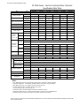
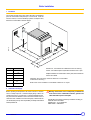
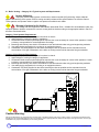
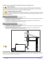
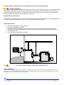
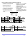
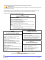
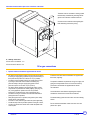
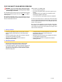
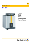
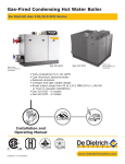
GT 330 A
English
Oil-Gas Fired Hot Water boiler
11/20/09
Installation and operating instructions
Warning:
Before putting the boiler into operation read this manual
carefully.
Warning:
The operating manual is part of the documentation that is
delivered to the installation’s operator. Go through the
information in this manual with the owner/operator and
make sure that he or she is familiar with all the necessary
operating instructions.
85534150
Notice:
This manual must be retained for future reference. Improper
installation, adjustment, alteration, service or maintenance can
cause injury, loss o f life or property damage. Refer to this
manual. For assistance or additional information consult a
qualified installer, service agency or the gas supplier.
11-20-09
Guideline of Notices
Warning:
indicates presence of hazards that can cause, if not
avoided, severe personal injury, death or substantial
property damage.
!
Caution:
indicates presence of hazards t hat will or ca n cause, if not
avoided, minor personal injury or property damage.
Notice:
Application comment for optimum use of equipment and
adjustment as well as useful information.
Safety Considerations
Please observe the following safety instructions.
Read this manual carefully.
Correct in stallation and adjustment of the burner and the control
panel is a precondition for safe, efficient operation of the gas boiler.
Read this manual and the specifications on the safety label carefully
before attempting to put the burner into operation.
not store or use gasoline or other flammable liquids in
Do
the vicinity of this or any other appliance.
Installation and service must be peformed by a qualified
installer, service agency or the gas supplier.
ZReference to an other instruction book.
WHAT TO DO IF YOU SMELL GAS:
- Do not try to light any appliance.
- Do not touch any electric switch, do not use any phone in
your building.
- Immediately call your gas supplier from a neighbor’s
phone. Follow the gas supplier’s instructions.
- If you cannot reach your gas supplier, call the Fire
Department.
Observe the following symbols
DANGER
due to explosion of gas.
- Work only on gas components when you have a license to do so.
- Note t hat the a ssembly of gas and vent connections, the initial
start-up, the electrical connections, the mainte nance and service
can only be perfor med by a licensed se rvice contra ctor or
technician.
!
!
DANGER
due to electricity.
Warning:
Improper installation, adjustment, and/or operation could
- Prior to doing any work on the heating system, disconnect all
electrical power to the boiler at the emergency switch.
- It is NOT sufficient to shut off only the boiler control!
CAUTION!
SYSTEM DAMAGE
due to improper installation.
- Observe l ocal and state codes as well as common i ndustry
practices during the install ation and operation of the heating
appliance.
CAUTION!
SYSTEM DAMAGE
due to inadequate cleaning and maintenance.
- A boiler cleaning and maintenance should be performed annually.
Verify complete system operation at the same time.
- Correct the prob lem immediately to prevent damage to the
system!
!
!
cause carbon monoxide poisoning resulting in injury or
death.
This product must be installed and serviced by a
professional service technician who is experienced and
qualified in hot water boiler installation and gas
combustion.
Caution: Strict compliance with these instructions is a
precondition for the correct operation of the boiler.
IMPORTANT
Service on this boiler should be undertaken only by trained and
skilled personnel.
Keep bo iler area cle ar and free from combustible materials,
gasoline and other flammable vapors and liquids.
Do not place any obstruction in the boiler room that will hinder
the flow of combustion and ventilating air.
Read these instructions carefully before proceeding with the
installation of boiler. Post instructions near boiler for reference
by owner and serviceman.
Maintain instructions in legible condition.
"All installations of this appliance must be be in accordance to all national and local codes and
authorities having jurisdiction"
[Canadian Installation] CSA B139 for Oil & CSA B149 for Gas
[USA Installations] NFPA 54/ANSI Z223.1 for Gas & NFPA 31 for Oil
This boiler must be connected to a venting that will safely and effectively discharge all flue
gases to the outside in an effective manner.
Never burner garbage or paper in the unit, and never leave combustible materials around it.
Do not use gasoline, crankcase draining, or any other oil containing gasoline
2
85534150
11-20-09
Contents
Contents . . . . . . . . . . . . . . . . . . . . . . . . . . . . . . . . . . . . . . . . . . . . . . . . . . . . . . . . . . . . . . . . . . . . . . . . . . . . . . . . . . . .3
Regulations and guidelines . . . . . . . . . . . . . . . . . . . . . . . . . . . . . . . . . . . . . . . . . . . . . . . . . . . . . . . . . . . . . . . . . . . .4
Installation codes. . . . . . . . . . . . . . . . . . . . . . . . . . . . . . . . . . . . . . . . . . . . . . . . . . . . . . . . . . . . . . . . . . . . . . . . . . . . .4
General . . . . . . . . . . . . . . . . . . . . . . . . . . . . . . . . . . . . . . . . . . . . . . . . . . . . . . . . . . . . . . . . . . . . . . . . . . . . . . . . . . . . .4
1
2
3
4
Uncrating . . . . . . . . . . . . . . . . . . . . . . . . . . . . . . . . . . . . . . . . . . . . . . . . . . . . . . . . . . . . . . . . . . . . . . . . . . . . . . . . . . . . . . . . . . . . . . . .4
Packing. . . . . . . . . . . . . . . . . . . . . . . . . . . . . . . . . . . . . . . . . . . . . . . . . . . . . . . . . . . . . . . . . . . . . . . . . . . . . . . . . . . . . . . . . . . . . . . . . .4
Technical specifications of boilers . . . . . . . . . . . . . . . . . . . . . . . . . . . . . . . . . . . . . . . . . . . . . . . . . . . . . . . . . . . . . . . . . . . . . . . . . . . . .5
Main Dimensions . . . . . . . . . . . . . . . . . . . . . . . . . . . . . . . . . . . . . . . . . . . . . . . . . . . . . . . . . . . . . . . . . . . . . . . . . . . . . . . . . . . . . . . . . .6
Boiler Installation. . . . . . . . . . . . . . . . . . . . . . . . . . . . . . . . . . . . . . . . . . . . . . . . . . . . . . . . . . . . . . . . . . . . . . . . . . . . .7
1 Installation . . . . . . . . . . . . . . . . . . . . . . . . . . . . . . . . . . . . . . . . . . . . . . . . . . . . . . . . . . . . . . . . . . . . . . . . . . . . . . . . . . . . . . . . . . . . . . .7
2 Ventilation. . . . . . . . . . . . . . . . . . . . . . . . . . . . . . . . . . . . . . . . . . . . . . . . . . . . . . . . . . . . . . . . . . . . . . . . . . . . . . . . . . . . . . . . . . . . . . . .7
3 Assembly . . . . . . . . . . . . . . . . . . . . . . . . . . . . . . . . . . . . . . . . . . . . . . . . . . . . . . . . . . . . . . . . . . . . . . . . . . . . . . . . . . . . . . . . . . . . . . . .7
Piping . . . . . . . . . . . . . . . . . . . . . . . . . . . . . . . . . . . . . . . . . . . . . . . . . . . . . . . . . . . . . . . . . . . . . . . . . . . . . . . . . . . . . .8
1
2
3
4
Dimensional information required. . . . . . . . . . . . . . . . . . . . . . . . . . . . . . . . . . . . . . . . . . . . . . . . . . . . . . . . . . . . . . . . . . . . . . . . . . . . . .8
Recommendations . . . . . . . . . . . . . . . . . . . . . . . . . . . . . . . . . . . . . . . . . . . . . . . . . . . . . . . . . . . . . . . . . . . . . . . . . . . . . . . . . . . . . . . . .8
Filling . . . . . . . . . . . . . . . . . . . . . . . . . . . . . . . . . . . . . . . . . . . . . . . . . . . . . . . . . . . . . . . . . . . . . . . . . . . . . . . . . . . . . . . . . . . . . . . . . . .8
Ancillaries . . . . . . . . . . . . . . . . . . . . . . . . . . . . . . . . . . . . . . . . . . . . . . . . . . . . . . . . . . . . . . . . . . . . . . . . . . . . . . . . . . . . . . . . . . . . . . . .9
Combustion and ventilation . . . . . . . . . . . . . . . . . . . . . . . . . . . . . . . . . . . . . . . . . . . . . . . . . . . . . . . . . . . . . . . . . . .10
1 Clearances . . . . . . . . . . . . . . . . . . . . . . . . . . . . . . . . . . . . . . . . . . . . . . . . . . . . . . . . . . . . . . . . . . . . . . . . . . . . . . . . . . . . . . . . . . . . . .10
2 Replacement procedures . . . . . . . . . . . . . . . . . . . . . . . . . . . . . . . . . . . . . . . . . . . . . . . . . . . . . . . . . . . . . . . . . . . . . . . . . . . . . . . . . . .11
3 Dimensional information required for connection of the boiler . . . . . . . . . . . . . . . . . . . . . . . . . . . . . . . . . . . . . . . . . . . . . . . . . . . . . . .12
Oil or gas connections . . . . . . . . . . . . . . . . . . . . . . . . . . . . . . . . . . . . . . . . . . . . . . . . . . . . . . . . . . . . . . . . . . . . . . .12
1 Specific technical information supplied with the burner . . . . . . . . . . . . . . . . . . . . . . . . . . . . . . . . . . . . . . . . . . . . . . . . . . . . . . . . . . . .12
Electrical . . . . . . . . . . . . . . . . . . . . . . . . . . . . . . . . . . . . . . . . . . . . . . . . . . . . . . . . . . . . . . . . . . . . . . . . . . . . . . . . . . .13
1 Wiring . . . . . . . . . . . . . . . . . . . . . . . . . . . . . . . . . . . . . . . . . . . . . . . . . . . . . . . . . . . . . . . . . . . . . . . . . . . . . . . . . . . . . . . . . . . . . . . . . .13
2 Wiring procedure . . . . . . . . . . . . . . . . . . . . . . . . . . . . . . . . . . . . . . . . . . . . . . . . . . . . . . . . . . . . . . . . . . . . . . . . . . . . . . . . . . . . . . . . .13
3 Wiring boiler panel . . . . . . . . . . . . . . . . . . . . . . . . . . . . . . . . . . . . . . . . . . . . . . . . . . . . . . . . . . . . . . . . . . . . . . . . . . . . . . . . . . . . . . . .14
Start up procedures. . . . . . . . . . . . . . . . . . . . . . . . . . . . . . . . . . . . . . . . . . . . . . . . . . . . . . . . . . . . . . . . . . . . . . . . . .15
1 Start up procedures . . . . . . . . . . . . . . . . . . . . . . . . . . . . . . . . . . . . . . . . . . . . . . . . . . . . . . . . . . . . . . . . . . . . . . . . . . . . . . . . . . . . . . .16
2 Shut-down procedures . . . . . . . . . . . . . . . . . . . . . . . . . . . . . . . . . . . . . . . . . . . . . . . . . . . . . . . . . . . . . . . . . . . . . . . . . . . . . . . . . . . . .16
Maintenance . . . . . . . . . . . . . . . . . . . . . . . . . . . . . . . . . . . . . . . . . . . . . . . . . . . . . . . . . . . . . . . . . . . . . . . . . . . . . . . .17
1 Boiler . . . . . . . . . . . . . . . . . . . . . . . . . . . . . . . . . . . . . . . . . . . . . . . . . . . . . . . . . . . . . . . . . . . . . . . . . . . . . . . . . . . . . . . . . . . . . . . . . .17
Service and maintenance schedule . . . . . . . . . . . . . . . . . . . . . . . . . . . . . . . . . . . . . . . . . . . . . . . . . . . . . . . . . . . . .19
Spare parts - GT 300 A/II . . . . . . . . . . . . . . . . . . . . . . . . . . . . . . . . . . . . . . . . . . . . . . . . . . . . . . . . . . . . . . . . . . . . . .20
85534150
11-20-09
3
Regulations and guidelines
The installation and operating instructions shown here are given as a
guide for installation and operation and are not meant to replace any
State or Local Codes that may appl y to the individual installation.
Good engineering practice should be used. Any deviation from laws
or regulations or industry Code or these instructions will void the
boiler warranty and any other respon sability or liability of t he De
Dietrich Thermiques S.A.
Only a qualified and licenced heating professional is to carry out the
removal, installation, startup and maintenance of this boiler. The boiler must
be installed according to all national and local codes having jurisdiction. The
operation of the boiler must be verified and all safety controls checked. Any
defect or abnormal operations must be corrected immediately. The entire
system requires annual service and cleaning at least once a year.
Installation codes
• THE BOILER SHALL BE A SSEMBLED AND INSTALLE D BY A
QUALIFIED PROFESSIONAL ONLY. STRICT COMPLIANCE WITH
THESE INSTALLATION AND OPER ATING INSTRUCTIO NS IS A
PRECONDITION FOR THE CORRECT AND GUARANTEE OF THE
BOILER.
• TH E INSTALLATION MUST CON FORM TO TH
E
REQUIREMENTS OF THE AUTHORITY HAVING JURISTRICTION
OR, IN THE ABSENCE OF SUCH REQUIREMENTS, TO THE CAN/
CGA B-149 FUEL GAS INSTALLATION CODES AND CSA B-139
OIL INSTALLATION CODES.
• WHERE REQ
UIRED BY THE AUTHORITY HAVING
JURISTRICTION, THE INSTALLATION MUST CONFORM TO THE
STANDARD FOR CONTROLS AND SAFETY DEVICES
FOR
AUTOMATICALLY FIRED BOILERS ANSI/ASME CSD-1.
• THE INSTALLATIO N OF THE RELIEF VALVE SHALL
BE
CONSISTENT WITH ANSI/ASME B OILER PRESSURE VES SEL
CODE, SECTION IV CSA B51.
• THE BOILER MUST NOT BE INSTALLED ON CARPETING.
• IF AN EXTE RNAL ELECTRICAL SOURCE IS UTILIZED, THE
BOILER WHEN INSTALLED, MUST BE ELECTRICALLY BONDED
TO GROUND IN ACCORDANCE WITH THE REQUIREMENTS OF
THE AUTHORITY HAVING JU RISTRICTION OR, IN T HE
ABSENCE O F SUCH REQUIREMENTS , WI TH THE CANADIAN
ELECTRICAL CODE PART 1, CSA C22.1, ELECTRICAL CODE.
ALL WIRES PRIOR TO DISCONNECTION WHEN
LABEL
SERVICING CONTROLS. WIRING CAN CAUSE IMPROPER
OPERATION AFTER SERVICINGS. “VERIFY PROPER
OPERATION AFTER SERVICE”.
General
The GT330 A are series of oil or gas fired, cast iron, automatic
boilers.
1 Uncrating
Upon arrival, check shipment to ensure all parts have been shipped.
Inspect all items for delivery damage. Report all damage and
shortages to the delivery carrier. Report any damage and shortages
to the Distributor.
2 Packing
See the separate assembly instruction book.
For the optional equipment you may use with this boiler, see the
current price list.
4
85534150
11-20-09
GT 300 A/II Technical Specification Table
GT 330A Series - Cast Iron Sectional Boiler Technical
Specification Data Table
Model
Item
Unit
GT 334A
GT 335A
Firing Sequence
[CSA] - Gas Input
[CSA] - # 2 Fuel Oil Input
[CSA] - Output [Gas-Oil]
GT 336A
GT 337A
GT 338A
GT 339A
Consult Burner Technical Data
MBH
404
598
808
1,024
1,226
1,442
kW
118
175
237
300
359
423
US GPH
2.80
4.15
5.60
7.10
8.50
10.00
MBH
344
510
688
872
1,044
1,229
kW
100.8
149.4
201.6
255.7
306.1
360.1
NET I=B=R Water Rating
MBH
299
443
598
759
908
1,068
Cast Iron Sections
#
4
5
6
7
8
9
Flue-way baffles
#
6
10
10
10
12
12
US Gal
25.36
30.65
35.93
41.22
46.50
51.78
Liter
96
116
136
156
176
196
18° F
Ft. H2O [mbar]
0.483 [14.451]
1.026 [30.674]
2.099 [62.730]
3.055 [91.326]
4.380 [130.923]
6.332 [189.269]
27° F
Ft. H2O [mbar]
0.215 [6.421]
0.457 [13.673]
0.933 [27.884]
1.358 [40.585]
1.945 [58.144]
2.818 [84.240]
36° F
Ft. H2O [mbar]
0.121 [3.615]
0.256 [7.666]
0.525 [15.682]
0.764 [22.831]
1.094 [32.709]
1.583 [47.317]
Water Capacity
Water
Resistance
[∆T = °F]
Diameter
[equivalent]
Combustion
Chamber
Dimensions
Depth
Volume
Combustion chamber
and flue way volume
Volume
ASME MAWP [Water]
Inch
14.84
mm
377
Inch
22.48
28.78
35.08
41.38
47.68
53.98
mm
571
731
891
1,051
1,211
1,371
3
3.39
4.31
5.23
6.14
7.06
7.98
m3
0.096
0.122
0.148
0.174
0.2
0.226
Ft3
5.76
7.27
8.79
10.31
11.83
13.35
0.163
0.206
0.249
0.292
0.335
0.378
957
1,146
1,348
Ft
m
3
90
PSI
MBH
Electrical Connection
V/P/H
120/1/60 < 10A
Max. Water Temp.
Safety Limit [MR]
°F
Fixed non adjustable 248
S3NA Panel
Min. Safety Relief Capacity
Water Operating
Temperature Range
Chamber Resistance
378
560
755
°C
Fixed non adjustable 120
°F
Adjustable 104 - 212 [factory preset stop at 185] Optional Hi-Temperature kit available
°C
Adjustable 40 - 100 [factory preset stop at 85] Optional Hi-Temperature kit available
Inch w.c.
0.14
0.34
0.67
0.95
1.29
1.45
mbar
0.30
0.60
1.10
1.60
2.20
2.50
Gas-Vent Category
#
Boiler Vent Connection
Inch
7
7
7
8
8
8
lb
1,349
1,623
1,865
2,163
2,432
2,712
kg
612
736
846
981
1103
1230
Weight [Dry]
I-II-III-IV & Sidewall
Note:
•
•
•
•
•
•
•
•
•
CSA - MBH Output based on Thermal Efficiency Test According to ANSI Z21.13a/CSA 4.9a-2005
All Models Certified for 0 - 4,500 feet ASL installation altitude, consult factory for higher altitudes
[NET] MBH Output Factor 1.15, Allowance for Piping and Pickup Losses
Chamber Resistance Based on Neutral Chimney-Vent Pressure
Conversion Btu/Hr to kW = 3,412 Btu/Hr per kW
All Models are Design Certified & Eligible to Bear Approval Marking as Shown.
All Models Certified to Fire; # 2 oil, Natural & Propane Gases. Consult factory for Available Burners.
All Models Comply and Certified in Accordance to the latest Canadian & US standards
Due to ongoing and continuous product improvements, DDR Americas Inc. reserves all rights to amend and delete information provided on this
product specification table.
4 Main Dimensions
GT 330 A
A
A
C
B
D
A Water flow tapping 2 1/2" NPSC
C Drain 1 1/2" FPT
B Water return 2 1/2" NPSC
D Rp 2 1/2 diameter sludge removal hole
Type of boiler
GT 334 A
GT 335 A
GT 336 A
GT 337 A
GT 338 A
GT 339 A
L
385/8"
4459/64"
517/32
5733/64"
6313/16"
707/64"
P
199/32
2519/32"
317/8
383/16"
4431/64"
5025/32"
ØR
7"
7"
7"
8"
8"
8"
G50_0001
X
Dimension "X" Max. Burner Length (inches)
Boiler Model
GT334 A
GT335 A
Riello
GT338 A
Power Flame
19
221/4
26
15/32
GT339 A
23
251/8
Notes:
- Dimension are for gas burner only
- Oil and combination oil/gas, refer to b
specifications
6
Fuel Master
Gordon Piatt
191/4
26
10
GT336 A
GT337 A
Weishaupt
urner manufacturer
Boiler Installation
1 Installation
The GT 300 A/II boiler has a bas e frame, although a housekeeping
pad is re commended to keep steel par ts out of casual water. Its
furnace is closed, so it is not necessary to place it on a fireproof floor,
but the floor must be able to bear the weight.
4"1
/8
8553N138
46"
59/
64
40"
20"
L
31"
32
11/
20"
X
Boiler type
L
GT 304 A/II
33"
GT 305 A/II
395/16"
GT 306 A/II
459/16"
GT 307 A/II
517/8"
GT 308 A/II
583/16"
GT 309 A/II
641/2"
Dimension 'X', consult burner info. additional 24 inches for servicing
Caution : note addtional space required when the burner door is open.
Multiple installation of several boilers side by side, these dimensions
need to be modified.
Illustration above showing minimum distances to combustible
materials and servicing.
Boiler must not be installed on combustible material or on carpet.
2 Combustion Air Supply
Boilers operating in atmospheres t hat contain fluorides or chlorides
such as beauty shops and automotive repair garage s whe re air
conditioning services are performed or industrial applications that
may have corrosive elements in the air must have a clean source of
combustion and ventilation air. Bo iler damage by contaminants will
void the warranty and any other responsibility or liability of De Dietrich
Thermique/FES Ltd.
85534150
Ensure boiler room is adequately ventilated and
Warning:
clear and free from combustible materials, gasoline and
other flammable vapours and liquids.
Combustion air supply must be provided according to
national and local codes:
CSA B149.1 -.2 & CSA B139
ANSI Z223.1 & NFPA 31
11-20-09
7
Venting
5.
. Boiler Venting & Chimney General
Caution & Warning:
It is advised and recommended that the heating contractor-professional apply vent materials that are approved and agency listed.
Installation of any venting must follow all local codes in conjunction with vent manufacturer instructions and appliance manufacturer
instructions.
All De Dietrich GT series oil-gas fired cast iron boilers are high performance boilers that could operate under all 4 vent
categories as established by ANSI Z21.13/CSA 4.9 Standard. To assist with application where the vent category is
unknown a graph below has been provided to assist you in determining the vent category and what venting materials
would be acceptable. Although the gas vent categories were developed specifically for gas fired appliances, using this
information is helpful for oil fired boilers. It is very important the venting be selected according to the conditions that the
boiler will operate under, minimum and maximum firing conditions of the boiler must be respected. The venting installed
must comply and be certified to all applicable codes and standards for each jurisdiction.
Gas-Vent Category [4] Definitions:
Cat. I
A Boiler, which operates with a non-positive vent (breech) pressure
and flue gas temperatures which avoids excessive condensation
production in the chamber and venting.
Cat. III
A Boiler, which operates with a positive vent (breech) pressure and
flue gas temperatures which avoids excessive condensation
production in the chamber and venting.
Cat. II
A Boiler, which operates with a non-positive vent (breech) pressure
and flue gas temperatures produce condensation production in the
chamber and venting.
Cat. IV
A Boiler, which operates with a positive vent (breech) pressure and
flue gas temperatures produces condensation production in the
chamber and venting.
Chart A
Chart created by Craig Holdforth
Gas-Fired Appliance Vent Categorization
[According to ANSI Z21.13/CSA 4.9 Gas Boiler Standard]
Carbon Dioxide [CO2] Content %
7
8
9
10
11
12
11
10
9
8
500
456
6
260
Category III
Typical Vent Types
[BH, AL294C®, 304-316L SS]
Category I
Typical Vent Types [A,B,C & L]
412
Chimney-Vent Flue Gas Temperature °F
(Net, Minus Room Temperature)
7
236
211
368
187
324
162
280
138
236
113
192
89
148
104
Category II
Typical Vent Types
[BH, AL294C®, 304-316L SS]
Category IV
Typical Vent Types
[BH, AL294C®, 304-316L SS]
60
Chimney-Vent Flue Gas Temperature °C
(Net, Minus Room Temperature)
6
64
40
15
Negative
Chimney-Vent Pressure
[Inches w.c.]
Positive
9
85534150
11-20-09
5.1 Boiler Venting – Category I & II Typical Layouts and Requirements.
Caution & Warning:
Improperly sealed venting system could result in carbon monoxide [CO] poisoning; ensure adequate
support and fastening of the system. Ensure venting can safely exhaust all flue gases outside in an effective manner.
These systems must operate under a negative vent pressure condition that is stable.
Warning & Cautions for Co-Venting:
Co-venting with other appliances shall conform latest ANSI Z223.1 & CAN/CGA 149 installation codes, any
improper operation shall be corrected, the common venting shall be sized according to the appropriate tables in Part II of
the above mentioned codes.
Category I Vent Systems Requirements:
1. Flue gas temperatures above the green line shown in chart A.
2. Approved type of venting for category I appliances.
3. A barometric draft control maybe employed as required, but is not necessary for correct boiler operation. Consult
a chimney-vent specialist for correct application and usage.
4. Breeching and chimney vent sized in accordance to local and national codes or by good engineering methods.
5. Vent safety device equipped on the venting or as equipped on burner.
6. Condensate TEE fitting supplied on the boiler breeching as close as possible and be orientated to avoid
accumulation of flue gas condensation in the boiler or venting is also used to determine flue gas emissions.
Category II Vent Systems Requirements:
1. Flue gas temperatures below the green line shown in chart A.
2. Approved type of venting for category II appliances.
3. A barometric draft control maybe employed as required, but is not necessary for correct boiler operation. Consult
a chimney-vent specialist for correct application and usage.
4. Breeching and chimney vent sized in accordance to local and national codes or by good engineering methods.
5. Vent safety device equipped on the venting or as equipped on burner.
6. Condensate TEE fitting supplied on the boiler breeching as close as possible and be orientated to avoid
accumulation of flue gas condensation in the boiler or venting is also used to determine flue gas emissions.
Lined Masonry Chimney
Caution-Warning:
Flue gas condensation is very aggressive and corrosive which could lead to failure of the venting system or drains, consult local and national codes
regarding flue gas condensation disposal. The P-trap assembly must be properly filled with water to avoid escape of flue gas emissions. The flue gas
condensation may require neutralization prior to entering the drain.
10
85534150
11-20-09
5.2 Boiler Venting – Category III & IV Vent Systems Typical Layouts and Requirements.
Caution & Warning:
Improperly sealed venting system could result in carbon monoxide [CO] poisoning; ensure adequate
support and fastening of the system. Ensure venting can safely exhaust all flue gases outside in an effective manner.
These systems must operate under a positive vent pressure condition that is stable.
Warning & Cautions for Co-Venting:
Co-venting with other appliances shall conform latest ANSI Z223.1 & CAN/CGA 149 installation codes, any
improper operation shall be corrected, the common venting shall be sized according to the appropriate tables in Part II of
the above mentioned codes.
Category III Vent Systems Requirements:
1. Flue gas temperatures above the green line shown in chart A.
2. Approved type of venting for category III appliances
3. Breeching and chimney diameter sized in accordance to national & local codes or by good engineering methods.
4. Vent safety device equipped on burner [MR]
5. Condensate TEE fitting supplied on the boiler breeching as close as possible and be orientated to avoid
accumulation of flue gas condensation in the boiler or venting.
Category IV Vent Systems Requirements:
1. Flue gas temperatures below the green line shown in chart A.
2. Approved type of venting for category IV appliances
3. Breeching and chimney diameter sized in accordance to national & local codes or by good engineering methods.
4. Vent safety device equipped on burner [MR]
5. Condensate TEE fitting supplied on the boiler breeching as close as possible and be orientated to avoid
accumulation of flue gas condensation in the boiler or venting.
Caution-Warning:
Flue gas condensation is very aggressive and corrosive which could lead to failure of the venting system or drains, consult local and national codes
regarding flue gas condensation disposal. The P-trap assembly must be properly filled with water to avoid escape of flue gas emissions. The flue gas
condensation may require neutralization prior to entering the drain.
11
85534150
11-20-09
5.3 Boiler Venting – Side-Wall or Direct Vent Systems Typical Layouts and Requirements.
Caution & Warning:
Improperly sealed venting system could result in carbon monoxide [CO] poisoning; ensure adequate support
and fastening of the system. Ensure venting can safely exhaust all flue gases outside in an effective manner. These
systems must operate under a positive vent pressure condition that is stable. Do not Co-Vent with any other appliance,
the venting system was designed for single appliance venting only.
Side-wall & Direct Vent Systems:
These systems do not fall under any of the gas vent categories, these systems are pre-engineered. These applications of
this venting system must be followed exactly, for safe, efficient and trouble free operation.
System Requirements:
1. Venting sized accordance to direct vent table
2. Type “BH” [AL294C®] vent material
3. Condensate TEE fitting supplied on the boiler breeching as close as possible and be orientated to avoid
accumulation of flue gas condensation in the boiler or venting is also used for determining flue gas emissions.
4. Vent termination TEE
5. Vent safety device equipped on burner [MR]
Vent Termination Locations & Warning – See Section 5.5
Caution-Warning:
Flue gas condensation is very aggressive and corrosive which could lead to failure of the venting system or drains, consult local and national codes
regarding flue gas condensation disposal. The P-trap assembly must be properly filled with water to avoid escape of flue gas emissions. The flue gas
condensation may require neutralization prior to entering the drain.
12
85534150
11-20-09
5.4 Boiler Venting – Side-wall or Direct Vent Systems Sizing Tables & Vent Safety Device
•
Vent termination must be a TEE type, follow warning
regarding termination locations. Do not include the
termination TEE length in the vent length calculation.
•
Venting shall be sloped, so any condensation developed will
drain through the condensate TEE fitting
Minimum vent length [equivalent] 5 ft. [1.5m]
•
Maximum number of 90° elbows = 2 or 3 45° elbows, each
90° elbow is equivalent to 10 ft. or straight pipe, the 45°
elbow is equivalent = 5 ft.
Vent safety device, differential air pressure switch [manual
reset] NC switch opens on rise of pressure.
•
Optional function of power burners which can employ an
post purge function to exhaust flue gases for a fixed time [1
minute to 4 minutes maximum]
•
Burner employing a standby air damper closed position, the
closed position should be slightly opened to allow hot flue
gases to escape upward through venting and not be
entrapped in the combustion head. Important note, that in
negative building pressures, the observation and odor of flue
gases may enter the boiler room.
•
All venting lengths must be calculated to equivalent lengths,
all application must include at least one 90° elbow
•
Venting must be a type ‘BH” [AL294C® material]
•
Maximum vent length [equivalent] = 30 ft. [9m]
•
•
•
Condensate TEE must be provided [equivalent length = 7 ft.]
•
Appliance reducing adapter [equivalent length 3 ft.]
•
Sealed combustion, combustion air intake sizing, must be
sized according to the burner manufacturers instructions
•
Vent [breeching] pressure shall not exceed 0.20 inches w.c.
[0.50 mbar]
Determining vent length [equivalent] Example:
Appliance reducing adapter
Condensate TEE
12” vent straight vent pipe
Elbow 90°
Termination TEE
[x1] = 3 ft.
[x1] = 7 ft.
[x3] = 3 ft.
[x1] = 10 ft.
[x1] = 0 ft.
Length [equivalent] =
23 ft.
GT 330 A Series
Model
Boiler
Connection ø
GT 430 A Series
Oil-Gas
Vent ø
[∆p] Pressure switch
Setting [inches w.c.]
GT 334 A
7 inch
5 inch
GT 335 A
7 inch
5 inch
GT 336 A
7 inch
5 inch
GT 337 A
8 inch
6 inch
GT 338 A
8 inch
6 inch
GT 339 A
8 inch
6 inch
Model
Boiler
Connection ø
Set vent safety
pressure switch
150% above burner
gas manifold or
head pressure
setting
Oil-Gas
Vent ø
GT 530-15A
16 inc
12 inch
GT 530-16A
16 inc
12 inch
GT 530-17A
16 inc
12 inch
GT 530-18A
16 in
12 inch
GT 530-19A
16 inc
12 inch
GT 530-20A
16 inc
12 inch
Model
[∆p] Pressure
switch Setting
[inches w.c.]
Oil-Gas
Vent ø
GT 430-8A
10 inch
GT 430-9A
10 inch
8 inch
GT 430-10A
10 inch
8 inch
GT 430-11A
12 inch
10 inch
GT 430-12A
12 inch
10 inch
GT 430-13A
12 inch
10 inch
GT 440-14A
12 inch
GTE 530 A Series
[∆p] Pressure
Model
switch Setting
[inches w.c.]
Set vent safety
pressure switch
150% above
burner gas
manifold or
head pressure
setting
Boiler
Connection
ø
8 inch
Boiler
Connection ø
Set vent safety
pressure switch
150% above
burner gas
manifold or
head pressure
setting
10 inch
Oil-Gas
Vent ø
GT 530-21A
16 inch
12 inch
GT 530-22A
18 inch
14 inch
GT 530-23A
18 inch
14 inch
GT 530-24A
18 inch
14 inch
GT 530-25A
18 inch
14 inch
[∆p] Pressure
switch Setting
[inches w.c.]
Set vent safety
pressure switch
150% above
burner gas
manifold or
head pressure
setting
13
85534150
11-20-09
5.5 All Side-wall and direct Vent termination locations installation precautions:
Warning/Caution:
In all cases avoid potential vent termination locations where excess debris or snow could accumulate and bock the
vent termination to any degree.
Minimum clearance of 4 ft. [1.22m] horizontally from, and in no case above or below, unless a 4 foot [1.22m]
horizontal distance is maintained, from electric meters, gas meters, regulators & relief equipment.
Do Not Co-Vent Any Direct Vent or Sidewall Venting System
B149.1
(GAS INSTALLATIONS CANADA)
A VENT SHALL NOT TERMINATE…..
Directly above a paved sidewalk or driveway which serves 2 buildings.
Less than 7 ft. any paved sidewalk or drive way
Less than 6 ft. of a combustion air inlet to any building
Less than 4 ft. above a meter/regulator assembly [horizontally] of the vertical center-line of the
regulator vent outlet to a maximum vertical distance of 15 ft.
Less than 4 ft. of any gas service regulator vent outlet
Less than 1 ft. above grade or normal anticipated snow level for the area
Less than 3 ft. from windows, doors [that can be opened], combustion air supply or any appliance
or building.
Underneath a veranda, porch or deck unless:
1. The veranda, porch or deck is fully open on a minimum of 2 sides beneath the floor
&
2. The distance between the top of the vent
termination and the underside of the veranda, porch or deck is greater than 1 ft.
B139-00
(OIL INSTALLATIONS CANADA)
A VENT SHALL NOT TERMINATE…..
Directly above a paved sidewalk or driveway which serves 2
buildings.
Less than 7 ft. any paved sidewalk or drive way
Less than 6 ft. from an open-able window, door or mechanical
combustion air supply
Less than 6 ft. of any combustion air inlet
Less than 3 ft. of the vertical centerline of the meter/regulator
assembly on a horizontal plane perpendicular to the regulator
Less than 6 ft. of gas service regulator vent outlet
Less than 4 ft. of oil tank vent or oil tank fill inlet
Less than 1 ft. above grade or normal anticipated snow level for the
area.
Within 6 ft. of a property line
Underneath a veranda, porch or deck
Flue gases are within 6 ft. of combustible material or any openings of
surrounding buildings.
Less than 3 ft. from an inside corner or L-shaped structure
Where flue gases may be directed towards brickwork, siding or other
construction that may cause damaged from heat or condensate from
the flue gases.
NFPA 54 / ANSI Z223
(GAS INSTALLATIONS USA)
A VENT SHALL NOT TERMINATE…..
ٛ
ٛ
ٛ
ٛ
Less than 3 ft. of any combustion air inlet source located within 10 ft.
Less than 1 ft. from any obstructions
Less than 1 ft. above grade or normal anticipated snow level for the area.
Over public walkways, driveways or other areas where condensate or
vapor could create nuisance or hazard or could be detrimental to the
operation of regulators, relief's, valves or other equipment
NFPA 31
(OIL INSTALLATIONS USA)
A VENT SHALL NOT TERMINATE…..
ٛ
ٛ
ٛ
ٛ
ٛ
ٛ
ٛ
Less than 5 ft. from vent outlet of the supply tank
Less than 7 ft. above walkways
Less than 1 ft. from any door, window or air inlet source
Less than 1 ft. from grade or snow level.
Less than 3 ft. from a air intake that is within 10 ft
Less than 1 ft. from soffit of the roof
Less than 3 ft. from any building corner or L shape structure
WARNING-CAUTION
Consult Local Codes & Authorities for other Requirements not mentioned
14
85534150
11-20-09
6 Dimensional information required for connection of the boiler
15
5 "5
The boiler must be connected to venting system
that will safely and effectively discharge all flue
gases to the outside in an effective manner.
/16
"11
/16
Consult local and national codes regarding the
boiler breeching and chimney sizing.
32"9/16
8553N140A
A
A : chimney connection :
GT 304 A/II to GT 306 A/II : 7" ø
GT 307 A/II to GT 309 A/II : 8" ø
Oil or gas connections
1 Specific technical information supplied with the burner
•
•
•
•
•
•
•
•
The boiler and its individual shutoff valve must be disconnected
from the gas supply piping system during any pressure testing of
that system at test pressures in excess of 1/2 psi (3.5kPa),
The boiler must be isolated from the gas supply piping system
by closing its individual manual shutoff valve during any
pressure testing of the gas supply piping system at test
pressures equal to or less than 1/2 psi (3.5 kPa),
The boiler shall be installed such that the gas ignition system
components are protected from water (dripping, spraying, rain,
etc.) during appliance operation and service (circulator
replacement, condensate trap, control replacement, etc.),
The boiler and its gas connection must be leak tested before
placing the boiler in operation,
After placing the boiler in operation, the ignition system safety
shutoff device must be tested,
Provision for vent, bleed and gas relief lines (when applicable),
A sediment trap must be provided upstream of the gas controls,
Location of manual main shutoff valve outside the jacket when
codes require.
Follow the information and documentation as supplied with
the burner, regarding:
The specific installation requirements, wiring, fuel supply and
piping and all adjustments of the air and fuel and start-up
procedure as be followed as supplied with the burner
documentation
Consult the burner manufacturer regarding the required
maintenance of the burner and the service intervals.
The entire heating system must be check once each heating
season.
Do not start the burner/boiler unless all access cover and
panels are in place.
15
85534150
11-20-09
Electrical
1 Wiring
Wiring in accordance with the requ irements of the authority having
jurisdiction or, in the absence of such requ irements, with the
Canadian Electrical Code Part 1, CSA C22.1, Electrical Codes.
2 Wiring procedure
De Dietrich boiler suggested field wiring procedure.
A
1
1 : Top view
B
2 : Boiler panel
3 : Front
A : Race ways located under top panel of boiler
B : Wiring to be run in electrical race way to boiler control panel from
ancillaries
E
Main power to 4x4 junction box or enter rear of boiler through race
way.
C : 4x4 junction box location
C
2
D : Run BX cable between insulation and casing from boiler panel
D
E : Allow extra cable to swing burner open
3
18
85534150
11-20-09
FOR YOUR SAFETY READ BEFORE OPERATING
If you do not follow these instructions exactly,
WARNING:
a fire or explosion may result causing properly damage,
personal injury or loss of life.
A. This appliance does not have a pilot. It is equipped with an ignition
device wich automatically lights the burner. Do no t try to light the
burner by hand.
B. BEFORE OP ERATING smell all around the appliance area for
gas. Be sure to smell next to the floor because some gas is heavier
than air and will settle on the floor.
WHAT TO DO IF YOU SMELL GAS
•
•
•
•
Do not try to light any appliance.
Do not touch any electric switch; do not use any phone in your
building.
Immediately call your gas supplier from a neighbor’s phone.
Follow the gas supplier’s instructions.
If you cannot reach your gas supplier, call the fire department.
C. Use only your hand to push in or turn the gas control knob. Never
use tools. If the knob will not push inor turn by hand, don’t tryto repair
it: call a qualified service technician. Force or attempted repair may
result in a fire or explosion.
D. Do not use this a ppliance if a ny pa rt h as be en under wa ter.
Immediately ca ll a qualified te chnician to in spect th e appliance
and to replace any part of the control system and any gas control
which has been under water.
1 Start up procedures
•
•
•
•
Inspect for proper baffling insertion into flue passes. All cleanout doors properly sealed. Burner door closed and properly
latched.
Gas and oil systems ready. Proper vent connections. Required
combustion and ventilation air provided.
Waterside of system properly filled and vented of air.
Lighting instruction followed.
•
•
•
To be performed by a licensed tradesperson in accordance with
the guidelines shown in this manual. Follow burner
manufactures instructions.
Mandatory factory start-up report to be completed and returned
to comply with the warranty process.
Proper operating instructions of equipment to be related to
operating personnel.
2 Shut-down procedures
•
•
-
Disengage all electrical power switches to heating system
burners, pumps. Isolate all boiler valves and fuel valves.
For off-season shutdown, open boiler combustion flue ways and
clean. Ensure venting, chimney, combustion and ventilation air
openings free from blockage. Do not drain waterside of system.
Shutoff fuel supply lines
85534150
11-20-09
Maintenance
1 Boiler
It is no t ad visable to drain an in stallation, ex cept in ca se of
absolute necessity. Check the water level of the installation and
top it off if necessary, avoiding a sudden inlet of cold water in the
hot boiler.
Check for system leaks.
Professional water treatment is recommended.
The good performance of the boiler depends on cleanliness.
Cleaning the boiler must be carried out as often as required and at
least, as for the flue once a year.The following operations are always
carried out with the boiler and the power supply shut off.
• Cleaning of the flue gas circuit :
- switch off the electricity supply to the boiler
- unhook the front cover
Ensure all access cover and doors are in place prior to
starting the boiler-burner.
20
85534150
11-20-09
- open the sweeping door (upper door) by unscrewing the 4 lock nuts.
- also brush the convection baffles and the front face,
- remove the convection baffles,
- if possible use a vacuum cleaner,
- using the brush supplied, carefully sweep the 6 flue sections,
- put the convection accelerators back in place (pay attention to their
direction),
- shut the door.
• Maintenance of the combustion chamber
- open the combustion chamber door (lower door) by unscrewing the
4 lock nuts
- brush the inside of the combustion chamber
- using a vacuum cleaner, vacuum up the soot deposits which have
accumulated in the combustion chamber
- close the door and replace the front cover
2
3
4
1
1 : stop pins
3 : vacuum cleaner brush
2 : brush
4 : vacuum cleaner
Baffle Position
Baffle
Fraction
mm
Upper [3rd Pass]
8219-0017
16 1/4
410
Middle [2nd Pass]
8219-0018
22 7/16
570
Lower
[1st Pass]
8219-0019
16 1/4
412
8219-0020
22 1/2
572
GT 334 A
0
4
2
0
GT 335 A
8
0
2
0
GT 336 A
8
0
2
0
GT 337 A
4
4
2
0
GT 338 A
0
8
4
0
GT 339 A
0
8
2
2
• Cleaning the smoke box (Flue Hood)
For this purpose :
-remove the sweeping left and right hand covers of the smoke box (2
wing nuts) and remo ve the soot which has accumulated using a
vacuum cleaner
-replace the sweeping covers.
8553N136
• Burner maintenance :
In accordance with the directions supplied with the burner.
21
85534150
11-20-09
Service and maintenance schedule
`Require annul system inspecti on of the heating boiler, burner
and controls by qualified service personnel,
`Heating sys tem c heck for safe ty control functions, system
pressure, leaks, combustion and ventilation air should be done
on a monthly schedule.
Extended Shutdown Periods
If the system is to be shutdown for any extended period of time, please follow these steps:
1. Shut off all pumps
2. Cap off venting of boiler at the boiler collars
3. Shut off supply & Return Valves
4. Shut off the fuel supply valves
5. Disconnect power at the panel
6. Clean boiler and venting
22
85534150
11-20-09
The Manufacturer:
Bp 30 – 57, RUE DE LA Gare
F – 67580 MERTZWILLER
Tel: +33/3/88/80/27/00 – Fax: +33/3 88 80 27 99
Ni IRC : 347 555 559 RCS STRASBOURG
www.dedietrich-thermique.com
DDR AMERICAS INC.
In Canada:
1090 Fountain St., Unit #10
Cambridge, Ontario, N3E 1A3 - CANADA
Tel: 519.650.0420 Fax: 519.650.1709
In USA or South America:
1054 North DuPage Avenue
Lombard, Illinois, USA 60148
Tel: 630.953.2374 Fax: 630.953.2376
Toll Free 1.800.943.6275
www.dedietrichboilers.com
In the interest of customers, DE DIETRICH & DDR Americas are continuously endeavouring to make improvements in product quality.
All the specifications stated in this document are therefore subject to change without notice